www.PyleUSA.com
2
WARNING:
• For your own safety, please read and understand these
warnings and keep this user guide for future reference.
• Always make sure the cart is fully extended and locked
before use. Always make sure the cart is folded and locked
properly before lifting or transporting.
• Do not run while using this product.
• Do not use accessories other than those designed for use
with your cart.
• Keep all packing materials away from children and recycle
where possible or where required by law.
MAINTENANCE
• To clean the trolley, wipe with a soft, dry cloth.
• Car polish may be used to maintain nish.
• Lubricate moving parts every 6 months.
WARNING:
• Keep hands and ngers away from moving or sliding parts!
• Always keep control of the Golf Push Cart -
Do not let it run down hills without full control.

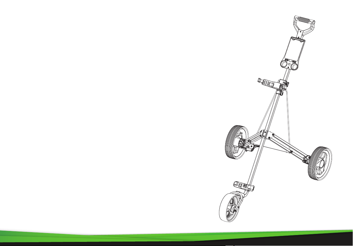
PARTS LIST
A Handle
B Handle Tube
C Scorecard
D Slide Lock
E Upper Bracket
F Joint
G Right Weight Stabilize Rod
G1 Left Weight Stabilize Rod
H 2 Holes Leg Frame
H1 3 Holes Leg Frame
I Rear Wheel Set
J Leg Bracket
K Right Wheel Lock Mechanism
K1 Left Wheel Lock Mechanism
L Anti-Splay Wire
M Mainly Frame
N Lower Bracket
P Front Wheel Set
www.PyleUSA.com
3
A
C
B
E
D
F
G1
G
J
K1
H
L
M
P
N
K
H1
I
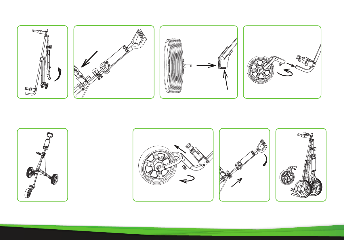
ASSEMBLY STEPS
Fig. 2
Fig. 3
Fig. 4
Lift the handle to
level position as
Fig. 1
Move the slide lock downside
and lock to upper bracket as
Fig. 2
Completely unfolding
and assembly as Fig. 5.
www.PyleUSA.com
4
Fig. 1
Press the button on the
wheel holder to assemble the
rear wheel as Fig.3.
Fig. 7
Through rotating the button to
release the front wheel as Fig.6.
Move the slide lock
toward up to release
the handle as Fig.7.
FOLDING STEPS
Fig. 5
Snap front wheel insert mainly
frame and then rotating the
button tighten it as Fig.4.
Fig. 8
Fig. 8 shows the
folded position.
Fig. 6

ASSEMBLY DETAILS
www.PyleUSA.com
5
1
2
3
Fig. 9 Fig. 10
Fig. 11
Through adjusting the slide hole to adjust the handle height as Fig.9. and
have 3 adjustable position as Fig.10. And for the upper bracket, it suits for the
stand and normal bag as Fig.9.
Push on the brake pedal to stop the
rear wheel and pull o to release as
Fig.11.

Fig. 2Fig. 1 Fig. 3
www.PyleUSA.com
6
FRONT WHEEL ADJUSTMENT MECHANISM
1. If during use, you nd the cart
veers to the right or left, please see
the instructions below to correct
this problem. (Fig.1)
2. If the cart veers to the left, face the
front wheel of the cart and use the
Allen wrench provided to screw
the right bolt counterclockwise or
the left bolt clockwise until the
front wheel is centered between
the front fork. (Fig.2)
3. If the cart veers to the right, face
the front wheel of the cart and use
the Allen wrench provided to screw
the left bolt counterclockwise or
the right bolt clockwise until the
front wheel is centered between
the front fork. (Fig.3)
FEATURES:
• New Deluxe Scorecard Holder
• Upper and Lower Bracket with Strap
• Foam Handle Grip
• Ergonomic Padded Adjustable Handle
• Includes Scorecard Holder, and Patented Bag Holder
• Simple Quick Braking System
• Durable and Compact Size for Easy Storage and Transportation
• Easy to Fold and Unfold
• Designed for Multiple Pushing Positions
WHAT'S IN THE BOX:
• (1) 3-Wheel Golf Push Cart
TECHNICAL SPECS:
• Construction Material: Steel Frame
• Max. Load Capacity: 28.7 lbs.
• Front Wheel Size: 8 -inches
• Rear Wheels Size: 9.5'' -inches
• Folded Product Dimension (L x W x H): 19.9’’ x 14’’x 42.5’’-inches
• Unfolded Product Dimension (L x W x H): 51.2’’ x 28’’ x 38.8’’ -inches
www.PyleUSA.com
7
3. If the cart veers to the right, face
the front wheel of the cart and use
the Allen wrench provided to screw
the left bolt counterclockwise or
the right bolt clockwise until the
front wheel is centered between
the front fork. (Fig.3)

Questions? Comments?
We are here to help!
Phone: (1) 718-535-1800
Email: support@pyleusa.com