Loading ...
Loading ...
Loading ...
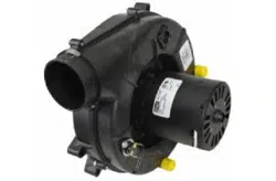
INTEGRATED FAN / IGNITION CONTROL
This furnace is equipped with a combination ignition module and fan control. An electronic device
ignites the burners upon a call for heat. It also controls the venter blower and the various speed
selections of the circulating air blower. This control is located in the circulating air blower
compartment. Upon a demand for heat the venter is energized. After a short purge, the electronic
ignition device is energized. The burners are ignited after a short delay and the burner flame is
proven. The circulating air blower is energized approximately thirty (30) seconds after the burners
are ignited. The circulating air blower off time is field selectable. THIS CONTROL IS NOT FIELD
SERVICEABLE.
I CIRCULATING AIR FILTERS 1
One of the most common causes of problems in a forced air heating system is blocked or dirty
filters. Circulating air filters must be inspected monthly for dirt accumulation and replaced if
necessary. Failure to maintain clean filters can cause premature heat exchanger failure. A new
home may require more frequent replacement until all construction dust and dirt is removed.
Circulating air filters are to be installed external to the furnace cabinet.
Before performing any service on this furnace, including checking or replacing circulating air filters
- disconnect main power.
DO NOT operate the furnace for extended periods of time without filters in place. Dust and dirt in
the air will restrict the air movement over the secondary coil causing nuisance cycling of safety
controls which may result in a "no heat condition."
INPUT BTUH
40,000
60,000
80,000
100,000
120,000
MINIMUM FILTER SIZES
FILTER SIZE
320 / 160 IN. z
480 / 240 IN. z
640 / 320 IN. z
727 / 363 IN. z
960 / 480 IN. z
TYPE
DISPOS./PERMAN.
DISPOS./PERMAN.
DISPOS./PERMAN.
DISPOS./PERMAN.
DISPOS./PERMAN.
I TEMPERATURE RISE 1
The temperature difference between the outlet air and the inlet air of the furnace is known as the
temperature rise. This furnace is designed to operate within the temperature rise displayed on the
furnace series and rating plate. To ensure satisfactory performance, the temperature rise of the
furnace must be measured and adjusted if necessary. Use the following procedure to measure
and adjust the temperature rise;
• Prior to starting the furnace visually inspect all joints and seams in the supply and return air
ducts for leaks. Repair them if necessary.
• Adjust the room thermostat to obtain constant operation.
• Allow the furnace to operate for at least fifteen (15) minutes.
• With an accurate thermometer measure the temperature at the return air grille. If a
combination indoor / outdoor system is used, the temperature must be measured downstream
of the connection.
IO-151 17
Loading ...
Loading ...
Loading ...