Loading ...
Loading ...
Loading ...
Installation instructions en
13
egory III and according to the installation
regulations.
▶ When installing the appliance, check that
the power cable is not trapped or dam-
aged.
13.4 General information
Follow these general instructions during the installation.
¡ For the installation, observe the currently valid build-
ing regulations and the regulations of the local elec-
tricity and gas suppliers.
¡ When discharging the exhaust air, the official and
legal regulations, such as the regional building
code., must be observed.
¡ In order to freely access the appliance for servicing,
select an easy-to-reach installation site.
¡ The surfaces of the appliance are sensitive. Avoid
damaging them during installation.
13.5 Instructions for the electrical
connection
In order to safely connect the appliance to the elec-
trical system, follow these instructions.
WARNING‒Risk of electric shock!
It must always be possible to disconnect the appliance
from the electricity supply. The appliance must only be
connected to a protective contact socket that has been
correctly installed.
▶ The mains plug for the mains power cable must be
easily accessible after the appliance is installed.
▶ If this is not possible, an all-pole isolating switch
must be integrated into the permanent electrical in-
stallation according to the conditions of overvoltage
category III and according to the installation regula-
tions.
▶ The permanent electrical installation must only be
wired by a professional electrician. We recommend
installing a residual-current circuit breaker (RCCB)
in the appliance's power supply circuit.
Sharp-edged components inside the appliance may
damage the connecting cable.
▶ Do not kink or trap the connecting cable.
¡ The connection data can be found on the rating
plate. →Page10
¡ The connecting cable is approx.1.30m long.
¡ This appliance complies with the EC interference
suppression regulations.
¡ The appliance corresponds to protection class 1.
You should therefore only use the appliance with a
protective earth connection.
¡ Do not connect the appliance to the power supply
during installation.
¡ Ensure that the protection against contact is guaran-
teed during installation.
13.6 Information on the installation situation
¡ Install this appliance in a kitchen cupboard.
¡ To install additional special accessory parts, ob-
serve the enclosed installation instructions.
¡ The width of the extractor hood must correspond at
least with the width of the hob.
¡ To optimally detect the cooking vapours, install the
appliance in the middle of the hob.
13.7 Instructions for the exhaust air pipe
The appliance manufacturer does not provide any war-
ranty for faults attributable to the pipeline.
¡ Use a short, straight exhaust air pipe with as large a
pipe diameter as possible.
¡ Long, rough exhaust air pipes, many pipe bends or
small pipe diameters reduce the suction power and
increase the fan noise.
¡ Use an exhaust pipe that is made of non-combust-
ible material.
¡ To prevent condensate from returning, fit the ex-
haust pipe with a 1° gradient from the appliance.
13.8 Installation
Checking the unit
1.
Check whether the fitted unit is level and has suffi-
cient load-bearing capacity.
The maximum weight of the appliance is 18kg.
Note:Note the furniture manufacturer's specifica-
tions with regard to the load-bearing capacity of the
fitted unit.
2.
Ensure that the fitted unit is heat-resistant up to
90°C.
3.
Ensure that the fitted unit is still stable after the cut-
outs have been made.
4.
Ensure that the fitted unit complies with the following
dimensions:
Width 600mm
Depth Min. 320mm
With lowering frame:
Min.350mm
Position Min. 390mm
With CleanAir circulat-
ing-air set, min. 600mm
Wall thickness 16mm or 19mm
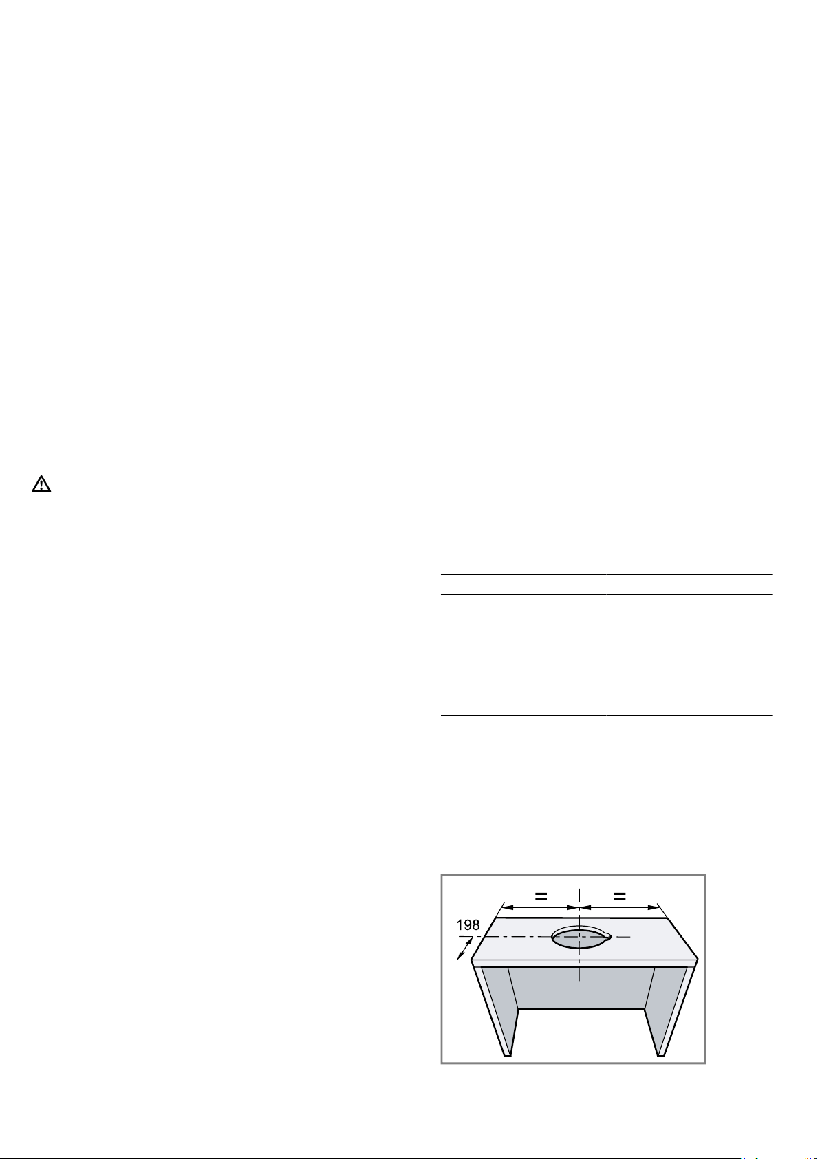
Preparing the units
Requirement:The unit is suitable for the installation.
→"Checking the unit", Page13
1.
Cover the hob to prevent damage.
2.
Ensure that the stability of the fitted unit is guaran-
teed after the cut-outs have been made.
3.
If the cabinet is less than 320mm deep, remove
part of the back panel.
4.
Create the cut-out for the pipe connection.
5.
If the cabinet base is in place, remove it.
Loading ...
Loading ...
Loading ...