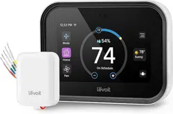
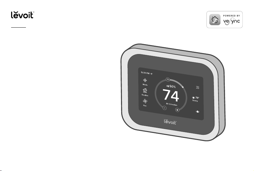
Aura™ Smart Thermostat
USER MANUAL
Questions or Concerns?
Please contact us Mon–Fri, 9:00 am–5:00 pm PST/PDT
at [email protected] or at (888) 726-8520.
Model: LTM-A401S-WUS

2
Table of Contents
Package Contents
Specifications
Safety Information
Installation Guide
Removing Your Old Thermostat
Installing Thermostat with a C Wire
Installing Thermostat without a C Wire
Wiring Diagrams
Getting Started
Overview of Thermostat Modes
VeSync App Setup
VeSync App Functions
Troubleshooting
Warranty Information
Customer Support
2
3
6
8
9
15
22
36
41
43
45
46
47
54
57
Package Contents
1 x Aura Smart Thermostat
1 x Backplate
1 x Power Extender Kit
4 x Screw
4 x Wall Anchor
1 x User Manual
1 x Wire Tag Set
3
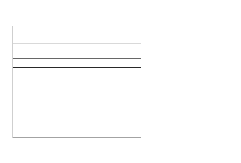
Specications
Power Supply AC 24V, 60Hz
Rated Power 3W
Dimensions 4.68 x 3.49 x 0.98 in / 11.88 x
8.86 x 2.50 cm
Weight 0.37 lb / 0.17 kg
Connectivity 2.4GHz Wi-Fi (802.11 b/g/n),
Zigbee 3.0 (for room sensors)
Temperature Range Setting Range: 32°–99°F /
0°–37°C
Display Range: 32°–104°F /
0°–40°C
Note: The thermostat settings
are limited to 99°F. However,
the thermostat can read up
to 104°F.
4
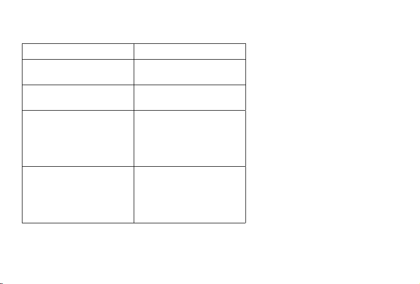
Temperature Increments 1°F / 0.5°C
Relative Humidity (RH)
Display Range
0–99%
Relative Humidity (RH)
Increments
1%
Operating Conditions Temperature: 32°–122°F /
0°–50°C
Relative Humidity:
5–95% (non-condensing)
Storage Conditions Temperature: -4°–140°F /
-20°–60°C
Relative Humidity:
5–95% (non-condensing)
SPECIFICATIONS (CONT.)

5
Compatibility
• 2H/2C Conventional Systems
• 4H/2C Heat Pump Systems or Dual Fuel Systems
• Systems with Rc and Rh Terminals (for separate heating and cooling power supplies)
Important:
This user manual only includes
installation and simple setup
instructions. For the extended
digital manual, which includes full
operating instructions and a user
guide, scan the QR code.
Note: To access additional smart functions, download the free
VeSync app (see page 45).
SPECIFICATIONS (CONT.)
You can also type the following link into a web browser:
www.levoit.com/ltms401swus/downloads

6
SAFETY INFORMATION
READ AND SAVE THESE INSTRUCTIONS
Please read and follow all instructions and safety guidelines in this manual.
• Before installing and wiring, TURN OFF your HVAC system by turning o the appropriate switch or locking the appropriate
circuit breaker in the OFF position.
• Only install the thermostat if you are comfortable with electrical work. If not, contact a qualified electrician. Improper
installation will increase risk of fire, electric shock, and other injuries.
• The thermostat must be installed and used in accordance with the National Electric Code (NEC) or your local electrical code.
• Do not install the thermostat with wet hands.
Installation
Note: Levoit cannot guarantee the quality of installation, and cannot cover associated costs.
• Only install and use the thermostat indoors, in a dry location, and avoiding extreme heat and freezing temperatures.
• Do not modify the thermostat hardware or software.
• Not for commercial use. Household use only.
General Safety
7
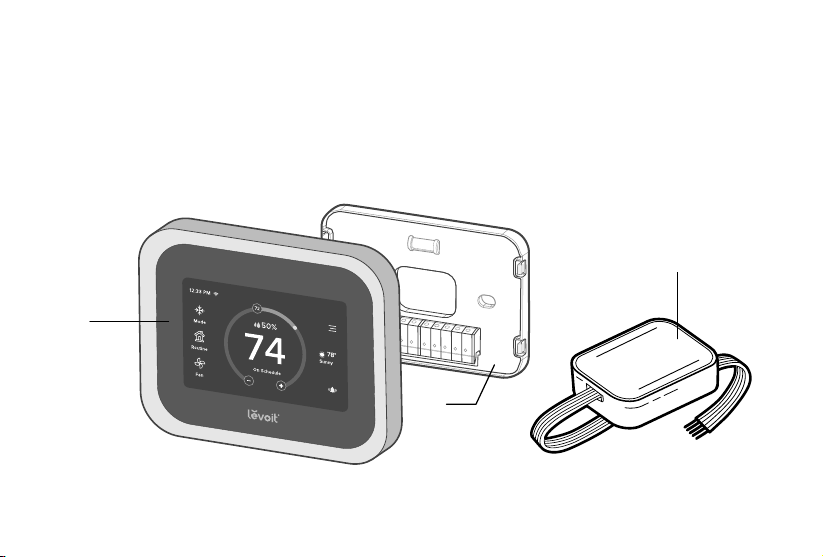
A. Smart Thermostat
B. Backplate
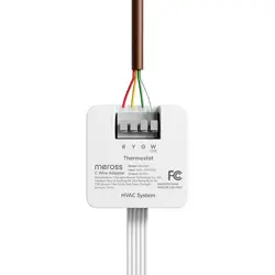
C. Power Extender Kit (PEK)
Function Diagram
A
B
C
8
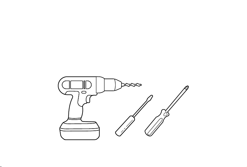
• Electric drill
• 3/16-inch drill bit
• Small flat head screwdriver
• Philips head screwdriver
What You’ll Need
INSTALLATION GUIDE
9
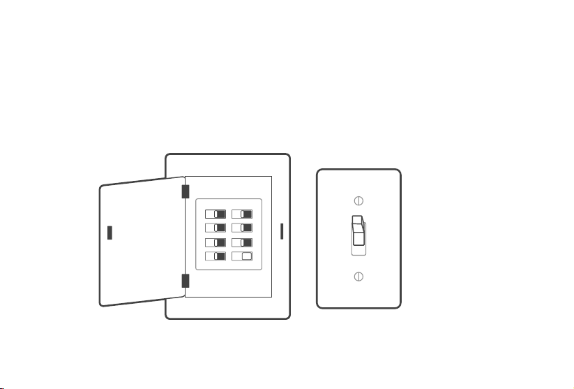
1. Turn o your HVAC system
WARNING: For your safety, you must turn o your HVAC system before removing your old thermostat.
Every HVAC system is dierent, but usually you turn o a master switch or switch the system o in your home’s breaker
box. [Figure 1.1]
Note: The master switch or breaker box is often found in your basement, attic, garage, or utility closet.
Removing Your Old Thermostat
Confirm that the HVAC system is turned o by adjusting the temperature on the thermostat, waiting a few minutes, and
making sure that the HVAC does not turn on.
TURN OFF
Figure 1.1
Breaker Box
Switch
10
REMOVING YOUR OLD THERMOSTAT (CONT.)
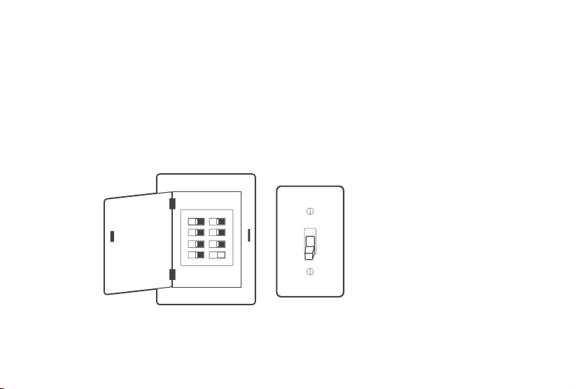
2. Remove your old thermostat
Remove your old thermostat from the wall. Every thermostat is dierent, but usually you will need to push a tab on the
edge of the thermostat and separate the thermostat from the backplate. [Figure 1.2]
Note: Only remove the old thermostat. Do not remove the backplate from the wall yet.
Figure 1.2
11
REMOVING YOUR OLD THERMOSTAT (CONT.)
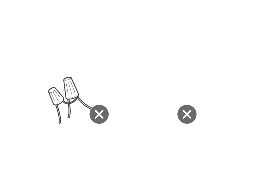
3. Check for compatibility
Inspect the wires leading into the backplate.
If you find thick wires with wire nuts, or if the voltage of your HVAC system is 120V or higher, then your system
is not compatible with this smart thermostat. [Figure 1.3]
Contact Customer Support (see page 57).
Figure 1.3
or
120V
OR
HIGHER
12
REMOVING YOUR OLD THERMOSTAT (CONT.)
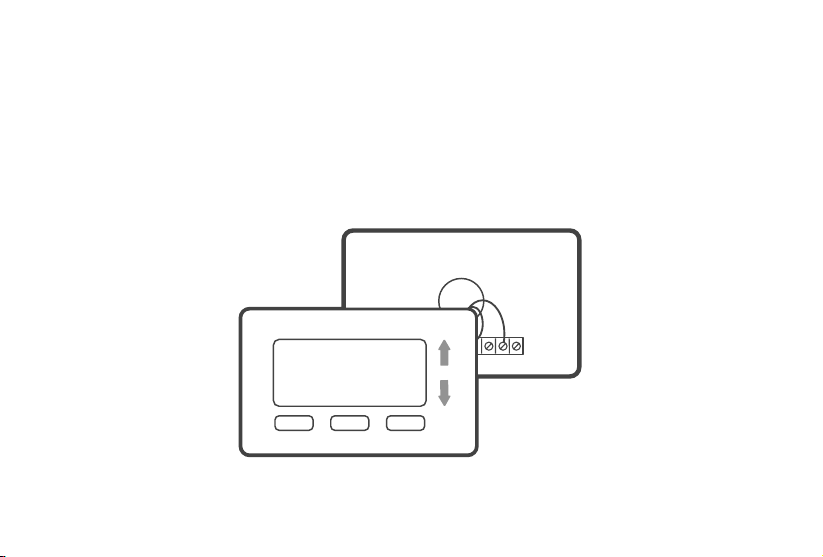
4. Take a photo
Before removing wires, take a picture of how the wires connect to the terminal of your old thermostat. [Figure 1.4]
You may need to reference this photo later.
Figure 1.4
13
REMOVING YOUR OLD THERMOSTAT (CONT.)
5. Find the Thermostat Labels in the included wire tag set. Label the wires according to the corresponding terminals.
[Figure 1.5]
Note: If you are unsure whether your system has a heat pump, we recommend that you research your HVAC
system online or contact Customer Support (see page 57).
Figure 1.6
Figure 1.5
If there are any jumper wires (wires connecting dierent terminals together), do not label these wires. [Figure 1.6]
Remove them and store them with your old thermostat.
The terminals on your old thermostat may already have 2 dierent sets of labeling–one set for a conventional HVAC
system and one set for a heat pump system. If your system has a heat pump, make sure to follow the heat pump labeling.
REMOVE
RC RH Y2 W1 W2 C
O/B
Y1
G
14
REMOVING YOUR OLD THERMOSTAT (CONT.)
6. Carefully disconnect the wires. Each thermostat is dierent, but usually you use a Philips head screwdriver to loosen a
screw or press a release button to remove the wire.
Important:
• Check if you have a C wire connected to your old thermostat. The C wire is used to provide power to the
thermostat. [Figure 1.7]
• If you have a C wire, go to Installing Thermostat with a C Wire (page 15).
• If you do not have a C wire, go to Installing Thermostat without a C Wire (page 22).
Figure 1.7
15
Installing Thermostat with a C Wire:
1. Remove the old backplate
Unscrew the old backplate from the wall. [Figure 2.1] Hold the wires and carefully pull the backplate from the wall, making
sure the wires do not fall into the wall.
Note: If your system has a C wire, you do not need to install the power extender kit (PEK). The thermostat will use the
C wire for power.
Figure 2.1
16
INSTALLING THERMOSTAT WITH A C WIRE (CONT.)
2. Attach the new backplate
Insert the wires through the hole in the new backplate. Use an electric drill to attach the backplate to the wall with the
provided wall anchors and screws. [Figure 2.2]
Figure 2.2
17
INSTALLING THERMOSTAT WITH A C WIRE (CONT.)
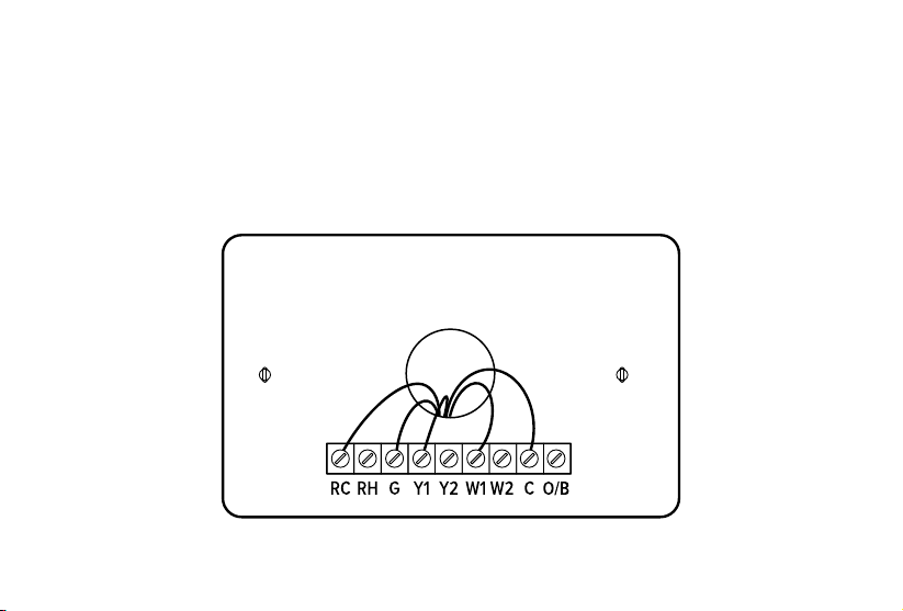
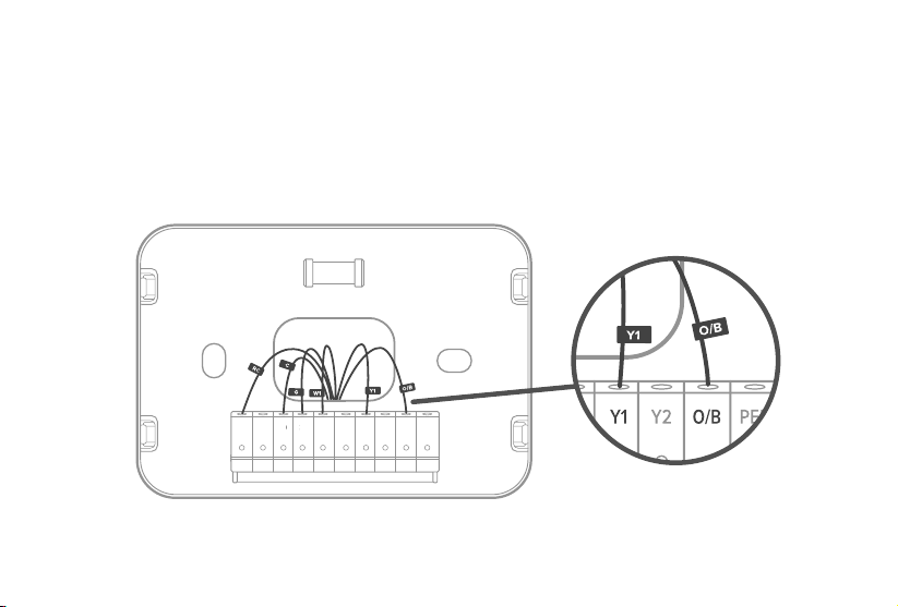
3. Connect the wires
Connect the wires to the corresponding terminals on the backplate (see Wiring Diagrams, page 36). [Figure 2.3]
When you are finished, take a picture.
You may need to refer to the connections in this photo while setting up the thermostat.
Figure 2.3
Rc Rh W1 W2 Y1 Y2 O/B PEK
CG
CG

18
INSTALLING THERMOSTAT WITH A C WIRE (CONT.)
• If you have more than one R wire (R wires include R, Rc, and Rh):
• Connect the R or Rc wire to the Rc terminal, and connect the Rh wire to the Rh terminal.
• If you only have one R wire (R wires include R, Rc, and Rh):
• Connect the R wire—R, Rc, or Rh—to the Rc terminal.
About R Wires:
19
INSTALLING THERMOSTAT WITH A C WIRE (CONT.)
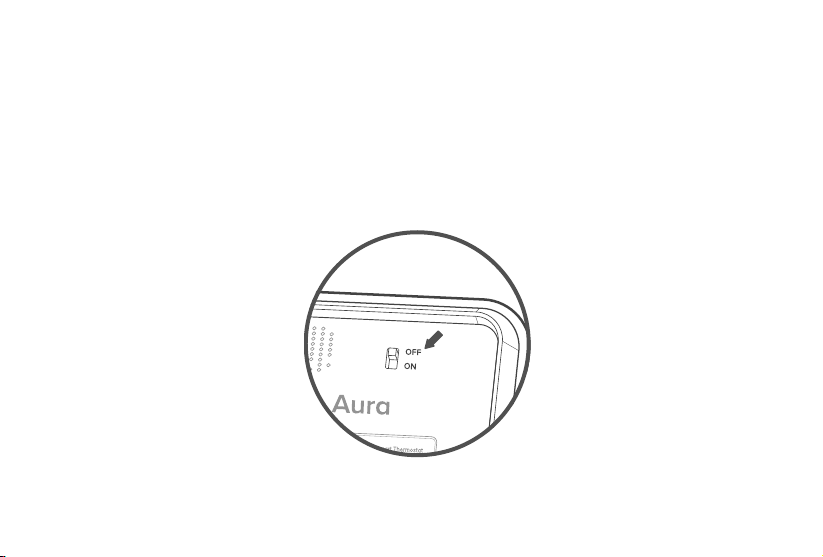
4. Adjust the jumper (DIP switch)
Turn the thermostat over. Adjust the jumper switch as follows [Figure 2.4]:
• If you have connected wires to both the Rc and Rh terminals on the backplate, then adjust the jumper switch to OFF.
• If not, then adjust the jumper switch to ON.
Figure 2.4
20
INSTALLING THERMOSTAT WITH A C WIRE (CONT.)
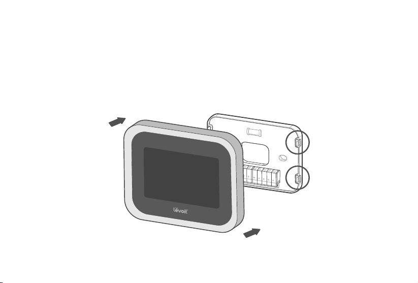
5. Place the thermostat
Make sure all wiring is pushed inside the wall. Carefully press the thermostat into the backplate until it clicks securely into
place. [Figure 2.5]
Note: Cover any gaps in the wall around the thermostat. Airow from holes may aect temperature readings.
Figure 2.5
21
INSTALLING THERMOSTAT WITH A C WIRE (CONT.)
6. Turn on your HVAC system
Turn your HVAC system back on. [Figure 2.6] If installation was successful, the thermostat display screen will turn on.
You are now ready to set up your thermostat (see Getting Started, page 41).
Note: If the thermostat display does not turn on, please see Troubleshooting, page 47.
TURN ON
Figure 2.6
Breaker Box
Switch
22
Installing Thermostat without a C Wire
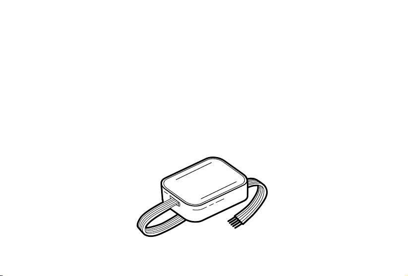
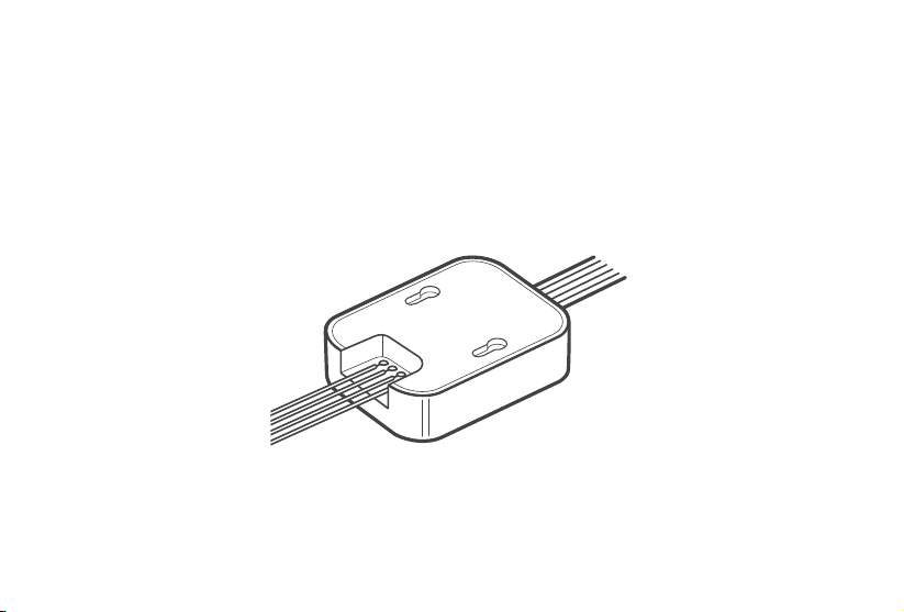
Power Extender Kit (PEK)
If your system does not have a C wire, you must install the power extender kit (PEK). The PEK connects to your thermostat
wires to create a circuit that provides power to your thermostat.
The PEK has 4 terminals on one side and 5 terminals on the other side.
• The side with 4 terminals is not pre-wired. Connect the thermostat wires to the terminals.
• The side with 5 terminals is pre-wired to connect to your HVAC control board.

23
Compatibility
The power extender kit (PEK) requires that your HVAC system has one of the following sets of wires:
If your HVAC does not have these wires, your system may not be compatible with the PEK.
4 Wires: W/W1, Y/Y1, G, and R (including Rc or Rh)
or
3 Wires: Y/Y1, G, and R (including Rc or Rh)
INSTALLING THERMOSTAT WITHOUT A C WIRE (CONT.)
24
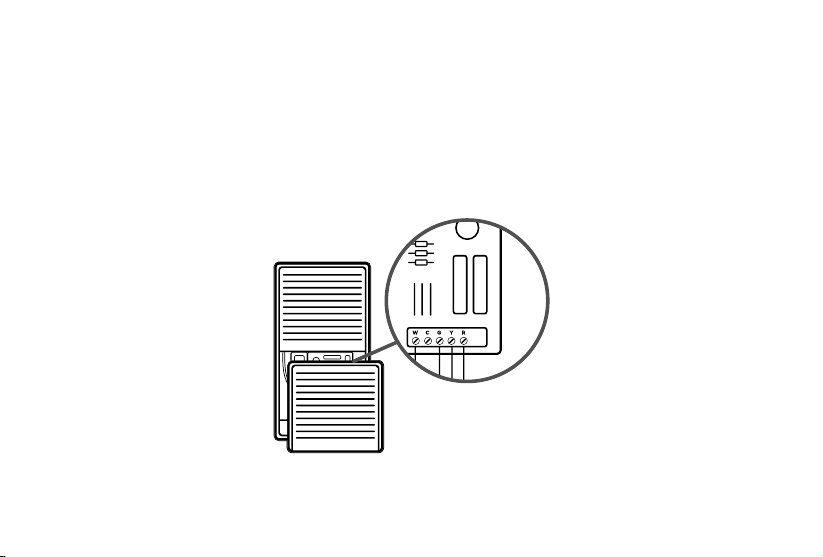
1. Identify the thermostat terminals on your HVAC
Find the control board of your HVAC system (typically, there is a cover you can pull
o to reveal the control board). [Figure 3.1]
Take a picture of the wires connected to the terminals that control your thermostat.
You may need to reference this photo later.
Figure 3.1
HVAC
Control Board
INSTALLING THERMOSTAT WITHOUT A C WIRE (CONT.)
25
INSTALLING THERMOSTAT WITHOUT A C WIRE (CONT.)
2. Label the thermostat wires
Find the PEK Labels in the included wire tag set. Use these to label
the wires on the HVAC’s control board according to the corresponding
terminals. [Figure 3.2]
Figure 3.2
To Thermostat
Control
Board
26
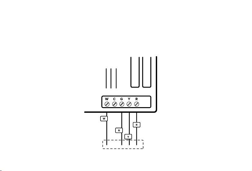
INSTALLING THERMOSTAT WITHOUT A C WIRE (CONT.)
3. Disconnect the thermostat wires
If you’re using 4 wires, carefully disconnect the W/W1, G, Y/Y1, and R
wires from the control board terminals. [Figure 3.3]
Note: If you’re only using 3 wires, you will only need to disconnect
the G, Y/Y1, and R wires.
Figure 3.3
To Thermostat
Control
Board
27
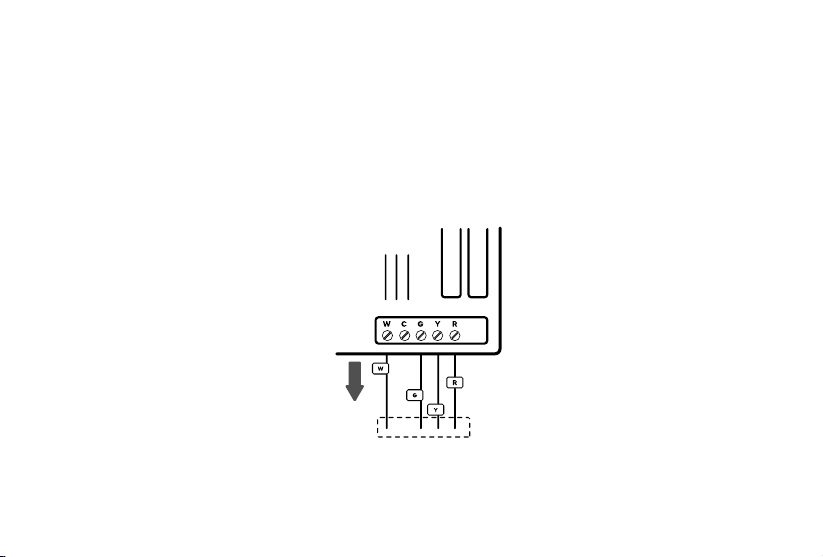
INSTALLING THERMOSTAT WITHOUT A C WIRE (CONT.)
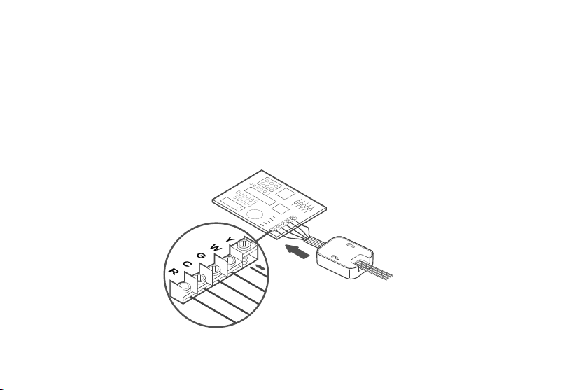
4. Connect the thermostat wires to the PEK
Connect the thermostat wires from the control board to the
corresponding terminals on the PEK. [Figure 3.4]
Figure 3.4
From Thermostat
To Control Board
28
INSTALLING THERMOSTAT WITHOUT A C WIRE (CONT.)
5. Connect the PEK wires to the control board
Connect the wires on the pre-wired side of the PEK (W, C, G, Y, and R wires)
to the corresponding 5 terminals on the control board. [Figure 3.5]
Figure 3.5
Take a picture of the wires connected to the PEK and the terminals on the control board.
You may need to reference this photo later.
29
INSTALLING THERMOSTAT WITHOUT A C WIRE (CONT.)
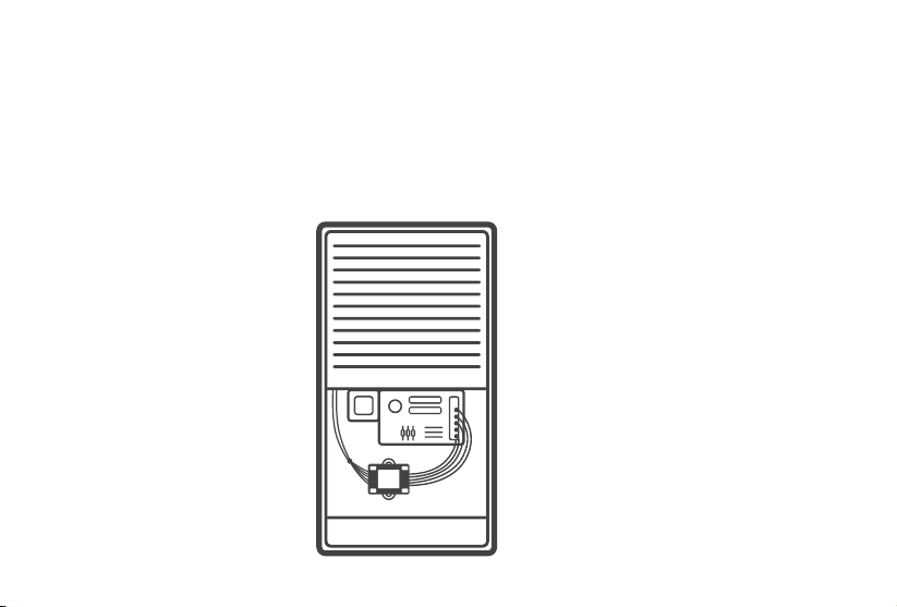
6. Position the PEK
The PEK should be securely placed between the thermostat wiring and the control board. [Figure 3.6]
Replace the cover on your HVAC system, then return to your thermostat.
Figure 3.6
30
INSTALLING THERMOSTAT WITHOUT A C WIRE (CONT.)
7. Remove the old backplate
Unscrew the old backplate from the wall. [Figure 3.7] Hold the wires and
carefully pull the backplate from the wall, making sure the wires do not
fall into the wall.
Figure 3.7
31
INSTALLING THERMOSTAT WITHOUT A C WIRE (CONT.)
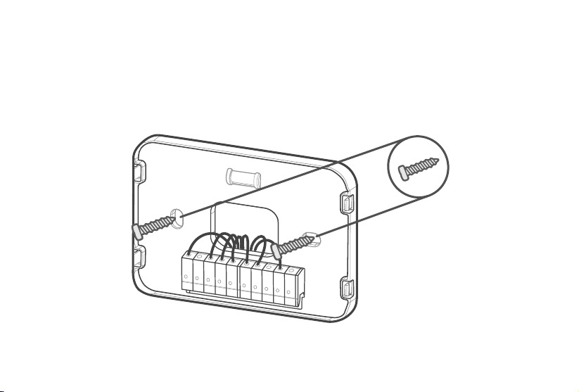
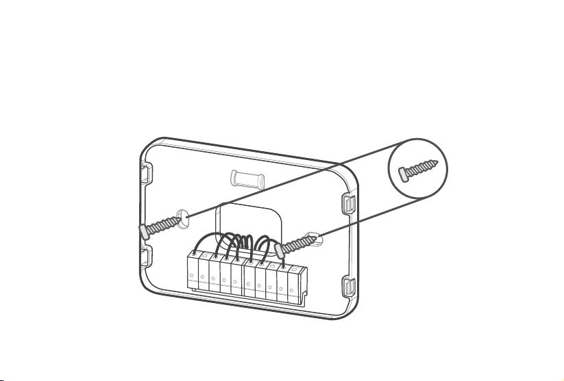
8. Attach the new backplate
Insert the wires through the hole in the new backplate. Use an electric
drill to attach the backplate to the wall with the provided wall anchors
and screws. [Figure 3.8]
Figure 3.8
32
INSTALLING THERMOSTAT WITHOUT A C WIRE (CONT.)
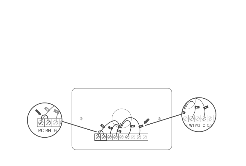
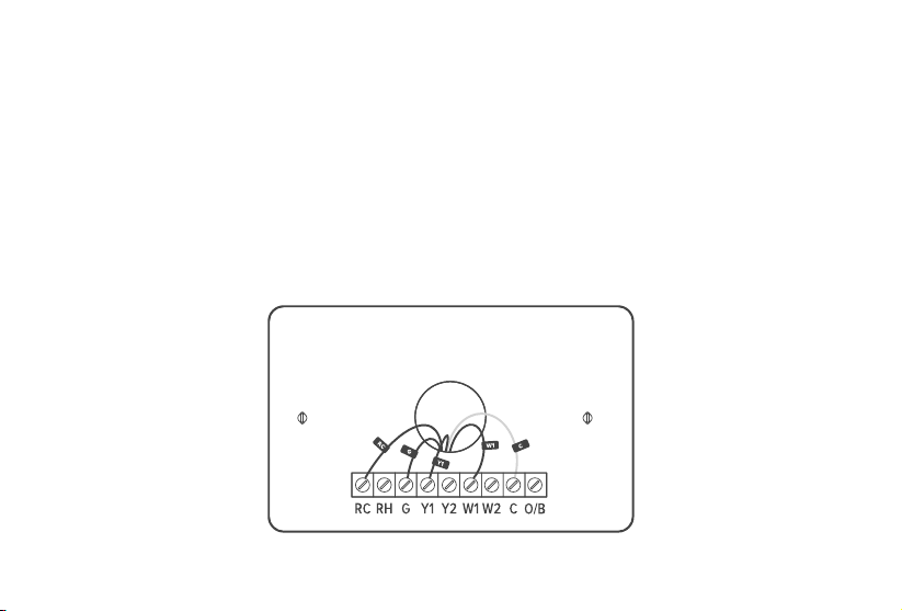
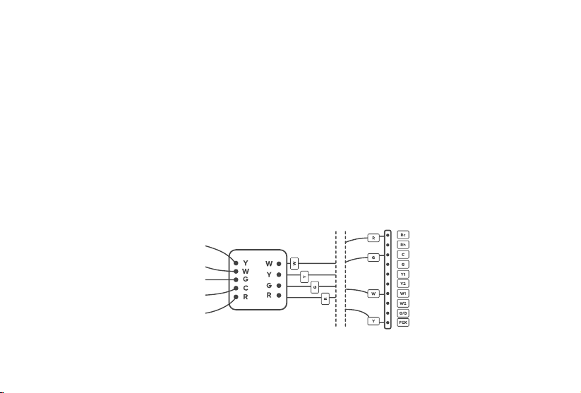
9. Connect the wires
First, connect the following 3 wires:
• R wire (R wires include R, Rc, and Rh) to the Rc terminal
• G wire to the C terminal
• Y/Y1 wire to the PEK terminal
Then, connect the remaining wires to the corresponding terminals on the backplate (see Wiring Diagrams, page 36).
[Figure 3.9] When you are finished, take a picture. You may need to refer to the connections in this photo while setting
up the thermostat.
Figure 3.9
Wall
PEK
Thermostat
33
INSTALLING THERMOSTAT WITHOUT A C WIRE (CONT.)
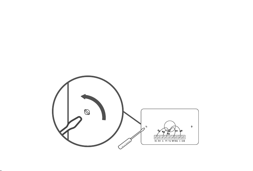
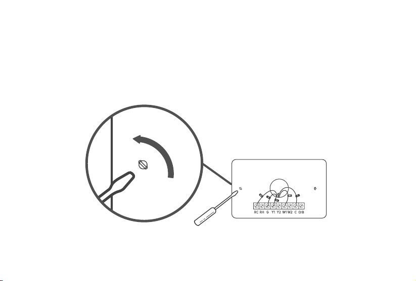
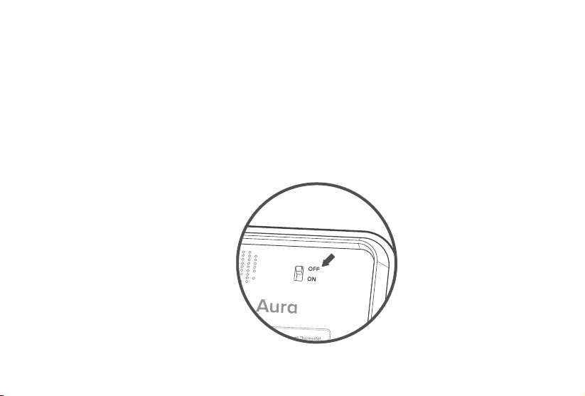
10. Adjust the jumper (DIP switch)
Turn the thermostat over. Adjust the jumper switch as follows [Figure 3.10]:
• If you have connected wires to both the Rc and Rh terminals on
the backplate, then adjust the jumper switch to OFF.
• If not, then adjust the jumper switch to ON.
Figure 3.10
34
INSTALLING THERMOSTAT WITHOUT A C WIRE (CONT.)
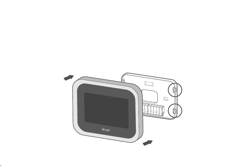
11. Place the thermostat
Make sure all wiring is pushed inside the wall. Carefully press the thermostat
into the backplate until it clicks securely into place. [Figure 3.11]
Note: Cover any gaps in the wall around the thermostat.
Airow from holes may aect temperature readings.
Figure 3.11

35
INSTALLING THERMOSTAT WITHOUT A C WIRE (CONT.)
12. Turn on your HVAC system
Turn your HVAC system back on. [Figure 3.12] If installation was successful, the thermostat display
screen will turn on. You are now ready to set up your thermostat (see Getting Started, page 41).
Note: If the thermostat display does not turn on, please see Troubleshooting, page 47.
TURN ON
Figure 3.12
Breaker Box
Switch

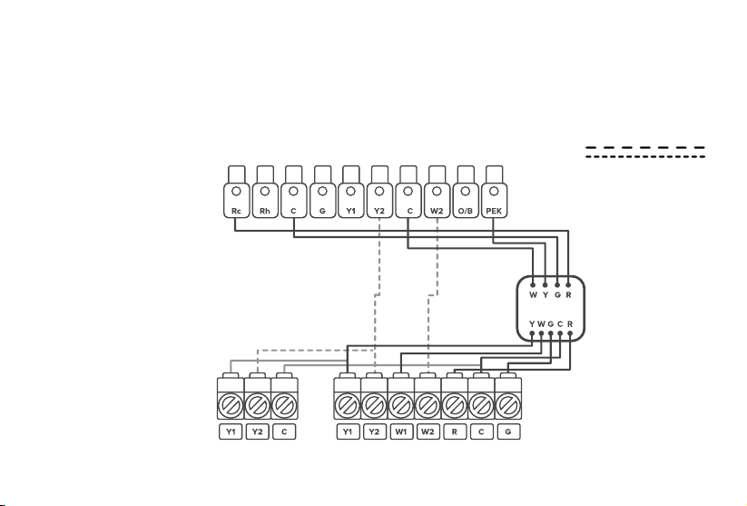
36
Wiring Diagrams
Conventional Heating/Cooling System - C Wire
The following are wiring diagrams for common HVAC systems. You may
be able to use these for reference when installing your thermostat.
Thermostat
Air Conditioner
HVAC
Furnace
For 2-Stage Heating/Cooling
Systems (If Applicable)
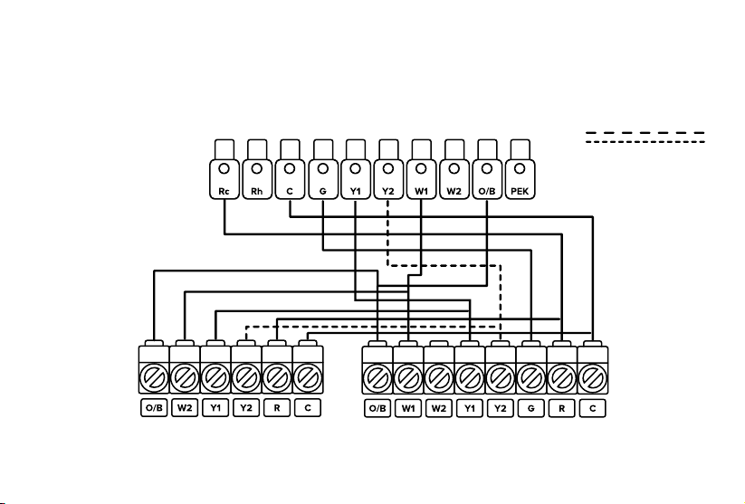
37
Thermostat
Air Conditioner
HVAC
Furnace
Conventional Heating/Cooling System - No C Wire (Used with PEK)
WIRING DIAGRAMS (CONT.)
For 2-Stage Heating/Cooling
Systems (If Applicable)
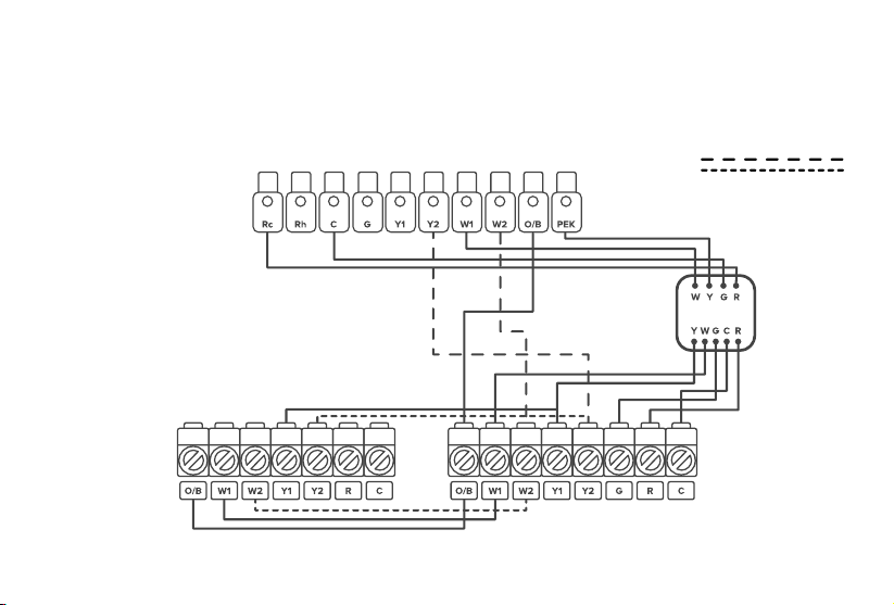
38
WIRING DIAGRAMS (CONT.)
Heat Pump (Air or Geothermal) with Auxiliary Heat - C Wire
Thermostat
Heat Pump Air Handler
HVAC
For 2-Stage Heating/Cooling
Systems (If Applicable)
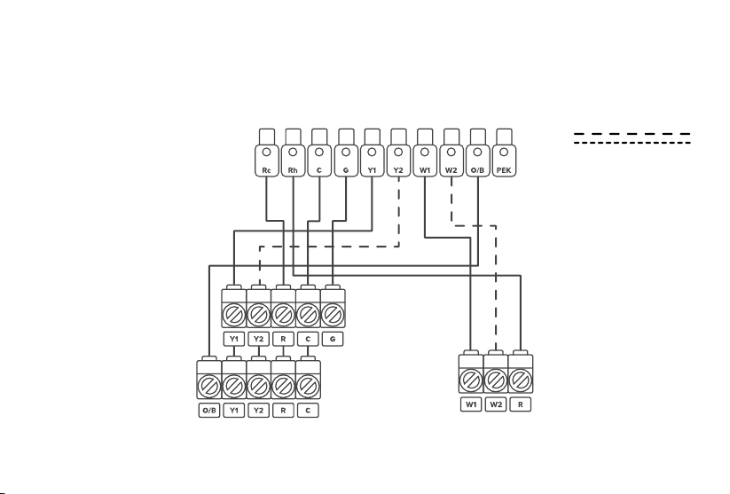
39
Heat Pump (Air or Geothermal) with Auxiliary Heat – No C Wire
(Used with PEK)
WIRING DIAGRAMS (CONT.)
Thermostat
Heat Pump Air Handler
HVAC
For 2-Stage Heating/Cooling
Systems (If Applicable)
40
WIRING DIAGRAMS (CONT.)
Heat Pump (Air or Geothermal) with Auxiliary Heat,
Two Transformer System – C Wire
Thermostat
Heat Pump/Air Conditioner
HVAC
Furnace/Boiler
For 2-Stage Heating/Cooling
Systems (If Applicable)

41
Note: Usually, the O/B engages when on cool.
3. Select the type of fuel system your furnace uses. This will aect how the fan works during heating.
Getting Started
Setup Wizard & Conguration
Note: The smart thermostat is continually being improved and may change over time. If there are any dierences,
follow the on-screen instructions.
1. When the thermostat first powers on, the welcome screen will appear. Begin the setup wizard.
2. Refer to the photo of the backplate terminals to find which terminals have wires connected to them, then select these
terminals on the screen.
• The thermostat will automatically determine what type of HVAC system you have.
• If there is a wire connected to the O/B terminal, that means that you have a heat pump system,
and a prompt will appear on-screen. Select how your O/B reversing valve is engaged.

42
4. Select your desired Eco Level.
5. Select whether you would like to connect the thermostat to the VeSync app (see VeSync App Setup,
page 45). If you don’t want to connect to VeSync right now, you can do it later.
• A higher Comfort level focuses on precise temperature control, but uses more energy.
• A higher Eco level focuses on energy eciency, but will not control temperature as precisely.
• If you are unsure what to select, choose “Balance.” This is a balance of Comfort and Eco.
GETTING STARTED (CONT.)
Note: Download the free VeSync app to control your smart thermostat remotely and use more functions
and features (see VeSync App Functions, page 46).
Note: This will set automatically if you are connected to the VeSync app.
6. Set your time zone and current time.
7. The setup wizard is complete. To start your thermostat, select an HVAC mode
(see HVAC Modes, on page 43).

43
Overview of Thermostat Modes
HVAC Modes:
Heat
Heating only
Smart
Automatically adjusts heating/cooling to reach
a single set target temperature.
Auxiliary Heat
Warms up the room faster if the heat pump
can’t warm up the room quickly enough.
Cool
Cooling only
O
Turns o heating and cooling. You can still use
the Fan Modes.
Auto
Automatically adjusts heating/cooling to
reach a target temperature range.

44
Fan Modes:
On/O
Turn the fan on/o.
Auto
Automatically adjusts fan based on the heating or
cooling mode.
Circulate
Turns fan on for 20 minutes every hour to circulate air.
OVERVIEW OF THERMOSTAT MODES (CONT.)
Important:
This user manual only includes installation and simple setup instructions.
For the extended digital manual, which includes full operating instructions
and a user guide, scan the QR code:
You can also type the following link into a web browser:
www.levoit.com/ltms401swus/downloads
45
VeSync App Setup
1. To download the VeSync app, scan the QR code
or search “VeSync” in the Apple App Store® or
Google Play Store.
3. Tap + and select your smart thermostat.
4. Follow the in-app instructions to set up your smart
thermostat.
2. Open the VeSync app. If you already have an
account, tap Log In. To create a new account, tap
Sign Up.
Note: The VeSync app is continually being
improved and may change over time. If there are
any dierences, follow the in-app instructions.
Note:
Note: For Android™ users, choose “Allow” to use
VeSync.
Note: You must create your own VeSync
account to use third-party services and products.
These will not work with a guest account. With a
VeSync account, you can also allow your family
and friends to control your smart thermostat.
• You can change the name and icon at any time
by going to the smart thermostat screen and
tapping .
• You can use the VeSync app to connect your
smart thermostat to Amazon Alexa or Google
Assistant™.

46
Connect with Amazon Alexa or Google Assistant™
Note: You must create your own VeSync account to access voice assistants.
VeSync App Functions
You can use the VeSync app to connect your smart thermostat to Amazon Alexa or Google Assistant™.
Please follow the in-app instructions to set up your voice assistant.
The VeSync app allows you to access additional smart thermostat functions, including those listed below. As
the app develops, more features may become available.
Remote Control
• Control your thermostat from anywhere using the
VeSync app.
• Connect your thermostat to third-party voice assistants.
Schedules
• Create and customize heating and cooling schedules
for every day of the week.
Smart Scenes
• Prioritize comfort and air quality in your home using
Smart Scenes, which can control your Levoit thermostat,
humidifier, and air purifier settings all at the same time.
Energy Usage Graphs
• View your thermostat energy usage and how much
time the thermostat spent heating/cooling.
• See your energy usage history for the previous week.
47
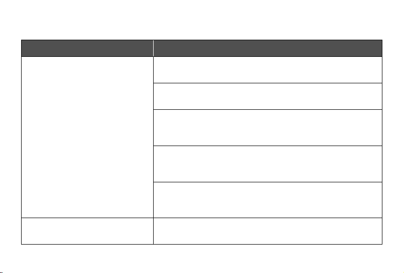
Troubleshooting
Problem Possible Solution
The thermostat display does not
turn on.
Gently tug on each wire connected to the terminals on the
backplate to make sure they are properly inserted and secure.
Make sure the cover of your HVAC system is completely closed.
Some HVAC systems do not turn on if the cover is not closed.
If you only have one R wire (R wires include R, Rc, and Rh), make
sure the R wire is connected to the Rc terminal (see About R
Wires, page 18).
If you are using the PEK, make sure the wires are connected to
the correct terminals on the backplate (see step 9 of Installing
Thermostat without a C Wire, page 32).
Use a multimeter to check the voltage of the C wire and Rc wire
to make sure it is AC 18–30V. The thermostat does not work with
high voltage systems. Contact Customer Support (see page 57).
The thermostat freezes or crashes. Remove the thermostat from the backplate, then reattach it.
This will restart the thermostat.
48
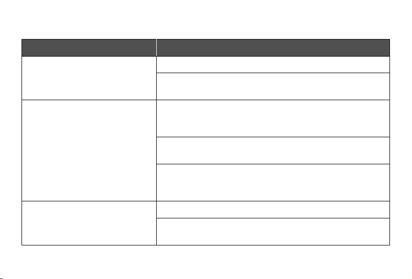
Problem Possible Solution
Forgot lock screen password. Unlock the thermostat through the VeSync app.
Remove the thermostat from the backplate, then reattach it. This
will restart the thermostat.
Heating and cooling functions are
reversed.
If you have a heat pump system, change the O/B reversing valve
setting in the thermostat’s settings (scan the QR code and see
Settings in the extended digital manual).
Make sure that the W wire and Y wire are connected to the correct
terminals on the backplate.
If you are using the PEK, make sure the wires are connected to the
correct terminals on the HVAC control board and backplate (see
Installing Thermostat without a C Wire, page 22).
The thermostat does not show
weather information.
Make sure the thermostat is connected to the VeSync app.
In the VeSync app, make sure you input your home location and
set the region to the United States.
TROUBLESHOOTING (CONT.)
49
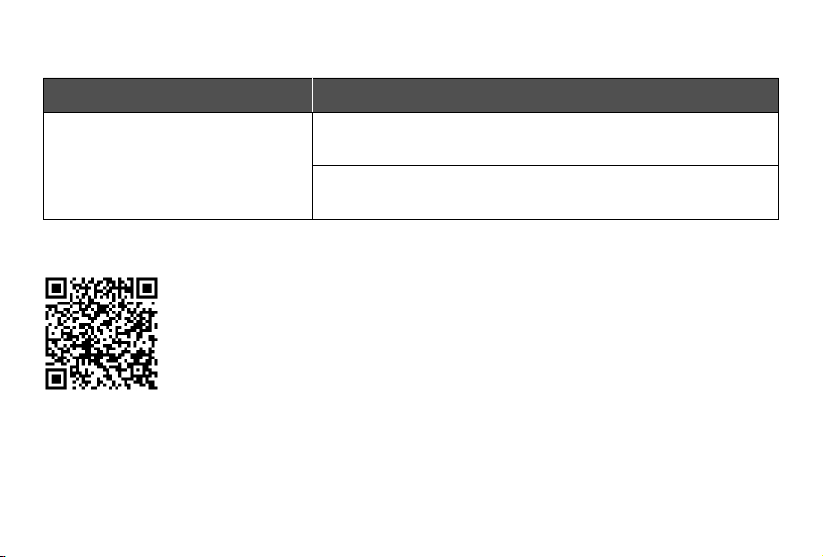
Problem Possible Solution
Room sensor (sold separately)
does not connect to the thermostat.
Make sure the thermostat and room sensor are added to the same
VeSync account.
One of the room sensor's batteries may be low.
Replace with 2 AAA batteries.
TROUBLESHOOTING (CONT.)
If your problem is not listed, please contact Customer Support (see page 57).
Important:
This user manual only includes
installation and simple setup
instructions. For the extended
digital manual, which includes full
operating instructions and a user
guide, scan the QR code.
You can also type the following link into a web browser:
www.levoit.com/ltms401swus/downloads

50
My smart thermostat isn’t connecting to the VeSync app.
• Make sure your phone has Bluetooth® turned on and is not currently connected to another Bluetooth device.
• During the setup process, you must be on a secure 2.4GHz Wi-Fi® network. Confirm that the network is working
correctly.
• Make sure the Wi-Fi password you entered is correct.
• There should be no spaces at the beginning or end of the password.
• Test the password by connecting a dierent electronic device to the router.
• If you’re manually typing in the SSID and password, double check that both are entered correctly.
• Your phone should be as close as possible to your thermostat.
• Your router may need to be at a higher location, away from obstructions.
• Make sure your thermostat and router are away from appliances (such as microwave ovens, refrigerators, electronic
devices, etc.) to avoid signal interference.
• If you’re using a VPN, make sure it’s turned o while setting up your thermostat.
• Disable portal authentication for your Wi-Fi network. If portal authentication is enabled, the thermostat will not be able
to access your Wi-Fi network, and setup will fail.
Note: Portal authentication means that you need to sign in to your Wi-Fi network through a web page
before you can use the Internet.
VeSync App Troubleshooting

51
VESYNC APP TROUBLESHOOTING (CONT.)
My thermostat is oine.
• Make sure your router is connected to the internet and your phone’s network connection is working.
• Delete your oine thermostat from the VeSync app. Swipe left (iOS®) or press and hold (Android™), then tap Delete
Reconfigure the thermostat with the VeSync app.
If your problem is not listed, please contact Customer Support (see page 57).
Note: Power outages, internet outages, or changing Wi-Fi routers may cause the thermostat to go oine.

52
FEDERAL COMMUNICATION COMMISSION INTERFERENCE STATEMENT -
PART 15
This device complies with Part 15 of the FCC Rules. Operation is subject to the following two conditions:
(1) This device may not cause harmful interference, and
(2) This device must accept any interference received, including interference that may cause undesired
operation.
NOTE: This equipment has been tested and found to comply with the limits for a Class B digital device,
pursuant to Part 15 of the FCC Rules. These limits are designed to provide reasonable protection against
harmful interference in a residential installation. This equipment generates, uses and can radiate radio
frequency energy and, if not installed and used in accordance with the instructions, may cause harmful
interference to radio communications. However, there is no guarantee that interference will not occur in
a particular installation. If this equipment does cause harmful interference to radio or television reception,
which can be determined by turning the equipment o and on, the user is encouraged to try to correct the
interference by one or more of the following measures:
• Reorient or relocate the receiving antenna.
• Increase the separation between the equipment and receiver.
• Connect the equipment into an outlet on a circuit dierent from that to which the receiver is
connected.
• Consult the dealer or an experienced radio/TV technician for help.

53
FCC Caution: Any changes or modifications not expressly approved by the party responsible for compliance
could void the user’s authority to operate this equipment.
FCC RADIATION EXPOSURE STATEMENT
FCC SDOC SUPPLIER’S DECLARATION OF CONFORMITY
This equipment complies with FCC radiation exposure limits set forth for an uncontrolled environment. End
users must follow the specific operating instructions for satisfying RF exposure compliance. To maintain
compliance with FCC RF exposure compliance requirements, please follow operation instructions as
documented in this manual. This transmitter must not be co-located or operating in conjunction with any other
antenna or transmitter. This equipment should be installed and operated with a minimum distance of 20cm
between the radiator and your body. The availability of some specific channels and/or operational frequency
bands are country dependent and are firmware programmed at the factory to match the intended destination.
The firmware setting is not accessible by the end user.
Arovast Corporation hereby declares that this equipment is in compliance with the FCC Part 15 Subpart
B. The declaration of conformity may be consulted in the support section of our website, accessible from
www.levoit.com.
54
Warranty Information
Terms & Policy
Arovast Corporation (“Arovast”) warrants this
product to the original purchaser to be free from
defects in material and workmanship, under
normal use and conditions, for a period of 2 years
from the date of original purchase.
Arovast agrees, at our option during the
warranty period, to repair any defect in material
or workmanship or furnish an equal product in
exchange without charge, subject to verification of
the defect or malfunction and proof of the date of
purchase.
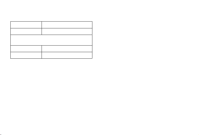
Product Name Aura™ Smart Thermostat
Model LTM-A401S-WUS
For your own reference, we strongly recommend
that you record your order ID and date of purchase.
Date of Purchase
Order ID
There is no other express warranty. This warranty does
not apply:
• If the product has been modified from its
original condition;
• If the product has not been used in accordance with
directions and instructions in the user manual;
• To damages or defects caused by accident, abuse,
misuse or improper or inadequate maintenance;
• To damages or defects caused by service or repair
of the product performed by an unauthorized
service provider or by anyone other than Arovast;
• To damages or defects occurring during commercial
use, rental use, or any use for which the product is
not intended;
• To damages or defects exceeding the cost of the
product.

55
Arovast will not be liable for indirect, incidental, or
consequential damages in connection with the use
of the product covered by this warranty.
This warranty extends only to the original
consumer purchaser of the product and is not
transferable to any subsequent owner of the
product regardless of whether the product is
transferred during the specified term of the
warranty.
This warranty does not extend to
products purchased from unauthorized
sellers. Arovast’s warranty extends only to
products purchased from authorized sellers that
are subject to Arovast’s quality controls and have
agreed to follow its quality controls.
All implied warranties are limited to the period of
this limited warranty.
This warranty gives you specific legal rights and you
may also have other rights which vary from state
to state. Some states do not allow the exclusion or
limitation of incidental or consequential damages, so
the above limitation or exclusion may not apply to you.
If you discover that your product is defective within
the specified warranty period, please contact
Customer Support via [email protected]. DO
NOT dispose of your product before contacting us.
Once our Customer Support Team has approved your
request, please return the product with a copy of the
invoice and order ID.
Every Levoit product automatically includes a 2-year
warranty. To make the customer support process
quick and easy, register your product online at
https://www.levoit.com/warranty.
WARRANY INFORMATION (CONT.)

56
This warranty is made by:
Arovast Corporation
1202 N. Miller St., Suite A
Anaheim, CA 92806
WARRANY INFORMATION (CONT.)
Attributions
Amazon, Alexa, and all related logos are trademarks of Amazon.com, Inc. or its aliates.
App Store® is a trademark of Apple Inc.
The Bluetooth® word mark and logos are registered trademarks owned by Bluetooth SIG, Inc. and any use
of such marks by Arovast Corporation is under license. Other trademarks and trade names are those of their
respective owners.
Google, Android, and Google Play are trademarks of Google LLC.
iOS is a registered trademark of Cisco Systems, Inc. and/or its aliates in the United States and certain other
countries.
Zigbee Alliance’s trademarks and logos, and all goodwill associated therewith, are the exclusive property of
the Zigbee Alliance.

57
Customer Support
If you have any questions or concerns about your
new product, please contact our helpful Customer
Support Team.
Arovast Corporation
1202 N. Miller St., Suite A
Anaheim, CA 92806
Support Hours
Mon–Fri, 9:00 am–5:00 pm PST/PDT
Email: [email protected]
Toll-Free: (888) 726-8520
*Please have your order invoice and order ID
ready before contacting Customer Support.
Notes

Notes

/LEVOITLIFESTYLE
/LEVOIT
/LEVOIT
/LEVOIT
LEVOIT.COM
A0-01.00_S 22D01 US