
MD21GS-3MP
00_MD21GS3MPINSTALLCOVER.P65 08/08/2005, 12:001

00_MD21GS3MPINSTALLCOVER.P65 08/08/2005, 12:002

Index
Warning ......................................................................................................................................... Japanese.1
Contents ....................................................................................................................................... Japanese.2
Quick Start ................................................................................................................................... Japanese.3
Display Adjustment & Mounting ............................................................................................... Japanese.4
User Controls ............................................................................................................................... Japanese.5
On-Screen Display ....................................................................................................................... Japanese.6
Advanced On-Screen Display .................................................................................................... Japanese.8
Self Calibration ........................................................................................................................... Japanese.10
White Point Matching/Copy Calibration ................................................................................ Japanese.12
Recommended Use...................................................................................................................... Japanese.14
Specifications .............................................................................................................................. Japanese.15
Features ........................................................................................................................................ Japanese.16
Troubleshooting .......................................................................................................................... Japanese.17
References.................................................................................................................................... Japanese.18
00_MD21GS3MPINSTALLCOVER.P65 08/08/2005, 12:003

Warning ......................................................................................................................................... English.1
Contents ....................................................................................................................................... English.2
Quick Start ................................................................................................................................... English.3
Display Adjustment & Mounting ............................................................................................... English.4
User Controls ............................................................................................................................... English.5
On-Screen Display ....................................................................................................................... English.6
Advanced On-Screen Display .................................................................................................... English.8
Self Calibration ........................................................................................................................... English.10
White Point Matching/Copy Calibration ................................................................................ English.12
Recommended Use...................................................................................................................... English.14
Specifications .............................................................................................................................. English.15
Features ........................................................................................................................................ English.16
Troubleshooting .......................................................................................................................... English.17
References.................................................................................................................................... English.18
Index
00_MD21GS3MPINSTALLCOVER.P65 08/08/2005, 12:004
Index
Warnung ........................................................................................................................................ Deutsch.1
Inhalt der Verpackung ............................................................................................................... Deutsch.2
Kurzanleitung .............................................................................................................................. Deutsch.3
Einstellung und Montage des Monitors ................................................................................. Deutsch.4
Einstellungen ............................................................................................................................... Deutsch.5
On-Screen Display ....................................................................................................................... Deutsch.6
Erweiterte OSD Einstellungen ................................................................................................. Deutsch.8
Selbstkalibrierung...................................................................................................................... Deutsch.10
Weißpunktabgleich/Kopierte Kalibrierung .......................................................................... Deutsch.12
Einsatzempfehlungen ................................................................................................................ Deutsch.14
Technische Daten ........................................................................................................................ Deutsch.15
Merkmale und Funktionen ........................................................................................................ Deutsch.16
Fehlerbehebung .......................................................................................................................... Deutsch.17
Referenz ........................................................................................................................................ Deutsch.18
00_MD21GS3MPINSTALLCOVER.P65 08/08/2005, 12:005

Index
Avertissement ............................................................................................................................. Français.1
Sommaire...................................................................................................................................... Français.2
Mise en marche rapide .............................................................................................................. Français.3
Ajustement et montage du moniteur .................................................................................... Français.4
Commandes utilisateur ............................................................................................................. Français.5
Affichage à l’écran ...................................................................................................................... Français.6
Affichage à l’écran avancé ........................................................................................................ Français.8
Calibrage auto ............................................................................................................................. Français.10
Calibrage de correspondance point blanc/de copie ........................................................... Français.12
Conseils d’utilisation.................................................................................................................. Français.14
Spécifications .............................................................................................................................. Français.15
Caractéristiques ......................................................................................................................... Français.16
Résolution des problèmes ......................................................................................................... Français.17
Références.................................................................................................................................... Français.18
00_MD21GS3MPINSTALLCOVER.P65 08/08/2005, 12:006

Index
Warning ......................................................................................................................................... Chinese.1
Contents ....................................................................................................................................... Chinese.2
Quick Start ................................................................................................................................... Chinese.3
Display Adjustment & Mounting ............................................................................................... Chinese.4
User Controls ............................................................................................................................... Chinese.5
On-Screen Display ....................................................................................................................... Chinese.6
Advanced On-Screen Display .................................................................................................... Chinese.8
Self Calibration ........................................................................................................................... Chinese.10
White Point Matching/Copy Calibration ................................................................................ Chinese.12
Recommended Use...................................................................................................................... Chinese.14
Specifications .............................................................................................................................. Chinese.15
Features ........................................................................................................................................ Chinese.16
Troubleshooting .......................................................................................................................... Chinese.17
References.................................................................................................................................... Chinese.18
00_MD21GS3MPINSTALLCOVER.P65 08/08/2005, 12:007
00_MD21GS3MPINSTALLCOVER.P65 08/08/2005, 12:008
EnglishEnglish
EnglishEnglish
English
DeutschDeutsch
DeutschDeutsch
Deutsch
FrançaisFrançais
FrançaisFrançais
Français
01A_ChapterOpener 08/08/2005, 12:001

01A_ChapterOpener 08/08/2005, 12:002
English.1
English
Power Cord Important Information
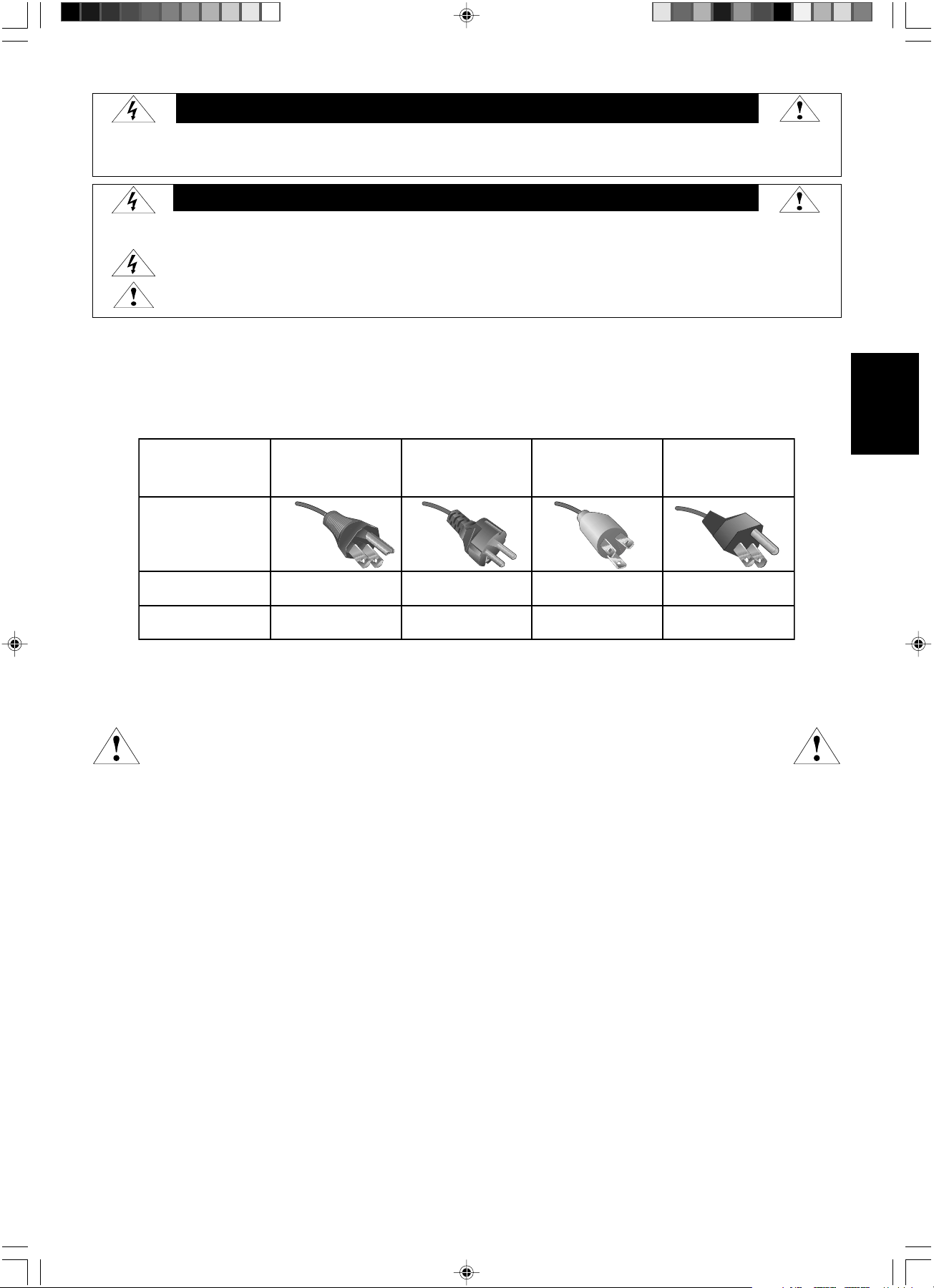
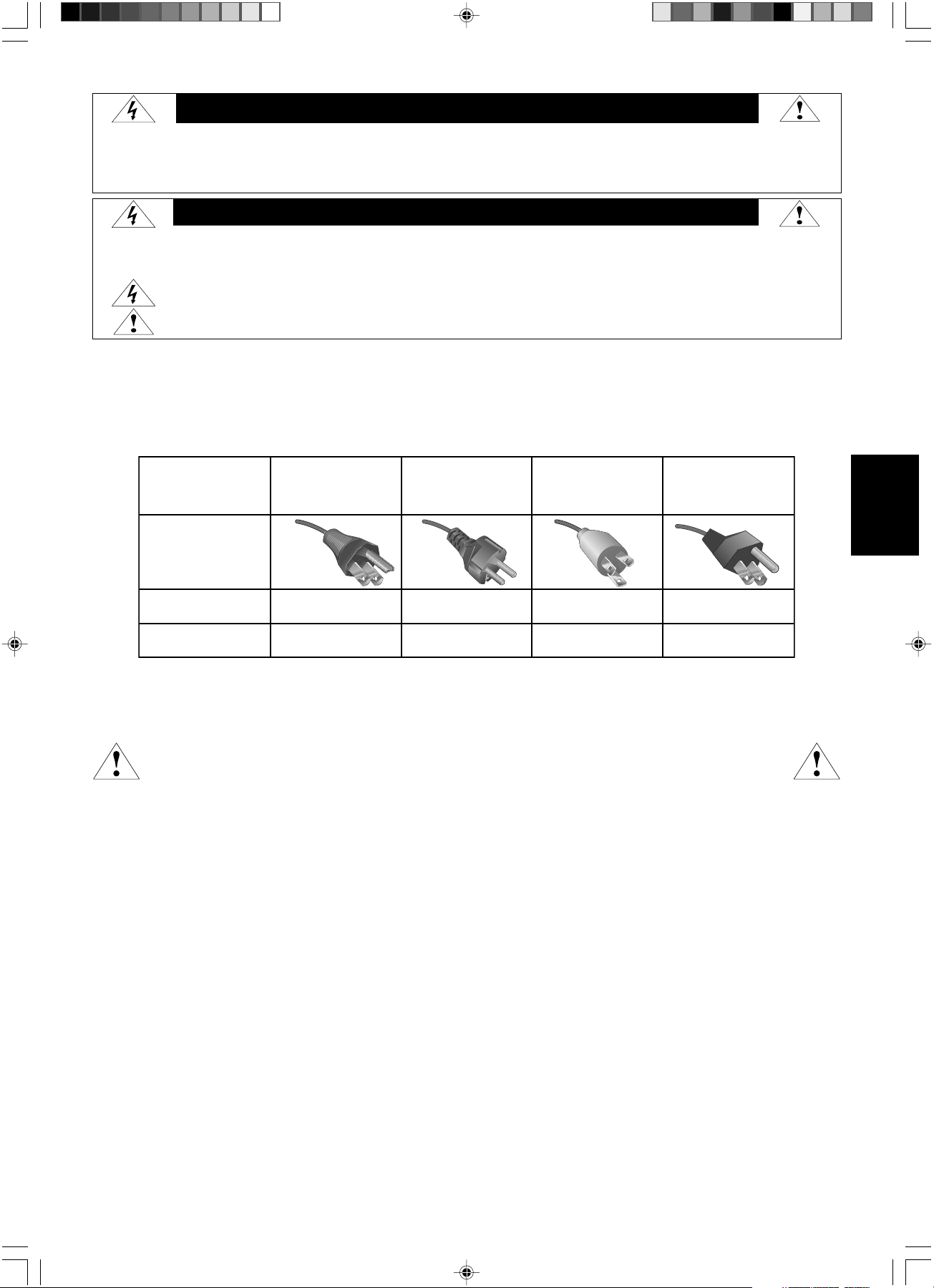
CAUTION: Please use the power cord provided with this display in accordance with the table below. If a power cord is not
supplied with this equipment, please contact your supplier. For all other cases, please use a power cord that matches the AC voltage of
the power outlet and has been approved by and complies with the safety standard of your particular country.
When you use this Display in North America, you should use a North America Hospital Grade power cord.
Intended Use
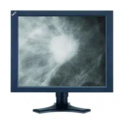
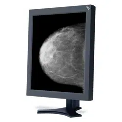
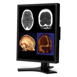
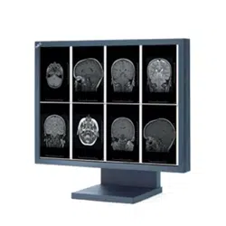
The MD21GS-3MP grayscale display is intended to be used for displaying and viewing of digital images for diagnosis by trained physicians.
To guarantee the display performance as specified, it must only be used in conjunction with NEC recommended display cards.
European Customers
Unpacking, Installation and calibration of this display should only be done by authorized and trained personnel.
Any installation done by a non-authorized person is done under his own risk and we accept no responsibility in
any device malfunctioning.
Medical Imaging
The NEC MD21GS-3MP is designed for 3-megapixel (1536 x 2048) grayscale medical imaging. This display comes fully tuned with a
setting for gamma correction that complies with the DICOM Part 14 Standard.
All brands and product names are trademarks or registered trademarks of their respective owners.
WARNING
TO PREVENT FIRE OR SHOCK HAZARDS, DO NOT EXPOSE THIS UNIT TO RAIN OR MOISTURE. ALSO, DO NOT USE THIS UNIT'S POLARIZED PLUG WITH
AN EXTENSION CORD RECEPTACLE OR OTHER OUTLETS UNLESS THE PRONGS CAN BE FULLY INSERTED.
REFRAIN FROM OPENING THE CABINET AS THERE ARE HIGH VOLTAGE COMPONENTS INSIDE. REFER SERVICING TO QUALIFIED SERVICE PERSONNEL.
TO REDUCE THE RISK OF ELECTRIC SHOCK, MAKE SURE POWER CORD IS UNPLUGGED FROM WALL SOCKET. TO FULLY DISENGAGE THE POWER
TO THE UNIT, PLEASE DISCONNECT THE POWER CORD FROM THE AC OUTLET. DO NOT REMOVE COVER (OR BACK). NO USER SERVICEABLE
PARTS INSIDE. REFER SERVICING TO QUALIFIED SERVICE PERSONNEL.
This
symbol warns user that uninsulated voltage within the unit may have sufficient magnitude to cause electric shock.
Therefore, it is dangerous to make any kind of contact with any part inside this unit.
This symbol alerts the user that important literature concerning the operation and maintenance of this unit has been included.
Therefore, it should be read carefully in order to avoid any problems.
CAUTION
CAUTION:
Plug Type European Continental Chinese
North America
Hospital Grade
Japanese
(for Japanese Market only)
Plug Shape
Country
Voltage
120 230 220 100
U.S.A./Canada EU (except U.K.) China Japan
(green dot
and tag label)
01_MD21GS3MPINSTALL_EN.P65 08/08/2005, 12:001
English.2
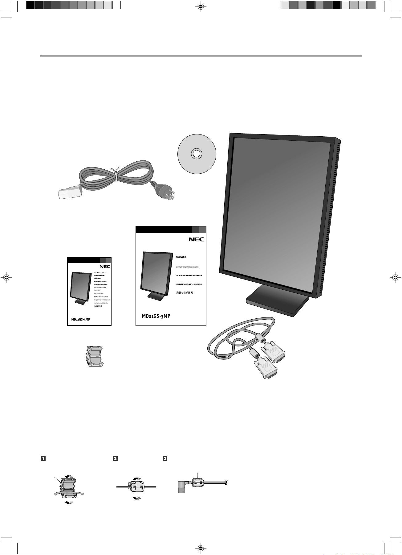
Your new NEC Display display box* should contain the following:
• MD21GS-3MP Display with tilt/swivel/pivot/height adjustable stand
• Power Cord
• Quick Reference Guide
• Installation and Maintenance Guide
• Video Signal Cable (DVI-D to DVI-D cable)
• Ferrite Core
*2
• CD-ROM
For complete display card instructions, please refer to the display card installation guide.
For GammaComp MD Quality Control Software, please refer to GammaComp MD User’s Guide.
* Remember to save your original box and packing material to transport or ship the display.
*
2
For Power Cord (European continental and Chinese type)
Contents
Power Cord
Video Signal Cable
Quick Reference Guide
Installation & Maintenance Guide
Ferrite Core
Open the ferrite core and damp
it on the power cord.
Close the ferrite core. Attach the Ferrite Core to the end of Power cord.
Only AC-IN (connector) side of display.
Ferrite Core
Ferrite Core
CD-ROM
01_MD21GS3MPINSTALL_EN.P65 08/08/2005, 12:002
English.3
English
Display Card Installation
1.
Following your PC manufacturer’s guidelines, open your computer to access the PCI, AGP or PCI E slot.
2. Place the display card into an available
PCI, AGP or PCI E
slot and secure all screws.
3. Replace the computer cover.
NOTE: For information on installing drivers, display modes in multimonitor mode, the setting the dip switches,
please refer to the display card manufacturer’s documentation.
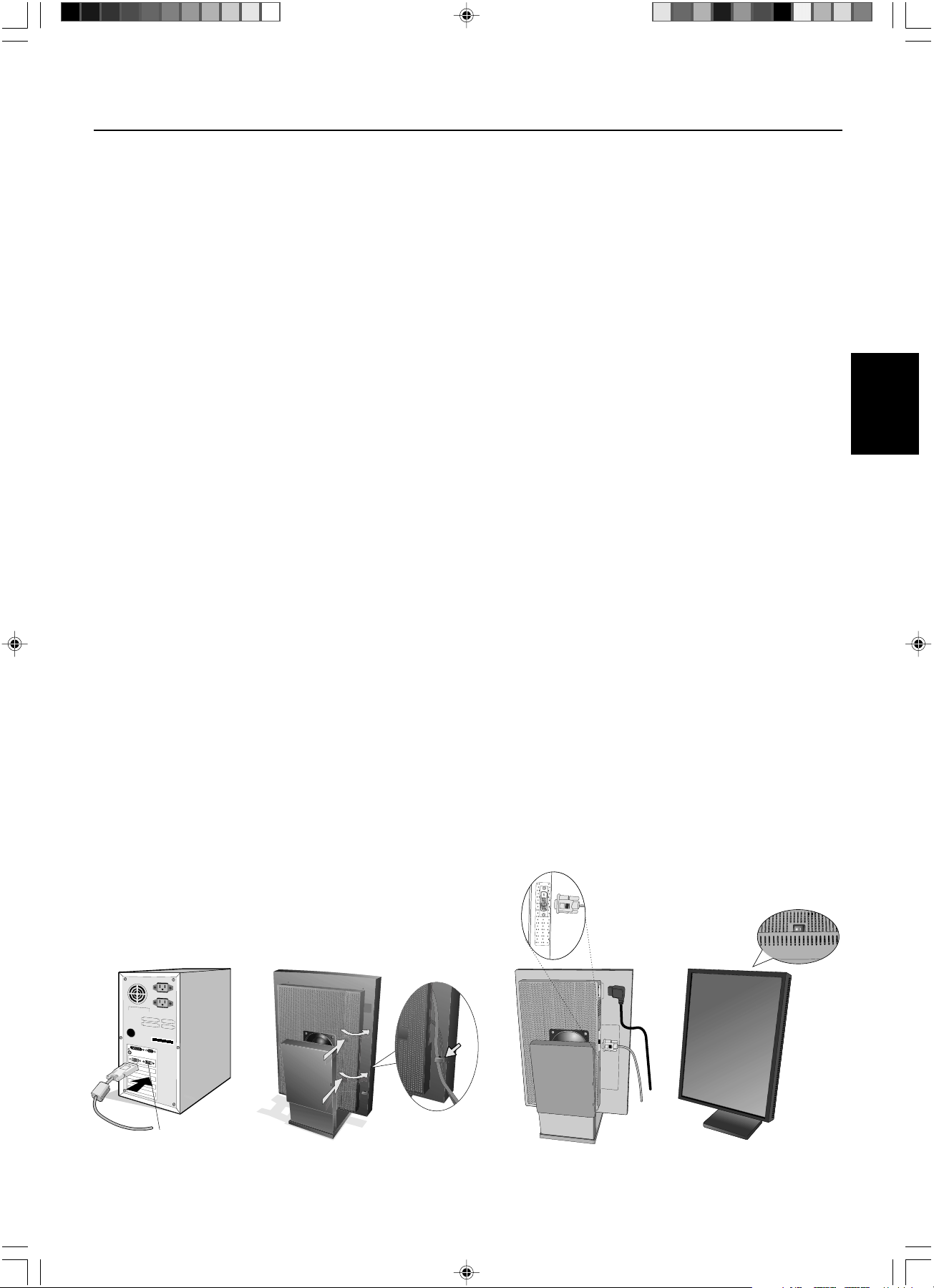
Connecting the LCD to Your PC
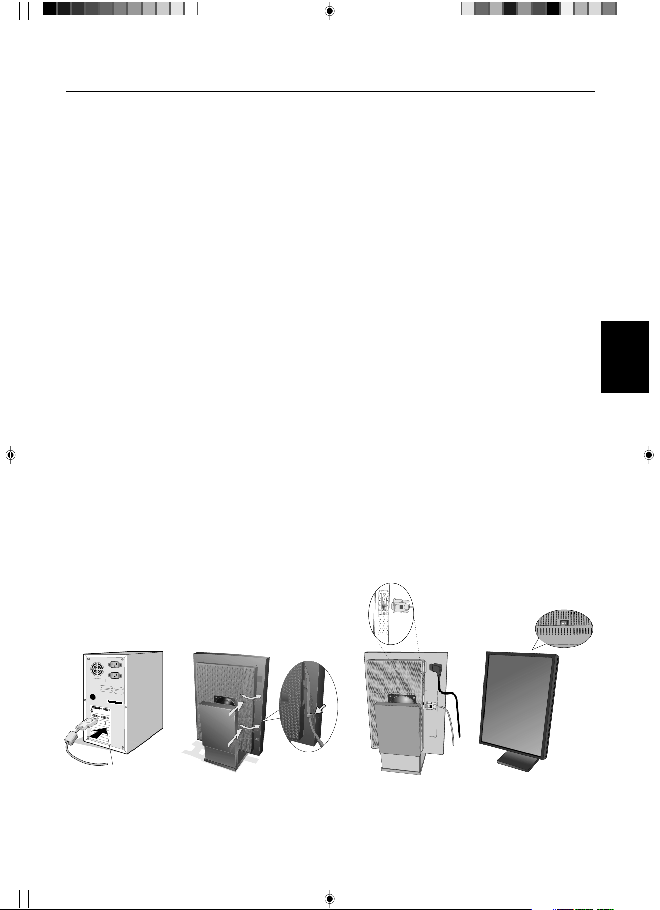
Once the display card is successfully installed, follow these instructions to connect the display to your PC.
1. Shut down your computer and turn off the power.
2. Connect the DVI-D signal cable to the connector of the display card in your system (Figure A.1).
NOTE: For dual displays, plug a DVI-D cables into Port 1 and Port 2 of the display card (Figure A.1).
For further information on display card installation, refer to the display card manual. Tighten all screws.
3. Remove the cable cover by pressing the two tabs to unlock. Lift the cover to remove (Figure B.1).
4. Connect the DVI-D signal cable to the connector on the back of the display (Figure C.1).
NOTE: Incorrect cable connections may result in irregular operation, damage display quality/components of LCD
module, and/or shorten the module life.
5. Connect one end of the power cord to the AC inlet on the back of the display and the other end to the power outlet
(Figure C.1). Replace the cable cover.
NOTE: Refer to the Display Adjustment & Mounting section to check tilt, raise and lower display screen and screen
rotation when you manage cables and power cord.
NOTE: Please refer to the Power Cord Important Information section of this manual for proper selection of AC power
cord.
6. Collect cables and power cord and place them under the cable clip (Figure B.1).
NOTE: Release the cables from the clip before removing the cable cover.
7. Turn on the display with the power switch on the top (portrait) or left side (landscape) of the display (Figure D.1).
Turn on the computer.
NOTE: DO NOT switch on/off repeatedly.
8. For further adjustments, please refer to the OSD section for a full description of OSD controls.
NOTE: If you have any problems, refer to the Troubleshooting section.
NOTE: External equipment intended for connection to signal input, signal output, or other connectors, must comply
with the relevant IEC standard.
Quick Start
Figure C.1
Figure A.1
Port 2 for Dual Display
Figure B.1
Figure D.1
Clip
01_MD21GS3MPINSTALL_EN.P65 08/08/2005, 12:003

English.4
Figure S.1
29mm
Display Adjustment & Mounting
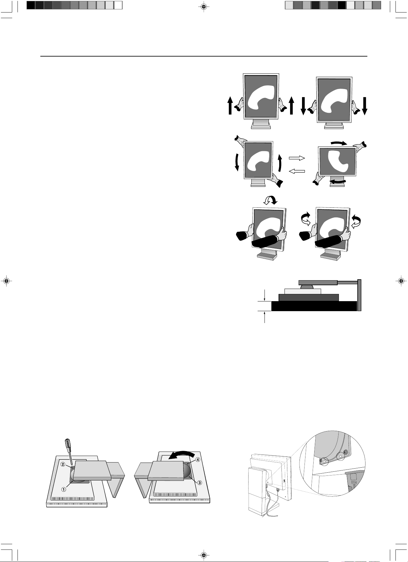
Raise and Lower Display Screen
The display may be raised or lowered in either portrait or land-
scape mode. To raise or lower the screen, place hands on each
side of the display and lift or lower to the desired height.
NOTE: Handle with care when raising or lowering the
display screen and avoid pinching your fingers.
Screen Rotation
Before rotating, the screen must be raised to the highest level to
avoid knocking the screen on the stand or pinching your fingers. To
rotate the screen, place hands on each side of the display screen and
turn clockwise from landscape to portrait or counterclockwise from
portrait to landscape. To rotate the orientation of the OSD menu
between landscape and portrait, refer to the “OSD” section,
“OSD Rotation” function.
Tilt and Swivel
Grasp the left and right sides of the display screen with your hands and
adjust the tilt and/or swivel as desired. NOTE: Handle with care when
tilting the screen.
Alternative VESA LCD Mounting
1. Disconnect all cables.
2.
Place hands on each side of the display and lift up to the highest position.
Rotate the screen 90˚ counterclockwise to the landscape postion.
3. Place display face down on a nonabrasive surface in the landscape
position. Place the screen on at least a 29 mm platform so that the
stand is parallel with the surface (Figure S.1).
4. Remove the two top screws connecting the display to the stand (Figure S.2).
Turn the stand to 180˚ counter clockwise (you will hear two clicks).
Remove the screws from the bottom (Figure S.3) and lift off the stand. The display is now ready for mounting in an
alternate manner.
5. Reverse this process to reattach stand: tighten the two bottom screws, turn stand 180˚ counterclockwise (you will hear
two clicks), and tighten two top screws.
NOTE: Use only VESA-compatible alternative mounting method (100mm pitch).
NOTE: Handle with care when removing the display stand.
NOTE: When the
display
is in landscape, be sure the two round indents are at the bottom of the screen (Figure S.4).
CAUTION: Use the original screws (4 pcs) when mounting to avoid damage to the display and stand. To fulfill the safety
requirements the display must be mounted to an arm which guaranties the necessary stability under consideration of the
weight of the display. The display can only be used with an approved arm (e.g. GS mark).
Figure S.4Figure S.3Figure S.2
01_MD21GS3MPINSTALL_EN.P65 08/08/2005, 12:004
English.5
English
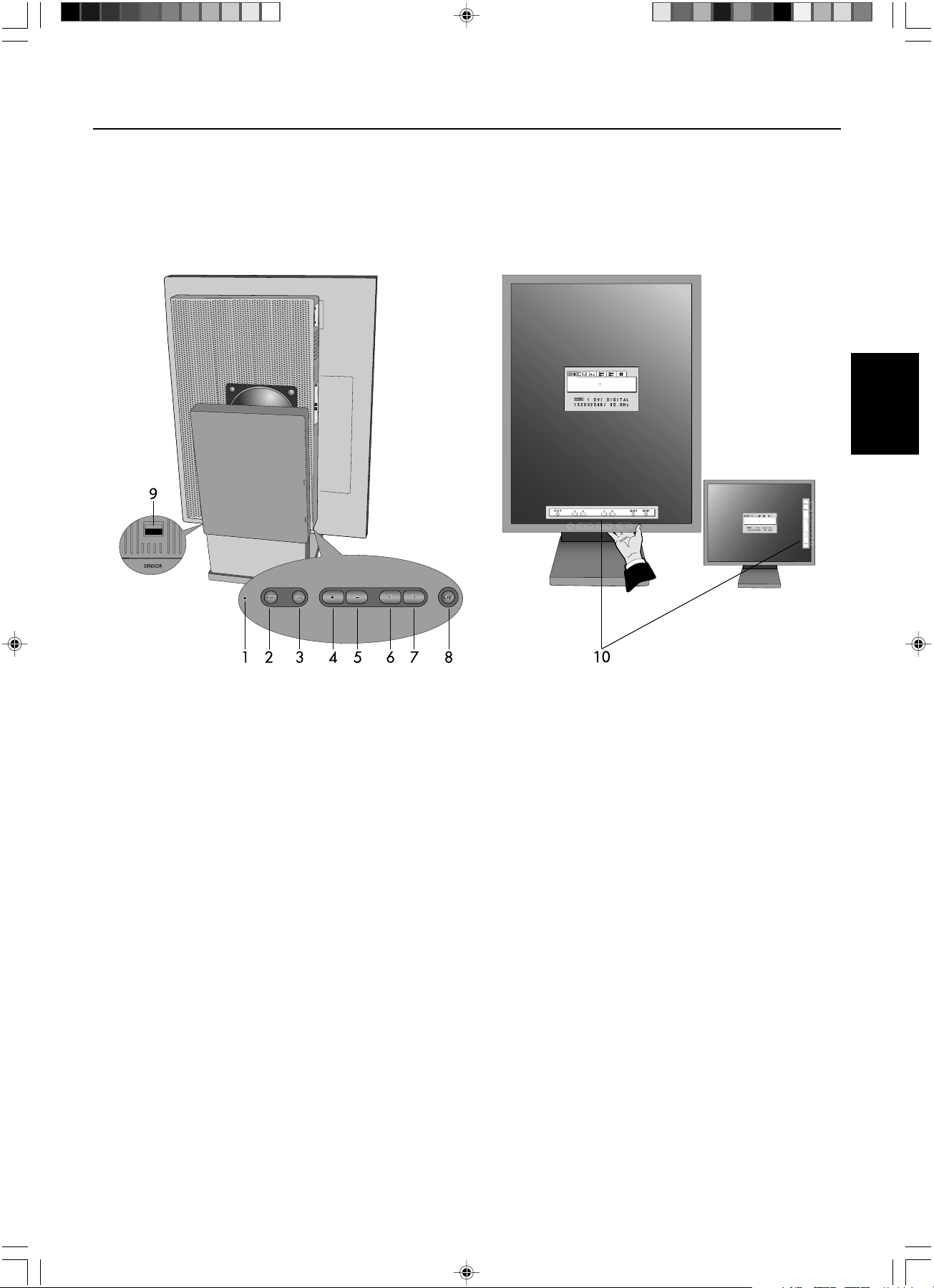
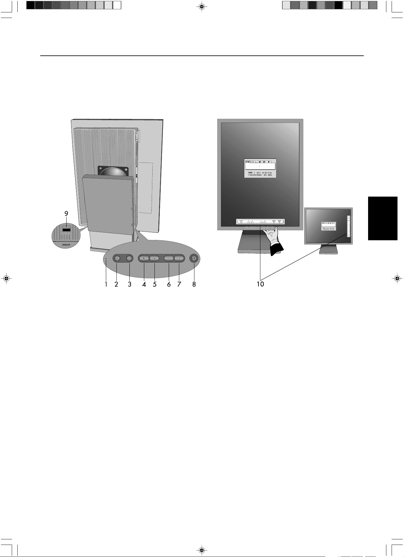
User Controls
The On-Screen Display (OSD) control buttons are located on the back of the display. To access the OSD menu, press any of
the user control buttons ( < , >, –, +).
1. LED Indicates power on and signal condition. The LED can be turned on, off, or dimmed. Please
refer to the Advanced OSD section/LED Brightness for further information.
Green – signal is present and power is on
Orange – no signal
2. RESET Resets the highlighted control menu to the factory setting.
3. SELECT Enters the OSD controls and OSD sub menu.
4/5. ADJUST -/+ Moves the bar left/right to increase or decrease the adjustment.
6/7. CONTROL </> Moves the highlighted area left/right to select control menus.
Moves the highlighted area up/down to select one of the controls.
8. EXIT Exits the OSD Controls and OSD Main Menu.
9. Sensor Port For optional external sensor used for self calibration and copy calibration.
10. On-Screen The key guide will automatically appear on the screen when any control button on the
Key Guide back is pressed. The key guide will change orientation along with the OSD.
NOTE: When RESET is pressed in the main and sub-menu, a warning window will appear allowing you to cancel the
RESET function by pressing the EXIT button.
Portrait Mode
Landscape Mode
01_MD21GS3MPINSTALL_EN.P65 08/08/2005, 12:005
English.6
On-Screen Display
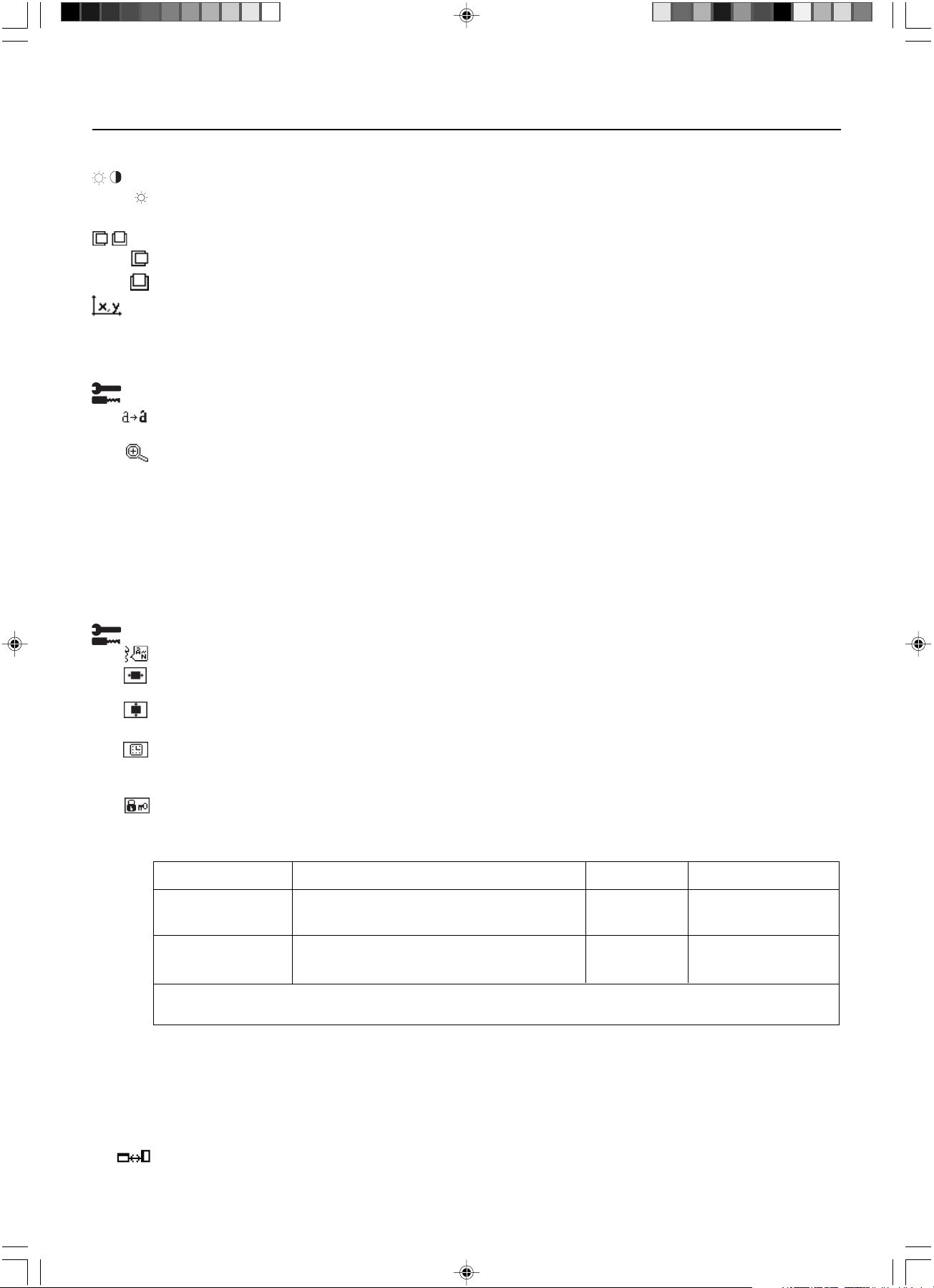
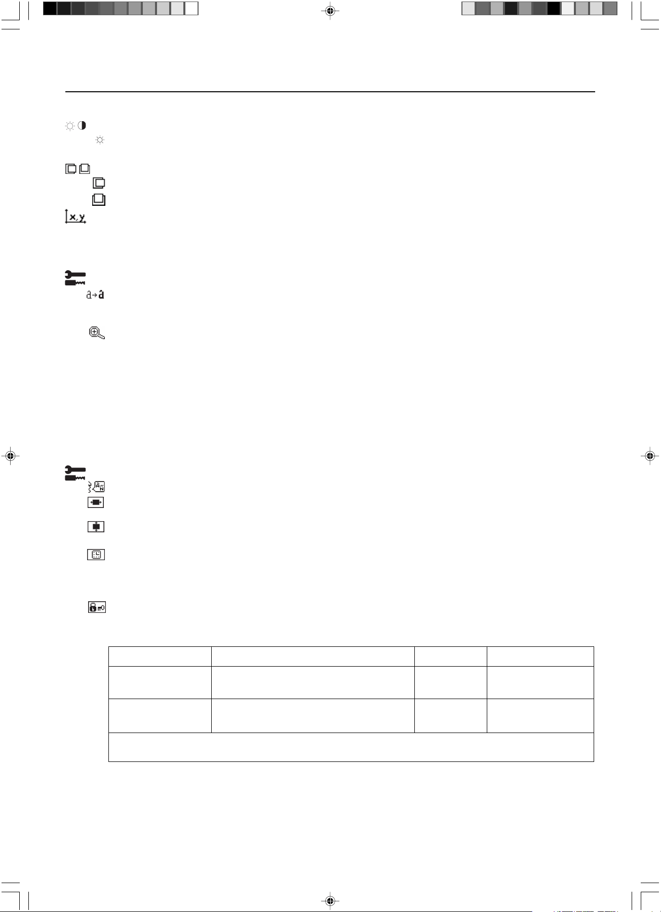
Brightness
BRIGHTNESS: Adjusts the overall image and background screen brightness. When BRIGHTNESS is adjusting, the
numerical value blinks.
Position Control (except Packed Pixel mode/10 bit)
LEFT/RIGHT: Controls the Horizontal Image Position within the display area.
DOWN/UP: Controls the Vertical Image Position within the display area.
White Point Selection
DEFAULT: preset factory white point selection (Clear Base or Blue Base depending on model)..
COPIED WHITE: White point set using copy calibration.
NATIVE: Preset native white point of the display. The maximum brightness setting is available.
Tools 1
SHARPNESS: This function digitally adjusts the display for crisp images. If the factory setting is not sufficient, the
image is manually adjustable. This function works when the GRAYSCALE BIT is set 8bit.
EXPANSION MODE: Sets the zoom method.
FULL: The image is expanded to 1536 x 2048 regardless of the resolution.
ASPECT: The image is expanded without changing the aspect ratio.
OFF: The image is not expanded.
CUSTOM (Resolution of 1536 x 2048 only): Zoom with center fixed. Select one of nine expansion rates. In
this mode the resolution may be low and show blank areas. This mode is for use with special display cards.
GRAYSCALE BIT: Select the GRAYSCALE BIT (8 or 10bit) of the display card.
8 bit – 256 shades of gray
10 bit – 1024 shades of gray
Tools 2
LANGUAGE: OSD control menus are available in seven languages.
OSD LEFT/RIGHT: You can choose where you would like the OSD control image to appear on your top half of
screen. Selecting OSD Location allows you to manually adjust the position of the OSD control menu left or right.
OSD DOWN/UP: You can choose where you would like the OSD control image to appear on your top half of
screen. Selecting OSD Location allows you to manually adjust the position of the OSD control menu down or up.
OSD TURN OFF: The OSD control menu will remain on screen as long as it is use. In the OSD Turn Off submenu,
you can select how long the display waits after the last touch of a
button to shut off the OSD control menu. The preset
choices are 10-120 seconds in 5 second intervals.
OSD LOCK OUT: This control locks out access to all or some OSD control functions. When attempting to activate
OSD controls while in the Lock Out mode, a screen will appear indicating the OSD controls are locked out.
There are three types of OSD LOCK OUT:
OSD LOCK OUT with no control: To activate the OSD Lock Out function, press SELECT, then “>” key and hold
down simultaneously. To deactivate the OSD Lock Out, press SELECT, then “>” key and hold down simulta-
neously while in the OSD menu. No controls can be adjusted while in the lock out mode.
OSD LOCK OUT with BRIGHTNESS control: To activate the OSD Lock Out function, press SELECT, then “–” and
”<“ key and hold down simultaneously. To deactivate the OSD Lock Out, press SELECT, then “–” and “<“ key
and hold down simultaneously while in the OSD menu. BRIGHTNESS can be adjusted while in the lock out mode.
OSD ROTATION: To rotate OSD between landscape and portrait modes. Use the + or – key to change the
orientation of the OSD and On-screen Key Guide.
GRAY
BIT
MODE Key strokes to enter BRIGHTNESS LOCK OUT Warning
OSD LOCK OUT SELECT, > No Yes
with no control
OSD LOCK OUT SELECT, – , < Yes Yes
with BRIGHTNESS
For CUSTOM LOCK OUT option, please refer to the Advanced OSD section.
01_MD21GS3MPINSTALL_EN.P65 08/08/2005, 12:006
English.7
English
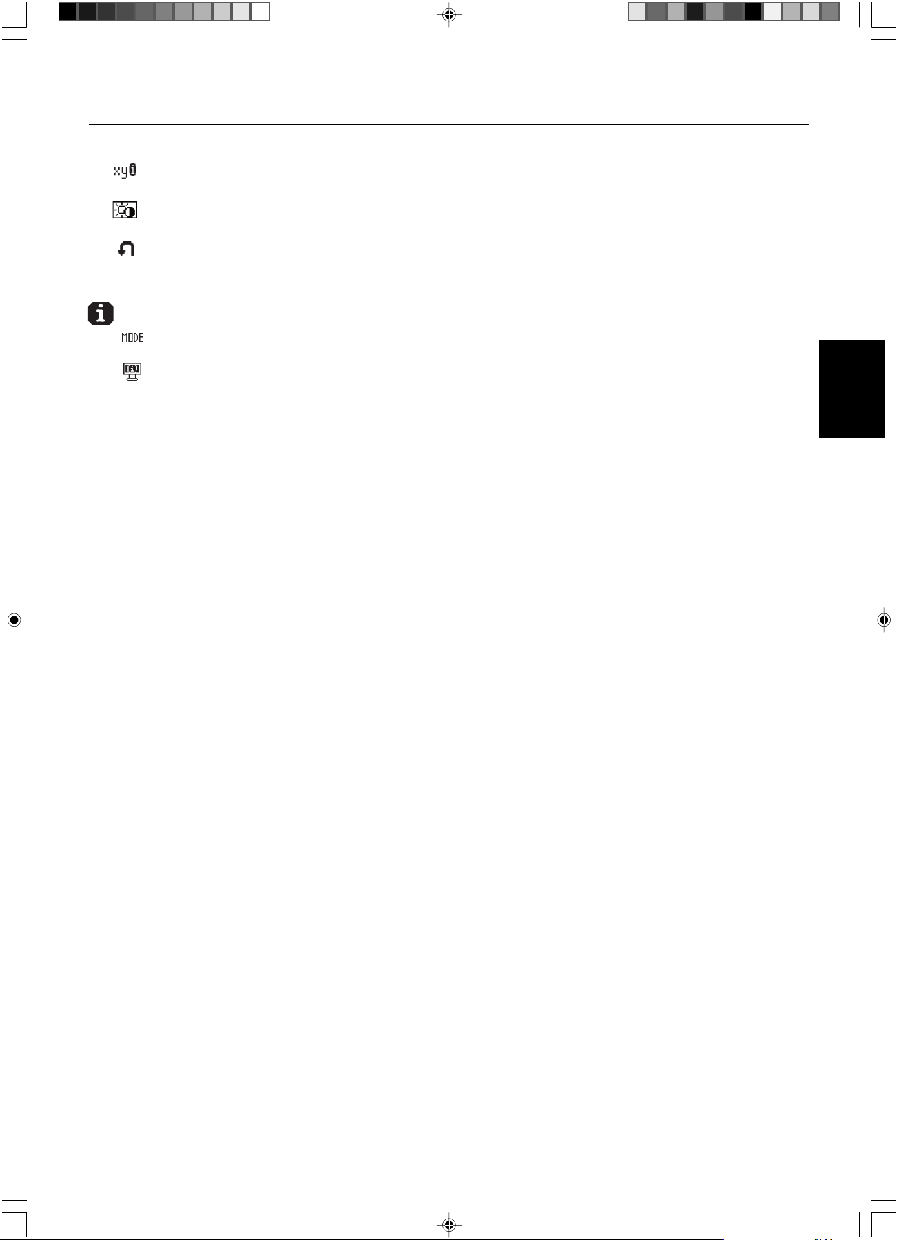
On-Screen Display –continued
RESOLUTION NOTIFIER: This optimal resolution is 1536 x 2048. If ON is selected, a message
will appear on the
screen after 30 seconds, notifying you that the resolution is not at
1536 x 2048
.
HOT KEY: You can adjust the brightness directly. When this function is set to ON, you can adjust the brightness
with <, >, +, or –, while the OSD menu is off. The standard OSD can be accessed with the EXIT button.
FACTORY PRESET: Selecting Factory Preset allows you to reset all OSD control settings (BRIGHTNESS, POSITION
CONTROL, WHITE POINT SELECTION, SHARPNESS, EXPANSION MODE, OSD LEFT/RIGHT, OSD
DOWN/UP, OSD TURN OFF, DISPLAY MODE) back to the factory settings. Individual settings can be reset by
highlighting the control to be reset and pressing the RESET button.
Information
DISPLAY MODE: Provides information about the current resolution display and technical data including the preset
timing being used and the horizontal and vertical frequencies.
MONITOR INFO.: Indicates the model and serial numbers of your display.
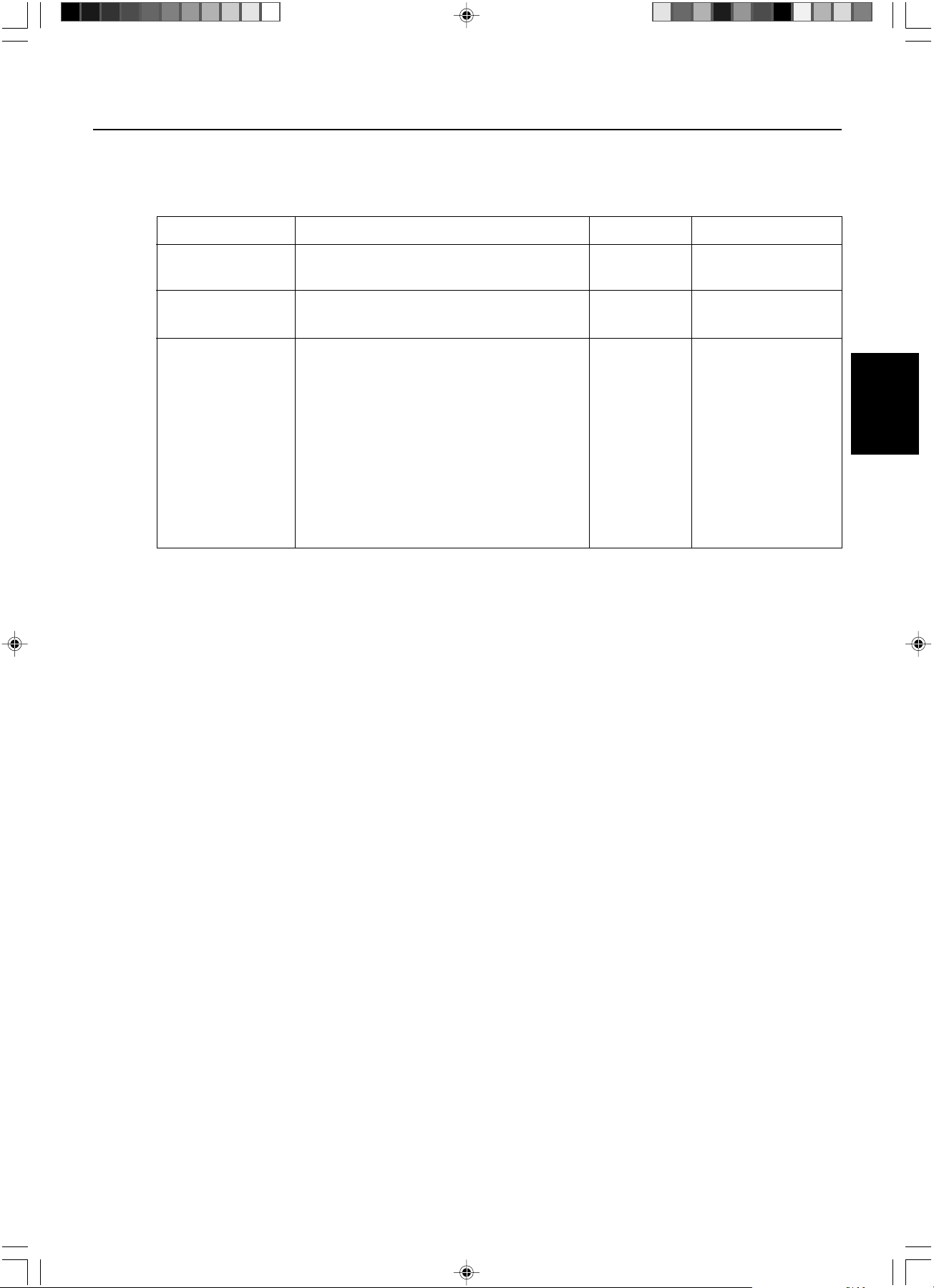
OSD Warnings
To clear the on-screen warning, press the EXIT button.
NO SIGNAL: This function gives a warning when there is no Horizontal or Vertical Sync. After power is turned on
or when there is a change of input signal, the No Signal window will appear.
RESOLUTION NOTIFIER: This function gives a warning of use with optimized resolution. After power is turned on
or when there is a change of input signal or the video signal doesn’t have proper resolution, the Resolution
Notifier window will open. This function can be disabled in the TOOLS 2 menu.
OUT OF RANGE: This function gives a recommendation of the optimized resolution and refresh rate. After the
power is turned on or there is a change of input signal or the video signal doesn’t have proper timing, the Out Of
Range menu will appear.
OSD LOCK OUT: This function indicates that the OSD function has been locked by the user. This can be disabled
using the CUSTOM LOCK OUT menu.
LAMP LIFETIME: At 1000/500/0 hours, the OSD warning will be displayed. The display cannot hold user set
luminance levels, however, white point will be maintained. Please contact your supplier when this OSD warning
is displayed.
BRIGHTNESS WARNING: This function indicates when the BRIGHTNESS setting cannot be complete.
01_MD21GS3MPINSTALL_EN.P65 08/08/2005, 12:007

English.8
Advanced On-Screen Display
The Advanced OSD offers more control over the standard OSD controls. When OSD is off, push the “RESET” and “EXIT”
button at the same time to activate the Advanced OSD. NOTE: This menu is larger than the normal OSD. To make an
adjustment, ensure that the tag is highlighted, then press “SELECT”. To move to another tag, press “EXIT” and then press
“<“ or “>” to highlight another tag.
Tag1
Brightness
Adjusts the overall image and screen background brightness using the numeric value. Press “+” or “-” to
adjust.
When BRIGHTNESS is adjusting, a numerical value blinks.
Tag2
This tag is not adjustable.
Tag3
H. Position Controls Horizontal Image Position within the display. Press “+” or “-” to adjust.
V. Position Controls Vertical Image Position within the display. Press “+” or “-” to adjust.
Tag4
Gamma Selection
Allows you to manually select the brightness level of grayscale. There are five selections:
NO CORRECTION, DICOM, LOG LINEAR, CUSTOM, and PROGRAMMABLE.
1. NO CORRECTION
2. DICOM: DICOM GSDF (Grayscale Standard Display Function) is possible. DICOM LUT is calculated
based on the calibration data at factory for each individual display.
3. LOG LINEAR: Luminance changes log rhythmically in response to a linear change of gradation.
4. CUSTOM: The gamma value is selected from a range of 0.5 to 4.0 by 0.1 intervals.
5.
PROGRAMMABLE
: The brightness of grayscale can be changed by using the GammaComp MD Software.
Gamma Offset Adjusts the black level of the gamma setting. NOTE: DICOM is not adjustable.
Tag5
White Point Selection
DEFAULT: preset factory white point selection (Clear Base or Blue Base depending on model)..
COPIED WHITE: White point set using copy calibration.
NATIVE: Preset native white point of the display. The maximum brightness setting is available.
Tag6
Self Test Mode Displays an all white screen. Used for white point matching/copy calibration.
Lamp Lifetime Estimates the life of the lamp. Lifetime depends upon luminance calibration setting.
Temperature Displays internal display temperature and internal backlight sensor temperature.
BRIGHTNESS Displays target and current luminance levels in cd/m
2
.
INFO
Tag7
Sharpness This function is digitally adjusts the display for crisp images. If the factory setting is not sufficient, the image
is manually adjustable. This function works when the GRAYSCALE BIT is 8bit.
Expansion Mode
Sets the zoom method.
FULL: The image is expanded to 1536 x 2048, regardless of the resolution.
ASPECT: The image is expanded without changing the aspect ratio.
OFF: The image is not expanded.
CUSTOM (1536x2048 only): Zoom with center fixed. Select one of nine expansion rates. In this mode the
resolution may be low and show blank areas. This mode is for use with special display cards.
Grayscale Bit Select the GRAYSCALE BIT, 8 or 10bit.
Language OSD control menus are available in seven languages. Press “+” or “–” to select.
OSD Left/Right
You can choose where you would like the OSD control image to appear on your top half of screen.
Selecting OSD location allows you to manually adjust the position of the OSD control menu left or right.
OSD Down/UP
You can choose where you would like the OSD control image to appear on your top half of
screen.
Selecting OSD location allows you to manually adjust the position of the OSD control menu down or up.
OSD Turn Off The OSD control menu will stay on as long as it is use. In the OSD Turn Off submenu, you can select how
long the display waits after the last touch of a
button to shut off the OSD control menu. The preset choices are
10-120 seconds in 5 second intervals.
01_MD21GS3MPINSTALL_EN.P65 08/08/2005, 12:008
English.9
English
Advanced On-Screen Display –continued
OSD Lock Out This control completely locks out access to all OSD control functions. When attempting to activate OSD
controls while in the Lock Out mode, a screen will appear indicating the OSD controls are locked out.
There are three types of OSD LOCK OUT:
OSD LOCK OUT with no control: To activate the OSD Lock Out function, press SELECT, then “>” key
and hold down simultaneously. To deactivate the OSD Lock Out, press SELECT, then “>” key and hold
down simultaneously while in the OSD menu. No controls can be adjusted while in the lock out mode.
OSD LOCK OUT with BRIGHTNESS control: To activate the OSD Lock Out function, press SELECT,
then “–” and ”<“ key and hold down simultaneously. To deactivate the OSD Lock Out, press SELECT,
then “–” and ”<“ key and hold down simultaneously while in the OSD menu. BRIGHTNESS can be
adjusted while in the lock out mode.
CUSTOM: Press RESET and EXIT to enter the CUSTOM Menu. Select ENABLE or DISABLE for
BRIGHTNESS or WARNING (RESOLUTION NOTIFIER/OSD LOCK OUT).
OSD Rotation To switch OSD between Landscape and Portrait modes. Press “+” or “–” to select.
Resolution Notifier
The optimal resolution is 1536 x 2048. If ON is selected, a message will appear on the screen after 30
seconds, notifying you that the resolution is not set to 1536 x 2048. Press “+” or “–” to select.
HOT KEY You can adjust the brightness directly. When this function is set to ON, you can adjust the brightness with <,
>, +, or –, while the OSD menu is off. The standard OSD can be accessed with the EXIT button.
LED Brightness Controls the brightness of the LED on the display, “OFF”, “MID” and “MAX”.
Factory Preset
Selecting Factory Preset allows you to reset all OSD control settings (BRIGHTNESS, H.Position, V.Position,
Gamma Selection, Gamma Offset, WHITE POINT SELECTION, SHARPNESS, EXPANSION MODE, OSD
LEFT/RIGHT, OSD DOWN/UP, OSD TURN OFF, SELF CALIBRATION, DISPLAY MODE) back to the factory
settings. Individual settings can be reset by highlighting the control to be reset and pressing the RESET button.
Tag8
This tag is not adjustable.
Tag9
Display Mode Provides information about the current display resolution and technical data, including the preset timing
currently being used and the horizontal and vertical frequencies. Increases or decreases the current
resolution. Press “SELECT” to move the adjustment mode, and press “+” or “–” to adjust horizontal and
vertical resolution.
Monitor Info. Indicates the model and serial numbers of your display.
MODE Key strokes to enter BRIGHTNESS LOCK OUT Warning
OSD LOCK OUT SELECT, > No Yes
with no control
OSD LOCK OUT SELECT, – , < Yes Yes
with BRIGHTNESS
CUSTOM LOCK OUT 7 step process to Activate: Selectable Selectable
1. Press RESET and EXIT to enter Advanced OSD
2. Press < to reach Tag 7
3. Highlight the OSD LOCK OUT function
4. Press RESET and EXIT
5. ENABLE or DISABLE: BRIGHTNESS, WARNING
6. Press SELECT to enter the OSD LOCK OUT mode
7. Press EXIT to exit the OSD
To Deactivate:
1. Without OSD menu, press RESET and EXIT to bring
up the LOCK OUT warning
2. Press SELECT, SELECT, <, >, <, >, EXIT
01_MD21GS3MPINSTALL_EN.P65 08/08/2005, 12:009
English.10
Use GammaComp MD Quality Control Software for history management (Constancy test).
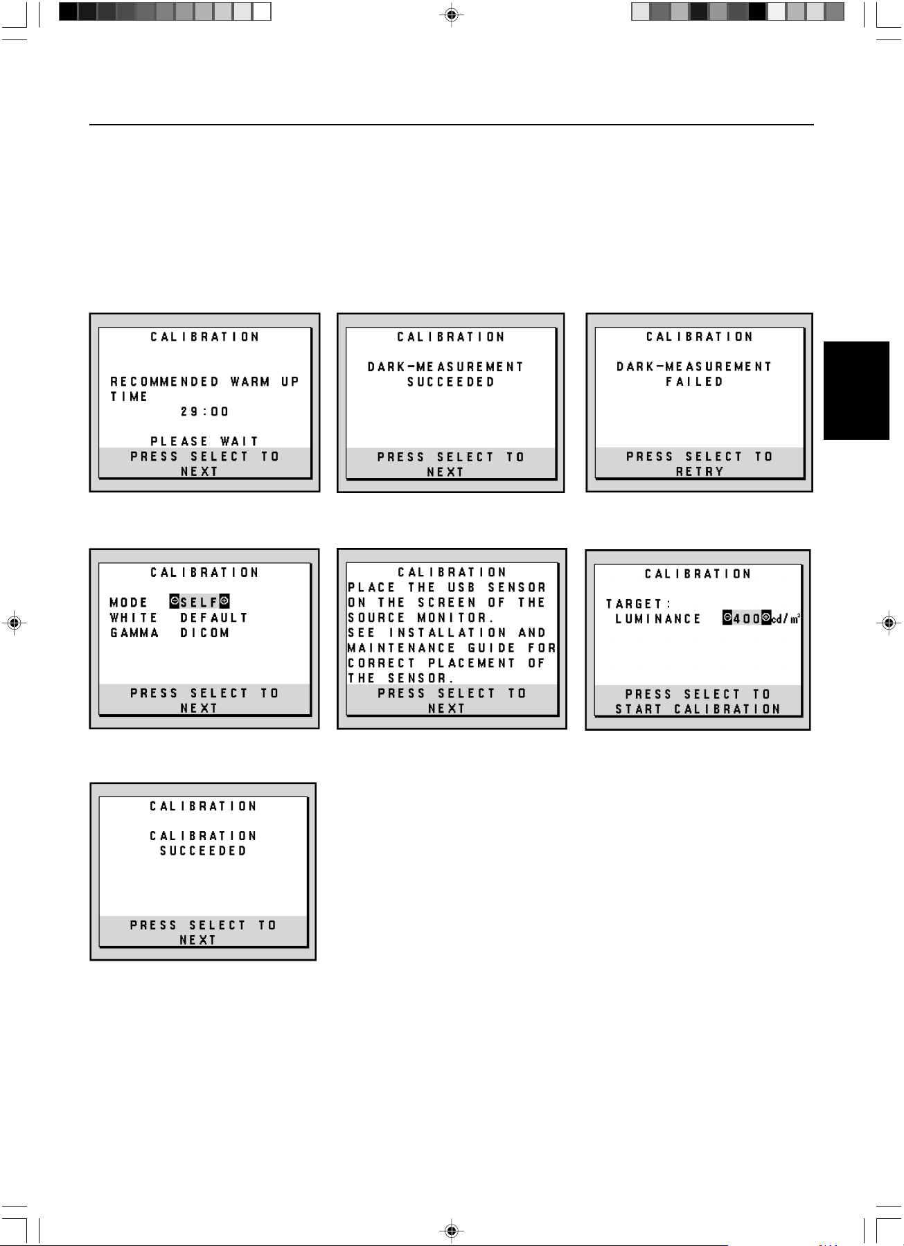
Before proper self calibration can be
performed, display should warm-up for a minimum 30 minutes. If the USB sensor is plugged in before the minute warm-up,
a warning will appear on-screen (Figure S.3). NOTE:
Stand-alone calibration can only be performed using the
GretagMacbeth Eye-One Display Sensor.
Refer to the KEY MAP (Figure A) when changing settings during the calibration.
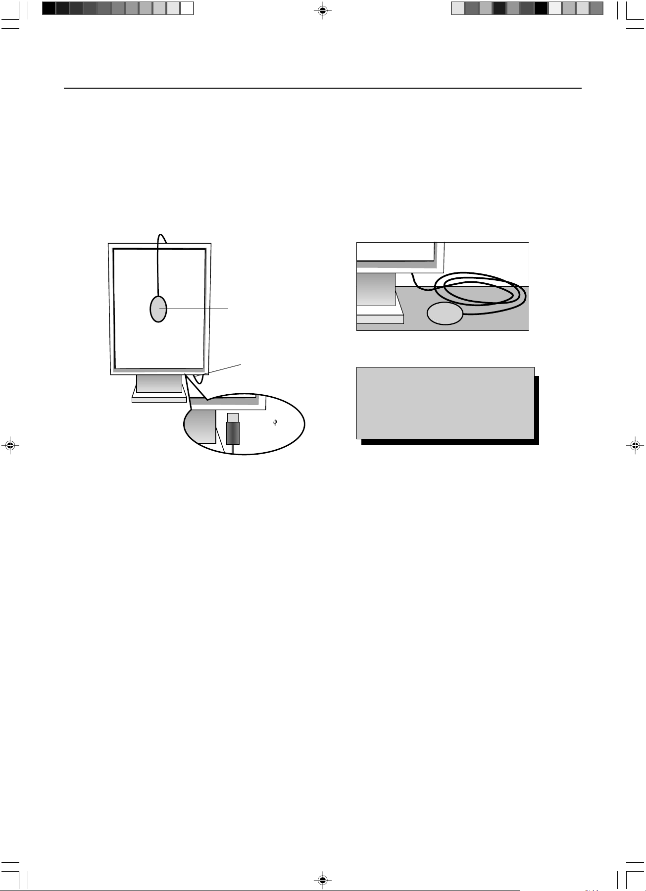
1. Plug-in the USB sensor to the sensor port (Figure S.1).
NOTE: Sensor port can only be used for the sensor connection.
2. The calibration menu will open automatically and the sensor will begin to initialize. After initializing, the DARK-
MEASUREMENT message is displayed. If the DARK-MEASUREMENT message is not displayed, please proceed to step 5.
3. Place the USB sensor face down on a non-reflective, opaque surface (ie...desk or a mousepad) to measure the black
level (Figure S.2). Press “SELECT”.
4. After the DARK-MEASUREMENT has succeeded (Figure S.4), press “SELECT” to continue. If DARK-MEASUREMENT fails
(Figure S.5), restart the calibration procedure.
5. Use “+” or “–” to select SELF in the MODE selection (Figure S.6). Press “<“ or “>” to move to the next selection. Use “+” or “–”
to select DEFAULT or COPIED WHITE in the WHITE selection (Figure S.6). Press “<“ or “>” to move the next selection.
6. Select the target GAMMA: NO CORRECTION, DICOM, LOG LINEAR, PROGRAMMABLE, CUSTOM, and SKIP (Figure S.6).
NOTE: If CUSTOM is selected, the Gamma Value can be manually changed in intervals of 0.1 at 0.5-4.0. If SKIP is
selected, the GAMMA calibration is bypassed reducing calibration time.
7. The procedure will ask for the USB sensor to be placed on the center of the display panel (Figure S.7). Tilt the display
panel approximately 5˚ backward and place the USB sensor in the center of the display panel (Figure S.1).
NOTE: Place the USB sensor flat against the LCD to avoid external light contamination. DO NOT press the calibrator
against the display panel. Press “SELECT”.
8. Set the target LUMINANCE (cd/m
2
) (Figure S.8).
Self Calibration
Figure S.1
Sensor Port
Figure S.2
Figure A
KEY MAP
< / > : changes from setting to setting
– / + : changes the setting selection
(ie...SELF or COPY)
SELECT: moves to the next step of calibration
EXIT: moves back one step of calibration
USB Sensor
USB icon ( ) is on
the other side
01_MD21GS3MPINSTALL_EN.P65 08/08/2005, 12:0010
English.11
English
Self Calibration –continued
9. Press “SELECT” to start the calibration. Stand-alone calibration may take several minutes depending on user settings.
10. After the CALIBRATION SUCCEEDED message appears (Figure S.9), press SELECT.
11. To end the calibration mode, press “EXIT”.
Figure S.4 Figure S.5
Figure S.9
Figure S.3
Figure S.7 Figure S.8Figure S.6
01_MD21GS3MPINSTALL_EN.P65 08/08/2005, 12:0011
English.12
Use GammaComp MD Quality Control Software for history management (Constancy test).
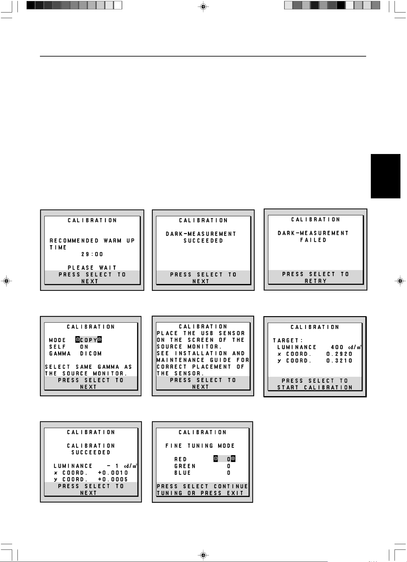
Before proper copy calibration can be
performed, displays should warm-up for a minimum 30 minutes. If the sensor is plugged in before the minute warm-up, a warning will
appear on-screen (Figure C.4). NOTE:
Stand-alone calibration can only be performed using the GretagMacbeth Eye-One Display
Sensor.
Refer to the KEY MAP (Figure A) when changing settings during the calibration.
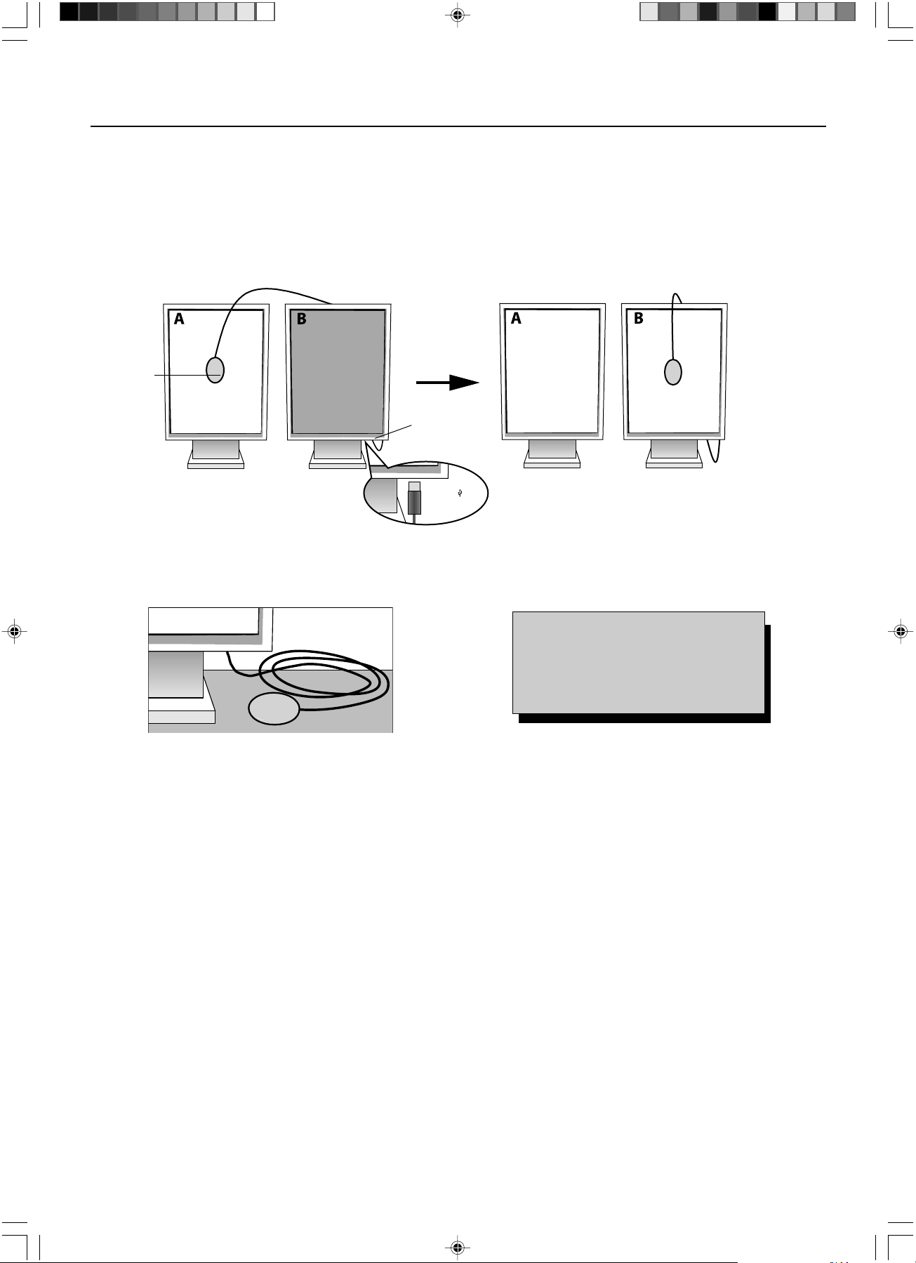
1. Plug-in the USB sensor to the sensor port (Figure C.1).
NOTE: Sensor port can only be used for the sensor connection.
2. The calibration menu will open automatically and the USB sensor will begin to initialize. After initializing, the DARK-
MEASUREMENT message is displayed. If the DARK-MEASUREMENT message is not displayed, please proceed to step 5.
3.
Place the USB sensor face down on a non-reflective, opaque surface (ie...desk or a mousepad) to measure the black
level (Figure C.3). Press “SELECT”.
4.
After the DARK-MEASUREMENT has succeeded (Figure C.5), press SELECT to continue. If dark-measurement fails (Figure C.6),
restart calibration procedure at Step 1.
5. Display A must display a white screen, enter the Advanced OSD by pressing RESET and EXIT. Use “<“ or “>” keys to
move into Tag 6 and select SELF-TEST MODE.
6.
Using “+” or “–”, select COPY in the MODE selection (Figure C.7). Select ON of OFF in the SELF selection. If ON selected,
SELF Calibration execute with COPY Calibration.
7. Select the target GAMMA: NO CORRECTION, DICOM, LOG LINEAR, PROGRAMMABLE and CUSTOM. Please
select the same target GAMMA as Display A.
NOTE: If CUSTOM is selected, the Gamma Value can be manually changed in intervals of 0.1 at 0.5-4.0.
8. The procedure will ask for the USB sensor to be placed on the center of the display panel (Figure C.8). Tilt the display
panel approximately 5˚ backward and place the USB sensor in the center of the display panel (Figure C.1).
NOTE: Place the USB sensor flat against the display to avoid external light contamination. DO NOT press the
calibrator against the display panel. Press “SELECT”.
White Point Matching/Copy Calibration
Display A – SOURCE display of white point to copy.
Display B – TARGET display which performs a copy calibration.
Figure C.1
Figure C.2
Sensor Port
Figure C.3 Figure A
KEY MAP
< / > : changes from setting to setting
– / + : changes the setting selection
(ie...SELF or COPY)
SELECT: moves to the next step of calibration
EXIT: moves back one step of calibration
USB
Sensor
USB icon ( ) is on
the other side
01_MD21GS3MPINSTALL_EN.P65 08/08/2005, 12:0012
English.13
English
White Point Matching/Copy Calibration –continued
9. Press SELECT on Display B to start reading the white point information of Display A.
10. After copying Display A information, the target LUMINANCE and target chromaticity coordinates will be stored and
displayed in the OSD of Display B. The TARGET VALUE is not adjustable (Figure C.9).
11. Remove
USB sensor
from source Display A and place in the center of Display B (Figure C.2).
12. Press SELECT to start the copy calibration. Copy calibration may take several minutes depending on user settings.
13. Once the calibration is successfully completed, the white points of Display A and Display B should match. After the
CALIBRATION SUCCEEDED message appears (Figure C.10), press SELECT to continue into the FINE TUNING MODE.
14. At the FINE TUNING MODE message (Figure C.11), press EXIT if the calibration is satisfactory. If the calibration is
unsatisfactory, there are two options:
(A) Manually fine tune the white point using the “+” and “–” keys.
(B) Restart the automatic copy calibration, press SELECT and return to Step 3.
15. To end the calibration mode, press “EXIT”.
Figure C.5 Figure C.6
Figure C.10 Figure C.11
Figure C.4
Figure C.8 Figure C.9Figure C.7
01_MD21GS3MPINSTALL_EN.P65 08/08/2005, 12:0013

English.14
Safety Precautions and Maintenance
FOR OPTIMUM PERFORMANCE, PLEASE NOTE THE FOLLOWING WHEN
SETTING UP AND USING THE NEC DISPLAY:
• DO NOT OPEN THE Display. There are no user serviceable parts inside and opening or removing covers may expose you to dangerous shock hazards
or other risks. Refer all servicing to qualified service personnel.
• Do not spill any liquids into the cabinet or use your display near water.
• Do not insert objects of any kind into the cabinet slots, as they may touch dangerous voltage points, which can be harmful or fatal or may cause electric
shock, fire or equipment failure.
• Do not place any heavy objects on the power cord. Damage to the cord may cause shock or fire.
• Do not place this product on an unbalanced or unstable cart, stand or table because the display may fall, causing serious damage.
• Do not place any objects onto the display and do not use the display outdoors.
•
The inside of the fluorescent tube located within the display contains mercury. Please follow the bylaws or rules of your municipality to dispose of the tube properly.
• Do not bend power cord.
• Do not use display in high temperatured, humid, dusty, or oily areas.
• Do not cover vent on display.
Immediately unplug your display from the wall outlet and refer servicing to qualified service personnel under the following conditions:
• When the power supply cord or plug is damaged.
• If liquid has been spilled, or objects have fallen into the display.
• If the display has been exposed to rain or water.
• If the display has been dropped or the cabinet damaged.
• If the display does not operate normally by following operating instructions.
• If glass is broken, handle with care.
• If display or glass is broken, do not come in contact with the liquid crystal and handle with care.
• Allow adequate ventilation around the display so that heat can properly dissipate. Do not block ventilated openings or place the display
near a radiator or other heat sources. Do not put anything on top of display.
• The power cable connector is the primary means of detaching the system from the power supply. The display should be installed close to a
power outlet which is easily accessible.
• Handle with care when transporting. Save packaging for transporting.
Image Persistence
Please be aware that LCD Technology may experience a phenomenon known as Image Persistence. Image Persistence occurs when a residual or “ghost”
image of a previous image remains visible on the screen. Unlike CRT monitors, LCD monitors’ image persistence is not permanent, but constant images being
displayed for a long period of time should be avoided. To alleviate image persistence, turn off the monitor for as long as the previous image was displayed.
For example, if an image was on the monitor for one hour and a residual image remains, the monitor should be turned off for one hour to erase the image.
NOTE: As with all personal display devices, we recommend displaying moving images and using a moving screen saver at regular intervals whenever the
screen is idle or turning off the display when not in use.
CORRECT PLACEMENT AND ADJUSTMENT OF THE DISPLAY CAN REDUCE EYE, SHOULDER
AND NECK FATIGUE. CHECK THE FOLLOWING WHEN YOU POSITION THE DISPLAY:
• For optimum results during self and copy calibrations, allow 30 minutes for warm-up.
• Adjust the display height so that the top of the screen is at or slightly below eye level. Your eyes should look slightly downward when viewing the middle
of the screen.
• Position your display no closer than 16 inches and no further away than 28 inches from your eyes. The optimal
distance is 20 inches.
• Rest your eyes periodically by focusing on an object at least 20 feet away. Blink often.
• Position the display at a 90° angle to windows and other light sources to minimize glare and reflections. Adjust the
display tilt so that ceiling lights do not reflect on your screen.
• Clean the display surface with a lint-free, non-abrasive cloth. Case of persistent dirt, wipe with cloth permeated
by water, ethanol, isopropyl-alcohol completely. Avoid using any cleaning solution or glass cleaner (ex Acid,
Alkali and Acetone).
• Adjust the display’s brightness control to enhance readability.
•
Position whatever you are looking at most of the time (the screen or reference material) directly in front of you to minimize
turning your head while you are typing.
•
Avoid displaying fixed patterns on the display for long periods of time to avoid image persistence (after-image effects).
Ergonomics
To obtain the best possible ergonomics benefits, we recommend the following:
• Use the preset Size and Position controls with standard signals
• Use non-interlaced signals with a vertical refresh rate of 60Hz
Cleaning the LCD Panel
• When the liquid crystal panel is stained with dust or dirt, please wipe with soft cloth gently.
• Please do not rub the LCD panel with hard material.
• Please do not apply pressure to the LCD surface.
• Please do not use OA cleaner it will cause deterioration or discolor on the LCD surface.
Cleaning the Cabinet
• Unplug the power supply
• Gently wipe the cabinet with a soft cloth
• To clean the cabinet, dampen the cloth with a neutral detergent and water, wipe the cabinet and follow with a dry cloth.
NOTE: Many plastics are used on the surface of the cabinet. DO NOT clean with benzene, thinner, alkaline detergent, alcoholic system detergent, glass
cleaner, wax, polish cleaner, soap powder, or insecticide. Do not touch rubber or vinyl to the cabinet for a long time. These types of fluids and fabrics
can cause the paint to deteriorate, crack or peel.
Recommended Use
CAUTION
01_MD21GS3MPINSTALL_EN.P65 08/08/2005, 12:0014
English.15
English
Specifications
Display Specifications MD21GS-3MP Display Notes
LCD Module Diagonal: 54 cm/21.3 inches Active matrix; thin film transistor (TFT) liquid
Viewable Image Size: 54 cm/21.3 inches crystal display (LCD); 0.2115mm dot pitch;
Native Resolution (Pixel Count): 1536 x 2048 (Portrait) 400 cd/m
2
calibrated white luminance;
2048 x 1536 (Landscape) 700:1 contrast ratio, typical.
Input Signal Video: Digital Input: DVI VideoDot Clock 162Mhz Max
Grayscale Tones 10 Bit: 1024 (10bit) shades of gray from
When used with an recommended
a pallet of 3061 (11.5bit)
10 bit
display card
8 Bit: 256 (8bit) shades of gray from a When used with an recommended
pallet of 3061 (11.5 bit) 8 bit display card
Synchronization Range Horizontal: 31.5 kHz to 96.0 kHz Automatically
Vertical: 30 Hz, 50 Hz to 85 Hz Automatically
Viewing Angle Left/Right: ±88° (CR > 10)
Up/Down: ±88° (CR > 10)
Image Formation Time 35 ms (Typ.)
Active Display Area Portrait: Horiz.: 325 mm/12.8 inches
Vert.: 433 mm/17.1 inches
Landscape: Horiz.: 433 mm/17.1 inches
Vert.: 325 mm/12.8 inches
Power Supply AC 100-240V ~ 50/60Hz
Current Rating 0.7 - 0.35 A
Dimensions Portrait: 358.7 mm (W) x 514 - 560 mm (H) x 200 mm (D)
14.1 inches (W) x 20.2 - 22.0 inches (H) x 7.9 inches (D)
Landscape: 467 mm (W) x 460 - 506 mm (H) x 200 mm (D)
18.4 inches (W) x 18.1 - 19.9 inches (H) x 7.9 inches (D)
Height Adjustment: 46 mm/1.8 inches
Weight 11.7 kg/25.8 lbs
Environmental Considerations
Operating Temperature: 5°C to 40°C/41°F to 104°F
Humidity: 30% to 80% (without condensation)
Feet: 0 to 10,000 Feet/0 to 3,048 m
Storage Temperature (in package): -20°C to 60°C/-4°F to 140°F
Humidity (in package): 10% to 85% (without condensation)
Feet (in package): 0 to 40,000 Feet/0 to 12,192 m
UL-Classification
According to the type of protection against electric shock: CLASS I
According to the degree of protection against electric shock: No Patient connection
According to the degree of protection against ingress of water as detailed in the current edition of IEC529: No Protection
According to the method of sterilization or disinfection recommended by the manufacturer: Not Specified
According to the degree of safety of application in the presence of a FLAMMABLE AN AESTHETIC MIXTURE WITH AIR or a WITH
OXYGEN OR NITROUS OXIDE: Not suitable
According to the mode of operation: Continuous operation
01_MD21GS3MPINSTALL_EN.P65 08/08/2005, 12:0015

English.16
DVI-D: The digital-only subset of DVI ratified by the Digital Display Working Group (DDWG) for digital connections between
computers and displays. As a digital-only connector, analog support is not provided off a DVI-D connector. As a DVI-based
digital only connection, only a simple adapter is necessary for compatibility between DVI-D and other DVI-based digital
connectors such as DFP and P&D.
P&D (Plug and Display): The VESA standard for digital flat panel display interfaces. It is more robust than DFP since it
allows for other options off a signal connector (options like USB, analog video and IEEE-1394-995). The VESA committee
has recognized that DFP is a subset of P&D. As a DVI-based connector (for the digital input pins), only a simple adapter is
necessary for compatibility between P&D and other DVI-based digital connector such as DVI and DFP.
Pivoting Stand: Allows users to adjust the display to the orientation that best fits their application, either Landscape orienta-
tion for wide documents, or portrait orientation for the ability to preview a full page on one screen at one time.
Reduced Footprint: Provides the ideal solution for environments requiring superior image quality but with size and weight
limitations. The display’s small footprint and low weight allow it to be moved or transported easily from one location to
another.
OSD (On-Screen-Display) Controls: advanced OSD controls allow you to quickly and easily adjust all elements of your
screen image via simple to use on-screen menus and includes a complete OSD Lock Out function.
ErgoDesign Features: Enhance human ergonomics to improve the working environment, protect the health of the user and
save money. Examples include
OSD controls for quick and easy image adjustments, tilt base for preferred angle of vision,
small footprint and compliance with MPRII guideline for lower emissions
.
Anti-glare and Low-reflection Screen: an anti-glare and low-reflection screen reduces glare and ambient reflection. The
BLACK level perception of the display is improved resulting in a clearer image.
Multiple Frequency Technology: Automatically adjusts display to the display card’s scanning frequency, thus displaying the
resolution required.
FullScan Capability: Allows you to use the entire screen area in most resolutions, significantly expanding image size.
Wide Viewing Angle Technology: Allows the user to be able to see the display from any angle (176 degrees) from any
orientation — Portrait or Landscape. Provides full 176° viewing angles either up, down, left or right.
VESA Standard Mounting Interface: Allows users to connect their display to any VESA standard third party mounting arm
or bracket. Allows for the display to be mounted on a wall or an arm using any third party compliant device.
X-Light Backlight System: Using an internal sensor, this allows for consistent brightness and white point levels over a long
period of time, providing the basis for excellent diagnostic quality. The system also allows for easy multiple display white
point matching with the use of a calibrator puck (sold separately), contributing to reduced costs and increased efficiency.
Features
01_MD21GS3MPINSTALL_EN.P65 08/08/2005, 12:0016
English.17
English
Troubleshooting
No picture
• The signal cable should be completely connected to the display card/computer.
• The display card should be completely seated in its slot.
• Check the power switch should be in the ON position.
• Computer power switch should be in the ON position.
• Check to make sure that a supported mode has been selected on the display card or system being used.
(Please consult display card or system manual to change graphics mode.)
• Check the display and your display card with respect to compatibility and recommended settings.
• Check the signal cable connector for bent or pushed-in pins.
Power Button does not respond
• Unplug the power cord of the display from the AC outlet to turn off and reset the display.
• Check the power switch on the top of the display (portrait) or side of the display (landscape).
Image Persistence
• Please be aware that LCD Technology may experience a phenomenon known as Image Persistence. Image Persistence occurs when
a residual or “ghost” image of a previous image remains visible on the screen. Unlike CRT monitors, LCD monitors’ image
persistence is not permanent, but constant images being displayed for a long period of time should be avoided. To alleviate image
persistence, turn off the monitor for as long as the previous image was displayed. For example, if an image was on the monitor for
one hour and a residual image remains, the monitor should be turned off for one hour to erase the image.
NOTE: As with all personal display devices, we recommend using a moving screen saver at regular intervals whenever the
screen is idle or turning off the display when not in use.
Message “OUT OF RANGE” is displayed (screen is either blank or shows rough images only)
• Image is roughly displayed (pixels are missing) and OSD warning “OUT OF RANGE” is displayed means the signal clock or
resolution is too high. Choose one of the supported modes.
• OSD warning “OUT OF RANGE” is displayed on a blank screen: Signal frequency is out of range. Choose one of the supported
modes.
Image is unstable, unfocused or swimming is apparent
• Signal cable should be completely attached to the computer.
• Check the display and your display card with respect to compatibility and recommended signal timings.
• If your text is garbled, change the video mode to non-interlace and use 60Hz refresh rate.
Display image is not sized properly
• Check to make sure that a supported mode has been selected on the display card or system being used.
(Please consult display card or system manual to change graphics mode.)
• Check the EXPANSION MODE in the OSD.
No Video
• If no video is present on the screen, turn the Power button off and on again.
• Make certain the computer is not in a power-saving mode (touch the keyboard or mouse).
No Tilt
• Rotate the screen to 90˚ clockwise until you hear one click.
• Refer to the Display Adjustment and Mounting section to insure correct installation of stand.
NO OSD
• Refer to the OSD LOCK OUT function in the Advanced OSD section of this manual.
01_MD21GS3MPINSTALL_EN.P65 08/08/2005, 12:0017

English.18
North America and Canada
NEC Monitor Customer Service & Support
Customer Service and Technical Support: (800) 632-4662
Fax: (801) 907-3805
Parts and Accessories/Macintosh
Cable Adapter: (800) 632-4662
Warranty Information: www.necdisplay.com
Online Technical Support www.necdisplay.com
Sales and Product Information
Sales Information Line: (888) 632-6487
Canadian Customers: (866) 771-0266, Ext#: 4037
Government Sales: (800) 284-6320
Government Sales email: gov@necdisplay.com
Electronic Channels
World Wide Web: www.necdisplay.com
Product Registration: www.necdisplay.com
Drivers and Downloads www.necdisplay.com
Europe
Address
NEC Display Solutions Europe GmbH Phone: +49(0)89 99699 - 0
Landshuter Allee 12 -14
D-80637 München
Electronic Channels
World Wide Web: www.medical.nec-display-solutions.com
References
01_MD21GS3MPINSTALL_EN.P65 08/08/2005, 12:0018
English.19
English
DECLARATION OF CONFORMITY
For USA
This device complies with Part 15 of FCC Rules. Operation is subject to the following two conditions. (1) This device may not cause harmful
interference, and (2) this device must accept any interference received, including interference that may cause undesired operation.
Type of Product: Display Monitor
Equipment Classification: Class B Peripheral
Model:
MD21GS-3MP-CB/MD21GS-3MP-BB
We hereby declare that the equipment specified above
conforms to the technical standards as specified in the FCC Rules.
FCC Information
1.Use the attached specified cables with the MD21GS-3MP grayscale display so as not to interfere with radio and television reception.
(A) Please use the supplied power cord or equivalent to ensure FCC compliance.
(B) Please use the supplied shielded video signal cable.
Use of other cables and adapters may cause interference with radio and television reception.
2.This equipment has been tested and found to comply with the limits for a Class B digital device, pursuant to part 15 of the FCC Rules.
These limits are designed to provide reasonable protection against harmful interference in a residential installation. This equipment
generates, uses, and can radiate radio frequency energy, and, if not installed and used in accordance with the instructions, may cause
harmful interference to radio communications. However, there is no guarantee that interference will not occur in a particular installation.
If this equipment does cause harmful interference to radio or television reception, which can be determined by turning the equipment off
and on, the user is encouraged to try to correct the interference by one or more of the following measures:
• Reorient or relocate the receiving antenna.
• Increase the separation between the equipment and receiver.
• Connect the equipment into an outlet on a circuit different from that to which the receiver is connected.
• Consult your dealer or an experienced radio/TV technician for help.
If necessary, the user should contact the dealer or an experienced radio/television technician for additional suggestions. The user may find the
following booklet, prepared by the Federal Communications Commission, helpful: ”How to Identify and Resolve Radio-TV Interference
Problems.“ This booklet is available from the U.S. Government Printing Office, Washington, D.C., 20402, Stock No. 004-000-00345-4.
For Europe
Means of Conformity
Device Classification: Class I, non-measuring function
Applicable Rules: Annex IX, Rules 1.4 (Section 1) and 1.1 (Section 3)
Product Name: NEC MD21GS-3MP
21.3” Diagnostic Imaging Grayscale LCD Monitor
Model Numbers: MD21GS-3MP-BK-BB (Blue Base)
MD21GS-3MP-BK-CB (Clear Base)
UMDNS Code: 16-603
NEC Display Solutions Europe GmbH declares that the products listed are in conformity with the essential requirements and provisions
of the Council Directive 93/42/EEC and conform to the applicable clauses of the following standards:
– EN 60601-1
– EN 60601-1-2
– EN 61000-3-2
– EN 61000-3-3
NEC Display Solutions Europe GmbH
Landshuter Allee 12-14. 80637 München, Germany
For Canada
Canadian Department of Communications Compliance Statement
DOC: This Class B digital apparatus meets all requirements of the Canadian Interference-Causing Equipment Regulations.
C-UL: Bears the C-UL Mark and is in compliance with Canadian Safety Regulations according to CAN/CSA C22.2 No. 601.1.
U.S. Responsible Party: NEC Display Solutions of America, Inc.
Address: 500 Park Blvd, Suite 1100
Itasca, Illinois 60143
Tel. No.: (630) 467-3000
01_MD21GS3MPINSTALL_EN.P65 08/08/2005, 12:0019

English.20
01_MD21GS3MPINSTALL_EN.P65 08/08/2005, 12:0020
Deutsch.1
Deutsch
Wichtige Informationen zum Netzkabel
VORSICHT: Bitte verwenden Sie das mit diesem Monitor gelieferte Netzkabel gemäß der folgenden Tabelle. Setzen Sie sich mit Ihrem
Händler in Verbindung, wenn der Monitor ohne Netzkabel geliefert wurde. In allen anderen Fällen ist ein für die Netzspannung
geeignetes und zugelassenes Netzkabel zu verwenden, dass den Sicherheitsstandards des betreffenden Landes entspricht.
Wenn Sie diesen Monitor in Nordamerika einsetzen, verwenden Sie bitte ein Netzkabel der Spezifikation North America Hospital Grade.
Einsatzempfehlungen
Der Graustufenmonitor MD21GS-3MP ist für die Anzeige und Betrachtung digitaler Bilder zur Diagnose durch einen ausgebildeten Arzt
vorgesehen. Um eine der Spezifikation gemäße Leistung zu erzielen, betreiben Sie den Monitor bitte nur mit von NEC empfohlenen Grafikkarten.
Für europäische Kunden
Dieser Monitor darf nur von autorisiertem und speziell ausgebildeten Personal ausgepackt, installiert und kalibriert
werden. Jede Installation durch nicht autorisierte Personen geschieht auf eigene Gefahr. Wir übernehmen keine
Verantwortung für eventuelle Fehlfunktion des Geräts.
Medizinische Bilddarstellung
Der NEC MD21GS-3MP ist für die Darstellung medizinischer Graustufenbilder von 3 Megapixeln (1536 x 2048) bestimmt.
Dieser Monitor ist auf eine dem Standard DICOM Part 14 entsprechende Gammakorrektureinstellung abgestimmt.
Alle Marken, Namen und Produkte sind Marken oder eingetragene Marken der jeweiligen Eigentümer.
WARNUNG
SETZEN SIE DAS GERÄT WEDER REGEN NOCH FEUCHTIGKEIT AUS, DA ES ANDERNFALLS ZU FEUER ODER STROMSCHLÄGEN KOMMEN KANN.
VERWENDEN SIE DEN NETZSTECKER DIESES GERÄTS KEINESFALLS MIT EINEM VERLÄNGERUNGSKABEL ODER EINER STECKDOSENLEISTE, WENN DIE
STECKERSTIFTE NICHT VOLLSTÄNDIG EINGEFÜHRT WERDEN KÖNNEN.
ÖFFNEN SIE DAS GEHÄUSE NICHT, DA SICH IM INNEREN KOMPONENTEN BEFINDEN, DIE UNTER HOCHSPANNUNG STEHEN. LASSEN SIE
WARTUNGSARBEITEN VON QUALIFIZIERTEN WARTUNGSTECHNIKERN DURCHFÜHREN.
ZIEHEN SIE DAS NETZKABEL AUS DER STECKDOSE, UM STROMSCHLÄGE ZU VERHINDERN. ERST NACH DEM TRENNEN DES GERÄTS
VOM STROMNETZ IST GEWÄHRLEISTET, DASS AN KEINER GERÄTEKOMPONENTE SPANNUNG ANLIEGT. ENTFERNEN SIE KEINESFALLS
DIE GEHÄUSEABDECKUNG (GEHÄUSERÜCKSEITE). IM INNEREN BEFINDEN SICH KEINE VOM BENUTZER ZU WARTENDEN
KOMPONENTEN. LASSEN SIE WARTUNGSARBEITEN VON QUALIFIZIERTEN WARTUNGSTECHNIKERN DURCHFÜHREN.
Dieses Symbol weist den Benutzer auf nicht isolierte spannungsführende Komponenten im Gerät hin, die Stromschläge verursachen können.
Aus diesem Grund dürfen Sie keinesfalls Kontakt mit einer Komponente im Geräteinneren herstellen.
Dieses Symbol weist den Benutzer auf wichtige Informationen zu Betrieb und Pflege dieses Geräts hin. Die Informationen sollten sorgfältig
gelesen werden, um Probleme zu vermeiden.
VORSICHT
VORSICHT:
Steckertyp
Europäisch
(Kontinent)
Chinesisch
North America
Hospital Grade
Japanisch
(nur für den japanischen Markt)
Steckerform
Land
Spannung
120 230 220 100
USA/Kanada EU (außer GB) China Japan
(grüner Punkt
und Aufkleber)
02_MD21GS3MPINSTALL_DE.P65 08/08/2005, 12:001

Deutsch.2
Der Karton* mit Ihrem neuen NEC LCD-Monitor sollte folgende Komponenten enthalten:
• Monitor MD21GS-3MP mit neig-, schwenk- und höhenverstellbarem Pivotfuß
• Netzkabel
• Kurzübersicht
• Installations- und Wartungshandbuch
• Signalkabel (Kabel von DVI-D auf DVI-D)
• Ferritkern
*2
• CD-ROM
Vollständige Informationen zur Grafikkarte entnehmen Sie bitte der Installationsanleitung der Grafikkarte.
Informationen zur Software GammaComp MD entnehmen Sie bitte dem Benutzerhandbuch zu GammaComp MD.
* Bewahren Sie den Originalkarton und das Verpackungsmaterial für spätere Transporte des Monitors auf.
*2
Für Netzkabel (Kontinentaleuropa und China)
Inhalt der Verpackung
Öffnen Sie den Ferritkern und
klemmen Sie ihn an das Netzkabel.
Schließen Sie den
Ferritkern.
Bringen Sie den Ferritkern am Ende des Netzkabels an.
Nur AC-IN-Seite des Monitors.
Ferritkern
Ferritkern
Netzkabel
Signalkabel
Kurzübersicht
Installations- und
Wartungshandbuch
Ferritkern
CD-ROM
02_MD21GS3MPINSTALL_DE.P65 08/08/2005, 12:002
Deutsch.3
Deutsch
Grafikkarteninstallation
1.
Öffnen Sie den Computer entsprechend den Anleitungen des Herstellers, um Zugang zu einem PCI-, AGP- oder PCI-E-Steckplatz zu erhalten.
2. Setzen Sie die Grafikkarte in einen freien PCI-Steckplatz ein und ziehen Sie alle Schrauben fest.
3. Bringen Sie die Abdeckung des Computers wieder an.
HINWEIS: Informationen zur Treiberinstallation, zu den Anzeigemodi im Multimonitormodus und zur Einstellung der Dip-Schalter
entnehmen Sie bitte der Dokumentation des Grafikkartenherstellers.
Anschluss des LCD-Monitors an einen PC
Nach erfolgreicher Installation der Grafikkarte, schließen Sie den Monitor entsprechend den folgenden Anleitungen an den PC an:
1. Fahren Sie den Computer herunter und schalten Sie ihn aus.
2. Verbinden Sie das DVI-D-Kabel mit dem Anschluss der Grafikkarte in Ihrem System (Abbildung A.1).
HINWEIS: Wenn Sie zwei Monitore anschließen, verbinden Sie ein DVI-D-Kabel mit den Anschlüssen 1 und 2 der Grafikkarte
(Abbildung A.1). Weitere Informationen zur Grafikkarteninstallation finden Sie im Handbuch zur Grafikkarte.
Ziehen Sie die Schrauben fest.
3. Zum Entfernen der Kabelabdeckung lösen Sie die Verriegelungen, indem Sie darauf drücken. Heben Sie dann die Abdeckung an
(Abbildung B.1).
4. Verbinden Sie das DVI-D-Kabel mit dem Anschluss auf der Rückseite des Monitors (Abbildung C.1).
HINWEIS: Eine fehlerhafte Kabelverbindung kann zu Betriebsfehlern, Beschädigungen von Komponenten des LCD-Moduls und einer
Verkürzung der Lebensdauer dieses Moduls führen.
5. Stecken Sie ein Ende des Netzkabels auf der Rückseite des Monitors und das andere Ende in die Steckdose ein (Abbildung C.1).
Bringen Sie die Kabelabdeckung wieder an.
HINWEIS: Informationen zur Neigung, Höheneinstellung und Drehung des Monitors beim Anbringen der Signal- und Netzkabel
finden Sie im Abschnitt Einstellung und Montage des Monitors.
HINWEIS:
Beachten Sie zur Auswahl des richtigen Netzkabels den entsprechenden Sicherheitshinweis in dieser Bedienungsanleitung.
6. Befestigen Sie die Signal- und Netzkabel unter dem Kabelclip (Abbildung B.1).
HINWEIS: Lösen Sie die Kabel aus dem Clip, bevor Sie die Kabelabdeckung entfernen.
7. Schalten Sie den Monitor mit dem Netzschalter auf der oberen (Hochformat) oder linken (Querformat) Seite ein (Abbildung D.1).
Schalten Sie den Computer ein.
HINWEIS: Drücken Sie den Schalter NICHT mehrmals.
8. Im Abschnitt OSD dieser Bedienungsanleitung finden Sie eine ausführliche Beschreibung der OSD Bedienelemente.
HINWEIS: Treten Probleme auf, beachten Sie bitte den Abschnitt Fehlerbehebung.
HINWEIS: Externe Hardware, die mit dem Signaleingang, Signalausgang oder einem anderen Anschluss verbunden wird, muss den
jeweiligen IEC-Standards entsprechen.
Kurzanleitung
Abbildung C.1
Abbildung A.1
Anschluss 2 für Zweitmonitor
Abbildung B.1
Abbildung D.1
Clip
02_MD21GS3MPINSTALL_DE.P65 08/08/2005, 12:003
Deutsch.4
Einstellung und Montage des Monitors
Heben und Senken des Bildschirms
Der Monitor kann im Hoch- und im Querformat gehoben oder gesenkt
werden. Fassen Sie den Monitor zu diesem Zweck auf beiden Seiten an,
und heben oder senken Sie ihn auf die gewünschte Höhe.
HINWEIS: Heben und senken Sie den Monitor vorsichtig, und achten
Sie darauf, dass Sie Ihre Finger nicht einklemmen.
Bildschirmdrehung
Vor dem Drehen muss der Bildschirm in die höchste Position gehoben werden,
damit er nicht gegen den Ständer stößt und Sie sich die Finger nicht
einklemmen. Sie können den Bildschirm nun drehen, indem Sie den Monitor
mit beiden Händen an den Seiten fassen und im Uhrzeigersinn aus dem
Quer- in das Hochformat bzw. gegen den Uhrzeigersinn aus dem Hoch- in
das Querformat drehen. Informationen dazu, wie Sie die Darstellung des
OSD Menüs zwischen Hoch- und Querformat umschalten, finden Sie in der
Beschreibung der Funktion „OSD Darstellung“ im Abschnitt Bedienelemente.
Neigen und Schwenken
Fassen Sie den Monitor an beiden Seiten und neigen bzw. drehen Sie ihn
nach Bedarf. HINWEIS: Neigen Sie den Monitor vorsichtig.
Montage eines alternativen VESA LCD-Monitors
1. Ziehen Sie alle Kabel ab.
2. Fassen Sie den Monitor auf beiden Seiten an, und heben Sie ihn in die höchste
Position. Drehen Sie den Monitor um 90° im Uhrzeigersinn in die
Querformatposition.
3. Legen Sie den Monitor mit der Vorderseite nach unten in Querformatposition
auf eine weiche Oberfläche. Der Bildschirm sollte auf eine um mindestens 29 mm
erhöhte Fläche gelegt werden, damit der Fuß bündig mit der Oberfläche des
Tisches abschließt. (Abbildung S.1).
4. Entfernen Sie die beiden oberen Schrauben, mit denen der Fuß am Monitor
befestigt ist (Abbildung S.2). Drehen Sie den Fuß um 180° gegen den
Uhrzeigersinn (es klickt zweimal). Entfernen Sie die beiden unteren Schrauben (Abbildung S.3), und heben Sie den Fuß ab.
Der Monitor kann jetzt auf andere Art montiert werden.
5. Führen Sie die Schritte in umgekehrter Reihenfolge aus, um den Fuß wieder anzubringen: Ziehen Sie die beiden unteren Schrauben
fest, drehen Sie den Fuß um 180° im dem Uhrzeigersinn (es klickt zweimal), und ziehen Sie die beiden oberen Schrauben fest.
HINWEIS: Verwenden Sie ausschließlich VESA-kompatible Montagemethoden (100 mm Abstand).
HINWEIS: Entfernen Sie den Monitorfuß vorsichtig.
HINWEIS: Wenn Sie das LCD in die Querformatposition schwenken, achten Sie darauf, dass sich die beiden runden Einkerbungen
auf der Unterseite des Bildschirms befinden (Abbildung S.4).
VORSICHT: Verwenden Sie die Originalschrauben (4 Stück) für die Montage, um Beschädigungen an Monitor und Fuß zu
vermeiden. Die Sicherheitsvorschriften verlangen, dass der Monitor an einem Tragarm montiert wird, der für das
Gewicht des Monitors ausreichend stabil ist. Der LCD-Monitor darf nur auf einem zugelassenen Arm montiert werden,
der beispielsweise mit einem GS-Zeichen versehen ist.
Abbildung S.4Abbildung S.3Abbildung S.2
Abbildung S.1
29 mm
02_MD21GS3MPINSTALL_DE.P65 08/08/2005, 12:004
Deutsch.5
Deutsch
Einstellungen
Die OSD Bedienelemente (On-Screen Display) befinden sich auf der Rückseite des Monitors. Sie können auf das OSD
Menü zugreifen, indem Sie eine der Steuerungstasten (<, >, –, +) drücken.
1. LED Zeigt die Spannungsversorgung und den Signalzustand an. Die LED kann ein- und ausgeschaltet
oder abgeblendet werden. Weitere Informationen finden Sie im Abschnitt Erweiterte OSD
Einstellungen unter „Helligkeit der LED“.
Grün – Signal ist vorhanden und Stromzufuhr eingeschaltet
Orange – Kein Signal
2. RESET Setzt das markierte Steuerungsmenü auf die Werkseinstellungen zurück.
3. SELECT Öffnet das OSD Steuerungsmenü und das OSD Untermenü.
4/5. ADJUST -/+ Verschiebt die Markierung nach links oder rechts, um den Wert zu erhöhen bzw. verringern.
6/7. CONTROL </> Verschiebt die Markierung nach links oder rechts, um die Menüs auszuwählen.
Verschiebt die Markierung nach oben oder unten, um eine der Steuerungen auszuwählen.
8. EXIT Schließt das OSD Steuerungsmenü und Hauptmenü.
9. Sensoranschluss Für optionalen externen Sensor für die Selbstkalibrierung und das Kopieren der Kalibrierung.
10. Tastenbeschreibung Die Tastenbeschreibung wird automatisch auf dem Bildschirm angezeigt, wenn Sie eines der
Bedienelemente auf der Rückseite betätigen. Die Ausrichtung der Tastenbeschreibung wird
zusammen mit der des OSD Menüs geändert.
HINWEIS: Wenn Sie RESET im Haupt- oder im Untermenü drücken, wird ein Fenster mit einer Warnung angezeigt, in dem
Sie die Funktion RESET mit der Taste EXIT abbrechen können.
Hochformatmodus
Querformatmodus
02_MD21GS3MPINSTALL_DE.P65 08/08/2005, 12:005
Deutsch.6
On-Screen Display
Helligkeit
HELLIGKEIT: Passt die Bild- und Hintergrundhelligkeit des Bildschirms an. Wenn die HELLIGKEIT angepasst wird,
blinkt der numerische Wert.
Bildposition (außer im Packed Pixel-Modus/10 Bit)
LINKS/RECHTS: Steuert die horizontale Bildposition im Anzeigebereich des LCD.
AUF/AB: Steuert die vertikale Bildposition im Anzeigebereich des LCD.
Weißpunktauswahl
STANDARD: Werksseitige Voreinstellung der Weißpunktauswahl (je nach Modell „Clear Base“ oder „Blue Base“)..
WEISSKOPIE: Der Weißpunkt wurde mithilfe der kopierten Kalibrierung eingestellt.
ORIGINALFARBEN: Voreingestellter Weißpunkt des Monitors. Die maximale Helligkeitseinstellung ist verfügbar.
Hilfsfunktionen 1
SCHÄRFE: Diese Funktion passt den Monitor digital an, um scharfe Bilder zu erhalten. Wenn die werksseitigen
Einstellungen nicht ausreichend sind, kann das Bild manuell angepasst werden. Diese Funktion ist verfügbar, wenn
GRAUSTUFEN-BIT auf 8 Bit eingestellt ist.
EXPANSIONSMODUS: Festlegung der Zoom-Methode.
VOLLBILD: Die Bilddarstellung wird unabhängig von der Auflösung auf 1536 x 2048 Pixel erweitert.
SEITENVERHÄLTNIS: Das Bild wird vergrößert, ohne das Seitenverhältnis zu ändern.
AUS: Die Bilddarstellung wird nicht erweitert.
ANWENDER (nur bei Auflösung von 1536 x 2048 Pixel): Zoom mit fixiertem Zentrum. Wählen Sie einen von
neun Expansionsmodi. In diesem Modus ist die Auflösung gegebenenfalls gering und der Bildschirm enthält leere
Bereiche. Dieser Modus wurde für spezielle Grafikkarten entwickelt.
GRAUSTUFEN-BIT: Wählen Sie die Anzahl der GRAUSTUFEN-BITS der Grafikkarte aus.
8 bit – 256 Graustufen
10 bit – 1024 Graustufen
Hilfsfunktionen 2
SPRACHE: Die OSD Menüs sind in sieben Sprachen verfügbar.
OSD LINKS/RECHTS: Sie können festlegen, wo das OSD Steuerungsfenster auf dem Bildschirm angezeigt werden
soll. Die Position kann nach links oder rechts verschoben werden.
OSD AUF/AB: Sie können festlegen, wo das OSD Steuerungsfenster auf dem Bildschirm angezeigt werden soll.
Die Position kann nach oben oder unten verschoben werden.
OSD ANZEIGEDAUER: Das OSD Steuerungsmenü wird ausgeblendet, wenn es nicht mehr verwendet wird. Im
Untermenü „OSD Anzeigedauer“ können Sie festlegen, nach welchem Zeitraum das OSD Steuerungsmenü
ausgeblendet wird, wenn der Benutzer keine Taste drückt. Die Voreinstellungen reichen von 10 -120 Sekunden in
5-Sekunden-Abständen.
OSD ABSCHALTUNG: Diese Funktion sperrt den Zugriff auf einige oder alle Funktionen der OSD Steuerung.
Wenn Sie im Modus „OSD Abschaltung“ auf die OSD Steuerungen zugreifen, wird ein Bildschirm angezeigt, der
auf die Sperre der OSD Steuerungen hinweist. Es gibt drei Arten der OSD Abschaltung:
OSD ABSCHALTUNG ohne Steuerung: Um die Funktion „OSD Abschaltung“ zu aktivieren, halten Sie die Tasten
SELECT und > gleichzeitig gedrückt. Um die Funktion „OSD Abschaltung“ zu deaktivieren, halten Sie die Tasten
SELECT und > gleichzeitig gedrückt, während Sie sich im OSD Menü befinden. Im Modus „OSD Abschaltung“
können keine Steuerungen angepasst werden.
GRAY
BIT
MODUS Tastenkombination zur Aktivierung HELLIGKEIT ABSCHALT-Warnung
OSD ABSCHALTUNG SELECT, > Nein Ja
ohne Steuerung
OSD ABSCHALTUNG SELECT, – , < Ja Ja
mit HELLIGKEIT
Informationen zur Option BENUTZERDEFINIERTE ABSCHALTUNG finden Sie im Abschnitt „Erweiterte OSD Einstellungen“.
02_MD21GS3MPINSTALL_DE.P65 08/08/2005, 12:006

Deutsch.7
Deutsch
On-Screen Display – Fortsetzung
OSD ABSCHALTUNG mit Taste HELLIGKEIT: Um die Funktion „OSD Abschaltung“ zu aktivieren, drücken Sie die
Taste SELECT, und halten Sie die Tasten – und > gleichzeitig gedrückt. Um die Funktion „OSD Abschaltung“ zu
deaktivieren, drücken Sie die Taste SELECT, und halten Sie die Tasten – und > gleichzeitig gedrückt, während
Sie sich im OSD Menü befinden. Im Modus „OSD Abschaltung“ kann die Helligkeit angepasst werden.
OSD ROTATION: Mit dieser Funktion schalten Sie die Darstellung des OSD Menüs zwischen Hoch- und
Querformat um. Verwenden Sie die Tasten + oder –, um die Ausrichtung des OSD Menüs und der
Tastenbeschreibung zu ändern.
AUFLÖSUNGSANZEIGE: Die optimale Auflösung beträgt 1536 x 2048 Pixel. Wenn Sie EIN wählen, wird in
einer Bildschirmmeldung nach 30 Sekunden darauf hingewiesen, dass nicht die Auflösung 1536 x 2048 Pixel
verwendet wird.
DIREKTZUGRIFF: Sie können die Helligkeit direkt einstellen. Wenn diese Funktion aktiviert ist, können Sie die
Helligkeit mit den Tasten <, >, + oder – einstellen, während das OSD Menü deaktiviert ist. Über die Taste EXIT
können Sie auf das Standard-OSD Menü zugreifen.
WERKSEINSTELLUNG: Mit dieser Funktion werden alle OSD Einstellungen (HELLIGKEIT, BILDPOSITION,
WEISSPUNKTAUSWAHL, SCHÄRFE, EXPANSIONSMODUS, ABSCHALT-TIMER, OSD LINKS/RECHTS, OSD
AUF/AB, OSD ANZEIGEDAUER, GRAFIKMODUS) auf die Werkseinstellungen zurückgesetzt. Einzelne
Einstellungen können durch Markieren der betreffenden Steuerung und anschließendes Drücken der Taste RESET
zurückgesetzt werden.
Information
GRAFIKMODUS: Stellt Informationen zur aktuellen Auflösung sowie technische Daten wie verwendetes
Signaltiming, horizontale und vertikale Frequenz bereit.
MONITORINFORMATION: Die Modell- und die Seriennummer des Monitors.
OSD Warnungen
Um eine OSD Warnung vom Bildschirm zu entfernen, drücken Sie die Taste EXIT.
KEIN SIGNAL: Diese Funktion gibt eine Warnung aus, wenn kein horizontales oder vertikales Sync-Signal
verfügbar ist. Das Fenster Kein Signal wird nach dem Einschalten oder einem Wechsel des Eingangssignals
angezeigt.
AUFLÖSUNGSANZEIGE: Diese Funktion warnt Sie, wenn nicht die optimale Auflösung verwendet wird. Nach
dem Einschalten, nach einer Änderung des Videosignals oder wenn das Videosignal nicht die richtige Auflösung
besitzt, wird das Fenster Auflösungsanzeige angezeigt. Diese Funktion kann im Menü HILFSFUNKTIONEN 2
deaktiviert werden.
FREQUENZ ZU HOCH: Diese Funktion empfiehlt die optimale Auflösung und Bildwiederholrate. Nach dem
Einschalten, nach einer Änderung des Eingangssignals oder wenn das Videosignal nicht die richtige Auflösung
besitzt, wird das Fenster Frequenz zu hoch angezeigt.
OSD ABSCHALTUNG: Diese Funktion zeigt an, dass die OSD Funktionen vom Benutzer gesperrt wurden. Diese
Funktion kann im Menü BENUTZERDEFINIERTE ABSCHALTUNG deaktiviert werden.
LEBENSDAUER DER LAMPE: Diese OSD Warnung wird angezeigt, wenn die Lebensdauer der Lampe 1000/
500/0 Stunden beträgt. Der Bildschirm kann den vom Benutzer eingestellten Luminiszenzgrad nicht beibehalten,
die Weißpunkteinstellung bleibt jedoch bestehen. Bitte wenden Sie sich an Ihren Händler, wenn diese OSD
Warnung angezeigt wird.
HELLIGKEITSWARNUNG: Diese Funktion zeigt an, dass die Einstellung der HELLIGKEIT nicht abgeschlossen
werden kann.
02_MD21GS3MPINSTALL_DE.P65 08/08/2005, 12:007
Deutsch.8
Erweiterte OSD Einstellungen
Die erweiterten OSD Einstellungen bieten gegenüber den OSD Standardfunktionen weitergehende Steuerungsmöglichkeiten. Wenn die
OSD Funktionen abgeschaltet sind, drücken Sie die Tasten RESET und EXIT gleichzeitig, um die erweiterten OSD Einstellungen zu
aktivieren. HINWEIS: Dieses Menü ist größer als das normale OSD Menü. Um eine Einstellung vorzunehmen, markieren Sie den
entsprechenden Menüpunkt und drücken SELECT. Zur Auswahl eines anderen Menüpunkts drücken Sie EXIT und anschließend < oder >,
um den gewünschten Menüpunkt zu markieren.
Menüpunkt1
Brightness Passt die Bild- und Hintergrundhelligkeit des Bildschirms unter Verwendung des numerischen Wertes an. Drücken Sie
+ oder –, um die Einstellung anzupassen. Wenn die HELLIGKEIT angepasst wird, blinkt der numerische Wert.
Menüpunkt2
Dieser Menüpunkt kann nicht angepasst werden.
Menüpunkt3
H. Position Steuert die horizontale Bildposition im Anzeigebereich des LCD. Drücken Sie + oder –, um die Einstellung anzupassen.
V. Position Steuert die vertikale Bildposition im Anzeigebereich des LCD. Drücken Sie + oder –, um die Einstellung anzupassen.
Menüpunkt4
Gamma Selection Ermöglicht Ihnen, die Helligkeit der Graustufen manuell einzustellen. Es gibt fünf Optionen:
NO CORRECTION, DICOM, LOG LINEAR, CUSTOM und PROGRAMMABLE.
1. NO CORRECTION
2. DICOM: DICOM GSDF (Grayscale Standard Display Function) ist möglich. DICOM LUT wird berechnet auf der
Basis der werksseitigen Kalibrierungsdaten für jeden einzelnen Monitor.
3. LOG LINEAR: Luminiszenzänderungen werden rhythmisch erfasst in Reaktion auf lineare Helligkeitsunterschiede.
4. CUSTOM: Der Gammawert kann im Bereich von 0.5 bis 4.0 in Schritten von 0.1 ausgewählt werden.
5. PROGRAMMABLE: Die Graustufenhelligkeit kann mithilfe der Software GammaComp MD geändert werden.
Gamma Offset Passt den Schwarzwert der Gamma-Einstellung an. HINWEIS: DICOM kann nicht angepasst werden.
Menüpunkt5
White Point Selection DEFAULT: Werksseitige Voreinstellung der Weißpunktauswahl (je nach Modell „Clear Base“ oder „Blue Base“)..
COPIED WHITE: Der Weißpunkt wurde mithilfe der kopierten Kalibrierung eingestellt.
NATIVE: Voreingestellter Weißpunkt des Monitors. Die maximale Helligkeitseinstellung ist verfügbar.
Menüpunkt6
Self Test Mode Zeigt einen komplett weißen Bildschirm an. Wird für die Weißpunktabgleich/kopierte Kalibrierung verwendet.
Lamp Lifetime Zeit die geschätzte Lebensdauer der Lampe an. Die Lebensdauer ist abhängig von der Luminiszenzkalibrierung.
Temperature Zeigt die Temperatur im Monitor und die Temperatur des internen Sensors für die Hintergrundbeleuchtung an.
BRIGHTNESS Zeigt die Zieleinstellung und die aktuelle Einstellung für den Luminiszenzgrad in cd/m
2
an.
INFO
Menüpunkt7
Sharpness Diese Funktion passt den Monitor digital an, um scharfe Bilder zu erhalten. Wenn die werksseitigen Einstellungen
nicht ausreichend sind, kann das Bild manuell angepasst werden. Diese Funktion ist verfügbar, wenn GRAUSTUFEN-
BIT auf 8 Bit eingestellt ist.
Expansion Mode Festlegung der Zoom-Methode.
FULL: Die Bilddarstellung wird unabhängig von der Auflösung auf 1536 x 2048 Pixel erweitert.
ASPECT: Das Bild wird vergrößert, ohne das Seitenverhältnis zu ändern.
OFF: Die Bilddarstellung wird nicht erweitert.
CUSTOM (nur 1536 x 2048): Zoom mit fixiertem Zentrum. Wählen Sie einen von neun Expansionsmodi. In diesem
Modus ist die Auflösung gegebenenfalls gering und der Bildschirm enthält leere Bereiche. Dieser Modus wurde für
spezielle Grafikkarten entwickelt.
Grayscale Bit Wählen Sie die Anzahl der GRAUSTUFEN-BITS (8 oder 10) aus.
Language Die OSD Menüs sind in sieben Sprachen verfügbar. Drücken Sie + oder –, um die Einstellung auszuwählen.
OSD Left/Right Sie können festlegen, wo das OSD Steuerungsfenster auf dem Bildschirm angezeigt werden soll.
Die Position kann manuell nach links oder rechts verschoben werden.
OSD Down/UP Sie können festlegen, wo das OSD Steuerungsfenster auf dem Bildschirm angezeigt werden soll.
Die Position kann manuell nach oben oder unten verschoben werden.
OSD Turn Off Das OSD Steuerungsmenü wird ausgeblendet, wenn es nicht mehr verwendet wird. Im Untermenü „OSD
Anzeigedauer“ können Sie festlegen, nach welchem Zeitraum das OSD Steuerungsmenü ausgeblendet wird, wenn
der Benutzer keine Taste drückt. Die Voreinstellungen reichen von 10 -120 Sekunden in 5-Sekunden-Abständen.
02_MD21GS3MPINSTALL_DE.P65 08/08/2005, 12:008
Deutsch.9
Deutsch
Erweiterte OSD Einstellungen – Fortsetzung
OSD Lock Out Diese Funktion sperrt den Zugriff auf alle Funktionen der OSD Steuerungen. Wenn Sie im Modus „OSD
Abschaltung“ auf die OSD Steuerungen zugreifen, wird ein Bildschirm angezeigt, der auf die Sperre der OSD
Steuerungen hinweist. Es gibt drei Arten der OSD Abschaltung:
OSD ABSCHALTUNG ohne Steuerung: Um die Funktion „OSD Abschaltung“ zu aktivieren, halten Sie die Tasten
SELECT und > gleichzeitig gedrückt. Um die Funktion „OSD Abschaltung“ zu deaktivieren, halten Sie die Tasten
SELECT und > gleichzeitig gedrückt, während Sie sich im OSD Menü befinden. Im Modus „OSD Abschaltung“
können keine Steuerungen angepasst werden.
OSD ABSCHALTUNG mit Taste HELLIGKEIT: Um die Funktion „OSD Abschaltung“ zu aktivieren, drücken Sie die
Taste SELECT, und halten Sie die Tasten – und > gleichzeitig gedrückt. Um die Funktion „OSD Abschaltung“ zu
deaktivieren, drücken Sie die Taste SELECT, und halten Sie die Tasten – und > gleichzeitig gedrückt, während Sie
sich im OSD Menü befinden. Im Modus „OSD Abschaltung“ kann die Helligkeit angepasst werden.
BENUTZERDEFINIERT: Drücken Sie RESET und EXIT, um das Menü BENUTZERDEFINIERT zu öffnen. Wählen Sie
FREIGEGEBEN oder GESPERRT für HELLIGKEIT oder WARNUNG (AUFLÖSUNGSANZEIGE/OSD ABSCHALTUNG).
OSD Rotation Mit dieser Funktion schalten Sie die Darstellung des OSD Menüs zwischen Hoch- und Querformat um.
Drücken Sie + oder –, um die Einstellung auszuwählen.
Resolution Notifier Die optimale Auflösung beträgt 1536 x 2048 Pixel. Wenn Sie EIN wählen, wird in einer Bildschirmmeldung
nach 30 Sekunden darauf hingewiesen, dass nicht die Auflösung 1536 x 2048 Pixel verwendet wird.
Drücken Sie + oder –, um eine Auswahl vorzunehmen.
HOT KEY Sie können die Helligkeit direkt einstellen. Wenn diese Funktion aktiviert ist, können Sie die Helligkeit mit den Tasten
<, >, + oder – einstellen, während das OSD Menü deaktiviert ist. Über die Taste EXIT können Sie auf das Standard-
OSD Menü zugreifen.
LED Brightness Stellt die Helligkeit der LED am Monitor auf OFF, MID und MAX.
Factory Preset Mit dieser Funktion werden alle OSD Einstellungen (HELLIGKEIT, BILDPOSITION, WEISSPUNKTAUSWAHL,
SCHÄRFE, EXPANSIONSMODUS, OSD LINKS/RECHTS, OSD AUF/AB, OSD ANZEIGEDAUER,
SELBSTKALIBRIERUNG, GRAFIKMODUS) auf die Werkseinstellungen zurückgesetzt. Einzelne Einstellungen können
durch Markieren der betreffenden Steuerung und anschließendes Drücken der Taste RESET zurückgesetzt werden.
Menüpunkt8
Dieser Menüpunkt kann nicht angepasst werden.
Menüpunkt9
Display Mode Stellt Informationen zur aktuellen Anzeigeauflösung sowie technische Daten wie verwendetes Signaltiming,
horizontale und vertikale Frequenz bereit. Erhöht oder verringert die aktuelle Auflösung. Drücken Sie SELECT, um das
Einstellungsmenü zu verschieben. Drücken Sie + oder -, um die horizontale und vertikale Auflösung anzupassen.
Monitor Info. Die Modell- und die Seriennummer des Monitors.
MODUS Tastenkombination zur Aktivierung HELLIGKEIT ABSCHALT-Warnung
OSD ABSCHALTUNG SELECT, > Nein Ja
ohne Steuerung
OSD ABSCHALTUNG SELECT, –, < Ja Ja
mit HELLIGKEIT
BENUTZERDEFINIERTE 7-stufiger Aktivierungsprozess: Auswählbar Auswählbar
ABSCHALTUNG 1. Drücken Sie RESET und EXIT, um das erweiterte
OSD Menü zu öffnen.
2. Drücken Sie <, um zu MENÜPUNKT7 zu gelangen.
3. Markieren Sie die Funktion OSD ABSCHALTUNG.
4. Drücken Sie RESET und EXIT.
5. FREIGEGEBEN oder GESPERRT: HELLIGKEIT oder
WARNUNG
6. Drücken Sie SELECT, um den Modus
OSD ABSCHALTUNG zu aktivieren.
7. Drücken Sie EXIT, um das OSD Menü zu schließen.
Zum Deaktivieren:
1. Drücken Sie RESET und EXIT, um die
Tastenbeschreibung zu öffnen.
2. Drücken Sie SELECT, SELECT, <, >, <, >, EXIT.
02_MD21GS3MPINSTALL_DE.P65 08/08/2005, 12:009

Deutsch.10
Verwenden Sie die Qualitätskontrollsoftware GammaComp MD für die Verwaltung historischer Daten (Beständigkeitstest). Damit die
Selbstkalibrierung ordnungsgemäß durchgeführt werden kann, sollte der Monitor mindestens 30 Minuten warmlaufen. Wenn der USB-
Sensor eingesteckt wird, bevor der Monitor warmgelaufen ist, wird eine Warnmeldung auf dem Bildschirm angezeigt (Abbildung S.3).
HINWEIS:
Die eigenständige Kalibrierung kann nur mithilfe des GretagMacbeth Eye-One Display Sensor durchgeführt werden.
Beachten Sie bitte die TASTENTABELLE (Abbildung A), wenn Sie Einstellungen während der Kalibrierung ändern.
1. Stecken Sie den USB-Sensor auf den Sensoranschluss (Abbildung S.1).
HINWEIS: Der Sensoranschluss kann nur für den USB-Sensor verwendet werden.
2. Das Kalibrierungsmenü wird automatisch geöffnet, und der Sensor wird initialisiert. Nach der Initialisierung wird die Meldung
„DARK-MEASUREMENT“ (DUNKELHEITSMESSUNG) angezeigt. Sollte das nicht der Fall sein, fahren Sie bitte mit Schritt 5 fort.
3. Legen Sie den USB-Sensor mit der Oberseite nach unten auf eine nicht reflektierende, undurchsichtige Oberfläche (z. B. Schreibtisch
oder Mauspad), um den Schwarzwert oder die „DARK-MEASUREMENT“ (DUNKELHEITSMESSUNG) zu messen (Abbildung S.2).
Drücken Sie die Taste SELECT.
4. Nach erfolgreicher „DARK-MEASUREMENT“ (DUNKELHEITSMESSUNG) (Abbildung S.4) drücken Sie die Taste SELECT, um
fortzufahren. Wenn die „DARK-MEASUREMENT“ (DUNKELHEITSMESSUNG) fehlschlägt (Abbildung S.5), starten Sie den
Kalibrierungsvorgang neu.
5. Drücken Sie + oder –, um für den „MODE“ (MODUS) die Einstellung „SELF“ (SELBST) auszuwählen (Abbildung S.6). Drücken
Sie < oder >, um zur nächsten Einstellung zu wechseln. Drücken Sie + oder –, um für die WEISSPUNKT-AUSWAHL die Einstellung
„DEFAULT“ (STANDARD) oder „COPIED WHITE“ (WEISSKOPIE) auszuwählen (Abbildung S.6). Drücken Sie < oder >, um zur
nächsten Einstellung zu wechseln.
6. Wählen Sie die GAMMA-Zieleinstellung: „NO CORRECTION“ (KEINE KORREKTUR), DICOM, „LOG LINEAR“ (LINEARE ERFASSUNG),
„PROGRAMMABLE“ (PROGRAMMIERBAR), „CUSTOM“ (BENUTZERDEFINIERT) und „SKIP“ (ÜBERSPRINGEN) (Abbildung S.6).
HINWEIS: Bei der Auswahl von „CUSTOM“ (BENUTZERDEFINIERT) kann der Gammawert im Bereich von 0.5 bis 4.0 in Schritten
von 0.1 geändert werden. Bei der Auswahl von „SKIP“ (ÜBERSPRINGEN) wird die GAMMA-Kalibrierung übersprungen
und die Kalibrierungszeit verkürzt.
7. Sie werden aufgefordert, den USB-Sensor in der Mitte des Bildschirms zu platzieren (Abbildung S.7). Neigen Sie den Monitor um
etwa 5 Grad nach vorn, und platzieren Sie den USB-Sensor in der Mitte des Bildschirms (Abbildung S.1).
HINWEIS: Halten Sie den USB-Sensor flach auf den LCD-Bildschirm, um äußere Lichteinflüsse zu vermeiden.
Üben Sie dabei KEINEN DRUCK auf den Bildschirm aus. Drücken Sie die Taste SELECT.
Selbstkalibrierung
Abbildung S.1
Sensoranschluss
Abbildung S.2
Abbildung A
USB-Sensor
USB-Symbol ( )
befindet sich auf
der anderen Seite
TASTENTABELLE
< / >: Wechselt von einer Einstellung zur nächsten.
– / +: Ändert die Auswahl für eine Einstellung
(d. h...SELBST oder KOPIE)
SELECT: Wechselt zum nächsten Schritt der Kalibrierung.
EXIT: Wechselt zum vorherigen Schritt der Kalibrierung.
02_MD21GS3MPINSTALL_DE.P65 08/08/2005, 12:0010
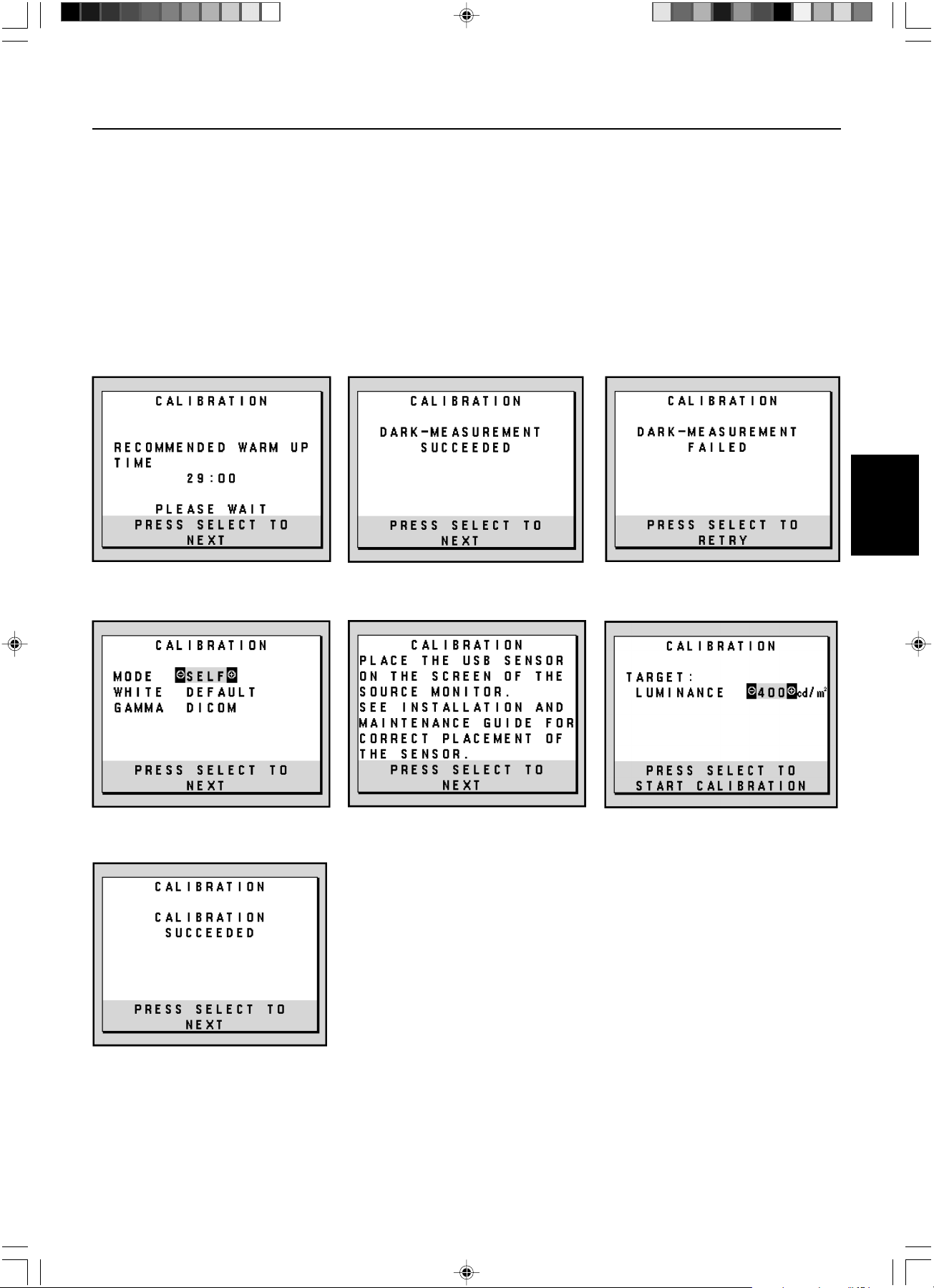
Deutsch.11
Deutsch
Selbstkalibrierung – Fortsetzung
8. Legen Sie die Zieleinstellung für die „LUMINANCE“ (LUMINISZENZ) (cd/m
2
) fest (Abbildung S.8).
9. Drücken Sie SELECT, um die Kalibrierung zu starten. Abhängig von den Benutzereinstellungen kann die Selbstkalibrierung einige
Minuten in Anspruch nehmen.
10. Wenn die Meldung „CALIBRATION SUCCEEDED“ (KALIBRIERUNG ERFOLGREICH) (Abbildung S.9) angezeigt wird, drücken
Sie die Taste SELECT.
11. Drücken Sie EXIT, um den Kalibrierungsmodus zu beenden.
Abbildung S.4 Abbildung S.5
Abbildung S.9
Abbildung S.3
Abbildung S.7 Abbildung S.8Abbildung S.6
02_MD21GS3MPINSTALL_DE.P65 08/08/2005, 12:0111
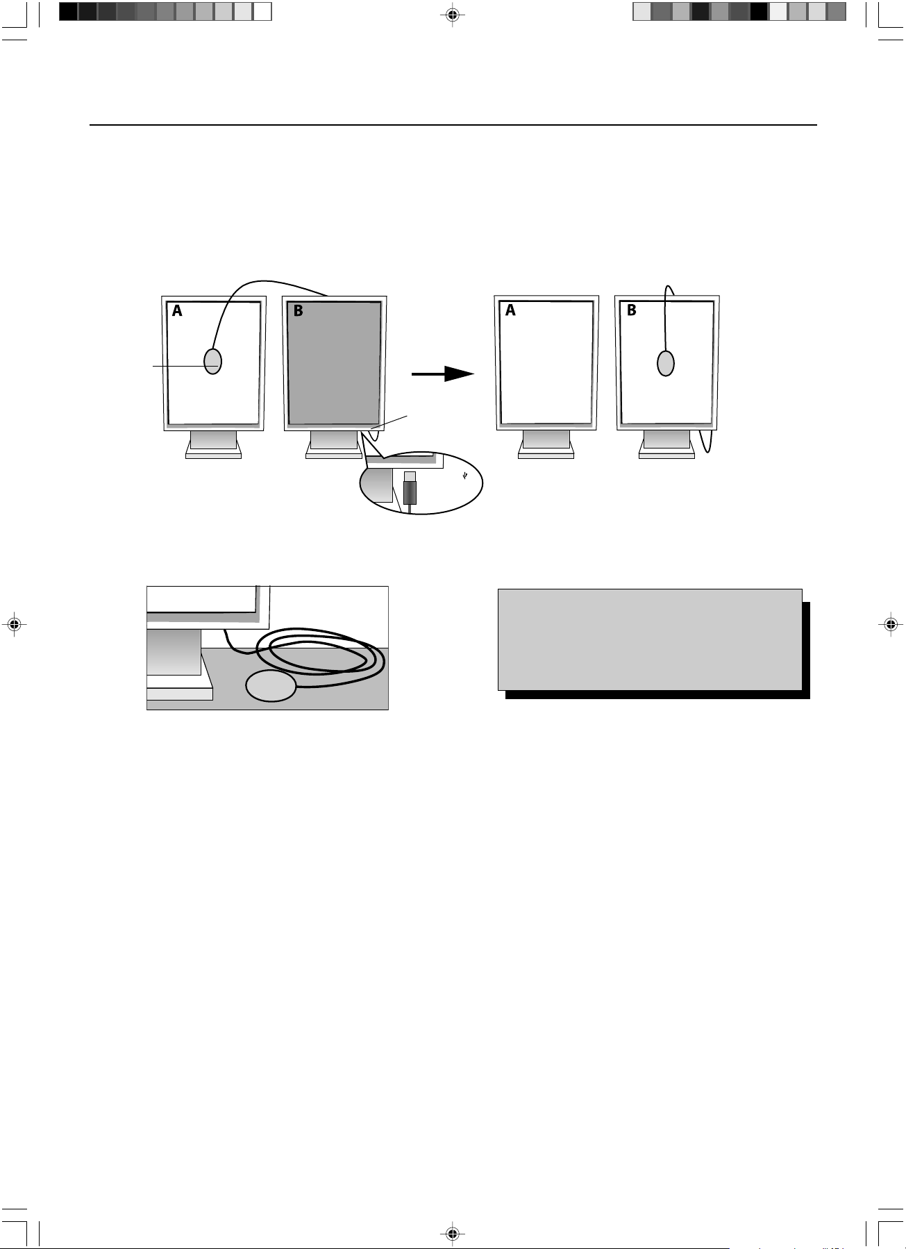
Deutsch.12
Verwenden Sie die Qualitätskontrollsoftware GammaComp MD für die Verwaltung historischer Daten (Beständigkeitstest). Damit die
kopierte Kalibrierung ordnungsgemäß durchgeführt werden kann, sollte der Monitor mindestens 30 Minuten warmlaufen. Wenn der
USB-Sensor eingesteckt wird, bevor der Monitor warmgelaufen ist, wird eine Warnmeldung auf dem Bildschirm angezeigt
(Abbildung C.4). HINWEIS:
Die eigenständige Kalibrierung kann nur mithilfe des GretagMacbeth Eye-One Display durchgeführt
werden
. Beachten Sie bitte die TASTENTABELLE (Abbildung A), wenn Sie Einstellungen während der Kalibrierung ändern.
1. Stecken Sie den USB-Sensor auf den Sensoranschluss (Abbildung C.1).
HINWEIS: Der Sensoranschluss kann nur für den USB-Sensor verwendet werden.
2. Das Kalibrierungsmenü wird automatisch geöffnet, und der USB-Sensor wird initialisiert. Nach der Initialisierung wird die Meldung
„DARK-MEASUREMENT“ (DUNKELHEITSMESSUNG) angezeigt. Sollte das nicht der Fall sein, fahren Sie bitte mit Schritt 5 fort.
3. Legen Sie den USB-Sensor mit der Oberseite nach unten auf eine nicht reflektierende, undurchsichtige Oberfläche (z. B. Schreibtisch
oder Mauspad), um den Schwarzwert zu messen (Abbildung C.3). Drücken Sie die Taste SELECT.
4. Nach erfolgreicher „DARK-MEASUREMENT“ (DUNKELHEITSMESSUNG) (Abbildung C.5) drücken Sie die Taste SELECT, um
fortzufahren. Wenn die „DARK-MEASUREMENT“ (DUNKELHEITSMESSUNG) fehlschlägt (Abbildung C.6), starten Sie den
Kalibrierungsvorgang neu bei Schritt 1.
5. Monitor A muss einen weißen Bildschirm anzeigen. Drücken Sie RESET und EXIT, um die erweiterten OSD Einstellungen zu öffnen.
Verwenden Sie die Tasten < und >, um zum MENÜPUNKT6 zu wechseln, und wählen Sie „SELF TEST MODE“ (SELBSTTESTMODUS).
6. Drücken Sie + oder –, um für den „MODE“ (MODUS) die Einstellung „COPY“ (KOPIE) auszuwählen (Abbildung C.7). Wählen Sie
unter „SELF“ (SELBST) die Einstellung EIN oder AUS. Wenn EIN eingestellt ist, wird die Selbstkalibrierung zusammen mit der kopierten
Kalibrierung durchgeführt.
7.
Wählen Sie die GAMMA-Zieleinstellung: „NO CORRECTION“ (KEINE KORREKTUR), DICOM, „LOG LINEAR“ (LINEARE ERFASSUNG),
„PROGRAMMABLE“ (PROGRAMMIERBAR) und „CUSTOM“ (BENUTZERDEFINIERT). Verwenden Sie bitte dieselbe GAMMA-
Zieleinstellung wie für Monitor A.
HINWEIS: Bei der Auswahl von „CUSTOM“ BENUTZERDEFINIERT kann der Gammawert im Bereich von 0.5 bis 4.0 in Schritten
von 0.1 geändert werden.
8. Sie werden aufgefordert, den USB-Sensor in der Mitte des Bildschirms zu platzieren (Abbildung C.8). Neigen Sie den Monitor um
etwa 5 Grad nach vorn, und platzieren Sie den USB-Sensor in der Mitte des Bildschirms (Abbildung C.1).
HINWEIS: Halten Sie den USB-Sensor flach auf den LCD-Bildschirm, um äußere Lichteinflüsse zu vermeiden.
Üben Sie dabei KEINEN DRUCK auf den Bildschirm aus. Drücken Sie die Taste SELECT.
Weißpunktabgleich/Kopierte Kalibrierung
Monitor A – Monitor, der als QUELLE für die zu kopierende Weißpunkteinstellung dient.
Monitor B – Zielmonitor, auf den die Kalibrierung kopiert werden soll.
Abbildung C.1
Abbildung C.2
Sensoranschluss
Abbildung C.3 Abbildung A
USB-
Sensor
USB-Symbol ( )
befindet sich auf
der anderen Seite
TASTENTABELLE
< / >: Wechselt von einer Einstellung zur nächsten.
– / +: Ändert die Auswahl für eine Einstellung
(d. h...SELBST oder KOPIE)
SELECT: Wechselt zum nächsten Schritt der Kalibrierung.
EXIT: Wechselt zum vorherigen Schritt der Kalibrierung.
02_MD21GS3MPINSTALL_DE.P65 08/08/2005, 12:0112
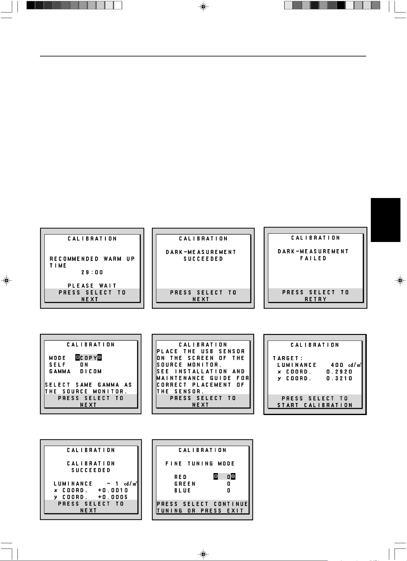
Deutsch.13
Deutsch
Weißpunktabgleich/Kopierte Kalibrierung – Fortsetzung
9. Drücken Sie am Monitor B die Taste SELECT, um das Lesen der Weißpunktinformationen von Monitor A zu starten.
10. Nach dem Kopieren der Informationen von Monitor A werden die Zieleinstellung für die „LUMINANCE“ (LUMINISZENZ) und der
Zielfarbort gespeichert und im OSD Fenster auf Monitor B angezeigt. Der „TARGET VALUE“ (ZIELWERT) kann nicht angepasst
werden (Abbildung C.9).
11. Entfernen Sie den USB-Sensor vom Quellmonitor A und platzieren Sie ihn in der Bildschirmmitte von Monitor B (Abbildung C.2).
12. Drücken Sie SELECT, um das Kopieren der Kalibrierung zu starten. Abhängig von den Benutzereinstellungen kann der
Kopiervorgang einige Minuten in Anspruch nehmen.
13. Nach erfolgreicher Kalibrierung sollten die Weißpunkte von Monitor A und Monitor B übereinstimmen. Wenn die Meldung
„CALIBRATION SUCCEEDED“ (KALIBRIERUNG ERFOLGREICH) (Abbildung C.10) angezeigt wird, drücken Sie die Taste SELECT, um
im „FINE TUNING MODE“ (OPTIMIERUNGSMODUS) fortzufahren.
14. Wenn die Meldung „FINE TUNING MODE“ (OPTIMIERUNGSMODUS) (Abbildung C.11) angezeigt wird, drücken Sie die Taste
EXIT, wenn Sie mit der Kalibrierung zufrieden sind. Wenn die Kalibrierung unbefriedigend ist, haben Sie zwei Möglichkeiten:
(A) Optimieren Sie den Weißpunkt manuell mit den Tasten + und –.
(B) Starten Sie die automatische Kopie der Kalibrierung neu, drücken Sie die Taste SELECT, und kehren Sie zu Schritt 3 zurück.
15. Drücken Sie EXIT, um den Kalibrierungsmodus zu beenden.
Abbildung C.5 Abbildung C.6
Abbildung C.10 Abbildung C.11
Abbildung C.4
Abbildung C.8 Abbildung C.9Abbildung C.7
02_MD21GS3MPINSTALL_DE.P65 08/08/2005, 12:0113
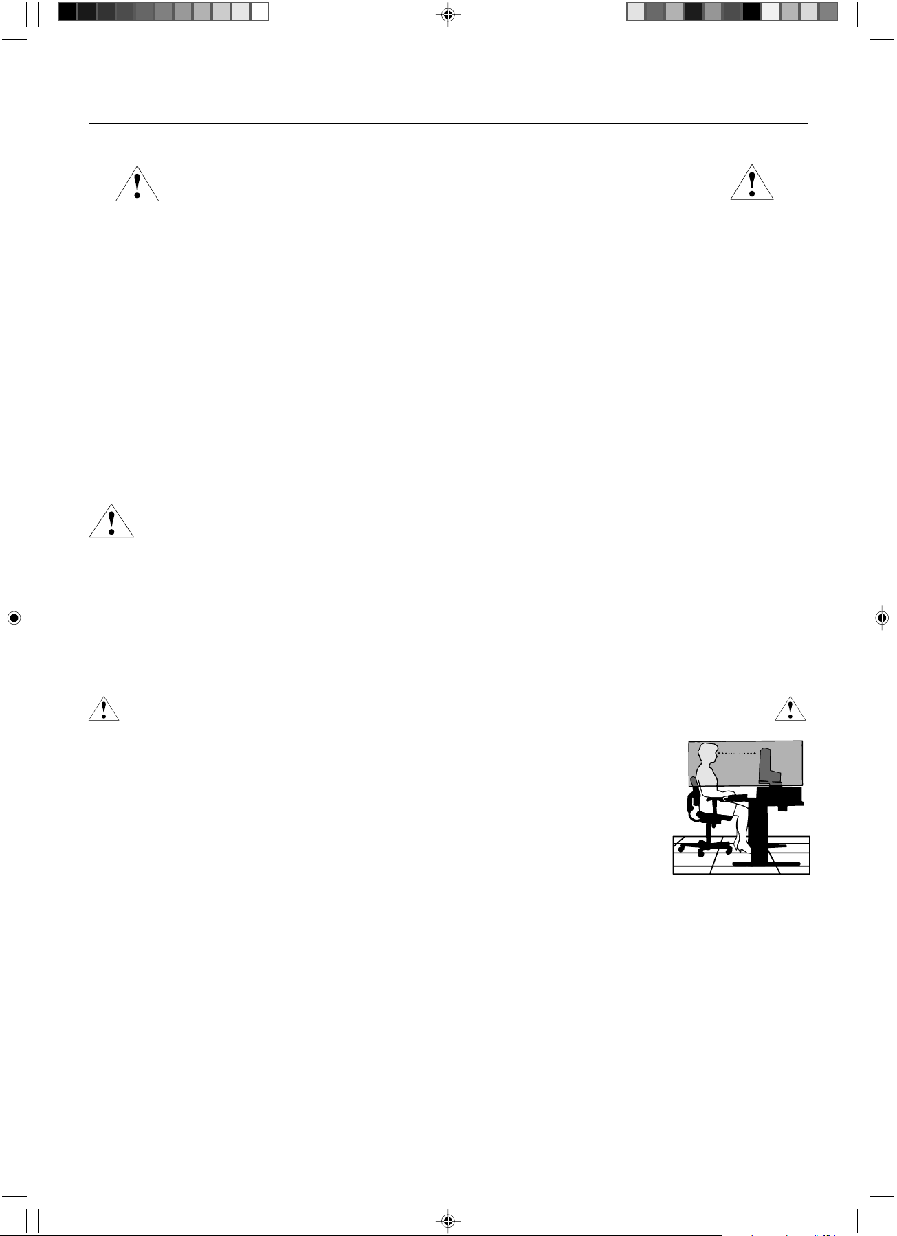
Deutsch.14
Sicherheitsvorkehrungen und Pflege
BEACHTEN SIE ZUR ERZIELUNG OPTIMALER LEISTUNG DIE FOLGENDEN
HINWEISE ZUM EINRICHTEN UND NUTZEN DES NEC MONITORS:
•ÖFFNEN SIE DEN MONITOR NICHT. Es befinden sich keine vom Benutzer zu wartenden Teile im Inneren. Das Öffnen oder Abnehmen der Abdeckungen
kann zu gefährlichen Stromschlägen führen und birgt weitere Risiken. Lassen Sie alle Wartungsarbeiten von qualifizierten Wartungstechnikern durchführen.
• Lassen Sie keine Flüssigkeiten in das Gehäuse gelangen, und stellen Sie den Monitor in trockenen Räumen auf.
• Führen Sie keinesfalls Objekte in die Gehäuseschlitze ein, da spannungsführende Teile berührt werden können, was zu schmerzhaften oder gefährlichen
Stromschlägen, zu Feuer oder zu Beschädigungen des Geräts führen kann.
• Legen Sie keine schweren Objekte auf das Netzkabel. Beschädigungen des Kabels können zu Stromschlägen oder Feuer führen.
• Stellen Sie dieses Produkt nicht auf wackelige oder instabile Flächen, Wagen oder Tische, da der Monitor fallen und dabei schwer beschädigt werden könnte.
• Stellen Sie keine Objekte auf den Monitor und setzen Sie den Monitor nicht außerhalb umbauter Räume ein.
• Im Inneren der Fluoreszenzröhre des Monitors befindet sich Quecksilber. Beachten Sie zur Entsorgung der Röhre die örtlichen Vorschriften und Richtlinien.
• Knicken Sie das Netzkabel nicht.
• Verwenden Sie den Monitor nicht in heißen, feuchten, staubigen oder öligen Bereichen.
• Decken Sie die Lüftungsschlitze des Monitors nicht ab.
Unter den folgenden Bedingungen müssen Sie den Monitor sofort vom Stromnetz trennen und sich mit einem qualifizierten Wartungstechniker in Verbindung setzen:
• Das Netzkabel oder der Netzstecker ist beschädigt.
• Flüssigkeit wurde über den Monitor gegossen oder Gegenstände sind in das Gehäuse gefallen.
• Der Monitor wurde Regen oder Wasser ausgesetzt.
• Der Monitor wurde fallen gelassen, oder das Gehäuse wurde beschädigt.
• Der Monitor arbeitet trotz Beachtung der Bedienungsanleitung nicht ordnungsgemäß.
• Seien Sie vorsichtig, wenn das Glas zerbrochen ist.
• Berühren Sie die Flüssigkristalle nicht, wenn der Monitor oder das Glas zerbrochen ist.
• Achten Sie auf ausreichende Luftzufuhr, damit die entstehende Wärme abgeführt werden kann. Decken Sie die Lüftungsschlitze nicht ab, und
stellen Sie den Monitor nicht neben Heizkörpern oder anderen Wärmequellen auf. Stellen Sie keine Gegenstände auf den Monitor.
• Durch Ziehen des Netzkabelsteckers kann das Gerät vom Stromnetz getrennt werden. Der Monitor muss in der Nähe einer Steckdose
aufgestellt werden, die leicht zugänglich ist.
• Transportieren Sie den Monitor vorsichtig. Bewahren Sie die Verpackung für spätere Transporte auf.
Bildschatten
Bei Geräten mit LCD-Technologie tritt ein Phänomen auf, das als Bildschatten bekannt ist. Bildschatten sind verbleibende oder sogenannte „Geister“-Bilder, die
vom vorhergehenden Bild sichtbar auf dem Bildschirm bleiben. Im Unterschied zu CRT-Monitoren ist der Bildschatten auf LCD-Monitoren nicht dauerhafter
Natur, aber die Anzeige von Standbildern über eine längere Zeit sollte vermieden werden. Sie können den Bildschatten beseitigen, indem Sie den Monitor so
lange ausschalten, wie das vorherige Bild angezeigt wurde. Wurde auf dem Monitor beispielsweise eine Stunde lang ein Standbild angezeigt und bleibt ein
„Geister“-Bild sichtbar, sollte der Monitor mindestens eine Stunde ausgeschaltet werden, damit der Bildschatten verschwindet.
HINWEIS: Wir empfehlen die Aktivierung eines Bildschirmschoners auf allen Anzeigegeräten, wenn sich das Bild längere Zeit nicht verändert. Schalten Sie
den Monitor aus, wenn Sie ihn nicht verwenden.
DURCH RICHTIGE AUFSTELLUNG UND EINSTELLUNG DES MONITORS KÖNNEN ERMÜDUNGSERSCHEINUNGEN VON AUGEN,
SCHULTERN UND NACKEN VERMIEDEN WERDEN. BEACHTEN SIE BEI DER AUFSTELLUNG DES MONITORS FOLGENDES:
• Bei der Selbstkalibrierung oder der kopierten Kalibrierung werden optimale Ergebnisse erst nach ca. 30 Minuten
Aufwärmzeit erzielt.
• Stellen Sie den Monitor so auf, dass sich die Oberkante des Bildschirms auf Augenhöhe oder knapp darunter befindet.
Ihre Augen sollten leicht nach unten gerichtet sein, wenn Sie auf die Bildschirmmitte blicken.
• Platzieren Sie den Monitor in einem Abstand von 40-70 cm von Ihren Augen. Der optimale Abstand beträgt 50 cm.
• Entspannen Sie Ihre Augen regelmäßig, indem Sie ein Objekt fokussieren, dass sich in einer Entfernung von mindestens
6 m befindet. Blinzeln Sie häufig.
• Stellen Sie den Monitor in einem 90°-Winkel zu Fenstern und anderen Lichtquellen auf, um Blendung und Reflexionen
zu verhindern. Neigen Sie den Monitor in einem Winkel, der Reflexionen der Deckenleuchten auf dem Bildschirm
verhindert.
• Reinigen Sie die Oberfläche des LCD-Monitors mit einem fusselfreien, weichen Tuch. Entfernen Sie hartnäckigen Schmutz
mit einem mit Wasser, Äthanol oder Isopropylalkohol getränkten Tuch. Verwenden Sie keine lösungsmittelhaltigen
Reinigungsmittel oder Glasreiniger (z. B. Säuren, Laugen und Aceton).
• Stellen Sie Helligkeit des Monitors mit der entsprechenden Taste ein, um die Lesbarkeit zu optimieren.
• Platzieren Sie das beim Tippen häufiger betrachtete Objekt (Monitor oder Dokumentenhalter) direkt vor Ihnen, damit Sie den Kopf seltener drehen müssen.
• Vermeiden Sie die längerfristige Darstellung gleichbleibender Muster auf dem Bildschirm, um Bildschatten zu vermeiden.
Ergonomie
Wir empfehlen folgendes Vorgehen, um eine ergonomisch optimale Arbeitsumgebung einzurichten:
• Verwenden Sie bei Standardsignalen die vordefinierten Größen- und Positionseinstellungen.
• Verwenden Sie Signale ohne Zeilensprung (Non-Interlaced) mit einer vertikalen Wiederholfrequenz von 60 Hz.
Reinigen des LCD-Bildschirms
• Wenn der Flüssigkristallbildschirm fleckig oder staubig ist, wischen Sie ihn mit einem weichen Tuch ab.
• Verwenden Sie zum Reinigen des LCD-Bildschirms keine harten oder kratzenden Materialien.
•Üben Sie keinen Druck auf die LCD-Oberfläche aus.
• Verwenden Sie keine Reinigungslösungen, da sie zur Beschädigung oder Verfärbung der LCD-Oberfläche führen können.
Reinigen des Gehäuses
• Ziehen Sie den Netzstecker aus der Steckdose.
• Wischen Sie das Gehäuse vorsichtig mit einem weichen Tuch ab.
• Reinigen Sie das Gehäuse zunächst mit einem mit neutralem Reinigungsmittel und Wasser getränkten Tuch, und wischen Sie mit einem trockenen Tuch nach.
HINWEIS: Die Gehäuseoberfläche besteht aus verschiedenen Kunststoffen. Verwenden Sie zum Reinigen NIEMALS Benzol, Verdünner, alkalische oder
alkoholhaltige Lösungsmittel, Glasreiniger, Wachs, Politur, Waschmittel oder Insektizide. Bringen Sie das Gehäuse nicht über längere Zeit mit Gummi
oder Vinyl in Berührung. Diese Flüssigkeiten und Stoffe können dazu führen, dass die Farbe beeinträchtigt wird und reißt oder abblättert.
Einsatzempfehlungen
VORSICHT
02_MD21GS3MPINSTALL_DE.P65 08/08/2005, 12:0114
Deutsch.15
Deutsch
Technische Daten
Technische Daten MD21GS-3MP Monitor Hinweise
LCD-Modul Diagonale: 54 cm/21,3 Zoll Aktivmatrix; Dünnschichttransistortechnologie
Sichtbare Bildgröße: 54 cm/21,3 Zoll (TFT) Flüssigkristallanzeige (LCD),
Native Auflösung (Pixelzahl): 1536 x 2048 (Hochformat) Lochmaske 0,2115 mm; 400 cd/m
2
2048 x 1536 (Querformat) kalibrierte Weißluminiszenz;
Kontrastverhältnis 700:1 (typ.)
Eingangssignal Video: Digitaler Eingang: DVI Bildpunkttakt 162 MHz max.
Graustufentöne 10 Bit: 1024 (10 Bit) Graustufen aus einer Bei Verwendung mit einer von empfohlenen
Palette von 3061 (11,5 Bit) 10-Bit-Grafikkarte
8 Bit: 256 (8 Bit) Graustufen aus einer Bei Verwendung mit einer von empfohlenen
Palette von 3061 (11,5 Bit) 8-Bit-Grafikkarte
Synchronisationsbereich Horizontal: 31,5 kHz bis 96,0 kHz Automatisch
Vertikal: 30 Hz, 50 Hz bis 85 Hz Automatisch
Betrachtungswinkel Links/Rechts: ±88° (CR > 10)
Auf/Ab: ±88° (CR > 10)
Bildaufbaugeschwindigkeit 35 ms (typ.)
Nutzbare Hochformat: Horiz.: 325 mm/12,8 Zoll
Bildschirmfläche Vert.: 433 mm/17,1 Zoll
Querformat: Horiz.: 433 mm/17,1 Zoll
Vert.: 325 mm/12,8 Zoll
Netzspannung Wechselstrom 100-240 V, ~ 50/60 Hz
Leistungsaufnahme 0,7 -0,35 A
Maße Hochformat: 358,7 mm (B) x 514 - 560 mm (H) x 200 mm (T)
14,1 Zoll (B) x 20,2 – 22,0 Zoll (H) x 7,9 Zoll (T)
Querformat: 467 mm (B) x 460 - 506 mm (H) x 200 mm (T)
18,4 Zoll (B) x 18,1 – 19,9 Zoll (H) x 7,9 Zoll (T)
Höheneinstellung: 46 mm/1,8 Zoll
Gewicht 11,7 kg/25,8 lbs
Umgebungsbedingungen
Betriebstemperatur: 5 °C bis 40 °C/41 °F bis 104 °F
Feuchtigkeit: 30 % bis 80 % (ohne Kondensation)
Höhenmeter: 0 bis 3.048 m/0 bis 10.000 Fuß
Lagertemperatur (in Verpackung): -20 °C bis 60 °C/-4 °F bis 140 °F
Luftfeuchtigkeit (in Verpackung): 10 % bis 85 % (ohne Kondensation)
Höhenmeter (in Verpackung): 0 bis 12.192 m/0 bis 40.000 Fuß
UL-Klassifizierung
Typ des Stromschlagschutzes: CLASS I
Grad des Stromschlagschutzes: Kein Patientenkontakt
Grad des Schutzes vor Wassereindringen nach IEC 529: Kein Schutz
Vom Hersteller empfohlene Sterilisations- oder Desinfektionsmethode: Keine Angabe
Grad der Sicherheit bei Anwendung bei Vorhandensein einer ENTFLAMMBAREN MISCHUNG AUS ANÄSTHETIKUM UND LUFT oder
MIT SAUERSTOFF ODER STICKOXID: Nicht geeignet
Betriebsmodus: Dauerbetrieb
02_MD21GS3MPINSTALL_DE.P65 08/08/2005, 12:0115

Deutsch.16
DVI-D: Die rein digitale Komponente der von der Digital Display Working Group (DDWG) definierten DVI-Schnittstelle für
digitale Verbindungen zwischen Computern und Anzeigegeräten. Da es sich um einen echten Digitalanschluss handelt,
werden analoge Signale nicht über einen DVI-D-Anschluss unterstützt. Die ausschließlich digitale Verbindung basiert auf
DVI. Deshalb wird nur ein einfacher Adapter benötigt, um die Kompatibilität zwischen DVI-D und anderen digitalen DVI-
Anschlüssen wie DFP und P&D zu gewährleisten.
P&D (Plug&Display): Der VESA-Standard für digitale Flachbildschirmschnittstellen. Dieser Standard ist stabiler als DFP, da
er den Einsatz anderer Optionen über einen Signalanschluss zulässt (beispielsweise USB, Analogvideo und IEEE-1394-
995). Das VESA-Komitee hat DFP als Teilmenge von P&D anerkannt. Die ausschließlich digitale Verbindung basiert auf
DVI. Deshalb wird nur ein einfacher Adapter benötigt, um die Kompatibilität zwischen P&D und anderen digitalen DVI-
Anschlüssen wie DFP und DVI zu gewährleisten.
Pivotfuß: Benutzer können die Ausrichtung des Monitors an den jeweiligen Einsatzbereich anpassen, also beispielsweise
das Querformat für breite Dokumente nutzen oder im Hochformat eine Seite vollständig auf dem Bildschirm anzeigen.
Weniger Stellplatz: Ideale Lösung für Umgebungen mit Größen- und Gewichtsbeschränkungen, für die gleichwohl eine
hervorragende Bildqualität benötigt wird. Die geringen Maße des Monitors und das geringe Gewicht erleichtern den
Transport von einem Standort zu einem anderen.
Bedienelemente für den OSD (On-Screen Display): Mit den erweiterten OSD Bedienelementen können Sie das Bild schnell
und einfach mit auf dem Bildschirm angezeigten Menüs einstellen. Mit der Funktion „OSD Abschaltung“ können alle OSD
Bedienelemente deaktiviert werden.
ErgoDesign-Merkmale: Durch Verbesserungen im Bereich der Ergonomie wird die Arbeitsumgebung optimiert. Dies führt
zu Einsparungen und schützt die Gesundheit der Benutzer. Beispiele sind die OSD Bedienelemente für schnelle und
problemlose Bildkorrekturen, der Kippfuß zur Anpassung des Sichtwinkels, die geringen Stellplatzanforderungen und die
Einhaltung der MPRII-Richtlinien für die Emissionsreduzierung.
Blendschutz und geringe Reflexion: Der Bildschirm verfügt über einen Blendschutz und reduziert die Reflexion der
Umgebung. Durch die verbesserte Wahrnehmung des Schwarzwerts des Bildschirms entsteht ein klareres Bild.
Mehrfrequenztechnologie: Automatische Anpassung des Monitors an die Zeilen- und Bildfrequenzen der Grafikkarte.
Dadurch wird immer die geforderte Auflösung erreicht.
FullScan-Funktion: In den meisten Auflösungen können Sie den vollen Anzeigebereich nutzen, also mit einem größeren
Bild arbeiten.
Weiter Betrachtungswinkel: Der Benutzer kann das Monitorbild im Quer- oder Hochformat innerhalb eines
Winkelbereichs von 176 Grad betrachten. Dieser Winkelbereich gilt sowohl vertikal als auch horizontal.
VESA-Standard-Montageadapter: Dieser Monitor kann an jedem Tragarm oder -bügel montiert werden, der dem VESA-
Standard entspricht. So können kompatible Montagevorrichtungen von Drittanbietern problemlos verwendet werden.
X-Light-Hintergrundbeleuchtung: Ein interner Sensor ermöglicht konsistente Helligkeits- und Weißpunkteinstellungen über
einen langen Zeitraum und liefert damit die Grundlage für ausgezeichnete Diagnosequalität. Das System ermöglicht auch
den Weißpunktabgleich zwischen mehreren Monitoren mithilfe eines Kalibrierungspucks (separat erhältlich), was zur
Kostenreduzierung und Effizienzsteigerung beiträgt.
Merkmale und Funktionen
02_MD21GS3MPINSTALL_DE.P65 08/08/2005, 12:0116

Deutsch.17
Deutsch
Fehlerbehebung
Kein Bild
• Das Signalkabel muss richtig mit Grafikkarte/Computer verbunden sein.
• Die Grafikkarte muss richtig in den Steckplatz eingesetzt sein.
• Der Netzschalter muss sich in der Position ON befinden.
• Der Netzschalter des Computers muss sich in der Position ON befinden.
•Überprüfen Sie, ob ein von der verwendeten Grafikkarte unterstützter Modus ausgewählt wurde.
(Informationen zum Ändern des Grafikmodus finden Sie im Handbuch zur Grafikkarte bzw. zum System.)
•Überprüfen Sie, ob für Monitor und Grafikkarte die empfohlenen Einstellungen vorgenommen wurden.
• Prüfen Sie, ob der Stecker des Signalkabels verbogen wurde oder ob Stifte im Stecker fehlen.
Netzschalter reagiert nicht
• Ziehen Sie das Netzkabel des Monitors aus der Steckdose, um den Monitor auszuschalten und zurückzusetzen.
•Überprüfen Sie den Netzschalter auf der oberen (Hochformat) oder linken (Querformat) Seite des Monitors.
Bildschatten
• Bei Geräten mit LCD-Technologie tritt ein Phänomen auf, das als Bildschatten bekannt ist. Bildschatten sind verbleibende oder
sogenannte „Geister“-Bilder, die vom vorhergehenden Bild sichtbar auf dem Bildschirm bleiben. Im Unterschied zu CRT-Monitoren
ist der Bildschatten auf LCD-Monitoren nicht dauerhafter Natur, aber die Anzeige von Standbildern über eine längere Zeit sollte
vermieden werden. Sie können den Bildschatten beseitigen, indem Sie den Monitor so lange ausschalten, wie das vorherige Bild
angezeigt wurde. Wurde auf dem Monitor beispielsweise eine Stunde lang ein Standbild angezeigt und bleibt ein „Geister“-Bild
sichtbar, sollte der Monitor mindestens eine Stunde ausgeschaltet werden, damit der Bildschatten verschwindet.
HINWEIS: Wir empfehlen die Aktivierung eines Bildschirmschoners auf allen Anzeigegeräten, wenn sich das Bild längere Zeit
nicht verändert. Schalten Sie den Monitor aus, wenn Sie ihn nicht verwenden.
Die Meldung „FREQUENZ ZU HOCH” wird angezeigt (Bildschirm ist entweder dunkel oder zeigt nur ein undeutliches Bild)
• Bild erscheint undeutlich (Pixel fehlen) und die OSD Meldung „FREQUENZ ZU HOCH” wird angezeigt: Das bedeutet, dass der
Signaltakt oder die Auflösung zu hoch ist. Wechseln Sie in einen unterstützten Modus.
• Auf dem leeren Bildschirm wird die OSD Meldung „OUT OF RANGE“ (Frequenz zu hoch) angezeigt: Die Signalfrequenz liegt
außerhalb des zulässigen Bereichs. Wechseln Sie in einen unterstützten Modus.
Bild ist nicht stabil, unscharf oder verschwimmt
• Das Signalkabel muss richtig mit dem Computer verbunden sein.
•Überprüfen Sie, ob für Monitor und Grafikkarte die empfohlenen Signaltimings eingestellt wurden und ob die Geräte kompatibel sind.
• Ist der Text verstümmelt, aktivieren Sie einen Videomodus ohne Zeilensprung (Non-Interlaced) und eine Wiederholfrequenz von 60 Hz.
Bild wird nicht in der richtigen Größe angezeigt
•Überprüfen Sie, ob ein von der verwendeten Grafikkarte unterstützter Modus ausgewählt wurde.
(Informationen zum Ändern des Grafikmodus finden Sie im Handbuch zur Grafikkarte bzw. zum System.)
•Überprüfen Sie den EXPANSIONSMODUS im OSD Menü.
Kein Bild
• Wird auf dem Bildschirm kein Bild angezeigt, schalten Sie den Monitor aus und wieder ein.
• Stellen Sie sicher, dass sich der Monitor nicht im Stromsparmodus befindet (drücken Sie eine Taste oder bewegen Sie die Maus).
Monitor lässt sich nicht neigen
• Drehen Sie den Bildschirm um 90° im Uhrzeigersinn, bis es ein Mal klickt.
• Informationen zur korrekten Anbringung des Fußes finden Sie im Abschnitt Einstellung und Montage des Monitors.
Kein OSD Menü
• Lesen Sie bitte die Informationen zur OSD Abschaltung im Abschnitt Erweiterte OSD Einstellungen.
02_MD21GS3MPINSTALL_DE.P65 08/08/2005, 12:0117

Deutsch.18
Referenz
Nordamerika und Kanada
NEC Monitor Kundendienst & Support
Kundendienst und technischer Support: (800) 632-4662
Fax: (801) 907-3805
Ersatzteile und Zubehör/Macintosh
Kabeladapter: (800) 632-4662
Garantieinformationen: www.necdisplay.com
Online-Support www.necdisplay.com
Vertriebs- und Produktinformationen
Hotline Vertriebsinformationen: (888) 632-6487
Für kanadische Kunden: (866) 771-0266, Durchwahl: 4037
Vertrieb an Behörden: (800) 284-6320
Vertrieb an Behörden – E-Mail: gov@necdisplay.com
Elektronische Informationskanäle
World Wide Web: www.necdisplay.com
Produktregistrierung: www.necdisplay.com
Treiber und Downloads www.necdisplay.com
Europa
Adresse
NEC Display Solutions Europe GmbH Telefon: +49(0)89 99699 - 0
Landshuter Allee 12 -14
D-80637 München
Elektronische Informationskanäle
World Wide Web: www.medical.nec-display-solutions.com
02_MD21GS3MPINSTALL_DE.P65 08/08/2005, 12:0118
Deutsch.19
Deutsch
KONFORMITÄTSERKLÄRUNG
Für die USA
Dieses Gerät entspricht Abschnitt 15 der FCC-Richtlinien. Beim Betrieb müssen die beiden folgenden Bedingungen erfüllt sein. (1) Das Gerät
darf keine unerwünschten Störgrößen aussenden. (2) Das Gerät muss empfangene Störgrößen aufnehmen können, auch wenn diese
Funktionsstörungen verursachen.
Produkttyp: Computermonitor
Geräteklassifizierung: Peripheriegerät der Klasse B
Modell:
MD21GS-3MP-CB/MD21GS-3MP-BB
Wir erklären hiermit, dass das oben angegebene
Gerät den technischen Standards der FCC-Richtlinien entspricht.
FCC-Hinweis
1.Verwenden Sie mit dem Graustufenmonitor MD21GS-3MP die fest montierten bzw. angegebenen Kabel, um Störungen des Rundfunk-
bzw. Fernsehempfangs zu vermeiden.
(A) Verwenden Sie das mitgelieferte oder ein gleichwertiges Netzkabel, damit die FCC-Konformität gewährleistet ist.
(B) Verwenden Sie das mitgelieferte abgeschirmte Videosignalkabel.
Die Verwendung anderer Kabel und Adapter kann zu Störungen des Rundfunk- und Fernsehempfangs führen.
2.Dieses Gerät wurde getestet und hält die Grenzwerte für digitale Geräte der Klasse B gemäß Abschnitt 15 der FCC-Richtlinien ein.
Diese Grenzen gewährleisten bei der Installation in Wohngebieten einen ausreichenden Schutz vor Störungen. Dieses Gerät kann
Energie im HF-Bereich erzeugen, verwenden und abstrahlen. Wird es nicht nach Maßgabe der Bedienungsanleitung installiert, kann es
zu Störungen der Kommunikation im HF-Bereich kommen. Es ist jedoch nicht garantiert, dass unter keinen Bedingungen Störungen
auftreten. Treten bei Verwendung dieses Geräts Störungen des Rundfunk- oder Fernsehempfangs auf (dies ist durch Aus- und Einschalten
des Geräts festzustellen), empfehlen wir eine Behebung der Störung durch die folgenden Maßnahmen:
• Richten Sie die Empfangsantenne neu aus oder stellen Sie sie andernorts auf.
• Vergrößern Sie den Abstand zwischen diesem Gerät und dem Empfänger.
• Schließen Sie das Gerät an einen anderen Stromkreis als den Empfänger an.
• Setzen Sie sich mit Ihrem Händler in Verbindung oder fragen Sie einen erfahrenen Rundfunk-/Fernsehtechniker um Rat.
Der Benutzer sollte sich gegebenenfalls mit seinem Händler oder einem erfahrenen Rundfunk-/Fernsehtechniker in Verbindung setzen, um
weitere Möglichkeiten zu erfragen. Nützliche Hinweise enthält auch die folgende Broschüre der Federal Communications Commission: „How
to Identify and Resolve Radio-TV Interference Problems“. Diese Broschüre können Sie unter der Bestellnummer 004-000-00345-4 vom U.S.
Government Printing Office, Washington, D.C., 20402, anfordern.
Für Europa
Konformitätserklärung
Geräteklassifizierung: Klasse I, nicht messende Funktion
Anwendbare Regeln: Annex IX, Regeln 1.4 (Abschnitt 1) und 1.1 (Abschnitt 3)
Produktname: NEC MD21GS-3MP
21.3” Graustufen-LCD-Monitor zur Bilddiagnose
Modellnummern: MD21GS-3MP-BK-BB (Blue Base)
MD21GS-3MP-BK-CB (Clear Base)
UMDNS-Code: 16-603
NEC Display Solutions Europe GmbH erklärt hiermit, dass die aufgeführten Produkte den Anforderungen und Bestimmungen der
Ratsdirektive 93/42/EEC und den anwendbaren Klauseln der folgenden Standards entsprechen:
– EN 60601-1
– EN 60601-1-2
– EN 61000-3-2
– EN 61000-3-3
NEC Display Solutions Europe GmbH
Landshuter Allee 12-14. 80637 München, Deutschland
Für Kanada
Konformitätserklärung - Canadian Department of Communications
DOC: Dieses digitale Gerät der Klasse B erfüllt alle Anforderungen der kanadischen Richtlinien zu funkstörenden Geräten.
C-UL: Trägt die Kennzeichnung C-UL und erfüllt die kanadischen Sicherheitsrichtlinien nach CAN/CSA C22.2 Nr. 601.1.
Verantwortlich in den USA: NEC Display Solutions of America, Inc.
Adresse: 500 Park Blvd, Suite 1100
Itasca, Illinois 60143
Telefon: Nr.: (630) 467-3000
02_MD21GS3MPINSTALL_DE.P65 08/08/2005, 12:0119

Deutsch.20
02_MD21GS3MPINSTALL_DE.P65 08/08/2005, 12:0120
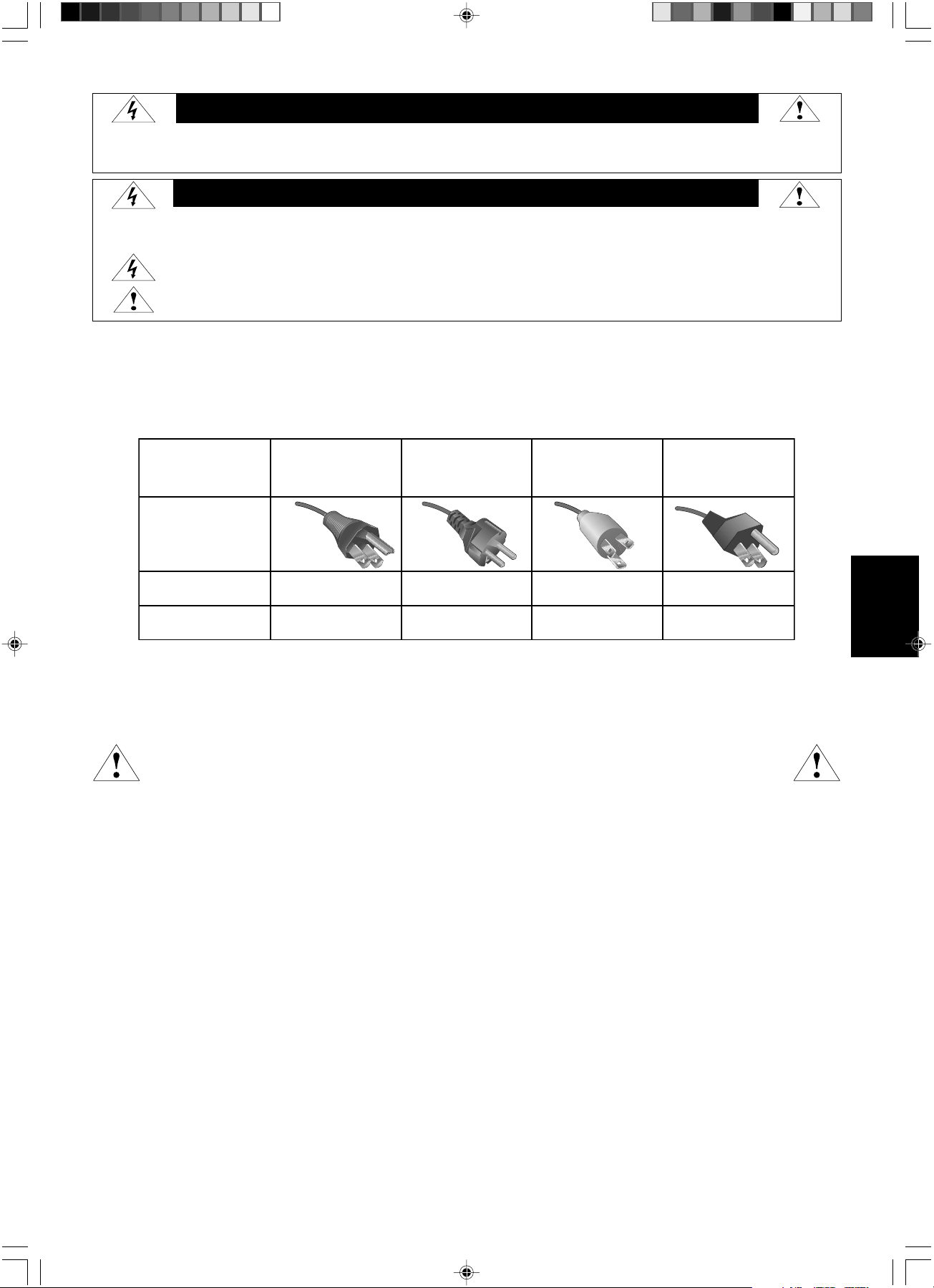
Français.1
Français
Informations importantes concernant le cordon d’alimentation
ATTENTION : Veuillez utiliser le cordon d’alimentation fourni avec le présent écran conformément au tableau ci-dessous. Si aucun
cordon d’alimentation n’est fourni avec ce matériel, veuillez contacter votre fournisseur. Dans tous les autres cas, veuillez utiliser un
cordon d’alimentation conforme aux normes de sécurité et à la tension en vigueur dans votre pays.
Si vous utilisez cet écran en Amérique du nord, vous devrez utiliser un cordon d’alimentation approprié (North America Hospital Grade).
Utilisation de conception
L’écran d’affichage en nuances de gris MD21GS-3MP est conçu pour l’affichage et le visionnage d’images numériques permettant
l'établissement de diagnostics par des physiciens qualifiés. Pour assurer une performance optimale de l’écran, telle que spécifiée, il
doit être utilisé uniquement en association avec les cartes graphiques NEC recommandées.
Pour les clients européens
Le déballage, l’installation et le réglage de l’affichage de cet écran ne doivent être effectués que par un personnel
agréé qualifié. Toute installation effectuée par une personne non agréée se fera à ses propres risques et nous
déclinons toute responsabilité en cas de dysfonctionnement de l’appareil.
Imagerie médicale
Le NEC MD21GS-3MP est conçu pour une imagerie médicale en nuances de gris de 3 mégapixels (1536 x 2048). Le réglage complet de
cet écran s’effectue grâce à un paramètre de correction de gamma conforme à la norme DICOM Part 14.
Tous les noms de marques et de produits sont des marques commerciales ou des marques déposées par leurs propriétaires respectifs.
AVERTISSEMENT
POUR EVITER LES RISQUES D’INCENDIE OU D’ELECTROCUTION, N’EXPOSEZ PAS L’APPAREIL A LA PLUIE OU A L’HUMIDITE. DE MEME, N’UTILISEZ PAS LA PRISE
POLARISEE DE CET APPAREIL AVEC UNE RALLONGE OU D’AUTRES PRISES SI ELLES NE PEUVENT ETRE TOTALEMENT ENFONCEES.
N’OUVREZ PAS LE BOITIER CAR IL CONTIENT DES COMPOSANTS A HAUTE TENSION. CONFIEZ TOUS LES TRAVAUX DE DEPANNAGE A DU PERSONNEL TECHNIQUE QUALIFIE.
POUR RÉDUIRE LES RISQUES D’ÉLECTROCUTION, VÉRIFIEZ QUE LE CORDON D’ALIMENTATION EST BIEN DÉBRANCHÉ DE LA PRISE MURALE. POUR
SUPPRIMER TOUTE ALIMENTATION DE L’APPAREIL, VEUILLEZ DÉCONNECTER LE CORDON D’ALIMENTATION DE LA PRISE SECTEUR. N’ENLEVEZ PAS
LE COUVERCLE (OU L’ARRIÈRE). VOUS NE POUVEZ RÉPARER AUCUNE PIÈCE INTERNE. CONFIEZ TOUS LES TRAVAUX DE DÉPANNAGE À DU
PERSONNEL TECHNIQUE QUALIFIÉ.
Ce symbole prévient l’utilisateur qu’une tension non isolée dans l’appareil peut être suffisante pour provoquer une électrocution.
Il est donc dangereux d’établir le moindre contact avec une pièce située à l’intérieur de cet appareil.
Ce symbole prévient l’utilisateur que des documents importants sur l’utilisation et le dépannage de cet appareil sont fournis avec celui-ci.
Ils doivent donc être lus attentivement pour éviter tout problème.
ATTENTION
ATTENTION :
Type de prise
Européenne
continentale
Chinoise
Nord américaine
Hospital Grade
Japonaise
(pour le marché japonais
uniquement)
Forme de prise
Pays
Tension
120 230 220 100
Etats-Unis/Canada
Europe
(sauf Royaume-Uni)
Chine Japon
(point et
étiquette verts)
03_MD21GS3MPINSTALL_FR.P65 08/08/2005, 12:011

Français.2
Cordon d’alimentation
Câble de signal vidéo
Guide abrégé de référence
Guide d’installation
et de maintenance
Noyau de ferrite
La boîte* de votre nouvel écran LCD NEC doit contenir les éléments suivants :
• Ecran MD21GS-3MP avec support ajustable en inclinaison/pivotement/rotation/hauteur
• Cordon d’alimentation
• Guide abrégé de référence
• Guide d’installation et de maintenance
• Câble de signal vidéo (câble DVI-D vers DVI-D)
• Noyau de ferrite
*2
• CD-ROM
Pour des instructions complètes concernant la carte graphique, veuillez vous reporter au guide d’installation de la cartegraphique.
En ce qui concerne le logiciel de contrôle de qualité GammaComp MD, veuillez vous reporter au Guide de l’utilisateur GammaComp MD.
*N’oubliez pas de conserver la boîte et le matériel d’emballage d’origine pour transporter ou expédier le moniteur
.
*
2
Pour cordon d’alimentation (type européenne continentale ou chinoise)
Sommaire
Ouvrir le noyau de ferrite et serrez-
le autour du cordon d’alimentation.
Refermer le noyau de
ferrite.
Fixer le noyau de ferrite à l'extrémité du cordon d’alimentation.
Uniquement du côté de l’entrée de l’alimentation du moniteur (connecteur AC-IN).
Noyau de ferrite
Noyau de ferrite
CD-ROM
03_MD21GS3MPINSTALL_FR.P65 08/08/2005, 12:012
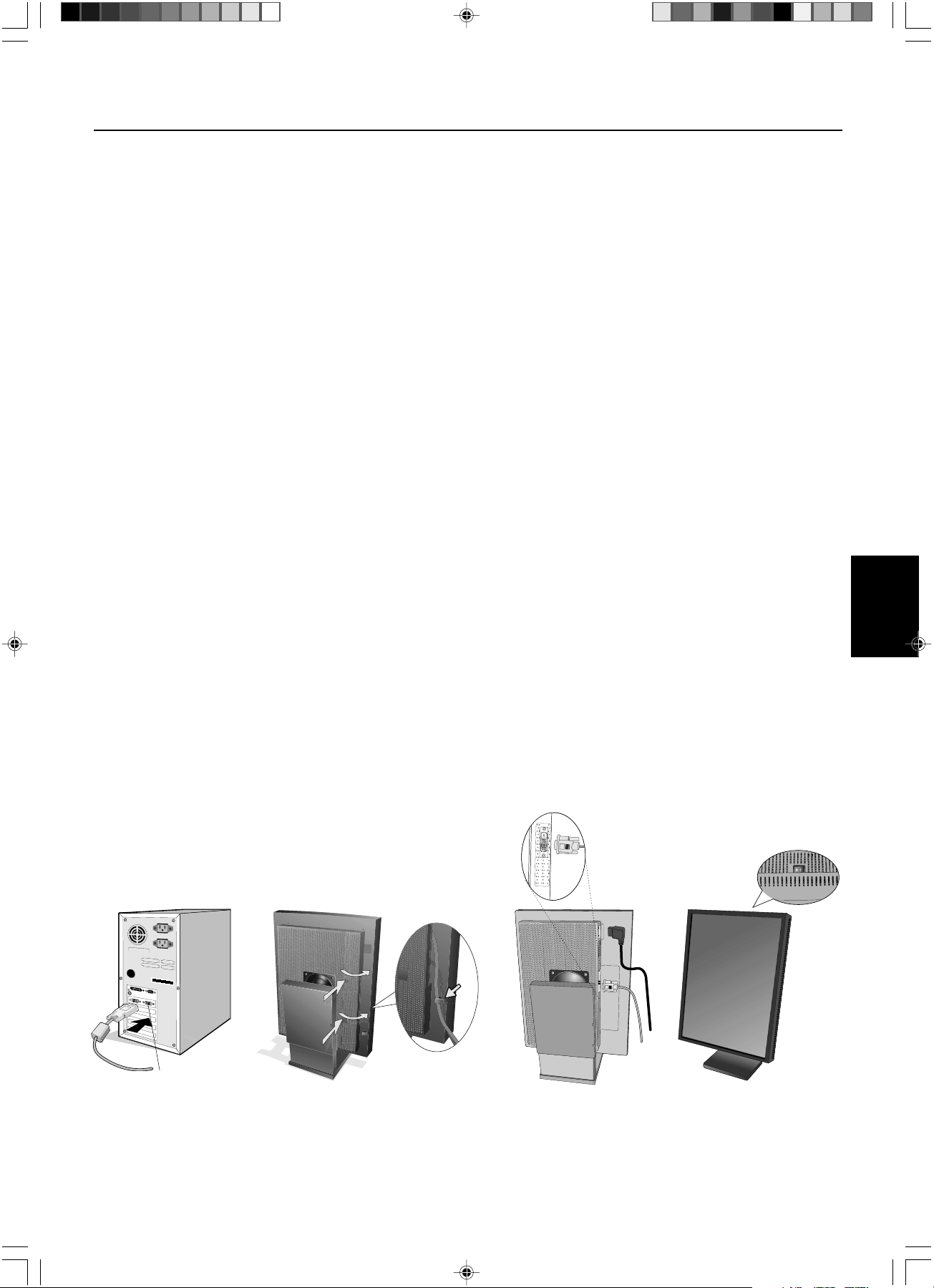
Français.3
Français
Installation d’une carte graphique
1.
En respectant les indications du fabricant de votre PC, ouvrez votre ordinateur pour accéder aux emplacements PCI, AGP ou PCI E.
2. Placez la carte d’affichage dans un slot PCI disponible et resserrez toutes les vis.
3. Remettez le couvercle de l’unité centrale en place.
REMARQUE : Pour configurer les informations sur les pilotes, les options d’affichage en mode multi moniteurs et le commutateur de
plongée, veuillez vous référer à la documentation fournie par le fabricant de la carte d’affichage.
Branchement du LCD à votre PC
Une fois réussie l’installation de la carte graphique, suivez les instructions suivantes pour brancher l’écran à votre PC.
1. Fermez votre ordinateur et mettez-le hors tension.
2. Branchez le câble signal DVI-D au connecteur de la carte graphique de votre système (Figure A.1).
REMARQUE : Pour des affichages en duo, branchez un câble DVI-D au port 1 ou 2 de la carte graphique (Figure A.1). Pour obtenir
plus de détails sur l’installation d’une carte graphique, veuillez consulter le manuel de la carte graphique. Serrez
toutes les vis.
3. Enlevez la gaine de câble en appuyant sur les deux pattes pour la libérer. Soulevez la gaine pour l’enlever (Figure B.1).
4. Connectez le câble signal DVI-D au connecteur à l’arrière de l’écran (Figure C.1).
REMARQUE : Une mauvaise connexion des câbles risque de provoquer une panne, d’endommager des composants, de nuire à la
qualité d’affichage du module LCD ou encore de réduire la durée de vie du module.
5. Connectez une extrémité du cordon d’alimentation à l’arrière du moniteur et l’autre à la prise de courant (Figure C.1). Remettez la
gaine de câble en place.
REMARQUE : Reportez-vous à la section Ajustement et montage de l’écran pour vérifier l’inclinaison, élever et abaisser l’écran du
moniteur et vérifier la rotation de l’écran lors de la gestion des câbles et du cordon d’alimentation.
REMARQUE
: Veuillez vous reporter à la section Attention de ce manuel pour le choix d’un cordon d’alimentation CA adapté.
6. Regroupez les câbles et le cordon d’alimentation et placez-les sous la barrette de câblage (Figure B.1).
REMARQUE : Libérez les câbles de la barrette avant d’enlever la gaine du câble.
7. Allumez le moniteur avec le commutateur sur le dessus (portrait) ou le côté gauche (paysage) du moniteur (Figure D.1).
Allumez l’ordinateur.
REMARQUE : Veuillez NE PAS allumer et éteindre le moniteur répétitivement.
8. Pour de plus amples ajustements, veuillez vous référer à la section OSD qui décrit en détail les commandes OSD.
REMARQUE : En cas de problème, référez-vous à la section Dépannage.
REMARQUE : Les équipements externes, destinés à des connexions à un signal d’entrée, à un signal de sortie, ou à d’autres
connecteurs, doivent se conformer à la norme IEC appropriée.
Mise en marche rapide
Figure C.1
Figure A.1
Port 2 pour moniteur en duo
Figure B.1
Figure D.1
Attache
03_MD21GS3MPINSTALL_FR.P65 08/08/2005, 12:013
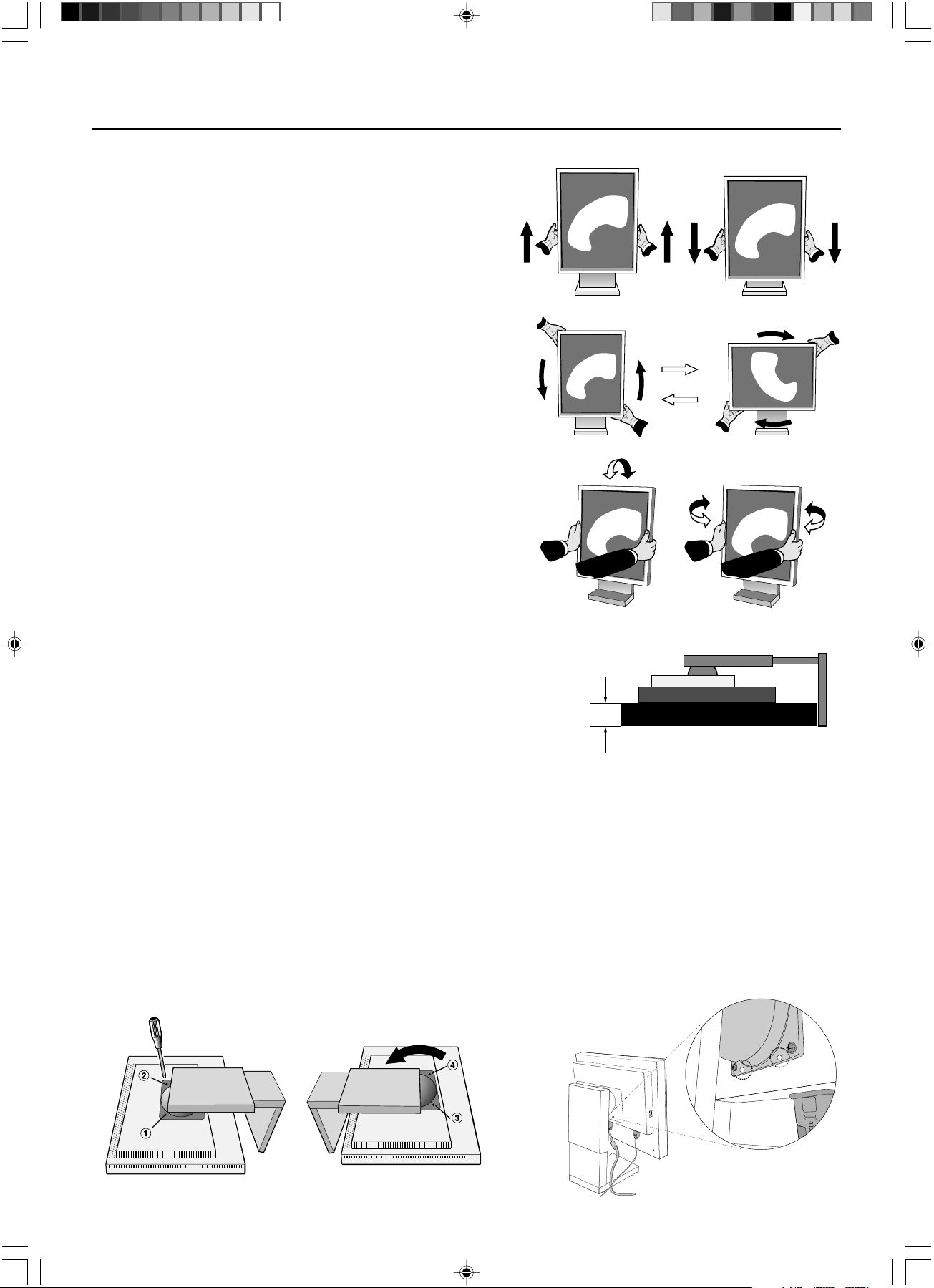
Français.4
Ajustement et montage de l’écran
Élévation et abaissement de l’écran du moniteur
L’écran peut être élevé ou abaissé en mode portrait ou paysage. Pour
élever ou abaisser l’écran, placez les mains de chaque côté et élevez ou
abaissez ce dernier à la hauteur qui vous convient.
REMARQUE : Manipulez l’écran du moniteur avec précaution lorsque
vous l’élevez ou l’abaissez et évitez de vous pincer les
doigts.
Rotation de l’écran
Avant de tourner l’écran, celui-ci doit être levé au niveau maximum afin
d’éviter tout choc de l’écran contre le support ou tout pincement de doigts.
Pour tourner l’écran, placez les mains de chaque côté et tournez dans le sens
des aiguilles d’une montre, du mode paysage au mode portrait, ou contre le
sens des aiguilles d’une montre, du mode portrait au mode paysage. Pour
faire passer le menu OSD de la position paysage à portrait ou inversement,
reportez-vous, dans la section « OSD », à la rubrique sur la fonction « Rota-
tion OSD ».
Inclinaison et pivotement
Empoignez fermement les côtés gauche et droit de l’écran du
moniteur et réglez l’inclinaison et/ou le pivotement comme désiré.
REMARQUE :Manipulez l’écran avec précaution lorsque vous l’inclinez.
Montage alternatif VESA LCD
1. Déconnectez tous les câbles.
2. Placez les mains de chaque côté de l’écran et levez ce dernier jusqu’à la position
la plus haute. Tournez l’écran de 90° contre le sens des aiguilles d’une montre
pour le mettre en position paysage.
3. Posez l’écran à plat sur une surface non abrasive en position paysage.
Placez l’écran sur une plate-forme d’au moins 29 mm de manière à ce que le
support soit parallèle à la surface (Figure S.1).
4. Retirez les deux vis du haut qui rattachent l’écran au support (Figure S.2).
Tournez le support de 180° contre le sens des aiguilles d’une montre (deux déclics
doivent se faire entendre). Retirez les vis du bas (Figure S.3) et ôtez le support.
L’écran est maintenant prêt pour un montage différent.
5. Inversez cette procédure pour fixer à nouveau le support : revissez les deux vis du bas, tournez le support de 180° contre le sens
des aiguilles d’une montre (deux déclics doivent se faire entendre) et revissez les deux vis du haut.
REMARQUE : Utilisez uniquement une méthode de montage alternative compatible VESA (pas de 100 mm).
REMARQUE : Manipulez l’écran avec soin pour retirer le support.
REMARQUE : Quand l’écran est en position paysage, assurez-vous que les deux encoches rondes sont placées au bas de l’écran
(Figure S.4).
ATTENTION : Veuillez utiliser les vis originales (4 vis ) lors du montage pour éviter d’endommager l’écran et le support. Afin de
respecter les prescriptions relatives à la sécurité, l’écran doit être monté sur un bras garantissant la stabilité nécessaire
en fonction du poids de l’écran. L’écran doit être uniquement utilisé avec un bras homologué (par exemple, portant la
marque GS).
Figure S.4Figure S.3Figure S.2
Figure S.1
29 mm
03_MD21GS3MPINSTALL_FR.P65 08/08/2005, 12:014
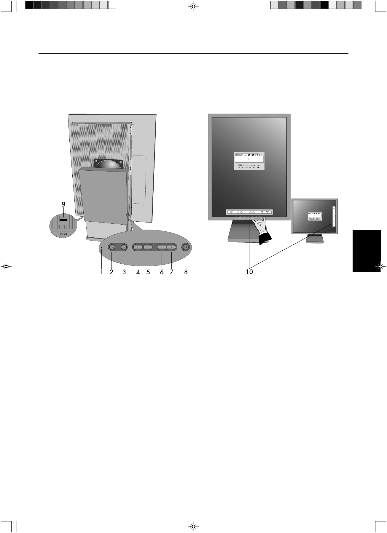
Français.5
Français
Commandes utilisateur
Les boutons de commande OSD (On-Screen Display) sont situés à l’arrière du moniteur. Pour accéder au menu de l’OSD,
pressez l’un des boutons de commande utilisateur (<, >, –, +).
1. Témoin LED Indique que la mise sous tension de l’appareil et les conditions de signal. Le témoin LED peut être
allumé, éteint ou diffus. Veuillez vous reporter à la section OSD avancée, à la rubrique
Luminosité du témoin, pour de plus amples informations.
Vert – signal présent et appareil sous tension
Orange – absence de signal
2. RESET Ramène la commande en surbrillance à son réglage par défaut (sortie d’usine).
3. SELECT Donne accès aux commandes et au sous-menu OSD.
4/5. ADJUST -/+ Déplace la barre vers la gauche ou la droite pour augmenter ou diminuer le réglage.
6/7. CONTROL </> Déplace vers la gauche ou vers la droite la zone en surbrillance pour le choix des menus de
commande.
Déplace vers le haut ou vers le bas la zone en surbrillance pour le choix des commandes.
8. EXIT (Sortie) Quitte les commandes OSD et le menu principal.
9. Port capteur Pour un capteur externe optionnel utilisé en auto calibrage et en calibrage de copie.
10. A l’écran Key Guide L’aide sur les commandes s’affiche automatiquement à l’écran lorsqu’une des touches de
commande retour est utilisée. L’aide sur les commandes change d’orientation avec l’OSD.
REMARQUE : Quand vous appuyez sur RESET dans le menu principal ou dans un sous-menu, une fenêtre
d’avertissement apparaît pour vous permettre d’annuler la fonction de réinitialisation en appuyant sur le
bouton EXIT.
Mode portrait
Mode paysage
03_MD21GS3MPINSTALL_FR.P65 08/08/2005, 12:015
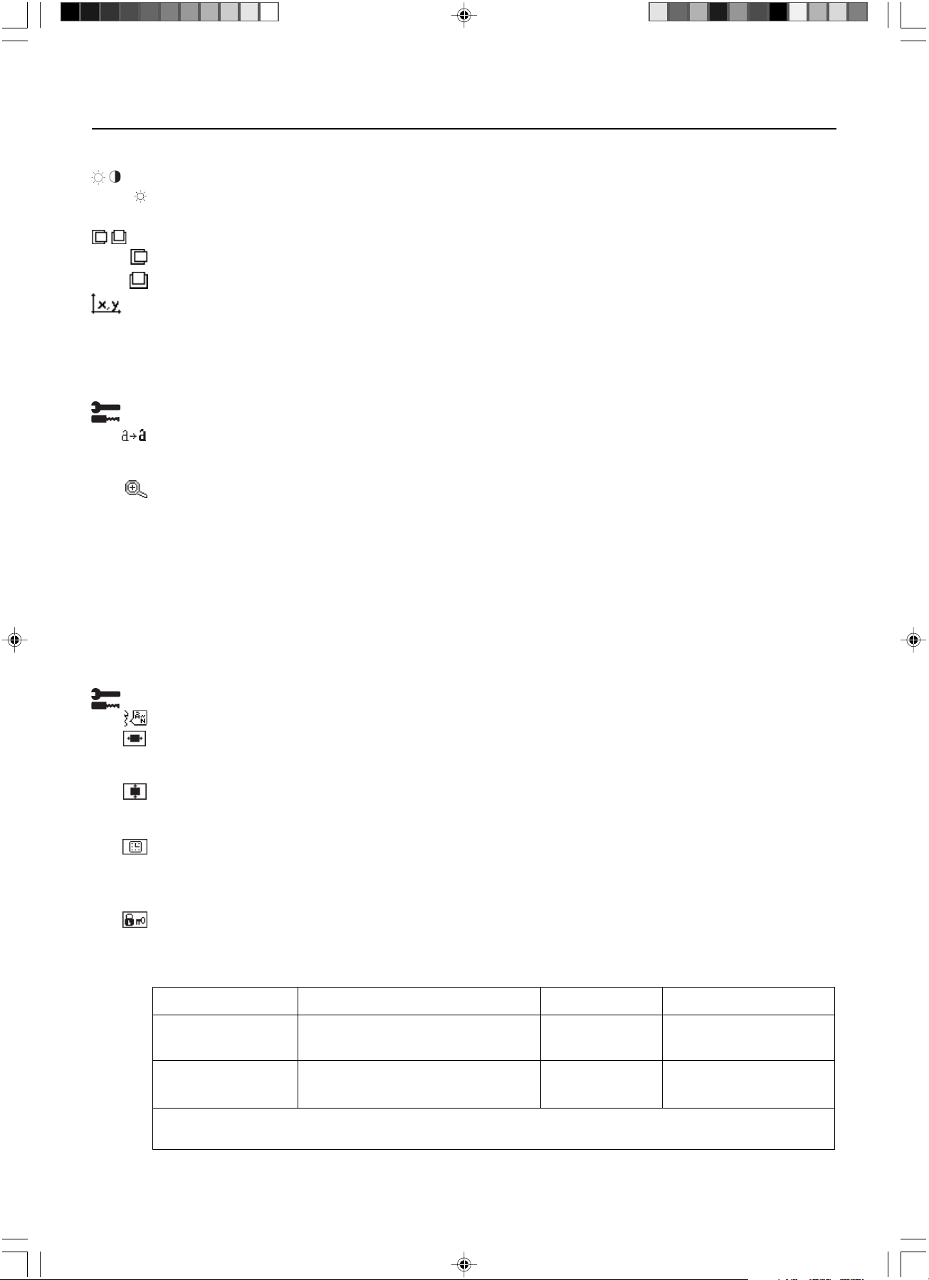
Français.6
Affichage à l’écran (OSD)
Luminosité
LUMINOSITÉ : Règle la luminosité globale de l’image et du fond de l’écran. Durant le règlage de la LUMINOSITE,
la valeur numérique clignote.
Contrôle de position (sauf mode de compression de pixel / 10 bits)
GAUCHE/DROITE : Contrôle la position horizontale de l’image dans la zone d’affichage.
BAS/HAUT : Contrôle la position verticale de l’image dans la zone d’affichage.
Sélection de point blanc
VALEUR PAR DÉFAUT : Sélection de point blanc en configuration usine d’origine (Clear Base ou Blue Base selon
le modèle)..
BLANC COPIE : Définition du point blanc par calibrage de copie.
NATIVE : Point blanc natif préréglé de l’affichage. Le paramètre de luminosité maximale est disponible.
Outils 1
NETTETÉ : Cette fonction ajuste numériquement le moniteur en cas d’images brouillées. Si la configuration d’usine
ne suffit pas, l’image est réglable manuellement. Cette fonction est opérationnelle quand le paramètre
GRAYSCALE BIT est réglé sur 8 bits.
MODE ÉTENDU : Règle la méthode de zoom.
PLEIN : La taille de l’image est agrandie à 1536 x 2048 quelle que soit la résolution.
ASPECT : L’image est agrandie sans modification des proportions.
ARRÊT : L’image n’est pas agrandie.
PERSONNALISE (résolution 1536 x 2048 uniquement) : Zoom sur centre fixe. Sélectionnez l’un des neuf taux
d’expansion. Avec ce mode la résolution peut être basse et laisser des zones blanches. Ce mode est destiné à être
utilisé avec des cartes graphiques spéciales.
BIT NIVEAU DES GRIS : Sélectionnez les bits de nuance de gris GRAYSCALE BIT (8 ou 10 bits) de la carte
graphique.
8 bits – 256 nuances de gris
10 bits – 1024 nuances de gris
Outils 2
LANGUE : Les menus des commandes OSD sont disponibles en sept langues.
OSD GAUCHE/DROITE : Vous pouvez choisir l’emplacement d’affichage, sur la moitié supérieure de l’écran, de
la fenêtre de commandes OSD. En choisissant Position de l’OSD, vous pouvez régler manuellement la position du
menu de commandes OSD : gauche ou droite.
OSD BAS/HAUT : Vous pouvez choisir l’emplacement d’affichage, sur la moitié supérieure de l’écran, de la
fenêtre de commandes OSD. En choisissant Position de l’OSD, vous pouvez régler manuellement la position du
menu de commandes OSD : en bas ou en haut.
EXTINCTION DE L’OSD : Le menu des commandes OSD restera à l’écran aussi longtemps qu’il sera utilisé. Dans
le sous-menu Extinction OSD, vous pouvez choisir la durée d’attente du moniteur entre la dernière pression de
touche et l’extinction du menu des commandes OSD. Les choix prédéfinis sont situés entre 10 et 120 secondes,
par pas de 5 secondes.
VERROUILLAGE OSD : Cette commande bloque totalement l’accès à tout ou partie des fonctions de commande
OSD. Toute tentative d’activation des commandes OSD, lorsque ce dernier est en mode verrouillé, provoque
l’apparition d’un écran informant que les commandes OSD sont verrouillées. Il existe trois types de
VERROUILLAGE OSD :
GRAY
BIT
MODE La touche ouvre l’avertissement LUMINOSITE EN MODE VERROUILLE
VERROUILLAGE OSD SELECT, > Non Oui
sans commande
VERROUILLAGE OSD SELECT, –, < Oui Oui
avec LUMINOSITÉ
Pour l’option CUSTOM LOCK OUT (VERROUILLAGE PERSONNALISÉ), veuillez vous reporter à la section OSD Avancé.
03_MD21GS3MPINSTALL_FR.P65 08/08/2005, 12:016
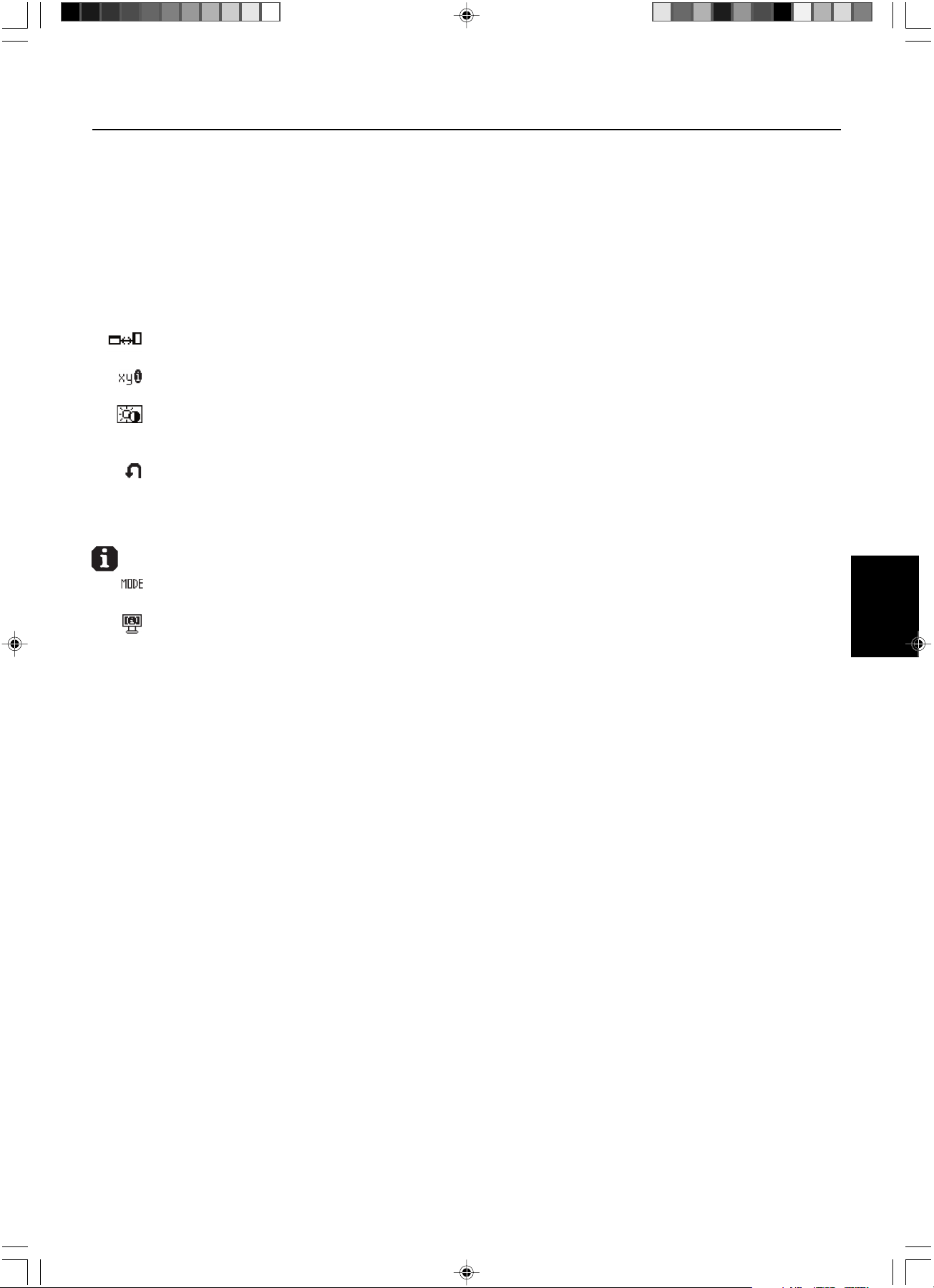
Français.7
Français
Affichage à l’écran (OSD) – suite
VERROUILLAGE OSD sans commande : Pour activer la fonction de verrouillage OSD, appuyez sur le bouton
SÉLECTION, puis sur la touche « > » et maintenez-les simultanément enfoncés. Pour désactiver le verrouillage
OSD, appuyez sur le bouton SÉLECTION, puis sur la touche « > » et maintenez-les simultanément enfoncés
pendant que le menu OSD est affiché. Aucune commande ne peut être réglée en mode verrouillé.
VERROUILLAGE OSD avec commande LUMINOSITE : Pour activer la fonction de verrouillage OSD, appuyez sur
le bouton SÉLECTION, puis sur la touche « - » et « < » et maintenez-les simultanément enfoncés. Pour désactiver
le verrouillage OSD, appuyez sur le bouton SÉLECTION, puis sur la touche « - » et « < » et maintenez-les
simultanément enfoncés pendant que le menu OSD est affiché. La commande LUMINOSITE ne peut être réglée
qu’en mode verrouillé.
ROTATION DE L’OSD : Pour faire passer OSD du mode paysage en mode portrait et inversement.
Utilisez la touche + ou – pour changer l’orientation de l’OSD et de l’aide sur commande affichées.
NOTIFICAT. RÉSOLUTION : La résolution optimale est de 1536 x 2048. Le choix de l’option MARCHE provoque
l’affichage après 30 secondes d’un message vous avertissant que la résolution n’est pas à 1536 x 2048.
TOUCHE DE RACCOURCI : Vous pouvez régler directement la luminosité. Lorsque cette fonction est sur ON, vous
pouvez régler la luminosité avec <, >, + ou -, tandis que le menu OSD est désactivé. Le menu OSD par défaut est
accessible à l’aide du bouton EXIT.
PRÉRÉGLAGE USINE : Cette option vous permet de redéfinir tous les paramètres des commandes OSD
(LUMINOSITÉ, CONTROLE DE POSITION, SELECTION DE POINT BLANC, NETTETÉ, MODE ÉTENDU, GAUCHE/
DROITE OSD, BAS/HAUT OSD, DÉSACTIVATION OSD, MODE AFFICHAGE) tels qu’ils étaient à leur sortie
d’usine. Les paramètres individuels peuvent être réinitialisés en mettant la commande concernée en surbrillance et
en appuyant sur le bouton RESET.
Informations
MODE D’AFFICHAGE : Fournit des informations sur la résolution d’affichage actuelle ainsi que des données
techniques comprenant le préréglage de résolution utilisé et les fréquences horizontale et verticale.
INFOS MONITEUR : Indique le nom du modèle et les numéros de série de votre moniteur.
Avertissements OSD
Pour effacer l’avertissement affiché, appuyez sur le bouton EXIT.
PAS DE SIGNAL : Cette fonction vous avertit lorsque aucun signal horizontal ou vertical de synchronisation n’est
présent. Après la mise sous tension ou en cas de changement du signal d’entrée, la fenêtre Pas de signal
s’affiche.
NOTIFICAT. RÉSOLUTION : Cette fonction vous avertit de l’utilisation en résolution optimisée. Après la mise sous
tension, ou en cas de changement du signal d’entrée, ou si le signal vidéo ne possède pas la résolution
appropriée, la fenêtre Notification de résolution s’affiche. Cette fonction peut être désactivée dans le menu
OUTILS 2.
HORS LIMITE : Cette fonction affiche un conseil sur la résolution optimisée et le taux de rafraîchissement
recommandés. Après la mise sous tension ou en cas de modification du signal d’entrée ou encore si le signal
vidéo ne possède pas la résolution appropriée, le menu Hors limites s’affiche.
VERROUILLAGE OSD : Cette fonction indique que la fonction OSD a été verrouillée par l’utilisateur. Eelle peut être
désactivée grâce au menu VERROUILLAGE PERSONNALISE.
AUTONOMIE DE LAMPE : L’avertissement OSD s’affiche à 1000/500/0 heures. L’affichage ne maintient pas les
niveaux de luminescence définis par l’utilisateur mais conserve le point blanc. Veuillez contacter votre fournisseur
si cet avertissement OSD s’affiche.
LUMINOSITÉ, AVERTISSEMENT : Cette fonction indique si le réglage de la LUMINOSITE ne peut pas être effectué.
03_MD21GS3MPINSTALL_FR.P65 08/08/2005, 12:017

Français.8
Affichage à l’écran avancé
L’OSD avancé ajoute d’autres commandes aux commandes OSD standard. Quand l’OSD est désactivé, appuyez sur les boutons
« RESET » et « EXIT » simultanément pour activer l’OSD avancé. REMARQUE : Ce menu occupe plus de place que le menu OSD
normal. Pour procéder à un réglage, vérifiez que l’élément qui vous intéresse est bien en surbrillance et appuyez sur SELECT.
Pour passer à un autre élément, appuyez successivement sur EXIT, puis sur < ou > pour mettre l’autre élément en surbrillance.
Élément1
Brightness Règle la luminosité globale de l’image et du fond de l’écran par sa valeur numérique. Appuyez sur + ou sur - pour
procéder à des réglages. Durant le règlage de la LUMINOSITE, la valeur numérique clignote.
Élément2
Cet élément n’est pas réglable.
Élément3
H. Position Contrôle la position horizontale de l’image dans l’affichage. Appuyez sur + ou sur - pour procéder à des réglages.
V. Position Contrôle la position verticale de l’image dans l’affichage. Appuyez sur + ou sur - pour procéder à des réglages.
Élément4
Gamma Selection Vous permet de sélectionner manuellement le niveau de luminosité des gris. Il y a cinq possibilités :
NO CORRECTION, DICOM, LOG LINEAR, CUSTOM et PROGRAMMABLE.
1. NO CORRECTION
2. DICOM : La fonction DICOM GSDF (fonction d’affichage standard des gris) est possible. DICOM LUT est calculé
en se basant sur les données de calibrage usine pour chaque écran individuellement.
3. LOG LINEAR : La luminescence change le log rythmiquement en réponse à un changement linéaire de gradation.
4. CUSTOM : La valeur gamma peut être sélectionnée dans une gamme comprise entre 0,5 et 4,0 par pas de 0,1.
5. PROGRAMMABLE : La luminosité des gris peut être changée avec le logiciel GammaComp MD.
Gamma Offset Règle le niveau de noir du paramètre de gamma. REMARQUE : Le paramètre DICOM n’est pas réglable.
Élément5
White Point Selection
DEFAULT : Sélection de point blanc en configuration usine d’origine (Clear Base ou Blue Base selon le modèle)..
COPIED WHITE : Définition du point blanc par calibrage de copie.
NATIVE : Point blanc natif préréglé de l’affichage. Le paramètre de luminosité maximale est disponible.
Élément6
Self Test Mode Affiche un écran complètement blanc. Utilisé pour la correspondance ou l’affichage de copie du point blanc.
Lamp Lifetime Estime la durée de vie de la lampe. Cette autonomie dépend du paramètre d’affichage de la luminescence.
Temperature Affiche la température interne de l’écran et celle du capteur de rétro-éclairage interne.
BRIGHTNESS Affiche les niveaux de luminescence cible et actuel en cd/m
2
.
INFO
Élément7
Sharpness Cette fonction ajuste numériquement l’affichage en cas d’images brouillées. Si la configuration d’usine ne suffit
pas, l’image est réglable manuellement. Cette fonction est opérationnelle quand le paramètre GRAYSCALE BIT
est sur 8 bits.
Expansion Mode
Règle la méthode de zoom.
FULL : La taille de l’image est agrandie à 1536 x 2048, quelle que soit la résolution.
ASPECT : L’image est agrandie sans modification des proportions.
OFF : L’image n’est pas agrandie.
CUSTOM (1536 x 2048 uniquement) : Zoom sur centre fixe. Sélectionnez l’un des neuf taux d’expansion. Avec ce
mode la résolution peut être basse et laisser des zones blanches. Ce mode est destiné à être utilisé avec des cartes
graphiques spéciales.
Grayscale Bit Sélectionnez la valeur GRAYSCALE BIT, 8 ou 10 bits.
Language Les menus des commandes OSD sont disponibles en sept langues. Appuyez sur + ou sur - pour opérer une sélection.
OSD Left/Right Vous pouvez choisir l’emplacement d’affichage, sur la moitié supérieure de l’écran, de la fenêtre de commandes
OSD. En choisissant Position de l’OSD, vous pouvez régler manuellement la position du menu de commandes OSD :
gauche ou droite.
OSD Down/UP Vous pouvez choisir l’emplacement d’affichage, sur la moitié supérieure de l’écran, de la fenêtre de commandes
OSD. En choisissant Position de l’OSD, vous pouvez régler manuellement la position du menu de commandes OSD :
en bas ou en haut.
OSD Turn Off Le menu des commandes OSD reste à l’écran aussi longtemps qu’il est utilisé. Dans le sous-menu de désactivation
OSD, vous pouvez sélectionner combien de temps le moniteur attend après la dernière utilisation d’un bouton pour
fermer le menu de commandes OSD. Les choix prédéfinis sont situés entre 10 et 120 secondes, par pas de
5 secondes.
03_MD21GS3MPINSTALL_FR.P65 08/08/2005, 12:018
Français.9
Français
Affichage à l’écran avancé – suite
OSD Lock Out Cette commande bloque totalement l’accès à toutes les fonctions de commande OSD. Quand vous tentez d’activer
l’OSD lorsque ce dernier est en mode verrouillé, cela provoque l’apparition d’un écran informant que les
commandes OSD sont verrouillées. Il existe trois types de VERROUILLAGE OSD :
OSD LOCK OUT sans commande : Pour activer la fonction de verrouillage OSD, appuyez sur le bouton SÉLECTION,
puis sur la touche « > » et maintenez-les simultanément enfoncés. Pour désactiver le verrouillage OSD, appuyez sur
le bouton SÉLECTION, puis sur la touche « > » et maintenez-les simultanément enfoncés pendant que le menu OSD
est affiché. Aucune commande ne peut être réglée en mode verrouillé.
OSD LOCK OUT avec commande LUMINOSITE : Pour activer la fonction Verrouillage OSD, appuyez sur SELECT,
puis les touches - et < en les maintenant simultanément enfoncées. Pour désactiver le verrouillage OSD, appuyez sur
le bouton SÉLECTION, puis sur les touches « - » et « < » et maintenez-les simultanément enfoncées pendant que le
menu OSD est affiché. La commande LUMINOSITE ne peut être réglée qu’en mode verrouillé.
PERSONNALISÉ : Appuyez sur RESET et EXIT pour ouvrir le menu PERSONNALISÉ. Sélectionnez ACTIVER ou
DÉSACTIVER pour les options LUMINOSITÉ ou AVERTISSEMENT (ERREUR RÉSOLUTION/VERROUILLAGE OSD).
OSD Rotation Pour faire passer OSD du mode Paysage en mode Portrait et inversement. Appuyez sur + ou sur - pour opérer une
sélection.
Resolution Notifier La résolution optimale est de 1536 x 2048. Le choix de l’option MARCHE provoque l’affichage après 30 secondes
d’un message vous avertissant que la résolution n’est pas à 1536 x 2048. Appuyez sur + ou sur - pour opérer une
sélection.
HOT KEY Vous pouvez régler directement la luminosité. Lorsque cette fonction est sur ON, vous pouvez régler la luminosité
avec <, >, + ou -, tandis que le menu OSD est désactivé. Le menu OSD par défaut est accessible à l’aide du bouton
EXIT.
LED Brightness Commande la luminosité du témoin LED de l’écran, « OFF » (ARRET), « MID » (MOYEN) et « MAX » (MAXIMUM).
Factory Preset Cette option vous permet de redéfinir tous les paramètres des commandes OSD (LUMINOSITÉ, Position H, Position V,
Sélection gamma, Correction gamma, SELECTION DE POINT BLANC, NETTETÉ, MODE ÉTENDU, GAUCHE/DROITE
OSD, BAS/HAUT OSD, DÉSACTIVATION OSD, AFFICHAGE AUTO, MODE AFFICHAGE) tels qu’ils étaient à leur
sortie d’usine. Les paramètres individuels peuvent être réinitialisés en mettant la commande concernée en surbrillance
et en appuyant sur le bouton RESET.
Élément8
Cet élément n’est pas réglable.
Élément9
Display Mode Fournit des informations sur la résolution d’affichage actuelle ainsi que des données techniques comprenant le
préréglage de temps utilisé et les fréquences horizontale et verticale. Augmente ou diminue la résolution actuelle.
Appuyez sur SELECT pour déplacer le mode de réglage et appuyez sur + ou sur – pour régler la résolution
horizontale et verticale.
Monitor Info. Indique le nom du modèle et les numéros de série de votre moniteur.
MODE La touche ouvre l’avertissement LUMINOSITE en mode VERROUILLAGE
OSD LOCK OUT SELECT, > Non Oui
sans commande
OSD LOCK OUT SELECT, –, < Oui
avec LUMINOSITÉ
VERROUILLAGE Processus d’activation en 7 étapes : Sélectionnable Sélectionnable
PERSONNALISÉ 1. Appuyez sur RESET et EXIT pour ouvrir le menu
OSD avancé
2. Appuyez sur < pour atteindre l’élément 7
3. Mettez en surbrillance la fonction
VERROUILLAGE OSD
4. Appuyez sur RESET et EXIT
5. ACTIVER ou DÉSACTIVER : LUMINOSITÉ,
AVERTISSEMENT
6. Appuyez sur SELECT pour passer en mode
VERROUILLAGE OSD
7. Appuyez sur EXIT pour quitter l’OSD
Pour désactiver :
1. Appuyez sur RESET et EXIT pour afficher
l’aide sur commandes
2. Appuyez sur SELECT, SELECT, <, >, <, >, EXIT
03_MD21GS3MPINSTALL_FR.P65 08/08/2005, 12:019
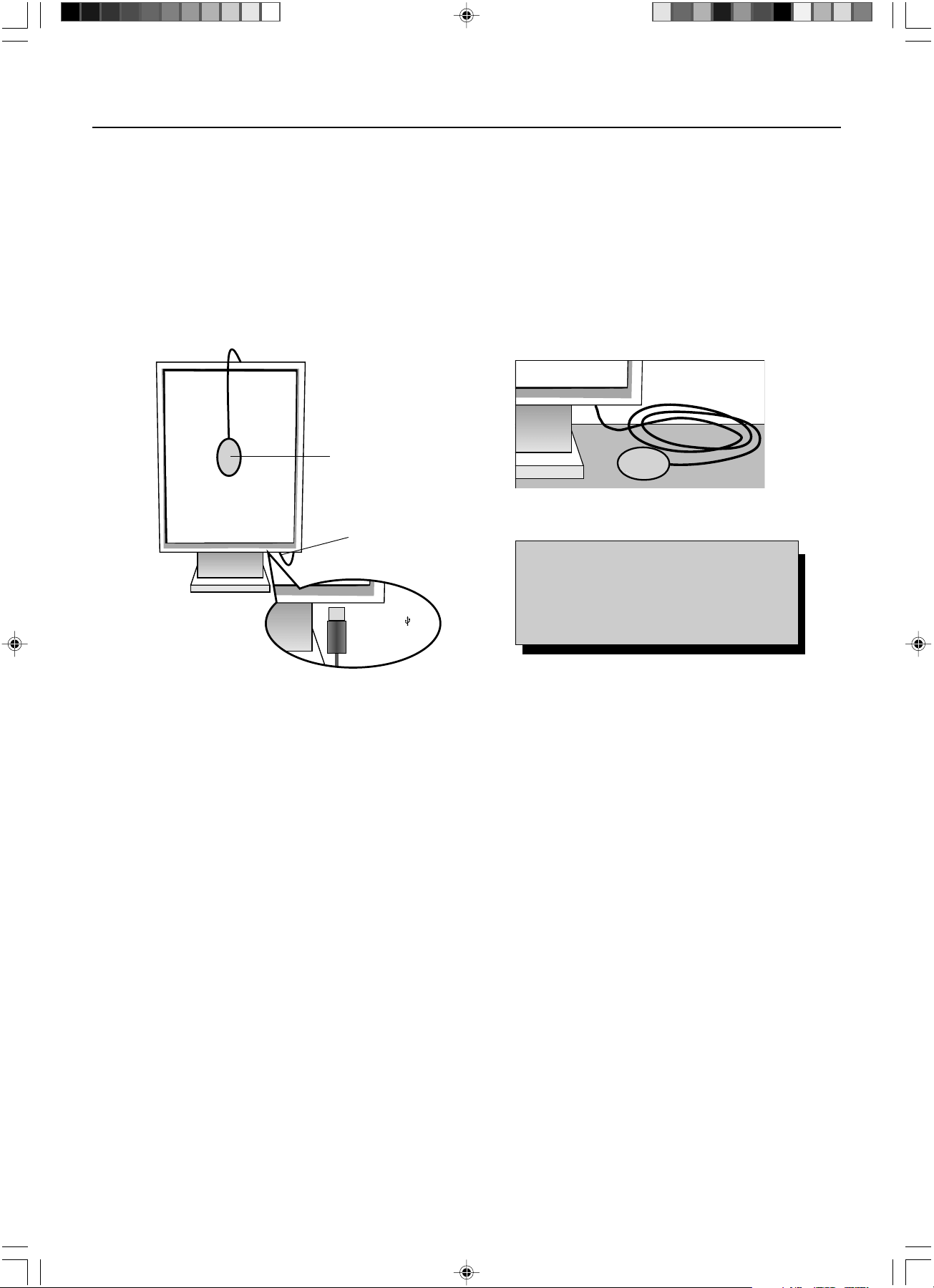
Français.10
Utilisez le logiciel de contrôle qualité GammaComp MD pour la gestion de l’historique (Test de cohérence). Avant que puisse s’effectuer
un affichage auto efficace, le moniteur doit se réchauffer pendant au moins 30 minutes. Si le capteur USB est branché avant que soit
atteint le degré de réchauffement adapté, un avertissement s’affiche à l’écran (Figure S.3). REMARQUE :
Un affichage autonome ne
peut s’effectuer qu’avec le capteur d’affichage GretagMacbeth Eye-One
. Référez-vous à la configuration KEY MAP (Figure A) lors de la
modification de paramètres en cours d’affichage.
1. Branchez le capteur USB sur le port capteur (Figure S.1).
REMARQUE : Le port capteur est réservé à la connexion du capteur.
2. Le menu d’affichage s’ouvre automatiquement et l’initialisation du capteur est lancée. Après initialisation, le message relatif à la
mesure du point noir « DARK-MEASUREMENT » s’affiche. Si ce message n’apparaît pas, veuillez passer à l’étape 5.
3. Placez le capteur USB à plat sur une surface opaque non réfléchissante (par exemple un bureau ou un tapis de souris) pour mesurer
le niveau de noir appelé « DARK-MEASUREMENT » (Figure S.2). Appuyez sur SELECT.
4. Une fois la mesure « DARK-MEASUREMENT » prise (Figure S.4), appuyez sur SELECT pour continuer.
Si la mesure « DARK-MEASUREMENT » échoue (Figure S.5), redémarrez le processus d’affichage.
5. Utilisez les touches « + » ou « - » pour sélectionner « SELF » (AUTO) dans la sélection du « MODE » (Figure S.6). Appuyez sur
« < » ou « > » pour passer à la sélection suivante. Utilisez les touches « + » ou « - » pour sélectionner « DEFAULT » (PAR DEFAUT)
ou « COPIED WHITE » (BLANC COPIE) dans la sélection « WHITE » (BLANC) (Figure S.6). Appuyez sur « < » ou « > » pour
passer à la sélection suivante.
6. Sélectionnez l’option GAMMA : « NO CORRECTION » (AUCUNE CORRECTION), DICOM, « LOG LINEAR » (LOG LINEAIRE),
« PROGRAMMABLE » ou « CUSTOM » (PERSONNALISÉ) ou « SKIP » (PASSER) (Figure S.6).
REMARQUE : Si « CUSTOM » (PERSONNALISÉ) est sélectionné, la valeur de gamma est modifiable manuellement par pas de
0,1 à 0,5 – 4,0. Si « SKIP » (PASSER) est sélectionné, le réglage du GAMMA d’affichage est passé, ce qui réduit le
temps d’affichage.
7. En cours de processus, il est demandé de placer le capteur USB au centre de l’écran (Figure S.7). Inclinez le panneau d’écran
d’environ 5° en arrière et placez le capteur USB au centre du panneau d’écran (Figure S.1).
REMARQUE : Placez le capteur USB à plat contre l’écran LCD pour éviter une contamination par lumière extérieure.
Ne pressez SURTOUT PAS l’afficheur contre le panneau d’écran. Appuyez sur SELECT.
8. Réglez l’option de « LUMINANCE » (LUMINESCENCE) (cd/m
2
) (Figure S.8).
Affichage auto
Figure S.1
Port capteur
Figure S.2
Figure A
Capteur USB
l’îcone USB ( ) est
de l’autre côté
KEY MAP
< / > : modification de paramètre à paramètre
– / + : modification des paramètres sélectionnés
(soit SELF soit COPY)
SELECT : passé à l’étape d’affichage suivante
SORTIE : revient à l’étape d’affichage précédente
03_MD21GS3MPINSTALL_FR.P65 08/08/2005, 12:0110
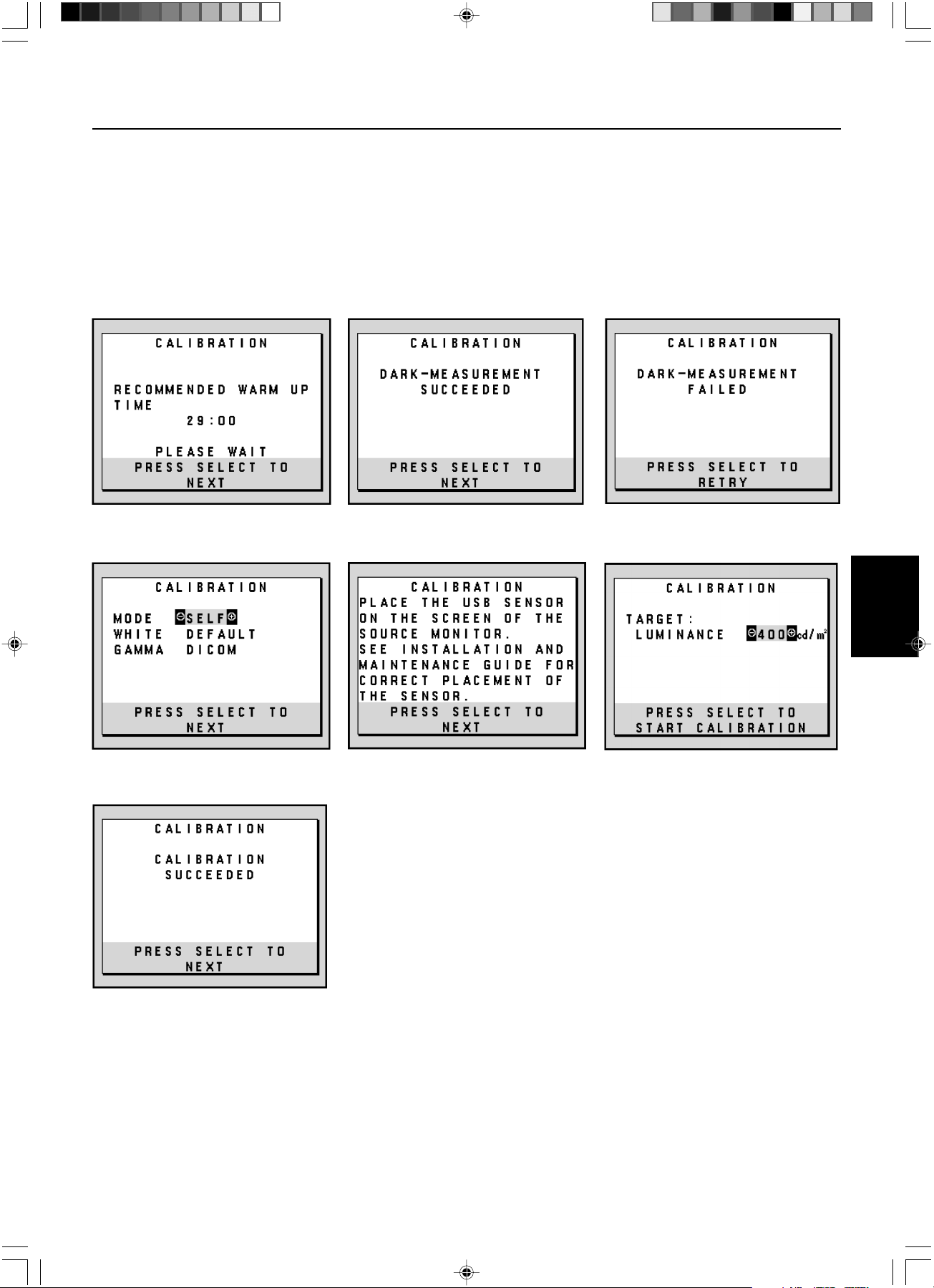
Français.11
Français
Affichage auto – suite
9. Appuyez sur SELECT pour lancer l’affichage. Un affichage autonome peut prendre plusieurs minutes selon les paramètres utilisateur.
10. Une fois affiché le message « CALIBRATION SUCCEEDED » (AFFICHAGE RÉUSSI) (Figure S.9), appuyez sur SELECT.
11. Pour sortir du mode affichage, appuyez sur EXIT.
Figure S.4 Figure S.5
Figure S.9
Figure S.3
Figure S.7 Figure S.8Figure S.6
03_MD21GS3MPINSTALL_FR.P65 08/08/2005, 12:0111
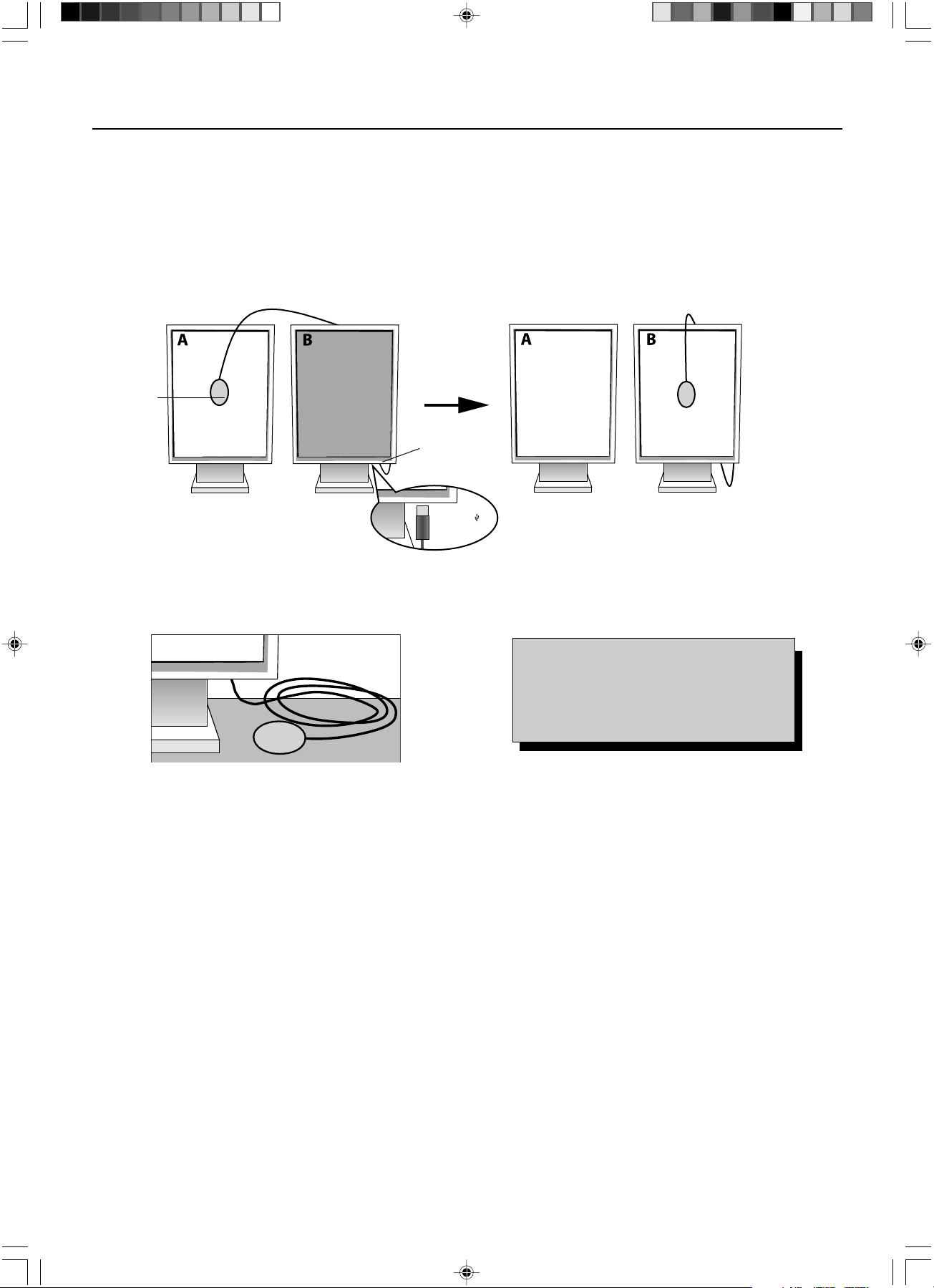
Français.12
Utilisez le logiciel de contrôle qualité GammaComp MD pour la gestion de l’historique (Test de cohérence). Avant que puisse s’effectuer
un affichage par copie efficace, le moniteur doit se réchauffer pendant au moins 30 minutes. Si le capteur USB est branché avant que
soit atteint le degré de réchauffement adapté, un avertissement s’affiche à l’écran (Figure C.3). REMARQUE :
Un affichage autonome ne
peut s’effectuer qu’avec le capteur d’affichage GretagMacbeth Eye-One
. Référez-vous à la configuration KEY MAP (Figure A) lors de la
modification de paramètres en cours d’affichage.
1. Branchez le capteur USB sur le port capteur (Figure C.1).
REMARQUE : Le port capteur est réservé à la connexion du capteur.
2. Le menu d’affichage s’ouvre automatiquement et l’initialisation du capteur USB est lancée. Après initialisation, le message relatif à
la mesure du point noir « DARK-MEASUREMENT » s’affiche. Si ce message n’apparaît pas, veuillez passer à l’étape 5.
3. Placez le capteur d’écran à plat sur une surface opaque non réfléchissante (par exemple un bureau ou un tapis de souris) pour
mesurer le niveau de noir (Figure C.3). Appuyez sur SELECT.
4. Une fois la mesure du point noir prise (Figure C.5), appuyez sur SELECT pour continuer. Si la mesure du point noir échoue
(Figure C.6), reprenez le processus d’affichage à partir de l’étape 1.
5. L’écran A doit être blanc, entrez dans le menu OSD avancé en appuyant sur « RESET » (REINITIALISER) et « EXIT » (QUITTER).
Utilisez les touches « < » ou « > » pour aller à l’élément 6 et sélectionnez « SELF-TEST MODE » (MODE TEST AUTO).
6. En utilisant « + » ou « – », sélectionnez « COPY » (COPIER) dans la sélection du MODE (Figure C.7). Sélectionnez « ON »
(MARCHE) ou « OFF » (ARRET) dans la sélection « SELF » (AUTO). Si « ON » (MARCHE) est sélectionné, le calibrage automatique
« SELF » s’exécute avec la calibrage « COPY » (COPIER).
7. Sélectionnez l’option GAMMA : « NO CORRECTION » (AUCUNE CORRECTION), « DICOM », « LOG LINEAR » (LOG LINEAIRE),
« PROGRAMMABLE » ou « CUSTOM » (PERSONNALISÉ). Veuillez sélectionner la même option GAMMA que pour l’écran A.
REMARQUE : Si « CUSTOM » (PERSONNALISÉ) est sélectionné, la valeur de gamma est modifiable manuellement par pas
de 0,1 à 0,5-4,0.
8. En cours de processus, il est demandé de placer le capteur USB au centre du panneau d’écran (Figure C.8).
Inclinez le panneau d’écran d’environ 5° en arrière et placez le capteur USB au centre du panneau d’écran (Figure C.1).
REMARQUE : Placez le capteur USB à plat contre l’écran pour éviter une contamination par lumière extérieure.
Ne pressez SURTOUT PAS l’afficheur contre le panneau d’écran. Appuyez sur SELECT.
Affichage par correspondance de point blanc/par copie
Ecran A – Moniteur SOURCE du point blanc à copier.
Ecran B – Moniteur CIBLE effectuant un affichage par copie.
Figure C.1
Figure C.2
Port capteur
Figure C.3 Figure A
Capteur
USB
l’îcone USB ( ) est
de l’autre côté
KEY MAP
< / > : modification de paramètre à paramètre
– / + : modification des paramètres sélectionnés
(soit SELF soit COPY)
SELECT : passé à l’étape d’affichage suivante
SORTIE : revient à l’étape d’affichage précédente
03_MD21GS3MPINSTALL_FR.P65 08/08/2005, 12:0112
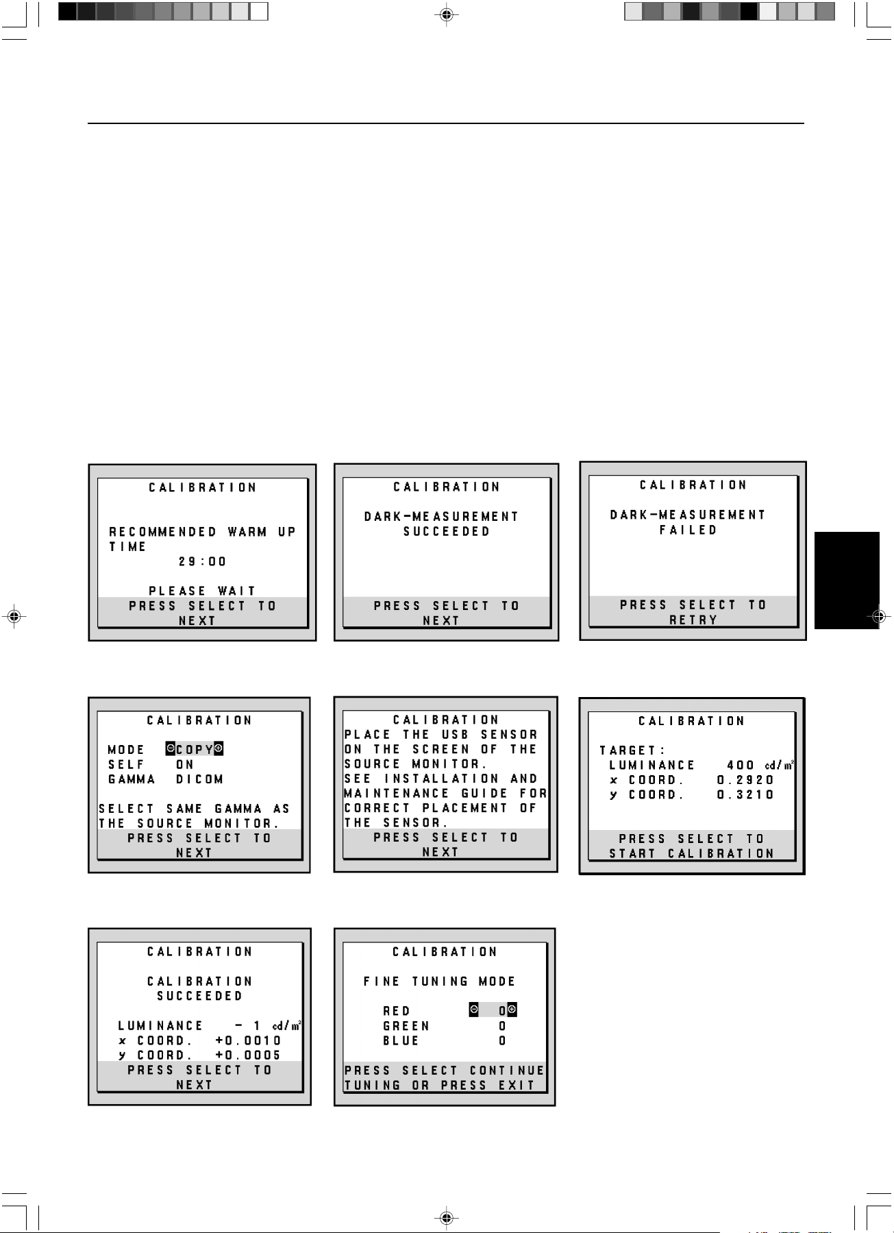
Français.13
Français
Affichage par correspondance de point blanc/par copie – suite
9. Appuyez sur SELECT dans l’écran B pour lancer la lecture des informations sur le point blanc dans l’écran A.
10. Une fois copiées les informations de l’écran A, la « LUMINANCE » (LUMINESCENCE) cible et les coordonnées chromatiques cibles
sont mémorisées et affichées dans l’OSD de l’écran B. La « TARGET VALUE » (VALEUR CIBLE) n’est pas réglable (Figure C.9).
11. Enlevez le capteur d’écran de USB source A et placez-le au centre de l’écran B (Figure C.2).
12. Appuyez sur SELECT pour lancer l’affichage par copie. Un affichage par copie peut prendre plusieurs minutes selon les paramètres
utilisateur.
13. Une fois l’affichage réussi, les points blancs des écrans A et B doivent correspondre. Une fois le « CALIBRATION SUCCEEDED »
(AFFICHAGE RÉUSSI) (Figure C.10) affiché, appuyez sur SELECT pour continuer et passer en MODE RÉGLAGE AFFINÉ.
14. Une fois affiché le message « FINE TUNING MODE » (MODE RÉGLAGE AFFINÉ) (Figure C.11), appuyez sur EXIT si l’affichage est
satisfaisant. Si l’affichage n’est pas satisfaisant, deux solutions sont possibles :
(A) Réglez manuellement le point blanc avec les touches + et -.
(B) Redémarrez l’affichage par copie automatique, appuyez sur SELECT et revenez à l’étape 3.
15. Pour sortir du mode réglage d’affichage, appuyez sur EXIT.
Figure C.5 Figure C.6
Figure C.10 Figure C.11
Figure C.4
Figure C.8 Figure C.9Figure C.7
03_MD21GS3MPINSTALL_FR.P65 08/08/2005, 12:0113
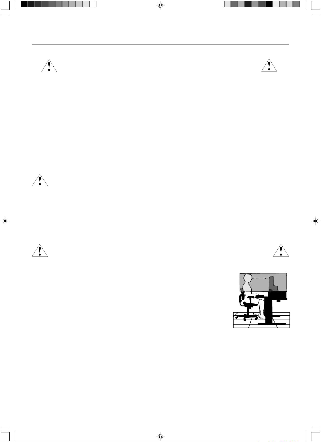
Français.14
Consignes de sécurité et d’entretien
POUR UN FONCTIONNEMENT OPTIMAL, VEUILLEZ NOTER CE QUI
SUIT POUR L’INSTALLATION ET L’UTILISATION DE L’ECRAN NEC :
• N’OUVREZ JAMAIS LE BOÎTIER DU MONITEUR. Aucune pièce interne ne peut être réparée par l’utilisateur et l’ouverture ou la dépose des capots peuvent vous
exposer à des risques d’électrocution ou autres. Confiez toutes les interventions de dépannage à un personnel technique qualifié.
• Ne renversez pas de liquides dans le boîtier et n’utilisez pas votre écran près d’une source d’eau.
• N’introduisez pas d’objets de quelque nature que ce soit dans les fentes du boîtier car ces objets pourraient toucher des endroits sous tension dangereuse, ce qui
peut provoquer des blessures, voire être fatal, ou peut occasionner une décharge électrique, un incendie ou une panne de l’appareil.
• Ne placez pas d’objets lourds sur le cordon d’alimentation. Un cordon endommagé peut occasionner une décharge électrique ou un incendie.
• Ne placez pas cet appareil sur un chariot, un support ou une table bancals ou instables, car en cas de chute du moniteur, des dommages graves sont à redouter.
• Ne placez aucun objet sur l’écran et ne l’utilisez pas en extérieur.
• L’intérieur du tube fluorescent situé dans l’écran contient du mercure. Conformez-vous aux lois ou à la réglementation de votre localité pour vous débarrasser de ce tube.
• Ne pliez pas le cordon d’alimentation.
• N’utilisez pas votre moniteur dans des endroits à hautes températures, humides, poussiéreux ou huileux.
• N’obstruez pas les aérations de l’écran.
Débranchez immédiatement le moniteur de la prise murale et confiez la réparation à du personnel qualifié dans les cas suivants :
• Si le cordon d’alimentation ou la prise sont endommagés.
• Si du liquide a été renversé ou si des objets sont tombés à l’intérieur de l’écran.
• Si l’écran a été exposé à la pluie ou à de l’eau.
• Si l’écran est tombé ou si le boîtier est endommagé.
• Si l’écran ne fonctionne pas normalement tout en étant utilisé conformément aux directives d’utilisation.
• Manipulez le moniteur avec précaution dans le cas de bris de verre.
• Si l’écran est cassé ou si la vitre est brisée, ne touchez pas le cristal liquide, et manipulez l’écran avec précaution.
• Prévoyez une aération suffisante autour de l’écran pour que la chaleur puisse se dissiper correctement. N’obstruez pas les ouvertures de
ventilation et ne placez pas l’écran près d’un radiateur ou d’une autre source de chaleur. Ne posez rien sur l’écran.
• La prise du cordon d’alimentation est le moyen principal par lequel on doit débrancher le système de l’alimentation électrique.
L’écran doit être installé à proximité d’une prise de courant facilement accessible.
• Manipulez le moniteur avec soin lors de son transport. Conservez l’emballage pour le transport.
Persistance de l’image
Nous vous informons que la technologie LCD peut provoquer un phénomène appelé « persistance de l’image ». La persistance de l’image se manifeste lorsqu’une
image résiduelle ou « fantôme » d’une image précédemment affichée reste visible sur l’écran. Contrairement aux moniteurs à tube cathodique, la persistance de
l’image sur les moniteurs LCD n’est pas permanente, mais l’on doit éviter d’afficher des images immobiles pendant une longue période de temps. Pour remédier à la
persistance de l’image, mettez le moniteur hors tension pendant une durée égale à celle de l’affichage de l’image précédemment affichée. Par exemple, si une image
est restée affichée sur l’écran pendant une heure et qu’il reste une image résiduelle, le moniteur doit être mis hors tension pendant une heure pour effacer l’image.
REMARQUE : Comme pour tous les équipements d’affichage personnels, nous recommandons d’afficher des images ou d’utiliser un économiseur d’écran animé(es) à
intervalles réguliers chaque fois que l’écran est en veille ou d’éteindre le moniteur lorsqu’il n’est pas utilisé.
UNE POSITION ET UN RÉGLAGE CORRECTS DU MONITEUR PEUVENT
RÉDUIRE LA FATIGUE DES YEUX, DES ÉPAULES ET DE LA NUQUE.
APPLIQUEZ CE QUI SUIT POUR POSITIONNER LE MONITEUR :
• Pour une performance optimale lors de calibrages automatiques et de copie, attendez que l’appareil se soit réchauffé 30 minutes.
• Réglez la hauteur de l’écran pour que le haut de l’écran soit au niveau ou légèrement au-dessous du niveau des yeux.
Vos yeux doivent pointer légèrement vers le bas pour regarder le milieu de l’écran.
• Positionnez l’écran au minimum à 40 cm et au maximum à 70 cm de vos yeux. 50,80 cm est la distance optimale.
• Reposez vos yeux régulièrement en regardant un objet situé à au moins 6 mètres. Clignez souvent des yeux.
• Placez l’écran à un angle de 90° par rapport aux fenêtres et autres sources de lumière pour réduire au maximum les reflets
et l’éblouissement. Réglez l’inclinaison du moniteur pour que l’éclairage du plafond ne se reflète pas sur l’écran.
• Nettoyez la surface de l’écran avec un chiffon sans peluches et non abrasif. Si ce n’est pas suffisant, essuyez avec un
chiffon imprégné d’eau, d’éthanol ou d’alcool isopropylique. N’utilisez pas de produit d’entretien ou de nettoyant pour
vitres (par exemple, acide, alcali ou acétone).
• Réglez les commandes de luminosité et de contraste de l’écran pour améliorer la lisibilité.
• Placez directement devant vous ce que vous regardez le plus souvent (l’écran ou les documents de référence) pour
minimiser les mouvements de la tête lorsque vous tapez.
•Évitez d’afficher des motifs fixes sur l’écran pendant de longues périodes pour éviter la rémanence (persistance de l’image).
Ergonomie
Pour obtenir l’ergonomie maximale possible, nous recommandons ce qui suit :
• Utilisez les commandes de taille et de position préprogrammées avec des signaux standard.
• Utilisez des signaux non entrelacés avec une fréquence de rafraîchissement vertical de 60 Hz.
Nettoyage de l’écran à cristaux liquides (LCD)
• Passez délicatement un chiffon doux pour enlever la poussière ou toute impureté de l’écran LCD.
• Ne frottez pas l’écran LCD avec une matière rugueuse.
• Ne posez aucun objet sur l’écran LCD.
• N’utilisez pas de nettoyant à base d’alcool sous peine d’endommager ou de décolorer la surface LCD.
Nettoyage du boîtier
• Débranchez le système d’alimentation électrique.
• Essuyez délicatement le boîtier avec un chiffon doux.
• Pour nettoyer le boîtier, imbiber le chiffon avec un détergent neutre et de l’eau, essuyez le boîtier et séchez avec un chiffon sec.
REMARQUE : La surface du boîtier contient de nombreuses matières plastiques. N’UTILISEZ PAS de benzène, diluant, détergent alcalin, détergent à base d’alcool,
nettoyant pour vitres, cire, vernis, lessive ou insecticide. Ne posez pas de matières en caoutchouc ou en vinyle sur le boîtier pendant de longues périodes. Ces
types de liquides et de tissus peuvent abîmer, craqueler ou écailler la peinture.
Conseils d’utilisation
ATTENTION
03_MD21GS3MPINSTALL_FR.P65 08/08/2005, 12:0114
Français.15
Français
Spécifications
Caractéristiques du moniteur Moniteur MD21GS-3MP Remarques
Module LCD Diagonale : 54 cm/21,3 pouces Matrice active ; transistor à couche mince
Dimensions de l’image affichable : 54 cm/21,3 pouces (TFT) liquide Ecran à cristaux liquide (LCD) ;
Résolution native (en pixels) : 1536 x 2048 (Portrait) pas de 0,2115mm ; 400 cd/m
2
luminance
2048 x 1536 (Paysage) de blanc calibrée; Ratio de contraste 700:1,
typique.
Signal d’entrée vidéo : Entrée numérique : DVI Horloge Vidéo à 162Mhz Max
Tons des gris 10 bits : 1024 (10 bits) ombres de gris Lorsque utilisé avec un 10 bits
une palette de 3061 (11,5 bits) recommandé carte graphique
8 bits : 256 (10 bits) ombres de gris Lorsque utilisé avec un 8 bits
une palette de 3061 (11,5 bits) recommandé carte graphique
Plage de Horizontale : 31,5 kHz à 96,0 kHz Automatiquement
synchronisation Verticale : 30 Hz, 50 Hz à 85 Hz Automatiquement
Angle de Gauche/Droite : ±88° (CR > 10)
visualisation Haut/Bas : ±88° (CR > 10)
Temps de formation de l'image 35 ms (Typ.)
Zone d’affichage Portrait : Horiz. : 325 mm/12,8 pouces
active Vert. : 433 mm/17,1 pouces
Paysage : Horiz. : 433 mm/17,1 pouces
Vert. : 325 mm/12,8 pouces
Alimentation 100-240V CA ~ 50/60Hz
Consommation de 0,7 à 0,35 A
Dimensions Portrait : 358,7 mm (Largeur) x 514 - 560 mm (Hauteur) x 200 mm (Profondeur)
14,1 pouces (Largeur) x 20,2 - 22,0 pouces (Hauteur) x 7,9 pouces (Profondeur)
Paysage : 467 mm (Largeur) x 460 - 506 mm (Hauteur) x 200 mm (Profondeur)
18,4 pouces (Largeur) x 18,1 - 19,9 pouces (Hauteur) x 7,9 pouces (Profondeur)
Réglage de la hauteur : 46 mm/1,8 pouces
Poids 11,7 kg (25,8 livres)
Conditions de l’environnement
Température de fonctionnement : de 5°C à 40°C/de 41°F à 104°C
Humidité : de 30% à 80% (sans condensation)
Altitude : de 0 à 10.000 Pieds/de 0 à 3.048 m
Température de stockage (emballé) : de -20°C à 60°C/de -4°F à 140°F
Humidité (emballé) : de 10% à 85% (sans condensation)
Pieds (emballé) : de 0 à 40.000 Pieds/de 0 à 12.192 m
Classification UL
Selon le type de protection contre les décharges électriques : CLASS I
Selon le degré de protection contre les décharges électriques : aucune connexion « Patient »
Selon le degré de protection contre les entrées d’eau, telles que définies dans la version actuelle de IEC529 : aucune protection
Selon la méthode de stérilisation ou de désinfection recommandée par le fabricant : non spécifiée
Selon le degré de sécurité du dispositif en présence de produits INFLAMMABLES MELANGES A L’AIR, L’OXYGENE OU D’OXYDE
NITREUX: Non approprié
Selon le mode de fonctionnement : fonctionnement en continu
03_MD21GS3MPINSTALL_FR.P65 08/08/2005, 12:0115

Français.16
DVI-D : Le sous-ensemble tout numérique de DVI validé par le groupe de travail sur l’affichage numérique (DDWG) pour
les connexions numériques entre ordinateurs et écrans. L’analogique n’est pas pris en charge par les connecteurs DVI-D qui
sont des connecteurs purement numériques. Il s’agit d’une connexion purement numérique basée sur DVI ; un adaptateur
simple suffit donc à assurer la compatibilité entre les connecteurs DVI-D et d’autres connecteurs numériques eux aussi
basés sur la norme DVI tels les connecteurs DFP et P&D.
P&D (Plug & Display) : Le standard VESA pour les interfaces avec les écrans plats. Plus robuste que DFP car elle permet
d’autres options (USB, vidéo analogique et IEEE 1394-995) à partir d’un connecteur de signal. Le comité VESA a reconnu
que DFP constitue un sous-ensemble de la norme P&D. Connecteur basé sur DVI (pour les broches d’entrée numérique),
P&D ne requiert qu’un simple adaptateur pour assurer la compatibilité entre P&D et les autres connecteurs numériques
basés sur DVI tels DVI et DFP.
Support tournant : Permet aux utilisateurs de choisir l’orientation d’écran la plus appropriée à leur application, Paysage
pour les documents larges ou Portrait pour afficher une page dans son intégralité à l’écran.
Encombrement réduit : Constitue la solution idéale pour les environnements nécessitant une image de haute qualité, mais
dans des conditions limitées d’espace et de poids. L’encombrement réduit et le faible poids de l’écran permettent de le
déplacer et de le transporter rapidement d’un endroit à un autre.
Commandes OSD (On-Screen Display - Affichage à l’écran) : Les commandes OSD avancées vous permettent de régler
rapidement et facilement tous les éléments de votre image d’écran par des menus à l’écran faciles d’utilisation et incluent
un verrouillage OSD complet.
Fonctions ErgoDesign : Concepts ergonomiques pour améliorer l’environnement de travail, protéger la santé de l’utilisateur
et économiser de l’argent. On peut citer comme exemple les commandes OSD pour le réglage rapide et facile de l’image,
le socle inclinable pour un meilleur angle de visualisation, l’encombrement réduit et la conformité aux directives MPRII pour
réduire les émissions.
Écran antireflets et basse radiation : Un écran antireflets basse radiation réduit les reflets et les radiations ambiantes.
Le niveau de perception de NOIR de l’écran est amélioré pour obtenir une image plus claire.
Technologie à fréquences multiples : Règle automatiquement l’écran à la fréquence de la carte graphique, affichant ainsi
la résolution requise.
Capacité FullScan (balayage complet) : Permet d’utiliser la totalité de la surface de l’écran dans la plupart des résolutions,
augmentant ainsi de façon significative la taille de l’image.
Technologie à large angle de visualisation : Permet à l’utilisateur de regarder l’écran sous n’importe quel angle
(176 degrés) et dans n’importe quelle orientation (portrait ou paysage). Offre un angle de visualisation complet de 176°,
que ce soit vers le haut, le bas, la gauche ou la droite.
Interface de montage à la norme VESA : Permet aux utilisateurs de fixer leur écran sur tout support ou bras de montage au
standard VESA. Permet de monter l’écran sur un mur ou sur un bras en utilisant tout dispositif tiers compatible.
Système de contre-éclairage X-Light : Au moyen d’un capteur interne, il permet de maintenir une luminosité consistante et
les niveaux de point blanc sur une longue période, rendant possible une excellente qualité de diagnostic. Le système
permet également l’affichage multiple du point blanc en utilisant pour la correspondance un puck de calibrage (vendu
séparément), qui contribue à une réduction des coûts et une augmentation de l’efficacité.
Caractéristiques
03_MD21GS3MPINSTALL_FR.P65 08/08/2005, 12:0116

Français.17
Français
Résolution des problèmes
Pas d’image
• Le câble vidéo doit être connecté à fond à la carte graphique et à l’ordinateur.
• La carte graphique doit être insérée à fond dans son logement.
• Vérifiez que l’interrupteur d’allumage est bien en position MARCHE.
• L’interrupteur d’alimentation doit être en position MARCHE (ON).
• Vérifiez qu’un mode d’affichage autorisé a bien été sélectionné pour la carte graphique ou le système utilisé.
(Veuillez consulter le manuel de votre carte graphique ou de votre système pour modifier le mode graphique.)
• Vérifiez la compatibilité et les paramètres recommandés de votre moniteur et de votre carte graphique.
• Vérifiez que le connecteur du câble de signal vidéo ne comporte aucune broche tordue ou enfoncée.
Le bouton d’alimentation ne répond pas
• Débranchez le cordon d’alimentation du moniteur de la prise murale CA pour éteindre et réinitialiser le moniteur.
• Vérifiez l’interrupteur d’alimentation en haut de l’écran (portrait) ou sur le côté (paysage).
Persistance de l’image
• Nous vous informons que la technologie LCD peut provoquer un phénomène appelé « persistance de l’image ». La persistance de
l’image se manifeste lorsqu’une image résiduelle ou « fantôme » d’une image précédemment affichée reste visible sur l’écran.
Contrairement aux moniteurs à tube cathodique, la persistance de l’image sur les moniteurs LCD n’est pas permanente, mais l’on
doit éviter d’afficher des images immobiles pendant une longue période de temps. Pour remédier à la persistance de l’image,
mettez le moniteur hors tension pendant une durée égale à celle de l’affichage de l’image précédemment affichée. Par exemple, si
une image est restée affichée sur l’écran pendant une heure et qu’il reste une image résiduelle, le moniteur doit être mis hors tension
pendant une heure pour effacer l’image.
REMARQUE : Comme pour tous les équipements d’affichage personnels, nous recommandons d’utiliser un économiseur d’écran
animé à intervalles réguliers chaque fois que l’écran est en veille ou d’éteindre le moniteur lorsqu’il n’est pas utilisé.
Le message HORS LIMITE est affiché (l’écran est vide ou n’affiche que des images indistinctes)
• L’image s’affiche grossièrement (des pixels manquent) et l’avertissement OSD « HORS GAMME » s’affiche pour indiquer que le
minutage des signaux ou la résolution sont trop élevés. Choisissez un mode pris en charge.
• L’avertissement OSD HORS LIMITES s’affiche sur un écran vide : La fréquence du signal est hors limites. Choisissez un mode pris en
charge.
L’image défile, est floue ou moirée
• Vérifiez que le câble vidéo est correctement connecté à l’ordinateur.
• Vérifiez la compatibilité et les paramètres recommandés de votre moniteur et de votre carte graphique.
• Si votre texte est altéré, passez en mode vidéo non entrelacé et utilisez un taux de rafraîchissement de 60 Hz.
L’image n’est pas à la bonne taille
• Vérifiez qu’un mode d’affichage autorisé a bien été sélectionné pour la carte graphique ou le système utilisé.
(Veuillez consulter le manuel de votre carte graphique ou de votre système pour modifier le mode graphique.)
• Vérifiez le MODE ÉTENDU de l’OSD.
Pas de vidéo
• Si aucune vidéo n’apparaît à l’écran, éteignez et rallumez l’écran.
• Assurez-vous que l’ordinateur n’est pas en mode d’économie d’énergie (actionnez le clavier ou bougez la souris).
Pas d’inclinaison
• Faites tourner l’écran à 90° dans le sens des aiguilles d’une montre jusqu’à ce que vous entendiez un déclic.
• Reportez-vous à la section Réglage et montage du moniteur pour vous assurer que l’installation du support est correcte.
PAS D’OSD
• Référez-vous à la fonction VERROUILLAGE OSD dans la section OSD avancé de ce manuel.
03_MD21GS3MPINSTALL_FR.P65 08/08/2005, 12:0117
Français.18
Références
Amérique du Nord et Canada
Service et support clientèle pour moniteur NEC
Service clientèle et support technique :
(800) 632-4662
Fax : (801) 907-3805
Pièces et accessoires/Macintosh
Adaptateur de câble : (800) 632-4662
Informations sur la garantie : www.necdisplay.com
Support technique en ligne www.necdisplay.com
Informations achats et produits
Ligne d’information achats : (888) 632-6487
Clientèle canadienne : (866) 771-0266, Ext#: 4037
Achats administration : (800) 284-6320
E-mail achats administration : gov@necdisplay.com
Ressources électroniques
Sur Internet : www.necdisplay.com
Enregistrement de produit : www.necdisplay.com
Pilotes et téléchargements www.necdisplay.com
Europe
Adresse
NEC Display Solutions Europe GmbH Téléphone : +49(0)89 99699 - 0
Landshuter Allee 12 -14
D-80637 München
Ressources en ligne
Sur Internet : www.medical.nec-display-solutions.com
03_MD21GS3MPINSTALL_FR.P65 08/08/2005, 12:0118
Français.19
Français
DÉCLARATION DE CONFORMITÉ
Pour les Etats-Unis
Cet appareil est conforme à la partie 15 du règlement FCC. Le fonctionnement est soumis aux deux conditions suivantes. (1) Cet appareil ne
peut pas provoquer d’interférence nuisible, et (2) cet appareil doit accepter toute interférence reçue y compris du type pouvant créer un
fonctionnement indésirable.
Type de produit : Moniteur pour ordinateur
Classification du matériel : périphérique de classe B
Modèle :
MD21GS-3MP-CB/MD21GS-3MP-BB
Par le présent document, nous déclarons que l’équipement indiqué ci-dessus
est conforme aux normes techniques décrites dans les règlements de la FCC.
Informations de la FCC
1.Utilisez les câbles spécifiés joints avec l’écran à nuances de gris MD21GS-3MP pour ne pas provoquer d’interférences avec la
réception radio et télévision.
(A) Veuillez utiliser le cordon d’alimentation fourni ou un équivalent pour assurer la conformité FCC.
(B) Veuillez utiliser le câble de signal vidéo blindé fourni.
L’utilisation d’autres types de câbles et adaptateurs peut provoquer des interférences avec la réception radio et télévision.
2.Cet équipement a été testé et déclaré conforme aux normes relatives au matériel informatique de la classe B, définies dans l’Article
15 des règlements de la FCC. Ces normes sont destinées à assurer une protection suffisante contre les interférences nuisibles dans une
installation résidentielle. Cet équipement génère et utilise des fréquences radio qui, en cas d’installation et d’utilisation incorrectes,
peuvent être à l’origine d’interférences nuisibles aux communications radio. Cependant, il n’est pas garanti que des interférences
n’interviendront pas dans une installation particulière. Si cet équipement génère des interférences nuisibles à la réception radio ou
télévision, ce qui peut être déterminé en éteignant et en rallumant l’appareil, l’utilisateur est invité à essayer de résoudre le problème
de l’une des manières suivantes :
• Réorienter ou déplacer l’antenne de réception.
• Augmenter la distance entre l’équipement et le récepteur.
• Brancher l’équipement à une prise d’un circuit différent de celui auquel le récepteur est connecté.
• Consulter votre revendeur ou un technicien expérimenté en radio et télévision.
Si nécessaire, l’utilisateur doit contacter le revendeur ou un technicien expérimenté en radio/télévision qui pourra le conseiller. L’utilisateur peut
profiter du livret suivant, préparé par la Commission fédérale des communications : « How to Identify and Resolve Radio-TV Interference
Problems (Comment identifier et résoudre les problèmes d’interférences radio-TV) ». Ce livret est disponible au Bureau des Publications du
Gouvernement américain, Washington, D.C., 20402, Article n° 004-000-00345-4.
Pour l’Europe
Déclaration de conformité
Classification de l’appareil : Classe I, sans fonction de mesure
Réglementation applicable : Annexe IX, Règlements 1.4 (Section 1) et 1.1 (Section 3)
Nom du produit : NEC MD21GS-3MP
Moniteur LCD en niveaux de gris 21,3 po pour imagerie diagnostique
Numéros de modèles : MD21GS-3MP-BK-BB (base bleue)
MD21GS-3MP-BK-CB (base claire)
Code UMDNS : 16-603
NEC Display Solutions Europe GmbH certifie que les produits répertoriés sont conformes aux prescriptions et provisions primordiales
de la directive européenne 93/42/EEC ainsi qu’aux clauses applicables des normes suivantes :
– EN 60601-1
– EN 60601-1-2
– EN 61000-3-2
– EN 61000-3-3
NEC Display Solutions Europe GmbH
Landshuter Allee 12-14. 80637 Munich, Allemagne
Pour le Canada
Déclaration de conformité du Département canadien des Communications
DOC : Cet appareil numérique de classe B respecte toutes les exigences de la réglementation canadienne sur le matériel à l’origine
d’interférences.
C-UL : Ce produit porte la marque ‘C-UL’ et se conforme aux règlements de sécurité canadiens CAN/CSA C22.2 N° 601.1.
Partie responsable pour les États-Unis : NEC Display Solutions of America, Inc.
Adresse : 500 Park Blvd, Suite 1100
Itasca, Illinois 60143
Tél. : (630) 467-3000
03_MD21GS3MPINSTALL_FR.P65 08/08/2005, 12:0119

Français.20
03_MD21GS3MPINSTALL_FR.P65 08/08/2005, 12:0120

04_BackCover.p65 08/08/2005, 12:011
Printed on recycled paper
Printed in China
Part No. 1E504641
04_BackCover.p65 08/08/2005, 12:012