Loading ...
Loading ...
Loading ...
i ,i. ...111...1111. . i1..11IMI I'1I
$ERVIC AND ADJUSTMENTS
• i . ..i.i ........ i,...,
iii.....i.1..1 ..... .......=i .......... ......i...................... , ......................... ' ..... i_..1.._.
CAUTION: BEFORE PERFORMING ANY SERVICE OR ADJUSTMENTS:
o Depress clutch/brake pedal fully and set parking brake.
= Place gearshift lever in neutral (N) position,
o Place attachment clutch in "DISENGAGED" position.
o Turn ignition key "OFF" and remove key,
o Make sure the blades and all moving parts have completely stopped.
= Disconnect spark plug wire from spark plug and place wire where it cannot come in contact
with plug.
,11 .... i .................... i,,, , ,111, i1,1 i ,i,iii1,11 ii i,,, i ,,11
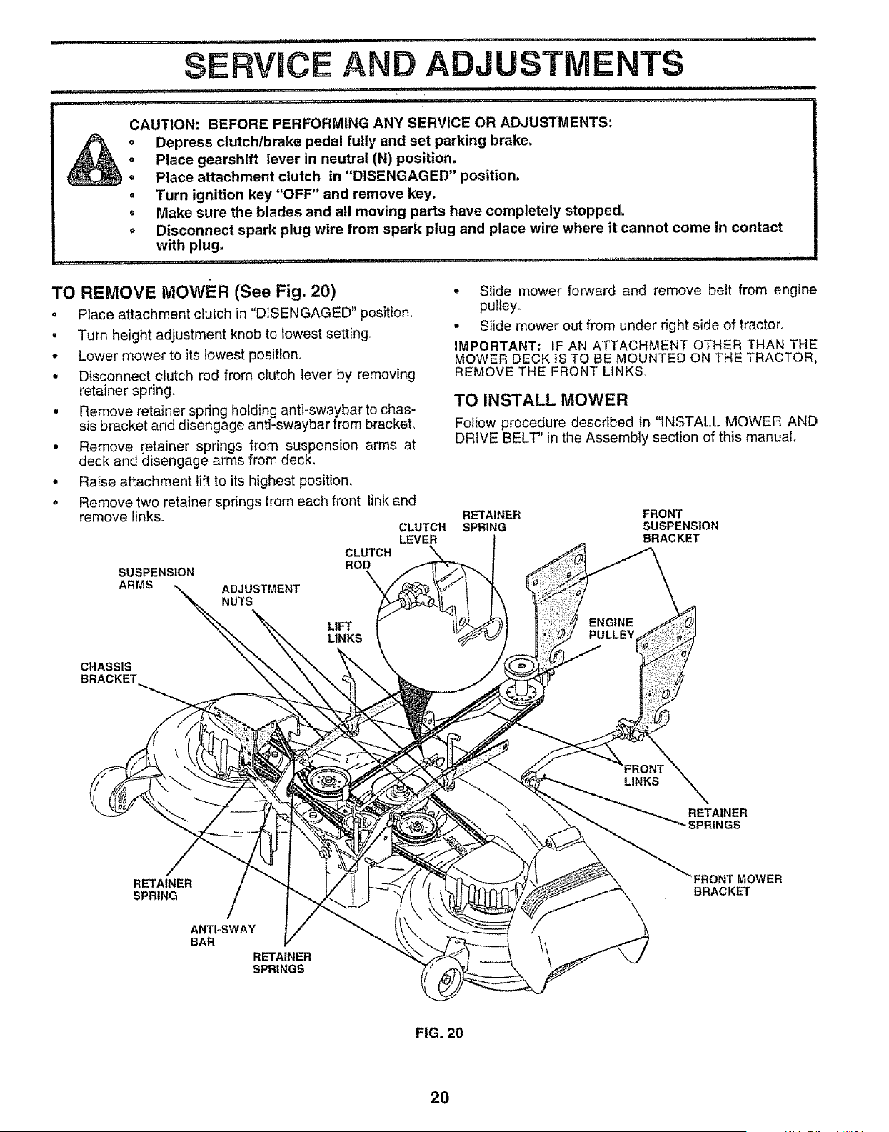
TO REMOVE MOWER (See Fig. 20)
° Place attachment clutch in "DISENGAGED" position,
• Turn height adjustment knob to lowest setting.
= Lower mower to its lowest position.
° Disconnect clutch rod from clutch lever by removing
retainer spring.
° Remove retainer spring holding anti-swaybar to chas-
sis bracket and disengage anti-swaybar from bracket.
° Remove retainer springs from suspension arms at
deck and disengage arms from deck.
° Raise attachment lift to its highest position.
° Remove two retainer springs from each front link and
remove links.
SUSPENSION
ARMS
ADJUSTMENT
NUTS
CLUTCH
ROD
LIFT
LINKS
CLUTCH
LEVER
• Slide mower forward and remove belt from engine
pulley.
• Slide mower out from under right side of tractor.
IMPORTANT; iF AN ATTACHMENT OTHER THAN THE
MOWER DECK iS TO BE MOUNTED ON THE TRACTOR,
REMOVE THE FRONT LINKS.
TO INSTALL MOWER
Follow procedure described in "INSTALL MOWER AND
DRIVE BELT" in the Assembly section of this manual.
RETAINER FRONT
SPRING SUSPENSION
BRACKET
ENGINE
PULLEY
CHASSIS
LINKS
RETAINER
"-,SPRINGS
RETAINER
SPRING
ANTI-SWAY
BAR
RETAINER
SPRINGS
FRONT MOWER
BRACKET
FIG. 20
20
Loading ...
Loading ...
Loading ...