Loading ...
Loading ...
Loading ...
AUXILIARY SIDE HANDLE (FIG. 1)
An auxiliary side handle isfurnished With
your grinder and can be screwed into
either side of the grinder housing. This
handle SHOULD BE USED AT ALL
TIMES to maintain complete control of the
tool.
ADJUSTING WHEEL GUARD (FIG. 2)
TURN OFF AND UNPLUG THE TOOL.
NEVER OPERATE GRINDER WITHOUT
GUARD IN PLACE.
Adjust the guard to protect your hands
and to direct grinding debris. Loosen the
clamp bolt. Position the guard at the
required angle. Always tighten the clamp
bolt.
.
.
Use only grinding wheels having a
maximum operating speed at least as
high as the speed specified in the
warning on the tool's labe =
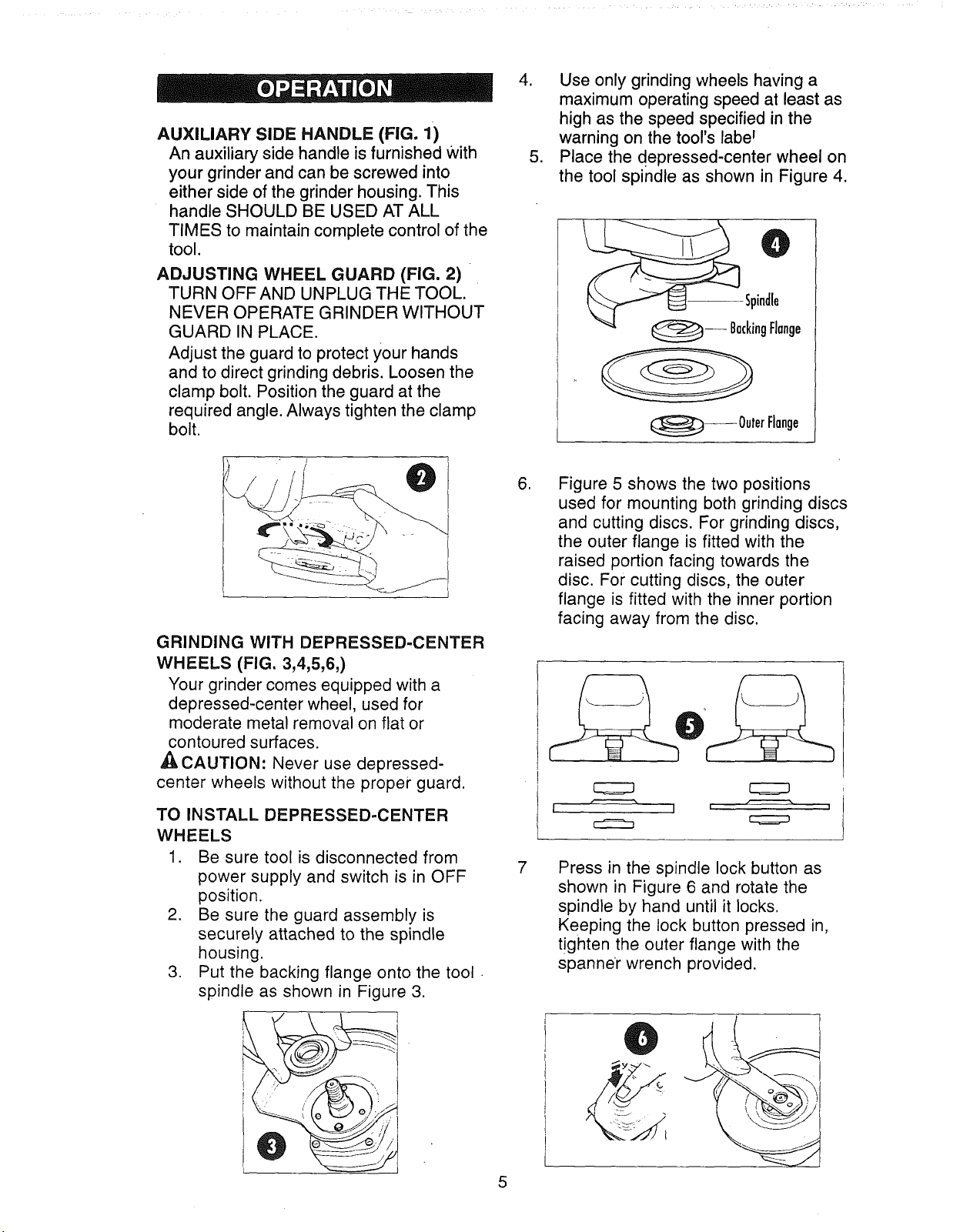
Place the depressed-center wheel on
the tool spindle as shown in Figure 4.
--Spindle
t_-- BackingFlange
@-- OuterFlange
GRINDING WITH DEPRESSED-CENTER
WHEELS (FIG. 3,4,5,6,)
Your grinder comes equipped with a
depressed-center wheel, used for
moderate metal removal on flat or
contoured surfaces.
,_, CAUTION: Never use depressed-
center wheels without the proper guard.
TO INSTALL DEPRESSED-CENTER
WHEELS
1. Be sure tool is disconnected from
power supply and switch is in OFF
position.
2. Be sure the guard assembly is
securely attached to the spindle
housing.
3. Put the backing flange onto the tool
spindle as shown in Figure 3.
.
7
Figure 5 shows the two positions
used for mounting both grinding discs
and cutting discs. For grinding discs,
the outer flange is fitted with the
raised portion facing towards the
disc. For cutting discs, the outer
flange is fitted with the inner portion
facing away from the disc.
I I L J
Press in the spindle lock button as
shown in Figure 6 and rotate the
spindle by hand until it locks.
Keeping the lock button pressed in,
tighten the outer flange with the
spanner wrench provided.
5
Loading ...
Loading ...
Loading ...