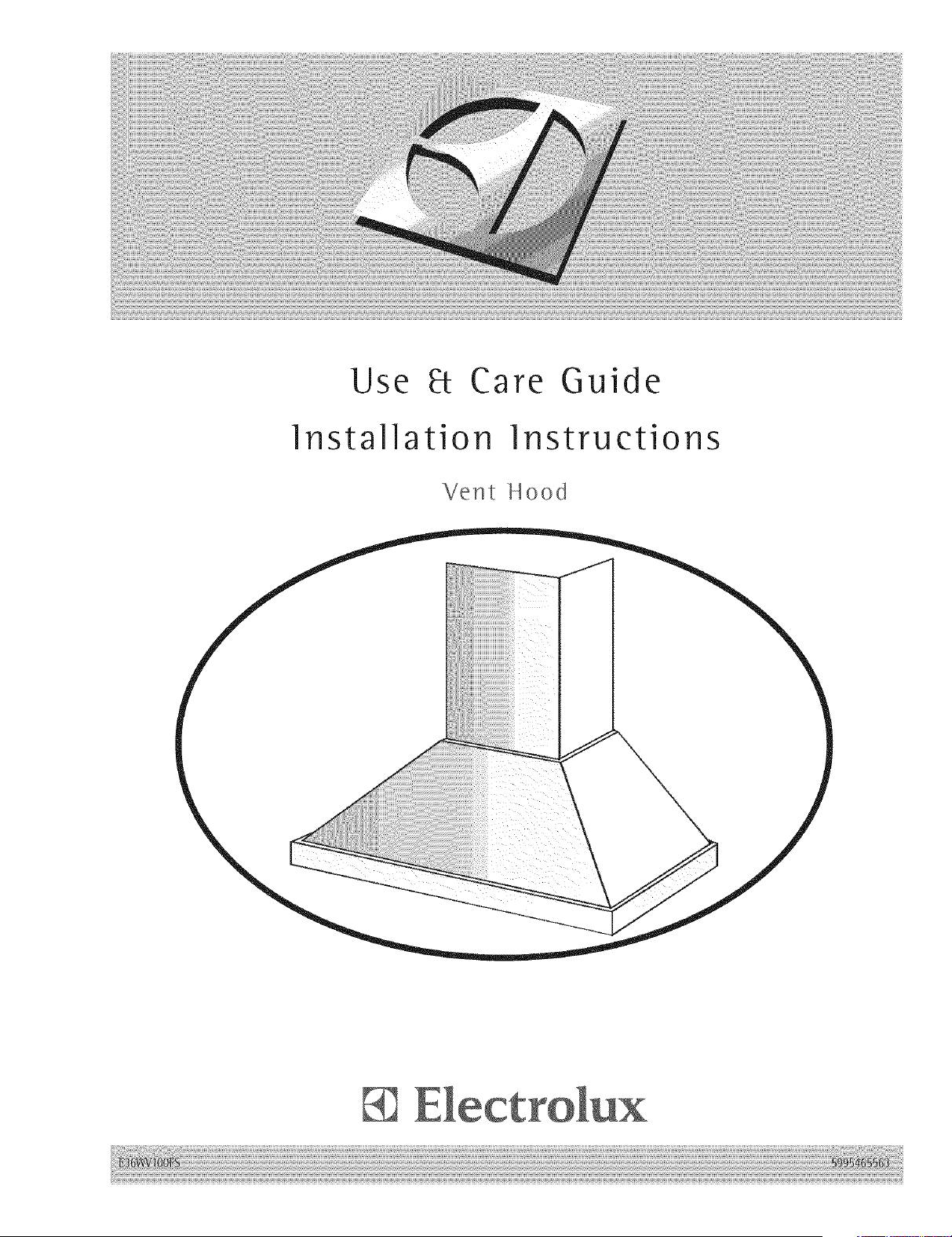
Use 8t Care Guide
Installation Instructions
Vent Hood

Fin i information
READANDSAVETHESEiNSTRUCTiONS
[] [] [] [] [] [] [] [] [] [] [] [] [] [] [] [] [] [] [] [] [] []
Read all instructions before installing the hood.
For your safety, please read and observe all safety instructions. This guide wilt
help you anticipate all installation connections.
[] [] [] [] [] [] [] [] [] [] [] [] [] [] []
For toll-free telephone support in the U.S. and Canada:
1=877= 4ELECTROLUX (1=877=435-3287)
For online support and Internet product information:
wv_.electrolu xusa.com
[] [] [] [] [] []
@2006 Electrolux Home Products, inc.
Post Office Box 212378, Augusta, Georgia 30917, USA
All rights reserved. Printed in the USA
i!ilii!!i!ii!!iiii!iiiiii!ii!iii!ii!i!iiiiii!ii!iii!!!iiiiiiiiiii!i
ioglnformationii i
.TA.%EOF.CON.T.EN.TS.,,,, , , , ,,,,,
F_nd_ng_nformat_on..............................................2
PleaseReadAndSaveThisGuide...................2
MakeA RecordForQuick Reference ................2
Questions...........................................................3
TableOfContents..............................................4
safety.....................................................................
ImportantSafetyInstructions.............................5
GeneralPrecautions..........................................6
oett_ngStarted......................................................8
OperatingYourHood.........................................8
CareandC_eaning...............................................1!
Cleaning the Filters andHcod ..........................11
installation...........................................................12
Planning.........................................12
Installation
VerifyingPackageContents.............................13
Installingthe Ducts..........................................14 .....
Installingthe HoodMountingBracket..............15
Installingthe Hood...........................................16
Installingthe Flue MountingBracket................16
Installingthe Electrical.....................................17
Connectingthe Ductwork.................................17
Installingthe Flue.............................................18
Installingthe Filters..........................................18
VerifyingOperation..........................................19
Troubleshooting ................................................20
IfServiceis Required.......................................20
TroubleshootingGuide.....................................21
EnergySavingTips..........................................22
Warranty information .........................................24
Safety
(MPORTANTSAFETY(NSTRUCT(ONS
[] [] [] [] [] [] [] [] [] [] [] [] [] [] [] [] [] [] [] [] [] []
Safety Precautions
Do not attempt to install or operate your unit until you have read the safety
precautions in this manual. Safety items throughout this manual are )abeted with a
Warning or Caution based on the risk type.
Definitions
/_ This is the safety alert symbol. It is used to alert you to potential personal injury
hazards. Obey all safety messages that follow this symbol to avoid possible injury
or death.
Safety
_( _ _ _ _ _ .... _ _ { _ a_ r_ _ /_ _
[] [] [] [] [] [] [] [] [] [] [] [] [] [] [] [] [] [] [] [] [] []
•Read all instructions before using this appliance.
•Install or locate this appliance only in accordance with these installation instructions.
•Do not operate this appliance if it has a damaged electrical conduit or wires, if it is not
working properly or if it has been damaged or dropped.
•To reduce the risk of fire, electric shock, or injury to persons, observe the following:
a) Instalation work and electrical wiring must be done by qualified person(s)
in accordance with all applicable codes and standards, including fire-rated
construction.
b) Sufficient air is needed for proper combustion and exhausting of gases through
the flue (chimney) of fuel burning equipment to prevent back drafting. Follow the
heating equipment manufacturer's guidelines and safety standards such as those
published by the National Fire Protection Association (NFPA), and the American
Society for Heating, Refrigeration and Air Conditioning Engineers (ASHRAE), and
the local code authorities.
c) When cutting or drilling into wall or ceiling, do not damage electrical wiring and
other hidden utlities.
d) Ducted fans must always be vented outdoors.
e) Use this unit only in the manner intended by the manufacturer, if you have
questions, contact the manufacturer.
f) Before servicing or cleaning unit, switch power off at service panel and lock
the service disconnecting means to prevent power from being switched on
accidentally. When the service disconnecting means cannot be locked, securely
fasten a prominent warning device, such as a tag, to the service panel.
•To reduce the risk of fire, use only metal ductwork.
•Grounding instructions
This appliance must be grounded. In the event of an electrical short circuit,
grounding reduces the risk of electric shock by providing an escape wire for the
electric current. This appliance is equipped with a cord having a grounding wire
with a grounding plug. The plug must be plugged into an outlet this is properly
installed and grounded.
• improper grounding can result in a risk of electric shock.
• Consult a qualified electrician if the grounding instructions are not completely
understood, or if doubt exists as to whether the appliance is properly grounded.
•Do not use this unit with any separate solid-state speed control device.
Safety
•Do not use an extension cord. If the power supply cord is too short, have a qualified
electrician install an outlet near the appliance.
• This appliance should be serviced only by qualified service personnel. Contact the
nearest Electrolux authorized servicer at (877) 435-3287, or at www.electroluxusa.com
for examination, repair or adjustment.
• If the information in this manual is not fol!owed exactly, a fire or explosion may resuff
causing property damage, personal injury, or death.
•Do not store or use gasoline or other flammable vapors and liquids in the vicinity of this
or any other appliance.
•Improper installation, adjustment, alteration, service, or maintenance can cause
personal injury or property damage. Refer to these instructions and the accompany-
ing Use & Care Manual. For assistance or additional information, consult a qualified
installer, service agency, or dealer.
•Keep appliance area clear and free from combustible material.
. For general ventilating use only. Do not use to exhaust hazardous or explosive
materials and vapors.
, To reduce the risk of a range top grease fire:
a) Never leave surface units unattended at high settings. Boilovers cause
smoking and greasy spillovers that may ignite. Heat oils slowly on low or
medium settings.
b) Nways turn hood ON when cooking at high heat or when cooking flaming
foods.
c) Clean ventilating fans frequently. Grease should not be allowed to accumulate
on fan or filter.
d) Use proper pan size. Always use cookware appropriate for the size of the
surface element.
Safety
•To reduce risk of fire and to properly exhaust air, be sure to duct air outside. Do not
vent exhaust air into spaces within walls or ceilings or into attics, crawl spaces, or
garages.
• Take care when using cleaning agents or detergents.
• Avoid using food products that produce flames under the Range Hood.
• For general ventilating use only. Do not use to exhaust hazardous or explosive
materials and vapors
• To avoid motor bearing damage and noisy and/or unbalanced impellers, keep drywall
spray, construction dust, etc. off power unit.
• Your hood motor has a thermal overload which will automatically shut off the motor if it
becomes overheated. The motor will restart when it cools down. If the motor continues
to shut off and restart, have the hood serviced.
•For best capture of cooking impurities, the bottom of the hood should be a minimum of
24" and amaximum of 30" above the cooking surface. See "Install Mounting Bracket"
section for mounting restrictions.
•Two installers are recommended because of the large size and weight of this hood.
° This product is equipped with a thermostat which may start blower automatically. To
reduce the risk of injury and to prevent power from being switched on accidentally,
switch power off at service panel and lock or tag service panel.
•Please read specification label on product for further information and requirements.
•Use with approved cord-connection kit only.
Started
OPERATINGYOUR HOOD
[] [] [] [] [] [] [] [] [] [] [] [] [] [] [] [] [] [] [] [] [] []
...._;i!i_i!_!i!i!_!i!i!_!i!i!_!i!i!_!i!i!_!i!i!_!i!i!_!i!i!_!i!i!_!i!i!_!i!_!i!i!_!i!i!_!i!i!_!i!i!_!i!i!_!i!i!_!i!i!_!i!i!_!i!i!_!i!i!_!i!i!_!i!i!_!i!i!_!i!i!_!i!i!_!i!i!_!i!i!|
LIGHT SLOWER
SWITCH SPEED
CONTROL
\
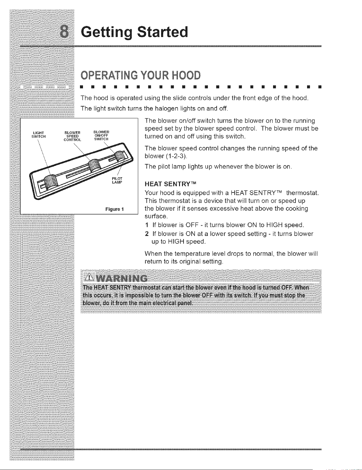
The hood is operated using the slide controls under the front edge of the hood.
The light switch turns the halogen lights on and off.
PILOT
LAMP
Figure 1
SLOWER
ON/OFF
SWITCH
The blower on/off switch turns the blower on to the running
speed set by the blower speed control. The blower must be
turned on and off using this switch.
The blower speed control changes the running speed of the
blower (1-2-3).
The pilot lamp lights up whenever the blower is on.
HEAT SENTRY TM
Your hood is equipped with a HEAT SENTRY TM thermostat.
This thermostat is a device that will turn on or speed up
the blower if it senses excessive heat above the cooking
surface.
1 If blower is OFF - it turns blower ON to HIGH speed.
2 If blower is ON at a lower speed setting - it turns blower
up to HIGH speed.
When the temperature level drops to normal, the blower will
return to its original setting.
Operation
HALOGEN BULBS
[] [] [] [] [] [] [] [] [] [] [] [] [] [] [] [] [] [] [] [] []
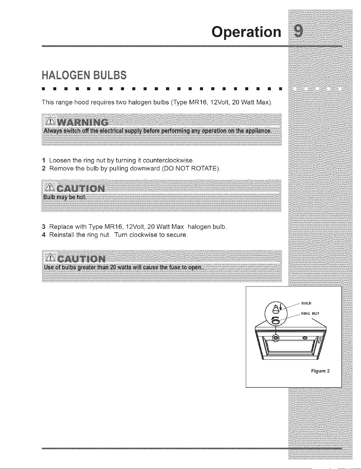
This range hood requires two halogen bulbs (Type MR16, 12Volt, 20 Watt Max).
1 Loosen the ring nut by turning it counterclockwise.
2 Remove the bulb by pulling downward (DO NOT ROTATE).
3 Replace with Type MR16, 12Volt, 20 Watt Max halogen bulb.
4 Reinstall the ring nut. Turn clockwise to secure.
BULB
RiNG NUT
Figure 2
Operation
FUSE REPLACEMENT
[] [] [] [] [] [] [] [] [] [] [] [] [] [] [] [] [] [] [] [] [] []
ELECTRICAL BOX
TR M SUPPORT SCREWS
TRiM SCREWS Figure 3
FUSE
{ICAL
RT
FUSE J
BOX
Figure 4
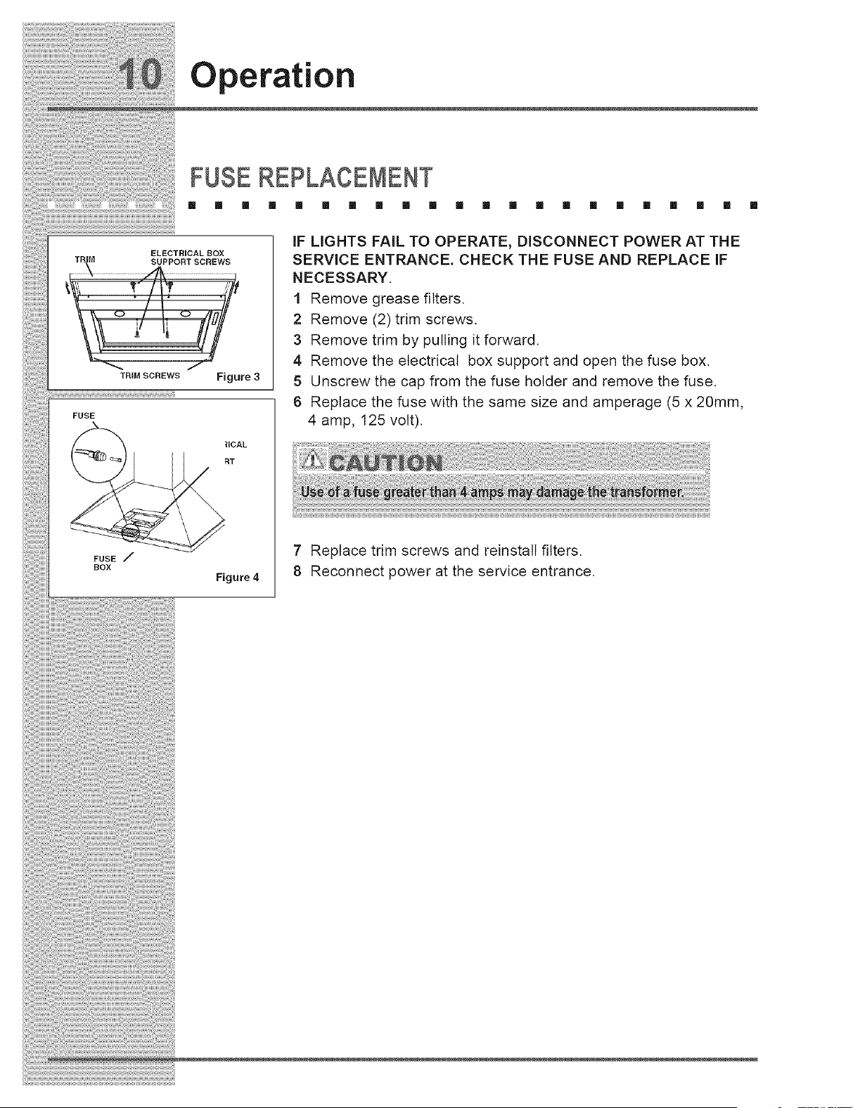
IF LIGHTS FAIL TO OPERATE, DISCONNECT POWER AT THE
SERVICE ENTRANCE. CHECK THE FUSE AND REPLACE IF
NECESSARY.
1 Remove grease filters.
2 Remove (2) trim screws.
3 Remove trim by pulling it forward.
4 Remove the electrical box support and open the fuse box.
5 Unscrew the cap from the fuse holder and remove the fuse.
6 Replace the fuse with the same size and amperage (5 x 20mm,
4 amp, 125 volt).
7 Replace trim screws and reinstall filters.
8 Reconnect power at the service entrance.
iiiiiiiii!iiiii!iiiiiiii!iiiii!!i!!!i!ii!iiiiiiiiii!!ii!iiii!i!jiiiiiii!i!!iiii!iiiiiiii!i!i!iiiiiii!iiiiiiiiiiiiliiii!i
Care and Clean=n _'
3 3. . . . . . .
Proper maintenance of the Range Hood will assure proper performance of the unit.
Grease Filters
The grease filters should be cleaned frequently. Use a warm detergent solution.
Grease filters are dishwasher safe.
See '1NSTALL FI LTE RS"' section for removal and installation instructions.
.codc_°_°g
Stainless steel is one of the easiest materials to keep clean. Occasional care will
help preserve its fine appearance.
Cleaning tips:
1 Hot water with soap or detergent is all that is usually needed.
2 Follow all cleaning by rinsing with clear water. Wipe dry with a clean, soft cloth ]
to avoid water marks.
3 For discolorations or deposits that persist, use a non-scratching household
cleanser or stainless steel polishing powder with a littte water and a soft cloth.
4 For stubborn cases, use a plastic scouring pad or soft bristle brush together
with cleanser and water. Rub lightly in direction of polishing lines or "grain" of the .....
stainless finish. Avoid using too much pressure which may mar the surface.
5 DO NOT allow deposits to remain for long periods of time.
6 DO NOT use ordinary steel wool or steel brushes. Small bits of steel may
adhere to the surface causing rust.
7DO NOT allow salt solutions, disinfectants, bleaches, or cleaning compounds
to remain in contact with stainless steel for extended periods. Many of these
compounds contain chemicals which may be harmful. Rinse with water after
exposure and wipe dry with a clean cloth.
Painted surfaces should be cleaned with warm water and mild detergent only.
installation
INSTALLATIONPLANNING
[] [] [] [] [] [] [] [] [] [] [] [] [] [] [] [] [] [] [] [] [] []
A qualifiedinstallermust complete the installationof thisbuilt-inappliance.Proper
installationisyour responsibility.
Carefullycheck the locationwhere the hood isto be installed.The hood should be
placed forconvenient access. Make certainthatelectricalpower can be provided
inthe selected location.
Plan the installationso thatallminimum clearances are met or exceeded.
Dimensions shown provide minimum clearances,unless otherwise noted.
The specifiedminimum cabinetdepth and width must be provided.
Cabinet cutoutdimensions must be used as indicated.Allcontactsurfaces
between the appliance and the cabinet must be solidand level.
Make certain that you have everything necessary to ensure aproper
installation before proceeding.
installation
VERIFYPACKAGE CONTENTS
[] [] [] [] [] [] [] [] [] [] [] [] [] [] []
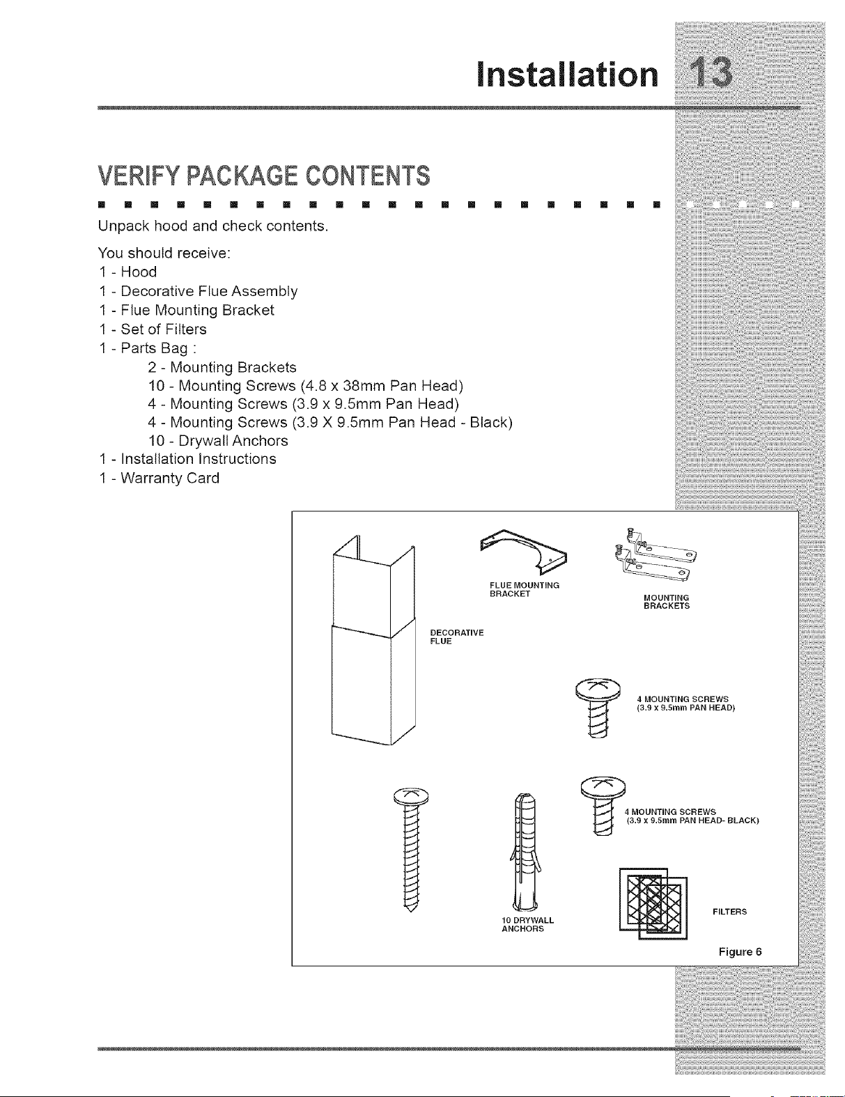
Unpack hood and check contents.
You should receive:
1 - Hood
1 - Decorative Flue Assembly
1 - Flue Mounting Bracket
1 - Set of Filters
1 - Parts Bag :
2 - Mounting Brackets
10 - Mounting Screws (4.8 x 38mm Pan Head)
4 - Mounting Screws (3.9 x 9.5mm Pan Head)
4 - Mounting Screws (3.9 X 9.5mm Pan Head - Black)
10 - Drywall Anchors
1 - Installation Instructions
1 - Warranty Card
[] [] [] [] [] []
FLUE MOUNTING
BRACKET
"_ DECORATIVE
FLUE
MOUNTING
BRACKETS
4MOUNTING SCREWS
(3.gx9.5mm PAN HEAD)
1ODRYWALL
ANCHORS
FILTERS
Figure 6
(nstallation
iNSTALLiNG THE DUCTS
[] [] [] [] [] [] [] [] [] [] [] [] [] [] [] [] [] [] [] [] [] []
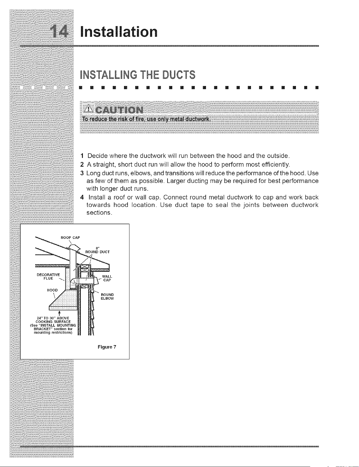
1 Decide where the ductwork will run between the hood and the outside.
2 A straight, short duct run will allow the hood to perform most efficiently.
3 Long duct runs, elbows, and transitions will reduce the performance of the hood. Use
as few of them as possible. Larger ducting may be required for best performance
with longer duct runs.
4 Install a roof or wall cap. Connect round metal ductwork to cap and work back
towards hood location. Use duct tape to seal the joints between ductwork
sections.
ROOF CAP
\
8"
ROUND DUCT
DECORATIVE
FLUE _
HOOD
WALL
CAP
ROUND
ELBOW
+
24" TO 30" ABOVE
COOKING SURFACE
(See "iNSTALL MOUNTING
BRACKET" section for
mounting restrictions)
Figure 7
(nstallation
(NSTALL(NGTHE HOOD MOUNT(NGBRACKET
[] [] [] [] [] [] [] [] [] [] [] [] [] [] [] [] [] [] [] [] [] []
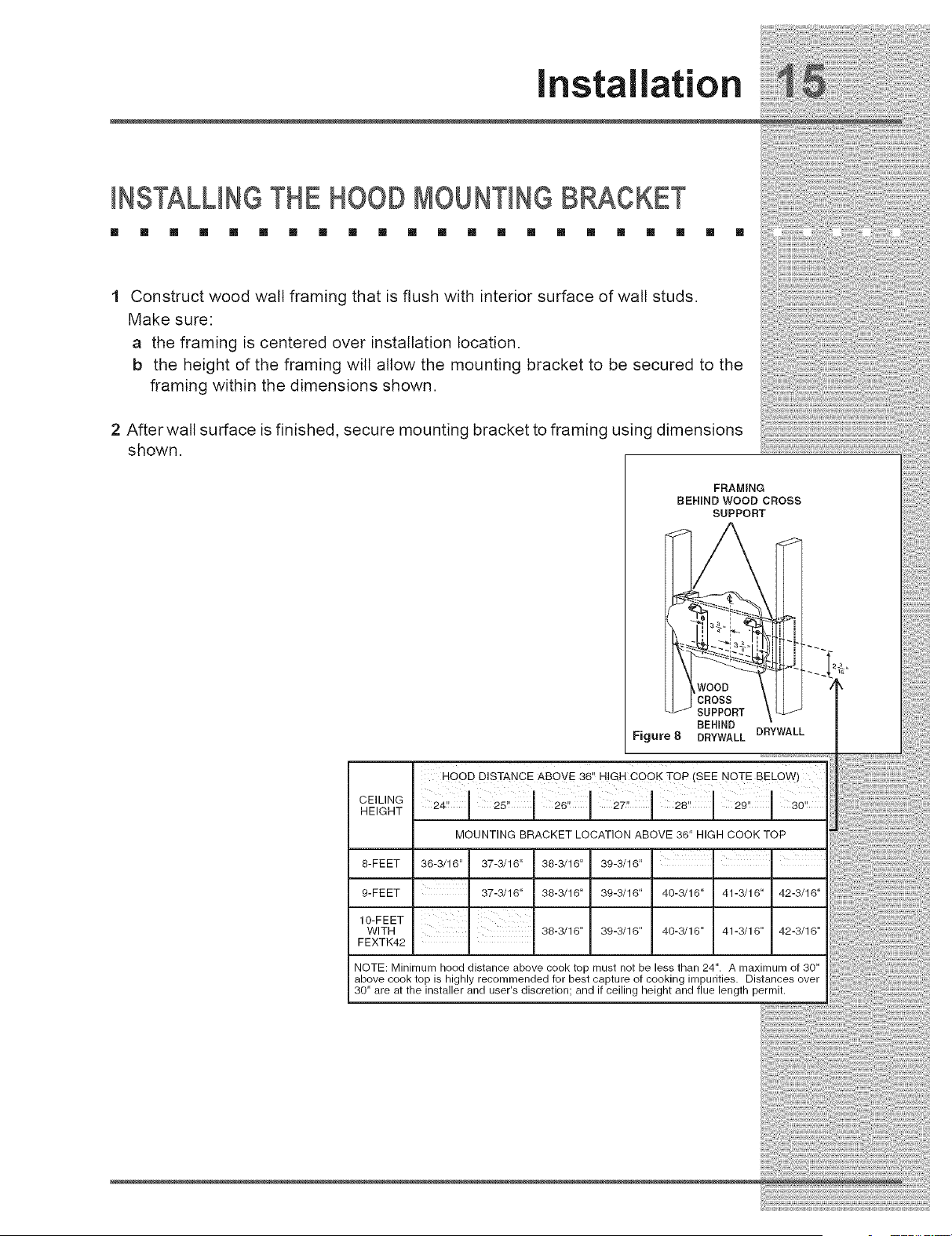
Construct wood walt framing that is flush with interior surface of wall studs.
Make sure:
a the framing is centered over installation location.
b the height of the framing will allow the mounting bracket to be secured to the
framing within the dimensions shown.
2 After wall surface is finished, secure mounting bracket to framing using dimensions
shown.
FRAMING
BEHIND WOOD CROSS
SUPPORT
-i
..=
SUPPORT J
BEHIND DRYWALL
Figure 8 DRYWALL
HOOD DISTANCE ABOVE 36" HIGH COOK TOP (SEE NOTE BELQW)
CEILING
HEIGHT
MOUNTING BRACKET LOCATION ABOVE 36" HIGH COOK TOP
8-FEET 36-3/16" 37-3/16" 38-3/16" 39-3/16"
9- FE ET 37-3/16" 38-3/16" 39-3/16" 40-3/16" 41-3/16" 42-3/16"
IO-FEET I
WITH 38-3/16" 39-3/16" 40-3/16" 41-3/16" 42-3/16"
FEXTK42
NOTE: Minimum hood distance above cook top must not be less than 24". A maximum of 30"
above cook top is highly recommended for best capture of cooking impurities. Distances over
30" are at the installer and user's discretion; and if ceiling height and flue length permit.
iiiii_ii!i!i_!!ililili!ii!_!i!i!i!!j_ili_i_ii!i_iiii_i_i_i_!_ii_!J_!i_ii!_i!ii!i!i_!i_i_!i_i_!i_i_!ii_!i:i_i!_iiii_i_!_i_i_ii_!i_!iiii!_i_!!_i_!!i_i_ii!i_i_!;!ii_!!i_i_iiii_i!i_iiiii!_!!_!;!_J;_!S;_!_!!!_ii_i!i_!i_i!ii!_!_
1_ Installation
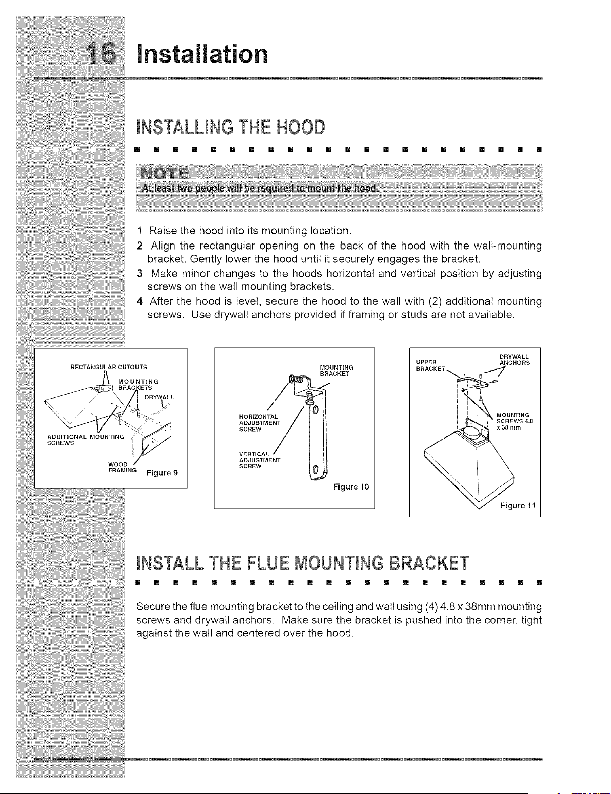
1 Raise the hood into its mounting location.
2 Align the rectangular opening on the back of the hood with the walt-mounting
bracket. Gently lower the hood until it securely engages the bracket.
3Make minor changes to the hoods horizontal and vertical position by adjusting
screws on the wall mounting brackets.
4 After the hood is level, secure the hood to the walt with (2) additional mounting
screws. Use drywall anchors provided if framing or studs are not available.
RECTANGULAR CUTOUTS
MOUNTING
BRACKETS
JDRYV_ALL
ADDiTiONAL MOUNTING
SCREWS
WOOD
FRAMING Figure 9
MOUNTING
BRACKET
HORIZONTAL
ADJUSTMENT
SCREW
VERTICAL
ADJUSTMENT
SCREW
Figure 10
UPPER
DRYWALL
ANCHORS
MOUNTING
x38 mm
Figure 11
IHSTALL THE FLUE MOUHTIHGBRACKET
[] [] [] [] [] [] [] [] [] [] [] [] [] [] [] [] [] [] [] [] [] []
Secure the flue mounting bracket to the ceiling and wall using (4) 4.8 x 38mm mounting
screws and drywall anchors. Make sure the bracket is pushed into the corner, tight
against the wall and centered over the hood.

installation
INSTALLINGTHE ELECTRICAL
[] [] [] [] [] [] [] [] [] [] [] [] [] [] [] [] [] [] [] [] [] []
1 Run 120 VAC electrical power cable to the hoods wiring box.
2 Remove the cover from the wiring box and remove one knockout.
3 Feed 6" of cable through the knockout opening and secure the cable
to the wiring box with an appropriate connector.
4 Make electrical connections at the hood. Connect white-to-white, black-
to-black, and green-to-ground.
5 Replace the wiring box cover and screws. Make sure wires are not
pinched between the cover and box.
POWER CONNECTION AT HOOD
CONNECT:
WHITE-TO-WHITE
BLACK-TO-BLACK
GREEN-TO-GROUND
120 VOLT 60
HZ LINE-IN
Figure 12
CONNECTINGTHE DUCTWORK
[] [] [] [] [] [] [] [] [] [] [] [] [] [] [] [] [] [] []
1 Install an adequate length of 8" diameter steel ducting to the range
hood's duct connector.
2 Connect the duct work between the range hood and duct leading to
the outside location.
3 Duct tape all joints to make them secure and air tight.
[] [] []
¸i!,,,!
8" ROUND
DUCT _ LI i
Figure 13
Installation
INSTALLINGTHE FLUE
[] [] [] [] [] [] [] [] [] [] [] [] [] [] [] [] [] [] [] [] [] []
FLUE MOUNTING BRACKET
UPPER
FLUE
LOWER
HOOD
Figure 14
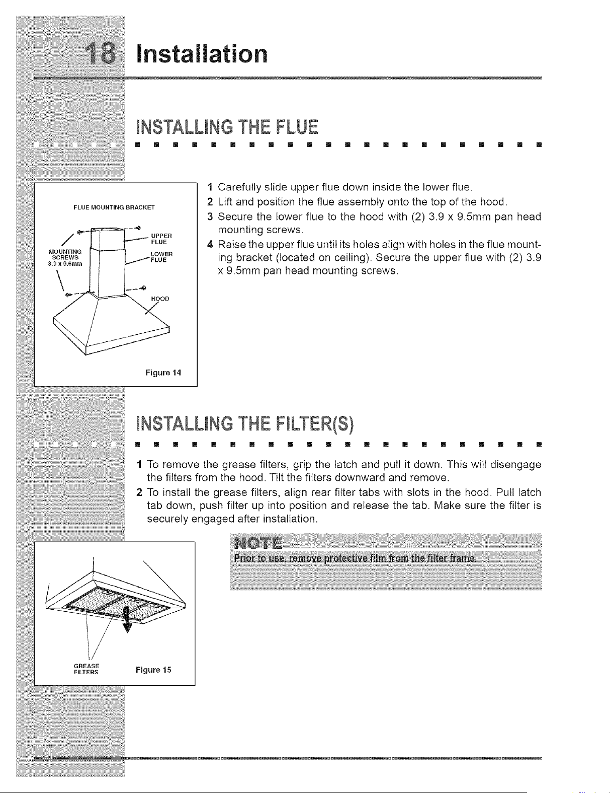
1 Carefully slide upper flue down inside the lower flue.
2 Lift and position the flue assembly onto the top of the hood.
3 Secure the lower flue to the hood with (2) 3.9 x 9.5mm pan head
mounting screws.
4 Raise the upper flue until its holes align with holes in the flue mount-
ing bracket (located on ceiling). Secure the upper flue with (2) 3.9
x 9.5mm pan head mounting screws.
INSTALLINGTHE FILTER(S)
[] [] [] [] [] [] [] [] [] [] [] [] [] [] [] [] [] [] [] [] [] []
1 To remove the grease filters, grip the latch and pull it down. This will disengage
the filters from the hood. Tilt the filters downward and remove.
2 To install the grease filters, align rear filter tabs with slots in the hood. Pull latch
tab down, push filter up into position and release the tab. Make sure the filter is
securely engaged after installation.
GREASE
FILTERS Figure 15

installation
VERIFYING OPERATION
[] m [] [] [] [] m m m m [] [] [] m m m m m [] [] [] m
e
e
e
e
e
Install the filters.
Verify that the hood control knobs are in the OFF position.
Turn on the main power supply,
Slide light switch to the ON position, Lights should illuminate,
Slide blower switch to the ON position, Then slide the speed control
switch to check operation of the variable speed,
Turn off light switch and blower switch,
Troubleshooti
IF SERVICE IS REQUIRED
[] [] [] [] [] [] [] [] [] [] [] [] [] [] [] [] [] [] [] []
First, review the recommended checks listed in the Troubleshooting Guide.
Then, be certain that the appliance has been installed properly and is being
operated correctly. Familiarize yourself with the warranty terms and conditions
listed in the Warranty section.
If the above checks have been completed and the problem has not yet been
remedied, contact the dealer where you purchased the unit. State the Model and
Serial number and explain the problem. The Model and Serial number plate is
located inside the unit at upper right hand corner.
If you do not know the name of the selling dealer or local service company, you
can check online at www.electroluxusa.com.
[] []
Troubleshootin
TROUBLESHOOTINGGUIDE
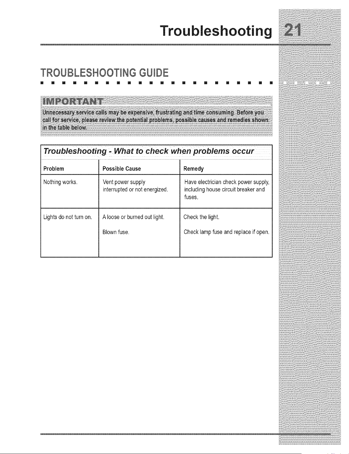
Troubleshooting: What tocheck when problems occur
Problem Possible Cause Remedy
Nothing works. Vent power supply Have electrician check power supply,
interrupted or not energized, including house circuit breaker and
fuses.
Lights do not turn on. A loose or burned out light.
Blown fuse.
Check the light.
Check lamp fuse and replace if open.
iiiiiiiiiiiiiii!i!!i_i!i__i_i!i_i_i!i_i_i!i_i_i!i_i_i!i_ii_!_i!!__iii_!i_ii_!iii_i!i!__i!!!___!!!___!!!iiii_i!iii!!i!i!i!i!i!i_i!!!i!i!!_i!i!i_i_i!_i_i!i_;!i_____!iiii_!i_ill_ii_!___!i_i_!_i_!_!i!i!_!i_i_i!i_!_!i_!i!i!i!i!i!i!_!i!i!i!ii_ii_ii!_!i_ii!i__!_i!iii_i_i_i!i!i_i!i!ii_!!_i_i_i_i_i_i_i_i_i_;i__i_i!i_
_Savin Energy
,E,.E.RG.Y.SA.VU.,G.T!PS.............
1 Do not operate the blower at a speed that is higher than necessary to
remove the cooking exhaust. Running at excessive speeds removes more air
from the inside of the house that must be replaced by outside air. This may
be especially costly when the housing air conditioning or heating system is in
ope_t_o_
2 Clean filters and grease-laden surfaces often to improve efficiency.
3 Turn off the blower as soon as all cooking smoke and odors have been
eliminated.
4 Always use lids on cookware to retain heat and moisture.
5 Minimize the amount of liquid used to cook food.
6 Select cookware of the proper size, material and construction for the cooking
task being performed.

i__ ¸¸¸¸¸¸............
Warranty
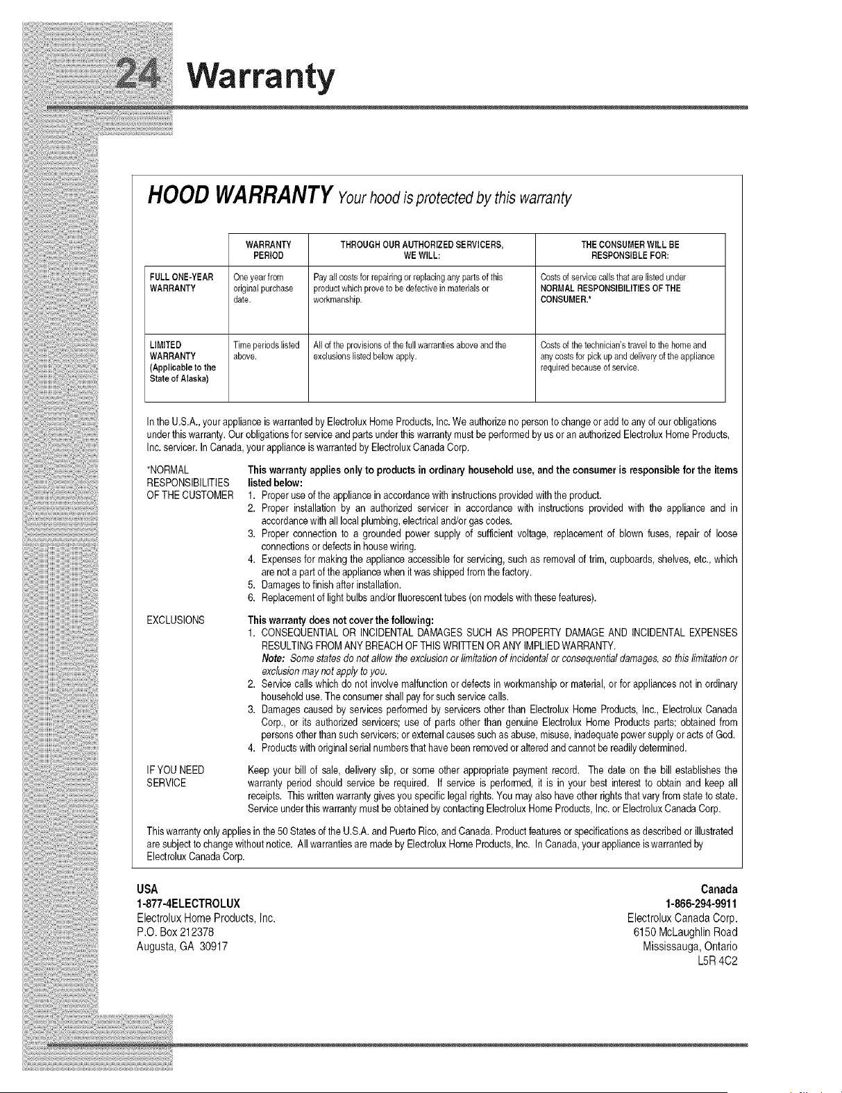
HOODWARRANTYYourhoodisprotected by this warranty
WARRANTY THROUGHOURAUTHORIZEDSERVICERS, THECONSUMERWILLBE
PERIOD WEWILL: RESPONSIBLEFOR:
FULLONE-YEAR Oneyearfrom Payallcostsforrepairingor replacinganypartsofthis Costsofservicesailsthatarelistedunder
WARRANTY originalpurchase productwhichproveto bedefectiveinmaterialsor NORMALRESPONSIBILITIESOFTHE
date. workmanship. CONSUMER.*
LIMITED Timeperiodslisted Alloftheprovisionsofthefullwarrantiesaboveandthe Costsofthetechnician'straveltothehomeand
WARRANTY above, exclusionslistedbelowapply, anycostsforpickupanddelivel7 oftheappliance
(Applicableto the requiredbecauseofservice.
Stateof Alaska)
In the U.S.A., yourapplianceis warrantedby ElectroluxHomeProducts,Inc.We authorizeno personto changeor add to any dour obligations
underthis warranty.Our obligationsfor serviceand partsunderthis warrantymust beperformedby us oran authorizedElectroluxHomeProducts,
Inc. servicer.In Canada,your applianceis warrantedby ElectroluxCanadaCorp.
*NORMAL Thiswarranty applies onlyto products in ordinary household use, and the consumer is responsible for the items
RESPONSIBILITIES listed below:
OF THE CUSTOMER 1. Properuseof the appliancein accordancewith instructionsprovidedwiththe product.
2. Proper installation by an authorized servicer in accordance with instructions provided with the appliance and in
accordancewith all localplumbing,electricaland/orgascodes.
3. Proper connectionto a grounded power supply of sufficient voltage, replacementof blown fuses, repair of loose
connectionsor defectsin housewiring.
4. Expensesfor makingthe applianceaccessiblefor servicing,such as removalof trim, cupboards,shelves,etc., which
are not a part of the appliancewhen it wasshippedfromthe factory.
5. Damagesto finish after installation.
6. Replacementof light bulbsand/orfluorescenttubes (on modelswith these features).
EXCLUSIONS This warranty does not cover the following:
1. CONSEQUENTIALOR INCIDENTALDAMAGES SUCH AS PROPERTYDAMAGE AND INCIDENTALEXPENSES
RESULTINGFROMANY BREACHOF THISWRITTENOR ANYiMPLIEDWARRANTY.
Note: Somestates do not allow the exclusionor limitationof incidentalor consequentialdamages,so this limitationor
exclusionmaynot applyto you.
2. Servicecallswhichdo not involvemalfunctionor defectsin workmanshipor material,or for appliancesnot in ordinary
householduse.The consumershallpayfor such servicecalls.
3. Damagescaused by services performedby servicersother than ElectroluxHome Products,Inc., ElectroluxCanada
Corp., or its authorizedservicers; use of parts other than genuine Electrolux Home Products pads; obtainedfrom
personsotherthansuch servicers;or externalcausessuch asabuse, misuse,inadequatepowersupplyoracts of God.
4. Productswithoriginalserialnumbersthat have beenremovedor alteredand cannotbe readilydetermined.
IF YOUNEED Keep your bill of sale, delivery slip, or some other appropriatepayment record. The date on the bill establishesthe
SERVICE warranty period should service be required. If service is performed,it is in your best interest to obtain and keep all
receipts. This writtenwarrantygivesyou specificlegal rights.You may also haveother rightsthat vary from stateto state.
Serviceunderthis warrantymust beobtainedby contactingElectroluxHome Products,Inc.or ElectroluxCanadaCorp.
Thiswarrantyonly appliesin the50 Statesof the U.S.A.and PuertoRico,and Canada.Productfeatures or specificationsasdescribedor illustrated
are sub ectto changewithoutnotice. All warrantiesare madeby ElectroluxHomeProducts,Inc. In Canada,your applianceiswarrantedby
ElectroluxCanadaCorp.
USA Canada
1-877-4ELECTROLUX 1-866-294-9911
Electrolux Home Products, Inc. Electrolux Canada Corp.
P.O. Box 212378 6150 McLaughlin Road
Augusta, GA 30917 Mississauga, Ontario
LhR 4C2