User Manual and
Installation Instructions
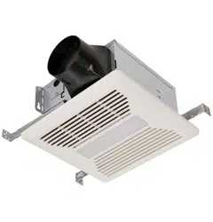
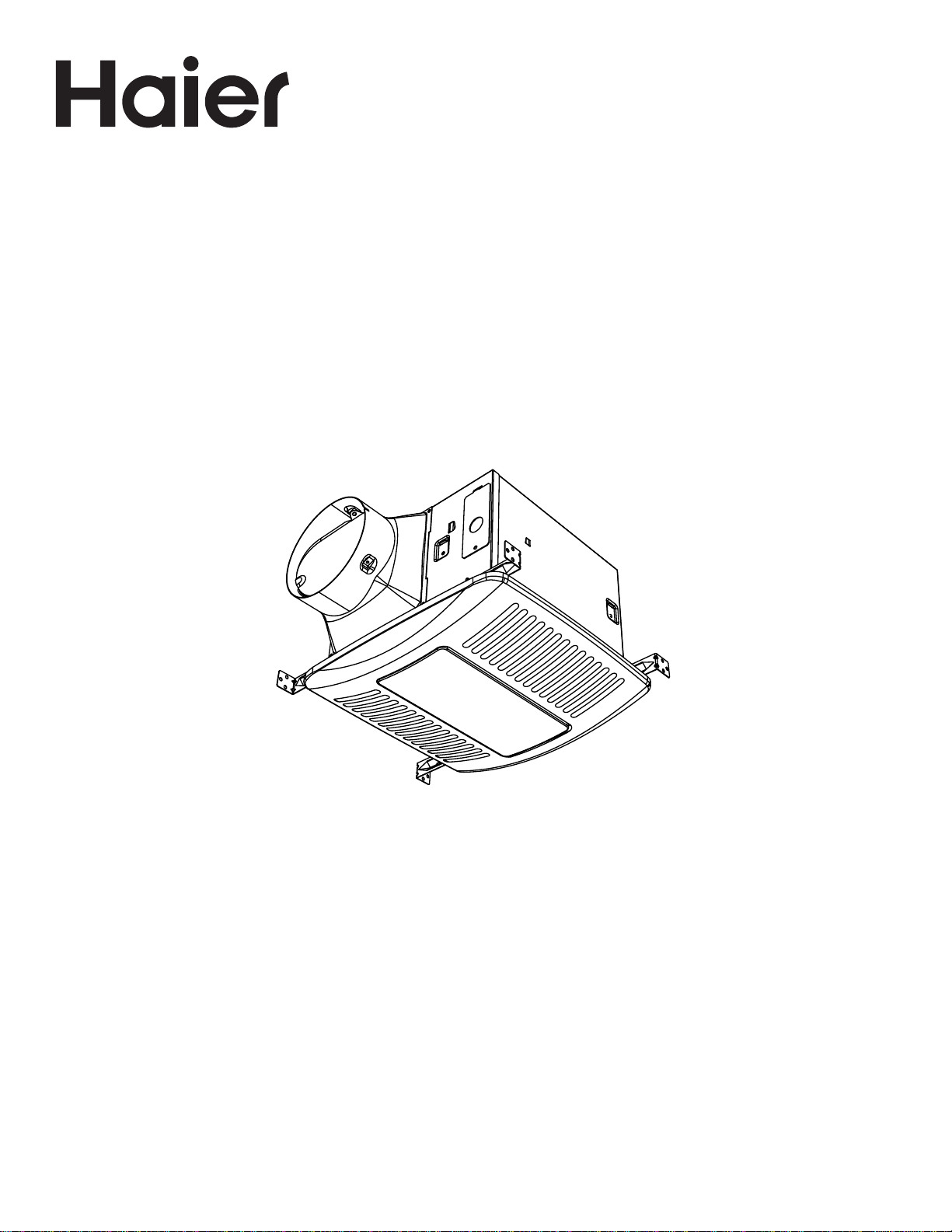
QVE110DTWW
Adjustable CFM Exhaust Fan
49-7000175 Rev. 3 02-22 GEA
ESPAÑOL
Para consultar una version en español
de este manual de instrucciones,
visite nuestro sitio de internet
Haierappliances.com.


49-7000175 Rev. 3 3
ENGLISH
RECORD KEEPING
Thank you for purchasing this Haier product. This user manual
will help you get the best performance from your new exhaust
fan.
For future reference, record the model and serial number
located on a label inside the housing.
Staple your proof of purchase to this manual to aid in
obtaining warranty service if needed.
____________________________________________________
Model number
____________________________________________________
Serial number
____________________________________________________
Date of purchase
TABLE OF CONTENTS
SAFETY INFORMATION ............................................................................................4
USING THE EXHAUST FAN .........................................................................................5
PRODUCT CARE ..................................................................................................8
INSTALLATION INSTRUCTIONS ....................................................................................8
TROUBLESHOOTING TIPS ........................................................................................14
LIMITED WARRANTY ............................................................................................ 15
HAIER WEBSITE
Have a question or need assistance with your appliance? Try the Haier Website 24 hours a day, any day of the year! You
can also shop for more great Haier products and take advantage of all our on-line support services designed for your
convenience. In the US: Haierappliances.com
Register Your Appliance
Register your new appliance on-line at your convenience! Timely product registration will allow for enhanced communication
and prompt service under the terms of your warranty, should the need arise.
• Scan QR Code on product registration card, or on product.
NOTE: This is just an example of what a QR code represents.
• Or go to Haierappliances.com/register
• Or mail in your pre-printed registration card included in the packing material
4 49-7000175 Rev. 3
ENGLISH
READ AND SAVE THESE INSTRUCTIONS
IMPORTANT SAFETY INFORMATION
READ ALL INSTRUCTIONS BEFORE USING THE APPLIANCE
SAFETY INFORMATION
WARNING
TO REDUCE THE RISK OF FIRE,
ELECTRIC SHOCK OR INJURY TO PERSONS, OBSERVE
THE FOLLOWING:
A. Use this unit only in the manner intended by the
manufacturer. If you have questions, contact the
manufacturer.
B. Before servicing or cleaning unit, switch power off at
service panel and lock the service disconnecting means
to prevent power from being switched on accidentally.
When the service disconnecting means cannot be
locked, securely fasten a prominent warning device,
such as a tag, to the service panel.
C. This unit must be grounded.
D. Do not use this fan with any solid-state speed control
device.
CAUTION
FOR GENERAL VENTILATING USE
ONLY. DO NOT USE TO EXHAUST HAZARDOUS OR
EXPLOSIVE MATERIALS AND VAPORS.
E. Please read specification label on product for further
information and requirements.
PROPER DISPOSAL OF YOUR APPLIANCE
Dispose of or recycle your product in accordance with Federal and Local Regulations. Contact your local authorities for
the environmentally safe disposal or recycling of your product.
49-7000175 Rev. 3 5
ENGLISH
USING THE EXHAUST FAN
OPERATION
NOTE: Make sure the wall switches are in OFF position
before making any control modifications.
This exhaust fan has the following features for customer
convenience:
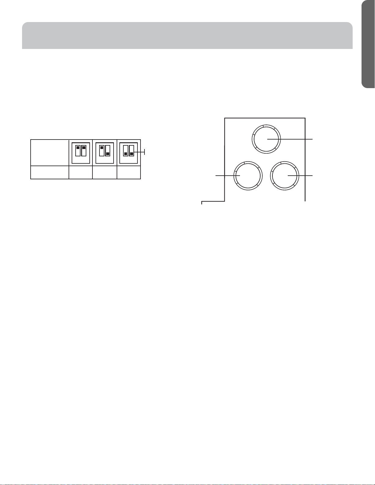
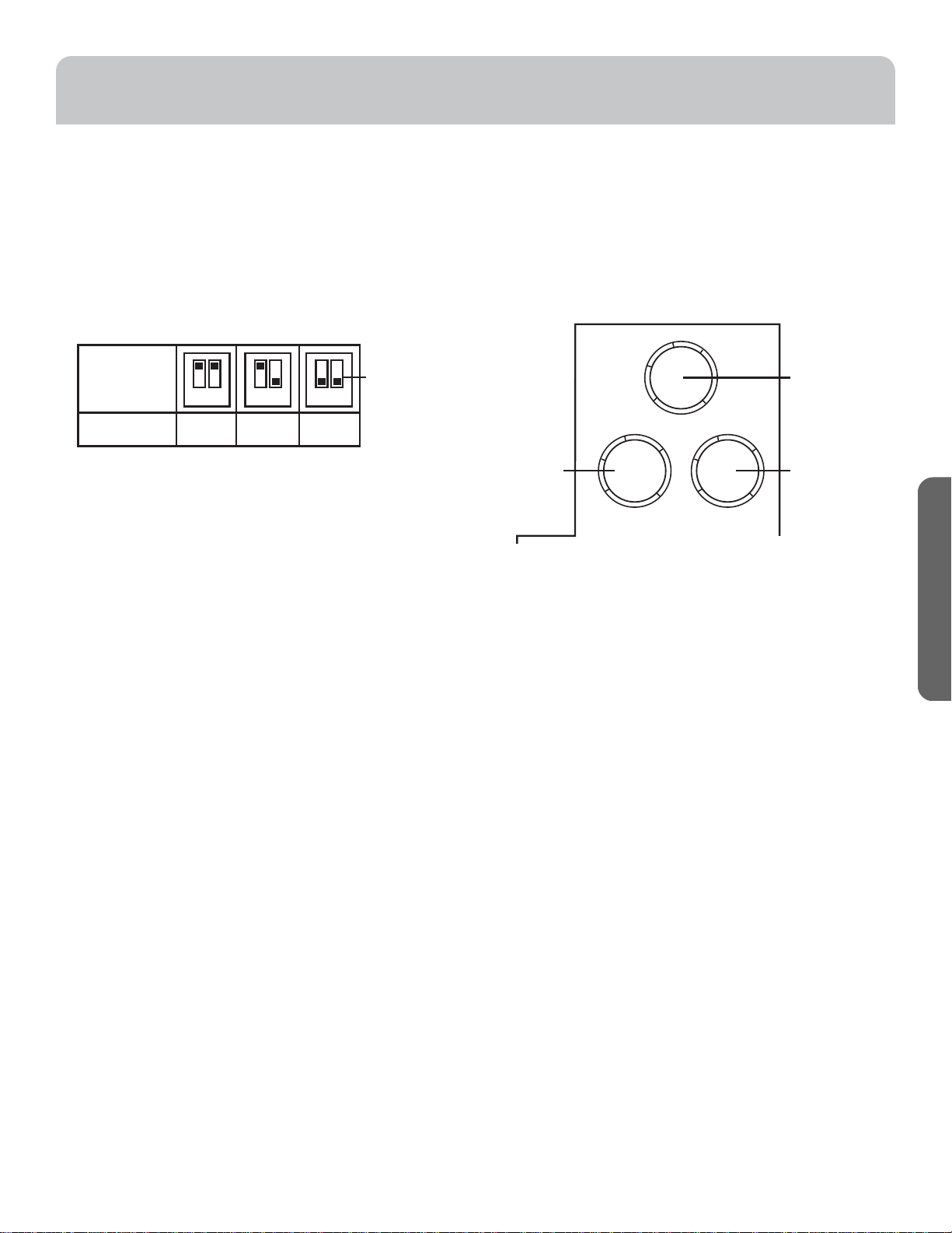
• CFM Adjustment Toggle Switch: Users can set fan output
to 80, 110, or 140 CFM by adjusting the toggle switch
position 1 and 2 as per the illustration. Fan is factory set to
110 CFM.
• Humidity Sensor Selector (H): When the relative humidity
% exceeds the set humidity sensor setting, the fan will run
at chosen CFM setting. If the fan continuously responds
to changing environmental conditions (too sensitive), the
humidity sensor setting may need to be adjusted. Factory
set position is OFF.
• Low Air Flow Setting Selector (S): Users can set fan's
continuous ventilation low air flow output at 30 cfm or at
a percentage of the set toggle switch CFM. Factory set
position is OFF.
• Delay Timer Selector (T): Sets the amount of time that the
fan will continue to run per the toggle switch setting after
the wall switch is turned OFF. If humidity sensor is set the
fan will continue to run for selected delay time after the
ambient humidity decreases below the humidity sensor
setting. Factory set position is OFF.
The functionality of these features depends on your
wall switch wiring setup. Refer to the section CONNECT
ELECTRICAL for the wall switch connection wiring diagrams.
If the fan and light are wired to a single wall switch, only the
CFM Adjustment Toggle Switch Feature will be activated and
the fan will run as per the set CFM.
Refer to the sections below for two function or three
function wall switch functionality.
NOTE: It is normal for the fan to take a few seconds to start
running once the wall switch is turned on.
T
H
OFF
30%
45%
60%
80%
60min
20min
40min
OFF
5min
S
OFF
Max.
60%
80%
30
CFM
Humidity
sensor select
o
Time delay Low airflow
selectorsetting
selector
12 12 12
Toggle Switch
Switch
position
Airflow (CFM)
140 110 80
6 49-7000175 Rev. 3
ENGLISH
USING THE EXHAUST FAN
OPERATION (Cont.)
Wall Switch Setting
Switch 1 OFF Switch 1 ON
Low airflow
setting selector
(S)
OFF (Factory set to
OFF)
Fan will stay OFF unless humidity
sensor is activated.
Fan will operate at the set CFM as per
toggle switch setting.
30 CFM Fan will operate continuously at 30
CFM.
60% - Max% Fan will operate continuously at the
percentage of set CFM as per the
toggle switch setting. Example: If low
air flow selector is set to 60% and
toggle switch is set to 110 CFM, the fan
will operate at 66 CFM.
Humidity Sensor
selector (H)
OFF (Factory set to
OFF)
Fan will stay OFF unless low air flow
setting is activated
30%-80% If the ambient humidity is below the
chosen setting, the fan will stay OFF
unless low air flow setting is activated.
If the ambient humidity exceeds the
chosen RH%, the fan will operate at
high speed as per the set CFM toggle
switch setting
Time Delay
selector (T)
OFF (Factory set to
OFF)
Fan will stay OFF unless humidity
sensor or low air flow setting is
activated.
5-60 minutes When wall switch 1 is turned OFF or
the humidity level drops below the
humidity sensor setting, the fan will
continue to run until the selected delay
time elapses.
**The fan will switch to the Low Air
Flow selector setting (if set), after the
selected delay time elapses.
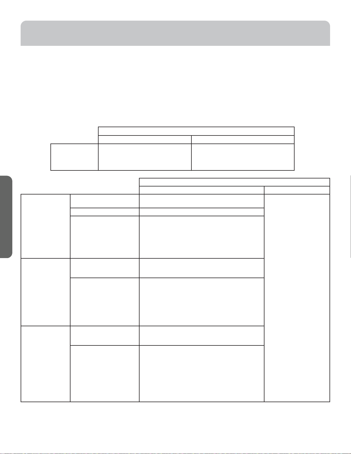
2-Function Wall Switch Settings
For 2-function wall switch setup:
• The humidity sensor and the low air flow setting must be
directly connected to line voltage. To deactivate these
features, set the selector switch to off position on the unit.
• Switch 1 is used to operate Fan as per Toggle Switch
setting and activate Delay OFF Timer.
• Switch 2 is used to operate light independently from the fan.
Tables describe fan functionality when switch 1 is turned on
or off.
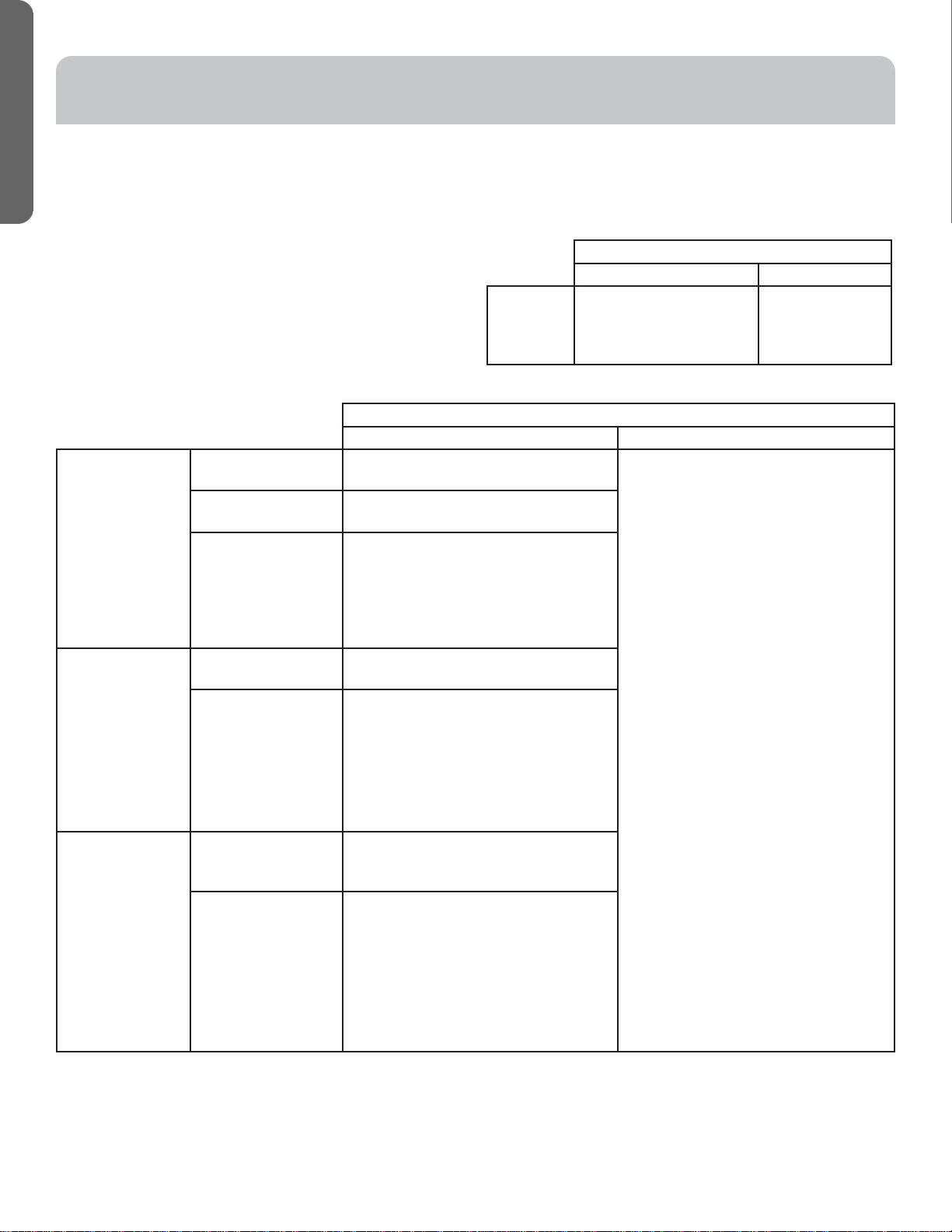
Wall Switch Setting
Switch 1 OFF Switch 1 ON
Toggle
Switch
Settings
Fan will stay OFF unless
humidity sensor or low air
flow setting is activated.
Fan will operate
at the set CFM as
per toggle switch
settings.
49-7000175 Rev. 3 7
ENGLISH
USING THE EXHAUST FAN
OPERATION (Cont.)
Wall Switch Setting
Switch 1 ON and 2 OFF Switch 1 ON and 2 ON
Low airflow
setting selector
(S)
OFF (Factory set to
OFF)
Fan will stay OFF unless humidity
sensor is activated.
Fan will operate at the set CFM as per
toggle switch setting.
30 CFM Fan will operate continuously at 30
CFM.
60% - Max% Fan will operate continuously at the
percentage of set CFM as per the
toggle switch setting. Example: If low
air flow selector is set to 60% and
toggle switch is set to 110 CFM, the fan
will operate at 66 CFM.
Humidity Sensor
selector (H)
OFF (Factory set to
OFF)
Fan will stay OFF unless low air flow
setting is activated.
30%-80% If the ambient humidity is below the
setting, the fan will stay OFF unless low
air flow setting is activated.
If the ambient humidity exceeds the
chosen RH%, the fan will operate at
high speed as per the set CFM toggle
switch setting
Time Delay
selector (T)
OFF (Factory set to
OFF)
Fan will stay OFF unless humidity
sensor or low air flow setting is
activated.
5-60 minutes When wall switch2 is turned OFF or
the humidity level drops below the
humidity sensor setting, the fan will
continue to run until the selected delay
time elapses.
**The fan will switch to the Low Air
Flow selector setting (if set), after the
selected delay time elapses.
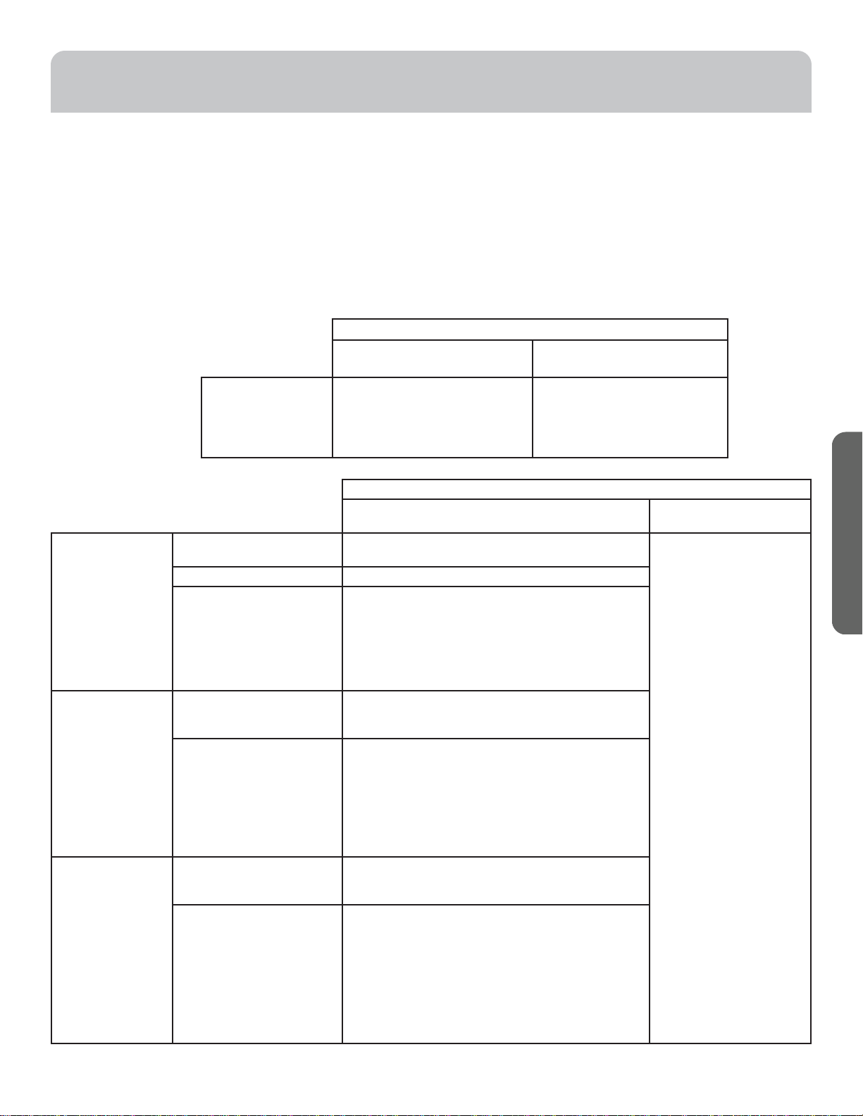
3-Function Wall Switch Settings
For 3-function wall switch setup:
• Switch 1 is used to deactivate all fan functions from the wall
switch. Switch 1 must always stay on to activate the low air
flow setting, humidity sensor and delay off timer.
• Switch 2 is used to override the humidity sensor and low air
flow setting and run fan as per the toggle switch setting.
• Switch 3 is used to operate light independently from the fan
Tables describe fan functionality when switch 2 is turned on
or off.
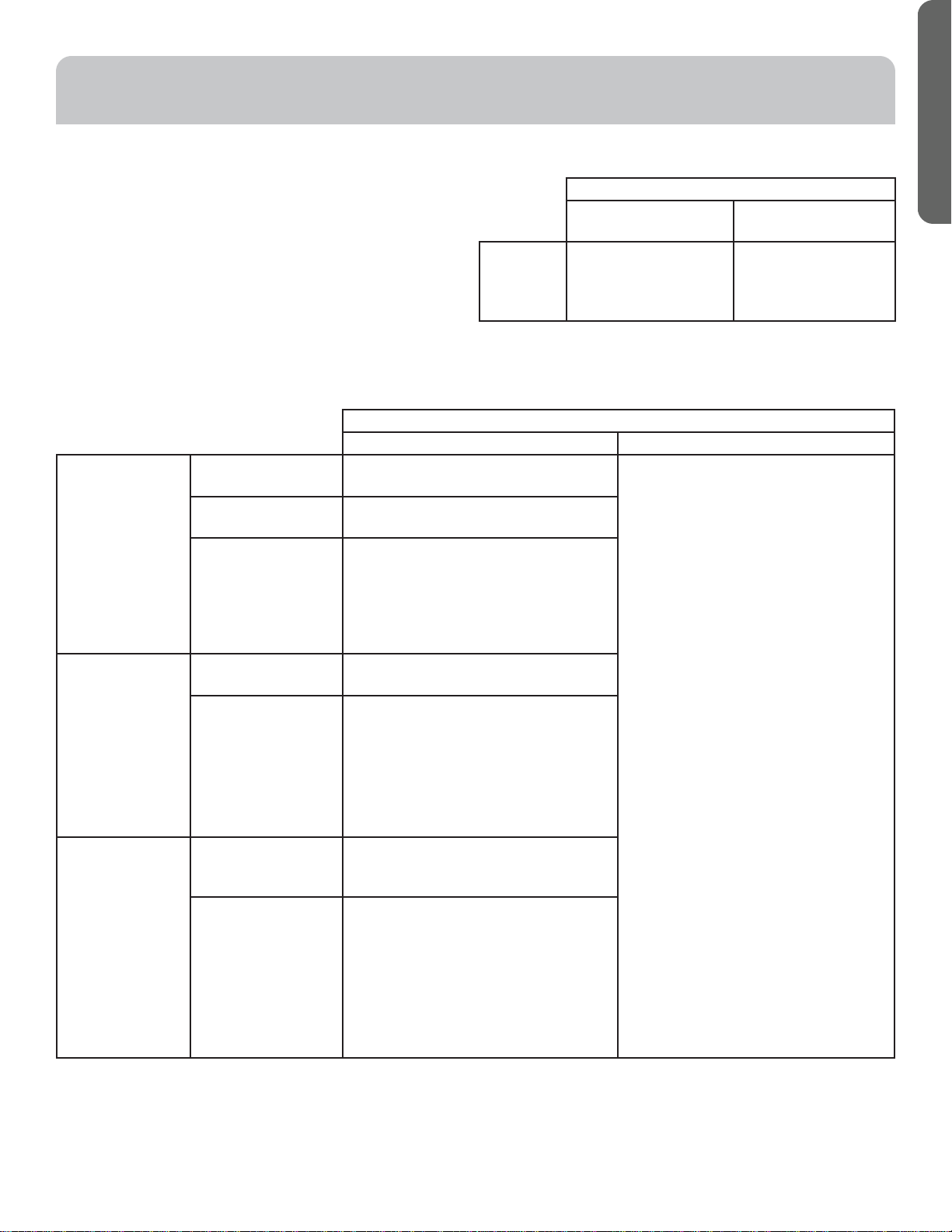
Wall Switch Setting
Switch 1 ON and
2 OFF
Switch 1 ON and
2 ON
Toggle
Switch
Settings
Fan will stay OFF
unless humidity sensor
or low air flow setting
is activated.
Fan will operate at the
set CFM as per toggle
switch settings.
8 49-7000175 Rev. 3
ENGLISH
INSTALLATION INSTRUCTIONS
BEFORE YOU BEGIN
Read these instructions completely and carefully.
•
IMPORTANT — Save these instructions for local
inspector’s use.
•
IMPORTANT — Observe all governing codes
and ordinances.
• Note to Installer – Be sure to leave these instructions with
the Consumer.
• Note to Consumer – Keep these instructions for future
reference.
• Skill level – Installation of this exhaust fan requires basic
mechanical skills.
• Proper installation is the responsibility of the installer.
• Product failure due to improper installation is not covered
under the Warranty.
WARNING
TO REDUCE THE RISK OF FIRE,
ELECTRIC SHOCK OR INJURY TO PERSONS,
OBSERVE THE FOLLOWING:
A. Installation work and electrical wiring must be
done by qualified person(s) in accordance with all
applicable codes and standards, including fire-rated
construction.
B. Sufficient air is needed for proper combustion and
exhausting of gases through the flue (chimney) of fuel
burning equipment to prevent back drafting. Follow
the heating equipment manufacturer’s guidelines
and safety standards such as those published by
the National Fire Protection Association (NFPA), the
American Society for Heating, Refrigeration and Air
Conditioning Engineers (ASHRAE) and the local code
authorities.
C. When cutting or drilling into wall or ceiling, do not
damage electrical wiring and other hidden utilities.
D. Ducted fans must always be vented to the outdoors.
E. If this unit is to be installed over a tub or shower, it
must be marked as appropriate for the application
and be connected to a GFCI (Ground Fault Circuit
Interrupter)-protected branch circuit.
F. Do not mount this product in a wall.
G. Never place a switch where it can be reached from a
tub or shower.
H. Install fan at least 2.1 meters (7 feet) above the floor.
I. This unit must be grounded
J. Not for use in kitchens.
K. Before beginning the installation, switch power off
at service panel and lock the service disconnecting
means to prevent power from being switched on
accidentally. When the service disconnecting means
cannot be locked, securely fasten a prominent
warning device, such as a tag, to the service panel.
PRODUCT CARE
Verify that power is turned off at the source before cleaning.
For quiet and efficient operation, long life, and attractive appearance - lower or remove grille and vacuum interior of unit with
the dusting brush attachment.
The motor is permanently lubricated and never needs oiling. If the motor bearings are making excessive or unusual noises,
replace the motor with the exact service motor. The impeller should also be replaced.
49-7000175 Rev. 3 9
ENGLISH
INSTALLATION PREPARATION
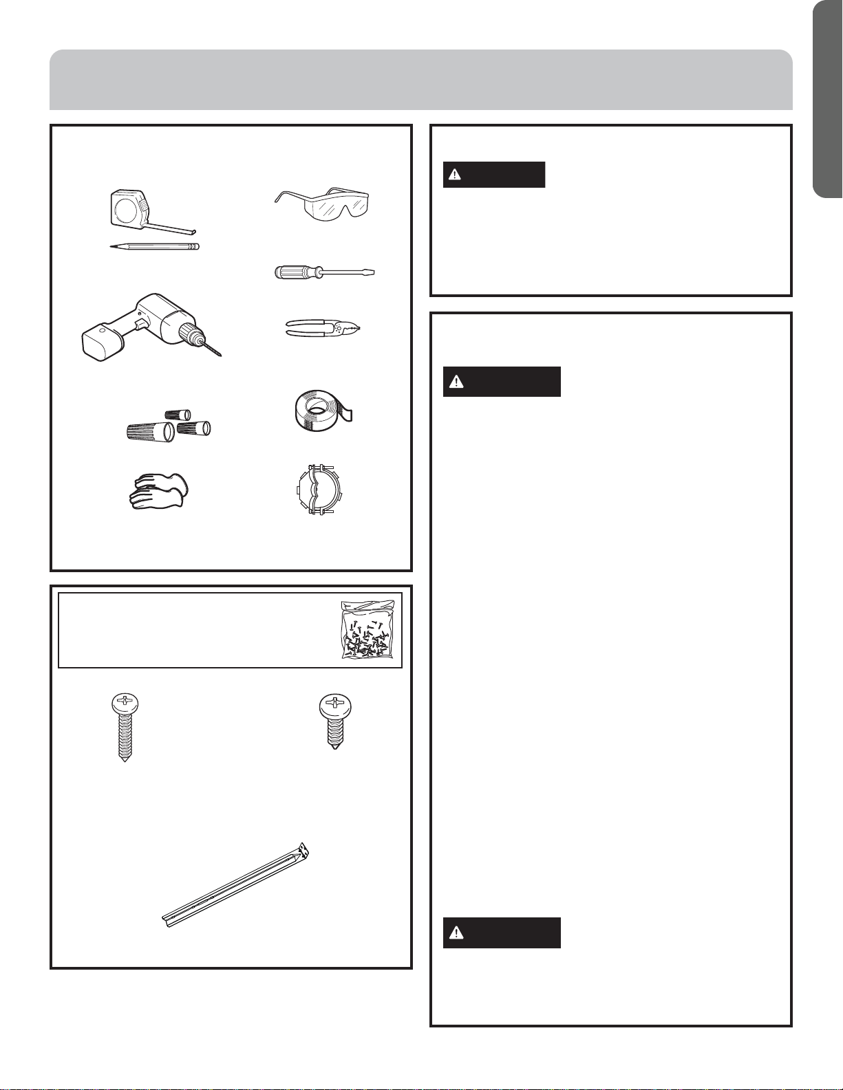
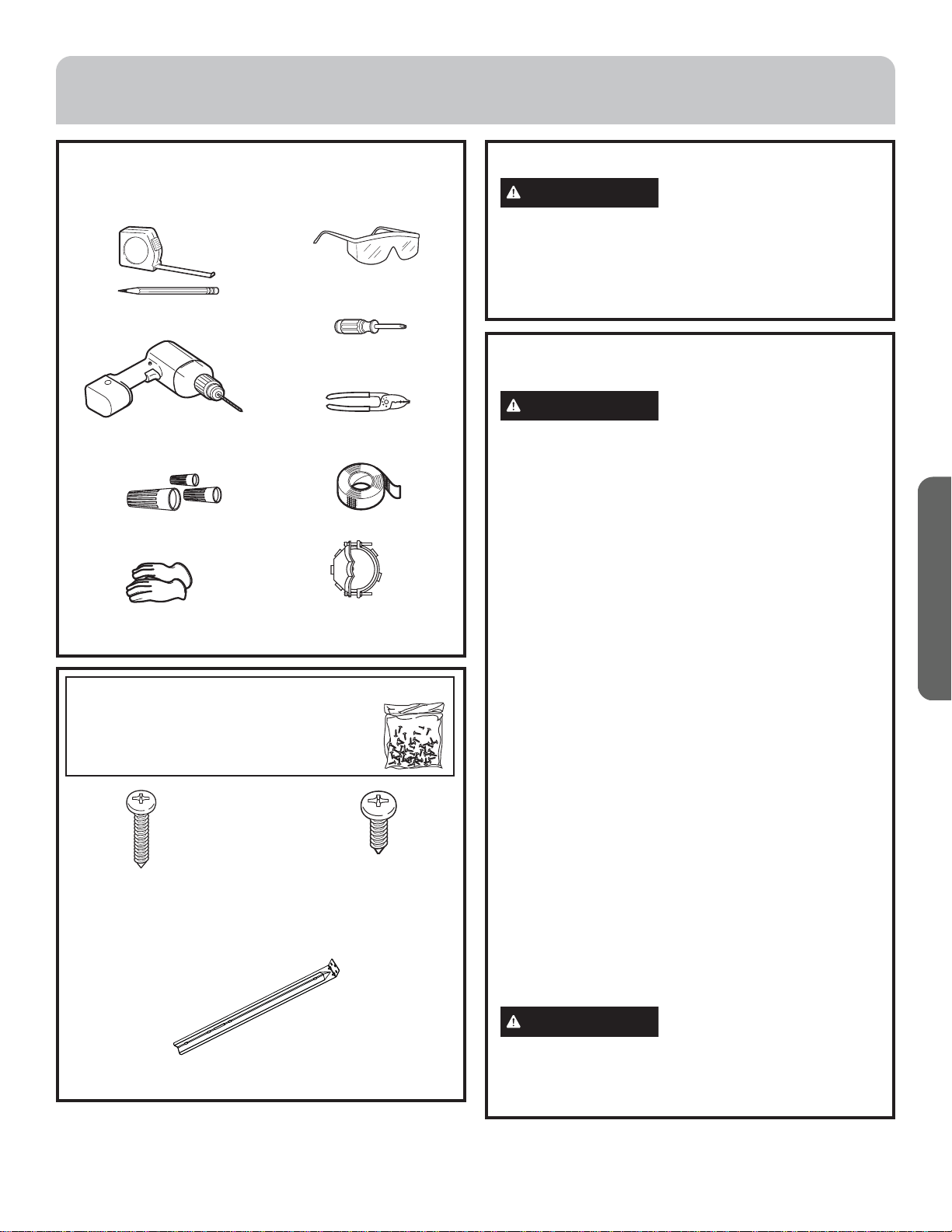
TOOLS AND MATERIALS REQUIRED
(NOT SUPPLIED)
Wire cutter/stripper
Duct tape
Safety glasses
Screwdriver
Strain relief for
junction box, 3/4”
diameter knockout
UL listed wire nuts
Pencil and tape measure
Gloves
REMOVE THE PACKAGING
CAUTION
Wear gloves to protect against sharp
edges.
• Remove and properly discard the plastic bag and other
packaging materials.
• Consider recycling options for your appliance
packaging material.
POWER SUPPLY
IMPORTANT – (Please read carefully)
WARNING
FOR PERSONAL SAFETY, THIS
APPLIANCE MUST BE PROPERLY GROUNDED.
Remove house fuse or open circuit breaker before
beginning installation.
Do not use an extension cord or adapter plug with this
appliance. Follow National Electrical Codes or prevailing
local codes and ordinances.
Electrical supply
These exhaust fans must be supplied with 120V, 60Hz,
and connected to a properly grounded branch circuit,
and protected by a 15 or 20 amp circuit breaker or time
delay fuse.
• Acceptable for use over a tub or shower when
connected to a GFCI (Ground Fault Circuit Interrupter)
- protected branch circuit.
• Never place a switch where it can be reached from a
tub or shower.
• Wiring must be 2 wire with ground.
• If the electrical supply does not meet the above
requirements, call a licensed electrician before
proceeding.
• Route house wiring as close to the installation location
as possible in the ceiling or wall.
• Connect the wiring to the house wiring in accordance
with local codes.
Grounding instructions
The grounding conductor must be connected to
a ground metal, permanent wiring system, or an
equipment-grounding terminal or lead on the hood.
WARNING
The improper connection of the
equipment-grounding conductor can result in a risk
of electric shock. Check with a qualified electrician or
service representative if you are in doubt whether the
appliance is properly grounded.
Electric drill with #2 Phillips
drill bit
HARDWARE PACKAGE (supplied)
Locate and check contents.
A. 1" screw (QTY: 4)
Used for hanger bar
installation to joist
(QTY: 4) Hanger Bar for mounting fan
B. 1/2" screw (QTY: 2)
Used for securing hanger
bars together
10 49-7000175 Rev. 3
ENGLISH
INSTALLATION
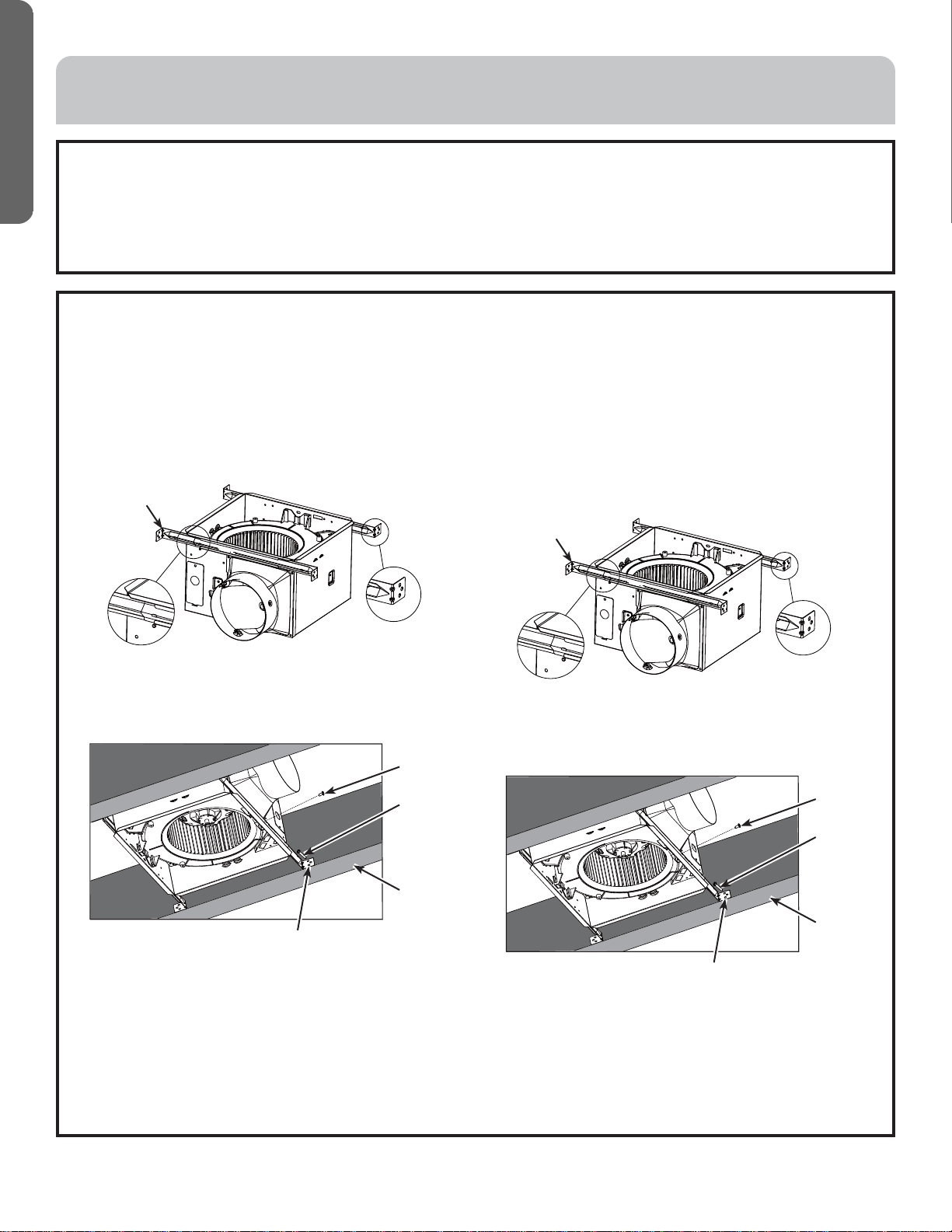
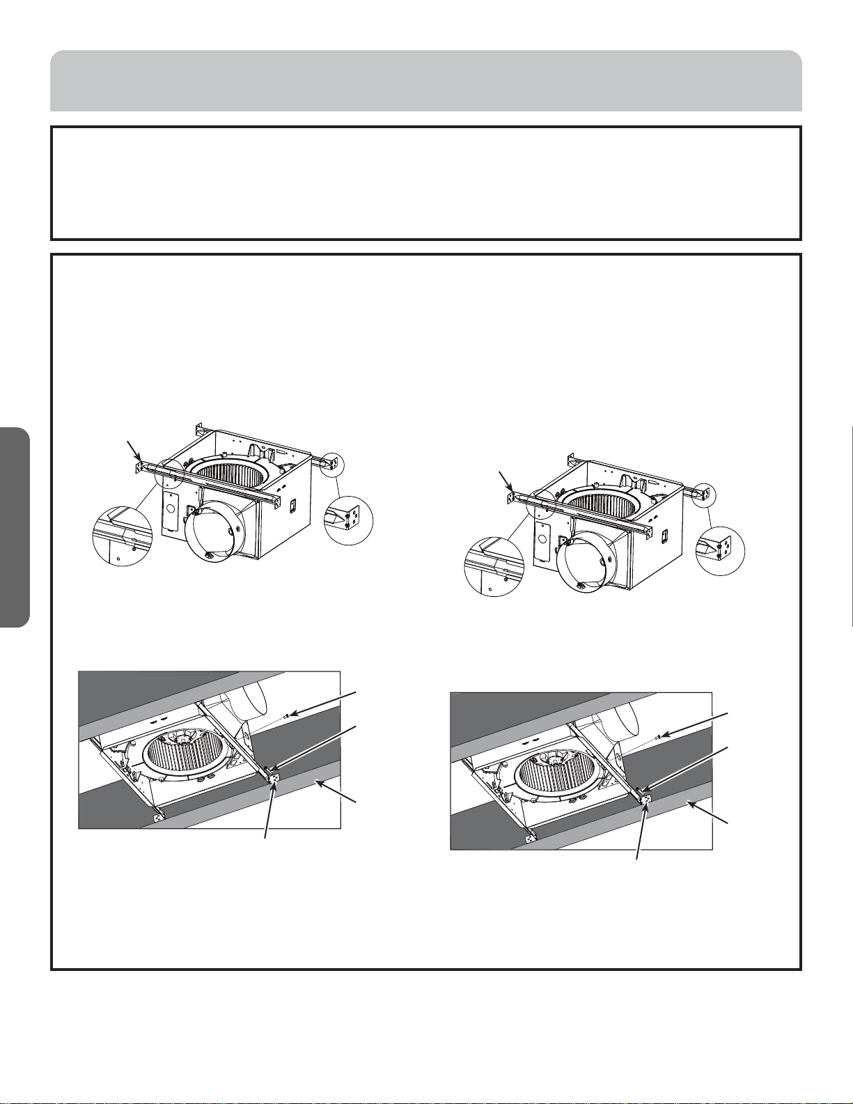
STEP 1. INSTALL HOUSING
IMPORTANT: This product can only be mounted to a
ceiling.
A. NEW CONSTRUCTION INSTALLATION: Mount with
hanger bars provided; they allow the housing to be
positioned accurately anywhere between the framing.
The hanger bars span up to 24" and are compatible with
all types of framing.
Slide hanger bar into the housing channel, extending
it to fit between the framing. Place the housing so
that the hanger bar tabs are in contact with the joist as
shown in image below.
Screw the hanger bars to the joist using screw (A)
through one of the holes on each end tab of the hanger
bar. Secure the hanger bars together using screw (B) by
screwing them together through the aligned slots.
B. INSTALLATION IN EXISTING CEILING: Must have
access to area above the ceiling for this installation.
With a pencil, trace an outline of the housing onto the
ceiling; the cardboard protective cover can be used as
a template for the ceiling cut out. Set the housing aside
and cut out an opening for the fan.
Mount using hanger bars provided. The hanger bars
span up to 24" and are compatible with all types of
framing.
Slide hanger bar into the housing channel, extending it
to fit between the framing. Place the housing so that
the hanger bar tabs are in contact with the bottom of
the joist.
Screw the hanger bars to the joist using an screw (A)
through one of the holes on each end tab of the hanger
bars. Secure the hanger bars together screwing them
trough an available aligned slots with a screw (B).
LOCATION
Choose your exhaust fan location and plan the duct route to vent exhaust to the outdoors. To maximize the ventilation
performance, the following is recommended:
a. Minimize the duct run length and number of transitions and elbows.
b. Maintain a constant duct size and minimize the length of flexible ducting used.
Hanger Bar
Hanger Bar
Screw B
Joist
Hanger Bar Tab
Screw A
Screw B
Joist
Hanger Bar Tab
Screw A
49-7000175 Rev. 3 11
ENGLISH
INSTALLATION
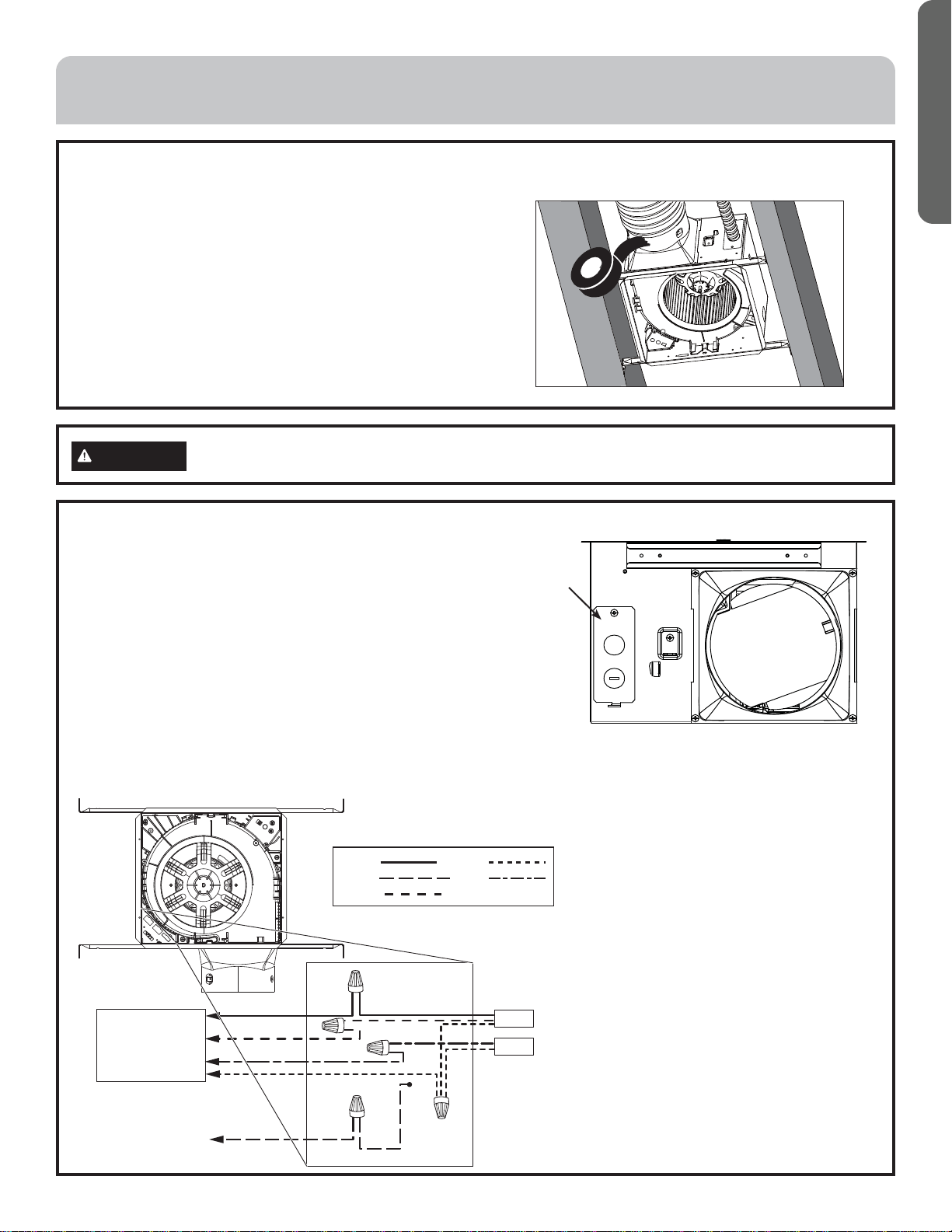
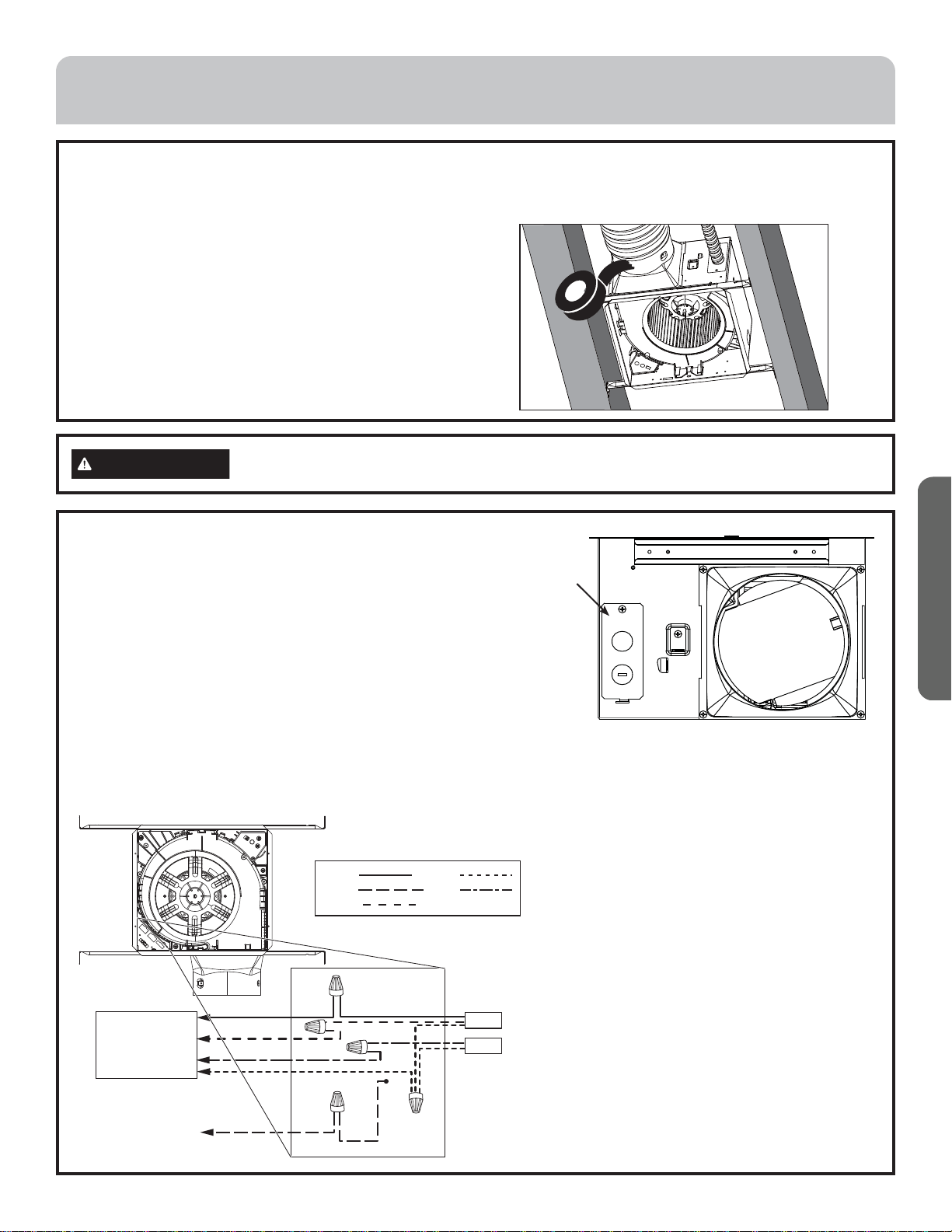
STEP 2. CONNECT DUCTWORK
• This exhaust fan has a 6” exhaust damper. Connect
house ducting to the exhaust damper and seal all
connections with duct tape. Run the ductwork to a
roof or wall cap. Ensure that the exhaust damper flap
functions freely.
NOTE: The ducting from this fan to the outside of building
has a strong effect on the air flow, noise and energy use of
the fan. Use the shortest, straightest duct routing possible
for best performance, and avoid installing the fan with
smaller ducts than recommended. Insulation around the
ducts can reduce energy loss and inhibit mold growth.
Fans installed with existing ducts may not achieve their
rated air flow.
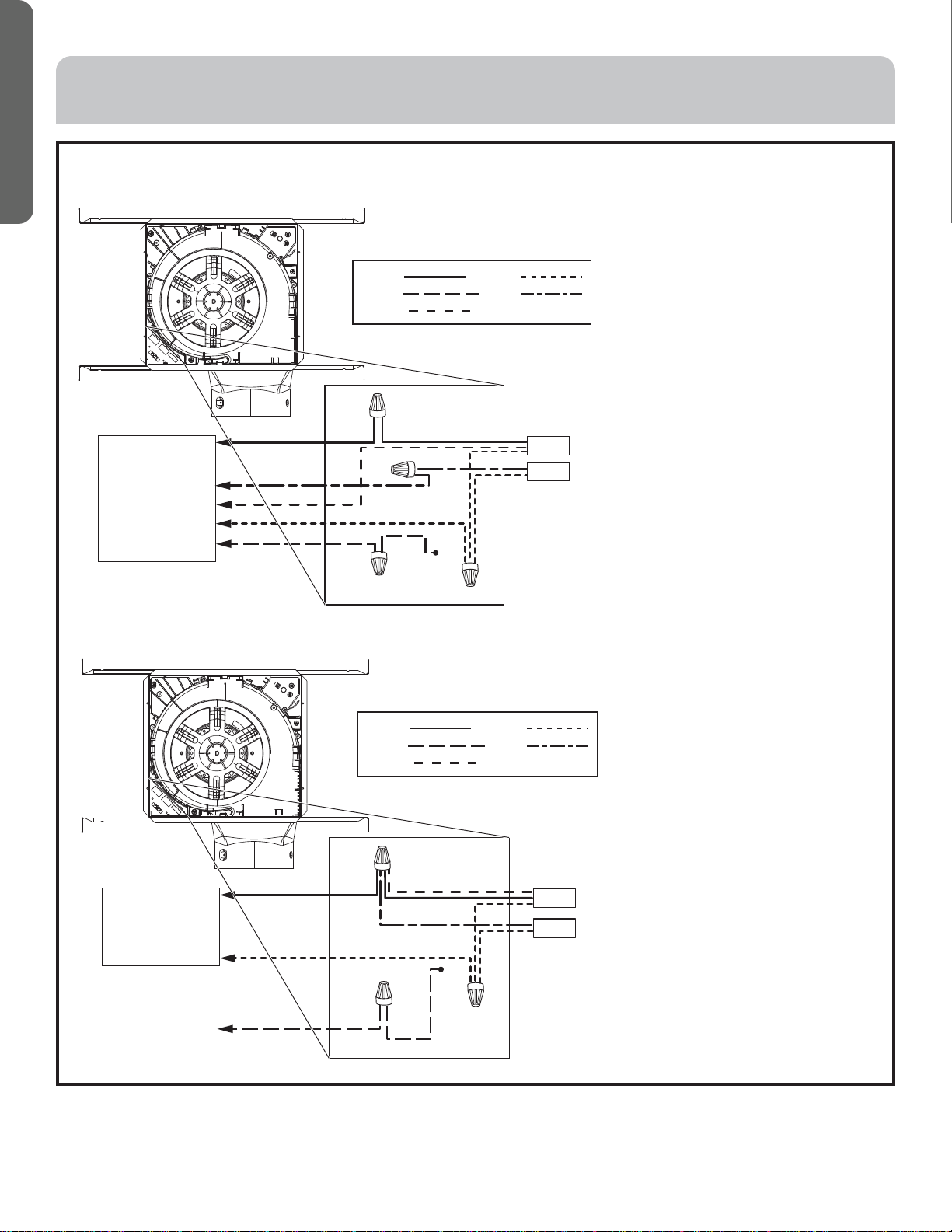
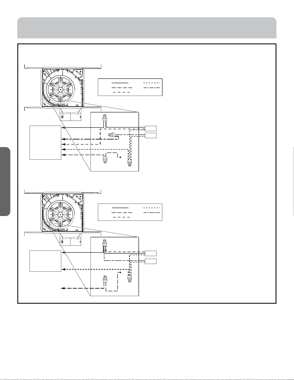
STEP 3. CONNECT ELECTRICAL
Verify that power is turned off at the source. Remove
knockout bracket and install strain relief on the open
knockout. The knockout bracket can be flipped upside
down if needed to have open knockout at the top or
bottom.
Connect black wire to black house wire, white wire to white
house wire, and green wire to green house wire using
UL approved wire nuts. All electrical connections must
be made inside the unit. Refer to the wiring diagrams for
connection to wall switch.
Secure the knockout bracket in place using the screw
provided.
Knockout
Bracket
WARNING
Disconnect all electrical power at the main circuit breaker or fuse box before installing.
Connection to three function wall switch
LIGHT
FA N
SWITCH 3
SWITCH 1
SWITCH 2 BLK
BRW
BLU
WHT
GRN
NEUTRAL
GROUND
BLACK
GREEN
WHITE
BLUE
BROWN
POWER SUPPLY
AC 120 V 60 Hz
12 49-7000175 Rev. 3
ENGLISH
INSTALLATION
STEP 3. CONNECT ELECTRICAL (Cont.)
Connection to two function wall switch
Connection to single wall switch
LIGHT
FA N
BLACK
GREEN
WHITE
BLUE
BROWN
POWER SUPPLY
AC 120 V 60 Hz
120 V LINE
NEUTRAL
GROUND
SWITCH 1
SWITCH 2
BLK
BLU
WHT
GRN
BRW
LIGHT
FA N
NEUTRAL
GROUND
BLACK
GREEN
WHITE
BLUE
BROWN
POWER SUPPLY
AC 120 V 60 Hz
SWITCH 1
BLK
BLU
GRN
BRW
WHT
49-7000175 Rev. 3 13
ENGLISH
STEP 3. CONNECT ELECTRICAL
(Cont.)
WARNING
If house wiring is not 2-wire with a
ground wire, a ground must be provided by the installer.
When house wiring is aluminum, be sure to use UL
approved anti-oxidant compound and aluminum-to-
copper connectors.
Push all the wiring into the unit and install the wire cover
by pushing the edge under the tab in the housing and
secure it in place with a screw. Ensure wires are not
pinched.
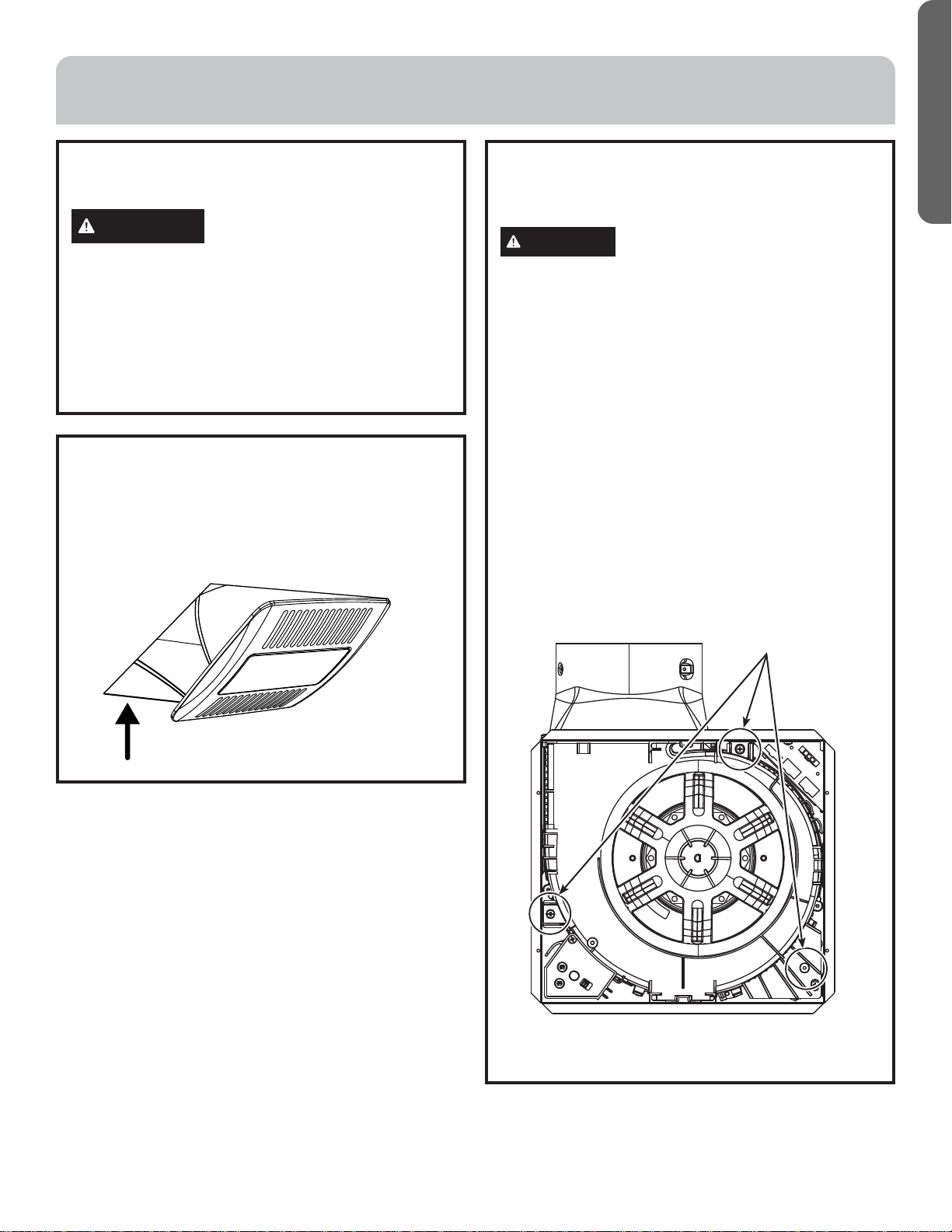
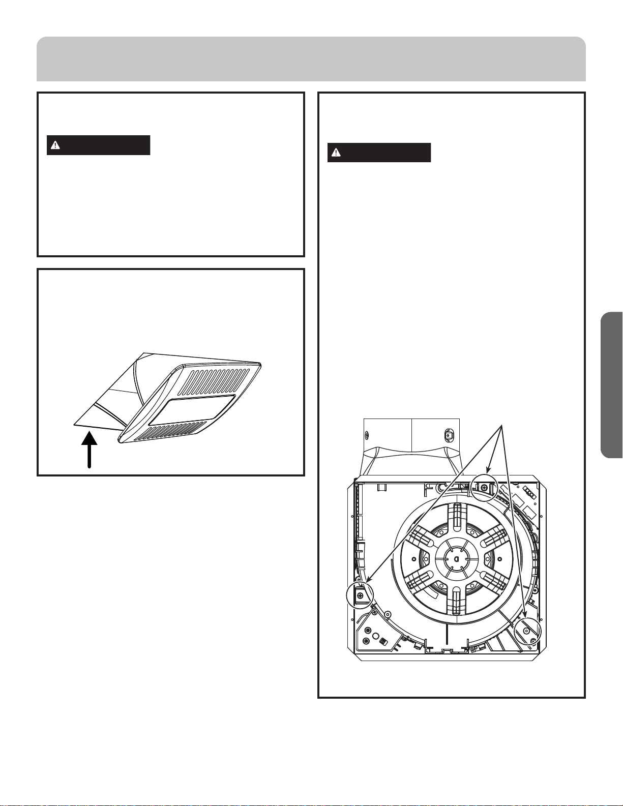
INSTALLATION
STEP 4. INSTALL GRILLE
Connect the light connector from the grille to the
wire plate. Press the springs on the sides of the grille
together and insert them into the slots in the motor
assembly. Firmly push the attached grille up against the
ceiling.
PRODUCT REPLACEMENT
In case of Haier product replacement, follow the steps
below to replace unit:
WARNING
Disconnect all electrical power at the
main circuit breaker or fuse box before installing.
1. Remove the grille from existing unit.
2. Unplug the motor and the light connectors from the
wiring plate of the current unit. Uninstall the motor
assembly by removing the screws and pulling it out of
the housing.
3. Discard the motor assembly.
4. Unbox new unit and follow step 2 of Product
Replacement section to remove motor assembly and
light grill from new unit.
5. Unbox new unit and unplug the motor connector
from the wiring plate and uninstall the motor and
control assembly by removing the three screws
highlighted in the figure below and pulling it up from
the housing.
6. Insert the new motor assembly into the existing
housing and secure using the screws as shown below.
Connect the motor connector to the wiring plate.
7. Connect the light connector and reinstall the grille,
turn power on to test unit.
Screws
14 49-7000175 Rev. 3
ENGLISH
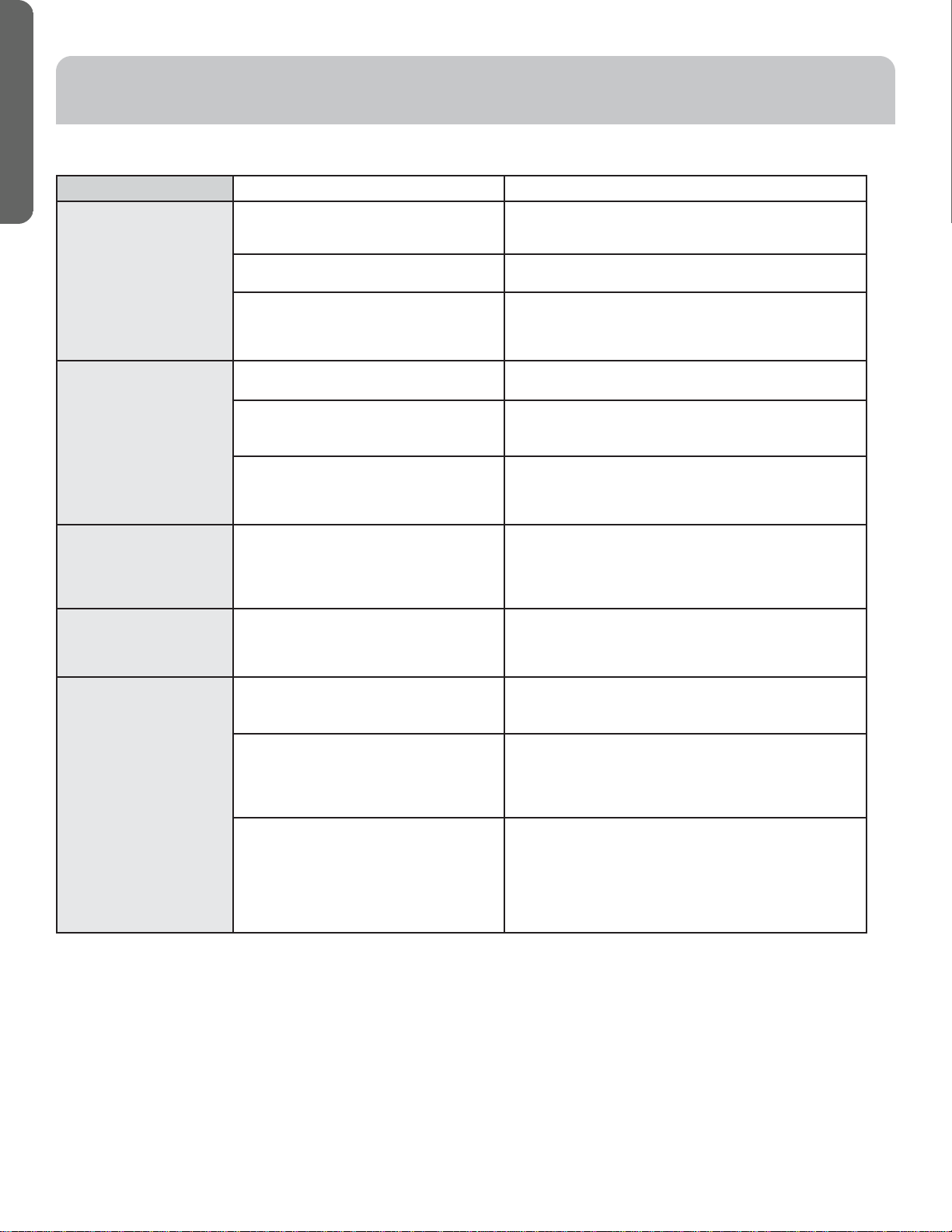
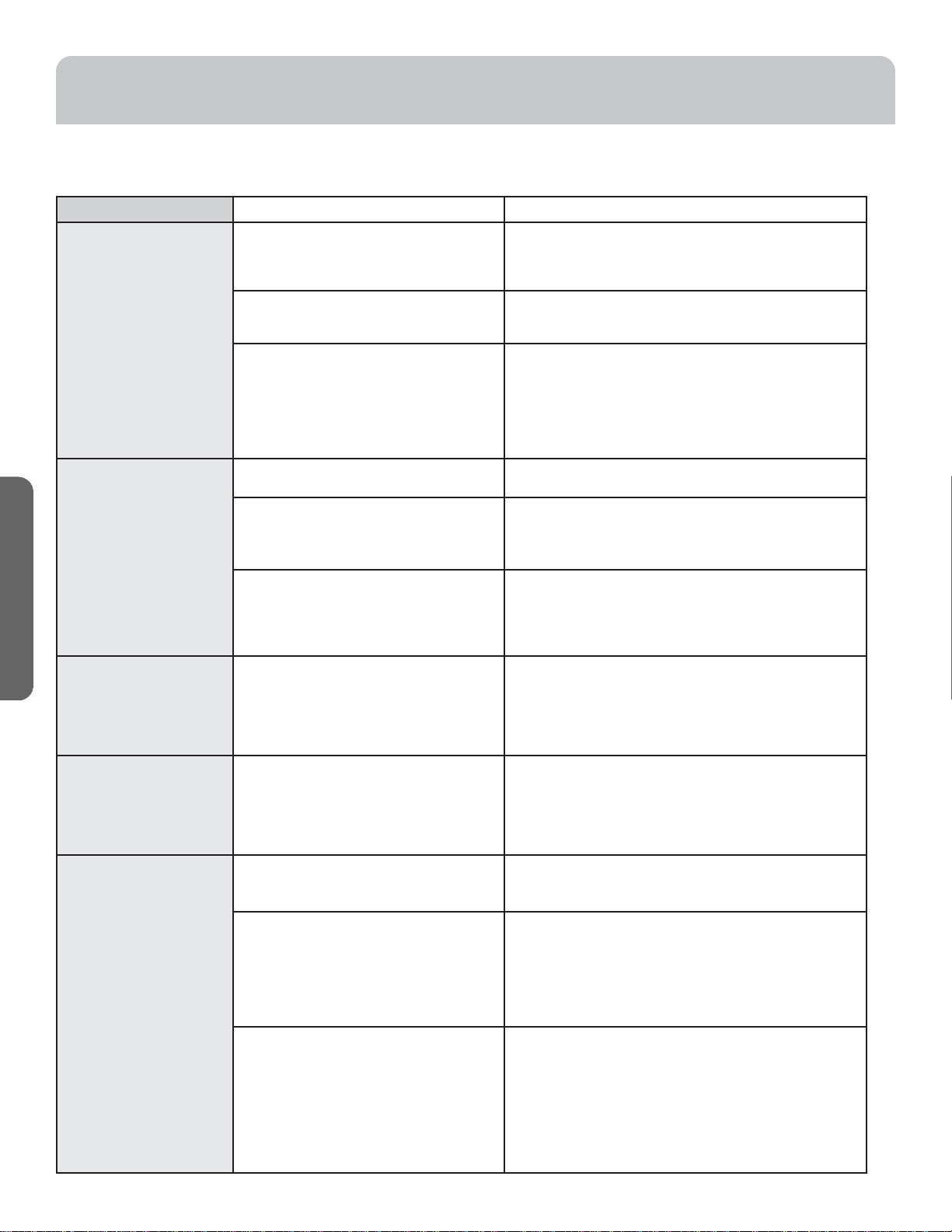
TROUBLESHOOTING TIPS
Save time and money! Review the chart below first and you may not need to schedule service.
Problem Possible Cause What To Do
Fan/light does not
operate when switch is
turned on
A GFCI or circuit breaker is tripped, or
house fuse may be blown.
Reset GFCI, circuit breaker or replace house fuse. If
this does not fix the issue, please refer to the LIMITED
WARRANTY section.
It may seem that the fan is not running if
low air flow setting is activated.
Confirm fan is running by looking into the grill.
For three function wall switch setup,
switch one is off.
Refer to page 7 for three function wall switch settings
and page 11 for three function wiring diagram. For three
functioin wall switch wiring setup, switch 1 must always
stay on for fan operation.
Fan fails to circulate air
or moves air slower than
normal and/or fan is
making loud or abnormal
airflow noise
Obstructions in duct work. Make sure that if your wall or roof cap has a blade or door
that it is open.
Damper flap on the product may not be
open
Make sure damper swings freely. Damper flap may flip
over and will not fully open when this happens. Adjust to
original position.
Wrong duct size used in installation. This fan requires 6” ducting to perform optimally. Using
smaller duct size will cause reduced venting. Minimize
the duct run length and number of transitions and
elbows.
Motor bearings are
making excessive or
unusual noises.
Obstruction in the motor housing or bearing
failure.
Check for obstructions in the motor housing, refer to the
PRODUCT CARE section for cleaning instructions. The
motor is permanently lubricated and never needs oiling.
If the issue in not fixed, please refer to the LIMITED
WARRANTY section.
When the wall switch
is turned on, there is a
slight delay before the
fan and light turn on.
It is normal for the fan and light to take a few seconds to
start running once wall switch is turned on.
Fan keeps running when
the wall switch is turned
off.
Low air flow setting is activated. To deactivate this feature, set the low air flow selector
setting to off position on the unit
Delay Off timer is activated. The unit will continue to run for the set delay off time once
the wall switch for fan is turned off or the humidity level
drops below the humidity sensor setting. To deactivate this
feature, set the delay off timer selector to off position on
the unit.
Humidity sensor is activated. The humidity sensor will keep the fan running until the
relative humidity level drops below the set percent on
the humidity sensor. If the fan continuously responds to
changing environmental conditions (too sensitive), the
humidity sensor setting may need to be adjusted. To
deactivate the feature set the Humidity selector to off
position on the unit.
49-7000175 Rev. 3 15
ENGLISH
Haierappliances.com
For a warranty claim please call Haier at 888-384-3641. Please have your Model and Serial number available. Additionally, proof of
òõìêìñäïóøõæëäöèçä÷èìöñèèçèç÷òðäîèäúäõõäñ÷üæïäìð
What Haier will not cover:
• Failure of the product if it is abused, misused, modified,
or used for other than the intended purpose or used
commercially.
• Replacement of house fuses or resetting of circuit
breakers.
• Damage caused after delivery.
• Damage to the product caused by accident, fire, floods, or
acts of God.
• Incidental or consequential damage caused by possible
defects with this appliance.
EXCLUSION OF IMPLIED WARRANTIES
Your sole and exclusive remedy is product repair as provided in this Limited Warranty. Any implied warranties, including
the implied warranties of merchantability or fitness for a particular purpose, are limited to one year or the shortest period
allowed by law.
For sale in the 50 United States and the District of Columbia only:
For US Customers: This limited warranty is extended to the original purchaser for products purchased for home use within the
USA.
Some states do not allow the exclusion or limitation of incidental or consequential damages. This limited warranty gives you
specific legal rights, and you may also have other rights which vary from state to state. To know what your legal rights are,
consult your local or state consumer affairs office or your state’s Attorney General.
Warrantor: GE Appliances, a Haier company
Louisville, KY 40225
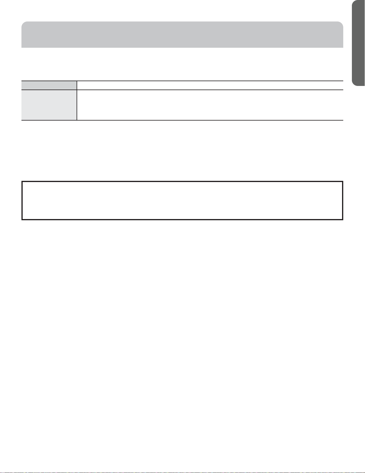
For the period of Haier will replace
One year
From the date
of the original
purchase
If the exhaust fan fails due to a defect in materials or workmanship, during this limited one-year
warranty, Haier will either repair your product or replace your product with a new or remanufactured
product, or refund the purchase price of the product at Haier's sole discretion.
LIMITED WARRANTY

16 49-7000175 Rev. 3
ENGLISH
IMPORTANT
Do Not Return This Product To The Store
If you have a problem with this product, please call 888.384.3641 for the name and telephone number of the nearest
authorized service center.
DATED PROOF OF PURCHASE REQUIRED FOR WARRANTY SERVICE
Printed in China

Manual del Propietario
e Instrucciones de Instalación
QVE110DTWW
Extractor con CFM Ajustable
49-7000175 Rev. 3 02-22 GEA


49-7000175 Rev. 3 3
ESPAÑOL
ÍNDICE
SEGURIDAD DEL REFRIGERADOR ..................................................................................4
USO DEL EXTRACTOR ............................................................................................5
CUIDADO DEL PRODUCTO ........................................................................................8
NSTRUCCIONES DE INSTALACIÓN .................................................................................8
SOLUCIÓN DE PROBLEMAS .......................................................................................14
GARANTÍA LIMITADA ............................................................................................ 15
INFORMACIÓN A TENER EN CUENTA
Le agradecemos la compra de este producto de marca Haier. Este
manual del propietario le ayudará a lograr el mejor rendimiento de su
nuevo extractor.
Para referencia futura, registre el modelo y número de serie ubicados
en una etiqueta dentro de la carcasa.
Engrape la prueba de compra a este manual para asistirle cuando
necesite obtener servicio bajo la garantía.
__________________________________________________________
Número de modelo
__________________________________________________________
Número de serie
__________________________________________________________
Fecha de compra
SITIO WEB DE HAIER
¿Desea realizar una consulta o necesita ayuda con su electrodoméstico? ¡Intente a través del Sitio Web de Haier las 24 horas del día,
cualquier día del año! Usted también puede comprar más electrodomésticos maravillosos de Haier y aprovechar todos nuestros servicios
de soporte a través de Internet, diseñados para su conveniencia. En EE.UU.: Haierappliances.com
Registre su Electrodoméstico
¡Registre su electrodoméstico nuevo a través de Internet, según su conveniencia! Un registro puntual de su producto permitirá una mejor
comunicación y un servicio más puntual de acuerdo con los términos de su garantía, en caso de surgir la necesidad.
• Escanee el Código QR en la tarjeta de registro del producto, o en el producto.
NOTA: Esto es sólo un ejemplo de lo que representa un código QR.
• O visite Haierappliances.com
• O envíe por correo su tarjeta de registro preimpresa, incluida en el material de embalaje.
4 49-7000175 Rev. 3
ESPAÑOL
LEA Y GUARDE ESTAS INSTRUCCIONES
ADVERTENCIA
PARA REDUCIR EL RIESGO DE
INCENDIO, DESCARGA ELÉCTRICA O LESIONES A PERSONAS,
CUMPLA CON LOS SIGUIENTES PUNTOS:
A. Utilice esta unidad sólo de la manera concebida por el
fabricante. Si tiene alguna pregunta, comuníquese con el
fabricante.
B. Antes de realizar reparaciones o limpiar la unidad, desconecte
la energía del panel de servicio y bloquee los medios de
desconexión para evitar el accionamiento de la energía de
manera accidental. Cuando los medios de desconexión de
servicio no pueden bloquearse, coloque sobre el panel de
servicio un dispositivo de advertencia bien visible, como una
etiqueta.
C. Esta unidad debe estar conectada a tierra.
D. No use este extractor con ningún dispositivo de control de
velocidad de estado sólido.
PRECAUCIÓN
SÓLO PARA USO DE VENTILACIÓN
GENERAL. NO LO UTILICE PARA ELIMINAR MATERIALES Y
VAPORES PELIGROSOS O EXPLOSIVOS.
E. Para más información y para conocer sobre los requisitos, por
favor lea la etiqueta de especificaciones del producto.
FORMA ADECUADA DE DESCARTAR SU ELECTRODOMÉSTICO
Descarte o recicle su producto de acuerdo con las Regulaciones Federales y Locales. Comuníquese con las autoridades locales para
descartar o reciclar su producto de forma ambiental mente segura.
INFORMACIÓN IMPORTANTE DE SEGURIDAD
LEA TODAS LAS INSTRUCCIONES ANTES DE USAR ESTE ELECTRODOMÉSTICO
INFORMACIÓN DE SEGURIDAD
49-7000175 Rev. 3 5
ESPAÑOL
USO DEL EXTRACTOR
FUNCIONAMIENTO
NOTA: Asegúrese de que todos los interruptores de pared estén en
la posición OFF (Apagado) antes de realizar cualquier modificación
sobre el control.
Este extractor posee las siguientes funciones para conveniencia del
cliente:
• Interruptor de Palanca para Ajuste de CFM: Los usuarios podrán
configurar el extractor en 80, 110 o 140 CFM, ajustando las
posiciones 1 y 2 del interruptor de palanca, de acuerdo con la
ilustración. El extractor está configurado de fabrica en 110 CFM.
• Selector del Sensor de Humedad (H): Cuando el % de humedad
relativa supere la configuración del sensor de humedad ajustada,
el extractor funcionará en la configuración de CFM seleccionada.
Si el extractor responde de forma continua a las condiciones
cambiantes del ambiente (demasiado sensible), es posible que
sea necesario ajustar la configuración del sensor de humedad. La
posición configurada de fábrica es OFF (Apagado).
• Selector de Configuración de Circulación de Aire Bajo (S): Los
usuarios podrán configurar la ventilación continua con circulación
de aire baja del extractor a 30 CFM o en un porcentaje de CFM del
interruptor de palanca configurado
La posición configurada de
fábrica es OFF (Apagado).
• Selector del Temporizador de Retraso (T): Configura la cantidad
de tiempo que el extractor continuará funcionando de acuerdo
con la configuración del interruptor de palanca, una vez que el
interruptor de pared se encuentre en OFF (Apagado). Si el sensor
de humedad se encuentra configurado, el extractor continuará
funcionando durante el tiempo de retraso seleccionado una
vez que la humedad del ambiente descienda por debajo de la
configuración del sensor de humedad. La posición configurada de
fábrica es OFF (Apagado).
La operatividad de estas funciones dependerá de la configuración
del cableado del interruptor de pared. Consulte la sección
CONECTE LA ELECTRICIDAD para acceder a los diagramas del
cableado de conexión del interruptor de pared.
Si los cableados del extractor y la luz fueron conectados en un único
interruptor de pared, sólo será activada la Función de Ajuste de CFM
del Interruptor de Palanca, y el extractor funcionará de acuerdo con
la configuración de CFM.
Consulte en las siguientes secciones para conocer la operatividad
del interruptor de pared de dos funciones o tres funciones.
NOTA: Es normal que el extractor tarde algunos segundos en
comenzar a funcionar una vez que el interruptor de pared sea
encendido.
T
H
OFF
30%
45%
60%
80%
60min
20min
40min
OFF
5min
S
OFF
Max.
60%
80%
30
CFM
Humidity
sensor select
o
Time delay Low airflow
selectorsetting
selector
Selector de
configuración
de circulación
de aire baja
Selector del
sensor de
humedad
Selector de
retraso del
temporizador
12 12 12
Toggle Switch
Switch
position
Airflow (CFM)
140 110 80
Interruptor
de Palanca
6 49-7000175 Rev. 3
ESPAÑOL
USO DEL EXTRACTOR
FUNCIONAMIENTO (Cont.)
Configuración del Interruptor de Pared
Interruptor 1 Apagado Interruptor 1 ENCENDIDO
Selector de
configuración de
circulación de aire
baja (S)
Apagado (Configuración de
Fábrica en Apagado)
El extractor permanecerá en OFF (Apagado) a menos
que se active el sensor de humedad.
El extractor funcionará
en los CFM configurados,
de acuerdo con las
configuraciones del
interruptor de palanca.
30 CFM El extractor funcionará de forma continua en 30 CFM.
60% - Max% El extractor funcionará de forma continua en el
porcentaje de CFM configurados, de acuerdo con
las configuraciones del interruptor de palanca. Por
ejemplo: si el selector de circulación de aire bajo se
configura en 60% y el interruptor con palanca se
configura en 110 CFM, el extractor funcionará en 66
CFM.
Selector del Sensor
de Humedad (H)
Apagado (Configuración de
Fábrica en Apagado)
El ventilador permanecerá en OFF (Apagado), a menos
que la configuración de circulación de aire baja sea
activada.
30%-80% Si la humedad del ambiente se encuentra por debajo
de la configuración elegida, el ventilador permanecerá
en OFF (Apagado) a menos que la configuración de
circulación de aire baja sea activada.
Si la humedad del ambiente supera el porcentaje de
humedad relativa (RH%), el extractor funcionará en
velocidad alta de acuerdo con la configuración de CFM
con el interruptor de palanca.
Selector de Retraso
del Temporizador
(T)
Apagado (Configuración de
Fábrica en Apagado)
El ventilador permanecerá en OFF (Apagado) a menos
que el sensor de humedad o la configuración de
circulación de aire baja sean activados.
5 – 60 minutos Cuando el interruptor de pared 1 se configure en OFF
(Apagado) o los niveles de humedad desciendan por
debajo de la configuración del sensor de humedad, , el
extractor continuará funcionando hasta que el tiempo
de retraso seleccionado haya transcurrido.
**El extractor pasará a la configuración del selector
de Circulación de Aire Bajo (si fue configurado), una
vez que el tiempo de retraso seleccionado haya
transcurrido.
Configuraciones del Interruptor de Pared de 2 Funciones
Para la configuración del interruptor de pared de 2 funciones:
• El sensor de humedad y la configuración de circulación de aire baja deberán estar conectados directamente al voltaje. A fin de desactivar
estas funciones, configure el interruptor de selección en la posición de apagado sobre la unidad.
• El Interruptor 1 se usa para operar la función Fan (Extractor), de acuerdo con la configuración de la función Toggle Switch (Interruptor de
Palanca), y activar Delay OFF Timer (Temporizador de Retraso Apagado).
• El Interruptor 2 se usa para operar la luz de forma independiente del extractor.
Las tablas describen la funcionalidad del extractor cuando el interruptor 1 es encendido o apagado.
Configuración del Interruptor de Pared
Interruptor 1 Apagado Interruptor 1 ENCENDIDO
Configuraciones
del Interruptor de
Palanca
El extractor permanecerá en OFF
(Apagado) a menos que el sensor
de humedad o la configuración de
circulación de aire baja sean activados.
El extractor funcionará en los CFM
configurados, de acuerdo con las
configuraciones del interruptor de palanca.
49-7000175 Rev. 3 7
ESPAÑOL
USO DEL EXTRACTOR
FUNCIONAMIENTO (Cont.)
Configuración del Interruptor de Pared
Interruptor 1 Encendido y 2 Apagado Interruptor 1 Encendido y
2 Apagado
Selector de
configuración de
circulación de aire
baja (S)
Apagado (Configuración de
Fábrica en Apagado)
El extractor permanecerá en OFF (Apagado) a menos
que se active el sensor de humedad.
El extractor funcionará
en los CFM configurados,
de acuerdo con las
configuraciones del
interruptor de palanca.
30 CFM El extractor funcionará de forma continua en 30 CFM.
60% - Max% El extractor funcionará de forma continua en el
porcentaje de CFM configurados, de acuerdo con
las configuraciones del interruptor de palanca. Por
ejemplo: si el selector de circulación de aire bajo se
configura en 60% y el interruptor con palanca se
configura en 110 CFM, el extractor funcionará en 66
CFM.
Selector del Sensor
de Humedad (H)
Apagado (Configuración de
Fábrica en Apagado)
El ventilador no permanecerá en OFF (Apagado), a
menos que la configuración de circulación de aire baja
sea activada.
30%-80% Si la humedad del ambiente se encuentra por debajo
de la configuración, el ventilador permanecerá en OFF
(Apagado) a menos que la configuración de circulación
de aire baja sea activada.
Si la humedad del ambiente supera el porcentaje de
humedad relativa (RH%), el extractor funcionará en
velocidad alta de acuerdo con la configuración de CFM
con el interruptor de palanca.
Selector de Retraso
del Temporizador
(T)
Apagado (Configuración de
Fábrica en Apagado)
El ventilador permanecerá en OFF (Apagado) a menos
que el sensor de humedad o la configuración de
circulación de aire baja sean activados.
5 – 60 minutos Cuando el interruptor de pared 2 se configure en OFF
(Apagado) o los niveles de humedad desciendan por
debajo de la configuración del sensor de humedad, el
extractor continuará funcionando hasta que el tiempo
de retraso seleccionado haya transcurrido.
**El extractor pasará a la configuración del selector
de Circulación de Aire Bajo (si fue configurado), una
vez que el tiempo de retraso seleccionado haya
transcurrido.
Configuraciones del Interruptor de Pared de 3 Funciones
Para la configuración del interruptor de pared de 3 funciones:
• El Interruptor 1 se usa para desactivar todas las funciones del extractor desde el interruptor de pared. El Interruptor 1 siempre debe
permanecer encendido para activar la configuración de circulación de aire bajo, el sensor de humedad y el temporizador de retraso apagado.
• El Interruptor 2 se usa para anular el sensor de humedad y la configuración de circulación de aire y hacer funcionar el extractor, de acuerdo
con la configuración del interruptor de palanca.
• El Interruptor 3 se usa para operar la luz de forma independiente del extractor.
Las tablas describen la funcionalidad del extractor cuando el interruptor 2 es encendido o apagado.
Configuración del Interruptor de Pared
Interruptor 1 Encendido y 2
Apagado
Interruptor 1 Encendido y 2
Apagado
Configuraciones
del Interruptor de
Palanca
El ventilador permanecerá en OFF
(Apagado), a menos que el sensor
de humedad o la configuración
de circulación de aire baja sean
activados.
El extractor funcionará en los
CFM configurados, de acuerdo
con las configuraciones del
interruptor de palanca.
8 49-7000175 Rev. 3
ESPAÑOL
ANTES DE COMENZAR
Lea estas instrucciones por completo y con detenimiento.
•
IMPORTANTE — Guarde estas instrucciones para el
uso de inspectores locales.
•
IMPORTANTE — Cumpla con todos los códigos y
ordenanzas vigentes.
• Nota al instalador – Asegúrese de dejar estas instrucciones con
el Consumidor.
• Nota al consumidor – Conserve estas instrucciones para
referencia futura.
• Nivel de capacidad –
La instalación de este extractor
requiere habilidades mecánicas básicas.
• El instalador tiene la responsabilidad de efectuar una instalación
adecuada.
• La Garantía no cubre las fallas del producto debido a una
instalación incorrecta.
INSTRUCCIONES DE INSTALACIÓN
ADVERTENCIA
PARA REDUCIR EL RIESGO
DE INCENDIO, DESCARGA ELÉCTRICA O LESIONES A
PERSONAS, CUMPLA CON LOS SIGUIENTES PUNTOS:
A. El trabajo de instalación y el cableado eléctrico deben ser
realizados por una persona(s) calificada de acuerdo con
todos los códigos y estándares aplicables, incluyendo
construcciones resistentes al fuego.
B. Es necesario contar con suficiente cantidad de aire para
una combustión y salida de gases adecuadas a través
del conducto (chimenea) del equipo de consumo de
combustible, a fin de evitar ráfagas de aire. Siga las pautas
del fabricante del equipo de calefacción y los estándares de
seguridad, tales como aquellos publicados por la Asociación
Nacional de Protección contra Incendios (National Fire
Protection Association, NFPA), la Sociedad Estadounidense
para la Calefacción (American Society for Heating), los
Ingenieros de Refrigeración y Acondicionadores de Aire
(Refrigeration and Air Conditioning Engineers, ASHRAE) y
las autoridades de los códigos locales.
C. Al cortar o perforar una pared o un cielorraso, no dañe el
cableado eléctrico y de otros servicios ocultos.
D. Los ventiladores con conducto siempre deben contar con
ventilación hacia el exterior.
E. Si esta unidad se instalará sobre una tina o ducha, deberá
poseer una marca de aprobación para la aplicación y
estar conectada a un Interruptor de Circuito de Fallos
(GFCI, según sus siglas en inglés) – circuito de empalmes
protegido.
F. No monte este producto en una pared.
G. Nunca coloque un interruptor donde pueda ser alcanzado
desde una tina o ducha.
H. Instale el extractor a por lo menos 2.1 metros (7 pies) del
piso.
I. Esta unidad deberá poseer conexión a tierra.
J. No apta para uso en cocinas.
K. Antes de comenzar la instalación, desconecte la energía del
panel de servicio y bloquee los medios de desconexión para
evitar el accionamiento de la energía de manera accidental.
Cuando los medios de desconexión de servicio no pueden
bloquearse, coloque sobre el panel de servicio un dispositivo
de advertencia bien visible, como una etiqueta.
CUIDADO DEL PRODUCTO
Verifique que la corriente esté apagada en la fuente antes de realizar la limpieza.
Para un funcionamiento silencioso y eficiente, una vida útil prolongada, y un aspecto atractivo, baje o retire la rejilla y aspire el interior de la
unidad con el accesorio del cepillo para polvo.
El motor cuenta con lubricación permanente y nunca se necesita aceitarlo. Si los cojinetes del motor producen ruidos excesivos o atípicos,
reemplace el motor por el motor de servicio exacto. El impulsor también deberá ser reemplazado.
49-7000175 Rev. 3 9
ESPAÑOL
PREPARACIÓN PARA LA INSTALACIÓN
HERRAMIENTAS Y MATERIALES
REQUERIDOS (NO SUMINISTRADOS)
Alicate pelacables
Cinta aislante
Gafas de seguridad
Destornillador Phillips
Amortiguador de refuerzo para caja
de empalmes, separador de 3/4” de
diámetro
Tapones de alambre
aprobados por UL
Lápiz y cinta métrica
Guantes
QUITE EL ENVOLTORIO
PRECAUCIÓN
Se guantes para protegerse de los
bordes afilados.
• Retire y descarte de forma adecuada la bolsa plástica y otros
materiales de embalaje.
• Tenga en cuenta las opciones de reciclaje del material de
embalaje de su electrodoméstico.
SUMINISTRO DE ENERGÍA
IMPORTANTE – (Tenga a bien leer cuidadosamente)
ADVERTENCIA
PARA SEGURIDAD PERSONAL,
ESTE APARATO DEBE CONECTARSE A TIERRA DE MANERA
ADECUADA.
Quite el fusible o abra el interruptor de circuitos antes de
comenzar la instalación.
No utilice un cable de extensión o un enchufe adaptador
con este artefacto. Siga los Códigos Eléctricos Nacionales o
códigos y ordenanzas locales vigentes.
Suministro eléctrico
Estos extractores deberán ser alimentadas con 120V, 60Hz,
y estar conectadas a un circuito de empalmes individual
correctamente conectado a tierra, y estar protegidas por un
fusible de retardo o disyuntor de 15 o 20 amp.
• Aprobado para uso sobre una tina o ducha cuando se
encuentre conectado a un Interruptor de Circuito de Fallos
de Tomacorriente – circuito de empalmes protegido.
• Nunca coloque un interruptor donde pueda ser alcanzado
desde una tina o ducha.
• El cableado debe ser de 2 hilos con conexión a tierra.
• Si el suministro eléctrico no cumple con los requisitos
anteriores, llame a un electricista con licencia antes de
continuar.
• Dirija el cableado doméstico lo más cerca posible a la
ubicación de la instalación, en el cielorraso o pared trasera.
Ver página 14 para más detalles.
• Conecte el cableado al cableado doméstico en cumplimiento
con los códigos locales.
Instrucciones de conexión a tierra
El conductor a tierra debe conectarse a un metal con conexión
a tierra, un sistema de cableado permanente o una terminal
o conductor de conexión a tierra del equipamiento en la
campana.
ADVERTENCIA
Una conexión inadecuada del
conductor de conexión a tierra del equipamiento puede
provocar un riesgo de descarga eléctrica. Consulte a un
electricista calificado o representante de servicio técnico si
tiene dudas sobre la correcta conexión a tierra del artefacto.
Taladro eléctrico con brocas
Phillips nº 2
PAQUETE DE MATERIALES
(suministrado)
Ubique y controle los contenidos.
A. Tornillo de 1” (Cant.: 4)
usado para la instalación
de la barra de suspensión
a la viga
(Cant.: 4) Barra de Suspensión para el montaje del extractor
B. Tornillos de ½” (Cant.: 2)
usado para asegurar las
barras de suspensión una
con otra
10 49-7000175 Rev. 3
ESPAÑOL
INSTALACIÓN
UBICACIÓN
Elija la ubicación de su extractor y planifique el recorrido del conducto hasta la ventilación hacia el exterior. A fin de maximizar el
rendimiento de la ventilación, se recomienda lo siguiente:
a. Minimice la longitud del recorrido del conducto y la cantidad de transiciones y codos.
b. Mantenga un tamaño de conducto constante y minimice la longitud de los conductos flexibles utilizados.
Paso 1. INSTALE LA CARCASA
IMPORTANTE: Este producto sólo se puede montar sobre un
cielorraso.
A. INSTALACIÓN EN UNA CONSTRUCCIÓN NUEVA: Realice el
montaje con las barras de suspensión provistas; las mismas
permitirán que la carcasa quede posicionada de forma precisa
en cualquier parte entre la estructura del marco. Las barras de
suspensión cubren hasta 24” y son compatibles con todo tipo
de estructuras de marcos.
Deslice la barra de suspensión por el canal de la carcasa,
extendiendo la misma para que calce entre la estructura del
marco. Coloque la carcasa de modo que las pestañas de la
barra de suspensión tengan contacto con la viga, como se
muestra en la siguiente imagen.
Atornille las barras de suspensión a la viga usando un tornillo
(A) a través de uno de los agujeros sobre la pestaña de cada
extremo de las barras de suspensión. Asegure la unión de las
barras de suspensión usando el tornillo (B), atornillando una
con la otra a través de las ranuras alineadas.
B. INSTALACIÓN EN CIELORRASO EXISTENTE: Deberá
contar con acceso al área sobre el cielorraso para realizar esta
instalación.
Con un lápiz, trace un diagrama de la carcasa sobre el
cielorraso; la tapa de protección de cartón se podrá usar como
plantilla para el espacio en el cielorraso. Deje la carcasa a un
costado y recorte un espacio para el extractor.
Realice el montaje usando las barras de suspensión provistas.
Las barras de suspensión cubren hasta 24” y son compatibles
con todo tipo de estructuras de marcos.
Deslice la barra de suspensión por el canal de la carcasa,
extendiendo la misma para que calce entre la estructura del
marco. Coloque la carcasa de modo que las pestañas de la
barra de suspensión tengan contacto con la viga, como se
muestra en la siguiente imagen.
Atornille las barras de suspensión a la viga usando un tornillo
(A) a través de uno de los agujeros sobre la pestaña de cada
extremo de las barras de suspensión. Asegure la unión de las
barras de suspensión usando el tornillo (B), atornillando una
con la otra a través de las ranuras alineadas.
Barra de Suspensión
Barra de Suspensión
Tornillo B
Viga
Pestaña de la Barra de Suspensión
Tornillo A
Tornillo B
Viga
Pestaña de la Barra de Suspensión
Tornillo A
49-7000175 Rev. 3 11
ESPAÑOL
INSTALACIÓN
PASO 2. CONECTE EL CONDUCTO
• Este extractor cuenta con un regulador de salida de 6”. Conecte
el conducto hogareño al regulador de salida y selle todas las
conexiones con cinta para conducto. Haga que el conducto
realice su recorrido hasta un techo o tapa de pared. Asegúrese
de que la aleta del regulador de salida funcione libremente.
NOTA: El recorrido del conducto desde este extractor hacia
la parte exterior de la edificación ejerce un importante efecto
sobre la circulación del aire, ruido y uso de energía del extractor.
Utilice un recorrido del conducto lo más corto y directo posible
a fin de lograr un mejor funcionamiento, y evite la instalación
del extractor con conductos más cortos de lo recomendado. El
aislamiento alrededor de los conductos puede reducir la pérdida
de energía e inhibir el crecimiento de moho. Es posible que los
extractores que usen conductos ya existentes no alcancen la
circulación de aire acorde a su calificación.
PASO 3. CONECTE LA ELECTRICIDAD
Verifique que la corriente esté apagada en la fuente. Retire el
soporte de la preperforación e instale el aliviador de tensión
sobre la preperforación abierta. De ser necesario, el soporte de
la preperforación se puede dar vuelta para que la preperforación
abierta se encuentre en la parte superior o inferior.
Conecte el cable negro con el cable negro del hogar, el cable
blanco con el cable blanco del hogar y el cable verde con el cable
verde del hogar, usando tuercas para cables aprobadas por
UL. Todas las conexiones eléctricas se deberán realizar dentro
de la unidad. Consulte el diagrama del cableado para realizar la
conexión al interruptor de pared.
Asegure el soporte de la preperforación en su posición usando el
tornillo provisto.
Soporte de la
Preperforación
ADVERTENCIA
Desconecte toda la corriente eléctrica del disyuntor principal o de la caja de fusibles antes de la instalación.
LIGHT
FA N
SWITCH 3
SWITCH 1
SWITCH 2 BLK
BRW
BLU
WHT
GRN
NEUTRAL
GROUND
BLACK
GREEN
WHITE
BLUE
BROWN
POWER SUPPLY
AC 120 V 60 Hz
Conexión a interruptor de pared de tres funciones
12 49-7000175 Rev. 3
ESPAÑOL
PASO 3. CONECTE LA ELECTRICIDAD (Cont.)
INSTALACIÓN
LIGHT
FA N
NEUTRAL
GROUND
BLACK
GREEN
WHITE
BLUE
BROWN
POWER SUPPLY
AC 120 V 60 Hz
SWITCH 1
BLK
BLU
GRN
BRW
WHT
Conexión a un interruptor de pared individual.
LIGHT
FA N
BLACK
GREEN
WHITE
BLUE
BROWN
POWER SUPPLY
AC 120 V 60 Hz
120 V LINE
NEUTRAL
GROUND
SWITCH 1
SWITCH 2
BLK
BLU
WHT
GRN
BRW
Conexión a interruptor de pared de dos funciones
49-7000175 Rev. 3 13
ESPAÑOL
PASO 3. CONECTE LA ELECTRICIDAD
(Cont.)
ADVERTENCIA
Si el cableado del hogar no tiene
2 cables con uno a tierra, el instalador deberá proveer una
conexión a tierra. Cuando el cableado hogareño sea de
aluminio, asegúrese de usar un compuesto antioxidante y
conectores de aluminio a cobre aprobados por UL.
Haga pasar todo el cableado por la unidad e instale la tapa
del cableado presionando el extremo debajo de la pestaña
de la carcasa, y asegure la misma en su posición utilizando el
tornillo. Asegúrese de que los cables no sufran torceduras.
INSTALACIÓN
Paso 4. INSTALE LA REJILLA
Conecte el conector de la luz desde la rejilla hasta la placa
del cableado. Presione los resortes sobre los laterales de la
rejilla al mismo tiempo e inserte los mismos en las ranuras
del ensamble del motor. De manera firme, presione la rejilla
adherida hacia arriba contra el cielorraso.
REEMPLAZO DEL PRODUCTO
En caso de reemplazo del producto Haier, siga los siguientes
pasos para reemplazar la unidad:
ADVERTENCIA
Desconecte toda la corriente
eléctrica del disyuntor principal o de la caja de fusibles antes de
la instalación.
1. Retire la rejilla de la unidad existente.
2. Desenchufe el motor y los conectores de la luz desde la
placa del cableado de la unidad de la corriente. Desinstale el
ensamble del motor retirando los tornillos y empujando el
mismo hacia afuera de la carcasa.
3. Descarte el ensamble del motor y la rejilla.
4. Retire la unidad de la caja y siga el paso 2 de la sección
Reemplazo del producto para retirar el ensamble del motor y
la rejilla de la luz de la nueva unidad.
5. Retire de la caja la nueva unidad y desenchufe el conector
del motor desde la placa del cableado y desinstale el
ensamble del motor y el control retirando los tres tornillos
destacados en la figura siguiente o empujando hacia arriba
desde la carcasa.
6. Inserte el nuevo ensamble del motor en la carcasa existente
y asegure el mismo usando los tornillos, como se muestra a
continuación. Conecte el conector del motor a la placa del
cableado.
7. Conecte el conector de la luz y vuelva a instalar la rejilla y
presione el encendido para probar la unidad.
Tornillos
14 49-7000175 Rev. 3
ESPAÑOL
SOLUCIÓN DE PROBLEMAS
¡Ahorre tiempo y dinero! Primero revise los cuadros que aparecen en las siguientes páginas y es posible que no necesite solicitar
reparaciones.
Problema Causas posibles Qué hacer
El extractor/ la luz no
funciona al encender el
interruptor
El interruptor del circuito de fallos del
tomacorriente o el disyuntor están
desconectados, o el fusible hogareño está
quemado.
Vuelva a iniciar el interruptor del circuito de fallos del
tomacorriente, el disyuntor o reemplace el fusible
hogareño. Si esto no resuelve el problema, por favor
consulte la sección de la GARANTÍA LIMITADA.
Puede parecer que el extractor no está
funcionando si se encuentra activada la
configuración de circulación de aire bajo.
Confirme que el extractor está en funcionamiento
observando la rejilla.
Para la configuración del interruptor de
pared de tres funciones, el interruptor
uno estará apagado.
Consulte la página 7 para ver los ajustes del interruptor
de pared de tres funciones y la página 11 para ver
el diagrama de cableado de tres funciones. Para la
configuración del cableado del interruptor de pared
de tres funciones, el interruptor 1 siempre debe
permanecer encendido para el funcionamiento del
ventilador.
El ventilador no hace
circular aire o desplaza
desplaza el aire más
despacio que lo normal
y/o hace ruido de flujo de
aire elevado o anormal
Obstrucciones en el conducto. Asegúrese de que si la tapa de pared o de techo poseen
una hoja o puerta, que éstas se encuentren abiertas.
Es posible que la aleta del regulador sobre
el producto no esté abierta.
Asegúrese de que el regulador de tiro se mueva
libremente. Es posible que las aletas del regulador se
den vuelta, y no se abrirán completamente cuando esto
suceda. Ajústela con la posición original.
Tamaño de conducto incorrecto utilizado
en la instalación.
Este extractor requiere un conducto de 6” para un
funcionamiento óptimo.
El uso de un conducto más
pequeño generará una reducción en la ventilación.
Minimice la longitud del conducto y el número de
transiciones y codos.
Los cojinetes del motor
están produciendo ruidos
excesivos o atípicos.
Obstrucción en la carcasa del motor o falla
del cojinete
Controle que no haya obstrucciones en la carcasa
del motor; y consulte la sección de CUIDADO DEL
PRODUCTO para acceder a instrucciones de limpieza.
El motor cuenta con lubricación permanente y nunca es
necesario aceitarlo. Si este problema no se resuelve, por
favor consulte la sección de la GARANTÍA LIMITADA.
Cuando el interruptor de
pared está encendido,
existe un pequeño
retraso antes de que
el extractor y la luz se
enciendan.
Es normal que el extractor y la luz tarden algunos segundos
en comenzar a funcionar una vez que el interruptor de pared
sea encendido.
El extractor continúa
funcionando cuando el
interruptor de pared es
apagado.
La configuración de circulación de aire bajo
está activada.
Para desactivar esta función, ajuste la configuración del
selector de circulación de aire bajo en la posición de apagado
de la unidad.
El temporizador de Retraso Apagado está
activado.
La unidad continuará funcionando durante la configuración
del temporizador de retraso apaga
do, una vez que el
interruptor de pared 1 se apague o los niveles de humedad
desciendan por debajo de la configuración del sensor de
humedad.
Para desactivar esta función, configure el selector
del temporizador de retraso apagado en la posición de
apagado de la unidad.
El sensor de humedad está activado. El sensor de humedad mantendrá el extractor en
funcionamiento hasta que el nivel de humedad relativa
descienda por debajo del porcentaje configurado en el
sensor de humedad. Si el extractor responde de forma
continua a las condiciones cambiantes del ambiente
(demasiado sensible), es posible que sea necesario ajustar
la configuración del sensor de humedad. A fin de desactivar
esta función, configure el selector de Humidity (Humedad)
en la posición de apagado de la unidad.

49-7000175 Rev. 3 15
ESPAÑOL
Haierappliances.com
Para realizar un reclamo sobre la garantía, por favor comuníquese con Haier al 888.384.3641. Por favor tenga su número de Modelo y Serie
disponibles. De forma adicional, para realizar un reclamo sobre la garantía, deberá contar con la prueba de la fecha original de compra.
Qué no cubrirá Haier:
• Fallas del producto en caso de abuso, mal uso, modificación o uso
para propósitos diferentes al original o uso comercial.
• Reemplazo de fusibles de la casa o reinicio de disyuntores.
• Daño causado después de la entrega.
• Daños ocasionados sobre el producto por accidente, incendio,
inundaciones o catástrofes naturales.
• Daños incidentales o consecuentes causados por posibles
defectos sobre este producto.
EXCLUSIÓN DE GARANTÍAS IMPLÍCITAS
Su única y exclusiva alternativa es la reparación del producto, como se indica en la Garantía Limitada. Las garantías implícitas,
incluyendo garantías implícitas de comerciabilidad o conveniencia sobre un propósito particular, se limitan a un año o al período más
corto permitido por la ley.
Para su venta en los 50 Estados Unidos y el Distrito de Columbia únicamente: Para Clientes de EE.UU.: Esta garantía limitada se extiende al
comprador original de productos comprados para uso hogareño dentro de EE.UU.
Algunos estados no permiten la exclusión o limitación de daños fortuitos o consecuentes. Esta garantía limitada le otorga derechos legales
específicos, y usted también podría tener otros derechos que varían de estado a estado. Para conocer cuáles son sus derechos legales,
consulte a la oficina de asuntos del consumidor local o estatal o al Fiscal de su estado.
Garante: GE Appliances, a Haier company
Louisville, KY
Por el Período de Haier reemplazará
Un Año
Desde la fecha de la
compra original
Si el extractor falla debido a un defecto en los materiales o la fabricación, durante la garantía limitada de un año,
Haier reparará o reemplazará su producto por uno nuevo o por un producto remanufacturado, o le devolverá el
valor de la compra del producto a discreción de Haier.
GARANTÍA LIMITADA

16 49-7000175 Rev. 3
ESPAÑOL
IMPORTANTE
No regrese este producto a la tienda
Si tiene un problema con este producto, por favor comuníquese al
888.384.3641 para solicitar el nombre y número telefónico del centro
de servicio al cliente autorizado más cercano.
NECESITA UNA PRUEBA DE COMPRA FECHADA, NÚMERO DE MODELO
Y DE SERIE PARA EL SERVICIO DE LA GARANTÍA
Impreso en China