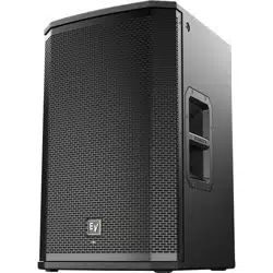
ETX Powered Loudspeakers
ETX-10P, ETX-12P, ETX-15P, ETX-35P, ETX-15SP, and ETX-18SP
en | User Manual


Table of contents
1
Safety 4
2
Description 7
2.1 Quick setup 7
2.2 System features 8
3
System overview 10
3.1 Technical specifications 10
3.2 Dimension drawings 12
3.3 Frequency response graphs 14
4
Operation 17
4.1 Tripod and floor monitor operation 17
4.2 Suspension 21
4.3 Amplifier DSP controls 25
4.4 System status 27
4.5 DSP controls 28
4.5.1 Full-Range loudspeaker DSP control menu 29
4.5.2 Subwoofer DSP control menu 32
4.6 Recommended configurations 36
4.6.1 Daisy-chaining full-range systems 36
4.6.2 Using full-range systems as monitors 37
4.6.3 Stacking full-range systems with subwoofers 38
4.6.4 Subwoofer cardioid array 39
4.7 Removing the subwoofer caster wheels 41
5
Troubleshooting 42
en 3
Electro-Voice User Manual 2014.07 | 04 | F.01U.276.083
Safety
Important Safety instructions:
!
The lightening flash with arrowhead symbol,
within an equilateral triangle is intended to
alert the user to the presence of
uninsulated “dangerous voltage” within the
product’s enclosure that may be sufficient
magnitude to constitute a risk of electric
shock to persons.
WARNING: TO REDUCE THE RISK OF
FIRE OR ELECTRIC SHOCK, DO NOT
OVEREXPOSE THIS APPLIANCE TO RAIN
OR MOISTURE.
AVIS: RISQUE DE CHOC ELECTRIQUE,
NE PAS OUVRIR.
!
The exclamation point within an equilateral
triangle is intended to alert the user to the
presence of important operating and
maintenance (servicing) instructions in the
literature accompanying the appliance.
WARNING: CONNECT ONLY TO MAINS
SOCKET WITH PROTECTIVE EARTHING
CONNECTION.
The asterisk within an equilateral triangle is
intended to inform the user to necessary
installation or removal instructions
regarding equipment or hardware use
relating to the system.
1. Read these instructions.
2. Keep these instructions.
3. Heed all warnings.
4. Follow all instructions.
5. Do not use this apparatus near water.
6. Clean only with a dry cloth.
7. Do not block any ventilation openings. Install in accordance with the manufacturers
instructions.
8. Do not install near any heat sources such as radiators, heat registers, stoves, or other
apparatus (including amplifiers) that produce heat.
9. Do not defeat the safety purpose of the polarized or grounding-type plug. A polarized plug
has two blades with one wider than the other. A grounding type plug has two blades and
a third grounding prong. The wide blade or the third prong is provided for your safety. If
the provided plug does not fit into your outlet, consult an electrician for replacement of
the obsolete outlet.
10. Protect the power cord from being walked on or pinched particularly at plugs,
convenience receptacles, and the point where they exit from the apparatus.
11. Only use attachments/accessories specified by the manufacturer.
12. Unplug the apparatus during lightning storms or when unused for long periods of time.
13. Refer all servicing to qualified service personnel. Servicing is required when the
apparatus has been damaged in any way, such as power-supply cord or plug is damaged,
liquid has been spilled or objects have fallen into the apparatus, the apparatus has been
exposed to rain or moisture, does not operate normally, or has been dropped.
14. To completely disconnect AC power from this apparatus, the power supply cord must be
unplugged.
15. Do not expose this apparatus to dripping or splashing and ensure that no objects filled
with liquids, such as vases, are placed on this apparatus.
16. The AC plug of the power supply cord shall remain readily operable.
1
ETX Powered Loudspeakers
2014.07 | 04 | F.01U.276.083 User Manual Electro-Voice
Management of WEEE (Waste Electrical and Electronic Equipment) (applicable in
Member States of the European Union and other European countries with individual
national polices on the management of WEEE). The symbol on the product or on its
packaging indicates that this product may not be treated as regular household waste,
but has to be disposed through returning it at an Electro-Voice dealer.
FCC information
IMPORTANT: Do not modify this unit! Changes or modifications not expressly approved by the
manufacturer could void the user’s authority, granted by the FCC, to operate the equipment.
Notice!
This equipment has been tested and found to comply with the limits for a Class B digital
device, pursuant to Part 15 of the FCC Rules. These limits are designed to provide reasonable
protection against harmful interference in a residential installation. This equipment generates,
uses and can radiate radio frequency energy and, if not installed and used in accordance with
the instructions, may cause harmful interference to radio communications. However, there is
no guarantee interference will not occur in a particular installation. If this equipment does
cause harmful interference to radio or television reception, which can be determined by
turning the equipment off and on, the user is encouraged to try to correct the interference by
one or more of the following measures:
▪ Reorient or relocate the receiving antenna.
▪ Increase the separation between the equipment and receiver.
▪ Connect the equipment into an outlet on a circuit different from that to which the
receiver is connected.
▪ Consult the dealer or an experienced radio/TV technician.
Precautions
!
If an Electro-Voice loudspeaker is used outdoors on a sunny day, place the
loudspeaker in a shaded or covered area. The loudspeaker amplifiers have
protection circuits that temporarily shut the loudspeaker off when extremely
high temperatures are reached. This can happen on hot days when the
loudspeaker is in direct sunlight.
!
Do not use Electro-Voice loudspeakers in an environment where temperatures
are below 0°C (32°F) or exceed +40°C (104°F).
!
Never expose an Electro-Voice loudspeaker to rain, water, or high moisture.
!
Electro-Voice loudspeakers are easily capable of generating sound pressure
levels sufficient to cause permanent hearing damage to anyone within normal
coverage distance. Caution should be taken to avoid prolonged exposure to
sound pressure levels exceeding 90 dB.
en 5
Electro-Voice User Manual 2014.07 | 04 | F.01U.276.083

Suspension
!
Warning!
Suspending any object is potentially dangerous and should only be attempted by individuals
who have a thorough knowledge of the techniques and regulations of suspending objects
overhead. Electro-Voice strongly recommends all loudspeakers be suspended taking into
account all current national, federal, state, and local regulations. It is the responsibility of the
installer to ensure all loudspeakers are safely installed in accordance with all such
regulations. When loudspeakers are suspended, Electro-Voice strongly recommends the
system be inspected at least once a year. If any sign of weakness or damage is detected,
remedial action should be taken immediately. The user is responsible for making sure the wall
or ceiling is capable of supporting the loudspeaker. Any hardware used to suspend a
loudspeaker not associated with Electro-Voice is the responsibility of others.
ETX Powered Loudspeakers
2014.07 | 04 | F.01U.276.083 User Manual Electro-Voice
Description
Thank you for choosing an Electro-Voice powered loudspeaker system. Please take time to
consult the manual to understand all the features built into your EV system and fully utilize its
performance capabilities.
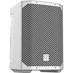
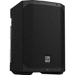
The ETX Powered Loudspeakers are a high-end wood loudspeaker family; consisting of the
ETX-10P, ETX-12P, ETX-15P, ETX-35P, ETX-15SP, and ETX-18SP. Features professional fit and
finish, durable, high power systems offers easy portability. The integrated LCD screen allows
access to multiple DSP (Digital Signal Processing) settings and system status. ETX Powered
Loudspeakers offer the best-in class sound through design, innovation, amplification, and DSP
inspired by EV’s legendary engineering team.
Quick setup
The ETX Powered Loudspeakers from Electro-Voice are fully integrated audio systems with
carefully matched electronics and transducers. These products make it easy to set up a high
quality system quickly with a minimum amount of cables and external electronics.
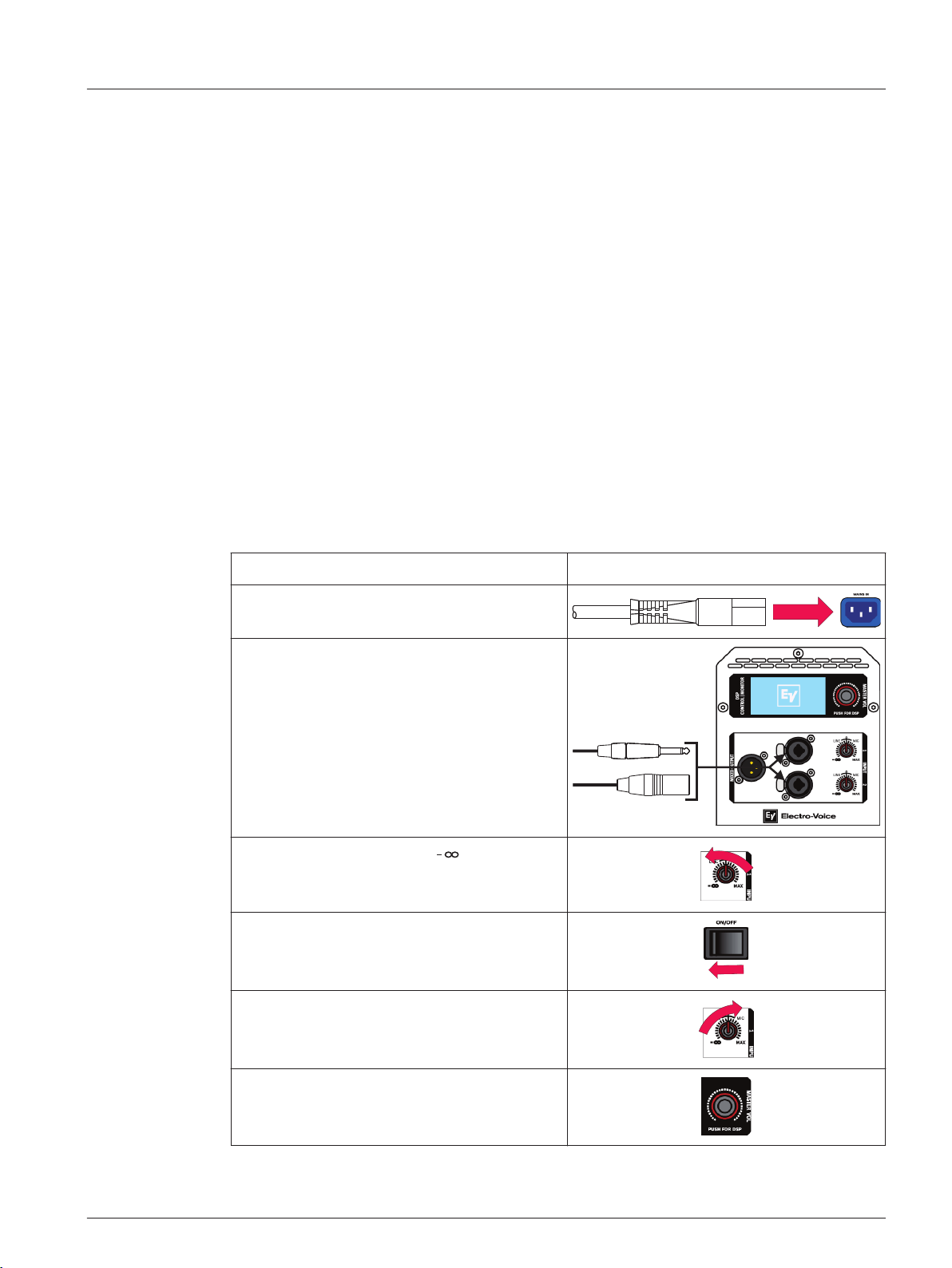
Full-Range loudspeaker
Models: ETX-10P, ETX-12P, ETX-15P, and ETX-35P
To set up a full-range loudspeaker, do the following:
Step Illustration
1. Connect the AC power cord from a
grounded line receptacle to the MAINS IN.
2. Connect the XLR or TRS cable from an
audio source to INPUT 1 or INPUT 2.
3. Adjust the input gain to (infinity).
4. Switch POWER to ON.
5. From the DSP home screen, increase the
input gain to the desired sound output.
6. Adjust the MASTER VOL knob to the
desired volume.
2
2.1
en 7
Electro-Voice User Manual 2014.07 | 04 | F.01U.276.083
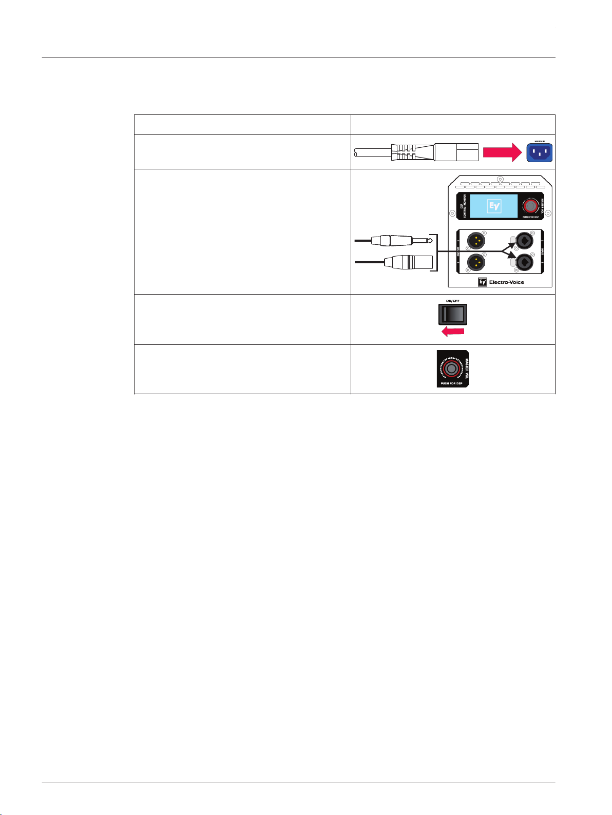
Subwoofer
Models: ETX-15SP and ETX-18SP
To set up a subwoofer, do the following:
Step Illustration
1. Connect the AC power cord from a
grounded line receptacle to the MAINS IN.
2. Connect the XLR or TRS cable from an
audio source to INPUT 1 or INPUT 2.
3. Switch POWER to ON.
4. Adjust the MASTER VOL knob to the
desired volume.
System features
ETX Powered Loudspeakers from Electro-Voice build upon the legacy and heritage of EV, to
deliver the most advanced powered loudspeaker products for portable and permanent
applications. The output, response and coverage pattern of EV transducers are all optimized
via the breakthrough design approach known as SST (Signal Synchronized Transducers),
combined with state-of-the-art on-board DSP which is accessed via an easy-to-use single-knob
interface. EV designed and manufactured transducers include SMX woofer technology using
composite cone materials, flux stabilizing rings, and thermal management. This transducer
yields lower distortion, smooth response and high SPL. The high-efficiency DH3-B
compression driver has a convex diaphragm driving a coherent phase device extending
frequency response to 20 kHz. The ETX Powered Loudspeaker family features three (3) two-
way loudspeakers (10-inch, 12-inch and 15-inch with a 1.5-inch titanium compression driver),
a single three-way loudspeaker, and subwoofers with 15-inch and 18-inch drivers. ETX
Powered Loudspeakers combine EV-engineered intelligent DSP, high-powered amplifiers and
high-efficiency transducers to deliver that legendary EV sound and performance.
ETX-10P—10-inch two-way powered loudspeaker system
▪ 2000 W amplifier and 134 dB peak SPL
▪ Single-knob DSP includes presets for multiple configurations and top+sub combinations
(performance style, locations, and space)
▪ Loudspeaker system performance monitoring via integrated LCD and front panel LED
▪ SST design assures precise and consistent coverage
▪ Designed for floor, stacked, or tilt pole mount (0 or 7.5 degrees) for portable or
permanent installation (Eight (8) M10 threaded suspension points)
2.2
ETX Powered Loudspeakers
2014.07 | 04 | F.01U.276.083 User Manual Electro-Voice

ETX-12P—12-inch two-way powered loudspeaker system
▪ 2000 W amplifier and 135 dB peak SPL
▪ Single-knob DSP includes presets for multiple configurations and top+sub combinations
(performance style, locations, and space)
▪ Loudspeaker system performance monitoring via integrated LCD and front panel LED
▪ SST design assures precise and consistent coverage
▪ Designed for floor, stacked, or tilt pole mount (0 or 7.5 degrees) for portable or
permanent installation (Eight (8) M10 threaded suspension points)
ETX-15P—15-inch two-way powered loudspeaker system
▪ 2000 W amplifier and 135 dB peak SPL
▪ Single-knob DSP includes presets for multiple configurations and top+sub combinations
(performance style, locations, and space)
▪ Loudspeaker system performance monitoring via integrated LCD and front panel LED
▪ SST design assures precise and consistent coverage
▪ Designed for floor, stacked, or tilt pole mount (0 or 7.5 degrees) for portable or
permanent installation (Eight (8) M10 threaded suspension points)
ETX-35P—15-inch three-way powered loudspeaker system
▪ 2000 W amplifier and 136 dB peak SPL
▪ Single-knob DSP includes presets for multiple configurations and top+sub combinations
(performance style, locations, and space)
▪ Loudspeaker system performance monitoring via integrated LCD and front panel LED
▪ Features three high-sensitivity transducers, for high output sound which is optimized for
precise coverage and low distortion
▪ Designed for floor, stacked, or a combo pole cup (insert and threaded) for portable or
permanent installation (Eight (8) M10 threaded suspension points)
ETX-15SP—15-inch powered subwoofer loudspeaker system
▪ 1800 W amplifier and 134 dB peak SPL
▪ Single-knob DSP includes presets for multiple configurations and top+sub combinations
(performance style, locations, and space)
▪ Loudspeaker system performance monitoring via integrated LCD and front panel LED
▪ Includes DSP preset for true cardioid performance
▪ Enclosure includes removable casters and a combo pole cup (insert and threaded) for
use with the two-way models
ETX-18SP—18-inch powered subwoofer loudspeaker system
▪ 1800 W amplifier and 135 dB peak
▪ Single-knob DSP includes presets for multiple configurations and top+sub combinations
(performance style, locations, and space)
▪ Loudspeaker system performance monitoring via integrated LCD and front panel LED
▪ Includes DSP preset for true cardioid performance
▪ Enclosure includes removable casters and a combo pole cup (insert and threaded) for
use with the two-way models
en 9
Electro-Voice User Manual 2014.07 | 04 | F.01U.276.083

System overview
Technical specifications
ETX-10P, ETX-12P, and ETX-15P
ETX-10P ETX-12P ETX-15P
Frequency Response (-3 dB): 85 Hz – 20 kHz
1
55 Hz – 20 kHz
1
48 Hz – 20 kHz
1
Frequency Range (-10 dB): 65 Hz – 20 kHz
1
43 Hz – 20 kHz
1
40 Hz – 20 kHz
1
Maximum SPL: 134 dB peak
2
135 dB peak
2
135 dB peak
2
Coverage (H x V): 90° x 60°
Power Rating: 2000 W
LF Transducer: SMX2100 254 mm
(10 in)
SMX2120 300
mm (12 in)
SMX2150 380 mm
(15 in)
HF Transducer: DH3-B 1.25-in titanium compression driver
Crossover Frequency: 1700 Hz 1600 Hz 1500 Hz
Connectors: (2) XLR/TRS combo jack and (1) XLR link output
Enclosure: 18 mm, 13-ply birch plywood with EVCoat
Grille: 16AWG steel with powdercoat
Suspension: (8) M10 suspension points
Dimensions (H x W x D): 526 mm x 330 mm
x 365 mm (21 in x
13 in x 14 in)
613 mm x 381
mm x 400 mm
(24 in x 15 in x
16 in)
691 mm x 431 mm
x 447 mm (27 in x
17 in x 18 in)
Net Weight: 20.3 kg (44.8 lb) 23.6 kg (52.0 lb) 27.7 kg (61.1 lb)
Shipping Weight: 22.9 kg (50.5 lb) 26.8 kg (59.1 lb) 31.5 kg (69.5 lb)
Power Consumption: 100 – 240 V~, 50 – 60 Hz, 1.6 – 0.8 A
3
1. Full space measurement using the music DSP preset.
2. Maximum SPL is measured at 1 m using broadband pink noise at maximum output.
3. Current rating is 1/8 power.
3
3.1
ETX Powered Loudspeakers
2014.07 | 04 | F.01U.276.083 User Manual Electro-Voice

ETX-35P
ETX-35P
Frequency Response (-3 dB): 48 Hz – 20 kHz
1
Frequency Range (-10 dB): 38 Hz – 20 kHz
1
Maximum SPL: 136 dB peak
2
Coverage (H x V): 60° x 40°
Power Rating: 2000 W
LF Transducer: SMX2151 380 mm (15 in)
MB Transducer: EVS-6C 6.5-in mid-bass driver
HF Transducer: DH3-B 1.25-in titanium compression driver
Crossover Frequency: 700 Hz, 2900 Hz
Connectors: (2) XLR/TRS combo jack and (1) XLR link output
Enclosure: 18 mm, 13-ply birch plywood with EVCoat
Grille: 16AWG steel with powdercoat
Suspension: (8) M10 suspension points
Dimensions (H x W x D): 1023 mm x 469 mm x 426 mm (40 in x 18 in x 17 in)
Net Weight: 38.2 kg (84.2 lb)
Shipping Weight: 42.8 kg (94.4 lb)
Power Consumption: 100 – 240 V~, 50 – 60 Hz, 1.6 – 0.8 A
3
1. Full space measurement using the music DSP preset.
2. Maximum SPL is measured at 1 m using broadband pink noise at maximum output.
3. Current rating is 1/8 power.
en 11
Electro-Voice User Manual 2014.07 | 04 | F.01U.276.083
ETX-15SP and ETX-18SP
ETX-15SP ETX-18SP
Frequency Response (-3 dB): 37 Hz – 150 Hz
1
33 Hz – 150 Hz
1
Frequency Range (-10 dB): 32 Hz – 180 Hz
1
28 Hz – 180 Hz
1
Maximum SPL: 134 dB peak
2
135 dB peak
2
Power Rating: 1800 W
LF Transducer: DVX3159A 380 mm (15 in) DVX3180A 457 mm (18 in)
Low Pass Frequency: Adjustable: 80 Hz, 100 Hz, 120 Hz, 150 Hz
Connectors: (2) XLR/TRS Combo Jack and (2) XLR link Output
Enclosure: 18 mm, 13-ply birch plywood with EVCoat
Grille: 16AWG steel with powdercoat
Dimensions (H x W x D): 471 mm x 576 mm x 825 mm
(19 in x 23 in x 32 in)
550 mm x 675 mm x 910 mm
(22 in x 27 in x 36 in)
Dimensions (H x W x D):
without casters
471 mm x 576 mm x 692 mm
(19 in x 23 in x 27 in)
550 mm x 675 mm x 777 mm
(22 in x 27 in x 31 in)
Net Weight: 41.7 kg (91.9 lb) 51.8 kg (114.2 lb)
Shipping Weight: 46.8 kg (103.2 lb) 58.9 kg (129.9 lb)
Power Consumption: 100 – 240 V~, 50 – 60 Hz, 1.6 – 0.8 A
3
1. Half space measurement using the music DSP preset and 150 Hz low pass.
2. Maximum SPL is measured at 1 m using broadband pink noise at maximum amplifier
output.
3. Current rating is 1/8 power.
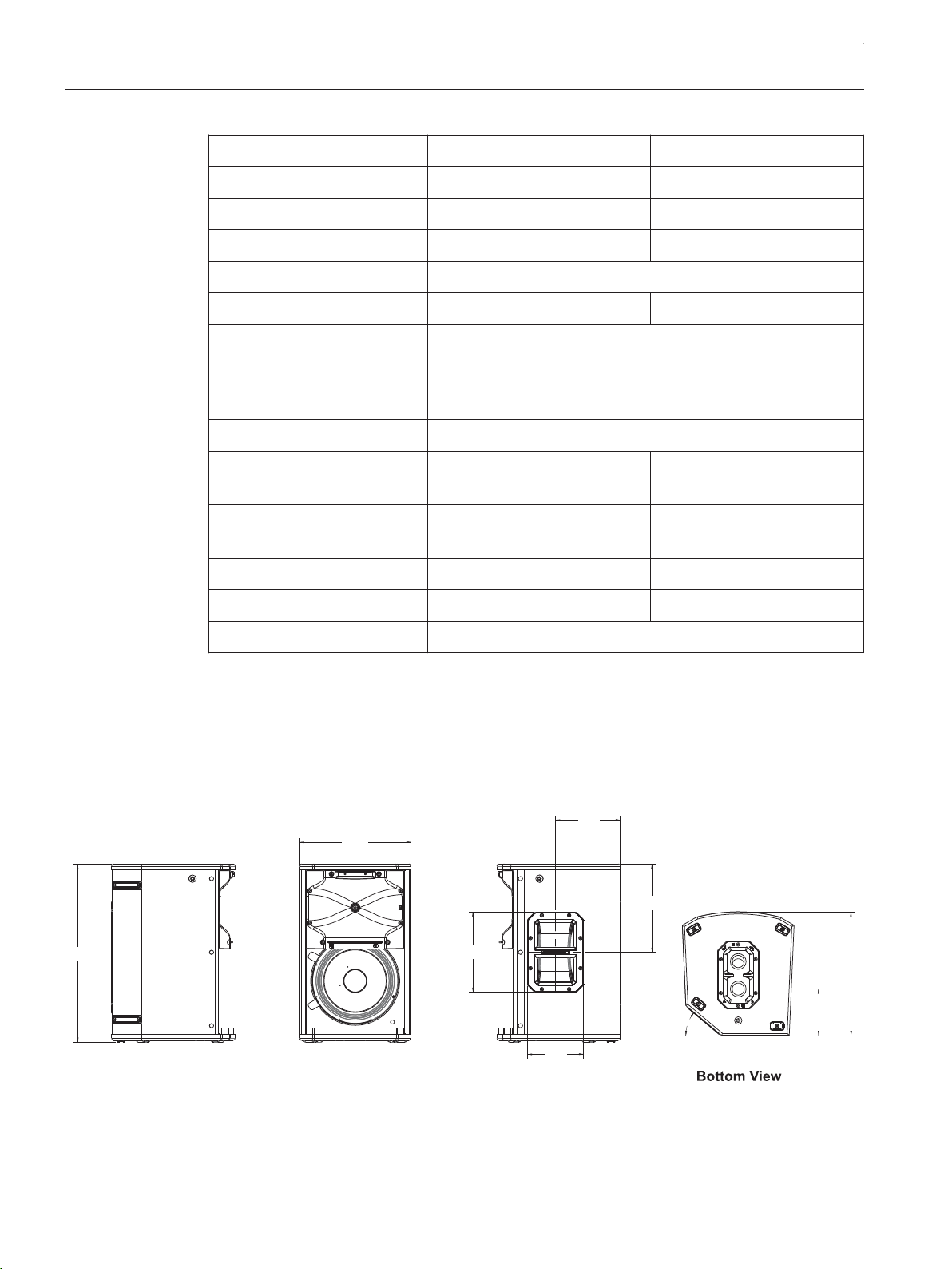
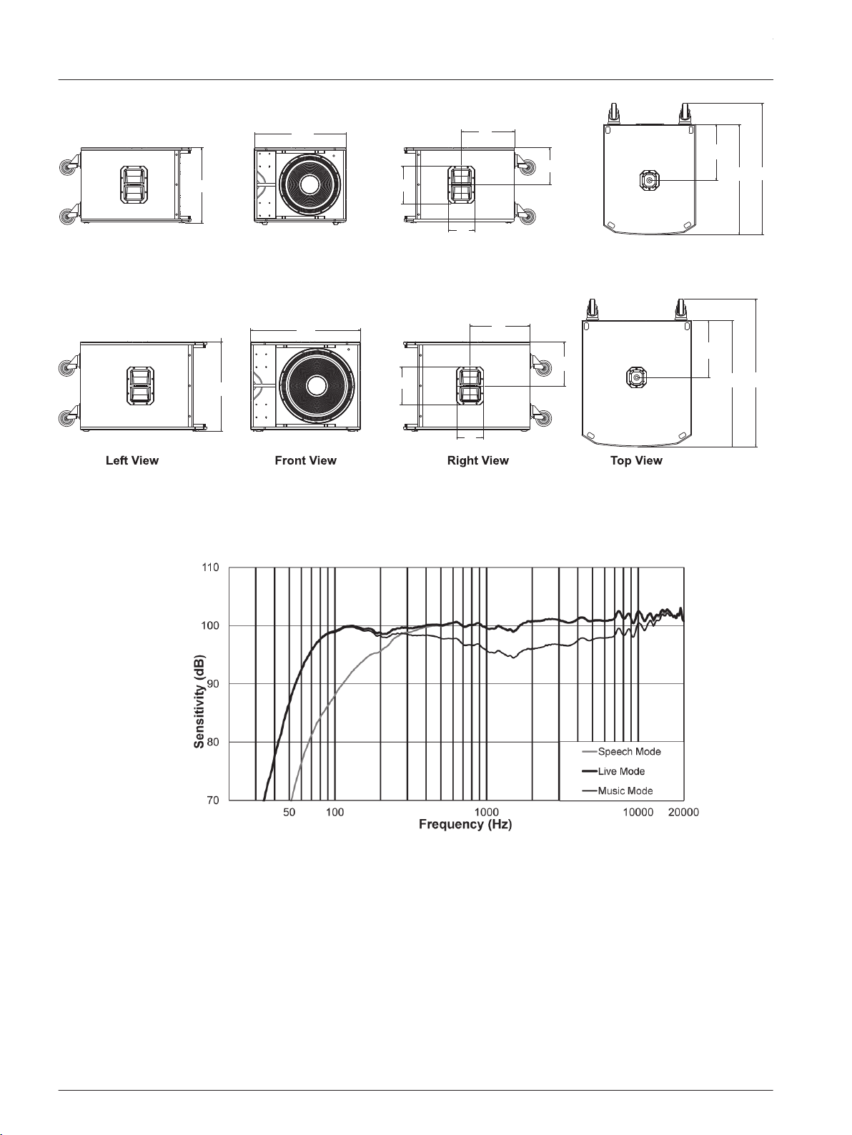
Dimension drawings
330 mm
[13 in]
40°
526 mm
[21 in]
236 mm
[9 in]
191 mm
[8 in]
166 mm
[7 in]
261 mm
[10 in]
365 mm
[14 in]
137 mm
[5 in]
Left View
Front View
Right View
Figure 3.1: ETX-10P dimension drawing
3.2
ETX Powered Loudspeakers
2014.07 | 04 | F.01U.276.083 User Manual Electro-Voice
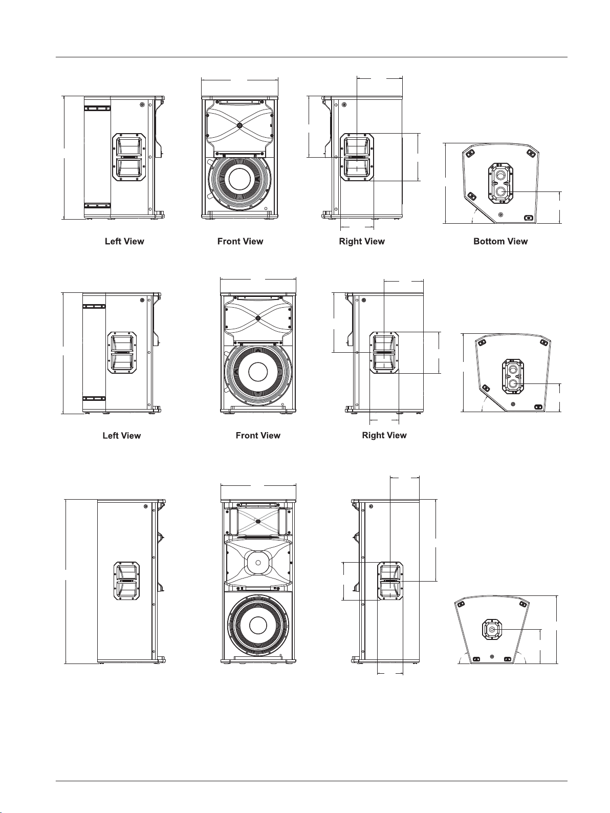
40°
613 mm
[24 in]
381 mm
[15 in]
304 mm
[12 in]
225 mm
[9 in]
166 mm
[7 in]
400 mm
[16 in]
236 mm
[9 in]
159 mm
[6 in]
Figure 3.2: ETX-12P dimension drawing
40°
431 mm
[17 in]
691 mm
[27 in]
224 mm
[9 in]
342 mm
[13 in]
236 mm
[9 in ]
447 mm
[18 in]
161 mm
[6 in]
Bottom View
166 mm
[7 in ]
Figure 3.3: ETX-15P dimension drawing
75° 75°
Bottom View
Right ViewFront View
Left View
469 mm
[18 in]
1023mm
[40 in]
236 mm
[9 in]
182 mm
[7 in]
166 mm
[7 in]
508 mm
[20 in]
213 mm
[8 in]
426 mm
[17 in]
Figure 3.4: ETX-35P dimension drawing
en 13
Electro-Voice User Manual 2014.07 | 04 | F.01U.276.083
471 mm
[19 in]
576 mm
[23 in]
236 mm
[9 in]
333 mm
[13 in]
166 mm
[7 in]
232 mm
[9 in ]
351 mm
[14 in]
692 mm
[27 in]
825 mm
[32 in]
Left View
Right ViewFront View
Top View
Figure 3.5: ETX-15SP dimension drawing
550 mm
[22 in]
675 mm
[27 in]
236 mm
[9 in]
166 mm
[7 in]
368 mm
[14 in]
271mm
[11 in]
351 mm
[14 in]
777 mm
[31 in]
910 mm
[36 in]
Figure 3.6: ETX-18SP dimension drawing
Frequency response graphs
Figure 3.7: ETX-10P frequency response graph: speech, live, and music modes
3.3
ETX Powered Loudspeakers
2014.07 | 04 | F.01U.276.083 User Manual Electro-Voice
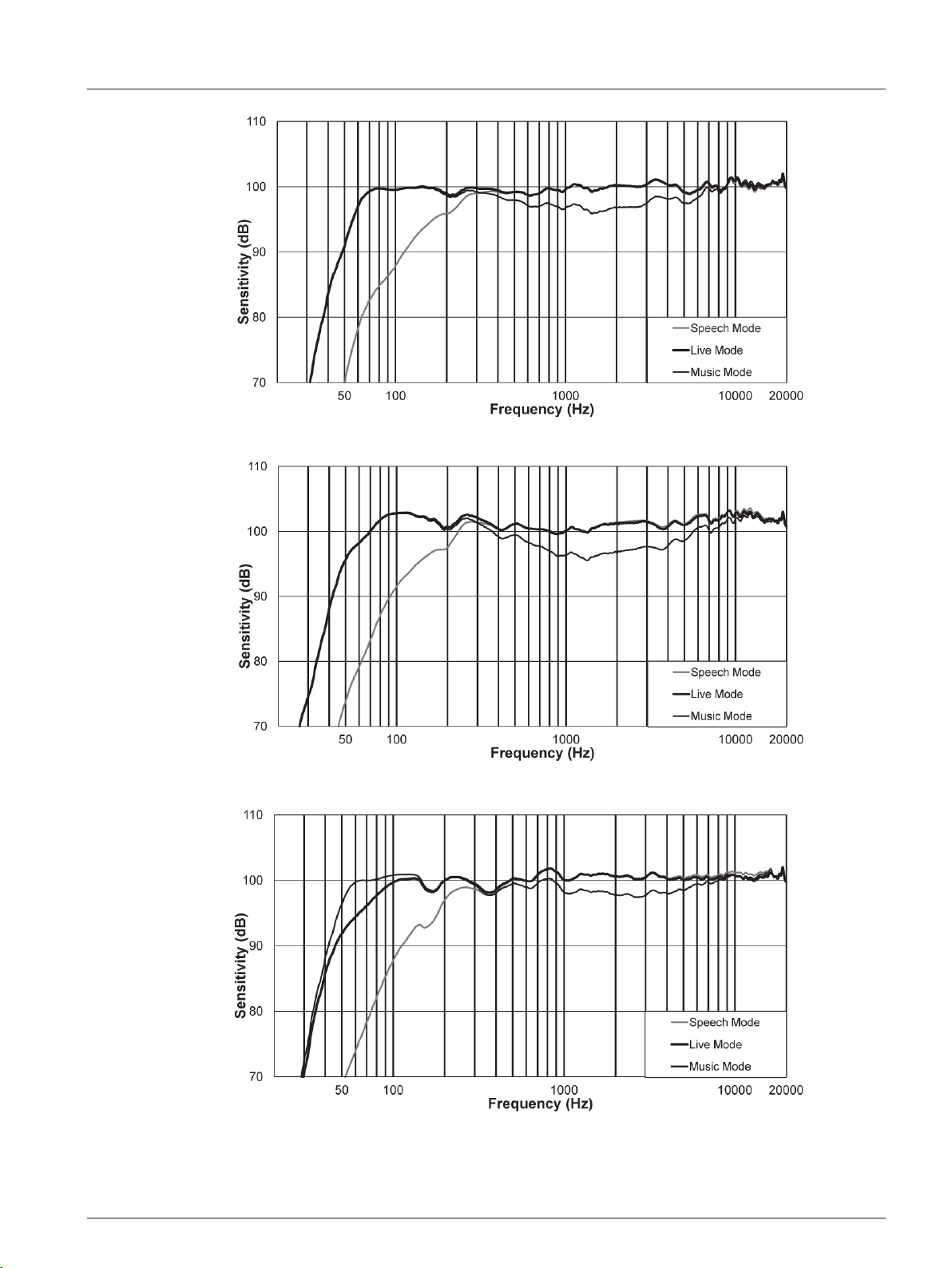
Figure 3.8: ETX-12P frequency response graph: speech, live, and music modes
Figure 3.9: ETX-15P frequency response graph: speech, live, and music modes
Figure 3.10: ETX-35P frequency response graph: speech, live, and music modes
en 15
Electro-Voice User Manual 2014.07 | 04 | F.01U.276.083
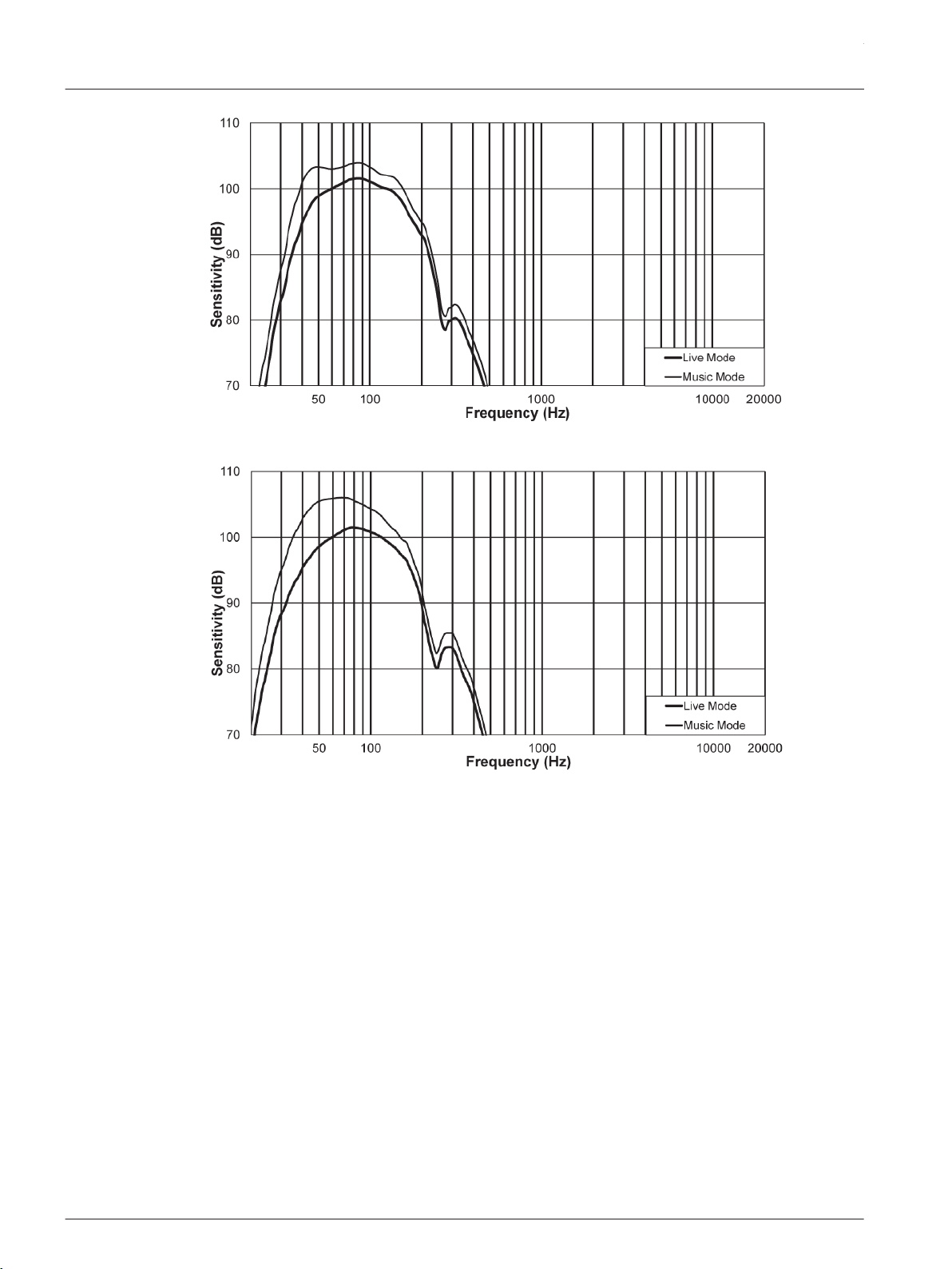
Figure 3.11: ETX-15SP frequency response graph: live and music modes
Figure 3.12: ETX-18SP frequency response graph: live and music modes
ETX Powered Loudspeakers
2014.07 | 04 | F.01U.276.083 User Manual Electro-Voice
Operation
Tripod and floor monitor operation
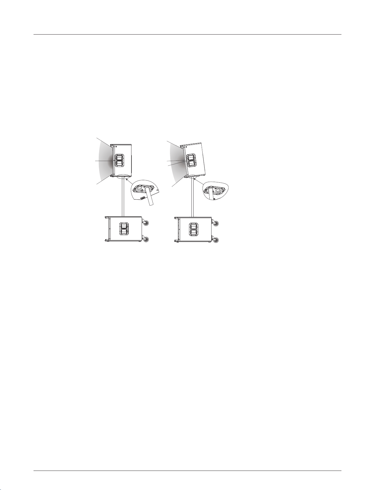
Multi-angle pole cup
The multi-angle pole cup is used to position the ETX-10P, ETX-12P and ETX-15P loudspeakers
for optimal sound coverage. The multi-angle pole cup has two (2) positions 0° and 7.5°. The 0°
position points the sound horizontally straight towards the audience. The 7.5° position points
the sound at an angle towards the audience and is used when the loudspeaker is above the
audience.
0°
7.5°
Figure 4.1: Optimal coverage multi-angle pole cup 0° (left) and multi-angle pole cup 7.5° (right)
Combo pole cup
ETX-35P, ETX-15SP, and ETX-18SP subwoofers use a M20 threaded and 35 mm (1 3/8 in)
combination cup to be compatible with both types of poles. M20 threaded poles provide a
more secure connection to the subwoofer than the standard 35 mm (1 3/8 in) pole. If using an
M20 threaded pole with the ETX-35P, always place the threads into the subwoofer.
4
4.1
en 17
Electro-Voice User Manual 2014.07 | 04 | F.01U.276.083
Tripod or pole mount
ETX-10P, ETX-12P, and ETX-15P loudspeakers mount on a tripod stand or on a pole above a
subwoofer.
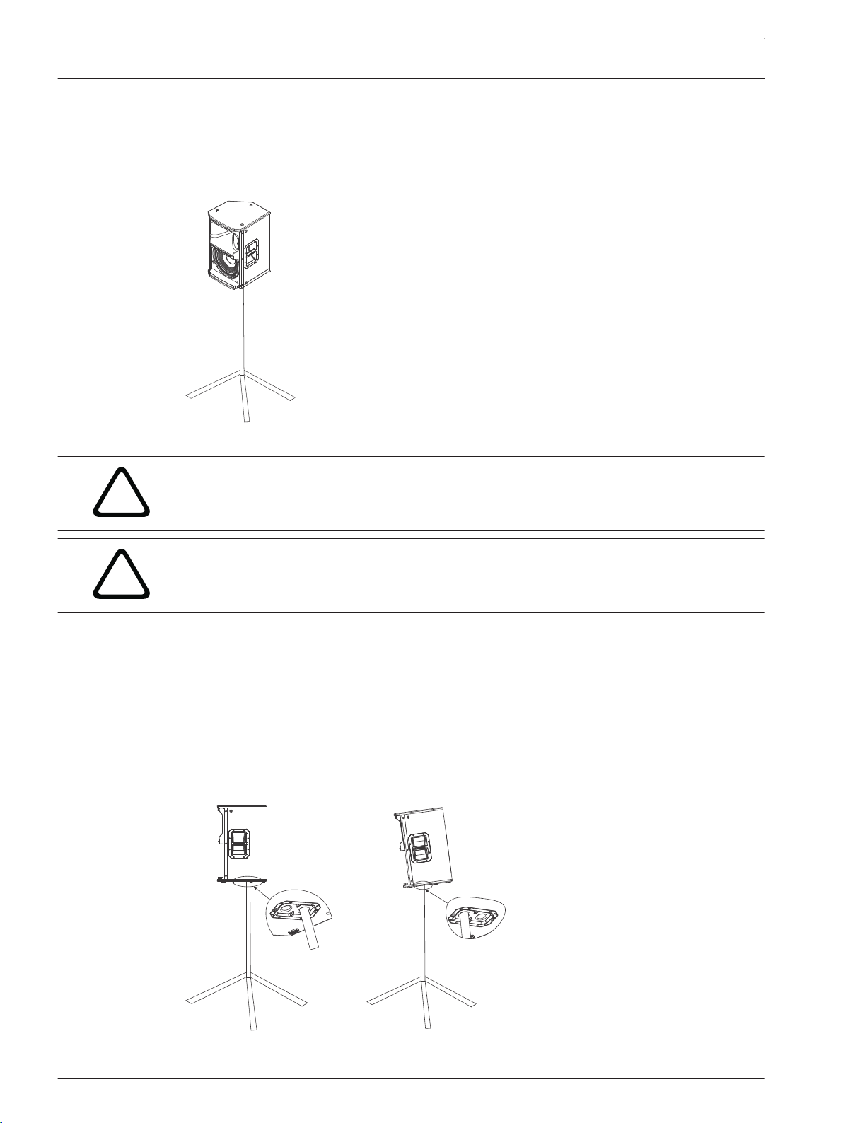
Mounting a loudspeaker on a tripod stand
Figure 4.2: Full-Range models on tripod stand
!
Caution!
Tripod is not evaluated for safety with this loudspeaker. Check the specifications of the tripod
stand to be certain it is capable of supporting the weight of the loudspeaker.
!
Caution!
Two (2) person lift and placement is recommended for the heavier loudspeakers. Single
person lift and placement of heavier loudspeakers could cause injury.
To mount a loudspeaker on a tripod stand, do the following:
1. Place the tripod stand on a level stable surface.
▪ Fully extend the legs on the tripod stand.
▪ Do not compromise the tripod stands structural integrity by trying to make the stand
taller.
▪ Do not attempt to suspend more than one (1) loudspeaker on a stand designed for a
single loudspeaker.
2. Using two (2) hands lift the loudspeaker.
3. Set the multi-angle pole cup located on the bottom of the loudspeaker onto the pole.
Figure 4.3: Multi-angle pole cup 0° (left) and multi-angle pole cup 7.5° (right)
ETX Powered Loudspeakers
2014.07 | 04 | F.01U.276.083 User Manual Electro-Voice
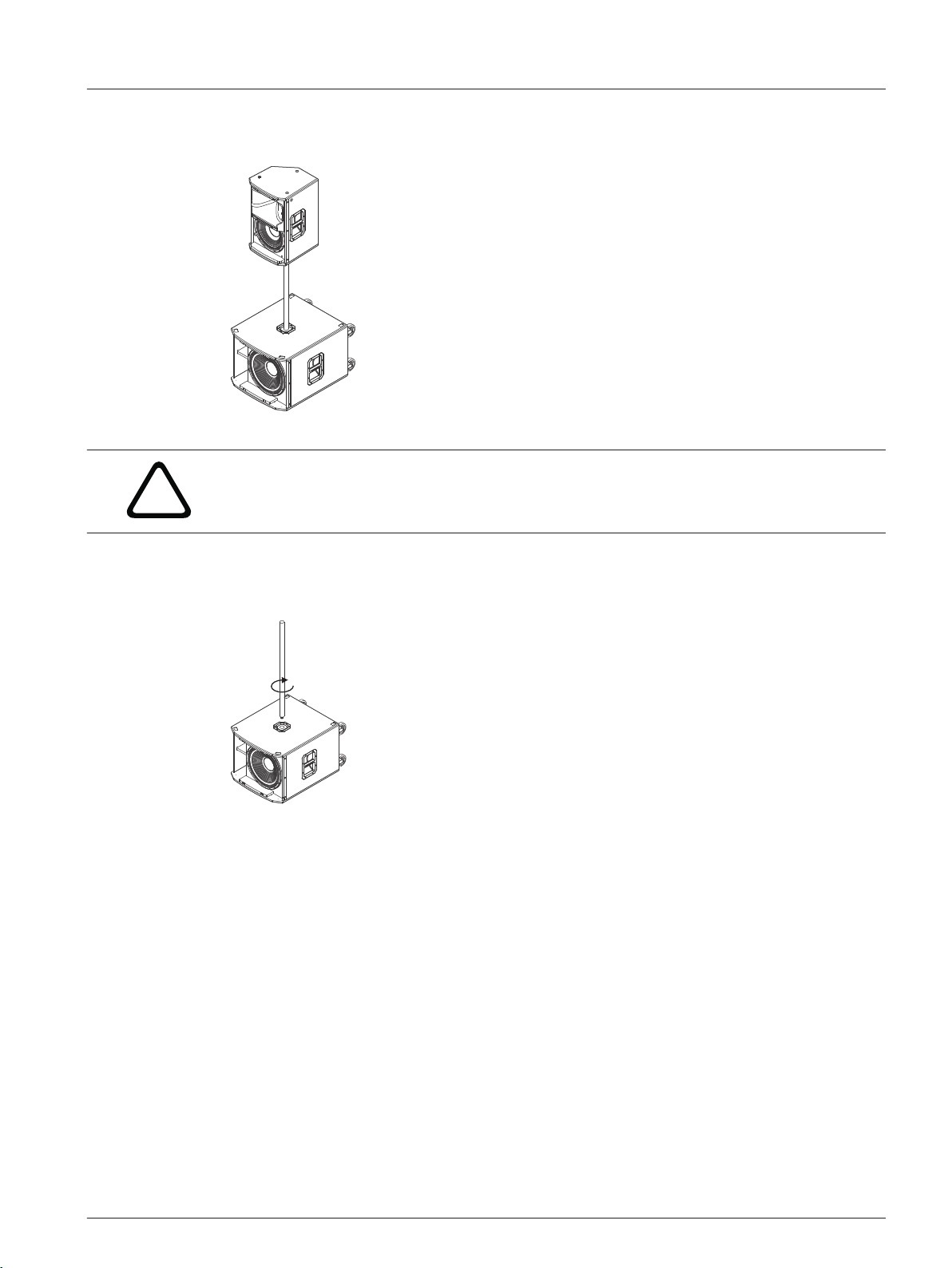
Mounting a loudspeaker on a pole
Figure 4.4: Full-Range/sub stack with pole mount
!
Caution!
Two (2) person lift and placement is recommended for the heavier loudspeakers. Single
person lift and placement of heavier loudspeakers could cause injury.
To mount a loudspeaker above a subwoofer on a pole, do the following:
1. Place the subwoofer on a level stable surface.
2. Insert the M20 threaded pole into the combo pole cup on the top of the subwoofer.
Turn the pole
clockwise
3. Turn the M20 threaded pole clockwise to secure the pole to the subwoofer.
4. Using two (2) hands lift the loudspeaker.
5. Set the multi-angle pole cup located on the bottom of the loudspeaker onto the pole.
en 19
Electro-Voice User Manual 2014.07 | 04 | F.01U.276.083
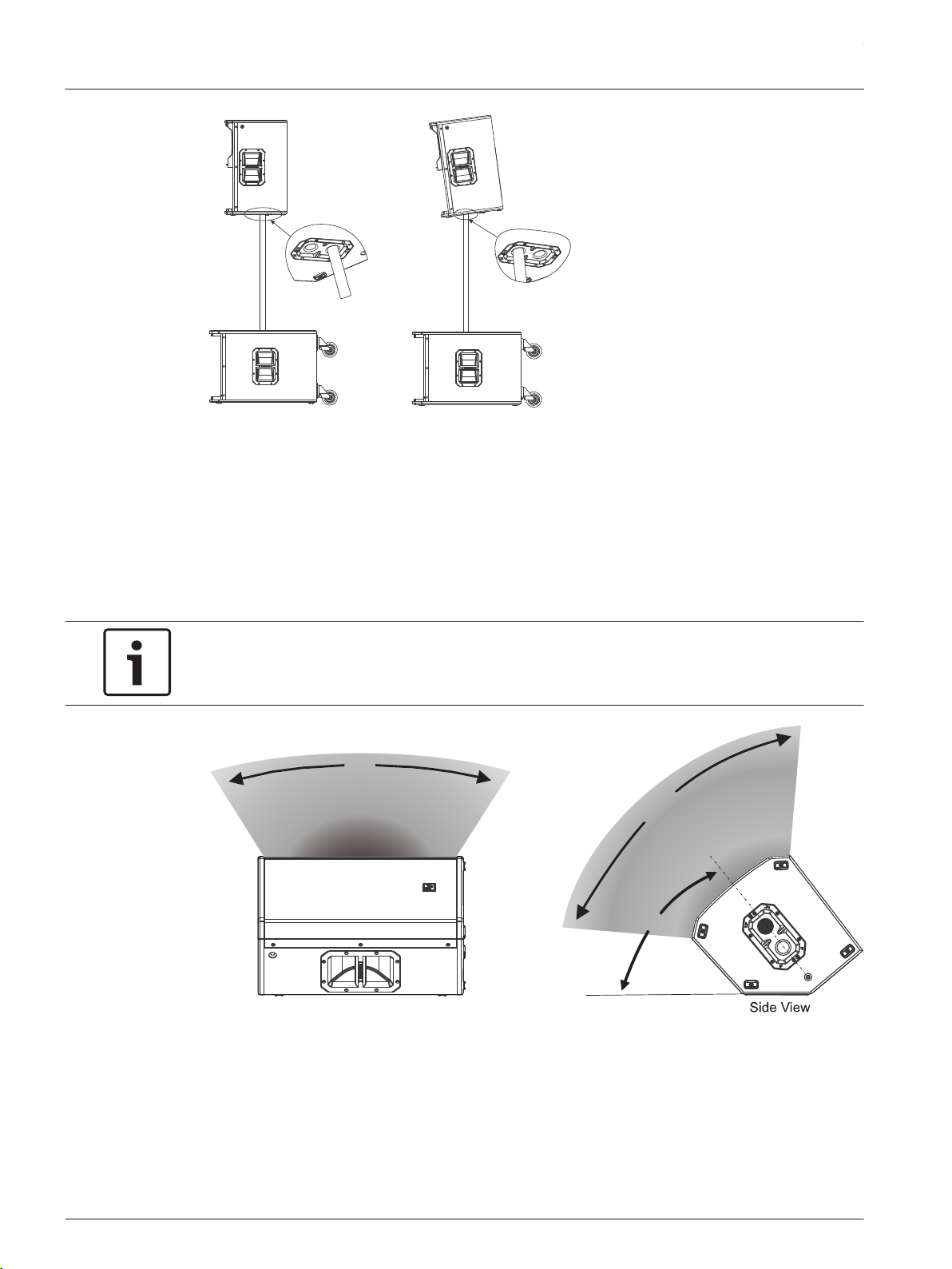
Figure 4.5: Multi-angle pole cup 0° (left) and multi-angle pole cup 7.5° (right)
Floor monitor
ETX-10P, ETX-12P, and ETX-15P loudspeakers may be used as a floor monitor by placing the
speaker on the integral monitor angle.
To set up a loudspeaker as a floor monitor, do the following:
1. Place the loudspeaker on a level stable surface.
2. Safely route cables to prevent injury to performers, production crew, and audience
members.
Notice!
Secure cables with wire ties or tape whenever possible.
Front View
60º
OPTIMAL
COVERAGE
90º
OPTIMAL
COVERAGE
40º
MONITOR
ANGLE
Figure 4.6: Optimum coverage in monitor position
ETX Powered Loudspeakers
2014.07 | 04 | F.01U.276.083 User Manual Electro-Voice
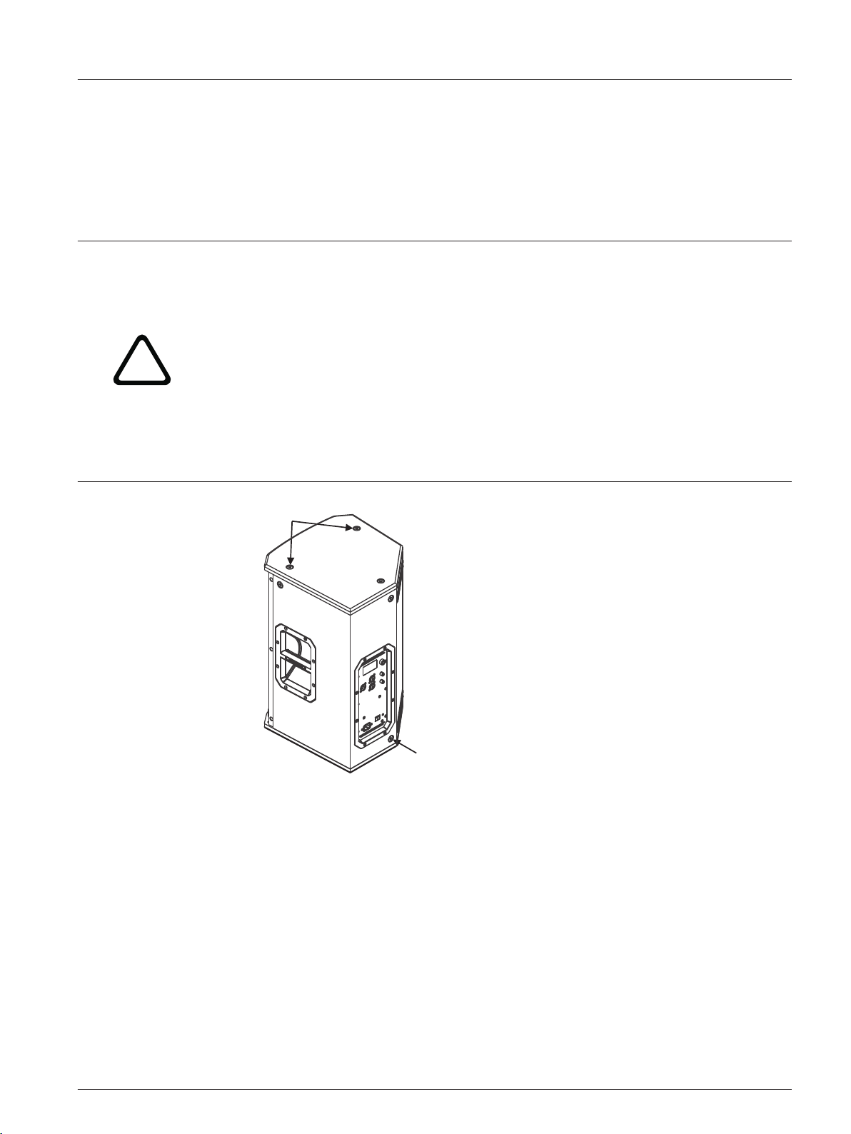
Suspension
The ETX-10P, ETX-12P, ETX-15P, and ETX-35P enclosures have eight (8) M10 threaded points;
six (6) points on top of the enclosure and two (2) points on the bottom. Forged shoulder
eyebolts rated for overhead suspension may be used to suspend an individual loudspeaker,
such as the EBK-M10 accessory.
!
Warning!
Suspending any object is potentially dangerous and should only be attempted by individuals
who have a thorough knowledge of the techniques and regulations of suspending objects
overhead. Electro-Voice strongly recommends all loudspeakers be suspended taking into
account all current national, federal, state, and local regulations. It is the responsibility of the
installer to ensure all loudspeakers are safely installed in accordance with all such
regulations. When loudspeakers are suspended, Electro-Voice strongly recommends the
system be inspected at least once a year. If any sign of weakness or damage is detected,
remedial action should be taken immediately. The user is responsible for making sure the wall
or ceiling is capable of supporting the loudspeaker. Any hardware used to suspend a
loudspeaker not associated with Electro-Voice is the responsibility of others.
Top Suspension
Points
Bottom Suspension
Point
Figure 4.7: Suspension points
Prior to use, inspect the suspension points and associated hardware for any cracks,
deformations, broken welds, corrosion, missing or damaged components which could reduce
the suspension points strength. Replace any damaged hardware. Never exceed the limitations
or maximum recommended load intended for the suspension points. As an added safety
measure, it is suggested the user install an extra suspension point back to the building
structural supports. This redundant safety point should have as little slack as possible (less
than one (1) inch is preferable). Prior to each use, inspect the loudspeaker enclosures for any
cracks, deformations, missing or damaged components, which could reduce enclosure
strength. Replace any loudspeaker systems damaged or missing hardware.
4.2
en 21
Electro-Voice User Manual 2014.07 | 04 | F.01U.276.083
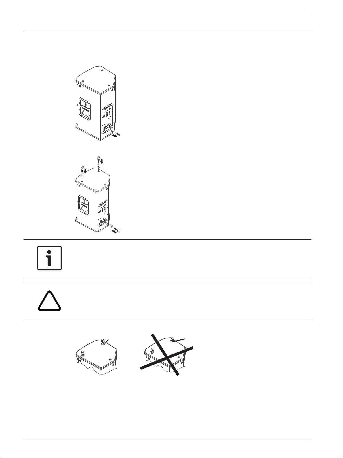
Installing the eyebolts
To install the eyebolts, do the following:
1. Remove the M10 screws from the suspension points.
2. Replace the M10 screw with the fender washer and eyebolt.
Notice!
If the eyebolts are removed reinstall the screws.
If the screws are not reinstalled air leaks occur in the enclosure, resulting in undesirable
performance.
!
Warning!
Eyebolts must be fully seated and oriented in the plane of pull. Always use fender washers at
least 1.5 inch in diameter and 1/16 inch thick under the eyebolt to distribute the load on the
enclosure.
No
Washer
Used
Washer
Used
Figure 4.8: Eyebolt shown with and without washer
ETX Powered Loudspeakers
2014.07 | 04 | F.01U.276.083 User Manual Electro-Voice
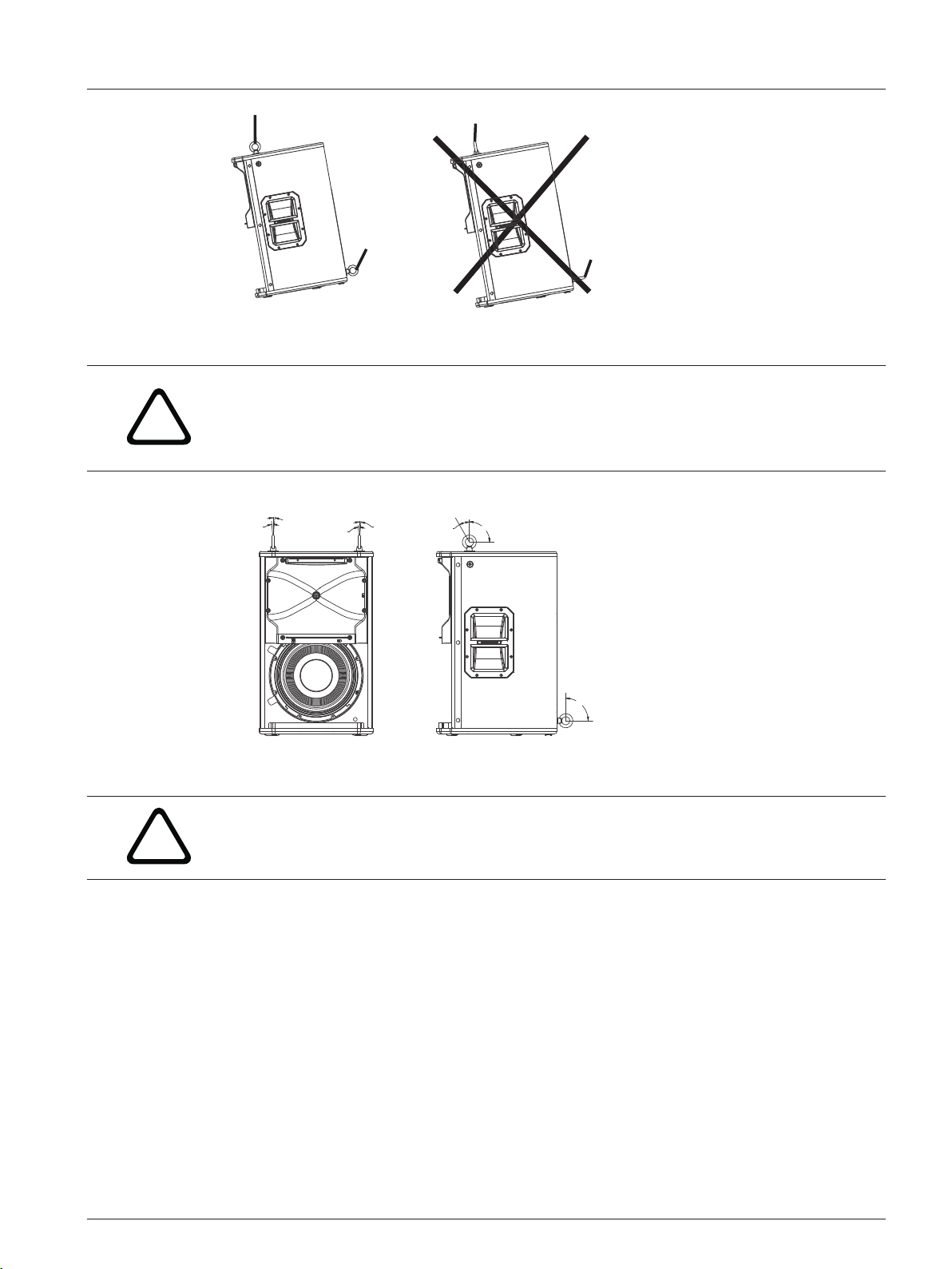
Correct Incorrect
Figure 4.9: Eyebolts shown oriented in the plane of pull
!
Warning!
Never exceed the limitations or maximum recommended working load for Electro-Voice
loudspeakers.
Disregarding this warning could result in serious injury or death.
5° MAX
5° MAX
5° MAX
5° MAX
30°
90°
90°
50 lb per Suspension Point
Figure 4.10: Maximum working load - vertical orientation
!
Warning!
Never suspend ETX Powered Loudspeakers in a vertical column array.
Disregarding this warning could result in serious injury or death.
en 23
Electro-Voice User Manual 2014.07 | 04 | F.01U.276.083
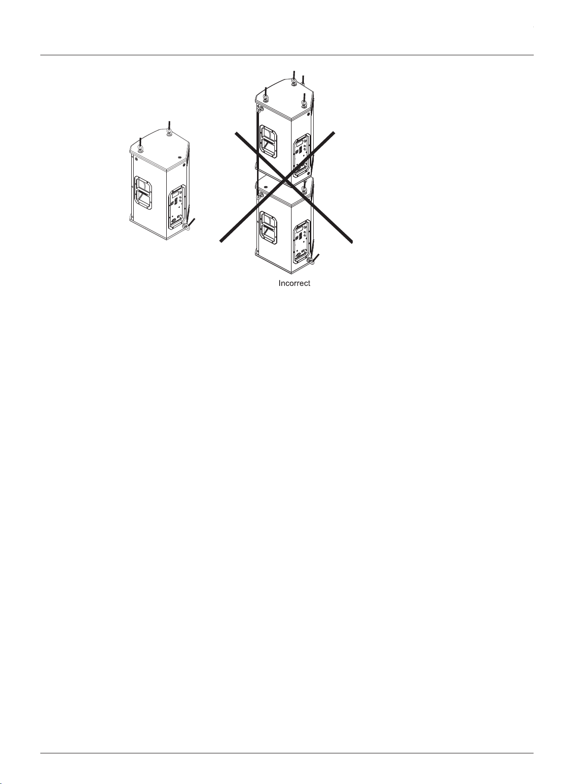
Correct
Figure 4.11: Loudspeaker vertical suspension
ETX Powered Loudspeakers
2014.07 | 04 | F.01U.276.083 User Manual Electro-Voice
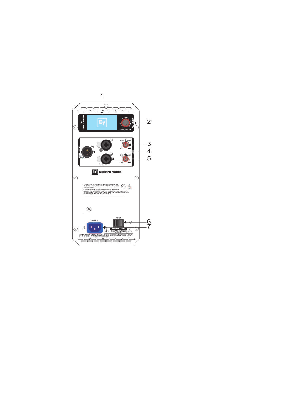
Amplifier DSP controls
The amplifier has a combination of controls and connectors to ensure the most versatile
loudspeaker system.
Full-Range loudspeaker control and monitoring interface
The full-range loudspeaker DSP control menu selections are available for the ETX-10P,
ETX-12P, ETX-15P, and ETX-35P.
Figure 4.12: Full-Range loudspeaker amplifier panel
1. LCD – DSP control and monitoring interface.
2. MASTER VOL – Adjusts the sound level.
DSP – Scroll through the menu and select the available choices. Push the MASTER VOL
knob to enter the DSP menu. For more information, see DSP controls, page 28.
3. INPUT LEVEL – Level control for adjusting the individual inputs’ level. The 12 o’clock
position is unity gain (no gain or attenuation), the range to the left of zero (0). LINE and
MIC input level control is available for both INPUT 1 and INPUT 2.
4. MIX OUTPUT – XLR output sends the mix of both input signals to another loudspeaker or
subwoofer. INPUT LEVEL controls the signal level to MIX OUTPUT. The MASTER VOL or
DSP control settings do not affect MIX OUTPUT.
5. INPUT – Balanced input for the connection of signal sources like mixing consoles,
instruments, or microphones. Connections can be established using ¼ inch TRS or XLR
connectors.
6. POWER – AC switch or switching the power ON or OFF. The LCD screen lights up when
the POWER is turned ON.
7. MAINS IN – AC connection is established via an IEC-connector. The IEC-connector is
compatible with locking type power cords (not included).
4.3
en 25
Electro-Voice User Manual 2014.07 | 04 | F.01U.276.083
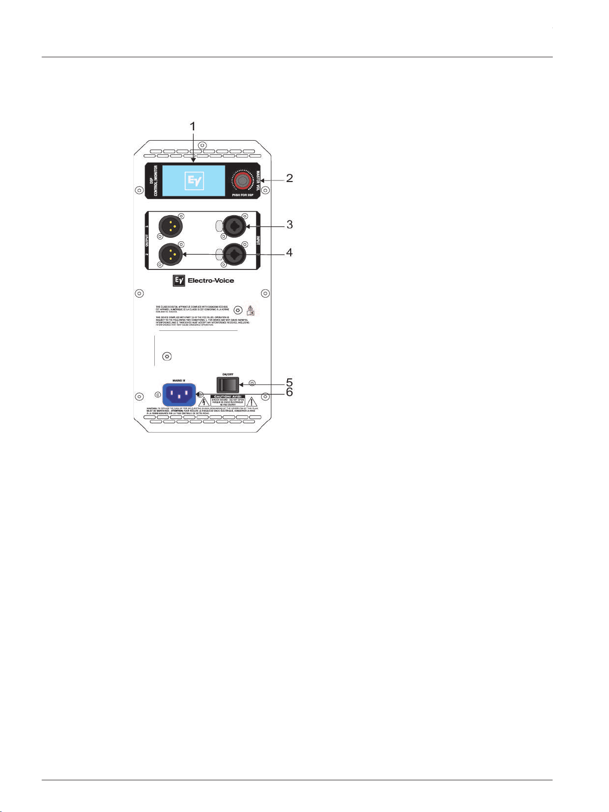
Subwoofer control and monitoring interface
The subwoofer DSP control menu selections are available for the ETX-15SP and ETX-18SP.
Figure 4.13: Subwoofer amplifier panel
1. LCD – DSP control and monitoring interface.
2. MASTER VOL – Adjusts the sound level.
DSP – Scroll through and select the available menu selections. Push and hold the
MASTER VOL knob to enter the DSP menu. For more information, see DSP controls, page
28.
3. INPUT – Balanced input for the connection of signal sources like mixing consoles,
instruments, or microphones. Connections can be established using ¼-inch TRS or XLR
connectors.
4. OUTPUT – XLR output sends the input signal to another loudspeaker or subwoofer.
INPUT 1 is linked to OUTPUT 1 and INPUT 2 is linked to OUTPUT 2. The MASTER VOL or
DSP control settings do not affect MIX OUTPUT.
5. POWER – AC switch or switching the power ON or OFF. The LCD screen lights up when
the POWER is turned ON.
6. MAINS IN – AC connection is established via an IEC-connector.
ETX Powered Loudspeakers
2014.07 | 04 | F.01U.276.083 User Manual Electro-Voice
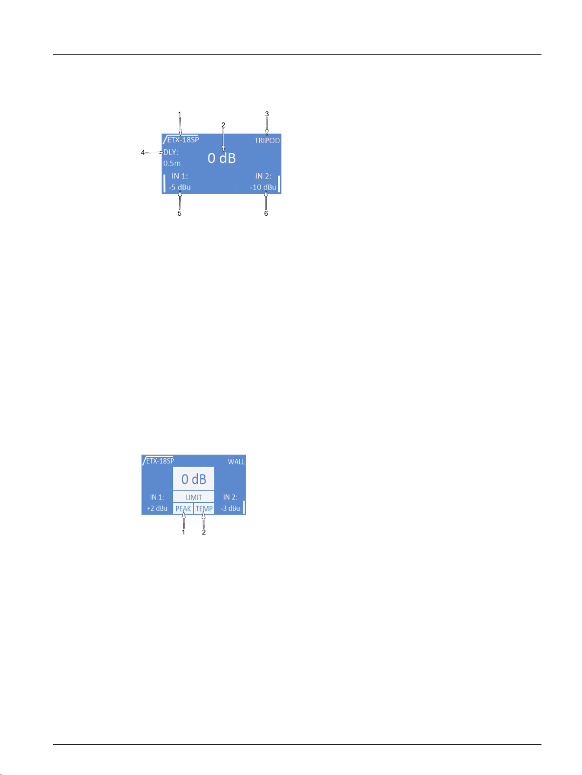
System status
Normal system status
Figure 4.14: Normal system status home screen
1. LOW PASS/HIGH PASS – Displays the high pass or low pass frequency of the system. For
full-range models, this indicates the high pass frequency selected. If no subwoofer is
used, the display indicates NO SUB. For subwoofer models, this indicates the low pass
frequency selected.
2. MASTER VOL – Indicates the master gain of the system. The range is from mute to +10
dB, in 1 dB increments.
3. LOCATION – Displays the location setting.
4. DLY (delay) – Displays the amount of delay.
5. INPUT 1 METER – Displays the signal level of INPUT 1 in dBu. The meter is post INPUT 1
gain control, but before MASTER VOL control. At signals above +18 dBu, the input
indicates CLIP.
6. INPUT 2 METER – Displays the signal level of INPUT 1 in dBu. The meter is post INPUT 2
gain control, but before MASTER VOL control. At signals above +18 dBu, the input
indicates CLIP.
System protection
Figure 4.15: System status limit
1. PEAK limiter – The peak anticipation limiter protects the loudspeaker from short-term
peaks which can cause distortion. Short-term blinking is not critical because the
integrated limiter keeps distortion under control. Constant lighting of PEAK indicates the
sound is negatively affected. Reducing the output volume (MASTER VOL) is strongly
recommended to reduce gain.
2. TEMP limiter – The temp limiter protects the transducer from thermal failures by
reducing the gain. The TEMP LIMITER will flash if any gain reduction is being done.
4.4
en 27
Electro-Voice User Manual 2014.07 | 04 | F.01U.276.083
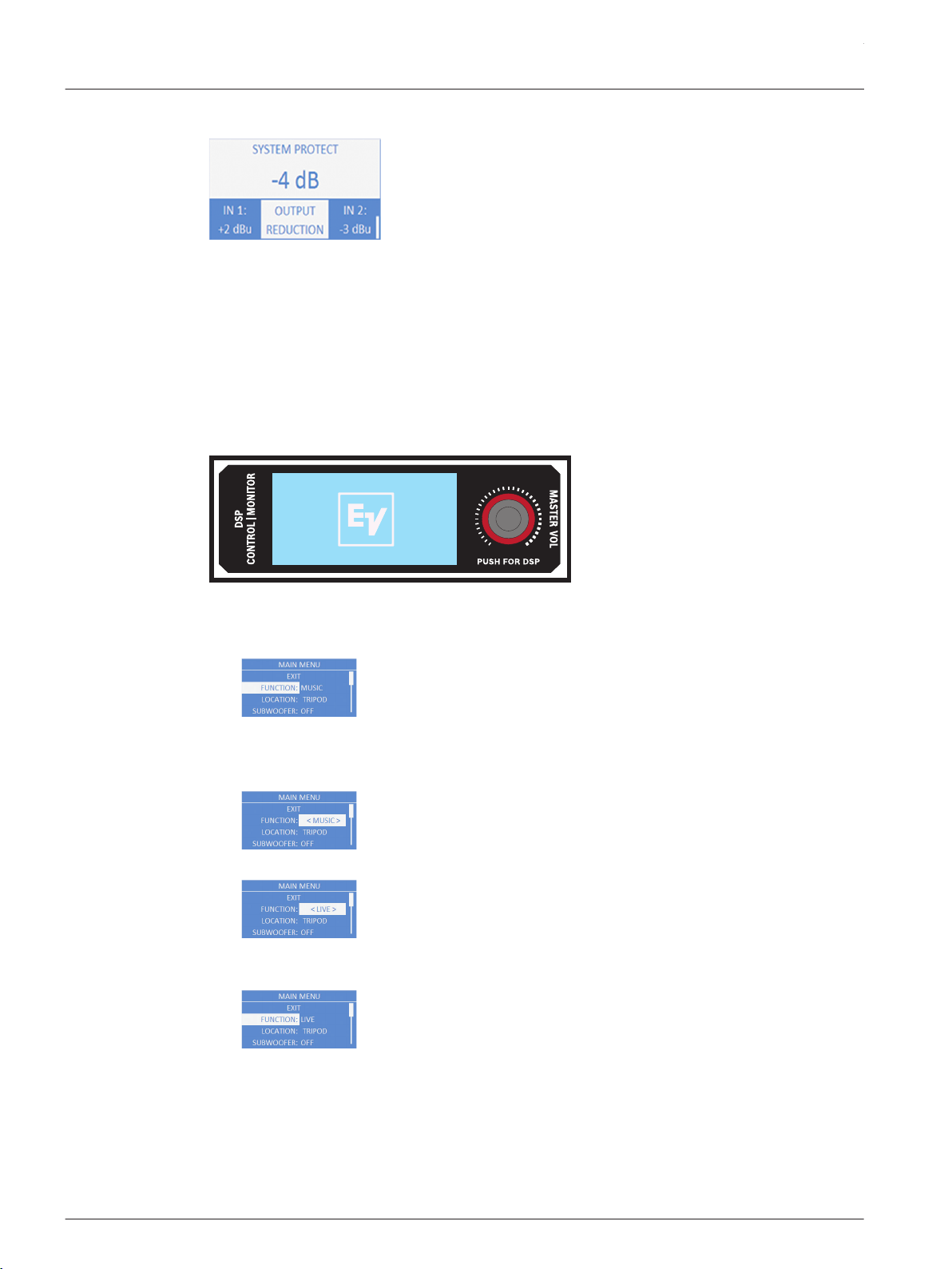
Output reduction
Figure 4.16: System protect
Under certain circumstances, the amplifier protects itself and reduces the output gain in order
prevent shutdown in adverse conditions. This may occur when the mains voltage is very low or
high, or when the ambient temperature is very high. The system returns to its original output if
the adverse conditions are corrected.
DSP controls
An integrated DSP control menu allows the user to select multiple DSP system settings on the
loudspeaker.
To access the DSP controls menu, do the following:
1. Push the MASTER VOL knob.
The DSP Control menu appears.
2. Using the MASTER VOL knob, scroll through the menu items.
3. Push the MASTER VOL knob to select the menu item you want to modify.
The focus moves to the menu items on the right side of the DSP menu.
4. Using the MASTER VOL knob, scroll through the menu items.
5. Push the MASTER VOL knob to confirm the selected menu items.
The setting is saved. The focus returns to the menu items on the left side of the DSP menu.
6. Repeat steps 2 through 5 to modify additional DSP and system settings.
7. Select EXIT to return to the home screen.
4.5
ETX Powered Loudspeakers
2014.07 | 04 | F.01U.276.083 User Manual Electro-Voice
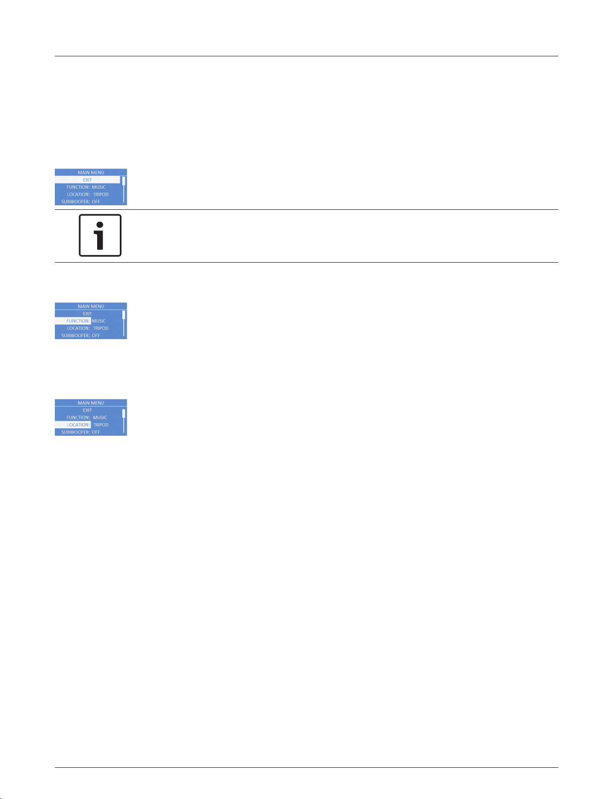
Full-Range loudspeaker DSP control menu
The full-range loudspeaker DSP control menu selections are available for the ETX-10P,
ETX-12P, ETX-15P, and ETX-35P loudspeakers.
EXIT Menu
The Exit menu is used to return to the home screen.
Notice!
The display returns to the home screen after two (2) minutes of inactivity.
FUNCTION Menu
The Function menu is used to configure the type of sound the loudspeaker delivers. Available
options for this selection are: MUSIC, LIVE, and SPEECH.
▪ MUSIC – is used for recorded music playback and EDM applications. (Default)
▪ LIVE – is used for live sound applications.
▪ SPEECH – is used for spoken word applications.
LOCATION Menu
The Location menu is used to optimize the loudspeaker for different boundaries.
ETX-10P, ETX-12P, and ETX-15P: Available options for this selection are: TRIPOD, MONITOR,
WALL, and SUSPEND. ETX-35P: Available options for this selection are: TRIPOD, ARRAY, WALL,
and SUSPEND.
▪ TRIPOD – is used when the loudspeaker is placed on a tripod stand or placed on a pole.
(Default)
▪ MONITOR – is used when the loudspeaker is placed on the angled monitor panel in
monitor position (Available for the ETX-10P, ETX-12P, and ETX-15P). This setting
compensates for the amount of low frequency boost created by placing the speaker close
to the floor.
▪ ARRAY – is used when the loudspeaker is part of an array, two (2) boxes side by side
using the array bracket kit (Available for the ETX-35P; Array Bracket Kit accessory sold
separately). This setting compensates for the effects of placing two (2) loudspeakers in
an array.
▪ WALL – is used when the loudspeaker is mounted to the wall using the mounting bracket
(Mounting Bracket accessory sold separately). This setting compensates for the amount
of low frequency boost created by placing the loudspeaker close to the wall. If used on a
column, it is recommended to use the SUSPEND mode.
▪ SUSPEND – is used when the loudspeaker is suspended in a 3-point suspension by
eyebolts. For more information, see Suspension, page 21.
4.5.1
en 29
Electro-Voice User Manual 2014.07 | 04 | F.01U.276.083
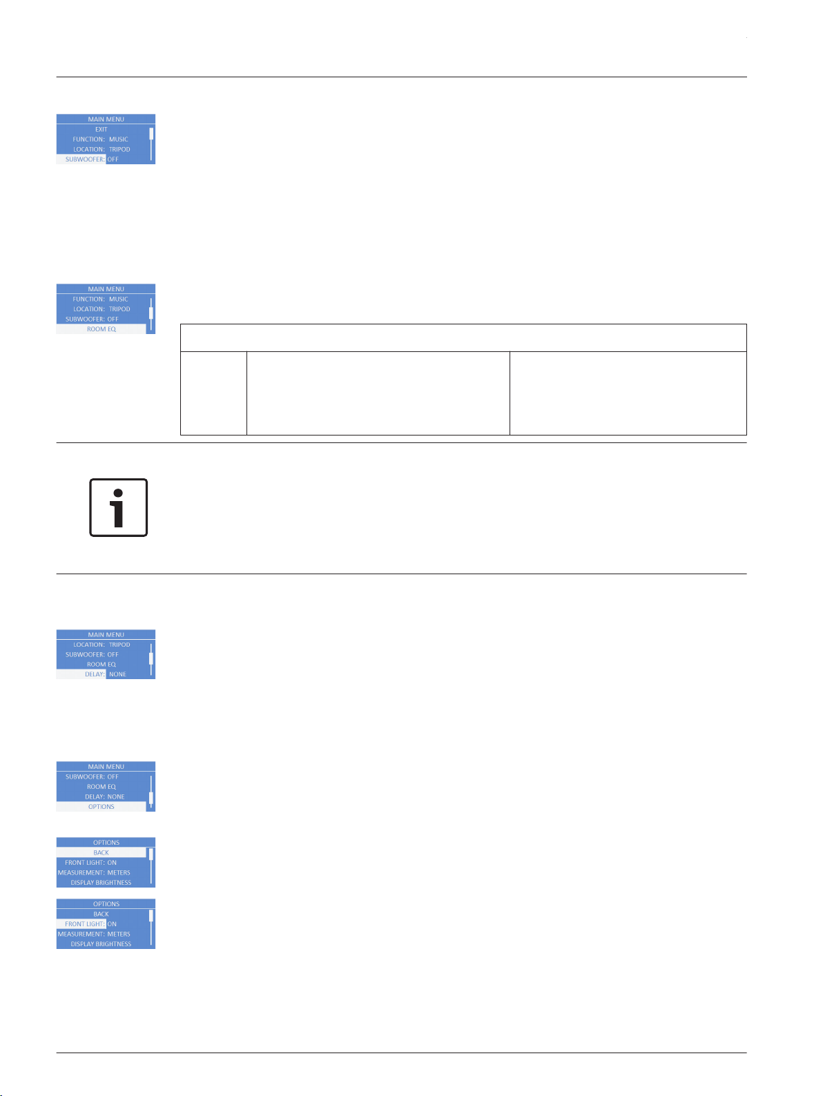
SUBWOOFER Menu
The Subwoofer menu is used to select a high pass frequency for use with a subwoofer or a
matched subwoofer. Available options for this selection are: OFF, 80Hz, 100Hz, 120Hz, 150Hz,
ETX-15SP, and ETX-18SP. The high passes are 24 dB/octave Linkwitz/Riley crossovers. The 80
Hz, 100 Hz, 120 Hz, and 150 Hz choices are generic high pass settings for use with other
subwoofers. The ETX-15SP and ETX-18SP settings are specifically optimized for subwoofers by
including delay for best summation.
The default is OFF.
ROOM EQ Menu
The Room EQ menu is a 3-band EQ (Equalizer) the user can fine tune beyond the FUNCTION
and LOCATION. Available options for this selection are: PEQ1, PEQ2, and PEQ3.
BACK
PEQ1,
PEQ2,
PEQ3:
ETX-10P Range: 60 Hz – 20.0 kHz
ETX-12P Range: 50 Hz – 20.0 kHz
ETX-15P Range: 45 Hz – 20.0 kHz
ETX-35P Range: 40 Hz – 20.0 kHz
Default: 0 dB
Range: -12 dB – +6 dB
Q: 1.2
Notice!
The Room EQ range shown is the factory default range with a stand alone loudspeaker. When
a subwoofer is selected, any EQ below the crossover point will be bypassed.
To use the EQ above the crossover point, do the following:
> Rotate the encoder to the desired frequency.
The BYPASS will be removed.
DELAY Menu
The Delay menu is used to create time alignment with other loudspeakers. Available options
for this selection are: NONE or a delay up to 343 m. The delay can be changed in 0.25 meter
increments. If the unit of measure is feet, available options for this selection are: NONE or a
delay up to 1125 ft. The delay can be changed in one (1) foot increments.
The default is NONE.
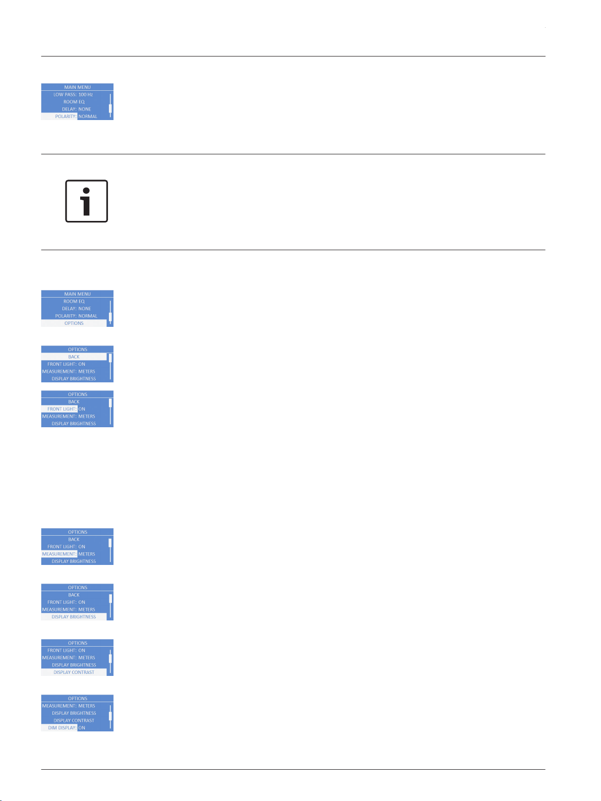
OPTIONS Menu
The Options menu is used to configure the DSP menu, LCD screen, and system. You can also
configure the accessibility of the menu as well as reset the modified settings to factory
default.
BACK Menu
The Back menu is used to return to the main menu.
FRONT LIGHT Menu
The Front Light menu shows power on and indicates limit. Available options for this selection
are: ON, OFF or LIMIT.
▪ ON – turns the LED on when the power to the loudspeaker is ON. (Default)
▪ OFF – turns the LED off.
ETX Powered Loudspeakers
2014.07 | 04 | F.01U.276.083 User Manual Electro-Voice
LIMIT – turns the LED off under normal operation. The LED brief blinking indicates the power
amplifier is operated at its limits. Short-term blinking is not critical because the integrated
limiter keeps distortion under control. Constant lighting of the LED indicates the sound is
negatively affected. Reducing the output volume is strongly recommended. For more
information see, System status, page 27.
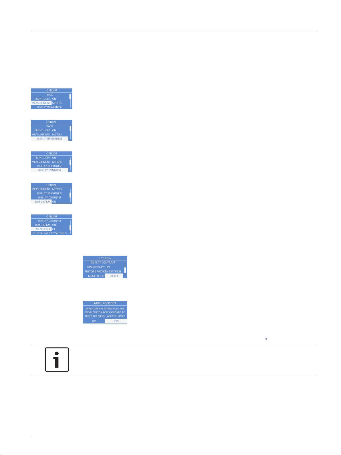
MEASUREMENT Menu
The Measurement menu is used to select the unit of measure for the delay. Available options
for this selection are: METERS or FEET.
The default is METERS.
DISPLAY BRIGHTNESS Menu
The Display Brightness menu is used to determine the brightness of the LCD. The range is 1
to 10.
The default is five (5).
DISPLAY CONTRAST Menu
The Display Contrast menu is used to determine the contrast on the LCD. The range is -10 to
+10.
The default is zero (0).
DIM DISPLAY Menu
The Dim Display menu is used to dim the display when the display is idle for two (2) minutes.
Available options for this selection are: ON or OFF.
The default is ON.
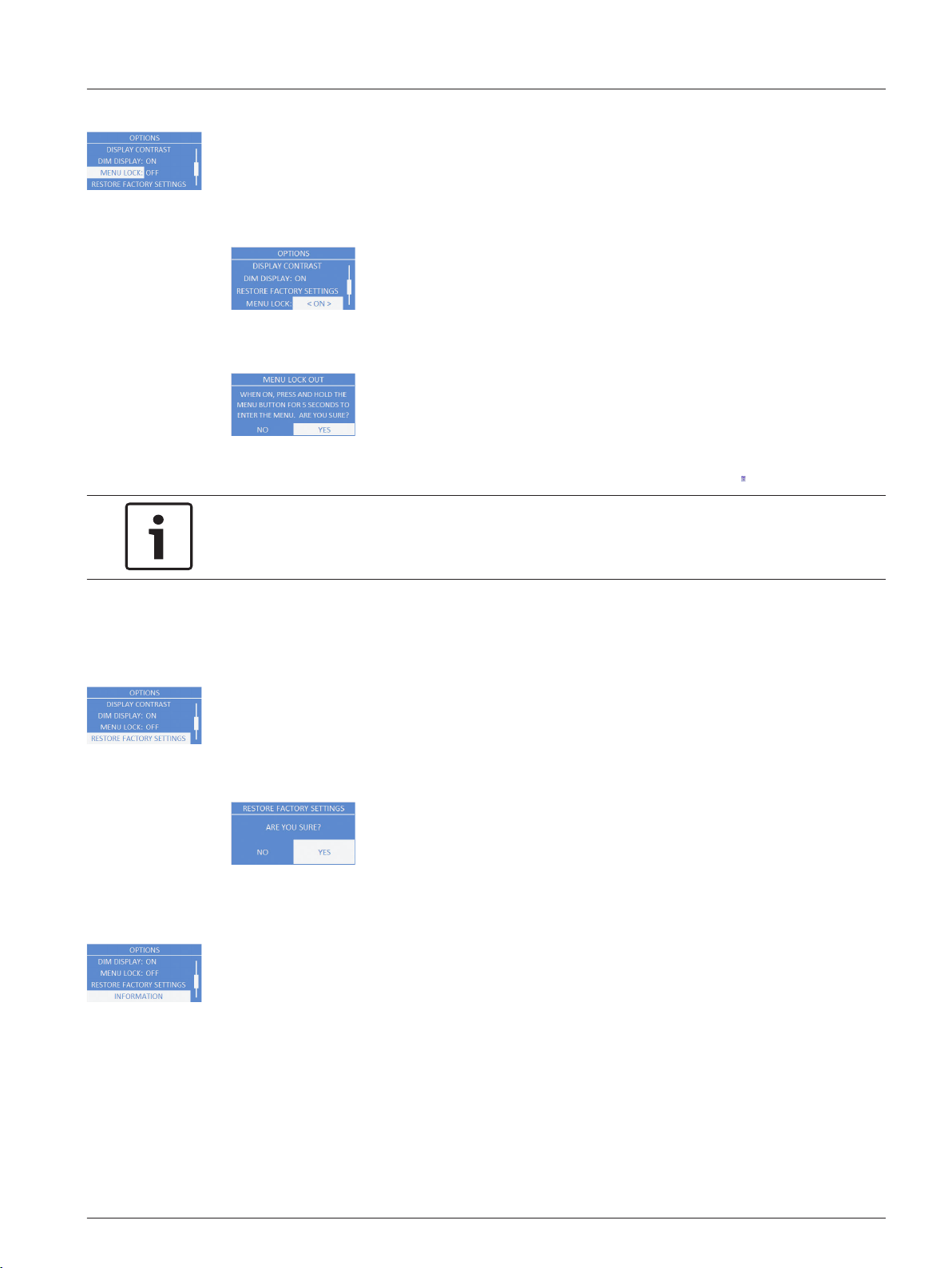
MENU LOCK Menu
The Menu Lock menu is designed to prevent users from inadvertently changing settings.
Available options for this selection are: ON or OFF.
The default is OFF.
To turn menu lock on, do the following:
1. From the DSP menu, scroll to MENU LOCK.
2. Select ON.
The Menu lock out message appears.
3. Select YES.
The menu lock feature is turned on and the LCD displays a lock symbol.
Notice!
If menu lock is ON, the user is allowed to adjust the MASTER VOL.
To unlock the DSP menu, do the following:
> Press and hold the MASTER VOL knob for 5 seconds.
The DSP menu unlocks.
en 31
Electro-Voice User Manual 2014.07 | 04 | F.01U.276.083
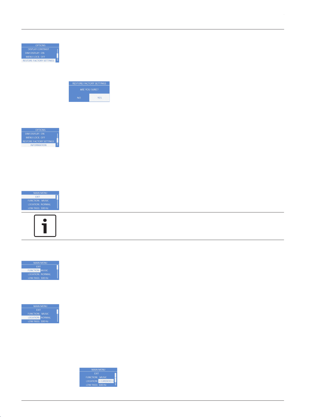
RESET FACTORY SETTTINGS Menu
The Reset Factory Settings menu is used to reset the loudspeaker to original factory settings.
Available options for this selection are: NO or YES. The default selection is NO.
To reset the system to original factory settings, do the following:
1. From the DSP menu, select RESET FACTORY SETTINGS.
The restore factory settings message appears.
2. Select YES.
The loudspeaker restarts and resets the system to the original factory settings.
INFORMATION Menu
The Information menu is used to display the preset version, firmware version, and build date.
Subwoofer DSP control menu
The subwoofer DSP control menu selections are available for the ETX-15SP and ETX-18SP
subwoofers.
EXIT Menu
The Exit menu is used to return to the home screen.
Notice!
The display returns to the home screen after two (2) minutes of inactivity.
FUNCTION Menu
The Function is used to configure the type of sound the subwoofer delivers. Available options
for this selection are: MUSIC and LIVE.
▪ MUSIC – is used for recorded music playback and EDM applications. (Default)
▪ LIVE – is used for live sound applications.
LOCATION Menu
The Location menu is used to control output of the subwoofer when used in arrays with other
subwoofers. Available options for this selection are: NORMAL and CARDIOID.
▪ NORMAL – is used for a single subwoofer, or an array of subwoofers where the desired
output is effectively omnidirectional. This setting should also be used for the front firing
subwoofers in a cardioid array. Under most circumstances, the subwoofer should be set
to NORMAL. (Default)
▪ CARDIOID – should ONLY be used on the rear firing subwoofers in cardioid arrays.
To set up cardioid, do the following:
1. From the DSP menu, scroll to LOCATION.
4.5.2
ETX Powered Loudspeakers
2014.07 | 04 | F.01U.276.083 User Manual Electro-Voice
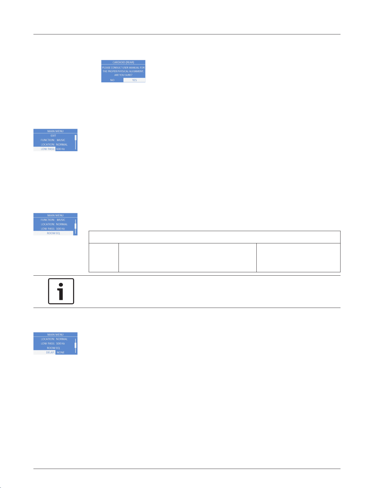
2. Select CARDIOID.
The CARDIOID (REAR)… message appears.
3. Select YES.
The location is set to cardioid. For more information, see Subwoofer cardioid array, page
39.
LOW PASS Menu
The Low Pass menu is used to select low pass frequency for proper summation with a
full-range loudspeaker. Available options for this selection are: 80 Hz, 100 Hz, 120 Hz, 150 Hz,
ETX-10P, ETX-12P, ETX-15P and ETX-35P. The low passes are 24 dB/octave Linkwitz/Riley
slopes. The 80 Hz, 100 Hz, 120 Hz, and 150 Hz selections are generic low pass settings for use
with other full-range loudspeaker systems. The ETX-10P, ETX-12P, ETX-15P, and ETX-35P
settings are specifically optimized for ETX Powered Loudspeaker by including delay for best
summation.
The default is 100 Hz.
ROOM EQ
The Room EQ menu is a single-band EQ the user can fine tune beyond the function and
location. Available option for this selection is: PEQ1.
BACK
PEQ1: Default: 50 Hz
ETX-15SP Range: 35 Hz to 100 Hz
ETX-18SP Range: 30 Hz to 100 Hz
Default: 0 dB
Range: -12 dB to +6 dB
Q: 2.0
Notice!
The Room EQ range shown is the factory default settings on a stand alone subwoofer. Room
EQ low frequency range is dependant on the low pass setting selected.
DELAY Menu
The Delay menu is used to create time alignment with other subwoofers. Available options for
this selection are: NONE or a delay up to 343 m. The delay can be changed in 0.25 meter
increments. If the unit of measure is feet, available options for this selection are: NONE or a
delay up to 1125 ft. The delay can be changed in one (1) foot increments.
The default is NONE.
en 33
Electro-Voice User Manual 2014.07 | 04 | F.01U.276.083
POLARITY Menu
The Polarity menu is used to change the polarity of the subwoofer system. Available options
for this selection are: NORMAL and REVERSE.
▪ NORMAL – A positive signal into the subwoofer produces a positive sound pressure.
(Default)
▪ REVERSE – A positive signal into the subwoofer produces a negative sound pressure.
Notice!
If one (1) subwoofer is set to NORMAL and another subwoofer is set to REVERSE, the output
of the subwoofers cancels acoustically.
Ensure all subwoofers in a system are set to the same polarity of the output so the
subwoofers sum properly. Under most circumstances, the polarity of the subwoofer should
be set to NORMAL.
OPTIONS Menu
The Options menu is used to configure the DSP menu, LCD screen, and system. You can also
configure the accessibility of the menu as well as reset the modified settings to factory
default.
BACK Menu
The Back menu is used to return to the main menu.
FRONT LIGHT Menu
The Front Light menu shows power on and indicates limit. Available options for this selection
are: ON, OFF or LIMIT.
▪ ON – turns the LED on when the power to the loudspeaker is ON. (Default)
▪ OFF – turns the LED off.
LIMIT – turns the LED off under normal operation. The LED brief blinking indicates the power
amplifier is operated at its limits. Short-term blinking is not critical because the integrated
limiter keeps distortion under control. Constant lighting of the LED indicates the sound is
negatively affected. Reducing the output volume is strongly recommended. For more
information see, System status, page 27.
MEASUREMENT Menu
The Measurement menu is used to select the unit of measure for the delay. Available options
for this selection are: METERS or FEET.
The default is METERS.
DISPLAY BRIGHTNESS Menu
The Display Brightness menu is used to determine the brightness of the LCD. The range is 1
to 10.
The default is five (5).
DISPLAY CONTRAST Menu
The Display Contrast menu is used to determine the contrast on the LCD. The range is -10 to
+10.
The default is zero (0).
DIM DISPLAY Menu
The Dim Display menu is used to dim the display when the display is idle for two (2) minutes.
Available options for this selection are: ON or OFF.
The default is ON.
ETX Powered Loudspeakers
2014.07 | 04 | F.01U.276.083 User Manual Electro-Voice
MENU LOCK Menu
The Menu Lock menu is designed to prevent users from inadvertently changing settings.
Available options for this selection are: ON or OFF.
The default is OFF.
To turn menu lock on, do the following:
1. From the DSP menu, scroll to MENU LOCK.
2. Select ON.
The Menu lock out message appears.
3. Select YES.
The menu lock feature is turned on and the LCD displays a lock symbol.
Notice!
If menu lock is ON, the user is allowed to adjust the MASTER VOL.
To unlock the DSP menu, do the following:
> Press and hold the MASTER VOL knob for 5 seconds.
The DSP menu unlocks.
RESET FACTORY SETTTINGS Menu
The Reset Factory Settings menu is used to reset the loudspeaker to original factory settings.
Available options for this selection are: NO or YES. The default selection is NO.
To reset the system to original factory settings, do the following:
1. From the DSP menu, select RESET FACTORY SETTINGS.
The restore factory settings message appears.
2. Select YES.
The loudspeaker restarts and resets the system to the original factory settings.
INFORMATION Menu
The Information menu is used to display the preset version, firmware version, and build date.
en 35
Electro-Voice User Manual 2014.07 | 04 | F.01U.276.083
Recommended configurations
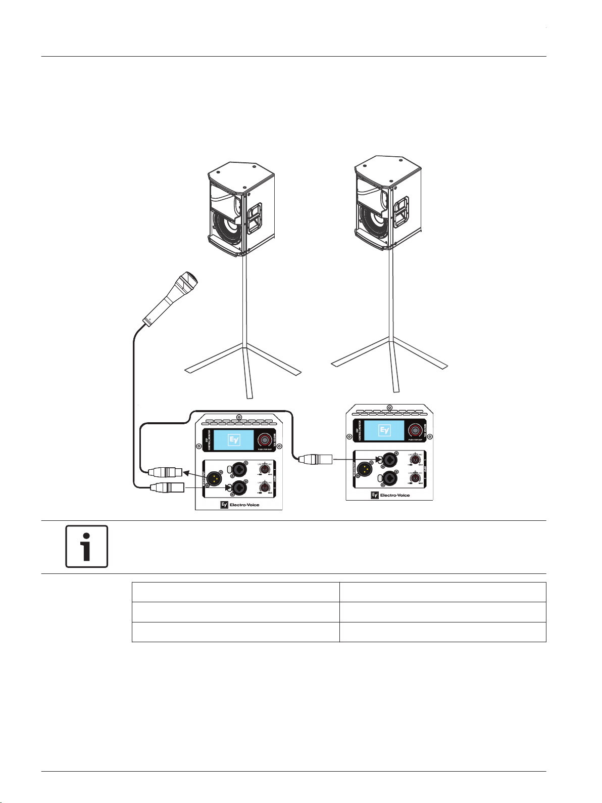
Daisy-chaining full-range systems
Vocal
Microphone
Notice!
The direction of the arrow indicates the signal path.
Location: Tripod
Function: Speech
Subwoofer: Off
Table 4.1: DSP settings loudspeaker on a tripod
For more information see, Full-Range loudspeaker DSP control menu, page 29.
4.6
4.6.1
ETX Powered Loudspeakers
2014.07 | 04 | F.01U.276.083 User Manual Electro-Voice
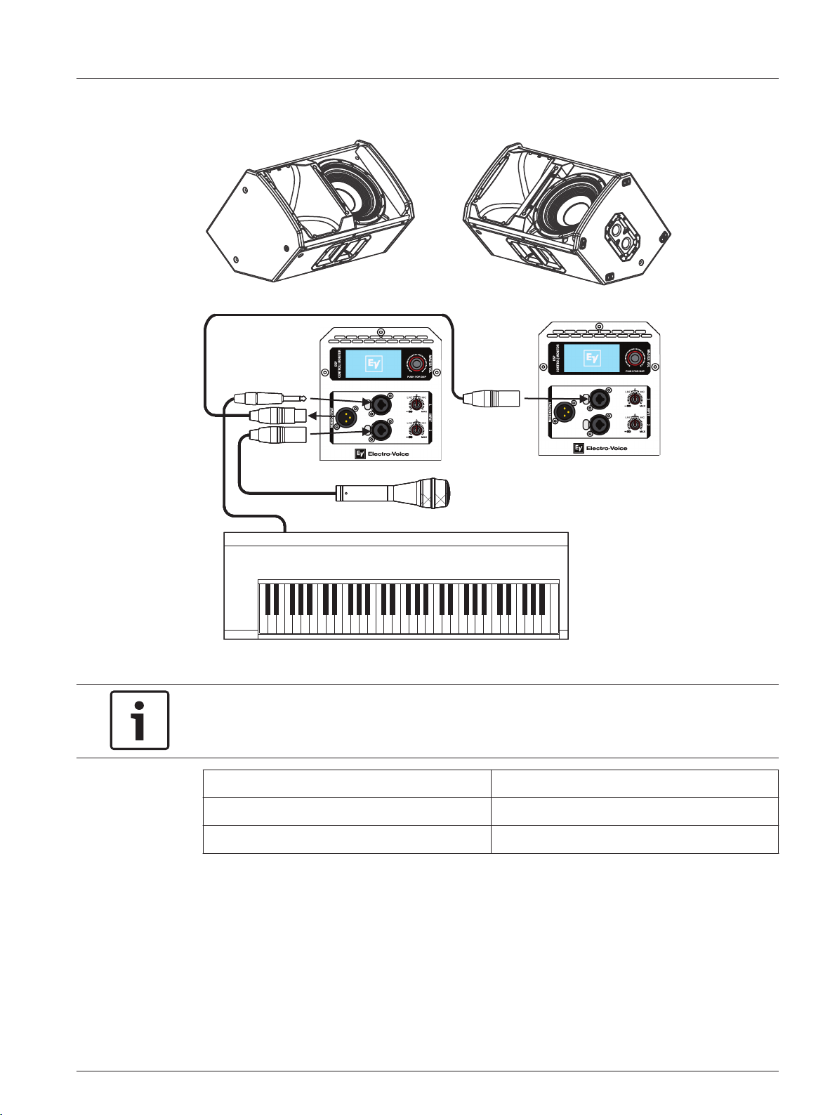
Using full-range systems as monitors
Vocal
Microphone
Instrument
Notice!
The direction of the arrow indicates the signal path.
Location: Monitor
Function: Live
Subwoofer: Off
Table 4.2: DSP settings loudspeaker as a monitor
For more information see, Full-Range loudspeaker DSP control menu, page 29.
4.6.2
en 37
Electro-Voice User Manual 2014.07 | 04 | F.01U.276.083
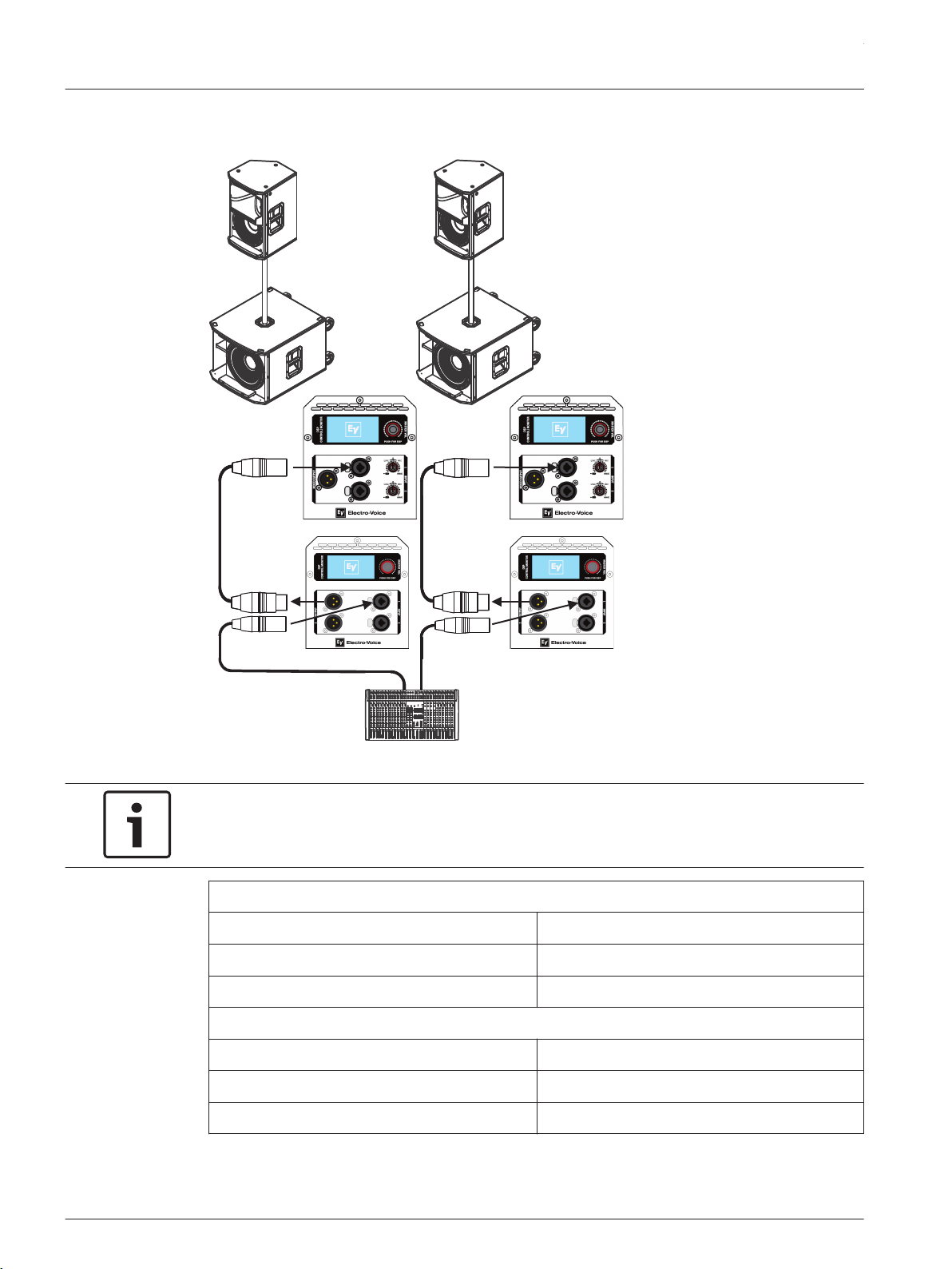
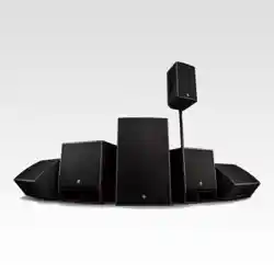
Stacking full-range systems with subwoofers
Mixer
ETX-12P
ETX-18SP
Notice!
The direction of the arrow indicates the signal path.
ETX-12P
Location: Tripod
Function: Live
Subwoofer: ETX-18SP
ETX-18SP
Location: Normal
Function: Live
High Pass: ETX-12P
Table 4.3: DSP settings loudspeaker and subwoofer stacked
4.6.3
ETX Powered Loudspeakers
2014.07 | 04 | F.01U.276.083 User Manual Electro-Voice
For more information, see Full-Range loudspeaker DSP control menu, page 29 and Subwoofer
DSP control menu, page 32.
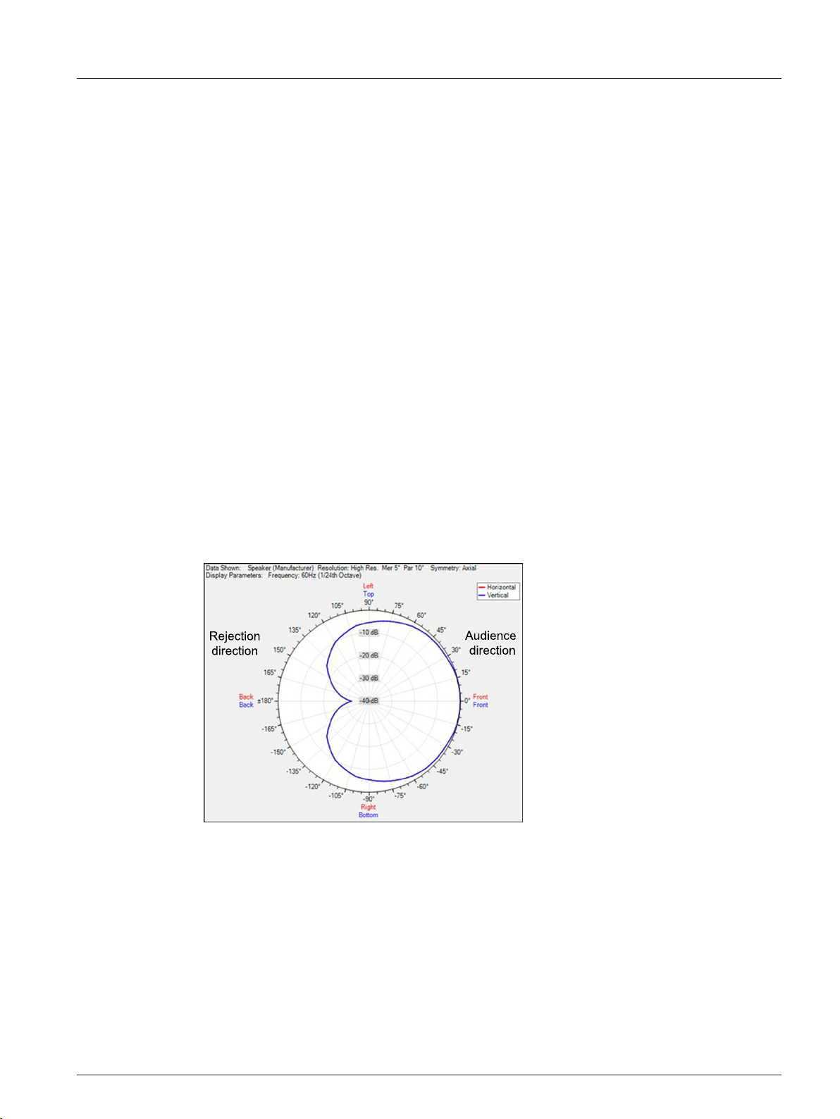
Subwoofer cardioid array
Subwoofer cardioid array
The ETX-15SP and ETX-18SP subwoofers have cardioid array processing originally developed
for Electro-Voice concert subwoofer systems. Cardioid subwoofer arrays can be used to direct
the output of an array of subwoofers in order to limit excessive amounts of bass in undesired
areas. These arrays can be used to keep bass off of a stage, provides more consistent bass
coverage in the audience, and reduces bass in the surrounding area.
Multiple ETX-15SP or ETX-18SP can be arrayed to create a cardioid polar pattern. See
Cardioid pattern top view. The cardioid setting in the DSP menu is optimized to produce a
rear rejection of up to 30 dB without any additional processing. The rejection may be less in
smaller indoor environments than in larger outdoor environments. For best performance,
adhere to the following guidelines:
▪ The subwoofers must all be the same model, for example all ETX-15SP or all ETX-18SP.
▪ The subwoofers must be physically placed in one (1) of the options shown. See Cardioid
physical alignment.
▪ Front firing subwoofers use the NORMAL location setting, and rear firing subwoofers use
the CARDIOID setting. All other settings should be the same between front and rear firing
subwoofers. For more information, see Subwoofer DSP control menu, page 32.
▪ To add delay to the cardioid array, add the same amount to both the front and rear facing
subwoofers. For more information, see Subwoofer DSP control menu, page 32.
Figure 4.17: Cardioid pattern top view
4.6.4
en 39
Electro-Voice User Manual 2014.07 | 04 | F.01U.276.083
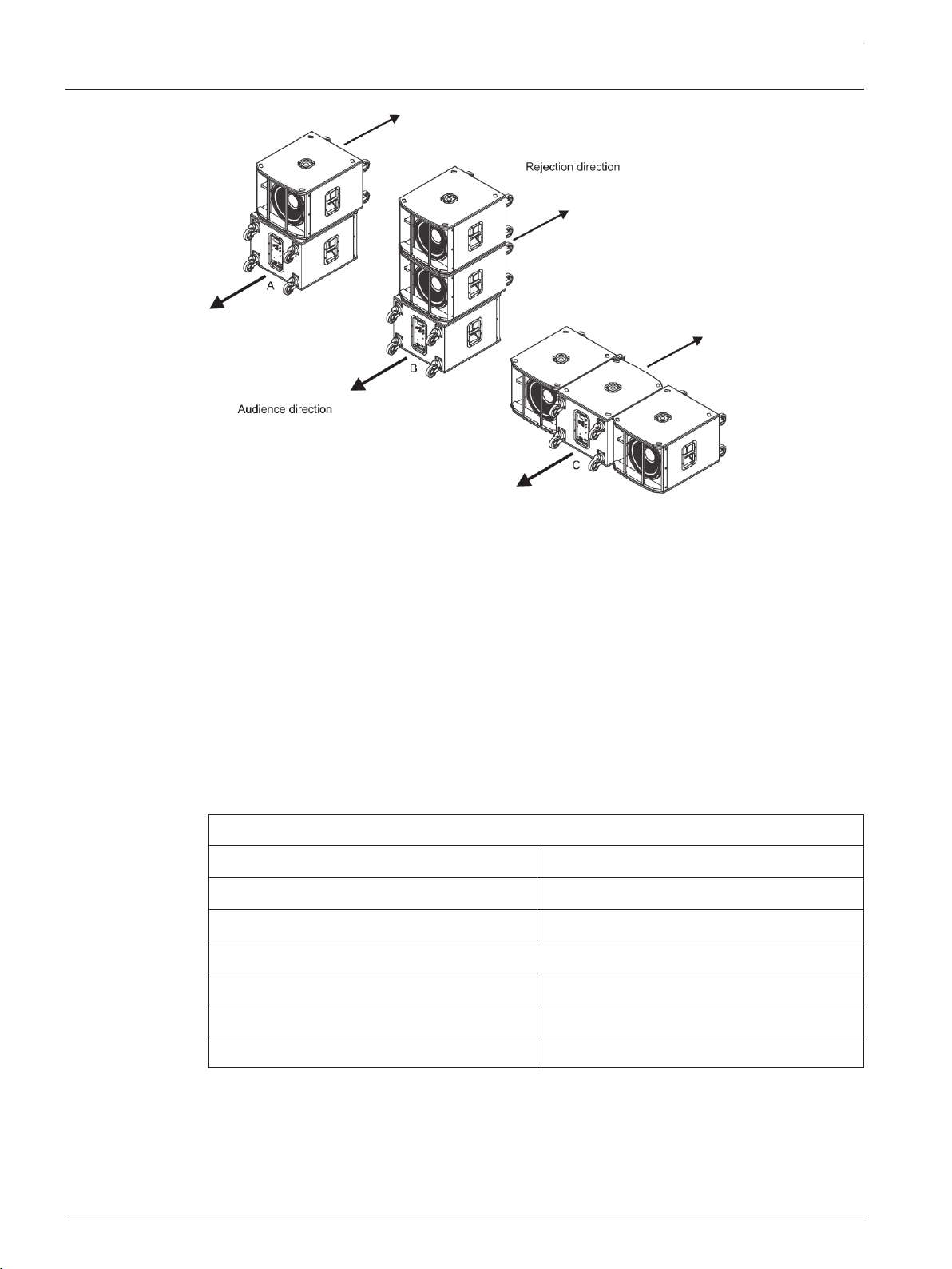
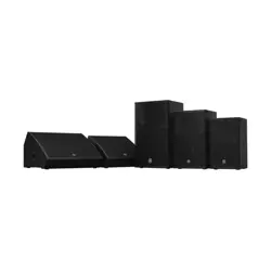
Figure 4.18: Cardioid physical alignment
Cardioid option A:
Either two (2) ETX-15SP or two (2) ETX-18SP subwoofers orientated vertically. Direct the top
subwoofer towards the audience and the bottom subwoofer away from the audience
(Rejection direction).
Cardioid option B:
Either three (3) ETX-15SP or three (3) ETX-18SP subwoofers orientated vertically. Direct the
top two (2) subwoofers towards the audience and the bottom subwoofer away from the
audience (Rejection direction).
Cardioid option C:
Either three (3) ETX-15SP or three (3) ETX-18SP subwoofers orientated horizontally. Direct
the left and right subwoofers towards the audience and the center subwoofer away from the
audience (Rejection direction).
Subwoofers facing the audience
Location: Normal
Polarity: Normal
Delay: 0 m (zero)
Subwoofers facing away from the audience (Rejection direction)
Location: Cardioid
Polarity: Normal
Delay: 0 m (zero)
Table 4.4: Subwoofer cardioid
For more information, see Subwoofer DSP control menu, page 32.
For more information about cardioid arrays, see ETX-15SP or ETX-18SP product pages on
www.electrovoice.com.
ETX Powered Loudspeakers
2014.07 | 04 | F.01U.276.083 User Manual Electro-Voice
Removing the subwoofer caster wheels
The ETX-15SP and ETX-18SP subwoofers have caster wheels attached for easy transportation
in portable applications. The caster wheels are removable for a permanent installation.
To remove the subwoofer caster wheels, do the following:
1. Remove the 16 M6 screws, 16 washers, and four (4) casters on the rear of the
subwoofer.
2. Install the 16 M6 screws and 16 washers back into the rear of the subwoofer.
Ensure all 16 M6 screws are tight.
Notice!
If the caster wheels are removed reinstall the screws.
If the screws are not reinstalled air leaks occur in the enclosure, resulting in undesirable
performance.
4.7
en 41
Electro-Voice User Manual 2014.07 | 04 | F.01U.276.083

Troubleshooting
Problem Possible Cause(s) Action
1. No Sound Amplifier Connect a known working test loudspeaker to the amplifier
outputs. If there is no sound, verify all the electronics are
on, the signal routing is correct, the source is active; the
volume is turned up, etc. Correct/repair/replace as
necessary. If there is sound, the problem is wiring.
Wiring Verify you have connected the correct cables to the
amplifier. Play something at a low level through the
amplifier. Connect the test loudspeaker in parallel with the
malfunctioning line. If the sound level is gone or is very
weak, the line has a short in it (possibly a severe scrape,
pinch, or a missed connection). Using the test loudspeaker,
move down the line and test each connection/junction until
you find the problem and correct it. Observe proper
polarity.
2. Poor
Low-
Frequency
Response
With SUB menu-
cross-over frequency
activated
If no subwoofers are used with the system, select the OFF
position. For more information, see Full-Range loudspeaker
DSP control menu, page 29.
3. Intermittent
output such
as cracking or
distortion
Faulty Connection Check all connections at amplifier and loudspeakers to
ensure they are all clean and tight. If the problem persists,
check the wiring. See problem 1.
4. Constant
noise such as
buzzing,
hissing or
humming
Defective source or
other electronic
device
If noise is present, but no program material is playing,
evaluate each component as necessary to isolate the
problem. Most likely there is a break in the signal path.
Poor system
grounding or ground
loop
Check and correct the system grounding, as required.
Input gain knob is
not in the MIC
position
Slowly increase the input gain knob level to engage the
microphone pre-amp.
5. No sound
produced with
microphone
connected to
INPUT 1 or
INPUT 2
Microphone requires
phantom power
Use a dynamic microphone that does not require phantom
power. If using a microphone requiring phantom power, an
external phantom power source is needed.
Input gain knob is
not in the MIC
position
Slowly increase the input gain knob level to engage the
microphone pre-amp.
6. Sound is
distorted front
LED is OFF,
LCD screen
LIMIT is ON
Excessive input level Reduce the input level or loudspeaker level knobs to
prevent limit.
5
ETX Powered Loudspeakers
2014.07 | 04 | F.01U.276.083 User Manual Electro-Voice

Problem Possible Cause(s) Action
Incorrect gain
structure or source
input (mixing
console/preamp) is
overdriven
Verify level controls of the source are properly structured
by using the VU meter indicator on the LCD screen. If the
VU meter bar is solid or the system indicates LIMIT, the
input or source level is too high. Fore more information,
see System status, page 27.
7. Microphone
produces
acoustic
feedback
when input
level is
amplified
Incorrect gain
structure
Reduce the microphone levels at the mixing console or
input source. If the microphone is connected directly to the
speaker, reduce the input level on the speaker. Positioning
the microphone close to the sound source increases gain-
before-feedback. See problem 6.
FUNCTION is set to
MUSIC
Change the LOCATION to LIVE or SPEECH. For more
information, see Full-Range loudspeaker DSP control menu,
page 29.
Microphone position
is too close to the
front of the
loudspeaker
Whenever possible setup the loudspeakers so the
microphone is behind them. If using the loudspeaker in a
monitor position, aim the loudspeaker to the back of the
microphone.
8. DSP menu is
locked.
The Menu Lock
function has been
turned on. A lock
symbol displays on
the LCD screen.
Press and hold the MASTER VOL knob for 5 seconds. For
more information, see MENU LOCK Menu, page 31.
If these suggestions do not solve your problem, contact your nearest Electro-Voice dealer or
Electro-Voice distributor.
en 43
Electro-Voice User Manual 2014.07 | 04 | F.01U.276.083

Bosch Security Systems, Inc
12000 Portland Avenue South
Burnsville MN 55337
USA
www.electrovoice.com
© Bosch Security Systems, Inc, 2014