Projector
PX803UL-WH/PX803UL-BK
User’s Manual
Model No.
NP-PX803UL-WH/NP-PX803UL-BK

Ver. 1 11/15
• Apple,Mac,MacOS,andMacBookaretrademarksofAppleInc.registeredintheU.S.andothercountries.
• Microsoft,Windows,WindowsVista,Internet Explorer,.NETFrameworkandPowerPointareeitheraregistered
trademarkortrademarkofMicrosoftCorporationintheUnitedStatesand/orothercountries.
• MicroSaverisaregisteredtrademarkofKensingtonComputerProductsGroup,adivisionofACCOBrands.
• Adobe,AdobePDF,AdobeReader,andAcrobatareeitherregisteredtrademarksortrademarksofAdobeSystems
IncorporatedintheUnitedStatesand/orothercountries.
• VirtualRemoteToolusesWinI2C/DDClibrary,©NicomsoftLtd.
• HDMI,theHDMILogoandHigh-DenitionMultimediaInterfacearetrademarksorregisteredtrademarksofHDMI
LicensingLLC.
• DisplayPortandDisplayPortComplianceLogoaretrademarksownedbytheVideoElectronicsStandardsAssocia-
tion.
• HDBaseT™isatrademarkofHDBaseTAlliance.
• DLPandBrilliantColoraretrademarksofTexasInstruments.
• TrademarkPJLinkisatrademarkappliedfortrademarkrightsinJapan,theUnitedStatesofAmericaandother
countriesandareas.
• Wi-Fi
®
,Wi-FiAlliance
®
,andWi-FiProtectedAccess(WPA,WPA2)
®
areregisteredtrademarksoftheWi-FiAlliance.
• Blu-rayisatrademarkofBlu-rayDiscAssociation
• CRESTRONandROOMVIEWareregisteredtrademarksofCrestronElectronics,Inc.intheUnitedStatesandother
countries.
• EthernetiseitheraregisteredtrademarkortrademarkofFujiXeroxCo.,Ltd.
• ExtronandXTPareregisteredtrademarksofRGBSystems,Inc.intheUnitedStates.
• Otherproductandcompanynamesmentionedinthisuser’smanualmaybethetrademarksorregisteredtrademarks
oftheirrespectiveholders.
• TOPPERSSoftwareLicenses
TheproductincludessoftwarelicensedunderTOPPERSLicense.
Formoreinformationoneachsoftware,see“readme.pdf”insidethe“aboutTOPPERS”folderonthesuppliedCD-
ROM.
NOTES
(1)Thecontentsofthisuser’smanualmaynotbereprintedinpartorwholewithoutpermission.
(2)Thecontentsofthisuser’smanualaresubjecttochangewithoutnotice.
(3)Greatcarehasbeentakeninthepreparationofthisuser’smanual;however,shouldyounoticeanyquestionable
points,errorsoromissions,pleasecontactus.
(4)Notwithstandingarticle(3),NECwillnotberesponsibleforanyclaimsonlossofprotorothermattersdeemed
toresultfromusingtheProjector.
i
Important Information
Safety Cautions
Precautions
PleasereadthismanualcarefullybeforeusingyourNECprojectorandkeepthemanualhandyforfuturereference.
CAUTION
Toturnoffmainpower,besuretoremovetheplugfrompoweroutlet.
Thepoweroutletsocketshouldbeinstalledasneartotheequipmentaspossible,andshouldbeeasily
accessible.
CAUTION
TOPREVENTSHOCK,DONOTOPENTHECABINET.
THEREAREHIGH-VOLTAGECOMPONENTSINSIDE.
REFERSERVICINGTOQUALIFIEDSERVICEPERSONNEL.
Thissymbolwarnstheuserthatuninsulatedvoltagewithintheunitmaybesufcienttocauseelectrical
shock.Therefore,itisdangeroustomakeanykindofcontactwithanypartinsideoftheunit.
Thissymbolalertstheuserthatimportantinformationconcerningtheoperationandmaintenanceofthis
unithasbeenprovided.
Theinformationshouldbereadcarefullytoavoidproblems.
WARNING:TOPREVENTFIREORSHOCK,DONOTEXPOSETHISUNITTORAINORMOISTURE.
DONOTUSETHISUNIT’SPLUGWITHANEXTENSIONCORDORINANOUTLETUNLESSALLTHEPRONGS
CANBEFULLYINSERTED.
DOC Compliance Notice (for Canada only)
ThisClassAdigitalapparatuscomplieswithCanadianICES-003.
Machine Noise Information Regulation - 3. GPSGV,
Thehighestsoundpressurelevelislessthan70dB(A)inaccordancewithENISO7779.
Disposing of your used product
EU-widelegislationasimplementedineachMemberStaterequiresthatusedelectricalandelectronicprod-
uctscarryingthemark(left)mustbedisposedofseparatelyfromnormalhouseholdwaste.Thisincludes
projectorsandtheirelectricalaccessories.Whenyoudisposeofsuchproducts,pleasefollowtheguidance
ofyourlocalauthorityand/orasktheshopwhereyoupurchasedtheproduct.
Aftercollectingtheusedproducts,theyarereusedandrecycledinaproperway.Thiseffortwillhelpusreduce
thewastesaswellasthenegativeimpacttothehumanhealthandtheenvironmentattheminimumlevel.
ThemarkontheelectricalandelectronicproductsonlyappliestothecurrentEuropeanUnionMemberStates.
For EU:Thecrossed-outwheeledbinimpliesthatusedbatteriesshouldnotbeputtothegeneralhousehold
waste!Thereisaseparatecollectionsystemforusedbatteries,toallowpropertreatmentandrecyclingin
accordancewithlegislation.
According the EU directive 2006/66/EC, the battery can’t be disposed improperly. The battery shall be sepa-
rated to collect by local service.

ii
Important Information
WARNING TO CALIFORNIA RESIDENTS:
Handlingthecablessuppliedwiththisproductwillexposeyoutolead,achemicalknowntotheStateofCalifornia
tocausebirthdefectsorotherreproductiveharm.WASHHANDSAFTERHANDLING.
RF Interference
WARNING
ThisisaClassAproduct.Inadomesticenvironmentthisproductmaycauseradiointerferenceinwhichcasethe
usermayberequiredtotakeadequatemeasures.
CAUTION
• Inordertoreduceanyinterferencewithradioandtelevisionreceptionuseasignalcablewithferritecoreattached.
Useofsignalcableswithoutaferritecoreattachedmaycauseinterferencewithradioandtelevisionreception.
• ThisequipmenthasbeentestedandfoundtocomplywiththelimitsforaClassAdigitaldevice,pursuanttoPart
15oftheFCCRules.Theselimitsaredesignedtoprovidereasonableprotectionagainstharmfulinterference
whentheequipmentisoperatedinacommercialenvironment.Thisequipmentgenerates,uses,andcanradi-
ateradiofrequencyenergyand,ifnotinstalledandusedinaccordancewiththeinstallationmanual,maycause
harmfulinterferencetoradiocommunications.Operationofthisequipmentinaresidentialareaislikelytocause
harmfulinterferenceinwhichcasetheuserwillberequiredtocorrecttheinterferenceathisownexpense.
ForUKonly:InUK,aBSapprovedpowercordwithmouldedplughasaBlack(veAmps)fuseinstalledforusewith
thisequipment.Ifapowercordisnotsuppliedwiththisequipmentpleasecontactyoursupplier.
Important Safeguards
Thesesafetyinstructionsaretoensurethelonglifeofyourprojectorandtopreventreandshock.Pleasereadthem
carefullyandheedallwarnings.
WARNING
• Whentheprojectorisdamaged,coolinguidsmaycomeoutofinternalpart.
Shouldthishappen,immediatelyturnofftheACsupplytotheprojectorandcontactyourdealer.
DONOTtouchanddrinkthecoolinguid.Whenthecoolinguidsareswallowedorcontactedwithyour
eyes,pleaseconsultmedicalattentionimmediately.Ifyoutouchthecoolinguidwithyourhand,rinse
yourhandswellunderrunningwater.
Installation
• Donotplacetheprojectorinthefollowingconditions:
- onanunstablecart,stand,ortable.
- nearwater,baths,ordamprooms.
- indirectsunlight,nearheaters,orheatradiatingappliances.
- inadusty,smokyorsteamyenvironment.
- onasheetofpaperorcloth,rugsorcarpets.
• Donotinstallandstoretheprojectorinthebelowcircumstances.Failuretodosomaycauseofmalfunction.
- Inpowerfulmagneticelds
- Incorrosivegasenvironment
- Outdoors
• Ifyouwishtohavetheprojectorinstalledontheceiling:
- Donotattempttoinstalltheprojectoryourself.
- Theprojectormustbeinstalledbyqualiedtechniciansinordertoensureproperoperationandreducetherisk
ofbodilyinjury.
- Inaddition,theceilingmustbestrongenoughtosupporttheprojectorandtheinstallationmustbeinaccordance
withanylocalbuildingcodes.
- Pleaseconsultyourdealerformoreinformation.
iii
Important Information
WARNING
• Donotuseanyotherobjectthantheprojector’slenscovertocoverthelenswhiletheprojectorison.Doingso
cancausetheobjecttogetextremelyhot,andpossiblyresultinginareordamageduetotheheatemitted
fromthelightoutput.
• Donotplaceanyobjects,whichareeasilyaffectedbyheat,infrontoftheprojectorlens.Doingsocouldlead
totheobjectmeltingfromtheheatthatisemittedfromthelightoutput.
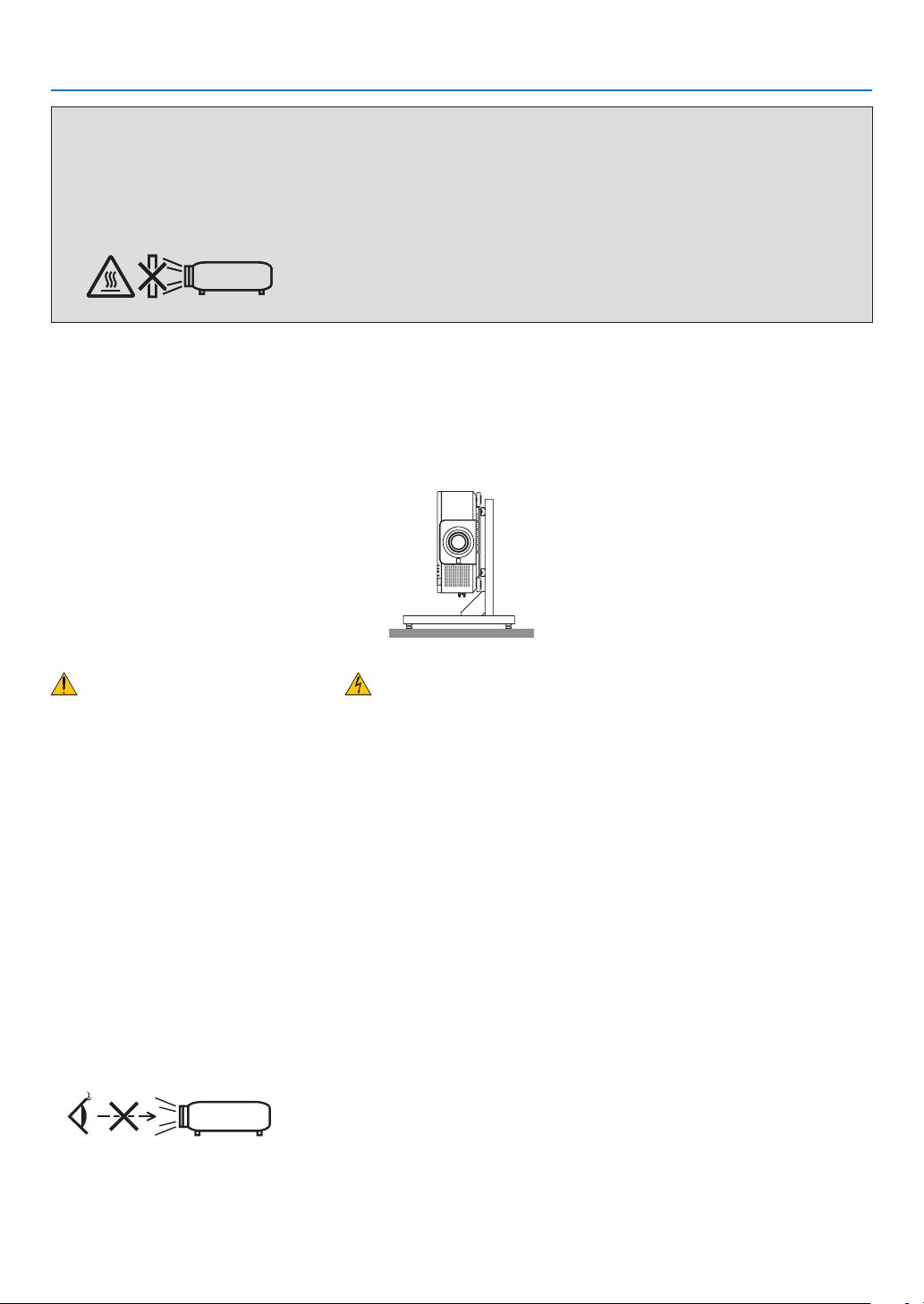
Thisprojectorcanbeinstalledanyanglewithinverticalandhorizontal360°range,however,lifeofopticalpartswill
beshorteninthefollowinginstallationstate:
• Whentheprojectorisinstalledonwhichlensfacesdownward.
• Whentheintakeventontheprojectorsidefacesdownwardintheportraitinstallation.(→page154)
Forportraitinstallation,installtheprojectorwiththeintakeventatthebottom.Observeprecautionsforportraitinstallation.
* Acustomizedstandisrequiredtobeattachedtotheprojector.(→page155)
Fire and Shock Precautions
• Ensurethatthereissufcientventilationandthatventsareunobstructedtopreventthebuild-upofheatinsideyour
projector.Allowenoughspacebetweenyourprojectorandawall.(→pagexi)
• Donottrytotouchtheexhaustventontherearside(whenseenfromthefront)asitcanbecomeheatedwhilethe
projectoristurnedonandimmediatelyaftertheprojectoristurnedoff.Partsoftheprojectormaybecometemporarily
heatediftheprojectoristurnedoffwiththePOWERbuttonoriftheACpowersupplyisdisconnectedduringnormal
projectoroperation.
Usecautionwhenpickinguptheprojector.
• Preventforeignobjectssuchaspaperclipsandbitsofpaperfromfallingintoyourprojector.Donotattempttoretrieve
anyobjectsthatmightfallintoyourprojector.Donotinsertanymetalobjectssuchasawireorscrewdriverintoyour
projector.Ifsomethingshouldfallintoyourprojector,disconnectitimmediatelyandhavetheobjectremovedbya
qualiedservicepersonnel.
• Donotplaceanyobjectsontopoftheprojector.
• Donottouchthepowerplugduringathunderstorm.Doingsocancauseelectricalshockorre.
• Theprojectorisdesignedtooperateonapowersupplyof100-240VAC50/60Hz.Ensurethatyourpowersupply
tsthisrequirementbeforeattemptingtouseyourprojector.
• Donotlookintothelenswhiletheprojectorison.Seriousdamagetoyoureyescouldresult.
• Donotlookintothelightsourceusingopticalinstruments(suchasmagnifyingglassesandmirrors).Visualimpair-
mentcouldresult.
• Whenturningontheprojector,ensurethatnobodyisfacingtowardsthelensinthepathofthelightemittedfrom
thelaser.
• Keepanyitems(magnifyingglassetc.)outofthelightpathoftheprojector.Thelightpathbeingprojectedfromthe
lensisextensive,thereforeanykindofabnormalobjectsthatcanredirectlightcomingoutofthelens,cancause
anunpredictableoutcomesuchasareorinjurytotheeyes.
• Donotplaceanyobjects,whichareeasilyaffectedbyheat,infrontofaprojectorexhaustvent.
Doingsocouldleadtotheobjectmeltingorgettingyourhandsburnedfromtheheatthatisemittedfromtheexhaust
vent.

iv
Important Information
• Handlethepowercordcarefully.Adamagedorfrayedpowercordcancauseelectricshockorre.
- Donotuseanypowercordotherthantheonesuppliedwiththeprojector.
- Donotbendortugthepowercordexcessively.
- Donotplacethepowercordundertheprojector,oranyheavyobject.
- Donotcoverthepowercordwithothersoftmaterialssuchasrugs.
- Donotheatthepowercord.
- Donothandlethepowerplugwithwethands.
• Turnofftheprojector,unplugthepowercordandhavetheprojectorservicedbyaqualiedservicepersonnelunder
thefollowingconditions:
- Whenthepowercordorplugisdamagedorfrayed.
- Ifliquidhasbeenspilledintotheprojector,orifithasbeenexposedtorainorwater.
- Iftheprojectordoesnotoperatenormallywhenyoufollowtheinstructionsdescribedinthisuser’smanual.
- Iftheprojectorhasbeendroppedorthecabinethasbeendamaged.
- Iftheprojectorexhibitsadistinctchangeinperformance,indicatinganeedforservice.
• Disconnectthepowercordandanyothercablesbeforecarryingtheprojector.
• Turnofftheprojectorandunplugthepowercordbeforecleaningthecabinet.
• Turnofftheprojectorandunplugthepowercordiftheprojectorisnottobeusedforanextendedperiodoftime.
• WhenusingaLANcable:
Forsafety,donotconnecttotheterminalforperipheraldevicewiringthatmighthaveexcessivevoltage.
• Donotusethemalfunctionedprojector.Itmaycauseofnotonlyelectricshockorrebutalsoseriousdamageto
youreyesight.
• Donotletchildrentooperatetheprojectorbythemselves.Iftheprojectorisoperatedbychildren,adultsneedto
attendandkeeptheireyesonchildren.
• Ifdamageormalfunctionoftheprojectorisfound,immediatelystoptouseitandconsultyourdealerforrepair.
• Neverdisassemble,repair,andremodelbyendusers.Iftheseareperformedbyendusers,itmaycauseofserious
problemonusers’safety.
• Consultyourdealerfordisposingtheprojector.Neverdisassembletheprojectorbeforedisposingit.
CAUTION
• Keephandsawayfromthelensmountingportionwhileperformingalensshift.Failuretodosocouldresultin
ngersbeingpinchedbythemovinglens.
• Donotusethetilt-footforpurposesotherthanoriginallyintended.Misusessuchasgrippingthetilt-footorhang-
ingonthewallcancausedamagetotheprojector.
• Donotsendtheprojectorinthesoftcasebyparceldeliveryserviceorcargoshipment.Theprojectorinsidethe
softcasecouldbedamaged.
• Select[HIGH]inFanmodeifyoucontinuetousetheprojectorforconsecutivedays.(Fromthemenu,select
[SETUP]→[OPTIONS(1)]→[FANMODE]→[MODE]→[HIGH].)
• Donotunplugthepowercordfromthewalloutletorprojectorwhentheprojectorispoweredon.Doingsocan
causedamagetotheACINterminaloftheprojectorand(or)theprongplugofthepowercord.
ToturnofftheACpowersupplywhentheprojectorispoweredon,usetheprojector’smainpowerswitch,apower
stripequippedwithaswitch,orabreaker.
• Whenmovingtheprojector,makesureyouhaveatleasttwopeople.Attemptingtomovetheprojectoralone
couldresultinbackpainorotherinjuries.
Caution on Handling the Optional Lens
Whenshippingtheprojectorwiththelens,removethelensbeforeshippingtheprojector.Alwaysattachthedustcap
tothelenswheneveritisnotmountedontheprojector.Thelensandthelensshiftmechanismmayencounterdamage
causedbyimproperhandlingduringtransportation.
Donotholdthelenspartwhencarryingtheprojector.
Doingsocouldcausethefocusringtorotate,resultinginaccidentaldroppingoftheprojector.
Formounting,replacing,andcleaningthelens,makesuretopowerofftheprojectoranddisconnectthepowercord.
Failuretodosocanresultineyeinjury,electricshock,orburninjuries.

v
Important Information
Precautions when installing or replacing the lens unit sold separately (LENS
CALIBRATION)
Afterinstallingorreplacingthelensunit,presseithertheSHUTTER/CALIBRATIONbuttononthemainunitorthe
INFO/L-CALIB.buttonwhilepressingtheCTLbuttonontheremotecontroltocarryout[LENSCALIBRATION].(→
page18,118)
Bycarryingout[LENSCALIBRATION],theadjustmentrangeofthezoom,focus,andshiftofthe[LENSMEMORY]
iscalibrated.
Contactyourdealertoinstallandreplacethelensunit.
Remote Control Precautions
• Handletheremotecontrolcarefully.
• Iftheremotecontrolgetswet,wipeitdryimmediately.
• Avoidexcessiveheatandhumidity.
• Donotshort,heat,ortakeapartbatteries.
• Donotthrowbatteriesintore.
• Ifyouwillnotbeusingtheremotecontrolforalongtime,removethebatteries.
• Ensurethatyouhavethebatteries’polarity(+/−)alignedcorrectly.
• Donotusenewandoldbatteriestogether,orusedifferenttypesofbatteriestogether.
• Disposeofusedbatteriesaccordingtoyourlocalregulations.
Light Module
1. Alightmodulecontainingmultiplelaserdiodesisequippedintheproductasthelightsource.
2. Theselaserdiodesaresealedinthelightmodule.Nomaintenanceorserviceisrequiredfortheperformanceof
thelightmodule.
3. Enduserisnotallowedtoreplacethelightmodule.
4. Contactqualieddistributorforlightmodulereplacementandfurtherinformation.
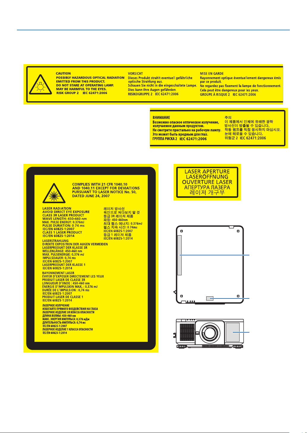
Laser Safety Caution
• ThisproductisclassiedasClass1ofIEC60825-1Thirdedition2014-05.
ThisproductisclassiedasClass3RofIEC60825-1Secondedition2007-03.
AlsocomplieswithFDAperformancestandards21CFR1040.10and1040.11forlaserproductsexceptfordevia-
tionspursuanttoLaserNoticeNo.50,datedJune24,2007.
Obeythelawsandregulationsofyourcountryinrelationtotheinstallationandmanagementofthedevice.
• Bluelaserdiodes:Wavelength450–460nm.
• Pulsewidth&repetitionrate:0.74ms,240Hz
• Outputpower:240W
• Thelasermoduleisequippedinthisproduct.
Useofcontrolsoradjustmentsofproceduresotherthanthosespeciedhereinmayresultinhazardousradiation
exposure.
CAUTION
• Useofcontrolsoradjustmentsorperformanceofproceduresotherthanthosespeciedhereinmayresultin
hazardousradiationexposure.
CAUTION – CLASS 3R LASER PRODUCT
LASERLIGHT–AVOIDDIRECTEYEEXPOSURE
vi
Important Information
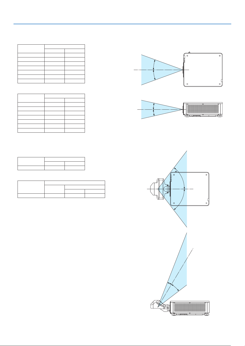
Applicablelensunit:NP16FL/NP17ZL/NP18ZL/NP19ZL/NP20ZL/NP21ZL/NP31ZL
HorizontalangleH
Lens Zoom
Tele Wide
NP16FL — 32.9
NP17ZL 15.5 21.7
NP18ZL 12.4 16.1
NP19ZL 7.7 12.7
NP20ZL 5.3 7.9
NP21ZL 3.4 5.4
NP31ZL 27.8 33.6
VerticalangleV
Lens Zoom
Tele Wide
NP16FL — 22.0
NP17ZL 9.8 14.0
NP18ZL 7.8 10.2
NP19ZL 4.8 8.0
NP20ZL 3.3 5.0
NP21ZL 2.1 3.4
NP31ZL 18.2 22.5
H
H
V
V
Applicablelensunit:NP39ML
HorizontalangleH
Lens Zoom
Tele Wide
NP39ML — 52.8
VerticalangleV
Lens Zoom
Tele Wide
V1 V2
NP39ML — 9.68 21.52
H
H
V
1
V
2
vii
Important Information
• ThecautionlabelandtheexplanatorylabelsoftheCLASS3RLASERPRODUCTSarestuckonthebelowindicated
positions.
Label1
Label2 Label3
Label 3
Label 1
Label 2
viii
Important Information
• Manufacturer'sIDLabel
(ForPX803UL-WH)
(ForPX803UL-BK)
PositionoftheManufacturer'sIDLabel

ix
Important Information
About Copyright of original projected pictures:
Pleasenotethatusingthisprojectorforthepurposeofcommercialgainortheattractionofpublicattentioninavenue
suchasacoffeeshoporhotelandemployingcompressionorexpansionofthescreenimagewiththefollowingfunc-
tionsmayraiseconcernabouttheinfringementofcopyrightswhichareprotectedbycopyrightlaw.
[ASPECTRATIO],[KEYSTONE],Magnifyingfeatureandothersimilarfeatures.
Turkish RoHS information relevant for Turkish market
EEE Yönetmeliğine Uygundur.
Thisdeviceisnotintendedforuseinthedirecteldofviewatvisualdisplayworkplaces.Toavoidincommodingreec-
tionsatvisualdisplayworkplacesthisdevicemustnotbeplacedinthedirecteldofview.

x
Important Information
Health precautions to users viewing 3D images
Beforeviewing,besuretoreadhealthcareprecautionsthatmaybefoundintheuser’smanualincludedwithyour3D
eyeglassesoryour3DcompatiblecontentsuchasBlu-rayDiscs,videogames,computer’svideolesandthelike.
Toavoidanyadversesymptoms,heedthefollowing:
• Donotuse3Deyeglassesforviewinganymaterialotherthan3Dimages.
• Allowadistanceof2m/7feetorgreaterbetweenthescreenandauser.Viewing3Dimagesfromtooclosea
distancecanstrainyoureyes.
• Avoidviewing3Dimagesforaprolongedperiodoftime.Takeabreakof15minutesorlongeraftereveryhour
ofviewing.
• Ifyouoranymemberofyourfamilyhasahistoryoflight-sensitiveseizures,consultadoctorbeforeviewing3D
images.
• Whileviewing3Dimages,ifyougetsicksuchasnausea,dizziness,queasiness,headache,eyestrain,blurry
vision,convulsions,andnumbness,stopviewingthem.Ifsymptomsstillpersist,consultadoctor.
• View3Dimagesfromthefrontofthescreen.Viewingfromananglemaycausefatigueoreyestrain.
Power management function
Inordertokeeppowerconsumptionlow,thefollowingpowermanagementfunctions(1)and(2)havebeensetwhen
shippedfromthefactory.Pleasedisplaytheon-screenmenuandchangethesettings(1)and(2)accordingtothe
aimofusingtheprojector.
1. STANDBY MODE (Factory preset: NORMAL)
• When[NORMAL]isselectedfor[STANDBYMODE],thefollowingterminalsandfunctionswillnotwork:
HDMIOUTterminal,Ethernet/HDBaseTPort,USBPort,LANfunctions,MailAlertfunction
(→page134)
2. AUTO POWER OFF (Factory preset: 1 hour)
• When[1:00]isselectedfor[AUTOPOWEROFF],youcanenabletheprojectortoautomaticallyturnoffin1
hourifthereisnosignalreceivedbyanyinputorifnooperationisperformed.
(→page135)
xi
Important Information
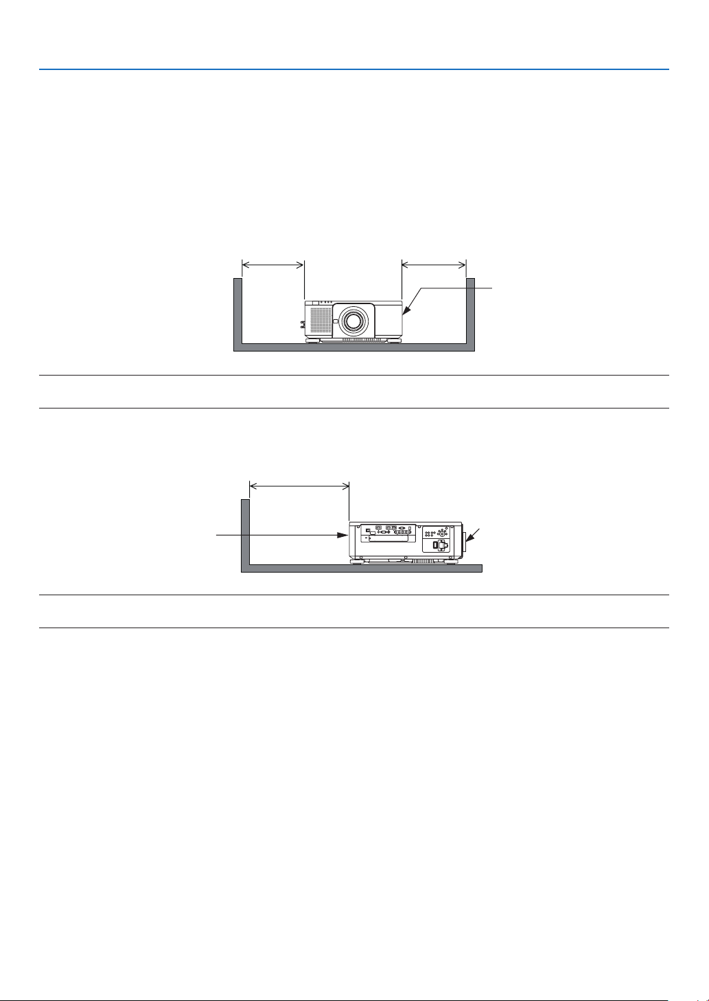
Clearance for Installing the Projector
Allowampleclearancebetweentheprojectoranditssurroundingsasshownbelow.
Thehightemperatureexhaustcomingoutofthedevicemaybesuckedintothedeviceagain.
AvoidinstallingtheprojectorinaplacewhereairmovementfromtheHVACisdirectedattheprojector.
HeatedairfromtheHVACcanbetakeninbytheprojector’sintakevent.Ifthishappens,thetemperatureinsidethe
projectorwillrisetoohighcausingtheover-temperatureprotectortoautomaticallyturnofftheprojectorspower.
• Concerningtotheportraitprojection,pleaserefer“Portraitprojection”onpage154.
Example 1 – If there are walls on both sides of the projector.
30cm/11.8"orgreater 30cm/11.8"orgreater
Intakevent
NOTE:
The drawing shows the proper clearance required for the front, back and top of the projector.
Example 2 – If there is a wall behind the projector.
50cm/19.7"orgreater
Lens
Exhaustvent
NOTE:
The drawing shows the proper clearance required for the right, left, and top of the projector.

xii
Table of Contents
Important Information ............................................................................................ i
1. Introduction ...........................................................................................................1
❶What’sintheBox? ..........................................................................................................1
❷IntroductiontotheProjector ...........................................................................................3
CongratulationsonYourPurchaseoftheProjector ..................................................3
General .....................................................................................................................3
Lightsource·Brightness ..........................................................................................3
Installation ................................................................................................................. 3
Videos .......................................................................................................................4
Network ..................................................................................................................... 4
Energy-saving ...........................................................................................................4
Aboutthisuser’smanual ........................................................................................... 5
❸PartNamesoftheProjector ...........................................................................................6
Front/Top ...................................................................................................................6
Rear ..........................................................................................................................7
Controls/IndicatorPanel ............................................................................................8
TerminalsFeatures ...................................................................................................9
❹PartNamesoftheRemoteControl ..............................................................................10
BatteryInstallation ..................................................................................................11
RemoteControlPrecautions ................................................................................... 11
OperatingRangeforWirelessRemoteControl ....................................................... 12
UsingtheRemoteControlinWiredOperation ........................................................ 12
2. Projecting an Image (Basic Operation) ...............................................13
❶FlowofProjectinganImage .........................................................................................13
❷ConnectingYourComputer/ConnectingthePowerCord ..............................................14
UsingtheSuppliedPowerCords ............................................................................15
UsingthePowerCordStopper ...............................................................................16
❸TurningontheProjector ...............................................................................................17
PerformingLensCalibration ...................................................................................18
NoteonStartupscreen(MenuLanguageSelectscreen) .......................................19
❹SelectingaSource .......................................................................................................20
Selectingthecomputerorvideosource..................................................................20
❺AdjustingthePictureSizeandPosition ........................................................................22
Adjustingtheverticalpositionofaprojectedimage(Lensshift) .............................23
Focus ......................................................................................................................26
Zoom
....................................................................................................................... 31
AdjustingtheTiltFoot .............................................................................................32
❻OptimizingComputerSignalAutomatically ..................................................................33
AdjustingtheImageUsingAutoAdjust ...................................................................33
❼TurningofftheProjector ...............................................................................................34
❽AfterUse.......................................................................................................................35
3. Convenient Features ......................................................................................36
❶Turnoffthelightoftheprojector(LENSSHUTTER) ....................................................36
❷TurningofftheImage .................................................................................................... 36
❸TurningOfftheOn-ScreenMenu(On-ScreenMute) ....................................................36

xiii
Table of Contents
❹FreezingaPicture ........................................................................................................37
❺MagnifyingaPicture .....................................................................................................38
❻ChangingLIGHTMODE/CheckingEnergy-SavingEffectUsingLIGHTMODE
[LIGHTMODE]........................................................................................................39
CheckingEnergy-SavingEffect[CARBONMETER] ..............................................41
❼CorrectingHorizontalandVerticalKeystoneDistortion[CORNERSTONE] .................42
❽PreventingtheUnauthorizedUseoftheProjector[SECURITY] ..................................45
❾Projecting3Dvideos.....................................................................................................48
Proceduretowatch3Dvideosusingthisprojector .................................................48
Whenvideoscannotbeviewedin3D .....................................................................51
❿ControllingtheProjectorbyUsinganHTTPBrowser ..................................................52
⓫StoringChangesforLensShift,Zoom,andFocus[LENSMEMORY] .........................58
Tostoreyouradjustedvaluesin[REF.LENSMEMORY]: .......................................59
Tocallupyouradjustedvaluesfrom[REF.LENSMEMORY]: ................................61
4. Multi-Screen Projection ...............................................................................64
❶Thingsthatcanbedoneusingmulti-screenprojection ................................................64
Case1.Usingasingleprojectortoprojecttwotypesofvideos[PIP/PICTURE
BYPICTURE] .........................................................................................................64
Case2.Usingfourprojectors(resolution:WUXGA)toprojectvideoswitha
resolutionof2560×1600pixels[TILING]...............................................................65
Thingstonotewheninstallingprojectors ................................................................ 67
❷DisplayingTwoPicturesattheSameTime ...................................................................68
Projectingtwoscreens ............................................................................................ 69
Switchingthemaindisplaywiththesub-displayandviceversa .............................70
Restrictions .............................................................................................................71
❸DisplayingaPictureUsing[EDGEBLENDING] ...........................................................72
Settingtheoverlapofprojectionscreens ................................................................ 73
BlackLevelAdjustment ...........................................................................................76
5. Using On-Screen Menu .................................................................................78
❶UsingtheMenus ...........................................................................................................78
❷MenuElements .............................................................................................................79
❸ListofMenuItems ........................................................................................................80
❹MenuDescriptions&Functions[INPUT] ......................................................................86
HDMI ....................................................................................................................... 86
DisplayPort .............................................................................................................. 86
BNC ........................................................................................................................86
BNC(CV) .................................................................................................................86
BNC(Y/C) ................................................................................................................86
COMPUTER ...........................................................................................................86
HDBaseT ................................................................................................................86
SLOT .......................................................................................................................86
ENTRYLIST ...........................................................................................................86
TESTPATTERN ...................................................................................................... 86
❺MenuDescriptions&Functions[ADJUST] ................................................................... 90
[PICTURE] ..............................................................................................................90
[IMAGEOPTIONS] .................................................................................................94
[VIDEO] ................................................................................................................... 98

xiv
Table of Contents
[3DSETTINGS] ....................................................................................................100
UsingtheLensMemoryFunction[LENSMEMORY] ............................................101
❻MenuDescriptions&Functions[DISPLAY] ................................................................103
[PIP/PICTUREBYPICTURE] ............................................................................... 103
[GEOMETRICCORRECTION] .............................................................................105
[EDGEBLENDING] ..............................................................................................109
[MULTISCREEN]..................................................................................................110
❼MenuDescriptions&Functions[SETUP] ................................................................... 112
[MENU] .................................................................................................................112
[INSTALLATION(1)] ............................................................................................... 114
[INSTALLATION(2)] ............................................................................................... 117
[CONTROL] ..........................................................................................................119
[NETWORKSETTINGS] ....................................................................................... 127
[SOURCEOPTIONS] ...........................................................................................132
[POWEROPTIONS] .............................................................................................134
ReturningtoFactoryDefault[RESET] ..................................................................136
❽MenuDescriptions&Functions[INFO.] .....................................................................137
[USAGETIME] ......................................................................................................137
[SOURCE(1)] ........................................................................................................137
[SOURCE(2)] ........................................................................................................138
[SOURCE(3)] ........................................................................................................138
[SOURCE(4)] ........................................................................................................138
[WIREDLAN] ........................................................................................................139
[VERSION(1)] .......................................................................................................139
[OTHERS] .............................................................................................................139
[HDBaseT] ............................................................................................................140
6. Connecting to Other Equipment ...........................................................141
❶Mountingalens(soldseparately) ...............................................................................141
Mountingthelens..................................................................................................141
Removingthelens ................................................................................................142
❷MakingConnections ...................................................................................................143
AnalogRGBsignalconnection .............................................................................143
DigitalRGBsignalconnection ..............................................................................144
ConnectinganExternalMonitor ...........................................................................147
ConnectingYourBlu-rayPlayerorOtherAVEquipment ....................................... 148
ConnectingComponentInput ...............................................................................149
ConnectingHDMIInput.........................................................................................150
Connectingadocumentcamera ...........................................................................151
ConnectingtoaWiredLAN ..................................................................................152
ConnectingtoaHDBaseTtransmissiondevice(soldcommercially) .................... 153
Portraitprojection(verticalorientation) .................................................................154
Stackingprojectors ...............................................................................................156
7. Maintenance .....................................................................................................159
❶CleaningtheLens.......................................................................................................159
❷CleaningtheCabinet ..................................................................................................159
8. User Supportware ..........................................................................................160
❶OperatingEnvironmentforSoftwareIncludedonCD-ROM .......................................160

xv
Table of Contents
NamesandFeaturesofBundledSoftwarePrograms ...........................................160
Downloadservice .................................................................................................160
❷InstallingSoftwareProgram .......................................................................................161
InstallationforWindowssoftware .......................................................................... 161
❸OperatingtheProjectorViatheLAN(VirtualRemoteTool) ........................................164
ConnecttheprojectortoaLAN. ............................................................................ 165
❹ControllingtheProjectoroveraLAN(PCControlUtilityPro4/Pro5) ........................167
9. Appendix ..............................................................................................................171
❶Throwdistanceandscreensize .................................................................................171
Lenstypesandthrowdistance .............................................................................171
Tablesofscreensizesanddimensions ................................................................173
Lensshiftingrange ................................................................................................174
❷MountingtheOptionalBoard(soldseparately) ..........................................................175
❸CompatibleInputSignalList .......................................................................................177
❹Specications .............................................................................................................180
PowerCord ...........................................................................................................183
❺CabinetDimensions ...................................................................................................184
❻Pinassignmentsandsignalnamesofmainterminals ...............................................185
❼Troubleshooting ..........................................................................................................187
IndicatorMessages ............................................................................................... 187
CommonProblems&Solutions ............................................................................189
Ifthereisnopicture,orthepictureisnotdisplayedcorrectly. ............................... 191
❽PCControlCodesandCableConnection ..................................................................192
❾TroubleshootingCheckList ......................................................................................... 193
1
1. Introduction
❶ What’s in the Box?
Makesureyourboxcontainseverythinglisted.Ifanypiecesaremissing,contactyourdealer.
Pleasesavetheoriginalboxandpackingmaterialsifyoueverneedtoshipyourprojector.
Projector
Dustcapforlens
* Theprojectorisshippedwithout
alens.Forthetypesoflensand
throwdistances,seepage171.
Remotecontrol
(7N901041)
AAalkalinebatteries
(x2)
Lenstheftprevention
screw(79TM1071)
Thisscrewmakesitdif-
culttoremovethelens
mountedontheprojec-
tor.(→page142)
Powercord×3
(79TM1021) (79TQ1001forAC120V) (79TQ1011forAC200V)
ForEurope/Asia/SouthAmerica ForNorthAmerica
4Stackingholders(79TM1101)
Whenstackingprojectors(doublestacking),thetiltfootoftheupperprojectorwillbeplacedontothesestackingholders.(→
page157)
For North America only
Limitedwarranty
For customers in Europe:
YouwillndourcurrentvalidGuar-
anteePolicyonourWebSite:
www.nec-display-solutions.com
• ImportantInfomation
(7N8N6631)
• QuickSetupGuide(7N8N6641)
• SecuritySticker
(Usethisstickerwhensecurity
passwordisseton.)
NECProjectorCD-ROM
User’smanual(PDF)andthe
utilitysoftware
(7N952341)
2
1. Introduction
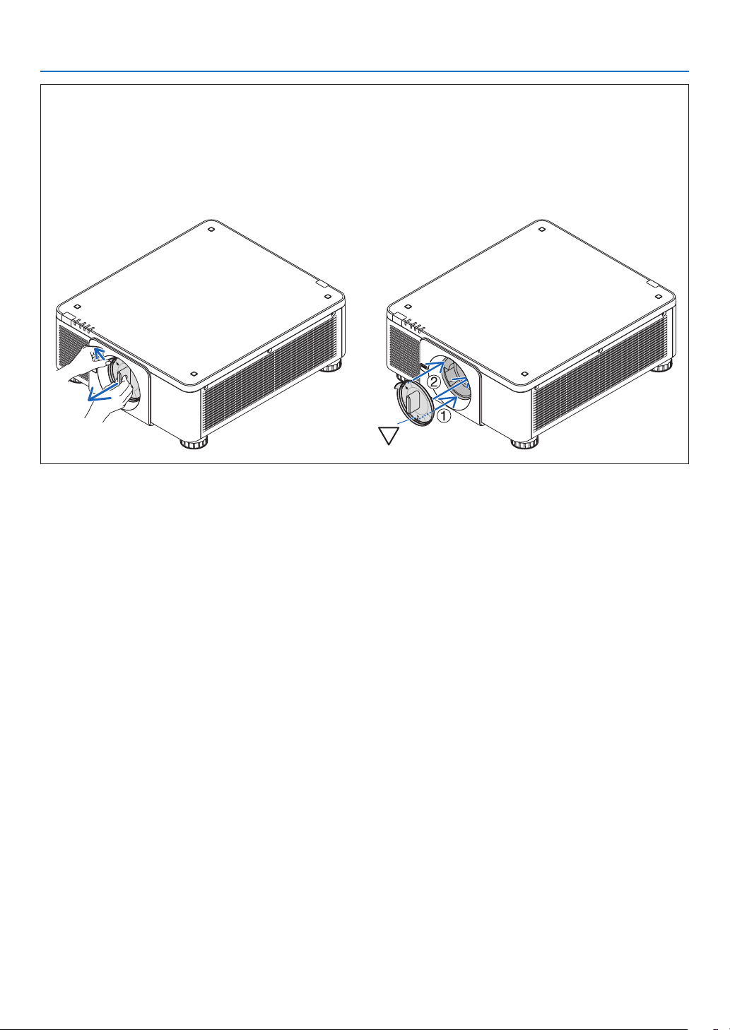
Attaching/Removing the Dust Cap
To remove the dust cap from theprojector, push the
tongueatthetopleftoutwardandpulltheknobatthe
centerofthecap.
Toattachthedustcaptotheprojector,locatethecatchon
thelowerendofthedustcapandplaceitintotheopen-
ingoftheprojectorwiththepointofatrianglemark(▽)
facingdownward(①inthegurebelow),andthenpush
theupperendofthedust cap against the projectorto
placethecatchesintotheslotwhileclutchingthehandle
(②inthegurebelow).

3
1. Introduction
❷ Introduction to the Projector
Thissectionintroducesyoutoyournewprojectoranddescribesthefeaturesandcontrols.
Congratulations on Your Purchase of the Projector
Thisprojectorisoneoftheverybestprojectorsavailabletoday.Theprojectorenablesyoutoprojectpreciseimages
upto500inchesacross(measureddiagonally)fromyourPCorMaccomputer(desktopornotebook),VCR,Blu-ray
player,ordocumentcamera.
Youcanusetheprojectoronatabletoporcart,youcanusetheprojectortoprojectimagesfrombehindthescreen,
andtheprojectorcanbepermanentlymountedonaceiling*
1
.Theremotecontrolcanbeusedwirelessly.
*
1
Donotattempttomounttheprojectoronaceilingyourself.
Theprojectormustbeinstalledbyqualiedtechniciansinordertoensureproperoperationandreducetherisk
ofbodilyinjury.
Inaddition,theceilingmustbestrongenoughtosupporttheprojectorandtheinstallationmustbeinaccordance
withanylocalbuildingcodes.Pleaseconsultyourdealerformoreinformation.
General
• Single-chipDLPprojectorwithhighresolutionandhighbrightness
Realizedtoprojecttheimageintheresolution1920×1200pixels(WUXGA),theaspectratioin16:10,andthe
brightnessin8000lumens.
Light source · Brightness
• Along-lifelaserdiodeisequippedinthelightmodule
Theproductcanbeoperatedatlowcostbecausethelaserlightsourcecanbeusedforalongtimewithoutrequir-
ingreplacementormaintenance.
• Brightnesscanbeadjustedwithinawiderange
Unlikewithordinarylightsources,thebrightnesscanbeadjustedfrom20to100%in1%increments.
• [CONSTANTBRIGHTNESS]mode
Brightnessnormallydecreaseswithuse,butbyselecting[CONSTANTBRIGHTNESS]mode,sensorsinsidethe
projectordetectandautomaticallyadjusttheoutput,therebymaintainingconstantbrightnessthroughoutthelife
ofthelightmodule.
However,ifbrightnessoutputissetatthemaximum,brightnesswilldecreasewithuse.
Installation
• Widerangeofoptionallensesselectableaccordingtotheplaceofinstallation
Thisprojectorsupports8typesofoptionallenses,providingaselectionoflensesadaptedtoavarietyofplaces
ofinstallationandprojectionmethods.
Inaddition,thelensescanbemountedandremovedinonetouch.
Notethatnolensismounteduponshipmentfromthefactory.Pleasepurchaseoptionallensesseparately.
• Thisprojectorcanbeinstalledanyanglewithinverticalandhorizontal360°range,however,lifeofoptical
parts will be shorten in the following installation state:
• Whentheprojectorisinstalledonwhichlensfacesdownward.
• Whentheintakeventontheprojectorsidefacesdownwardintheportraitinstallation.(Seepage154)
• Doublestackableforhighlightoutputprojection
Bystacking2projectors,increasedbrightnessonalargescreenispossible.
• Powerlenscontrolforquickandeasyadjustment
Byusingbuttonsontheprojectorortheremotecontrol,zoom,focus,andposition(lensshift)canbeadjusted.

4
1. Introduction
Videos
• Widerangeofinput/outputterminals(HDMI,DisplayPort,BNC,HDBaseT,etc.)andbuilt-inmonauralspeaker
Theprojectorisequippedwithavarietyofinput/outputterminals:HDMI,DisplayPort,BNC(5-core),computer
(analog),HDBaseT,etc.
Theprojector’sHDMIinput/outputterminalsandDisplayPortinputterminalsupportHDCP.
HDBaseT,promotedandadvancedbytheHDBaseTAlliance,isaconsumerelectronic(CE)andcommercialcon-
nectivitytechnology.
• Slotforoptionalboard
Thisprojectorhasaslotforoptionalboards(soldseparately).
• Simultaneousdisplayof2images(PIP/PICTUREBYPICTURE)
Twoimagescanbeprojectedsimultaneouslywithasingleprojector.
Therearetwotypesoflayoutsforthetwoimages:“picture-in-picture”(PIP)inwhichasub-pictureisdisplayed
onthemainpicture,and“picture-by-picture”(PICTUREBYPICTURE)inwhichthemainandsubpicturesare
displayednexttoeachother.
• Multi-screenprojectionusingmultipleprojectors
ThisprojectorisequippedwithmultipleHDMIinput&outputterminalsthatcanconnectmultipleprojectorsina
daisychain.Bydividingandprojectinghighresolutionimageoneachprojector,highqualityimagecanberealized.
Furthermore,theboundariesofthescreensaresmoothedusinganedgeblendingfunction.
• SupportsHDMI3Dformat
Thisprojectorcanbeusedtowatchvideosin3Dusingcommercially-availableactiveshutter-type3Deyewear
and3DemittersthatsupportXpand3D.
Network
• Convenientutilitysoftware(UserSupportware)providedasstandard
ThethreeutilitysoftwarestoredintheenclosedNECProjectorCD-ROM(VirtualRemoteTool,PCControlUtility
Pro4(forWindows)andPCControlUtilityPro5(forMacOS))canbeused.
• CRESTRONROOMVIEWcompatible
ThisprojectorsupportsCRESTRONROOMVIEW,allowingmultipledevicesconnectedtothenetworktobeman-
agedfromacomputerorcontroller.
Energy-saving
• Energy-savingdesignwithastandbypowerconsumptionof0.27wattsorunder
Whentheon-screenmenu’sstandbymodeissetto“NORMAL”,thepowerconsumptioninthestandbymodeis
0.27wattsorunder.
0.18wattswithpowervoltageAC100V-130Vand0.27wattswithpowervoltageAC200V-240V.
• “LIGHTMODE”forlowpowerconsumptionand“CarbonMeter”display
Theprojectorisequippedwithan“LIGHTMODE”forreducingpowerconsumptionduringuse.Furthermore,the
power-savingeffectwhentheLIGHTMODEissetisconvertedintotheamountofreductionsofCO
2
emissions
andthisisindicatedontheconrmationmessagedisplayedwhenthepoweristurnedoffandat“Information”on
theon-screenmenu(CARBONMETER).

5
1. Introduction
About this user’s manual
Thefastestwaytogetstartedistotakeyourtimeanddoeverythingrightthersttime.Takeafewminutesnowto
reviewtheuser’smanual.Thismaysaveyoutimelateron.Atthebeginningofeachsectionofthemanualyou’llnd
anoverview.Ifthesectiondoesn’tapply,youcanskipit.
6
1. Introduction
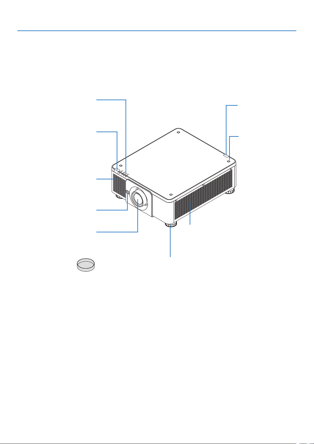
❸ Part Names of the Projector
Front/Top
Thelensissoldseparately.ThedescriptionbelowisforwhentheNP18ZLlensismounted.
Lens
RemoteSensor(locatedonthe
frontandtherear)
(→page12)
IndicatorPanel
(→page8)
Intakevent
Takesinairtocooltheunit.
(→pagexi,154)
RemoteSensor
(→page12)
StackingHolderxing
section
(4locations)
Intakevent
Takesinairtocooltheunit.
(→pagexi,154)
TiltFoot
(→page32)
LensRelease(LENS)Button
(→page142)
LensCap
(Thelenscapisattached
tothelens.)
7
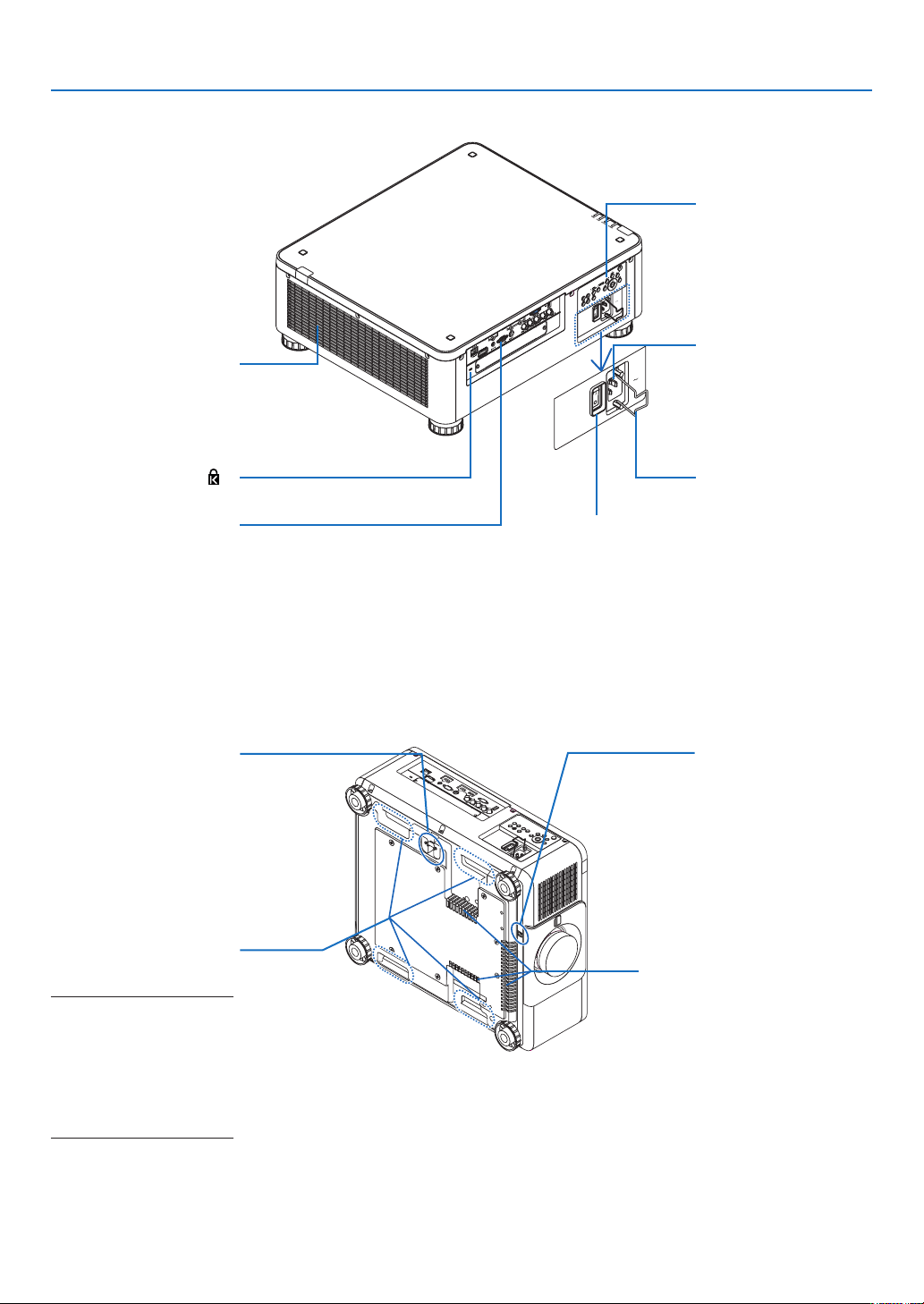
1. Introduction
Rear
ACINterminal
Connectthesupplied
powercord’sthree-pin
plughere,andplugthe
otherendintoanactive
walloutlet.(→page14)
Theftpreventionscrew
holeforthelensunit
Mainpowerswitch
WhileACpowerisbeingsupplied,setthe
mainpowerswitchtoONposition(|),then
yourprojectorwillenterastandbystate.
PowerCordStopper
(→page16)
* ThissecurityslotsupportstheMicroSaver
®
SecuritySystem.
Built-inSecuritySlot( )*
SecurityBar
Fixingatheftprevention
device.
Thesecuritybaraccepts
securitywiresorchains
upto0.18inch/4.6mmin
diameter.
Handle(locatedon4posi-
tions)
Fortransportation
NOTE:
• For moving the projector,
makesureyouhaveatleast
twopeople.Attemptingto
move the projector alone
could result in back pain
or other injuries.
Intakevent
Takesinairtocooltheunit.
(→pagexi,154)
Terminals
(→
page9)
Exhaustvent
Heatedaiirisexhausted
fromhere.
(→pagexi,154)
Controls
(→
page8)
8
1. Introduction
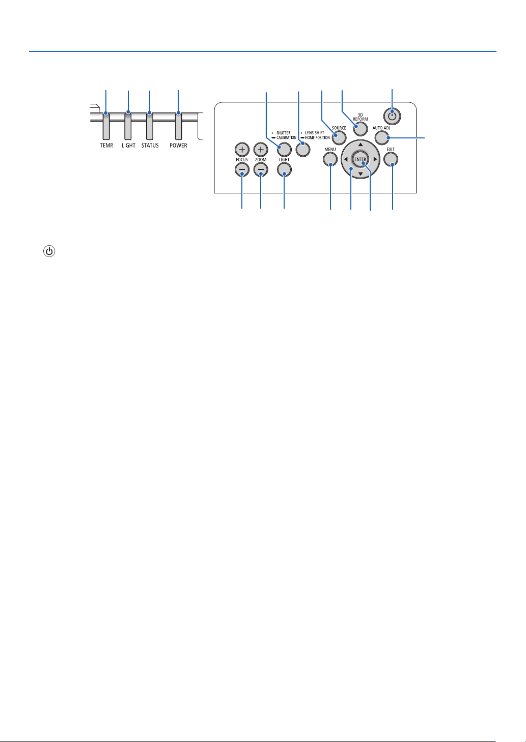
Controls/Indicator Panel
10 11
5
4
3
2
161513 8
7
141716 9 12
1. (POWER)Button
(→page17,34)
2. POWER Indicator
(→page17,18,34,186)
3. STATUS Indicator
(→page186)
4. LIGHT Indicator
(→page39,187)
5. TEMP.Indicator
(→page187)
6. SOURCEButton
(→page20)
7. AUTOADJ.Button
(→page33)
8. 3DREFORMButton
(→page42)
9. MENUButton
(→page78)
10. ▲▼◀▶Buttons
(→page78)
11.ENTERButton
(→page78)
12.EXITButton
(→page78)
13.SHUTTER/CALIBRATIONButton
(→page36)
14.LIGHTButton
(→page39)
15.LENSSHIFT/HOMEPOSITIONButton
(→page23,58,174)
16.FOCUS+/−Button
(→page26)
17.ZOOM+/−Button
(→page31)
9
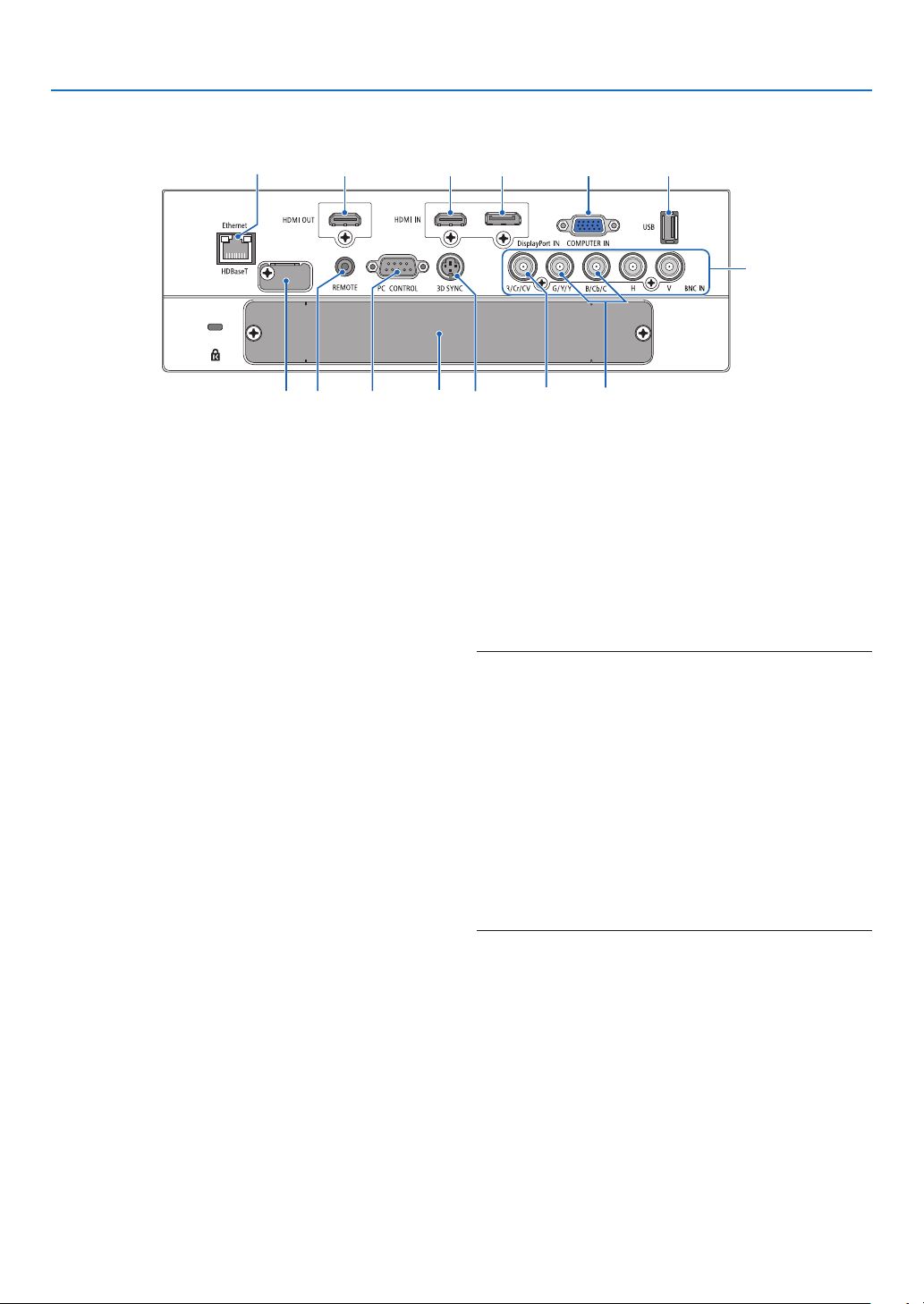
1. Introduction
Terminals Features
9
101112
1 7
4
56
238
1314
1. COMPUTERIN(MiniD-Sub15Pin)
(→page14,143,149,184)
2. DisplayPortINTerminal(DisplayPort20Pin)
(→page144,184)
3. HDMIINTerminal(TypeA)
(→page144,146,150,184)
4. BNCInput[R/Cr/CV,G/Y/Y,B/Cb/C,H,V]Termi-
nals(BNC×5)
(→page143,148)
5. BNC(Y/C)InputTerminal(BNC×2)
(→page148)
6. BNC(CV)InputTerminal(BNC×1)
(→page148)
7. USBPort(TypeA)
(→page185)
(Forfutureexpansion.Thisportallowsforpowersup-
ply.)
8. HDMIOUTTerminal(TypeA)
(→page147)
9. Ethernet/HDBaseTPort(RJ-45)
(→page152,153,185)
10.3DSYNCTerminal(MiniDIN3Pin)
(→page50)
11.PCCONTROLPort(D-Sub9Pin)
(→page185,191)
Use this port to connect a PCor control system.
Thisenablesyoutocontroltheprojectorusingserial
communicationprotocol.Ifyouarewritingyourown
program,typicalPCcontrolcodesareonpage191.
12.REMOTETerminal(StereoMini)
Usethisjackforwiredremotecontroloftheprojector
usingacommerciallyavailableremotecablewith⌀3.5
stereomini-plug(withoutresistance).
Connecttheprojectorandthesuppliedremotecontrol
usingacommerciallyavailablewiredremotecontrol
cable.
(→
page12)
NOTE:
• WhenaremotecontrolcableisconnectedtotheREMOTE
terminal,infraredremotecontroloperationscannotbeper-
formed.
• PowercannotbesuppliedfromtheREMOTEterminaltothe
remotecontrol.
• When [HDBaseT] is selectedinthe[REMOTE SENSOR]
andtheprojectoris connectedtoacommercially-available
transmissiondevicethatsupportsHDBaseT,remotecontrol
operationsininfra-redcannotbecarriedoutiftransmission
ofremotecontrolsignalshasbeensetupinthetransmission
device.However,remotecontrolusinginfraredrayscanbe
carriedoutwhenthepowersupplyofthetransmissiondevice
is switched off.
13. SLOT
(→page175)
14. Service terminal
Forserviceonly
10
1. Introduction
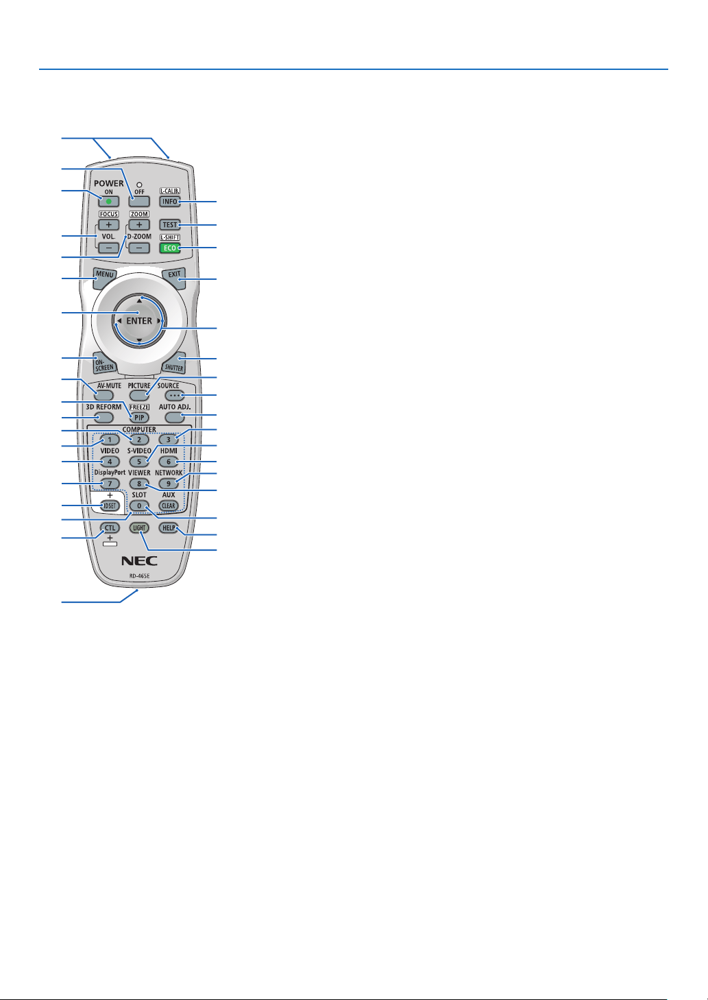
❹ Part Names of the Remote Control
1. Infrared Transmitter
(→page12)
2. RemoteJack
Connectacommerciallyavailable
remotecablehereforwiredopera-
tion.(→page12)
3. POWERONButton
(→page17)
4. POWEROFFButton
(→page34)
5. INFO/L-CALIB.Button
Displaythe[SOURCE(1)]screen
oftheon-screenmenu.
(→page18,137)
6. VOL./FOCUS+/−Buttons
(→page26)
7. D-ZOOM/ZOOM+/−Buttons
(→page38)
8. TESTButton
(→page86)
9. ECO/L-SHIFTButton
(→page25,39)
10.MENUButton
(→page78)
11.EXITButton
(→page78)
12.ENTERButton
(→page78)
13. ▲▼◀▶Button
(→page78)
14.ON-SCREENButton
(→page36)
15.SHUTTERButton
(→page36)
16.AV-MUTEButton
(→page36)
17.PICTUREButton
(→page90)
18.SOURCEButton
(→page20)
19.3DREFORMButton
(→page42)
20.PIP/FREEZEButton
(→page37,69)
1
3
4
6
14
10
12
16
20
7
2
5
8
9
11
15
18
17
13
21
19
25
28
32
23
22
35
24
30
26
29
34
27
31
36
33
21.AUTOADJ.Button
(→page33)
22,23.COMPUTER1/2Button
(→page20)
24.COMPUTER3Button
(This button is notwork on this
projector.)
25.VIDEOButton
(→page20)
26.S-VIDEOButton
(→page20)
27.HDMIButton
(→page20)
28.DisplayPortButton
(→page20)
29.VIEWERButton
(TheVIEWERbuttonwillnotwork
onthisseriesofprojectors.)
30.NETWORKButton
(→page20)
31.SLOTButton
(→page175)
32.IDSETButton
(→page125)
33.Numeric(0to9/CLEAR)But-
tons
(→
page125)
(TheAUXbuttonwillnotworkon
thisseriesofprojectors.)
34.CTLButton
Thisbuttonisusedinconjunction
with other buttons, similar toa
CTRLkeyonacomputer.
35.LIGHTButton
Thisbuttonisusedtoturnonthe
backlight forthe remote control
buttons.
Thebacklightwill turn off if no
buttonoperation is made for10
seconds.
36.HELPButton
(→page137)
11
1. Introduction
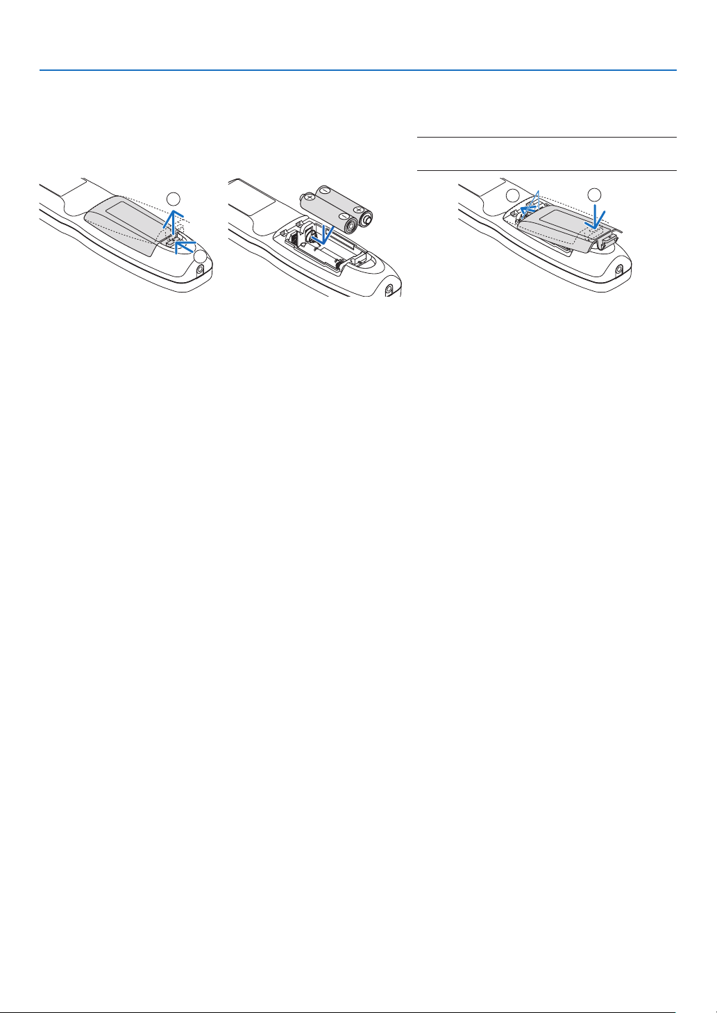
Battery Installation
1. Press the catch and remove
the battery cover.
2. Install new ones (AA). En-
sure that you have the bat-
teries’ polarity (+/−) aligned
correctly.
3. Slip the cover back over the batteries until
it snaps into place.
NOTE:Donotmixdifferenttypesofbatteriesornew
and old batteries.
1
2
1
2
Remote Control Precautions
• Handletheremotecontrolcarefully.
• Iftheremotecontrolgetswet,wipeitdryimmediately.
• Avoidexcessiveheatandhumidity.
• Donotshort,heat,ortakeapartbatteries.
• Donotthrowbatteriesintore.
• Ifyouwillnotbeusingtheremotecontrolforalongtime,removethebatteries.
• Ensurethatyouhavethebatteries’polarity(+/−)alignedcorrectly.
• Donotusenewandoldbatteriestogether,orusedifferenttypesofbatteriestogether.
• Disposeofusedbatteriesaccordingtoyourlocalregulations.
12
1. Introduction
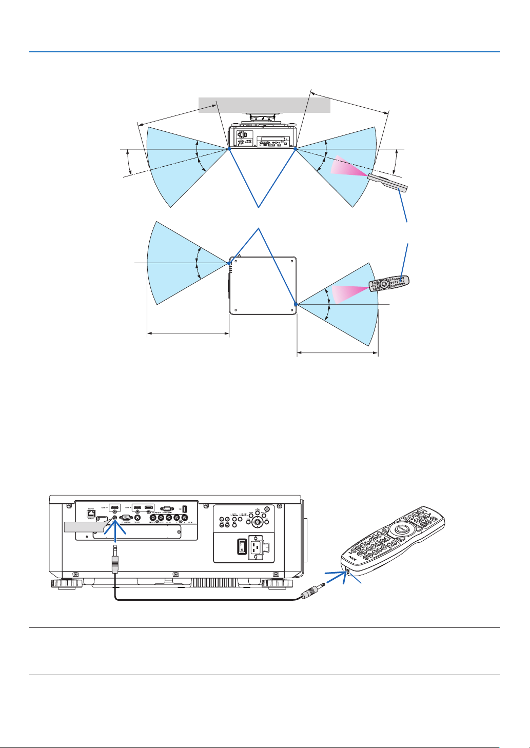
Operating Range for Wireless Remote Control
7
m/276
inch
7m/276inch
Remotecontrol
Remotesensoronprojectorcabinet
7
m/276
inch
7m/276inch
30°
30°
30°
30°
15°
30°
30°
30°
15°
30°
• Theinfraredsignaloperatesbyline-of-sightuptoadistanceofabovemetersandwithina60-degreeangleofthe
remotesensorontheprojectorcabinet.
• Theprojectorwillnotrespondifthereareobjectsbetweentheremotecontrolandthesensor,orifstronglightfalls
onthesensor.Weakbatterieswillalsopreventtheremotecontrolfromproperlyoperatingtheprojector.
Using the Remote Control in Wired Operation
ConnectoneendoftheremotecabletotheREMOTEterminalandtheotherendtotheremotejackontheremote
control.
REMOTE
RemoteJack
NOTE:
• WhenaremotecableisinsertedintotheREMOTEterminal,theremotecontroldoesnotworkforinfraredwirelesscommunication.
• PowerwillnotbesuppliedtotheremotecontrolbytheprojectorviatheREMOTEjack.Batteryisneededwhentheremotecontrol
is used in wired operation.

13
Thissectiondescribeshowtoturnontheprojectorandtoprojectapictureontothescreen.
❶ Flow of Projecting an Image
Step 1
• Connectingyourcomputer/Connectingthepowercord(→ page 14)
Step 2
• Turningontheprojector(→ page 17)
Step 3
• Selectingasource(→ page 20)
Step 4
• Adjustingthepicturesizeandposition(→ page 22)
• Correctingkeystonedistortion[CORNERSTONE](→ page 42)
Step 5
• Adjustingapicture
- Optimizingacomputersignalautomatically(→page33)
Step 6
• Makingapresentation
Step 7
• Turningofftheprojector(→ page 34)
Step 8
• Afteruse(→ page 35)
2. Projecting an Image (Basic Operation)
14
2. Projecting an Image (Basic Operation)
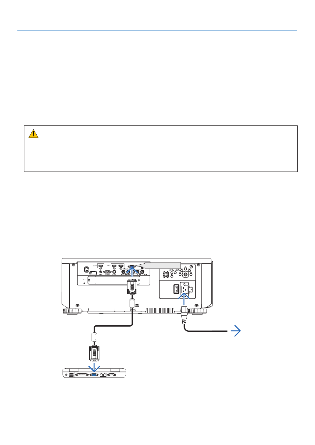
❷ Connecting Your Computer/Connecting the Power Cord
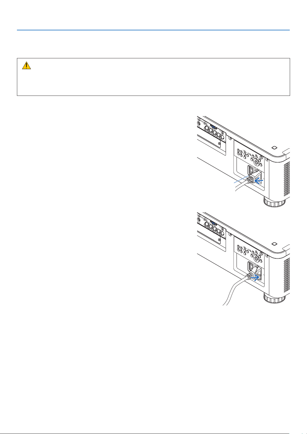
1. Connectyourcomputertotheprojector.
Thissectionwillshowyouabasicconnectiontoacomputer.Forinformationaboutotherconnections,see“(2)
MakingConnections”onpage143.
Connectthedisplayoutputterminal(miniD-sub15pin)onthecomputertotheCOMPUTERINterminalonthe
projectorwithacommercially-availablecomputercable(withferritecore)andthenturntheknobsoftheterminals
tosecurethem.
2. Connectthesuppliedpowercordtotheprojector.
WARNING
MAKESURETOTAKETHEGROUNDCONNECTIONFORTHEDEVICE.
TOPREVENTFIREORSHOCK,DONOTEXPOSETHISUNITTORAINORMOISTURE.
DO NOTUSETHIS UNIT'S PLUGWITH ANEXTENSION CORD OR INAN OUTLET UNLESS ALLTHE
PRONGSCANBEFULLYINSERTED.
ImportantInformation:
• Whenplugginginorunpluggingthesuppliedpowercord,makesurethatthemainpowerswitchispushedto
theoff[O]position.Failuretodosomaycausedamagetotheprojector.
• Donotuseathree-phasepowersupply.Doingsomaycauseofmalfunction.
Firstconnectthesuppliedpowercord’sthree-pinplugtotheACINterminaloftheprojector,andthenconnectthe
otherplugofthesuppliedpowercordinthewalloutlet.
COMPUTER IN
Makesurethattheprongsarefullyinsertedinto
boththeACINterminalandthewalloutlet.
Towalloutlet
Computercable(withferritecore)
(soldcommercially)

15
2. Projecting an Image (Basic Operation)
CAUTION:
PartsoftheprojectormaybecometemporarilyheatediftheprojectoristurnedoffwiththePOWERbuttonorifthe
ACpowersupplyisdisconnectedduringnormalprojectoroperation.
Usecautionwhenpickinguptheprojector.
Using the Supplied Power Cords
Selectthepowercordsuitableforyourcountryorregion.
ForEurope/Asia/SouthAmerica ForNorthAmerica
(120V) (200V)
(→page183)
16
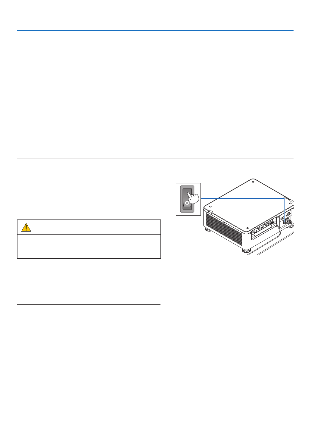
2. Projecting an Image (Basic Operation)
Using the Power Cord Stopper
TopreventthepowercordfromaccidentlyremovingfromtheACINoftheprojector,attachthepowercordstopper
toclampthepowercord.
CAUTION
• Topreventthepowercordfromcomingloose,makesurethatalltheprongsofthepowercordarefullyinserted
intotheACINterminaloftheprojectorbeforeusingthepowercordstoppertoxthepowercord.Aloose
contactofthepowercordmaycauseareorelectricshock.
Attaching the power cord stopper
1. Raise up the power cord stopper and lay it over the power cord.
Powercord
stopper
• Forreleasingthestopper,raiseupthestopperandlayitdownto
theoppositeside.
17
2. Projecting an Image (Basic Operation)
❸ Turning on the Projector
NOTE:
• Theprojectorhastwopowerswitches:AmainpowerswitchandaPOWERbutton(POWERONandOFFontheremotecontrol)
•Turningontheprojector:
1. Press the main power switch to the ON position (I).
Theprojectorwillgointostandbymode.
2. Press the POWER button .
Theprojectorwillbecomereadytouse.
•Turningofftheprojector:
1. Press the POWER button.
Theconrmationmessagewillbedisplayed.
2. Press the POWER button again.
Theprojectorwillgointostandbymode.
3. Press the main power switch to the OFF position (O).
Theprojectorwillbeturnedoff.
Preparation: Remove the lens cap from the lens unit.
1. Press the main power switch to the ON position ( I ).
ThePOWERindicatorlightsupred.*
* ThisindicatesthattheSTANDBYmodeisin[NORMAL]
setting.
(→page134,186)
WARNING
The projector produces a stronglight.When turning on
thepower,makesurenoonewithinprojectionrangeis
lookingatthelens.
NOTE:
• The[STANDBYMODE]settingwillbedisabledandtheprojector
willgointothesleepmodewhenthenetworkserviceisutilizedor
theprojectorreceivesHDBaseTsignal.Inthesleepmode,thefans
in the projector rotate for the purpose of interior parts protection.
Pleaserefertopage134aboutthesleepmode.
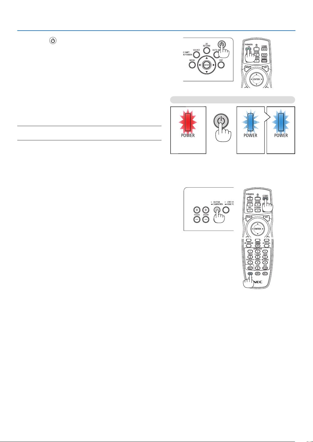
18
2. Projecting an Image (Basic Operation)
2. Press the (POWER) button on the projector cabinet
or the POWER ON button on the remote control.
ThePOWER indicator goes from a steady red light to
aashingblue light,andthepicture isprojectedonthe
screen.
TIP:
• Whenthemessage“PROJECTORISLOCKED!ENTERYOUR
PASSWORD.” is displayed, it meansthatthe[SECURITY]
featureisturnedon.(→ page 45)
Afteryouturnonyourprojector,ensurethatthecomputer
orvideosourceisturnedon.
NOTE:Thebluescreen([BLUE]background)isdisplayedwhenno
signalisbeinginput(byfactorydefaultmenusettings).
Standby Blinking Power On
Steady red light
Blinking blue
light
Steady blue
light
(→page186)
Performing Lens Calibration
Afterinstallationorreplacementofthelens,besuretoperform
[LENSCALIBRATION]bypressingandholdingtheSHUTTER/
CALIBRATION buttonon the projector cabinet for at least
twosecondsorbyholdingtheCTLbuttonandpressingthe
INFO/L-CALIB.buttonontheremotecontrol.Calibrationcor-
rectstheadjustablezoom,shift,andfocusrange.Ifcalibration
isnotperformed,youmaynotbeabletogetthebestfocus
andzoomevenifyouadjustthefocusandzoomforthelens.
• Thefollowinglensesneedcalibration:
NP16FL,NP17ZL,NP18ZL,NP19ZL,NP20ZL,NP21ZL,
NP31ZL
19
2. Projecting an Image (Basic Operation)
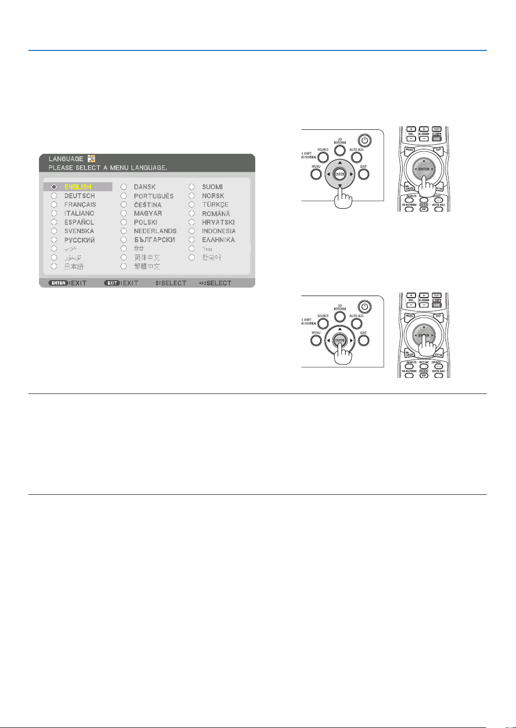
Note on Startup screen (Menu Language Select screen)
Whenyourstturnontheprojector,youwillgettheStartupmenu.Thismenugivesyoutheopportunitytoselectone
ofthe29menulanguages.
To select a menu language, follow these steps:
1. Use the ▲, ▼, ◀ or ▶buttontoselectoneofthe29
languagesfromthemenu.
2. Press the ENTER button to execute the selection.
After this has been done, you can proceed to themenu
operation.
Ifyouwant,youcanselectthemenulanguagelater.
(→[LANGUAGE]onpage82and112)
NOTE:
• Ifoneofthefollowingthingshappens,theprojectorwillnotturnon.
- Iftheinternaltemperatureoftheprojectoristoohigh,theprojectordetectsabnormalhightemperature.Inthisconditionthe
projectorwillnotturnontoprotecttheinternalsystem.Ifthishappens,waitfortheprojector’sinternalcomponentstocool
down.
- IftheSTATUSindicatorlightsorangewiththepowerbuttonpressed,itmeansthatthe[CONTROLPANELLOCK]isturnedon.
Cancelthelockbyturningitoff.(→ page 124)
• WhilethePOWERindicatorisblinkingblueinshortcycles,thepowercannotbeturnedoffbyusingthepowerbutton.(Whilethe
POWERindicatorisblinkingblueinlongcycles,theOFFTIMERisfunctionedandthepowercanbeturnedoff.)
20
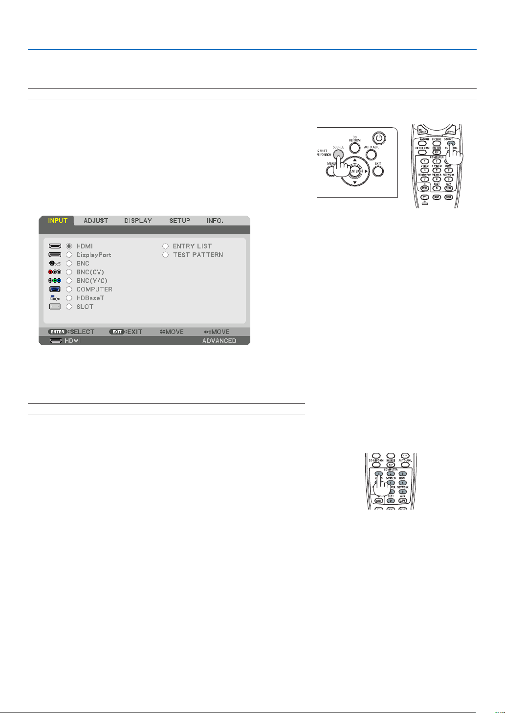
2. Projecting an Image (Basic Operation)
❹ Selecting a Source
Selecting the computer or video source
NOTE:Turnonthecomputerorvideosourceequipmentconnectedtotheprojector.
Detecting the Signal Automatically
Press the SOURCE button for 1 second or longer.Theprojector will
searchfortheavailableinputsourceanddisplayit.Theinputsourcewill
changeasfollows:
HDMI→DisplayPort→BNC→BNC(CV)→BNC(Y/C)→COMUPTER
→HDBaseT→SLOT→ …
• Pressitbrieytodisplaythe[INPUT]screen.
Pressthe▼/▲buttonstomatchthetargetinputterminalandthen
presstheENTERbuttontoswitchtheinput.Todeletethemenudisplay
inthe[INPUT]screen,presstheMENUorEXITbutton.
TIP:Ifnoinputsignalispresent,theinputwillbeskipped.
Using the Remote Control
Press any oneof the HDMI, DisplayPort, COMPUTER 2,VIDEO, S-
VIDEO,COMPUTER1,NETWORK,orSLOTbuttons.
• COMPUTER2buttonselectstheBNCinputterminal.
• VIDEObuttonselectstheBNC(CV)inputterminal(CompositeVideo).
• S-VIDEObuttonselectstheBNC(Y/C)inputterminal(S-Video).
21
2. Projecting an Image (Basic Operation)
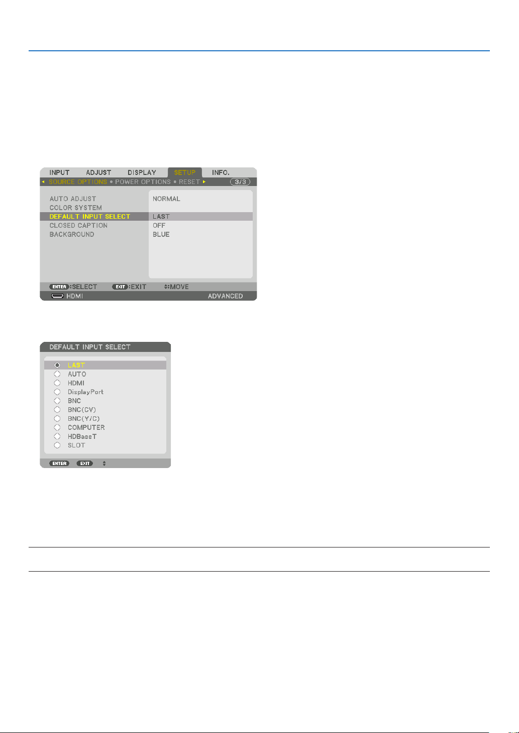
Selecting Default Source
Youcansetasourceasthedefaultsourcesothatitwillbedisplayedeachtimetheprojectoristurnedon.
1. Press the MENU button.
Themenuwillbedisplayed.
2. Press the ▶buttontoselect[SETUP]andpressthe▼buttonortheENTERbuttontoselect[BASIC].
3. Press the ▶buttontoselect[SOURCEOPTIONS].
4. Press the ▼buttonfourtimestoselect[DEFAULTINPUTSELECT]andpresstheENTERbutton.
The[DEFAULTINPUTSELECT]screenwillbedisplayed.
(→page132)
5. Selectasourceasthedefaultsource,andpresstheENTERbutton.
6. Press the EXIT button three times to close the menu.
7. Restart the projector.
Thesourceyouselectedinstep5willbeprojected.
NOTE:Evenwhen[AUTO]isturnedon,the[HDBaseT]willnotbeautomaticallyselected.Tosetyournetworkasthedefaultsource,
select[HDBaseT].
TIP:
• WhentheprojectorisinStandbymode,applyingacomputersignalfromacomputerconnectedtotheCOMPUTERINinputwill
powerontheprojectorandsimultaneouslyprojectthecomputer’simage.
([AUTOPOWERONSELECT]→ page 135)
• OntheWindows7keyboard,acombinationoftheWindowsandPkeysallowsyoutosetupexternaldisplayeasilyandquickly.
22
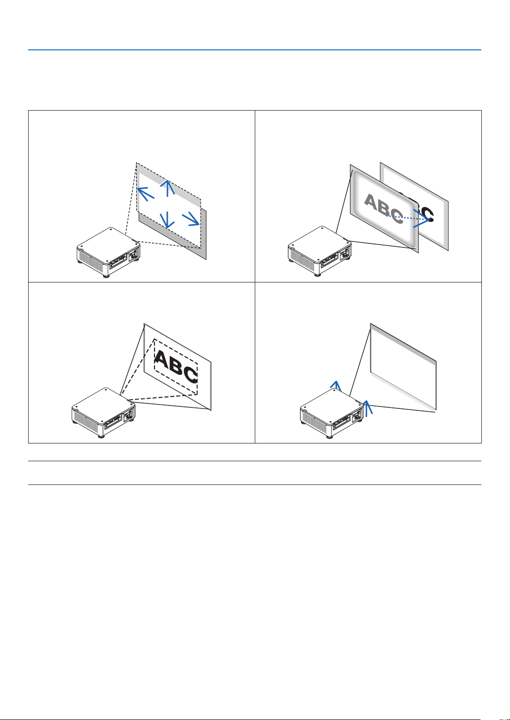
2. Projecting an Image (Basic Operation)
❺ Adjusting the Picture Size and Position
Usethelensshiftdial,theadjustabletiltfoot,thezoomringandthefocusringtoadjustthepicturesizeandposition.
Inthischapterdrawingsandcablesareomittedforclarity.
Adjustingtheprojectedimage’s vertical and horizontal
position
[Lensshift]
(→page23)
Adjustingthefocus
[Focus]
(→
page26)
Finelyadjustingthesizeofanimage
[Zoom]
(→page31)
Adjustingtheprojectedimage’sheightandhorizontaltilt
[Tiltfoot]*¹
(→page32)
NOTE*
1
:Adjusttheprojectedimage’sheightusingthetiltfootwhenyouwanttoprojecttheimageatapositionhigherthanthe
lensshiftadjustmentrange.
TIP:
• Built-intestpatternscanbeconvenientlyusedforadjustingthepicturesizeandposition.(→ page 86)
ApressoftheTESTbuttonwilldisplaythetestpattern.The◀ or ▶ button can select one test pattern. To close the test pattern,
change the source to another.
23
2. Projecting an Image (Basic Operation)
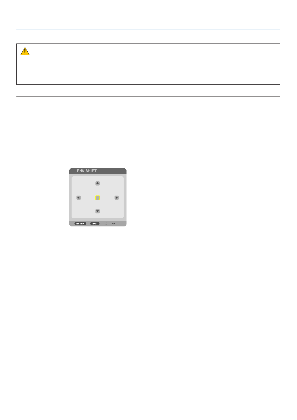
Adjusting the vertical position of a projected image (Lens shift)
CAUTION
• Performtheadjustmentfrombehindorfromthesideoftheprojector.Performingadjustmentfromthefrontcould
exposeyoureyestostronglightwhichcouldinjurethem.
• Keephandsawayfromthelensmountingportionwhileperformingalensshift.Failuretodosocouldresultin
ngersbeingpinchedbythemovinglens.
NOTE:
• ThelensshiftfunctionisnotavailableontheprojectorwitheitherNP16FLorNP39MLlensinstalled.
ForusingNP16FL,setbackthelenstothehomeposition.
ForusingNP39ML,select[SETUP]→[INSTALLATION(2)]→[LENSPOSITION]→[TYPE]ontheonscreenmenu,thelenswill
bemovedtotheappropriatepositionautomatically.
• Shiftingthelenstothemaximuminobliqueanglewillcausetheedgesoftheimagetobecomedarkorwillcausedarkshadows.
Adjusting with buttons on the cabinet
1. Press the LENS SHIFT/HOME POSITION button.
The[LENSSHIFT]screenwillbedisplayed.
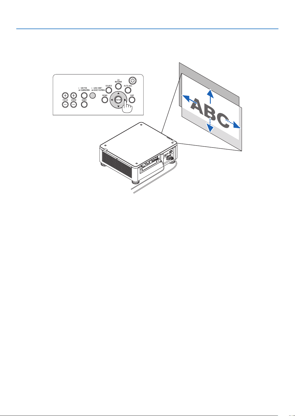
24
2. Projecting an Image (Basic Operation)
2. Press the ▼▲◀ or ▶ button.
Usethe▼▲◀▶buttonstomovetheprojectedimage.
• Returningthelensshiftpositiontothehomeposition
PressandholdtheLENSSHIFT/HOMEPOSITIONbuttonfor2secondstoreturnthelensshiftpositiontothe
homeposition(nearlycenterposition)
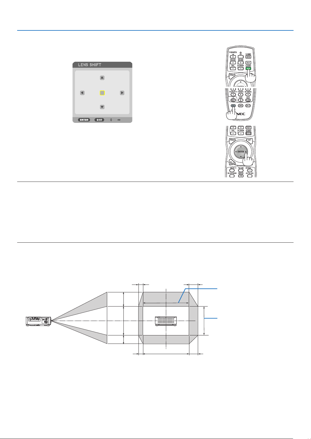
25
2. Projecting an Image (Basic Operation)
Adjusting with the remote control
1. HoldtheCTLbuttonandpresstheECO/L-SHIFTbutton.
The[LENSSHIFT]screenwillbedisplayed.
2. Press the ▼▲◀ or ▶ button.
Usethe▼▲◀▶buttonstomovetheprojectedimage.
NOTE:
LensCalibration
Ifthepoweroftheprojectoriswronglyshutdownduringthemotionoflensshift,itmayshiftthehomepositionofthelensand
maycauseofmalfunction.Inthiscase,performlenscalibration.
Lenscalibrationprocedures
1.Powerontheprojector.
2.Pressthe(SHUTTER/CALIBRATION)buttononthecontrolpanelover2secondsorkeeppressingtheCTLbuttonandpressthe
INFO/L-CALIB.buttonontheremotecontrol.
Calibrationisperformed.
TIP:
• Thediagrambelowshowsthelensshiftadjustmentrange(projectionmode:desktopfront).Toraisetheprojectionpositionhigher
thanthis,adjustbythetiltfoot.(→ page 32)
100%V
50%V
30%V
100%H
20%H
10%H
10%H
20%H
Heightofprojectedimage
Widthofprojectedimage
Descriptionofsymbols:Vindicatesvertical(heightoftheprojectedimage),Hindicateshorizontal(widthoftheprojectedimage).
26
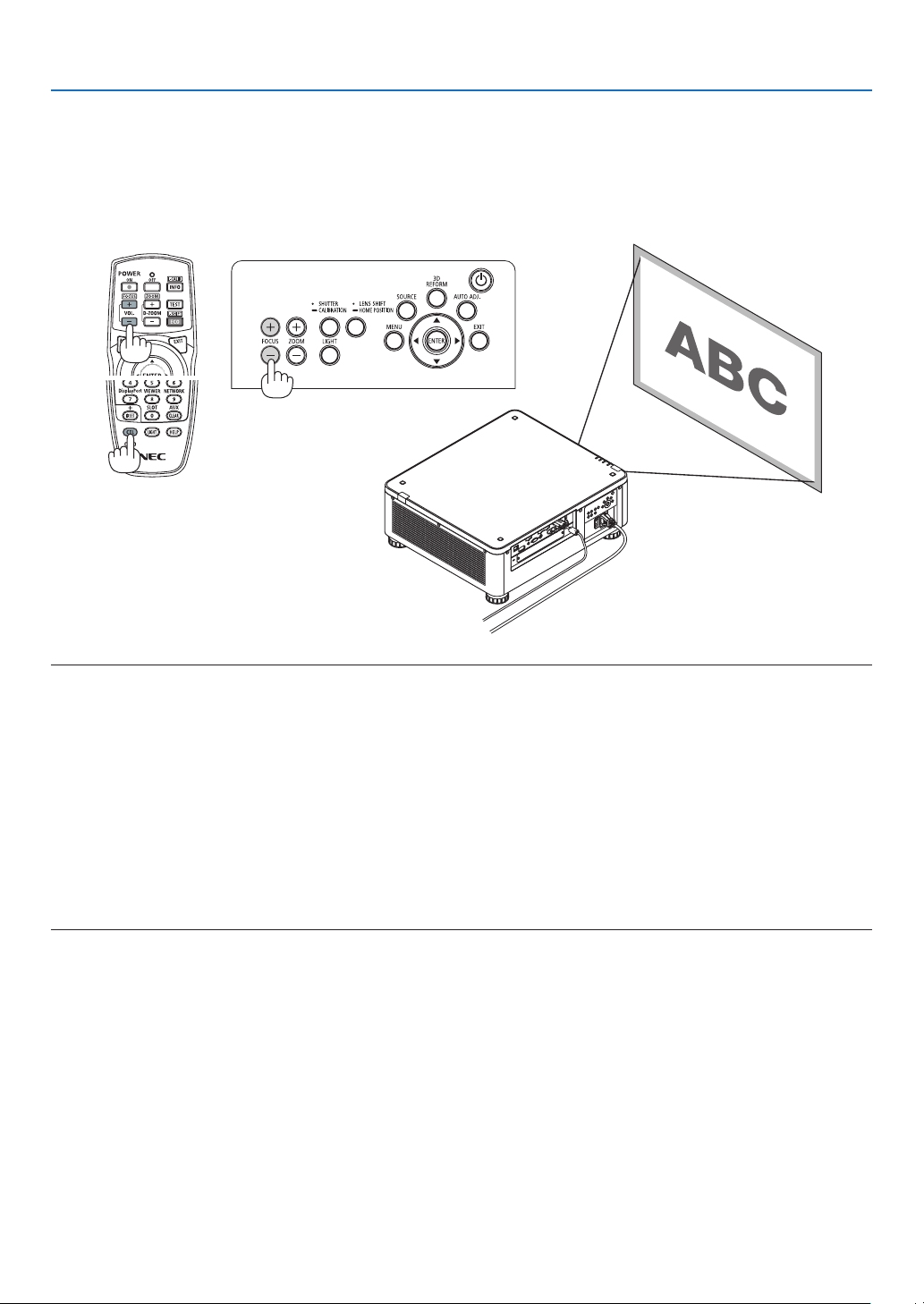
2. Projecting an Image (Basic Operation)
Focus
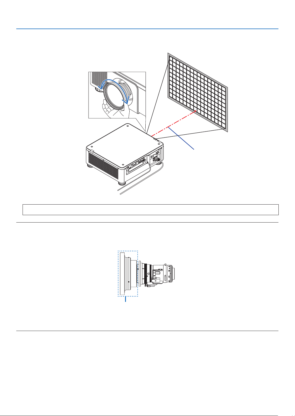
Applicablelensunit:NP16FL/NP17ZL/NP18ZL/NP19ZL/NP20ZL/NP21ZL
1. PresstheFOCUS+/−button.
• Ontheremotecontrol,whilepressingontheCTLbutton,pressonVOL/FOCUS(+)or(−)button.
Thefocusisadjusted.
TIP:
Toobtainthebestfocus,performthefollowing(forpermanentinstallation)
Preparation:Warmuptheprojectorforonehour.
1. UsetheFOCUS+/−buttonstomakesureyouobtainthebestfocus.Ifyoudonot,movetheprojectorback
andforth.
2. Selectthe[TESTPATTERN]fromthemenuanddisplaythetestpattern.(→ page 86)
• YoucanalsousetheTESTbuttonontheremotecontroltodisplaythetestpattern.
3. KeeppressingtheFOCUS−buttonuntilthegridofthetextpatternismadeinvisible.
4. KeeppressingtheFOCUS+buttonuntilyouobtainthebestfocus.
Ifyouadjustbeyondthebestfocalpoint,gobacktostep3andrepeattheprocedures.
27
2. Projecting an Image (Basic Operation)
Applicablelensunit:NP31ZL
1. Focusontheprojectedimagearoundtheopticalaxis.(Poweredfocus)
Thedrawingbelowshowsanexamplewhentheprojectedimageisshiftedupward.Inthiscasetheopticalaxisis
atthebottomedgeoftheprojectedimage.
Adjusting with buttons on the cabinet
PresstheFOCUS+/−BUTTONonthecontrolpanel
Adjusting with the remote control
PresstheVOL/FOCUSbuttonholdingtheCTLbutton
Opticalaxis
* Whenthelensisatthecenterposition,theopticalaxisisatthecenteroftheimage.Inthiscase,adjustthefocus
atthecenteroftheprojectedimage.
28
2. Projecting an Image (Basic Operation)
2. Adjustthefocusattheedgesoftheprojectedimage.(Manualfocus)
Turntheedgefocusringclockwiseorcounterclockwise.
Opticalaxis
Thiscompletesadjustingtheprojectedimage’soverallfocus.
NOTE:
TheNP31ZLsupportstheLensMemoryfunction,whichallowsyoutostoreadjustedvalueforLensShift,Zoom,andFocus.
IfyouaccidentallymovetheEdgefocusring(drawingshownbelow)afterhavingstoredadjustedvalues,theadjustedvaluesstored
intheLensMemorywillnotbecorrectlyapplied.
Edgefocusring
Afterhavingremovedthelensfromtheprojectorandmounteditback,calluptheadjustedvaluesstoredintheLensMemoryand
thenfollowStep2intheprocedureabovetoadjustthefocusattheedgesoftheprojectedimageagain.
29
2. Projecting an Image (Basic Operation)
TIP:Toobtainthebestfocus,performthefollowing(forpermanentinstallation)
Preparation:Warmuptheprojectorforonehour.
1.PresstheFOCUS+/−buttonstochecktheadjustablefocusrange.Forcheckingitbytheremotecontrol,pressandholdtheCTL
buttonandpressVOL./FOCUS+/−button.Iftheprojectorinuseisnotwithintheadjustablefocusrange,movetheprojectorback
and forth.
2.Selectthe[TESTPATTERN]fromthemenuanddisplaythetestpattern.(→ page 86)
• Fordisplayingthetestpatternbytheremotecontrol,pressTESTbutton.
3.KeeppressingtheFOCUS−buttonuntilthegridofthetextpatternbecomesinvisible.
4.KeeppressingtheFOCUS+buttonuntilyouobtainthebestfocus.
Forobtainingthebestfocusbytheremotecontrol,presstheVOL./FOCUS+buttonwhileholdingtopresstheCTLbutton.
Ifyouadjustbeyondthebestfocalpoint,gobacktostep3andrepeattheprocedures.
5.Turntheedgefocusringclockwiseorcounterclockwisetoadjustthefocusattheedgesoftheprojectedimage.
Applicablelensunit:NP39ML
1. Focusontheprojectedimagearoundtheopticalaxis.(Poweredfocus)
Theopticalaxisisatthebottomoftheimage.
PresseithertheFOCUS+/−buttononthecontrolpanelortheVOL/FOCUS+/−buttonwhileholdingtopressthe
CTLbuttonontheremotecontrol.
Opticalaxis
30
2. Projecting an Image (Basic Operation)
2. Adjustthefocusattheedgesoftheprojectedimage.
PresseithertheZOOM+/−buttononthecontrolpanelortheD-ZOOM/ZOOM+/−buttonwhileholdingtopress
theCTLbuttonontheremotecontrol.
Focusaroundtheopticalaxissetatstep1isremainedunchanged.
Opticalaxis
3. Repeatsteps1and2untiltheoptimalfocuscanbeobtainedonwholeimage.
TIP:
Toobtainthebestfocus,performthefollowing(forpermanentinstallation)
Preparation:Warmuptheprojectorforonehour.
1. UsetheFOCUS+/−buttonstomakesureyouobtainthebestfocus.Ifyoudonot,movetheprojectorback
andforth.
2. Selectthe[TESTPATTERN]fromthemenuanddisplaythetestpattern.(→ page 86)
• YoucanalsousetheTESTbuttonontheremotecontroltodisplaythetestpattern.
3. KeeppressingtheFOCUS−buttonuntilthegridofthetextpatternismadeinvisible.
4. KeeppressingtheFOCUS+buttonuntilyouobtainthebestfocus.
Ifyouadjustbeyondthebestfocalpoint,gobacktostep3andrepeattheprocedures.
5. PresstheZOOM+/−buttonforadjustingtheedgesoftheprojectedimage.
PresstheD-ZOOM/ZOOM+/−buttonholdingtopresstheCTLbuttonforadjustingitbytheremotecontrol.
Repeatsteps1to5untiltheoptimalfocuscanbeobtainedonwholeimage.
31
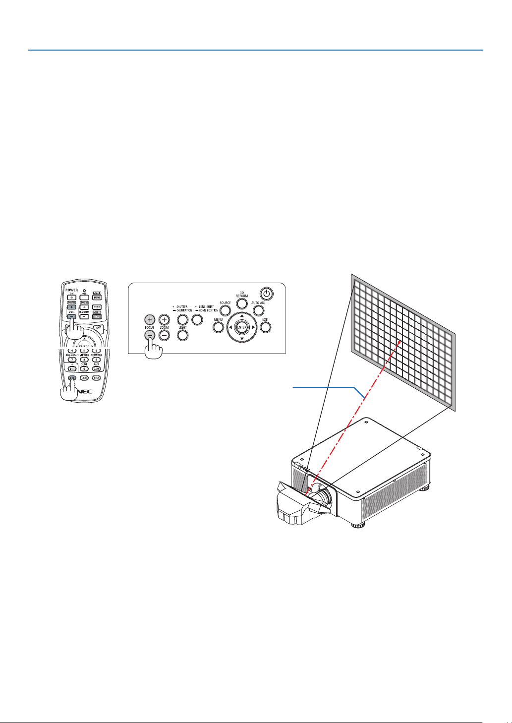
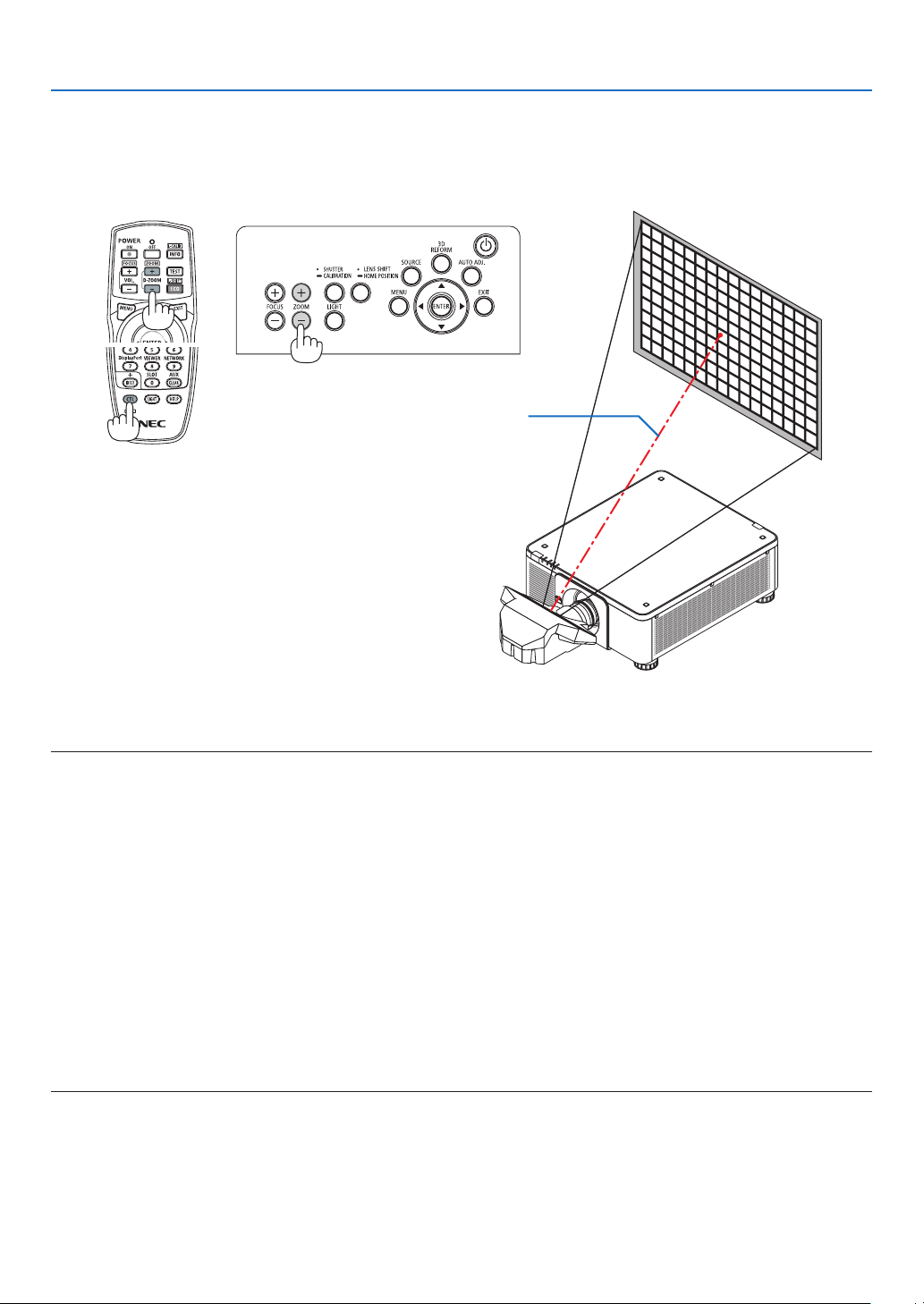
2. Projecting an Image (Basic Operation)
Zoom
Applicablelensunits:NP17ZL/NP18ZL/NP19ZL/NP20ZL/NP21ZL/NP31ZL
1. Press the ZOOM +/− button.
• Ontheremotecontrol,whilepressingontheCTLbutton,presstheD-ZOOM/ZOOM(+)or(−)button.
Thezoomisadjusted.
32
2. Projecting an Image (Basic Operation)
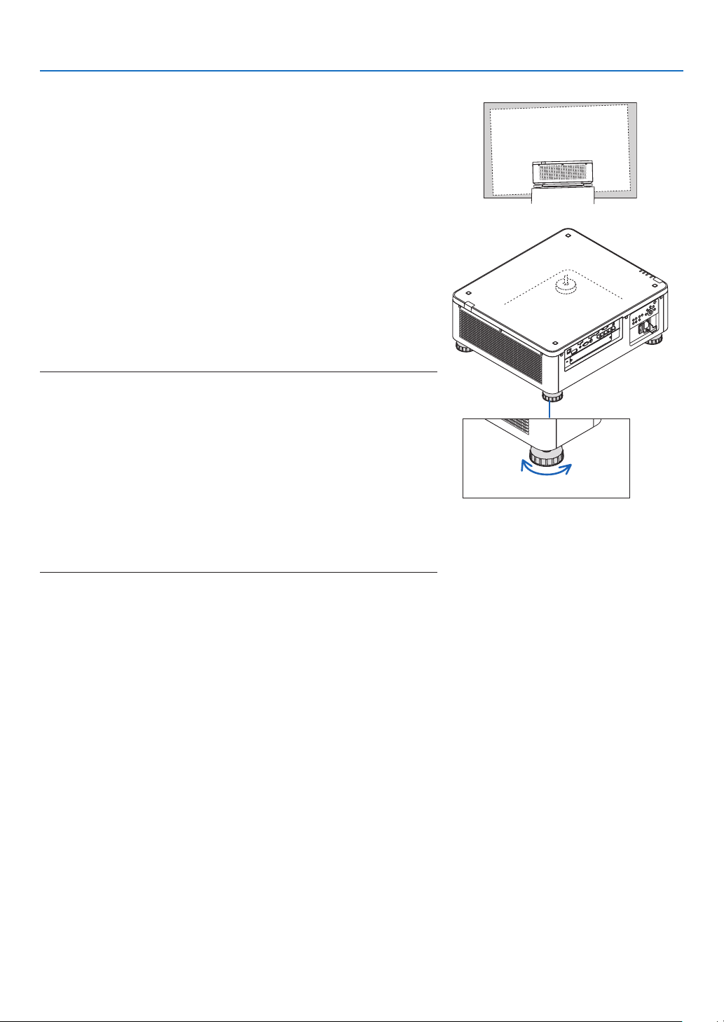
Adjusting the Tilt Foot
1. Thepositionto projectimagemaybeadjusted bythetilt foot
positionedatfourcornersofthecabinetbottom.
Thetiltfootheightcanbeadjustedbyitsturn.
“Toadjusttheheightoftheprojectedimage”
Theheightoftheprojectedimageisadjustedbyturningeitherfront
orreartiltfoot.
“Iftheprojectedimageistilted”
Iftheprojectedimageistilted,turneitherleftorrighttiltfoottoadjust
theimagesothatitislevel.
• Iftheprojectedimageisdistorted,see“3-7CorrectingHorizontal
andVerticalKeystoneDistortion[CORNERSTONE]”(→page42)
and“[GEOMETRICCORRECTION]”(→page105).
• Thetiltfootcanbelengthenedbyamaximumof48mm.
• Thetiltfootcanbeusedtotilttheprojectorbyamaximumof6°.
NOTE:
• Donotlengthenthetiltfootanymorethan50mm/1.9".Doingsowillmakethe
tiltfeet’smountsectionunstableandcouldcausethetiltfeettocomeoffthe
projector.
• Payattentiontolengthenorshortentwotiltfootatfrontatthesametime.Same
for the rear foot, otherwise, the weight of the projector is loaded on one side
anditmaycauseofdamagetoit.
• Donotusethetiltfootforanypurposeotherthanadjustingtheprojector’s
projection angle.
Handlingthetiltfootimproperly,suchascarryingtheprojectorbygraspingthe
tiltfootorhookingitontoawallusingthetiltfoot,coulddamagetheprojector.
• PleasechecklevelofthelensunitWhenthelensunitNP39MLisinstalledon
sincethelensunitmaysligtlyinclineinleftorright.
Tiltfoot
(thereisonemoreintherear)
Up Down
33
2. Projecting an Image (Basic Operation)
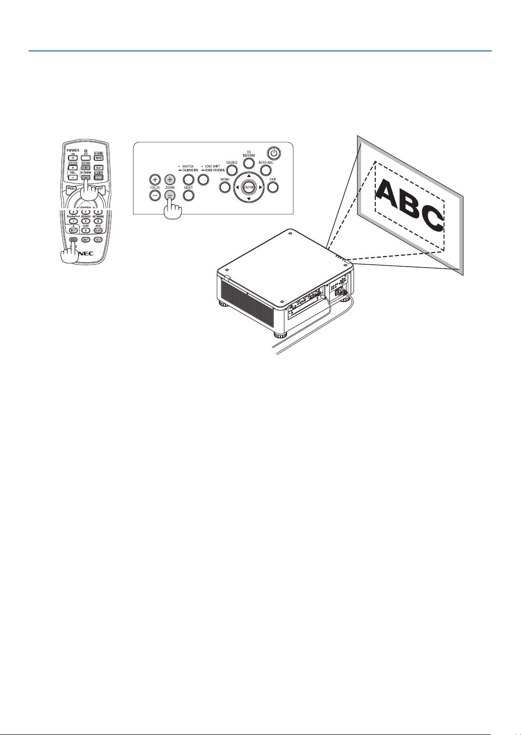
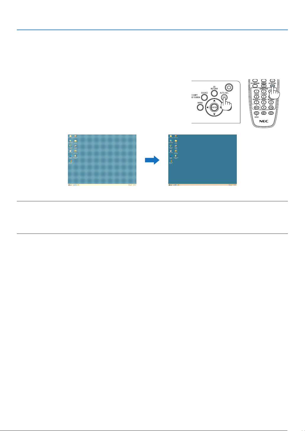
❻ Optimizing Computer Signal Automatically
Adjusting the Image Using Auto Adjust
WhenanimagefromHDMIIN,DisplayPortIN,BNCinputterminal(analogRGB),COMPUTERIN,orHDBaseTis
beingprojected,andtheedgeiscutoffortheimagequalityispoor,thisbuttoncanbeusedtoautomaticallyoptimize
theprojectionimageonthescreen.
PresstheAUTOADJ.buttontooptimizeacomputerimageautomatically.
[Poorpicture] [Adjustedpicture]
NOTE:
Somesignalsmaytaketimetodisplayormaynotbedisplayedcorrectly.
• IftheAutoAdjustoperationcannotoptimizethecomputersignal,trytoadjust[HORIZONTAL],[VERTICAL],[CLOCK],and[PHASE]
manually.(→ page 94, 95)
• Ifyoucannotobtainanoptimizedpicture,referpage190.
34
2. Projecting an Image (Basic Operation)
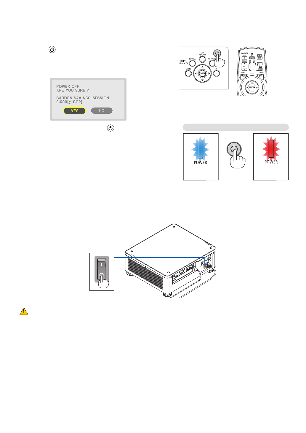
❼ Turning off the Projector
1. Press the (POWER) button on the projector cabinet
or the POWER OFF button on the remote control.
The[POWEROFF/AREYOUSURE?/CARBONSAV-
INGS-SESSION0.000[g-CO2]]messagewillappear.
2. Press one among the ENTER, the (POWER), and the
POWER OFF button.
Whentheprojector is inSTANDBYMODE,thePOWER
indicator lights up red. (When[STANDBY MODE] isin
[NORMAL]setting)
• Ifyoudonotwanttoturnoff,select[NO]by◀/▶button
andpressENTER.
3. Make sure the projector is in STANDBY MODE, then
turnoffthemainpowerswitch(○ OFF)
ThePOWERindicatorwillgooffandthemainpowerwill
turnoff.
• While the POWERindicator is blinkingbluein short
cycles,thepowercannotbeturnedoff.
Power On
Steady blue light
Standby
Steady red light
Press twice
CAUTION:
PartsoftheprojectormaytemporarilyoverheatiftheprojectoristurnedoffwiththemainpowerswitchortheAC
powersupplyisdisconnectedwhiletheprojectorisinoperationorthecoolingfanisrunning.Handlewithcare.

35
2. Projecting an Image (Basic Operation)
NOTE:
• Donotunplugthepowercordfromtheprojectororfromthepoweroutletwhileanimageisbeingprojected.Doingsocould
deterioratetheprojector’sACINterminalorthepowerplug’scontact.ToturnofftheACpowersupplywhentheprojectoris
poweredon,usetheprojector’smainpowerswitch,apowerstripequippedwithaswitch,orabreaker.
• DonotturnoffthemainpowerswitchordisconnecttheACpowersupplywithin10secondsofmakingadjustmentsorsetting
changesandclosingthemenu.Doingsocancauselossofadjustmentsandsettings.
❽ After Use
Preparation:Makesurethattheprojectoristurnedoff.
1. Unplug the power cord.
2. Disconnect any other cables.
3. Mount the lens cap on the lens.
4. Beforemovingtheprojector,screwinthetiltfeetiftheyhavebeenlengthened.
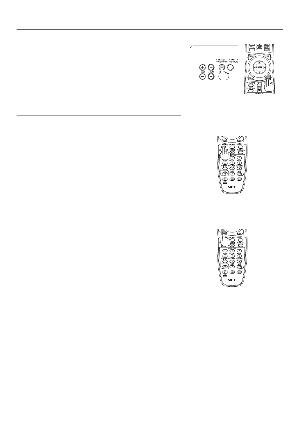
36
3. Convenient Features
❶ Turn off the light of the projector (LENS SHUTTER)
PresstheSHUTTERbutton.
Thelightsourcewillturnofftemporarily.
Pressagaintoallowthescreentobecomeilluminatedagain.
• Anotherwaytoshut thelightsource offisto presstheSHUTTER
buttonontheremotecontrol.
• Youcansettheprojectionlighttograduallyfadeinorout.
NOTE:
• DonotpressandholdtheSHUTTER/CALIBRATIONbuttononthecabinetover
2seconds.Itwillstartthelenscalibration.
❷ Turning off the Image
PresstheAV-MUTEbuttontoturnofftheimageforashortperiodoftime.
Pressagaintorestoretheimage.
TIP:
• Thevideowilldisappearbutnotthemenudisplay.
❸ Turning Off the On-Screen Menu (On-Screen Mute)
ApressoftheON-SCREENbuttonontheremotecontrolwillhidethe
on-screenmenu,thesourcedisplayandothermessages.Pressagain
torestorethem.
TIP:
• Toconrmthattheon-screenmuteisturnedon,presstheMENUbutton.Iftheon-screenmenuisnotdisplayedeventhough
youpresstheMENUbutton,itmeanstheon-screenmuteisturnedon.
• Theon-screenmuteismaintainedevenwhentheprojectoristurnedoff,
• HoldingdowntheMENUbuttonontheprojectorcabinetforatleast10secondswillturnofftheon-screenmute.

37
3. Convenient Features
❹ Freezing a Picture
HoldtheCTLbuttonandpressthePIP/FREEZEbuttontofreezeapicture.
Pressagaintoresumemotion.
NOTE:Theimageisfrozenbuttheoriginalvideoisstillplayingahead.
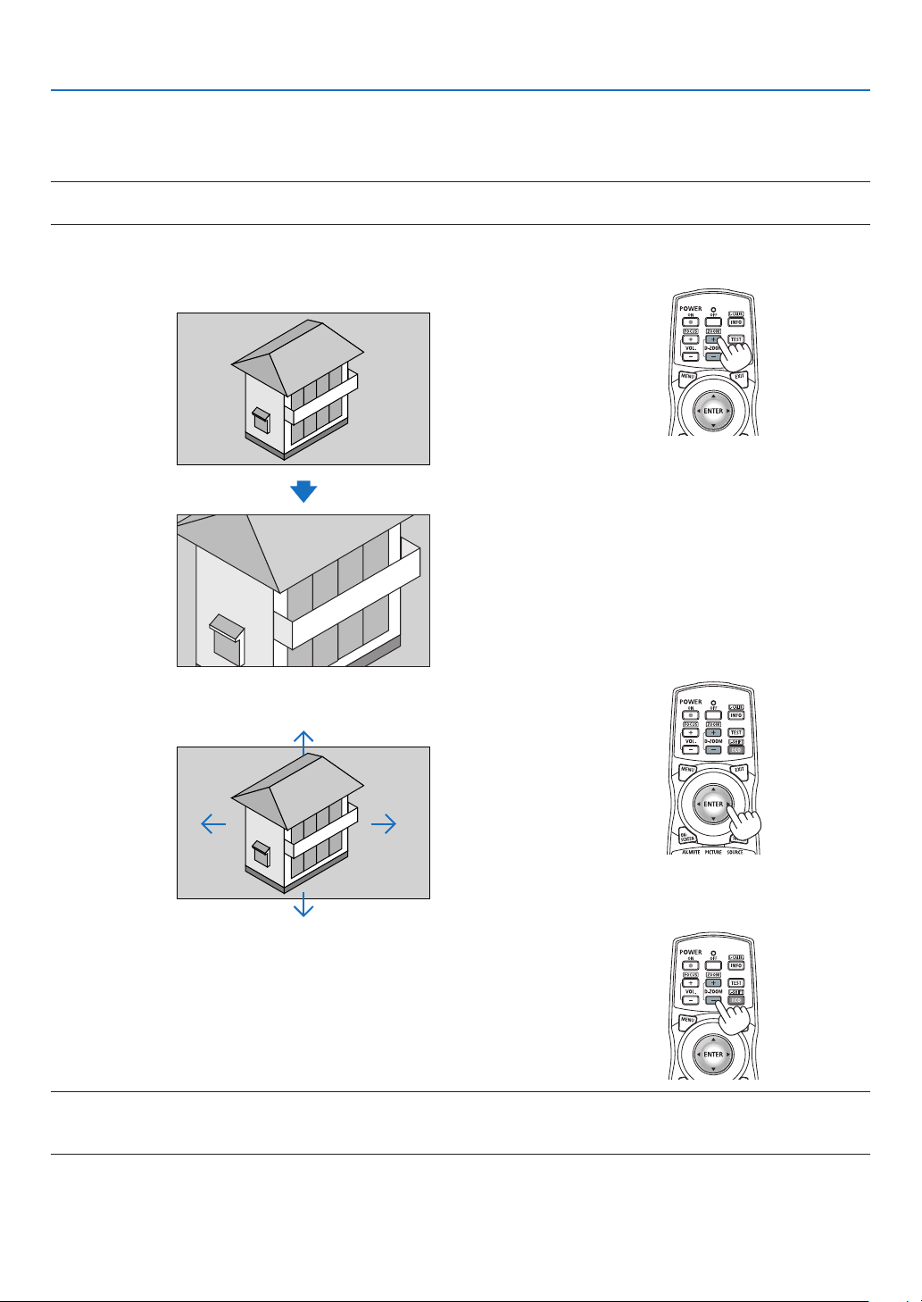
38
3. Convenient Features
❺ Magnifying a Picture
Youcanmagnifythepictureuptofourtimes.
NOTE:
• Dependingonaninputsignal,themaximummagnicationmaybelessthanfourtimes,orthefunctionmayberestricted.
Todoso:
1. PresstheD-ZOOM(+)buttontomagnifythepicture.
2. Press the ▲▼◀▶ button.
Theareaofthemagniedimagewillbemoved
3. Press the D-ZOOM (−) button.
EachtimetheD-ZOOM(−)buttonispressed,theimageisdemagni-
ed.
NOTE:
• Theimagewillbemagniedordemagniedatthecenterofthescreen.
• Displayingthemenuwillcancelthecurrentmagnication.
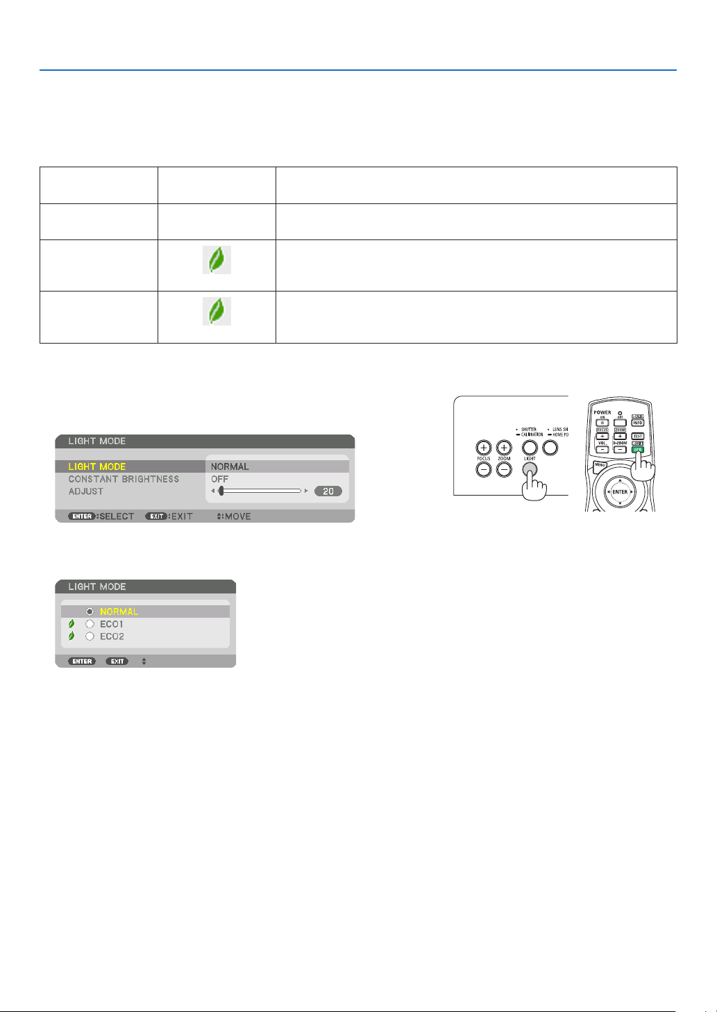
39
3. Convenient Features
❻ Changing LIGHT MODE/Checking Energy-Saving Effect
Using LIGHT MODE [LIGHT MODE]
Wheneither[ECO1]or[ECO2]in[LIGHTMODE]isselected,motionnoiseoftheprojectoriscutdownbylowering
brightnessofitslightsource.Bysavingenergyconsumption,theCO
2
emissionfromthisprojectorcanbereduced.
LIGHTMODE
Iconatthebottom
ofthemenu
Description
NORMAL
100%brightness
Thescreenwillbebrightlylit.
ECO1 Brightnesswillbeatabout80%.
Thecoolingfanwillalsoslowdownaccordingly.
Lowerpowerconsumption
ECO2 Brightnesswillbeatabout50%.
Thecoolingfanwillalsoslowdownaccordingly.
Lowerpowerconsumptionconsiderably
Toturnonthe[LIGHTMODE],dothefollowing:
1. Press LIGHT button on the cabinet.
• Inanotherway,pressECO/L-SHIFTbuttonontheremotecontrol.
The[LIGHTMODE]screenwillbedisplayed.
2. Press the ENTER button.
The[LIGHTMODE]selectionscreenwillbedisplayed.
3. Use the ▼▲ buttons to make a selection, and press the ENTER
button.
Thedisplaywillreturntothe[LIGHTMODE]screenandtheselected
optionwillbeapplied.
PresstheMENUbuttontoreturntotheoriginalscreen.

40
3. Convenient Features
NOTE:
• The[LIGHTMODE]canbechangedbyusingthemenu.
Select[SETUP]→[INSTALLATION(1)]→[LIGHTMODE]→[LIGHTMODE].
• Thelightmodulehoursusedcanbecheckedin[USAGETIME]onthemenu.Select[INFO.]→[USAGETIME].
• Afteralapseof1minutefromwhentheprojectordisplaysablue,blackorlogoscreen,[LIGHTMODE]willautomaticallyswitch
to[ECO].
• Thisprojectorequipsthesensortodetectatmosphericpressureandtemperatureandtheprojectorcontrolsthepowerbasedon
thedetectedvalues.Whentheprojectorisusedinhighaltitudeandhightemperature,thelightsourcebrightnessbecomeslower
regardlessofthesettingforLIGHTMODE.Thisiscalled“ForcedECOMODE”.Pleasereferthebelowtablefortheconditionsand
outputpowerinForcedECOMODE.
Altitudes Atmospherictemperature
5–25°C
(41–77°F)
26–30°C
(78–86°F)
31–35°C
(87–95°F)
36–40°C
(96–104°F)
1600–3000m
(5500–10000ft)
100% 90% 80% 70%
1200–1600m
(4000–5500ft)
100% 90% 80%
0–1200m
(0–4000ft)
100% 80%
• WhentheprojectorisintheForcedLIGHTMODE,thepicturebrightnessdecreasesslightlyandtheTEMP.indicatorlightsorange.
AtthesametimetheThermometersymbol[ ]isdisplayedatthebottomrightofthescreen.
Whentheprojectorcomesbacktonormaltemperature,theForcedECOMODEiscancelledandthe[LIGHTMODE]returnsto
[NORMAL]mode.
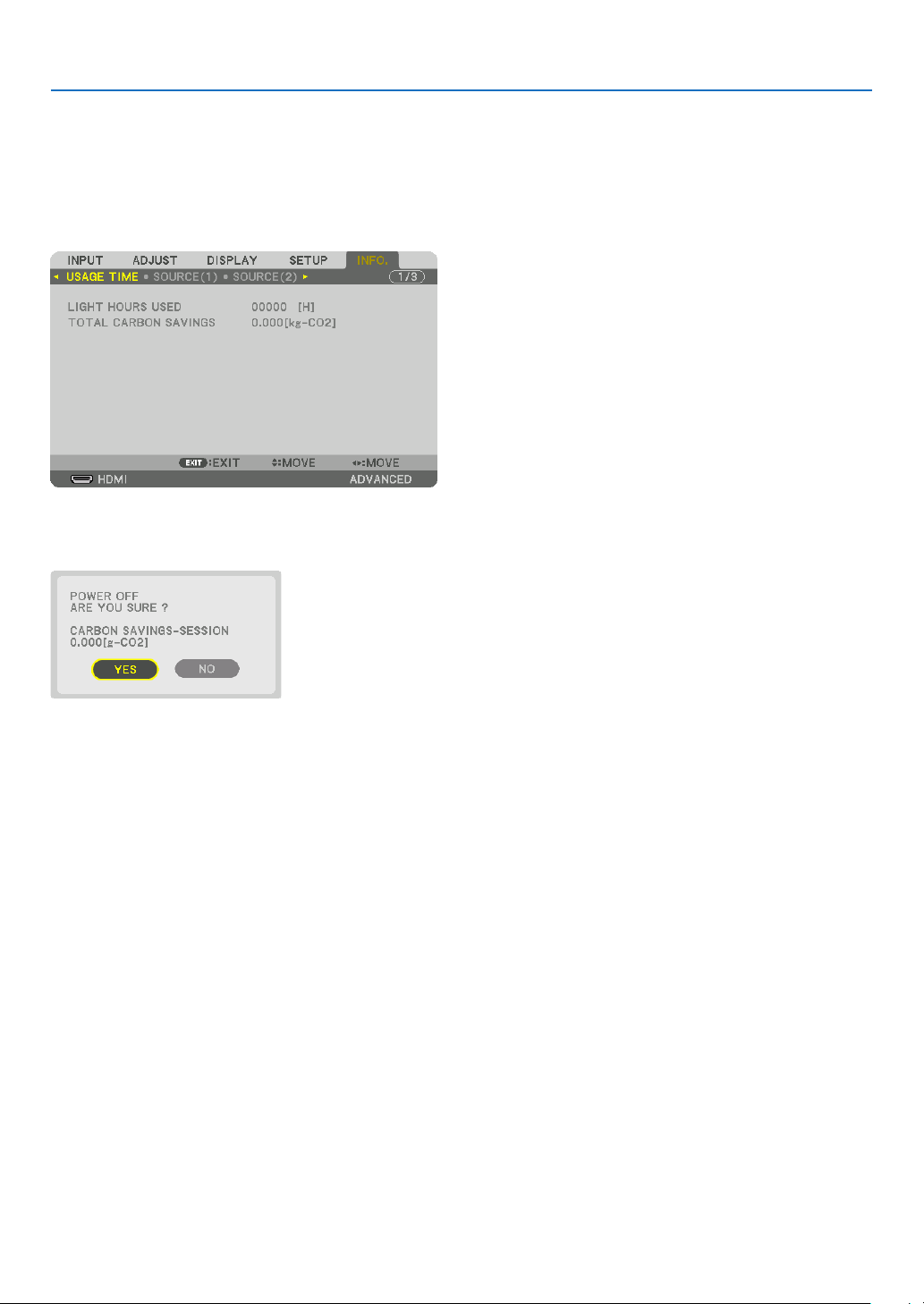
41
3. Convenient Features
Checking Energy-Saving Effect [CARBON METER]
Thisfeaturewillshowenergy-savingeffectintermsofCO
2
emissionreduction(kg)whentheprojector’s[LIGHTMODE]
issettoeither[ECO1]or[ECO2].Thisfeatureiscalledas[CARBONMETER].
Therearetwomessages:[TOTALCARBONSAVINGS]and[CARBONSAVINGS-SESSION].The[TOTALCARBON
SAVINGS]messageshowsthetotalamountofCO
2
emissionreductionfromthetimeofshipmentuptonow.Youcan
checktheinformationon[USAGETIME]from[INFO.]ofthemenu.(→page137)
The[CARBONSAVINGS-SESSION]messageshowstheamountofCO
2
emissionreductionbetweenthetimeof
changingtoLIGHTMODEimmediatelyafterthetimeofpower-onandthetimeofpower-off.The[CARBONSAVINGS-
SESSION]messagewillbedisplayedinthe[POWEROFF/AREYOUSURE?]messageatthetimeofpower-off.
TIP:
• TheformulashownbelowisusedtocalculatetheamountofCO
2
emissionreduction.AmountofCO
2
emissionreduction=(Power
consumptionin[NORMAL]LIGHTMODE–Powerconsumptionincurrentsetting)×CO
2
conversionfactor.*Whenanenergy-
savingLIGHTMODEisselected,ortheLensShutterisused,therewillbeafurtherreductioninCO
2
emission.
* CalculationforamountofCO
2
emissionreductionisbasedonanOECDpublication“CO
2
EmissionsfromFuelCombustion,
2008Edition”.
• The[TOTALCARBONSAVINGS]iscalculatedbasedonsavingsrecordedin15minutesintervals.
• Thisformulawillnotapplytothepowerconsumptionwhichisnotaffectedbywhether[LIGHTMODE]isturnedonoroff.
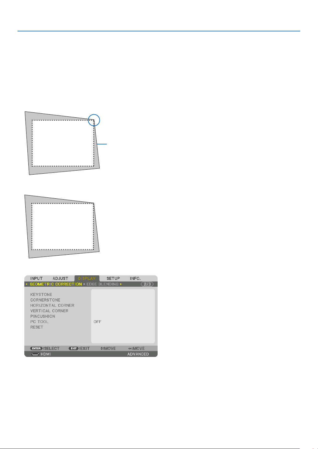
42
3. Convenient Features
❼ Correcting Horizontal and Vertical Keystone Distortion
[CORNERSTONE]
Usethe[CORNERSTONE]featuretocorrectkeystone(trapezoidal)distortiontomakethetoporbottomandtheleft
orrightsideofthescreenlongerorshortersothattheprojectedimageisrectangular.
1. Pressandholdthe3DREFORMbuttonfor2secondsatleasttoresetcurrentadjustments.
Currentadjustmentsfor[GEOMETRICCORRECTION]willbecleared.
2. Projectanimagesothatthescreenissmallerthantheareaoftheraster.
Projectedimage
Thedrawingshowstheupperrightcorner.
3. Pickupanyoneofthecornersandalignthecorneroftheimagewithacornerofthescreen.
4. Press the 3D REFORM button.
Displaythe[GEOMETRICCORRECTION]screenoftheon-screenmenu.
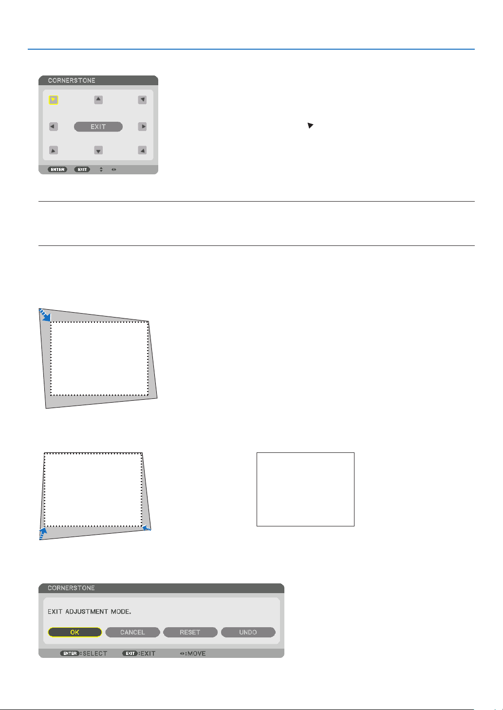
43
3. Convenient Features
5. Press the ▼buttontoalignwiththe[CORNERSTONE]andthenpresstheENTERbutton.
Thedrawingshowstheupperlefticon( )isselected.
Thescreenwillswitchtothe[CORNERSTONE]screen.
NOTE:
• Whena[GEOMETRICCORRECTION]functionotherthan[CORNERSTONE]hasbeensetup,the[CORNERSTONE]screen
willnotbedisplayed.Whenthescreenisnotdisplayed,eitherpressthe3DREFORMbuttonfor2ormoreseconds,orrun
[RESET]in[GEOMETRICCORRECTION]tocleartheadjustmentvalueof[GEOMETRICCORRECTION].
6. Use the ▲▼◀▶ button to select one icon (▲) which points in the direction you wish to move the projected
imageframe.
7. Press the ENTER button.
8. Use the ▲▼◀▶buttontomovetheprojectedimageframeasshownontheexample.
9. PresstheENTERbutton.
10
. Use the ▲▼◀▶ button to select another icon which points in the direction.
11
.Repeatstepsfrom7to10tocompletethecornerstoneadjustment.
12
.Onthe[CORNERSTONE]screen,select[EXIT]orpresstheEXITbuttonontheremotecontrol.
Theconrmationscreenisdisplayed.

44
3. Convenient Features
13
. Press the ◀ or ▶buttontohighlightthe[OK]andpresstheENTERbutton.
Thiscompletesthe[CORNERSTONE]correction.
• Returningtothe[CORNERSTONE]screen,select[CANCEL]andpresstheENTERbutton.
NOTE:
• Eveniftheinstallationangleischangedwhentheprojectoristurnedonagain,thecorrectionvaluesintheprevioustimehasbeen
maintained.
• Carryouteitheroneofthefollowingactionstocleartheadjustmentvalueof[CORNERSTONE].
• InStep12,select[RESET]andthenpresstheENTERbutton.
• Pressthe3DREFORMbuttonfor2ormoreseconds.
• Run[DISPLAY]→[GEOMETRICCORRECTION]→[RESET]intheon-screenmenu.
• UsingCORNERSTONEcorrectioncancausetheimagetobeslightlyblurredbecausethecorrectionismadeelectronically.

45
3. Convenient Features
❽
Preventing the Unauthorized Use of the Projector [SECURITY]
AkeywordcanbesetforyourprojectorusingtheMenutoavoidoperationbyanunauthorizeduser.Whenakeyword
isset,turningontheprojectorwilldisplaytheKeywordinputscreen.Unlessthecorrectkeywordisentered,thepro-
jectorcannotprojectanimage.
•The[SECURITY]settingcannotbecancelledbyusingthe[RESET]ofthemenu.
To enable the Security function:
1. Press the MENU button.
Themenuwillbedisplayed.
2. Press the ▶buttontwicetoselect[SETUP]andpressthe▼buttonortheENTERbuttontoselect[MENU].
3. Press the ▶buttontoselect[CONTROL].
4. Press the ▼buttonthreetimestoselect[SECURITY]andpresstheENTERbutton.
TheOFF/ONmenuwillbedisplayed.
5. Press the ▼buttontoselect[ON]andpresstheENTERbutton.
The[SECURITYKEYWORD]screenwillbedisplayed.
6. Typeyourkeywordinacombinationofthefour▲▼◀▶ buttons and press the ENTER button.
NOTE:Akeywordmustbe4to10digitsinlength.
The[CONFIRMKEYWORD]screenwillbedisplayed.
NOTE:Makeanoteofyourpasswordandstoreitinasafeplace.
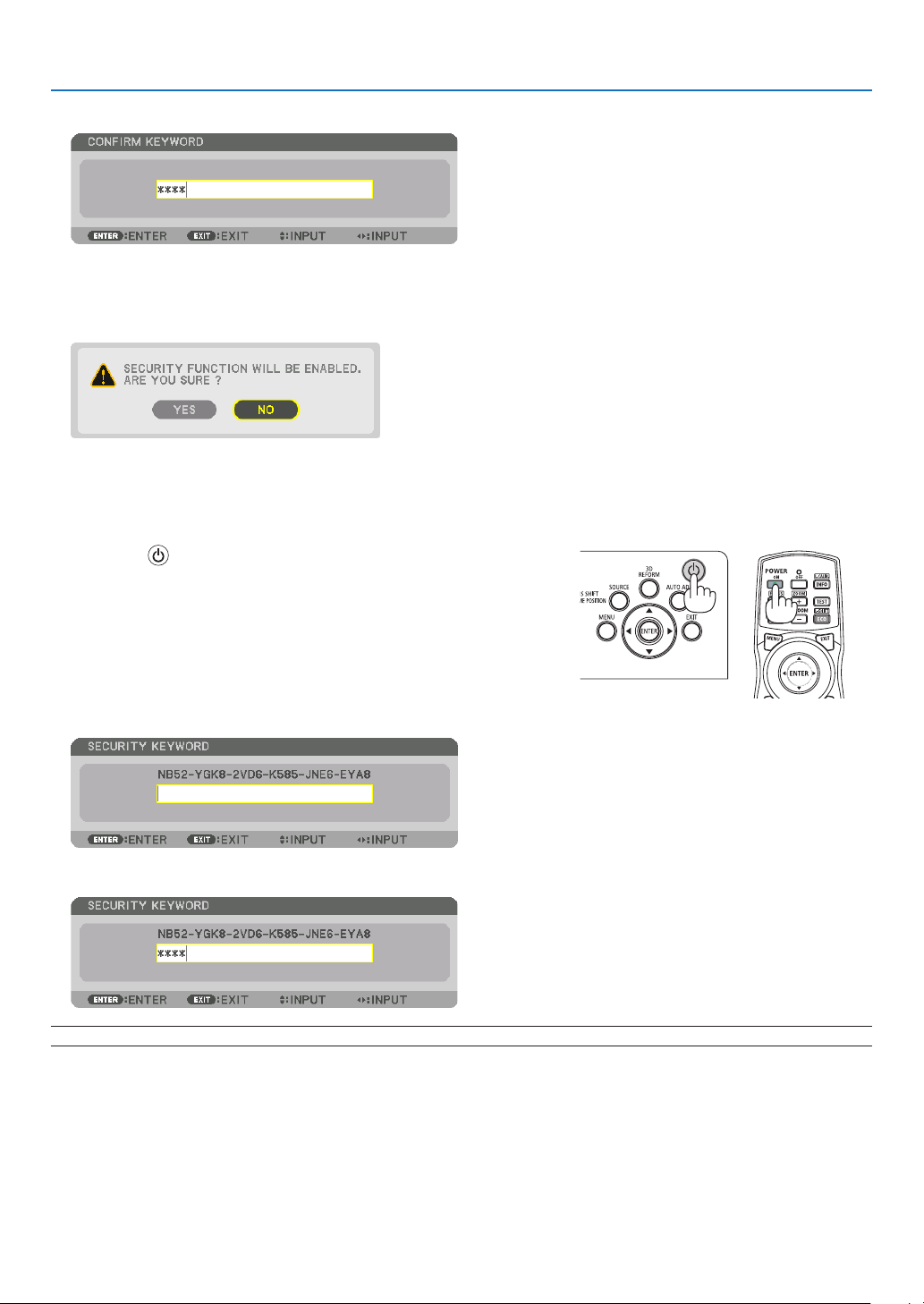
46
3. Convenient Features
7. Typeyourkeywordinthesamecombinationof▲▼◀▶ buttons and press the ENTER button.
Theconrmationscreenwillbedisplayed.
8. Select[YES]andpresstheENTERbutton.
TheSECURITYfunctionhasbeenenabled.
Toturnontheprojectorwhen[SECURITY]isenabled:
1. Press the button.
• Ifusingtheremotecontrol,pressthePOWERONbutton.
Theprojectorwillbeturnedonanddisplayamessagetotheeffect
thattheprojectorislocked.
2. Press the MENU button.
3. Type in the correct keyword and press the ENTER button. The projector will display an image.
NOTE:Thesecuritydisablemodeismaintaineduntilthemainpoweristurnedofforunpluggingthepowercord.
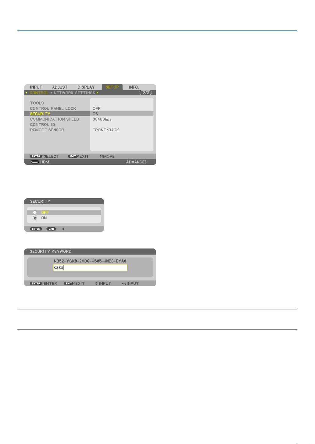
47
3. Convenient Features
TodisabletheSECURITYfunction:
1. Press the MENU button.
Themenuwillbedisplayed.
2. Select[SETUP]→[CONTROL]→[SECURITY]andpresstheENTERbutton.
TheOFF/ONmenuwillbedisplayed.
3. Select[OFF]andpresstheENTERbutton.
TheSECURITYKEYWORDscreenwillbedisplayed.
4. Type in your keyword and press the ENTER button.
Whenthecorrectkeywordisentered,theSECURITYfunctionwillbedisabled.
NOTE:Ifyouforgetyourkeyword,contactyourdealer.Yourdealerwillprovideyouwithyourkeywordinexchangeforyourrequest
code.YourrequestcodeisdisplayedintheKeywordConrmationscreen.Inthisexample[NB52-YGK8-2VD6-K585-JNE6-EYA8]
is a request code.
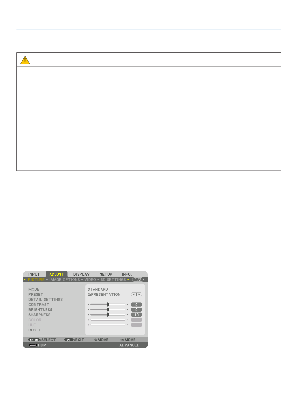
48
3. Convenient Features
❾ Projecting 3D videos
ThisprojectorsupportsDLP-Linkglassesand3Demitter.
CAUTION
Health precautions
Beforeuse,pleasemakesuretoreadanyhealthprecautionsthatmaybestatedintheoperatingmanualsenclosed
withthe3Deyewearand3Dvideosoftware(Blu-rayplayer,games,computeranimationles,etc.).
Pleasetakenoteofthefollowinginordertoavoidadversehealtheffects.
• Pleasedonotusethe3Deyewearforpurposesotherthantowatch3Dvideos.
• Pleasekeepadistanceofatleast2mawayfromthescreenwhenwatchingvideos.Watchingavideotooclose
tothescreenwillincreaseeyefatigue.
• Pleasedonotwatchvideoscontinuouslyforalongperiodoftime.Pleasetakea15minutes’breakafterevery
hourofwatching.
• Pleaseconsultadoctorbeforewatchingifyouoranyofyourfamilymembershaveahistoryofsufferingfrom
seizurescausedbylightsensitivity.
• Pleasestopwatchingimmediatelyandtakearestwhenyoufeelphysicallyunwellwhilewatching(vomiting,gid-
diness,nausea,headaches,soreeyes,blurredvision,crampsanddumbnessinthelimbs,etc.).Pleaseconsult
adoctorifthesymptomspersist.
• Pleasewatcha3Dvideodirectlyinfrontofthescreen.Ifyouwatcha3Dvideoobliquelyfromthesides,thismay
resultinphysicalandeyefatigue.
Procedure to watch 3D videos using this projector
ThedescriptionhereareforDLP
®
Link.[DLP®Link]isdefaultsettingfor[3DGLASSES]atthefactory.
3D eyewear and 3D emitter preparations
UseDLP
®
Linkglassesorothercompatiblecommercially-availableliquidcrystalshutterspectacles.
1. Connectthevideodevicetotheprojector.
2. Switch on the projector.
3. Runthe3Dvideosoftware.
The3Dvideowillbeprojected.
Thedefaultfactorysettingis[AUTO].When3Dimageisnotprojected,itmaycauseinputsignaldoesnotcontain
3Ddetectionsignaloritcannotbedetectedbythisprojector.Inthiscase,pleasesetuptheformatmanually.
(1)PresstheMENUbutton.
TheMENUwillbedisplayed.
(2)Pressthe▶button,select[ADJUST],thenpressENTER.
[PICTURE]willbehighlighted.
(3)Usethe▶buttontoselect[3DSETTINGS].
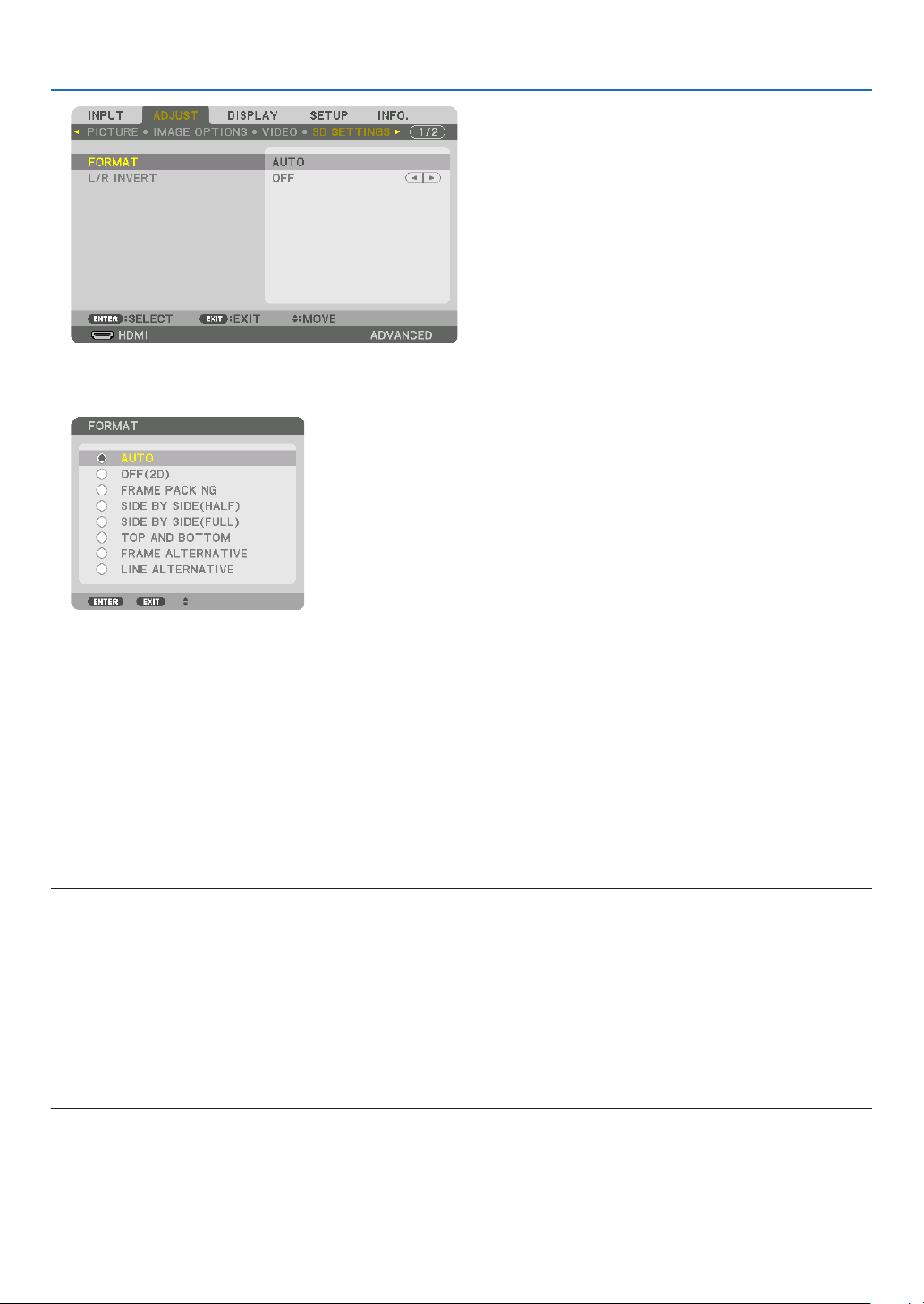
49
3. Convenient Features
The[3DSETTINGS]screenwillbedisplayed.
(4)Usethe▼buttontoalignthecursorwith[FORMAT],thenpressENTER.
The[FORMAT]screenwillbedisplayed.
(5)Usethe▼/▲buttonstoalignthecursoratoneamongformatoptions,thenpressENTERforsettingitup.
Thedisplaywillreturntothe[FORMAT]screen.
PresstheMENUbuttontoreturntotheoriginalscreen.
• The3Dcautionmessagescreenwillbedisplayedwhenswitchingtoa3Dvideo(defaultfactorysettingwhen
shipped).Pleasereadthe“HealthPrecautions”onthepreviouspagetowatchvideosinthecorrectmanner.The
screenwilldisappearafter60secondsorwhentheENTERbuttonispressed.(→page113)
4. Turnonthepowersupplyofthe3Deyewearandweartheeyeweartowatchthevideo.
Anormalvideowillbeshownwhena2Dvideoisinput.
Towatcha3Dvideoin2D,select[OFF(2D)]inthe[FORMAT]screenmentionedabovein(3).
NOTE:
• If3Dcontentisplayedbackonyourcomputerandtheperformanceispoor,itmaybecausedbytheCPUorgraphicschip.Inthis
caseyoumayhavedifcultyseeingthe3Dimagesastheywereintended.Checktoseeifyourcomputermeetstherequirements
providedinyouruser’smanualincludedwithyour3Dcontent.
• TheDLP
®
Linkcompatible3Deyeglassesallowyoutoview3Dimagesbyreceivingsynchsignals,whichareincludedinlefteye
andrighteyeimages,reectedfromthescreen.Dependingonenvironmentsorconditionssuchastheambientbrightness,screen
sizeorviewingdistance,the3Deyeglassesmayfailtoreceivesynchsignals,causingpoor3Dimages.
• Whenthe3Dmodeisenabled,theKeystonecorrectionrangewillbenarrower.
• Whenthe3Dmodeisenabled,thefollowingsettingsareinvalid.
[WALLCOLOR],[PRESET],[REFERENCE],[COLORTEMPERATURE],[DYNAMICCONTRAST],[BrilliantColor]
• Signalsotherthanthoselistedin“CompatibleInputSignalList”onpage178 and 179willbeoutofrangeordisplayedin2D.

50
3. Convenient Features
Using a 3D emitter
Thisprojectorcanbeusedtowatchvideosin3Dusingcommercially-availableactiveshutter-type3Deyewear.In
ordertosynchronizethe3Dvideoandeyewear,acommercially-available3Demitterneedstobeconnectedtothe
projector(ontheprojectorside).
The3Deyewearreceivesinformationfromthe3Demitterandperformsopeningandclosingontheleftandright.
3D eyewear and 3D emitter preparations
Pleaseuseanactiveshutter-type3DeyewearthatconformswiththeVESAstandard.
Acommercially-availableRFtypemadebyXpandisrecommended.
3D eyewear ������������ Xpand X105-RF-X2
3D emitter
�������������� Xpand AD025-RF-X1
Connectyour3Demittertothe3DSYNCterminaloftheprojector.
Change[3DGLASSES]settingto[OTHERS].
NOTE:
• Uponswitchingto3Dimage,thefollowingfunctionswillbecancelledanddisabled.[BLANKING],[PIP/PICTUREBYPICTURE],
[GEOMETRICCORRECTION],[EDGEBLENDING]([GEOMETRICCORRECTION]and[EDGEBLENDING]adjustmentvalueswill
bemaintained.)
• Theoutputmaynotautomaticallyswitchtoa3Dvideodependingonthe3Dinputsignal.
• ChecktheoperatingconditionsdescribedintheusermanualoftheBlu-rayplayer.
• PleaseconnecttheDINterminalofthe3Demittertothe3DSYNCofthemainprojector.
• The3Deyewearallowsvideostobeviewedin3Dbyreceivingsynchronizedopticalsignalsoutputfromthe3Demitter.
Asaresult,the3Dimagequalitymaybeaffectedbyconditionssuchasthebrightnessofthesurroundings,screensize,viewing
distance, etc.
• Whenplayinga3Dvideosoftwareonacomputer,the3DimagequalitymaybeaffectedifthecomputerCPUandgraphicschip
performancearelow.Pleasechecktherequiredoperatingenvironmentofthecomputerthatisstatedintheoperatingmanual
attachedtothe3Dvideosoftware.
• Dependingonthesignal,[FORMAT]and[L/RINVERT]maynotbeabletobeselected.Pleasechangethesignalinthatcase.

51
3. Convenient Features
When videos cannot be viewed in 3D
Pleasecheckthefollowingpointswhenvideoscannotbeviewedin3D.
Pleasealsoreadtheoperatingmanualattachedtothe3Deyewear.
Possible reasons Solutions
The selected signal does not support 3D output� Please change the video signal input to one that supports 3D�
The format for the selected signal is turned to [OFF(2D)]� Please change the format in the on-screen menu to [AUTO] or a
format that supports 3D�
A eyewear that is not supported by the projector is being used� Please purchase a commercially-available 3D eyewear or 3D emit-
ter (recommended)� (→ page 50)
Please check the following points when a video cannot be viewed
in 3D using a 3D eyewear that is supported by the projector�
The power supply of the 3D eyewear is turned off� Please turn on the power supply of the 3D eyewear�
The internal battery of the 3D eyewear is flat� Please charge or replace the battery�
The viewer is located too far away from the screen� Please get closer to the screen until the video can be seen in 3D�
Please turn the L/R INVERT in the on-screen menu to [OFF]�
Due to multiple 3D projectors working at the same time in the
vicinity, the projectors may interfere with one another� Alter-
natively, there may be a bright light source near the screen�
Please maintain sufficient distance between the projectors�
Please keep the light source away from the screen�
Please turn the L/R INVERT in the on-screen menu to [OFF]�
Please check the following points when videos played back on the
computer cannot be viewed in 3D�
Settings on the computer are not compatible with 3D video
playback�
Check to make sure that settings on the computer meet require-
ments for 3D video playback�
Image resolution on the computer cannot be recognized by
the projector as 3D video�
Change the image resolution on the computer to one that the
projector can recognize as 3D video�
The vertical scan rate on the computer cannot be recognized
by the projector as 3D video�
Change the vertical scan rate on the computer to 60 Hz or 120 Hz�
There is an obstacle between the optical receiver of the 3D eye-
wear and the 3D emitter�
Please remove the obstacle�
The 3D format of the 3D video contents is not supported� Please check with the company selling the 3D video contents�

52
3. Convenient Features
❿ Controlling the Projector by Using an HTTP Browser
Overview
TheHTTPServerfunctionprovidessettingsandoperationsfor:
1. Settingforwirednetwork(NETWORKSETTINGS)
TousewiredLANconnection,connecttheprojectortothecomputerwithacommerciallyavailableLANcable.(→
page152)
2. Setting Alert Mail (ALERT MAIL)
Whentheprojectorisconnectedtoawirednetwork,errormessageswillbesentviae-mail.
3. Operating the projector
Poweron/off,selectinginput,volumecontrolandpictureadjustmentsarepossible.
4. SettingPJLinkPASSWORDandAMXBEACON
AccesstotheHTTPserverfunctionisavailable:
• StarttheWebbrowseronthecomputerviathenetworkconnectedtotheprojectorandenterthefollowing
URL :
http://<the projector’s IP address> /index.html
TIP:ThefactorysettingIPaddressis[DHCPON].
NOTE:
• Tousetheprojectorinanetwork,consultwithyournetworkadministratoraboutnetworksettings.
• Thedisplay’sorbutton’sresponsecanbesloweddownoroperationmaynotbeaccepteddependingthesettingsofyournetwork.
Shouldthishappen,consultyournetworkadministrator.Theprojectormaynotrespondifitsbuttonsarerepeatedlypressedin
rapidintervals.Shouldthishappen,waitamomentandrepeat.Ifyoustillcan’tgetanyresponse,turnoffandbackontheprojec-
tor.
• IfthePROJECTORNETWORKSETTINGSscreendoesnotappearinthewebbrowser,presstheCtrl+F5keystorefreshyourweb
browser(orclearthecache).
• Thisprojectoruses“JavaScript”and“Cookies”andthebrowsershouldbesettoacceptthesefunctions.Thesettingmethodwill
varydependingontheversionofbrowser.Pleaserefertothehelplesandtheotherinformationprovidedinyoursoftware.
Preparation before Use
ConnecttheprojectortoacommerciallyavailableLANcablebeforeengaginginbrowseroperations.(→page152)
Operationwithabrowserthatusesaproxyservermaynotbepossibledependingonthetypeofproxyserverandthe
settingmethod.Althoughthetypeofproxyserverwillbeafactor,itispossiblethatitemsthathaveactuallybeenset
willnotbedisplayeddependingontheeffectivenessofthecache,andthecontentssetfromthebrowsermaynotbe
reectedinoperation.Itisrecommendedthataproxyservernotbeusedunlessitisunavoidable.
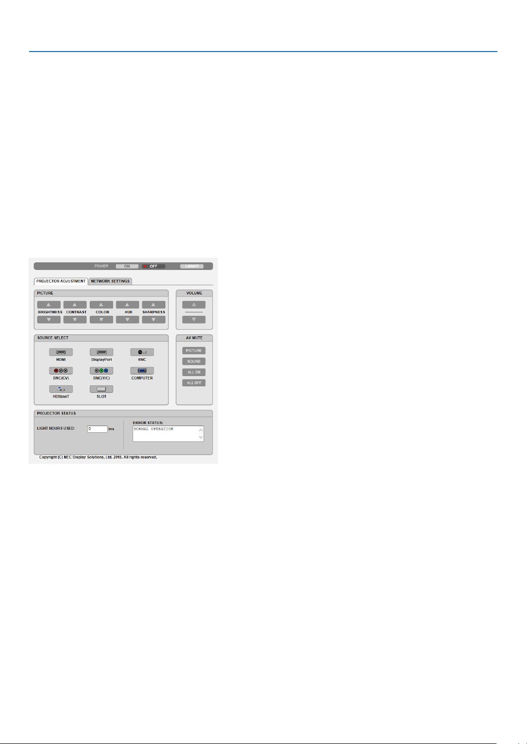
53
3. Convenient Features
Handling of the Address for Operation via a Browser
RegardingtheactualaddressthatisenteredfortheaddressorenteredtotheURLcolumnwhenoperationofthepro-
jectorisviaabrowser,thehostnamecanbeusedasitiswhenthehostnamecorrespondingtotheIPaddressofthe
projectorhasbeenregisteredtothedomainnameserverbyanetworkadministrator,orthehostnamecorresponding
totheIPaddressoftheprojectorhasbeensetinthe“HOSTS”leofthecomputerbeingused.
Example1:Whenthehostnameoftheprojectorhasbeensetto“pj.nec.co.jp”,accessisgainedtothenetwork
settingbyspecifying
http://pj.nec.co.jp/index.html
fortheaddressortheentrycolumnoftheURL.
Example2:WhentheIPaddressoftheprojectoris“192.168.73.1”,accessisgainedtothenetworksettingby
specifying
http://192.168.73.1/index.html
fortheaddressortheentrycolumnoftheURL.
PROJECTOR ADJUSTMENT
POWER:Thiscontrolsthepoweroftheprojector.
ON ������������������������� Power is switched on�
OFF ������������������������ Power is switched off�
VOLUME:Cannotbeusedforthisdevice.
AV-MUTE:Thiscontrolsthemutefunctionoftheprojector.
PICTURE ON ���������� Mutes the video�
PICTURE OFF ��������� Cancels the video muting�
SOUND ON ������������ Cannot be used for this device�
SOUND OFF ����������� Cannot be used for this device�
ALL ON ������������������ Mutes the video functions�
ALL OFF ����������������� Cancels the muting of the video functions�

54
3. Convenient Features
PICTURE:Controlsthevideoadjustmentoftheprojector.
BRIGHTNESS ▲ ���� Increases the brightness adjustment value�
BRIGHTNESS ▼ ���� Decreases the brightness adjustment value�
CONTRAST ▲ �������� Increases the contrast adjustment value�
CONTRAST ▼ �������� Decreases the contrast adjustment value�
COLOR ▲ �������������� Increases the color adjustment value�
COLOR ▼ �������������� Decreases the color adjustment value�
HUE ▲ ������������������� Increases the hue adjustment value�
HUE ▼ ������������������� Decreases the hue adjustment value�
SHARPNESS ▲ ����� Increases the sharpness adjustment value�
SHARPNESS ▼ ����� Decreases the sharpness adjustment value�
• Thefunctionsthatcanbecontrolledwillvarydependingonthesignalbeinginputtotheprojector.(→page93)
SOURCESELECT:Thisswitchestheinputterminaloftheprojector.
HDMI ��������������������� Switches to the HDMI IN terminal�
DisplayPort ������������ Switches to the DisplayPort IN�
BNC ����������������������� Switch to BNC video input�
BNC(CV) ���������������� Switch to BNC (CV) video input�
BNC(Y/C) ��������������� Switch to BNC (Y/C) video input�
COMPUTER ����������� Switches to the COMPUTER IN terminal�
HDBaseT ���������������� Switch to image input sent from a transmission device that supports HDBaseT�
SLOT ���������������������� The projector switches to video input from the optional board when an optional board (sold separately) is
equipped on�
PROJECTORSTATUS:Thisdisplaystheconditionoftheprojector.
LIGHT HOURS USED ����������Displays how many hours the light module has been used�
ERROR STATUS ������������������Displays the status of errors occurring within the projector�
LOGOFF:Loggingoffyourprojectorandreturningtotheauthenticationscreen(LOGONscreen).

55
3. Convenient Features
NETWORK SETTINGS
•SETTINGS
WIRED
SETTING SetforwiredLAN.
APPLY ApplyyoursettingstowiredLAN.
PROFILE1/PROFILE2 TwosettingscanbesetforwiredLANconnection.SelectPROFILE1orPROFILE2.
DISABLE TurnoffwiredLANconnection
DHCPON AutomaticallyassignIPaddress,subnetmask,andgatewaytotheprojectorfromyour
DHCPserver.
DHCPOFF SetIPaddress,subnetmask,andgatewaytotheprojectorassignedbyyournetwork
administrator.
IPADDRESS SetyourIPaddressofthenetworkconnectedtotheprojector.
SUBNETMASK Setyoursubnetmasknumberofthenetworkconnectedtotheprojector.
GATEWAY Setthedefaultgatewayofthenetworkconnectedtotheprojector.
AUTODNSON DHCPserverwillautomaticallyassignIPaddressofDNS serverconnectedtothe
projector.
AUTODNSOFF SetyourIPaddressofDNSserverconnectedtotheprojector.

56
3. Convenient Features
•NAME
PROJECTORNAME Enteranameforyour projector sothatyourcomputercanidentify theprojector. A
projectornamemustbe16charactersorless.
TIP:Projectornamewillnotbeaffectedevenwhen[RESET]isdonefromthemenu.
HOSTNAME Enterthehostnameofthenetworkconnectedtotheprojector.Ahostnamemustbe
15orless.
DOMAINNAME Enterthedomainnameofthenetworkconnectedtotheprojector.Adomainname
mustbe60charactersorless.
•ALERTMAIL
ALERTMAIL Thisoptionwillnotifyyourcomputeroferrormessagesviae-mailwhenusingwiredLAN.
PlacingacheckmarkwillturnontheAlertMailfeature.
ClearingacheckmarkwillturnofftheAlertMailfeature.
Sampleofamessagetobesentfromtheprojector:
Subject:[Projector]ProjectorInformation
THECOOLINGFANHASSTOPPED.
[INFORMATION]
PROJECTORNAME:PX803ULSeries
LIGHTHOURSUSED:0000[H]
SENDER’SADDRESS Entersender’saddress.
SMTPSERVERNAME EntertheSMTPservernametobeconnectedtotheprojector.
RECIPIENT’SADDRESS
1,2,3
Enteryourrecipient’saddress.Uptothreeaddressescanbeentered.
TESTMAIL Sendatestmailtocheckwhetheryoursettingsarecorrectornot
NOTE:
• Ifyouexecuteatest,youmaynotreceiveanAlertmail.Shouldthishappen,checkifnetwork
settings are correct.
• Ifyouenteredanincorrectaddressinatest,youmaynotreceiveanAlertmail.Shouldthis
happen,checkiftheRecipient’sAddressiscorrect.
SAVE Clickthisbuttontosaveyoursettingstotheprojector’smemory.

57
3. Convenient Features
•NETWORKSERVICE
PJLinkPASSWORD SetapasswordforPJLink*.Apasswordmustbe32charactersorless.Donotforget
yourpassword.However,ifyouforgetyourpassword,consultwithyourdealer.
HTTPPASSWORD SetapasswordforHTTPserver.Apasswordmustbe10charactersorless.
Whenapasswordissetup,youwillbepromptedforyourusername(arbitrary)and
passwordduringLOGON.
AMXBEACON TurnonorofffordetectionfromAMXDeviceDiscoverywhenconnectingtothenetwork
supportedbyAMX’sNetLinxcontrolsystem.
TIP:
WhenusingadevicethatsupportsAMXDeviceDiscovery,allAMXNetLinxcontrolsystemwill
recognizethedeviceanddownloadtheappropriateDeviceDiscoveryModulefromanAMXserver.
PlacingacheckmarkwillenabledetectingtheprojectorfromAMXDeviceDiscovery.
ClearingacheckmarkwilldisabledetectingtheprojectorfromAMXDeviceDiscovery.
ExtronXTP SetforconnectingthisprojectortotheExtronXTPtransmitter.Placingacheckmark
willenabletoconnectwiththeXTPtransmitter.Clearingacheckmarkwilldisableto
connectwiththeXTPtransmitter.
NOTE:Ifyouforgetyourpassword,contactyourdealer.
*WhatisPJLink?
PJLinkisastandardizationofprotocolusedforcontrollingprojectorsofdifferentmanufacturers.Thisstandard
protocolisestablishedbyJapanBusinessMachineandInformationSystemIndustriesAssociation(JBMIA)in2005.
TheprojectorsupportsallthecommandsofPJLinkClass1.
SettingofPJLinkwillnotbeaffectedevenwhen[RESET]isdonefromthemenu.
CRESTRON
•ROOMVIEWformanagingfromthecomputer.
DISABLE DisablesROOMVIEW.
ENABLE EnablesROOMVIEW.
•CRESTRONCONTROLformanagingfromthecontroller.
DISABLE DisablesCRESTRONCONTROL.
ENABLE EnablesCRESTRONCONTROL.
IPADDRESS SetyourIPaddressofCRESTRONSERVER.
IPID SetyourIPIDofCRESTRONSERVER.
•INFORMATION
WIREDLAN DisplayalistofsettingsofwiredLANconnection.
UPDATE Reectsettingswhentheyarechanged.
TIP:TheCRESTRONsettingsarerequiredonlyforusewithCRESTRONROOMVIEW.
Formoreinformation,visithttp://www.crestron.com

58
3. Convenient Features
⓫ Storing Changes for Lens Shift, Zoom, and Focus [LENS
MEMORY]
TheadjustedvaluescanbestoredinprojectormemorywhenusingtheLENSSHIFT,ZOOMandFOCUSbuttons
oftheprojector.Adjustedvaluescanbeappliedtothesignalyouselected.Thiswilleliminatetheneedtoadjustlens
shift,focus,andzoomatthetimeofsourceselection.Therearetwowaystosaveadjustedvaluesforlensshift,zoom,
andfocus.
Functionname Description page
REF.LENSMEMORY Adjustedvaluescommontoallinputsignals.Atthetimeofinstallation,
twokindsofadjustedvaluescanberecorded.
Ifnoadjustedvaluesarestoredin[LENSMEMORY],adjustedvalues
fromtheselectedprole([REF.LENSMEMORY])willbeappliedfor
lensadjustment.
→page118
LENSMEMORY Adjustedvaluesforeachinputsignal.
Usetheadjustedvaluesforthesignalwithadifferentaspectratioor
resolution.Theadjustedvaluescanbeappliedatthetimeofsource
selection.
→page101
NOTE:
• ForusingthelensunitNP16FL,NP17ZL,NP18ZL,NP19ZL,NP20ZL,NP21ZL,andNP31ZL,besuretocarryout[LENSCALIBRA-
TION]afterreplacingthelensunit.(→ page 18, 118)
• Forthelensunit,NP16FL,thestorablevalueas[LENSMEMORY]featureisfor[FOCUS]only.
• The[LENSMEMORY]featureisnotavailableforthelensunit,NP39ML.
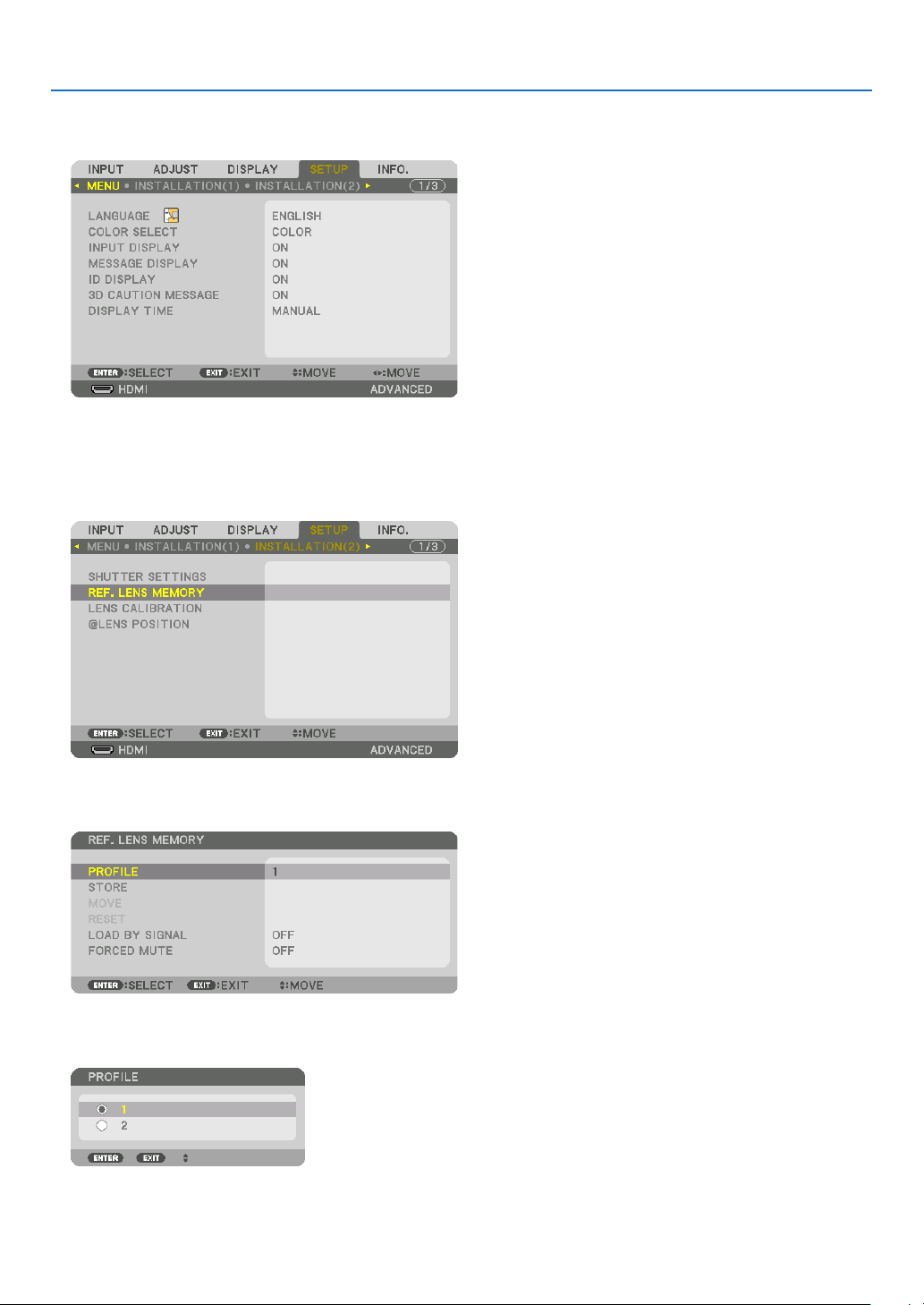
59
3. Convenient Features
To store your adjusted values in [REF. LENS MEMORY]:
1. Press the MENU button.
Themenuwillbedisplayed.
2. Press the ▶buttontoselect[SETUP]andpresstheENTERbutton.
3. Press the ▶buttontoselect[INSTALLATION(2)].
4. Press the ▼buttontoselect[REF.LENSMEMORY]andpresstheENTERbutton.
The[REF.LENSMEMORY]screenwillbedisplayed.
5. Makesure[PROFILE]ishighlighted,thenpresstheENTERbutton.
The[PROFILE]selectionscreenappears.
6. Press the ▼/▲buttonstoselectthe[PROFILE]number,thenpresstheENTERbutton.
Returntothe[REF.LENSMEMORY]settingsscreen.
7. Select[STORE]andpresstheENTERbutton.

60
3. Convenient Features
Theconrmationscreenwillbedisplayed.
8. Press the ◀buttontoselectand[YES]andpresstheENTERbutton.
Selecta[PROFILE]numberandsavetheadjusted[LENSSHIFT],[ZOOM],and[FOCUS]valuestoit.
• The[FORCEDMUTE]settingstopsprojectionduringlensshift.(→page118)
9. PresstheMENUbutton.
Themenuwillbeclosed.
TIP:
• Tostoreadjustedvaluesforeachinputsource,usetheLensMemoryfunction.(→ page 101)

61
3. Convenient Features
To call up your adjusted values from [REF. LENS MEMORY]:
1. Press the MENU button.
Themenuwillbedisplayed.
2. Press the ▶buttontoselect[SETUP]andpresstheENTERbutton.
3. Press the ▶buttontoselect[INSTALLATION(2)].
4. Press the ▼buttontoselect[REF.LENSMEMORY]andpresstheENTERbutton.
The[REF.LENSMEMORY]screenwillbedisplayed.
5. Makesure[PROFILE]ishighlighted,thenpresstheENTERbutton.
The[PROFILE]selectionscreenappears.
6. Press the ▼/▲buttonstoselectthe[PROFILE]number,thenpresstheENTERbutton.
Returntothe[REF.LENSMEMORY]settingsscreen.
7. Select[MOVE]andpresstheENTERbutton.

62
3. Convenient Features
Thelenswillshiftbasedontheadjustedvaluesstoredintheselected[PROFILE].
8. Press the ◀buttontoselectand[YES]andpresstheENTERbutton.
Theadjustedvalueswillbeappliedtothecurrentsignal..
9. PresstheMENUbutton.
Themenuwillbeclosed.
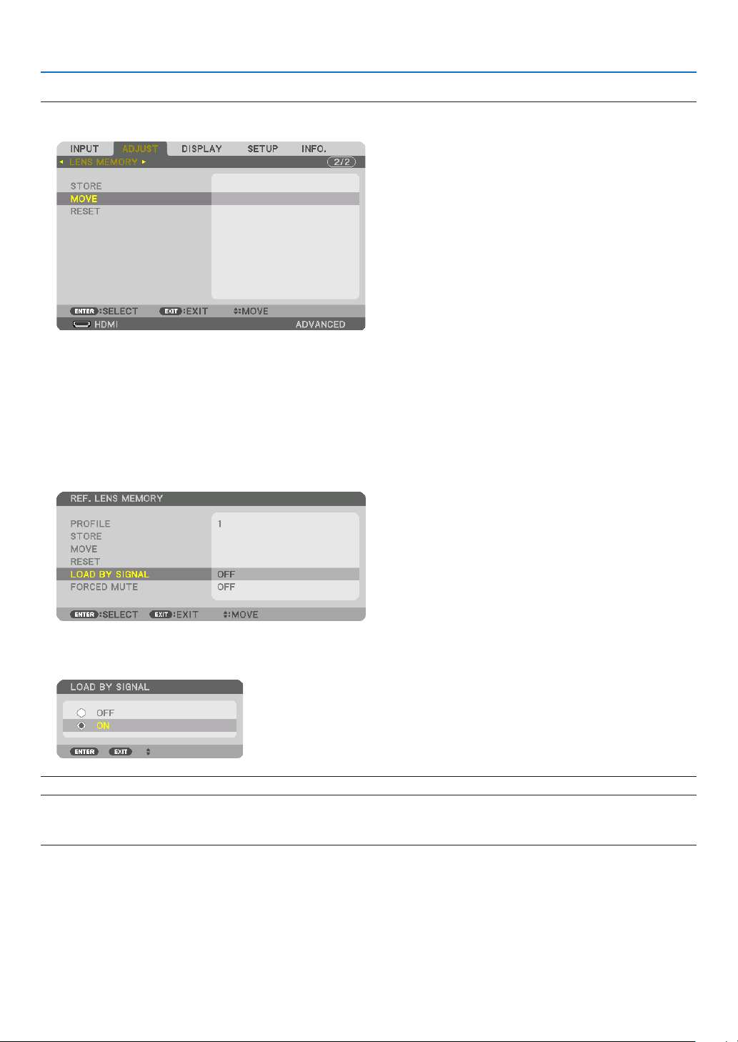
63
3. Convenient Features
TIP:
Tocalluptheadjustedvaluesfrom[LENSMEMORY]:
1. Fromthemenu,select[ADJUST]→[LENSMEMORY]→[MOVE]andpresstheENTERbutton.
Theconrmationscreenwillbedisplayed.
2. Press the ◀buttontoselectand[YES]andpresstheENTERbutton.
Duringprojection,iftheadjustedvaluesforaninputsignalhavebeensaved,thelenswillshift.Ifnot,thelenswill
shiftaccordingtotheadjustedvaluesstoredintheselected[REF.LENSMEMORY][PROFILE]number.
Toautomaticallyapplytheadjustedvaluesatthetimeofsourceselection:
1. Fromthemenu,select[SETUP]→[REF.LENSMEMORY]→[LOADBYSIGNAL]andpresstheENTERbut-
ton.
2. Press the ▼buttontoselectand[ON]andpresstheENTERbutton.
Thiswillmovethelensautomaticallytothepositionatthetimeofsourceselectionaccordingtotheadjustedvalues.
NOTE:TheLensMemoryfunctionmaynotproduceacompletelyalignedimage(duetotolerancesinthelenses)usingtheadjusted
valuesstoredintheprojector.AftercallingupandapplyingtheadjustedvaluesfromtheLensMemoryfunction,nelyadjustthe
lensshift,zoomandfocustoproducethebestpossibleimage.
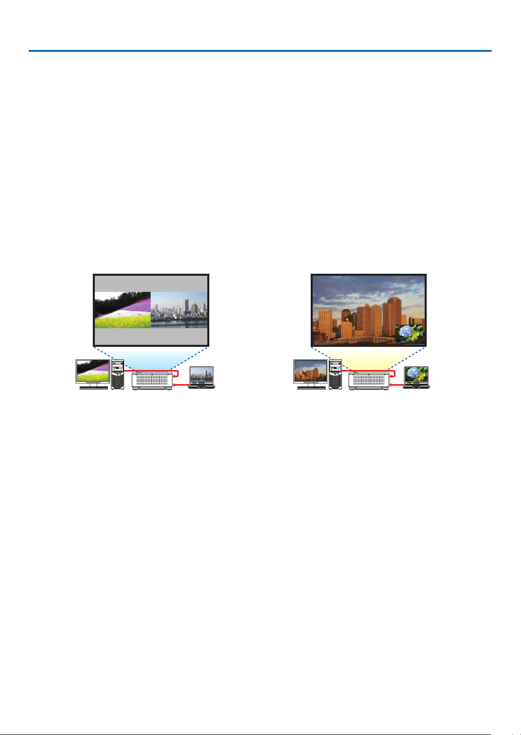
64
4. Multi-Screen Projection
❶ Things that can be done using multi-screen projection
Thisprojectorcanbeusedsinglyorarrangedinmultipleunitsformulti-screenprojection.
Wewillintroduceanexampleusingtwoprojectionscreenshere.
Case 1
Usingasingleprojectortoprojecttwotypesofvideosatthesametime
[PIP/PICTUREBYPICTURE]
Case 2
Usingfourprojectors(resolution:WUXGA)toprojectvideowitharesolutionof2560×1600pixels
[TILING]
Case 1. Using a single projector to project two types of videos [PIP/PICTURE BY
PICTURE]
Connection example and projection image
Inthecaseof[PICTUREBYPICTURE] Inthecaseof[PIP]
On-screen menu operations
Display[DISPLAY]→[PIP/PICTUREBYPICTURE]→[MODE]screenintheon-screenmenuandselect[PIP]or
[PICTUREBYPICTURE].
Fordetails,pleasereferto“4-2DisplayingTwoPicturesattheSameTime”.(→page68)
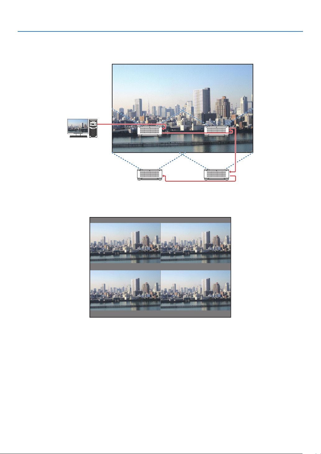
4. Multi-Screen Projection
65
Case 2. Using four projectors (resolution: WUXGA) to project videos with a resolution of
2560 × 1600 pixels [TILING]
Connection example and projection image
On-screen menu operations
1 Foursimilarvideosaredisplayedwhenfourprojectorsareprojected.
Pleaserequestthedealertoadjusttheprojectionpositionofeachprojector.
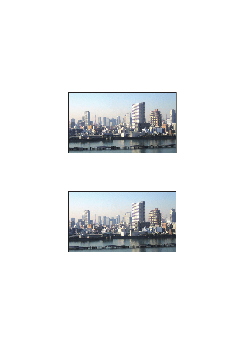
4. Multi-Screen Projection
66
2 Operatetheon-screenmenuusingthefourrespectiveprojectorstodividetheimageintofourportions.
Display[DISPLAY]→[MULTISCREEN]→[PICTURESETTING]Screenintheon-screenmenuandselect[TIL-
ING].
(1)Inthescreenforsettingthenumberofhorizontalunits,select[2UNITS].(numberofunitsinthehorizontaldirec-
tion)
(2)Inthescreenforsettingthenumberofverticalunits,select[2UNITS].(numberofunitsintheverticaldirection)
(3)Inthescreenforsettingthehorizontalorder,select[1stUNIT]or[2ndUNIT].
(lookatthescreens,theoneontheleftisthe[1stUNIT]whiletheoneontherightisthe[2ndUNIT])
(4)Inthescreenforsettingtheverticalorder,selectthe[1stUNIT]orthe[2ndUNIT].
(lookatthescreens,theoneatthetopisthe[1stUNIT]whiletheoneatthebottomisthe[2ndUNIT])
3 Adjustthelensshiftofeachprojectortone-tunetheboundariesofthescreen.
Forfurtherne-tuning,adjustusing[DISPLAY]→[EDGEBLENDING]intheon-screenmenuforeachprojector.
Fordetails,pleasereferto“4-3DisplayingaPictureUsing[EDGEBLENDING]”.
(→page72)
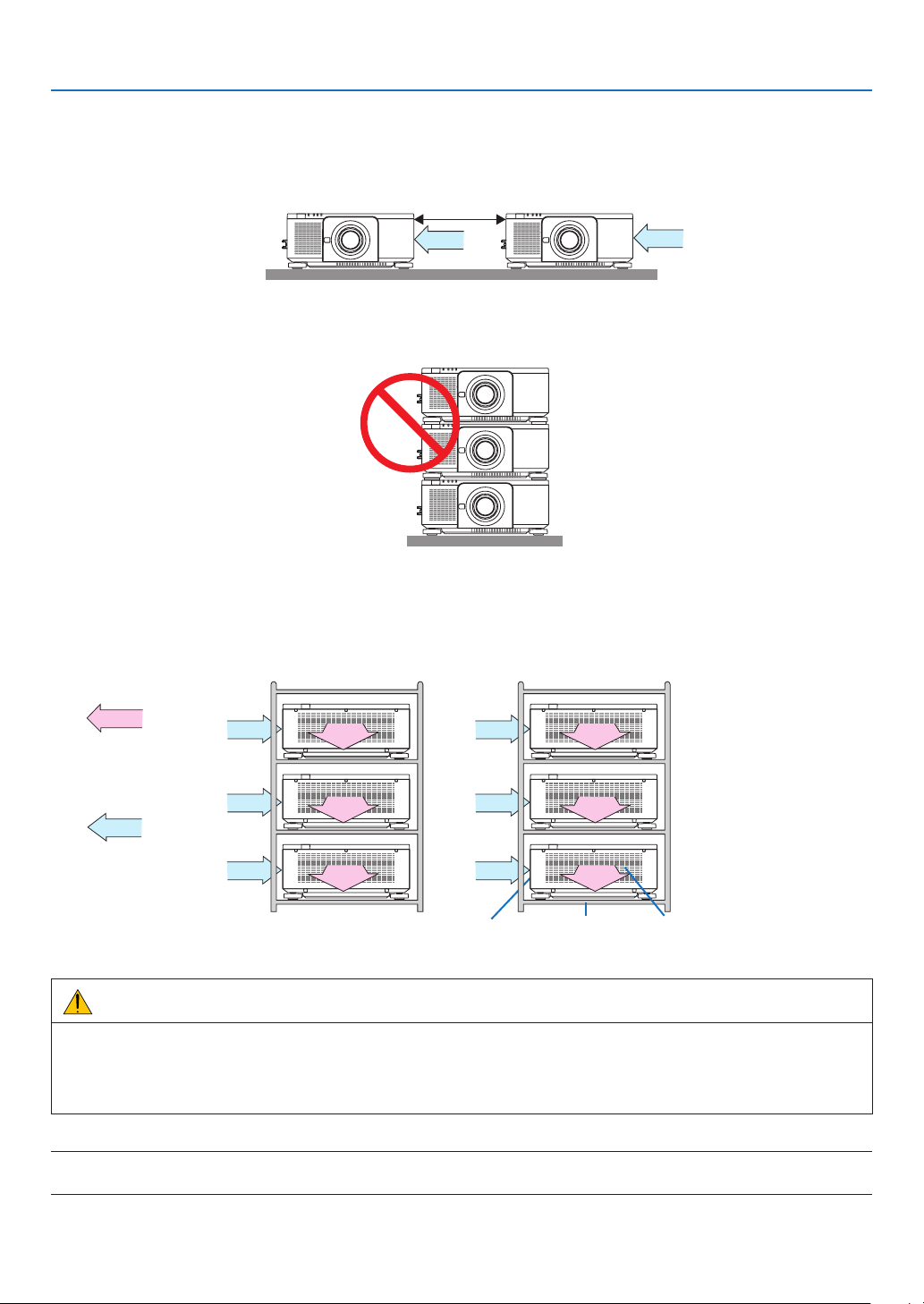
4. Multi-Screen Projection
67
Things to note when installing projectors
• Leave30cmoroverspacebetweeneachprojectorsandbetweentheintakeventandthewallforinstallingprojec-
torssidebyside,sothatairintakeoftheprojectorsarenotobstructed.Whentheairintakeanddischargeoutletare
obstructed,thetemperatureinsidetheprojectorwillriseandthismayresultinamalfunction.
30cmorgreater
• Twoprojectorscanbestackedontopofeachother(STACKsetting).(→page156)Donotattempttodirectlystack
threeormoreprojectors.Whentheprojectorsarepiledupontopofoneanother,theymayfalldown,resultingin
damageandfailure.
• Installationexamplewhenusing3ormoreprojectors
Thefollowinginstallationisrecommendedwheninstallingacombinationof3ormoreprojectorsformulti-screen
projection.
[Installationexample]
ExhaustventIntakevent Cabinet
Airexhaust
Airintake
Back Back
WARNING
Pleaserequestthedealerforspecialinstallationservicessuchaswhenmountingtheprojectortotheceiling.Never
carryouttheinstallationbyyourself.Theprojectormayfalldownandresultininjury.Pleaseuseasturdycabinet
thatcanwithstandtheweightoftheprojectorfortheinstallation.Pleasedonotpileuptheprojectorsdirectlyon
topofoneanother.
NOTE:
• Fortherangeoftheprojectiondistance,pleaserefertotheAppendix“Throwdistanceandscreensize”.(→ page 171)
4. Multi-Screen Projection
68
❷ Displaying Two Pictures at the Same Time
Theprojectorhasafeaturethatallowsyoutoviewtwodifferentsignalssimultaneously.Youhavetwomodes:picture
inpicture(PIP)modeandpicturebypicture(PICTUREBYPICTURE)mode.
Theprojectionvideointherstscreendisplayisknownasthemaindisplaywhiletheprojectionvideothatiscalled
outsubsequentlyisknownasthesub-display.
Selecttheprojectionfunctionunder[DISPLAY]→[PIP/PICTUREBYPICTURE]→[MODE]intheon-screenmenu
(thedefaultfactorysettingwhenshippedisPIP).(→page103)
• Asinglescreenisprojectedwhenpoweristurnedon.
PictureinPicturefunction(PIP)
Asmallsub-displayisdisplayedinsidethemaindisplay.
Thesub-displaycanbesetupandadjustedasfollows.(→page104)
• Selectwhethertodisplaythesub-displayatthetopright,topleft,bottomright
orbottomleftofthescreen(thesizeofthesub-displaycanbeselectedand
thepositioncanbene-tuned)
• Switchthemaindisplaywiththesub-display
Main Display
Sub-Display
Picturebypicturefunction(PICTUREBYPICTURE)
Displaythemaindisplayandsub-displaysidebyside.
Themaindisplayandsub-displaycanbesetupandadjustedasfollows.(→
page104)
• Selectingthedisplayboundary(ratio)ofthemaindisplayandsub-display
• Switchthemaindisplayandsub-display
Main Display Sub-Display
Input terminals that can be used for the main screen and sub-screen.
Themainscreenandsub-screencanprovidethefollowinginputterminals.
• Themaindisplayandsub-displaysupportcomputersignalsuptoWUXGA@60HzRB.
Sub-Display or additional display
HDMI DisplayPort BNC BNC(CV) BNC(Y/C) COMPUTER HDBaseT SLOT
Main Display
HDMI
No
Yes Yes Yes Yes
No No
DisplayPort Yes Yes Yes Yes
BNC Yes Yes
No
No Yes Yes
BNC(CV) Yes Yes Yes Yes Yes
BNC(Y/C) Yes Yes Yes Yes Yes
COMPUTER Yes Yes No Yes Yes No Yes Yes
HDBaseT No Yes Yes Yes Yes No No
SLOT No Yes Yes Yes Yes No No
NOTE:
• Somesignalsmaynotappeardependingontheresolution.
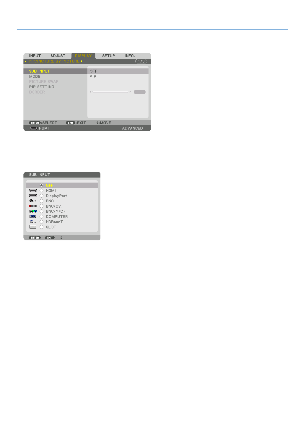
4. Multi-Screen Projection
69
Projecting two screens
1. PresstheMENUbuttontodisplaytheon-screenmenuandselect[DISPLAY]→[PIP/PICTUREBYPICTURE].
Thisdisplaysthe[PIP/PICTUREBYPICTURE]screenintheon-screenmenu.
2. Select[SUBINPUT]usingthe▼/▲ buttons, and press the ENTER button.
Thisdisplaysthe[SUBINPUT]screen.
3. Select the input signal using the ▼/▲ buttons, and press the ENTER button.
The[PIP](PICTUREINPICTURE)or[PICTUREBYPICTURE]screensetupunder[MODE]isprojected.(→page
103)
• Whenthesignalnameisdisplayedingrey,thismeansthatitcannotbeselected.
• ThesignalcanalsobeselectedbypressingthePIP/FREEZEbuttonontheremotecontrol.
4. Press the MENU button.
Theon-screenmenuwilldisappear.
5. Whenreturningtosinglescreen,displaythe[PIP/PICTUREBYPICTUE]screenonemoretimeandselect
[OFF]inthe[SUBINPUT]screenoftheStep3.
TIP:
• Duringdual-screenprojection,iftheselectedinputisnotsupportedbythesub-screen,thesub-screenwillappearasablack
screen.
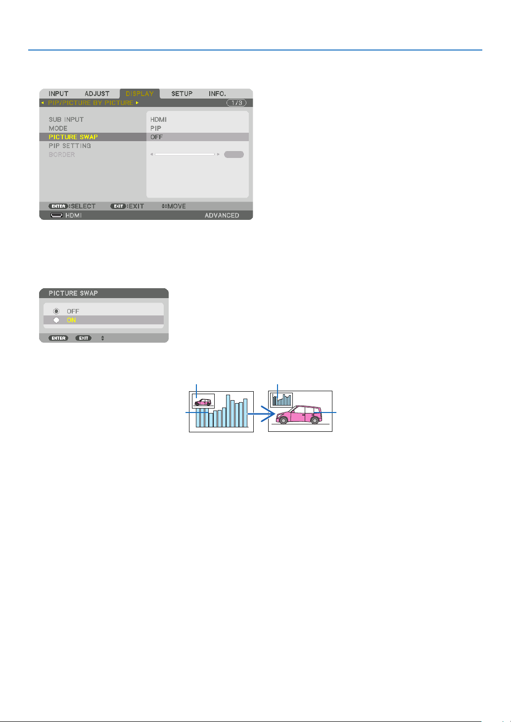
4. Multi-Screen Projection
70
Switching the main display with the sub-display and vice versa
1. PresstheMENUbuttontodisplaytheon-screenmenuandselect[DISPLAY]→[PIP/PICTUREBYPICTURE].
Thisdisplaysthe[PIP/PICTUREBYPICTURE]screenintheon-screenmenu.
2. Select[PICTURESWAP]usingthe▼/▲ buttons and then press the ENTER button.
Displaythescreenforswitchingthedisplaypositions.
3. Select[ON]usingthe▼ button and then press the ENTER button.
Thevideoofthemaindisplaywillswitchwiththatofthesub-display.
Whenturned“OFF” Whenturned“ON”
Sub-displayvideo
Maindisplayvideo Sub-displayvideo
Maindisplayvideo
ThesignaloutputfromtheHDMIOUTterminaldoesnotchangeevenifthedisplaypositionsareswitched.
4. Press the menu button.
Theon-screenmenuwilldisappear.

4. Multi-Screen Projection
71
Restrictions
• Thefollowingoperationsareenabledonlyforthemaindisplay.
• Visualadjustments
• Videomagnication/demaginicationusingthepartialD-ZOOM/ZOOM+/−buttons.
However,magnication/demaginicationisuptotheboundarysetin[PICTUREBYPICTURE].
• TESTPATTERN
• Thefollowingoperationsareenabledforboththemaindisplayandsub-display.Theseoperationscannotbeap-
pliedindividually.
• Momentarydeletionofvideo
• Videopause
• [PIP/PICTUREBYPICTURE]cannotbeusedwhena3Dvideoisbeingdisplayed.
• Whenusingthe[PIP/PICTUREBYPICTURE]function,[CLOSEDCAPTION]and[DYNAMICCONTRAST]can
beused.
• [PIP/PICTUREBYPICTURE]cannotbeusedwhenthesignalinputhasaresolutionof1920×1200ormore.
• TheHDMIOUTterminalhasarepeaterfunction.Theoutputresolutionislimitedbythemaximumresolutionof
theconnectedmonitorandprojector.
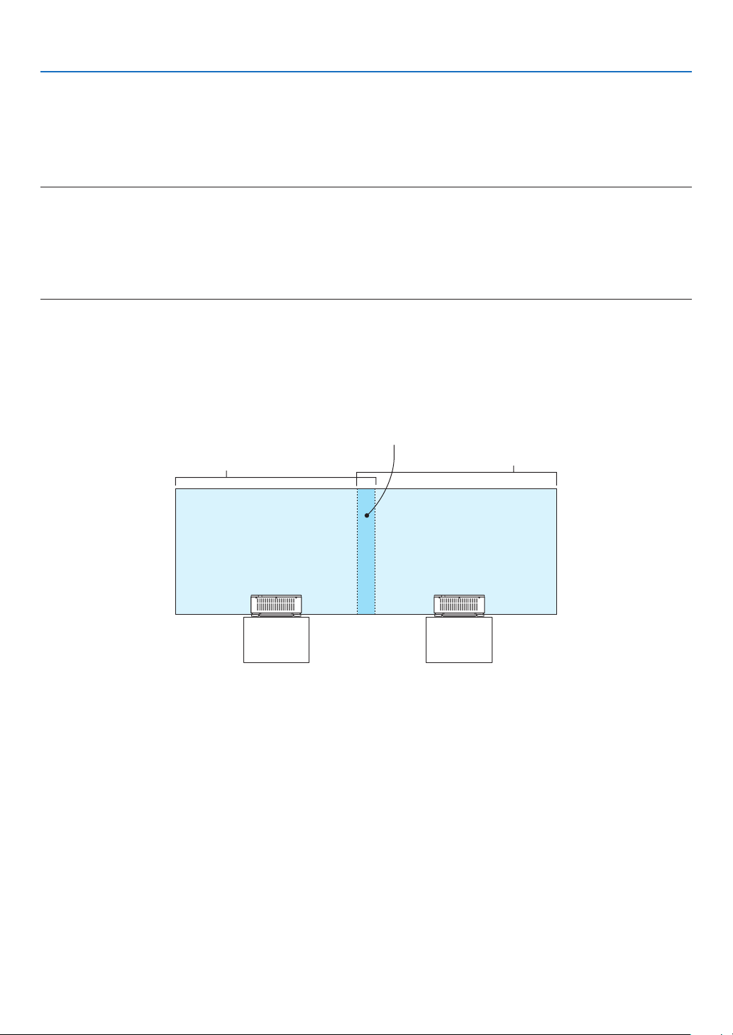
4. Multi-Screen Projection
72
❸ Displaying a Picture Using [EDGE BLENDING]
Ahighresolutionvideocanbeprojectedonanevenbiggerscreenbycombiningmultipleprojectorsontheleft,right,
topandbottom.
Thisprojectorisequippedwithan“EDGEBLENDINGFunction”thatmakestheedges(boundaries)oftheprojection
screenindistinguishable.
NOTE:
• Forprojectorthrowdistances,referto“Throwdistanceandscreensize”onpage171.
• BeforeperformingtheEdgeBlendingfunction,placetheprojectorinthecorrectpositionsothattheimagebecomessquarein
theappropriatesize,andthenmakeopticaladjustments(lensshift,focus,andzoom).
• Adjustthebrightnessofeachprojectorusing[ADJUST]under[LIGHTMODE].Afteradjustingthebrightness,youcankeepthe
setbrightnesslevelbyturningONthe[CONSTANTBRIGHTNESS]mode.Inaddition,use[REF.WHITEBALANCE]toadjustthe
[CONTRAST]and[BRIGHTNESS].
BeforeexplaininguseoftheEdgeBlendingfunction
Thissectionexplainsthecasefor“Example:Placingtwoprojectorssidebyside”.Asshown,theprojectedimageon
theleftisreferredtoas“ProjectorA”andtheprojectedimageontherightisreferredto“ProjectorB”.Unlessotherwise
speciedhereinafter,the“projector”isusedtomeanbothAandB.
Example: Placing two projectors side by side
EdgeBlendingarea
Projectedarea
Projectedarea
ProjectorA ProjectorB
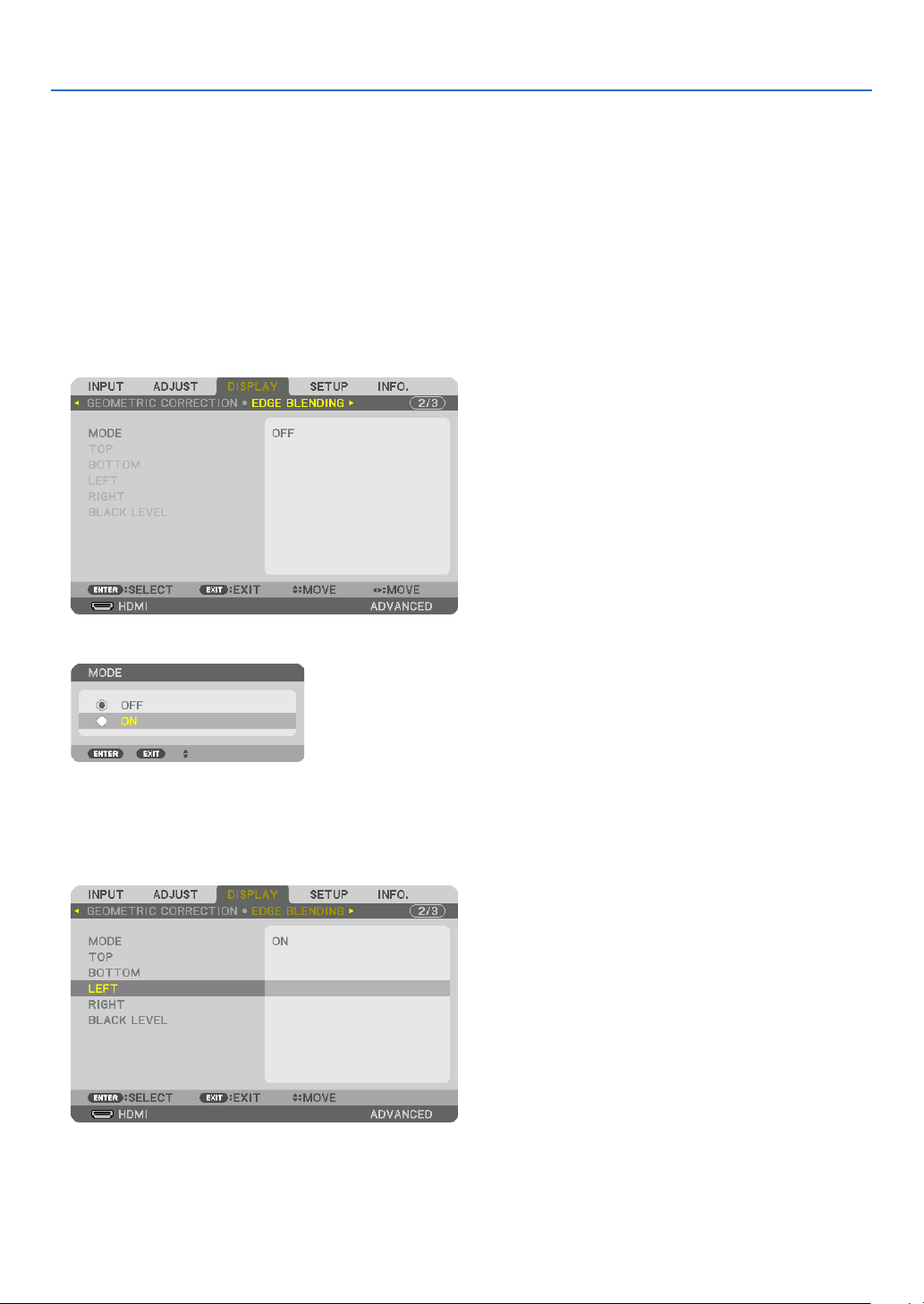
4. Multi-Screen Projection
73
Preparation:
• Turnontheprojectoranddisplayasignal.
• Whenperformingsettingsoradjustmentsusingtheremotecontrol,enablethe[CONTROLID]soasnottoactivate
theotherprojectors.(→page125)
Setting the overlap of projection screens
①
Enable[EDGEBLENDING].
1. Press the MENU button.
Themenuwillbedisplayed.
2. Select[EDGEBLENDING].
The[EDGEBLENDING]screenwillbedisplayed.Alignthecursorwith[MODE]andthenpresstheENTERbutton.
Themodescreenwillbedisplayed.
3. Select[MODE]→[ON]andpresstheENTERbutton.
ThisenablestheEdgeBlendingfunction.Thefollowingmenuitemsareavailable:
[TOP],[BOTTOM],[LEFT],[RIGHT],and[BLACKLEVEL]
4. Select[RIGHT]forProjectorAand[LEFT]forProjectorB.
PresstheENTERbutton.
Thefollowingitemsareavailable:
[CONTROL],[MARKER],[RANGE],and[POSITION]
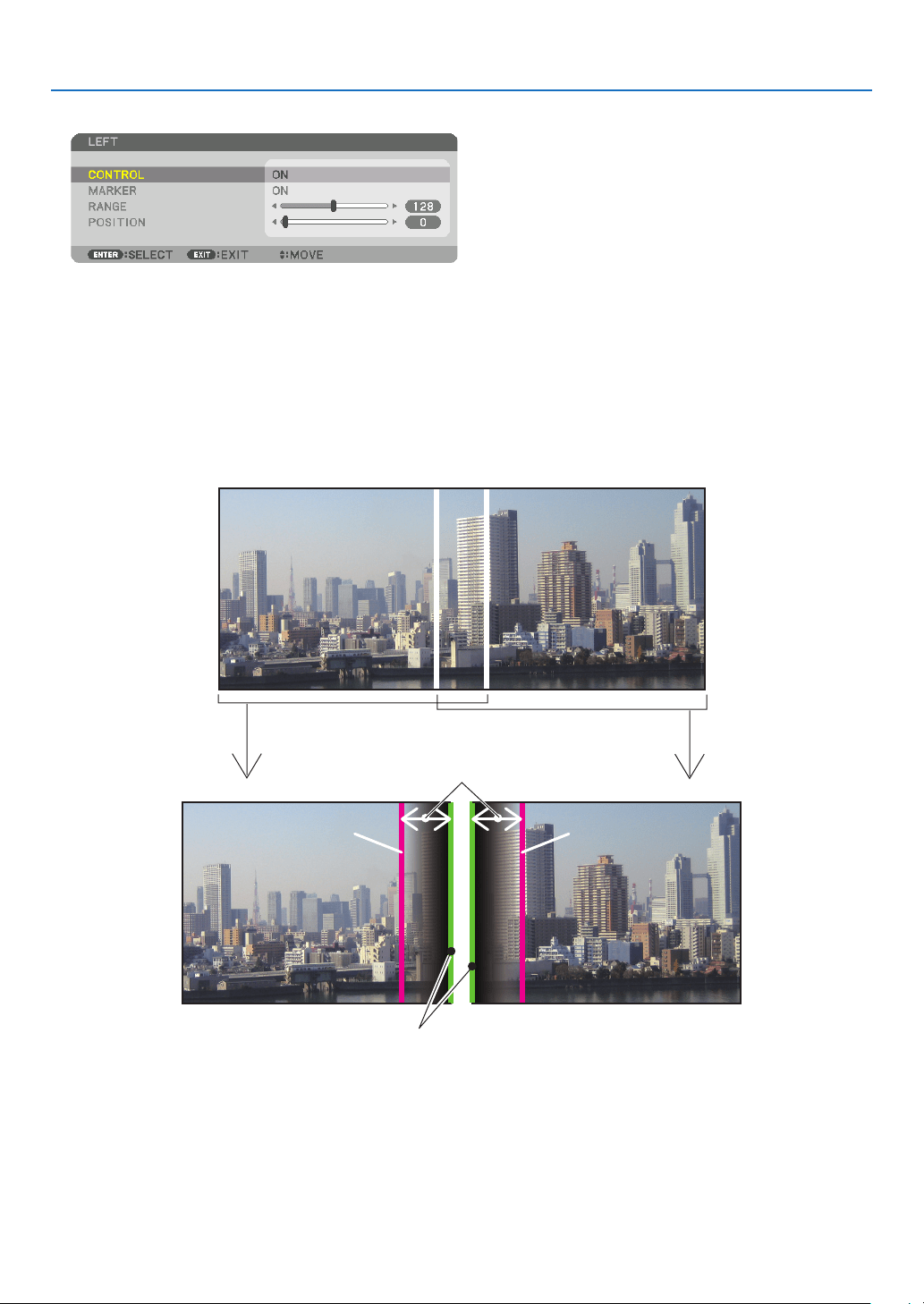
4. Multi-Screen Projection
74
5. Select[CONTROL]→[ON]andpresstheENTERbutton.
Each[TOP],[BOTTOM],[LEFT],[RIGHT],and[BLACKLEVEL]hasitsown[CONTROL],[MARKER],[RANGE],
and[POSITION].
• ForProjectorA,setthe[CONTROL]forthe[TOP],[LEFT]and[BOTTOM]to[OFF].SimilarlyforProjectorB,set
the[CONTROL]forthe[TOP],[RIGHT]and[BOTTOM]to[OFF].
②Adjust[RANGE]and[POSITION]todetermineanareaofoverlappededgesofimages
projected from each projector.
Turningon[MARKER]willdisplaymarkersinmagentaandgreen.
Themagentamarkerisusedfor[RANGE]andgreenonefor[POSITION].
[RANGE]
(Determineanareaofoverlappededgesof
images.)
[POSITION]
(Determinethepositionofoverlappededgesofimages.)
Greenmarker
Turnon[RIGHT]
Magentamarker
Turnon[LEFT]
Magentamarker
* The2screensareseparatedinthediagramforexplanatorypurposes.
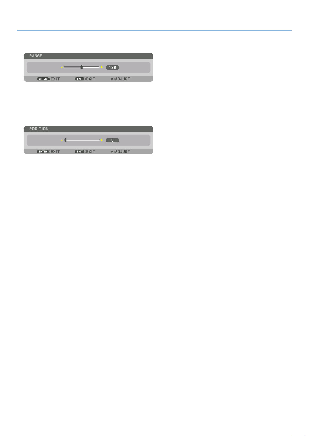
4. Multi-Screen Projection
75
1 Adjust[RANGE].
Usethe◀or▶buttontoadjusttheoverlappedarea.
TIP:
• Adjusttooverlaponeprojector’markerwiththeotherprojector’smarker.
2 Adjust[POSITION].
Usethe◀or▶buttontoalignoneedgewiththeotheredgeofoverlappedimages.
TIP:
• Whendisplayingasignalwithadifferentresolution,performtheEdgeBlendingfunctionfromthestart.
• Settingof[MARKER]willnotbesavedandreturnto[OFF]whentheprojectoristurnedoff.
• Todisplayorhidethemarkerwhiletheprojectorisrunning,turnonoroff[MARKER]fromthemenu.
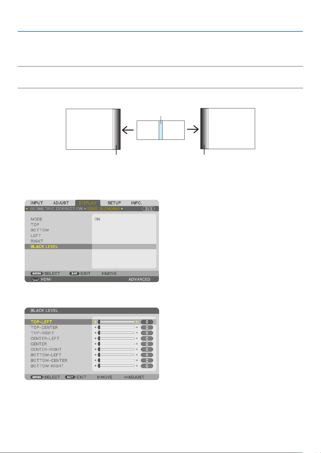
4. Multi-Screen Projection
76
Black Level Adjustment
Thisadjuststheblackleveloftheoverlappingareaandthenon-overlappingareaofthemulti-screen(EDGEBLENDING).
Adjustthebrightnesslevelifyoufeelthedifferenceistoolarge.
NOTE:
Thisfunctionisenabledonlywhen[MODE]isturnedon.
Adjustableareavariesdependingonwhatcombinationof[TOP],[BOTTOM],[LEFT]and[RIGHT]areturnedon.
Example:AdjustingtheBlackLevelwhenplacingtwoprojectorssidebyside
Widthofoverlap
Adjust[CENTER] Adjust[CENTER]
ProjectorA’s
image
ProjectorB’s
image
Adjust[CENTER-RIGHT] Adjust[CENTER-LEFT]
1. Turnon[MODE]
2. Select[BLACKLEVEL]andpresstheENTERbutton.
Thescreenwillswitchtotheblackleveladjustmentscreen.
3. Use the ▼ or ▲ button to select an item and use the ◀ or ▶ to adjust the black level.
Dothisfortheotherprojectorifnecessary.
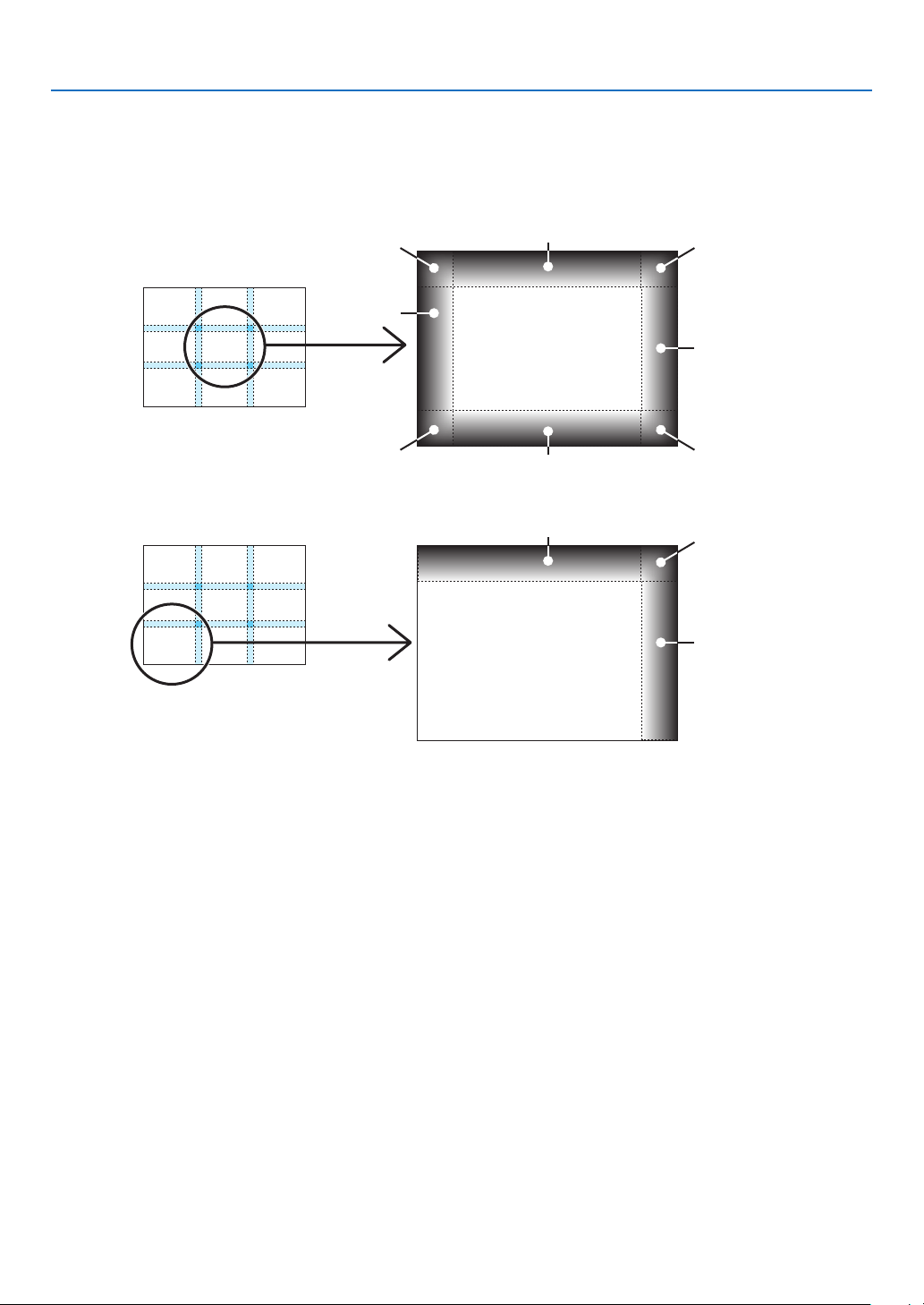
4. Multi-Screen Projection
77
9-segmentedportionsforBlackLeveladjustment
Thecenterprojector
Thisfunctionadjuststhebrightnesslevelof9-segmentedportionsforthecenterprojectorand4-segmentedportions
fortheleftbottomprojectorasshownbelow.
TOP-LEFT
BOTTOM-LEFT
CENTER-
LEFT
TOP-RIGHT
CENTER-RIGHT
BOTTOM-RIGHT
TOP-CENTER
CENTER
CENTER
BOTTOM-CENTER
TOP-RIGHT
CENTER-RIGHT
TOP-CENTER
TIP:
• Thenumberofblackleveldivisionscreens(maximumofninedivisions)changesdependingonthenumberofedgeblending
positionsselected(top,bottom,right,left).Inaddition,whenthetop/bottomandleft/rightendsareselected,thecornerdivision
screen appears.
• Theedgeblendingwidthisthewidthsetintherangeandthecornerisformedbytheintersectingareaofthetop/bottomends
orleft/rightends.
• The[BLACKLEVEL]canbeadjustedtomakeitbrighteronly.
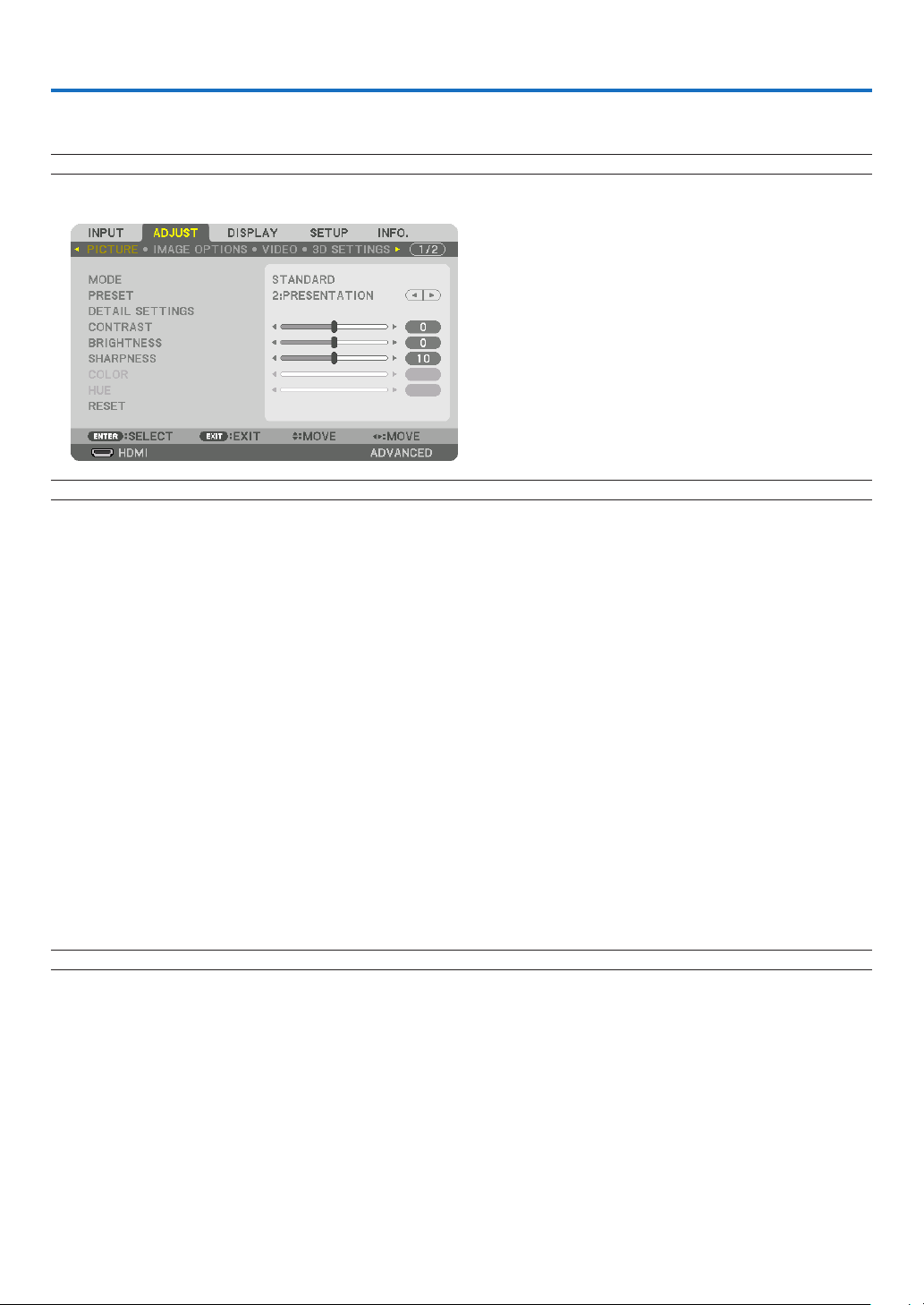
78
5. Using On-Screen Menu
❶ Using the Menus
NOTE:Theon-screenmenumaynotbedisplayedcorrectlydependingoninputsignalandtheprojectorsetting.
1. Press the MENU button on the remote control or the projector cabinet to display the menu.
NOTE:Thecommandssuchas ENTER,EXIT,▲▼, ◀▶inthebottomshowavailablebuttonsforyouroperation.
2. Press the ◀▶ buttons on the remote control or the projector cabinet to display the submenu.
3. PresstheENTERbuttonontheremotecontrolortheprojectorcabinettohighlightthetopitemortherst
tab.
4. Use the ▲▼ buttons on the remote control or the projector cabinet to select the item you want to adjust or
set.
You can use the ◀▶ buttons on the remote control or the projector cabinet to select the tab you want.
5. Press the ENTER button on the remote control or the projector cabinet to display the submenu window.
6. Adjustthelevelorturntheselecteditemonoroffbyusingthe▲▼◀▶ buttons on the remote control or
the projector cabinet.
Changesarestoreduntiladjustedagain.
7. Repeat steps 2-6 to adjust an additional item, or press the EXIT button on the remote control or the projec-
tor cabinet to quit the menu display.
NOTE:Whenamenuormessageisdisplayed,severallinesofinformationmaybelost,dependingonthesignalorsettings.
8. Press the MENU button to close the menu.
To return to the previous menu, press the EXIT button.
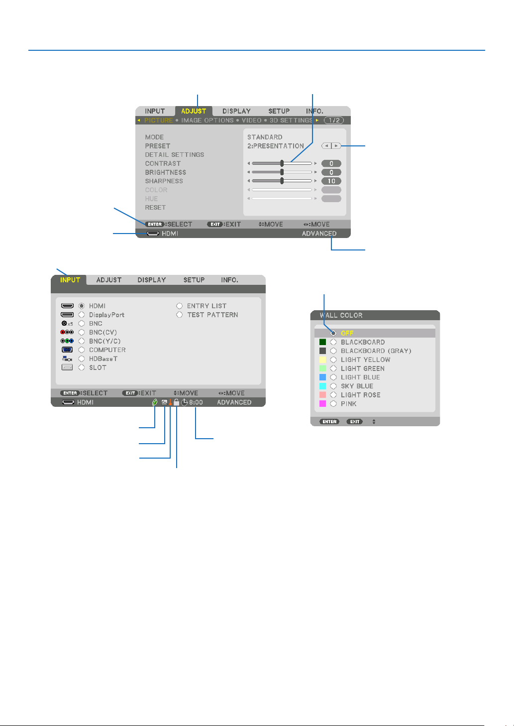
79
5. Using On-Screen Menu
❷
Menu Elements
Slidebar
Solidtriangle
Menumode
Tab
Radiobutton
HIGHsymbol
LIGHTMODEsymbol
Menuwindowsordialogboxestypicallyhavethefollowingelements:
Highlight ����������������������������� Indicates the selected menu or item�
Solid triangle ����������������������Indicates further choices are available� A highlighted triangle indicates the item is active�
Tab ��������������������������������������Indicates a group of features in a dialog box� Selecting on any tab brings its page to the front�
Radio button ����������������������� Use this round button to select an option in a dialog box�
Source ��������������������������������Indicates the currently selected source�
Menu mode ������������������������Indicates the current menu mode: BASIC or ADVANCED�
Off Timer remaining time ���� Indicates the remaining countdown time when the [OFF TIMER] is preset�
Slide bar �����������������������������Indicates settings or the direction of adjustment�
LIGHT MODE symbol ����������Indicates [LIGHT MODE] is set�
Key Lock symbol ����������������Indicates the [CONTROL PANEL LOCK] is enabled�
Thermometer symbol ���������Indicates the [LIGHT MODE] is forcibly set to [ECO] mode because the internal temperature is too
high�
HIGH symbol ����������������������Indicates the [FAN MODE] is set to [HIGH] mode�
Source
Availablebuttons
Thermometersymbol
KeyLocksymbol
OffTimerremaining
time
Highlight
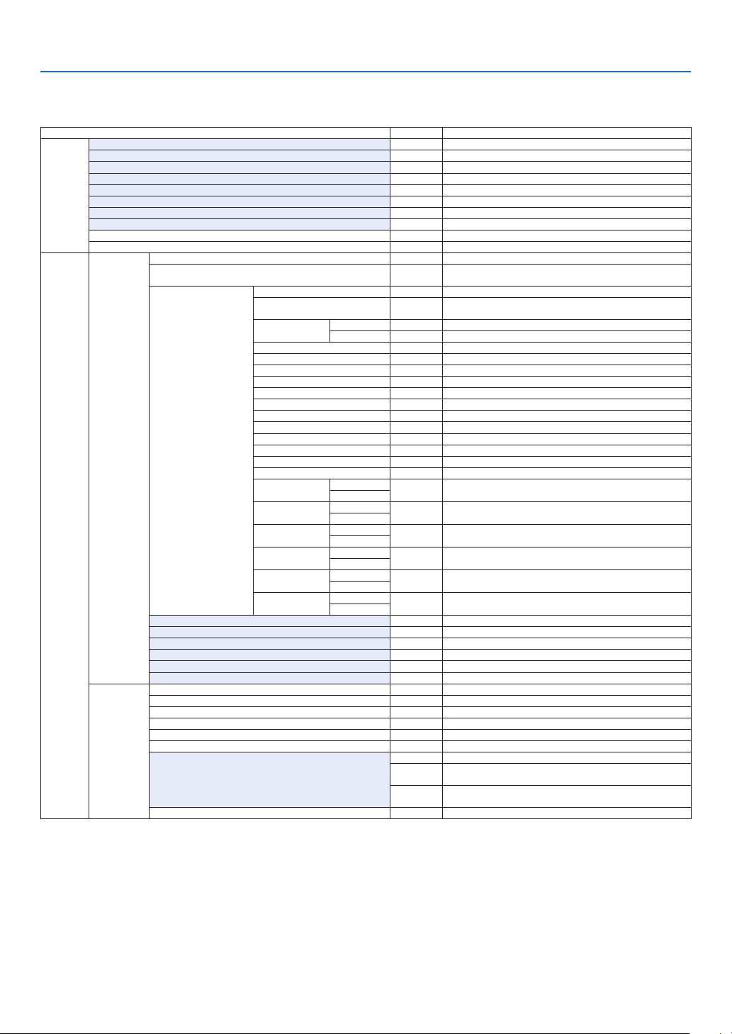
80
5. Using On-Screen Menu
* Theasterisk(*)indicatesthatthedefaultsettingvariesdependingonthesignal.
*1 The[GAMMACORRECTION]itemisavailablewhenanitemotherthan[DICOMSIM.]isselectedfor[REFERENCE].
*2 The[SCREENSIZE]itemisavailablewhen[DICOMSIM.]isselectedfor[REFERENCE].
*3 When[PRESENTATION]or[HIGH-BRIGHT]isselectedin[REFERENCE],the[COLORTEMPERATURE]isnotavailable.
*4 The[INPUTRESOLLUTION]itemisavailablewheneitherCOMPUTERorBNCsignalisselectedastheinputterminal.
•Basicmenuitemsareindicatedbyshadedarea.
❸ List of Menu Items
Somemenuitemsarenotavailabledependingontheinputsource.
Menu Item Default Options
INPUT
HDMI *
DisplayPort *
BNC *
BNC(CV) *
BNC(Y/C) *
COMPUTER *
HDBaseT
SLOT
ENTRY LIST
TEST PATTERN
ADJUST
PICTURE
MODE STANDARD STANDARD, PROFESSIONAL
PRESET *
HIGH-BRIGHT, PRESENTATION, VIDEO, MOVIE, GRAPHIC, sRGB,
DICOM SIM�, EDGE BLENDING
DETAIL SETTINGS
GENERAL
REFERENCE *
HIGH-BRIGHT, PRESENTATION, VIDEO, MOVIE, GRAPHIC, sRGB,
DICOM SIM�, EDGE BLENDING
GAMMA
CORRECTION*
1
SELECT DYNAMIC, NATURAL, BLACK DETAIL
REFERENCE
SCREEN SIZE*
2
* LARGE, MEDIUM, SMALL
COLOR TEMPERATURE*
3
*
DYNAMIC CONTRAST * OFF, ON
Brilliant Color * OFF, MEDIUM, HIGH
WHITE BALANCE
CONTRAST R 0
CONTRAST G 0
CONTRAST B 0
BRIGHTNESS R 0
BRIGHTNESS G 0
BRIGHTNESS B 0
COLOR CORRECTION
RED
HUE
0
SATURATION
GREEN
HUE
0
SATURATION
BLUE
HUE
0
SATURATION
YELLOW
HUE
0
SATURATION
MAGENTA
HUE
0
SATURATION
CYAN
HUE
0
SATURATION
CONTRAST 0
BRIGHTNESS 0
SHARPNESS 0
COLOR 0
HUE 0
RESET
IMAGE
OPTIONS
CLOCK *
PHASE *
HORIZONTAL *
VERTICAL *
BLANKING * TOP, BOTTOM, LEFT, RIGHT
OVERSCAN AUTO AUTO, 0[%], 5[%], 10[%]
ASPECT RATIO
AUTO (COMPUTER) AUTO, 4:3, 5:4, 16:9, 15:9, 16:10, FULL, NATIVE
AUTO
(COMPONENT/VIDEO/S-VIDEO) AUTO, 4:3, LETTERBOX, WIDE
SCREEN, ZOOM
AUTO
(COMPONENT/VIDEO/S-VIDEO) AUTO, 4:3 WINDOW, LETTERBOX,
WIDE SCREEN, FULL
INPUT RESOLUTION*
4
* –

81
5. Using On-Screen Menu
Menu Item Default Options
ADJUST
VIDEO
NOISE REDUCTION
RANDOM NR OFF OFF, LOW, MEDIUM, HIGH
MOSQUITO NR OFF OFF, LOW, MEDIUM, HIGH
BLOCK NR OFF OFF, LOW
DEINTERLACE NORMAL NORMAL, MOVIE, STILL
CONTRAST
ENHANCEMENT
MODE AUTO OFF, AUTO, NORMAL
GAIN
SIGNAL TYPE AUTO AUTO, RGB, COMPONENT
VIDEO LEVEL AUTO AUTO, NORMAL, ENHANCED, SUPER WHITE
3D SETTINGS
FORMAT AUTO
AUTO, OFF(2D), FRAME PACKING, SIDE BY SIDE(HALF), SIDE
BY SIDE(FULL), TOP AND BOTTOM, FRAME ALTERNATIVE, LINE
ALTERNATIVE
L/R INVERT OFF OFF, ON
LENS
MEMORY
STORE
MOVE
RESET
DISPLAY
PIP/PICTURE
BY PICTURE
SUB INPUT
OFF, HDMI, DisplayPort, BNC, BNC(CV), BNC(Y/C), COMPUTER,
HDBaseT, SLOT
MODE PIP PIP, PICTURE BY PICTURE
PICTURE SWAP OFF OFF, ON
PIP SETTING
START POSITION TOP-LEFT TOP-LEFT, TOP-RIGHT, BOTTOM-LEFT, BOTTOM-RIGHT
HORIZONTAL POSITION
VERTICAL POSITION
SIZE MEDIUM LARGE, MEDIUM, SMALL
BORDER
GEOMETRIC
CORRECTION
KEYSTONE
HORIZONTAL
VERTICAL
TILT
THROW RATIO
CORNERSTONE
TOP-LEFT, TOP, TOP-RIGHT, LEFT, RIGHT, BOTTOM-LEFT,
BOTTOM, BOTTOM-RIGHT
HORIZONTAL CORNER
TOP-LEFT, TOP, TOP-RIGHT, LEFT, RIGHT, BOTTOM-LEFT,
BOTTOM, BOTTOM-RIGHT
VERTICAL CORNER
TOP-LEFT, TOP, TOP-RIGHT, LEFT, RIGHT, BOTTOM-LEFT,
BOTTOM, BOTTOM-RIGHT
PINCUSHION
TOP
BOTTOM
LEFT
RIGHT
PC TOOL OFF OFF, 1, 2, 3
RESET
EDGE
BLENDING
MODE OFF OFF, ON
TOP
CONTROL ON OFF, ON
MARKER ON OFF, ON
RANGE
POSITION
BOTTOM
CONTROL ON OFF, ON
MARKER ON OFF, ON
RANGE
POSITION
LEFT
CONTROL ON OFF, ON
MARKER ON OFF, ON
RANGE
POSITION
RIGHT
CONTROL ON OFF, ON
MARKER ON OFF, ON
RANGE
POSITION
BLACK LEVEL
TOP-LEFT
TOP-CENTER
TOP-RIGHT
CENTER-LEFT
CENTER
CENTER-RIGHT
BOTTOM-LEFT
BOTTOM-CENTER
BOTTOM-RIGHT
82
5. Using On-Screen Menu
Menu Item Default Options
DISPLAY
MULTI
SCREEN
WHITE BALANCE
MODE OFF OFF, ON
CONTRAST W
CONTRAST R
CONTRAST G
CONTRAST B
BRIGHTNESS W
BRIGHTNESS R
BRIGHTNESS G
BRIGHTNESS B
PICTURE SETTING
MODE OFF OFF, ZOOM, TILING
ZOOM
HORIZONTAL ZOOM
VERTICAL ZOOM
HORIZONTAL POSITION
VERTICAL POSITION
TILING
WIDTH 1 UNIT, 2 UNITS, 3 UNITS, 4 UNITS
HEIGHT 1 UNIT, 2 UNITS, 3 UNITS, 4 UNITS
HORIZONTAL POSITION 1st UNIT, 2nd UNIT, 3rd UNIT, 4th UNIT
VERTICAL POSITION 1st UNIT, 2nd UNIT, 3rd UNIT, 4th UNIT
SETUP
MENU
LANGUAGE ENGLISH
ENGLISH, DEUTSCH, FRANÇAIS, ITALIANO, ESPAÑOL, SVENSKA,
日本語
DANSK, PORTUGUÊS, ČEŠTINA, MAGYAR, POLSKI,
NEDERLANDS, SUOMI
NORSK, TÜRKÇE, РУССКИЙ,
, Ελληνικά, 中文, 한국어
ROMÂNĂ, HRVATSKA, БЪЛГАРСКИ, INDONESIA, , ไทย,
, 繁體中文
COLOR SELECT COLOR COLOR, MONOCHROME
INPUT DISPLAY ON OFF, ON
MESSAGE DISPLAY ON OFF, ON
ID DISPLAY ON OFF, ON
3D CAUTION MESSAGE ON OFF, ON
DISPLAY TIME
AUTO 45
SEC
MANUAL, AUTO 5 SEC, AUTO 15 SEC, AUTO 45 SEC
INSTALLA-
TION(1)
ORIENTATION AUTO
AUTO, DESKTOP FRONT, CEILING REAR, DESKTOP REAR,
CEILING FRONT
SCREEN TYPE FREE FREE, 4:3 SCREEN, 16:9 SCREEN, 16:10 SCREEN
WALL COLOR OFF
OFF, BLACKBOARD, BLACKBOARD (GRAY), LIGHT YELLOW, LIGHT
GREEN, LIGHT BLUE, SKY BLUE, LIGHT ROSE, PINK
FAN MODE AUTO AUTO, HIGH
LIGHT MODE
LIGHT MODE NORMAL NORMAL, ECO1, ECO2
CONSTANT BRIGHTNESS OFF OFF, ON
ADJUST 20–100%
REF� WHITE BALANCE
CONTRAST R
CONTRAST G
CONTRAST B
BRIGHTNESS R
BRIGHTNESS G
BRIGHTNESS B
3D GLASSES DLP® Link DLP® Link, OTHERS
INSTALLA-
TION(2)
SHUTTER SETTINGS
POWER ON SHUTTER OPEN OPEN, CLOSE
PICTURE MUTE SHUTTER OPEN OPEN, CLOSE
FADE IN TIME
0–10 sec�
FADE OUT TIME 0–10 sec�
REF� LENS MEMORY
PROFILE 1 1, 2
STORE
MOVE
RESET
LOAD BY SIGNAL OFF ON, OFF
FORCED MUTE OFF ON, OFF
LENS CALIBRATION
LENS POSITION
HOME
TYPE NP39ML
83
5. Using On-Screen Menu
Menu Item Default Options
SETUP CONTROL
TOOLS
ADMINISTRA-
TOR MODE
MENU MODE ADVANCED ADVANCED, BASIC
NOT SAVE SETTING VALUES OFF OFF, ON
NEW PASSWORD
CONFIRM PASSWORD
PROGRAM
TIMER
ENABLE OFF OFF, ON
SETTINGS
EDIT
ACTIVE OFF, ON
DAY
SUN, MON, TUE, WED, THU, FRI, SAT, MON-FRI, MON-SAT, EVERY
DAY
TIME
FUNCTION POWER, INPUT, LIGHT MODE
ADVANCED
SETTINGS
POWER OFF OFF, ON
INPUT HDMI
HDMI, DisplayPort, BNC, BNC(CV), BNC(Y/C), COMPUTER,
HDBaseT, SLOT
LIGHT MODE NORMAL NORMAL, ECO1, ECO2
REPEAT OFF OFF, ON
DELETE
UP
DOWN
BACK
DATE AND TIME
SETTINGS
TIME
ZONE
SETTIMGS
GMT
-12:00, -11:30, -11:00, -10:30, -10:00, -09:30, -09:00, -08:30,
-08:00, -07:30, -07:00, -06:30, -06:00, -05:30, -05:00, -04:30,
-04:00, -03:30, -03:00, -02:30, -02:00, -01:30, -01:00, -00:30,
00:00, +00:30, +01:00, +01:30, +02:00, +02:30, +03:00, +03:30,
+04:00, +04;30, +05:00, +05:30, +06:00, +06:30, +07:00, +07:30,
+08:00, +08:30, +09:00, +09:30, +10:00, +10:30, +11:00, +11:30,
+12:00, +12:30, +13:00
DATE
AND TIME
SETTINGS
DATE MM/DD/YYYY
TIME HH:MM
INTERNET TIME
SERVER
OFF OFF, ON
IP ADDRESS
UPDATE
SUMMER
TIME
SETTINGS
ENABLE OFF OFF, ON
MON(START) 1, 2, 3, 4, 5, 6, 7, 8, 9, 10, 11, 12
DAY(START)
FIRST, SECOND, THIRD, FOURTH, LAST
SUN, MON, TUE, WED, THU, FRI, SAT
TIME(START)
MON(EXIT) 1, 2, 3, 4, 5, 6, 7, 8, 9, 10, 11, 12
DAY(EXIT)
FIRST WEEK, SECOND WEEK, THIRD WEEK, FOURTH WEEK, LAST
WEEK
SUN, MON, TUE, WED, THU, FRI, SAT
TIME(EXIT)
TIME DIFFERENCE +01:00, +00:30, -00:30, -01:00
MOUSE
(Note) Cannot be used for this device�
CONTROL PANEL LOCK OFF OFF, ON
SECURITY OFF OFF, ON
COMMUNICATION SPEED 38400bps 4800bps, 9600bps, 19200bps, 38400bps, 115200bps
CONTROL ID
CONTROL ID NUMBER 1 1–254
CONTROL ID OFF OFF, ON
REMOTE SENSOR
FRONT/
BACK
FRONT/BACK, FRONT, BACK, HDBase-T
84
5. Using On-Screen Menu
Menu Item Default Options
SETUP
NETWORK
SETTINGS
WIRED LAN
PROFILES DISABLE, PROFILE 1, PROFILE 2
DHCP OFF, ON
IP ADDRESS
192�168�0�10
SUBNET MASK 255�255�255�0
GATEWAY 192�168�0�1
AUTO DNS OFF, ON
DNS CONFIGURATION
RECONNECT
PROJECTOR NAME PROJECTOR NAME PX803UL Series
DOMAIN
HOST NAME necpj
DOMAIN NAME
ALERT MAIL
ALERT MAIL OFF, ON
HOST NAME
DOMAIN NAME
SENDER'S ADDRESS
SMTP SERVER NAME
RECIPIENT'S ADDRESS 1
RECIPIENT'S ADDRESS 2
RECIPIENT'S ADDRESS 3
TEST MAIL
NETWORK SERVICE
HTTP
SERVER
NEW PASSWORD
CONFIRM PASSWORD
PJLink
NEW PASSWORD
CONFIRM PASSWORD
AMX
BEACON
OFF, ON
CRESTRON
ROOMVIEW OFF, ON
CRESTRON
CONTROL (ENABLE,
CONTROLLER IP
ADDRESS, IP ID)
Extron XTP
OFF, ON
SOURCE
OPTIONS
AUTO ADJUST NORMAL OFF, NORMAL, FINE
COLOR SYSTEM
BNC(VIDEO) AUTO
AUTO, NTSC3�58, NTSC4�43, PAL, PAL-M, PAL-N, PAL60, SECAM
BNC(Y/C) AUTO AUTO, NTSC3�58, NTSC4�43, PAL, PAL-M, PAL-N, PAL60, SECAM
DEFAULT INPUT SELECT LAST
LAST, AUTO, HDMI, DisplayPort, BNC, BNC(CV), BNC(Y/C),
COMPUTER, HDBaseT, SLOT
CLOSED CAPTION OFF
OFF, CAPTION1, CAPTION2, CAPTION3, CAPTION4, TEXT1, TEXT2,
TEXT3, TEXT4
BACKGROUND BLUE BLUE, BLACK, LOGO
POWER
OPTIONS
STANDBY MODE NORMAL NORMAL, NETWORK STANDBY
DIRECT POWER ON OFF OFF, ON
AUTO POWER ON SELECT OFF OFF, HDMI, DisplayPort, COMPUTER, HDBaseT, SLOT
AUTO POWER OFF 1:00 OFF, 0:05, 0:10, 0:15, 0:20, 0:30, 1:00
OFF TIMER OFF OFF, 0:30, 1:00, 2:00, 4:00, 8:00, 12:00, 16:00
SLOT POWER
PROJECTOR ON ON OFF, ON
PROJECTOR STANDBY ENABLE DISABLE, ENABLE
RESET
CURRENT SIGNAL
ALL DATA
ALL DATA (INCLUDING ENTRY LIST)

85
5. Using On-Screen Menu
Menu Item Default Options
INFO�
USAGE TIME
LIGHT HOURS USED
TOTAL CARBON SAVINGS
SOURCE(1)
INPUT TERMINAL
RESOLUTION
HORIZONTAL FREQUENCY
VERTICAL FREQUENCY
SYNC TYPE
SYNC POLARITY
SCAN TYPE
SOURCE NAME
ENTRY NO�
SOURCE(2)
SIGNAL TYPE
VIDEO TYPE
BIT DEPTH
VIDEO LEVEL
LINK RATE
LINK LANE
3D FORMAT
SOURCE(3)
INPUT TERMINAL
RESOLUTION
HORIZONTAL FREQUENCY
VERTICAL FREQUENCY
SYNC TYPE
SYNC POLARITY
SCAN TYPE
SOURCE NAME
ENTRY NO�
SOURCE(4)
SIGNAL TYPE
VIDEO TYPE
BIT DEPTH
VIDEO LEVEL
LINK RATE
LINK LANE
3D FORMAT
WIRED LAN
IP ADDRESS
SUBNET MASK
GATEWAY
MAC ADDRESS
VERSION(1)
FIRMWARE
DATA
SUB-CPU
OTHERS
DATE TIME
PROJECTOR NAME
MODEL NO�
SERIAL NUMBER
CONTROL ID (when [CONTROL ID] is set)
HDBaseT
SIGNAL QUALITY
OPERATION MODE
LINK STATUS
HDMI STATUS

86
5. Using On-Screen Menu
❹ Menu Descriptions & Functions [INPUT]
HDMI
ThisprojectsthevideoofthedeviceconnectedtotheHDMIINterminal.
DisplayPort
ThisprojectsthevideoofthedeviceconnectedtotheDisplayPortINterminal.
BNC
Thisprojectsthevideoofthedeviceconnectedtothevideoinputterminal.
(ThisprojectstheanalogRGBsignalorcomponentsignal.)
BNC(CV)
ThisprojectsthevideoofthedeviceconnectedtotheBNC(CV)videoinputterminal.
(Thisprojectsthecompositevideosignal.)
BNC(Y/C)
ThisprojectsthevideoofthedeviceconnectedtotheBNC(Y/C)videoinputterminal.
(ThisprojectstheS-videosignal.)
COMPUTER
ThisprojectsthevideoofthedeviceconnectedtotheCOMPUTERINterminal.
(ThisprojectstheanalogRGBsignalorcomponentsignal.)
HDBaseT
ProjectingtheHDBaseTorWIREDLANsignal.
SLOT
Projectsthepictureviatheoptionalboard(soldseparately)insertedintotheSLOT.
ENTRY LIST
Displaysalistofsignals.Seethefollowingpages.
TEST PATTERN
Closesthemenuandswitchestothetestpatternscreen.
Selectthepatternusingthe◀▶buttons.
87
5. Using On-Screen Menu
Using the Entry List
Whenanysourceadjustmentsaremade,theadjustmentsareautomaticallyregisteredintheEntryList.The(adjust-
mentvaluesof)registeredsignalscanbeloadedfromtheEntryListwhenevernecessary.
Upto100patternscanberegisteredintheEntryList.When100patternshavebeenregisteredintheEntryList,an
errormessageisthendisplayedandnoadditionalpatternscanberegistered.Youshouldthusdelete(adjustment
valuesof)signalsthatarenolongerneeded.
Displaying the Entry list
1. Press the MENU button.
Themenuwillbedisplayed.
2. Press the ◀ or ▶buttontoselect[INPUT].
TheINPUTlistwillbedisplayed.
3. Use the ◀, ▶, ▲, or ▼toselect[ENTRYLIST]andpresstheENTERbutton.
TheENTRYLISTwindowswillbedisplayed.
IftheENTRYLISTwindowisnotdisplayed,switchthemenuto[ADVANCED].
Toswitchthemenubetween[ADVANCED]and[BASIC],select[SETUP]→[CONTROL]→[TOOLS]→[ADMIN-
ISTRATORMODE]→[MENUMODE].(→page119)
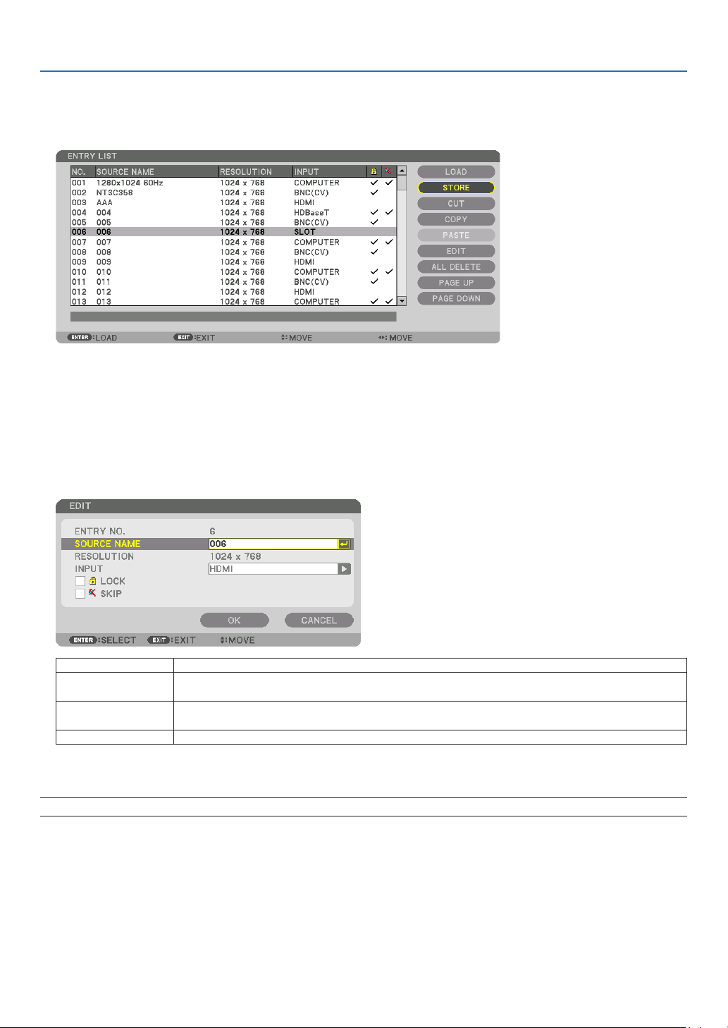
88
5. Using On-Screen Menu
EnteringthecurrentlyprojectedsignalintotheEntryList[STORE]
1. Press the ▲ or ▼ button to select any number.
2. Press the ◀ or ▶buttontoselect[STORE]andpresstheENTERbutton.
CallingupasignalfromtheEntryList[LOAD]
Pressthe▲ or ▼buttontoselectasignalandpresstheENTERbutton.
EditingasignalfromtheEntryList[EDIT]
1. Press the ▲ or ▼ button to select a signal you wish to edit.
2. Press the ◀, ▶, ▲, or ▼buttontoselect[EDIT]andpresstheENTERbutton.
TheEditwindowwillbedisplayed.
SOURCENAME Enterasignalname.Upto18alphanumericcharacterscanbeused.
INPUT Theinputterminalcanbechanged.SwitchingbetweenHDMI/DisplayPort/BNC/BNC(CV)/
BNC(Y/C)/Computer/HDBaseT/SLOTispossible.
LOCK Setsothattheselectedsignalcannotbedeleted when [ALL DELETE] is executed.The
changesmadeafterLOCKexecutioncannotbesaved.
SKIP Setsothattheselectedsignalwillbeskippedduringautosearch.
3. Settheaboveitemsandselect[OK]andpresstheENTERbutton.
NOTE:Theinputterminalcannotbechangedtothecurrentlyprojectedsignal.

89
5. Using On-Screen Menu
CuttingasignalfromtheEntryList[CUT]
1. Press the ▲ or ▼ button to select a signal you wish to delete.
2. Press the ◀, ▶, ▲, or ▼buttontoselect[CUT]andpresstheENTERbutton.
ThesignalwillbedeletedfromtheEntryListandthedeletedsignalwillbedisplayedontheclipboardatthebottom
oftheEntryList.
NOTE:
• Thecurrentlyprojectedsignalcannotbedeleted.
• Whenthelockedsignalisselected,itwillbedisplayedingraywhichindicatesitisnotavailable.
TIP:
• DataontheclipboardcanbepassedontotheEntryList.
• DataontheclipboardwillnotbelostaftertheEntryListisclosed.
CopyingandpastingasignalfromtheEntryList[COPY]/[PASTE]
1. Press the ▲ or ▼ button to select a signal you wish to copy.
2. Press the ◀, ▶, ▲, or ▼buttontoselect[COPY]andpresstheENTERbutton.
ThecopiedsignalwillbedisplayedontheclipboardatthebottomoftheEntryList.
3. Press the ◀ or ▶ button to move to the list.
4. Press the ▲ or ▼ button to select a signal.
5. Press the ◀, ▶, ▲, or ▼buttontoselect[PASTE]andpresstheENTERbutton.
Dataontheclipboardwillbepastedtothesignal.
DeletingallthesignalsfromtheEntryList[ALLDELTE]
1. Press the ◀, ▶, ▲, or ▼buttontoselect[ALLDELETE]andpresstheENTERbutton.
Theconrmationmessagewillbedisplayed.
2. Press the ◀ or ▶buttontoselect[YES]andpresstheENTERbutton.
NOTE: The locked signal cannot be deleted.
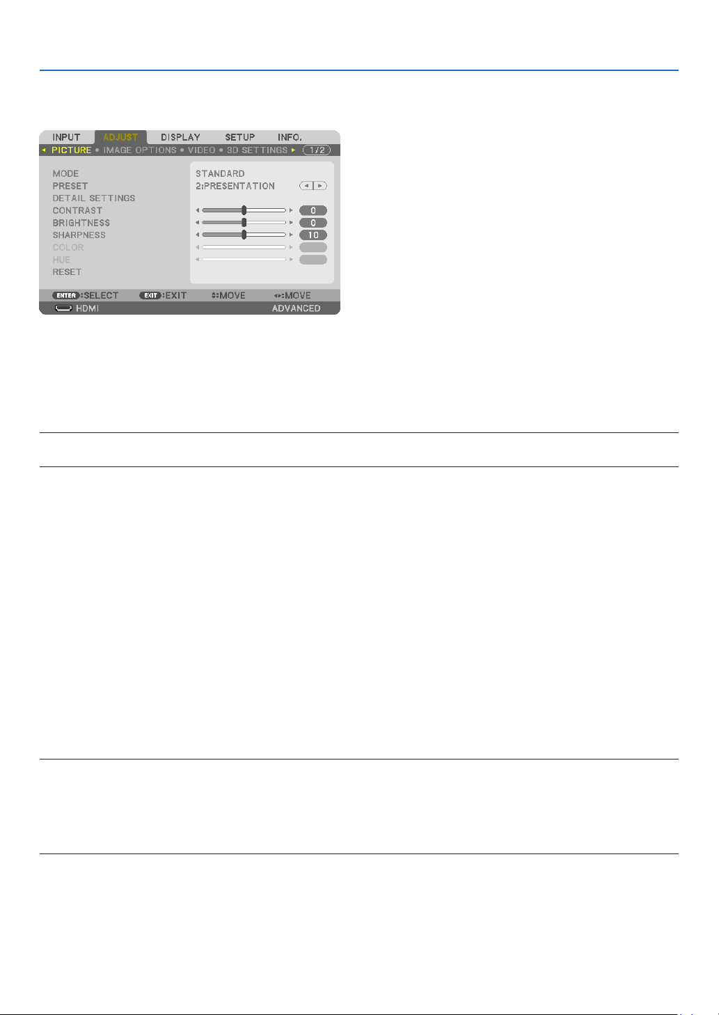
90
5. Using On-Screen Menu
❺ Menu Descriptions & Functions [ADJUST]
[PICTURE]
[MODE]
Thisfunctionallowsyoutodeterminehowtosavesettingsfor[DETAILSETTINGS]of[PRESET]foreachinput.
STANDARD ������������ Saves settings for each item of [PRESET] (Preset 1 through 8)
PROFESSIONAL
����� Saves all the settings of [PICTURE] for each input�
NOTE:
• When[TESTPATTERN]isdisplayed,[MODE]cannotbeselected.
[PRESET]
Thisfunctionallowsyoutoselectoptimizedsettingsforyourprojectedimage.
Youcanadjustneutraltintforyellow,cyanormagenta.
Thereareeightfactorypresetsoptimizedforvarioustypesofimages.Youcanalsouse[DETAILSETTINGS]toset
useradjustablesettingstocustomizeeachgammaorcolor.
Yoursettingscanbestoredin[PRESET1]to[PRESET8].
HIGH-BRIGHT �������� Recommended for use in a brightly lit room�
PRESENTATION ����� Recommended for making a presentation using a PowerPoint file�
VIDEO �������������������� Recommended for typical TV program viewing�
MOVIE ������������������� Recommended for movies�
GRAPHIC ��������������� Recommended for graphics�
sRGB ��������������������� Standard color values
DICOM SIM� ���������� Recommended for DICOM simulation format�
EDGE BLENDING ��� Recommended for edge blending�
NOTE:
• The[DICOMSIM.]optionisfortraining/referenceonlyandshouldnotbeusedforactualdiagnosis.
• DICOMstandsforDigitalImagingandCommunicationsinMedicine.ItisastandarddevelopedbytheAmericanCollegeofRadiol-
ogy(ACR)andtheNationalElectricalManufacturersAssociation(NEMA).
Thestandardspecieshowdigitalimagedatacanbemovedfromsystemtosystem.
• Adjustmentmaynotworkdependingoninputsignal.
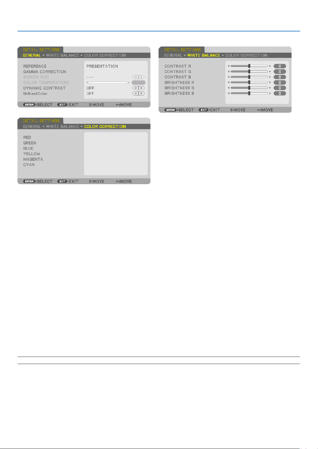
91
5. Using On-Screen Menu
[DETAILSETTINGS]
[GENERAL]
StoringYourCustomizedSettings[REFERENCE]
Thisfunctionallowsyoutostoreyourcustomizedsettingsin[PRESET1]to[PRESET8].
First,selectabasepresetmodefrom[REFERENCE],thenset[GAMMACORRECTION]and[COLORTEMPERATURE].
HIGH-BRIGHT �������� Recommended for use in a brightly lit room�
PRESENTATION ����� Recommended for making a presentation using a PowerPoint file�
VIDEO �������������������� Recommended for typical TV program viewing�
MOVIE ������������������� Recommended for movies�
GRAPHIC ��������������� Recommended for graphics�
sRGB ��������������������� Standard color values�
DICOM SIM� ���������� Recommended for DICOM simulation format�
EDGE BLENDING ��� Recommended for edge blending�
SelectingGammaCorrectionMode[GAMMACORRECTION]
Eachmodein[SELECT]correctscolortoneofprojectedimageandisrecommendedfor:
DYNAMIC �������������� Creates a high-contrast picture�
NATURAL ��������������� Natural reproduction of the picture�
BLACK DETAIL ������� Emphasizes detail in dark areas of the picture�
In[REFERENCE],itadjustscorrectedvalueforprojectedimage.Highervaluemeansdeepercorrection.
NOTE:Thisfunctionisnotavailablewhen[DICOMSIM.]isselectedfor[DETAILSETTINGS].

92
5. Using On-Screen Menu
SelectingScreenSizeforDICOMSIM[SCREENSIZE]
Thisfunctionwillperformgammacorrectionappropriateforthescreensize.
LARGE ������������������� For screen size of 150"
MEDIUM
���������������� For screen size of 100"
SMALL
������������������� For screen size of 50"
NOTE:
• Thisfunctionisavailableonlywhen[DICOMSIM.]isselectedfor[DETAILSETTINGS].
• Correctionvalueischangeddependingonprojectionimages.
AdjustingColorTemperature[COLORTEMPERATURE]
Thisoptionallowsyoutoselectthecolortemperatureofyourchoice.
Avaluebetween5000Kand10500Kcanbesetina500Kunit.
NOTE:
• When[HIGH-BRIGHT]isselectedin[REFERENCE],thisfunctionisnotavailable.
• When[PRESENTATION]isselectedin[REFERENCE],theselectablerangefor[COLORTEMPERATURE]is3levels,0,1,and3.
AdjustingBrightnessandContrast[DYNAMICCONTRAST]
If[ON]isselected,themostoptimalcontrastratioisusedaccordingtothepicture.
NOTE:
• Dependingontheconditions,projectorsettingssuchas[DYNAMICCONTRAST]maynotbeabletobeselected.
[BrilliantColor]
Selectsthebrightnessofthecolorwhite.
Selectingoptionsfrom[MEDIUM]to[HIGH]increasesthebrightnessofthecolorwhite.
NOTE:
• Ifunder[REFERENCE],[HIGH-BRIGHT]or[PRESENTATION]areselected,[BrilliantColor]cannotbechanged.
AdjustingWhiteBalance[WHITEBALANCE]
Thisallowsyoutoadjustthewhitebalance.Contrastforeachcolor(RGB)toadjustthewhitelevelofthescreen;
Brightnessforeachcolor(RGB)isusedtoadjusttheblacklevelofthescreen.
[COLORCORRECTION]
Correctsthecolorforallsignals.
Adjuststhetoneforthecolorsred,green,blue,yellow,magentaandcyan.
RED HUE +Direction Magentadirection
−Direction Yellowdirection
SATURATION +Direction Vivid
−Direction Weak
GREEN HUE
+Direction Yellowdirection
−Direction Cyandirection
SATURATION +Direction Vivid
−Direction Weak
BLUE HUE
+Direction Cyandirection
−Direction Magentadirection
SATURATION +Direction Vivid
−Direction Weak
YELLOW HUE
+Direction Reddirection
−Direction Greendirection
SATURATION +Direction Vivid
−Direction Weak

93
5. Using On-Screen Menu
MAGENTA HUE +Direction Bluedirection
−Direction Reddirection
SATURATION +Direction Vivid
−Direction Weak
CYAN HUE
+Direction Greendirection
−Direction Bluedirection
SATURATION +Direction Vivid
−Direction Weak
[CONTRAST]
Adjuststheintensityoftheimageaccordingtotheincomingsignal.
[BRIGHTNESS]
Adjuststhebrightnesslevelorthebackrasterintensity.
[SHARPNESS]
Controlsthedetailoftheimage.
[COLOR]
Increasesordecreasesthecolorsaturationlevel.
[HUE]
Variesthecolorlevelfrom+/−greento+/−blue.Theredlevelisusedasreference.
Inputsignal CONTRAST BRIGHTNESS SHARPNESS COLOR HUE
RGBsystemof“COMPUTER/
DisplayPort/HDMI/HDBaseT”
Ye s Ye s Ye s No No
COMPONENTsystemof“COMPUTER/
DisplayPort/HDMI/HDBaseT”
Ye s Ye s Ye s Ye s Ye s
CompositeVideo/S-Video Ye s Ye s Ye s Ye s Ye s
Yes=Adjustable,No=Notadjustable
NOTE:
• When[TESTPATTERN]isdisplayed,[CONTRAST],[BRIGHTNESS],[SHARPNESS],[COLOR]and[HUE]cannotbeadjusted.
[RESET]
Thesettingsandadjustmentsfor[PICTURE]willbereturnedtothefactorysettingswiththeexceptionofthefollowing;
Presetnumbersand[REFERENCE]withinthe[PRESET]screen.
Thesettingsandadjustmentsunder[DETAILSETTINGS]withinthe[PRESET]screenthatarenotcurrentlyselected
willnotbereset.
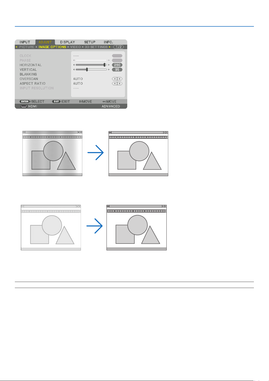
94
5. Using On-Screen Menu
[IMAGE OPTIONS]
AdjustingClockandPhase[CLOCK/PHASE]
ThisallowsyoutomanuallyadjustCLOCKandPHASE.
CLOCK ������������������� Use this item to fine tune the computer image or to remove any vertical banding that might appear� This
function adjusts the clock frequencies that eliminate the horizontal banding in the image�
This adjustment may be necessary when you connect your computer for the first time�
PHASE ������������������� Use this item to adjust the clock phase or to reduce video noise, dot interference or cross talk� (This is
evident when part of your image appears to be shimmering�)
Use [PHASE] only after the [CLOCK] is complete�
NOTE:The[CLOCK]and[PHASE]itemsareavailableforRGBsignalsonly.
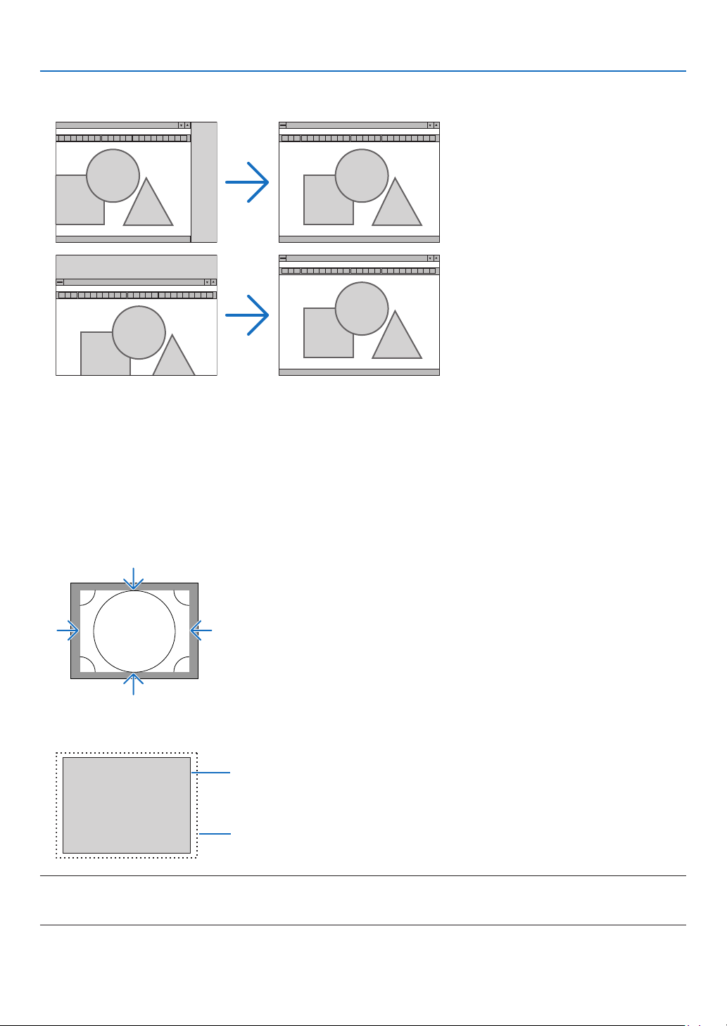
95
5. Using On-Screen Menu
AdjustingHorizontal/VerticalPosition[HORIZONTAL/VERTICAL]
Adjuststheimagelocationhorizontallyandvertically.
• Animagecanbedistortedduringtheadjustmentof[CLOCK]and[PHASE].Thisisnotmalfunction.
• Theadjustmentsfor[CLOCK], [PHASE],[HORIZONTAL],and[VERTICAL]willbestoredinmemoryforthe
currentsignal.Thenexttimeyouprojectthesignalwiththesameresolution,horizontalandverticalfrequency,
itsadjustmentswillbecalledupandapplied.
Todeleteadjustmentsstoredinmemory,fromthemenu,youselect[RESET]→[CURRENTSIGNAL]andreset
theadjustments.
[BLANKING]
Adjuststhedisplayrange(blanking)atthetop,bottom,leftandrightedgesoftheinputsignal.
SelectingOverscanPercentage[OVERSCAN]
Selectoverscanpercentage(Auto,0%,5%and10%)forsignal.
Projectedimage
Overscanedby10%
NOTE:
• The[OVERSCAN]itemisnotavailable:
-when[NATIVE]isselectedfor[ASPECTRATIO].
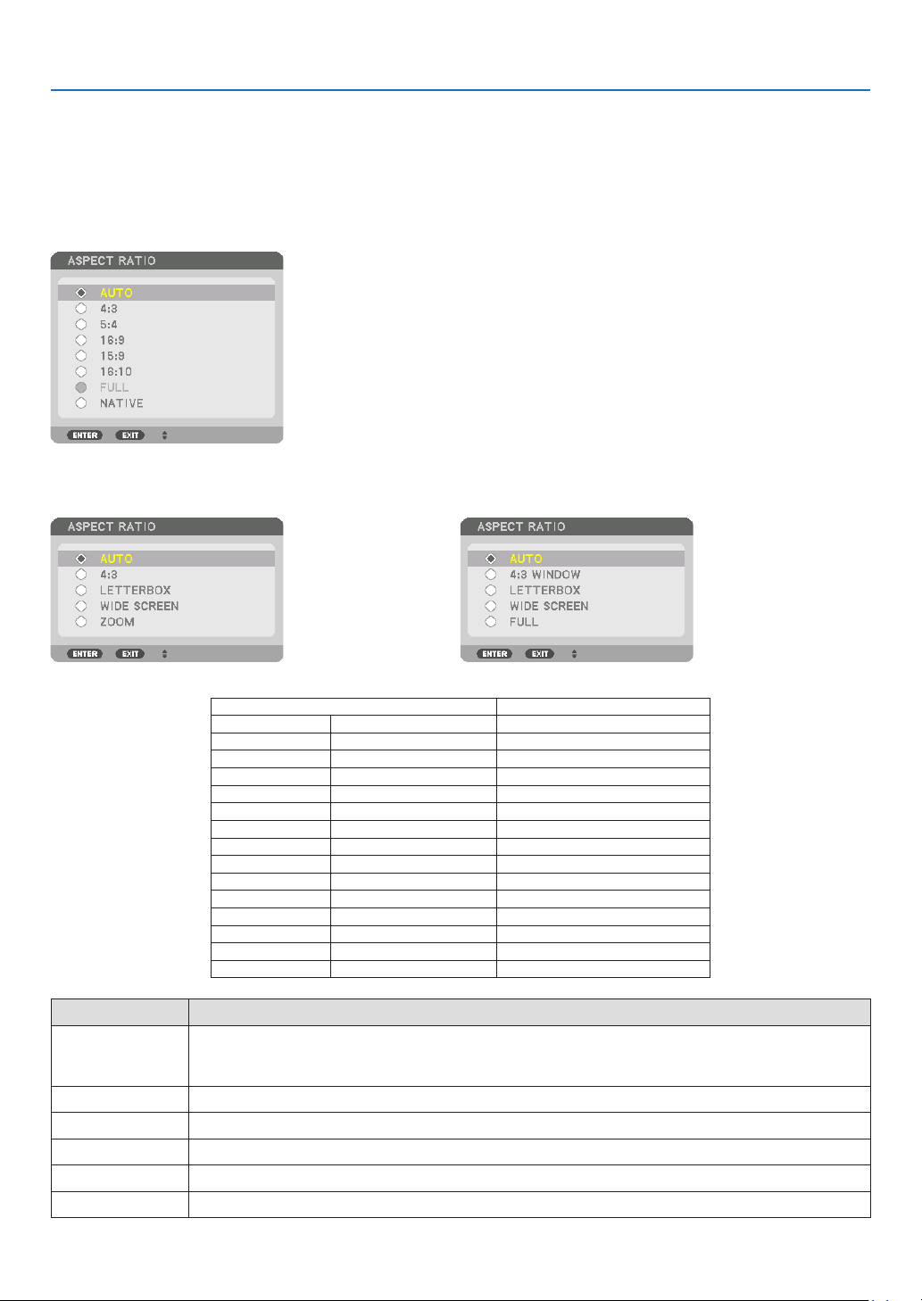
96
5. Using On-Screen Menu
SelectingtheAspectRatio[ASPECTRATIO]
Usethisfunctiontoselectthescreen’svertical:horizontalaspectratio.
Selectthescreentype(4:3screen,16:9screenor16:10screen)inthe[INSTALLATION(1)]beforesettingtheaspect
ratio.(→page115)
Theprojectorautomaticallyidentiesthesignalbeinginputandsetstheoptimumaspectratio.
For Computer signal
ForComponent/Video/S-Videosignals
Whenthescreentypeissetto4:3 Whenthescreentypeissetto16:9or16:10
Resolution AspectRatio
VGA 640×480 4:3
SVGA
800×600 4:3
XGA
1024×768 4:3
WXGA
1280×768 15:9
WXGA
1280×800 16:10
HD(FWXGA)
1366×768 approx.16:9
WXGA+ 1440×900 16:10
SXGA
1280×1024 5:4
SXGA+
1400×1050 4:3
WXGA++
1600×900 16:9
UXGA
1600×1200 4:3
WSXGA+
1680×1050 16:10
FHD(1080P)
1920×1080 16:9
WUXGA
1920×1200 16:10
WQXGA
2560×1600 16:10
Options Function
AUTO
Theprojectorwillautomaticallydeterminetheincomingsignalanddisplayitinitsaspectratio.
Theprojectormayerroneouslydeterminetheaspectratiodependingonitssignal.Ifthisoccurs,select
theappropriateaspectratiofromthefollowing.
4:3 Theimageisdisplayedin4:3aspectratio.
5:4 Theimageisdisplayedin5:4aspectratio
16:9 Theimageisdisplayedin16:9aspectratio
15:9 Theimageisdisplayedin15:9aspectratio
16:10 Theimageisdisplayedin16:10aspectratio
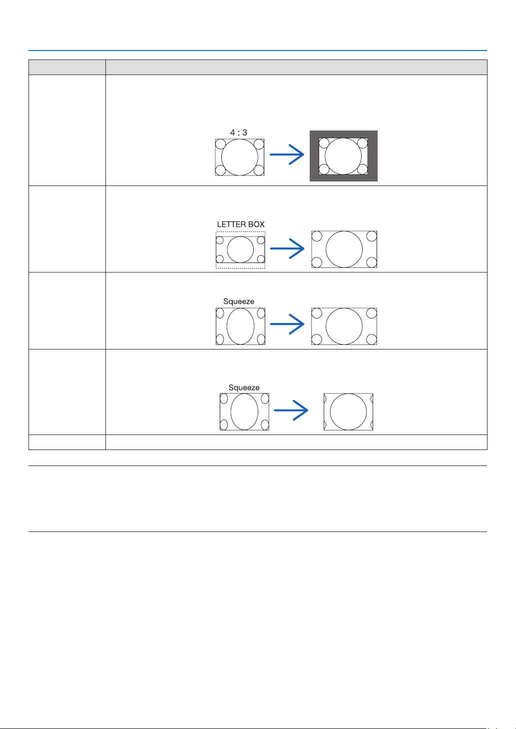
97
5. Using On-Screen Menu
Options Function
NATIVE
Theprojectordisplaysthecurrentimageinitstrueresolutionwhentheincomingcomputersignalhasa
lowerorhigherresolutionthantheprojector’snativeresolution.(→page3)
Whentheincomingcomputersignalhasahigherresolutionthantheprojector'snativeresolution,the
centerofanimagewillbedisplayed.
LETTERBOX Theimageofaletterboxsignal(16:9)isstretchedequallyinthehorizontalandverticaldirectionstotthe
screen.
WIDESCREEN Theimageofasqueezesignal(16:9)isstretchedleftandrightin16:9.
ZOOM Theimageofasqueezesignal(16:9)isstretchedleftandrightin4:3.
Partsofthedisplayedimagearecroppedattheleftandrightedgesandthereforenotvisible.
FULL Projecttofullscreensize.
TIP:
• Imagepositioncanbeadjustedverticallyusing[POSITION]whenthe[16:9],[15:9],or[16:10]aspectratiosareselected.
• Theterm“letterbox”referstoamorelandscape-orientedimagewhencomparedtoa4:3image,whichisthestandardaspect
ratioforavidesource.
Theletterboxsignalhasaspectratioswiththevistasize“1.85:1”orcinemascopesize“2.35:1”formovielm.
• Theterm“squeeze”referstothecompressedimageofwhichaspectratioisconvertedfrom16:9to4:3.
[INPUTRESOLUTION]
Theresolutionisassignedautomaticallywhentheresolutionoftheinputsignalfromthecomputervideoinputterminal
orBNCvideoinputterminal(analogRGB)cannotbedistinguished.

98
5. Using On-Screen Menu
[VIDEO]
UsingNoiseReduction[NOISEREDUCTION]
Whenprojectingavideoimage,youcanusethe[NOISEREDUCTION]functiontoreducethescreennoise(roughness
anddistortion).Thisdeviceisequippedwiththreetypesofnoisereductionfunctions.Selectthefunctionaccordingto
thetypeofnoise.Dependingonthenoiselevel,thenoisereductioneffectcanbesetto[OFF],[LOW],[MEDIUM]or
[HIGH].[NOISEREDUCTION]canbeselectedforSDTV,HDTVsignalandcomponentsignalinput.
RANDOM NR ��������� Reduces flickering random noise in an image�
MOSQUITO NR ������ Reduces mosquito noise that appears around the edges of an image during Blu-ray playback�
BLOCK NR ������������� Reduces block noise or mosaic-like patterns by selecting ON�
SelectingInterlacedProgressiveConversionProcessMode[DEINTERLACE]
Thisfunctionallowsyoutoselectaninterlaced-to-progressiveconversionprocessforvideosignals.
NORMAL ���������������� Automatically distinguishes a moving image from a static image to create a distinct image� Please select
[MOVIE] if there are any obvious jitter and noises�
MOVIE ������������������� Select when projecting moving images� This is suitable for signals with a lot of jitter and noise�
STILL ��������������������� Select when projecting static images� The video will flicker when a moving image is projected�
NOTE:ThisfunctionisnotavailablewithRGBsignals.
[CONTRASTENHANCEMENT]
Usingthecharacteristicsofthehumaneye,apicturequalitywithasenseofcontrastandresolutionisachieved.
OFF ������������������������ Suite vision is switched off�
AUTO ��������������������� Contrast and picture quality are automatically improved using the suite vision function�
NORMAL ���������������� Adjust the gain manually�

99
5. Using On-Screen Menu
[SIGNALTYPE]
SelectionofRGBandcomponentsignals.Normally,thisissetto[AUTO].Pleasechangethesettingifthecolorofthe
imageremainsunnatural.
AUTO ��������������������� Automatically distinguishes RGB and component signals�
RGB ����������������������� Switches to the RGB input�
COMPONENT ��������� Switches to the component signal input�
[VIDEOLEVEL]
SelectionofthevideosignallevelwhenconnectinganexternaldevicetotheHDMIINterminal,DisplayPortinput
terminal,andHDBaseTinputterminaloftheprojector.
AUTO ��������������������� The video level is switched automatically based on the information from the device outputting the signal�
Depending on the connected device, this setting may not be made properly� In this case, switch to [NORMAL”
or “ENHANCED” from the menu and view with the optimum setting�
NORMAL ���������������� This disables the enhanced mode�
ENHANCED ������������ This improves the image’s contrast, expressing the dark and light sections more dynamically�
SUPER WHITE ������� The video contrast is improved and the dark areas appear more dynamic�

100
5. Using On-Screen Menu
[3D SETTINGS]
Pleasereferto“3-9Projecting3Dvideos”(→page48)fortheoperation.
FORMAT
Selectthe3Dvideoformat(recording/transmissionformat).Selecttomatchthe3Dbroadcastand3Dmedia.Nor-
mally,[AUTO]isselected.Pleaseselectthe3Dinputsignalformatwhenthe3Ddetectionsignaloftheformatcannot
bedistinguished.
L/RINVERT
Invertthedisplayorderoftheleftandrightvideos.
Select[ON]ifyoufeeluncomfortablewiththe3Ddisplaywhen[OFF]isselected.
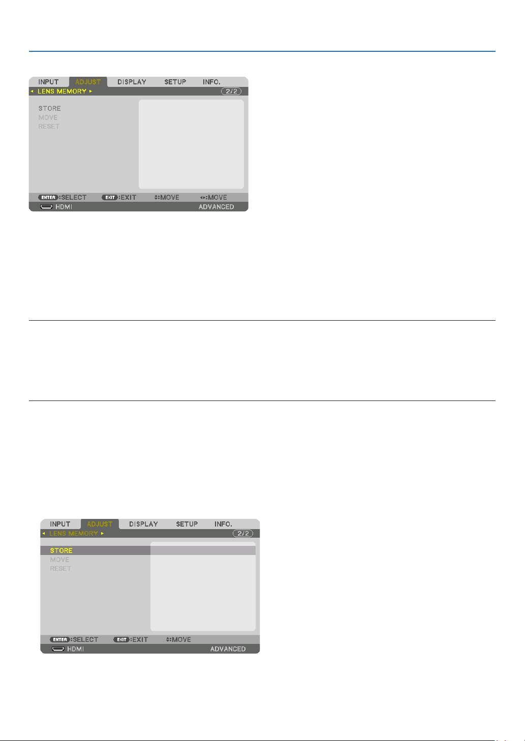
101
5. Using On-Screen Menu
Using the Lens Memory Function [LENS MEMORY]
ThisfunctionservestostoretheadjustedvaluesforeachinputsignalwhenusingtheLENSSHIFT,ZOOMandFO-
CUSbuttonsoftheprojector.Adjustedvaluescanbeappliedtothesignalyouselected.Thiswilleliminatetheneed
toadjustlensshift,focus,andzoomatthetimeofsourceselection.
STORE ������������������� Stores the current adjusted values in memory for each input signal�
MOVE �������������������� Applies the adjusted values to the current signal�
RESET �������������������� Returns the adjusted values to the last condition�
NOTE:
• LensmemoryadjustmentswillbeautomaticallyregisteredtheENTRYLIST.Theselensmemoryadjustmentscanbeloadedfrom
theENTRYLIST.(→ page 87)
Notethatperforming[CUT]or[ALLDELETE]intheENTRYLISTwilldeletelensmemoryadjustmentsaswellassourceadjust-
ments.Thisdeletionwillnottakeeffectuntilotheradjustmentsisloaded.
• Forstoringeachadjustmentoflensshift,zoomandfocusascommonvalueforallinputsignal,storethemasreferencelens
memory.
Tostoreyouradjustedvaluesin[LENSMEMORY]:
1. Project the connected device signal you want to adjust.
2. Adjusttheprojectingimageofposition,sizeandfocusbytheLENSSHIFT/HOMEPOSITION,ZOOM+/−,
andFOCUS+/−buttons.
• Adjustmentcanbeperformedbytheremotecontrol.Pleasereferto“AdjustingthePictureSizeandPosition”on
page22.
• Slightadjustmentbymovingtheprojectorpositionandbythetiltfootisnotsubjectof[LENSMEMORY].
3.Movethecursoron[STORE]andpressENTER.
4.Movethecursoron[YES]andpressENTER.
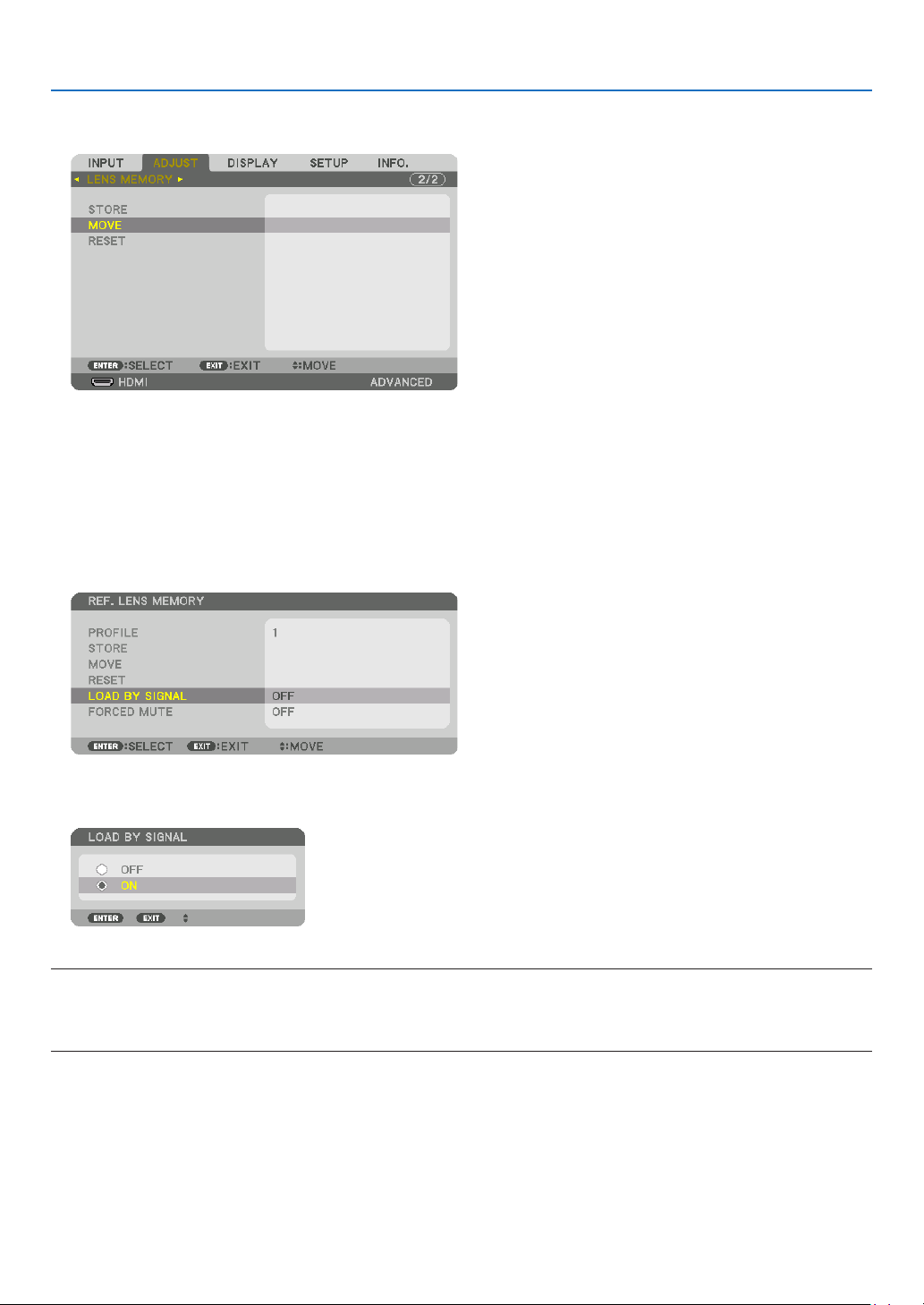
102
5. Using On-Screen Menu
Tocalluptheadjustedvaluesfrom[LENSMEMORY]:
1. Fromthemenu,select[ADJUST]→[LENSMEMORY]→[MOVE]andpresstheENTERbutton.
Theconrmationscreenwillbedisplayed.
2. Press the ◀buttontoselectand[YES]andpresstheENTERbutton.
Duringprojection,iftheadjustedvaluesforaninputsignalhavebeensaved,thelenswillshift.Ifnot,thelenswill
shiftaccordingtotheadjustedvaluesstoredintheselected[REF.LENSMEMORY][PROFILE]number.
Toautomaticallyapplytheadjustedvaluesatthetimeofsourceselection:
1. Fromthemenu,select[SETUP]→[INSTALLATION(2)]→[REF.LENSMEMORY]→[LOADBYSIGNAL]and
press the ENTER button.
2. Press the ▼buttontoselectand[ON]andpresstheENTERbutton.
Thiswillmovethelensautomaticallytothepositionatthetimeofsourceselectionaccordingtotheadjustedvalues.
NOTE:
• TheLensMemoryfunctionmaynotproduceacompletelyalignedimage(duetotolerancesinthelenses)usingtheadjusted
valuesstoredintheprojector.AftercallingupandapplyingtheadjustedvaluesfromtheLensMemoryfunction,nelyadjustthe
lensshift,zoomandfocustoproducethebestpossibleimage.

103
5. Using On-Screen Menu
❻ Menu Descriptions & Functions [DISPLAY]
[PIP/PICTURE BY PICTURE]
SUBINPUT
Selecttheinputsignaltobedisplayedinthesub-display.
Pleasereferto“4-2DisplayingTwoPicturesattheSameTime”(→page68)fordetailsontheoperation.
MODE
SelecteitherPIPorPICTUREBYPICTUREwhenswitchingto2-screendisplay.
PICTURE SWAP
Thevideosinthemaindisplayandsub-displaywillbeswitched.
Pleasereferto“4-2DisplayingTwoPicturesattheSameTime”(→page70)fordetails.
PIP SETTING
Selectthedisplayposition,positionadjustmentandsizeofthesub-displayinthePIPscreen.
START POSITION ��� Selection of the display position of the sub-display when switching to the PIP screen�
HORIZONTAL POSITION
������������������������������ Adjust the display position of the sub-display in the horizontal direction� The respective corners will serve
as reference points�
VERTICAL POSITION
������������������������������ Adjust the display position of the sub-display in the vertical direction� The respective corners will serve as
reference points�
SIZE ����������������������� Select the display size of the sub-display�
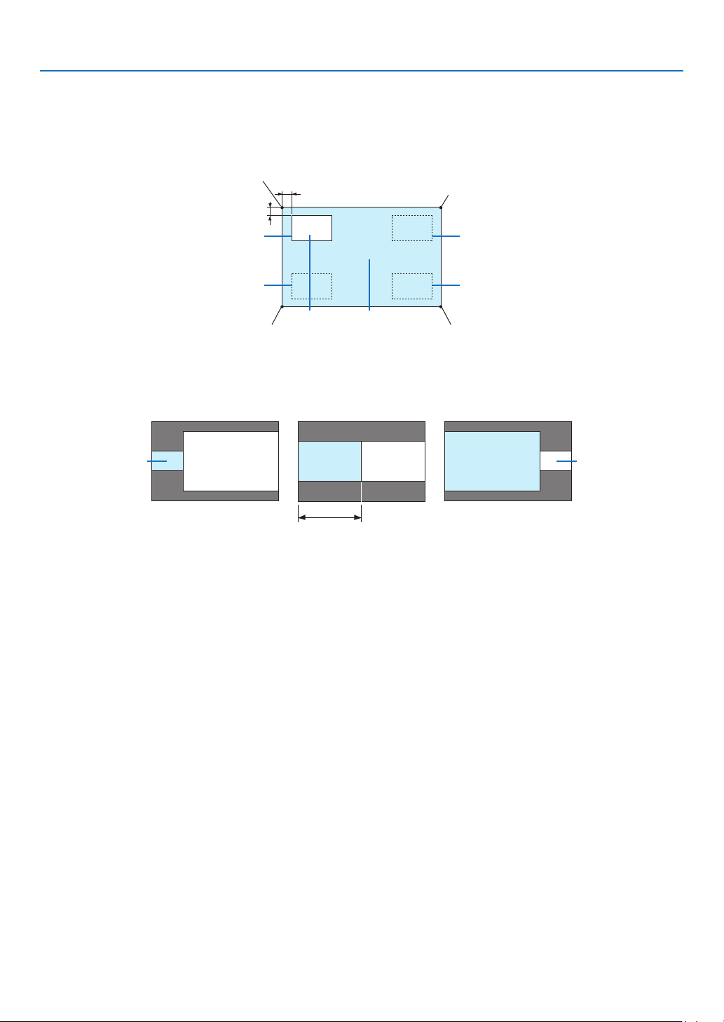
104
5. Using On-Screen Menu
TIP:
Thehorizontalpositionandverticalpositionaretheamountofmovementfromthereferencepoints.Forexample,whenTOP-LEFT
isadjusted,thepositionisdisplayedwiththesameamountofmovementevenifdisplayedwithotherstartingpositions.
Themaximumamountofmovementishalftheresolutionoftheprojector.
Referencepoint
Adjustusingthehorizon-
talposition
Sub-display Maindisplay
Referencepoint
Adjustusingtheverticalposition
TOP-LEFT TOP-RIGHT
BOTTOM-LEFT BOTTOM-RIGHT
ReferencepointReferencepoint
BORDER
Selectthedisplayboundaryofthemaindisplayandsub-displayofthe[PICTUREBYPICTURE]screen.
Displayboundary
Maindisplay
Sub-displayMaindisplay
Sub-display
MaindisplaySub-display
TIP:
• 6stepscanbeselectedonthisprojector.
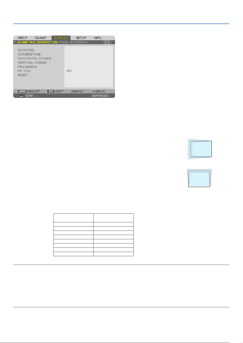
105
5. Using On-Screen Menu
[GEOMETRIC CORRECTION]
KEYSTONE
Displaythetrapezoidcorrectionscreenandadjustthetrapezoidaldistortionoftheprojectionscreen.
Todisplaythe[KEYSTONE]screen,select→[DISPLAY]→[GEOMETRICCORRECTION]→[KEYSTONE]inthe
on-screenmenu.The[GEOMETRICCORRECTION]screen canalsobe displayedbypressingthe 3DREFORM
buttonontheremotecontrol.
HORIZONTAL ��������� Adjustments when projecting from a diagonal direction to the
screen�
VERTICAL �������������� Adjustments when projecting from the top or bottom direction to
the screen�
TILT ����������������������� Adjusts the distortion when performing trapezoidal correction with the screen moved in the vertical direction
using the lens shift�
THROW RATIO ������� Adjusts according to the projection ratio of the optional lens used�
Modelnameoflens
unit
Adjustmentrange
NP16FL 7–8
NP17ZL 12–18
NP18ZL 17–23
NP19ZL 21–37
NP20ZL 34–55
NP21ZL 50–85
NP31ZL 7–10
NP39ML 4
NOTE:
• Whenpowerissuppliedtothedevice,theadjustmentvalueofthe[KEYSTONE]usedpreviouslyisretainedevenifthegradient
ofthedeviceischanged.
• Whenclearingtheadjustmentvalueof[KEYSTONE],pressthe3DREFORMbuttonfor2ormoreseconds.
• Whensettingother[GEOMETRICCORRECTION]functions,the[KEYSTONE]menucannotbeselected.Whenperformingtrapezoidal
correction,pressthe3DREFORMbuttonfor2ormoresecondstocleartheadjustmentvalueof[GEOMETRICCORRECTION].
• Aselectricalcorrectionis carriedoutby[KEYSTONE], thebrightnessmaybe reducedorthescreen qualitymaydeteriorate
sometimes.
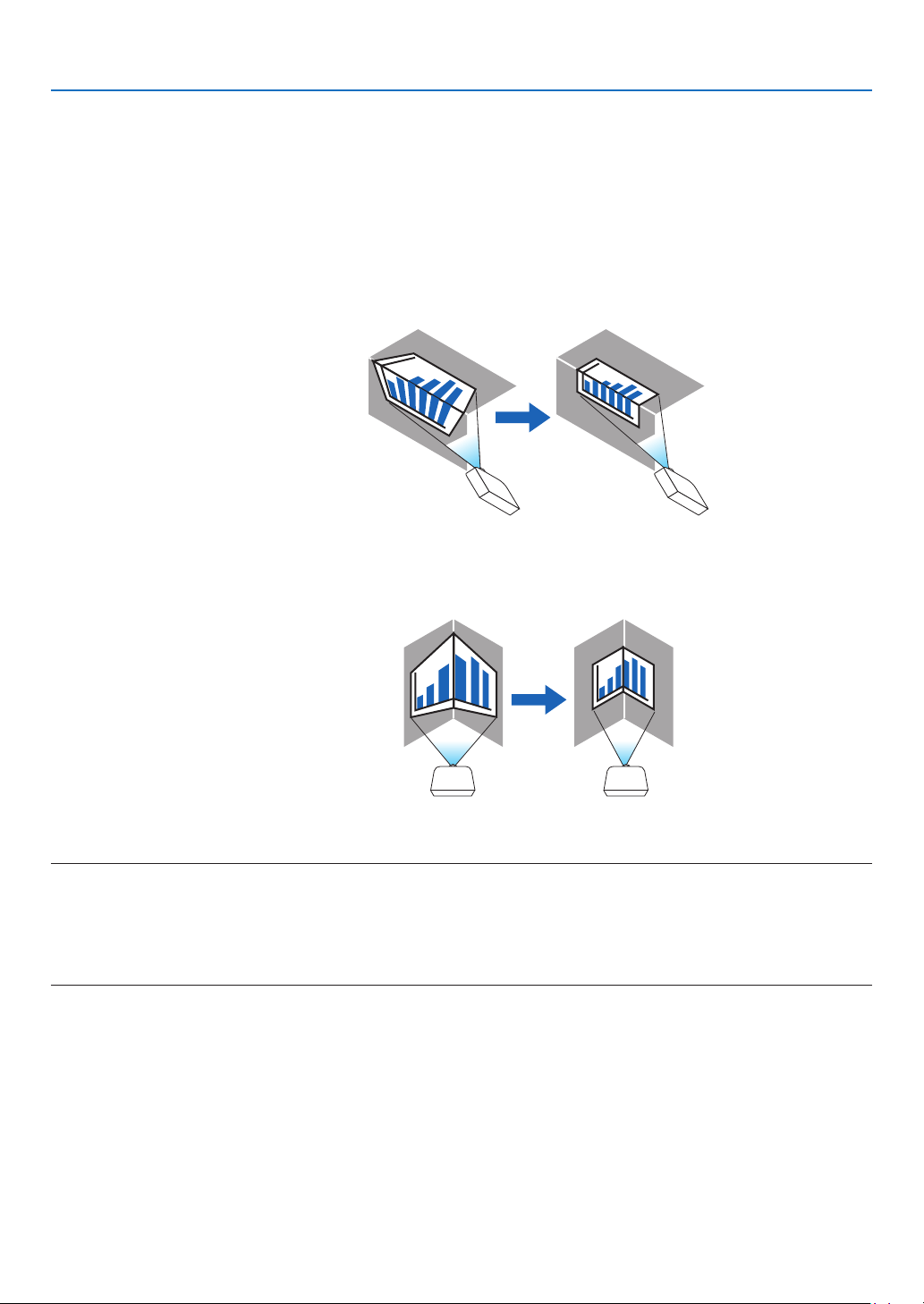
106
5. Using On-Screen Menu
CORNERSTONE
Displaythe4-pointcorrectionscreenandadjustthetrapezoidaldistortionoftheprojectionscreen.
Pleasereferto“CorrectingHorizontalandVerticalKeystoneDistortion[CORNERSTONE]”(→page42)fordetails
ontheoperation.
HORIZONTALCORNER/VERTICALCORNER
Distortioncorrectionforcornerprojectionsuchaswallsurfaces.
HORIZONTAL CORNER
������������������������������ Performs correction for projection onto a wall lying at an angle to the horizontal direction�
* Reverse angle correction is also possible�
VERTICAL CORNER
������������������������������ Performs correction for projection onto a wall lying at an angle to the vertical direction�
* Reverse angle correction is also possible�
NOTE:
• Whenthemaximumadjustmentrangeisexceeded,distortionadjustmentisdisabled.Setuptheprojectoratanoptimalangleas
thedeteriorationintheimagequalityincreasesasthedistortionadjustmentvolumegetslarger.
• Pleasenotethattheimagewillgooutoffocusduetothedifferenceinthedistancebetweentheupperandlowerorleftandright
sidesandthecenterofthescreenforprojectionscuttingacrosscorners.Lenseswithshortfocalpointsarealsonotrecommended
forprojectionscuttingacrosscornersastheimagewillgooutoffocus.
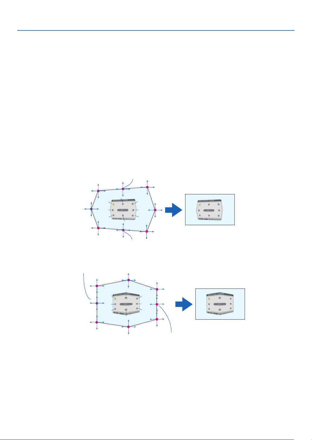
107
5. Using On-Screen Menu
Adjustment method
1. Alignthecursorwiththe[HORIZONTALCORNER]or[VERTICALCORNER]ofthe[GEOMETRICCORREC-
TION]menuandthenpresstheENTERbutton.
• Theadjustmentscreenwillbedisplayed.
2. Press the ▼▲◀▶ buttons to align the cursor (yellow box) with the target adjustment point and then press
the ENTER button.
• Thecursorwillchangeintoanadjustmentpoint(yellowincolor).
3. Press the ▼▲◀▶buttonstoadjustthecornersorsidesofthescreenandthenpresstheENTERbutton.
• Theadjustmentpointwillgobacktobeingacursor(yellowbox).
Explanationofscreentransition
• Theadjustmentpointsofthefourcorners(a,c,fandhinthedrawing)willmoveindependently.
• Thefollowingadjustmentpointsdifferatthe[HORIZONTALCORNER]and[VERTICALCORNER].
HORIZONTALCORNER:WhenPointbinthedrawingismoved,andtheuppersideandPointgaremoved,the
lowersidewillmoveinaparallelmanner.
VERTICALCORNER:WhenPointdinthedrawingismoved,andtheleftsideandPointearemoved,theright
sidewillmoveinaparallelmanner.
[Adjustmentpointsofthe[HORIZONTALCORNER]screenandmovementpointsoftheprojectionscreen]
a
b
b
c
d
e
f
g
h
a
c
d
e
f
g
h
PointbwillbedisplacedinaparallelmanneratthesametimeasPointsa,b,c
PointgwillbedisplacedinaparallelmanneratthesametimeasPointsf,g,h
[Adjustmentpointsofthe[VERTICALCORNER]screenandmovementpointsoftheprojectionscreen]
a
a
b
b
c
c
d
d
e
e
f
f
g
g
h
h
PointdwillbedisplacedinaparallelmanneratthesametimeasPointsa,d,f
PointewillbedisplacedinaparallelmanneratthesametimeasPointsf,g,h
4. StartfromStep2onwardstoadjusttheotherpoints.
5. When the adjustment is completed, press the ▼▲◀▶ buttonstoalignthe cursorwiththe[EXIT]inthe
adjustment screen and then press theENTER button.
• Switchtothe[GEOMETRICCORRECTION]menuscreen.

108
5. Using On-Screen Menu
PINCUSHION
Adjustthecurvedistortionoftheprojectionscreen.
TOP ������������������������ Adjust the curve distortion of the upper edge of the projection
screen�
BOTTOM ���������������� Adjust the curve distortion of the lower edge of the projection
screen�
LEFT ���������������������� Adjust the curve distortion of the left edge of the projection screen�
RIGHT �������������������� Adjust the curve distortion of the right edge of the projection
screen�
TOP
LEFT RIGHT
BOTTOM
PCTOOL(Forfuturesupport)
Recallthegeometriccorrectiondatathatisregisteredintheprojectorbeforehand.
Therearethreetypesofregistereddata.
NOTE:
• KEYSTONE,CORNERSTONE,andPINCUSHIONcannotbeselectedwhensettingthegeometriccorrectionusingaPCtool.
• Toclearthe[GEOMETRICCORRECTION]datathathasbeensetup,pressthe3DREFORMbuttonfor2ormoreseconds.
• Aselectricalcorrectioniscarriedoutingeometriccorrection,thebrightnessmaybeaffectedandthepicturequalitymaybe
degraded.
RESET
ResettheadjustmentvaluethathasbeensetupinGEOMETRICCORRECTION(returntotheinitialvalue).

109
5. Using On-Screen Menu
[EDGE BLENDING]
Thisadjuststheedges(boundaries)oftheprojectionscreenwhenprojectinghighresolutionvideosusingacombina-
tionofseveralprojectorsintheup,down,leftandrightpositions.
MODE
ThisenablesordisablestheEDGEBLENDINGfunction.
WhenMODEissettoON,theTOP,BOTTOM,LEFT,RIGHTandBLACKLEVELsettingscanbeadjusted.
TOP/BOTTOM/LEFT/RIGHT
ThisselectstheEDGEBLENDINGlocationsontheleft,right,topandbottomonthescreen.
Thefollowingsettingscanbeadjustedwhenanitemisselected.(→page73)
CONTROL �������������� Enable TOP, BOTTOM, LEFT and RIGHT functions�
MARKER ���������������� Set whether to display marker or not when adjusting the range and display position� When turned on, a
magenta marker for adjusting the range adjustment and a green marker for adjusting the display position
will be displayed�
RANGE ������������������� Adjust the range (width) of the edge blending�
POSITION �������������� Adjust the display position of the edge blending�
BLACKLEVEL
Dividethescreenintoninepartsandkeeptheblackleveluniformforeachprojector.
TheninedivisionsscreensareTOP-LEFT,TOP-CENTER,TOP-RIGHT,CENTER-LEFT,CENTER,CENTER-RIGHT,
BOTTOM-LEFT,BOTTOM-CENTERandBOTTOM-RIGHT.(→page76)

110
5. Using On-Screen Menu
[MULTI SCREEN]
WHITEBALANCE
Thisadjuststhewhitebalanceforeachprojectorwhenprojectingusingacombinationofseveralprojectors.
Thiscanbeadjustedwhen[MODE]issetto[ON].
BRIGHTNESS W, BRIGHTNESS R, BRIGHTNESS G, BRIGHTNESS B
������������������������������ Adjusting the black color of the video�
CONTRAST W, CONTRAST R, CONTRAST G, CONTRAST B
������������������������������ Adjusting the white color of the video�
PICTURE SETTING
Thissetsthedivisionconditionwhenprojectingusingacombinationofseveralprojectors.
Pleasereferto“4.Multi-ScreenProjection”(→page64)fordetails.
MODE OFF Usetheprojectorinastandalonestate.
ZOOM Thisadjuststhepositionandwidthofthevideoareathatyouwishtodivide.Theedge
blendingwidthwillalsobeautomaticallysettothatwidth.
TILING Thisassignsthedividedscreenstotheprojectors.Theedgeblendingfunctionwillalso
besetautomatically.
ZOOM HORIZONTAL
ZOOM
Thismaginiesthevideoareainthehorizontaldirection.
VERTICAL
ZOOM
Thismaginiesthevideoareaintheverticaldirection.
HORIZONTAL
POSITION
Thisshiftsthevideoareainthehorizontaldirection.
VERTICALPO-
SITION
Thisshiftsthevideoareaintheverticaldirection.
TILING WIDTH Thisselectsthenumberofprojectorstobearrangedhorizontally.
HEIGHT Thisselectsthenumberofprojectorstobearrangedvertically.
HORIZONTAL
POSITION
Thisselectsthepositionoftheprojectorstartingfromtheleftamongthosearranged
horizontally.
VERTICALPO-
SITION
Thisselectsthepositionoftheprojectorstartingfromthetopamongthosearranged
vertically.
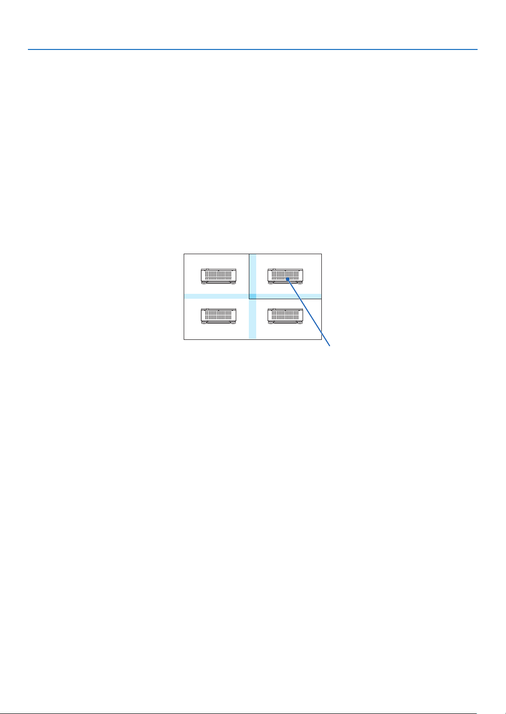
111
5. Using On-Screen Menu
Conditions for using tiling
• Alltheprojectorsneedtofullthefollowingconditions.
• Thepanelsizemustbethesame
• Theprojectionscreensizemustbethesame
• Theleftandrightendsortopandbottomendsoftheprojectionscreenmustbeconsistent.
• Thesettingsfortheleftandrightedgesoftheedgeblendingarethesame
• Thesettingsforthetopandbottomedgesoftheedgeblendingarethesame
Ifthetilingconditionsaresatised,thevideoscreenoftheprojectorateachinstallationpositionwillbeautomatically
extractedandprojected.
Ifthetilingconditionsarenotsatised,adjustthevideoscreenoftheprojectorateachinstallationpositionusing
thezoomfunction.
• AssignauniquecontrolIDtoeachprojector.
• Setthe“ColorSetting”and“DeepColorSetting”onyourBlu-rayplayerorcomputerto“Auto”.Refertotheowner’s
manualaccompanyingyourBlu-rayplayerorcomputerformoreinformation.
ConnecttheHDMIoutputofyourBlu-rayplayerorcomputertotherstprojector.ThenconnecttotheHDMIINinput
terminalofthesecondandsubsequenttiledprojectors.
Tilingsettingexample)Numberofhorizontalunits=2,Numberofverticalunits=2
Horizontalorder=Secondunit
Verticalorder=Firstunit
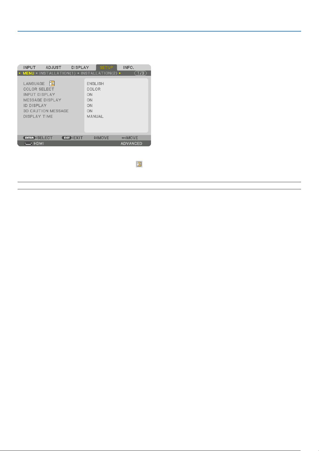
112
5. Using On-Screen Menu
❼ Menu Descriptions & Functions [SETUP]
[MENU]
SelectingMenuLanguage[LANGUAGE]
Youcanchooseoneof29languagesforon-screeninstructions.
NOTE:Yoursettingwillnotbeaffectedevenwhen[RESET]isdonefromthemenu.
SelectingMenuColor[COLORSELECT]
Youcanchoosebetweentwooptionsformenucolor:COLORandMONOCHROME.
TurningOn/OffSourceDisplay[INPUTDISPLAY]
ThisoptionturnsonoroffinputnamedisplaysuchasHDMI,DisplayPort,BNC,BNC(CV),BNC(Y/C),COMPUTER,
HDBaseTtobedisplayedonthetoprightofthescreen.
Turningmessagesonandoff[MESSAGEDISPLAY]
Thisoptionselectswhetherornottodisplayprojectormessagesatthebottomoftheprojectedimage.
Evenwhen“OFF”isselected,thesecuritylockwarningisdisplayed.Thesecuritylockwarningturnsoffwhenthe
securitylockiscanceled.
TurningON/OFFControlID[IDDISPLAY]
ID DISPLAY ����������� This option turns on or off the ID number which is displayed when the ID SET button on the remote control
is pressed� (→ page 125)

113
5. Using On-Screen Menu
[3DCAUTIONMESSAGE]
Thisselectswhethertodisplayacautionmessageornotwhenswitchingtoa3Dvideo.
ThedefaultconditionwhenshippedfromthefactoryisON.
OFF ������������������������ The 3D caution message screen will not be displayed�
ON ������������������������� The 3D caution message screen will be displayed when switching to a 3D video� Press the ENTER button
to cancel the message�
• Themessagewilldisappearautomaticallyafter60secondsorwhenotherbuttonsarepressed.Ifitdisap-
pears automatically, the 3D caution message will be displayed again when switching to a 3D video�
SelectingMenuDisplayTime[DISPLAYTIME]
Thisoptionallowsyoutoselecthowlongtheprojectorwaitsafterthelasttouchofabuttontoturnoffthemenu.The
presetchoicesare[MANUAL],[AUTO5SEC],[AUTO15SEC],and[AUTO45SEC].The[AUTO45SEC]isthefac-
torypreset.
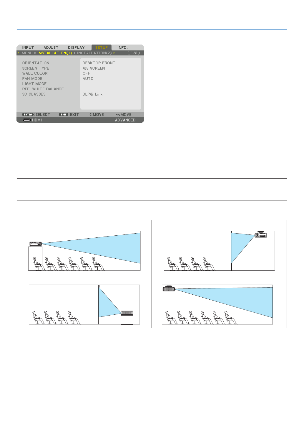
114
5. Using On-Screen Menu
[INSTALLATION(1)]
SelectingProjectorOrientation[ORIENTATION]
Thisreorientsyourimageforyourtypeofprojection.Theoptionsare:desktopfrontprojection,ceilingrearprojection,
desktoprearprojection,andceilingfrontprojection.
NOTE:
• Pleaseconsultthedealerifyourequirespecialinstallationservicese.g.whenmountingtheprojectortoaceiling.Neverinstall
theprojectoronyourown.Thismayresultintheprojectorfallingdownandcausinginjurytopeople.
AUTO ��������������������� This automatically detects and projects the DESKTOP FRONT and CEILING FRONT�
NOTE:
• TheDESKTOPREARandCEILINGREARwillnotbedetected.Pleaseselectmanually.
DESKTOPFRONT CEILINGREAR
DESKTOPREAR CEILINGFRONT
TIP:
• CheckwhethertheautomaticDESKTOPFRONTisinstalledwithin±10degreesforoorinstallationandwhethertheCEILING
FRONTiswithin±10degreesforceilinginstallation.Selectmanuallywhentheprojectionscreenisinverted.
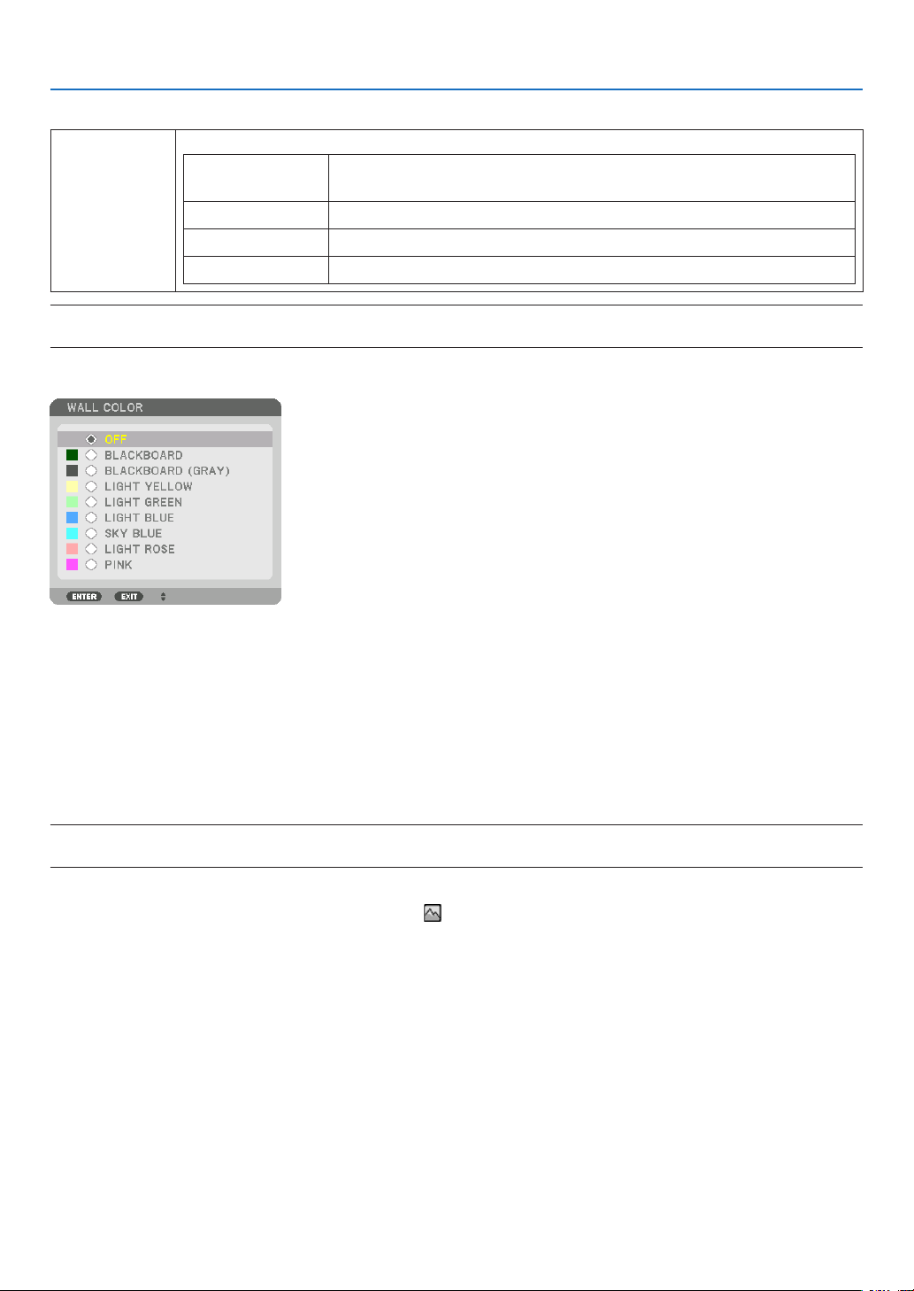
115
5. Using On-Screen Menu
SelectingAspectRatioandPositionforScreen[SCREENTYPE]
Screentype Setstheaspectratiooftheprojectionscreen.
FREE Theratiooftheliquidcrystalpanelisselected.Selectthiswhenprojecting
multi-screenand17:9screen(2K).
4:3screen Forascreenwitha4:3aspectratio
16:9screen Forascreenwitha16:9aspectratio
16:10screen Forascreenwitha16:10aspectratio
NOTE:
•
Afterchangingthescreentype,checkthesettingof[ASPECTRATIO]inthemenu.(→ page 96)
UsingtheWallColorCorrection[WALLCOLOR]
Thisfunctionallowsforquickadaptivecolorcorrectioninapplicationswherethescreenmaterialisnotwhite.
SelectingFanMode[FANMODE]
FanModeisusedtosetthespeedoftheinternalcoolingfan.
MODE �������������������� Select mode for fan speed: AUTO and HIGH�
AUTO: The built-in fans automatically run at a variable speed depending on the temperature and atmospheric
pressure sensor�
HIGH: The built-in fans run at a high speed� Select this option for continuously using the projector for
several days�
NOTE:
• Yoursettingwillnotbeaffectedevenwhen[RESET]isdonefromthemenu.
TIP:
• When[HIGH]isselectedfor[FANMODE],asymbolicon willbedisplayedatthebottomofthemenu.

116
5. Using On-Screen Menu
[LIGHTMODE]
Adjustingtheenergysavingssettingsandthebrightnessofeachprojectorin multi-screenprojection.Forenergy
savingssettings,seepage39“3-6.ChangingLIGHTMODE/CheckingEnergy-SavingEffectUsingLIGHTMODE
[LIGHTMODE]”.
LIGHTMODE NORMAL Thelightmoduleluminance(brightness)willbecome100%andthescreenwillturnbright.
ECO1 Bycontrollingthebrightnessandfanspeedaccordingtotheselectedsetting,energycan
besavedandmotionnoiseandthepowerconsumptioncanbelowered.
Canbeselectedwhen[CONSTANTBRIGHTNESS]modeissetto[OFF].
ECO2
CONSTANT
BRIGHTNESS
OFF [CONSTANTBRIGHTNESS]modewillbecanceled.
ON Maintainsthebrightnessthatisineffectatthetime[ON]isselected.Unless[OFF]isse-
lected,thesamesettingswillremainineffectevenwhentheprojectoristurnedoff.
• Tore-adjustthebrightness,rstturnthissettingOFFbeforemakingfurtheradjustments.
NOTE:
• [CONSTANTBRIGHTNESS]modeisafunctionusedtomaintainthebrightnessataconstant
level.Colorwillnotbexed.
ADJUST Brightnesscanbeadjustedin1%incrementsfrom20to100%.
Whenseveralprojectorsareusedformulti-screenprojection,thebrightnesscanbead-
justedindividuallyoneachprojector.
Theadjustmentiseffectivewhen[NORMAL][LIGHTMODE]isselectedand[CONSTANT
BRIGHTNESS]modeisturned[OFF].
TIP:
• Brightnessnormallydecreaseswithuse,butbyselecting[CONSTANTBRIGHTNESS]mode,sensorsinsidetheprojectordetect
brightnessandautomaticallyadjusttheoutput,therebymaintainingaconstantbrightnessthroughoutthelifeofthelightmodule.
However,ifoutputisalreadyatitsmaximum,brightnesswilldecreasewithuse.
Forthisreason,whenusingmulti-screenprojection,itisrecommendedtoadjustthebrightnesstoaslightlylowerlevel,then
settingthe[CONSTANTBRIGHTNESS]modeto[ON].
[REF.WHITEBALANCE]
Thisfeatureallowsyoutoadjustthewhitebalanceforallsignals.
Thewhiteandblacklevelsofthesignalareadjustedforoptimumcolorreproduction.
CONTRAST R/CONTRAST G/CONTRAST B
������������������������������ These adjust the picture’s white color�
BRIGHTNESS R/BRIGHTNESS G/BRIGHTNESS B
������������������������������ These adjust the picture’s black color�
3D GLASSES
Select3Dglassesmethod.
DLP® Link ������������� Select when using DLP
®
Link type 3D glasses�
OTHERS ����������������� Select when using a non 3D emitter type glasses� It is required to connect the 3D emitter to the 3D SYNC
terminal of this projector� Please refer to page 50 about recommended items of 3D glasses and 3D emitter
for this projector�

117
5. Using On-Screen Menu
[INSTALLATION(2)]
[SHUTTERSETTINGS]
Enablinganddisablingthelensshutterfunction.Youcanalsosethowlongthelightwilltaketofadeinandfadeoutwhen
eithertheSHUTTERbuttonontheremotecontrolortheSHUTTER/CALIBRATIONbuttononthecabinetispressed.
POWERON
SHUTTER
OPEN
When the poweristurned on,thelightsourcecomeson and the picture is
projected.
CLOSE
Thelightsourcedoesnotcomeonwhenthepoweristurnedon.
WhentheSHUTTERbuttonispressed,theshutterisreleasedandthelight
sourceisturnedon.
PICTUREMUTE
SHUTTER
OPEN Thelightsourceisstillonwhenthepictureisturnedoffforswitchingtheinput
terminals.
CLOSE
Thelightsourceturnsoffwhenthepictureisturnedoffforswitchingtheinput
terminals.
FADEINTIME SethowlongthelightwilltaketofadeinaftertheSHUTTERbuttonispressed.
Thetimecanbesetfrom0to10secondsinincrementsof1second.
FADEOUTTIME SethowlongthelightwilltaketofadeoutaftertheSHUTTERbuttonispressed.
Thetimecanbesetfrom0to10secondsinincrementsof1second.

118
5. Using On-Screen Menu
UsingtheReferenceLensMemoryFunction[REF.LENSMEMORY]
ThisfunctionservestostoretheadjustedvaluescommontoallinputsourceswhenusingtheLENSSHIFT,ZOOM
andFOCUSbuttonsoftheprojectorortheremotecontrol.Theadjustedvaluesstoredinmemorycanbeusedasa
referencetothecurrent.
PROFILE ���������������� Select a stored [PROFILE] number�
STORE ������������������� Stores the current adjusted values in memory as a reference�
MOVE �������������������� Applies the adjusted reference values stored in [STORE] to the current signal�
RESET �������������������� Reset selected [PROFILE] number [REF� LENS MEMORY] to the factory default settings�
LOAD BY SIGNAL �� When you switch signals the lens will shift to the lens shift, zoom, and focus values for the selected [PRO-
FILE] number�
If no adjusted values have been saved to [LENS MEMORY], the lens will apply [REF� LENS MEMORY]
adjusted values� Alternatively, if no adjusted values have been saved to [REF� LENS MEMORY], the unit will
return to factory default settings�
FORCED MUTE ������ To turn off the image during lens shift, select [YES]�
NOTE:
• Adjustedvaluesin[REF.LENSMEMORY]willnotbereturnedtodefaultwhenperforming[CURRENTSIGNAL]or[ALLDATA]for
[RESET]fromthemenu.
• Tostoreadjustedvaluesforeachinputsource,usetheLensMemoryfunction.(→ page 58, 101)
• When[PICTUREMUTESHUTTER]under[SHUTTERSETTINGS]is[ON],[FORCEDMUTE]willturnoffthelightsourceandstop
projection.(→ previouspage)
[LENSCALIBRATION]
Theadjustmentrangeofthezoom,focus,andshiftofthe[LENSMEMORY]iscalibrated.
Besuretocarryout[LENSCALIBRATION]afterreplacingthelens.
[LENSPOSITION]
Movethelensposition.
HOME �������������������� Set back the lens to the home position�
TYPE ���������������������� Select this for using the lens unit NP39ML� The lens position will be adjusted to the appropriate position�
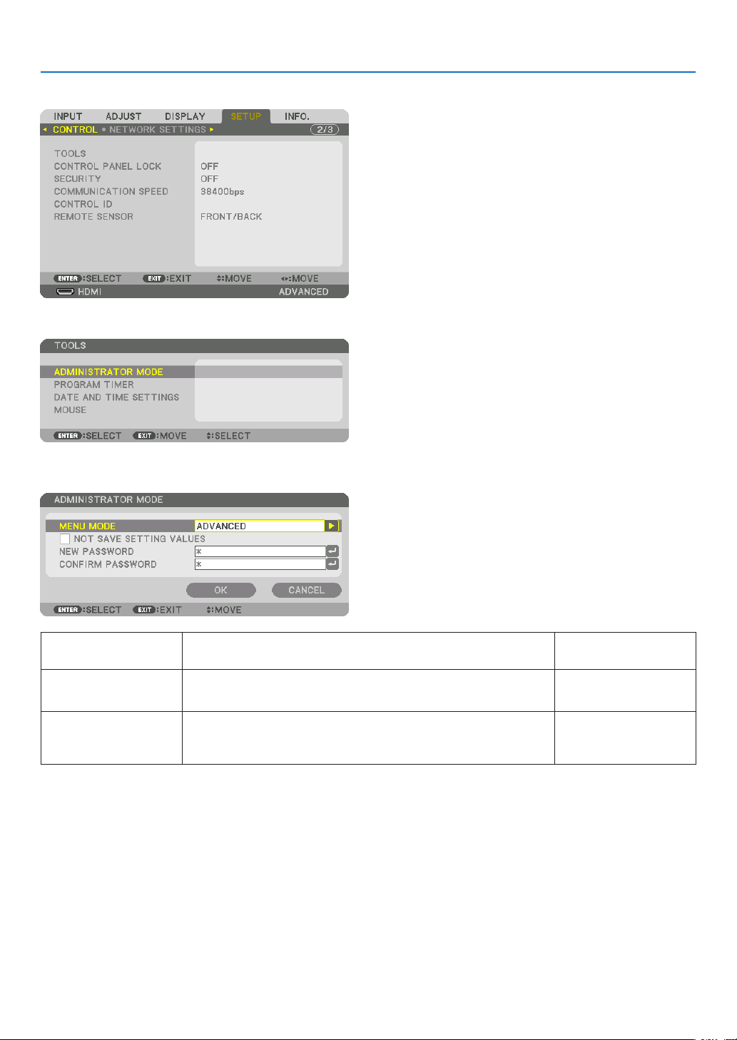
119
5. Using On-Screen Menu
[CONTROL]
TOOLS
ADMINISTRATORMODE
ThisallowsyoutoselectMENUMODE,savesettings,andsetapasswordfortheadministratormode.
MENUMODE Selecteither[BASIC]or[ADVANCED]menu.
(→page80)
—
NOTSAVESETTING
VALUES
Placing a check mark will not save your projector settings�
Clear this check box to save your projector settings�
—
NEWPASSWORD/
CONFIRMPASS-
WORD
Assignapasswordfortheadministratormode. Upto10alphanumeric
characters
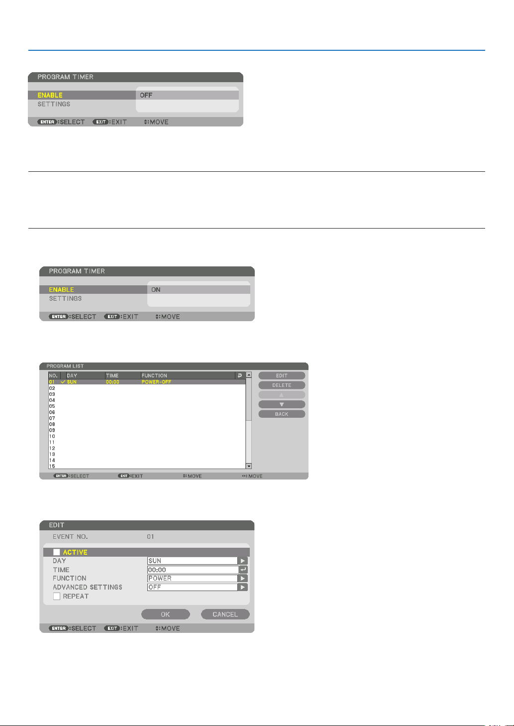
120
5. Using On-Screen Menu
PROGRAMTIMER
Thisoptionturnson/standbytheprojectorandchangesvideosignals,andselectsLIGHTmodeautomaticallyata
speciedtime.
NOTE:
• Beforeusing[PROGRAMTIMER],makesurethatthe[DATEANDTIME]featureisset.(→ page 123)
MakesurethattheprojectorisinthestandbyconditionwiththePOWERcordconnected.
Theprojectorhasabuilt-inclock.Theclockwillkeepworkingforabouttwoweeksafterthemainpoweristurnedoff.Ifthemain
powerisnotsuppliedtotheprojectorfortwoweeksormore,itrequirestoset[DATEANDTIMESETTINGS]featureagain.
Setting a new program timer
1. On the PROGRAM TIMER screen, use the ▲ or ▼buttontoselect[SETTINGS]andpresstheENTERbutton.
The[PROGRAMLIST]screenwillbedisplayed.
2. Select a blank program number and press the ENTER button.
The[EDIT]screenwillbedisplayed.
3. Makesettingsforeachitemasrequired.
ACTIVE ������������������ Place a check mark to enable the program�
DAY ������������������������ Select days of the week for the program timer� To execute the program from Monday to Friday, select [MON-
FRI]� To execute the program in everyday basis, select [EVERYDAY]�
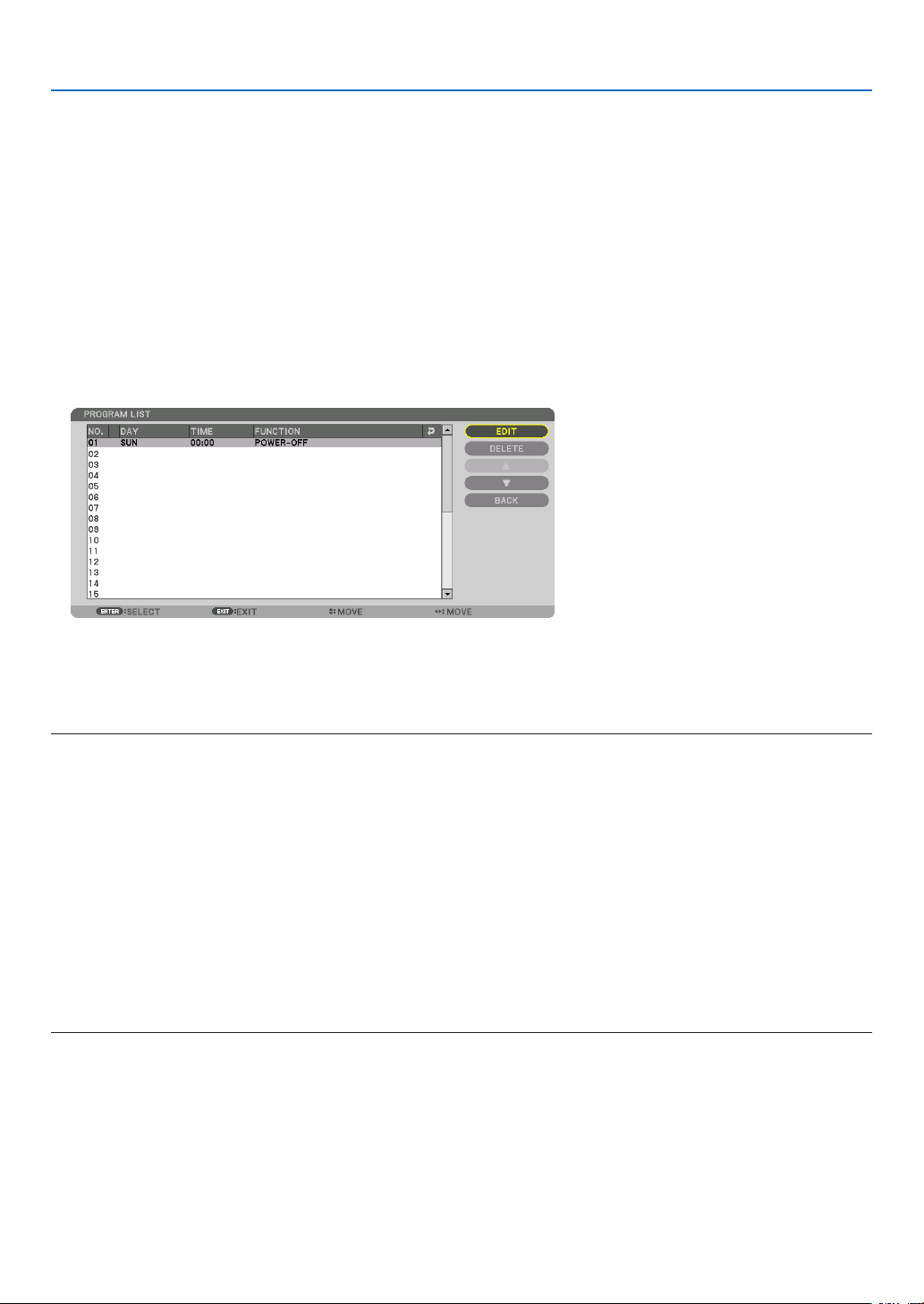
121
5. Using On-Screen Menu
TIME ���������������������� Set the time to execute the program� Enter time in 24-hour format�
FUNCTION ������������� Select a function to be executed� Selecting [POWER] will allow you to turn on or off the projector by setting
[ADVANCED SETTINGS]� Selecting [INPUT] will allow you to select a video source by setting [ADVANCED
SETTINGS]� Selecting [LIGHT MODE] will allow you to select [LIGHT MODE] by setting [ADVANCED SET-
TINGS]�
ADVANCED SETTINGS
������������������������������ Select power on/off, a type of video source, or LIGHT MODE for the selected item in [FUNCTION]�
REPEAT ������������������ Place a check mark to repeat the program continuing basis� To use the program this week only, clear the
check mark�
4. Select[OK]andpresstheENTERbutton.
Thiswillcompletethesettings.
Youwillbereturnedtothe[PROGRAMLIST]screen.
5. Select[BACK]andpresstheENTERbutton.
Youwillbereturnedtothe[PROGRAMTIMER]screen.
6. Select[EXIT]andpresstheENTERbutton.
Youwillbereturnedtothe[TOOLS]screen.
NOTE:
• Upto30differenttimersettingscanbeprogrammed.
• When[PROGRAMTIMER]isturnedon,the[STANDBYMODE]settingisignored.
• TheProgramTimerisexecutedonasettimebasis,notinaprogrambasis.
• Oncetheprogramnotmarkedwithacheckin[REPEAT]hasbeenexecuted,thecheckmarkinthe[ACTIVE]checkboxwillbe
clearedautomaticallyandtheprogramwillbedisabled.
• Whentheon-timeandtheoff-timesetforthesametime,theoff-timesettingwilltakepreference.
• Twodifferentsourcesaresetforthesametime,thelargerprogramnumberwilltakepreference.
• Theon-timesettingwillnotbeexecutedwhilethecoolingfansarerunningoranerrorisoccurring.
• Iftheoff-timesettingisexpiredundertheconditioninwhichthepoweroffisnotpossible,theoff-timersettingwillnotbeexecuted
untilthepoweroffbecomespossible.
• Programsnotmarkedwithacheckmarkin[ACTIVE]ofthe[EDIT]screenwillnotbeexecutedeveniftheProgramTimeris
enabled.
• Whentheprojectoristurnedonbyusingtheprogramtimerandifyouwanttoturnofftheprojector,settheoff-timeordoit
manuallysoasnottoleavetheprojectoronforalongperiodoftime.

122
5. Using On-Screen Menu
Activating the program timer
1. Select[ENABLE]onthe[PROGRAMTIMER]screenandpresstheENTERbutton.
Theselectionscreenwillbedisplayed.
2. Press the ▼buttontoalignthecursorwith[ON]andthenpresstheENTERbutton.
Returntothe[PROGRAMTIMER]screen.
NOTE:
• Whentheeffectivesettingsofthe[PROGRAMTIMER]havenotbeensetto[ON],theprogramwillnotbeexecutedevenifthe
[ACTIVE]itemsintheprogramlisthavebeenticked.
• Evenwhentheeffectivesettingsofthe[PROGRAMTIMER]aresetto[ON],the[PROGRAMTIMER]willnotworkuntilthe[PRO-
GRAMTIMER]screenisclosed.
Changing the programmed settings
1. Onthe[PROGRAMLIST]screen,selectaprogramyouwanttoeditandpresstheENTERbutton.
2. Changethesettingsonthe[EDIT]screen.
3. Select[OK]andpresstheENTERbutton.
Theprogrammedsettingswillbechanged.
Youwillbereturnedtothe[PROGRAMLIST]screen.
Changing the order of programs
1. Onthe[PROGRAMLIST]screen,selectaprogramwhoseorderyouwanttochangeandpressthe▶ button.
2. Press the ▼ button to select ▲ or ▼.
3. PresstheENTERbuttonafewtimestoselectarowtowhichyouwishtomovetheprogram.
Theorderoftheprogramswillbechanged.
Deleting the programs
1. Onthe[PROGRAMLIST]screen,selectaprogramnumberyouwanttodeleteandpressthe▶ button.
2. Press the ▼buttontoselect[DELETE].
3. Press the ENTER button.
Theconrmationscreenwillbedisplayed.
4. Select[YES]andpresstheENTERbutton.
Theprogramwillbedeleted.
Thiswillcompletedeletingtheprogram.

123
5. Using On-Screen Menu
DATEANDTIMESETTINGS
Youcansetthecurrenttime,month,date,andyear.
NOTE:Theprojectorhasabuilt-inclock.Theclockwillkeepworkingforabout2weeksafterthemainpoweristurnedoff.Ifthe
mainpowerisofffor2weeksormore,thebuilt-inclockwillcease.Ifthebuilt-inclockceases,setthedateandtimeagain.The
built-inclockwillnotceasewhileinthestandbymode.
TIME ZONE SETTINGS �������������� Select your time zone�
DATE AND TIME SETTINGS ������ Set your current date (MM/DD/YYYY) and time (HH:MM)�
INTERNET TIME SERVER ��������� If you place a check mark, the projector’s built-in clock will be synchronized with an Internet
time server in every 24 hours and at the time of projector’s startup�
UPDATE ������������������������������������ Synchronizes the projector’s built-in clock immediately� The UPDATE button is not available
unless the INTERNET TIME SERVER check box is turned on�
SUMMER TIME SETTINGS ������� If you place a check mark, the clock for daylight saving will be enabled�
[MOUSE]
Thisfunctioncannotbeusedinthisdevice.Itisusedforfutureexpansionpurposesonly.

124
5. Using On-Screen Menu
DisablingtheCabinetButtons[CONTROLPANELLOCK]
ThisoptionturnsonorofftheCONTROLPANELLOCKfunction.
NOTE:
• Howtocancelthe[CONTROLPANELLOCK]
Whenthe[CONTROLPANELLOCK]issetto[ON],presstheSOURCEbuttononthemainbodyforabout10secondstocancel
the[CONTROLPANELLOCK].
TIP:
• Whenthe[CONTROLPANELLOCK]isturnedon,akeylockicon[ ]willbedisplayedatthebottomrightofthemenu.
• ThisCONTROLPANELLOCKdoesnotaffecttheremotecontrolfunctions.
EnablingSecurity[SECURITY]
ThisfeatureturnsonorofftheSECURITYfunction.
Unlessthecorrectkeywordisentered,theprojectorcannotprojectanimage.(→page45)
NOTE:Yoursettingwillnotbeaffectedevenwhen[RESET]isdonefromthemenu.
SelectingCommunicationSpeed[COMMUNICATIONSPEED]
ThisfeaturesetsthebaudrateofthePCControlport(D-Sub9P).Itsupportsdataratesfrom4800to115200bps.
Thedefaultis38400bps.Selecttheappropriatebaudrateforyourequipmenttobeconnected(dependingonthe
equipment,alowerbaudratemayberecommendedforlongcableruns).
NOTE:
• Select[38400bps]orlesswhenusingthesuppliedsoftwareprograms.
• Yourselectedcommunicationspeedwillnotbeaffectedevenwhen[RESET]isdonefromthemenu.
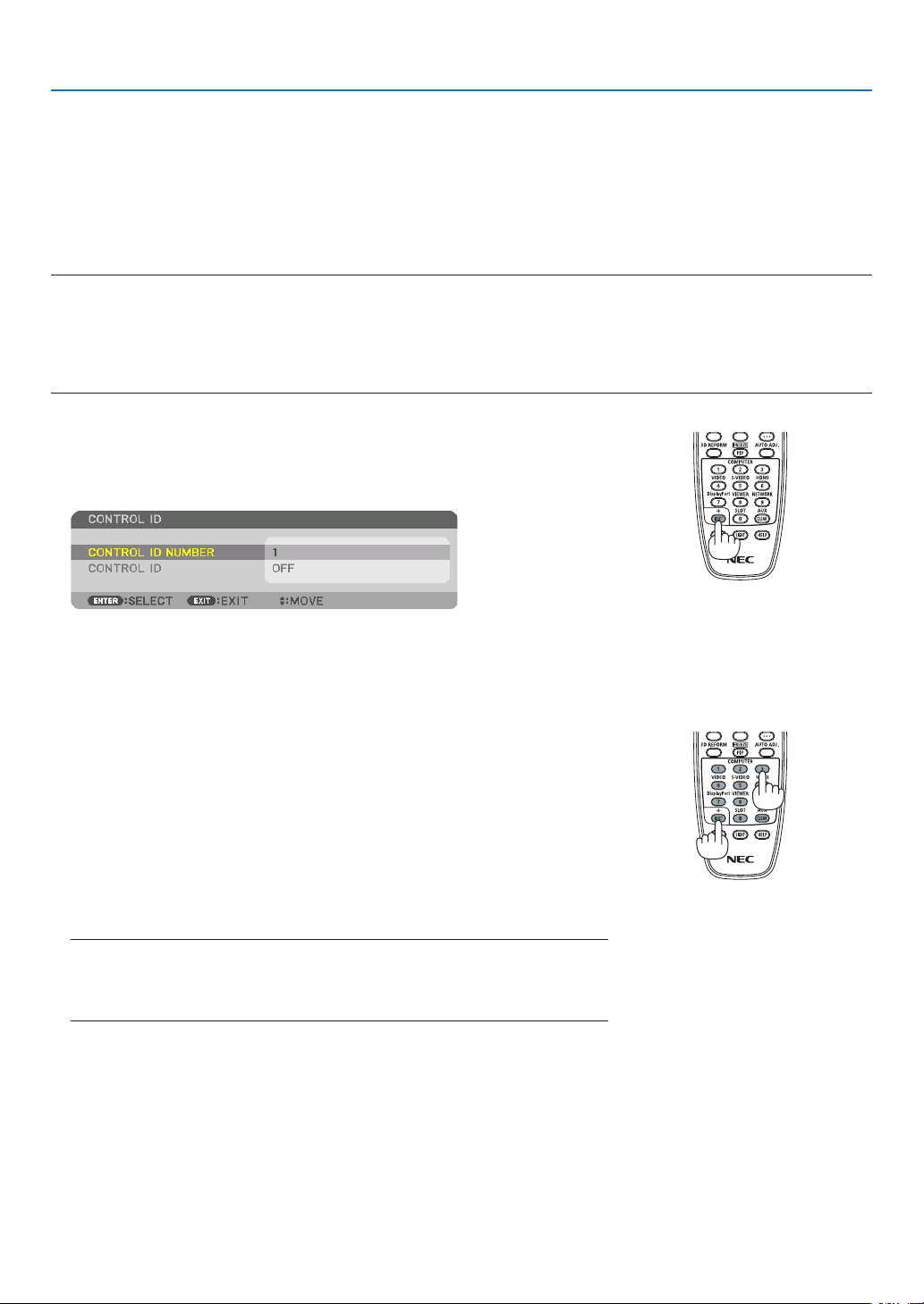
125
5. Using On-Screen Menu
SettingIDtotheProjector[CONTROLID]
YoucanoperatemultipleprojectorsseparatelyandindependentlywiththesingleremotecontrolthathastheCONTROL
IDfunction.IfyouassignthesameIDtoalltheprojectors,youcanconvenientlyoperatealltheprojectorstogether
usingthesingleremotecontrol.Todoso,youhavetoassignanIDnumbertoeachprojector.
CONTROL ID NUMBER ������� Select a number from 1 to 254 you wish to assign to your projector�
CONTROL ID �����������������������Select [OFF] to turn off the CONTROL ID setting and select [ON] to turn on the CONTROL ID setting�
NOTE:
• When[ON]isselectedfor[CONTROLID],theprojectorcannotbeoperatedbyusingtheremotecontrolthatdoesnotsupport
theCONTROLIDfunction.(Inthiscasethebuttonsontheprojectorcabinetcanbeused.)
• Yoursettingwillnotbeaffectedevenwhen[RESET]isdonefromthemenu.
• PressingandholdingtheENTERbuttonontheprojectorcabinetfor10secondswilldisplaythemenuforcancelingtheControl
ID.
Assigning or Changing the Control ID
1. Turn on the projector.
2. Press the ID SET button on the remote control.
TheCONTROLIDscreenwillbedisplayed.
IftheprojectorcanbeoperatedwiththecurrentremotecontrolID,the[AC-
TIVE]willbedisplayed.Iftheprojectorcannotbeoperatedwiththecurrent
remotecontrolID,the[INACTIVE]willbedisplayed.Tooperatetheinactive
projector,assignthecontrolIDusedfortheprojectorbyusingthefollowing
procedure(Step3).
3. PressoneofnumerickeypadbuttonswhilepressingandholdingtheID
SET button on the remote control.
Example:
Toassign“3”,pressthe“3”buttonontheremotecontrol.
NoIDmeansthatalltheprojectorscanbeoperatedtogetherwithasingle
remotecontrol.Toset“NoID”,enter“000”orpresstheCLEARbutton.
TIP:TherangeofIDsisfrom1to254.
4. Release the ID SET button.
TheupdatedCONTROLIDscreenwillbedisplayed.
NOTE:
• TheIDscanbeclearedinafewdaysafterthebatteriesarerundownorremoved.
• Ifoneofbuttonsoftheremotecontrolwithoutbatteries ispressedaccidentally,
currentspeciedIDwillbecleared.

126
5. Using On-Screen Menu
TurningOnorOffRemoteSensor[REMOTESENSOR]
Thisoptiondetermineswhichremotesensorontheprojectorisenabledinwirelessmode.
Theoptionsare:FRONT/BACK,FRONT,BACK,andHDBaseT.
NOTE:
• TheremotecontroloftheprojectorwillnotbeabletoreceivesignalsifthepowersupplyoftheHDBaseTsupportedtransmission
deviceconnectedtotheprojectoronwhich“HDBaseT”settinghasbeenON.
TIP:
• Iftheremotecontrolsystemdoesnotfunctionwhendirectsunlightorstrongilluminationstrikestheremotecontrolsensorof
the projector, change another option.

127
5. Using On-Screen Menu
[NETWORK SETTINGS]
Important:
• Consultwithyournetworkadministratoraboutthesesettings.
• WhenusingawiredLANconnection,connectaLANcable(Ethernetcable)totheLANport(RJ-45)oftheprojector.(→ page
152
)
TIP:Thenetworksettingsyoumakewillnotbeaffectedevenwhen[RESET]isdonefromthemenu.
Hints on How to Set Up LAN Connection
To set up the projector for a LAN connection:
Select[WIREDLAN]→[PROFILES]→[PROFILE1]or[PROFILE2].
TwosettingscanbesetforwiredLAN.
Nextturnonorofffor[DHCP],[IPADDRESS],[SUBNETMASK],and[GATEWAY]andselect[OK]andpressthe
ENTERbutton.(→page128)
To recall LAN settings stored in the profile number:
Select[PROFILE1]or[PROFILE2]forwiredLAN,andthenselect[OK]andpresstheENTERbutton.(→page128)
To connect a DHCP server:
Turnon[DHCP]forwiredLAN.Select[ON]andpresstheENTERbutton.TospecifyIPaddresswithoutusingthe
DHCPserver,turnoff[DHCP].(→page128)
To receive error messages via e-mail:
Select[ALERTMAIL],andset[SENDER'SADDRESS],[SMTPSERVERNAME],and[RECIPIENT'SADDRESS].
Last,select[OK]andpresstheENTERbutton.(→page130)

128
5. Using On-Screen Menu
WIRED LAN
PROFILES • Thesettingsforusingthebuilt-inEthernet/HDBaseTportinthe
projectorcanberecordedintheprojectormemoryintwoways.
• Select[PROFILE1]or[PROFILE2]andthendosettingsfor
[DHCP]andtheotheroptions.
Afterdoingthis,select[OK]andpresstheENTERbutton.This
willstoreyoursettingsinmemory.
• Torecallthesettingsfrommemory:
Afterselecting[PROFILE1]or[PROFILE2]fromthe[PRO-
FILES]list.
Select[OK]andpresstheENTERbutton.
• Select[DISABLE]whennotconnectingtoawiredLAN
—
DHCP
PlaceacheckmarktoautomaticallyassignanIPaddresstothe
projectorfromyourDHCPserver.
ClearthischeckboxtoregistertheIPaddressorsubnetmask
numberobtainedfromyournetworkadministrator.
—
IPADDRESS SetyourIPaddressofthenetworkconnectedtotheprojector
when[DHCP]isturnedoff.
Upto12numeric
characters
SUBNETMASK Setyoursubnetmasknumberofthenetworkconnectedtothe
projectorwhen[DHCP]isturnedoff.
Upto12numeric
characters
GATEWAY
Setthedefaultgatewayofthenetworkconnectedtotheprojector
when[DHCP]isturnedoff.
Upto12numeric
characters
AUTODNS PlaceacheckmarktoautomaticallyassigntheIPaddressofyour
DNSserverconnectedtotheprojectorfromyourDHCPserver.
ClearthischeckboxtosettheIPaddressofyourDNSserver
connectedtotheprojector.
Upto12numeric
characters
DNSCONFIGURA-
TION
SettheIPaddressofyourDNSserveronthenetworkconnected
totheprojectorwhen[AUTODNS]iscleared.
Upto12numeric
characters
RECONNECT
Retrytoconnecttheprojectortoanetwork.Trythisifyouhave
changed[PROFILES].
—
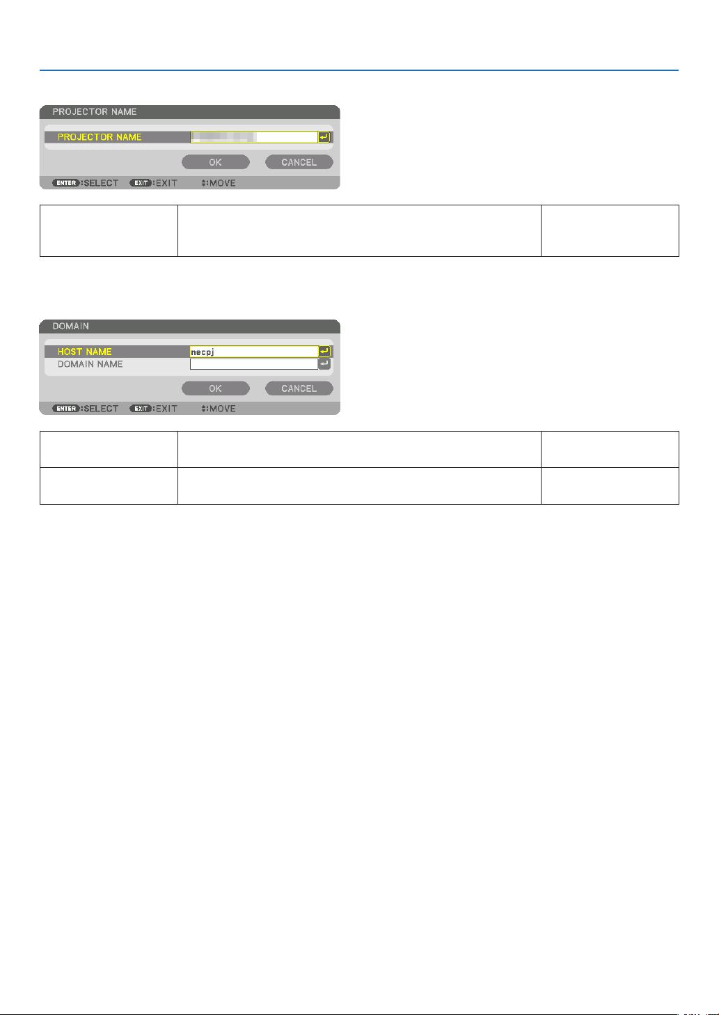
129
5. Using On-Screen Menu
PROJECTORNAME
PROJECTORNAME Setauniqueprojectorname. Upto16alphanu-
mericcharactersand
symbols
DOMAIN
Setahostnameanddomainnameoftheprojector.
HOSTNAME Setahostnameoftheprojector. Upto15alphanumeric
characters
DOMAINNAME Setadomainnameoftheprojector. Upto60alphanumeric
characters

130
5. Using On-Screen Menu
ALERTMAIL
ALERTMAIL Thisoptionwillnotifyyourcomputeroferrormessagesviae-mail
whenusingwirelessorwiredLAN.
Placing a checkmark will turn on the Alert Mail feature�
Clearing a checkmark will turn off the Alert Mail feature�
Sample of a message to be sent from the projector:
Subject:[Projector]ProjectorInformation
THECOOLINGFANHASSTOPPED.
[INFORMATION]
PROJECTORNAME:PX803ULSeries
LIGHTHOURSUSED:0000[H]
—
HOSTNAME Typeinahostname. Upto15alphanumeric
characters
DOMAINNAME Typeinadomainnameofthenetworkconnectedtotheprojector. Upto60alphanumeric
characters
SENDER'SAD-
DRESS
Specifythesender’saddress. Upto60alphanu-
mericcharactersand
symbols
SMTPSERVER
NAME
TypeintheSMTPservernametobeconnectedtotheprojector. Upto60alphanumeric
characters
RECIPIENT'SAD-
DRESS1,2,3
Typeinyourrecipient’saddress. Upto60alphanu-
mericcharactersand
symbols
TESTMAIL Sendatestmailtocheckifyoursettingsarecorrect.
NOTE:
• Ifyouenteredanincorrectaddressinatest,youmaynotreceivean
Alert mail. Should this happen,checkif the Recipient’sAddress is
correctlyset.
• Unless anyoneof the [SENDER'S ADDRESS],[SMTPSERVER'S
NAME]or[RECIPIENT'SADDRESS1-3]isselected,[TESTMAIL]is
notavailable.
• Besuretohighlight[OK]andpresstheENTERbuttonbeforeexecuting
[TESTMAIL].
—

131
5. Using On-Screen Menu
NETWORKSERVICE
HTTPSERVER SetapasswordforyourHTTPserver. Upto10alphanumeric
characters
PJLink
This option allows you to set a password when you use the
PJLinkfeature.
NOTE:
• Donotforgetyourpassword.However,ifyouforgetyourpassword,
consultwithyourdealer.
• WhatisPJLink?
PJLinkisastandardizationofprotocolusedforcontrollingprojectors
ofdifferentmanufacturers.Thisstandardprotocolisestablishedby
JapanBusinessMachineandInformationSystemIndustriesAssocia-
tion(JBMIA)in2005.
TheprojectorsupportsallthecommandsofPJLinkClass1.
• SettingofPJLinkwillnotbeaffectedevenwhen[RESET]isdonefrom
themenu.
Upto32alphanumeric
characters
AMXBEACON Turnonoroff fordetectionfromAMXDeviceDiscoverywhen
connectingtothenetworksupportedbyAMX’sNetLinxcontrol
system.
TIP:
WhenusingadevicethatsupportsAMXDeviceDiscovery,allAMXNetLinx
controlsystemwillrecognizethedeviceanddownloadtheappropriate
DeviceDiscoveryModulefromanAMXserver.
Placing a checkmark will enable detecting the projector from AMX Device
Discovery�
Clearing a checkmark will disable detecting the projector from AMX
Device Discovery�
—
CRESTRON
ROOMVIEW:Turnonoroffwhencontrollingtheprojectorfrom
yourPC.
CRESTRON CONTROL:Turn on or off when controlling the
projectorfromyourcontroller.
• CONTROLLERIPADDRESS:EnteryourIPaddressofCREST-
RONSERVER.
• IPID:EnteryourIPIDofCRESTRONSERVER.
Upto12numeric
characters
ExtronXTP SetforconnectingthisprojectortotheExtronXTPtransmitter.
PlacingacheckmarkwillenabletoconnectwiththeXTPtrans-
mitter.ClearingacheckmarkwilldisabletoconnectwiththeXTP
transmitter.
TIP:TheCRESTRONsettingsarerequiredonlyforusewithCRESTRONROOMVIEW.
Formoreinformation,visithttp://www.crestron.com

132
5. Using On-Screen Menu
[SOURCE OPTIONS]
SettingAutoAdjust[AUTOADJUST]
ThisfeaturesetstheAutoAdjustmodesothatthecomputersignalcanbeautomaticallyormanuallyadjustedfor
noiseandstability.Youcanautomaticallymakeadjustmentintwoways:[NORMAL]and[FINE].
OFF ������������������������ The computer signal will not be automatically adjusted� You can manually optimize the computer signal�
NORMAL ���������������� Default setting� The computer signal will be automatically adjusted� Normally select this option�
FINE ����������������������� Select this option if fine adjustment is needed� It takes more time to switch to the source than when [NOR-
MAL]is selected�
TIP:
• Thedefaultsettingwhenshippedfromthefactoryis[NORMAL].
• WhentheAUTOADJ.buttonispressed,thesame[FINE]adjustmentiscarriedout.
[COLORSYSTEM]
ThisfeatureallowsyoutoselecttheTVvideosignal,whichdiffersfromcountrytocountry(NTSC,PAL,etc.).
Thisissetto[AUTO]byfactorydefault.Setthisiftheprojectorcannotidentifythesignalautomatically.
SelectingDefaultSource[DEFAULTINPUTSELECT]
Youcansettheprojectortodefaulttoanyoneofitsinputseachtimetheprojectoristurnedon.
LAST ���������������������� Set the projector to default to the previous or last active input each time the projector is turned on�
AUTO ��������������������� Search for an active source in order of HDMI → DisplayPort → BNC → BNC(CV) → BNC(Y/C) → COMPUTER
→ HDBaseT → SLOT and displays the first found source�
HDMI ��������������������� Display the digital source from the HDMI IN terminal every time the projector is turned on�
DisplayPort ������������ Display the digital source from the DisplayPort IN terminal every time the projector is turned on�
BNC ����������������������� Project the input signal from the BNC input terminal
BNC(CV)
���������������� Project the input signal from the BNC(CV) input terminal�
BNC(Y/C) ��������������� Project the input signal from the BNC(Y/C) input terminal�
COMPUTER ����������� Display the computer signal from the COMPUTER IN terminal every time the projector is turned on�
HDBaseT ���������������� Project the HDBaseT or WIRED LAN signal�
SLOT ���������������������� Project the picture via the optional board (sold separately) inserted into the SLOT�

133
5. Using On-Screen Menu
SettingClosedCaption[CLOSEDCAPTION]
ThisoptionsetsseveralclosedcaptionmodesthatallowtexttobesuperimposedontheprojectedimageofVideo
orS-Video.
Thesubtitlesandtextwillbedisplayedashortwhileaftertheon-screenmenudisappears.
OFF ������������������������ This exits the closed caption mode�
CAPTION 1-4 ��������� Text is superimposed�
TEXT 1-4 ���������������� Text is displayed�
SelectingaColororLogoforBackground[BACKGROUND]
Usethisfeaturetodisplayablue/blackscreenorlogowhennosignalisavailable.Thedefaultbackgroundis[BLUE].
NOTE:
• Evenwhenthebackgroundlogoisselected,iftwopicturesaredisplayedin[PIP/PICTUREBYPICTURE]mode,thebluebackground
isdisplayedwithoutthelogowhenthereisnosignal.

134
5. Using On-Screen Menu
[POWER OPTIONS]
SelectingPower-savingin[STANDBYMODE]
Settingthepowerconsumptioninthestandbymode.
NORMAL ���������������� In the standby mode, the power consumption of the projector is 0�5 W�
In the standby mode, the POWER indicator lights up in red while the STATUS indicator will go off�
• Whensetto[NORMAL],thefollowingterminalsandfunctionswillbedisabled.HDMIOUTterminals,
Ethernet/HDBaseT port, LAN function, mail notification function
NETWORK STANDBY
������������������������������ Compared to [NORMAL], the power consumption in the standby mode is higher but power can be supplied
to the projector using a wired LAN�
In the standby mode, the power indicator will light up in orange while the status indicator will be turned off�
Important:
• When[NETWORKSTANDBY]isselected,[AUTOPOWEROFF]willturngreyincolorandbedisabledand[0:15]willbeselected
automatically.
• Inthefollowingconditions,the[STANDBYMODE]settingwillbedisabledandtheprojectorwillgointothesleepmode.Inthe
sleepmode,thefansintheprojectorrotateforthepurposeofinteriorpartsprotection.
* Sleepmodereferstothemodewherebythefunctionalrestrictionsduetothe[STANDBYMODE]settingareremoved.
• When[ON]isselectedunder[NETWORKSERVICE]→[AMXBEACON]
• When[ENABLE]isselectedunder[NETWORKSERVICE]→[CRESTRON]→[CRESTRONCONTROL].
• Whenacheckmarkisplacedfor[NETWORKSERVICE]→[ExtronXTP].
• When[HDBaseT]isselectedunder[CONTROL]→[REMOTESENSOR]
• WhenasignalisbeingreceivedfromaHDBaseTtransmissiondevice
• When[NORMAL]isselected,the[AUTOPOWERONSELECT]displayturnsgreyincolorandisdisabled,and[OFF]isautomati-
callyselected.
NOTE:
• WhenconnectingtoaHDBaseTtransmissiondevicesoldcommercially,ifthetransmissiondeviceissettotransmitremotecontrol
signals,thepowerconsumptionoftheprojectorinthestandbymodewillincrease.
TIP:
• Yoursettingwillnotbeaffectedevenwhen[RESET]isdonefromthemenu.
• ThepowerconsumptioninthestandbymodewillnotbeincludedincalculatingCO
2
emissionreduction.
EnablingDirectPowerOn[DIRECTPOWERON]
Turnstheprojectoronautomaticallywhenthepowercordisinsertedintoanactivepoweroutlet.Thiseliminatesthe
needtoalwaysusethePOWERbuttonontheremotecontrolorprojectorcabinet.

135
5. Using On-Screen Menu
TurningOntheProjectorByApplyingComputerSignal[AUTOPOWERONSELECT]
Ifsetto[NETWORKSTANDBY],theprojectorautomaticallydetectsthesynchronizingsignalinputfromthefollowing
selectedterminalsandprojectsthepictureaccordingly:Computer,HDMI,DisplayPort,HDBaseT,andSLOT.
OFF ������������������������ AUTO POWER ON SELECT function will be switch off�
HDMI, DisplayPort, COMPUTER, HDBaseT, SLOT
������������������������������ When a computer signal of a selected input terminal is detected, the power supply of the projector will be
turned on automatically and the computer screen will be projected�
NOTE:
• IfyouwanttoactivatetheAUTOPOWERONSELECTfunctionafterpoweringOFFtheprojector,interruptthesignalfromtheinput
terminalsordisconnectthecomputercablefromtheprojectorandwaitforatleast3secondsbeforeinputtingthesignalfrom
theselectedterminal.WhentheprojectoristurnedoffandentersNETWORKSTANDBYmode,butsignalsfromthecomputer
continuetobesenttheprojector,theprojectormaintainsNETWORKSTANDBYmodeandwillnotturnONautomatically.Inaddi-
tion,ifsignalsfromHDMI,DisplayPortorHDBaseTcontinuetobesenttotheprojector,dependingonthesettingsofconnected
externaldevices,theprojectormayturnONautomaticallyevenifitispoweredoffandNETWORKSTANDBYmodeisineffect.
• ThisfunctiondoesnotworkwhencomponentsignalscomeintoCOMPUTERINterminalorwhencomputersignalsareSyncon
GreenorCompositeSync.
EnablingPowerManagement[AUTOPOWEROFF]
Whenthisoptionisselectedyoucanenabletheprojectortoautomaticallyturnoff(attheselectedtime:0:05,0:10,
0:15,0:20,0:30,1:00)ifthereisnosignalreceivedbyanyinputorifnooperationisperformed.
NOTE:
• ThepowerwillnotgooffautomaticallywhenasignalfromtheEthernet/HDBaseTportisbeingprojected.
• [AUTOPOWEROFF]appearsingreywhenthe[STANDBYMODE]issetto[NETWORKSTANDBY]and[0:15]willbesetautomati-
cally.
UsingOffTimer[OFFTIMER]
1. Select your desired time between 30 minutes and 16 hours: OFF, 0:30, 1:00, 2:00, 4:00, 8:00, 12:00, 16:00.
2. Press the ENTER button on the remote control.
3. The remaining time starts counting down.
4. Theprojectorwillturnoffafterthecountdowniscomplete.
NOTE:
• Tocancelthepresettime,set[OFF]forthepresettimeorturnoffthepower.
• Whentheremainingtimereaches3minutesbeforetheprojectoristurnedoff,the[THEPROJECTORWILLTURNOFFWITHIN3
MINUTES]messagewillbedisplayedonthebottomofthescreen.
SettingfortheOptionalBoard[SLOTPOWER]
Whenusingtheoptionalboardinstalledintheslot,setthefollowingoptions.
PROJECTOR ON �����������������Thisfeaturewillturnonoroffthepowertotheoptionalboard.
OFF: Forcibly turn off the power to the optional board installed in the slot�
ON (Default): Turn on the power to the optional board installed in the slot�
PROJECTOR STANDBY �������Thisfeaturewillautomaticallyenableordisabletheoptionalboardinstalledintheslot
whentheprojectorisinstandby.
DISABLE: Select this option to disable the optional board in the projector standby�
ENABLE (Default): Select this option to enable the optional board in the projector standby�

136
5. Using On-Screen Menu
Returning to Factory Default [RESET]
TheRESETfeatureallowsyoutochangeadjustmentsandsettingstothefactorypresetfora(all)source(s)except
thefollowing:
[CURRENTSIGNAL]
Resetstheadjustmentsforthecurrentsignaltothefactorypresetlevels.
Theitemsthatcanberesetare:[PRESET],[CONTRAST],[BRIGHTNESS],[COLOR],[HUE],[SHARPNESS],[AS-
PECTRATIO],[HORIZONTAL],[VERTICAL],[CLOCK],[PHASE],and[OVERSCAN].
[ALLDATA]
Resetalltheadjustmentsandsettingsforallthesignalstothefactorypreset.
AllitemscanberesetEXCEPT[LANGUAGE],[BACKGROUND],[FILTERMESSAGE],[EDGEBLENDING],[MULTI
SCREEN],[SCREENTYPE],[GEOMETRICCORRECTION],[REF.WHITEBALANCE],[ADMINISTRATORMODE],
[CONTROLPANELLOCK],[SECURITY],[COMMUNICATIONSPEED],[DATEANDTIMESETTINGS],[CONTROL
ID],[STANDBYMODE],[FANMODE],[LIGHTHOURSUSED],[TOTALCARBONSAVINGS],and[WIREDLAN].
[ALLDATA(INCLUDINGENTRYLIST)]
Resetalltheadjustmentsandsettingsforallthesignalstothefactorypresetexcept[LANGUAGE],[BACKGROUND],
[FILTER MESSAGE], [EDGE BLENDING],[MULTI SCREEN], [SCREENTYPE], [GEOMETRICCORRECTION],
[REF.WHITEBALANCE],[ADMINISTRATORMODE],[CONTROLPANELLOCK],[SECURITY],[COMMUNICATION
SPEED],[DATEANDTIMESETTINGS],[CONTROLID],[STANDBYMODE],[FANMODE],[LIGHTHOURSUSED],
[TOTALCARBONSAVINGS],and[WIREDLAN].
Alsodeletesallthesignalsinthe[ENTRYLIST]andreturnstothefactorypreset.
NOTE:LockedsignalsinEntryListcannotbereset.
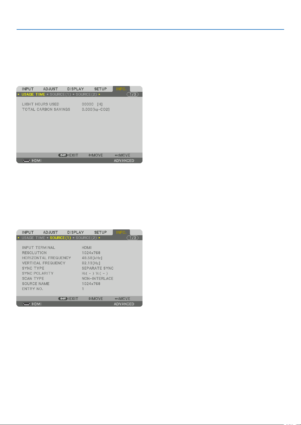
137
5. Using On-Screen Menu
❽ Menu Descriptions & Functions [INFO.]
Displaysthestatusofthecurrentsignalandlightmoduleusage.Thisitemhasninepages.Theinformationincluded
isasfollows:
TIP:PressingtheHELPbuttonontheremotecontrolwillshowthe[INFO.]menuitems.
[USAGE TIME]
[LIGHTHOURSUSED](H)
[TOTALCARBONSAVINGS](kg-CO2)
• [TOTALCARBONSAVINGS]
Thisdisplaystheestimatedcarbonsavinginformationinkg.Thecarbonfootprintfactorinthecarbonsavingcal-
culationisbasedontheOECD(2008Edition).(→page41)
[SOURCE(1)]
INPUTTERMINAL RESOLUTION
HORIZONTALFREQUENCY VERTICAL FREQUENCY
SYNCTYPE SYNC POLARITY
SCANTYPE SOURCE NAME
ENTRYNO.
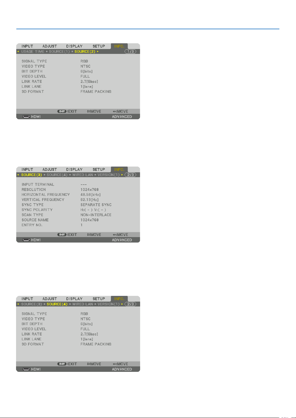
138
5. Using On-Screen Menu
[SOURCE(2)]
SIGNALTYPE VIDEOTYPE
BITDEPTH VIDEO LEVEL
LINKRATE LINKLANE
3DFORMAT
[SOURCE(3)]
INPUTTERMINAL RESOLUTION
HORIZONTALFREQUENCY VERTICAL FREQUENCY
SYNCTYPE SYNC POLARITY
SCANTYPE SOURCE NAME
ENTRYNO.
[SOURCE(4)]
SIGNALTYPE VIDEOTYPE
BITDEPTH VIDEO LEVEL
LINKRATE LINKLANE
3DFORMAT
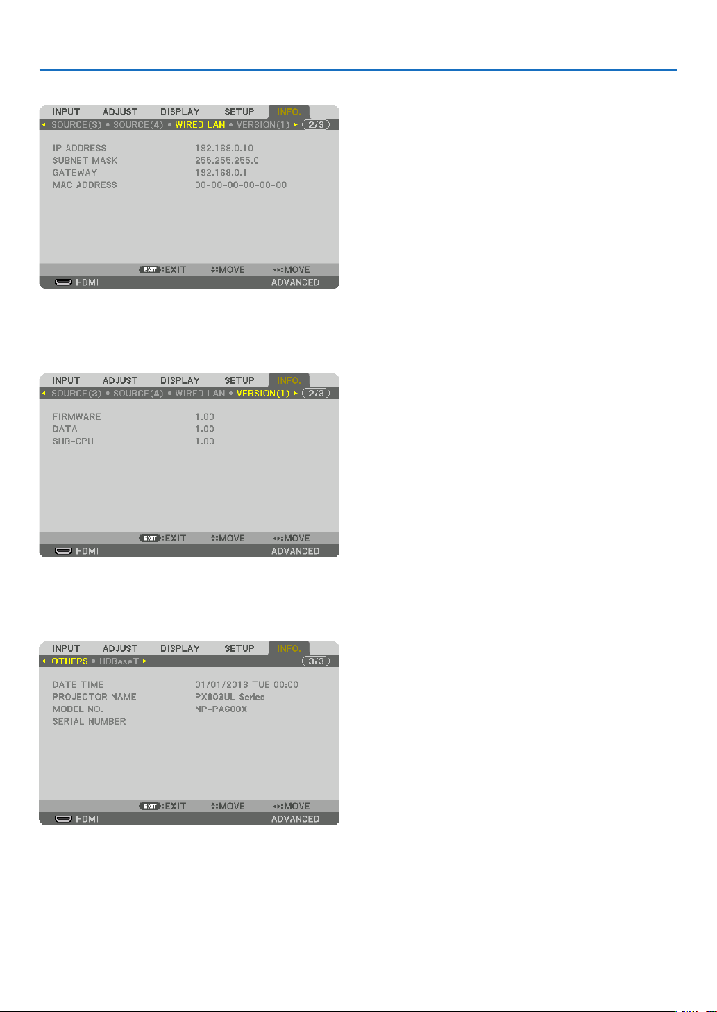
139
5. Using On-Screen Menu
[WIRED LAN]
IPADDRESS SUBNETMASK
GATEWAY MACADDRESS
[VERSION(1)]
FIRMWARE DATA
SUB-CPU
[OTHERS]
DATETIME PROJECTORNAME
MODELNO. SERIAL NUMBER
CONTROLID(when[CONTROLID]isset)

140
5. Using On-Screen Menu
[HDBaseT]
SIGNALQUALITY OPERATIONMODE
LINKSTATUS HDMISTATUS
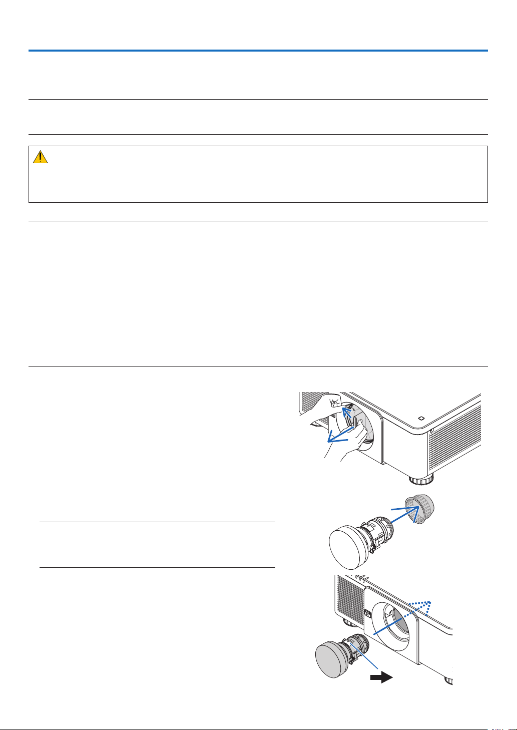
141
❶ Mounting a lens (sold separately)
Thisprojectorcanbeusedwith8kindsofoptionallenses(soldseparately).ThedescriptionsherearefortheNP18ZL
(standardzoom)lens.Mountotherlensesinthesamemanner.Seepage182forlensoptions.
Important:
• Forusingthefollowingoptionlenses,besuretocarryout[LENSCALIBRATION]afterreplacingthelens.(→ page 18, 118)
NP16FL,NP17ZL,NP18ZL,NP19ZL,NP20ZL,NP21ZL,NP31ZL
WARNING:
(1)Turnoffthepowerandwaitforthecoolingfantostop,(2)turnoffthemainpowerswitch,(3)disconnectthe
powercordandwaitfortheunittocoolbeforemountingorremovingthelens.Failuretodosocanresultineye
injury,electricshock,orburninjuries.
NOTE:
• Theprojectorandlensesaremadeofprecisionparts.Donotsubjectthemtoshockorexcessiveforces.
• Removetheseparatelysoldlenswhenmovingtheprojector.Ifnot,thelenscouldbesubjecttoshockwhiletheprojectorisbeing
moved,damagingthelensandthelensshiftmechanism.
• Whendismountingthelensfromtheprojector,returnthelenspositiontothehomepositionbeforeturningoffthepower.Failure
todosomaypreventthelensfrombeingmountedordismountedbecauseofnarrowspacebetweentheprojectorandthelens.
• Nevertouchthelenssurfacewhiletheprojectorisoperating.
• Beverycarefulnottoletdirt,grease,etc.,onthelenssurfaceandnottoscratchthelenssurface.
• Performtheseoperationsonaatsurfaceoverapieceofcloth,etc.,topreventthelensfromgettingscratched.
• Whenleavingthelensofftheprojectorforlongperiodsoftime,mountthedustcapontheprojectortopreventdustordirtfrom
gettinginside.Ifthelensremainsdetachedfromtheprojectorforlongperiodsoftime,dustmaycollectwithintheopticalunit
anddamagethelens,causingdeteriorationofprojectedimage.
• Lensesotherthanspeciedinthismanualcannotbemountedonthisprojector.
Mounting the lens
1. Removethedustcapfromtheprojector.
Pushthetongueatthetopleftoutwardandpulltheknobat
thecenterofthecap.
2. Removethelenscaponthebackofthelens.
• ThelensNP18ZLisusedasanexample.
NOTE:
• Makesuretoremovethelenscapattheunitbackside.Ifthelens
unitwiththelenscapremainingonisinstalledontheprojector,
itmaycauseofmalfunction.
3. Hold the lens unit aligning the labelled arrow on the unit
coming top and insert the unit to the projector.
Insertthelensslowlyallthewayin,keepingthepositioning
slitatthesameangle.
Arrowmark
6. Connecting to Other Equipment
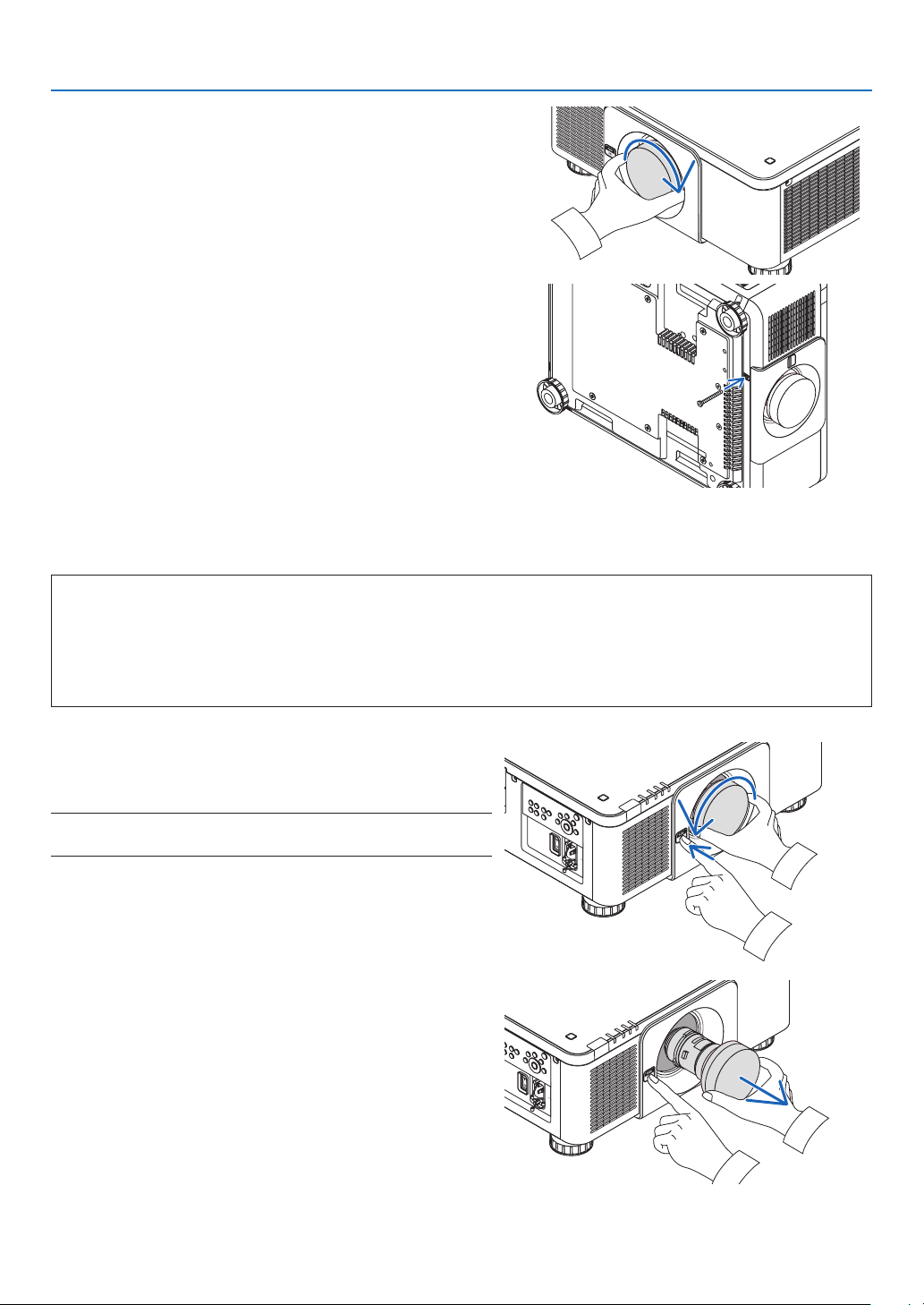
142
6. Installation and Connections
4. Turn the lens unit rightward until click is heard.
Thelensisnowfastenedontotheprojector.
TIP:Mountingthelenstheftpreventionscrew
Fastenthelenstheftpreventionscrewincludedwiththeprojectorto
thebottomoftheprojectorsothatthelenscannotberemovedeasily.
Removing the lens
Beforeremovingthelens:
1. Turn on the projector and display an image. (→ page 17)
2. Press and hold the SHUTTER/HOME POSITION button over 2 seconds.
Thelenspositionwillbemovedtothehomeposition.
3. Turnoffthemainpowerswitch,andthenunplugthepowercord.
4. Wait until the projector cabinet is cool enough to handle.
1. While pressing the LENS release button on the projec-
tor’sfrontpanelfullyin,turnthelenscounterclockwise.
Thelenscomesoff.
NOTE:IfthelenscannotberemovedwhentheLENSreleasebuttonis
pressed,checkwhetherthelenstheftpreventionscrewismounted.
2. Afterslowlypullingthelensofftheprojector,releasethe
LENS release button.
- Afterremovingthelens,mountthelenscaps(frontand
back)includedwiththelensbeforestoringthelens.
- Ifnolensisgoingtobemountedontheprojector,mount
thedustcapincludedwiththeprojector.
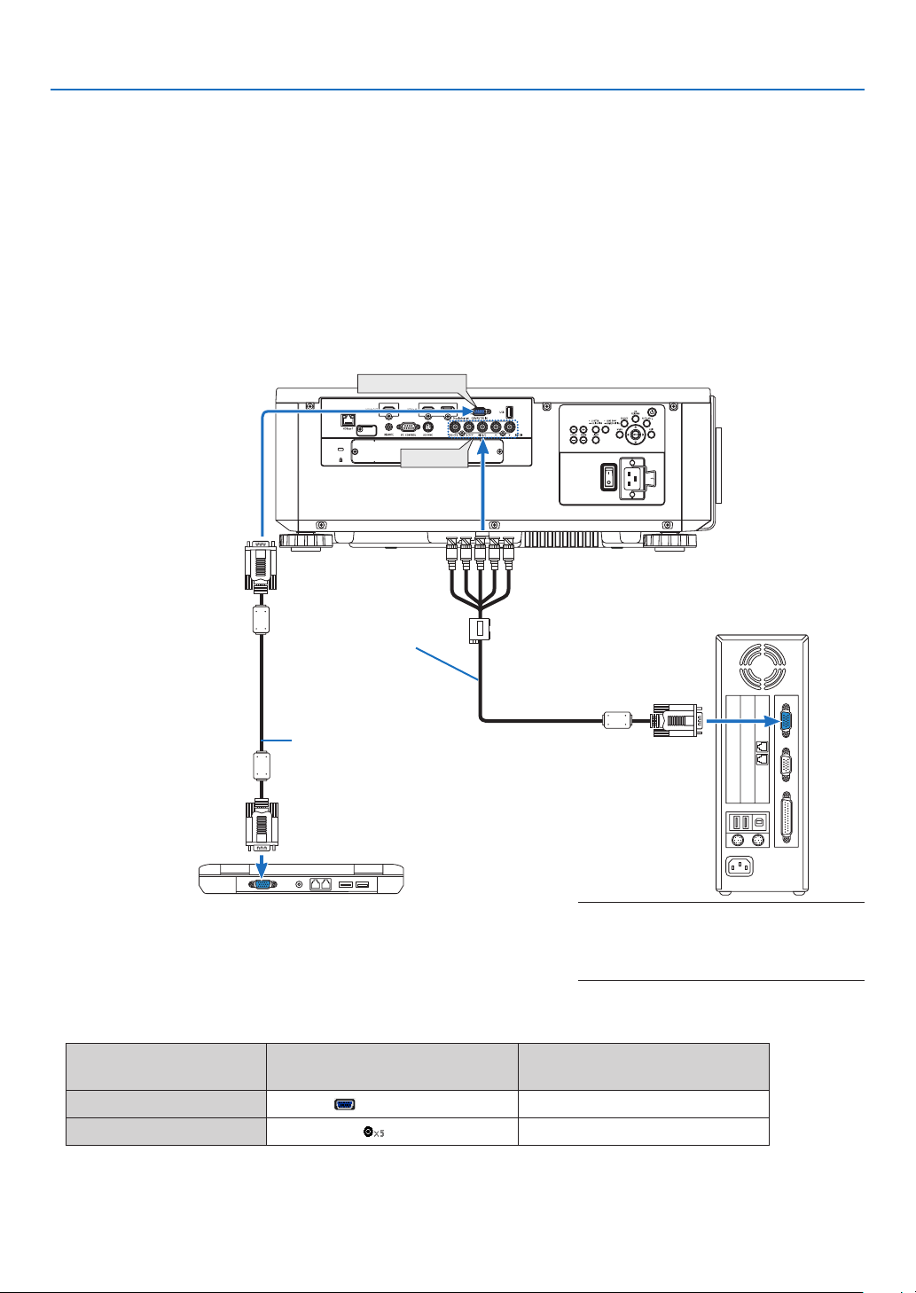
143
6. Installation and Connections
❷ Making Connections
Acomputercable,BNCcable(5-coretype),HDMIcable,oraDisplayPortcablecanbeusedtoconnecttoacomputer.
Theconnectioncableisnotenclosedwiththeprojector.Pleasegetreadyasuitablecablefortheconnection.
Analog RGB signal connection
• Connectthecomputercabletothedisplayoutputterminal(miniD-sub15pin)onthecomputerandtheCOMPUTER
INterminalontheprojector.Pleaseuseacomputercableattachedwithaferritecore.
• Whenconnectingthedisplayoutputterminal(miniD-sub15pin)onthecomputertotheBNCinputterminal,use
aconversioncabletoconverttheBNCcable(5core)toaminiD-sub15pincable.
• Selectthesourcenameforitsappropriateinputterminalafterturningontheprojector.
Inputterminal
SOURCEbuttonontheprojector
cabinet
Buttonontheremotecontrol
COMPUTERIN COMPUTER COMPUTER1
BNC BNC COMPUTER2
COMPUTER IN
BNC IN
Computercable(soldcommercially)
RGB-to-BNCcable
(notsupplied)
NOTE:Pleasechecktheoperatingmanualof
thecomputerasthename,positionanddirec-
tionoftheterminalmaydifferdependingon
thecomputer.
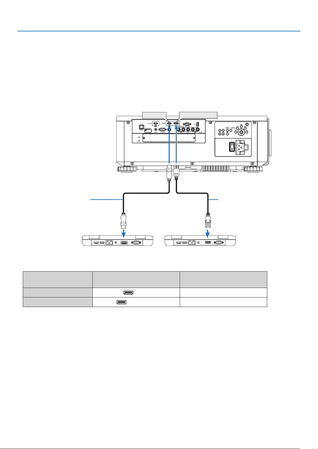
144
6. Installation and Connections
Digital RGB signal connection
• ConnectacommerciallyavailableHDMIcablebetweenthecomputer’sHDMIoutputterminalandtheprojector’s
HDMIINterminal.
• ConnectacommerciallyavailableDisplayPortcablebetweenthecomputer’sDisplayPortoutputterminalandthe
projector’sDisplayPortINterminal.
• Selectthesourcenameforitsappropriateinputterminalafterturningontheprojector.
Inputterminal
SOURCEbuttonontheprojector
cabinet
Buttonontheremotecontrol
HDMIIN HDMI HDMI
DisplayPortIN DisplayPort DisplayPort
DisplayPort IN
HDMI IN
HDMIcable(notsupplied) DisplayPortcable(notsupplied)

145
6. Installation and Connections
CautionswhenconnectinganHDMIcable
• UseacertiedHighSpeedHDMI
®
CableorHighSpeedHDMI
®
CablewithEthernet.
Cautions when connecting a DisplayPort cable
• UseacertiedDisplayPortcable.
• Dependingonthecomputer,sometimemayberequireduntiltheimageisdisplayed.
• SomeDisplayPortcables(commerciallyavailable)havelocks.
• Todisconnectthecable,pressthebuttononthetopofthecable’sterminal,thenpullthecableout.
• PowercanbesuppliedtotheconnectingdevicefromtheDisplayPortINterminal(maximumof1.65W).However,
powerwillnotbesuppliedtothecomputer.
• WhensignalsfromadevicethatusesasignalconverteradapterareconnectedtotheDisplayPortINterminal,in
somecasestheimagemaynotbedisplayed.
• WhentheHDMIoutputofacomputerisconnectedtotheDisplayPortINterminal,useaconverter(commercially
available).
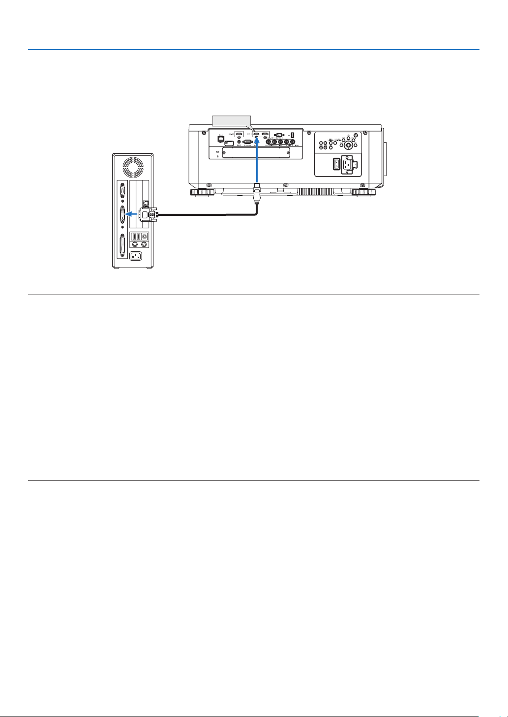
146
6. Installation and Connections
CautionswhenusingaDVIsignal
• WhenthecomputerhasaDVIoutputterminal,useacommerciallyavailableconvertercabletoconnectthecom-
putertotheprojector’sHDMIINterminal(onlydigitalvideosignalscanbeinput).
HDMI IN
NOTE:WhenViewingaDVIDigitalSignal
• Turnoffthepowerofthecomputerandprojectorbeforeconnectingdevices.
• Whenavideodeckisconnectedviaascanconverter,etc.,thedisplaymaynotbecorrectduringfast-forwardingandrewinding.
• UseaDVI-to-HDMIcablecompliantwithDDWG(DigitalDisplayWorkingGroup)DVI(DigitalVisualInterface)revision1.0stan-
dard.Thecableshouldbewithin197"/5mlong.
• TurnofftheprojectorandthePCbeforeconnectingtheDVI-to-HDMIcable.
• ToprojectaDVIdigitalsignal:Connectthecables,turntheprojectoron,thenselecttheHDMI.Finally,turnonyourPC.
Failuretodosomaynotactivatethedigitaloutputofthegraphicscardresultinginnopicturebeingdisplayed.Shouldthishappen,
restartyourPC.
• SomegraphicscardshavebothanalogRGB(15-pinD-Sub)andDVI(orDFP)outputs.Useofthe15-pinD-Subterminalmay
resultinnopicturebeingdisplayedfromthedigitaloutputofthegraphicscard.
• DonotdisconnecttheDVI-to-HDMIcablewhiletheprojectorisrunning.Ifthesignalcablehasbeendisconnectedandthen
reconnected,animagemaynotbecorrectlydisplayed.Shouldthishappen,restartyourPC.
• TheCOMPUTERINterminalssupportWindowsPlugandPlay.TheBNCinputterminaldoesnotsupportWindowsPlugandPlay.
• AMacsignaladapter(commerciallyavailable)mayberequiredtoconnectaMaccomputer.
ToconnectaMaccomputerequippedwithaMiniDisplayPorttotheprojector,useacommerciallyavailableMiniDisplayPort→
DisplayPortconvertercable.
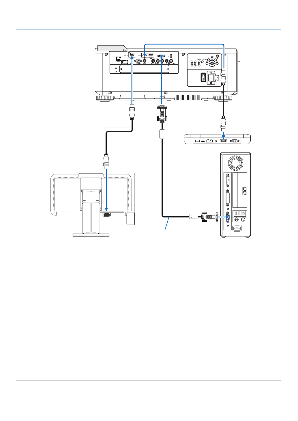
147
6. Installation and Connections
HDMI IN
HDMI OUT
Connecting an External Monitor
Youcanconnectaseparate,externalmonitortoyourprojectortosimultaneouslyviewonamonitorthecomputer
analogimageyou’reprojecting.
• BNC(CV)componentvideosignalsandBNC(Y/C)S-videosignalswillnotbeoutput.
• PleaserefertoPage68whendisplayingthePIP/PBPscreen.
NOTE:
• WhenoutputtingHDMIsignals,turnonthepowerofthevideodeviceontheoutputsideandkeepitconnectedbeforeinputting
videosignalsintothisdevice.TheHDMIOUTterminalsoftheprojectorareequippedwithrepeaterfunctions.Whenadeviceis
connectedtotheHDMIOUTterminal,theresolutionoftheoutputsignalislimitedbytheresolutionsupportedbytheconnected
device.
• InthecaseoftheHDMIOUTterminaloftheprojector,thetheoreticalnumberofunitsthatcanbeconnectedinaseriesisseven.
Themaximumnumberofunitsthatcanbeconnectedmaybereducedbytheexternalenvironmentandqualityofthesignaland
cable,etc.ThenumberofunitsthatcanbeconnectedmaydifferdependingontheHDCPversion,restrictiononthenumberof
HDCPrepeatersinthesourcedeviceandthequalityofthecable.Theoverallsystemneedstobecheckedinadvancewhenbuild-
ingasystem.
• Whenthe[STANDBYMODE]issetto[NORMAL],videowillnotbeoutputiftheprojectorgoesintothestandbymode.Setthe
modeto[NETWORKSTANDBY],turnonthepowerofthetransmissiondeviceandkeepitinaconnectedstate.
• Whenthe[STANDBYMODE]ofthisdeviceissetto[NORMAL],HDMIsignalswillnotbeoutput.TooutputHDMIsignals,setthe
[STANDBYMODE]to[NETWORKSTANDBY],turnonthepowersupplyofthetransmissiondeviceandkeepitconnected.
• HDMIrepeaterfunctionwillnotbefunctionedifswitchingterminalsandputtingin/pullingouttheHDMIcableisperformedon
the 2nd projector and after.
Computercable(VGA)(notsupplied)
HDMIcable(notsupplied)
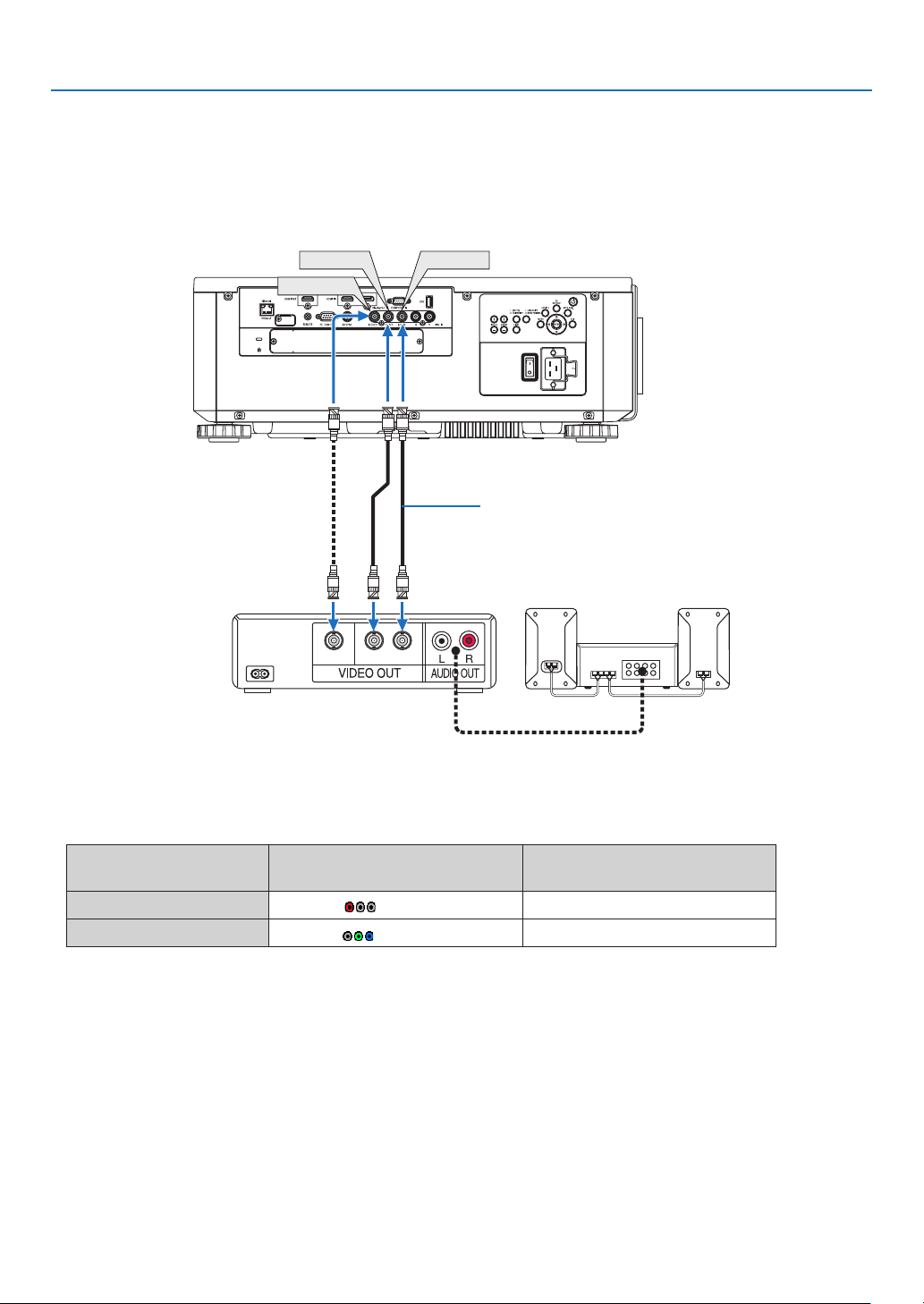
148
6. Installation and Connections
Connecting Your Blu-ray Player or Other AV Equipment
Componentvideosignal/S-videosignalconnection
• Selectthesourcenameforitsappropriateinputterminalafterturningontheprojector.
Inputterminal
SOURCEbuttonontheprojector
cabinet
Buttonontheremotecontrol
BNC(CV) BNC(CV) VIDEO
BNC(Y/C)
BNC(Y/C) S-VIDEO
CV YC
BNC(CV)
BNC(Y)
BNC(C)
BNCcable(notsupplied)
Audioequipment
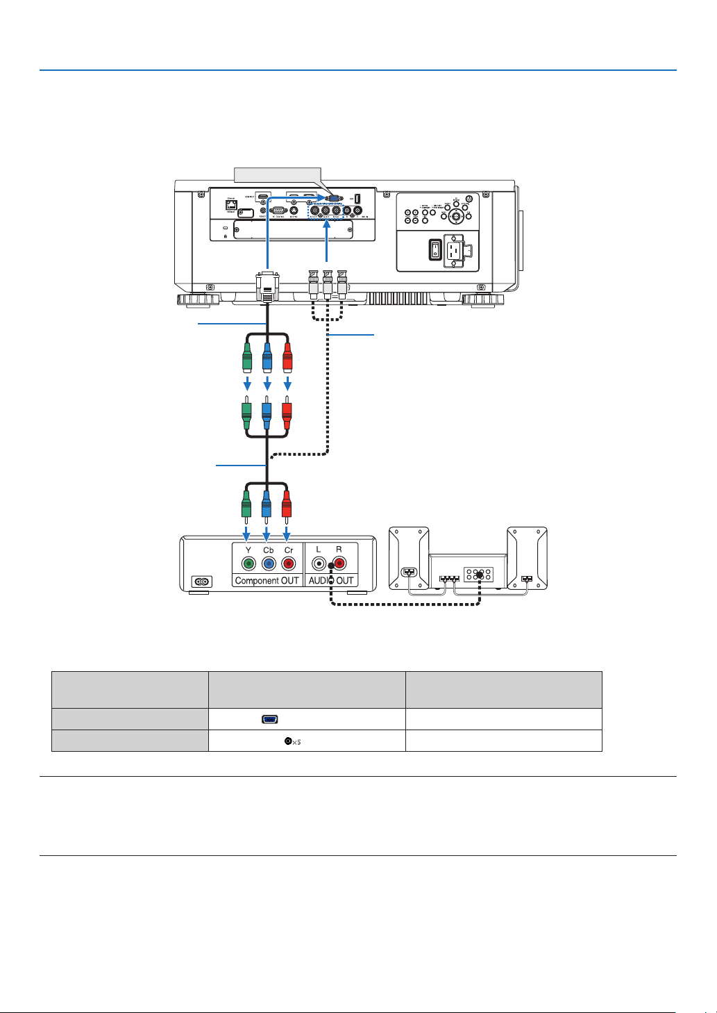
149
6. Installation and Connections
Connecting Component Input
• Selectthesourcenameforitsappropriateinputterminalafterturningontheprojector.
Inputterminal
SOURCEbuttonontheprojector
cabinet
Buttonontheremotecontrol
COMPUTERIN COMPUTER COMPUTER1
BNC BNC COMPUTER2
NOTE:
• Whenthesignalformatissetto[AUTO](defaultfactorysettingwhenshipped),thecomputersignalandcomponentsignalare
automaticallydistinguished and switched. If thesignalscannotbedistinguished, select [COMPONENT] under [ADJUST]→
[VIDEO]→[SIGNALTYPE]intheon-screenmenuoftheprojector.
• ToconnecttoavideodevicewithaDterminal,usethesoldseparatelyDterminalconverteradapter(modelADP-DT1E).
COMPUTER IN
15-pin-to-RCA(female)×3
cableadapter(ADP-CV1E)
BNC(male)-to-RCA(male)conversion
cable×3(soldcommercially)
ComponentvideoRCA×3cable
(notsupplied)
Blu-rayplayer
AudioEquipment
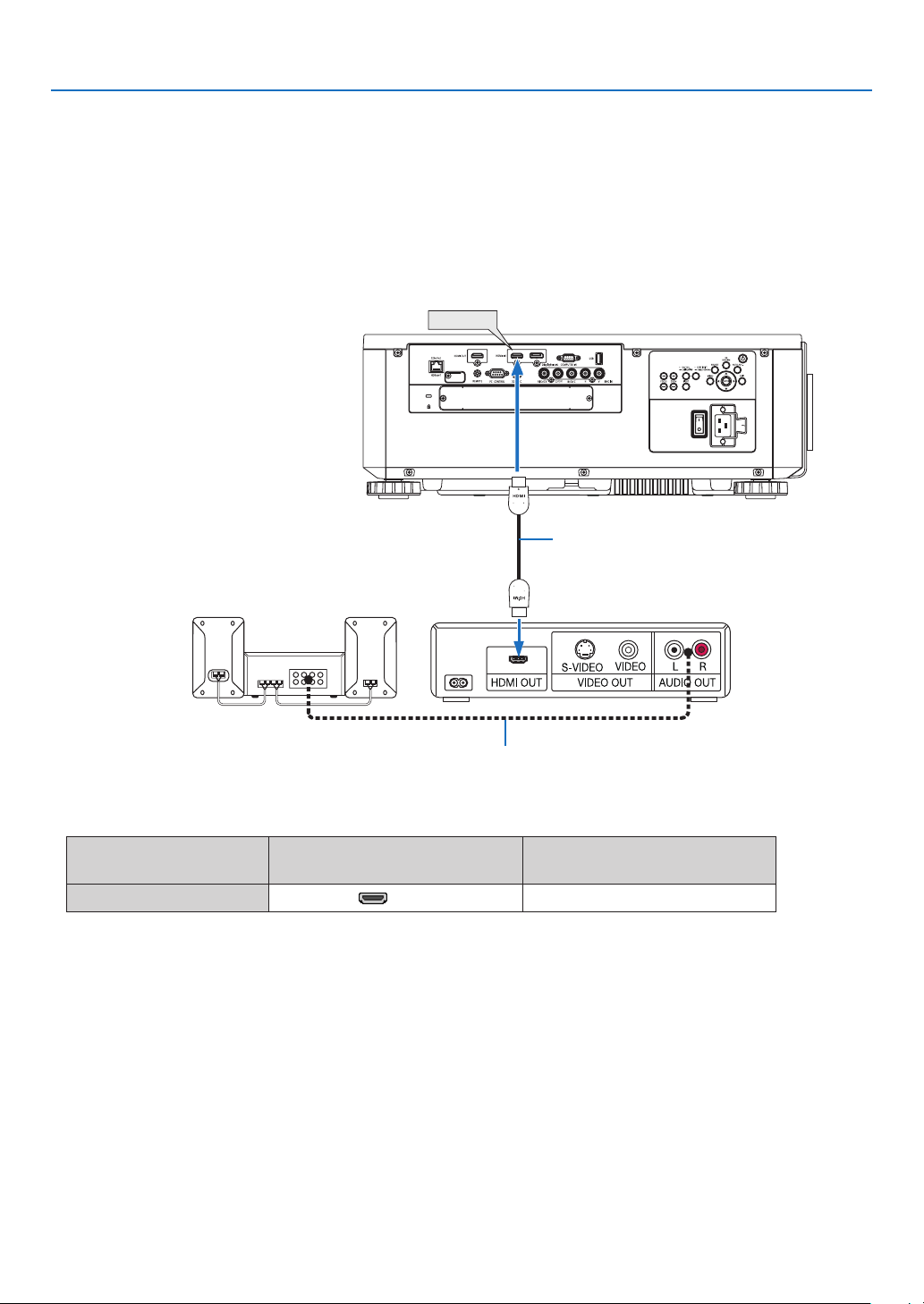
150
6. Installation and Connections
Connecting HDMI Input
YoucanconnecttheHDMIoutputofyourBlu-rayplayer,harddiskplayer,ornotebooktypePCtotheHDMIINterminal
ofyourprojector.
Inputterminal
SOURCEbuttonontheprojector
cabinet
Buttonontheremotecontrol
HDMIIN HDMI HDMI
TIP:ForusersofaudiovideoequipmentwithanHDMIterminal:
Select“Enhanced”ratherthan“Normal”ifHDMIoutputisswitchablebetween“Enhanced”and“Normal”.
Thiswillprovideimprovedimagecontrastandmoredetaileddarkareas.
Formoreinformationonsettings,refertotheinstructionmanualoftheaudiovideoequipmenttobeconnected.
• WhenconnectingtheHDMIINterminaloftheprojectortotheBlu-rayplayer,theprojector’svideolevelcanbe
madesettingsinaccordancewiththeBlu-rayplayer’svideolevel.Inthemenuselect[ADJUST]→[VIDEO]→
[VIDEOLEVEL]andmakenecessarysettings.
HDMI IN
Audiocable(notsupplied)
HDMIcable(notsupplied)
UseHighSpeedHDMI
®
Cable.
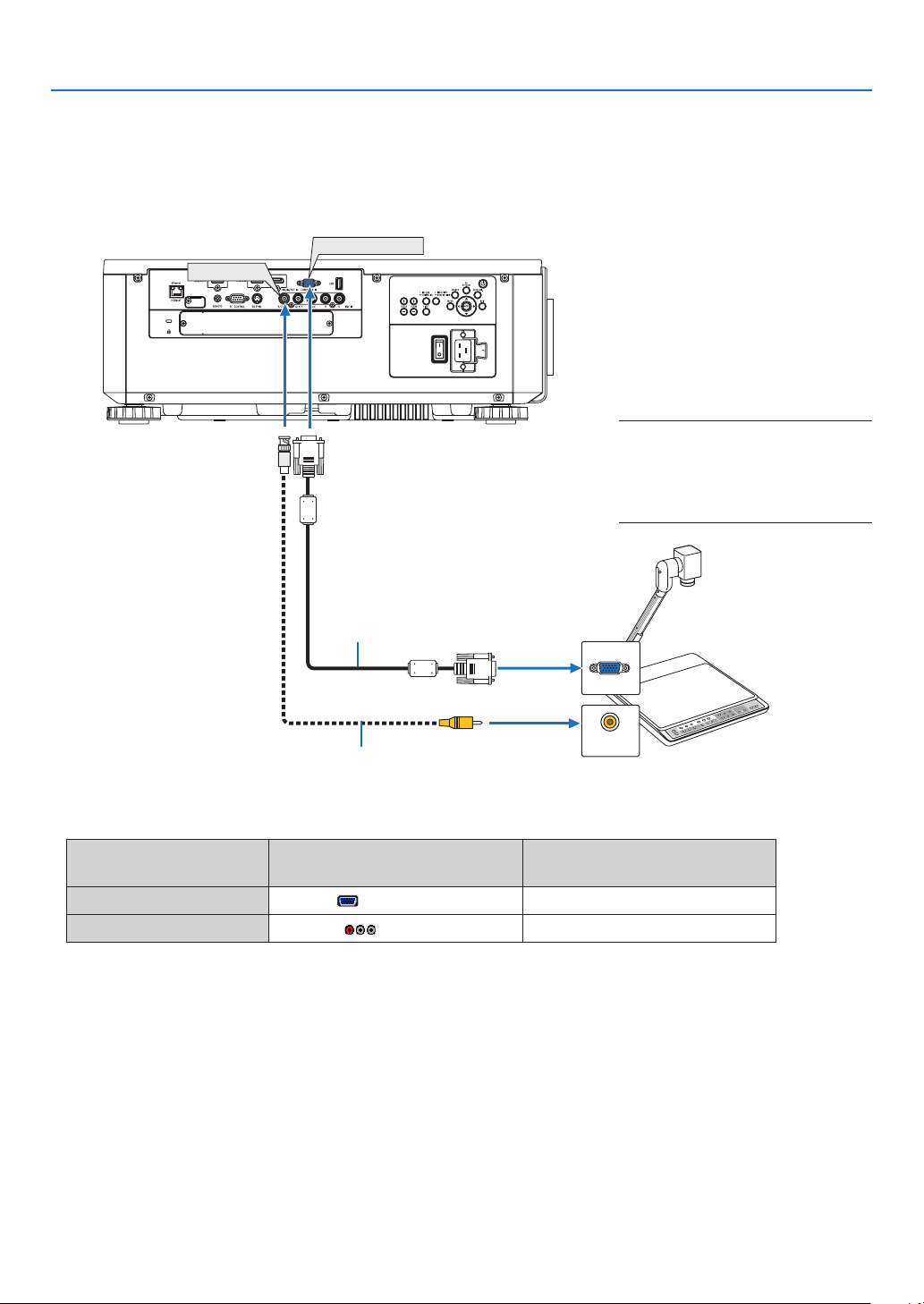
151
6. Installation and Connections
Connecting a document camera
Youcanconnectadocumentcameraandprojectprinteddocuments,etc.
• Selectthesourcenameforitsappropriateinputterminalafterturningontheprojector.
Inputterminal
SOURCEbuttonontheprojector
cabinet
Buttonontheremotecontrol
COMPUTERIN COMPUTER COMPUTER1
BNC(CV) BNC(CV) VIDEO
BNC
(
CV
)
COMPUTER IN
VIDEO
NOTE:
• Name, position, and direction of ter-
minalsarevarydependingoncamera
model.Pleasecheckuser’smanualof
yourcamerafordetails.
BNC(male)andRCA(male)conver-
sioncable(notsupplied)
Computercable(notsupplied)
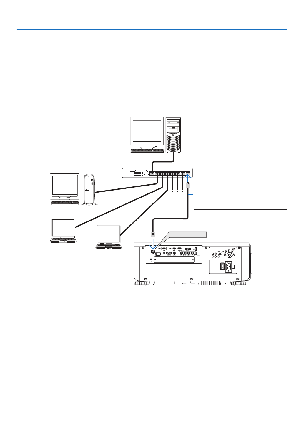
152
6. Installation and Connections
Connecting to a Wired LAN
TheprojectorcomesstandardwithaEthernet/HDBaseTport(RJ-45)whichprovidesaLANconnectionusingaLAN
cable.
TouseaLANconnection,youarerequiredtosettheLANontheprojectormenu.Select[SETUP]→[NETWORK
SETTINGS]→[WIREDLAN].(→page127).
Example of LAN connection
ExampleofwiredLANconnection
Ethernet/HDBaseT
Server
Hub
LANcable(notsupplied)
NOTE:UseaCategory5orhigherLANcable.
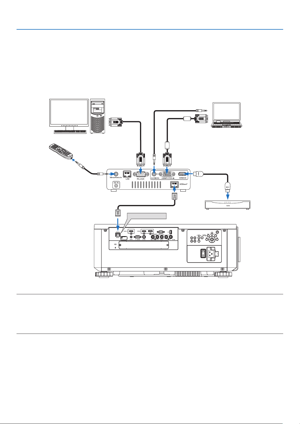
153
6. Installation and Connections
Connecting to a HDBaseT transmission device (sold commercially)
HDBaseTisaconnectionstandardforhomeappliancesthatisestablishedbytheHDBaseTAlliance.
UseaLANcablesoldcommerciallytoconnecttheEthernet/HDBaseTportoftheprojector(RJ-45)toaHDBaseT
transmissiondevicesoldcommercially.
TheEthernet/HDBaseTportoftheprojectorsupportsHDMIsignals(HDCP)fromtransmissiondevices,controlsignals
fromexternaldevices(serial,LAN)andremotecontrolsignals(IRcommands).
Connection example
Ethernet/HDBaseT
Computer(forcontroluse)
Computer(foroutputuse)
Exampleofatransmissiondevice
Remotecontrol
HDMIoutputvideodevice
NOTE:
• Pleaseuseashieldedtwistedpair(STP)cableofCategory5eorhigherfortheLANcable(soldcommercially).
• ThemaximumtransmissiondistanceovertheLANcableis100m.(themaximumdistanceis70mfora4Ksignal)
• Pleasedonotuseothertransmissionequipmentbetweentheprojectorandtransmissionequipment.Thepicturequalitymaybe
deteriorated as a result.
• ThisprojectorisnotguaranteedtoworkwithallHDBaseTtransmissiondevicessoldcommercially.
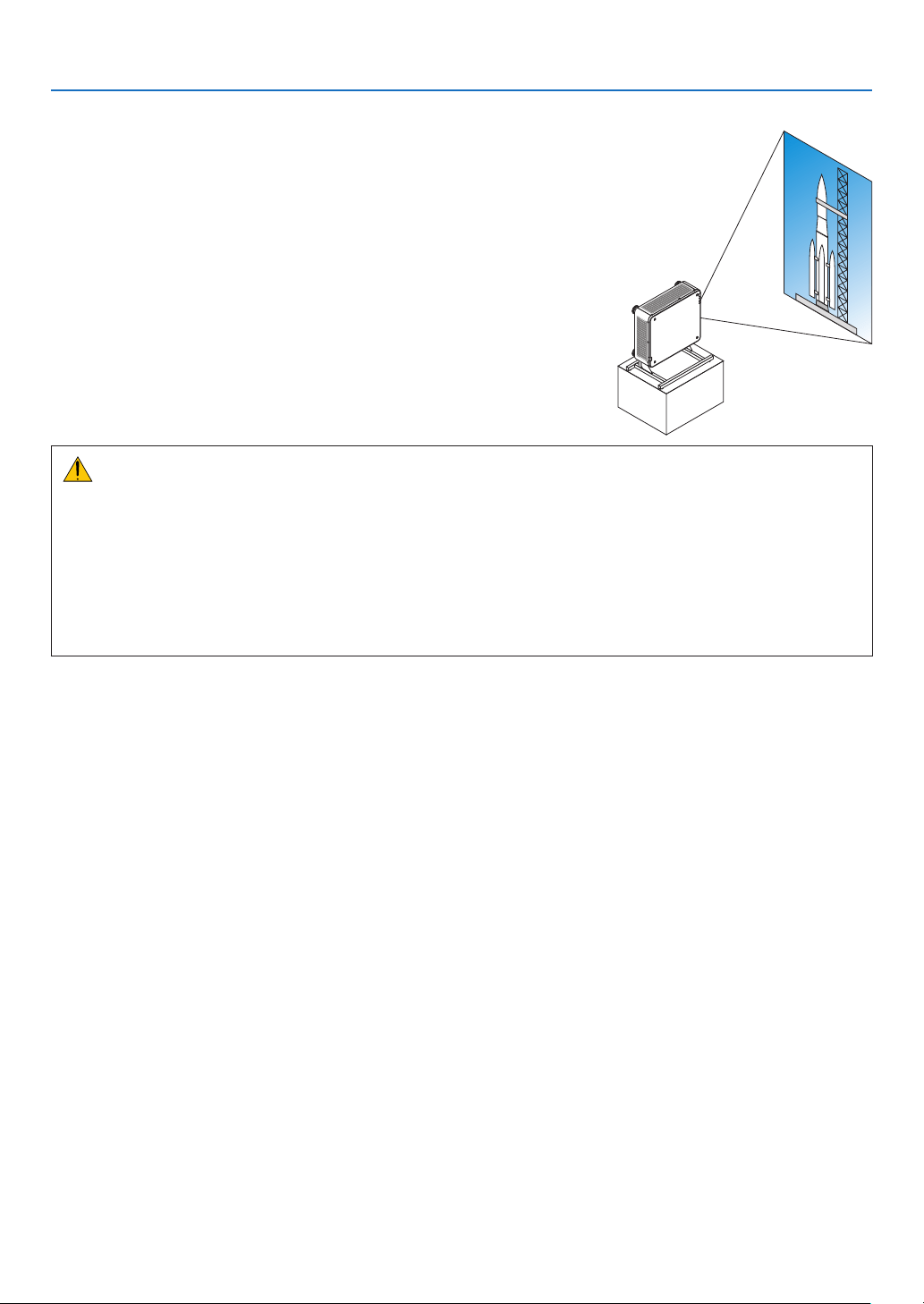
154
6. Installation and Connections
Portrait projection (vertical orientation)
Thisprojectorcanbeinstalledverticallytodisplaycomputerimagesin
portraitorientation.
Precautions during installation
• Pleasedonotinstalltheprojectorinaverticalorientationontopoftheoorortableonitsown.Ifnot,thepro-
jectormayfallover,resultingininjury,damageormalfunction.
• Astandforsupportingtheprojectorneedstobemadeforthispurposetokeepintakeairowsecurelyand
preventivemeasureoffallingover.Thestandmustbedesignedsuchthatthecenterofgravityoftheprojector
islocatedwellwithinthelegsofthestand.Ifnot,theprojectormayfalloverandresultininjury,damageand
malfunction.
• Iftheprojectorisinstalledonwhichtheintakeventfacingdown,opticalpartlifemaybeshorten.
155
6. Installation and Connections
Design and manufacturing conditions for the stand
Pleasehireaninstallationserviceprovider(forafee)forthedesignandmanufactureofacustomizedstandtobeused
forportraitprojection.Pleaseensurethatthedesigncomplieswiththefollowingconditions:
• Thereare3ventilationholesatthebottomoftheprojector.Theseholesshouldremainunobstructed.
• Usethe6screwholesatthebackoftheprojectortosecureittothestand.
Screwholecenterdimension:300×300(pitch=150)mm
Screwholedimensionontheprojector:M4withthemaximumdepth16mm
4ofthelegscanbeunscrewedforremoval.
• Horizontaladjustmentmechanism(forexample,boltsandnutsin4places)
• Pleasedesignthestandsothatitdoesnoteasilytoppleover.
Reference drawings
* Thedrawingshowingthedimensionalrequirementsisnotanactualstanddesigndrawing.
300
150 150124.5
[Side View][Front View]
(Unit: mm)
Horizontal adjuster
Air exhaust
6 - M4 bolt
Air intakeAir intake
Air intake
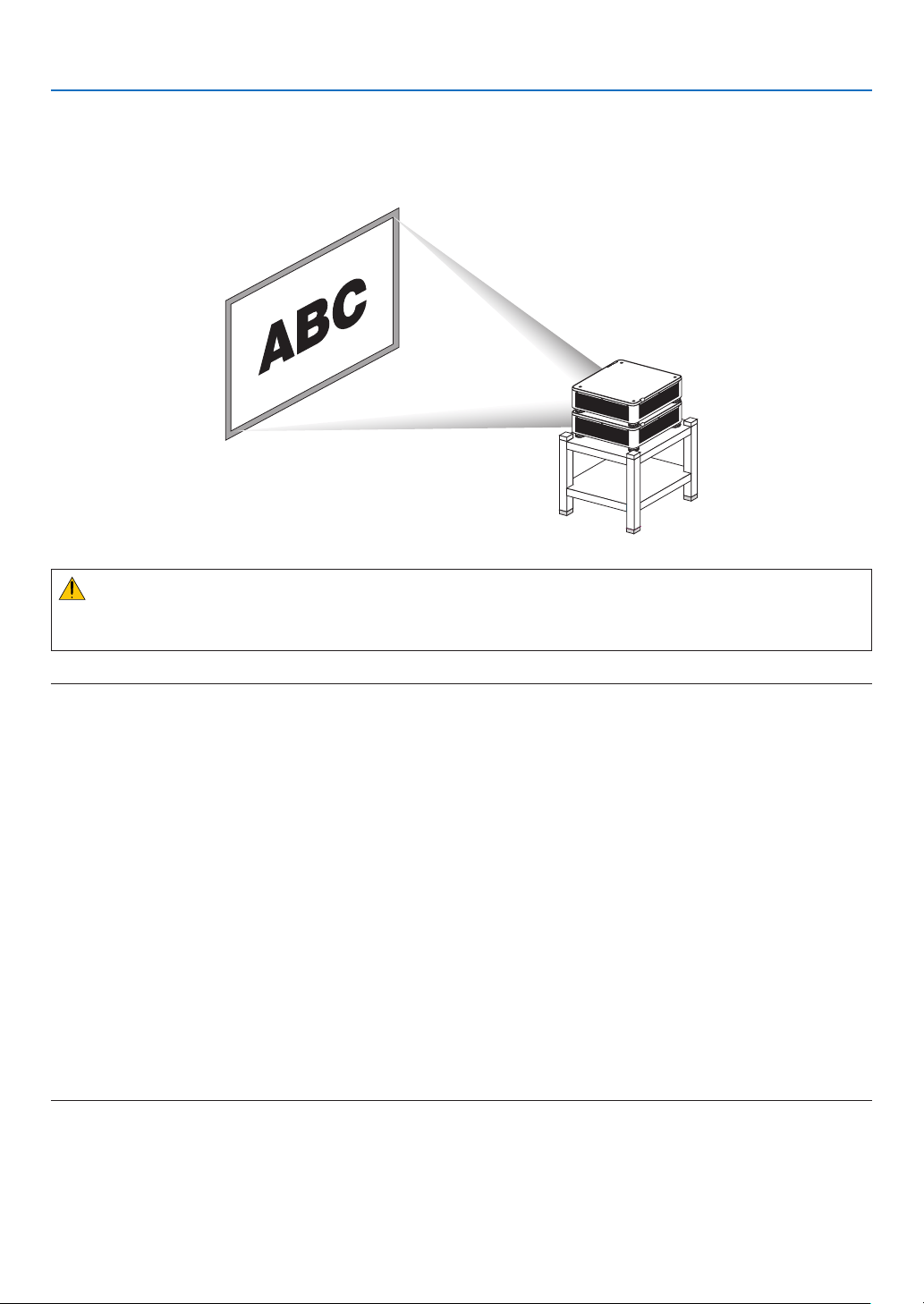
156
6. Installation and Connections
Stacking projectors
Theprojectedimagebrightnesscanbedoubledbygravitystackinguptotwoprojectorswithoutexternalsupport.This
iscalled“StackingProjection”.
2projectorscanbestackedontopofeachotherfor“Stacking”setup.
CAUTION:
Aminimumoftwopersonsarerequiredtocarrytheprojector.Otherwisetheprojectormaytumbleordrop,causing
personalinjury.
NOTE:
• Projectorswithdifferentmodelnumberscannotbegravitystacked.
Optionallenseswiththesamemodelnumbersmustbeusedforstackingprojection.
• Forstackingprojectors,attachthesuppliedfourstackingholderstothetopofthelowerprojector.(→ nextpage)
• Itdoesnotsupportoverlayaccuracybystackedprojectors.Preciseimagesassmalltextsanddetailedgraphicscannotbeclearly
read or seen.
• Useacommerciallyavailabledistributionampliertoboththeprimary(upper)andthesecondary(lower)projectorstodistribute
signal to two outputs of the two projectors.
• Notesforstacking
- Askyourservicepersonforsettingupandadjustingprojectors.
- Setuptheprojectorsinaplaceorstructureinawaywithsufcientstrengthtosupportthecombinedweightofthetwoprojec-
tors.Thesingleprojectorwithalensweighsuptoapproximately31kg/68lbs.
- Topreventtheprojectorsfromfalling,fastentheminawaytowithstandearthquakes.
- Doublestackingwillcauseroomtemperaturetoincrease.Ventilatetheroomwell.
- Donotattempttostackprojectorsontheceiling.Gravitystackingcannotbedoneontheceiling.
- Warmuptheprojectorsforonehourbeforethedesiredprojectionisobtained.
- Makesurethatthepositionoftheupperprojectordoesnotexceeditsspecications.Whensettingupthetwoprojectors,
adjustable height range for the tilt foot on the upper projector is added to the total adjustable range.
- Setuptheprojectorssothattheprojectedimageshowsaslittlegeometricdistortionsaspossible.Thelensisdifferentin
geometricdistortionbetweenwide(+)andtele(−)forzoom.
- Adjustthehorizontallensshifttothelenscenter.
s
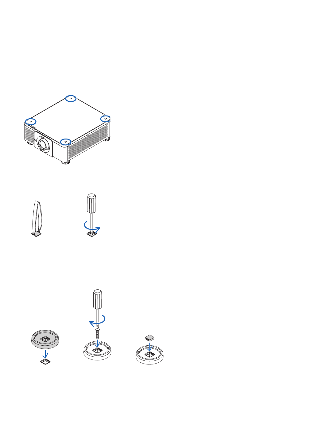
157
6. Installation and Connections
AttachingStackingHolders
Attachthreestackingholderstothreelocationsonthetopofthelowerprojector.
Preparation:
ToolsrequiredarePhillipsscrewdriver(plus-head)andfourstackingholderspackagedwiththeprojector.
Loosenthetiltfoot(fourlocations)oftheprojector.
1. Removerubbercapsandscrewsatfourlocations.
(1)Useyourtweezersornailtopinchandpulluptherubbercap.
(2)Removethescrewfromasquarehole.
(1) (2)
2. Attachthethreestackingholdersatfourlocations.
(1)Placeastackingholderinasquarehole.
(2)UsethescrewremovedatStep1toxthestackingholderinthesquarehole.
(3)PuttherubbercapremovedatStep1backintothesquarehole.
• Snapthetabsonbothoftherubbercapintotheslitsonbothsidesinthesquarehole.
(1) (2) (3)
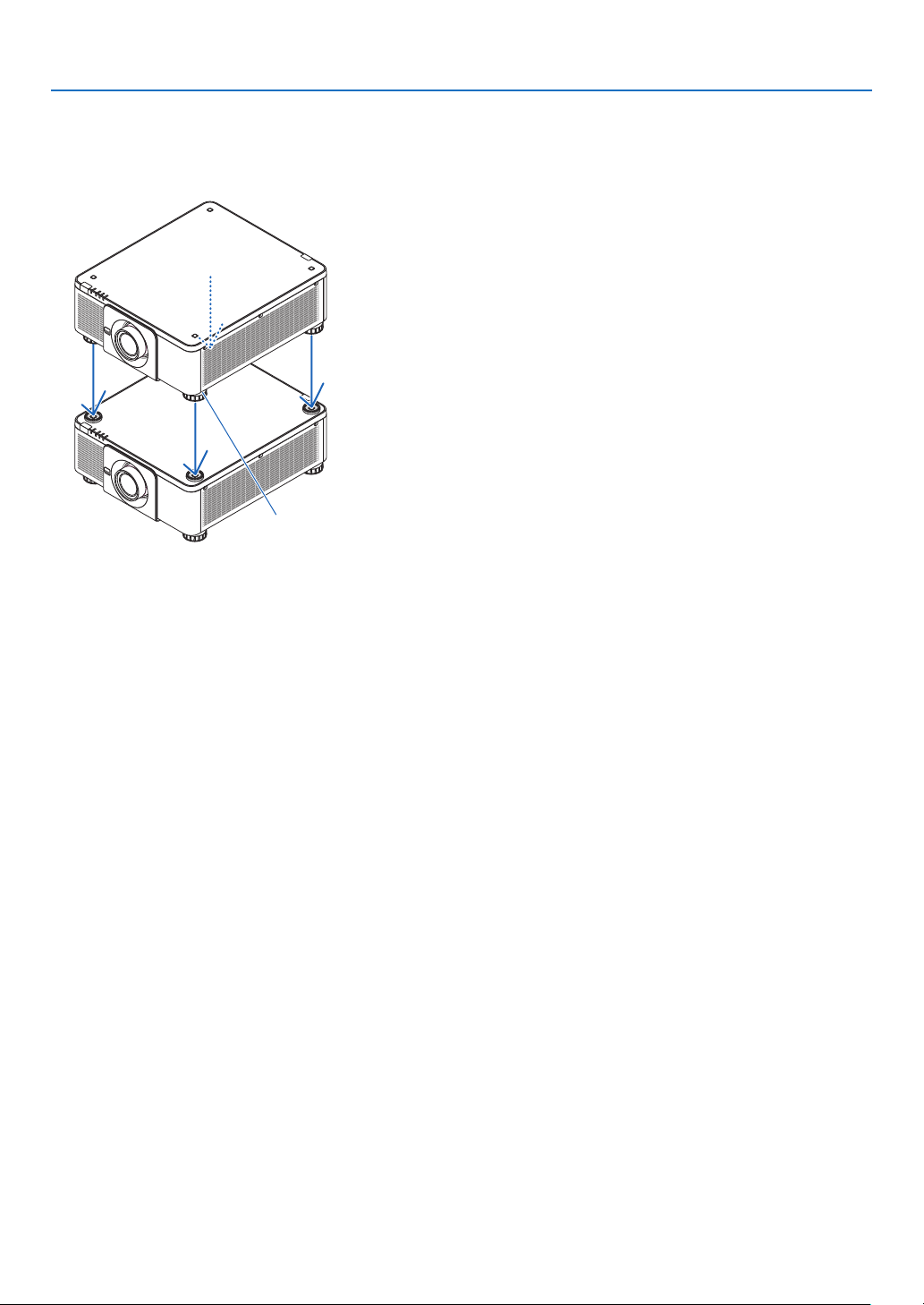
158
6. Installation and Connections
3. Putanotherprojectorontherstprojector.
Puteachtiltfootoftheupperprojectoronthestackingholders(fourlocations).
• Eachtiltfoothasarubber.Placeeachtiltfootrubberonstackingholders(fourlocations).
Footrubber
TIP:
• Toremovethestackingholders,performtheabovestepsinreverseorder.
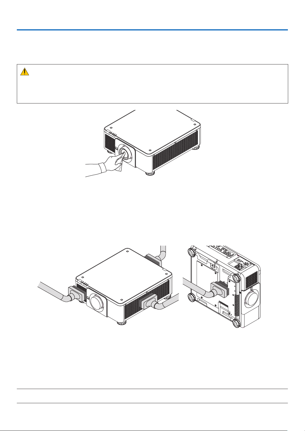
159
7. Maintenance
❶ Cleaning the Lens
• Turnofftheprojectorbeforecleaning.
• Useablowerorlenspapertocleanthelens,andbecarefulnottoscratchormarthelens.
WARNING
• Pleasedonotuseaspraycontainingammablegastoremovedustattachedtothelens,etc.Doingsomay
resultinres.
• Donotlookintothelenswhiletheprojectorison.Seriousdamagetoyoureyescouldresult.
❷ Cleaning the Cabinet
Turnofftheprojector,andunplugtheprojectorbeforecleaning.
• Useadrysoftclothtowipedustoffthecabinet.
Ifheavilysoiled,useamilddetergent.
• Neverusestrongdetergentsorsolventssuchasalcoholorthinner.
• Whencleaningtheventilationslitsorthespeakerusingavacuumcleaner,donotforcethebrushofthevacuum
cleanerintotheslitsofthecabinet.
Vacuumthedustofftheventilationslits.
• Poorventilationcausedbydustaccumulationinventilationopenings(alsoatthebottomoftheprojector)canresult
inoverheatingandmalfunction.Theseareasshouldbecleanedregularly.
• Donotscratchorhitthecabinetwithyourngersoranyhardobjects
• Contactyourdealerforcleaningtheinsideoftheprojector.
NOTE:Donotapplyvolatileagentsuchasinsecticideonthecabinet,thelens,orthescreen.Donotleavearubberorvinylproduct
inprolongedcontactwithit.Otherwisethesurfacenishwillbedeterioratedorthecoatingmaybestrippedoff.

160
8. User Supportware
❶ Operating Environment for Software Included on CD-ROM
Names and Features of Bundled Software Programs
Nameofsoftwareprogram Features
VirtualRemoteTool
(Windowsonly)
Whenthecomputerandprojectorareconnectedusinganetwork(wiredLAN),
suchoperationsasturningtheprojector’spoweronandoffandswitchingthe
signalcanbeperformed.Itisalsopossibletosendanimagetotheprojector
andregisteritasthebackgroundlogo.Oncetheimageisregistered,itcanbe
lockedtopreventthelogofrombeingoverwritten.
PCControlUtilityPro4
PCControlUtilityPro5(forMac
OS)
Thisisasoftwareprogramusedtooperatetheprojectorfromthe computer
whenthecomputerandtheprojectorareconnectedwithLAN.(→page152)
• PCControlUtilityPro4canbeusedwithaserialconnection.
NOTE:
• ToconnecttheprojectortothenetworkbyusingtheVirtualRemoteTool,PCControlUtilityPro4,PCControlUtilityPro5,please
congurethesettingsof[SETUP]→[NETWORKSETTINGS]intheon-screenmenu(→ page 127).
Download service
Fortheupdateinformationaboutthesesoftwareprogramsandtheiroperatingenvironment,visitourwebsite:
URL:http://www.nec-display.com/dl/en/index.html
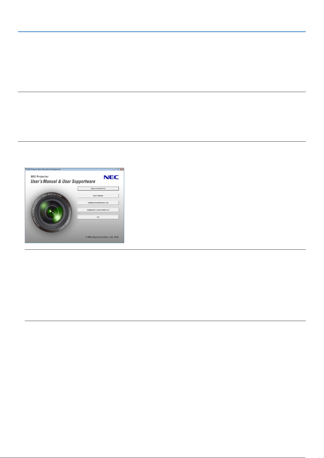
161
8. User Supportware
❷ Installing Software Program
Installation for Windows software
ThesoftwareprogramsexceptPCControlUtilityPro5supportWindows8.1,Windows8,Windows7,WindowsVista,
andWindowsXP.
NOTE:
• Toinstalloruninstalleachsoftwareprogram,theWindowsuseraccountmusthave“Administrator”privilege(Windows8.1,
Windows8,Windows7,WindowsVista)or“ComputerAdministrator”privilege(WindowsXP).
• Exitallrunningprogramsbeforeinstallation.Ifanotherprogramisrunning,theinstallationmaynotbecompleted.
• TorunVirtualRemoteToolorPCControlUtilityPro4onWindows8.1,Windows8,WindowsXPHomeEdition,andWindows
XPProfessional,“Microsoft.NETFrameworkVersion2.0”isrequired.TheMicrosoft.NETFrameworkVersion2.0,3.0or3.5is
availablefromMicrosoft’swebpage.Downloadandinstallitonyourcomputer.
1 InserttheaccompanyingNECProjectorCD-ROMintoyourCD-ROMdrive.
Themenuwindowwillbedisplayed.
TIP:
Ifthemenuwindowwillnotbedisplayed,trythefollowingprocedure.
ForWindows7
1. Click“start”onWindows.
2. Click“AllPrograms”→“Accessories”→“Run”.
3. Type your CD-ROM drive name (example:“Q:\”) and“LAUNCHER.EXE” in“Name”.(example: Q:\
LAUNCHER.EXE)
4. Click“OK”.
Themenuwindowwillbedisplayed.

162
8. User Supportware
2 Clickasoftwareprogramyouwishtoinstallonthemenuwindow.
Theinstallationwillstart.
• Followtheinstructionsontheinstallerscreenstocompletetheinstallation.
TIP:
Uninstalling a Software Program
Preparation:
Exitthesoftwareprogrambeforeuninstalling.Touninstallthesoftwareprogram,theWindowsuseraccountmust
have“Administrator”privilege(Windows8.1,Windows8,Windows7,andWindowsVista)or“ComputerAdministra-
tor”privilege(WindowsXP).
•ForWindows8.1/Windows8/Windows7/WindowsVista
1 Click“Start”andthen“ControlPanel”.
TheControlPanelwindowwillbedisplayed.
2 Click“Uninstallaprogram”under“Programs”
The“ProgramsandFeatures”windowwillbedisplayed.
3 Selectthesoftwareprogramandclickit.
4 Click“Uninstall/Change”or“Uninstall”.
•Whenthe“UserAccountControl”windowsisdisplayed,click“Continue”.
Followtheinstructionsonthescreenstocompletetheuninstallation.
•ForWindowsXP
1 Click“Start”andthen“ControlPanel”.
TheControlPanelwindowwillbedisplayed.
2 Double-click“Add/RemovePrograms”.
TheAdd/RemoveProgramswindowwillbedisplayed.
3 Clickthesoftwareprogramfromthelistandthenclick“Remove”.
Followtheinstructionsonthescreenstocompletetheuninstallation.

163
8. User Supportware
Using on Mac OS
Step 1: Install PC Control Utility Pro 5 on the computer.
1. InserttheaccompanyingNECProjectorCD-ROMinyourMacCD-ROMdrive.
TheCD-ROMiconwillbedisplayedonthedesktop.
2. Double-clicktheCD-ROMicon.
TheCD-ROMwindowwillbedisplayed.
3. Double-clickthe“MacOSX”folder.
4. Double-click“PCControlUtilityPro5.pkg”.
Theinstallerwillstart.
5. Click“Next”.
“ENDUSERLICENSEAGREEMENT”screenwillbedisplayed.
6. Read“ENDUSERLICENSEAGREEMENT”andclick“Next”.
Theconrmationwindowwillbedisplayed
7. Click“Iacceptthetermsinthelicenseagreement”.
Followtheinstructionsontheinstallerscreenstocompletetheinstallation.
TIP:
•Uninstallingasoftwareprogram
1. Putthe“PCControlUtilityPro5”foldertotheTrashicon.
2. PutthecongurationleofPCControlUtilityPro5totheTrashicon.
• ThecongurationleofPCControlUtilityPro5islocatedin“/Users/<yourusername>/ApplicationData/NEC
ProjectorUserSupportware/PCControlUtilityPro5”.
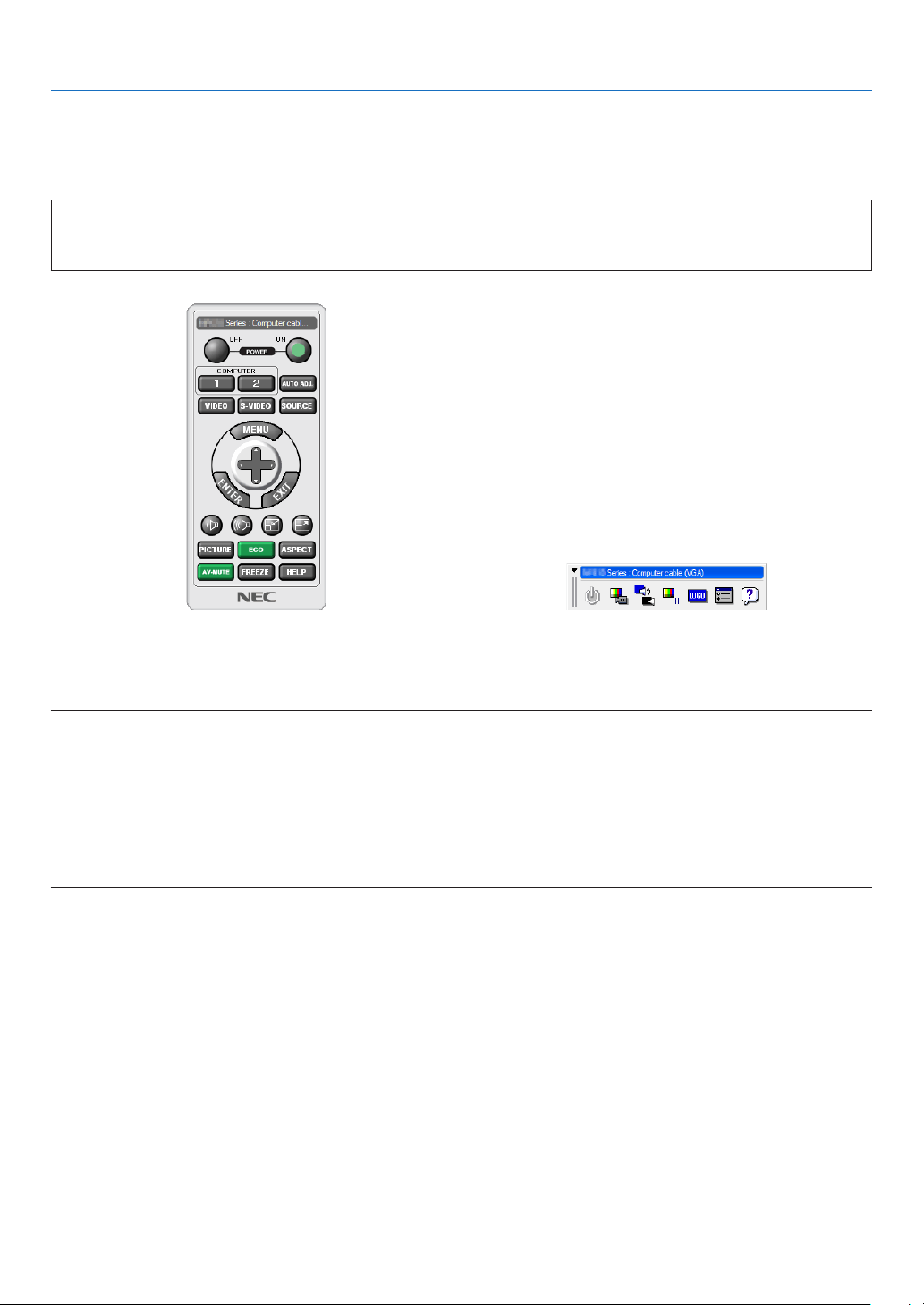
164
8. User Supportware
❸ Operating the Projector Via the LAN (Virtual Remote Tool)
Thiswillhelpyouperformoperationssuchasprojector’spoweronoroffandsignalselectionviaaLANconnection.It
isalsousedtosendanimagetotheprojectorandregisteritasthelogodataoftheprojector.Afterregisteringit,you
canlockthelogotopreventitfromchanging.
Control Functions
PowerOn/Off,signalselection,picturefreeze,picturemute,audiomute,Logotransfertotheprojector,andremote
controloperationonyourPC.
VirtualRemotescreen
RemoteControlWindow Toolbar
ThissectionprovidesanoutlineofpreparationforuseofVirtualRemoteTool.
ForinformationonhowtouseVirtualRemoteTool,seeHelpofVirtualRemoteTool.(→page166)
NOTE:
• Logodata(graphics)thatcanbesenttotheprojectorwithVirtualRemoteToolhasthefollowingrestrictions:
(OnlyviaserialorLANconnection)
* Filesize:Within256kilobytes
* Imagesize:Withintheresolutionoftheprojector
* Fileformat:PNG(Fullcolor)
• Logodata(image)sentusingtheVirtualRemoteToolwillbedisplayedinthecenterwiththesurroundingareainblack.
• Toputthedefault“NEClogo”backinthebackgroundlogo,youneedtoregisteritasthebackgroundlogobyusingtheimagele
(\Logo\NEC_logo2015_1920x1200.png)includedonthesuppliedNECProjectorCD-ROM.
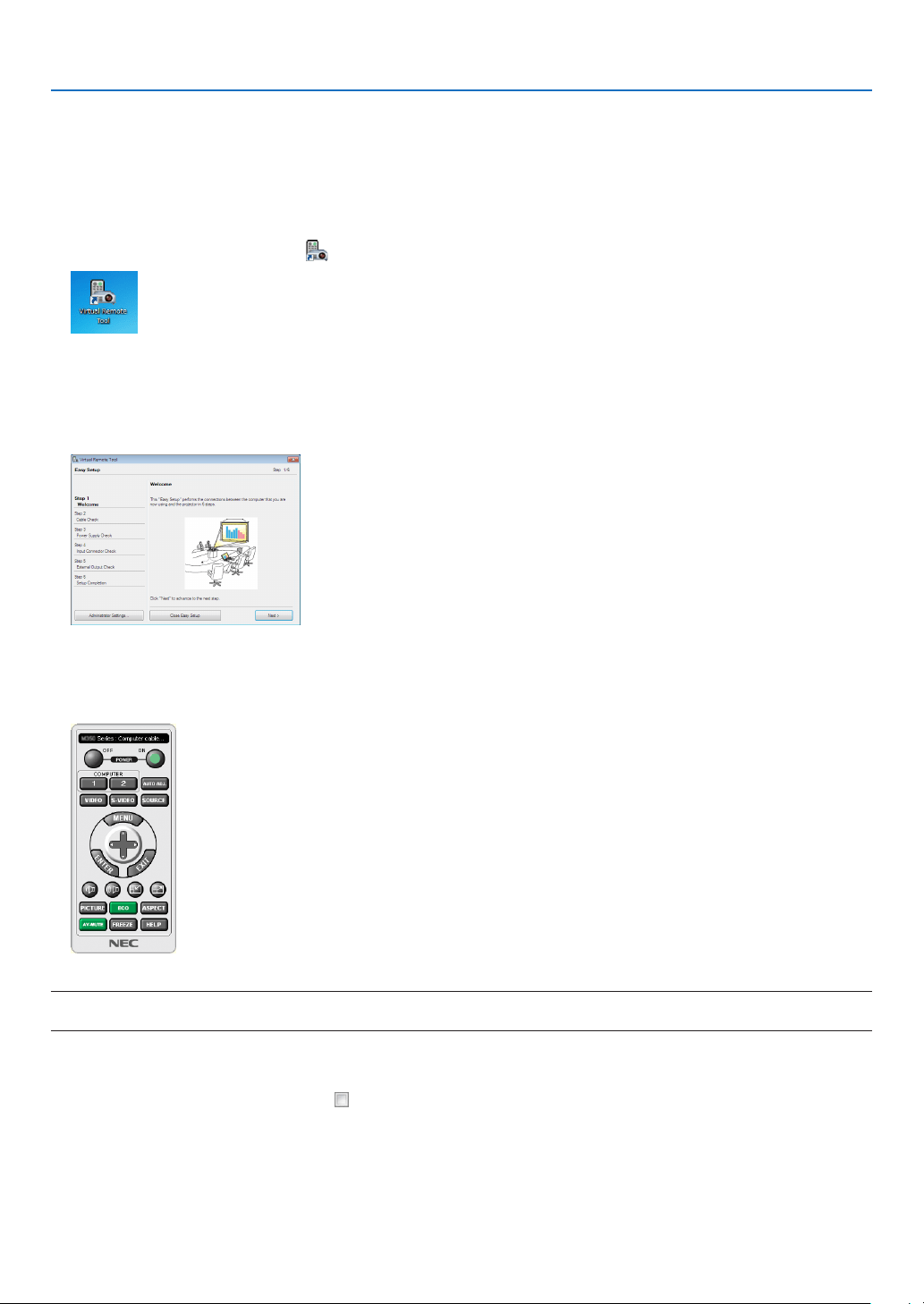
165
8. User Supportware
Connect the projector to a LAN.
ConnecttheprojectortotheLANbyfollowingtheinstructionsin“ConnectingtoaWiredLAN”(→page152)and“10.
ControllingtheProjectorbyUsinganHTTPBrowser”(→page52)
Start Virtual Remote Tool
Start using the shortcut icon
• Double-clicktheshortcuticon on the Windows Desktop.
Start from the Start menu
• Click[Start]→[AllPrograms]or[Programs]→[NECProjectorUserSupportware]→[VirtualRemoteTool]
→[VirtualRemoteTool].
WhenVirtualRemoteToolstartsforthersttime,“EasySetup”windowwillbedisplayed.
The“EasySetup”featureisnotavailableonthismodel.Click“CloseEasySetup”.
Closingthe“EasySetup”windowwilldisplaythe“ProjectorList”window.
Selectyourprojectoryouwishtoconnect.ThiswilldisplaytheVirtualRemotescreen.
NOTE:
• When[NORMAL]isselectedfor[STANDBYMODE]fromthemenu,theprojectorcannotbeturnedonvianetworkconnection.
TIP:
• TheVirtualRemoteToolscreen(orToolbar)canbedisplayedwithoutdisplaying“EasySetup”window.
Todoso,clicktoplaceacheckmarkfor“ DonotuseEasySetupnexttime”onthescreen.
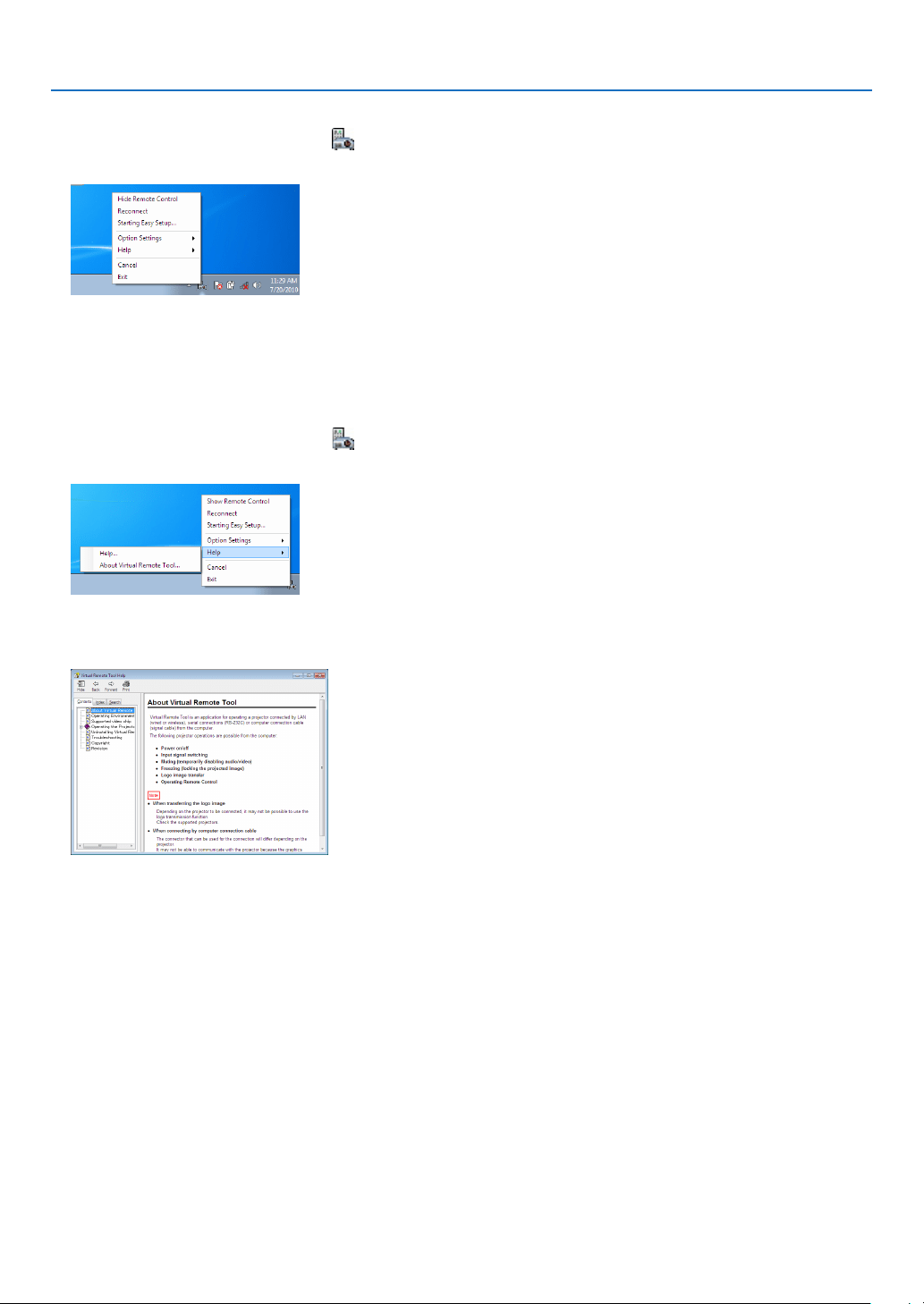
166
8. User Supportware
ExitingVirtualRemoteTool
1 ClicktheVirtualRemoteToolicon on the Taskbar.
Thepop-upmenuwillbedisplayed.
2 Click“Exit”.
TheVirtualRemoteToolwillbeclosed.
ViewingthehelpleofVirtualRemoteTool
•Displayingthehelpleusingthetaskbar
1 ClicktheVirtualRemoteToolicon onthetaskbarwhenVirtualRemoteToolisrunning.
Thepop-upmenuwillbedisplayed.
2. Click“Help”.
TheHelpscreenwillbedisplayed.
•DisplayingthehelpleusingtheStartMenu.
1. Click“Start”.“Allprograms”or“Programs”.“NECProjectorUserSupportware”.“VirtualRemoteTool”.and
then“VirtualRemoteToolHelp”inthisorder.
TheHelpscreenwillbedisplayed.

167
8. User Supportware
❹
Controlling the Projector over a LAN (PC Control Utility Pro 4/
Pro 5)
Usingtheutilitysoftware“PCControlUtilityPro4”or“PCControlUtilityPro5”includedonthecompanionNECPro-
jectorCD-ROM,theprojectorcanbecontrolledfromacomputeroveraLAN.
PCControlUtilityPro4isaprogramcompatiblewithWindows.(→thispage)
PCControlUtilityPro5isaprogramcompatiblewithMacOS.(→page170)
Control Functions
PowerOn/Off, signalselection,picturefreeze,picturemute,audiomute,adjusting,error messagenotication,
eventschedule.
ScreenofPCControlUtilityPro4
ThissectionprovidesanoutlineofpreparationforuseofPCControlUtilityPro4/Pro5.Forinformationonhowtouse
PCControlUtilityPro4/Pro5,seeHelpofPCControlUtilityPro4/Pro5.(→page169,170)
Step1:InstallPCControlUtilityPro4/Pro5onthecomputer.
Step2:ConnecttheprojectortoaLAN.
Step3:StartPCControlUtilityPro4/Pro5.
TIP:
• PCControlUtilityPro4canbeusedwithaserialconnection.
Using on Windows
Step 1: Install PC Control Utility Pro 4 on the computer
NOTE:
• Toinstalloruninstalltheprogram,theWindowsuseraccountmusthave[Administrator]privilege(Windows8.1,Windows8,
Windows7,WindowsVistaandWindowsXP)
• Exitallrunningprogramsbeforeinstallation.Ifanotherprogramisrunning,theinstallationmaynotbecompleted.
1 InserttheaccompanyingNECProjectorCD-ROMintoyourCD-ROMdrive.
Themenuwindowwillbedisplayed.
168
8. User Supportware
TIP:
Ifthemenuwindowwillnotbedisplayed,trythefollowingprocedure.
ForWindows7:
1. Click“start”onWindows.
2. Click“AllPrograms”→“Accessories”→“Run”.
3. Type your CD-ROM drive name (example:“Q:\”) and“LAUNCHER.EXE” in“Name”.(example: Q:\
LAUNCHER.EXE)
4. Click“OK”.
themenuwindowwillbedisplayed.
2 Click“PCControlUtilityPro4”onthemenuwindow.
Theinstallationwillstart.
Whentheinstallationiscomplete,theWelcomewindowwillbedisplayed.
3 Click“Next”.
“ENDUSERLICENSEAGREEMENT”screenwillbedisplayed.
Read“ENDUSERLICENSEAGREEMENT”carefully.
4 Ifyouagree,click“Iacceptthetermsinthelicenseagreement”andthenclick“Next”.
• Followtheinstructionsontheinstallerscreenstocompletetheinstallation.
• Whentheinstallationiscomplete,youwillreturntothemenuwindow.
TIP:
•UninstallingPCControlUtilityPro4
TouninstallPCControlUtilityPro4,dothesameproceduresstatedasin“UninstallingaSoftwareProgram”.(→ page 162, 163)

169
8. User Supportware
Step 2: Connect the projector to a LAN.
ConnecttheprojectortotheLANbyfollowingtheinstructionsin“ConnectingtoaWiredLAN”(→page152)and“10.
ControllingtheProjectorbyUsinganHTTPBrowser”(→page52)
Step 3: Start PC Control Utility Pro 4
Click“Start”→“Allprograms”or“Programs”→“NECProjectorUserSupportware”→“PCControlUtilityPro4”→
“PCControlUtilityPro4”.
NOTE:
• FortheSchedulefunctionofthePCControlutilityPro4towork,youmusthaveyourcomputerrunningandnotinstandby/
sleepmode.Select“PowerOptions”fromthe“ControlPanel”inWindowsanddisableitsstandby/sleepmodebeforerunningthe
scheduler.
[Example]ForWindows7:
Select“ControlPanel”→“SystemandSecurity”→“PowerOptions”→“Changewhenthecomputersleeps”→“Putthecomputer
tosleep”→“Never”.
NOTE:
• When[NORMAL]isselectedfor[STANDBYMODE]fromthemenu,theprojectorcannotbeturnedonviathenetwork(wiredLAN)
connection.
TIP:
ViewingtheHelpofPCControlUtilityPro4
• DisplayingtheHelpleofPCControlUtilityPro4whileitisrunning.
Click“Help(H)”→“Help(H)…”ofwindowofPCControlUtilityPro4inthisorder.
Thepop-upmenuwillbedisplayed.
• DisplayingthehelpleusingtheStartMenu.
Click“Start”→“Allprograms”or“Programs”→“NECProjectorUserSupportware”→“PCControlUtilityPro4”→
“PCControlUtilityPro4Help”.
TheHelpscreenwillbedisplayed.

170
8. User Supportware
Using on Mac OS
Step 1: Install PC Control Utility Pro 5 on the computer
1. InserttheaccompanyingNECProjectorCD-ROMinyourMacCD-ROMdrive.
TheCD-ROMiconwillbedisplayedonthedesktop.
2. Double-clicktheCD-ROMicon.
TheCD-ROMwindowwillbedisplayed.
3. Double-clickthe“MacOSX”folder.
4. Double-click“PCControlUtilityPro5.pkg”.
Theinstallerwillstart.
5. Click“Next”.
“ENDUSERLICENSEAGREEMENT”screenwillbedisplayed.
6. Read“ENDUSERLICENSEAGREEMENT”andclick“Next”.
Theconrmationwindowwillbedisplayed
7. Click“Iacceptthetermsinthelicenseagreement”.
Followtheinstructionsontheinstallerscreenstocompletetheinstallation.
Step 2: Connect the projector to a LAN
ConnecttheprojectortotheLANbyfollowingtheinstructionsin“ConnectingtoaWiredLAN”(→page152)and“10.
ControllingtheProjectorbyUsinganHTTPBrowser”(→page52)
Step 3: Start PC Control Utility Pro 5
1. OpenyourApplicationsfolderinMacOS.
2. Clickthe“PCControlUtilityPro5”folder.
3. Clickthe“PCControlUtilityPro5”icon.
PCControlUtilityPro5willstart.
NOTE:
• FortheSchedulefunctionofthePCControlutilityPro5towork,youmusthaveyourcomputerrunningandnotinsleepmode.
Select“EnergySaver”fromthe“SystemPreferences”inMacanddisableitssleepmodebeforerunningthescheduler.
• When[NORMAL]isselectedfor[STANDBYMODE]fromthemenu,theprojectorcannotbeturnedonviathenetwork(wiredLAN)
connection.
TIP:
ViewingtheHelpofPCControlUtilityPro5
•DisplayingtheHelpleofPCControlUtilityPro5whileitisrunning.
• Fromthemenubar,click“Help”→“Help”inthisorder.
TheHelpscreenwillbedisplayed.
•DisplayingtheHelpusingtheDock
1. Open“ApplicationFolder”inMacOS.
2. Clickthe“PCControlUtilityPro5”folder.
3. Clickthe“PCControlUtilityPro5Help”icon.
TheHelpscreenwillbedisplayed.

171
9. Appendix
❶ Throw distance and screen size
Thisprojectorcanbeusedwith8kindsofoptionallenses(soldseparately).Refertotheinformationonthispageand
usealenssuitedfortheinstallationenvironment(screensizeandthrowdistance).Forinstructionsonmountingthe
lens,seepage141.
Lens types and throw distance
Applicablelensunit:NP16FL/NP17ZL/NP18ZL/NP19ZL/NP20ZL/NP21ZL/NP31ZL
Screensize Lensunitmodelname
inch NP16FL NP31ZL NP17ZL NP18ZL NP19ZL NP20ZL NP21ZL
40
0.6- 0.8
50 0.8 0.8 - 1.0 1.3 -
1.9 1.8 - 2.4 2.4- 4.0 3.8 - 5.8 5.6- 8.9
60 1.0 1.0 - 1.2 1.6- 2.3 2.2- 2.9 2.8- 4.8 4.6- 7.0 6.8- 10.7
80 1.3 1.3 - 1.6 2.2- 3.1 3.0 - 3.9 3.8 - 6.4 6.2- 9.3 9.1- 14.4
100 1.7 1.6- 2.0 2.7- 3.9 3.7- 4.9 4.8- 8.0 7.7- 11.7 11.5 - 18.1
120
2.0 2.0- 2.5 3.3 - 4.7 4.5- 5.9 5.8 - 9.6 9.3- 14.1 13.8 - 21.7
150 2.5 2.5- 3.1 4.1- 5.8 5.6- 7.4 7.2- 12.0 11.7- 17.6 17.4- 27.3
200 3.4 3.3 - 4.1 5.5 - 7.8 7.5- 9.9 9.7- 16.1 15.6- 23.5 23.3- 36.4
240 4.1 4.0- 5.0 6.6- 9.4 9.1- 11.9 11.6- 19.3 18.8 - 28.3 28.0- 43.8
300 5.1 5.0 - 6.2 8.2- 11.7 11.3 - 14.9 14.5- 24.1 23.5- 35.4 35.0 - 54.8
350 5.8 - 7.3
400 6.6- 8.3
450
7.5- 9.4
500 8.3 - 10.4
TIP
Calculationofthethrowdistancefromthescreensize
NP16FLlensthrowdistance(m)=H×0.8:0.8m(min.)to5.1m(max.)
NP17ZLlensthrowdistance(m)=H×1.3toH×1.8:1.3m(min.)to11.7m(max.)
NP18ZLlensthrowdistance(m)=H×1.7toH×2.3:1.8m(min.)to14.9m(max.)
NP19ZLlensthrowdistance(m)=H×2.2toH×3.7:2.4m(min.)to24.1m(max.)
NP20ZLlensthrowdistance(m)=H×3.6toH×5.4:3.8m(min.)to35.4m(max.)
NP21ZLlensthrowdistance(m)=H×5.3toH×8.3:5.6m(min.)to54.8m(max.)
NP31ZLlensthrowdistance(m)=H×0.8toH×0.9:0.6m(min.)to10.4m(max.)
“H”(Horizontal)referstothescreenwidth.
*Figuresdifferbyseveral%withthetableabovebecausethecalculationisapproximate.
Ex.:Throwdistancewhenprojectingona150"screenusingtheNP18ZLlens:
Accordingtothe“ScreenSize(forreference)”table(→ page 173),H(screenwidth)=127.2"/323.1cm.
Thethrowdistanceis323.1cm×1.7to323.1cm×2.3=549.3cmto743.13cm(becauseofthezoomlens).
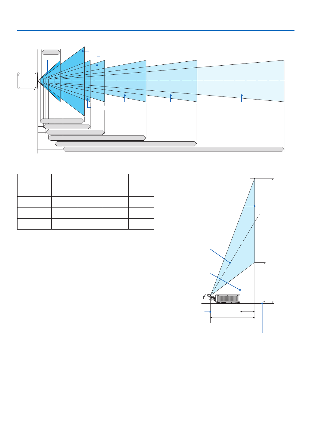
172
9. Appendix
Projection range for the different lenses
50-300"
40-500"
50-300"
50-300" 50-300" 50-300"
0.8–5.1 m
NP16FL :
NP17ZL: 1.3–11.7 m
NP31ZL: 0.6–10.4 m
NP18ZL: 1.8–14.9 m
NP19ZL: 2.4–24.1 m
NP20ZL: 3.8–35.4 m
NP21ZL: 5.6–54.8 m
50-300"
Applicablelensunit:NP39ML
Screensize
(inch)
Throw
distance
L1(m)
L2(m) H1(m) H2(m)
100 0.82 -0.024 2.05 0.71
120 0.97 0.13 2.43 0.81
150 1.20 0.35 3.00 0.98
200 1.57 0.73 3.95 1.26
250 1.95 1.11 4.90 1.54
300 2.33 1.49 5.85 1.81
350 2.71 1.87 6.81 2.09
TIP
Calculationofthethrowdistancefromthescreensize
NP39MLlensthrowdistance(m)=H×0.38:0.8m(min.)to
2.7m(max.)
“H”(Horizontal)referstothescreenwidth.
* Figuresdifferbyseveral%withthetableabovebecausethe
calculationisapproximate.
L1
H1
H2
L2
Screen face
Screen center
Projector rear face
Center of the lens unit
projection window
Projector bottom face
(In the condition the tilt foot is not
lengthen)
[Throw distance]
Screen
bottom
end
Screen top end

173
9. Appendix
Tables of screen sizes and dimensions
Screen
height
Screenwidth
16:10screensize
(diagonal)
Size(inches) Screenwidth Screenheight
(inches) (cm) (inches) (cm)
40 33.9 86.2 21.2 53.8
60 50.9 129.2 31.8 80.8
80 67.8 172.3 42.4 107.7
100 84.8 215.4 53.0 134.6
120 101.8 258.5 63.6 161.5
150 127.2 323.1 79.5 201.9
200 169.6 430.8 106.0 269.2
240 203.5 516.9 127.2 323.1
300 254.4 646.2 159.0 403.9
400 339.2 861.6 212.0 538.5
500 424.0 1077.0 265.0 673.1
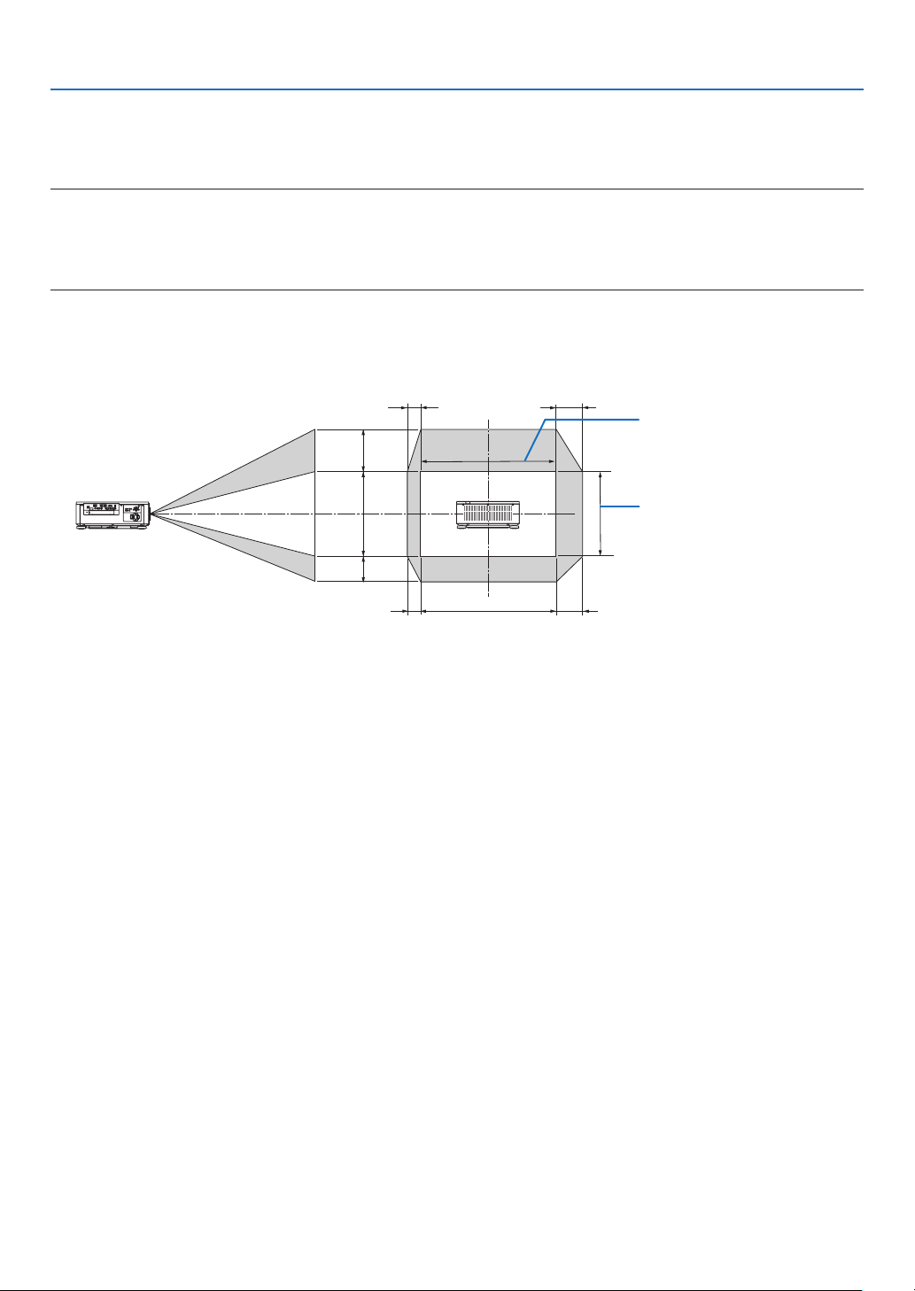
174
9. Appendix
Lens shifting range
ThisprojectorisequippedwithalensshiftfunctionforadjustingthepositionoftheprojectedimagebyusingtheLENS
SHIFTbuttons(→page23).Thelenscanbeshiftedwithintherangeshownbelow.
NOTE:
• Pleasedonotusethelensshiftfunctionwhenprojectingportraitimages.Pleaseuseitwiththelensinthecenterwhenoneamong
thelensunits,NP16FL,NP17ZL,NP18ZL,NP19ZL,NP20ZL,NP21ZLorNP31ZLisxedon.ForusingthelensunitNP39ML,
select[TYPE]for[LENSPOSITION]in[INSTALLATION(2)]in[SETUP]ontheonsceenmenuformovingthelensattheappropriate
position.
Legend:V“Vertical”referstothescreenheightandH“Horizontal”referstothescreenwidth.Thelensshiftrangeis
expressedasaratioofheightandwidth,respectively.
100%V
50%V
30%V
100%H
20%H
10%H
10%H
20%H
Heightofprojectedimage
Widthofprojectedimage
* Thelensshiftrangeisthesameforceilinginstallation.
(Example)Whenusingtoprojectona150"screen
Accordingtothe“Tableofscreensizesanddimensions”(→page173),H=127.2"/323.1cm,V=79.5"/201.9cm.
Adjustment range in the vertical direction: the projected image can be moved upwards 0.5 × 79.5"/201.9 cm≈
39.8"/101cm,downwardsapproximately39.8"/101cm(whenthelensisatthecenterposition).Adjustmentrangein
thehorizontaldirection:theprojectedimagecanbemovedtotheleft0.15×127.2"/323.1cm≈19.1"/48cm,tothe
rightapproximately19.1"/48cm.
* Figuresdifferbyseveral%becausethecalculationisapproximate.
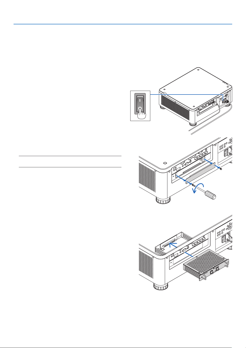
175
9. Appendix
❷ Mounting the Optional Board (sold separately)
CAUTION
Beforemountingorremovingtheoptionalboard,besuretoturnofftheprojector,waitforthefanstostopandturn
offthemainpowerswitch.
Toolneeded:Phillipsscrewdriver(plus-head)
1. Turnoffthemainpowerswitchoftheprojector.
2. LoosenthetwoscrewsontheSLOTcoverofthe
terminals.
RemovethetwoscrewsandtheSLOTcover.
NOTE:
• Keepthetwoscrewsandtheslotcover.
3. Insert the optional board into the slot.
Makesurethattheboardisinsertedintotheslotinthe
correctorientation.
Incorrect orientation may cause miscommunication
betweentheoptionalboardandprojector.
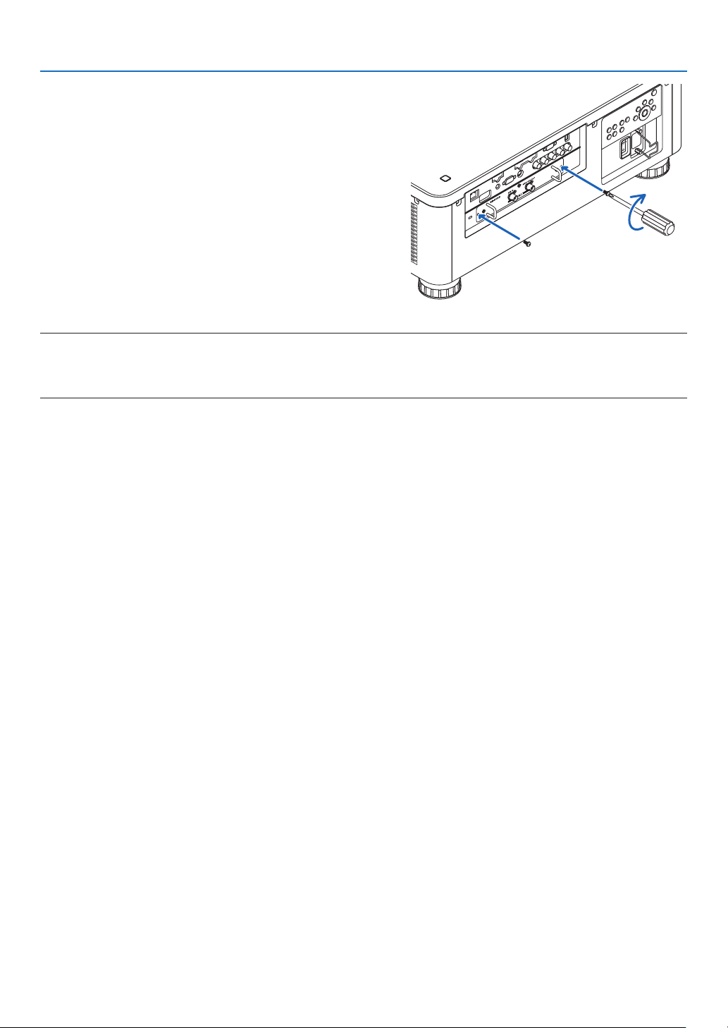
176
9. Appendix
4. Tightenthetwoscrewsonbothsidesoftheslot.
• Besuretotightenthescrews.
Thiswillcompleteinstallationoftheoptionalboard.
Toselecttheoptionalboardsource,selectSLOTasthe
input.
NOTE:
• Mountingtheoptionalboardmaycausethefanstoruninthestandbymodeforthepurposeofcoolingdependingontheoptional
board.Thefanspeedmayalsoincreaseinordertocooltheprojectorproperly.Bothoftheseinstancesareconsiderednormal
andnotamalfunctionoftheprojector.

177
9. Appendix
❸ Compatible Input Signal List
Analog Computer Signal
Signal Resolution(dots) AspectRatio RefreshRate(Hz)
VGA 640 × 480 4 : 3 60/72/75/85/iMac
SVGA 800 × 600 4 : 3 56/60/72/75/85/iMac
XGA 1024 × 768 4 : 3 60/70/75/85/iMac
XGA+ 1152 × 864 4 : 3 60/70/75/85
WXGA
1280 × 768 15 : 9 60
1280 × 800 16 : 10 60
1360 × 768 *
1
16 : 9 60
1366 × 768 *
1
16 : 9 60
Quad-VGA 1280 × 960 4 : 3 60/75/85
SXGA 1280 × 1024 5 : 4 60/75/85
SXGA+ 1400 × 1050 4 : 3 60/75
WXGA+ 1440 × 900 16 : 10 60
WXGA++ 1600 × 900 16 : 9 60
UXGA 1600 × 1200 *
2
4 : 3 60/65/70/75
WSXGA+ 1680 × 1050 16 : 10 60
WUXGA 1920 × 1200 *
2
16 : 10 60(ReducedBlanking)
2K 2048 × 1080 17 : 9 60
FullHD 1920 × 1080 *
2
16 : 9 60
MAC13" 640 × 480 4 : 3 67
MAC16" 832 × 624 4 : 3 75
MAC19" 1024 × 768 4 : 3 75
MAC21" 1152 × 870 *
3
4 : 3 75
MAC23" 1280 × 1024 5 : 4 65
Component
Signal Resolution(dots) AspectRatio RefreshRate(Hz)
HDTV(1080p) 1920 × 1080 16 : 9 50/60
HDTV(1080i) 1920 × 1080 16 : 9 50/60
HDTV(720p) 1280 × 720 16 : 9 50/60
SDTV(480p) 720 × 480 4:3/16:9 60
SDTV(576p) 720 × 576 4:3/16:9 50
SDTV(480i) 720 × 480 4:3/16:9 60
SDTV(576i) 720 × 576 4:3/16:9 50
CompositeVideo/S-Video
Signal AspectRatio RefreshRate(Hz)
NTSC 4 : 3 60
PA L 4 : 3 50
PAL60 4 : 3 60
SECAM 4 : 3 50

178
9. Appendix
HDMI
Signal Resolution(dots) AspectRatio RefreshRate(Hz)
VGA 640 × 480 4 : 3 60
SVGA 800 × 600 4 : 3 60
XGA 1024 × 768 4 : 3 60
HD 1280 × 720 16 : 9 60
WXGA
1280 × 768 15 : 9 60
1280 × 800 16 : 10 60
1366 × 768 *
1
16 : 9 60
Quad-VGA 1280 × 960 4 : 3 60
SXGA 1280 × 1024 5 : 4 60
SXGA+ 1400 × 1050 4 : 3 60
WXGA+ 1440 × 900 16 : 10 60
WXGA++ 1600 × 900 16 : 9 60
WSXGA+ 1680 × 1050 16 : 10 60
UXGA 1600 × 1200 *
2
4 : 3 60
FullHD 1920 × 1080 *
2
16 : 9 60
WUXGA 1920 × 1200 *
2
16 : 10 60(ReducedBlanking)
2K 2048 × 1080 17 : 9 60
WQHD
iMac27"
2560 × 1440 16 : 9 60
WQXGA 2560 × 1600 16 : 10
60(ReducedBlanking)
4K
3840 × 2160 16 : 9 23.98/24/25/29.97/30
4096 × 2160 17 : 9 24
HDTV(1080p) 1920 × 1080 16 : 9 50/60
HDTV(1080i) 1920 × 1080 16 : 9 50/60
HDTV(720p) 1280 × 720 16 : 9 50/60
SDTV(480i/p) 720/1440 × 480 4:3/16:9 60
SDTV(576i/p) 720/1440 × 576 4:3/16:9 50
HDMI3D
SignalResolution(dots) RefreshRate(Hz) AspectRatio 3DFormat
1920 × 1080p
23.98/24
16 : 9
FramePacking
TopandBottom
50 SideBySide
59.94/60 SideBySide
1920 × 1080i
50
SideBySide
59.94/60 SideBySide
1280 × 720p
50
FramePacking
SideBySide
TopandBottom
59.94/60
FramePacking
SideBySide
TopandBottom
179
9. Appendix
DisplayPort
Signal Resolution(dots) AspectRatio RefreshRate(Hz)
VGA 640 × 480 4 : 3 60
SVGA 800 × 600 4 : 3 60
XGA 1024 × 768 4 : 3 60
HD 1280 × 720 16 : 9 60
WXGA
1280 × 768 15 : 9 60
1280 × 800 16 : 10 60
1366 × 768 *
1
16 : 9 60
Quad-VGA 1280 × 960 4 : 3 60
SXGA 1280 × 1024 5 : 4 60
SXGA+ 1400 × 1050 4 : 3 60
WXGA+ 1440 × 900 16 : 10 60
WXGA++ 1600 × 900 16 : 9 60
WSXGA+ 1680 × 1050 16 : 10 60
UXGA 1600 × 1200 *
2
4 : 3 60
FullHD 1920 × 1080 *
2
16 : 9 60
WUXGA 1920 × 1200 *
2
16 : 10 60(ReducedBlanking)
2K 2048 × 1080 17 : 9 60
WQHD
iMac27"
2560 × 1440 16 : 9 60
WQXGA 2560 × 1600 16 : 10
60(ReducedBlanking)
4K
3840 × 2160 16 : 9 23.98/24/25/29.97/30
4096 × 2160 17 : 9 24
HDTV(1080p) 1920 × 1080 16 : 9 50/60
HDTV(1080i) 1920 × 1080 16 : 9 50/60
HDTV(720p) 1280 × 720 16 : 9 50/60
SDTV(480i/p) 720/1440 × 480 4:3/16:9 60
SDTV(576i/p) 720/1440 × 576 4:3/16:9 50
DisplayPort 3D
SignalResolution(dots) RefreshRate(Hz) AspectRatio 3DFormat
1920 × 1080p
23.98/24
16 : 9
SideBySide
TopandBottom
25
SideBySide
TopandBottom
50
SideBySide
TopandBottom
59.94/60
SideBySide
TopandBottom
1920 × 1080i
50
TopandBottom
SideBySide
59.94/60
TopandBottom
SideBySide
1280 × 720p
50
SideBySide
TopandBottom
59.94/60
FramePacking
SideBySide
TopandBottom
*1 Theprojectormayfailtodisplaythesesignalscorrectlywhen[AUTO]isselectedfor[ASPECTRATIO]intheon-screenmenu.
Thefactorydefaultis[AUTO]for[ASPECTRATIO].Todisplaythesesignals,select[16:9]for[ASPECTRATIO].
*2 Nativeresolution
*3 Theprojectormayfailtodisplaythesesignalscorrectlywhen[AUTO]isselectedfor[ASPECTRATIO]intheon-screenmenu.
Thefactorydefaultis[AUTO]for[ASPECTRATIO].Todisplaythesesignals,select[4:3]for[ASPECTRATIO].
• Signalsexceedingtheprojector’sresolutionarehandledwithAdvancedAccuBlend.
• WithAdvancedAccuBlend,thesizeofcharactersandruledlinesmaybeunevenandcolorsmaybeblurred.
• Uponshipment,theprojectorissetforsignalswithstandarddisplayresolutionsandfrequencies,butadjustmentsmayberequired
dependingonthetypeofcomputer.

180
9. Appendix
❹ Specifications
Modelname PX803UL-WH/PX803UL-BK
Method
SingleDLP
®
chip
Specicationsofmainparts
DMDpanel Size 0.67"(aspectratio:16:10)
Pixels
(*1)
2,304,000(1920dots×1200lines)
Projectionlenses Pleaserefertothespecicationsofoptionlens(→page182)
Lightsource LaserDiode
Opticaldevice Opticalisolationbydichroicmirror,combiningbydichroicprism
Lightoutput
(*2)
(*3)
8,000lm
Contrastratio
(*2)
(allwhite/allblack) 10,000:1withdynamiccontrast
Screensize(throwdistance) Pleaserefertothespecicationsofoptionlens(→page182)
Colorreproducibility 10-bitcolorprocessing(approx.1.07billioncolors)
Scanningfrequency Horizontal Analog:15kHz,24to100kHz(24kHzorgreaterforRGBinputs),conformingto
VESAstandards
Digital:15kHz,24to153kHz,conformingtoVESAstandards
Vertical Analog:48Hz,50to85Hz,100,120HzconformingtoVESAstandards
Digital:24,25,30,48Hz,50to85Hz,100,120HzconformingtoVESAstandards
Mainadjustmentfunctions Powerzoom,powerfocus,powerlensshift,inputsignalswitching(HDMI/DisplayPort/
BNC/BNC(CV)/BNC(Y/C)/COMPUTER/HDBaseT/SLOT),autoimageadjustment,pic-
turemaginication,muting(video),poweron/standby,on-screendisplay/selection,etc.
Max.displayresolution(horizontal×
vertical)
Analog:1920×1200(handledwithAdvancedAccuBlend)
Digital:4096×2160(handledwithAdvancedAccuBlend)
Inputsignals
R,G,B,H,V RGB:0.7Vp-p/75Ω
Y:1.0Vp-p/75Ω(withNegativePolaritySync)
Cb,Cr(Pb,Pr):0.7Vp-p/75Ω
H/VSync:4.0Vp-p/TTL
CompositeSync:4.0Vp-p/TTL
SynconG:1.0Vp-p/75Ω(withSync)
Compositevideo 1.0Vp-p/75Ω
S-Video
Y:1.0Vp-p/75Ω
C:286Vp-p/75Ω
Component
Y:1.0Vp-p/75Ω(withSync)
Cb,Cr(Pb,Pr):0.7Vp-p/75Ω
DTV:480i,480p,720p,1080i,1080p(60Hz)
576i,576p,720p,1080i,1080p(50Hz)
DVD:Progressivesignal(50/60Hz)
Input/outputterminals
Computer/Com-
ponent
Videoinput MiniD-Sub15-pin×1,BNCterminal×5
HDMI Videoinput HDMI
®
TerminaltypeA×1
DeepColor(colordepth):8-/10-/12-bitcompatible
Colorimetry:RGB,YcbCr444andYcbCr422compatible
LipSynccompatible,HDCPcompatible
(*4)
,Supports4Kand3D
Videooutput Repeater
Audioinput HDMI:Samplingfrequency–32/44.1/48kHz,Samplingbits–16/20/24bits
HDBaseT Videoinput DeepColor(colordepth):Support8/10/12bits
Colorimetry:SupportRGB,YCbCr444andYCbCr422
SupportLipSync,HDCP
(*4)
,4K,3D
Audioinput Samplingfrequency:32/44.1/48kHz
Samplingbit:16/20/24bit
DisplayPort Videoinput DisplayPort×1
Datarate:2.7Gbps/1.62Gbps
No.lanes:1lane/2lanes/4lanes
Colordepth:6-bit,8-bit,10-bit
Colorimetry:RGB,YcbCr444andYcbCr422compatible
HDCPcompatible
(*4)
Audioinput DisplayPort:Samplingfrequency–32/44.1/48kHz,Samplingbits–16/20/24bits
BNC(CV) Videoinput BNC×1
BNC(Y/C) Videoinput BNC×2
PCcontrolterminal D-Sub9-pin×1
USBport USBtypeA×1,USBtypeB×1(Forserviceonly)
Ethernet/HDBaseTport RJ-45×1,SupportsBASE-TX
Remoteterminal Stereominijack×1
3DSYNCoutputterminal 5V/10mA,synchronizedsignaloutputfor3Duse

181
9. Appendix
Modelname PX803UL-WH/PX803UL-BK
Usageenvironment
(*5)
Operatingtemperature:41to104°F(5to40°C)
Operatinghumidity:20to80%(withnocondensation)
Storagetemperature:14to140°F(-10to60°C)
Storagehumidity:20to80%(withnocondensation)
Operatingaltitude:0to3000m/10,000feet
Powersupply 100-240VAC,50/60Hz
Powercon-
sumption
LIGHT
MODE
NORMAL 874W(100-130V)/850W(200-240V)
ECO1 695W(100-130V)/680W(200-240V)
ECO2 456W(100-130V)/446W(200-240V)
STAND-
BY
MODE
NORMAL 0.18W(100-130V)/0.27W(200-240V)
NETWORK
STANDBY
4.3W(100-130V)/4.4W(200-240V)
Ratedinputcurrent 9.6A-4.0A
Externaldimensions 19.7"(width)×8.3"(height)×22.7"(depth)/500(width)×211(height)×577(depth)
mm(notincludingprotrudingparts)
19.7"(width)×8.5"(height)×23.0"(depth)/500(width)×216(height)×583(depth)
mm(includingprotrudingparts)
Weight 61.7lbs/28kg(notincludinglens)
*1 Effectivepixelsaremorethan99.99%.
*2 Thisisthelightoutputvaluethatresultsfromsettingthe[LIGHTMODE]to[NORMAL]andsettingthe[PRESET]to[HIGH-BRIGHT]
whileusingtheNP18ZLlens(soldseparately).
Thelightoutputvalueislowerwhensettingthe[LIGHTMODE]to[ECO1]or[ECO2].([ECO1]:about80%,[ECO2]:about50%).
Ifanyothermodeisselectedasthe[PRESET]mode,thelightoutputvaluemaydropslightly.
*3 CompliancewithISO21118-2012
*4 HDMI
®
(DeepColor,LipSync)withHDCP
WhatisHDCP/HDCPtechnology?
HDCPisanacronymforHigh-bandwidthDigitalContentProtection.HighbandwidthDigitalContentProtection(HDCP)isasystem
forpreventingillegalcopyingofvideodatasentoveraHigh-DenitionMultimediaInterface(HDMI).
IfyouareunabletoviewmaterialviatheHDMIinput,thisdoesnotnecessarilymeantheprojectorisnotfunctioningproperly.With
theimplementationofHDCP,theremaybecasesinwhichcertaincontentisprotectedwithHDCPandmightnotbedisplayed
duetothedecision/intentionoftheHDCPcommunity(DigitalContentProtection,LLC).
Video:DeepColor;8/10/12-bit,LipSync
Audio:LPCM;upto2ch,samplerate32/44.1/48KHz,samplebit;16/20/24-bit
*5 Dependingonthealtitudeandtemperature,theprojectorgoesinto“ForcedECOMODE”.
• Thesespecicationsandtheproduct’sdesignaresubjecttochangewithoutnotice.
Foradditionalinformationvisit:
US:http://www.necdisplay.com/
Europe:http://www.nec-display-solutions.com/
Global:http://www.nec-display.com/global/index.html
Forinformationonouroptionalaccessories,visitourwebsiteorseeourbrochure.

182
9. Appendix
Optionlens(soldseparately)
NP16FL Powerfocus
throwratio0.76:1,F1.85,f=11.6mm
ImageSize(Diagonal):50–300inches/1.27–7.62m
ProjectionDistance(Min.–Max.):0.81–5.08m
NP17ZL Powerzoomandfocus
throwratio1.25–1.79:1,F1.85–2.5,f=18.7–26.5mm
ImageSize(Diagonal):50–300inches/1.27–7.62m
ProjectionDistance(Min.–Max.):1.33–11.74m
NP18ZL Powerzoomandfocus
throwratio1.73–2.27:1,F1.64–1.86,f=25.7–33.7mm
ImageSize(Diagonal):50–300inches/1.27–7.62m
ProjectionDistance(Min.–Max.):1.83–14.88m
NP19ZL Powerzoomandfocus
throwratio2.22–3.67:1,F1.86–2.48,f=32.91–54.23mm
ImageSize(Diagonal):50–300inches/1.27–7.62m
ProjectionDistance(Min.–Max.):2.36–24.13m
NP20ZL Powerzoomandfocus
throwratio3.6–5.4:1,F1.85–2.41,f=52.8–79.1mm
ImageSize(Diagonal):50–300inches/1.27–7.62m
ProjectionDistance(Min.–Max.):3.80–35.36m
NP21ZL Powerzoomandfocus
throwratio5.3–8.3:1,F1.85–2.48,f=78.5–121.9mm
ImageSize(Diagonal):50–300inches/1.27–7.62m
ProjectionDistance(Min.–Max.):5.60–54.81m
NP31ZL Powerzoomandfocus
throwratio0.75–0.93:1,F1.96–2.3,f=11.3–14.1mm
ImageSize(Diagonal):40–500inches/1.02–12.7m
ProjectionDistance(Min.–Max.):0.62–10.41m
NP39ML Powerfocus
Throwratio0.38:1,F2.0,f=5.64mm
Imagesize(Diagonal):100–350inches/2.54–8.89m
ProjectionDistance(Min.–Max.):0.82–2.7m
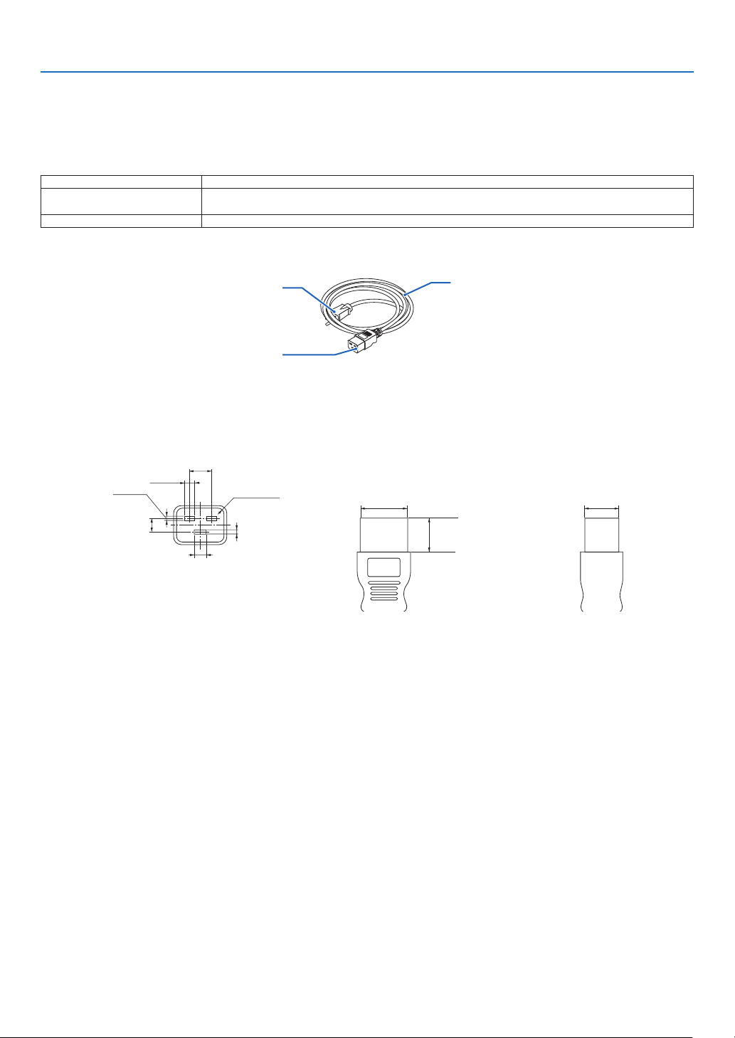
183
9. Appendix
Power Cord
Ifthesuppliedpowercordcannotbeusedorinyourareathevoltageconditionisdifferentfromthesuppliedpower
cord,usepowercordsthataresuitablefortheelectricalspecications,typesofpowercordsandregulationsofthe
countryofinstallation,asshowninthefollowingtableasshownbelow.Formoreinformation,contactyourdealer.
Power Cord Electrical Specifications
Powersupply Powercordelectricalspecs
AC100-130V 125V15Aorhigher
250V16Aorhigher
AC200-240V 250V16Aorhigher
Type of power cord
plug
connector
cord
Plug and cord
Yourplugmustcomplywithyourcountry’ssafetyrequirementsandyouroutlettype.
Connector
Dimensionsoftheconnectorofthepowercordareshownbelow
7
+0.5
−0
13±0.2
20min
2.5
+0.5
−0
8±0.2
2.5
+0.5
−0
R3.5min
6.0
+0.5
−0
28
+0
−0.9
20
+0
−0.7
Unit:mm
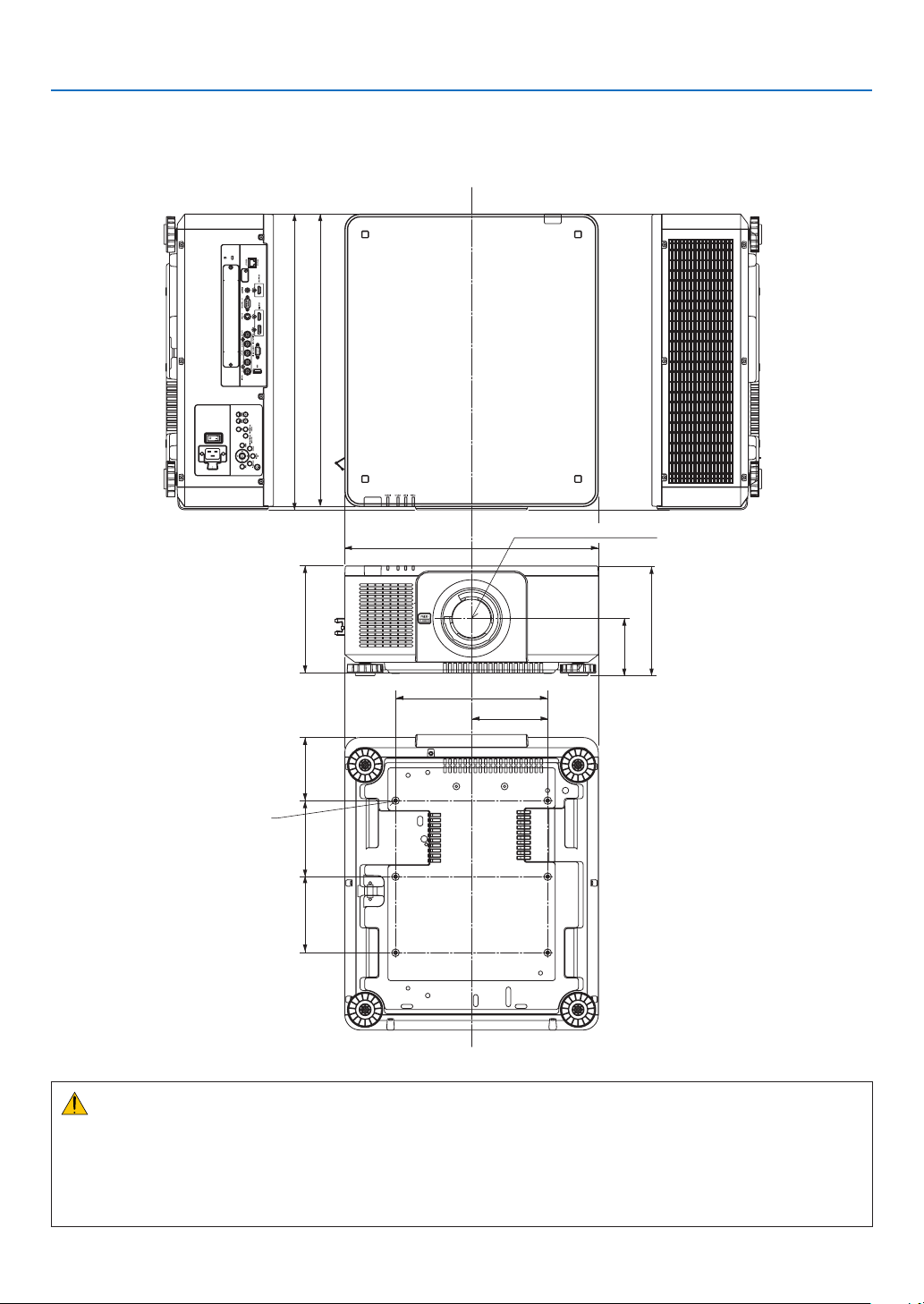
184
9. Appendix
❺ Cabinet Dimensions
Unit:mm(inch)
500 (19.7)
300 (11.8)
150 (5.9)
583 (23)
577 (22.7)
112.5 (4.4)
216 (8.5)
211 (8.3)
124.5 (4.9)150 (5.9)150 (5.9)
Lenscenter
6-M4×L16(Max)forCeiling
Mount*
* The screws specifications for
CeilingMount:
Screwtype:M4
Screw hole dimension on the
projector:M4withthemaximum
depth16mm(0.63")
CAUTION:
Donotattempttomounttheprojectoronaceilingyourself.
Theprojectormustbeinstalledbyqualiedtechniciansinordertoensureproperoperationandreducetheriskof
bodilyinjury.
Inaddition,theceilingmustbestrongenoughtosupporttheprojectorandtheinstallationmustbeinaccordance
withanylocalbuildingcodes.Pleaseconsultyourdealerformoreinformation.
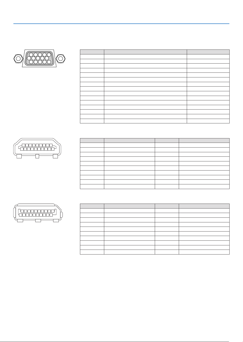
185
9. Appendix
❻ Pin assignments and signal names of main terminals
COMPUTER IN/ Component Input Terminal (Mini D-Sub 15 Pin)
Connection and signal level of each pin
51423
10
11 12 13 14 15
6978
Signal Level
Videosignal:0.7Vp-p(Analog)
Syncsignal:TTLlevel
Pin No. RGBSignal(Analog) YCbCrSignal
1 Red Cr
2
GreenorSynconGreen Y
3 Blue Cb
4 Ground
5 Ground
6
RedGround CrGround
7 GreenGround YGround
8 BlueGround CbGround
9 NoConnection
10 SyncSignalGround
11 NoConnection
12 Bi-directionalDATA(SDA)
13 HorizontalSyncorCompositeSync
14 VerticalSync
15 DataClock
HDMI IN Terminal (Type A)
135791113151719
246810 12 14 16 18
Pin No. Signal Pin No. Signal
1
TMDSData2+ 11 TMDSClockShield
2 TMDSData2Shield 12 TMDSClock−
3 TMDSData2− 13 CEC
4
TMDSData1+ 14 Disconnection
5
TMDSData1Shield 15 SCL
6
TMDSData1− 16 SDA
7
TMDSData0+ 17 DDC/CECgrounding
8 TMDSData0Shield 18 +5Vpowersupply
9 TMDSData0− 19 Hotplugdetection
10 TMDSClock+
DisplayPort IN Terminal
135791113151719
246810 12 14 16 18 20
Pin No. Signal Pin No. Signal
1
Mainlinklane3− 11 Grounding0
2 Grounding3 12 Mainlinklane0+
3 Mainlinklane3+ 13 Conguration1
4 Mainlinklane2− 14 Conguration2
5 Grounding2 15 Supplementarychannel+
6 Mainlinklane2+ 16 Grounding4
7 Mainlinklane1− 17 Supplementarychannel−
8 Grounding1 18 Hotplugdetection
9 Mainlinklane1+ 19 Return
10
Mainlinklane0− 20 +3.3Vpowersupply
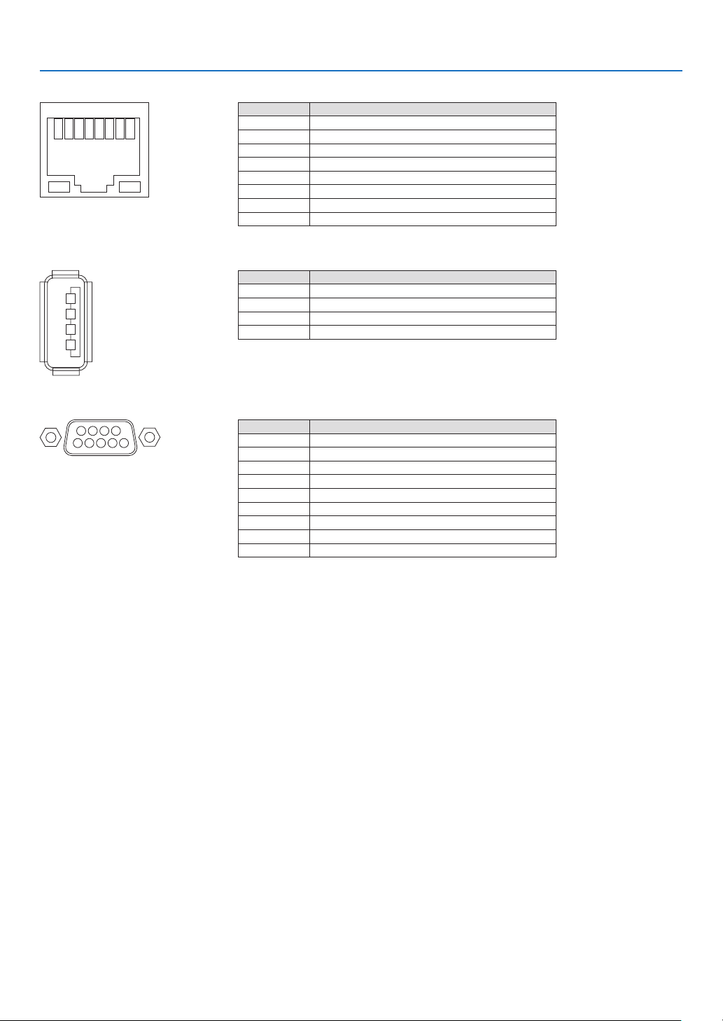
186
9. Appendix
Ethernet/HDBaseT Port (RJ-45)
12345678
Pin No. Signal
1 TxD+/HDBT0+
2 TxD−/HDBT0−
3 RxD+/HDBT1+
4 Disconnection/HDBT2+
5 Disconnection/HDBT2−
6 RxD−/HDBT1−
7 Disconnection/HDBT3+
8 Disconnection/HDBT3−
USB Port (Type A)
1
3
2
4
Pin No. Signal
1 V
BUS
2 D−
3 D+
4 Grounding
PC CONTROL Port (D-Sub 9 Pin)
1234
5
6789
Communications protocol
Pin No. Signal
1 Unused
2
RxD receptiondata
3 TxD transmissiondata
4 Unused
5 Grounding
6 Unused
7
RTS transmissionrequest
8 CTS transmissionallowed
9 Unused

187
9. Appendix
❼ Troubleshooting
Thissectionhelpsyouresolveproblemsyoumayencounterwhilesettinguporusingtheprojector.
Indicator Messages
POWER Indicator
Indicatordisplay Projectorstatus Procedure
Off Powerisoff. –
Flashing
Blue(shortashes) Preparingtoturnpoweron Waitawhile.
Blue(longashes) Offtimer(enabled)
Programtimer(offtimeenabled)
–
Orange(shortashes) Projectorcooling Waitawhile.
Orange(longashes) Programtimer(ontimeenabled) –
Lit Blue
Poweron –
Red Standbymode(NORMAL) –
Orange
Standbymode(NETWORKSTANDBY) –
STATUS Indicator
Indicatordisplay Projectorstatus Procedure
Off
Noproblem,orSTAND-
BYMODE-“NETWORK
STANDBY”
–
Flashing
Red(onceper
cycle)
Lensisnotxedon. Checkxingconditionsofthelens.
Red(four
timesper
cycle)
Fanproblem The cooling fan has stopped turning. Contact an NEC
projectorcustomersupportcenterforrepairs.
Orange Networkconict It is not possible to connect the projector’s built-in LAN
and wireless LAN simultaneously tothe same network.
Toconnecttheprojector’sbuilt-inLANandwirelessLAN
simultaneously,connectthemtodifferentnetworks.
Lit Green STANDBYMODEin
sleepmode*
–
Orange
Buttonhasbeen
pressedwhileprojector
isinkeylockmode
Theprojector’skeysarelocked.Thesettingmustbecan-
celedtooperatetheprojector.(→Page124)
Projector’sIDnumber
andremotecontrol’sID
numberdonotmatch
CheckthecontrolIDs.(→Pages125)
* Sleepmodereferstothestatewherebythefunctionalrestrictionsduetothestandbymodesettingareremoved.

188
9. Appendix
LIGHT Indicator
Indicatordisplay Projectorstatus Procedure
Off
Thelightmoduleis
turnedoff.
–
Flashing
Red(sixtimes
percycle)
Thelightsourceisnot
turnedon.
Waitforover1minuteandtrytopowerONtheprojector
again.Iftheproblemstillpersists,contacttheNECprojector
customersupportcenter.
Lit Green Lightmodulelit –
TEMP.Indicator
Indicatordisplay Projectorstatus Procedure
Off
Noproblem
Flashing Red(cycles
of2)
Temperatureproblem Thetemperatureprotectorhasbeenactivated.Iftheroom
temperatureishigh,movetheprojectortoacoolplace.If
theproblemstillpersists,contacttheNECprojectorcus-
tomersupportcenter.
Lit Orange Highsurroundingtem-
perature(ForcedECO
Mode)
The surrounding temperature is high. Lower the room
temperature.
If the temperature protector is activated
Iftheprojector’sinternaltemperaturerisesabnormally,thelightmoduleturnsoffandthetemperatureindicatorashes
(repeatedlytwoashespercycle).
Itmayhappenthattheprojector’stemperatureprotectorissimultaneouslyactivatedandtheprojector’spowerturnsoff.
Ifthishappens,dothefollowing:
- Unplugthepowercordfromthepoweroutlet.
- Ifusinginaplacewherethesurroundingtemperatureishigh,movetheprojectortoadifferent,coolplace.
- Ifthereisdustintheventilationslits,clean.(→page159)
- Waitassuchabout1hourfortheprojector’sinternaltemperaturetolower.

189
9. Appendix
Common Problems & Solutions
(→“POWER/STATUS/LIGHT/TEMP.Indicator”onpage186,187.)
Problem CheckTheseItems
Does not turn on
or shut down
• Checkthatthepowercordispluggedinandthatthepowerbuttonontheprojectorcabinetortheremote
control is on� (→ pages 14, 15)
• Checktoseeiftheprojectorhasoverheated.Ifthereisinsufcientventilationaroundtheprojectororifthe
room where you are presenting is particularly warm, move the projector to a cooler location�
• Thelightmodulemayfailtolight.Waitafullminuteandthenturnonthepoweragain.
• Incaseit’shardtothinkthetroubleisnotcausedontheabovementionedconditions,unplugthepower
cord from the outlet� Then wait 5 minutes before plugging it in again� (→ page 34)
Will turn off
• Ensurethatthe[OFFTIMER],[AUTOPOWEROFF]or[PROGRAMTIMER]isoff.(→ page 120, 135)
No picture
• Checkiftheappropriateinputisselected.(→ page 20) If there is still no picture, press the SOURCE button
or one of the source buttons again�
• Ensureyourcablesareconnectedproperly.
• Usemenustoadjustthebrightnessandcontrast.(→ page 93)
• CheckthattheSHUTTER(lensshutter)orAVMUTE(imageoff)buttonsarenotpressed.
• Checkthe[POWERONSHUTTER]intheonscreenmenuisnotsetto[CLOSE].
• Resetthesettingsoradjustmentstofactorypresetlevelsusingthe[RESET]intheMenu.(→ page 136)
• EnteryourregisteredkeywordiftheSecurityfunctionisenabled.(→ page 45)
• IftheHDMIINortheDisplayPortINsignalcannotbedisplayed,trythefollowing.
- Reinstall your driver for the graphics card built in your computer, or use the updated driver�
For reinstalling or updating your driver, refer to the user guide accompanied with your computer or
graphics card, or contact the support center for your computer manufacturer�
Install the updated driver or OS on your own responsibility�
We are not liable for any trouble and failure caused by this installation�
• SignalsmaynotbesupporteddependingontheHDBaseTtransmissiondevice.IRandRS232Ccannotbe
used in certain cases as well�
• BesuretoconnecttheprojectorandnotebookPCwhiletheprojectorisinstandbymodeandbeforeturning
on the power to the notebook PC�
In most cases the output signal from the notebook PC is not turned on unless connected to the projector
before being powered up�
* If the screen goes blank while using your remote control, it may be the result of the computer’s screen-
saver or power management software�
• Seealsothepage190�
Picture suddenly
becomes dark
• CheckiftheprojectorisintheForcedECOmodebecauseoftoohighambienttemperature.
Color tone or hue is
unusual
• Checkifanappropriatecolorisselectedin[WALLCOLOR].Ifso,selectanappropriateoption.(→ page
115)
• Adjust[HUE]in[PICTURE].(→ page 93)
Image isn’t square to
the screen
• Repositiontheprojectortoimproveitsangletothescreen.(→ page 22)
• UsetheKeystonecorrectionfunctiontocorrectthetrapezoiddistortion.(→ page 42)
Picture is blurred
• Adjustthefocus.(→ page 26)
• Repositiontheprojectortoimproveitsangletothescreen.(→ page 22)
• Ensurethatthedistance between theprojectorandscreen is withintheadjustmentrange ofthelens.
(→ page 171)
• Hasthelensbeenshiftedbyanamountexceedingtheguaranteedrange?(→ page 174)
• Condensationmayformonthelensiftheprojectoriscold,broughtintoawarmplaceandisthenturned
on� Should this happen, let the projector stand until there is no condensation on the lens�
Image is scrolling
vertically, horizontally
or both
• Checkthecomputer’sresolutionandfrequency.Makesurethattheresolutionyouaretryingtodisplayis
supported by the projector� (→ page 177)
• AdjustthecomputerimagemanuallywiththeHorizontal/Verticalinthe[IMAGEOPTIONS].(→ page 94)
Remote control does
not work
• Installnewbatteries.(→ page 11)
• Makesuretherearenoobstaclesbetweenyouandtheprojector.
• Standwithin22feet(7m)oftheprojector.(→ page 12)
Indicator is lit or
blinking
• SeethePOWER/STATUS/LIGHT/TEMP.Indicator.(→ page 186, 187)


191
9. Appendix
If there is no picture, or the picture is not displayed correctly.
• PoweronprocessfortheprojectorandthePC.
BesuretoconnecttheprojectorandnotebookPCwhiletheprojectorisinstandbymodeandbeforeturningon
thepowertothenotebookPC.
InmostcasestheoutputsignalfromthenotebookPCisnotturnedonunlessconnectedtotheprojectorbefore
beingpoweredup.
NOTE:Youcancheckthehorizontalfrequencyofthecurrentsignalintheprojector’smenuunderInformation.Ifitreads“0kHz”,
thismeansthereisnosignalbeingoutputfromthecomputer.(→ page 137orgotonextstep)
• Enablingthecomputer’sexternaldisplay.
DisplayinganimageonthenotebookPC’sscreendoesnotnecessarilymeanitoutputsasignaltotheprojector.
WhenusingaPCcompatiblelaptop,acombinationoffunctionkeyswillenable/disabletheexternaldisplay.Usu-
ally,thecombinationofthe“Fn”keyalongwithoneofthe12functionkeysgetstheexternaldisplaytocomeon
oroff.Forexample,NEClaptopsuseFn+F3,whileDelllaptopsuseFn+F8keycombinationstotogglethrough
externaldisplayselections.
• Non-standardsignaloutputfromthecomputer
IftheoutputsignalfromanotebookPCisnotanindustrystandard,theprojectedimagemaynotbedisplayed
correctly.Shouldthishappen,deactivatethenotebookPC’sLCDscreenwhentheprojectordisplayisinuse.Each
notebookPChasadifferentwayofdeactivate/reactivatethelocalLCDscreensasdescribedinthepreviousstep.
Refertoyourcomputer’sdocumentationfordetailedinformation.
• ImagedisplayedisincorrectwhenusingaMac
WhenusingaMacwiththeprojector,settheDIPswitchoftheMacadapter(notsuppliedwiththeprojector)ac-
cordingtoyourresolution.Aftersetting,restartyourMacforthechangestotakeaffect.
ForsettingdisplaymodesotherthanthosesupportedbyyourMacandtheprojector,changingtheDIPswitchon
aMacadaptermaybounceanimageslightlyormaydisplaynothing.Shouldthishappen,settheDIPswitchto
the13"xedmodeandthenrestartyourMac.Afterthat,restoretheDIPswitchestoadisplayablemodeandthen
restarttheMacagain.
NOTE:AVideoAdaptercablemanufacturedbyAppleComputerisneededforaMacBookwhichdoesnothaveaminiD-Sub
15-pinterminal.
• MirroringonaMacBook
* WhenusingtheprojectorwithaMacBook,outputmaynotbesetto1024×768unless“mirroring”isoffonyour
MacBook.Refertoowner’smanualsuppliedwithyourMaccomputerformirroring.
• FoldersoriconsarehiddenontheMacscreen
Foldersoriconsmaynotbeseenonthescreen.Shouldthishappen,select[View]→[Arrange]fromtheApple
menuandarrangeicons.
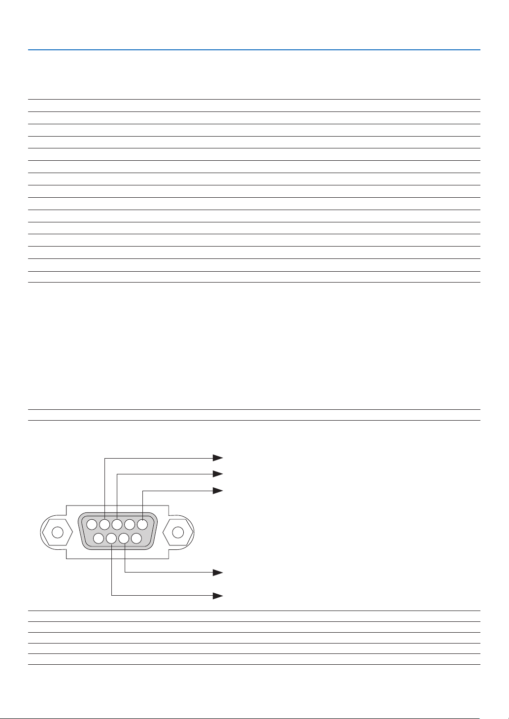
192
9. Appendix
❽ PC Control Codes and Cable Connection
PC Control Codes
Function Code Data
POWER ON 02H 00H 00H 00H 00H 02H
POWER OFF 02H 01H 00H 00H 00H 03H
INPUT SELECT HDMI 02H 03H 00H 00H 02H 01H A1H A9H
INPUT SELECT DisplayPort 02H 03H 00H 00H 02H 01H A6H AEH
INPUT SELECT BNC 02H 03H 00H 00H 02H 01H 02H 0AH
INPUT SELECT BNC(CV) 02H 03H 00H 00H 02H 01H 06H 0EH
INPUT SELECT BNC(Y/C) 02H 03H 00H 00H 02H 01H 0BH 13H
INPUT SELECT COMPUTER 02H 03H 00H 00H 02H 01H 01H 09H
INPUT SELECT HDBaseT 02H 03H 00H 00H 02H 01H 20H 28H
INPUT SELECT SLOT 02H 03H 00H 00H 02H 01H ABH B3H
PICTURE MUTE ON 02H 10H 00H 00H 00H 12H
PICTURE MUTE OFF 02H 11H 00H 00H 00H 13H
NOTE:ContactyourlocaldealerforafulllistofthePCControlCodesifneeded.
Cable Connection
CommunicationProtocol
Baud rate �����������������������������������������38400 bps
Data length
��������������������������������������8 bits
Parity
�����������������������������������������������No parity
Stop bit
��������������������������������������������One bit
X on/off
��������������������������������������������None
Communications procedure
�������������Full duplex
NOTE:Dependingontheequipment,alowerbaudratemayberecommendedforlongcableruns.
PC Control Terminal (D-SUB 9P)
NOTE1:Pins1,4,6and9arenoused.
NOTE2:Jumper“RequesttoSend”and“CleartoSend”togetheronbothendsofthecabletosimplifycableconnection.
NOTE3:Forlongcablerunsitisrecommendedtosetcommunicationspeedwithinprojectormenusto9600bps.
15243
67 98
ToGNDofPC
ToRxDofPC
ToTxDofPC
ToRTSofPC
ToCTSofPC

193
9. Appendix
❾ Troubleshooting Check List
Beforecontactingyourdealerorservicepersonnel,checkthefollowinglisttobesurerepairsareneededalsoby
referringtothe“Troubleshooting”sectioninyouruser’smanual.Thischecklistbelowwillhelpussolveyourproblem
moreefciently.
* Printthispageandthenextpageforyourcheck.
Frequency of occurrence □ always □sometimes(Howoften?_____________________) □other(__________________)
Power
□
No power (POWER indicator does not light blue)� See also “Status
Indicator (STATUS)”�
□
Power cord’s plug is fully inserted into the wall outlet�
□
No power even though you press and hold the POWER button�
□
The main power switch is in the “ON (I)” position�
□
Shut down during operation�
□
Power cord’s plug is fully inserted into the wall outlet�
□
[AUTO POWER OFF] is turned off (only models with the [AUTO
POWER OFF] function)�
□
[OFF TIMER] is turned off (only models with the [OFF TIMER]
function)�
Video and Audio
□
No image is displayed from your PC or video equipment to the
projector�
□
Still no image even though you connect the projector to the PC
first, then start the PC�
□
Enabling your notebook PC’s signal output to the projector�
• Acombinationoffunctionkeyswillenable/disabletheexter-
naldisplay.Usually,thecombinationofthe“Fn”keyalong
withoneofthe12functionkeysturnstheexternaldisplay
on or off.
□
No image (blue or black background, no display)�
□
Still no image even though you press the AUTO ADJUST button�
□
Still no image even though you carry out [RESET] in the
projector’s menu�
□
Signal cable’s plug is fully inserted into the input terminal
□
A message appears on the screen�
(_____________________________________________)
□
The source connected to the projector is active and available�
□
Still no image even though you adjust the brightness and/or
the contrast�
□
Input source’s resolution and frequency are supported by the
projector�
□
Image is too dark�
□
Remains unchanged even though you adjust the brightness
and/or the contrast�
□
Image is distorted�
□
Image appears to be trapezoidal (unchanged even though you
carry out the [KEYSTONE] adjustment)�
□
Parts of the image are lost�
□
Still unchanged even though you press the AUTO ADJUST
button�
□
Still unchanged even though you carry out [RESET] in the
projector’s menu�
□
Image is shifted in the vertical or horizontal direction�
□
Horizontal and vertical positions are correctly adjusted on a
computer signal�
□
Input source’s resolution and frequency are supported by the
projector�
□
Some pixels are lost�
□
Image is flickering�
□
Still unchanged even though you press the AUTO ADJUST
button�
□
Still unchanged even though you carry out [RESET] in the
projector’s menu�
□
Image shows flickering or color drift on a computer signal�
□
Still unchanged even though you change [FAN MODE] from
[HIGH] to [AUTO]�
□
Image appears blurry or out of focus�
□
Still unchanged even though you checked the signal’s resolution
on PC and changed it to projector’s native resolution�
□
Still unchanged even though you adjusted the focus�
Other
□
Remote control does not work�
□
No obstacles between the sensor of the projector and the
remote control�
□
Projector is placed near a fluorescent light that can disturb the
infrared remote controls�
□
Batteries are new and are not reversed in installation�
□
Buttons on the projector cabinet do not work (only models with the
[CONTROL PANEL LOCK] function)
□
[CONTROL PANEL LOCK] is not turned on or is disabled in
the menu�
□
Still unchanged even though you press and hold the SOURCE
button for a minimum of 10 seconds�
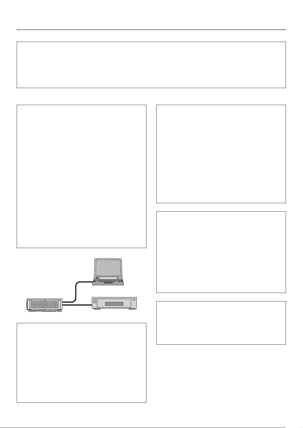
194
9. Appendix
In the space below please describe your problem in detail.
Information on application and environment where your projector is used
Projector
PC
Blu-rayplayer
Projector
Model number:
Serial No�:
Date of purchase:
Light module operating time (hours):
Eco Mode: □ OFF □ ON
Information on input signal:
Horizontal synch frequency [ ] kHz
Vertical synch frequency [ ] Hz
Synch polarity H □ (+) □ (−)
V □ (+) □ (−)
Synch type □ Separate □ Composite
□ Sync on Green
STATUS Indicator:
Steady light □ Orange □ Green
Flashing light [ ] cycles
Remote control model number:
Installation environment
Screen size: inch
Screen type: □ White matte □ Beads □ Polarization
□
Wide angle □ High contrast
Throw distance: feet/inch/m
Orientation: □ Ceiling mount □ Desktop
Power outlet connection:
□
Connected directly to wall outlet
□ Connected to power cord extender or other (the
numberofconnectedequipment______________)
□ Connected to a power cord reel or other (the number
ofconnectedequipment______________)
Computer
Manufacturer:
Model number:
Notebook PC □ / Desktop □
Native resolution:
Refresh rate:
Video adapter:
Other:
Videoequipment
VCR, Blu-ray player, Video camera, Video game or other
Manufacturer:
Model number:
Signal cable
NECstandardorothermanufacturer’scable?
Model number: Length: inch/m
Distribution amplifier
Model number:
Switcher
Model number:
Adapter
Model number:

©NECDisplaySolutions,Ltd.2015 7N952341