Home
Bookmarks
Home
NEC
NEC PX-42VP1A User Manual
Page 56
NEC PX-42VP1A 42" Plasma Display
User’s Manual - Page 56
For PX-42VP1A.
PDF File Manual
,
64 pages
,
Read Online
|
Download pdf file
Important Information
Precautions
Warnings And Safety Precaution
Limited Warranty
How To Attach Options To The Plasma Monitor
Introduction
Introduction To The PlasmaSync 42/50PD1
The Features You'll Enjoy Include
Contents Of The Package
OPTIONS
Setup Procedure
Part Names And Functions
Front View
Side View Terminal Board L/R
Remote Controller
Battery Installation And Replacement
Operating Range / Using The Wired Remote Control Mode
Making The DIP Switch Settings
DIP Switch Functions And Settings
Power Management Function
Power Management Modes
Installation
Wiring Diagram
Connecting Your PC Or Macintosh Computer
Connections With Equipment That Has A Digital Interface
Connecting Your VCR Or Laser Disc Player
Connecting Your Document Camera
Daisychaining Your Monitors
Operation
Power/General Controls/Adjustment Of The Display
Adjustment Of The Display (Direct)
Returning The Screen Adjustment To The Factory Default Settings (NORMAL)
Adjustment Of The Image
Returning The Image Adjustments To The Factory Default Settings (NORMAL)
Adjustment Of The Display (Menu Control)
List Of Setting Details
Before Making Adjustments
To Reset The Adjustment Value (to The Factory Default Setting) During The Setting
Adjustment Of The Image (Visual Controls)
Adjustment Of Screen Position (Horizontal)
Adjustment Of Screen Position (Vertical)
Color Temperature
Adjustment Of The White Balance
Adjustment Of The Onscreen Display Position
Setting The Onscreen Display OFF Time
Adjustment Of The Clock Frequency/Clock Phase (AUTO PICTURE)
Normal Screen
Next Page Screen
Information Screen
Timer Screen
Auto Timer Screen
Multiple Screens
Other Setting Screens (1)
Other Setting Screens (2)
Set Selection Screen For Allotting ID Numbers To Multiple Screens/Each Set
Troubleshooting
Specifications
Appendix
Signal Identification For Raster Preset
Pin Configuration And Signal Level Of Mini D–Sub 15Pin (Analog) Input Connector
Pin Configuration And Signal Of The RGB 3 IN Connector (DVI Connector)
Function And Pin Configuration Of The External Control Connector
Cabinet Dimensions
Page 56/64
Page 1
Page 2
Page 3
Page 4
Page 5
Page 6
Page 7
Page 8
Page 9
Page 10
Page 11
Page 12
Page 13
Page 14
Page 15
Page 16
Page 17
Page 18
Page 19
Page 20
Page 21
Page 22
Page 23
Page 24
Page 25
Page 26
Page 27
Page 28
Page 29
Page 30
Page 31
Page 32
Page 33
Page 34
Page 35
Page 36
Page 37
Page 38
Page 39
Page 40
Page 41
Page 42
Page 43
Page 44
Page 45
Page 46
Page 47
Page 48
Page 49
Page 50
Page 51
Page 52
Page 53
Page 54
Page 55
Page 56
Page 57
Page 58
Page 59
Page 60
Page 61
Page 62
Page 63
Page 64
Contents
Table of Contents
Search
Previous
Next
Troubleshooting
Bookmarks
Loading ...
Loading ...
Loading ...
56
Loading ...
Loading ...
Loading ...
File type: PDF
File name: 52737211_px-42vp1a.pdf
File size: 1.03 MB
File Language: English
Pages: 64
Author: NEC
File created: 2000-01-15
Published:
2023-11-12
Updated: 2023-11-17
Verified by
Delores Murray
on 2023-11-17
Download File
Table of Contents
×
Important Information
2
Precautions
2
Warnings And Safety Precaution
2
Limited Warranty
6
How To Attach Options To The Plasma Monitor
8
Introduction
9
Introduction To The PlasmaSync 42/50PD1
9
The Features You'll Enjoy Include
9
Contents Of The Package
9
OPTIONS
9
Setup Procedure
10
Part Names And Functions
12
Front View
12
Side View Terminal Board L/R
13
Remote Controller
14
Battery Installation And Replacement
15
Operating Range / Using The Wired Remote Control Mode
16
Making The DIP Switch Settings
17
DIP Switch Functions And Settings
17
Power Management Function
18
Power Management Modes
18
Installation
19
Wiring Diagram
19
Connecting Your PC Or Macintosh Computer
20
Connections With Equipment That Has A Digital Interface
20
Connecting Your VCR Or Laser Disc Player
20
Connecting Your Document Camera
20
Daisychaining Your Monitors
21
Operation
22
Power/General Controls/Adjustment Of The Display
22
Adjustment Of The Display (Direct)
23
Returning The Screen Adjustment To The Factory Default Settings (NORMAL)
23
Adjustment Of The Image
24
Returning The Image Adjustments To The Factory Default Settings (NORMAL)
24
Adjustment Of The Display (Menu Control)
25
List Of Setting Details
25
Before Making Adjustments
26
To Reset The Adjustment Value (to The Factory Default Setting) During The Setting
27
Adjustment Of The Image (Visual Controls)
29
Adjustment Of Screen Position (Horizontal)
30
Adjustment Of Screen Position (Vertical)
31
Color Temperature
32
Adjustment Of The White Balance
33
Adjustment Of The Onscreen Display Position
34
Setting The Onscreen Display OFF Time
35
Adjustment Of The Clock Frequency/Clock Phase (AUTO PICTURE)
36
Normal Screen
37
Next Page Screen
38
Information Screen
39
Timer Screen
40
Auto Timer Screen
41
Multiple Screens
43
Other Setting Screens (1)
44
Other Setting Screens (2)
45
Set Selection Screen For Allotting ID Numbers To Multiple Screens/Each Set
46
Troubleshooting
47
Specifications
48
Appendix
50
Signal Identification For Raster Preset
50
Pin Configuration And Signal Level Of Mini D–Sub 15Pin (Analog) Input Connector
51
Pin Configuration And Signal Of The RGB 3 IN Connector (DVI Connector)
51
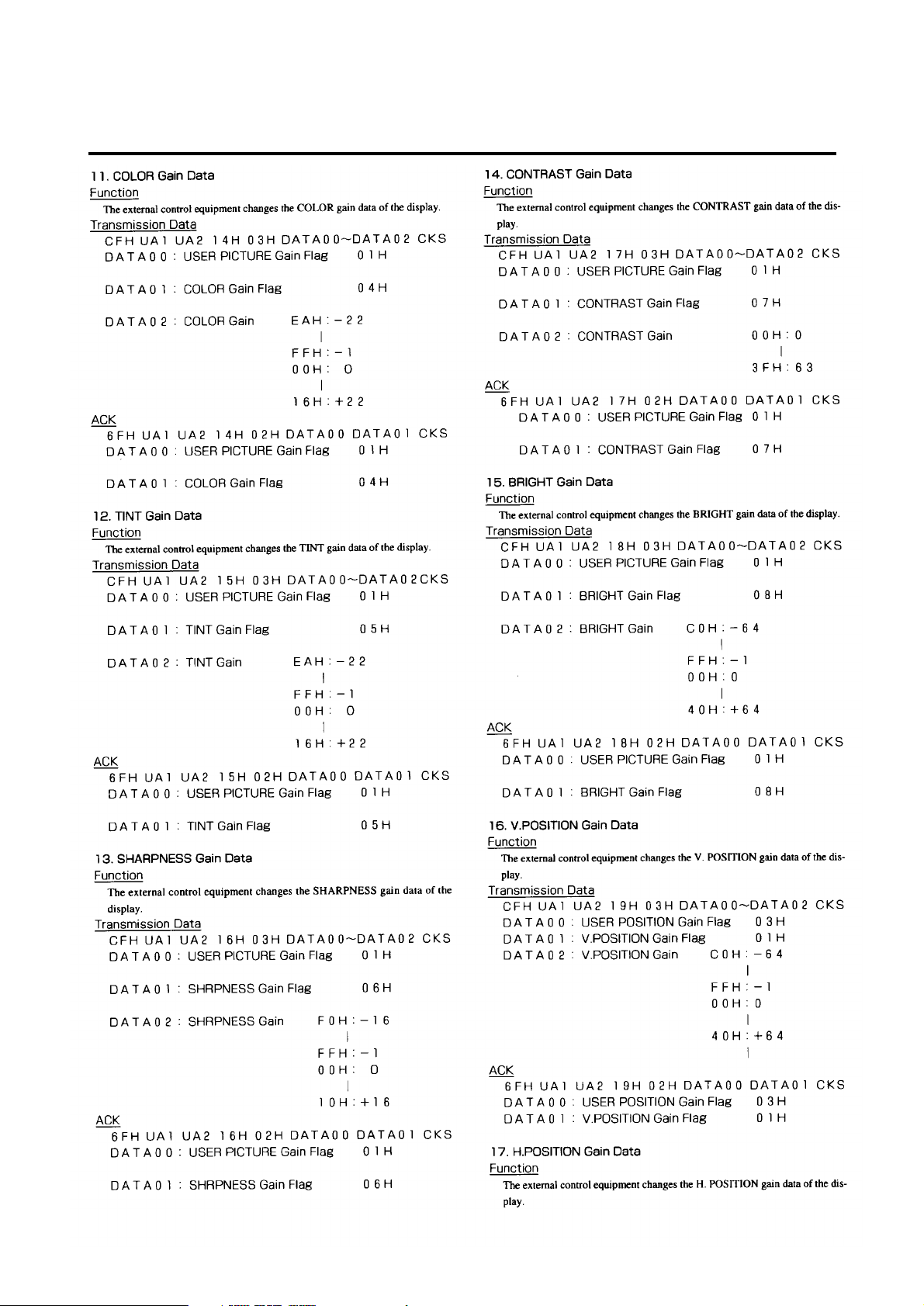
Function And Pin Configuration Of The External Control Connector
52
Cabinet Dimensions
63
Search:
×
Search