Loading ...
Loading ...
Loading ...
51
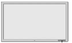
Pin No.
1
2
3
4
5
6
7
8
9
10
11
12
13
14
15
Signal (Analog)
Red
Green or sync-on-green
Blue
Ground
Ground
Red ground
Green ground
Blue ground
No connection
Sync signal ground
Ground
Bi-directional DATA (SDA)
Horizontal or composite sync
Vertical sync
Data clock
1
2
34
5
11
12
13
1415
6
7
8
9
10
Signal level
VIDEO signal : 0.7Vp-p (Analog)
Sync signal : TTL level
Pin Configuration and Signal Level of mini D-Sub 15-Pin (Analog) Input Connector
RGB 1
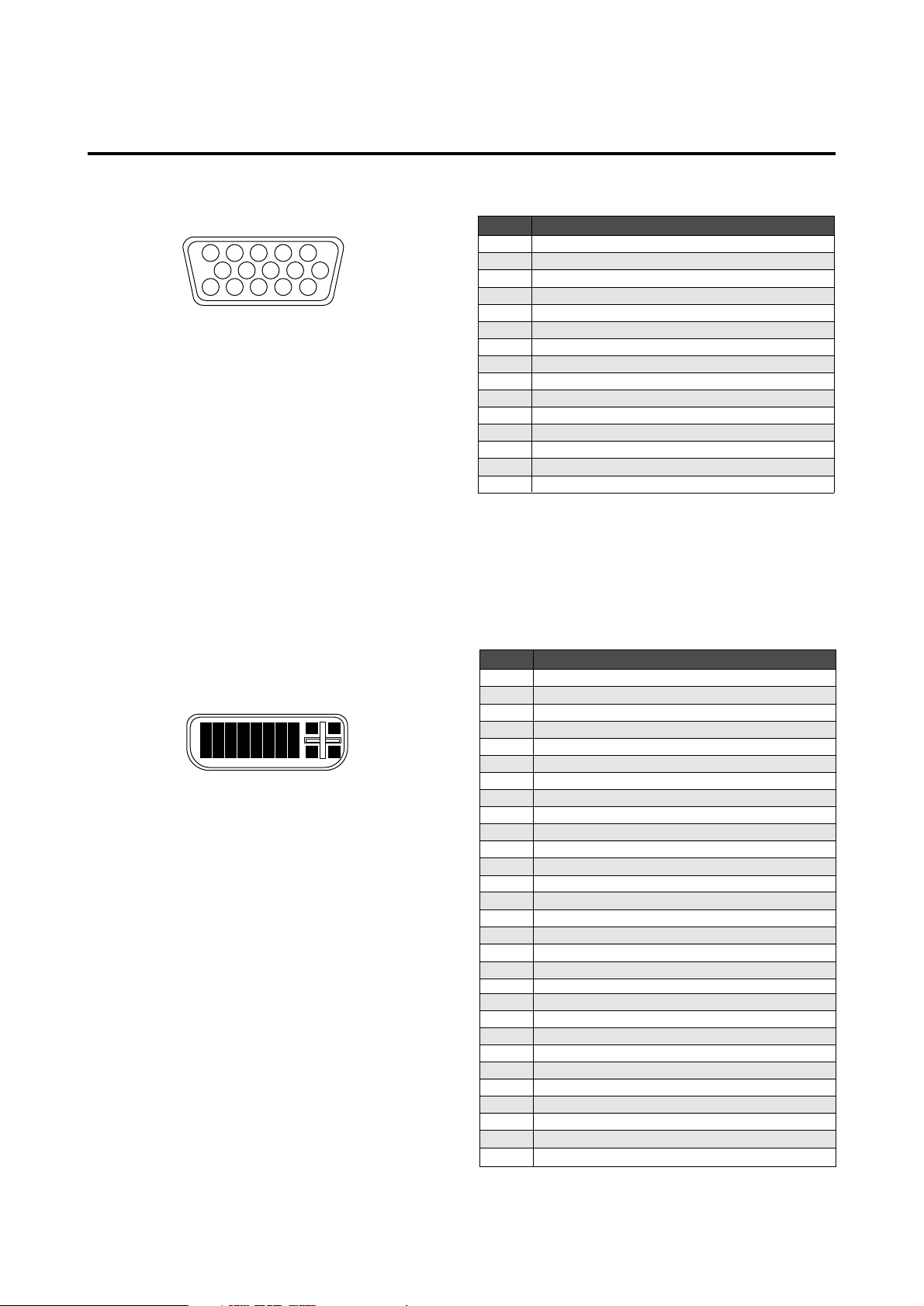
Pin Configuration and Signal of the RGB 3 IN Connector (DVI Connector)
Pin No.
1
2
3
4
5
6
7
8
9
10
11
12
13
14
15
16
17
18
19
20
21
22
23
24
25
26
27
28
29
Signal (Digital)
T.M.D.S Data 2 -
T.M.D.S Data 2 +
T.M.D.S Data 2 Shield
No connection
No connection
DDC Clock
DDC Data
No connection
T.M.D.S Data 1 -
T.M.D.S Data 1 +
T.M.D.S Data 1 Shield
No connection
No connection
+5V Power
Ground
Hot Plug Detect
T.M.D.S Data 0 -
T.M.D.S Data 0 +
T.M.D.S Data 0 Shield
No connection
No connection
T.M.D.S Clock Shield
T.M.D.S Clock +
T.M.D.S Clock -
No connection
No connection
No connection
No connection
No connection
1
9
17
2
10
18
3
11
19
4
12
20
5
13
21
6
14
22
7
15
23
8 25 26
27 28
16
24
29
RGB 3
The unit is equipped with a type of connector commonly
used for both analog and digital.
(Functionally, this cannot be used for analog input.)
(TMDS can be used for one link only)
Loading ...
Loading ...
Loading ...