Loading ...
Loading ...
Loading ...
SEIRWCE A ADJUSTME
llllll,llli i ,
TS
FRONT-TO-BACK ADJUSTMENT (See Figs. 20 and 21 )-
IMPORTANT: DECK MUST BE LEVEL SIDE-TO-SIDE. iF
THE FOLLOWING FRONT-TO-BACK ADJUSTMENT iS
NECESSARY, BE SURE TO ADJUST BOTH FRONT LINKS
EQUALLY SO MOWER WILL STAY LEVEL SIDE-TO-SIDE.
To obtain the best cutting results, the mower housing
should be adjusted so the front is approximately 1/8" to 1/2"
lower than the rear when the mower is in its highest
position,
Check adjustment on right side of tractor. Measure dis-
tance "F" directly in front of and behind the mandrel at
bottom edge of mower housing as shown.
- Before making any necessary adjustments, check that
both front links are equal in length.
o If links are not equal in length, adjust one link to same
length as other link.
= To lower-front of mower housing, loosen nut"G"on both
front links an equal number of turns.
. When distance "F" is 1/8" to 1/2" lower at front than
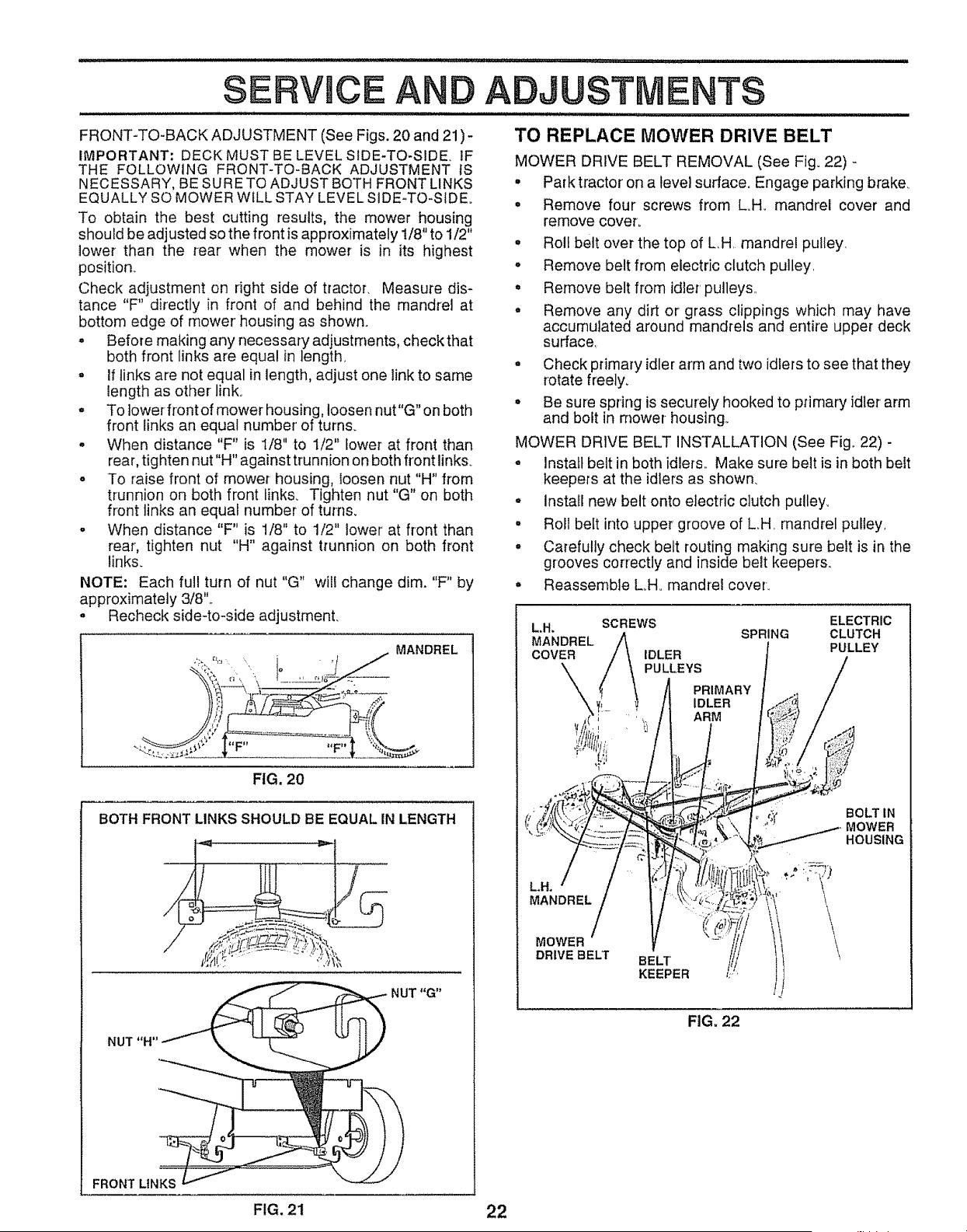
TO REPLACE MOWER DRIVE BELT
MOWER DRIVE BELT REMOVAL (See Fig. 22) -
° Park tractor' on a level surface. Engage parking brake.
= Remove four screws from LH. mandrel cover and
remove cover.
° Roll belt over the top of LH mandrel pulley.
° Remove belt from electric clutch pulley.
° Remove belt from idler pulleys.
° Remove any dirt or grass clippings which may have
accumulated around mandrels and entire upper deck
surface,
° Check primary idler arm and two idlers to see that they
rotate freely.
° Be sure spring is securely hooked to primary idler arm
and bolt in mower housing.,
MOWER DRIVE BELT INSTALLATION (See Fig, 22) -
rear, tighten nut "H" against trunnion on both front links.
° To raise front of mower housing, loosen nut "H" from
trunnion on both front links. Tighten nut "G" on both
front links an equal number of turns.
- When distance "F" is 1/8" to 1/2" lower' at front than
rear, tighten nut "H" against trunnion on both front
links.
NOTE: Each full turn of nut "G" will change dim. "F" by
approximately 3/8"..
= Recheck side-to-side adjustment.
... % . ,_ . MANDREL
,¢,
FIG. 20
BOTH FRONT LINKS SHOULD BE EQUAL IN LENGTH
NUT "H"
FRONT LINKS
o install belt in both idlers.. Make sure belt is in both belt
keepers at the idlers as shown.
, Install new belt onto electric clutch pulley.
° Roll belt into upper groove of LH. mandrel pulley.
, Carefully check belt routing making sure belt is in the
grooves correctly and inside belt keepers..
° Reassemble LH. mandrel cover.
ELECTRIC
LH. SCREWS SPRING CLUTCH
MANDREL PULLEY
COVER IDLER
PULLEYS
PRIMARY
IDLER
ARM
MANDREL
t;, BOLT IN
• MOWER
HOUSING
MOWER
DRIVE BELT
BELT
KEEPER
FIG, 22
FIG. 21 22
Loading ...
Loading ...
Loading ...