
1
Owner’s Manual
Metered Rack PDU
Model: PDUMH20HV
(Series Number: AGPD7985)
Important Safety Instructions 2
Installation 3
Features 6
Warranty and Product Registration 7
Español 8
Français 15
Русский 22
Deutsch 29
TrippLite.Eaton.com/support
Copyright © 2023 Tripp Lite. All rights reserved.
PROTECT YOUR INVESTMENT!
Register your product for quicker service
and ultimate peace of mind.
You could also win an
ISOBAR6ULTRA surge protector—
a $100 value!
www.tripplite.com/warranty

2
Important Safety Instructions
SAVE THESE INSTRUCTIONS
This manual contains instructions and warnings that should be
followed during the installation, operation, and storage of this product.
Failure to heed these instructions may affect your warranty.
• The PDU provides the convenience of multiple outlets, but DOES NOT provide surge or
line noise protection for connected equipment.
• The PDU is designed for indoor use only, in a controlled environment, away from excess
moisture, temperature extremes, conductive contaminants, dust or direct sunlight.
• Keep indoor ambient temperature between 32°F and 104°F (0°C and 40°C)
•ThePDUmustbeinstalledbyaqualiedtechnicianonly.
• Do not attempt to mount the PDU to an insecure or unstable surface.
• Install in accordance with National Electrical Code standards. Be sure to use the
proper overcurrent protection for the installation, in accordance with the plug/
equipment rating.
• Connect the PDU to an outlet that is in accordance with your local building codes and
that is adequately protected against excess currents, short circuits and earth faults.
• The electrical outlets supplying power to the equipment should be installed near the
equipment and easily accessible.
• Do not connect the PDU to an ungrounded outlet or to extension cords or adapters that
eliminate the connection to ground.
• Be sure to provide a local disconnect device on any models that are permanently
installed without a plug that is easily accessible.
• Never attempt to install electrical equipment during a thunderstorm.
• Individual equipment connected to the PDU should not draw more current than the
individual PDU’s outlet’s rating.
• The total load connected to the PDU must not exceed the maximum load rating for the
PDU.
• Do not attempt to modify the PDU, input plugs or power cables.
• Do not drill into or attempt to open any part of the PDU housing. There are no user-
serviceable parts inside.
• Do not attempt to use the PDU if any part of it becomes damaged.
• Use of this equipment in life support applications where failure of this equipment
can reasonably be expected to cause the failure of the life support equipment or to
signicantlyaffectitssafetyoreffectivenessisnotrecommended.Donotusethis
equipmentinthepresenceofaammableanestheticmixturewithair,oxygenor
nitrous oxide.
3
1
Determine Installation Conguration
This PDU supports 1U and 0U rackmount, wall-mount, and under-counter
installationcongurations.Chooseacongurationandfollowtheappropriate
installation instructions.
Note: Regardless of installation conguration, the user must determine the tness of
hardware and procedures before mounting. The PDU and included hardware are designed
for common rack and rack enclosure types and may not be appropriate for all applications.
Exact mounting congurations may vary.
Installation
1-3
1-1
1-2
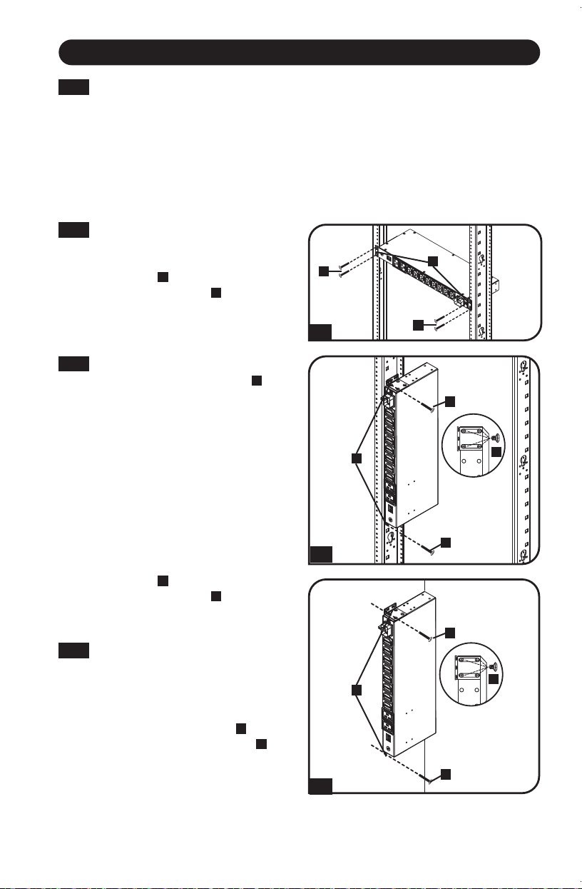
1-1
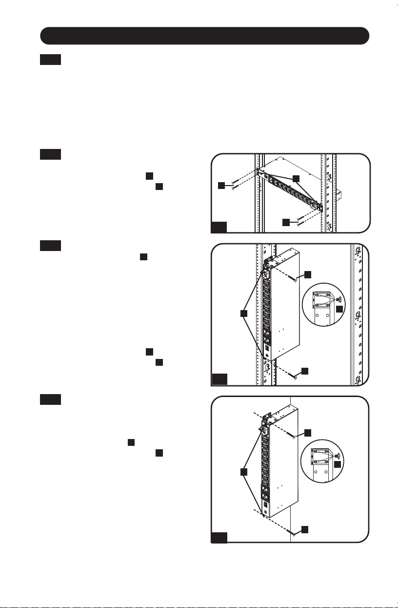
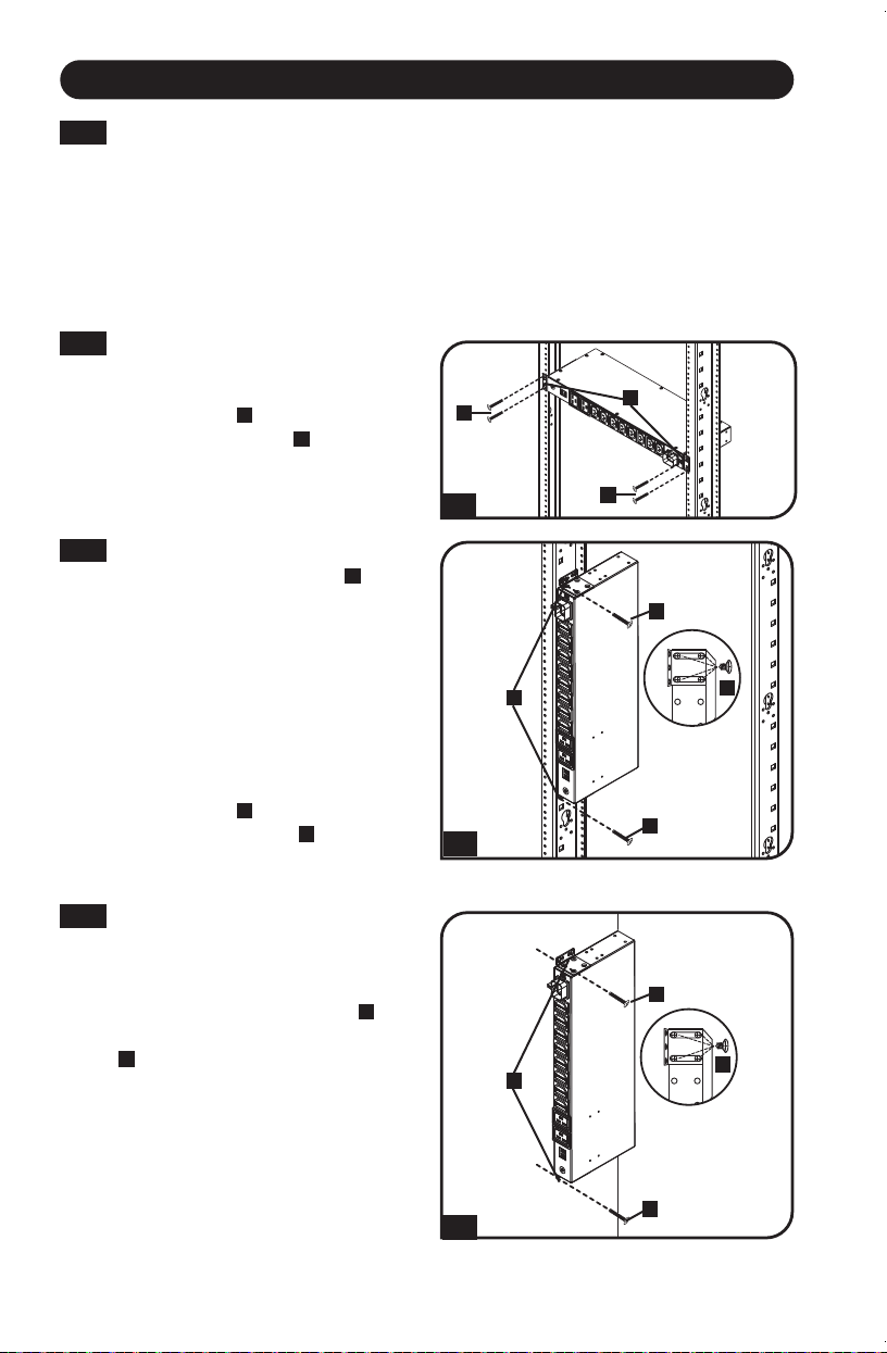
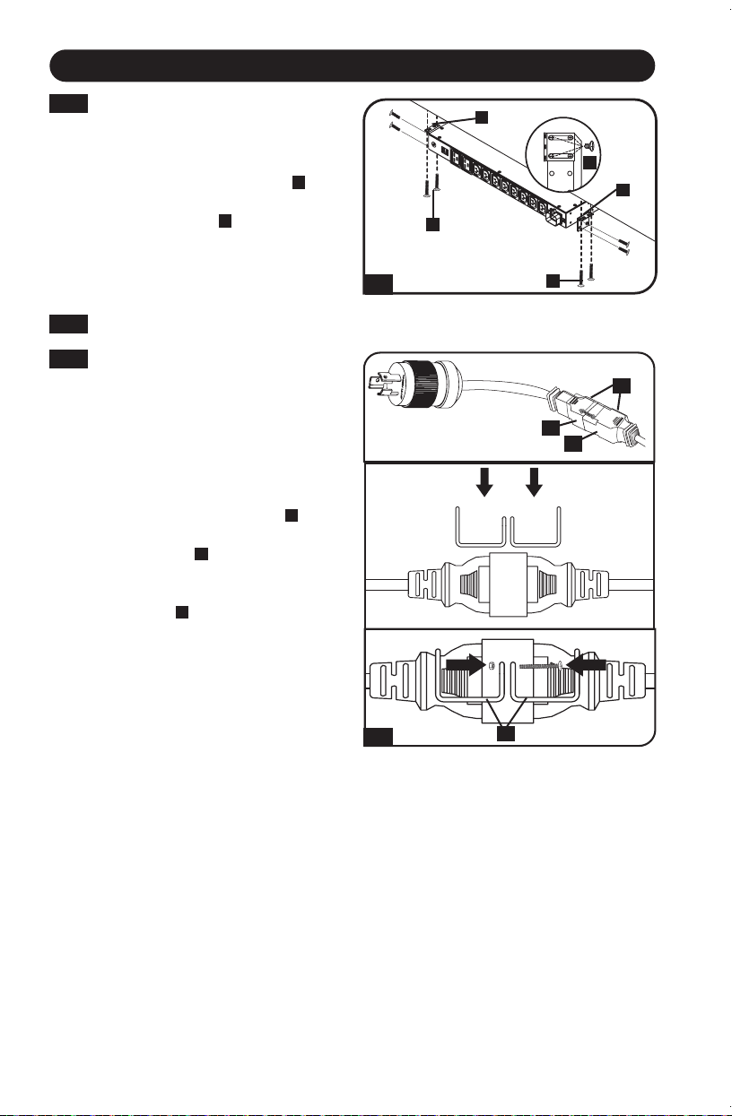
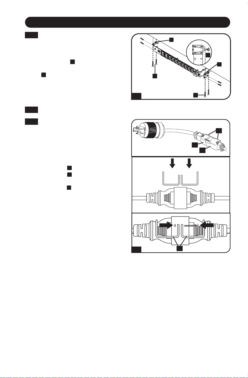
1U Rack Installation: Attach the
PDU to the rack by inserting four
user-supplied screws
A
through the
PDU mounting brackets
B
and into
the mounting holes of the rack rail
as shown.
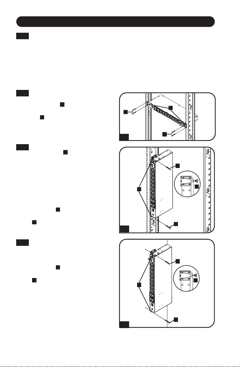
1-2
0U Rack Installation: Part 1:
Remove the screws
C
attaching
the mounting brackets to the PDU,
change the orientation of the
brackets as shown and reattach
the brackets. Use only the screws
supplied by the manufacturer or
their exact equivalent (#6-32, 1/4”
athead).Part 2: Attach the PDU
vertically by inserting two or more
user-supplied screws
A
through the
PDU mounting brackets
B
and into
mounting points in the rack or rack
enclosure.
1-3
Wall Installation: After repeating
Part 1 in Step 1-2, attach the
PDU to a stable mounting surface
by inserting two or more user-
supplied screws
A
through the
PDU mounting brackets
B
and into
secure mounting points on the
mounting surface.
A
A
A
A
A
A
B
B
B
C
C
4
Installation
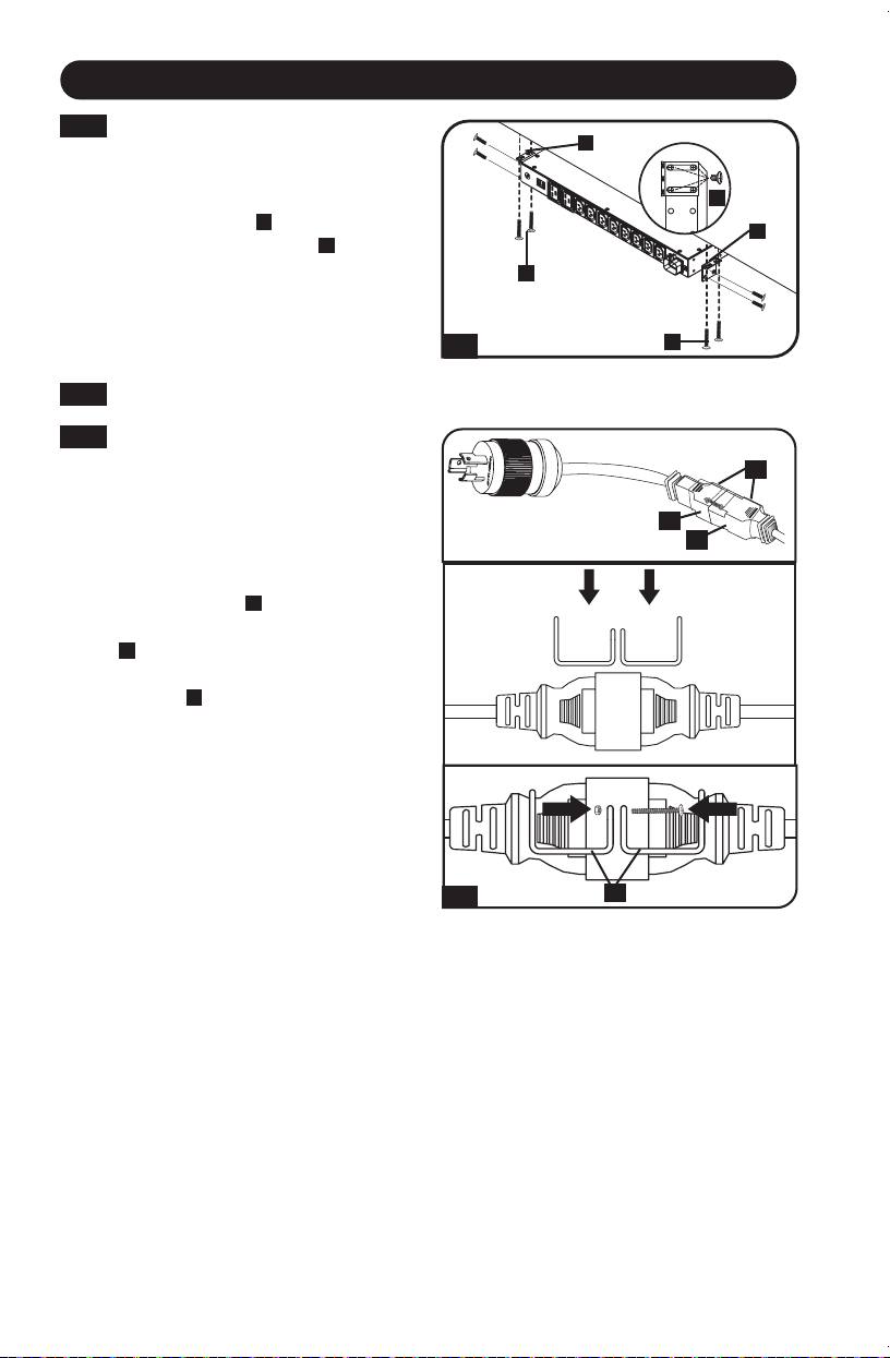
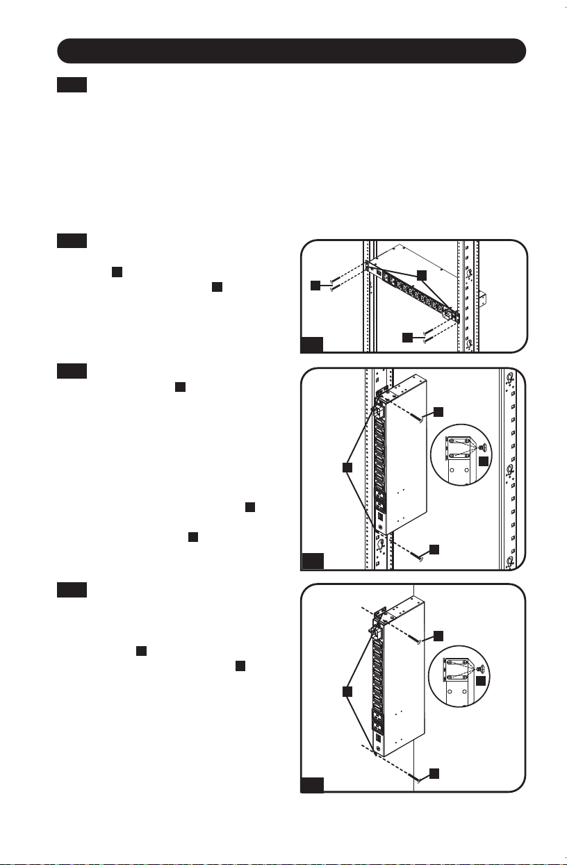
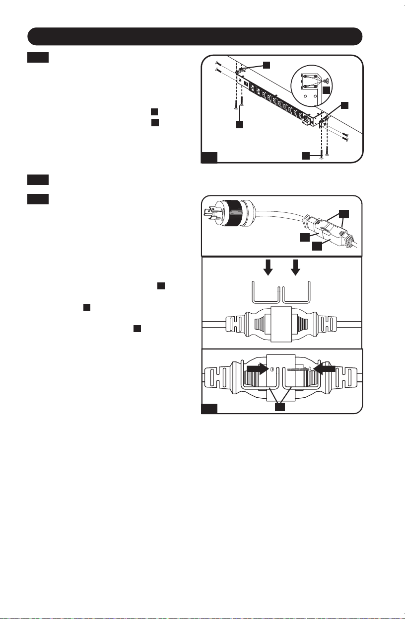
1-4
Under-Counter Installation: After
repeating Part 1 in Step 1-2, attach
the PDU to a stable mounting
surface by inserting four user-
supplied screws
A
through the
PDU mounting brackets
B
and into
secure mounting points on the
mounting surface.in the rack or
rack enclosure.
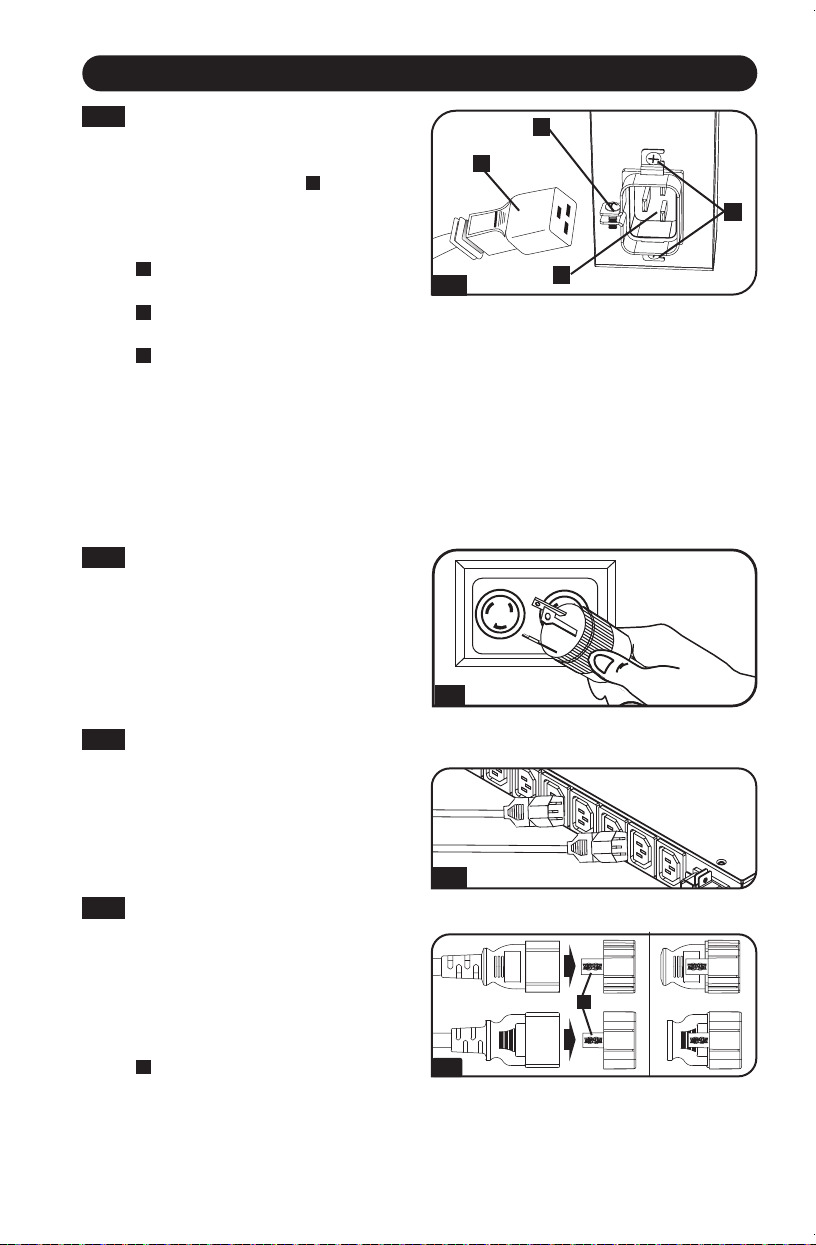
1-4
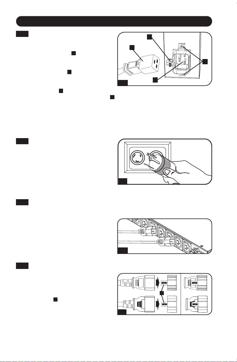
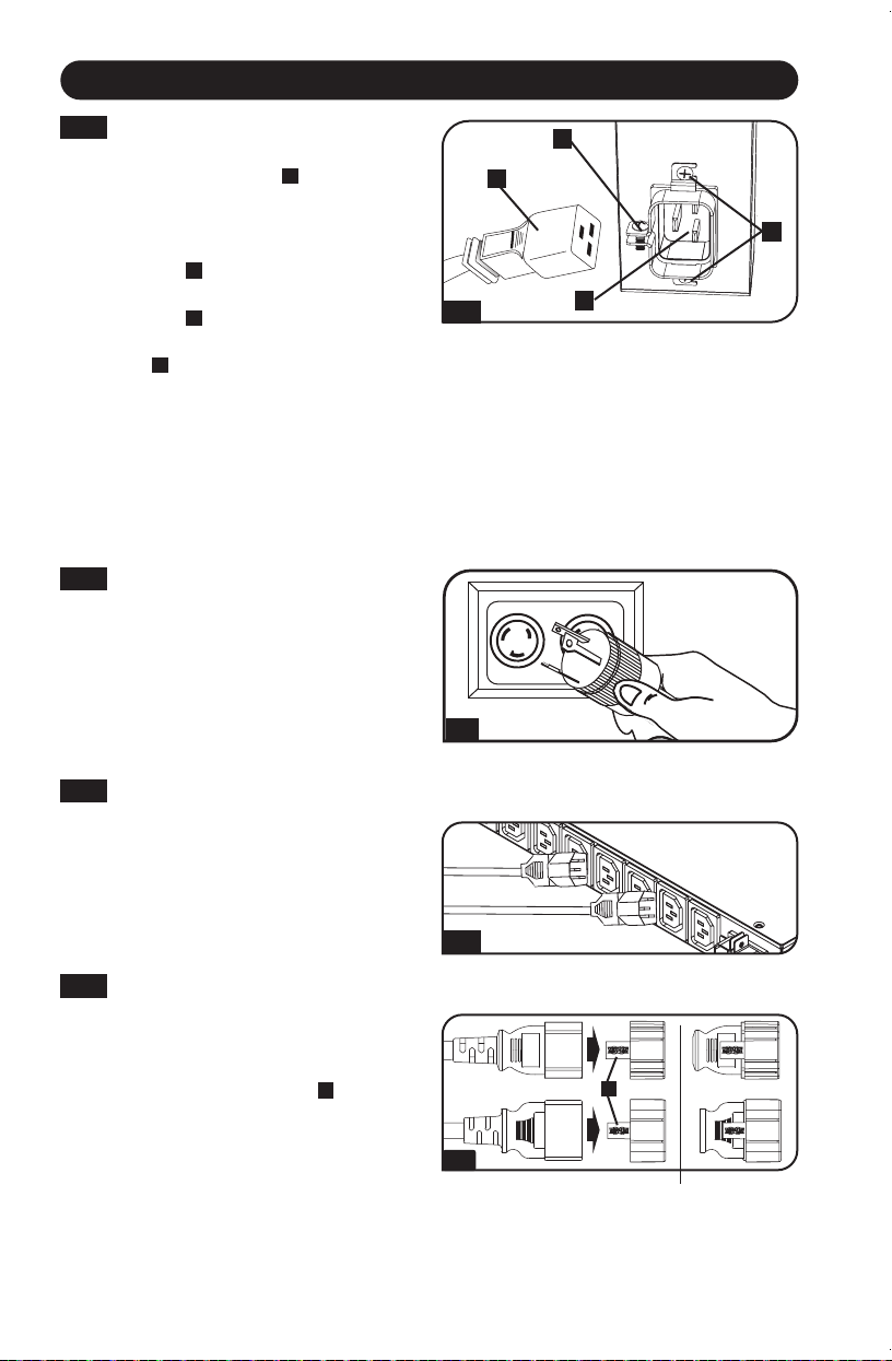
2-1
NEMA Adapter Connection
(Optional): This PDU includes a
plug adapter that adds a NEMA L6-
20P plug to the input power cord.
Use this adapter only if you will be
connecting the PDU to a NEMA L6-
20R outlet. Insert the IEC 60320
C19 connector
A
of the adapter
into the IEC 60320 C20 connector
B
of the input power cord. Secure
the connection with the retention
bracket
C
by using the included
bolts to fasten the two halves of the
bracket around the connection as
shown.
CAUTION: To avoid the risk of electric
shock, ensure that the Neutral (L2)
conductor has been identied before
connecting the PDU.
A
B
C
2-1
C
A
A
C
B
B
2
Establish a Power Connection
5
Installation
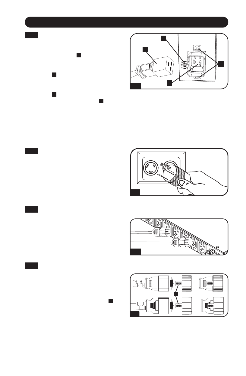
2-2
Input Power Cord Connection:
Attach the cable clamp to the PDU
using the included screws
A
.
Attach the included power cord
to the PDU by inserting the IEC
60320 C19 connector
B
of the
power cord into the cable clamp
and IEC 60320 C20 power inlet
C
located near the end of the PDU.
Install the included screw
D
on the
cable clamp to secure the power
cord connection. Connect the other
end of the input power cord to a
compatible source of AC power,
such as a UPS system, PDU or
utility outlet.
2-3
3
2-2
B
C
A
D
A
4
Note: When connecting the PDU, it should be provided with over-current protection and a
maximum 20A branch-rated over-current protection device.
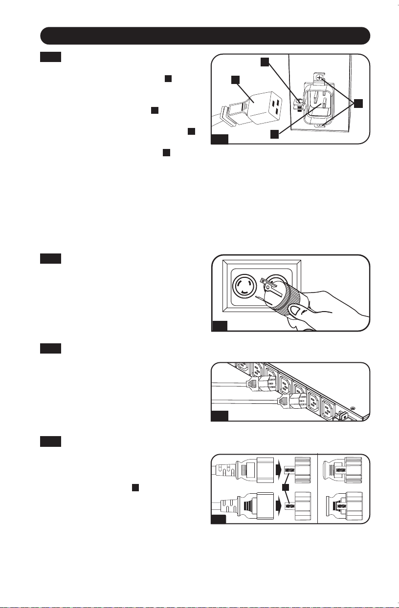
2-3
Attach the input plug of the PDU
to a grounded outlet: Insert the
plug directly into a grounded outlet
that does not share a circuit with a
heavy electrical load (such as an air
conditioner or refrigerator).
3
Attach equipment to the PDU
Do not exceed the load rating of
the PDU. The total electrical current
used by the PDU will be displayed
on the digital meter in amperes.
4
Optional Cord Retention Procedure
Use the included C14 sleeves to
secure plugs to receptacles. Attach
the sleeve to the plug, making sure
that the pull tabs
A
remain outside
theplugandthatthetissecure.
To unplug equipment properly, use
the pull tabs to remove the plug
and sleeve from the receptacle.
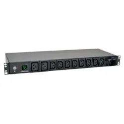
6
Features
LOAD (AMPS)
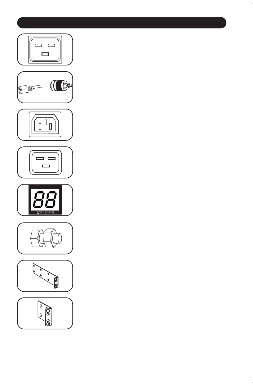
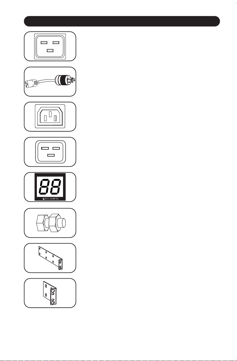
IEC-320-C20 Power Inlet: The IEC power inlet connects to
the included power cord or a compatible user-supplied power
cord.
AC Input Adapter: The adapter converts the AC input power
cord to a NEMA L6-20P plug. The included retention bracket
(not shown) secures the connection.
IEC-320-C13 Output Receptacles: These eight receptacles
distribute 208/230V AC power to connected equipment.
IEC-320-C19 Output Receptacles: These two receptacles
distribute 208/230V AC power to connected equipment.
Digital Load Meter (Ammeter): The digital load meter
displays the load in amps.
Grounding Lug: Use this screw to connect the PDU to ground.
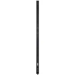
Longer 1U Mounting Brackets: Use these brackets to mount
the 1U PDU horizontally in a standard rack or rack enclosure.
The mounting depth can be adjusted by attaching the
brackets to different positions on the PDU.
Shorter 0U Mounting Brackets: Use these brackets to mount
thePDUina0Urack,wallorunder-countercongurationfor
1U PDU models.

7
LIMITED LIFETIME WARRANTY
Seller warrants this product, if used in accordance with all applicable instructions, to be free from original defects in material and
workmanship for its lifetime. If the product should prove defective in material or workmanship within that period, Seller will repair or
replace the product, at its sole discretion. Service under this Warranty can only be obtained by Buyer delivering or shipping the
product (with all shipping or delivery charges prepaid) to: Tripp Lite, 1111 W. 35th Street, Chicago, IL 60609. Seller will pay return
shipping charges. Call Tripp Lite at (773) 869-1234 before sending any equipment back for repair.
THIS WARRANTY DOES NOT APPLY TO NORMAL WEAR OR TO DAMAGE RESULTING FROM ACCIDENT, MISUSE, ABUSE OR NEGLECT.
SELLER MAKES NO EXPRESS WARRANTIES OTHER THAN THE WARRANTY EXPRESSLY SET FORTH HEREIN. EXCEPT TO THE EXTENT
PROHIBITED BY APPLICABLE LAW, ALL IMPLIED WARRANTIES, INCLUDING ALL WARRANTIES OF MERCHANTABILITY OR FITNESS,
ARE LIMITED IN DURATION TO THE WARRANTY PERIOD SET FORTH ABOVE; THIS WARRANTY EXPRESSLY EXCLUDES ALL INCIDENTAL
AND CONSEQUENTIAL DAMAGES. (Some states do not allow limitations on how long an implied warranty lasts, and some states do
not allow the exclusion or limitation of incidental or consequential damages, so the above limitations or exclusions may not apply to
you. This Warranty gives you specific legal rights, and you may have other rights which vary from jurisdiction to jurisdiction).
WARNING: The individual user should take care to determine prior to use whether this device is suitable, adequate or safe for the
use intended. Since individual applications are subject to great variation, the manufacturer makes no representation or warranty as
to the suitability or fitness of these devices for any specific application.
PRODUCT REGISTRATION
Visit www.tripplite.com/warranty today to register your new Tripp Lite product. You'll be automatically entered into a drawing for a
chance to win a FREE Tripp Lite product!*
* No purchase necessary. Void where prohibited. Some restrictions apply. See website for details.
Regulatory Compliance Identification Numbers
For the purpose of regulatory compliance certifications and identification, your Tripp Lite product has been assigned a unique series
number. The series number can be found on the product nameplate label, along with all required approval markings and
information. When requesting compliance information for this product, always refer to the series number. The series number should
not be confused with the marking name or model number of the product.
WEEE Compliance Information for Tripp Lite Customers and Recyclers (European Union)
Under the Waste Electrical and Electronic Equipment (WEEE) Directive and implementing regulations, when
customers buy new electrical and electronic equipment from Tripp Lite they are entitled to:
• Send old equipment for recycling on a one-for-one, like-for-like basis (this varies depending on the country)
• Send the new equipment back for recycling when this ultimately becomes waste
Tripp Lite has a policy of continuous improvement. Specifications are subject to change without notice.
Warranty and Product Registration
TrippLite.Eaton.com/support
23-08-127 93-3051_revC

8
Manual del propietario
PDU para montaje en rack
(bastidor) con amperímetro
Modelo: PDUMH20HV
(Número de Serie: AGPD7985)
Instrucciones de seguridad importantes 9
Instalación 10
Características 13
Garantía 14
English 1
Français 15
Русский 22
Deutsch 29
TrippLite.Eaton.com/support
Copyright © 2023 Tripp Lite. Todos los derechos reservados.

9
Instrucciones de seguridad importantes
GUARDE ESTAS INSTRUCCIONES
Este manual contiene instrucciones y advertencias que deben seguirse
durante la instalación, operación y almacenamiento
de este producto. De no seguirlas, se anulará la garantía del producto.
• El PDU proporciona la conveniencia de múltiples tomacorrientes, pero NO proporciona
protección contra sobretensión o ruido en la línea para los equipos conectados.
• El PDU está diseñada solo para uso en interiores en un entorno controlado lejos de
humedad excesiva, temperaturas extremas, contaminantes conductivos, polvo o luz
del sol directa.
• Mantiene la temperatura ambiente interior entre 0°C y 40°C.
•ElPDUdebeserinstaladosolamenteporuntécnicocalicado.
•NointenteinstalarelPDUenunasupercieinestableonosegura.
• Instale de acuerdo con los reglamentos eléctricos locales. Asegúrese de usar para
la instalación la protección adecuada contra sobrecorriente, de acuerdo con la
especicacióndelaclavijaodelequipo.
• Conecte el PDU a un tomacorriente que esté de acuerdo a los códigos locales
de construcción y que esté correctamente protegido contra corrientes excesivas,
cortocircuitos y fallas de conexión a tierra.
• Los tomacorrientes eléctricos que suministran energía al equipo deben instalarse
próximos al equipo y ser fácilmente accesibles.
• No conecte El PDU a un toma corriente que no esté a tierra o cables de extensión o
adaptadores que eliminen la conexión a tierra.
• Asegúrese de proporcionar un dispositivo local de desconexión, que sea fácilmente
accesible, en cualquier modelo que esté instalado permanentemente sin una clavija.
• Nunca intente instalar equipos eléctricos durante una tormenta eléctrica.
• El equipo individual conectado al PDU no debe consumir más corriente que la de la
especicacióndecadatomacorrienteindividualdelPDU.
• La carga total conectada al PDU no debe exceder la capacidad de carga máxima del
PDU.
•NointentemodicarelPDU,lasclavijasdeentradaoloscablesdealimentación.
• No perfore ni intente abrir ninguna parte del gabinete del PDU. No tiene partes a las
que el usuario pueda dar servicio.
• No intente usar el PDU si se daña cualquier parte.
• No se recomienda el uso de este equipo en aplicaciones de soporte de vida en donde
la falla de este equipo pueda consecuentemente causar la falla del equipo de soporte
devidaoafectarsignicativamentesuseguridadoefectividad.Nouseesteequipoen
presenciadeunamezclainamabledeanestésicosconaire,oxígenouóxidonitroso.
10
1
Determine la conguración de la instalación
EstePDUpermiteconguracionesdeinstalaciónenrack1Uy0U,instalación
enparedeinstalaciónbajoelmostrador.Elijaunaconguraciónysigalas
instrucciones de instalación apropiadas.
Nota: Independientemente de la conguración, el usuario debe determinar la idoneidad
de los materiales y accesorios así como de los procedimientos antes del montaje. La PDU
y el material incluido están diseñados para racks (bastidores) y cajas de rack (bastidor)
comunes, y pueden no ser apropiados para todas las aplicaciones.
Instalación
1-3
1-1
1-2
1-1
Instalación en bastidor de 1U:
Fije la PDU al bastidor insertando
cuatro tornillos suministrados
por el usuario
A
a través de los
soportes de montaje
B
de la PDU
en los agujeros de montaje del riel
del bastidor como se muestra.
1-2
Instalación en bastidor de 0U.
Parte 1: Retire los tornillos
C
que
janlossoportesdemontajeala
PDU, cambie la orientación de los
soportes como se muestra y fíjelos
nuevamente. Use solo los tornillos
incluidos o sus equivalentes
exactos(#6-32,1/4pulgada[6.35
mm] de cabeza plana). Parte 2: Fije
la PDU verticalmente insertando
dos o más tornillos suministrados
por el usuario
A
a través de los
soportes de montaje
B
de la PDU
en los puntos de montaje en el
bastidor o la caja del bastidor.
1-3
Instalación de pared: Después de
repetirlaParte1enpaso1-2,je
laPDUenunasupercieestable
de montaje insertando dos tornillos
suministrados por el usuario
A
a
través de los soportes de montaje
B
de la PDU en los puntos de
montajedelasupercie.
A
A
A
A
A
A
B
B
B
C
C

11
Instalación
1-4
Instalación debajo de mostrador:
DespuésderepetirlaParte1
enpaso1-2,jelaPDUenuna
supercieestabledemontaje
insertando cuatro tornillos
suministrados por el usuario
A
a
través de los soportes de montaje
B
de la PDU en los puntos de
montajedelasupercie.
1-4
2-1
Adaptador de conexión NEMA
(Opcional): La PDU incluye un
adaptador que incorpora una
clavija NEMA L6-20P al cable de
alimentación de entrada. Utilice
este adaptador solamente si va
a conectar la PDU a una toma de
corriente NEMA L6-20R. Inserte
elconectorIEC60320C19
A
del adaptador en el conector
IEC 60320 C20
B
del cable de
alimentación de entrada. Asegure
la conexión con la abrazadera de
retención
C
mediante los tornillos
que se incluyen para sujetar las
dos mitades de la abrazadera
alrededor de la conexión, como se
muestra.
PRECAUCIÓN: Con el n de evitar
riesgos de descarga eléctrica,
asegúrese de que el cable de tierra (L2)
ha sido identicado antes de conectar
la PDU.
A
B
C
2-1
C
A
A
C
B
B
2
Establezca una Conexión de Alimentación
12
Instalación
2-2
Conexión del Cable de
Alimentación: Fije la abrazadera
de cables a la PDU utilizando los
tornillos incluidos
A
. Instale el
cable de alimentación incluido
en el PDU insertando el conector
IEC60320C19
B
del cable de
alimentación en la abrazadera del
cable y la entrada de energía IEC
60320 C20
C
ubicada cerca del
2-3
3
2-2
B
C
A
D
A
4
extremo del PDU. Instale el tornillo
D
en la abrazadera del cable para asegurar
la conexión del cable de alimentación. Conecte el otro extremo del cable de
alimentación a una fuente compatible de energía de CA como un sistema UPS,
PDU o tomacorriente de la red pública.
Nota: Al conectar el PDU, debe estar equipado con protección contra sobrecorriente y un
dispositivo de protección contra sobrecorriente especicado para 20A máximo por ramal.
2-3
Conecte el enchufe de entrada de
la PDU a un contacto conectado
a tierra: Inserte el enchufe
directamente en una toma de
corriente alterna conectada a
tierra que no comparta el circuito
con alguna carga eléctrica pesada
(como un aire acondicionado o una
refrigeradora).
3
Conecte equipos a la PDU. Tenga cuidado de no exceder la
capacidad de carga de la PDU
La corriente eléctrica total usada
por la unidad de distribución de
potencia (PDU) será mostrada en el
medidor digital, en amperios.
4
Procedimientos Opcionales para Sujeción del Cable
UselosmanguitosplásticosC14
para asegurar las clavijas a los
tomacorrientes. Instale el manguito
a la clavija, garantizando que las
pestañas
A
permanezcan fuera de
laclavijayqueelajustesearme.
Para desenchufar correctamente
el equipo, use las pestañas para
retirar del tomacorriente la clavija y
el manguito.

13
Características
LOAD (AMPS)
Entrada de Alimentación IEC-320-C20: La entrada de
alimentación IEC se conecta al cable de alimentación incluido
o a un cable de alimentación suministrado por el usuario.
Adaptador de Entrada CA: El adaptador convierte el cable de
alimentación de entrada CA en una clavija NEMA L6-20P. La
abrazadera de retención (no se muestra) asegura la conexión.
Tomacorrientes de Salida IEC-320-C13: Estos
tomacorrientesdistribuyenenergíade208/230VCAal
equipo conectado.
Tomacorrientes de Salida IEC-320-C19: Estos
tomacorrientesdistribuyenenergíade208/230VCAal
equipo conectado.
Medidor Digital de Carga (Amperímetro): El medidor digital
de carga muestra la carga en amperes.
Oreja de tierra: Use este tornillo para conectar la PDU a
tierra.
Soportes Montaje de 1U Largos: Use estos soportes
paramontarelPDUde1Uhorizontalmenteenunbastidor
estándar o en un estante para bastidor. La profundidad del
montajepuedeajustarsejandolossoportesendiferentes
posiciones en el PDU.
Soportes de Montaje Cortos: Use estos soportes para
montarelPDUenunaconguraciónparabastidor0U,enla
paredobajoelescritorioparamodelosdePDUde1U.

14
GARANTÍA LIMITADA
El vendedor garantiza que este producto, si se emplea de acuerdo con todas las instrucciones aplicables, no tendrá defectos en
materiales ni mano de obra por un período de 2 años a partir de la fecha de compra. Si se verifica que el producto tiene defectos
en los materiales o en la mano de obra dentro de dicho período, el vendedor reparará o reemplazará el producto, a su sola
discreción. Sólo puede obtenerse servicio bajo esta garantía, entregando o despachando el producto (con todos los cargos de
despachooentregapagadosporadelantado)a:TrippLite,1111W.35thStreet,Chicago,IL60609USA.Elvendedorpagarálos
cargosdedespachodelretorno.Visitewww.tripplite.com/supportantesdeenviaralgúnequipoparareparación.
ESTA GARANTÍA NO SE APLICA AL DESGASTE NORMAL O A DAÑOS RESULTANTES DE UN ACCIDENTE, USO INADECUADO, MALTRATO
ONEGLIGENCIA.ELVENDEDORNOEXPRESANINGUNAOTRAGARANTÍADISTINTADELAESTABLECIDAENESTEDOCUMENTOEN
FORMAEXPLÍCITA.EXCEPTOHASTAELGRADOPROHIBIDOPORLASLEYESAPLICABLES,TODASLASGARANTÍASIMPLÍCITAS,
INCLUYENDOTODASLASGARANTÍASDECOMERCIABILIDADOIDONEIDAD,ESTÁNLIMITADASENDURACIÓNALPERÍODODE
GARANTÍAESTABLECIDOANTERIORMENTE;ESTAGARANTÍAEXCLUYEEXPRESAMENTETODOSLOSDAÑOSINCIDENTALESY
CONSECUENTES. (Algunos estados no permiten limitaciones sobre la duración de una garantía implícita, y algunos estados no
permiten la exclusión o limitación de daños incidentales o consecuentes, de modo que las limitaciones o exclusiones mencionadas
pueden no aplicarse a usted. Esta garantía le da derechos legales específicos, pero usted puede tener otros derechos que varían
de jurisdicción a jurisdicción.)
ADVERTENCIA:Elusuarioindividualdebeencargarsededeterminarantesdeusarlo,siestedispositivoesapropiado,adecuadoo
seguroparaelusoproyectado.Yaquelasaplicacionesindividualesestánsujetasagranvariación,elfabricantenodeclarani
garantiza la idoneidad o aptitud de estos dispositivos para ninguna aplicación específica.
Cumplimiento de las normas de los números de identificación
Para fines de identificación y certificación del cumplimiento de las normas, su producto Tripp Lite tiene asignado un número de
serie único. Puede encontrar el número de serie en la etiqueta de la placa de identificación del producto, junto con los símbolos de
aprobación e información requeridos. Al solicitar información sobre el cumplimiento de las normas para este producto, siempre
mencione el número de serie. El número de serie no debe ser confundido con el nombre de identificación ni con el número de
modelo del producto.
Información de sobre Cumplimiento de la WEEE para Clientes de Tripp Lite y Recicladores (Unión
Europea)
SegúnlaDirectivadeResiduosdeAparatosEléctricosyElectrónicos(WasteElectricalandElectronicEquipment,WEEE)
y sus reglamentos, cuando los clientes compran nuevos equipos eléctricos y electrónicos a Tripp Lite, tienen derecho a:
• Enviar equipos antiguos para reciclaje según una base de uno por uno, entre productos similares
(esto varía dependiendo del país)
• Enviar el equipo nuevo de vuelta para reciclaje cuando este se convierta finalmente en desecho
Tripp Lite tiene una política de mejoramiento continuo. Las especificaciones están sujetas a cambio sin previo aviso.
Garantía
TrippLite.Eaton.com/support
23-08-12793-3051_revC

15
Manuel du propriétaire
Unité de distribution
d’alimentation (PDU) en
bâti avec compteur
Modèle : PDUMH20HV
(Número de Série : AGPD7985)
Importantes consignes de sécurité 16
Installation 17
Caractéristiques 20
Garantie 21
English 1
Español 8
Русский 22
Deutsch 29
TrippLite.Eaton.com/support
Copyright © 2023 Tripp Lite. Tous droits réservés.

16
Importantes consignes de sécurité
CONSERVER CES DIRECTIVES
Ce manuel contient des instructions et des mises en garde que vous
devez respecter durant l’installation, l’utilisation et l’entreposage
de ce produit. Le non-respect de ces instructions et mises en garde
affecter la garantie du produit.
• La PDU fournit des prises multiples pratiques, mais elle ne FOURNIT PAS de protection
contre les surtensions ou les bruits de ligne pour l’équipement connecté.
• La PDU est conçue pour être utilisée à l’intérieur uniquement, dans un environnement
contrôlé, à l’écart de l’excès d’humidité, des températures extrêmes, des
contaminants conducteurs, de la poussière et de la lumière directe du soleil.
• Maintenir la température intérieure ambiante entre 0 °C et 40 °C.
•LaPDUdoitêtreinstalléeparuntechnicienqualiéseulement.
• Ne pas tenter de monter la PDU sur une surface précaire ou instable.
• Installer conformément aux codes locaux de l’électricité. S’assurer d’utiliser la bonne
protection contre les surintensités pour l’installation, conformément aux valeurs
nominalesdelacheetdel’équipement.
• Branchez la PDU à une prise de courant à une prise de courant qui est conforme aux
codes de bâtiment locaux et qui est dûment protégée contre les courants excessifs,
les courts-circuits et les défauts à la terre.
• Les prises électriques qui alimentent l’équipement doivent être installées à proximité
de l’équipement et être facilement accessibles.
• Ne pas connecter la PDU dans une prise non mise à la masse ou des rallonges
électriques ou des adaptateurs qui éliminent la connexion à la masse.
• S’assurer de fournir un dispositif de déconnexion local pour tous les modèles qui sont
installésenpermanencesanschefacilementaccessible.
• Ne jamais essayer d’installer un équipement électrique pendant un orage.
• L’équipement individuel connecté à la PDU ne doit pas excéder la charge nominale des
prises individuelles de la PDU.
• La charge totale connectée à la PDU ne doit pas excéder la charge nominale maximum
pour la PDU.
•NepastenterdemodierlaPDU,ycomprisleschesd’entréeetlescâbles
d’alimentation.
• Ne pas percer ou tenter d’ouvrir une quelconque partie du boîtier de la PDU. Il n’existe
aucune pièce réparable par l’utilisateur à l’intérieur.
• Ne pas tenter d’utiliser la PDU si une de ses pièces est endommagée.
• Il n’est pas recommandé d’utiliser cet équipement dans les applications de soutien
vital où une panne de cet équipement serait susceptible de causer une panne de
l’équipementdesoutienvitaloud’affectersérieusementsasécuritéousonefcacité.
Ne pas utiliser cet équipement dans un milieu où il existe un mélange anesthésique
inammableavecdel’air,del’oxygèneoudel’oxydenitreux.
17
1
Dénir la conguration de l’installation L’unité peut être
installé selon quatre congurations
CettePDUpeutaccueillirlescongurationsenbâti1Uet0U,muralesetsous
lecomptoir.Choisirunecongurationetsuivrelesinstructionsd’installation
appropriées.
Remarque : Sans tenir compte de la conguration, l’utilisateur doit déterminer la
compatibilité de la quincaillerie et les procédures avant d’effectuer l’installation. L’unité
PDU et la quincaillerie incluse sont conçues pour des types de bâti et boîtier courants et
peuvent ne pas convenir à toutes les applications.
Installation
1-3
1-1
1-2
1-1
Installation en baie 1U : Fixer la
PDU à la baie en insérant quatre
vis
A
fournies par l’utilisateur dans
lesbridesdesxation
B
de l’unité
etdanslestrousdexationdela
glissière de la baie comme indiqué.
1-2
Installation en baie 0U. 1e partie
: Retirer les vis
C
xantlesbrides
dexationàlaPDU,changer
l’orientation des brides comme
indiquéetlesxerànouveau.
Utiliser seulement les vis jointes
ou leur équivalent exact (N° 6-32,
têteplate1/4po[6,4mm])2e
partie : Fixer la PDU verticalement
en insérant deux vis ou plus
A
,
fournies par l’utilisateur dans les
bridesdexation
B
de l’unité et
danslespointsdexationdela
baie ou de son boîtier.
1-3
Installation murale : Après avoir
effectuéla1epartieenétape1-2,
xerlaPDUsurunesurfacede
xationstableeninsérantdeuxvis
ou plus
A
, fournies par l’utilisateur
danslesbridesdexation
B
de l’unité et dans des points de
xationsûrsdelasurface.
A
A
A
A
A
A
B
B
B
C
C
18
Installation
1-4
Installation sous un comptoir :
Aprèsavoireffectuéla1epartie
enétape1-2,xerlaPDUsur
unesurfacedexationstable
en insérant deux vis ou plus
A
,
fournies par l’utilisateur dans les
bridesdexation
B
de l’unité et
dansdespointsdexationsûrsde
la surface.
1-4
2-1
Branchement de l’adaptateur
NEMA (en option) : La PDU
comprend un adaptateur
permettant d’ajouter une
cheNEMAL6-20Paucordon
d’alimentation. N’utilisez cet
adaptateur que pour connecter
laPDUàunepriseNEMAL6-
20R. Insérez le connecteur
A
CEI
60320C19del’adaptateurdans
le connecteur
B
CEI60320C20du
cordon d’alimentation. Sécurisez
le branchement avec la pince
de retenue
C
en utilisant les vis
fournispourxerlesdeuxmoitiés
de la pince autour de la connexion,
comme illustré.
ATTENTION : Pour éviter tout risque
d’électrocution, veillez à identier
le connecteur neutre (L2) avant de
connecter la PDU.
A
B
C
2-1
C
A
A
C
B
B
2
Établir une connexion de l’alimentation
19
Installation
2-2
Connexion du cordon
d’alimentation d’entrée : Fixez le
serre-câble à la PDU en utilisant
les vis fournies
A
. Fixer le cordon
d’alimentation inclus à la PDU en
insérantleconnecteurCEI60320
C19
B
du cordon d’alimentation
dans la bride du câble et dans
l’entréed’alimentationCEI60320
C20
C
située près de l’extrémité
2-3
3
2-2
B
C
A
D
A
4
de la PDU. Installer la vis
D
sur la bride du câble pour maintenir la connexion
du cordon d’alimentation. Brancher l’autre extrémité du cordon d’alimentation
d’entrée à une source d’alimentation CA compatible, comme un onduleur, une
PDU ou une prise électrique.
Remarque : Lors du branchement de la PDU, elle devrait recevoir une protection contre les
surcharges et un dispositif de protection contre les surcharges d’une section nominale de
20 A maximum.
2-3
Fixer le che d’entrée de l’unité
PDU à une prise mise à la terre :
Insérerlachedirectementdans
une prise CA correctement mise
à la terre, qui ne partage pas de
circuit supportant une lourde
charge électrique (comme un
climatiseurouunréfrigérateur).
3
Fixer l’équipement à l’unité PDU
Faire attention de ne pas dépasser
la charge nominale de l’unité PDU.
La totalité du courant électrique
utiliséeparlaPDUseraafchéeen
ampères au compteur numérique.
4
Procédures de rétention du cordon en option
Utiliser les manchons en plastique
C14incluspourretenirlesches
aux prises. Fixer le manchon à
lacheenvousassurantque
les languettes de préhension
A
demeurentàl’extérieurdelache
et que l’ajustement est sécuritaire.
Pour débrancher correctement
l’équipement, utiliser les languettes
de préhension pour retirer la
cheetlemanchondelaprisede
courant.

20
Caractéristiques
LOAD (AMPS)
Entrée d’alimentation IEC-320-C20 : L’entrée d’alimentation
IECsebrancheaucordond’alimentationinclusouàun
cordon d’alimentation compatible fourni par l’utilisateur.
Adaptateur de courant alternatif : L’adaptateur convertit
le cordon d’alimentation en courant alternatif en une prise
NEMAL6-20P.Lesupportdexationinclus(nonmontré)
permetdexerlaconnexion.
Prises de sorties IEC-320-C13 : Ces prises distribuent une
alimentation208/230VCAàl’équipementbranché.
Prises de sorties IEC-320-C19 : Ces prises distribuent une
alimentation208/230VCAàl’équipementbranché.
Indicateur de charge (ampèremètre) numérique :
L’indicateurdechargenumériqueafchelachargeen
ampères.
Cosse de mise à la terre : Utiliser cette vis pour connecter
l’unité PDU à la terre.
Supports de xation (1U) longs : Utilisez ces supports pour
xerl’unitédedistribution(1U)horizontalementdansunbâti
ou un coffret standard. La profondeur de montage peut être
ajustéeenxantlessupportsdansdifférentespositionssur
l’unité.
Supports de xation (0U) courts : Utilisez ces supports pour
xerl’unitédedistributiondansunbâti0U,aumurousous
un comptoir.

21
GARANTIE LIMITÉE
Le vendeur garantit que ce produit, s’il est utilisé selon toutes les directives applicables, est exempt de défauts d’origine de
matériel et de main-d’oeuvre pour une période de 2 ans à partir de la date initiale d’achat. Si le produit s’avère défectueux en
matérielouenmain-d’oeuvredurantcettepériode,levendeurrépareraouremplaceraleproduitàsadiscrétion.Vouspouvez
obtenir un service selon cette garantie seulement en livrant ou en expédiant le produit (avec les frais d’expédition et de livraison
prépayés)à:TrippLite,1111W.35thStreet,Chicago,IL60609USA.Levendeurpaierailesfraisd’expéditionderetour.Visitez
www.tripplite.com/supportavantd’envoyerunéquipementpourréparations.
CETTEGARANTIENES’APPLIQUEPASÀL’USURENORMALEOUAUXDOMMAGESRÉSULTANTD’ACCIDENTS,DEMAUVAISUSAGE,
D’ABUSOUDENÉGLIGENCE.LEVENDEURN’OFFREAUCUNEGARANTIEEXPLICITEAUTREQUELAGARANTIEEXPRESSÉMENT
SIGNIFIÉEÀLAPRÉSENTE.EXCEPTÉSELONLESLIMITESDELALOIAPPLICABLE,TOUTESLESGARANTIESIMPLICITES,YCOMPRIS
TOUTESLESGARANTIESDEQUALITÉMARCHANDEOUDECONFORMITÉÀUNBESOINPARTICULIER,SONTLIMITÉESENDURÉEÀ
LAPÉRIODEDEGARANTIEÉNONCÉECIDESSUSETCETTEGARANTIEEXCLUEEXPLICITEMENTTOURSLESDOMMAGES
ACCESSOIRESOUCONSÉCUTIFS.Certainsétatsnepermettentpaslalimitationdeladuréed’unegarantieimpliciteetcertains
états ne permettent pas la limitation ou l’exclusion de dommages accessoires ou consécutifs, en conséquence, les limitations et
les exclusions ci dessus pourraient ne pas s’appliquer à vous. Cette garantie vous donne des droits légaux spécifiques et vous
pourriez avoir d’autres droits selon les juridictions.
MISEENGARDE:L’utilisateurdevraprendresoindedétermineravantdel’utilisersicetappareilconvient,estadéquatetsûrpour
l’usage prévu. Puisque les applications individuelles sont sujettes à de grandes variations, le fabricant ne fait aucune
représentation ni n’offre de garantie quand à l’applicabilité et à la conformité de ces appareils pour une application particulière.
Numéros d’identification de conformité aux règlements
Àdesfinsdecertificationetd’identificationdeconformitéauxrèglements,votreproduitTrippLiteareçuunnumérodesérie
unique. Ce numéro se retrouve sur la plaque signalétique du produit, avec les inscriptions et informations d’approbation requises.
Lors d’une demande d’information de conformité pour ce produit, utilisez toujours le numéro de série. Il ne doit pas être confondu
avec le nom de la marque ou le numéro de modèle du produit.
L’information de conformité WEEE pour les clients de Tripp Lite et recycleurs
(Union européenne)
Souslesdirectivesetrèglementsdedéchetd’équipementsélectriqueetélectronique(WasteElectricalandElectronic
Equipment,WEEE),lorsquelesclientsachètentlematérielélectriqueetélectroniqueneufdeTrippLiteilssont
autorisésà:
•Envoyerlevieuxmatérielpourlerecyclagesurunebasedeun-contre-unetennature(cecivarieselonlepays)
• Renvoyer le matériel neuf pour recyclage quand ceci devient éventuellement un rebut
La politique de Tripp Lite en est une d’amélioration continue. Les spécifications sont sujettes à changement sans préavis.
Garantie
TrippLite.Eaton.com/support
23-08-12793-3051_revC

22
Руководство пользователя
Стоечный PDU с измерителем
Модель: PDUMH20HV
(номер серии: AGPD7985)
Важные указания по технике безопасности 2
Установка 3
Функциональные возможности 6
Гарантийные обязательства 7
English 1
Español 8
Français 15
Deutsch 29
TrippLite.Eaton.com/support
Охраняется авторским правом © 2023 Tripp Lite. Перепечатка запрещается.

23
Важные указания по технике безопасности
СОХРАНИТЕ НАСТОЯЩИЕ УКАЗАНИЯ
В настоящем руководстве содержатся указания и предупреждения, которые
необходимо соблюдать в процессе установки, эксплуатации и хранения данного изделия.
Игнорирование этих указаний может привести к потере гарантии.
• Блок распределения питания (PDU) оснащен несколькими удобными розетками, но НЕ обеспечивает защиту
подключенного оборудования от выбросов напряжения и шумов в линии.
• PDU предназначен только для использования в закрытых помещениях с регулируемым микроклиматом вдали
от источников повышенной влажности, экстремальных температур, электропроводных загрязнителей, пыли и
прямого солнечного света.
• Поддерживайте температуру воздуха внутри помещения в диапазоне от 0°C до 40°C
• Установка PDU должна производиться только квалифицированным техническим специалистом.
• Не устанавливайте PDU на незакрепленной или неустойчивой поверхности.
• Установку следует производить в соответствии с требованиями национальных электротехнических нормативов.
Обязательно используйте подходящие для устанавливаемой системы устройства защиты от перегрузок по току
в соответствии с номиналами, указанными на разъемах/оборудовании.
• Подключите PDU к розетке, соответствующей принятым в вашей стране строительным нормам и надлежащим
образом защищенной от избыточных токов, коротких замыканий и замыканий на землю.
• Электрические розетки, через которые осуществляется электропитание оборудования, должны быть
установлены в легкодоступном месте вблизи него.
• Не подключайте PDU к незаземленной розетке, а также к удлинителям или переходникам, не имеющим
заземления.
• Любые модели, устанавливаемые на постоянной основе без легкодоступного штепсельного разъема, должны в
обязательном порядке оснащаться локальным устройством защитного отключения.
• Ни в коем случае не производите монтаж электрооборудования во время грозы.
• Ток, потребляемый отдельными элементами оборудования, подключаемыми к PDU, не должен превышать
номинал соответствующих розеток PDU.
• Суммарная нагрузка от потребителей, подключенных к PDU, не должна превышать его максимально
допустимую нагрузку.
• Не вносите изменений в конструкцию PDU, входных разъемов или кабелей питания.
• Не высверливайте отверстий в корпусе PDU и не пытайтесь вскрыть какую-либо его часть. Внутри него нет
деталей, обслуживаемых пользователем.
• Не используйте PDU в случае повреждения любой из его частей.
• Не рекомендуется использование данного оборудования в системах жизнеобеспечения, где его выход из строя
предположительно может привести к перебоям в работе оборудования жизнеобеспечения или в значительной
мере снизить его безопасность или эффективность. Не используйте данное оборудование в присутствии
воспламеняющейся анестетической смеси с воздухом, кислородом или закисью азота.
24
1
Определение установочной конфигурации
Данная модель PDU подходит для вертикального монтажа в стойку (высота 0U), монтажа в стойку
высотой 1U, настенного монтажа и монтажа под прилавком. Выберите одну из комплектаций и
выполните монтаж согласно соответствующей инструкции.
Примечание. Независимо от типа установочной конфигурации, пользователь должен установить пригодность
оснастки и предполагаемых процедур до начала монтажа. PDU и входящая в его комплект оснастка предназначены
для обычных типов шкафов и могут не подходить для всех целей применения. Установочные конфигурации могут
различаться в деталях.
Установка
1-3
1-1
1-2
1-1
Монтаж в стойку размером 1U:
прикрепите PDU к шкафу путем ввертывания
четырех винтов
A
(не входящих в комплект
поставки) через монтажные кронштейны
PDU
B
в монтажные отверстия шкафа, как
показано на рисунке.
1-2
Вертикальный монтаж (0U). Часть 1:
выверните винты
C
, обеспечивающие
крепление монтажных кронштейнов к
PDU, измените ориентацию кронштейнов,
как показано на рисунке, и установите их
обратно на свое место. Используйте только
винты, поставляемые производителем, или
их полный аналог (#6-32, 1/4” с потайной
головкой). Часть 2. Прикрепите PDU
вертикально путем ввертывания двух или
более винтов
A
(в комплект поставки не
входят) через монтажные кронштейны PDU
B
в монтажные отверстия стойки или шкафа.
1-3
Настенный монтаж: после повторения
действий, описанных в части 1 (шаг 1-2),
прикрепите PDU к устойчивой монтажной
поверхности путем ввертывания двух или
более винтов
A
(не входящих в комплект
поставки) через монтажные кронштейны PDU
B
в монтажные отверстия на монтажной
поверхности.
A
A
A
A
A
A
B
B
B
C
C
25
Установка
1-4
Монтаж под прилавком: после повторения
действий, описанных выше в части 1
(шаг 1-2), прикрепите PDU к устойчивой
монтажной поверхности путем ввертывания
четырех винтов
A
(не входящих в комплект
поставки) через монтажные кронштейны PDU
B
в монтажные отверстия на монтажной
поверхности в стойке или шкафу.
1-4
2-1
Переходник NEMA (опциональный):
данная модель PDU оснащается штепсель-
переходником, который обеспечивает
шнур питания дополнительным разъемом
типа NEMA L6-20P. Этот переходник следует
использовать только при подключении PDU к
розетке типа NEMA L6-20R. Вставьте разъем
IEC 60320 C19 (
A
) переходника в разъем
IEC 60320 C20 (
B
) входного шнура питания.
Зафиксируйте соединение с помощью зажима
для фиксации
C
, скрепив входящими
в комплект болтами две части зажима,
охватывающие соединение, как показано на
рисунке.
ВНИМАНИЕ! Во избежание опасности поражения
электрическим током необходимо распознать
нейтральный провод (L2) перед подключением
PDU.
A
B
C
2-1
C
A
A
C
B
B
2
Подключение электропитания
26
Установка
2-2
Подключение входного шнура питания:
прикрепите кабельный зажим к корпусу
PDU при помощи винтов
A
, входящих в
комплект.
Присоедините поставляемый в комплекте
шнур питания к PDU, вставив разъем IEC
60320 C19
B
шнура питания в кабельный
зажим и входной разъем питания IEC
60320 C20
C
, расположенный у края PDU.
Вверните поставляемый в комплекте
винт
D
в кабельный зажим для фиксации
подключенного шнура питания. Подсоедините
другой конец входного шнура питания
к совместимому источнику питания
переменного тока (например, к ИБП, PDU или
электрической розетке).
2-3
3
2-2
B
C
A
D
A
4
Примечание. Подключаемый PDU должен быть оснащен защитой от перегрузок по току и устройством защиты от
перегрузок по току номиналом не более 20 A.
2-3
Включите штепсельный разъем
входного кабеля PDU в заземленную
розетку электрической сети. Разъем
следует вставлять непосредственно в
заземленную розетку, не находящуюся в
общем контуре с большой электрической
нагрузкой (такой как кондиционер или
холодильник).
3
Подключение оборудования к PDU
Не превышайте номинальную нагрузку
PDU. Суммарный электрический ток,
потребляемый PDU, высвечивается на
индикаторе цифрового измерителя в
амперах.
4
Фиксация входного шнура (опционально)
Для фиксации вилок в розетках используйте
поставляемые в комплекте муфты под
разъемы C14. Прикрепите муфту к разъему,
убедившись в том, что язычки
A
остались
снаружи, а также в плотном прилегании
муфты. Для правильного отключения
оборудования от источника питания
вынимайте разъем с муфтой из розетки,
держась за язычки.
27
Функциональные возможности
LOAD (AMPS)
Входной разъем питания IEC-320-C20: входной разъем питания типа
IEC подключается к поставляемому в комплекте шнуру питания или к
приобретаемому отдельно шнуру питания, совместимому с ним.
Входной адаптер питания переменного тока: этот адаптер преобразует
входной шнур питания переменного тока в разъем NEMA L6-20P. Поставляемый
в комплекте зажим для фиксации (на рисунке не показан) обеспечивает
фиксацию соединения.
Выходные розетки IEC-320-C13: в штатном режиме работы эти 8 розеток
распределяют мощность переменного тока напряжением 208/230 В между
подключенными к ним элементами оборудования.
Выходные розетки IEC-320-C19: в штатном режиме работы эти 2 розетки
распределяют мощность переменного тока напряжением 208/230 В между
подключенными к ним элементами оборудования.
Цифровой измеритель нагрузки (амперметр): цифровой измеритель
нагрузки отображает значение нагрузки в амперах.
Клемма заземления: заземлите PDU с помощью этого винта.
Удлиненные монтажные кронштейны размером 1U: используйте эти
кронштейны для горизонтального монтажа PDU размером 1U в стандартную
стойку или шкаф. Монтажная глубина может регулироваться путем крепления
кронштейнов к другим точкам PDU.
Укороченные монтажные кронштейны для вертикального монтажа:
используйте эти кронштейны для вертикального монтажа PDU в стойку (0U), а
также на стену или под прилавок (для моделей PDU высотой 1U).

28
ОГРАНИЧЕННАЯ ПОЖИЗНЕННАЯ ГАРАНТИЯ
Продавец гарантирует отсутствие изначальных дефектов материала или изготовления в течение всего срока службы при условии его использования в соответствии со
всеми применимыми к нему указаниями. В случае проявления каких-либо дефектов материала или изготовления в течение указанного периода Продавец осуществляет
ремонт или замену данного изделия исключительно по своему усмотрению. Обслуживание по настоящей Гарантии производится только при условии доставки или
отправки Покупателем бракованного изделия (с предварительной оплатой всех расходов по его транспортировке или доставке) по адресу: Tripp Lite, 1111 W. 35th Street,
Chicago, IL 60609. Расходы по обратной транспортировке изделия оплачиваются Продавцом. Перед отправкой любого оборудования на ремонт необходимо обратиться в
компанию Tripp Lite по телефону (773) 869-1234.
ДЕЙСТВИЕ НАСТОЯЩЕЙ ГАРАНТИИ НЕ РАСПРОСТРАНЯЕТСЯ НА СЛУЧАИ ЕСТЕСТВЕННОГО ИЗНОСА ИЛИ ПОВРЕЖДЕНИЯ В РЕЗУЛЬТАТЕ АВАРИИ, НЕНАДЛЕЖАЩЕГО ИСПОЛЬЗОВАНИЯ,
НАРУШЕНИЯ ПРАВИЛ ЭКСПЛУАТАЦИИ ИЛИ ХАЛАТНОСТИ. ПРОДАВЕЦ НЕ ПРЕДОСТАВЛЯЕТ НИКАКИХ ЯВНО ВЫРАЖЕННЫХ ГАРАНТИЙ ЗА ИСКЛЮЧЕНИЕМ ПРЯМО ИЗЛОЖЕННОЙ В
НАСТОЯЩЕМ ДОКУМЕНТЕ. ЗА ИСКЛЮЧЕНИЕМ СЛУЧАЕВ, ЗАПРЕЩЕННЫХ ДЕЙСТВУЮЩИМ ЗАКОНОДАТЕЛЬСТВОМ, ВСЕ ПОДРАЗУМЕВАЕМЫЕ ГАРАНТИИ, ВКЛЮЧАЯ ВСЕ ГАРАНТИИ
ПРИГОДНОСТИ ДЛЯ ПРОДАЖИ ИЛИ ИСПОЛЬЗОВАНИЯ ПО НАЗНАЧЕНИЮ, ОГРАНИЧЕНЫ ПО ПРОДОЛЖИТЕЛЬНОСТИ ДЕЙСТВИЯ ВЫШЕУКАЗАННЫМ ГАРАНТИЙНЫМ СРОКОМ; ИЗ
НАСТОЯЩЕЙ ГАРАНТИИ ЯВНЫМ ОБРАЗОМ ИСКЛЮЧАЮТСЯ ВСЕ ПОБОЧНЫЕ, СЛУЧАЙНЫЕ И КОСВЕННЫЕ УБЫТКИ. (В некоторых штатах не допускается введение ограничений на
продолжительность действия тех или иных подразумеваемых гарантий, а в некоторых - исключение или ограничение размера побочных или косвенных убытков. В этих
случаях вышеизложенные ограничения или исключения могут на вас не распространяться. Настоящая Гарантия предоставляет вам конкретные юридические права, а
набор других ваших прав может быть различным в зависимости от юрисдикции).
ВНИМАНИЕ! До начала использования данного устройства пользователь должен убедиться в том, что оно является пригодным, соответствующим или безопасным для
предполагаемого применения. В связи с большим разнообразием конкретных применений производитель не дает каких-либо заверений или гарантий относительно
пригодности данных изделий для какого-либо конкретного применения или их соответствия каким-либо конкретным требованиям.
Информация по выполнению требований Директивы WEEE для покупателей и переработчиков продукции компании Tripp Lite
(являющихся резидентами Европейского союза)
Согласно положениям Директивы об утилизации отходов электрического и электронного оборудования (WEEE) и исполнительных распоряжений по ее
применению, при покупке потребителями нового электрического или электронного оборудования производства компании Tripp Lite они получают
право на:
• Продажу старого оборудования по принципу “один за один” и/или на эквивалентной основе (в зависимости от конкретной страны)
• Отправку нового оборудования на переработку после окончательной выработки его ресурса
Компания Tripp Lite постоянно совершенствует свою продукцию. В связи с этим возможно изменение технических характеристик без предварительного уведомления.
Гарантийные обязательства
TrippLite.Eaton.com/support
23-08-127 93-3051_revC

29
Betriebsanleitung
Metered Rack-PDU
Modell: PDUMH20HV
(Seriennummer: AGPD7985)
Wichtige Sicherheitshinweise 30
Installation 31
Eigenschaften 34
Garantie 35
English 1
Español 8
Français 15
Русский 22
TrippLite.Eaton.com/support
Copyright © 2023 Tripp Lite. Alle Rechte vorbehalten.

30
Wichtige Sicherheitshinweise
BITTE BEWAHREN SIE DIESE ANLEITUNG AUF
Die vorliegende Betriebsanleitung enthält Anweisungen und
Warnhinweise, die bei Installation, Betrieb und Lagerung des hierin
beschriebenen Produkts befolgt werden sollten. Die Nichtbeachtung
dieser Anweisungen kann Ihre Garantie beeinträchtigen.
• Die PDU bietet den Komfort von mehreren Steckdosen, aber KEINEN Überspannungs-
oder Leitungsrauschschutz für angeschlossene Geräte.
• Die PDU ist nur für den Gebrauch in Innenräumen in einer kontrollierten Umgebung, fern
von übermäßiger Feuchtigkeit, extremen Temperaturen, leitfähigen Verunreinigungen,
Staub oder direktem Sonnenlicht bestimmt.
• Halten Sie die Raumtemperatur zwischen 0 °C und 40 °C
•DiePDUdarfnurvoneinemqualiziertenTechnikerinstalliertwerden.
•VersuchenSienicht,diePDUaufeinernichtabgesichertenoderinstabilenOberächezu
montieren.
• Installieren Sie die PDU gemäß den Vorgaben der nationalen Elektrorichtlinien. Stellen
Sie sicher, dass Sie für die Installation einen geeigneten Überstromschutz gemäß der
Stecker-/Geräteleistung verwenden.
• Schließen Sie die PDU an eine Steckdose an, die den örtlichen Bauvorschriften
entspricht und ausreichend gegen Überstrom, Kurzschluss und Erdschluss geschützt ist.
• Die Netzsteckdosen, die das Gerät mit Energie versorgen, sollten in der Nähe des Geräts
installiert werden und einfach zugänglich sein.
• Schließen Sie die PDU nicht an eine nicht ungeerdete Steckdose, an Verlängerungskabel
oder Adapter an, durch die der Masseanschluss unterbrochen wird.
• Stellen Sie ein lokales Trenngerät für alle Modelle bereit, die dauerhaft ohne leicht
zugänglichen Stecker installiert sind.
• Versuchen Sie niemals, elektrische Geräte während eines Gewitters anzuschließen.
• Einzelne Geräte, die an die PDU angeschlossen sind, sollten nicht mehr Strom ziehen als
den Nennwert der jeweiligen PDU-Steckdose.
• Die an die PDU angeschlossene Gesamtlast darf die maximale Lastangabe der PDU
nicht überschreiten.
•VersuchenSienicht,diePDU,EingangssteckeroderStromkabelzumodizieren.
• Bohren Sie das Gehäuse der PDU nicht an und versuchen Sie nicht, es zu öffnen. Es
sind keine Teile enthalten, die vom Benutzer gewartet werden können.
• Versuchen Sie nicht, die PDU zu verwenden, wenn ein Teil davon beschädigt ist.
• Die Verwendung dieses Geräts für Lebenserhaltungssysteme, in denen der Ausfall
des Geräts den Ausfall des Lebenserhaltungssystems verursachen oder dessen
Sicherheit beziehungsweise Wirksamkeit bedeutend beeinträchtigen kann, wird
nicht empfohlen. Verwenden Sie das Gerät nicht in der Nähe von entzündbaren
Narkosemittelmischungen, die Luft, Sauerstoff oder Stickstoffoxid enthalten.
31
1
Installationskonguration festlegen
Diese PDU unterstützt die 1HE- und 0HE-Rackmontage, Wandhalterung und die
InstallationunterdemTisch.WählenSieeineKongurationausundfolgenSieden
entsprechenden Installationsanweisungen.
Hinweis: Unabhängig von der Installationskonguration muss der Benutzer vor der
Montage die Eignung der Hardware und Verfahren überprüfen. Die PDU und die im
Lieferumfang enthaltene Hardware sind für gängige Rack-Typen und Rack-Gehäusetypen
ausgelegt und eignen sich möglicherweise nicht für alle Anwendungen. Die genauen
Montagekongurationen können variieren.
Installation
1-3
1-1
1-2
1-1
1HE-Rack-Installation: Befestigen
Sie die PDU am Rack, indem Sie vier
der vom Benutzer bereitgestellten
Schrauben
A
durch die PDU
Montagehalterungen
B
und in
die Befestigungsbohrungen der
Rackschiene drehen (siehe
Abbildung).
1-2
0HE-Rack-Installation: Teil 1:
Entfernen Sie die Schrauben
C
, mit
denen die Montagehalterungen an
der PDU befestigt sind, ändern Sie
die Ausrichtung der Halterungen
wie gezeigt und bringen Sie die
Halterungen wieder an. Verwenden
Sie ausschließlich die vom
Hersteller mitgelieferten Schrauben
oder deren exakte Entsprechung
(Flachkopfschraube, #6-32, 1/4
Zoll). Teil 2: Befestigen Sie die PDU
vertikal, indem Sie zwei oder mehr
der vom Benutzer bereitgestellten
Schrauben
A
durch die PDU
Montagehalterungen
B
und in die
Befestigungsbohrungen im Rack
oder Rack-Gehäuse drehen.
1-3
Wandmontage: Nachdem Sie Teil
1 in Schritt 1-2 wiederholt haben,
befestigen Sie die PDU an einer
stabilenMontageäche,indemSie
zwei oder mehr der vom Benutzer
bereitgestellte Schrauben
A
durch
die PDU-Montagehalterungen
B
und
in sichere Befestigungsbohrungen
aufderMontageächedrehen.
A
A
A
A
A
A
B
B
B
C
C
32
Installation
1-4
Installation unter dem Tisch:
Nachdem Sie Teil 1 in Schritt 1-2
wiederholt haben, befestigen Sie die
PDUaneinerstabilenMontageäche,
indem Sie vier der vom Benutzer
bereitgestellte Schrauben
A
durch die
PDU Montagehalterungen
B
und in
sichere Befestigungsbohrungen auf
derMontageächeindasRackoder
Rack-Gehäuse drehen.
1-4
2-1
NEMA-Adapteranschluss
(optional): Diese PDU enthält
einen Steckadapter, der dem
Eingangsnetzkabel einen NEMA L6-
20P-Stecker hinzufügt. Verwenden
Sie diesen Adapter nur, wenn Sie
die PDU an eine NEMA L6-20R-
Steckdose anschließen. Stecken Sie
den IEC 60320 C19-Stecker
A
des
Adapters in den IEC 60320 C20-
Stecker
B
des Eingangsnetzkabels.
Sichern Sie die Verbindung mit der
Halteklammer, indem
C
Sie die
beiden Hälften der Klammer wie
abgebildet mit den mitgelieferten
Schrauben um die Verbindung
befestigen.
ACHTUNG: Um die Gefahr eines
Stromschlags zu verhindern, stellen Sie
sicher, dass der Nullleiter (L2) vor dem
Anschließen der PDU identiziert wurde.
A
B
C
2-1
C
A
A
C
B
B
2
Stromverbindung herstellen
33
Installation
2-2
Anschluss des Eingangsnetzkabels:
Befestigen Sie die Kabelklemme mit
den im Lieferumfang enthaltenen
Schrauben an der PDU
A
.
Befestigen Sie das im Lieferumfang
enthaltene Netzkabel an der PDU,
indem Sie den IEC 60320 C19-Stecker
B
des Netzkabels in die Kabelklemme
und den IEC 60320 C20-Stromeingang
C
am Ende der PDU einführen.
Bringen Sie die mitgelieferte Schraube
D
an der Kabelklemme an, um die
Netzkabelverbindung zu sichern.
Schließen Sie das andere Ende
des Eingangsnetzkabels an eine
kompatible Wechselstromquelle an, z.
B. ein USV-System, eine PDU oder eine
Steckdose.
2-3
3
2-2
B
C
A
D
A
4
Hinweis: Beim Anschließen der PDU sollte diese mit einem Überstromschutz und einem
Überstromschutzgerät mit einem Nennstrom von maximal 20 A ausgestattet sein.
2-3
Schließen Sie den Eingangsstecker
der PDU an eine geerdete
Steckdose an: Stecken Sie den
Stecker direkt in eine geerdete
Steckdose, die keinen Stromkreis mit
einer starken elektrischen Last teilt
(z. B. einer Klimaanlage oder einem
Kühlschrank).
3
Schließen Sie das Gerät an die PDU an.
Überschreiten Sie nicht die Nennlast
der PDU. Der gesamte verbrauchte
elektrische Strom der PDU wird auf
dem digitalen Messgerät in Ampere
angezeigt.
4
Optionale Kabelhalterung
Verwenden Sie die im Lieferumfang
enthaltenen C14-Hülsen, um Stecker
an Steckdosen zu befestigen.
Befestigen Sie die Hülse am Stecker
und achten Sie darauf, dass die
Zuglaschen außerhalb des Steckers
A
bleiben und der Stecker sicher
sitzt. Um Geräte ordnungsgemäß
auszustecken, verwenden Sie die
Zuglaschen, um den Stecker und die
Hülse aus der Steckdose zu entfernen.

34
Ausstattung
LOAD (AMPS)
IEC-320-C20-Stromeingang: Der IEC-Stromeingang wird
mit dem im Lieferumfang enthaltenen Netzkabel oder einem
kompatiblen, vom Benutzer bereitgestellten Netzkabel
verbunden.
AC-Eingangsadapter: Der Adapter wandelt das AC-Netzkabel
in einen NEMA L6-20P Stecker um. Die im Lieferumfang
enthaltene Halterung (nicht abgebildet) sichert die
Verbindung.
IEC-320-C13-Ausgangsbuchsen: Diese acht Steckdosen
verteilen 208/230V Wechselstrom auf die angeschlossenen
Geräte.
IEC-320-C19-Ausgangsbuchsen: Diese beiden Steckdosen
verteilen 208/230V Wechselstrom an die angeschlossenen
Geräte.
Digitales Ladungsmessgerät (Amperemeter): Das digitale
Ladungsmessgerät zeigt die Last in Ampere an.
Erdungsklemme: Verwenden Sie diese Schraube, um die PDU
mit der Erdung zu verbinden.
Längere 1HE-Montagehalterungen: Verwenden Sie diese
Halterungen, um die 1HE-PDU horizontal in einem Standard-
Rack oder Rack-Gehäuse zu montieren. Die Installationstiefe
kann angepasst werden, indem die Halterungen an
unterschiedlichen Positionen an der PDU installiert werden.
Kürzere 0HE-Montagehalterungen: Verwenden Sie diese
Halterungen, um die PDU in einem 0U-Rack, an der Wand
oder unter einem Tisch für 1HE-PDU-Modelle zu montieren.

35
LEBENSLANGE BESCHRÄNKTE GARANTIE
Der Verkäufer garantiert für die gesamte Produktlebensdauer, dass das Produkt weder Material- noch Herstellungsfehler aufweist,
wenn es gemäß aller zutreffenden Anweisungen verwendet wird. Wenn das Produkt in diesem Zeitraum Material- oder
Herstellungsfehler aufweist, kann der Verkäufer diese Fehler nach eigenem Ermessen beheben oder das Produkt ersetzen. Der
Service im Rahmen dieser Garantie kann nur in Anspruch genommen werden, wenn der Käufer das Produkt (mit allen Versand-
oder Versandkosten im Voraus bezahlt) an folgende Adresse liefert oder verschickt: Tripp Lite, 1111 W. 35th Street, Chicago, IL
60609. Der Verkäufer zahlt die Rücksendungsgebühren. Rufen Sie Tripp Lite unter (773) 869-1234 an, bevor Sie Geräte zur
Reparatur zurücksenden.
DIESE GARANTIE GILT NICHT FÜR NORMALEN VERSCHLEISS ODER FÜR SCHÄDEN, DIE DURCH UNFALL, MISSBRAUCH ODER
VERNACHLÄSSIGUNG ENTSTEHEN. AUSSER DEN NACHSTEHEND AUSDRÜCKLICH DARGELEGTEN GARANTIEBEDINGUNGEN
ÜBERNIMMT DER VERKÄUFER KEINERLEI GARANTIE. AUSSER WENN VON DEN GÜLTIGEN GESETZEN UNTERSAGT, SIND ALLE
IMPLIZIERTEN GARANTIEN, EINSCHLIESSLICH ALLER GARANTIEN FÜR DIE GEBRAUCHSTAUGLICHKEIT ODER EIGNUNG, AUF DIE
OBEN FESTGELEGTE GARANTIEDAUER BESCHRÄNKT. DIESE GARANTIE SCHLIESST AUSDRÜCKLICH ALLE FOLGESCHÄDEN UND
BEILÄUFIG ENTSTANDENEN SCHÄDEN AUS. (Einige Staaten erlauben keine Beschränkungen der Dauer einer stillschweigenden
Garantie, und einige Staaten erlauben keinen Ausschluss oder eine Beschränkung an Neben- oder Folgeschäden, sodass die oben
genannten Einschränkungen oder Ausschlüsse möglicherweise nicht auf Sie zutreffen. Diese Garantie gibt Ihnen bestimmte
Rechte. Sie haben jedoch möglicherweise andere Rechte, die abhängig von der Gerichtsbarkeit variieren können.)
WARNUNG: Der Benutzer muss vor der Verwendung überprüfen, ob das Gerät für den beabsichtigten Zweck geeignet und
angemessen ist und ob der Einsatz sicher ist. Da die Anwendungen variieren können, übernimmt der Hersteller keine Garantie
bezüglich der Eignung dieser Geräte für einen bestimmten Verwendungszweck.
Identifizierungsnummern für ordnungsrechtliche Compliance
Zum Zweck der Zertifizierung und Identifizierung der Einhaltung gesetzlicher Vorschriften wurde Ihrem Tripp Lite-Produkt eine
eindeutige Seriennummer zugewiesen. Die Seriennummer sowie alle erforderlichen Zulassungszeichen und Informationen finden
Sie auf dem Typenschild des Produkts. Wenn Sie Compliance-Informationen für dieses Produkt anfordern, geben Sie immer diese
Seriennummer an. Die Seriennummer sollte nicht mit dem Markierungsnamen oder der Modellnummer des Produkts verwechselt
werden.
WEEE-Compliance-Informationen für Tripp Lite-Kunden und Recycler (Europäische Union)
Gemäß der Richtlinie über Elektro- und Elektronik-Altgeräte (WEEE) und den entsprechenden
Durchführungsbestimmungen haben Kunden beim Kauf neuer elektrischer und elektronischer Geräte von Tripp Lite
Anspruch auf:
• Senden Sie alte Geräte zum Recycling auf einer Eins-zu-Eins-Basis (dies variiert je nach Land)
• Senden Sie die neuen Geräte zum Recycling zurück, wenn diese letztendlich zu Abfall werden.
Tripp Lite hat den Grundsatz, sich kontinuierlich zu verbessern. Spezifikationen können ohne Ankündigung geändert werden.
Garantie

36
TrippLite.Eaton.com/support
23-08-127 93-3051_revC