Loading ...
Loading ...
Loading ...
10
www.bromicheating.com
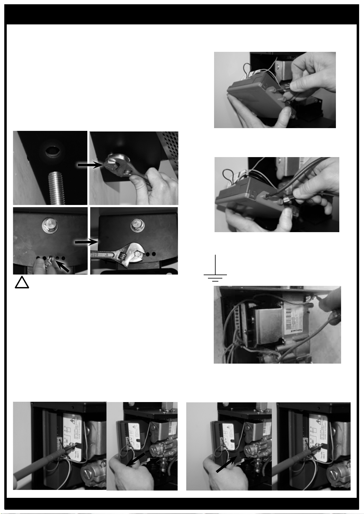
• Insert Black Ignitor Cable directly into control box
using 2.8mm spade connector, located on the side
of the controller
• Insert White Ionisation Cable directly into control
box using 4.75mm spade connector, located on the
side of the controller
• Insert Earth Terminal over earth tab, attached to
body of control housing and marked with Earth
Symbol
• Re-connect Honeywell control to the gas valve by
positioning the controllers inbuilt Molex plug over
the gas valve’s connector
INSTALLATION INSTRUCTIONS CONTINUED...
6. Insert Pivot Bolt
• Position Arm so that the rear hole’s on the mounting
arm and Control Housing are in alignment
• Insert Bolt and washer (as supplied) through Control
Housing and Mount Arm, using the hole located on
the bottom surface of the Control Housing, towards
the rear. Spanner tighten in place
• Select desired heater angle and insert the M6 Bolt
and washer (as supplied) through the bottom surface
of Control Housing into the mounting arm, using the
corresponding hole. (Heaters angle will be 0º, 10º or
20º). Spanner tighten in place
7. Connect the 3 wires from the heater by carefully following
the instructions below
For Honeywell Control
• Disconnect Honeywell control from Honeywell gas
valve by unscrewing retaining screw and pulling
away from gas valve
IMPORTANT
Electrical connections must be completed by trained and
authorized electrical technicians only!
!
Loading ...
Loading ...
Loading ...