
User Guide
HP Thin Client

© Copyright 2018 HP Development Company,
L.P.
Windows is either a registered trademark or
trademark of Microsoft Corporation in the
United States and/or other countries.
The information contained herein is subject to
change without notice. The only warranties for
HP products and services are set forth in the
express warranty statements accompanying
such products and services. Nothing herein
should be construed as constituting an
additional warranty. HP shall not be liable for
technical or editorial errors or omissions
contained herein.
First Edition: May 2018
Document Part Number: L18409-001
Product Notice
This user guide describes features that are
common to most models. Some features may
not be available on your computer.
Not all features are available in all editions or
versions of Windows. Systems may require
upgraded and/or separately purchased
hardware, drivers, software or BIOS update to
take full advantage of Windows functionality.
Windows 10 is automatically updated, which is
always enabled. ISP fees may apply and
additional requirements may apply over time
for updates. See http://www.microsoft.com.
To access the latest user guides, go to
http://www.hp.com/support, and follow the
instructions to nd your product. Then select
User Guides.
Software terms
By installing, copying, downloading, or
otherwise using any software product
preinstalled on this computer, you agree to be
bound by the terms of the HP End User License
Agreement (EULA). If you do not accept these
license terms, your sole remedy is to return the
entire unused product (hardware and software)
within 14 days for a full refund subject to the
refund policy of your seller.
For any further information or to request a full
refund of the price of the computer, please
contact your seller.

About This Guide
WARNING! Indicates a hazardous situation that, if not avoided, could result in bodily harm or loss of life.
CAUTION: Indicates a hazardous situation that, if not avoided, could result in damage to equipment or loss
of information.
IMPORTANT: Indicates information considered important but not hazard-related (for example, messages
related to property damage). A notice alerts the user that failure to follow a procedure exactly as described
could result in loss of data or in damage to hardware or software. Also contains essential information to
explain a concept or to complete a task.
NOTE: Contains additional information to emphasize or supplement important points of the main text.
TIP: Provides helpful hints for completing a task.
iii

iv About This Guide

Table of contents
1 Hardware Reference ...................................................................................................................................... 1
Product features .................................................................................................................................................... 1
Components ........................................................................................................................................ 2
Serial number location ........................................................................................................................ 3
Setup ...................................................................................................................................................................... 3
Warnings and cautions ........................................................................................................................ 3
Connecting the AC power cord ............................................................................................................ 4
Securing the thin client ....................................................................................................................... 4
Mounting and orienting the thin client ............................................................................................... 5
HP Quick Release mounting bracket ................................................................................. 5
Supported mounting options ............................................................................................ 8
Supported orientation and placement ........................................................................... 10
Non-supported placement ............................................................................................. 11
Routine thin client care ..................................................................................................................... 12
Hardware upgrades ............................................................................................................................................. 12
Warnings and cautions ...................................................................................................................... 12
Removing the access panel ............................................................................................................... 13
Removing and replacing the battery ................................................................................................ 14
2 Troubleshooting .......................................................................................................................................... 16
Computer Setup (F10) Utility, BIOS Settings ....................................................................................................... 16
Computer Setup (F10) Utility ............................................................................................................ 16
Using Computer Setup (F10) Utility ................................................................................ 16
Computer Setup—File .................................................................................................... 18
Computer Setup—Storage ............................................................................................. 19
Computer Setup—Security ............................................................................................. 20
Computer Setup—Power ................................................................................................ 21
Computer Setup—Advanced .......................................................................................... 22
Changing BIOS Settings from the HP BIOS Conguration Utility (HPBCU) .......................................................... 23
Updating or restoring a BIOS ............................................................................................................................... 25
Diagnostics and troubleshooting ........................................................................................................................ 26
LEDs ................................................................................................................................................... 26
Wake-on LAN ....................................................................................................................................................... 26
Power-on sequence ............................................................................................................................................. 27
Resetting the setup and power-on passwords ................................................................................................... 27
Power-on diagnostic tests ................................................................................................................................... 27
v

Interpreting POST diagnostic front panel LEDs and audible codes .................................................................... 28
Troubleshooting ................................................................................................................................................... 29
Basic troubleshooting ....................................................................................................................... 29
Diskless (no-ash) unit troubleshooting .......................................................................................... 30
Conguring a PXE server ..................................................................................................................................... 31
Using HP ThinUpdate to restore the image ......................................................................................................... 31
Device management ............................................................................................................................................ 32
Using HP PC Hardware Diagnostics (UEFI) ........................................................................................................... 32
Downloading HP PC Hardware Diagnostics (UEFI) to a USB device .................................................. 33
Power cord set requirements .............................................................................................................................. 33
General requirements ....................................................................................................................... 33
Japanese power cord requirements .................................................................................................. 34
Country-specic requirements ......................................................................................................... 34
Statement of volatility ......................................................................................................................................... 34
Available memory devices ................................................................................................................ 34
Specications ....................................................................................................................................................... 36
Appendix A Electrostatic discharge .................................................................................................................. 37
Preventing electrostatic damage ........................................................................................................................ 37
Grounding methods ............................................................................................................................................. 37
Appendix B Shipping information .................................................................................................................... 38
Shipping preparation ........................................................................................................................................... 38
Important service repair information .................................................................................................................. 38
Appendix C Accessibility ................................................................................................................................. 39
Supported assistive technologies ....................................................................................................................... 39
Contacting support .............................................................................................................................................. 39
Index ............................................................................................................................................................. 40
vi
1 Hardware Reference
Product features
This guide describes the features of the HP t430 Thin Client. For more information about the hardware and
software installed on this thin client, go to http://www.hp.com/go/quickspecs and search for this thin client.
Various options are available for your thin client. For more information about some of the available options,
go to the HP website at http://www.hp.com and search for your specic thin client.
Product features 1
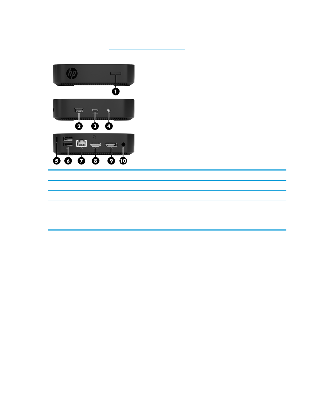
Components
For more information, go to http://www.hp.com/go/quickspecs and search for your specic thin client to nd
the QuickSpecs.
Item Component Item Component
1 Power button 6 USB Type-A SuperSpeed ports (2)
2 USB Type-A SuperSpeed port 7 RJ-45 (network) jack
3 USB Type-C dual role DisplayPort alternate mode port 8 HDMI port
4 Headset jack 9 Dual-Mode DisplayPort port
5 Security cable slot 10 Power connector
2 Chapter 1 Hardware Reference
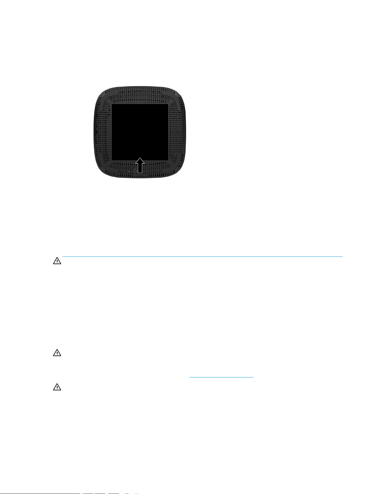
Serial number location
Every thin client includes a unique serial number located as shown in the following illustration. Have this
number available when contacting HP customer support for assistance.
Setup
Warnings and cautions
Before performing upgrades be sure to carefully read all of the applicable instructions, cautions, and
warnings in this guide.
WARNING! To reduce the risk of personal injury or equipment damage from electric shock, hot surfaces, or
re:
Install the thin client in a location where children are unlikely to be present.
Disconnect the AC power cord from the AC outlet and allow the internal system components to cool before
you touch them.
Do not plug telecommunications or telephone connectors into the network interface controller (NIC)
receptacles.
Do not disable the AC power cord grounding plug. The grounding plug is an important safety feature.
Plug the AC power cord into a grounded (earthed) AC outlet that is easily accessible at all times.
WARNING! To reduce the risk of serious injury, read the Safety & Comfort Guide provided with your user
guides. It describes proper workstation setup, and proper posture, health, and work habits for computer
users. The Safety & Comfort Guide also provides important electrical and mechanical safety information. The
Safety & Comfort Guide is available on the Web at http://www.hp.com/ergo.
WARNING! Energized parts inside.
Disconnect power to the equipment before removing the enclosure.
Replace and secure the enclosure before re-energizing the equipment.
Setup 3
CAUTION: Static electricity can damage the electrical components of the thin client or optional equipment.
Before beginning the following procedures, be sure that you are discharged of static electricity by briey
touching a grounded metal object. See Preventing electrostatic damage on page 37 for more information.
When the thin client is plugged into an AC power source, voltage is always applied to the system board. To
prevent damage to internal components, you must disconnect the AC power cord from the power source
before opening the thin client.
NOTE: An optional Quick Release mounting bracket is available from HP for mounting the thin client to a
wall, desk, or swing arm. When the mounting bracket is used, install the thin client with the I/O ports oriented
towards the ground.
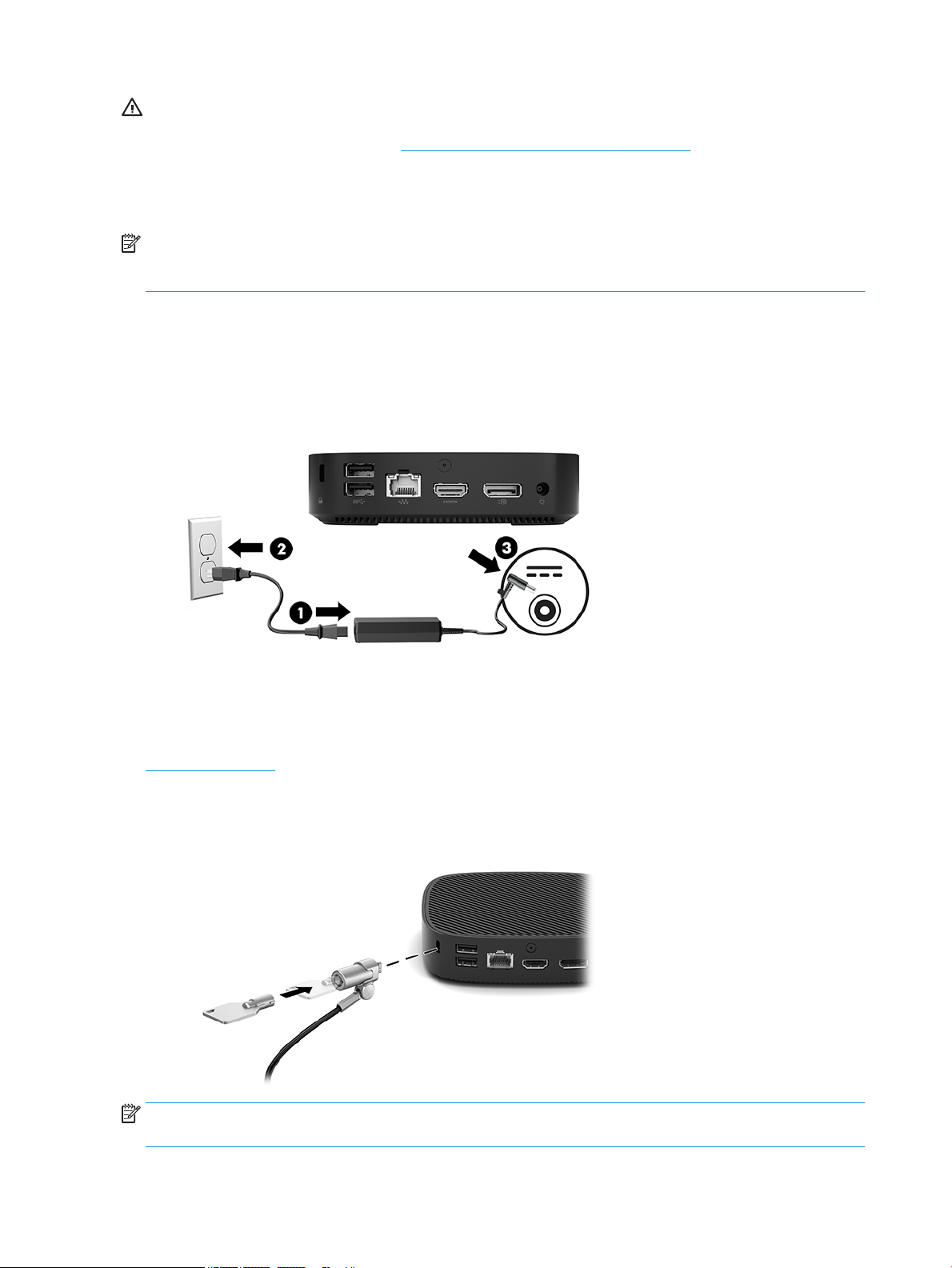
Connecting the AC power cord
1. Connect the power cord to the power adapter (1).
2. Connect the power cord to an AC outlet (2).
3. Connect the power adapter to the thin client (3).
Securing the thin client
Thin clients are designed to accept a security cable. The security cable prevents unauthorized removal of the
thin client and prevents access to the secure compartment. To order this option, go to the HP website at
http://www.hp.com and search for your specic thin client.
1. Locate the security cable slot on the back panel.
2. Insert the security cable lock into the slot, and then use the key to lock it.
NOTE: The security cable is designed to act as a deterrent, but it may not prevent the computer from being
mishandled or stolen.
4 Chapter 1 Hardware Reference
Mounting and orienting the thin client
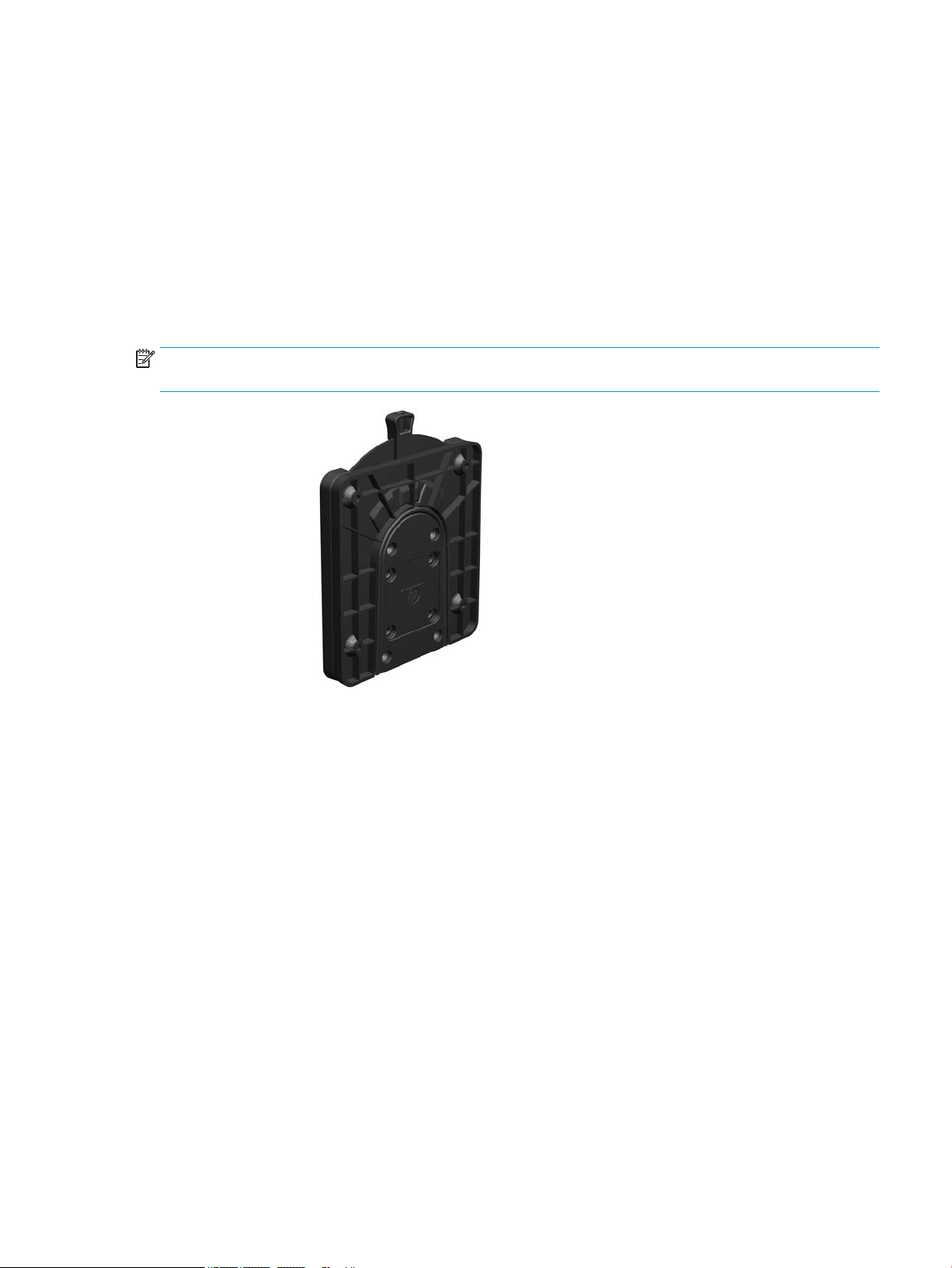
HP Quick Release mounting bracket
An optional Quick Release mounting bracket is available from HP for mounting the thin client to a wall, desk,
or swing arm. When the mounting bracket is used, install the thin client with the I/O ports oriented towards
the ground.
This unit has four mounting points that can be accessed by removing the rubber feet on the bottom. These
mounting points follow the VESA (Video Electronics Standards Association) standard, which provides
industry-standard mounting interfaces for Flat Displays (FDs), such as at panel monitors, at displays, and
at TVs. The HP Quick Release mounting bracket connects to the VESA-standard mounting points, allowing
you to mount the thin client in a variety of orientations.
NOTE: When mounting to a thin client, use the 10 mm screws supplied with the HP Quick Release mounting
bracket.
To use the HP Quick Release mounting bracket:
1. Lay the thin client upside down.
2. Remove the four rubber feet from the holes in the bottom of the thin client.
Setup 5
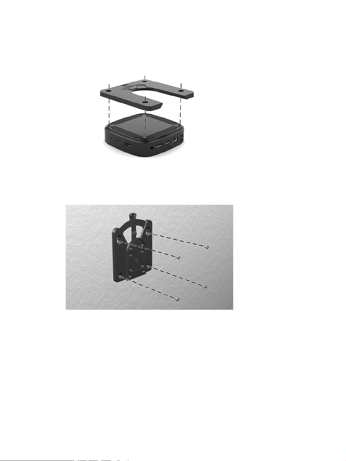
3. Position the HP Quick Release mounting bracket on the bottom of the thin client with the open end at
the rear edge. Use four 10 mm screws included in the mounting device kit to attach the HP Quick Release
mounting bracket, as shown in the following illustration.
4. Using four screws included in the mounting device kit, attach the other side of the HP Quick Release
mounting bracket to the device to which you will mount the thin client. Make sure the release lever
points upward.
6 Chapter 1 Hardware Reference
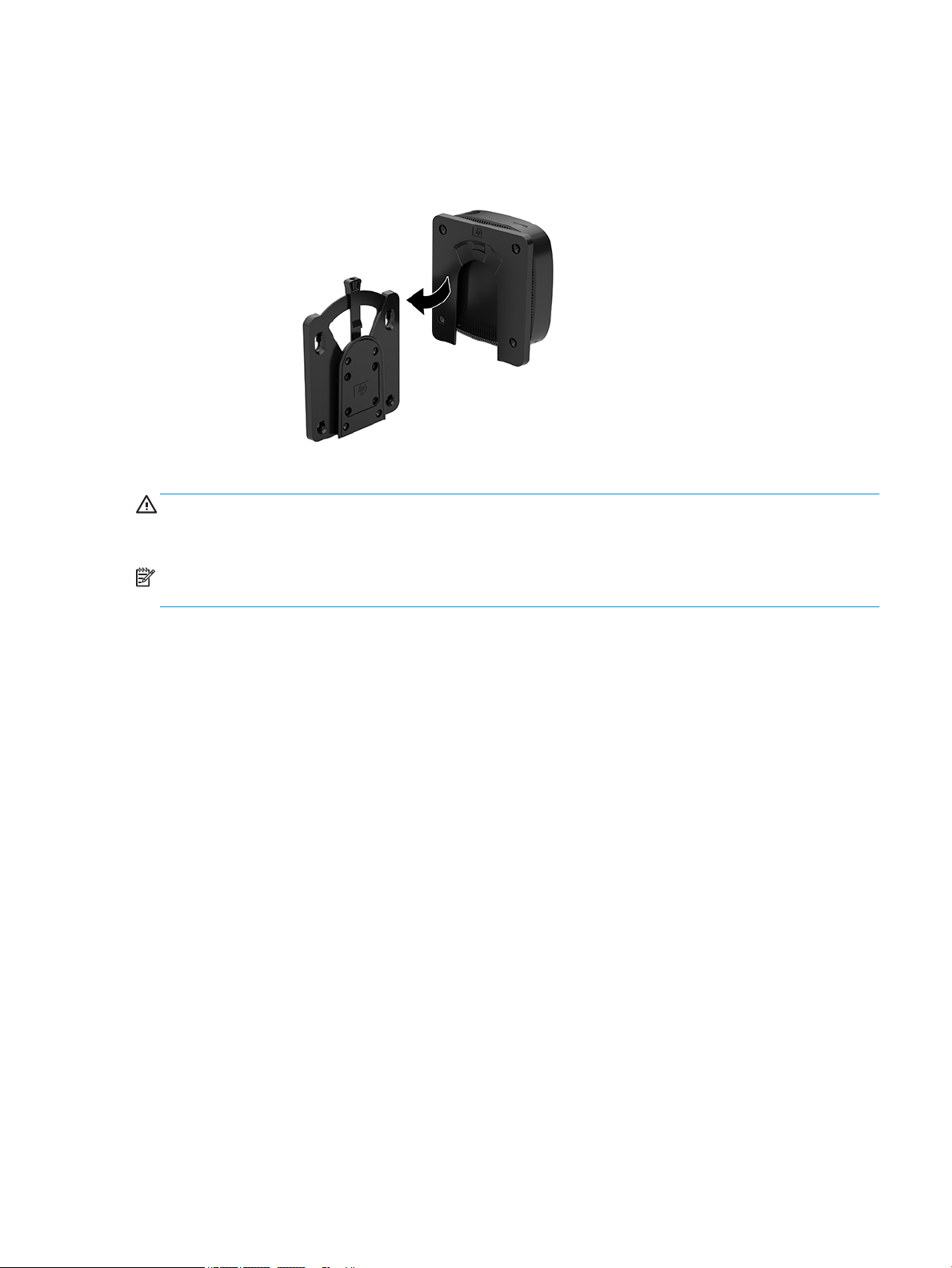
5. Slide the side of the mounting device attached to the thin client (1) over the other side of the mounting
device (2) on the device on which you want to mount the thin client. An audible 'click' indicates a secure
connection.
CAUTION: To ensure proper function of the HP Quick Release mounting bracket and a secure connection of
all components, make sure both the release lever on one side of the mounting device and the rounded
opening on the other side face upward.
NOTE: When attached, the HP Quick Release mounting bracket automatically locks in position. You only
need to slide the lever to one side to remove the thin client.
Setup 7
Supported mounting options
The following illustrations demonstrate some of the supported mounting options for the mounting bracket.
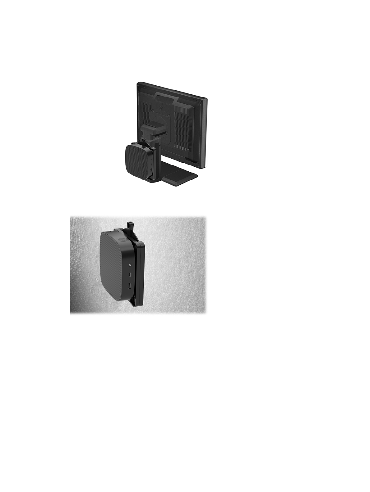
● On the back of a monitor:
● On a wall:
8 Chapter 1 Hardware Reference
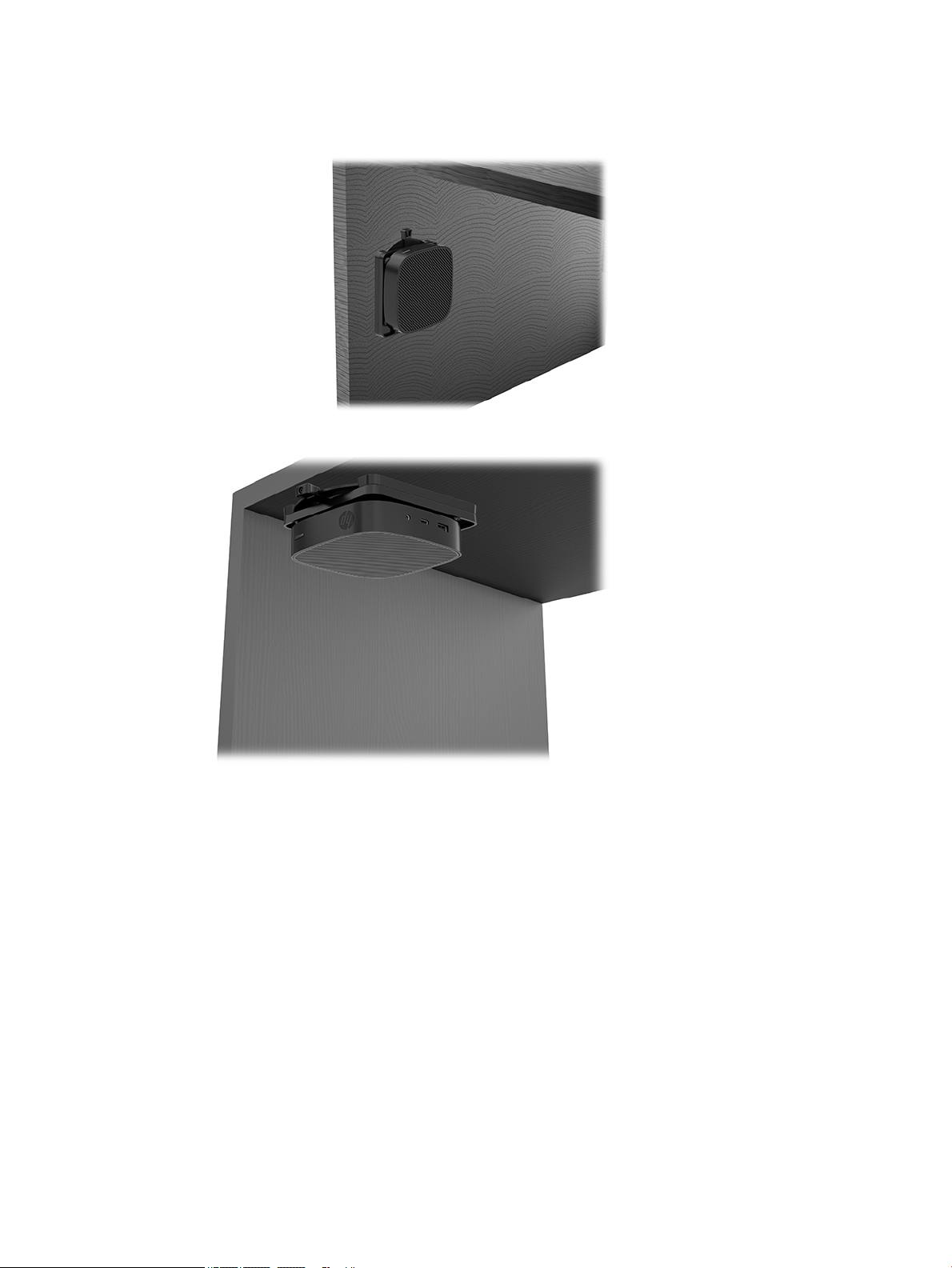
● Under a desk:
Setup 9
Supported orientation and placement
CAUTION: You must adhere to the HP-supported orientation to ensure your thin clients function properly.
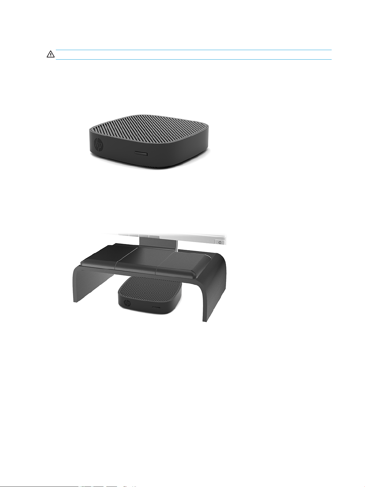
● HP supports the horizontal orientation for the thin client:
● The thin client may be placed under a monitor stand with at least 2.54 cm (1 in) clearance and 7.5 cm (3
in) for side cable routing:
10 Chapter 1 Hardware Reference
Non-supported placement
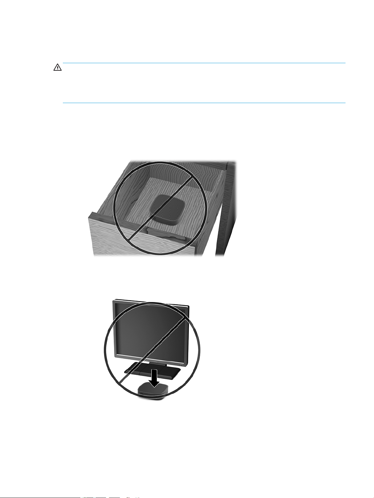
HP does not support the following placements for the thin client:
CAUTION: Non-supported placement of thin clients could result in operation failure and/or damage to the
devices.
Thin clients require proper ventilation to maintain operating temperature. Do not block the vents.
Install the thin client with the I/O ports oriented towards the ground.
Do not put thin clients in drawers or other sealed enclosures. Do not place a monitor or other object on top of
the thin client. Do not mount a thin client between the wall and a monitor. Thin clients require proper
ventilation to maintain operating temperatures.
● In a desk drawer:
● With a monitor on the thin client:
Setup 11

Routine thin client care
Use the following information to properly care for your thin client:
● Never operate the thin client with the outside panel removed.
● Keep the thin client away from excessive moisture, direct sunlight, and extreme heat and cold. For
information about the recommended temperature and humidity ranges for the thin client, go to
http://www.hp.com/go/quickspecs.
● Keep liquids away from the thin client and keyboard.
● Turn o the thin client and wipe the exterior with a soft, damp cloth as needed. Using cleaning products
may discolor or damage the nish.
Hardware upgrades
Warnings and cautions
Before performing upgrades be sure to carefully read all of the applicable instructions, cautions, and
warnings in this guide.
WARNING! To reduce the risk of personal injury or equipment damage from electric shock, hot surfaces, or
re:
Disconnect power to the equipment before removing the enclosure. Energized and moving parts are inside.
Allow the internal system components to cool before you touch them.
Replace and secure the enclosure before re-energizing the equipment.
Do not plug telecommunications or telephone connectors into the network interface controller (NIC)
receptacles.
Do not disable the AC power cord grounding plug. The grounding plug is an important safety feature.
Plug the AC power cord into a grounded (earthed) AC outlet that is easily accessible at all times.
WARNING! To reduce the risk of serious injury, read the Safety & Comfort Guide provided with your user
guides. It describes proper workstation setup, and proper posture, health, and work habits for computer
users. The Safety & Comfort Guide also provides important electrical and mechanical safety information. The
Safety & Comfort Guide is available on the Web at http://www.hp.com/ergo.
CAUTION: Static electricity can damage the electrical components of the thin client or optional equipment.
Before beginning the following procedures, be sure that you are discharged of static electricity by briey
touching a grounded metal object. See Preventing electrostatic damage on page 37 for more information.
When the thin client is plugged into an AC power source, voltage is always applied to the system board. To
prevent damage to internal components, you must disconnect the power cord from the power source before
opening the thin client.
12 Chapter 1 Hardware Reference
Removing the access panel
WARNING! To reduce the risk of personal injury or equipment damage from electric shock, hot surfaces, or
re, ALWAYS operate the thin client with the access panel in place. In addition to enhancing safety, the access
panel may provide important instructions and identication information, which may be lost if the access
panel is not used. DO NOT use any access panel except the one that is provided by HP for use with this thin
client.
Before removing the access panel, be sure that the thin client is turned o and the AC power cord is
disconnected from the AC outlet.
To remove the access panel:
1. Remove/disengage any security devices that prohibit opening the thin client.
2. Remove all removable media, such as USB ash drives, from the thin client.
3. Turn o the thin client properly through the operating system, and then turn o any external devices.
4. Disconnect the AC power cord from the AC outlet, and disconnect any external devices.
CAUTION: Regardless of the power-on state, voltage is always present on the system board as long as
the system is plugged into an active AC outlet. You must disconnect the AC power cord to avoid damage
to the internal components of the thin client.
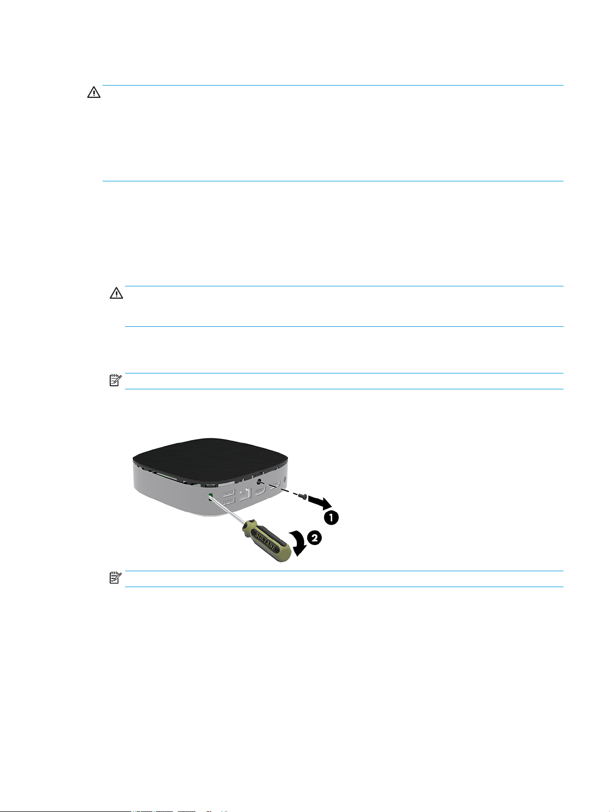
5. Lay the unit at on a stable surface with the top side up and the rear side facing you.
6. Use a Torx screwdriver to remove the Torx screw on the rear panel (1).
NOTE: Be sure to save the screw to reattach to the access panel.
7. Insert a screwdriver into the opening of the security cable slot and push up carefully to raise the corner
of the access panel (2).
NOTE: Be sure to save the screw to reattach the access panel.
Hardware upgrades 13
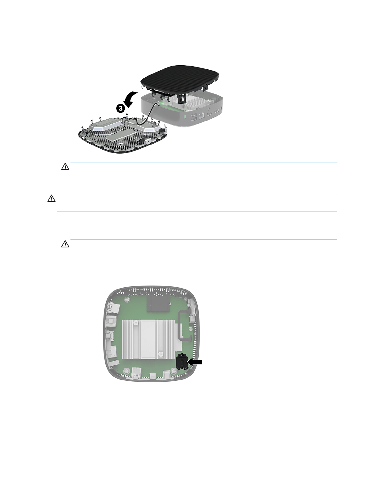
8. Lift the right side of the access panel and carefully rotate the panel o the thin client (3).
CAUTION: If the model includes a Wi-Fi adapter, be careful to avoid damage to the internal antenna.
Removing and replacing the battery
WARNING! Before removing the access panel, be sure that the thin client is turned o and the AC power cord
is disconnected from the AC outlet.
To remove and replace the battery:
1. Remove the thin client access panel. See Removing the access panel on page 13.
WARNING! To reduce risk of personal injury from hot surfaces, allow the internal system components
to cool before you touch them.
2. Locate the battery on the system board.
3. To release the battery from its holder, squeeze the metal clamp (1) that extends above one edge of the
battery.
14 Chapter 1 Hardware Reference
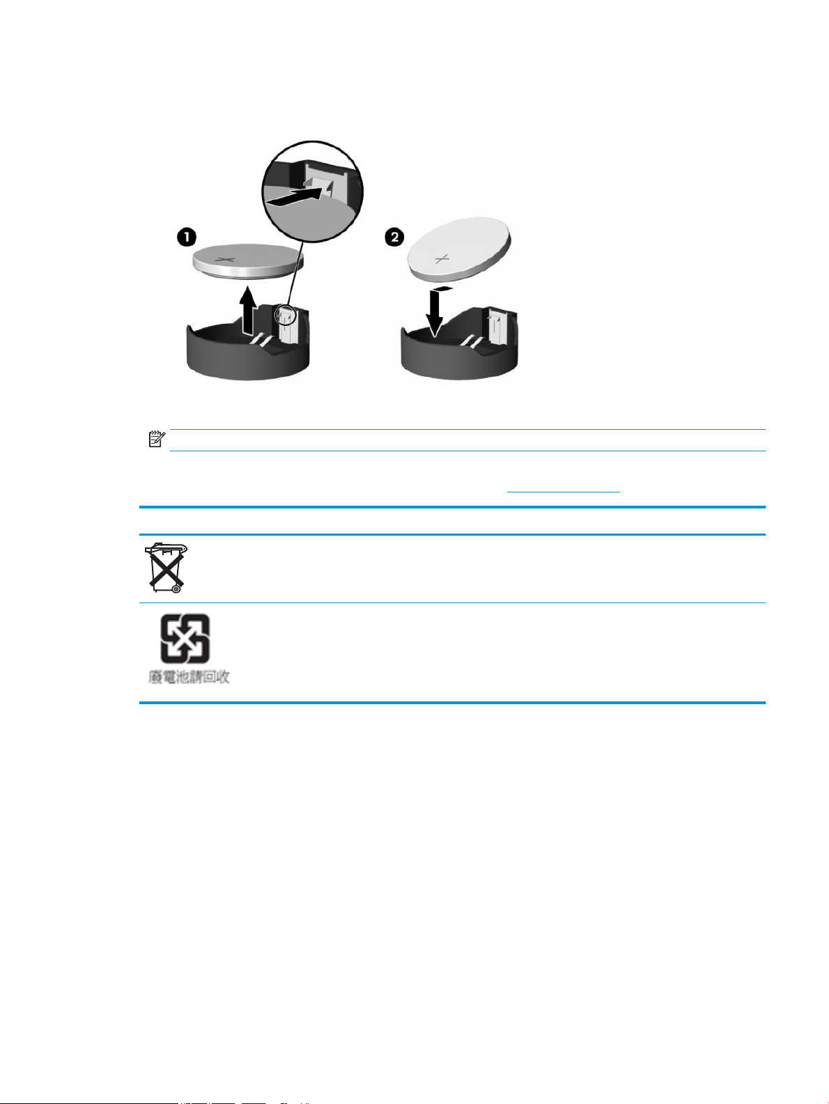
4. To insert the new battery, slide one edge of the replacement battery under the holder’s lip (2) with the
positive side up. Press the other edge down until the clamp snaps over the other edge of the battery.
5. Replace the access panel.
NOTE: Be sure to secure the access panel with the Torx screw.
HP encourages customers to recycle used electronic hardware, HP original print cartridges, and rechargeable
batteries. For more information about recycling programs, go to http://www.hp.com and search for “recycle.”
Icon Denition
Batteries, battery packs, and accumulators should not be disposed of together with the general household
waste. In order to forward them to recycling or proper disposal, please use the public collection system or
return them to HP, an authorized HP partner, or their agents.
The Taiwan EPA requires dry battery manufacturing or importing rms, in accordance with Article 15 or the
Waste Disposal Act, to indicate the recovery marks on the batteries used in sales, giveaways, or promotions.
Contact a qualied Taiwanese recycler for proper battery disposal.
Hardware upgrades 15

2 Troubleshooting
Computer Setup (F10) Utility, BIOS Settings
Computer Setup (F10) Utility
Use Computer Setup (F10) Utility to do the following:
● Change factory default settings.
● Set the system date and time.
● Set, view, change, or verify the system conguration, including settings for processor, graphics,
memory, audio, storage, communications, and input devices.
● Modify the boot order of bootable devices such as solid-state drives or USB ash media devices.
● Select POST Messages Enabled or Disabled to change the display status of Power-On Self-Test (POST)
messages. POST Messages Disabled suppresses most POST messages, such as memory count, product
name, and other non-error text messages. If a POST error occurs, the error is displayed regardless of the
mode selected. To manually switch to POST Messages Enabled during POST, press any key (except F1
through F12).
● Enter the Asset Tag or property identication number assigned by the company to this computer.
● Enable the power-on password prompt during system restarts (warm boots) as well as during power-on.
● Establish a setup password that controls access to the Computer Setup (F10) Utility and the settings
described in this section.
● Secure integrated I/O functionality, including the USB, audio, or embedded NIC, so that they cannot be
used until they are unsecured.
Using Computer Setup (F10) Utility
Computer Setup can be accessed only by turning the computer on or restarting the system. To access the
Computer Setup Utility menu, complete the following steps:
1. Turn on or restart the computer.
2. Press either esc or F10 while the “Press the ESC key for Startup Menu” message is displayed at the
bottom of the screen.
Pressing esc displays a menu that allows you to access dierent options available at startup.
NOTE: If you do not press esc or F10 at the appropriate time, you must restart the computer and again
press esc or F10 when the monitor light turns green to access the utility.
NOTE: You can select the language for most menus, settings, and messages using the Language
Selection option using the F8 key in Computer Setup.
3. If you pressed esc, press F10 to enter Computer Setup.
4. A choice of ve headings appears in the Computer Setup Utility menu: File, Storage, Security, Power, and
Advanced.
16 Chapter 2 Troubleshooting

5. Use the arrow (left and right) keys to select the appropriate heading. Use the arrow (up and down) keys
to select the option you want, and then press enter. To return to the Computer Setup Utility menu, press
esc.
6. To apply and save changes, select File > Save Changes and Exit.
● If you have made changes that you do not want applied, select Ignore Changes and Exit.
● To reset to factory settings, select Apply Defaults and Exit. This option will restore the original
factory system defaults.
CAUTION: To reduce the risk of corrupting the CMOS, do not turn the computer power o while the BIOS is
saving the Computer Setup (F10) changes. It is safe to turn o the computer only after exiting the F10 Setup
screen.
Heading Table
File Computer Setup—File on page 18
Storage Computer Setup—Storage on page 19
Security Computer Setup—Security on page 20
Power Computer Setup—Power on page 21
Advanced Computer Setup—Advanced on page 22
Computer Setup (F10) Utility, BIOS Settings 17

Computer Setup—File
NOTE: Support for specic Computer Setup options may vary depending on the hardware conguration.
Option Description
System Information Lists:
● Product name
● SKU number
● System Board CT Number
● Processor type
● Processor speed
● Processor stepping
● Cache size (L1/L2)
● Memory size
● Integrated MAC
● System BIOS
● Chassis serial number
● Asset tracking number
About Displays copyright notice.
Flash System BIOS Allows you to ash system BIOS from a USB recovery key.
Allows you to do the following:
● Launch HpBiosUpdate
● Update TPM FW
● Update USB Type C PD FW
Set Time and Date Allows you to set system time and date.
Default Setup Allows you to do the following:
● Save Current Settings as Default
● Restore Factory Settings as Default
Apply Defaults and Exit Loads the original factory system conguration settings for use by a subsequent “Apply Defaults and
Exit” action.
Ignore Changes and Exit Exits Computer Setup without applying or saving any changes.
Save Changes and Exit Saves changes to system conguration or default settings and exits Computer Setup.
18 Chapter 2 Troubleshooting

Computer Setup—Storage
Option Description
Device Conguration Lists all installed BIOS-controlled storage devices. When a device is selected, detailed information and
options are displayed. The following options may be presented:
Hard Disk: Size, model.
Storage Options USB Storage Boot
Allows you to set USB storage device default boot option in CSM/Legacy mode.
Boot Order Allows you to do the following:
● Specify the order in which EFI boot sources (such as an internal drive, USB hard drive, or USB optical
drive) are checked for a bootable operating system image. Each device on the list may be individually
excluded from or included for consideration as a bootable operating system source. EFI boot sources
always have precedence over legacy boot sources.
● Specify the order in which legacy boot sources (such as a network interface card, internal drive, or
USB optical drive) are checked for a bootable operating system image. Each device on the list may be
individually excluded from or included for consideration as a bootable operating system source.
● Specify the order of attached hard drives. The rst hard drive in the order will have priority in the
boot sequence and will be recognized as drive C (if any devices are attached).
NOTE: You can use F5 to disable individual boot items, as well as disable EFI boot and/or legacy boot.
MS-DOS drive lettering assignments may not apply after a non-MS-DOS operating system has started.
Shortcut to Temporarily Override Boot Order
To boot one time from a device other than the default device specied in Boot Order, restart the computer
and press esc (to access the boot menu) and then F9 (Boot Order), or only F9 (skipping the boot menu)
when the monitor light turns green. After POST is completed, a list of bootable devices is displayed. Use
the arrow keys to select the preferred bootable device and press enter. The computer then boots from the
selected non-default device for this one time.
Computer Setup (F10) Utility, BIOS Settings 19

Computer Setup—Security
NOTE: Support for specic Computer Setup options may vary depending on the hardware conguration.
Option Description
Setup Password Allows you to set and enable a setup (administrator) password.
NOTE: If the setup password is set, it is required to change Computer Setup options, ash the ROM, and
make changes to certain Plug and Play settings under Windows
®
.
Power-On Password Allows you to set and enable a power-on password. The power-on password prompt appears after a
power cycle or reboot. If the user does not enter the correct power-on password, the unit will not boot.
Password Options
(This selection appears
only if a power-on
password or setup
password is set.)
Allows you to enable/disable:
● Stringent Password—When set, enables a mode in which there is no physical bypass of the
password function. If enabled, removing the password jumper will be ignored.
● Password Prompt on F9 & F12—Default is enabled.
● Setup Browse Mode—Allows viewing, but not changing, the F10 Setup Options without entering
setup password. Default is enabled.
Device Security Allows you to set Device Available/Device Hidden (default is ‘Device Available’) for the following:
● System audio
● Network controller
● SSD
USB Security Allows you to set Enabled/Disabled (default is Enabled) for:
● Side USB Ports
– USB Port 2
– USB Port 4
● Rear USB Ports
– USB Port 0
– USB Port 1
Slot Security Allows you to disable the M.2 PCI Express slot. Default is Enabled.
● Slot # - M.2 PCIe x1
Network Boot Enables/disables the computer’s ability to boot from an operating system installed on a network server.
(Feature available on NIC models only; the network controller must be either a PCI expansion card or
embedded on the system board.) Default is enabled.
System IDs Allows you to set the following:
● Asset tag (18-byte identier)—A property identication number assigned by the company to the
computer.
● Ownership tag (80-byte identier)
System Security Provides these options:
● Virtualization Technology (enable/disable)—Controls the virtualization features of the processor.
Changing this setting requires turning the computer o and then back on. Default is disabled.
● TPM Device—Lets you set the Trusted Platform Module as available or hidden.
● TPM State—Select to enable the TPM.
20 Chapter 2 Troubleshooting

Option Description
● Clear TPM—Select to reset the TPM to an unowned state. After the TPM is cleared, it is also turned
o. To temporarily suspend TPM operations, turn the TPM o instead of clearing it.
CAUTION: Clearing the TPM resets it to factory defaults and turns it o. You will lose all created
keys and data protected by those keys.
Secure Boot
Conguration
The options on this setup page are only for Windows 10 and other operating systems that support Secure
Boot. Changing the default setting of the setup options on this page for operating systems that do not
support secure boot may prevent the system from booting successfully.
Legacy Support (enable/disable)—Enable or disable the legacy operating system support (Windows 10
IoT and HP Thin-Pro).
Secure Boot (enable/disable)—When the Legacy Support set to Disable, this item can be set to Enable.
This item is for Secure Boot ow control. Secure boot is possible only if system is run in user mode.
Key Management
● Clear Secure Boot Keys (Clear/Don’t Clear). Lets you clear the Secure Boot Key.
● Key ownership (HP keys/Customer keys). Lets you change the keys of dierent owners.
Fast Boot (Enable/Disable)—Enable Fast Boot causes system boot by initializing a minimal set of devices
which is required to launch the active boot option. This option has no eect for BBS boot options.
Computer Setup—Power
NOTE: Support for specic Computer Setup options may vary depending on the hardware conguration.
Option Description
OS Power Management Runtime Power Management (enable/disable)—Allows certain operating systems to reduce processor
voltage and frequency when the current software load does not require the full capabilities of the
processor. Default is enabled.
Idle Power Savings (Extended/Normal)—Extended/Normal. Allows certain operating systems to decrease
the processors power consumption when the processor is idle. Default is Extended.
Hardware Power
Management
S5 Maximum Power Savings—Turns o power to all nonessential hardware when system is o to meet
EUP Lot 6 requirement of less than 0.5 watt power usage. Default is disabled.
Computer Setup (F10) Utility, BIOS Settings 21

Computer Setup—Advanced
NOTE: Support for specic Computer Setup options may vary depending on the hardware conguration.
Option Heading
Power-On Options Allows you to set the following:
● POST messages (enable/disable)—Default is disabled.
● Press the ESC key for Startup Menu (Displayed/Hidden).
● After Power Loss (o/on/previous state)—Default is Power o. Set this option as follows:
● Power o—Causes the computer to remain powered o when power is restored.
● Power on—Causes the computer to power on automatically as soon as power is restored.
● Previous state—Causes the computer to power on automatically as soon as power is restored, if
it was on when power was lost.
NOTE: If you turn o power to the computer using the switch on a power strip, you will not be able to use
the suspend/sleep feature or the Remote Management features.
● POST Delay (in seconds)—Enabling this feature will add a user-specied delay to the POST process.
This delay is sometimes needed for hard disks on some PCI cards that spin up so slowly that they are
not ready to boot by the time POST is nished. The POST delay also gives you more time to select F10
to enter Computer (F10) Setup. Default is None.
● Remote Wakeup Boot Source (Local Hard Drive/Remote Server). Allows you to set the source from
which the computer gets its boot les when remotely awakened.
BIOS Power-On Allows you to set the computer to turn on automatically at a time you specify.
Bus Options On some models, allows you to enable or disable the following:
● PCI SERR# Generation. Default is enabled.
● PCI VGA Palette Snooping, which sets the VGA palette snooping bit in PCI conguration space; only
needed when more than one graphics controller is installed. Default is disabled.
Device Options ● Integrated Graphics (Auto/Force)—Use this option to manage integrated (UMA) graphics memory
allocation. The value you choose allocates memory permanently to graphics and is unavailable to the
operating system. For example, if you set this value to 512M on a system with 2 GB of RAM, the system
always allocates 512 MB for graphics and the other 1.5 GB for use by the BIOS and operating system.
Default is Auto, which sets UMA memory by the memory installed on the platform as follows:
– 2 GB: 128 MB
– 4 GB: 256 MB
If you select Force, the UMA Frame Buer Size option displays, which lets you set the UMA memory size
allocation between 128 MB and 512 MB.
● S5 Wake on LAN (enable/disable)
● Prompt for Power-On Password on Wake on LAN (enable/disable)
● Num Lock State at Power-On (o/on). Default is o.
Option ROM Launch
Policy
Allows you to set the following:
● Onboard NIC PXE Option ROMs (enable/disable)
22 Chapter 2 Troubleshooting

Changing BIOS Settings from the HP BIOS Conguration Utility
(HPBCU)
Some BIOS settings may be changed locally within the operating system without having to go through the F10
utility. This table identies the items that can be controlled with this method.
For more information about the HP BIOS Conguration Utility, see the HP BIOS Conguration Utility (BCU) User
Guide at www.hp.com.
BIOS setting Default value Other values
Language English Francais, Espanol, Deutsch, Italiano, Dansk, Suomi, Nederlands, Norsk,
Portugues, Svenska, Japanese, Simplied Chinese
Set Time 00:00 00:00:23:59
Set Day 01/01/2011 01/01/2011 to current date
Update USB Type-C PD FW Postpone Now
TPM2.0 FW Tool-less Update Disable Enable
TPM Physical Present Check Prompt No Prompt
Default Setup None Save Current Settings as Default; Restore Factory Settings as Default
Apply Defaults and Exit Disable Enable
Stringent Password Disable Enable
USB Storage Boot Before SSD After SSD
UEFI Boot Sources Windows Boot Manager USB Floppy/CD; USB hard drive
Legacy Boot Sources USB oppy/CD Hard drive
System Audio Enable Disable
Network Controller Enable Disable
SSD Enable Disable
Side USB Ports Enable Disable
USB Port 2, 4 Enable Disable
Rear USB Ports Enable Disable
USB Port 0, 1 Enable Disable
Slot # M.2 PCIe x1 Enable Disable
Network Boot Enable Disable
Asset Tracking Number
Ownership Tag
BIOS Update Disable Auto; Force
BIOS Image File Name
Data Execution Prevention Enable Disable
Virtualization Technology Disable Enable
TPM Device Available Hidden
Changing BIOS Settings from the HP BIOS Conguration Utility (HPBCU) 23

BIOS setting Default value Other values
TPM State Enable Disable
Clear TPM Do not reset Reset
Legacy Support Enable Disable (Note: The default value may vary, depending on the OS)
Secure Boot Disable Enable (Note: The default value may vary, depending on the OS)
Clear Secure Boot Keys Don’t Clear Clear
Key Ownership HP Keys Custom Keys
Fast Boot Disable Enable (Note: The default value may vary, depending on the OS)
Setup Browse Mode Enable Disable
Password Prompt on F9 &
F12
Enable Disable
Runtime Power Management Enable Disable
Idle Power Savings Extended Normal
S5 Maximum Power Savings Disable Enable
S5 Wake on LAN Enable Disable
POST Messages Disable Enable
Press the ESC key for Startup
Menu
Displayed Hidden
After Power Loss O On, Previous State
POST Delay (in seconds) None 5, 10, 15, 20, 60
Remote Wakeup Boot Source Local Hard Drive Remote Server
Prompt for Power-On
Password on Wake on LAN
Disable Enable
Power on Sunday – Saturday Disable Enable
BIOS Power on Time (hh:mm) 00:00 00:00:23:59
PCI SERR# Generation Enable Disable
PCI VGA Palette Snooping Disable Enable
Integrated Graphics Auto Disable, Force
UMA Frame Buer Size 256M 128M, 512M
Num Lock State at Power- On O On
PXE Option ROMs Enable Disable
24 Chapter 2 Troubleshooting

Updating or restoring a BIOS
HP Device Manager
HP Device Manager can be used to update the BIOS of a thin client. Customers can use a pre-built BIOS add-on
or can use the standard BIOS upgrade package along with an HP Device Manager File and Registry template.
For more information on HP Device Manager File and Registry templates, review the HP Device Manager User
Guide found at www.hp.com/go/hpdm.
Windows BIOS ashing
You can use the BIOS Flash Update SoftPaq to restore or upgrade the system BIOS. Several methods for
changing the BIOS rmware stored on your computer are available.
The BIOS executable is a utility designed to ash the System BIOS within a Microsoft Windows environment.
To display the available options for this utility, launch the executable le under the Microsoft Windows
environment.
You can run the BIOS executable with or without the USB storage device. If the system does not have a USB
storage device installed, the system reboots after performing a BIOS update in a Microsoft Windows
environment.
Linux BIOS ashing
All BIOS ashing under ThinPro 6.x and later utilizes tool-less BIOS updates, in which the BIOS updates itself.
Use the following comments to ash a Linux BIOS:
● hptc-bios-flash ImageName
Prepares the system to update the BIOS during the next restart. This command automatically copies the
les into the correct location and prompts you to restart the thin client. This command requires that the
tool-less update option in the BIOS settings is set to Auto. You can use hpt-bios-cfg to set the tool-
less update option in the BIOS.
● hptc-bios-flash –h
Displays a list of options.
BitLocker Drive Encryption / BIOS Measurements
If you have Windows BitLocker Drive Encryption (BDE) enabled on your system, we recommend that you
temporarily suspend BDE before updating the BIOS. You should also obtain your BDE recovery password or
recovery PIN before suspending BDE. After you ash the BIOS, you can resume BDE.
To make a change to BDE, select Start > Control Panel > BitLocker Drive Encryption, select Suspend
Protection or Resume Protection, and then select Yes.
As a general rule, updating the BIOS will modify measurement values stored in the Platform Conguration
Registers (PCRs) of the system's security module. Temporarily disable technologies that use these PCR values
to ascertain platform health (BDE is one such example) prior to ashing the BIOS. Once you update the BIOS,
re-enable the functions and restart the system so that you can take new measurements.
BootBlock Emergency Recovery Mode
In the event of a failed BIOS update (for example if power is lost while updating), the System BIOS may
become corrupted. BootBlock Emergency Recovery Mode detects this condition and automatically searches
the root directory of the hard drive and any USB media sources for a compatible binary image. Copy the binary
(.bin) le in the DOS Flash folder to the root of the desired storage device, and then power on the system.
Once the recovery process locates the binary image, it attempts the recovery process. The automatic recovery
continues until it successfully restores or updates the BIOS. If the system has a BIOS Setup password, you may
need to use the Startup Menu / Utility submenu to ash the BIOS manually after providing the password.
Updating or restoring a BIOS 25

Sometimes there are restrictions on which BIOS versions are allowed to be installed on a platform. If the BIOS
that was on the system had restrictions, then only allowable BIOS versions can be used for recovery.
Diagnostics and troubleshooting
LEDs
LED Status
Power LED is o When the unit is plugged into the wall socket and the power LED is o, the unit is powered o.
However, the network can trigger a Wake On LAN event in order to perform management functions.
Power LED is on Displays during boot sequence and while the unit is on. During boot sequence, hardware initialization is
processed and startup tests are performed on the following:
● Processor initialization
● Memory detection and initialization
● Video detection and initialization
NOTE: If one of the tests fails, the unit will simply stop, but the LED will stay on.
NOTE: After the video subsystem is initialized, anything that fails will have an error message.
NOTE: RJ-45 LEDs are located inside the RJ-45 connector on the top rear panel of the thin client. The LEDs are visible when the
connector is installed. Blinking green indicates network activity, and amber indicates a 100MB speed connection.
Wake-on LAN
Wake-on LAN (WOL) allows a computer to be turned on or resumed from the sleep or hibernation state by a
network message. You can enable or disable WOL in Computer Setup using the S5 Wake on LAN setting.
To enable or disable WOL:
1. Turn on or restart the computer.
2. Press either esc or F10 while the “Press the ESC key for Startup Menu” message is displayed at the
bottom of the screen.
NOTE: If you do not press esc or F10 at the appropriate time, you must restart the computer and again
press esc or F10 when the monitor light turns green.
3. If you pressed esc, press F10 to enter Computer Setup.
4. Navigate to Advanced > Device Options.
5. Set S5 Wake on LAN to either enabled or disabled.
6. Press F10 to accept any changes.
7. Select File > Save Changes and Exit.
IMPORTANT: The S5 Maximum Power Savings setting can aect wake-on LAN. If you enable this setting,
wake-on LAN is disabled. This setting is found in Computer Setup at Power > Hardware Management.
26 Chapter 2 Troubleshooting

Power-on sequence
At power-on, the ash boot block code initializes the hardware to a known state, then performs basic power-
on diagnostic tests to determine the integrity of the hardware. Initialization performs the following functions:
1. Initializes CPU and memory controller.
2. Initializes and congures all PCI devices.
3. Initializes video software.
4. Initializes the video to a known state.
5. Initializes USB devices to a known state.
6. Performs power-on diagnostics. For more information, see “Power-on diagnostic tests”.
7. The unit boots the operating system.
Resetting the setup and power-on passwords
You can reset the setup and power-on passwords as follows:
1. Turn o the computer and disconnect the power cord from the power outlet.
2. Remove the side access panel and the metal side cover.
3. Remove the password jumper from the system board header labeled PSWD/E49.
4. Replace the metal side cover and the side access panel.
5. Connect the computer to AC power, and then turn on the computer.
6. Turn o the computer and disconnect the power cord from the power outlet.
7. Remove the side access panel and the metal side cover.
8. Replace the password jumper.
9. Replace the metal side cover and the side access panel.
Power-on diagnostic tests
The Power-on diagnostics performs basic integrity tests of the hardware to determine its functionality and
conguration. If a diagnostic test fails during hardware initialization the unit simply stops. There are no
messages sent to video.
NOTE: You may try to restart the unit and run through the diagnostic tests a second time to conrm the rst
shutdown.
The following table lists the tests that are performed on the unit.
Table
2-1 Power-on diagnostic test
Test Description
Boot Block Checksum Tests boot block code for proper checksum value.
DRAM Performs a simple write/read pattern test of the rst 640k of memory.
Serial Port Performs a simple verication test of the serial port to determine if ports are present.
Timer Tests timer interrupt by using polling method.
Power-on sequence 27

Table 2-1 Power-on diagnostic test (continued)
Test Description
RTC CMOS battery Tests integrity of RTC CMOS battery.
NAND ash device Tests for proper NAND ash device ID present.
Interpreting POST diagnostic front panel LEDs and audible codes
This section covers the front panel LED codes as well as the audible codes that may occur before or during
POST that do not necessarily have an error code or text message associated with them.
WARNING! When the computer is plugged into an AC power source, voltage is always applied to the system
board. To reduce the risk of personal injury from electrical shock and/or hot surfaces, be sure to disconnect
the power cord from the wall outlet and allow the internal system components to cool before touching.
NOTE: Recommended actions in the following table are listed in the order in which they should be
performed.
Not all diagnostic lights and audible codes are available on all models.
Activity Beeps Possible Cause Recommended Action
White power LED is on. None Computer on. None
White power LED ashes every
two seconds.
None Computer in Suspend to
RAM mode (some models
only) or normal Suspend
mode.
No action required. Press any key or move the mouse
to wake the computer.
Red power LED solid red. None Processor thermal
protection activated:
OR
The heat sink assembly is
not properly attached to the
processor.
OR
The unit has vents blocked
or is in a location where the
ambient temperature is too
high.
1. Ensure that the computer air vents are not
blocked and the processor cooling fan is
plugged in and running, if equipped.
2. Contact an authorized reseller or service
provider.
Red power LED ashes eight
times, once every second,
followed by a two-second pause.
None Invalid ROM based on bad
checksum.
1. Reash the system ROM with the latest BIOS
image using the BIOS Recovery procedure.
2. Replace the system board.
28 Chapter 2 Troubleshooting

Troubleshooting
Basic troubleshooting
If the thin client is experiencing operating problems or will not power on, review the following items.
Issue Procedures
The thin client unit is experiencing operating
problems.
Ensure that the following connectors are securely plugged into the thin client unit:
Power connector, keyboard, mouse, network RJ-45 connector, display
The thin client unit does not power on. 1. Verify that the power supply is good by installing it on a known working unit and
testing it. If the power supply does not work on the test unit, replace the power
supply.
2. If the unit does not work properly with the replaced power supply, have the unit
serviced.
The thin client unit powers on and displays a
splash screen, but does not connect to the
server.
1. Verify that the network is operating and the network cable is working properly.
2. Verify that the unit is communicating with the server by having the system
administrator ping the unit from the server:
– If the thin client pings back, the signal was accepted and the unit is
working. This indicates a conguration issue.
– If the thin client does not ping back and the thin client does not connect to
the server, re-image the unit.
There is no link or activity on the network
RJ-45 LEDs or the LEDs do not illuminate
blinking green after the thin client is turned
on. (The network LEDs are located inside the
RJ-45 connector on the top rear panel of the
thin client. Indicator lights are visible when
the connector is installed.)
1. Verify that the network is not down.
2. Make sure the RJ-45 cable is good by installing the RJ-45 cable onto a known
working device—if a network signal is detected then the cable is good.
3. Verify that the power supply is good by exchanging the power cable to the unit
with a known working power supply cable and testing it.
4. If network LEDs still do not light and you know the power supply is good, re-
image the unit.
5. If network LEDs still do not light, run the IP conguration procedure.
6. If network LEDs still do not light, have the unit serviced.
A newly connected unknown USB peripheral
does not respond or USB peripherals
connected prior to the newly connected USB
peripheral will not complete their device
actions.
An unknown USB peripheral may be connected to and disconnected from to a running
platform as long as you do not reboot the system. If problems occur, disconnect the
unknown USB peripheral and reboot the platform.
Video does not display. 1. Verify that the monitor brightness is set to a readable level.
2. Verify that the monitor is good by connecting it to a known working computer,
and ensure that its front LED turns green (assuming the monitor is Energy Star
compliant). If the monitor is defective, replace it with a working monitor and
repeat testing.
3. Re-image the thin client unit and turn on the monitor again.
4. Test the thin client unit on a known working monitor. If the monitor does not
display video, replace the thin client unit.
Troubleshooting 29

Diskless (no-ash) unit troubleshooting
This section is only for those units that do not have ATA Flash capability. Because there is no ATA Flash in this
model the boot priority sequence is:
● USB device
● PXE
1. When the unit boots, the monitor should display the following information.
Item Information Action
MAC Address NIC portion of the system board is OK If no MAC Address, the system board is at fault. Contact the
Call Center for service.
GUID General system board information If no GUID information, the system board is at fault and
should be replaced. Contact the Call Center for service for
the bad system board.
Client ID Information from server If no Client ID information, there is no network connection.
This may be caused by a bad cable, the server is down, or a
bad system board. Contact the Call Center for service for the
bad system board.
MASK Information from server If no MASK information, there is no network connection. This
may be caused by a bad cable, the server is down, or a bad
system board. Contact the Call Center for service for the bad
system board.
DHCP IP Information from server If no DHCP IP information there is no network connection.
This may be caused by a bad cable, the server is down, or a
bad system board. Contact the Call Center for service for the
bad system board.
If you are running in a Microsoft RIS PXE environment, go to step 2.
If you are running in a Linux environment, go to step 3.
2. If you are running in a Microsoft RIS PXE environment, press the F12 key to activate the network service
boot as soon as the DHCP IP information appears on the screen.
If the unit does not boot to the network, the server is not congured to PXE.
If you missed the F12 cue, the system will try to boot to the ATA ash that is not present. The message
on the screen will read: ERROR: Non-system disk or disk error. Replace and press any key when ready.
Pressing any key will restart the boot cycle.
3. If you are running in a Linux environment, an error message will appear on the screen if there is no Client
IP. ERROR: Non-system disk or disk error. Replace and press any key when ready.
30 Chapter 2 Troubleshooting

Conguring a PXE server
NOTE: All PXE software is supported by authorized service providers on a warranty or service contract basis.
Customers who call the HP Customer Service Center with PXE issues and questions should be referred to their
PXE provider for assistance.
Additionally, refer to the following:
– For Windows Server 2008 R2: http://technet.microsoft.com/en-us/library/7d837d88-6d8e-420c-b68f-
a5b4baeb5248.aspx
– For Windows Server 2012: http://technet.microsoft.com/en-us/library/jj648426.aspx
The services listed below must be running, and they may be running on dierent servers:
1. Domain Name Service (DNS)
2. Remote Installation Services (RIS)
NOTE: Active Directory DHCP is not required, but is recommended.
Using HP ThinUpdate to restore the image
HP ThinUpdate allows you to download images and add-ons from HP, capture an HP thin client image, and
create bootable USB ash drives for image deployment.
HP ThinUpdate is preinstalled on some HP thin clients, and it is also available as an add-on at
http://www.hp.com/support (search for the thin client model and see the Drivers & software section of the
support page for that model).
● The Image Downloads feature lets you download an image from HP to either local storage or a USB ash
drive. The USB ash drive option creates a bootable USB ash drive that can be used to deploy the image
to other thin clients.
● The Image Capture feature lets you capture an image from an HP thin client and save it to a USB ash
drive, which can be used to deploy the image to other thin clients.
● The Add-on Downloads feature lets you download add-ons from HP to either local storage or a USB ash
drive.
● The USB Drive Management feature lets you do the following:
– Create a bootable USB ash drive from an image le on local storage
– Copy an .ibr image le from a USB ash drive to local storage
– Restore a USB ash drive layout
You can use a bootable USB ash drive created with HP ThinUpdate to deploy an HP thin client image to
another HP thin client of the same model with the same operating system.
System requirements
To create a recovery device for the purpose of reashing or restoring the software image on the ash, you will
need the following:
● One or more HP thin clients.
● USB ash device in the following size or larger:
Conguring a PXE server 31

– ThinPro: 8 GB
– Windows 10 IoT (if using the USB format): 32 GB
NOTE: Optionally, you can use the tool on a Windows computer.
This restore method will not work with all USB ash devices. USB ash devices that do not show up as
removable drive in Windows do not support this restore method. USB ash devices with multiple partitions
generally do not support this restore method. The range of USB ash devices available on the market is
constantly changing. Not all USB ash devices have been tested with the HP Thin Client Imaging Tool.
Device management
The thin client includes a license for HP Device Manager and has a Device Manager agent preinstalled. HP
Device Manager is a thin-client optimized management tool used to manage the full life cycle of HP thin
clients to include Discover, Asset Management, Deployment and Conguration. For more information on HP
Device Manager, please visit www.hp.com/go/hpdm.
If you wish to manage the thin client with other management tools such as Microsoft SCCM or LANDesk, go to
www.hp.com/go/clientmanagement for more information.
Using HP PC Hardware Diagnostics (UEFI)
HP PC Hardware Diagnostics is a Unied Extensible Firmware Interface (UEFI) that allows you to run diagnostic
tests to determine whether the computer hardware is functioning properly. The tool runs outside the
operating system so that it can isolate hardware failures from issues that are caused by the operating system
or other software components.
When HP PC Hardware Diagnostics (UEFI) detects a failure that requires hardware replacement, a 24-digit
Failure ID code is generated. This ID code can then be provided to support to help determine how to correct
the problem.
NOTE: To start diagnostics on a convertible computer, your computer must be in notebook mode and you
must use the keyboard attached.
To start HP PC Hardware Diagnostics (UEFI), follow these steps:
1. Turn on or restart the computer, and quickly press esc.
2. Press f2.
The BIOS searches three places for the diagnostic tools, in the following order:
a. Connected USB drive
NOTE: To download the HP PC Hardware Diagnostics (UEFI) tool to a USB drive, see Downloading
HP PC Hardware Diagnostics (UEFI) to a USB device on page 33.
b. Hard drive
c. BIOS
3. When the diagnostic tool opens, select the type of diagnostic test you want to run, and then follow the
on-screen instructions.
NOTE: If you need to stop a diagnostic test, press esc.
32 Chapter 2 Troubleshooting

Downloading HP PC Hardware Diagnostics (UEFI) to a USB device
NOTE: The HP PC Hardware Diagnostics (UEFI) download instructions are provided in English only, and you
must use a Windows computer to download and create the HP UEFI support environment because only .exe
les are oered.
There are two options to download HP PC Hardware Diagnostics to a USB device.
Download the latest UEFI version
1. Go to http://www.hp.com/go/techcenter/pcdiags. The HP PC Diagnostics home page is displayed.
2. In the HP PC Hardware Diagnostics section, select the Download link, and then select Run.
Download any version of UEFI for a specic product
1. Go to http://www.hp.com/support.
2. Select Get software and drivers.
3. Enter the product name or number.
4. Select your computer, and then select your operating system.
5. In the Diagnostic section, follow the on-screen instructions to select and download the UEFI version you
want.
Power cord set requirements
The power supplies on some computers have external power switches. The voltage select switch feature on
the computer permits it to operate from any line voltage between 100-120 or 220-240 volts AC. Power
supplies on those computers that do not have external power switches are equipped with internal switches
that sense the incoming voltage and automatically switch to the proper voltage.
The power cord set received with the computer meets the requirements for use in the country where you
purchased the equipment.
Power cord sets for use in other countries must meet the requirements of the country where you use the
computer.
General requirements
The requirements listed below are applicable to all countries:
1. The power cord must be approved by an acceptable accredited agency responsible for evaluation in the
country where the power cord set will be installed.
2. The power cord set must have a minimum current capacity of 10A (7A Japan only) and a nominal voltage
rating of 125 or 250 volts AC, as required by each country’s power system.
3. The diameter of the wire must be a minimum of 0.75 mm
2
or 18AWG, and the length of the cord must be
between 1.8 m (6 feet) and 3.6 m (12 feet).
The power cord should be routed so that it is not likely to be walked on or pinched by items placed upon it or
against it. Particular attention should be paid to the plug, electrical outlet, and the point where the cord exits
from the product.
WARNING! Do not operate this product with a damaged power cord set. If the power cord set is damaged in
any manner, replace it immediately.
Power cord set requirements 33

Japanese power cord requirements
For use in Japan, use only the power cord received with this product.
CAUTION: Do not use the power cord received with this product on any other products.
Country-specic requirements
Additional requirements specic to a country are shown in parentheses and explained below.
Country Accrediting Agency Country Accrediting Agency
Australia (1)
Austria (1)
Belgium (1)
Canada (2)
EANSW
OVE
CEBC
CSA
Italy (1)
Japan (3)
Norway (1)
Sweden (1)
IMQ
METI
NEMKO
SEMKO
Denmark (1)
Finland (1)
France (1)
Germany (1)
DEMKO
SETI
UTE
VDE
Switzerland (1)
United Kingdom (1)
United States (2)
SEV
BSI
UL
1. The exible cord must be Type HO5VV-F, 3-conductor, 0.75mm
2
conductor size. Power cord set ttings (appliance coupler and
wall plug) must bear the certication mark of the agency responsible for evaluation in the country where it will be used.
2. The exible cord must be Type SVT or equivalent, No. 18 AWG, 3-conductor. The wall plug must be a two-pole grounding type
with a NEMA 5-15P (15A, 125V) or NEMA 6-15P (15A, 250V) conguration.
3. Appliance coupler, exible cord, and wall plug must bear a “T” mark and registration number in accordance with the Japanese
Dentori Law. Flexible cord must be Type VCT or VCTF, 3-conductor, 0.75 mm
2
conductor size. Wall plug must be a two-pole
grounding type with a Japanese Industrial Standard C8303 (7A, 125V) conguration.
Statement of volatility
Thin Client products typically have three types of memory devices namely, RAM, ROM, and ash memory
devices. Data stored in the RAM memory device will be lost once the power is removed from the device. RAM
devices could be powered by main, aux, or battery power (power states are explained below). Therefore, even
when the unit is not connected to an AC outlet, some of the RAM devices could be powered by battery power.
Data stored in the ROM or ash memory devices will not be lost, even if the power to the device is removed.
Manufacturers of ash devices usually specify a period of time (on the order of ten years) for data retention.
Denition of power states:
Main Power: Power available when the unit is turned on.
Aux or Standby power: Power available when the unit is in the O state when the power supply is connected
to an active AC outlet.
Battery Power: Power from a coin battery present in the Thin Client systems.
Available memory devices
The table below lists the available memory devices and their types per the models. Please note that the Thin
Client systems do not use traditional hard drives with moving parts. Instead, they use ash memory devices
with an IDE/ SATA front-end interface. Hence, the operating systems interface with these ash devices much
34 Chapter 2 Troubleshooting

as they do to a regular IDE/ SATA hard drive. This IDE/ SATA ash device contains the image of the operating
system. The ash device can only be written to by an administrator. A special software tool is required to
format the ash devices and clear the data stored in them.
Use the following steps to update BIOS and use it to set the BIOS settings to factory default settings.
1. Download the latest BIOS for your model from the HP website.
2. Follow the instructions on the website to ash the BIOS.
3. Restart the system, and while system is powering on (after the HP splash screen, if displayed) press the
F10 key to enter the BIOS setup screen.
4. If the Ownership Tag or Asset Tag is set, manually clear it under Security > System IDs.
5. Select File > Save Changes and Exit.
6. To clear the Setup or Power-On passwords if set, and clear any other settings, power down the computer
and remove the AC power cord and the computer hood.
7. Locate the (blue/green) two-pin password jumper on header E49 (labeled PSWD) and remove it.
8. Remove AC power, wait ten seconds until the unit AC power has drained out, and then press the clear
CMOS button. (This is usually a yellow push button, labeled CMOS). After reconnecting AC power, the
system will automatically boot to the operating system.
9. Replace the hood and AC power cord and turn the computer on. The passwords are now cleared and all
other user-congurable, non-volatile memory settings are reset to their factory default values.
10. Re-enter the F10 setup utility.
11. Select File > Default Setup > Restore Factory Settings as Default. This will set the default settings
back to the factory defaults.
12. Select File > Apply Defaults and Exit.
13. Shut down the computer, remove AC power cord, and then place the (blue/green) jumper back on header
E49. Replace the computer hood and power cord.
Table
2-2 Available memory devices
Description Location/Size Power Loss of data Comments
System Boot ROM (BIOS) SPI ROM (128 Mbit) on
board
System memory (RAM) Onboard DRAM (2 GB/4
GB)
Main power If main power is
removed
Only S0/S3/S5/G3 ACPI
states are supported
RTC (CMOS) RAM RTC RAM is 256-byte
RAM Memory in Intel
embedded System on
Chip (SoC)
Main/battery If battery power is
removed
Keyboard/mouse (ROM) 2k bytes embedded in
the super I/O controller
(IT8613)
Main
Keyboard/mouse (RAM) 256 bytes embedded in
the super I/O controller
(IT8613)
Main If main power is
removed
Statement of volatility 35

Table 2-2 Available memory devices (continued)
Description Location/Size Power Loss of data Comments
LOM EEPROM 256 bytes embedded in
LAN Chip
Aux One Time programmable
memory (OTP)
TPM 7206 bytes non-volatile
memory
Main
If you require additional information or need assistance, please contact James Smalls at 281-927-7489.
Specications
For the latest specications or additional specications on the thin client, go to http://www.hp.com/go/
quickspecs/ and search for your specic thin client to nd the QuickSpecs.
Item Metric U.S.
Dimensions
Width 135 mm 5.32 in
Depth 135 mm 5.32 in
Height 32 mm 1.26 In
Weight 410 g 0.90 lbs
Operating temperature 10°C to 40°C 50°F to 104°F
Specications are at sea level with altitude derating of 1° C/300m (1.8° F/1000ft) to a maximum of 3 Km (10,000 ft), with no
direct, sustained sunlight. Upper limit may be limited by the type and number of options installed.
Relative Humidity
Condensing 20% to 80%
Non-condensing 10% to 90%
Specications are at sea level with altitude derating of 1° C/300m (1.8° F/1000ft) to a maximum of 3 Km (10,000 ft), with no
direct, sustained sunlight. Upper limit may be limited by the type and number of options installed.
Power Supply
Power output 45 W
Operating voltage range 100 V ac to 240 V ac
Rated line frequency 50 Hz to 60 Hz
36 Chapter 2 Troubleshooting

A Electrostatic discharge
A discharge of static electricity from a nger or other conductor may damage system boards or other static-
sensitive devices. This type of damage may reduce the life expectancy of the device.
Preventing electrostatic damage
To prevent electrostatic damage, observe the following precautions:
● Avoid hand contact by transporting and storing products in static-safe containers.
● Keep electrostatic-sensitive parts in their containers until they arrive at static-free workstations.
● Place parts on a grounded surface before removing them from their containers.
● Avoid touching pins, leads, or circuitry.
● Always be properly grounded when touching a static-sensitive component or assembly.
Grounding methods
There are several methods for grounding. Use one or more of the following methods when handling or
installing electrostatic-sensitive parts:
● Use a wrist strap connected by a ground cord to a grounded thin client chassis. Wrist straps are exible
straps of 1 megohm +/- 10 percent resistance in the ground cords. To provide proper grounding, wear
the strap snug against the skin.
● Use heelstraps, toestraps, or bootstraps at standing workstations. Wear the straps on both feet when
standing on conductive oors or dissipating oor mats.
● Use conductive eld service tools.
● Use a portable eld service kit with a folding static-dissipating work mat.
If you do not have any of the suggested equipment for proper grounding, contact an HP authorized dealer,
reseller, or service provider.
NOTE: For more information about static electricity, contact an HP authorized dealer, reseller, or service
provider.
Preventing electrostatic damage 37

B Shipping information
Shipping preparation
Follow these suggestions when preparing to ship the thin client:
1. Turn o the thin client and external devices.
2. Disconnect the AC power cord from the AC outlet, and then from the thin client.
3. Disconnect the system components and external devices from their power sources, and then from the
thin client.
4. Pack the system components and external devices in their original packing boxes or similar packaging
with suicient packing material to protect them.
NOTE: For environmental nonoperating ranges, go to http://www.hp.com/go/quickspecs.
Important service repair information
In all cases, remove and safeguard all external options before returning the thin client to HP for repair or
exchange.
In countries that support customer mail-in repair by returning the same unit to the customer, HP makes every
eort to return the repaired unit with the same internal memory and ash modules that were sent.
In countries that do not support customer mail-in repair by returning the same unit to the customer, all
internal options should be removed and safeguarded in addition to the external options. The thin client
should be restored to the original conguration before returning it to HP for repair.
38 Appendix B Shipping information

C Accessibility
HP designs, produces, and markets products and services that can be used by everyone, including people with
disabilities, either on a stand-alone basis or with appropriate assistive devices. To access the latest
information on HP accessibility, go to http://www.hp.com/accessibility.
Supported assistive technologies
HP products support a wide variety of operating system assistive technologies and can be congured to work
with additional assistive technologies. Use the Search feature on your device to locate more information
about assistive features.
NOTE: For additional information about a particular assistive technology product, contact customer support
for that product.
Contacting support
We are constantly rening the accessibility of our products and services and welcome feedback from users. If
you have an issue with a product or would like to tell us about accessibility features that have helped you,
please contact us at +1 (888) 259-5707, Monday through Friday, 6 a.m. to 9 p.m. North American Mountain
Time. If you are deaf or hard-of-hearing and use TRS/VRS/WebCapTel, contact us if you require technical
support or have accessibility questions by calling +1 (877) 656-7058, Monday through Friday, 6 a.m. to 9 p.m.
North American Mountain Time.
NOTE: Support is in English only.
Supported assistive technologies 39

Index
A
AC power cord connection 4
access panel
removing 13
accessibility 39
Advanced menu 22
audible codes 28
B
basic troubleshooting 29
battery, replacing 14
beep codes 28
BIOS
updating 25
BIOS Settings 16
C
cautions
electric shock 3, 12, 13
HP Quick Release mounting
bracket 7
removing the battery 14
securing the power cable 4
static electricity 3, 12
thin client orientation 10
thin client placement 11
ventilation 11
changing BIOS settings 23
components 2
Computer Setup (F10) Utility 16
Computer Setup — Advanced
menu 22
Computer Setup — File menu 18
Computer Setup — Power menu 21
Computer Setup — Security menu
20
Computer Setup — Storage menu
19
conguring a PXE server 31
country power cord set
requirements 34
D
diagnostics and troubleshooting 26
dimensions 36
disabling/enabling Wake-on LAN
(WOL) 26
diskless troubleshooting 30
E
electrostatic discharge 37
error
codes 28
F
File menu 18
ashing LEDs 28
G
grounding methods 37
H
hardware specications 36
HP BIOS Conguration Utility
(HPBCU) 23
HP PC Hardware Diagnostics (UEFI)
using 32
HP Quick Release mounting bracket
5
HP ThinUpdate 31
humidity specications 36
I
installation guidelines 3, 12
installing
HP Quick Release mounting
bracket 5
security cable 4
thin client onto HP Quick Release
mounting bracket 5
J
Japanese power cord requirements
34
L
LEDs 26
blinking power 28
M
M.2 storage module, removing 38
memory devices available 34
mounting options
on back of monitor stand 8
on wall 8
under desk 8
N
non-supported placements
in a drawer 11
under a monitor 11
O
options 1, 4
orientation, horizontal 10
P
passwords 27
power cord set requirements 33
country specic 34
Power menu 21
power output specications 36
power supply specications 36
power-on diagnostic tests 27
power-on sequence 27
preventing electrostatic damage 37
PXE server 31
Q
Quick Release mounting bracket 5
R
recycling 15
relative humidity specications 36
removing
access panel 13
battery 14
M.2 storage module 38
USB ash drive 38
replacing
battery 14
resetting passwords 27
routine care 12
40 Index

S
security cable, installing 4
Security menu 20
serial number location 3
service repair 38
shipping preparation 38
specications
dimensions 36
hardware 36
humidity 36
power output 36
power supply 36
relative humidity 36
temperature 36
thin client 36
Statement of volatility 34
Storage menu 19
support, contacting 39
supported assistive technologies
39
supported mounting options 8
supported orientation
horizontal 10
supported placement
under monitor stand 10
T
temperature specications 36
troubleshooting 16, 29
U
updating a BIOS 25
USB ash drive, removing 38
using HP ThinUpdate to restore the
image 31
W
Wake-on LAN (WOL) 26
warnings
burn 3, 12, 14
electric shock 3, 12, 13, 14
grounding plug 3, 12
NIC receptacles 3, 12
websites
HP 1
Index 41