
User Guide
SUMMARY
This guide provides information about components, network connection, power management, security, backing
up, and more.

Legal information
© Copyright 2023 HP Development
Company, L.P.
AMD is a trademark of Advanced Micro
Devices, Inc. Microsoft and Windows are
either registered trademarks or trademarks
of Microsoft Corporation in the United
States and/or other countries. USB Type-C
and USB-C are registered trademarks of
USB Implementers Forum. DisplayPort™, the
DisplayPort™ logo, and VESA are trademarks
owned by the Video Electronics Standards
Association (VESA) in the United States and
other countries.
The information contained herein is subject
to change without notice. The only
warranties for HP products and services are
set forth in the express warranty statements
accompanying such products and services.
Nothing herein should be construed as
constituting an additional warranty. HP shall
not be liable for technical or editorial errors
or omissions contained herein.
First Edition: August 2023
Document Part Number: N64642-001
Product Notice
This guide describes features that are
common to most products. Some features
may not be available on your computer.
Not all features are available in all
editions or versions of Windows. Systems
may require upgraded and/or separately
purchased hardware, drivers, software or
BIOS update to take full advantage of
Windows functionality.
To access the latest user guides, go to
http://www.hp.com/support, and follow the
instructions to find your product. Then select
Manuals.
Software terms
By installing, copying, downloading, or
otherwise using any software product
preinstalled on this computer, you agree
to be bound by the terms of the HP End
User License Agreement (EULA). If you
do not accept these license terms, your
sole remedy is to return the entire unused
product (hardware and software) within 14
days for a full refund subject to the refund
policy of your seller.
For any further information or to request
a full refund of the price of the computer,
please contact your seller.

Table of contents
1 About this guide..................................................................................................................................................................................................................................... 1
2 Computer features............................................................................................................................................................................................................................ 2
Product features............................................................................................................................................................................................................................ 2
Components..................................................................................................................................................................................................................................... 2
Labels ....................................................................................................................................................................................................................................................3
Setup...................................................................................................................................................................................................................................................... 4
Warnings and cautions .................................................................................................................................................................................................4
Connecting external Wi-Fi antennas ................................................................................................................................................................... 5
Mounting and orienting the thin client................................................................................................................................................................5
HP Quick Release................................................................................................................................................................................................... 6
Supported mounting options......................................................................................................................................................................... 9
Supported orientation and placement.................................................................................................................................................. 11
Unsupported placement................................................................................................................................................................................. 12
Routine thin client care.....................................................................................................................................................................................13
Installing the stand..........................................................................................................................................................................................................13
Securing the thin client................................................................................................................................................................................................15
Connecting the power cord ..................................................................................................................................................................................... 15
Hardware changes ....................................................................................................................................................................................................................16
Removing and replacing the access panel ..................................................................................................................................................16
Removing the access panel ......................................................................................................................................................................... 16
Replacing the access panel .........................................................................................................................................................................18
Locating internal components............................................................................................................................................................................... 19
Replacing the M.2 storage module ....................................................................................................................................................................20
Removing and replacing the battery................................................................................................................................................................ 22
Upgrading system memory..................................................................................................................................................................................... 23
Single vs. dual DIMM modules ...................................................................................................................................................................24
Installing a memory module .........................................................................................................................................................................24
3 Troubleshooting ................................................................................................................................................................................................................................ 26
Computer Setup (F10) Utilities.......................................................................................................................................................................................... 26
Using Computer Setup (F10) Utilities................................................................................................................................................................ 26
Computer Setup—File...................................................................................................................................................................................................27
Computer Setup—Storage....................................................................................................................................................................................... 28
Computer Setup—Security...................................................................................................................................................................................... 29
Computer Setup—Power ............................................................................................................................................................................................31
Computer Setup—Advanced.................................................................................................................................................................................. 32
Changing BIOS Settings from the HP BIOS Configuration Utility (HPBCU)....................................................................................33
Updating or restoring a BIOS............................................................................................................................................................................................35
Updating the firmware for Power-on from Keyboard .......................................................................................................................................36
Diagnostics and troubleshooting LEDs......................................................................................................................................................................37
iii

Startup sequence.......................................................................................................................................................................................................................37
Resetting the setup and power-on passwords ....................................................................................................................................................38
Power-on diagnostic tests...................................................................................................................................................................................................38
Interpreting POST diagnostic front panel lights and audible codes.....................................................................................................39
Basic troubleshooting............................................................................................................................................................................................................40
Configuring a PXE server..................................................................................................................................................................................................... 42
Using HP ThinUpdate to restore the image............................................................................................................................................................. 42
Device management...............................................................................................................................................................................................................43
Statement of Volatility............................................................................................................................................................................................................43
4 Using HP PC Hardware Diagnostics ..................................................................................................................................................................................44
Customizing Remote HP PC Hardware Diagnostics UEFI settings.......................................................................................................44
5 Power cord set requirements..................................................................................................................................................................................................45
General requirements ............................................................................................................................................................................................................ 45
Japanese power cord requirements........................................................................................................................................................................... 45
Country-specific requirements.......................................................................................................................................................................................45
6 Computer operating guidelines, routine care, and shipping preparation...............................................................................................47
Operating guidelines and routine care.......................................................................................................................................................................47
Cleaning your computer.......................................................................................................................................................................................................48
Removing dirt and debris from your computer.........................................................................................................................................48
Cleaning your computer with a disinfectant...............................................................................................................................................48
Shipping preparation .............................................................................................................................................................................................................. 49
7 Specifications.....................................................................................................................................................................................................................................50
8 Electrostatic discharge............................................................................................................................................................................................................... 52
9 Accessibility ........................................................................................................................................................................................................................................53
HP and accessibility.................................................................................................................................................................................................................53
Finding the technology tools you need...........................................................................................................................................................53
The HP commitment.....................................................................................................................................................................................................53
International Association of Accessibility Professionals (IAAP)..................................................................................................54
Finding the best assistive technology............................................................................................................................................................. 54
Assessing your needs .....................................................................................................................................................................................54
Accessibility for HP products..................................................................................................................................................................... 54
Standards and legislation ...................................................................................................................................................................................................55
Standards............................................................................................................................................................................................................................. 55
Mandate 376 – EN 301 549 ............................................................................................................................................................................ 55
Web Content Accessibility Guidelines (WCAG).............................................................................................................................55
Legislation and regulations.....................................................................................................................................................................................56
Useful accessibility resources and links .................................................................................................................................................................. 56
Organizations....................................................................................................................................................................................................................56
Educational institutions .............................................................................................................................................................................................56
Other disability resources ........................................................................................................................................................................................57
iv

HP links....................................................................................................................................................................................................................................57
Contacting support...................................................................................................................................................................................................................57
Index................................................................................................................................................................................................................................................................58
v

About this guide1
This guide provides basic information for using and upgrading this product.
WARNING! Indicates a hazardous situation that, if not avoided, could result in serious injury or death.
CAUTION: Indicates a hazardous situation that, if not avoided, could result in minor or moderate
injury.
IMPORTANT: Indicates information considered important but not hazard-related (for example,
messages related to property damage). Warns the user that failure to follow a procedure exactly as
described could result in loss of data or in damage to hardware or software. Also contains essential
information to explain a concept or to complete a task.
NOTE: Contains additional information to emphasize or supplement important points of the main text.
TIP: Provides helpful hints for completing a task.
About this guide
1
Computer features2
This chapter provides you with an overview of your thin client features.
Product features
To identify a typical computer configuration, read this section. Features vary depending on the model.
For more information about the hardware and software installed on this thin client, go to
http://www.hp.com/go/quickspecs and search for this thin client.
Various options are available for your thin client. For more information about some of the available
options, go to the HP website at http://www.hp.com and search for your specific thin client.
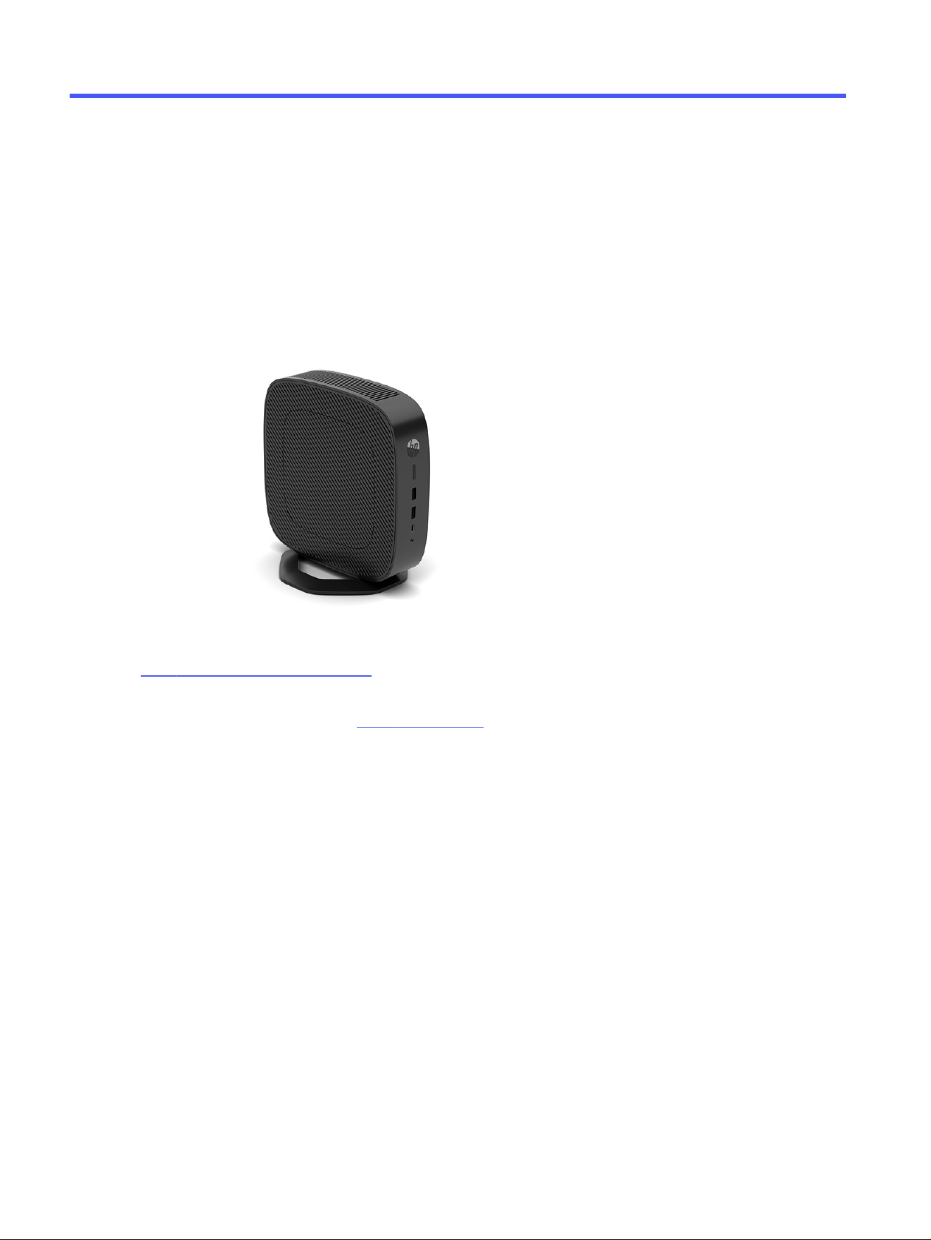
Components
To identify the thin client components, use this illustration and table.
2
Chapter 2 Computer features
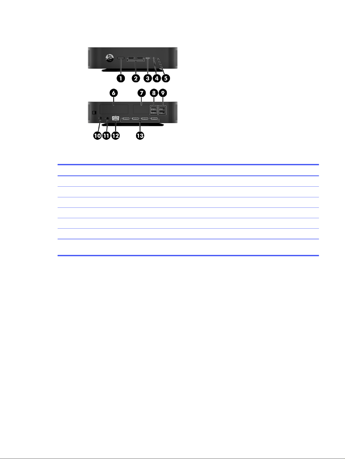
Table 2-1 Identifying the front and rear panel components
Components
1 Power button 8 USB 5 Gbps ports (2)
2 USB 5 Gbps ports (2) 9 USB ports (2)
3 USB Type-C® 10 Gbps port 10 Security cable slot
4 Audio-out (headphone) 11 Power connector
5 Activity LED 12 RJ-45 (network) jack
6 PCIe option panel 13 DisplayPort™ connectors (4)
7 Optional port. If used, supports the following: single
serial port, antennae, or audio headset
Labels
The labels affixed to the computer provide information you might need when you troubleshoot system
problems or travel internationally with the computer. Labels might be in paper form or imprinted on
bottom of the product.
● Service label—Provides important information to identify your computer. When contacting support,
you might be asked for the serial number, the product number, or the model number. Locate this
information before you contact support.
Labels
3
Table 2-2 Service label components
Component Description
1 Regulatory model number
2 HP product name
3 Warranty period
4 Serial number
5 Product number
6 LAN MAC
● Regulatory labels—Provide regulatory information about the computer.
● Wireless certification labels—Provide information about optional wireless devices and the approval
markings for the countries or regions in which the devices have been approved for use.
Setup
Follow the instructions carefully to set up your thin client.
Warnings and cautions
Before performing upgrades, be sure to carefully read all of the applicable instructions, cautions, and
warnings in this guide.
WARNING! To reduce the risk of personal injury or equipment damage from electric shock, hot
surfaces, or fire:
● Install the thin client in a location where children are unlikely to be present.
● Disconnect power from the thin client and allow the internal system components to cool before you
touch them.
● Do not plug telecommunications or telephone connectors into the network interface controller
(NIC) receptacles.
● Do not disable the power cord grounding plug. The grounding plug is an important safety feature.
4
Chapter 2 Computer features
● Plug the power cord into a grounded (earthed) AC outlet that is easily accessible at all times.
To reduce the risk of serious injury, read the Safety & Comfort Guide. It describes proper workstation
setup, posture, and health and work habits for thin client users, and provides important electrical
and mechanical safety information. The Safety & Comfort Guide is located on the HP website at
http://www.hp.com/ergo.
WARNING! Energized parts are inside.
● Disconnect power to the equipment before removing the enclosure.
● Replace and secure the enclosure before re-energizing the equipment.
IMPORTANT: Static electricity can damage the electrical components of the thin client or optional
equipment. Before beginning the following procedures, be sure that you are discharged of static
electricity by briefly touching a grounded metal object. See Electrostatic discharge on page 52 for
more information.
When the thin client is plugged into an AC power source, voltage is always applied to the system board.
To prevent damage to internal components, you must disconnect the power cord from the power
source before opening the thin client.
NOTE: An optional Quick Release mounting bracket is available from HP for mounting the thin client to
a wall, desk, or swing arm. When the mounting bracket is used, do not install the thin client with the I/O
ports oriented towards the ground.
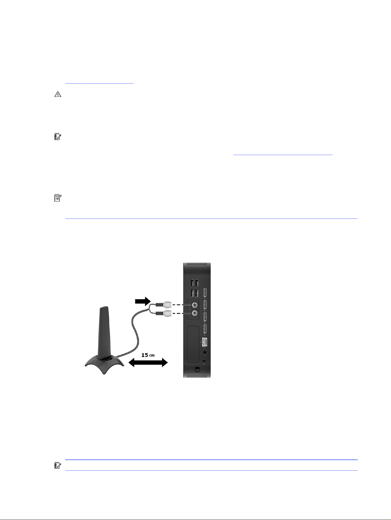
Connecting external Wi-Fi antennas
Read this section to learn how to connect an external Wi-Fi® antenna to your computer.
For best performance, place the antenna on either side of the computer where it has the clearest line of
sight to the access point or router. The recommended distance is more than 15 cm from the computer.
Avoid placing the antenna in front, behind, left, right, or on top of the computer because of the risk of
noise interference.
Mounting and orienting the thin client
You can mount and orient the thin client in several different ways.
IMPORTANT: Use an HP-approved mounting bracket to avoid cracking the thin client.
Connecting external Wi-Fi antennas
5
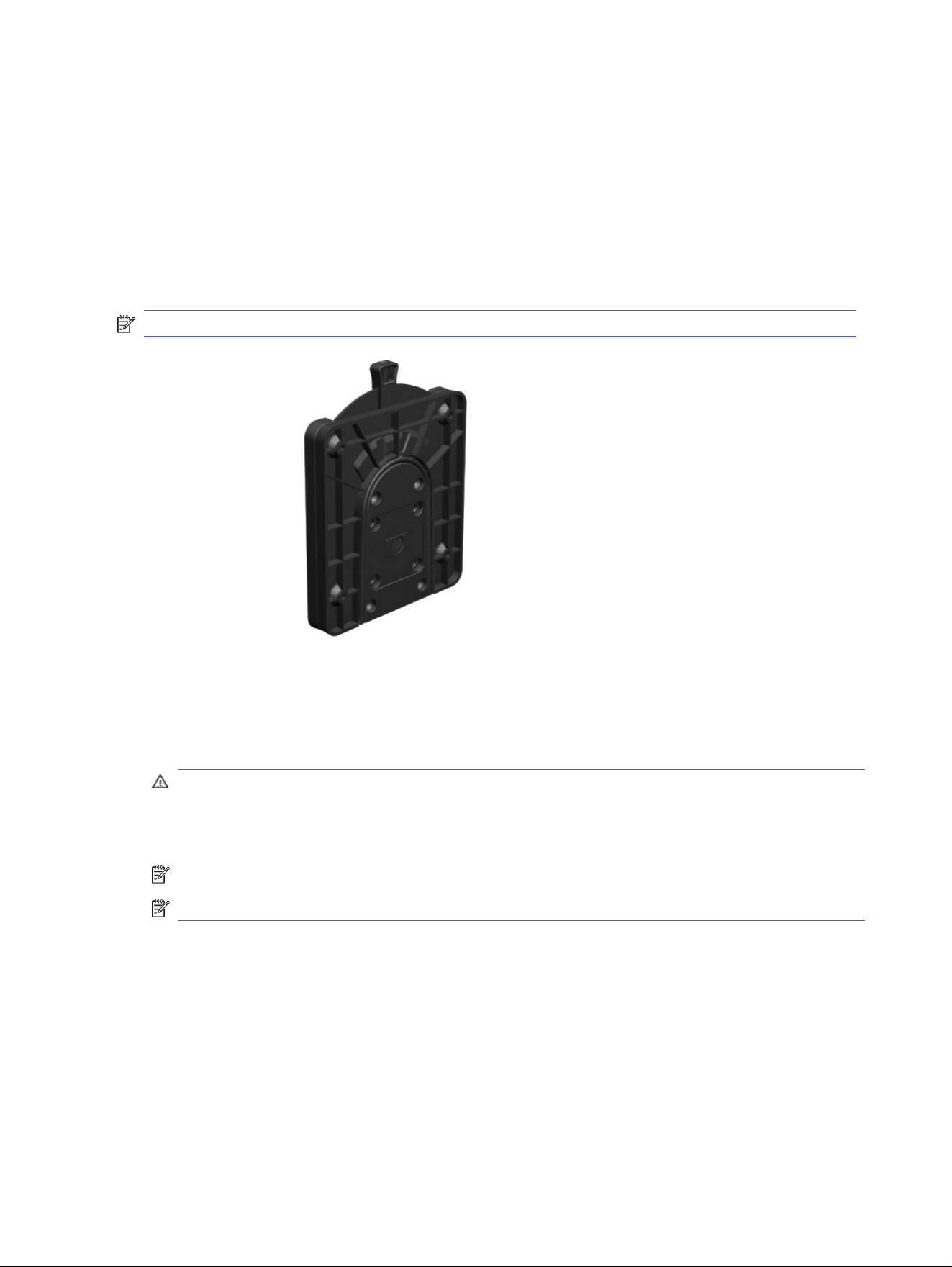
HP Quick Release
An optional Quick Release mounting bracket is available from HP for mounting the thin client to a wall,
desk, or swing arm. When the mounting bracket is used, do not install the thin client with the I/O ports
oriented towards the ground.
This thin client incorporates four mounting points on the right side of the unit. These mounting points
follow the Video Electronics Standards Association (VESA®) standard, which provides industry-standard
mounting interfaces for Flat Displays (FDs), such as flat panel monitors, flat displays, and flat TVs. The
HP Quick Release connects to the VESA-standard mounting points, allowing you to mount the thin client
in a variety of orientations.
NOTE: When mounting to a thin client, use the 10 mm screws supplied with the HP Quick Release.
To use the HP Quick Release:
1. Lay the thin client down with the right side up and the front side with the HP logo facing you.
2. Lift the side cover at the recess (1), and then remove the cover (2) from the thin client. You can use a
thin coin or a flat-bladed screwdriver to remove the cover.
CAUTION: If the thin client has been in operation prior to removing the side cover, the metal plate
underneath the side cover can reach temperatures that may cause discomfort if directly touched.
Turn the thin client off and allow 20 minutes for it to cool down to room temperature before you
remove the side cover.
NOTE: Retain the side cover for possible future use.
NOTE: These images are representative of the thin client. Your product might differ.
6
Chapter 2 Computer features
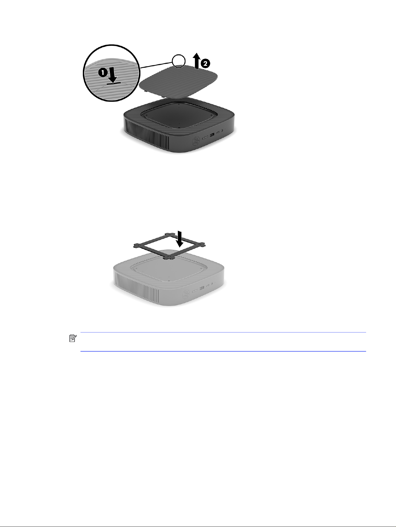
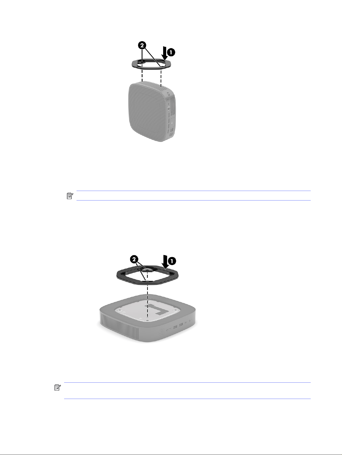
3. Set the thin spacer into the depression on the right side of the thin client.
NOTE: Two spacers are included with the thin client. Use the thinner spacer when mounting the
thin client.
HP Quick Release
7
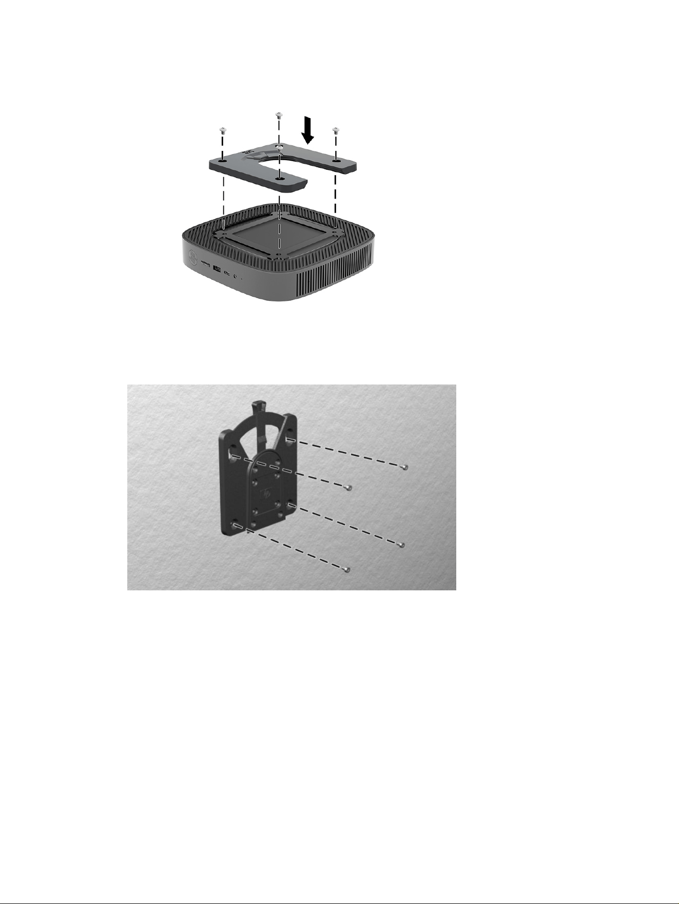
4. Using four 10 mm screws included in the mounting device kit, attach one side of the HP Quick
Release to the thin client as shown in the following illustration.
5. Using four screws included in the mounting device kit, attach the other side of the HP Quick
Release to the device you will mount the thin client to. Be sure that the release lever points upward.
8
Chapter 2 Computer features
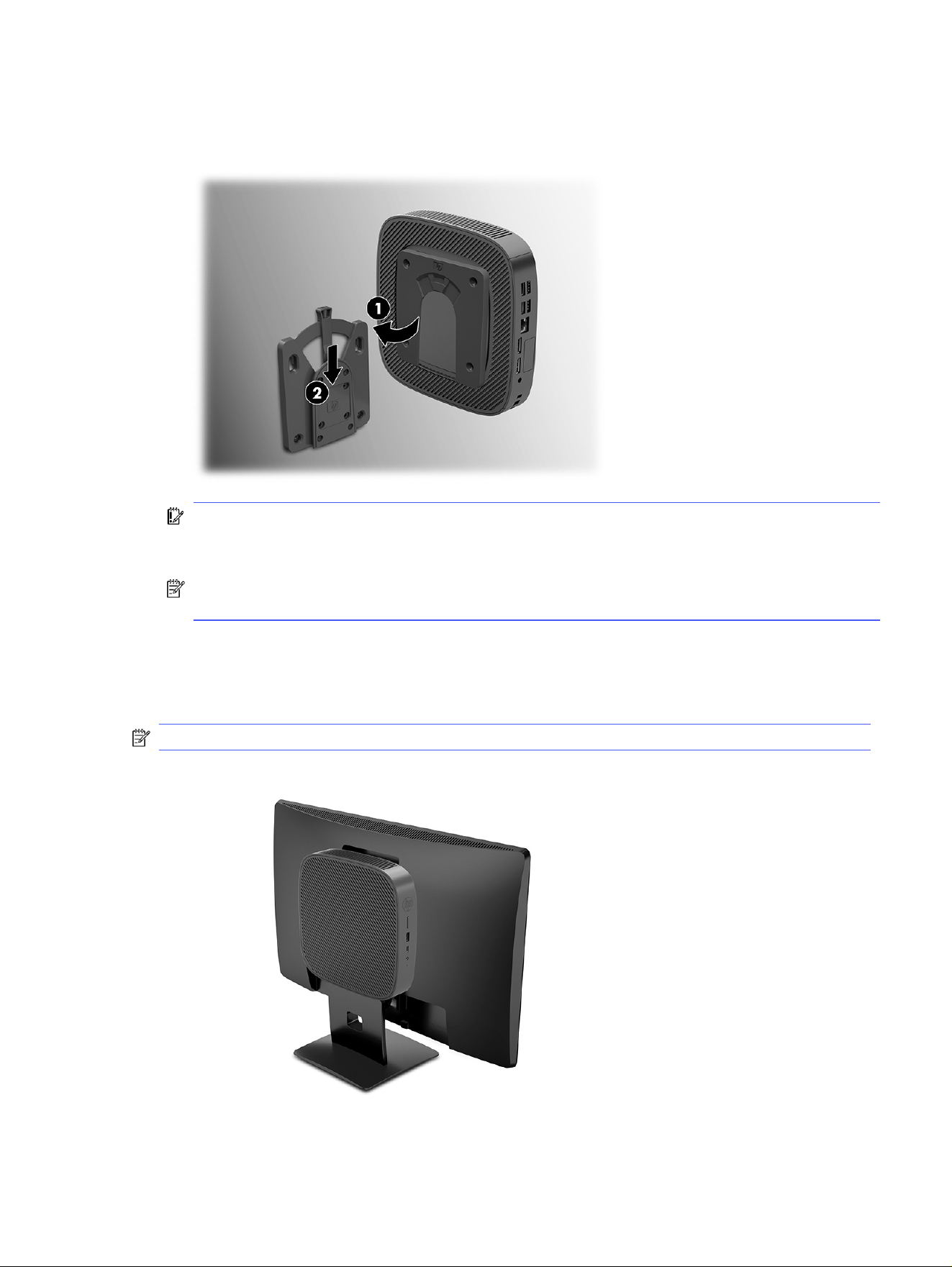
6. Slide the side of the mounting device attached to the thin client (1) over the other side of the
mounting device (2) on the device where you want to mount the thin client. An audible click indicates
a secure connection.
IMPORTANT: To ensure proper function of the HP Quick Release and a secure connection of all
components, be sure that both the release lever on one side of the mounting device and the
rounded opening on the other side face upward.
NOTE: When attached, the HP Quick Release automatically locks in position. You need to slide the
lever only to one side to remove the thin client.
Supported mounting options
The following illustrations demonstrate some of the supported mounting options for the mounting
bracket.
NOTE: These images are representative of the thin client. Your product might differ.
On the back of a monitor:
On a wall:
Supported mounting options
9
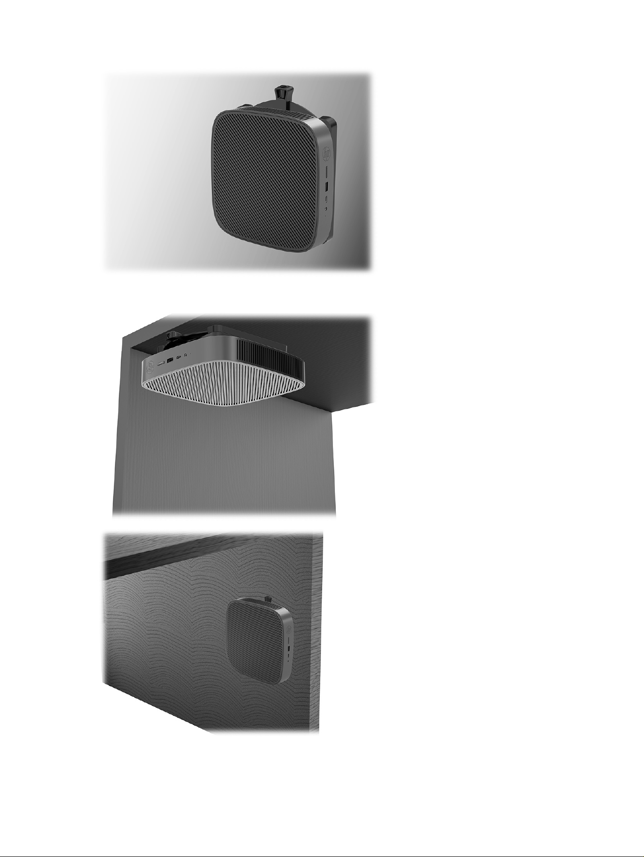
Under a desk:
10
Chapter 2 Computer features
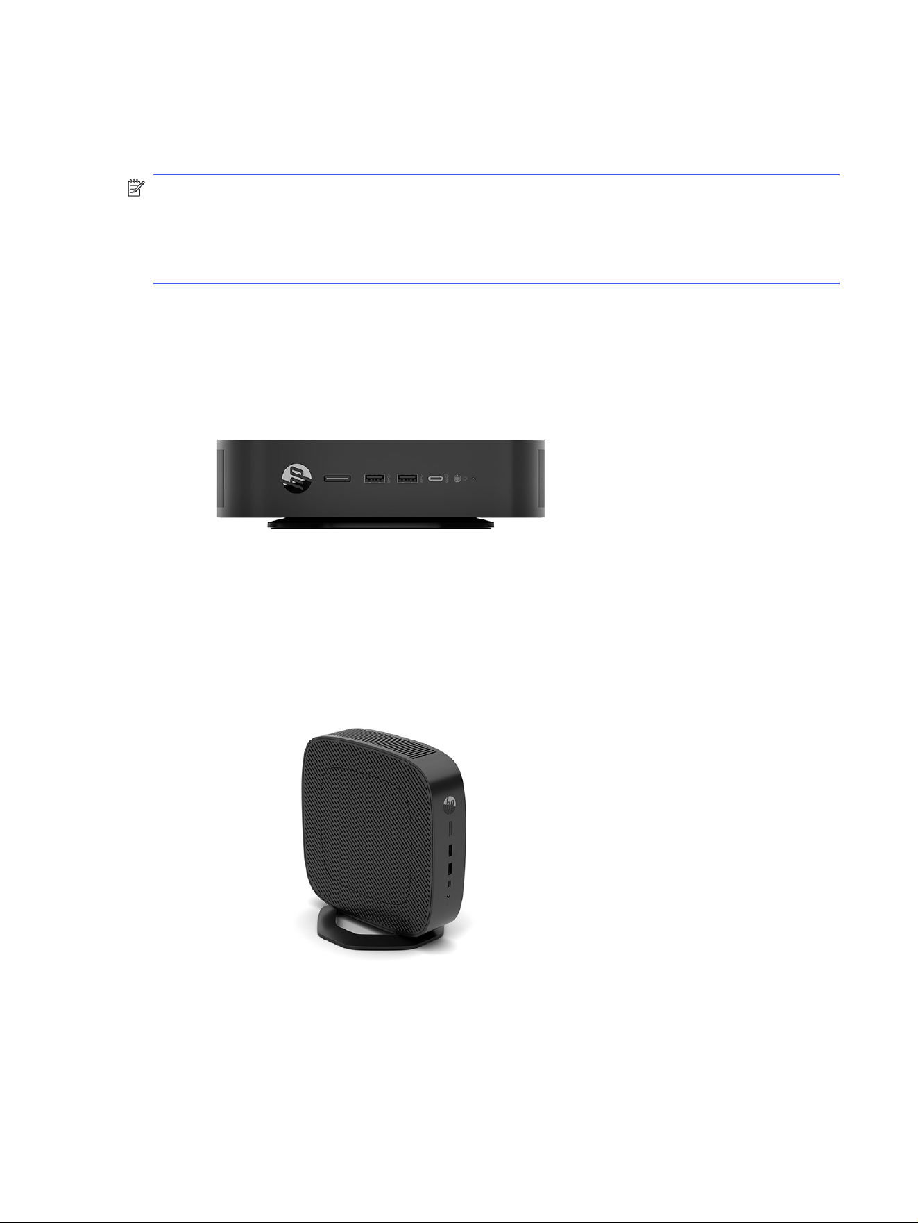
Supported orientation and placement
The following illustrations demonstrate some of the supported orientation and placement options for
the thin client.
NOTE: You must adhere to the HP-supported orientation to ensure your thin clients function properly.
Unless the thin client is mounted with the HP Quick Release, you must operate it with the stand
attached to ensure proper airflow around the thin client.
These images are representative of the thin client. Your product might differ.
● HP supports the horizontal orientation for the thin client:
● HP supports the vertical orientation for the thin client:
● You can place the thin client under a monitor stand with at least 2.54 cm (1 in) clearance:
Supported orientation and placement
11
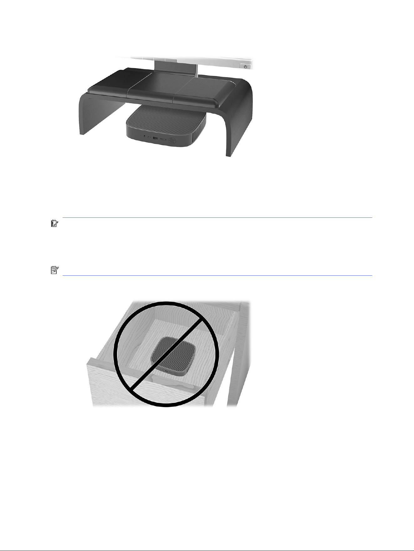
Unsupported placement
HP does not support the following placements for the thin client:
IMPORTANT: Unsupported placement of thin clients could result in operation failure, damage to the
devices, or both.
● Thin clients require proper ventilation to maintain operating temperature. Do not block the vents.
● Do not install the thin client with the I/O ports oriented towards the ground.
NOTE: These images are representative of the thin client. Your product might differ.
● In a desk drawer:
● With a monitor on the thin client:
12
Chapter 2 Computer features

Routine thin client care
Use the following information to properly care for your thin client:
● Never operate the thin client with the outside panel removed.
● Keep the thin client away from excessive moisture, direct sunlight, and extreme heat and cold. For
information about the recommended temperature and humidity ranges for the thin client, go to
http://www.hp.com/go/quickspecs.
● Keep liquids away from the thin client and keyboard.
● Turn off the thin client and wipe the exterior with a soft, damp cloth as needed. Using cleaning
products can discolor or damage the finish.
Installing the stand
You can use the thin client in either a tower or horizontal orientation with the stand included with the thin
client.
IMPORTANT: Unless the thin client is mounted with the HP Quick Release, it must be operated with the
stand attached to ensure proper airflow around the thin client.
1. Turn off the thin client properly through the operating system, and then turn off any external
devices.
2. Disconnect the power cord from the AC outlet and disconnect any other cables or devices such as
USB flash drives from the thin client.
3. Remove or disengage any security devices that prohibit opening the thin client.
4. Tower orientation: Attach the stand to the bottom of the thin client.
a. Turn the thin client upside down and locate the two screw holes in the grid on the bottom of the
thin client.
b. Position the stand (1) over the bottom of the thin client and line up the captive screws in the
stand with the screw holes in the thin client.
c. Tighten the captive screws (2) securely.
Routine thin client care
13
5. Horizontal orientation: Attach the stand to the right side of the thin client.
a. Lay the thin client down with the right side up and the front side with the HP logo facing you.
b. Lift the side cover at the recess, and then remove the cover from the thin client.
NOTE: Retain the side cover for possible future use.
c. Lay the thin client down with the right side up and locate the two screw holes in the grid on the
right side of the thin client.
d. Position the stand (1) over the side of the thin client and then lower it onto the thin client.
e. Line up the captive screws (2) in the stand with the screw holes in the thin client.
f. Tighten the captive screws securely.
6. Reconnect the power cord and any other cables or USB flash devices.
NOTE: Be sure that at least 10.2 cm (4 in) of space on all sides of the thin client remain clear and
free of obstructions.
14
Chapter 2 Computer features
7. Lock any security devices that were disengaged when the thin client cover or access panel was
removed.
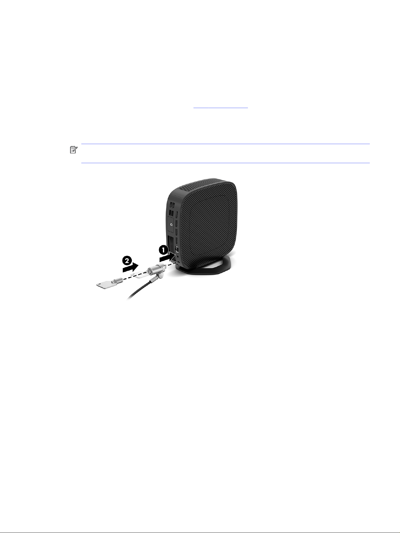
Securing the thin client
Your thin client is designed to accept a security cable. The security cable prevents unauthorized removal
of the thin client and access to the secure compartment.
To order this option, go to the HP website at http://www.hp.com and search for your specific thin client.
1. Locate the security cable slot on the back panel.
2. Insert the security cable lock into the slot (1), and then use the key to lock it (2).
NOTE: The security cable is designed to act as a deterrent, but it might not prevent the computer
from being mishandled or stolen.
Connecting the power cord
Connect a power cord to your computer by following these steps.
1. Connect the power cord to the power adapter (1).
2. Connect the power cord to an AC outlet (2).
Securing the thin client
15
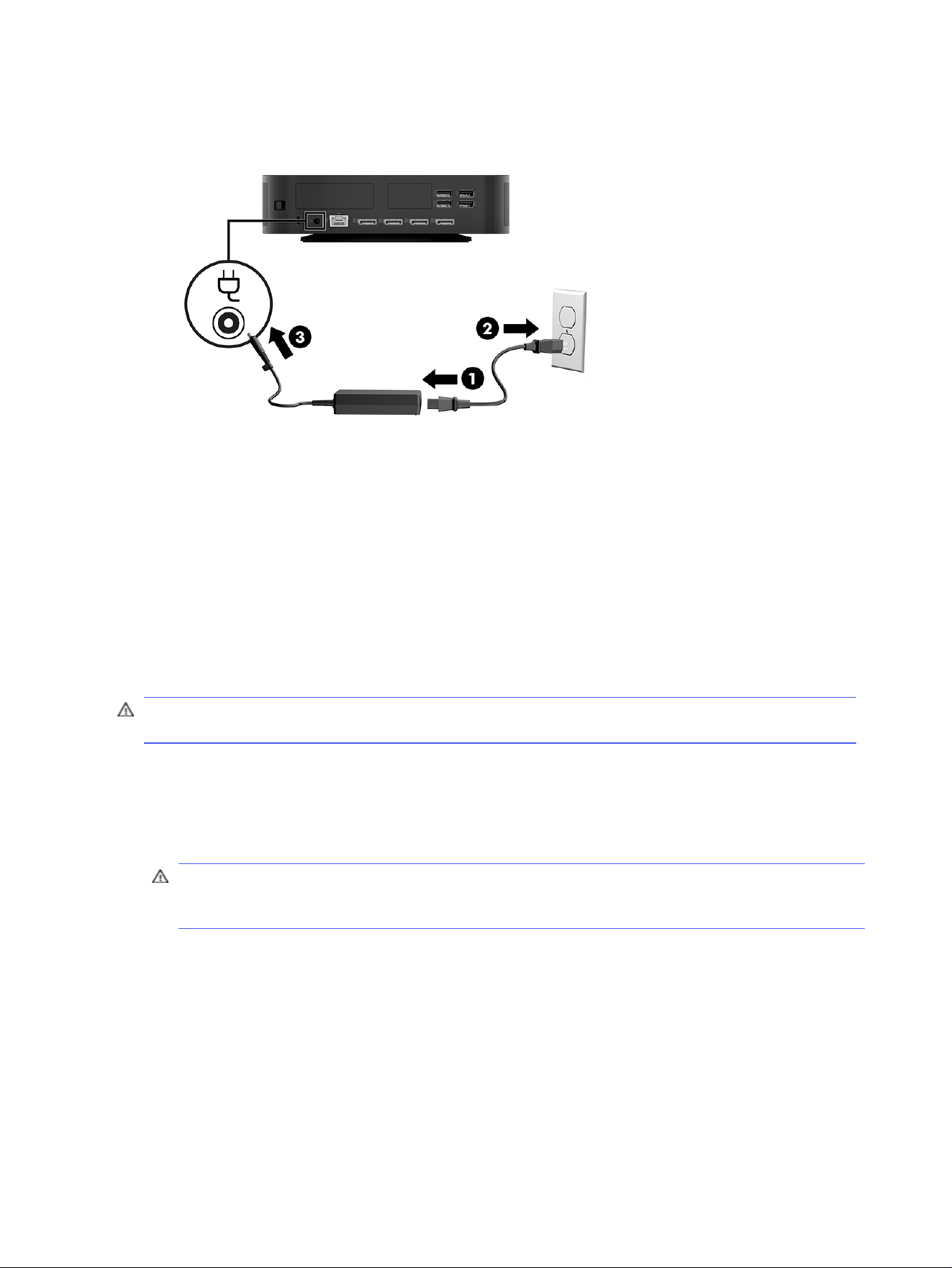
3. Connect the power cord to the thin client (3).
Hardware changes
You can change or replace certain thin client hardware.
Removing and replacing the access panel
Remove the access panel to replace or upgrade internal components.
Removing the access panel
To remove the access panel, use these procedures.
WARNING! Before removing the access panel, be sure that the thin client is turned off and the power
cord is disconnected from the AC outlet.
1. Turn off the thin client properly through the operating system, and then turn off any external
devices.
2. Disconnect the power cord from the AC outlet and disconnect any other cables or devices such as
USB flash drives from the thin client.
CAUTION: Regardless of the power-on state, voltage is always present on the system board as
long as the system is plugged into an active AC outlet. You must disconnect the power cord to avoid
damage to the internal components of the thin client.
3. Remove or disengage any security devices that prohibit opening the thin client.
4. Remove the stand from the thin client.
a. Turn the thin client upside down and locate the two screw holes in the grid on the bottom of the
thin client.
b. Loosen the captive screws to release the stand (1) and pull the stand off the thin client (2).
Tower orientation
16
Chapter 2 Computer features
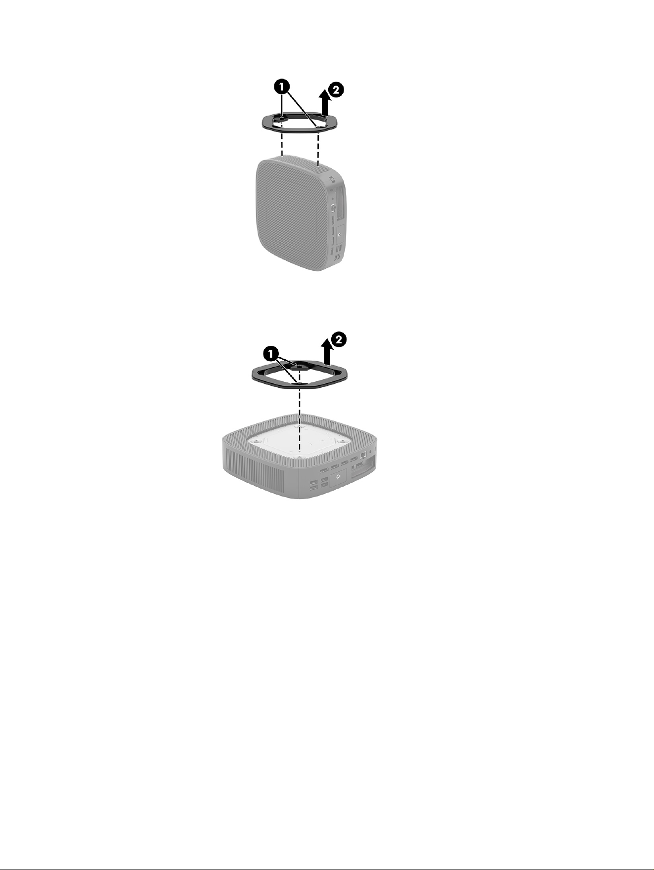
Horizontal orientation
5. Lay the unit flat on a stable surface with the left side up.
Removing the access panel
17
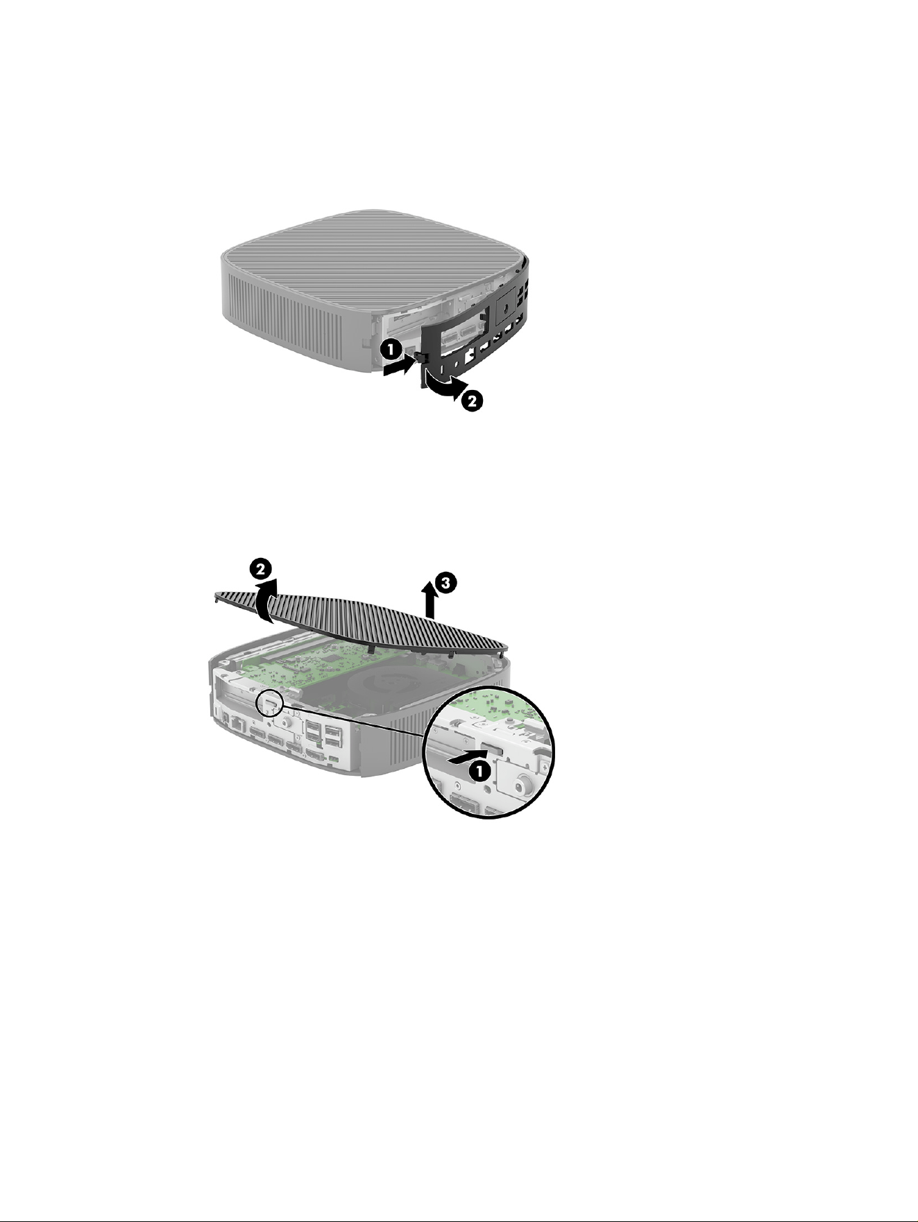
6. Release the latch (1) on the right side of the rear I/O panel, rotate the I/O panel (2) to the left, and
then lift it off the thin client.
7. Press the latch (1) that secures the access panel to the chassis.
8. Rotate the access panel upward (2) and lift it off the thin client (3).
Replacing the access panel
To replace the access panel, use these procedures.
18
Chapter 2 Computer features
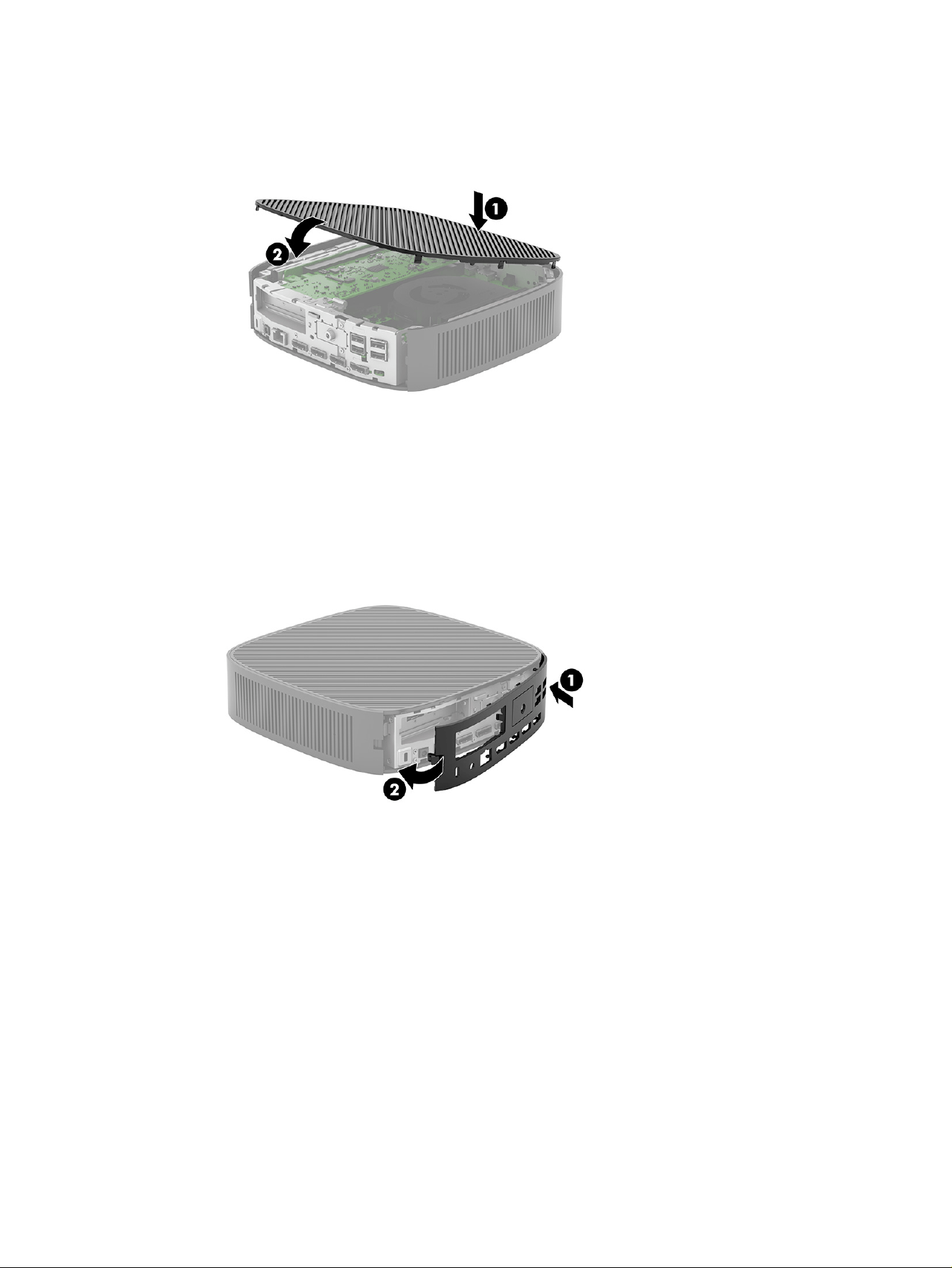
1. Insert the access panel (1), and then rotate the access panel down into place to secure the latch (2).
2. Insert the hooks on the left side of the rear I/O panel (1) into the left side of the back of the chassis,
rotate the right side (2) to the chassis, and then press the right side into the chassis until it locks in
place.
3. Replace the thin client stand.
4. Reconnect the power cord and turn on the thin client.
5. Lock any security devices that were disengaged when the thin client access panel was removed.
Locating internal components
Use this illustration and table to identify thin client internal components.
Locating internal components
19
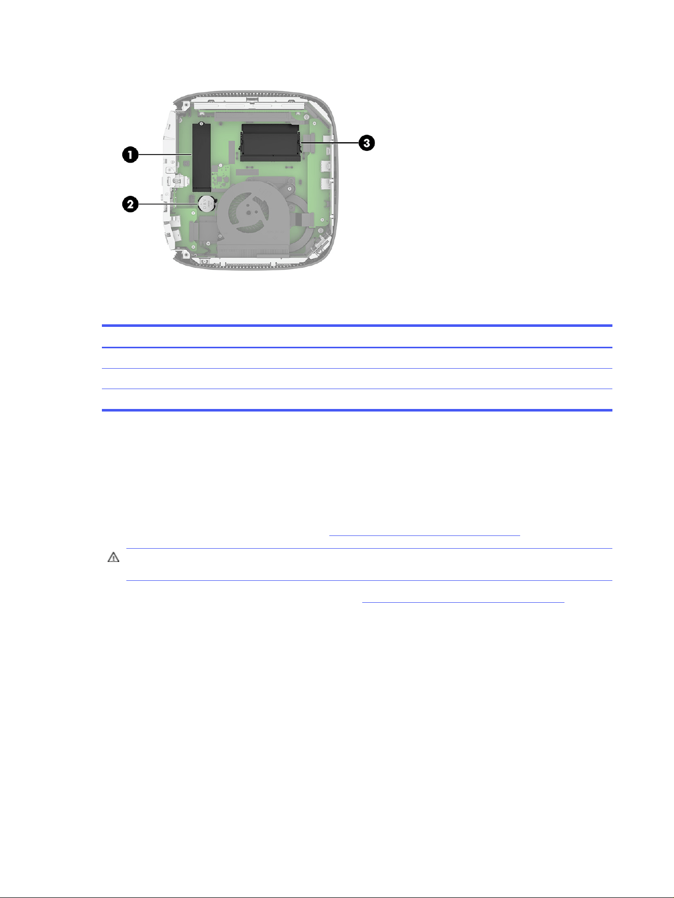
Table 2-3 Identifying the internal components
Item Component
1 M.2 socket for a 30 mm (2230) or 80 mm (2280) M.2 storage module (2)
2 Battery
3 System memory module
Replacing the M.2 storage module
You can install a 30 mm (2230) or an 80 mm (2280) M.2 storage module in the thin client. To replace the
M.2 storage module, use these procedures.
To replace the M.2 storage module:
1. Remove the thin client access panel. See Removing the access panel on page 16.
WARNING! To reduce risk of personal injury from hot surfaces, allow the internal system
components to cool before you touch them.
2. Locate the M.2 socket on the system board. See Locating internal components on page 19.
3. Loosen the screw securing the storage module until the end of the module can be raised.
20
Chapter 2 Computer features
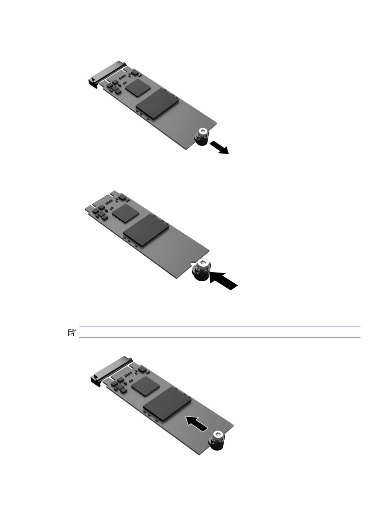
4. Pull the storage module out of the socket.
5. Pull the screw kit off the storage module and attach it to the replacement storage module.
6. Slide the new storage module into the M.2 socket on the system board and press the module
connectors firmly into the socket.
NOTE: A storage module can be installed in only one way.
Replacing the M.2 storage module
21
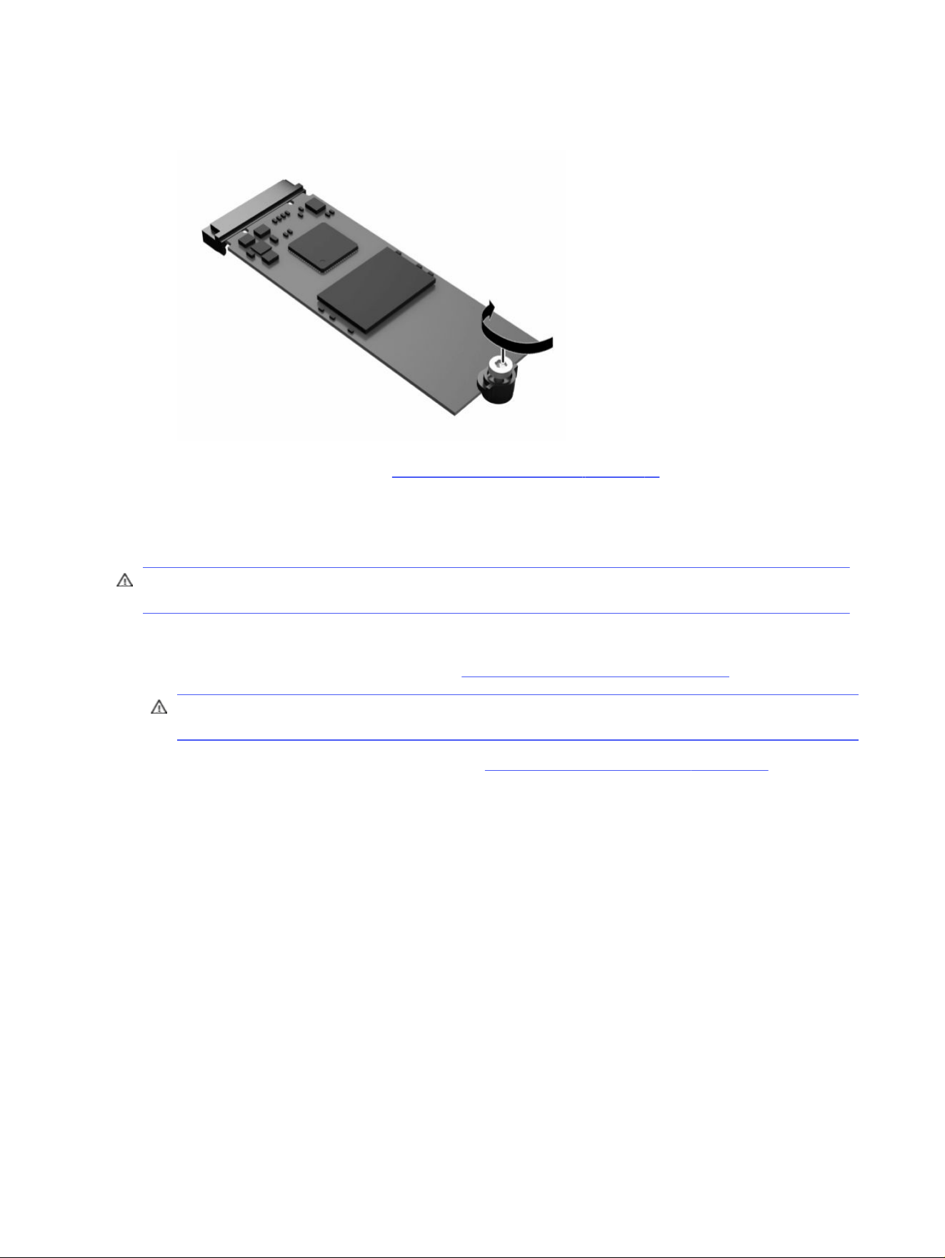
7. Press the storage module down and use a screwdriver to tighten the screw and secure the module
to the system board.
8. Replace the access panel. See Replacing the access panel on page 18.
Removing and replacing the battery
To remove and replace the battery, use these procedures.
WARNING! Before removing the access panel, be sure that the thin client is turned off and the power
cord is disconnected from the AC outlet.
To remove and replace the battery:
1. Remove the thin client access panel. See Removing the access panel on page 16.
WARNING! To reduce risk of personal injury from hot surfaces, allow the internal system
components to cool before you touch them.
2. Locate the battery on the system board. See Locating internal components on page 19.
3. To release the battery from its holder, squeeze the metal clamp that extends above one edge of the
battery. When the battery pops up, lift it out (1).
22
Chapter 2 Computer features
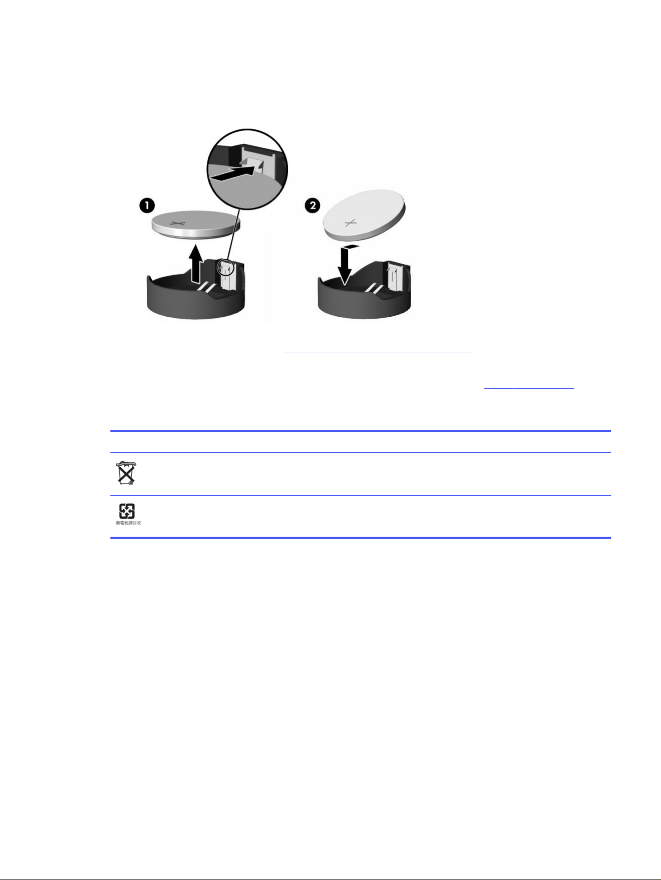
4. To insert the new battery, slide one edge of the replacement battery under the holder’s lip with the
positive side up. Push the other edge down until the clamp snaps over the other edge of the battery
(2).
5. Replace the access panel. See Replacing the access panel on page 18.
HP encourages customers to recycle used electronic hardware, HP original print cartridges, and
rechargeable batteries. For more information about recycling programs, go to http://www.hp.com and
search for “recycle.”
Table 2-4
Battery icon definitions
Icon Definition
Do not dispose of batteries, battery packs, and accumulators with the general household waste. In
order to forward them to recycling or proper disposal, use the public collection system or return them
to HP, an authorized HP partner, or their agents.
The Taiwan EPA requires dry battery manufacturing or importing firms, in accordance with Article 15
or the Waste Disposal Act, to indicate the recovery marks on the batteries used in sales, giveaways,
or promotions. Contact a qualified Taiwanese recycler for proper battery disposal.
Upgrading system memory
The memory socket on the system board is populated with two memory modules. To achieve the
maximum memory support, you can populate the memory sockets with up to 32 GB of memory.
For proper system operation, the memory module must adhere to the following specifications:
● Industry-standard 260-pin Small Outline DIMM (SODIMM)
● Unbuffered non-ECC PC4-25600 DDR4-3200 MT/s
● 1.2 volt DDR4-SDRAM memory module
The thin client supports the following:
● Single-rank and dual-rank modules
● Single-sided and double-sided memory modules
Upgrading system memory
23

A higher-speed DDR4 SODIMM module operates at a maximum system memory speed of 3200 MT/s.
NOTE: The system does not operate properly when an unsupported memory module is installed.
Single vs. dual DIMM modules
Your thin client may come with one or two DIMM modules installed. Using two modules provides
the highest possible system performance, because both modules can be accessed simultaneously,
potentially doubling memory throughput.
For example, the system performs better with two 4 GB DIMM modules than with one 8 GB module, even
though the total memory capacity is the same. Both modules must be exactly the same type and have
the same performance, so if you add a second DIMM, be sure that the specifications are identical to the
original module. For reliable operation, HP recommends that you use matching modules from the same
manufacturer and part number.
If you choose to install a single DIMM module, be sure that you install it in the lower slot (closest to the
main system board).
Installing a memory module
To install a memory module, use these procedures.
IMPORTANT: You must unplug the power cord and wait approximately 30 seconds for the power to
drain before adding or removing the memory module. Regardless of the power-on state, voltage is
always supplied to the memory module as long as the thin client is plugged into an active AC outlet.
Adding or removing the memory module while voltage is present can cause irreparable damage to the
memory module or system board.
The memory module socket has gold-plated metal contacts. When upgrading the memory, it is
important to use a memory module with gold-plated metal contacts to prevent corrosion or oxidation
resulting from having incompatible metals in contact with each other.
Static electricity can damage the electronic components of the thin client. Before beginning the
following procedures, be sure that you are discharged of static electricity by briefly touching a
grounded metal object. For more information, see Electrostatic discharge on page 52.
When handling a memory module, be careful not to touch any of the contacts. Doing so can damage
the module.
To install a memory module:
1. Remove the thin client access panel. See Removing the access panel on page 16.
WARNING! To reduce risk of personal injury from hot surfaces, allow the internal system
components to cool before you touch them.
2. Locate the memory module on the system board. See Locating internal components on page 19.
24
Chapter 2 Computer features
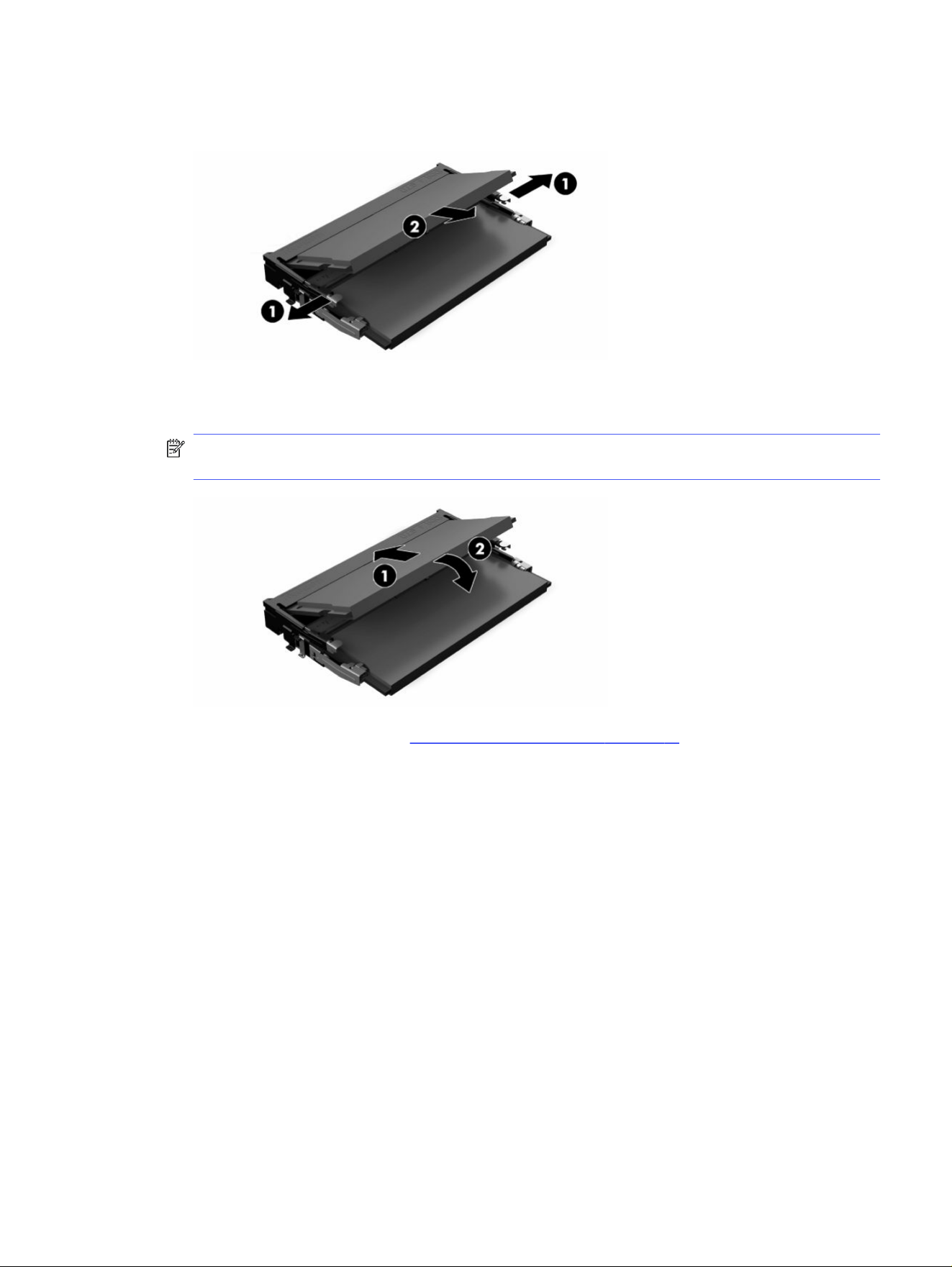
3. To remove the memory module, press outward on the latches on each side of the memory module
(1), rotate the memory module up, and then pull the memory module out of the socket (2).
4. Slide the new memory module (1) into the socket at approximately a 30° angle, and then press the
memory module down (2) so that the latches lock it in place.
NOTE: A memory module can be installed in only one way. Match the notch on the module with the
tab on the memory socket.
5. Replace the access panel. See Replacing the access panel on page 18.
The thin client automatically recognizes the new memory when you turn on the thin client.
Installing a memory module
25

Troubleshooting3
This chapter provides you with information to help with troubleshooting your thin client.
Computer Setup (F10) Utilities
This information provides details of the Computer Setup Utility.
Use Computer Setup (F10) Utility to do the following tasks:
● Change settings from the defaults or restore the settings to default values.
● Set the system date and time.
● Set, view, change, or verify the system configuration, including settings for processor, graphics,
memory, audio, storage, communications, and input devices.
● Modify the boot order of bootable devices such as solid-state drives or USB flash media devices.
● Select POST Messages Enabled or Disabled to change the display status of Power-On Self-Test
(POST) messages. POST Messages Disabled suppresses most POST messages, such as memory
count, product name, and other non-error text messages. If a POST error occurs, the error is
displayed regardless of the mode selected. To manually switch to POST Messages Enabled during
POST, press any key except f1 through f12.
● Enter the Asset Tag or property identification number assigned by the company to this computer.
● Enable the power-on password prompt during system restarts (warm boots) as well as during
startup.
● Establish a setup password that controls access to the Computer Setup (F10) Utility and the settings
described in this section.
● Secure integrated I/O functionality, including the USB, audio, or embedded NIC, so that they cannot
be used until they are unsecured.
Using Computer Setup (F10) Utilities
You can access Computer Setup only by turning the computer on or restarting the system.
To access the Computer Setup Utilities menu, complete these steps:
1. Turn on or restart the computer.
2. Press either esc or f10 while the “Press the ESC key for Startup Menu” message is displayed at the
bottom of the screen.
Pressing esc displays a menu that allows you to access different options available at startup.
NOTE: If you do not press esc or f10 at the appropriate time, you must restart the computer and
again repeatedly press esc or f10 when the power button light turns white to access the utility.
26
Chapter 3 Troubleshooting

NOTE: You can select the language for most menus, settings, and messages using the Language
Selection option using the f8 key in Computer Setup.
3. If you pressed esc, press f10 to enter Computer Setup.
A choice of five headings appears in the Computer Setup Utilities menu: File, Storage, Security,
Power, and Advanced.
4. Use the arrow (left and right) keys to select the appropriate heading. Use the arrow (up and down)
keys to select the option that you want, and then press enter. To return to the Computer Setup
Utilities menu, press esc.
5. To apply and save changes, select File, and then select Save Changes and Exit.
● If you have made changes that you do not want applied, select Ignore Changes and Exit.
● To reset to factory settings, select Apply Defaults and Exit. This option restores the original
factory system defaults.
IMPORTANT: Do not turn the computer power off while the BIOS is saving the Computer Setup
(F10) changes because the CMOS could become corrupted. It is safe to turn off the computer only
after exiting the F10 Setup screen.
Computer Setup—File
This table provides information about the Computer Setup File menu.
NOTE: Support for specific Computer Setup options can vary, depending on the hardware
configuration.
Computer Setup—File
27

Table 3-1 Computer Setup—File
Option Description
System Information Lists:
● Product name
● System board CT number
● Processor type
● Processor speed
● Processor stepping
● Cache size (L1/L2/L3)
● Memory size
● Integrated MAC
● System BIOS
● USB Type-C PD FW Version
● TPM Firmware Version
● Chassis serial number
● SKU Number
● UUID
● Asset tracking number
● Feature Byte
● Build ID
About
Displays copyright notice.
Flash System BIOS Allows you to flash system BIOS or device firmware from a USB recovery key.
Set Time and Date Allows you to set system time and date.
Default Setup Allows you to:
● Save Current Settings as Default
● Restore Factory Settings as Default
Apply Defaults and Exit Applies the original factory system configuration settings for use by a subsequent Apply Defaults
and Exit action.
Ignore Changes and Exit Exits Computer Setup without applying or saving any changes.
Save Changes and Exit Saves changes to current system configuration, exits Computer Setup, and reboots.
Computer Setup—Storage
This table provides information about the Computer Setup Storage menu.
NOTE: Support for specific Computer Setup options can vary, depending on the hardware
configuration.
28
Chapter 3 Troubleshooting

Table 3-2 Computer Setup—Storage
Option Description
Device configuration Lists all installed BIOS-controlled storage devices. When a device is selected, detailed information
and options are displayed. The following options can be presented:
● Hard Disk—Size, model, firmware version, serial number.
● Secure Erase—Allows you to use the software utility to issue a Secure Erase instruction to a
target storage device during the next boot.
Storage Options External USB Storage Boot—Allows you to set USB storage device.
Boot Order Allows you to:
● Specify the order for checking EFI boot sources (such as a internal drive, USB hard drive,
or USB optical drive) for a bootable operating system image. Each device on the list can be
individually excluded from or included for consideration as a bootable operating system source.
● Specify the order of attached hard drives. The first hard drive in the order has priority in the
boot sequence and is recognized as drive C (if any devices are attached).
NOTE: You can use f5 to disable individual boot items, as well as disable EFI boot.
Shortcut to Temporarily Override Boot Order
To boot one time from a device other than the default device specified in Boot Order:
1. Restart the computer.
2. Complete one of these tasks:
a. Press esc (to access the
Startup
menu) and then f9 (Boot Menu).
b. Press f9 (skipping the Startup menu) when the power button light turns white. After POST
is completed, a list of bootable devices is displayed.
3. Use the arrow keys to select the preferred bootable device and press enter. The computer then
boots from the selected device for this one time.
Computer Setup—Security
This table provides information about the Computer Setup Security menu.
NOTE: Support for specific Computer Setup options can vary, depending on the hardware
configuration.
Table 3-3
Computer Setup—Security
Option Description
Setup Password Allows you to set and enable a setup (administrator) password.
NOTE: If the setup password is set, you must supply the password to change Computer Setup
options, flash the ROM, and make changes to certain plug and play settings under Windows®.
Power-On Password Allows you to set and enable a power-on password. The power-on password prompt appears after a
power cycle or reboot. If you do not enter the correct power-on password, the unit will not boot.
Computer Setup—Security 29

Table 3-3 Computer Setup—Security (continued)
Option Description
Password Options
(This selection shows
only if a power-on
password or setup
password is set.)
Allows you to enable or disable:
● Stringent Password—When set, enables a mode that does not permit physical bypass of the
password function. If strong password is enabled, you cannot remove the password jumper on
the system board. You must enter the Setup password.
● Password Prompt on F9 & F12—Default is enabled.
● Setup Browse Mode—Allows viewing, but not changing, the F10 Setup Options without entering
the setup password. Default is enabled.
Device Security Allows you to set Device Available (default) or Device Hidden for:
● System audio
● Network controller
● M.2 Storage 0
USB Security Allows you to set Enabled (default) or Disabled for:
● Front USB ports
● Rear USB ports
Slot Security Allows you to disable the M.2 PCI Express slot. Default is enabled.
● Slot #—M.2 PCIe x1
IMPORTANT: Choosing to disable the PCIe slot will disable the on-board storage module. You will no
longer be able to boot the thin client unless you connect an external storage device instead.
Memory Security Allows you to enable or disable AMD® MemoryGuard, also known as Transparent Secure Memory
Encryption. Default is Enabled. For maximum security, HP recommends you leave this setting as
Enabled.
Network Boot Enables/disables the computer’s ability to start from an operating system installed on a network
server. (Feature is available on NIC models only; the network controller must be either a PCI
expansion card or embedded on the system board.) Default is enabled.
System IDs Allows you to set:
● Asset tag (18-byte identifier)—A property identification number assigned by the company to the
computer
● Ownership tag (80-byte identifier)
30 Chapter 3 Troubleshooting

Table 3-3 Computer Setup—Security (continued)
Option Description
System Security Provides these options:
● Data Execution Prevention (enable or disable)—Helps prevent operating system security
breaches. Default is enabled.
● Virtualization Technology (enable or disable)—Controls the virtualization features of the
processor. Changing this setting requires turning the computer off and then back on. Default is
disabled.
● TPM Device—Lets you set the Trusted Platform Module (TPM) as available or hidden.
● TPM State—Select to enable the TPM.
● Clear TPM—Select to reset the TPM to an unowned state. After the TPM is cleared, it is also
turned off. To temporarily suspend TPM operations, turn the TPM off instead of clearing it.
IMPORTANT: Clearing the TPM or disabling it could prevent the thin client from operating. If
you have ThinPro installed with disk encryption turned on, clearing the TPM might make all
programs and data on the storage device permanently unreadable. You would have to then
erase and reload the system software to restore operation.
Secure Boot
Configuration
The options on this setup page are only for Windows 10 and ThinPro 8.0 and above, and other
operating systems that support Secure Boot. Changing the default setting of the setup options
on this page for operating system that do not support Secure Boot can prevent the system from
starting successfully.
Secure Boot (enable or disable)—This item is for Secure Boot flow control. Secure Boot is possible
only if the system runs in user mode.
Key Management
● Clear Secure Boot Keys (Clear or Don’t Clear)—Lets you clear the Secure Boot Key.
● Key ownership (HP keys or Customer keys)—Lets you change the keys of different owners.
Fast Boot (Enable or Disable)—Enabling Fast Boot causes the system to boot by initializing a minimal
set of devices, which is required to launch the Active Boot option. This option has no effect for BIOS
Boot Specification (BBS) boot options.
Computer Setup—Power
This table provides information about the Computer Setup Power menu.
NOTE: Support for specific Computer Setup options can vary, depending on the hardware
configuration.
Table 3-4
Computer Setup—Power
Option Description
OS Power Management Runtime Power Management (enable or disable)—Allows certain operating systems to reduce
processor voltage and frequency when the current software load does not require the full
capabilities of the processor. Default is enabled.
Idle Power Savings (Extended or Normal)—Allows certain operating systems to decrease the
processor's power consumption when the processor is idle. Default is extended.
Hardware Power
Management
S5 Maximum Power Savings—Turns off power to all nonessential hardware when the system is off to
meet the EUP Lot 6 requirement of less than 0.5 Watt power usage. Default is disabled.
Computer Setup—Power 31

Computer Setup—Advanced
This table provides information about the Computer Setup Advanced menu.
NOTE: Support for specific Computer Setup options can vary, depending on the hardware
configuration.
Table 3-5 Computer Setup—Advanced
Option Heading
Power-On Options Allows you to set:
● POST messages (enable or disable). Default is disabled.
● Press the esc key for Startup Menu (Displayed or Hidden).
● After Power Loss (off, on, or previous state). Default is Power off. Set this option as follows:
– Power off causes the computer to remain off when power is restored.
– Power on causes the computer to turn on automatically as soon as power is restored.
– Previous state causes the computer to turn on automatically as soon as power is
restored, if it was on when power was lost.
NOTE: If you turn off power to the computer using the switch on a power strip, you cannot use the
suspend/sleep feature or the Remote Management features.
● POST Delay (in seconds)—Enabling this feature adds a user-specified delay to the POST
process. This delay is sometimes needed for hard disks on some PCI cards that spin up so
slowly that they are not ready to boot by the time POST is finished. The POST delay also gives
you more time to select f10 to enter Computer (F10) Setup. Default is None.
● Bypass f1 Prompt on Configuration Changes (enable or disable).
● Remote Wakeup Boot Source (Local Hard Drive or Remote Server). Allows you to set the source
the computer gets its boot files from when it is remotely awakened.
BIOS Power-On Allows you to set the computer to turn on automatically at a time you specify.
Onboard Devices Allows you to set resources for or disable devices.
Bus Options On some models, you can enable or disable:
● PCI SERR# Generation. Default is enabled.
● PCI VGA Palette Snooping, which sets the VGA palette snooping bit in PCI configuration space.
It is needed only when more than one graphics controller is installed. Default is disabled.
32 Chapter 3 Troubleshooting

Table 3-5 Computer Setup—Advanced (continued)
Option Heading
Device Options ● Integrated Graphics (Auto or Force)—Use this option to manage how much memory is reserved
for video and graphics. Default is Auto, which sets aside 2 GB. If you select Force, the UMA
Frame Buffer Size option opens, which lets you set the UMA memory size allocation between
256 MB and 2 GB. The value you choose allocates memory permanently to graphics, and is
unavailable to the operating system. Unless you are certain you require less graphics memory,
HP recommends leaving this setting at Auto.
– 4 GB: 512 MB
– ≥ 8 GB: 2 GB
If you select Force, the UMA Frame Buffer Size option opens, which lets you set the UMA
memory size allocation between 256 MB and 2 GB.
NOTE: 8 GB RAM is the minimum for Windows on this model, but 4 GB is supported with
ThinPro (or IGEL or No OS.)
● S5 Wake on LAN (enable or disable) - Default is enabled. HP recommends leaving this option
enabled so that remote management solutions (for example, HPDM) can wake up the system to
perform administrative functions.
● Prompt for Power-On Password on Wake-On LAN.
● Num Lock State at Power-On (off or on). Default is off.
● Internal Speaker (select products only) (does not affect external speakers). Default is enabled.
● High-Resolution mode: When you connect to a USB Type-C dock (for example, the HP USB-C®
Dock G5) on an Alt mode dock, you can enable the High-Resolution mode in the BIOS to allow
the dock to support higher resolution monitors.
NOTE: For details about supported resolutions with and without High Resolution mode, go to
http://www.hp.com/go/quickspecs/ and search for HP Dock QuickSpecs.
Option ROM Launch
Policy
Allows you to set Onboard NIC PXE Option ROMs (UEFI or Do not launch).
Electronic Labels This device complies with part 15 of the FCC Rules. Operation is subject to the following conditions:
● The device must not cause harmful interference.
● The device must accept any interference received, including interference that might cause
undesired operation.
Changing BIOS Settings from the HP BIOS Configuration Utility
(HPBCU)
You can change some BIOS settings locally within the operating system without having to go through
the f10 utility. This table identifies the items that you can control with this method.
Table 3-6
BIOS settings
BIOS setting Default value Other values
Language English Francais, Espanol, Deutsch, Italiano, Dansk, Suomi,
Nederlands, Norsk, Portugues, Svenska, Japanese,
Simplified Chinese
Set time 00:00 00:00:23:59
Changing BIOS Settings from the HP BIOS Configuration Utility (HPBCU) 33

Table 3-6 BIOS settings (continued)
BIOS setting Default value Other values
Set Day 01/01/2011 01/01/2011 to current date
Default Setup None Save Current Settings as Default; Restore Factory
Settings as Default
Apply Defaults and
Exit
Disable Enable
USB Storage Boot Before internal storage After internal storage
Secure Erase Disable Enable
UEFI Boot Sources Windows Boot Manager USB Floppy/CD; USB hard drive
System Audio Device available Device hidden
Network Controller Device available Device hidden
M.2 Storage 0 Device available Device hidden
Front USB Ports Enable Disable
USB Port 1, 2 Enable Disable
Rear USB Ports Enable Disable
USB Port 3, 4, 5, 6 Enable Disable
M.2 PCIe x Enable Disable
Network Boot Enable Disable
Asset Tracking
Number
Ownership Tag
BIOS Update Disable Auto; Force
BIOS Image File
Name
Data Execution
Prevention
Enable Disable
Virtualization
Technology
Disable Enable
TPM Device Disable Enable
TPM State Enable Disable
Clear TPM Do not reset Reset
Secure Boot Disable Enable
NOTE: The default value may be varied; depends on the
OS.
Clear Secure Boot
Keys
Don’t Clear Clear
Key Ownership HP Keys Custom Keys
34 Chapter 3 Troubleshooting

Table 3-6 BIOS settings (continued)
BIOS setting Default value Other values
Fast Boot Disable Enable
NOTE: The default value may be varied; depends on the
OS.
Runtime Power
Management
Enable Disable
Idle Power Savings Extended Normal
S5 Maximum Power
Savings
Disable Enable
S5 Wake on LAN Disable Enable
POST Messages Disable Enable
Press the ESC key
for Startup Menu
Displayed Hidden
After Power Loss Off On, Previous State
POST Delay (in
seconds)
None 5, 10, 15, 20, 60
Bypass F1 Prompt
on Configuration
Changes
Disable Enable
Remote Wakeup
Boot Source
Local Hard Drive Remote Server
Power on Sunday –
Saturday
Disable Enable
Power on Time
(hh:mm)
00:00 00:00:23:59
Serial Port IO=3F8h; IRQ=4 Disable, IO=3F8h; IRQ=4, IO=3F8h; IRQ=3, IO=2F8h; IRQ=4,
IO=2F8h;IRQ=3
PCI SERR#
Generation
Enable Disable
PCI VGA Palette
Snooping
Disable Enable
Integrated Graphics Auto Disable, Force
UMA Frame Buffer
Size
512M 256M, 512M, 1G, 2G
Num Lock State at
Power- On
Off On
Internal Speaker Enable Disable
PXE Option ROMs Enable Disable
Updating or restoring a BIOS
Use this information to update and restore the BIOS.
Updating or restoring a BIOS
35

HP Device Manager
Use HP Device Manager to update the BIOS of a thin client. Customers can use a prebuilt BIOS or
the standard BIOS upgrade package with an HP Device Manager File and Registry template. For more
information about HP Device Manager File and Registry templates, review the HP Device Manager User
Guide found at www.hp.com/go/hpdm.
System BIOS SoftPaq
You can use the BIOS Flash Update SoftPaq to restore or upgrade the system BIOS. Several methods for
changing the BIOS firmware stored on your computer are available.
The BIOS executable file is a utility that flashes the System BIOS within a Windows environment. To
display the available options for this utility, launch the executable file under the Windows environment.
You can run the BIOS executable with or without the USB storage device. If the system is not using a USB
storage device, the BIOS update runs in the Windows environment and is followed by a system reboot.
BitLocker Drive Encryption / BIOS Measurements
If you have Windows BitLocker Drive Encryption (BDE) enabled on your system, HP recommends that you
temporarily suspend BDE before updating the BIOS. Be sure that you have your BDE recovery password
or recovery PIN before you suspend BDE. After you flash the BIOS, you can resume BDE.
To make a change to BDE, select Start, select Control Panel, select BitLocker Drive Encryption, select
Suspend Protection or Resume Protection, and then select Yes.
As a general rule, updating the BIOS modifies measurement values stored in the Platform Configuration
Registers (PCRs) of the system's security module. Temporarily disable technologies that use these
PCR values to determine platform health (BDE is one such example) before you flash the BIOS.
After you update the BIOS, re-enable the functions and restart the system so that you can take new
measurements.
BootBlock Emergency Recovery Mode
In the event of a failed BIOS update (for example, if power is lost while updating), the System BIOS
can become corrupted. BootBlock Emergency Recovery Mode detects this condition and automatically
searches the root directory of the hard drive and any USB media sources for a compatible binary image.
Copy the binary (.bin) file in the DOS Flash folder to the root of the storage device, and then turn on
the computer. After the recovery process locates the binary image, it attempts the recovery process.
The automatic recovery continues until it successfully restores or updates the BIOS. If the system has
a BIOS Setup password, you might have to use the Startup Menu or Utilities submenu to flash the BIOS
manually after providing the password.
You might find that there are restrictions for the BIOS versions that are allowed to be installed on a
platform. If the BIOS that was on the system had restrictions, you can use only the allowable BIOS
versions for recovery.
Updating the firmware for Power-on from Keyboard
You may need to update the firmware to enable the Power-on from Keyboard feature. To update the
firmware:
1. Open the Computer Setup (F10) Utility. See Using Computer Setup (F10) Utilities on page 26 for
details.
2. In the Computer Setup (F10) Utility, select the File menu, and then select Flash System BIOS.
36
Chapter 3 Troubleshooting

3. Select Wake from Keyboard in S5 HOST FW. The next dialog box shows the current firmware
version on your computer and the latest firmware version available. The current firmware version
is displayed on the first line, Working Wake from Keyboard in S5 FW version. The newest firmware
version available is displayed on the second line, Wake from Keyboard in S5 FW version in BIOS
ROM.
4. If a new firmware version for your computer is available, select Update USB Keyboard Controller
FW.
Diagnostics and troubleshooting LEDs
To identify the troubleshooting LEDs, use this illustration and table.
Table 3-7
Identifying the diagnostics and troubleshooting LEDs
LED Status
Power LED Off When the computer is plugged into the wall socket and the Power LED is off, the computer is off.
However, the network can trigger a Wake On LAN event to perform management functions.
Power LED Blinking System is in standby mode.
Power LED On On during boot sequence and while the unit is on. During boot sequence, hardware initialization is
processed and startup tests are performed on the following:
● Processor initialization
● Memory detection and initialization
● Video detection and initialization
NOTE: If one test fails, the computer stops, but the LED stays on. If the video test fails, the unit
beeps. There are no messages sent to video for any of these failed tests.
NOTE: After the video subsystem is initialized, anything that fails will have an error message.
NOTE: Network LEDs are located inside the network connector on the rear panel of the thin client. The LEDs are active only
when a live cable (connected to a hub, switch, or router) is installed. Blinking green indicates network activity, and amber
indicates a 1000 Mbps speed connection.
Activity LED is Off When the computer is on and the flash activity light is off, access to the system flash is
unavailable.
Activity LED blinks white Indicates the system is accessing the internal flash.
Startup sequence
At startup, the flash boot block code initializes the hardware to a known state, and then performs basic
power-on diagnostic tests to determine the integrity of the hardware.
Initialization performs the following functions:
1. Initializes CPU and memory controller.
2. Initializes and configures all PCI devices.
3. Initializes video software.
4. Initializes the video to a known state.
5. Initializes USB devices to a known state.
Diagnostics and troubleshooting LEDs
37

6. Performs power-on diagnostics.
7. The computer boots the operating system.
Resetting the setup and power-on passwords
You can reset the setup and power-on passwords in just a few steps.
NOTE: If the password options described in Computer Setup—Security on page 29 are not set to
Password Prompt on f9 and f12, this procedure will not clear the passwords. You must reflash the BIOS.
1. Turn off the computer and disconnect the power cord from the power outlet.
2. Remove the side access panel and the metal side cover.
3. Remove the password jumper from the system board header labeled PSWD/E49.
4. Replace the metal side cover and the side access panel.
5. Connect the computer to AC power, and then turn on the computer.
6. Turn off the computer and disconnect the power cord from the power outlet.
7. Remove the side access panel and the metal side cover.
8. Replace the password jumper.
9. Replace the metal side cover and the side access panel.
Power-on diagnostic tests
The power-on diagnostics perform basic integrity tests of the hardware to determine its functionality
and configuration. If a diagnostic test fails during hardware initialization, the computer stops. There are
no messages sent to video.
NOTE: You can try to restart the computer and run through the diagnostic tests a second time to
confirm the first shutdown.
The following table lists the tests that are performed on the computer.
Table 3-8
Startup diagnostic test
Test Description
Boot Block Checksum Tests boot block code for proper checksum value
DRAM Tests the first 640 Kbits of memory using a simple write/read pattern
Serial Port Tests the serial port using simple port verification test to determine if ports are
present
NOTE: This test applies only if the optional serial port is installed.
Timer Tests timer interrupt by using polling method
RTC CMOS battery Tests integrity of RTC CMOS battery
NAND flash device Tests for proper NAND flash device ID present
38 Chapter 3 Troubleshooting

Interpreting POST diagnostic front panel lights and
audible codes
This section identifies the front panel light codes as well as the audible codes that can occur before or
during POST that might not have an error code or text message associated with them.
CAUTION: When the computer is plugged into an AC power source, voltage is always applied to the
system board. To reduce the risk of personal injury from electrical shock or hot surfaces, be sure to
disconnect the power cord from the AC outlet and allow the internal system components to cool before
touching.
NOTE: Recommended actions in the following table are listed in the order in which they should be
performed.
Not all diagnostic lights and audible codes are available on all models.
Table 3-9
Interpreting POST diagnostic front panel lights and audible codes
Activity Possible cause Recommended action
Power light on (white). Computer on. None
Power light blinks every 2 seconds
(white).
Computer in Suspend to RAM
mode (select products only) or
normal Suspend mode.
None required. Press any key or move the mouse to wake
the computer.
Power light flashes red four times,
and then the power light flashes
white two times, once every
second, followed by a 2-second
pause. Beeps stop after fifth
iteration but light continues until
problem is solved.
Processor thermal protection
activated.
OR
The heat sink assembly is
not properly attached to the
processor.
OR
The unit has vents blocked
or is in a location where the
ambient temperature is too
high.
1. Be sure that the computer air vents are not
blocked.
2. Contact an authorized reseller or service provider.
Power light flashes red three
times, and then the power light
flashes white four times, once
every second, followed by a 2-
second pause. Beeps stop after
fifth iteration but light continues
until problem is solved.
Power failure (power supply is
overloaded).
OR
The incorrect external power
supply adapter is being used
on the unit.
1. Check whether a device is causing the problem
by removing all attached devices. Turn on the
computer. If the computer enters the POST, then
shut down and replace one device at a time. Repeat
this procedure until failure occurs. Replace the
device that is causing the failure. Continue adding
devices one at a time to ensure all devices are
functioning properly.
2. Replace the power supply.
3. Replace the system board.
Interpreting POST diagnostic front panel lights and audible codes 39

Table 3-9 Interpreting POST diagnostic front panel lights and audible codes (continued)
Activity Possible cause Recommended action
Power light flashes red three
times, and then the power light
flashes white two times, once
every second, followed by a 2-
second pause. Beeps stop after
fifth iteration but light continues
until problem is solved.
Prevideo memory error. IMPORTANT: To avoid damage to the DIMMs or the
system board, you must unplug the computer power cord
before attempting to reseat, install, or remove a DIMM
module.
1. Reseat memory modules.
2. Replace memory modules one at a time to isolate
the faulty module.
3. Replace third-party memory with HP memory.
4. Replace the system board.
Power light flashes red three
times, and then the power light
flashes white three times, once
every second, followed by a 2-
second pause. Beeps stop after
fifth iteration, but light continues
until problem is solved.
Prevideo graphics error. Replace the system board.
Power light flashes red two times,
and then the power light flashes
white three times, once every
second, followed by a 2-second
pause. Beeps stop after fifth
iteration, but light continues until
problem is solved.
Invalid ROM based on bad
checksum.
1. Reflash the system ROM with the latest BIOS
image.
2. Replace the system board.
System does not turn on, and lights
are not blinking.
System cannot start. Press and hold the power button for less than 4 seconds.
If the hard drive light turns white, the power button is
working correctly.
1. Remove the power cord from the computer.
2. Open the computer and press the yellow CMOS
button on the system board for 4 seconds (located
near the front USB ports).
3. Verify that the power cord is plugged into the power
supply.
4. Close the unit and reattach the power cord.
5. Try to start the computer.
6. Replace the unit.
Basic troubleshooting
If the thin client is experiencing operating problems or will not turn on, review the following items.
Table 3-10
Basic troubleshooting
Issue Procedures
The thin client is experiencing operating
problems.
Verify that the following connectors are securely plugged into the thin client unit:
Power connector, keyboard, mouse, network jack, display
40 Chapter 3 Troubleshooting

Table 3-10 Basic troubleshooting (continued)
Issue Procedures
The thin client does not turn on. 1. Verify that the power supply is good by installing it on a known working unit
and testing it. If the power supply does not work on the test unit, replace the
power supply.
2. If the unit does not work properly with the replaced power supply, have the
unit serviced.
The thin client turns on and displays a
splash screen, but does not connect to the
server.
1. Verify that the network is operating and the network cable is working
properly.
2. Verify that the unit is communicating with the server by having the system
administrator ping the unit from the server:
● If the thin client pings back, then the signal was accepted and the unit is
working. This indicates a configuration issue.
● If the thin client does not ping back and the thin client does not connect
to the server, reimage the unit.
No link or activity on the network LEDs
or the LEDs do not illuminate blinking
green after turning on the thin client.
(The network LEDs are located inside the
network connector on the top, rear panel
of the thin client. Indicator lights are visible
when the connector is installed.)
1. Verify that the network is operating.
2. Verify that the network cable is good by installing the cable on a known
working device. If a network signal is detected, then the cable is good.
3. Verify that the power supply is good by replacing the power cord to the
computer with a known working power cord and testing it.
4. If network LEDs still do not light and you know the power supply is good, then
reimage the computer.
5. If network LEDs still do not light, run the IP configuration procedure.
6. If network LEDs still do not light, have the computer serviced.
A newly connected unknown USB
peripheral does not respond, or USB
peripherals connected before the newly
connected USB peripheral do not complete
their device actions.
You can connect and disconnect a USB peripheral to a running platform as
long as you do not reboot the system. If problems occur, disconnect the USB
peripheral and reboot the platform.
Video does not show. 1. Verify that the monitor brightness is set to a readable level.
2. Verify that the monitor is good by connecting it to a known working computer
and checking whether its front LED turns green (if the monitor is Energy Star
compliant). If the monitor is defective, replace it with a working monitor, and
repeat testing.
3. Reimage the thin client and turn on the monitor again.
4. Test the thin client on a known working monitor. If the monitor does not
display video, replace the thin client.
Video does not display after power loss
when the monitor is connected the rear
USB Type-C port.
1. Turn off the thin client.
2. Disconnect the power cord from the AC outlet and disconnect any external
devices.
3. Disconnect the USB Type-C cable from the back of the thin client.
4. Reconnect the USB Type-C cable, connect the power cord, and turn on the
thin client.
5. If video does not display, reimage the thin client.
Basic troubleshooting 41

Configuring a PXE server
All PXE software is supported by authorized service providers on a warranty or service contract basis.
Before you configure a PXE server, the following services must be running, and they can be running on
different servers:
1. Domain Name Service (DNS)
2. Remote Installation Services (RIS)
NOTE: HP recommends Active Directory DHCP, but it is not required.
Using HP ThinUpdate to restore the image
HP ThinUpdate allows you to download images and add-ons from HP, capture an HP thin client image,
and create bootable USB flash drives for image deployment.
HP ThinUpdate is preinstalled on some HP thin clients, and it is also available as an add-on at
http://www.hp.com/support.
● The Image Downloads feature lets you download an image from HP to either local storage or a USB
flash drive. The USB flash drive option creates a bootable USB flash drive that you can use to deploy
the image to other thin clients.
● The Image Capture feature lets you capture an image from an HP thin client and save it to a USB
flash drive that you can use to deploy the image to other thin clients.
● The Add-on Downloads feature lets you download add-ons from HP to either local storage or a USB
flash drive.
● The USB Drive Management feature lets you do the following tasks:
– Create a bootable USB flash drive from an image file on local storage
– Copy an .ibr image file from a USB flash drive to local storage
– Restore a USB flash drive layout
You can use a bootable USB flash drive created with HP ThinUpdate to deploy an HP thin client image to
another HP thin client of the same model with the same operating system.
System requirements
To create a recovery device for the purpose of reflashing or restoring the software image on the flash,
you need:
● One or more HP thin clients.
● USB flash device in the following size or larger:
– ThinPro: 8 GB
– Windows 10 IoT (if using the USB format): 32 GB
NOTE: Optionally, you can use the tool on a non-thin-client Windows computer connected to the
internet.
42
Chapter 3 Troubleshooting

This restore method will not work with all USB flash devices. USB flash devices that do not show up
as removable drives in Windows do not support this restore method. USB flash devices with multiple
partitions generally do not support this restore method. The range of USB flash devices available on
the market is constantly changing. Not all USB flash devices have been tested with the HP Thin Client
Imaging Tool.
Device management
The thin client includes a license for HP Device Manager and has a Device Manager agent preinstalled.
HP Device Manager is a thin-client-optimized management tool used to manage the full life cycle of HP
thin clients to include Discovery, Asset Management, Deployment, and Conƭguration.
For more information about HP Device Manager, go to https://www.hp.com/go/hpdm.
Statement of Volatility
Thin Client products typically have three types of memory devices: RAM, ROM, and flash memory
devices.
Data stored in the RAM memory device is lost after the power is removed from the device. RAM devices
are powered only when the system is connected to main power (AC outlet) and in a power-on state.
Data stored in the ROM or flash memory devices retains its data even if the power is removed from the
device. Manufacturers of flash devices usually specify a period of time (approximately 10 years) for data
retention.
Definition of power states:
● Main power—Power available when the computer is turned on.
● Aux or Standby power—Power available when the unit is in the off state and the power supply is
connected to an active AC outlet.
● Battery power—Power from a coin battery present in Thin Client systems. Battery power maintains
the Real Time Clock (RTC).
NOTE: Thin Client systems do not use rotating hard drives with moving parts. Instead, a solid-state
drive (SSD) contains the image of the operating system. Only an administrator can write to the flash
device. A special software tool is required to format the flash devices and clear the data stored in them.
Although the SSD retains its data when power is removed from the system, desktop Thin Clients are
supplied with a Secure Erase feature that permits the SSD to be erased, permanently preventing data
access.
The table below lists the available memory devices and their types per the models.
Table 3-11
Available memory devices
Memory devices Types
RTC (CMOS) RAM RTC – Battery retains function when power is removed.
RAM memory Dynamic RAM – Data is retained only when operating with
main power.
SSD Solid state drive – Data is retained regardless of supplied
power.
Device management 43

Using HP PC Hardware Diagnostics4
You can use the HP PC Hardware Diagnostics utility to determine whether your computer hardware
is running properly. The three versions are HP PC Hardware Diagnostics Windows, HP PC Hardware
Diagnostics UEFI (Unified Extensible Firmware Interface), and (for select products only) Remote HP PC
Hardware Diagnostics UEFI, a firmware feature.
Customizing Remote HP PC Hardware Diagnostics UEFI
settings
Using the Remote HP PC Hardware Diagnostics setting in Computer Setup (BIOS), you can perform
several customizations.
● Set a schedule for running diagnostics unattended. You can also start diagnostics immediately in
interactive mode by selecting Execute Remote HP PC Hardware Diagnostics.
● Set the location for downloading the diagnostic tools. This feature provides access to the tools
from the HP website or from a server that has been preconfigured for use. Your computer does
not require the traditional local storage (such as a hard drive or USB flash drive) to run remote
diagnostics.
● Set a location for storing the test results. You can also set the user name and password that you use
for uploads.
● Display status information about the diagnostics run previously.
To customize Remote HP PC Hardware Diagnostics UEFI settings, follow these steps:
1. Turn on or restart the computer, and when the HP logo appears, press f10 to enter Computer Setup.
2. Select Advanced, and then select Settings.
3. Make your customization selections.
4. Select Main, and then Save Changes and Exit to save your settings.
Your changes take effect when the computer restarts.
44
Chapter 4 Using HP PC Hardware Diagnostics

Power cord set requirements5
The power supplies on some computers have external power switches.
The voltage select switch feature on the computer permits it to operate from any line voltage of 100 V
ac–120 V ac or 220 V ac–240 V ac. Power supplies on those computers that do not have external power
switches are equipped with internal switches that sense the incoming voltage and automatically switch
to the proper voltage.
The power cord set received with the computer meets the requirements for use in the country where
you purchased the equipment.
Power cord sets for use in other countries must meet the requirements of the country where you use the
computer.
General requirements
These requirements are applicable to all countries.
1. The power cord must be approved by an acceptable accredited agency responsible for evaluation in
the country where the power cord set will be installed.
2. The power cord set must have a minimum current capacity of 10 A (7 A Japan only) and a nominal
voltage rating of 125 V AC or 250 V AC, as required by each country’s power system.
3. The diameter of the wire must be a minimum of 0.75 mm
2
or 18 AWG, and the length of the cord must
be between 1.8 m (6 ft) and 3.6 m (12 ft).
The power cord should be routed so that it is not likely to be walked on or pinched by items placed upon
it or against it. Particular attention should be paid to the plug, electrical outlet, and the point where the
cord exits from the product.
WARNING! Do not operate this product with a damaged power cord set. If the power cord set is
damaged in any manner, replace it immediately.
Japanese power cord requirements
For use in Japan, use only the power cord received with this product.
IMPORTANT: Do not use the power cord received with this product on any other products.
Country-specific requirements
This information provides additional requirements specific to a country.
Power cord set requirements
45

Table 5-1 Power cord country-specific requirements
Country Accrediting Agency Country Accrediting Agency
Australia (1)
Austria (1)
Belgium (1)
Canada (2)
EANSW
OVE
CEBC
CSA
Italy (1)
Japan (3)
Norway (1)
Sweden (1)
IMQ
METI
NEMKO
SEMKO
Denmark (1)
Finland (1)
France (1)
Germany (1)
DEMKO
SETI
UTE
VDE
Switzerland (1)
United Kingdom (1)
United States (2)
SEV
BSI
UL
1. The flexible cord must be Type HO5VV-F, 3-conductor, 0.75mm
2
conductor size. Power cord set fittings (appliance coupler
and plug) must bear the certification mark of the agency responsible for evaluation in the country where it will be used.
2. The flexible cord must be Type SVT or equivalent, No. 18 AWG, 3 conductor. The plug must be a 2-pole grounding type with a
NEMA 5-15P (15 A, 125 V) or NEMA 6-15P (15 A, 250 V) configuration.
3. Appliance coupler, flexible cord, and plug must bear a T mark and registration number in accordance with the Japanese
Dentori Law. Flexible cord must be Type VCT or VCTF, 3-conductor, 0.75 mm
2
conductor size. Plug must be a 2-pole
grounding type with a Japanese Industrial Standard C8303 (7 A, 125 V) configuration.
46 Chapter 5 Power cord set requirements

Computer operating guidelines, routine
care, and shipping preparation
6
Follow these guidelines to ensure the best performance and useful life of your computer.
Operating guidelines and routine care
HP has developed guidelines to help you properly set up and care for the computer and monitor.
● Keep the computer away from excessive moisture, direct sunlight, and extreme heat and cold.
● Operate the computer on a sturdy, level surface. Leave a 10.2 cm (4 in) clearance on all vented sides
of the computer and above the monitor to permit the required airflow.
● If you are using an external antenna, the distance between the thin client and the antenna should not
be less than 15 cm (6 in).
● Never restrict the airflow into the computer by blocking any vents or air intakes. Do not place the
keyboard, with the keyboard feet down, directly against the front of the desktop unit because this
also restricts airflow.
● Never operate the computer with the access panel or any of the expansion card slot covers
removed.
● Do not stack computers on top of each other or place computers so near each other that they are
subject to each other’s recirculated or preheated air.
● To operate a computer within a separate enclosure, intake and exhaust ventilation must be provided
on the enclosure, and the previous operating guidelines still apply.
● Keep liquids away from the computer and keyboard.
● Never cover the ventilation slots on the monitor with any type of material.
● Install or enable power management functions of the operating system or other software, including
sleep states.
● Turn off the computer before you do either of the following tasks:
– Wipe the exterior of the computer with a soft, damp cloth as needed. Cleaning products might
discolor or damage the finish. See Removing dirt and debris from your computer on page
48 for the recommended steps to clean the high-touch, external surfaces on your computer.
After you remove the dirt and debris, you can also clean the surfaces with a disinfectant. See
Cleaning your computer with a disinfectant on page 48 for guidelines to help prevent the
spread of harmful bacteria and viruses.
– Occasionally clean the air vents on all vented sides of the computer. Lint, dust, and other foreign
matter can block the vents and limit the airflow.
Computer operating guidelines, routine care, and shipping preparation
47

Cleaning your computer
Cleaning your computer regularly removes dirt and debris so that your device continues to operate at its
best. Use the following information to safely clean the external surfaces of your computer.
Removing dirt and debris from your computer
Here are the recommended steps to clean dirt and debris from your computer.
1. Wear disposable gloves made of latex (or nitrile gloves, if you are latex-sensitive) when cleaning the
surfaces.
2. Turn off your device and unplug the power cord and other connected external devices. Remove any
installed batteries from items such as wireless keyboards.
CAUTION: To prevent electric shock or damage to components, never clean a product while it is
turned on or plugged in.
3. Moisten a microfiber cloth with water. The cloth should be moist, but not dripping wet.
IMPORTANT: To avoid damaging the surface, avoid abrasive cloths, towels, and paper towels.
4. Wipe the exterior of the product gently with the moistened cloth.
IMPORTANT: Keep liquids away from the product. Avoid getting moisture in any openings. If liquid
makes its way inside your HP product, it can cause damage to the product. Do not spray liquids
directly on the product. Do not use aerosol sprays, solvents, abrasives, or cleaners containing
hydrogen peroxide or bleach that might damage the finish.
5. Start with the display (if applicable). Wipe carefully in one direction, and move from the top of the
display to the bottom. Finish with any flexible cables, like power cord, keyboard cable, and USB
cables.
6. Be sure that surfaces have completely air-dried before turning the device on after cleaning.
7. Discard the gloves after each cleaning. Clean your hands immediately after you remove the gloves.
See Cleaning your computer with a disinfectant on page 48 for recommended steps to clean the
high-touch, external surfaces on your computer to help prevent the spread of harmful bacteria and
viruses.
Cleaning your computer with a disinfectant
The World Health Organization (WHO) recommends cleaning surfaces, followed by disinfection, as a
best practice for preventing the spread of viral respiratory illnesses and harmful bacteria.
After cleaning the external surfaces of your computer using the steps in Removing dirt and debris
from your computer on page 48, you might also choose to clean the surfaces with a disinfectant. A
disinfectant that is within HP’s cleaning guidelines is an alcohol solution consisting of 70% isopropyl
alcohol and 30% water. This solution is also known as rubbing alcohol and is sold in most stores.
Follow these steps when disinfecting high-touch, external surfaces on your computer:
1. Wear disposable gloves made of latex (or nitrile gloves, if you are latex-sensitive) when cleaning the
surfaces.
48
Chapter 6 Computer operating guidelines, routine care, and shipping preparation

2. Turn off your device and unplug the power cord and other connected external devices. Remove any
installed batteries from items such as wireless keyboards.
CAUTION: To prevent electric shock or damage to components, never clean a product while it is
turned on or plugged in.
3. Moisten a microfiber cloth with a mixture of 70% isopropyl alcohol and 30% water. The cloth should
be moist, but not dripping wet.
CAUTION: Do not use any of the following chemicals or any solutions that contain them, including
spray-based surface cleaners: bleach, peroxides (including hydrogen peroxide), acetone, ammonia,
ethyl alcohol, methylene chloride, or any petroleum-based materials, such as gasoline, paint thinner,
benzene, or toluene.
IMPORTANT: To avoid damaging the surface, avoid abrasive cloths, towels, and paper towels.
4. Wipe the exterior of the product gently with the moistened cloth.
IMPORTANT: Keep liquids away from the product. Avoid getting moisture in any openings. If liquid
makes its way inside your HP product, it can cause damage to the product. Do not spray liquids
directly on the product. Do not use aerosol sprays, solvents, abrasives, or cleaners containing
hydrogen peroxide or bleach that might damage the finish.
5. Start with the display (if applicable). Wipe carefully in one direction, and move from the top of the
display to the bottom. Finish with any flexible cables, like power cord, keyboard cable, and USB
cables.
6. Be sure that surfaces have completely air-dried before turning the device on after cleaning.
7. Discard the gloves after each cleaning. Clean your hands immediately after you remove the gloves.
Shipping preparation
If you have to ship your computer, follow these tips to keep your equipment safe.
1. Back up the hard drive files to an external storage device. Be sure that the backup media is not
exposed to electrical or magnetic impulses while stored or in transit.
NOTE: The hard drive locks automatically when the system power is turned off.
2. Remove and store all removable media.
3. Turn off the computer and external devices.
4. Disconnect the power cord from the AC outlet, and then from the computer.
5. Disconnect the system components and external devices from their power sources and then from
the computer.
NOTE: Be sure that all boards are seated properly and secured in the board slots before shipping
the computer.
6. Pack the system components and external devices in their original packing boxes or similar
packaging with sufficient packing material to protect them.
Shipping preparation
49

Specifications7
This section provides specifications for your thin client.
For the latest specifications or additional specifications on the thin client, go to http://www.hp.com/go/
quickspecs/ and search for your specific thin client to find the QuickSpecs.
Table 7-1 Specifications
Metric U.S.
Dimensions (without stand)
Height 50 mm 1.96 in
Width 210 mm 8.26 in
Depth 210 mm 8.26 in
Dimensions (with stand on bottom)
Height 57 mm 2.24 in
Width 210 mm 8.26 in
Depth 210 mm 8.26 in
Dimensions (with stand on side)
Height 152 mm 5.98 in
Width 210 mm 8.26 in
Depth 218 mm 8.58 in
Weight (without stand) 1225 g to
1445 g, depending on
configuration
2.7 lb to 3.18 lb,
depending on
configuration
Weight (with stand) 1297 g to
1517 g, depending on
configuration
2.85 lb to
3.34 lb, depending on
configuration
Temperature range
Operating 10°C to 40°C 50°F to 104°F
Nonoperating –30°C to 60°C –22°F to 140°F
NOTE: Operating temperature is derated 1.0°C per 300 m (1000 ft) to 3000 m (10,000 ft) above sea level; no direct sustained
sunlight. Maximum rate of change is 10° C/hr. The upper limit might be limited by the type and number of options installed.
Maximum altitude (unpressurized)
Operating 3,048 m 10,000 ft
Nonoperating 9,144 m 30,000 ft
Relative humidity (noncondensing)
Operating 10% to 90%
Nonoperating (38.7°C max wet bulb) 5% to 95%
Power supply
50 Chapter 7 Specifications

Table 7-1 Specifications (continued)
Metric U.S.
Operating voltage range 90 V ac to 264 V AC
Rated voltage range 100 V ac to 240 V AC
Rated line frequency 50 Hz to 60 Hz
Operating line frequency 47 Hz to 63 Hz
Standard efficiency 90 W, 88% efficient
Specifications 51

Electrostatic discharge8
Electrostatic discharge is the release of static electricity when two objects come into contact—for
example, the shock you receive when you walk across the carpet and touch a metal door knob.
A discharge of static electricity from fingers or other electrostatic conductors may damage electronic
components.
IMPORTANT: To prevent damage to the computer, damage to a drive, or loss of information, observe
these precautions:
● If removal or installation instructions direct you to unplug the computer, first be sure that it is
properly grounded.
● Keep components in their electrostatic-safe containers until you are ready to install them.
● Avoid touching pins, leads, and circuitry. Handle electronic components as little as possible.
● Use nonmagnetic tools.
● Before handling components, discharge static electricity by touching an unpainted metal surface.
● If you remove a component, place it in an electrostatic-safe container.
52
Chapter 8 Electrostatic discharge

Accessibility9
HP's goal is to design, produce, and market products, services, and information that everyone
everywhere can use, either on a standalone basis or with appropriate third-party assistive technology
(AT) devices or applications.
HP and accessibility
Because HP works to weave diversity, inclusion, and work/life into the fabric of the company, it is
reflected in everything HP does. HP strives to create an inclusive environment focused on connecting
people to the power of technology throughout the world.
Finding the technology tools you need
Technology can unleash your human potential. Assistive technology removes barriers and helps you
create independence at home, at work, and in the community. Assistive technology helps increase,
maintain, and improve the functional capabilities of electronic and information technology.
For more information, see Finding the best assistive technology on page 54.
The HP commitment
HP is committed to providing products and services that are accessible for people with disabilities.
This commitment supports the company's diversity objectives and helps ensure that the benefits of
technology are available to all.
The HP accessibility goal is to design, produce, and market products and services that can be effectively
used by everyone, including people with disabilities, either on a standalone basis or with appropriate
assistive devices.
To achieve that goal, this Accessibility Policy establishes seven key objectives to guide HP actions. All
HP managers and employees are expected to support these objectives and their implementation in
accordance with their roles and responsibilities:
● Raise the level of awareness of accessibility issues within HP, and provide employees with the
training they need to design, produce, market, and deliver accessible products and services.
● Develop accessibility guidelines for products and services, and hold product development groups
accountable for implementing these guidelines where competitively, technically, and economically
feasible.
● Involve people with disabilities in the development of accessibility guidelines and in the design and
testing of products and services.
● Document accessibility features, and make information about HP products and services publicly
available in an accessible form.
● Establish relationships with leading assistive technology and solution providers.
● Support internal and external research and development that improves assistive technology
relevant to HP products and services.
Accessibility
53

● Support and contribute to industry standards and guidelines for accessibility.
International Association of Accessibility Professionals (IAAP)
IAAP is a not-for-profit association focused on advancing the accessibility profession through
networking, education, and certification. The objective is to help accessibility professionals develop and
advance their careers and to better enable organizations to integrate accessibility into their products
and infrastructure.
As a founding member, HP joined to participate with other organizations to advance the field of
accessibility. This commitment supports HP’s accessibility goal of designing, producing, and marketing
products and services that people with disabilities can effectively use.
IAAP will make the profession strong by globally connecting individuals, students, and
organizations to learn from one another. If you are interested in learning more, go to
http://www.accessibilityassociation.org to join the online community, sign up for newsletters, and learn
about membership options.
Finding the best assistive technology
Everyone, including people with disabilities or age-related limitations, should be able to communicate,
express themselves, and connect with the world using technology. HP is committed to increasing
accessibility awareness within HP and with our customers and partners.
Whether it’s large fonts that are easy on the eyes, voice recognition that lets you give your hands a rest,
or any other assistive technology to help with your specific situation—a variety of assistive technologies
make HP products easier to use. How do you choose?
Assessing your needs
Technology can unleash your potential. Assistive technology removes barriers and helps you create
independence at home, at work, and in the community. Assistive technology (AT) helps increase,
maintain, and improve the functional capabilities of electronic and information technology.
You can choose from many AT products. Your AT assessment should allow you to evaluate several
products, answer your questions, and facilitate your selection of the best solution for your situation.
You will find that professionals qualified to do AT assessments come from many fields, including those
licensed or certified in physical therapy, occupational therapy, speech/language pathology, and other
areas of expertise. Others, while not certified or licensed, can also provide evaluation information.
You will want to ask about the individual's experience, expertise, and fees to determine if they are
appropriate for your needs.
Accessibility for HP products
These links provide information about accessibility features and assistive technology, if applicable and
available in your country or region, that are included in various HP products. These resources will help
you select the specific assistive technology features and products most appropriate for your situation.
● HP Aging & Accessibility: Go to http://www.hp.com, type Accessibility in the search box. Select
Office of Aging and Accessibility.
● HP computers: For Windows products, go to http://www.hp.com/support, type Windows
Accessibility Options in the Search our knowledge search box. Select the appropriate
operating system in the results.
● HP Shopping, peripherals for HP products: Go to http://store.hp.com, select Shop, and then select
Monitors or Accessories.
54
Chapter 9 Accessibility

If you need additional support with the accessibility features on your HP product, see Contacting
support on page 57.
Additional links to external partners and suppliers that may provide additional assistance:
● Microsoft Accessibility information (Windows and Microsoft Office)
● Google Products accessibility information (Android, Chrome, Google Apps)
Standards and legislation
Countries worldwide are enacting regulations to improve access to products and services for persons
with disabilities. These regulations are historically applicable to telecommunications products and
services, PCs and printers with certain communications and video playback features, their associated
user documentation, and their customer support.
Standards
The US Access Board created Section 508 of the Federal Acquisition Regulation (FAR) standards to
address access to information and communication technology (ICT) for people with physical, sensory, or
cognitive disabilities.
The standards contain technical criteria specific to various types of technologies, as well as
performance-based requirements which focus on functional capabilities of covered products. Specific
criteria cover software applications and operating systems, web-based information and applications,
computers, telecommunications products, video and multimedia, and self-contained closed products.
Mandate 376 – EN 301 549
The European Union created the EN 301 549 standard within Mandate 376 as an online toolkit for public
procurement of ICT products. The standard specifies the accessibility requirements applicable to ICT
products and services, with a description of the test procedures and evaluation methodology for each
requirement.
Web Content Accessibility Guidelines (WCAG)
Web Content Accessibility Guidelines (WCAG) from the W3C's Web Accessibility Initiative (WAI) helps
web designers and developers create sites that better meet the needs of people with disabilities or
age-related limitations.
WCAG advances accessibility across the full range of web content (text, images, audio, and video)
and web applications. WCAG can be precisely tested, is easy to understand and use, and allows web
developers flexibility for innovation. WCAG 2.0 has also been approved as ISO/IEC 40500:2012.
WCAG specifically addresses barriers to accessing the web experienced by people with visual, auditory,
physical, cognitive, and neurological disabilities, and by older web users with accessibility needs. WCAG
2.0 provides characteristics of accessible content:
● Perceivable (for instance, by addressing text alternatives for images, captions for audio, adaptability
of presentation, and color contrast)
● Operable (by addressing keyboard access, color contrast, timing of input, seizure avoidance, and
navigability)
● Understandable (by addressing readability, predictability, and input assistance)
● Robust (for instance, by addressing compatibility with assistive technologies)
Standards and legislation
55

Legislation and regulations
Accessibility of IT and information has become an area of increasing legislative importance.
The HP policy landscape website provides information about key legislation, regulations, and standards
in the following locations:
● United States
● Canada
● Europe
● Australia
Useful accessibility resources and links
These organizations, institutions, and resources might be good sources of information about disabilities
and age-related limitations.
NOTE: This is not an exhaustive list. These organizations are provided for informational purposes
only. HP assumes no responsibility for information or contacts you encounter on the internet. Listing on
this page does not imply endorsement by HP.
Organizations
These organizations are a few of the many that provide information about disabilities and age-related
limitations.
● American Association of People with Disabilities (AAPD)
● The Association of Assistive Technology Act Programs (ATAP)
● Hearing Loss Association of America (HLAA)
● Information Technology Technical Assistance and Training Center (ITTATC)
● Lighthouse International
● National Association of the Deaf
● National Federation of the Blind
● Rehabilitation Engineering & Assistive Technology Society of North America (RESNA)
● Telecommunications for the Deaf and Hard of Hearing, Inc. (TDI)
● W3C Web Accessibility Initiative (WAI)
Educational institutions
Many educational institutions, including these examples, provide information about disabilities and
age-related limitations.
● California State University, Northridge, Center on Disabilities (CSUN)
● University of Wisconsin - Madison, Trace Center
56
Chapter 9 Accessibility

● University of Minnesota computer accommodations program
Other disability resources
Many resources, including these examples, provide information about disabilities and age-related
limitations.
● ADA (Americans with Disabilities Act) Technical Assistance Program
● ILO Global Business and Disability network
● EnableMart
● European Disability Forum
● Job Accommodation Network
● Microsoft Enable
HP links
These HP-specific links provide information that relates to disabilities and age-related limitations.
HP comfort and safety guide
HP public sector sales
Contacting support
HP offers technical support and assistance with accessibility options for customers with disabilities.
NOTE: Support is in English only.
● Customers who are deaf or hard of hearing who have questions about technical support or
accessibility of HP products:
– Use TRS/VRS/WebCapTel to call (877) 656-7058 Monday through Friday, 6 a.m. to 9 p.m. Mountain
Time.
● Customers with other disabilities or age-related limitations who have questions about technical
support or accessibility of HP products:
– Call (888) 259-5707 Monday through Friday, 6 a.m. to 9 p.m. Mountain Time.
Other disability resources
57

Index
A
accessibility 53, 54, 56, 57
accessibility needs
assessment 54
Advanced menu, Computer
Setup 32
antenna
external 5
assistive technology (AT)
finding 54
purpose 53
AT (assistive technology)
finding 54
purpose 53
audible codes 39
B
beep codes 39
blinking lights 39
C
caring for your computer 48
changing BIOS Settings 33
cleaning your computer 48
disinfecting 48
removing dirt and debris 48
components 2
computer operating
guidelines 47
Computer Setup
Advanced menu 32
File menu 27
Power menu 31
Security menu 29
Storage menu 28
Computer Setup Utility 26
configuring a PXE server 42
country power cord set
requirements 45
customer support,
accessibility 57
D
device management 43
E
electrostatic discharge 52
error
codes 39
F
F10 Setup 26
File menu, Computer Setup 27
H
hardware changes 16
HP Assistive Policy 53
HP Quick Release 6
I
installing a memory module 24
installing the stand 13
International Association of
Accessibility Professionals 54
L
lights
blinking PS/2 keyboard 39
M
mounting the thin client 5
O
orienting the thin client 5
P
power
connecting 15
power cord set requirements
country specific 45
Power menu, Computer Setup 31
power supply
operating voltage range 50
power-on diagnostic tests 38
Power-on from Keyboard 36
product ID location 3
R
Remote HP PC Hardware
Diagnostics UEFI settings
customizing 44
removing the access panel 16
replacing the access panel 18
replacing the battery 22
replacing the M.2 storage
module 20
resetting setup and power-on
passwords 38
resources, accessibility 56
S
Section 508 accessibility
standards 55
securing the thin client 15
Security menu, Computer
Setup 29
serial number location 3
setup 4
shipping preparation 49
single vs. dual DIMM modules 24
specifications
computer 50
standards and legislation,
accessibility 55
startup sequence 37
Statement of Volatility 43
Storage menu, Computer
Setup 28
T
troubleshooting 40
troubleshooting LEDs 37
U
upgrading system memory 23
using Computer Setup
Utilities 26
V
ventilation guidelines 47
58
Index


