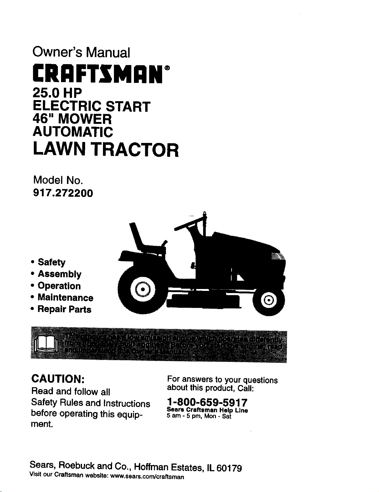
Owner's Manual
CRI:IFTZMAN°
25.0 HP
ELECTRIC START
46" MOWER
AUTOMATIC
LAWN TRACTOR
Model No.
917.272200
• Safety
• Assembly
• Operation
• Maintenance
• Repair Parts
CAUTION:
Read and follow all
Safety Rules and Instructions
before operating this equip-
ment.
For answers to your questions
about this product, Call:
1-800-659-5917
Sears Craftsman Help Line
5 am - 5 pm, Mon - Sat
Seam, Roebuck and Co., Hoffman Estates, IL 60179
Visit our Craftsman website: w_w_.sears.conVcreftsman
Warranty ............................................... 2
Safety Rules ......................................... 3
Product Specifications .......................... 5
Assembly .............................................. 7
Operation ............................................ 12
Maintenance Schedule ...................... 19
Maintenance ....................................... 19
Service and Adjustments .................... 23
Storage ............................................... 31
Troubleshooting .................................. 32
Repair Parts ........................................ 36
Parts Ordering ..................... Back Cover
LIMITED TWO YEAR WARRANTY ON CRAFTSMAN RIDING EQUIPMENT PARTS
For two (2) years from the date of purchase, if this Craftsman Riding Equipment is
maintained, lubricated and tuned up according to the instructions in the owner's
manual, Sears will repair or replace, free of charge, any parts found to be defective in
material or workmanship. Warranty service is available free of charge by taking your
Craftsman riding equipment to your nearest Sears Service Center. In-home warranty
service is available but a trip charge will apply. This warranty applies only while this
product is in the United States.
This Warranty does not cover:
• Expendable items which become worn during normal use, such as blades, spark
plugs, air cleaners, belts and oil filters.
• Tire replacement or repair caused by punctures from outside objects, such as nails,
thorns, stumps, or glass.
• Repairs necessary because of operator abuse, including but not limited to, damage
caused by towing objects beyond the capability of the riding equipment, impacting
objects that bend the frame or crankshaft, or over speeding the engine.
• Repairs necessary because of operator negligence, including but not limited to,
electrical and mechanical damage caused by improper storage, failure to use the
proper grade and amount of engine oil, failure to keep the deck clear of flammable
debris, or the failure to maintain the equipment according to the instructions con-
tained in the owner's manual.
• Engine (fuel system) cleaning or repairs caused by fuel determined to be contami-
nated or oxidized (stale), In general, fuel should be used within thirty (30) days of its
purchase date.
• Riding equipment used for commercial or rental purposes.
LIMITED 90 DAY WARRANTY ON BA3-1"ERY
For ninety (g0) days from date of pumhase, if any battery included with this riding
equipment proves defective in material or workmanship and our testing determines the
battery will not hold a charge, Sears will replace the battery at no charge. Warranty ser-
vice is available free of charge by taking your Craftsman riding equipment to your
nearest Sears Service Center. In-home warranty service is available but a trip charge
will apply. This warranty applies only while this product is in the United States.
To locate the nearest sears service center or to schedule in-home warranty service,
simply contact sears at 1-800-4-my-home
This Warranty gives you specific legal rights, and you may also have other rights which
may vary from state to state.
Sears, Roebuck and Co., D/817 WA, Hoffman Estates, IL 60179
IMPORTANT:Thiscuttingmachineis ca-
pable of amputating hands and feet and
throwing objects. Failure to observe the
following safety instructions could result
in serious injury or death.
GENERAL OPERATION
• Read, understand, and follow all in-
structions in the manual and on the
machine before starting.
• Only allow responsible adults, who are
familiar with the instructions, to oper-
ate the machine.
• Clear the area of objects such as
rocks, toys, wire, etc., which could be
picked up and thrown by the blade.
• Be sure the area is clear of other
people before mowing. Stop machine
if anyone enters the area.
• Never carry passengers.
• Do not mow in reverse unless abso-
lutely necessary. Always look down
and behind before and while backing.
• Be aware of the mower discharge di-
rection and do not point it at anyone.
Do not operate the mower without ei-
ther the entire grass catcher or the
guard in place.
• Slow down before turning.
• Never leave a running machine unat-
tended. Always turn off blades, set
parking brake, stop engine, and re-
move keys before dismounting.
• Turn off blades when not mowing.
• Stop engine before removing grass
catcher or unclogging chute.
• Mow only in daylight or good artificial
light.
• Do not operate the machine while un-
der the influence of alcohol or drugs.
• Watch for traffic when operating near
or crossing roadways.
• Use extra care when loading or un-
loading the machine into a trailer or
truck.
• Data indicates that operators, age 60
years and above, are involved in a
large percentage of riding mower-re-
lated injuries. These operators should
evaluate their ability to operate the
riding mower safely enough to protect
themselves and others from serious in-
jury.
SLOPE OPERATION
Slopes are a major factor related to loss-
of-control and tipover accidents, which
can result in severe injury or death. All
slopes require extra caution. If you can-
not back up the slope or if you feel un-
easy on it, do not mow it.
DO:
• Mow up and down slopes, not across.
• Remove obstacles such as rocks, tree
limbs, etc.
• Watch for holes, ruts, or bumps. Un-
even terrain could overturn the ma-
chine. Tall grass can hide obstacles.
• Use slow speed. Choose a low gear
so that you will not have to stop or shift
while on the slope.
• Follow the manufacturer's recommen-
dations for wheel weights or counter-
weights to improve stability.
• Use extra care with grass catchers or
other attachments. These can change
the stability of the machine.
* Keep all movement on the slopes slow
and gradual. Do not make sudden
changes in speed or direction.
• Avoid starting or stopping on a slope. If
tires lose traction, disengage the
blades and proceed slowly straight
down the slope.
DO NOT:
• Do not turn on slopes unless neces-
sary, and then, turn slowly and gradu-
ally downhill, if possible.
• Do not mow near drop-offs, ditches, or
embankments. The mower could sud-
denly turn over if a wheel is over the
edge of a cliff or ditch, or if an edge
caves in.
• Do not mow on wet grass. Reduced
traction could cause sliding.
• Do not try to stabilize the machine by
putting your foot on the ground.
• Do not use grass catcher on steep
slopes.
CHILDREN
Tragic accidents can occur if the operator
is not alert to the presence of children.
Children are often attracted to the ma-
chine and the mowing activity. Neveras-
sume that children will remain where you
last saw them,
3
• Keep children out of the mowing area
and under the watchful care of another
responsible adult.
• Be alert and turn machine off if children
enter the area.
• Before and when backing, look behind
and down for small children.
• Never carry children. They may fall off
and be seriously injured or interfere
with safe machine operation.
• Never allow children to operate the ma-
chine.
• Use extra care when approaching blind
corners, shrubs, trees, or other objects
that may obscure vision.
SERVICE
• Use extra care in handling gasoline
and other fuels. They are flammable
and vapors are explosive.
Use only an approved container.
Never remove gas cap or add fuel
with the engine running. Allow en-
gine to cool before refueling. Do not
smoke.
Never refuel the machine indoors.
Never store the machine or fuel
container inside where there is an
open flame, such as a water heater.
Never run a machine inside a closed
area.
Keep nuts and bolts, especially blade
attachment bolts, tight and keep equip-
ment in good condition.
Never tamper with safety devices.
Check their proper operation regularly.
Keep machine free of grass, leaves, or
other debris build-up. Clean oil or fuel
spillage. Allow machine to cool before
storing.
Stop and inspect the equipment if you
strike an object. Repair, if necessary,
before restarting.
Never make adjustments or repairs
with the engine running.
Grass catcher components are subject
to wear, damage, and deterioration,
which could expose moving parts or
allow objects to be thrown. Frequently
check components and replace with
manufacturer's recommended parts,
when necessary.
Mower blades are sharp and can cut.
Wrap the blade(s) or wear gloves, and
use extra caution when servicing
them.
• Check brake operation frequently.
Adjust and service as required.
• Be sure the area is clear of other
people before mowing. Stop machine
if anyone enters the area.
• Never carry passengers or children
even with the blades off.
• Do not mow in reverse unless abso-
lutely necessary. Always look down
and behind before and while backing,
• Never carry children. They may fall off
and be seriously injured or interfere
with safe machine operation.
• Keep children out of the mowing area
and under the watchful care of another
responsible adult.
• Be alert and turn machine off if chil-
dren enter the area.
• Before and when backing, look behind
and down for small children.
4
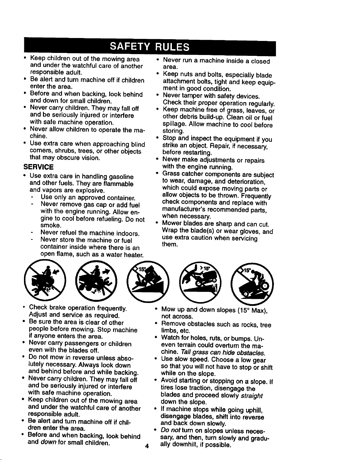
• Mow up and down slopes (15 ° Max),
not across.
• Remove obstacles such as rocks, tree
limbs, etc.
• Watch for holes, ruts, or bumps. Un-
even terrain could overturn the ma-
chine. Tall grass can hide obstacles.
• Use slow speed. Choose a low gear
so that you will not have to stop or shift
while on the slope.
• Avoid starting or stopping on a slope. If
tires lose traction, disengage the
blades and proceed slowly straight
down the slope.
• If machine stops while going uphill,
disengage blades, shift into reverse
and back down slowly.
• Do not turn on slopes unless neces-
sary, and then, turn slowly and gradu-
ally downhill, if possible.
_l,Look, for this symbol to point out impor-
tant sarety precautions. It means CAU-
TION!!! BECOME AWARE!!! YOUR
SAFETY IS INVOLVED.
Iad_IC.AUTION; In order to prevent acc!den-
starting wnen sening up, transporting,
adjusting or making repairs always dis-
connect spark plug wire and place wire
where it cannot contact spark plug.
_ILCAUTION- Do not coast down a hill in
neutral, you may lose control of the tractor.
_CAUTION: Tow onlythe attachments
that are recommenaed by ana comply
with specificationsof the manufacturer of
your tractor. Use common sense when
towing. Operate only at the lowest pos-
sible speed when on a slope. Too heavy of
a load, while on a slope, is dangerous.
Tires can lose traction withthe groundand
cause you to lose control ofyour tractor.
1AiWARN.ING:The engine exhaust from
s proouct comams cnem_cals Known to
the State of California to cause cancer,
birth defects, or other reproductive harm.
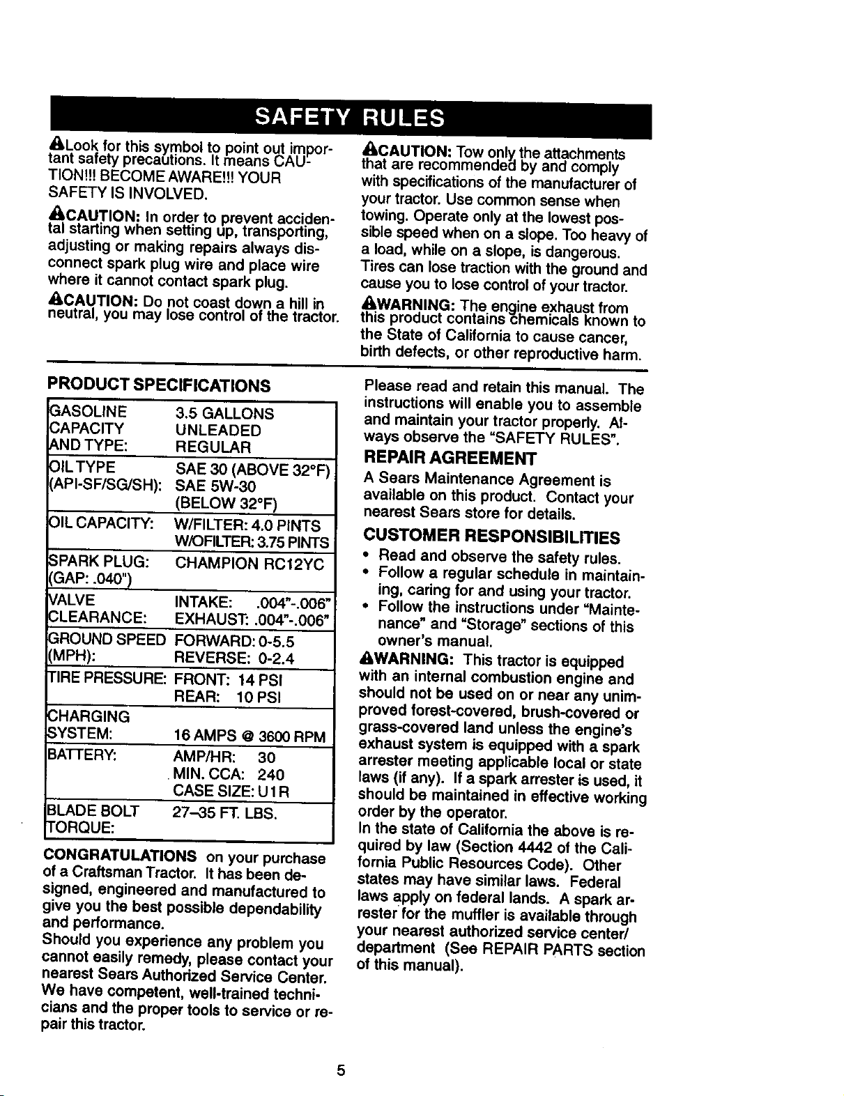
PRODUCT SPECIFICATIONS
3ASOLINE
3APACITY
_,ND TYPE:
31LTYPE
_,PI-SF/SG/SH):
DIL CAPACITY:
3.5 GALLONS
UNLEADED
REGULAR
SAE 30 (ABOVE 32°F
SAE 5W-30
(BELOW 32°F)
W/FILTER: 4.0 PINTS
WK)FILTER: 3.75 PINTS
SPARK PLUG: CHAMPION RC12YC
GAP: .040")
VALVE INTAKE: .004"-.006"
CLEARANCE: EXHAUST: .004"-.006"
GROUND SPEED FORWARD: 0-5.5
(MPH): REVERSE: 0-2.4
TIRE PRESSURE: FRONT: 14 PSI
REAR: 10 PSI
CHARGING
SYSTEM: 16 AMPS @ 3600 RPM
BA'_'ERY: AMP/HR: 30
•MIN. CCA: 240
CASE SIZE: U1R
BLADE BOLT 27-35 FT. LBS.
TORQUE:
CONGRATULATIONS on your purchase
of a Craftsman Tractor. It has been de-
signed, engineered and manufactured to
give you the best possible dependability
and performance.
Should you experience any problem you
cannot easily remedy, please contact your
nearest Sears Authorized Service Center.
We have competent, well-trained techni-
cians and the proper tools to service or re-
pair thistractor.
Please read and retain this manual. The
instructions will enable you to assemble
and maintain your tractor properly. At-
ways observe the "SAFETY RULES".
REPAIR AGREEMENT
A Sears Maintenance Agreement is
available on this product. Contact your
nearest Sears store for details.
CUSTOMER RESPONSIBILITIES
• Read and observe the safety rules.
• Follow a regular schedule in maintain-
ing, caring for and using your tractor.
• Follow the instructions under =Mainte-
nance" and "Storage" sections of this
owner's manual.
&,WARNING: This tractor is equipped
with an internal combustion engine and
should not be used on or near any unim-
proved forest-covered, brush-covered or
grass-covered land unless the engine's
exhaust system is equipped with a spark
arreeter meeting applicable local or state
laws (if any). If a spark arrester is used, it
should be maintained in effective working
order by the operator.
In the state of California the above is re-
quired by law (Section 4442 of the Cali-
fornia Public Resources Coda). Other
states may have similar laws. Federal
laws apply on federal lands. A spark at-
rester for the muffler is available through
your nearest authorized service center/
department (See REPAIR PARTS section
of this manual).
5
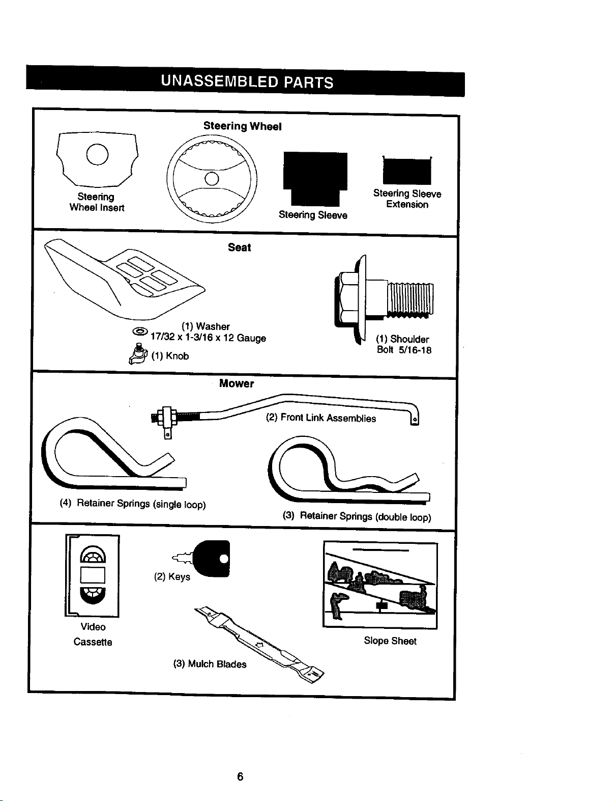
Steering
Wheel Insert
Steering Wheel
Steering Sleeve
Steering Sleeve
Extension
Seat
(1) Washer
17/32 x 1-3/16 x 12 Gauge
_(1) Knob
(1) Shoulder
Bolt 5/16-18
Mower
Front LinkAsse_
(4) Retainer Springs (singleloop)
(3) Retainer Springs (doubleloop)
r-7
Video
Casse_e
€
(2) Keys
(3) M_
Slope Sheet
6
Your new tractor has been assembled at the factory with exception of those parts left
unassembled for shipping purposes. To ensure safe and proper operation of your trac-
tor all parts and hardware you assemble must be tightened securely. Use the correct
tools as necessary to insure proper tightness. Review the video cassette before you
begin.
TOOLS REQUIRED FOR ASSEMBLY
A socket wrench set will make assembly
easier. Standard wrench sizes you need
are listed below.
(1) 3/4" wrench
(2) 112" wrench
(1) Utility knife
(1) Pliers
(1) 9/16" wrench
(1) 3/4" Socket w/
drive rachet
(1) Phillips Screw-
driver
(1) Tire pressure
gauge
When right or left hand is mentioned in
this manual, it means, from your point of
view, when you are in the operating posi-
tion (seated behind the steering wheel).
TO REMOVE TRACTOR FROM CARTON
UNPACK CARTON
• Remove all accessible loose parts and
parts boxes from shipping carton.
• Cut, from top to bottom, along lines on
all four comers of shipping carton, and
lay panels flat.
• Remove mower and package materi-
als.
• Check for any additional loose parts or
boxes and remove.
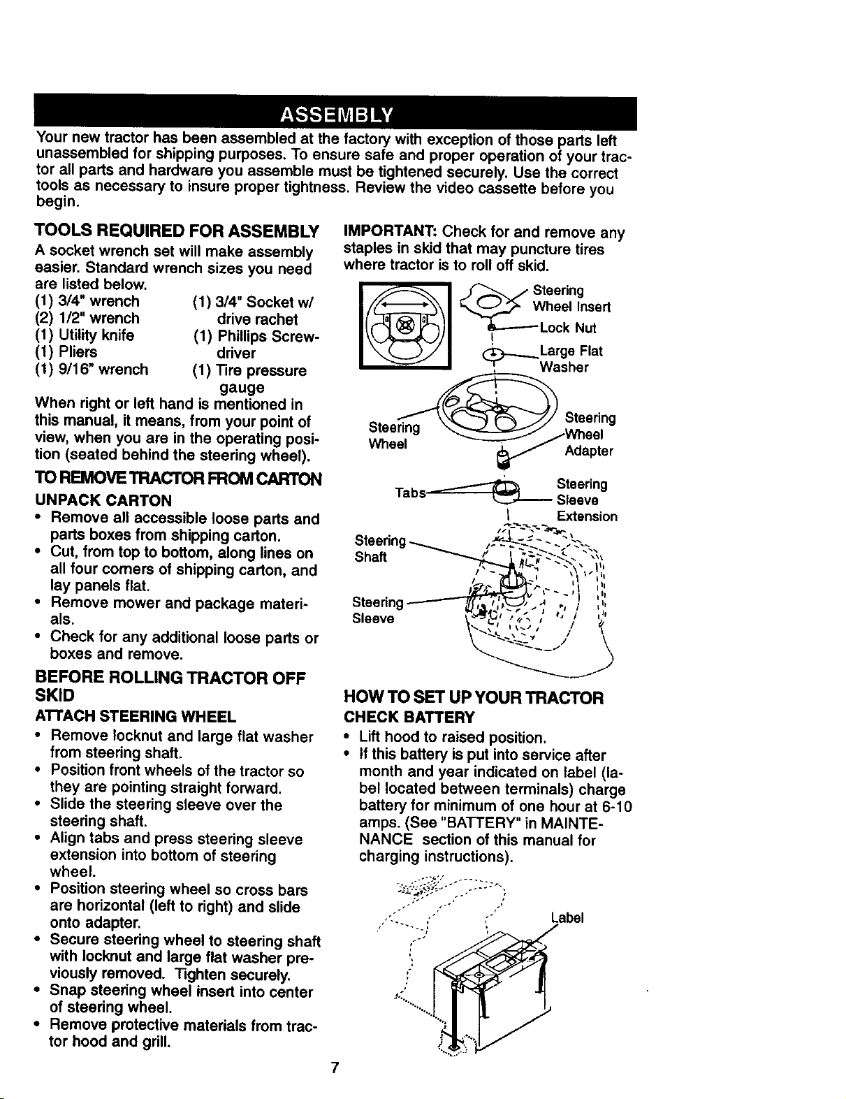
IMPORTANT: Check for and remove any
staples in skid that may puncture tires
where tractor is to roll off skid.
Steering
heel Insert
Lock Nut
I
. _ Stesdng
_/_" Adapter
Steering
Tabs_---_ _ Sleeve
I Extension
BEFORE ROLLING TRACTOR OFF
SKID
ATTACH STEERING WHEEL
• Remove Iocknut and large flat washer
from steering shaft.
• Position front wheels of the tractor so
they are pointing straight forward.
• Slide the steering sleeve over the
steering shaft.
• Align tabs and press steering sleeve
extension into bottom of steering
wheel.
• Position steering wheel so cross bars
are horizontal (left to right) and slide
onto adapter.
• Secure steering wheel to steering shaft
with Iocknut and large flat washer pre-
viously removed. Tighten securely.
• Snap steering wheel insert into center
of steering wheel.
• Remove protective materials from trac-
tor hood and grill.
HOW TO SET UP YOUR TRACTOR
CHECK BATTERY
• Lift hood to raised position.
• If this battery is put into service after
month and year indicated on label (la-
bel located between terminals) charge
battery for minimum of one hour at 6-10
amps, (See "BATTERY" in MAINTE-
NANCE section of this manual for
charging instructions).
2: " '
"" "" ' Label
7
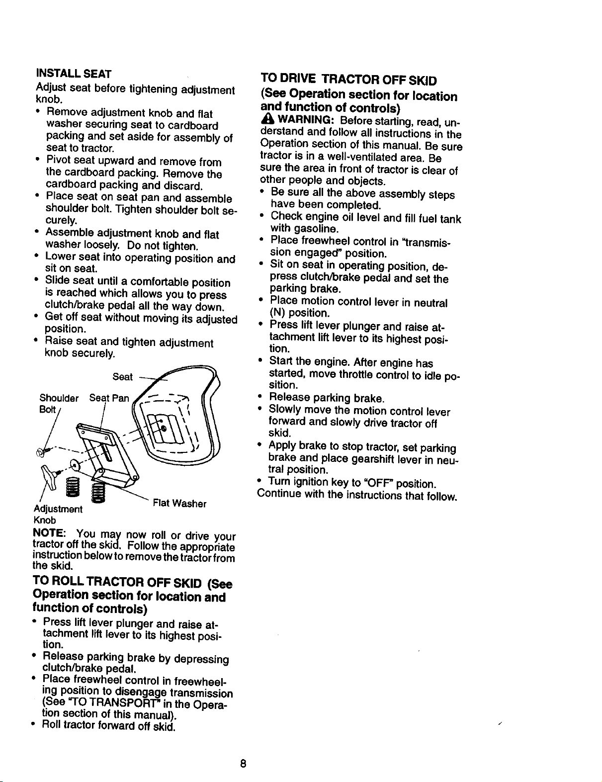
INSTALLSEAT
Adjustseatbeforetighteningadjustment
knob.
• Remove adjustment knob and flat
washer securing seat to cardboard
packing and set aside for assembly of
seat to tractor.
• Pivot seat upward and remove from
the cardboard packing. Remove the
cardboard packing and discard.
• Place seat on seat pan and assemble
shoulder bolt. Tighten shoulder bolt se-
curely.
• Assemble adjustment knob and flat
washer loosely. Do not tighten.
• Lower seat into operating position and
sit on seat,
• Slide seat until a comfortable position
is reached which allows you to press
clutch/brake pedal all the way down.
• Get off seat without moving its adjusted
position.
• Raise seat and tighten adjustment
knob securely.
Seat
Shoulder Seat Pan
Bolt
Flat Washer
Adjustment
Knob
NOTE: You may now roll or drive your
tractor off the skid. Follow the appropriate
instruction below to remove the tractor from
the skid.
TO ROLL TRACTOR OFF SKID (See
Operation section for location and
function of controls)
• Press lift lever plunger and raise at-
tachment lift lever to its highest posi-
tion.
• Release parking brake by depressing
clutch/brake pedal.
• Place freewheel control in freewheel-
ing position to disengage transmission
(See "TO TRANSPORT" in the Opera-
tion section of this manual).
• Roll tractor forward off skid.
TO DRIVE TRACTOR OFF SKID
(See Operation section for location
and function of controls)
WARNING: Before starting, read, un-
derstand and follow all instructions in the
Operation section of this manual. Be sure
tractor is in a well-ventilated area. Be
sure the area in front of tractor is clear of
other people and objects.
• Be sure all the above assembly steps
have been completed.
• Check engine oil level and fill fuel tank
with gasoline.
• Place freewheel control in "transmis-
sion engaged" position.
• Sit on seat in operating position, de-
press clutch/brake pedal and set the
parking brake.
• Place motion control lever in neutral
(N) position.
• Press lift lever plunger and raise at-
tachment lift lever to its highest posi-
tion.
• Start the engine. After engine has
started, move throttle control to idle po-
sition.
• Release parking brake.
• Slowly move the motion control lever
forward and slowly drive tractor off
skid.
• Apply brake to stop tractor, set parking
brake and place gearshift lever in neu-
tral position.
• Turn ignition key to "OFF" position.
Continue with the instructions that follow.
8
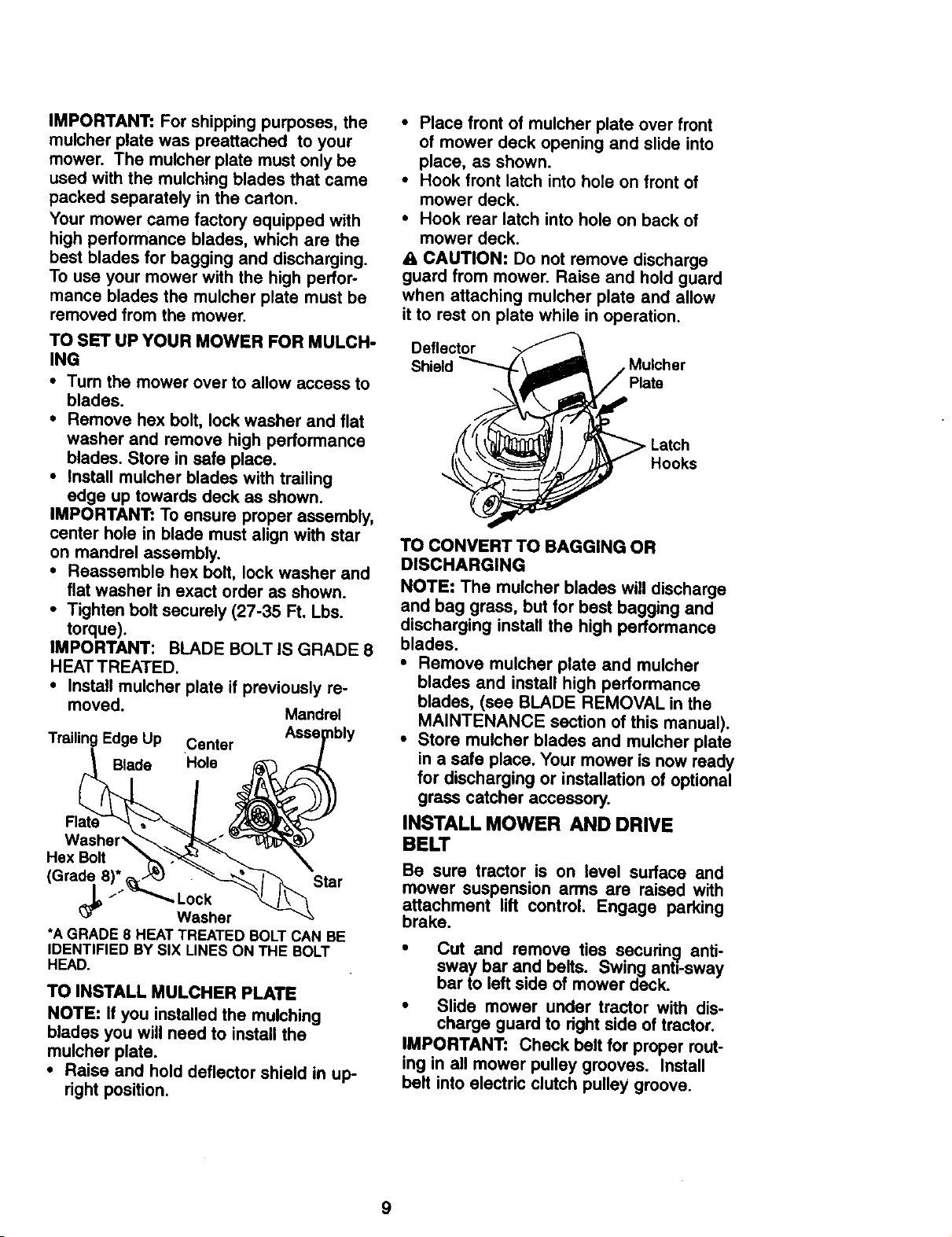
IMPORTANT: For shipping purposes, the
mulcher plate was preattached to your
mower. The mutcher plate must only be
used with the mulching blades that came
packed separately in the carton.
Your mower came factory equipped with
high performance blades, which are the
best blades for bagging and discharging.
To use your mower with the high perfor-
mance blades the mulcher plate must be
removed from the mower.
TO SET UP YOUR MOWER FOR MULCH-
ING
• Turn the mower over to allow access to
blades.
• Remove hex bolt, lock washer and flat
washer and remove high performance
blades. Store in safe place.
• Install mutcher blades with trailing
edge up towards deck as shown.
IMPORTANT: To ensure proper assembly,
center hole in blade must align with star
on mandrel assembly.
• Reassemble hex bolt, lock washer and
flat washer in exact order as shown.
• Tighten bolt securely (27-35 Ft. Lbs.
torque),
IMPORTANT: BLADE BOLT IS GRADE 8
HEATTREATED.
• Install mulcher plate if previously re-
moved. Mandrel
TrailingEdge Up Center
Blade
Washer'_
Hex Bolt
Star
Lock
Washer
*A GRADE 8 HEATTREATED BOLTCAN BE
IDENTIFIED BY SIX LINES ON THE BOLT
HEAD.
TO INSTALL MULCHER PLATE
NOTE: If you installed the mulching
blades you will need to install the
mulcher plate.
• Raise and hold deflector shield in up-
right position.
• Place front of mulcher plate over front
of mower deck opening and slide into
place, as shown.
• Hook front latch into hole on front of
mower deck.
• Hook rear latch into hole on back of
mower deck.
& CAUTION: Do not remove discharge
guard from mower. Raise and hold guard
when attaching mulcher plate and allow
it to rest on plate while in operation.
Deflector
Shield Mulcher
,- Latch
Hooks
TO CONVERT TO BAGGING OR
DISCHARGING
NOTE: The mulcher blades will discharge
and bag grass, but for best bagging and
discharging install the high performance
blades.
• Remove mulcher plate and mulcher
blades and install high performance
blades, (see BLADE REMOVAL in the
MAINTENANCE section of this manual).
• Store mulcher blades and mulcher plate
in a safe place. Your mower is now ready
for discharging or installation of optional
grass catcher accessory.
INSTALL MOWER AND DRIVE
BELT
Be sure tractor is on level surface and
mower suspension arms are raised with
attachment lift control. Engage parking
brake.
• Cut and remove ties secudng anti-
sway bar and belts. Swing anti-sway
bar to left side of mower deck.
• Slide mower under tractor with dis-
charge guard to dght side of tractor.
IMPORTANT: Check belt for proper rout-
ing in all mower pulley grooves. Install
belt into electric clutch pulley groove.
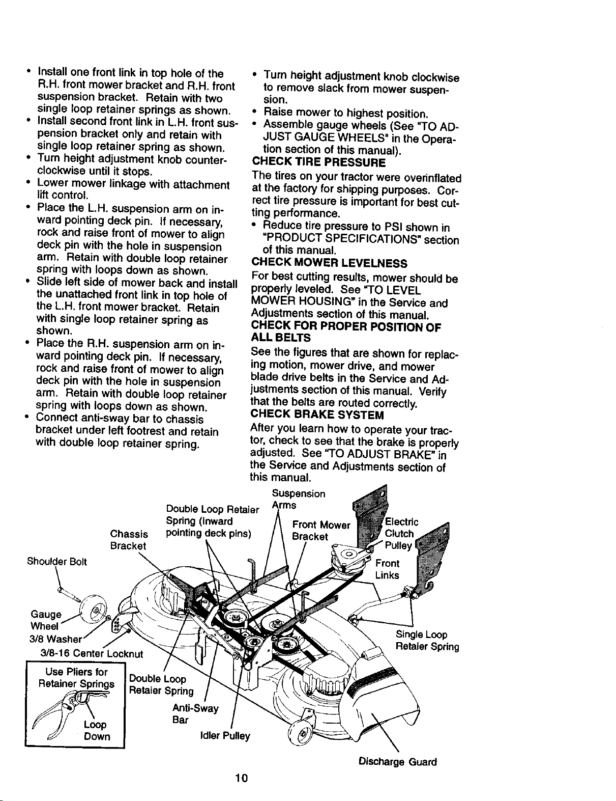
• Install one front link in top hole of the
R.H. front mower bracket and R.H. front
suspension bracket. Retain with two
single loop retainer springs as shown.
• Install second front link in L.H. front sus-
pension bracket only and retain with
single loop retainer spring as shown.
• Turn height adjustment knob counter-
clockwise until it stops.
• Lower mower linkage with attachment
lift control.
• Place the L.H, suspension arm on in-
ward pointing deck pin. If necessary,
rock and raise front of mower to align
deck pin with the hole in suspension
arm. Retain with double loop retainer
spring with loops down as shown.
• Slide left side of mower back and install
the unattached front link in top hole of
the L.H. front mower bracket. Retain
with single loop retainer spring as
shown.
• Place the R.H. suspension arm on in-
ward pointing deck pin. If necessary,
rock and raise front of mower to align
deck pin with the hole in suspension
arm. Retain with double loop retainer
spring with loops down as shown.
• Connect anti-sway bar to chassis
bracket under left footrest and retain
with double loop retainer spring.
Chassis
Bracket
• Turn height adjustment knob clockwise
to remove slack from mower suspen-
sion.
• Raise mower to highest position.
• Assemble gauge wheels (See "TO AD-
JUST GAUGE WHEELS" in the Opera-
tion section of this manual).
CHECK TIRE PRESSURE
The tires on your tractor were ovednflated
at the factory for shipping purposes. Cor-
rect tire pressure is important for best cut-
ting performance.
• Reduce tire pressure to PSI shown in
"PRODUCT SPECIFICATIONS" section
of this manual.
CHECK MOWER LEVELNESS
For best cutting resultS, mower should be
properly leveled. See =TO LEVEL
MOWER HOUSING" in the Service and
Adjustments section of this manual.
CHECK FOR PROPER POSITION OF
ALL BELTS
See the figures that are shown for replac-
ing motion, mower drive, and mower
blade drive belts in the Service and Ad-
justments section of this manual. Verify
that the belts are routed correctly.
CHECK BRAKE SYSTEM
After you learn how to operate your trac-
tor, check to see that the brake is properly
adjusted. See "TO ADJUST BRAKE" in
the Service and Adjustments section of
this manual.
Double Loop Retaier
Spring (Inward
pointing deck pins)
Suspension
Arms
Front Mower
Bracket
Shoulder Bolt
3/8
3/8-16 Center Locknut
Use Pliers for
Retainer Springs
Double Loop
Retaier Spring
Anti-Sway
Bar
Idler Pulley
10
Single Loop
Retaier Spring
Discharge Guard
CHECKLIST
BEFORE YOU OPERATE AND ENJOY
YOUR NEW TRACTOR, WE WISH TO
ASSURE THAT YOU RECEIVE THE
BEST PERFORMANCE AND SATISFAC-
TION FROM THIS QUALITY PRODUCT.
PLEASE REVIEW THE FOLLOWING
CHECKLIST:
/ All assembly instructions have been
completed.
/ No remaining loose parts in carton.
/ Battery is properly prepared and
charged. (Minimum 1 hour at 6
amps).
/ Seat is adjusted comfortably and tight-
ened securely.
,/All tires are properly inflated. (For
shipping purposes, the tires were
overinflated at the factory).
,/Be sure mower deck is properly lev-
eled side-to-side/front-to-rear for best
cutting results. (Tires must be properly
inflated for leveling).
,/Check mower and drive belts. Be sure
they are routed properly around pul-
leys and inside all belt keepers.
,/Check wiring. See that all connections
are still secure and wires are properly
clamped.
,/Before driving tractor, be sure free-
wheel control is in drive position.
WHILE LEARNING HOW TO USE YOUR
TRACTOR, PAY EXTRAA'I-FENTION TO
THE FOLLOWING IMPORTANT ITEMS:
,/Engine oil is at proper level.
4 Fuel tank is filled with fresh, clean,
regular unleaded gasoline.
,/Become familiar with all controls - their
location and function. Operate them
before you start the engine.
/ Be sure brake system is in safe operat-
ing condition,
,/It is important to purge the transmis-
sion before operating your tractor for
the first time. Follow proper starting
and transmission purging instructions
(See "TO START ENGINE" and
"PURGE TRANSMISSION" in the Op-
eration section of this manual).
11
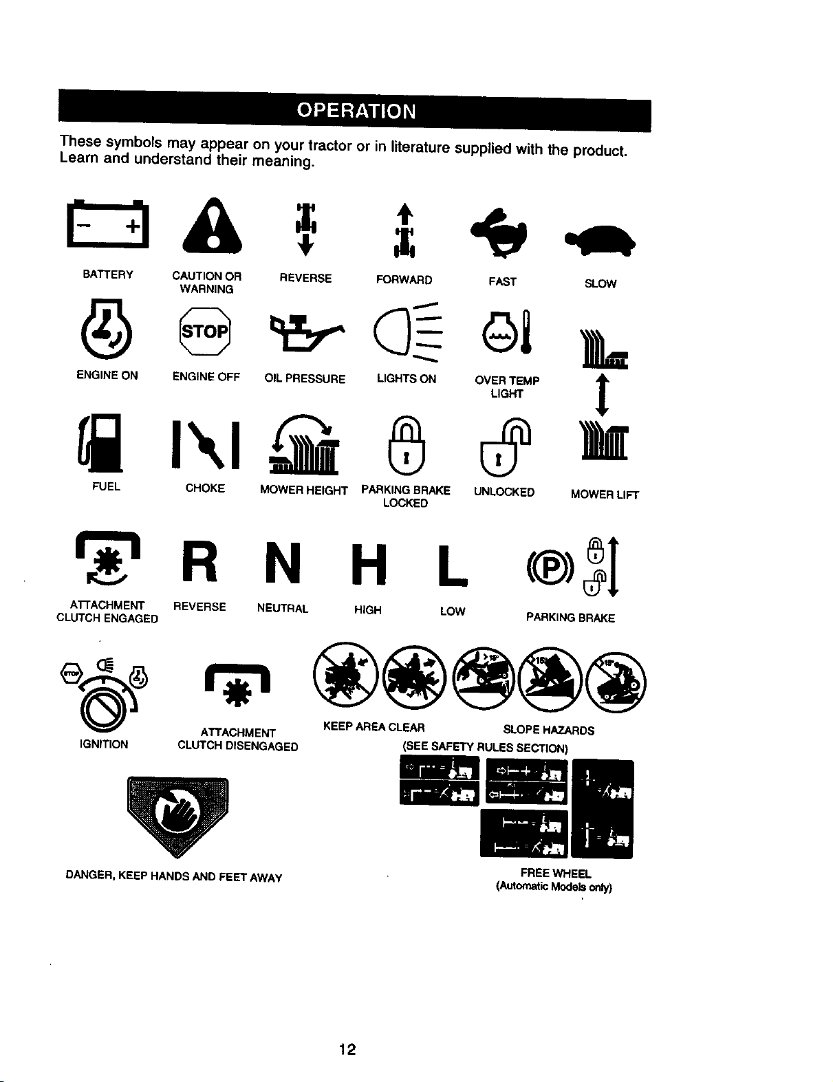
Thesesymbolsmay appear on your tractor or in literature supplied with the product.
Learn and understand their meaning.
BATTERY CAUTION OR REVERSE FORWARD FAST SLOW
WARNING
ENG,NE_j_ON_IENG'NEOFFO,L_PRESSUREL.GNTS_ONO%T_.P_
FUEL CHOKE MOWER HEIGHT PARKING BRAKE UNLOCKED MOWER LIFT
LOCKED
R N H L
ATTACHMENT REVERSE NEUTRAL HIGH LOW
CLUTCH ENGAGED PARKING BRAKE
ATTACHMENT KEEP AREA CLEAR SLOPE HAZARDS
IGNITION CLUTCH DISENGAGED (SEE SAFETY RULES SECTION)
DANGER, KEEP HANDS AND FEET AWAY
FREE WHEEL
(AutomaticModelsonly)
12
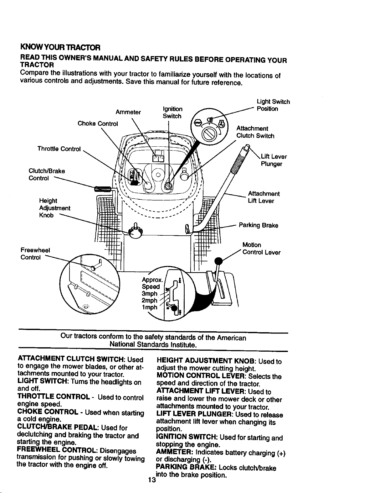
KNOWYOURTRACTOR
READTHISOWNER'SMANUALANDSAFETYRULESBEFOREOPERATINGYOUR
TRACTOR
Comparetheillustrationswithyourtractorto familiarizeyourselfwiththe locations of
various controls and adjustments. Save this manual for future reference.
Ignition
Ammeter Switch
Choke Control
Light Switch
Posi_on
Attachment
Clutch Switch
Throttle Control
Clutch/Brake
Control
Height
Adjustment
Knob
Lift Lever
Plunger
Attachment
Lift Lever
Parking Brake
Freewheel
Control
Moron
/ Control Lever
Approx.
Speed
3mph ---
2mph St I
1mph
Our tractors conformto the safety standards of the Amedcan
National Standards Institute.
ATTACHMENT CLUTCH SWITCH: Used
to engage the mower blades, or other at-
tachments mounted to your tractor.
LIGHT SWITCH: Turns the headlights on
and off.
THROTTLE CONTROL - Used to control
engine speed.
CHOKE CONTROL - Used when starting
a cold engine.
CLUTCH/BRAKE PEDAL: Used for
declutching and braking the tractor and
starting the engine.
FREEWHEEL CONTROL: Disengages
transmission for pushing or slowly towing
the tractor with the engine off.
HEIGHT ADJUSTMENT KNOB: Used to
adjust the mower cuffing height.
MOTION CONTROL LEVER: Selects the
speed and direction of the tractor.
ATTACHMENT LIFT LEVER: Used to
raise and lower the mower deck or other
attachments mounted to your tractor.
LIFT LEVER PLUNGER: Used to release
attachment lift lever when changing its
position.
IGNITION SWITCH: Used for starting and
stopping the engine.
AMMETER: Indicates battery charging (+)
or discharging (-).
PARKING BRAKE: Locks clutch/brake
into the brake position.
13
The operation of any tractor can result in foreign objects thrown into the I
eyes, which can result in severe eye damage. Always wear safety glasses |
or eye shields while operating your tractor or performing any adjustments I
or repairs. We recommend a wide vision safety mask over spectacles, or |
standard safety glasses.
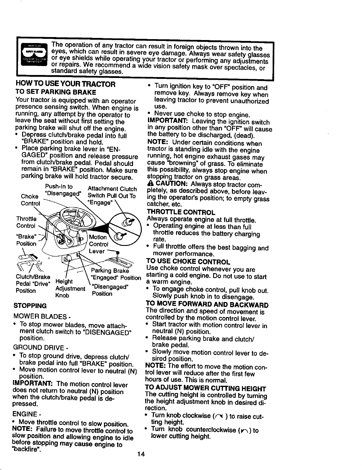
HOW TO USE YOUR TRACTOR
TO SET PARKING BRAKE
Your tractor is equipped with an operator
presence sensing switch. When engine is
running, any attempt by the operator to
leave the seat without first setting the
parking brake will shut off the engine.
• Depress clutch/brake pedal into full
=BRAKE" position and hold.
• Place parking brake lever in "EN-
GAGED" position and release pressure
from clutch/brake pedal. Pedal should
remain in "BRAKE" position. Make sure
parking brake will hold tractor secure.
Attachment Clutch
Switch Pull Out To
Push-in to
Choke =Disengagt
Control
Throttle
Control
Parking Brake
=Engaged" Position
"Disengaged"
Position
Clutch/Brake
Pedal "Ddve" Height
Position Adjustment
Knob
STOPPING
MOWER BLADES -
• To stop mower blades, move attach-
ment clutch switch to "DISENGAGED"
position.
GROUND DRIVE -
• To stop ground drive, depress clutch/
brake pedal into full "BRAKE" position.
• Move motion control lever to neutral (N)
position.
IMPORTANT: The motion control lever
does not return to neutral (N) position
when the clutch/brake pedal is de-
pressed.
ENGINE -
• Move throttle control to slow position.
NOTE: Failure to move throttle control to
slow position and allowing engine to idle
before stopping may cause engine to
"backfire'.
• Turn ignition key to "OFF" position and
remove key. Always remove key when
leaving tractor to prevent unauthorized
use.
• Never use choke to stop engine.
IMPORTANT: Leaving the ignition switch
in any position other than "OFF" will cause
the battery to be discharged, (dead).
NOTE: Under certain conditions when
tractor is standing idle with the engine
running, hot engine exhaust gases may
cause "browning" of grass. To eliminate
this possibility, always stop engine when
stopping tract.or on grass areas.
A, CAUTION, Always stop tractor com-
pletely, as described above, before leav-
ing the operator's position; to empty grass
catcher, etc.
THROTTLE CONTROL
Always operate engine at full throttle.
• Operating engine at less than full
throttle reduces the battery charging
rate.
• Full throttle offers the best bagging and
mower performance.
TO USE CHOKE CONTROL
Use choke control whenever you are
starting a cold engine. Do not use to start
a warm engine.
• To engage choke control, pull knob out.
Slowly push knob in to disengage.
TO MOVE FORWARD AND BACKWARD
The direction and speed of movement is
controlled by the motion control lever.
• Start tractor with motion control lever in
neutral (N) position.
• Release parking brake and clutch/
brake pedal,
• Slowly move motion control lever to de-
sired position.
NOTE: The effort to move the motion con-
trol lever will reduce after the first few
hours of use. This is normal.
TO ADJUST MOWER cUTrlNG HEIGHT
The cutting height is controlled by turning
the height adjustment knob in desired di-
rection.
• Turn knob clockwise ((_) to raise cut-
ting height.
• Turn knob counterclockwise (_,-_) to
lower cutting height.
14
The cutting height range is approximately
1-1/2" to 4". The heights are measured
from the ground to the blade tip with the
engine not running. These heights are
approximate and may vary depending
upon soil conditions, height of grass and
types of grass being mowed.
• The average lawn should be cut to ap-
proximately 2-1/2 inches during the
cool season and to over 3 inches dur-
ing hot months. For healthier and bet-
ter looking lawns, mow often and after
moderate growth.
• For best cutting performance, grass
over 6 inches in height should be
mowed twice. Make the first cut rela-
tively high; the second to desired
height,
TO ADJUST GAUGE WHEELS
Gauge wheels are properly adjusted
when they are slightly off the ground
when mower Is at the desired cutting
height in operating position. Gauge
wheels then keep the deck in proper po-
sition to help prevent scalping in most ter-
rain conditions.
• Adjust gauge wheels with tractor on a
flat level surface.
• Adjust mower to desired cutting height
(See =TO ADJUST MOWER CUTI'ING
HEIGHT" in the Operation section of
this manual).
• With mower in desired height of cut po-
sition, gauge wheels should be as-
sembled so they are slightly off the
ground, install gauge wheel in appro-
priate hole with shoulder bolt, 3/8
washer, and 3/8-16 Iocknut and tighten
securely.
• Repeat for opposite side installing
gauge wheel in same adjustment hole.
Gauge Wheel
Mounting
Bracket
3/8-16
Locknut
3/8 Washer Gauge Wheel
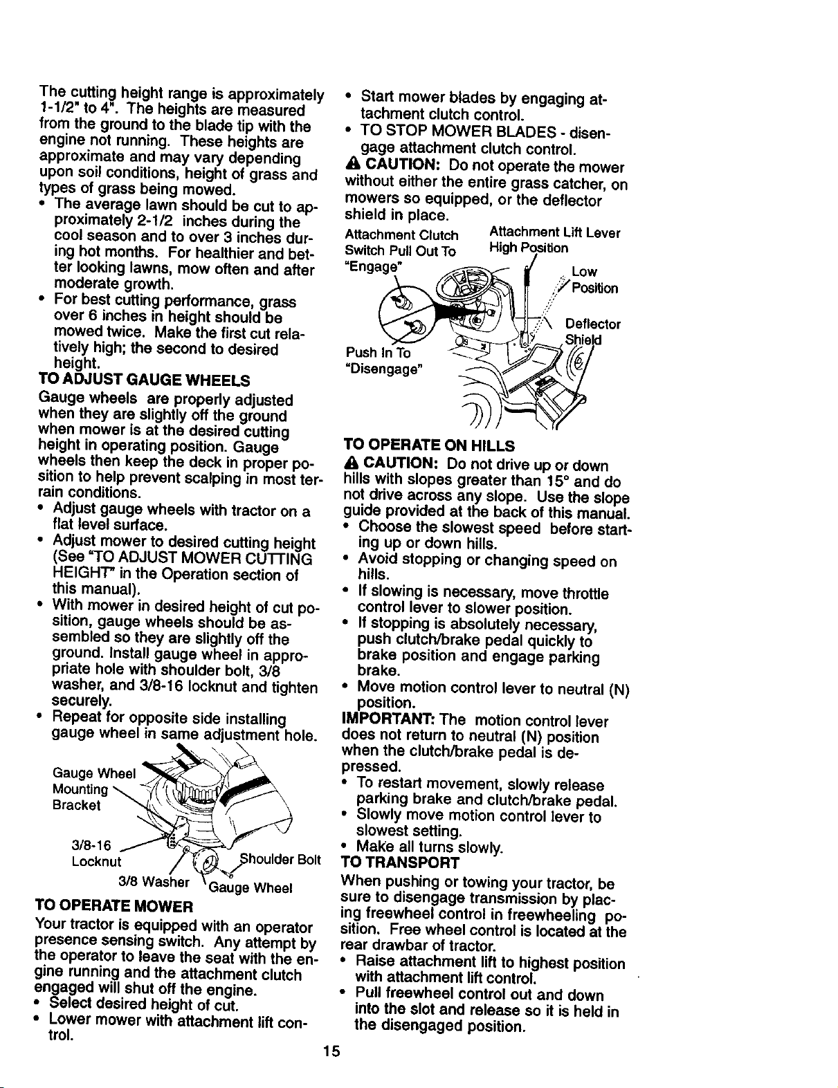
TO OPERATE MOWER
Your tractor is equipped with an operator
presence sensing switch. Any attempt by
the operator to leave the seat with the en-
gine running and the attachment clutch
engaged will shut oft the engine.
• Select desired height of cut.
• Lower mower with attachment lift con-
trol.
• Start mower blades by engaging at-
tachment clutch control.
• TO STOP MOWER BLADES - disen-
gage attachment clutch control.
A CAUTION: Do not operate the mower
without either the entire grass catcher, on
mowers so equipped, or the deflector
shield in place.
Attachment Clutch Attachment Lift Lever
Switch Pull Out To High Position
=Enga_ _.-..." Low
,;;_ Position
- ":X Deflector
_" Shield
Push In To _ I . I/_-_/_/
TO OPERATE ON HILLS
_, CAUTION: Do not drive up or down
hills with slopes greater than 15° and do
not drive across any slope. Use the slope
guide provided at the back of this manual.
• Choose the slowest speed before start-
ing up or clown hills.
• Avoid stopping or changing speed on
hills.
• If slowing is necessary, move throttle
control lever to slower position.
• If stopping is absolutely necessary,
push clutch/brake pedal quickly to
brake position and engage parking
brake.
• Move motion control lever to neutral (N)
position.
IMPORTANT: The motion control lever
does not return to neutral (N) position
when the clutch/brake pedal is de-
pressed,
• To restart movement, slowly release
parking brake and clutch/brake pedal.
• Slowly move motion control lever to
slowest setting.
• Make all turns slowly.
TO TRANSPORT
When pushing or towing your tractor, be
sure to disengage transmission by plac-
ing freewheel control in freewheeling po-
sition. Free wheel control is located at the
rear drawbar of tractor.
• Raise attachment lift to highest position
with attachment lift control.
• Pull freewheel control out and down
into the slot and release so it is held in
the disengaged position.
15
• Do not push or tow tractor at more than
two (2) MPH.
• To reengage transmission, reverse
above procedure.
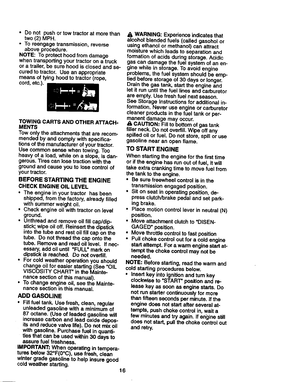
NOTE: To protect hood from damage
when transporting your tractor on a truck
or a trailer, be sure hood is closed and se-
cured to tractor. Use an appropriate
means of tying hood to tractor (rope,
cord, etc.).
TOWING CARTS AND OTHER ATTACH-
MENTS
Tow only the attachments that are recom-
mended by and comply with specifica-
tions of the manufacturer of your tractor.
Use common sense when towing. Too
heavy of a load, while on a slope, is dan-
gerous. Tires can lose traction with the
ground and cause you to lose control of
your tractor.
BEFORE STARTING THE ENGINE
CHECK ENGINE OIL LEVEL
• The engine in your tractor has been
shipped, from the factory, already filled
with summer weight oil.
• Check engine oil with tractor on level
ground.
• Unthread and remove oil fill cap/dip-
stick_ wipe oil off. Reinsert the dipstick
into the tube and rest oil fill cap on the
tube. Do not thread the cap onto the
tube. Remove and read oil level. If nec-
essary, add oil until "FULL" mark on
dipstick is reached. Do not overfill.
• For cold weather operation you should
change oil for easier starting (See "OIL
VISCOSITY CHART" in the Mainte-
nance section of this manual).
• To change engine oil, see the Mainte-
nance section in this manual.
ADD GASOLINE
• Fill fuel tank. Use fresh, clean, regular
unleaded gasoline with a minimum of
87 octane. (Use of leaded gasoline will
increase carbon and lead oxide depos-
its and reduce valve life). Do not mix oil
with gasoline. Purchase fuel in quanti-
ties that can be used within 30 days to
assure fuel freshness.
IMPORTANT: When operating in tempera-
tures below 32°F(0°C), use fresh, clean
winter grade gasoline to help insure good
cold weather starting.
16
WARNING: Experience indicates that
alcohol blended fuels (called gasohol or
using ethanol or methanol) can attract
moisture which leads to separation and
formation of acids during storage. Acidic
gas can damage the fuel system of an en-
gine while in storage. To avoid engine
problems, the fuel system should be emp-
tied before storage of 30 days or longer.
Drain the gas tank, start the engine and
let it run until the fuel lines and carburetor
are empty. Use fresh fuel next season.
See Storage instructions for additional in-
formation. Never use engine or carburetor
cleaner products in the fuel tank or per-
manent damage may occur.
CAUTION: Fill to bottom of gas tank
filler neck. Do not ovediit. Wipe off any
spilled oil or fuel. Do not store, spill or use
gasoline near an open flame.
TO START ENGINE
When starting the engine for the first time
or if the engine has run out of fuel, it will
take extra cranking time to move fuel from
the tank to the engine.
• Be sure freewheel control is in the
transmission engaged position.
* Sit on seat in operating position, de-
press clutch/brake pedal and set park-
ing brake.
• Place motion control lever in neutral (N)
position.
• Move attachment clutch to =DISEN-
GAGED" position.
• Move throttle control to fast position
• Pull choke control out for a cold engine
start attempt. For a warm engine start at-
tempt the choke control may not be
needed.
NOTE: Before starting, read the warm and
cold starting procedures below.
• Insert key into ignition and tum key
clockwise to =START" position and re-
lease key as soon as engine starts. Do
not run starter continuously for more
than fifteen seconds per minute. If the
engine does not start after several at-
tempts, push choke control in, wait a
few minutes and try again. If engine still
does not start, pull the choke control out
and retry.
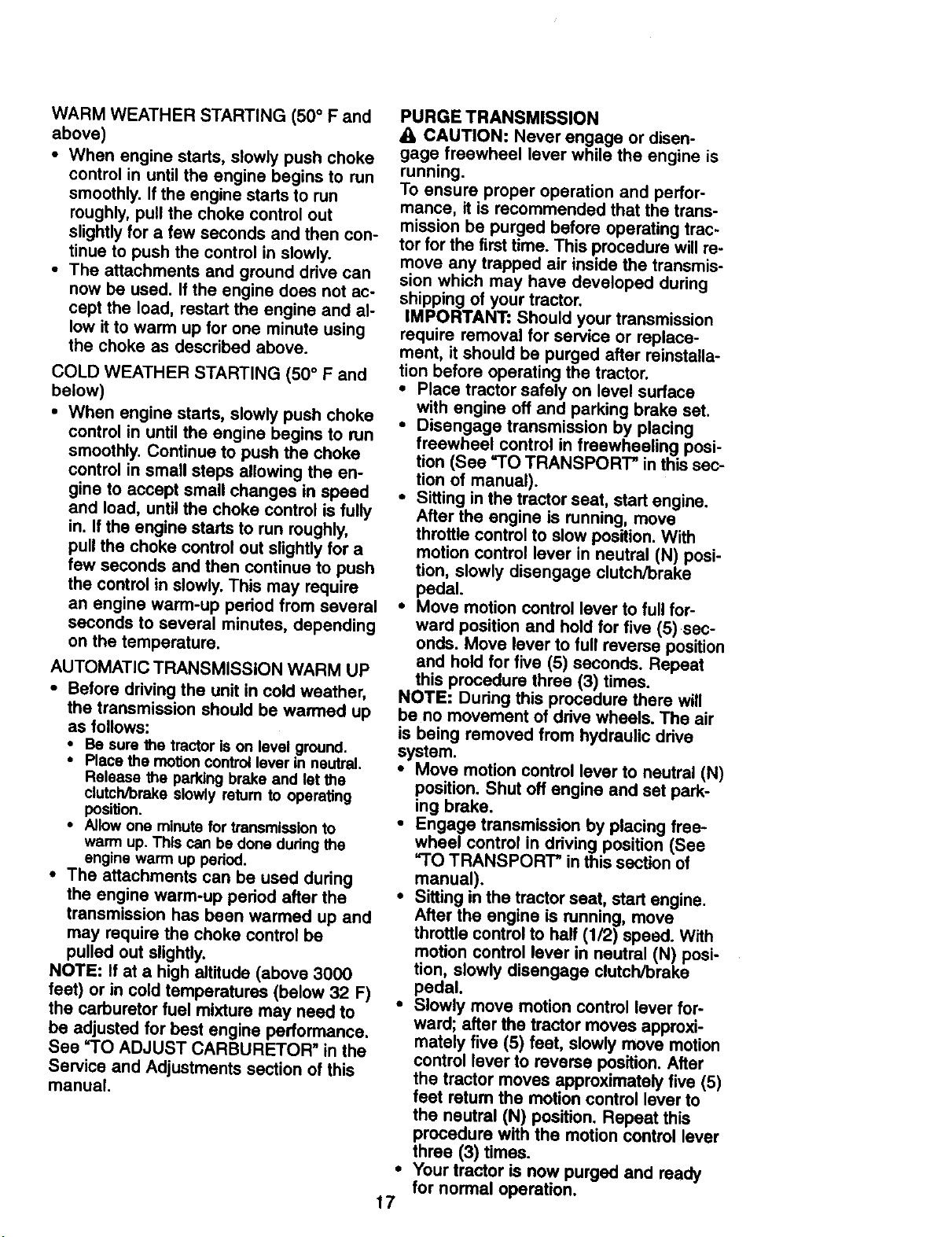
WARM WEATHER STARTING (50 ° F and
above)
• When engine stads, slowly push choke
control in until the engine begins to run
smoothly. If the engine starts to run
roughly, pull the choke control out
slightly for a few seconds and then con-
tinue to push the control in slowly.
• The attachments and ground drive can
now be used. If the engine does not ac-
cept the load, restart the engine and al-
low it to warm up for one minute using
the choke as described above.
COLD WEATHER STARTING (50 ° F and
below)
• When engine starts, slowly push choke
control in until the engine begins to run
smoothly. Continue to push the choke
control in small steps allowing the en-
gine to accept small changes in speed
and load, until the choke control is fully
in. If the engine starts to run roughly,
pull the choke control out slightly for a
few seconds and then continue to push
the control in slowly. This may require
an engine warm-up pedod from several
seconds to several minutes, depending
on the temperature.
AUTOMATIC TRANSMISSION WARM UP
• Before driving the unit in cold weather,
the transmission should be warmed up
as follows:
• Be sure the tractor is on level ground.
• Place the motion control lever in neutral,
Release the parking brake and tel the
clutch/brake slowly return to operating
position.
• Allow one minute for transmission to
warm up. This can be done during the
engine warm up pedod.
• The attachments can be used dudng
the engine warm-up pedod after the
transmission has been warmed up and
may require the choke control be
pulled out slightly.
NOTE: if at a high altitude (above 3000
feet) or in cold temperatures (below 32 F)
the carburetor fuel mixture may need to
be adjusted for best engine performance,
See "TO ADJUST CARBURETOR" in the
Service and Adjustments section of this
manual.
PURGE TRANSMISSION
_lbCAUTION: Never engage or disen-
gage freewheel lever while the engine is
running.
To ensure proper operation and perfor-
mance, it is recommended that the trans-
mission be purged before operating trac-
tor forthe first time. This procedure will re-
move any trapped air inside the transmis-
sion which may have developed during
shipping of your tractor.
IMPORTANT: Should your transmission
require removal for service or replace-
ment, itshould be purged after reinstalla-
tion before operating the tractor.
• Place tractor safely on level surface
with engine off and parking brake set.
• Disengage transmission by placing
freewheel control in freewheeling posi-
tion (See "TO TRANSPORT" in thissec-
tion of manual).
• Sitting in the tractor seat, start engine.
After the engine is running, move
throttle control to slow position. With
motion control lever in neutral (N) posi-
tion, slowly disengage clutch/brake
pedal.
• Move motion control lever to full for-
ward position and hold for five (5)sec-
onds. Move lever to full reverse position
and hold for five (5) seconds. Repeat
this procedure three (3) times.
NOTE: Dudng this procedure there will
be no movement of drive wheels. The air
is being removed from hydraulic drive
system.
• Move motion control lever to neutral (N)
position. Shut oft engine and set park-
ing brake.
• Engage transmission by placing free-
wheel control In ddving position (See
"TO TRANSPORT" in this section of
manual).
• Sitting in the tractor seat, start engine.
After the engine is running, move
throttle controlto haft (1/2) speed. With
motion control lever in neutral (N) posi-
tion, slowly disengage clutch/brake
pedal.
• Slowly move motion control lever for-
ward; after the tractor moves approxi-
mately five (5) feet, slowly move motion
control lever to reverse position. After
the tractor moves approximately five (5)
feet return the motion control lever to
the neutral (N) position. Repeat this
procedure with the motion control lever
three (3) times.
• Your tractor is now purged and ready
for normal operation.
17
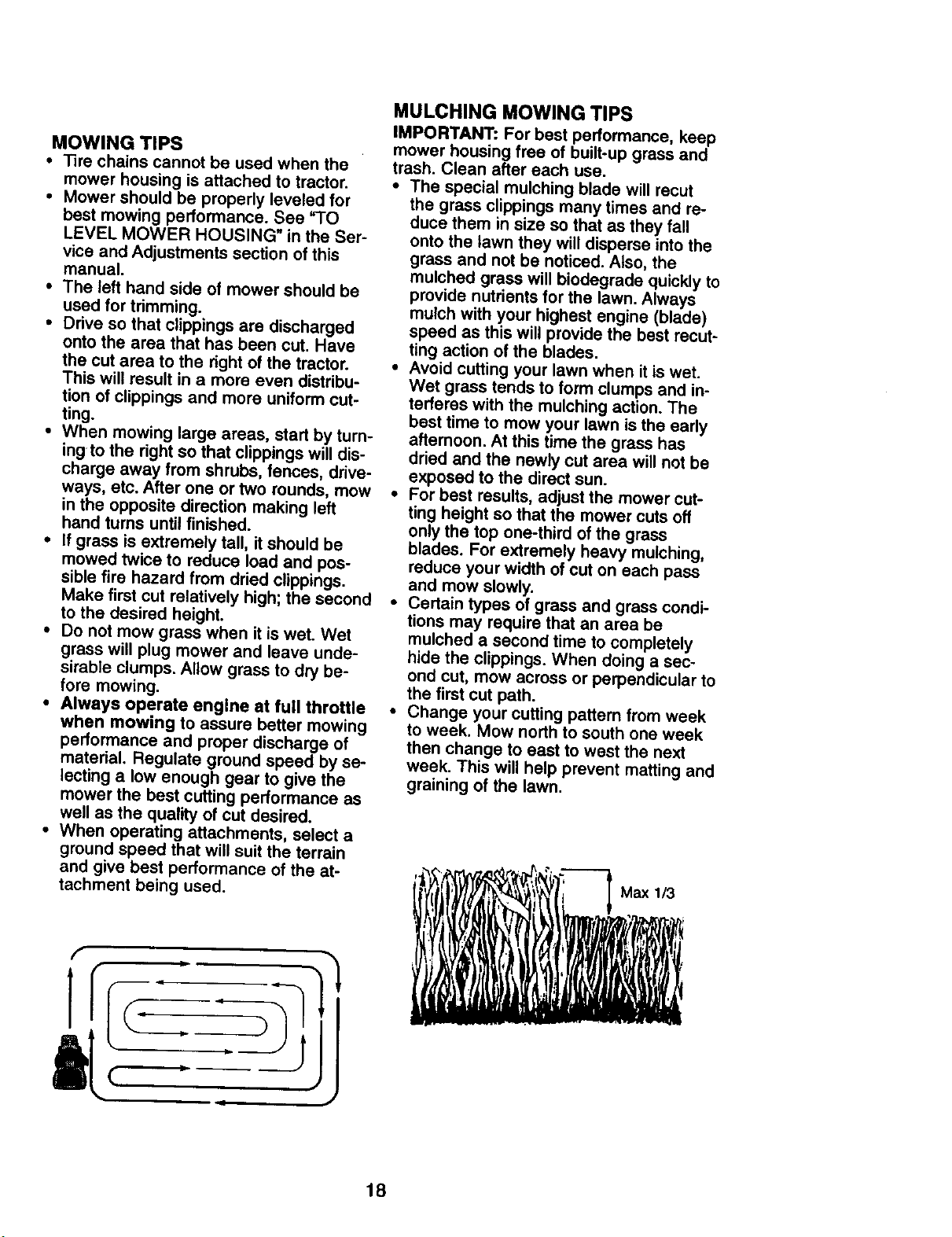
MOWING TIPS
• Tire chains cannot be used when the
mower housing is attached to tractor.
• Mower should be properly leveled for
best mowing performance. See =TO
LEVEL MOWER HOUSING" in the Ser-
vice and Adjustments section of this
manual.
• The left hand side of mower should be
used for trimming.
• Drive so that clippings are discharged
onto the area that has been cut. Have
the cut area to the right of the tractor.
This will result in a more even distribu-
tion of clippings and more uniform cut-
ting.
• When mowing large areas, start by turn-
ing to the right so that clippings will dis-
charge away from shrubs, fences, drive-
ways, etc. After one or two rounds, mow
in the opposite direction making left
hand turns until finished.
• If grass is extremely tall, it should be
mowed twice to reduce load and pos-
sible fire hazard from dried clippings.
Make first cut relatively high; the second
to the desired height.
• Do not mow grass when it is wet. Wet
grass will plug mower and leave unde-
sirable clumps. Allow grass to dry be-
fore mowing.
• Always operate engine at full throttle
when mowing to assure better mowing
performance and proper discharge of
material. Regulate ground speed by se-
lecting a low enough gear to give the
mower the best cutting performance as
well as the quality of cut desired.
• When operating attachments, select a
ground speed that will suit the terrain
and give best performance of the at-
tachment being used.
f
t
t
i
MULCHING MOWING TIPS
IMPORTANT: For best performance, keep
mower housing free of built-up grass and
trash. Clean after each use.
• The special mulching blade will recut
the grass clippings many times and re-
duce them in size so that as they fall
onto the lawn they will disperse into the
grass and not be noticed. A|so, the
mulched grass will biodegrade quickly to
provide nutrients for the lawn. Always
mulch with your highest engine (blade)
speed as this will provide the best recut-
ting action of the blades.
• Avoid cutting your lawn when it is wet.
Wet grass tends to form clumps and in-
terferas with the mulching action. The
best time to mow your lawn is the early
afternoon. At this time the grass has
dried and the newly cut area will not be
exposed to the direct sun.
• For best results, adjust the mower cut-
ting height so that the mower cuts off
only the top one-third of the grass
blades. For extremely heavy mulching,
reduce your width of cut on each pass
and mow slowly.
• Certain types of grass and grass condi-
tions may require that an area be
mulched a second time to completely
hide the clippings. When doing a sec-
ond cut, mow across or perpendicular to
the first cut path.
• Change your cutting pattern from week
to week. Mow north to south one week
then change to east to west the next
week. This will help prevent matting and
graining of the lawn.
18
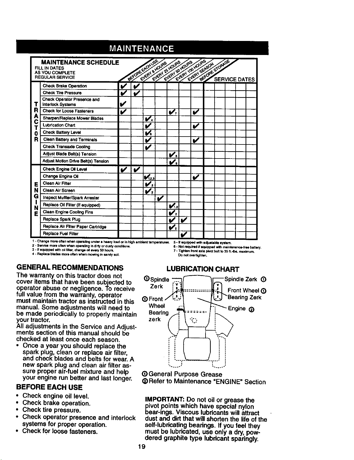
MAINTENANCE SCHEDULE __J'_ __D
FILL IN DATES _li_._//_._X'O_/,_/_'/_/_J '
AS YOU COMPLETE _' _'_ _"_Y _'_ _
REGULAR SERVICE ____'_ ATES
Check BrakeOperation
Check"11rePressure _1_/ _
Check OperatorPresence and
T InterlockSystems
Checkfor LooseFasteners V'7 I_
A SharpeNFlep;ace Mower Blades !
v',
,_,=c. "T Check Battery Level
R Clean BatteryandTerminals !V' V'
CheckTransaxleCooling
AdjustBlade Belt(s)Tension I_s
v,
Adjust Motion Ddve Belt(s) Tension
Check EngineOil Level _
Change EngineOil _,: I_
E Clean AirFilter _:
N Clean AirScreen
i Inspect Muffler/SparkArrester I_
EN Replace Oil Filter (If equipped) _1.1
Clean EngineCoolingRns
i/,
Replace Spark Rug
v',ReplaceAir Rlter Paper Cartridge
Replace Fuel Filter
I -Cha_gemo_ollenwheflopefa#ngunderahuwIo&dotlnhighamb4enttom_m_r_" 5-1fequippedwi61sdjuztaMesystem.
2 - Sewk_ more often when opera,rig tn dlrly or dusty ¢ondilk)r_. 6 - Not required if equipped with rnlir)lenarJce-frN bartok/.
3 - If equipped with oH fiAe_,charge Oll ever/50 hours. 7 - Tighten front axll pivot boltto 35 fl.*lbs, max_um.
4 - Replace blldes morl oltln when mowing in sandy s_l. Do not overUghten.
GENERAL RECOMMENDATIONS
The warranty on this tractor does not
cover items that have been subjected to
operator abuse or negligence. To receive
full value from the warranty, operator
must maintain tractor as instructed in this
manual. Some adjustments will need to
be made periodically to properly maintain
YAOUrtractor.
II adjustments in the Service and Adjust-
ments section of this manual should be
checked at least once each season.
• Once a year you should replace the
spark plug, clean or replace air filter,
and check blades and belts for wear. A
new spark plug and clean air filter as-
sure proper air-fuel mixture and help
your engine run better and last longer.
BEFORE EACH USE
• Check engine oil level.
• Check brake operation.
• Check tire pressure.
• Check operator presence and interlock
systems for proper operation.
• Check for loose fasteners.
LUBRICATION CHART
(1)Spindle
Zerk !__:_
(_ Front/_i.
Wl_eel ..c.
Bearings,_
zerk
_General Purpose Grease
_)Refer to Maintenance "ENGINE" Section
IMPORTANT: Do not oil or grease the
_ivot points which have special nylon
ear-ings. Viscous lubricants will attract
dust and dirt that will shorten the life of the
self-lubricating bearings. If you feel they
must be lubricated, use only a dry, pow-
dered graphite type lubricant sparingly.
19
TRACTOR
Always observe safety rules when per-
forming any maintenance.
BRAKE OPERATION
If tractor requires more than six (6) feet
stopping distance at high speed in high-
est gear, then brake must be adjusted.
(See "TO ADJUST BRAKE" in the Service
and Adjustments section of this manual).
TIRES
• Maintain proper airpressure in all tires
(See "PRODUCT SPECIFICATIONS"
section of this manual).
• Keep tires free of gasoline, oil, or insect
control chemicals which can harm rub-
ber.
• Avoid stumps, stones,deep ruts,sharp
objects and other hazards that may
cause tire damage.
NOTE: To seal tire punctures and prevent
flat tires due to slow leaks, tire sealant
may be purchased from your local parts
dealer. Tire sealant also prevents tire dry
rot and corrosion.
OPERATOR PRESENCE SYSTEM
Be sure that operator presence and inter-
lock systems are working properly. If your
tractor does not function as described be-
low, repair the problem immediately.
• The engine should not start unless the
clutch/brake pedal is fully depressed
and attachment clutch control is in the
disengaged position.
• When the engine is running, any at-
tempt by the operator to leave the seat
without first setting the parking brake
should shut off the engine.
i When the engine is running and the at-
tachment clutch is engaged, any at-
tempt by the operator to leave the seat
should shut offthe engine.
The attachment clutch should never op-
erate unless the operator is in the seat.
BLADE CARE
For best results mower blades must be
kept sharp. Replace bent or damaged
blades.
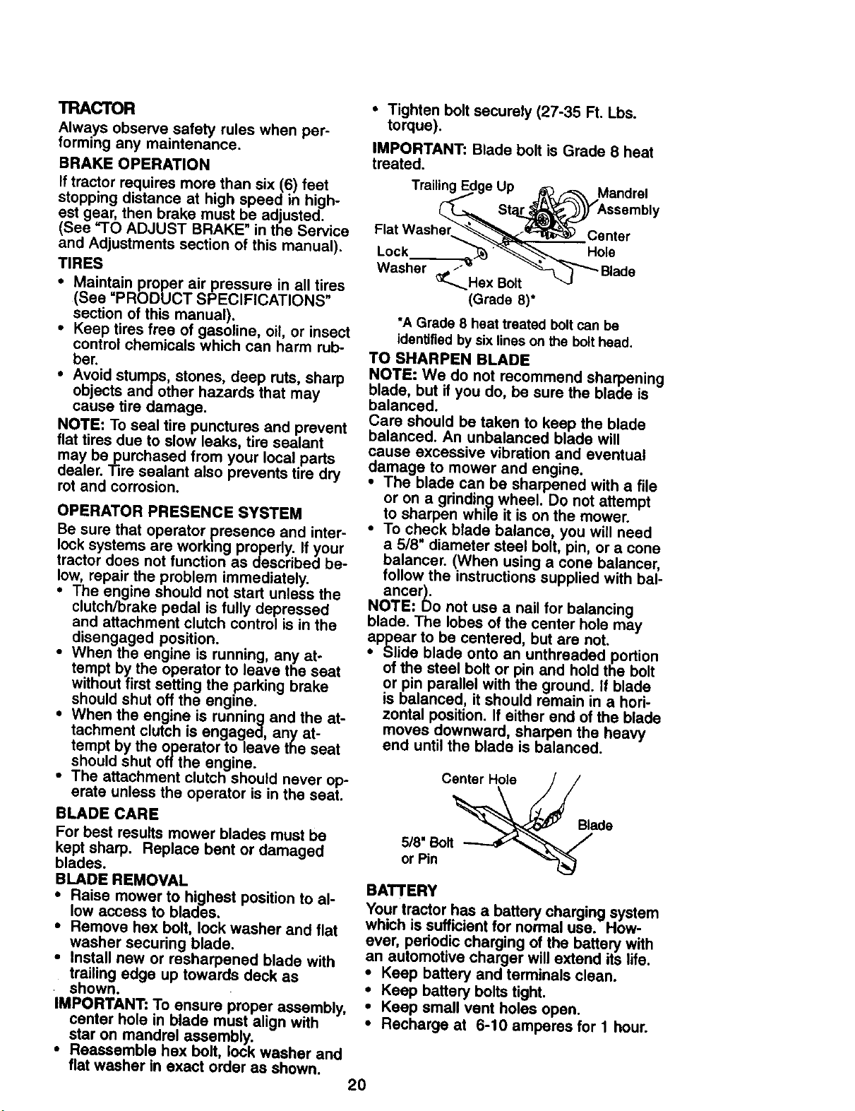
BLADE REMOVAL
• Raise mower to highest position to al-
low access to blades.
• Remove hex bolt, lock washer and flat
washer securing blade.
• Install new or resharpened blade with
trailing edge up towards deck as
shown.
IMPORTANT: To ensure proper assembly,
center hole in blade must align with
star on mandrel assembly.
• Reassemble hex bolt, lock washer and
flat washer in exact order as shown.
• Tighten bolt securely (27-35 Ft. Lbs.
torque).
IMPORTANT: Blade bolt is Grade 8 heat
treated.
Trailing E Mandrel
Lock
Washer
Center
Hole
"A Grade 8 heat treated boltcan be
identified by six lines on the bolthead.
TO SHARPEN BLADE
NOTE: We do not recommend sharpening
blade, but if you do, be sure the blade is
balanced.
Care should be taken to keep the blade
balanced, An unbalanced blade will
cause excessive vibration and eventual
damage to mower and engine.
• The blade can be sharpened with a file
or on a grinding wheel. Do not attempt
to sharpen while it is on the mower.
• To check blade balance, you will need
a 5/8" diameter steel bolt, pin, or a cone
balancer. (When using a cone baiancer,
follow the instructions supplied with bal-
ancer).
NOTE: Do not use a nail for balancing
blade. The lobes of the center hole may
appear to be centered, but are not.
• Slide blade onto an unthreaded portion
of the steel bolt or pin and hold the bolt
or pin parallel with the ground. If blade
is balanced, it should remain in a hori-
zontal position. If either end of the blade
moves downward, sharpen the heavy
end until the blade is balanced.
Center Hole
5/8" Bolt
or Pin
Blade
BATTERY
Your tractor has a battery charging system
which is sufficient for normal use. How-
ever, periodic charging of the battery with
an automotive charger will extend its life.
• Keep battery and terminals clean.
• Keep battery bolts tight.
• Keep small vent holes open.
• Recharge at 6-10 amperes for 1 hour.
2O
TO CLEAN BATTERY AND TERMINALS
Corrosion and dirt on the battery and ter-
minals can cause the battery to "leak"
power.
• Remove terminal guard.
• Disconnect BLACK battery cable first
then RED battery cable and remove
battery from tractor.
• Rinse the battery with plain water and
dry.
• Clean terminals and battery cable ends
with wire brush until bright.
• Coat terminals with grease or petro-
leum jelly.
• Reinstall battery (See "REPLACING
BATTERY" in the SERVICE AND AD-
JUSTMENTS section of this manual),
V-BELTS
Check V-belts for deterioration and wear
after 100 hours of operation and replace if
necessary. The belts are not adjustable.
Replace belts if they begin to slip from
wear.
TRANSAXLE COOLING
The transmission fan and cooling fins
should be kept clean to assure proper
cooling.
Do not attempt to clean fan or transmis-
sion while engine is running or while the
transmission is hot.
• Inspect cooling fan to be sure fen
blades are intact and clean.
• Inspect cooling fins for dirt, grass clip
pings and other materials. To prevent
damage to seals, do not use com-
pressed air or high pressure sprayer to
clean cooling fins.
TRANSAXLE PUMP FLUID
The transaxle was sealed at the factory
and fluid maintenance is not required for
the life of the transaxle. Should the
transaxle ever leak or require servicing,
contact your nearest authorized service
center.
ENGINE
LUBRICATION
Only use high quality detergent oil rated
with API service classification SF, SG, or
SH. Select the oil's SAE viscosity grade
according to your expected operating
temperature.
TEMPERATURERANGEA
NOTE: Although multi-viscosity oils
(5W30, 10W30 etc.) improve starting in
cold weather, these multi-viscosity oils
will result in increased oil consumption
when used above 32°1=. Check your en-
gine oil level more frequently to avoid
possible engine damage from running
low on oil.
Change the oil after every 50 hours of op-
eration or at least once a year if the trac-
tor is not used for 50 hours in one year.
Check the crankcase oil level before
starting the engine and after each eight
(8) hours of operation. "13ghtenoil fill cap/
dipstick securely each time you check the
oil level.
TO CHANGE ENGINE OIL
Determine temperature range expected
before oil change. All oil must meet API
service classification SF, SG or SH.
• Be sure tractor is on level surface.
• Oil will drain more freely when warm.
• Catch oil in a suitable container.
• Remove oil fill cap/dipstick. Be careful
not to allow dirt to enter the engine
when changing oil.
• Remove drain plug.
• After oil has drained completely, re-
place oil drain plug and tighten se-
curely.
• Refill engine with oil through oil fill dip-
stick tube. Pour slowly. Do not overfill.
For approxlmete capacity see "PROD-
UCT SPECIFICATIONS" section of this
manual.
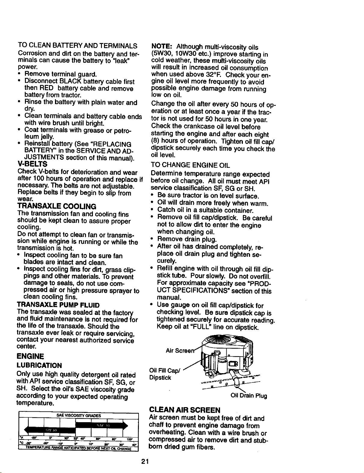
• Use gauge on oil fill cap/dipstick for
checking level. Be sure dipstick cap is
tightened securely for accurate reading.
Keep oil at "FULL" line on dipstick.
Air
Oil FillCap/
Dipstick
CLEAN AIR SCREEN
Air screen must be kept free of dirt and
chaff to prevent engine damage from
overheating. Clean with a wire brush or
compressed air to remove dirt and stub-
born dried gum fibers.
21
CLEAN AIR INTAKE/COOLING AREAS
To insure proper cooling, make sure the
grass screen, cooling fins, and other ex-
ternal surfaces of the engine are kept
clean at all times.
Evew 100 hours of operation (more often
under extremely dusty, dirty conditions),
remove the blower housing and other
cooling shrouds. Clean the cooling fins
and external surfaces as necessary. Make
sure the cooling shrouds are reinstalled.
NOTE: Operating the engine with a
blocked grass screen, dirty or plugged
cooling fins, and/or cooling shrouds re-
moved will cause engine damage due to
overheating.
ENGINE OIL FILTER
Replace the engine oil filter every season
or every other oil change if the tractor is
used more than 100 hours in one year.
• Unscrew old filter by turning counter-
clockwise. Use a suitable container to
catch oil.
• Apply a thin coating of new engine oil to
rubber gasket on replacement oil filter.
• Install replacement oil filter by turning
clockwise until rubber gasket contacts
mounting surface, then tighten filter an
additional 1/2 to 3/4 turn.
• Fill crankcase with new oil (See "TO
CHANGE ENGINE OIL" in this section of
this manual). For approximate capacity
see =PRODUCT SPECIFICATIONS"
section of this manual.
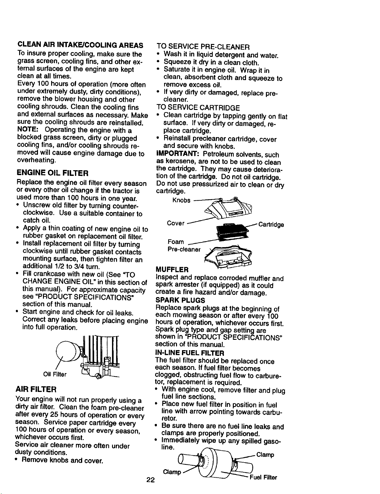
• Start engine and check for oil leaks.
Correct any leaks before placing engine
into full operation.
Oil Filter
AIR FILTER
Your engine will not run properly using a
dirty air filter. Clean the foam pre-cleaner
after every 25 hours of operation or every
season. Service paper cartridge every
100 hours of operation or every season,
whichever occurs first.
Service air cleaner more often under
dusty conditions.
• Remove knobs and cover.
TO SERVICE PRE-CLEANER
• Wash it in liquid detergent and water.
• Squeeze it dry in a clean cloth.
• Saturate it in engine oil. Wrap it in
clean, absorbent cloth and squeeze to
remove excess oil.
• If very dirty or damaged, replace pre-
cleaner.
TO SERVICE CARTRIDGE
• Clean cartridge by tapping gently on flat
surface. If very dirty or damaged, re-
place cartridge.
• Reinstall precleaner cartridge, cover
and secure with knobs.
IMPORTANT: Petroleum solvents, such
as kerosene, are not to be used to clean
the cartddge. They may cause deteriora-
tion of the cartridge. Do not oil cartridge.
Do not use pressurized air to clean or dry
cartridge.
Foam
Pre-cleener
MUFFLER
Inspect and replace corroded muffler and
spark arrester (if equipped) as it could
create a fire hazard and/or damage.
SPARK PLUGS
Replace spark plugs at the beginning of
each mowing season or after every 100
hours of operation, whichever occurs first.
Spark plug type and gap setting are
shown in "PRODUCT SPECIFICATIONS"
section of this manual.
IN-LINE FUEL FILTER
The fuel filter should be replaced once
each season. If fuel filter becomes
clogged, obstructing fuel flow to carbure-
tor, replacement is required.
• With engine cool, remove filter and plug
fuel line sections:
• Place new fuel filter in position in fuel
line with arrow pointing towards carbu-
retor.
• Be sure there are no fuel line leaks and
clamps are properly positioned.
• Immediately wipe up any spilled gaso-
line. _ Clamp
Clamp / _-_--_"'_-"Fuel Filter
22
CLEANING
• Clean engine, battery, seat, finish, etc.
of all foreign matter.
• Keep finished surfaces and wheels free
of all gasoline, oil, etc.
• Protect painted surfaces with automo-
tive type wax.
We do not recommend using a garden
hose to clean your tractor unless the elec-
trical system, muffler, air filter and carbure-
tor are covered to keep water out. Water in
engine can result in a shortened engine
life.
,A CAUTION: Before performing any service or adjustments:
• Depress clutch/brake pedal fully and set parking brake.
• Place motion control lever in neutral (N) position.
• Place attachment clutch in "DISENGAGED" position.
• Turn ignition key =OFI_ and remove key.
• Make sure the blades and all moving parts have completely stopped.
• Disconnect spark plug wire from spark plug and place wire where it cannot come
in contact with plug.
"tRACTOR
TO REMOVE MOWER
• Place attachment clutch in "DISEN-
GAGED" position.
• Turn height adjustment knob to lowest
setting.
• Lower mower to its lowest position.
• Remove retainer spring holding anti-
swaybar to chassis bracket and disen-
gage anti-swaybar from bracket.
• Remove retainer springs from suspen-
sion arms at deck and disengage arms
from deck.
• Raise attachment lift to its highest posi-
tion.
uft
Adjustment Nuts Links
Suspension Arms
Chassis
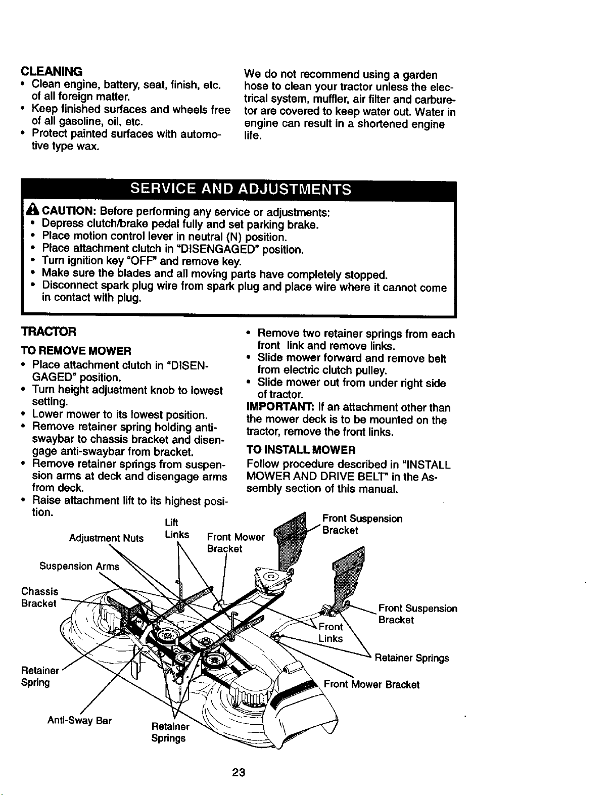
• Remove two retainer springs from each
front link and remove links.
• Slide mower forward and remove belt
from electric clutch pulley.
• Slide mower out from under right side
of tractor.
IMPORTANT: If an attachment other than
the mower deck is to be mounted on the
tractor, remove the front links.
TO INSTALL MOWER
Follow procedure described in =INSTALL
MOWER AND DRIVE BELl-" in the As-
sembly section of this manual.
Front Mower
Bracket
Front Suspension
Front Suspension
Bracket
Retaine
Spring
Retainer Springs
Front Mower Bracket
Anti-Sway Bar
Retainer
Springs
23
TO LEVEL MOWER HOUSING
Adjust the mower white tractor is parked
on level ground or driveway. Make sure
tires are properly inflated (See =PROD-
UCT SPECIFICATIONS"). If tires are over
or underinflated, you will not properly ad-
just your mower.
SIDE-TO-SIDE ADJUSTMENT
• Raise mower to its highest position.
• At the midpoint of both sides of mower,
measure height from bottom edge of
mower to ground. Distance "A" on both
sides of mower should be the same or
within 1/4" of each other.
• If adjustment is necessary, make adjust-
ment on one side of mower only.
• To raise one side of mower, tighten lift
link adjustment nut on that side.
• To lower one side of mower, loosen lift
link adjustment nut on that side.
NOTE: Each full turn of adjustment nut
will change mower height about 1/8".
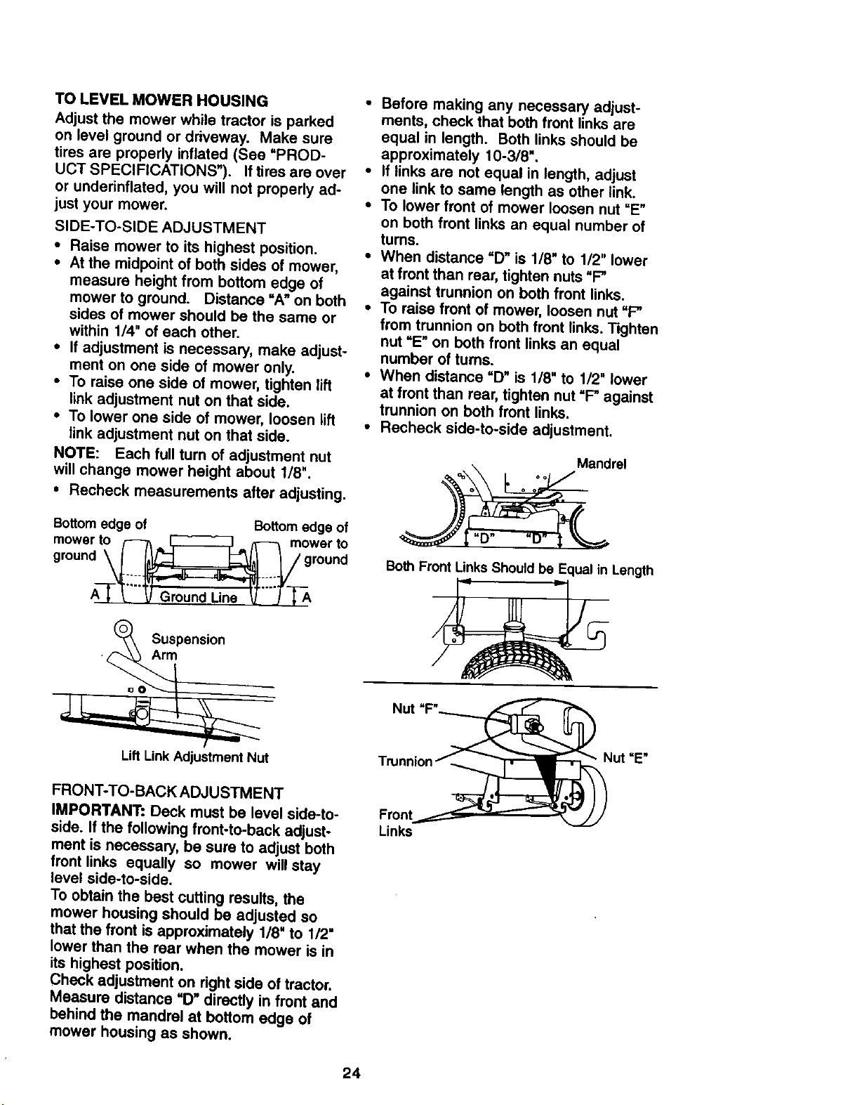
• Recheck measurements after adjusting.
Bottomedge of Bottom edge of
mower to _ = _, _ mower to
0,oun° _ p,roon0
A-I- J arou -J T-A
(_ Suspension
Lift Link Adjustment Nut
• Before making any necessary adjust-
ments, check that both front links are
equal in length. Both links should be
approximately 10-3/8".
• If links are not equal in length, adjust
one link to same length as other link.
• To lower front of mower loosen nut =E"
on both front links an equal number of
turns.
• When distance =D" is 1/8" to 1/2" lower
at front than rear, tighten nuts "F"
against trunnion on both front links.
• To raise front of mower, loosen nut "F"
from trunnion on both front links. Tighten
nut =E" on both front links an equal
number of turns.
• When distance "D" is 1/8" to 1/2" lower
at front than rear, tighten nut "F" against
trunnion on both front links.
• Recheck side-to-side adjustment.
Mandrel
oo oo
o o o
Both Front Links Should be Equal in Length
Trunnion
Nut "E"
FRONT-TO-BACK ADJUSTMENT
IMPORTANT: Deck must be level side-to-
side. If the following front-to-back adjust-
ment is necessary, be sure to adjust both
front links equally so mower will stay
level side-to-side.
To obtain the best cutting results, the
mower housing should be adjusted so
that the front is approximately 1/8" to 1/2"
lower than the rear when the mower is in
its highest position.
Check adjustment on right side of tractor.
Measure distance "D" directly in front and
behind the mandrel at bottom edge of
mower housing as shown.
Front
Links
24
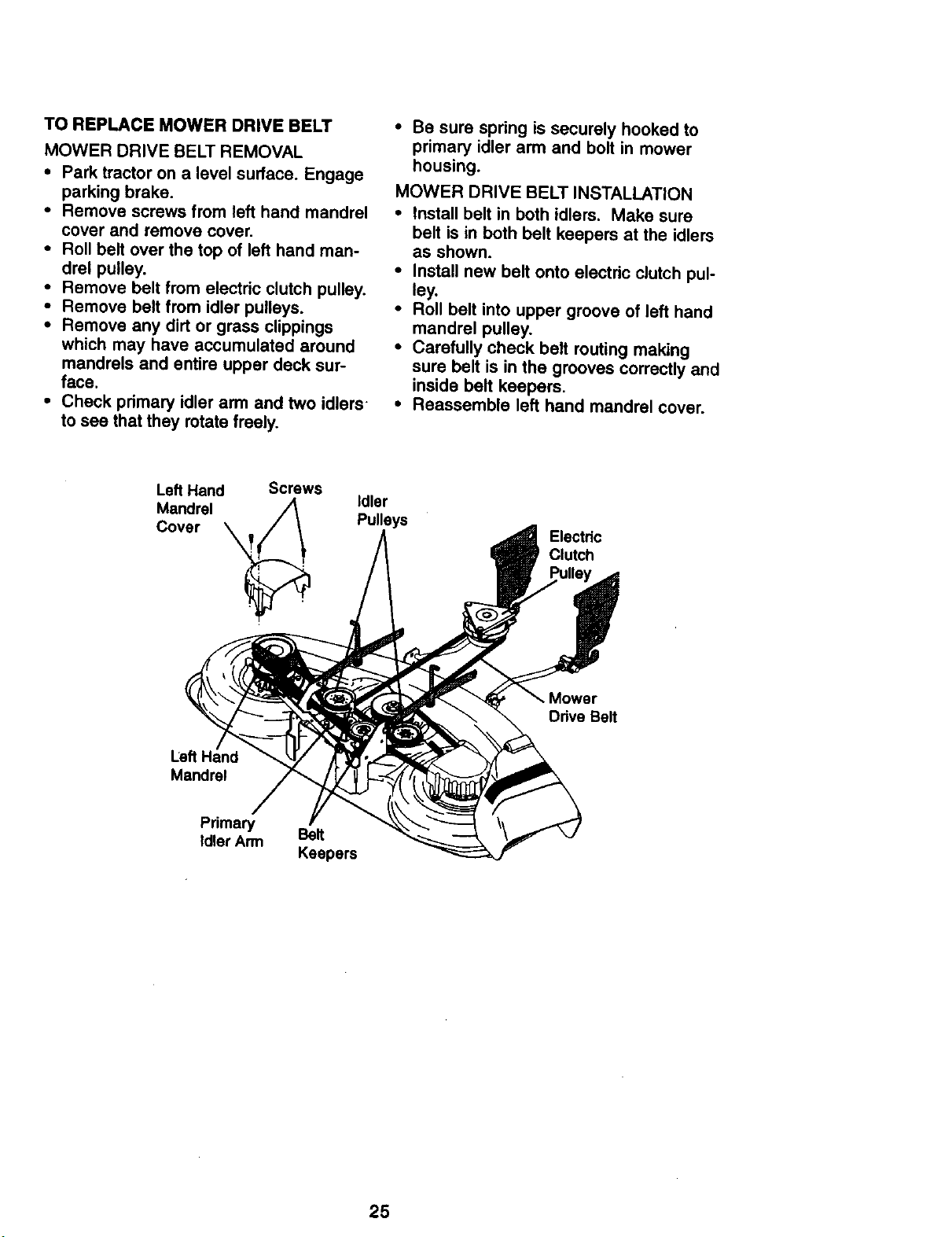
TO REPLACE MOWER DRIVE BELT
MOWER DRIVE BELT REMOVAL
• Park tractor on a level surface. Engage
parking brake.
• Remove screws from left hand mandrel
cover and remove cover.
• Roll belt over the top of left hand man-
drel pulley.
• Remove belt from electric clutch pulley.
• Remove belt from idler pulleys.
• Remove any dirtor grass clippings
which may have accumulated around
mandrels and entire upper deck sur-
face.
• Check primary idler arm and two idlers
to see that they rotate freely.
• Be sure spring is securely hooked to
primary idler arm and bolt in mower
housing.
MOWER DRIVE BELT INSTALLATION
• Install belt in both idlers. Make sure
belt is in both belt keepers at the idlers
as shown.
• Install new belt onto electric clutch pul-
ley,
• Roll belt into upper groove of left hand
mandrel pulley.
• Carefully check belt routing making
sure belt is in the grooves correctly and
inside belt keepers.
• Reassemble lefthand mandrel cover.
Left Hand Screws
Mandrel _
Cover
Idler
Pulleys
Electdc
Clutch
Mower
Drive Belt
Left Hand
Mandrel
Primary Belt
Idler Arm
Keepers
25
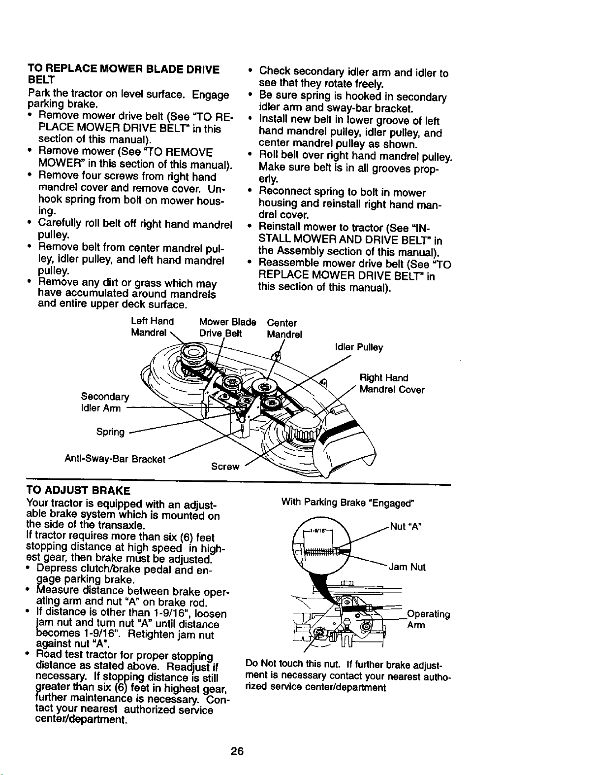
TO REPLACE MOWER BLADE DRIVE
BELT
Park the tractor on level surface. Engage
parking brake,
• Remove mower drive belt (See "TO RE-
PLACE MOWER DRIVE BELT" in this
section of this manual).
• Remove mower (See "TO REMOVE
MOWER" in this section of this manual).
• Remove four screws from right hand
mandrel cover and remove cover. Un-
hook spring from bolt on mower hous-
ing.
• Carefully roll belt off right hand mandrel
pulley.
• Remove belt from center mandrel pul-
ley, idler pulley, and left hand mandrel
pulley.
• Remove any dirt or grass which may
have accumulated around mandrels
and entire upper deck surface.
• Check secondary idler arm and idler to
see that they rotate freely.
• Be sure spring is hooked in secondary
idler arm and sway-bar bracket.
• Install new belt in lower groove of left
hand mandrel pulley, idler pulley, and
center mandrel pulley as shown.
• Roll belt over right hand mandrel pulley.
Make sure belt is in all grooves prop-
erly.
• Reconnect spring to bolt in mower
housing and reinstall right hand man-
drel cover.
• Reinstall mower to tractor (See "IN-
STALL MOWER AND DRIVE BELT" in
the Assembly section of this manual).
• Reassemble mower drive belt (See "TO
REPLACE MOWER DRIVE BELT" in
this section of this manual).
Left Hand Mower Blade Center
Ddva Belt Mandrel
Idler Pulley
Secondary
Idler Arm
Spring
Right Hand
Anti-Sway-Bar Bracket
Screw
TO ADJUST BRAKE
Your tractor is equipped with an adjust-
able brake system which is mounted on
the side of the transaxle.
If tractor requires more than six (6) feet
stopping distance at high speed in high-
est gear, then brake must be adjusted.
° Depress clutch/brake pedal and en-
gage parking brake.
• Measure distance between brake oper-
ating arm and nut "A" on brake rod.
• If distance is other than 1-9/16", loosen
jam nut and turn nut "A" until distance
becomes 1-9/16". Retighten jam nut
against nut "A'.
• Road test tractor for proper stopping
distance as stated above. Readjust if
necessary. If stopping distance =sstill
greater than six (6) feet in highest gear,
further maintenance is necessary. Con-
tact your nearest authorized service
center/department.
With Parking Brake "Engaged"
=A"
Jam Nut
Arm
Do Not touch this nut. If further brake adjust-
ment is necessary contact your nearest autho-
rized service center/department
26
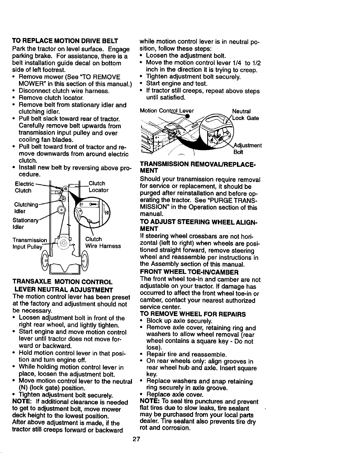
TO REPLACE MOTION DRIVE BELT
Park the tractor on level surface. Engage
parking brake. For assistance, there is a
belt installation guide decal on bottom
side of left footrest.
• Remove mower (See'TO REMOVE
MOWER" in this section of this manual.)
• Disconnect clutch wire harness.
• Remove clutch locator.
• Remove belt from stationary idler and
clutching idler.
• Pull belt slack toward rear of tractor.
Carefully remove belt upwards from
transmission input pulley and over
cooling fan blades.
• Pull belt toward front of tractor and re-
move downwards from around electric
clutch.
• Install new belt by reversing above pro-
cedure.
Electric
Clutch
Clutching-""
Idler
Stationary j
Idler
Transmission
Input PulleyS__=
Clutch
Locater
II-_i_::_ii!_ ClutCharness
TRANSAXLE MOTION CONTROL
LEVER NEUTRAL ADJUSTMENT
The motion control lever has been preset
at the factory and adjustment should not
be necessary.
• Loosen adjustment bolt in front of the
right rear wheel, and lightly tighten.
• Start engine and move motion control
lever until tractor does not move for-
ward or backward.
• Hold motion control lever in that posi-
tion and turn engine off.
• While holding motion control lever in
place, loosen the adjustment bolt.
• Move motion control lever to the neutral
(N) (lock gate) position.
• Tighten adjustment bolt securely.
NOTE: If additional clearance is needed
to get to adjustment bolt, move mower
deck height to the lowest position.
After above adjustment is made, if the
tractor still creeps forward or backward
while motion control lever is inneutral po-
sition, follow these steps:
• Loosen the adjustment bolt.
• Move the motion control lever 1/4 to 1/2
inch in the direction it is trying to creep.
• Tighten adjustment bolt securely.
• Start engine and test.
• If tractor still creeps, repeat above steps
until satisfied.
Motion Neutral
Gate
Bolt
TRANSMISSION REMOVAUREPLACE-
MENT
Should your transmission require removal
for service or replacement, it should be
purged after reinstallation and before op-
erating the tractor. See =PURGE TRANS-
MISSION" in the Operation section of this
manual.
TO ADJUST STEERING WHEEL ALIGN-
MENT
If steering wheel crossbars are not hori-
zontal (left to right) when wheels are posi-
tioned straight forward, remove steering
wheel and reassemble per instructions in
the Assembly section of this manual.
FRONT WHEEL TOE-IN/CAMBER
The front wheel toe-in and camber are not
adjustable on your tractor. If damage has
occurred to affect the front wheel toe-in or
camber, contact your nearest authorized
service center.
TO REMOVE WHEEL FOR REPAIRS
• Block up axle securely.
• Remove axle cover, retaining ring and
washers to allow wheel removal (rear
wheel contains a square key - Do not
lose).
• Repair tire and reassemble.
• On rear wheels only: align grooves in
rear wheel hub and axle. Insert square
key.
• Replace washers and snap retaining
ring securely in axle groove.
• Replace axle cover.
NOTE: To seal tire punctures and prevent
flat tires due to slow leaks, tire sealant
may be purchased from your local parts
dealer. Tire sealant also prevents tire dry
rot and corrosion.
27
Washers
Retaining _ fBrf_
Ring
Axle/Cover "_Squara Key
(Rear Wheel Only)
TO START ENGINE THAT HAS A WEAK
BATTERY
CAUTION: Lead-acid batteries gener-
ate explosive gases. Keep sparks, flame
and smoking materials away from batter-
ies. Always wear eye protection when
around batteries.
If your battery is too weak to start the en-
gine, it should be recharged. (See "BAT-
TERY" in the MAINTENANCE section of
this manual).
If "jumper cables" are used for emergency
starting, follow this procedure:
IMPORTANT: Your tractor Is equiped with
a 12 volt negative grounded system. The
other vehical must also be a 12 volt nega-
tive grounded system. Do not use your
tractor battery to start other vehicles.
TO ATTACH JUMPER CABLES -
• Connect each end of the RED cable to
the POSITIVE (+) terminal of each bat-
tery, taking care not to short against
chassis.
• Connect one end of the BLACK cable
to the NEGATIVE (-) terminal of fully
charged battery.
• Connect the other end of the BLACK
cable to good CHASSIS GROUND,
away from fuel tank and battery.
TO REMOVE CABLES, REVERSE OR-
DER -
• BLACK cable first from chassis and
then from the fully charged battery.
• RED cable last from both batteries.
"Positive" (+)_ "Negative"
L.H. Panel
(-)
REPLACING BATrERY
CAUTION: Do not short battery termi-
nals by allowing a wrench or any other
object to contact both terminals at the
same time. Before connecting battery, re-
move metal bracelets, wristwatch
bands,rings,etc.
Positive terminal must be connected first
to prevent sparking from accidental
grounding.
• Uft hood to raised position.
: Remove terminal guard.
Disconnect BLACK battery cable then
RED battery cable and carefully remove
battery from tractor.
• Install new battery with terminals in
same position as old battery.
: Reinstall terminal guard.
First connect REDbattery cable to posi-
tive (+) battery terminal with hex bolt
and keps nut as shown. Tighten se-
curely.
• Connect BLACK grounding cable to
negative (-) battery terminal with re-
mainin_ hex bolt and keps nut. Tighten
securely
• Close terminal access doors.
• Close hood.
Terminal keps Nut
Access
Door
Hex Bolt
Positive
Cable
Guard
(Black) Cable
TO REPLACE HEADLIGHT BULB
• Raise hood.
• Pull bulb holder out of the hole in the
backside of the grill.
• Replace bulb in holder and push bulb
holder securely back into the hole in the
backside of the grill.
• Close hood.
28
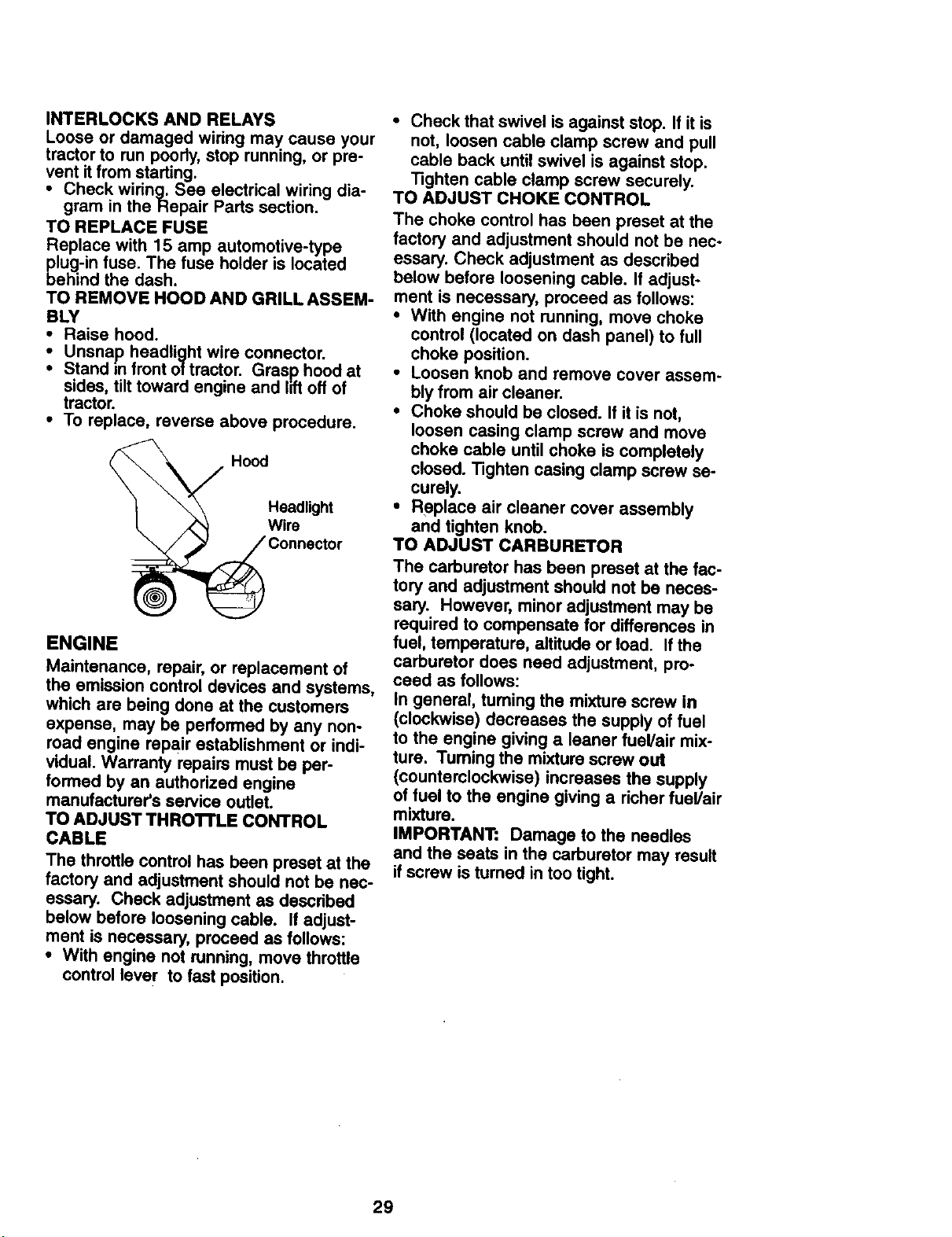
INTERLOCKSANDRELAYS
Loose or damaged wiring may cause your
tractor to run poody, stop running, or pre-
vent it from starting.
• Check wiring. See electrical wiring dia-
gram in the Repair Parts section.
TO REPLACE FUSE
Replace with 15 amp automotive-type
plug-in fuse. The fuse holder is located
behind the dash,
TO REMOVE HOOD AND GRILL ASSEM-
BLY
• Raise hood.
Unsnap headlight wire connector.
: Stand in front of tractor. Grasp hood at
sides, tilttoward engine and liftoff of
tractor.
• To replace, reverse above procedure.
Hood
Headlight
Wire
ENGINE
Maintenance, repair, or replacement of
the emission control devices and systems,
which are being done at the customers
expense, may be performed by any non-
read engine repair establishment or indi-
vidual. Warranty repairs must be per-
formed by an authorized engine
manufacturer's service outlet.
TO ADJUST THROTTLE CONTROL
CABLE
The throttle control has been preset at the
factory and adjustment should not be nec-
essary. Check adjustment as described
below before loosening cable. If adjust-
ment is necessary, proceed as follows:
• With engine not running, move throttle
control lever to fast position.
• Check that swivel is against stop. If it is
not, loosen cable clamp screw and pull
cable back untilswivel is against stop.
Tighten cable clamp screw securely.
TO ADJUST CHOKE CONTROL
The choke control has been preset at the
factory and adjustment should not be nec-
essary. Check adjustment as described
below before loosening cable. If adjust-
ment is necessary, proceed as follows:
• With engine not running, move choke
control (located on dash panel) to full
choke position.
• Loosen knob and remove cover assem-
bly from air cleaner.
• Choke should be closed. If it is not,
loosen casing clamp screw and move
choke cable until choke is completely
closed. Tighten casing clamp screw se-
curely.
• Replace air cleaner cover assembly
and tighten knob.
TO ADJUST CARBURETOR
The carburetor has been preset at the fac-
tory and adjustment should not be neces-
sary. However, minor adjustment may be
required to compensate for differences in
fuel, temperature, altitude or load. Ifthe
carburetor does need adjustment, pro-
ceed as follows:
In general, turning the mixture screw in
(clockwise) decreases the supply of fuel
to the engine giving a leaner fuel/air mix-
ture. Tuming the mixture screw out
(counterclockwise) increases the supply
of fuel to the engine giving a richer fuel/air
mixture.
IMPORTANT: Damage to the needles
and the seats in the carburetor may result
ifscrew is turned in too tight.
29
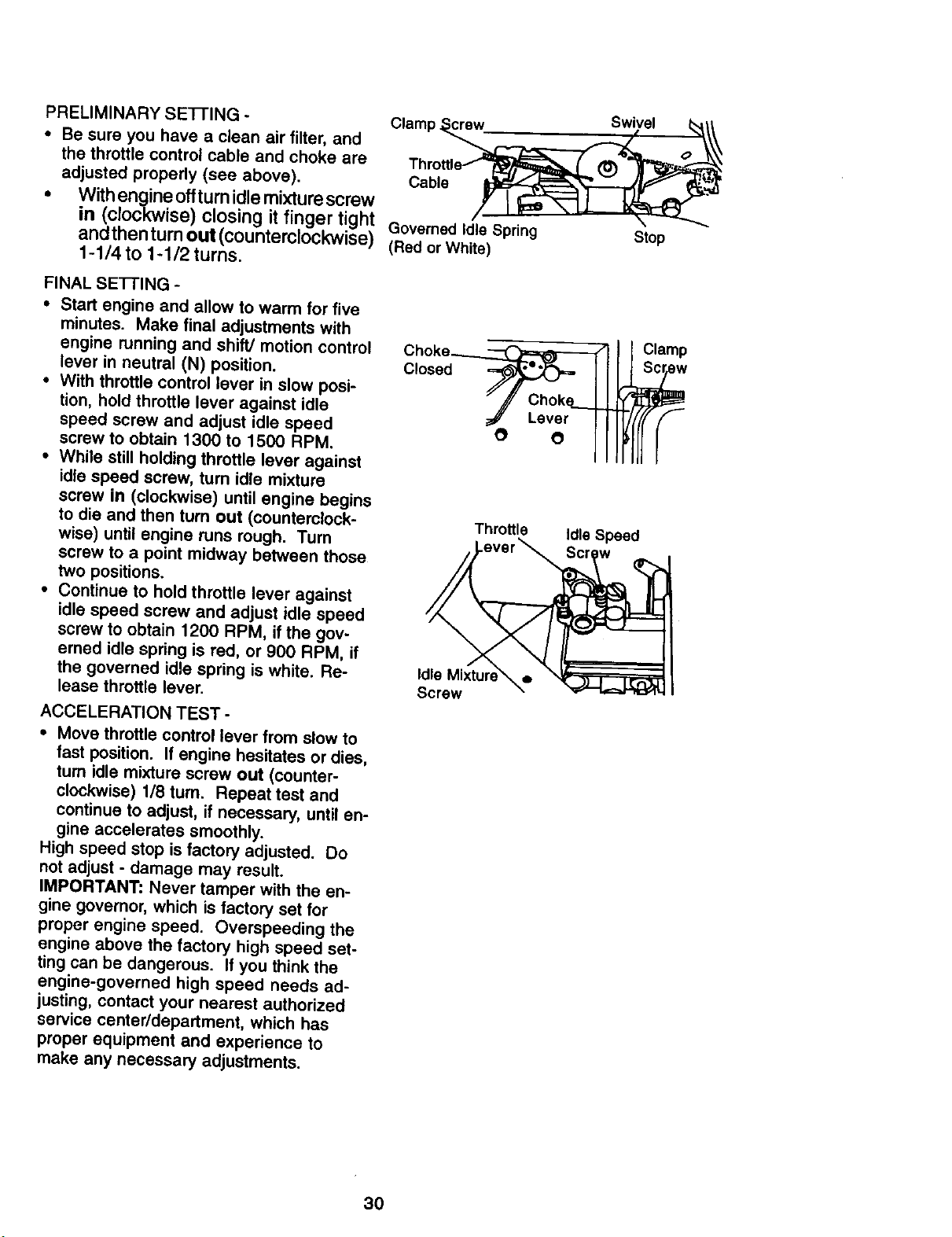
PRELIMINARY SE-I-FING -
• Be sure you have a clean air filter, and
the throttle control cable and choke are
adjusted properly (see above). Cable
• Withengineoffturnidlemixturescrew
in (clockwise) closing it finger tight
andthenturnout (counterclockwise) Governed Idle Spring
1-1/4 to 1-1/2 turns. (Red or White)
FINAL SEI-I'ING -
• Start engine and allow to warm for five
minutes. Make final adjustments with
engine running and shift/motion control
lever in neutral (N) position.
• With throttle control lever in slow posi-
tion, hold throttle lever against idle
speed screw and adjust idle speed
screw to obtain 1300 to 1500 RPM.
• While still holding throttle lever against
idle speed screw, turn idle mixture
screw in (clockwise) until engine begins
to die and then turn out (countemlock-
wise) until engine runs rough. Turn
screw to a point midway between those
two positions.
• Continue to hold throttle lever against
idle speed screw and adjust idle speed
screw to obtain 1200 RPM, if the gov-
erned idle spring is red, or 900 RPM, if
the governed idle spring is white. Re-
lease throttle lever.
ACCELERATION TEST -
• Move throttle control lever from slow to
fast position. If engine hesitates or dies,
turn idle mixture screw out (counter-
clockwise) 1/8 turn. Repeat test and
continue to adjust, if necessary, until en-
gine accelerates smoothly.
High speed stop is factory adjusted. Do
not adjust - damage may result.
IMPORTANT: Never tamper with the en-
gine governor, which is factory set for
proper engine speed. Overspeeding the
engine above the factory high speed set-
ting can be dangerous. If you think the
engine-governed high speed needs ad-
justing, contact your nearest authorized
service center/department, which has
proper equipment and experience to
make any necessary adjustments.
Choke_
Closed _ I
" _' ChokL
_#" Lever
O O
Throttle
Screw
Swivel
Stop
Clamp
Idle Speed
30
Immediately prepare your tractor for stor-
age at the end of the season or if the trac-
tor will not be used for 30 days or more.
CAUTION: Never store the tractor with
gasoline in the tank inside a building
where fumes may reach an open flame or
spark. Allow the engine to cool before
storing in any enclosure.
TRACTOR
Remove mower from tractor for winter
storage. This will allow you to clean it thor-
oughly. Remove all dirt, grease, leaves,
etc. Store in a clean, dry area.
• Clean entire tractor (See =CLEANING"
in the Maintenance section of this
manual).
• Inspect and replace belts, if necessary
(See belt replacement instructions in
the Service and Adjustments section of
this manual).
• Lubricate as shown in the Maintenance
section of this manual.
• Be sure that all nuts, bolts and screws
are securely fastened. Inspect moving
parts for damage, breakage and wear.
Replace if necessary.
• Touch up all rusted or chipped paint
surfaces; sand lightly before painting.
BATTERY
• Fully charge the battery for storage.
• After a period of time in storage, battery
may require recharging.
• To help prevent corrosion and power
leakage during long periods of storage,
battery cables should be disconnected
and battery cleaned thoroughly (see
=1-OCLEAN BATTERY AND TERMI-
NALS" in the Maintenance section of
this manual).
• After cleaning, leave cables discon-
nected and place cables where they
cannot come in contact with battery ter-
minals.
• If battery is removed from tractor for
storage, do not store battery directly on
concrete or damp surfaces.
ENGINE
FUEL SYSTEM
IMPORTANT: It is important to prevent
gum deposits from forming in essential
fuel system parts such as carburetor, fuel
filter, fuel hose, or tank during storage.
Also, experience indicates that alcohol
blended fuels (called gasohol or using
ethanol or methanol) can attract moisture
which leads to separation and formation
of acids during storage. Acidic gas can
damage the fuel system of an engine
while in storage.
• Drain the fuel tank.
• Start the engine and let it run until the
fuel lines and carburetor are empty.
• Never use engine or carburetor cleaner
products in the fuel tank or permanent
damage may occur.
• Use fresh fuel next season.
NOTE: Fuel stabilizer is an acceptable al-
ternative in minimizing the formation of
fuel gum deposits during storage. Add sta-
bilizer to gasoline in fuel tank or storage
container. Always follow the mix ratio
found on stabilizer container. Run engine
at least 10 minutes after adding stabilizer
to allow the stabilizer to reach the carbu-
retor. Do not drain the gas tank and carbu-
retor if using fuel stabilizer.
ENGINE OIL
Drain oil (with engine warm) and replace
with clean engine oil. (See =ENGINE" in
the Maintenance section of this manual).
CYLINDER(S)
• Remove spark plug(s).
• Pour one ounce of oil through spark
plug hole(s) into cylinder(s),
•Tum ignition key to "START" position for
a few seconds to distribute oil.
• Replace with new spark plug(s).
OTHER
• Do not store gasoline from one season
to another.
• Replace your gasoline can if it starts to
rust. Rust and/or dirt in your gasoline
will cause problems.
• If possible, store your tractor indoors
and cover it to give protection from dust
and dirt.
• Cover your tractor with a suitable pro-
tective cover that does not retain mois-
ture. Do not use plastic. Plastic cannot
breathe, which allows condensation to
form and cause your tractor to rust.
IMPORTANT: Never cover tractor while
engine and exhaust areas are still warm.
31
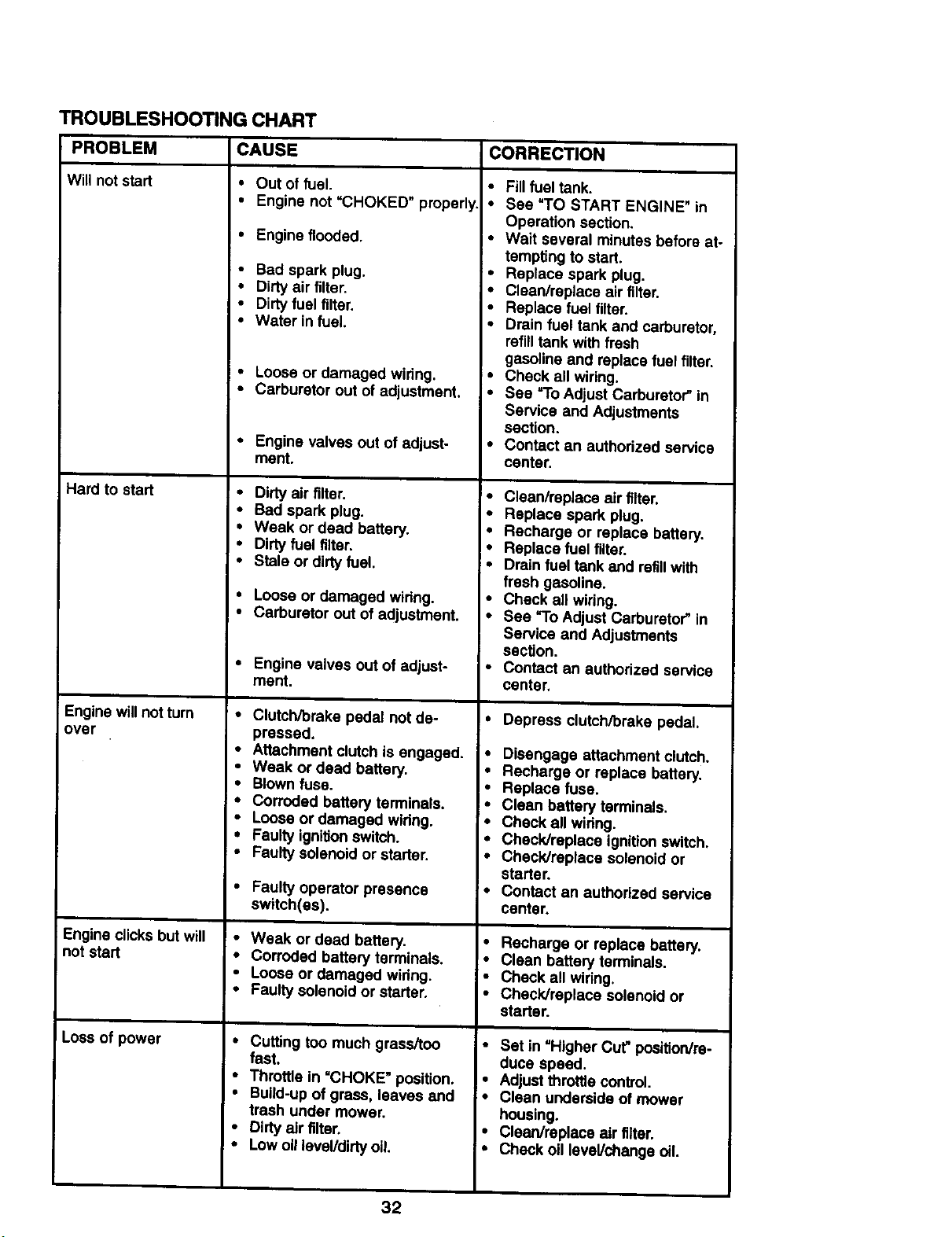
TROUBLESHOOTING CHART
PROBLEM CORRECTION
Will not start
Hard to start
Engine willnot turn
over
Engine clicks but will
not start
I Loss of power
CAUSE
• Out of fuel.
• Engine not "CHOKED" properly.
• Engine flooded.
• Bad spark plug.
• Dirty air filter.
• Dirty fuel filter.
• Water in fuel.
• Loose or damaged wiring.
• Carburetor out of adjustment.
• Engine valves out of adjust-
ment.
• Dirtyair filter.
• Bad spark plug.
• Weak or dead battery.
• Dirtyfuel filter.
• Stale or dirtyfuel.
• Louse or damaged wiring.
• Carburetor out of adjustment.
• Engine valves out of adjust-
ment.
• Clutch/brake pedal not de-
pressed.
• Attachment clutch is engaged.
• Weak or dead battery.
• Blown fuse.
• Corroded battery terminals.
• Loose or damaged wldng.
• Faulty ignitionswitch.
• Faulty solenoid or starter.
• Faulty operator presence
switch(as).
• Weak or dead battery.
• Corroded battery terminals.
• Loose or damaged widng.
• Faulty solenoid or starter.
• Cuffing too much grass/tou
fast.
• Throttle in "CHOKE" position.
• Build-up of grass, leaves and
trash under mower.
• Dirty air filter.
• Low oil level/dirty oil.
• Fill fuel tank.
• See "TO START ENGINE" in
Operation section.
• Wait several minutes before at-
tempting to start.
• Replace spark plug.
• Clean/replace air filter.
• Replace fuel filter.
• Drain fuel tank and carburetor,
refill tank with fresh
gasoline and replace fuel filter.
• Check all wiring.
• See "To Adjust Carburetor" in
Service and Adjustments
section.
• Contact an authodzed service
center.
• Clean/replace air filter.
• Replace spark plug.
• Recharge or replace battery.
• Replace fuel filter.
=• Drain fuel tank and refillwith
fresh gasoline.
• Check all wiring.
• See "To Adjust Carburetor" in
Service and Adjustments
section.
• Contact an authodzed service
center.
• Depress clutch/brake pedal.
• Disengage attachment clutch.
• Recharge or replace battery.
• Replace fuse.
• Clean battery terminals.
• Check all widng.
• Check/replace ignitionswitch.
• Check/replace solenoid or
starter.
• Contact an authorized service
center.
• Recharge or replace battery.
• Clean battery terminals.
• Check all wiring.
• Check/replace solenoid or
starter.
• Set in "Higher Cut" position/re-
l• duce speed.
Adjust throttle control.
;• Clean underside of mower
housing.
• Cleerdreptace air filter.
• Check oil level/change oil.
32
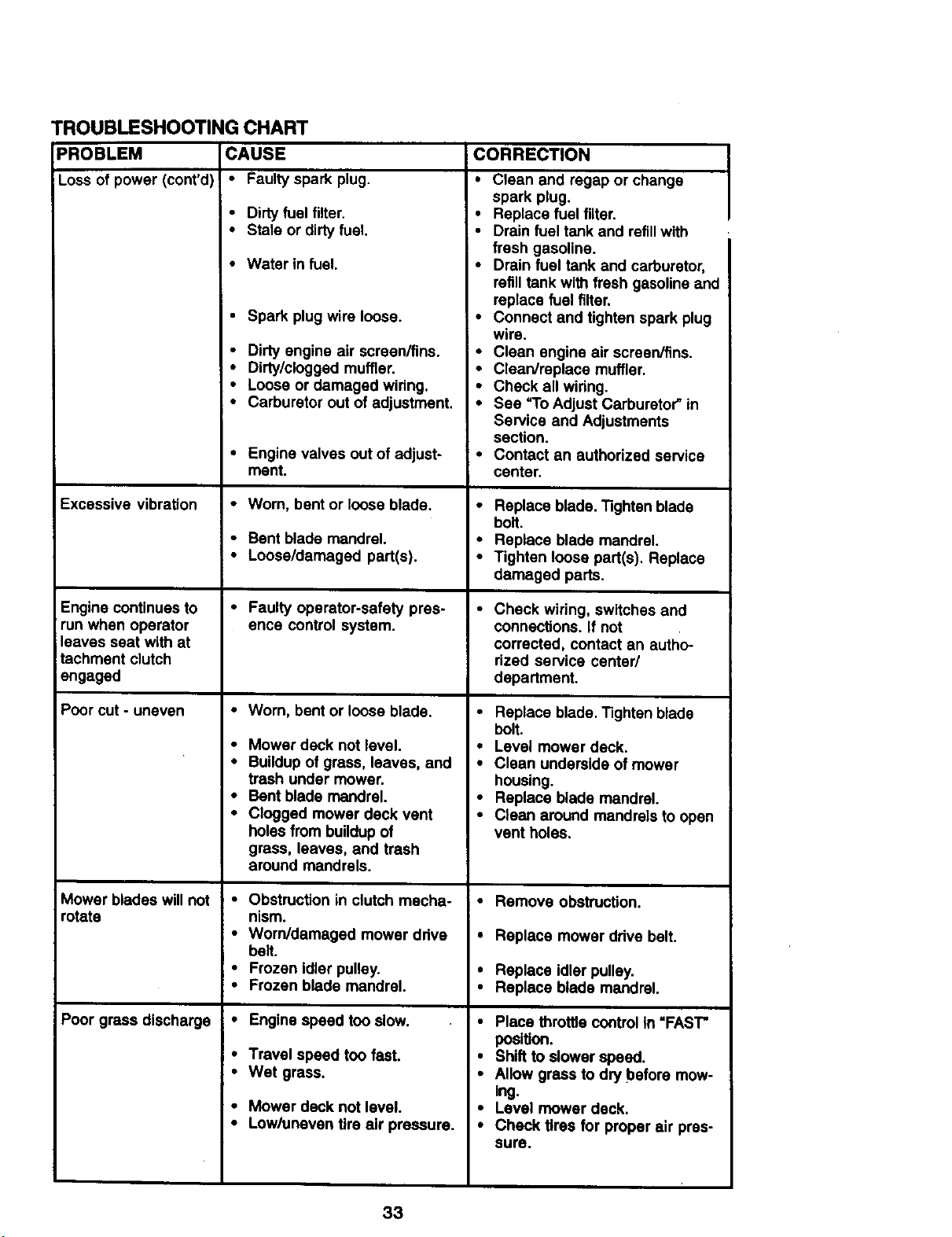
TROUBLESHOOTING CHART
PROBLEM CAUSE
Loss of power (cont'd) • Faulty spark plug.
Excessive vibration
Engine continues to
run when operator
leaves seat with at
tachment clutch
engaged
Poor cut - uneven
Mower blades will not
rotate
Poor grass discharge
• Dirty fuel filter.
• Stale or dirtyfuel.
• Water in fuel.
• Spark plug wire loose.
• Dirty engine air screen/fins.
• Dirty/clogged muffler.
• Loose or damaged wiring.
• Carburetor out of adjustment.
• Engine valves out of adjust-
ment.
• Worn, bent or loose blade.
• Bent blade mandrel.
• Loose/damaged part(s).
• Faulty operator-safety pres-
ence control system.
• Worn, bent or loose blade.
• Mower deck not level.
• Buildup of grass, leaves, and
trash under mower.
• Bent blade mandrel.
• Clogged mower deck vent
holes from buildupof
grass, leaves, and trash
around mandrels.
• Obstruction in clutch mecha-
nism.
• Worn/damaged mower ddve
belt.
• Frozen idler pulley.
• Frozen blade mandrel.
• Engine speed too slow.
• Travel speed too fast.
• Wet grass.
• Mower deck not level.
• Low/uneven tire air pressure.
i CORRECTION
• Clean and rogap or change
spark plug.
• Replace fuel filter.
• Drain fuel tank and refillwith
fresh gasoline.
• Drain fuel tank and carburetor,
refill tank with fresh gasoline and
replace fuel filter.
• Connect and tighten spark plug
wire.
• Clean engine air screen/fins.
• Clean/replace muffler.
• Check all widng.
• See "To Adjust Carburetor" in
Service and Adjustments
section.
• Contact an authorized service
center.
• Replace blade. Tighten blade
bolt.
• Replace blade mandrel.
• Tighten loose part(s), Replace
damaged parts.
• Check widng, switches and
connections. If not
corrected, contact an autho-
rized service center/
department.
• Replace blade. Tighten blade
bolt.
• Level mower deck.
• Clean underside of mower
housing.
• Replace blade mandrel.
• Clean around mandrels to open
vent holes.
Remove obstruction.
Replace mower drive belt.
Replace idler pulley.
Replace blade mandrel.
Place throffie controlin "FAST"
position.
Shift to slower speed.
Allow grass to dry before mow-
Ing.
Level mower deck.
Check tires for proper air pres-
sure.
33
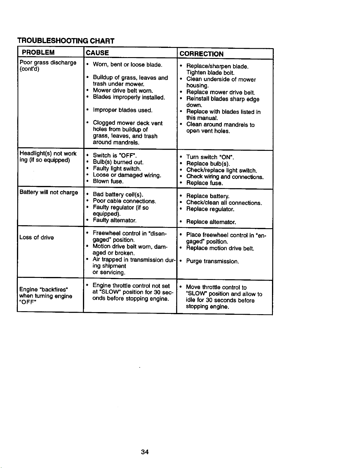
TROUBLESHOOTINGCHART
PROBLEM
Poor grass discharge
(cont'd)
Headlight(s) not work
ing (if so equipped)
Battery will not charge
Loss of drive
Engine "backfires"
when turning engine
"OFF"
CAUSE
• Worn, bent or loose blade.
• Buildup of grass, leaves and
trash under mower.
• Mower drive belt worn.
• Blades improperly installed.
• Improper blades used.
• Clogged mower deck vent
holes from buildup of
grass, leaves, and trash
around mandrels.
• Switch is "OFF'.
• Bulb(s) bumed out.
• Faulty light switch.
• Loose or damaged wiring.
• Blown fuse.
• Bad battery cell(s).
• Poor cable connections.
• Faulty regulator (if so
equipped).
• Faulty alternator.
• Freewheel control in "disen-
gaged" position.
• Motion drive belt wom, dam-
aged or broken.
• Air trapped in transmission dur-
ing shipment
or servicing.
• Engine throttle controlnot set
at "SLOW" position for 30 sec-
onds before stopping engine.
CORRECTION
• Replace/sharpen blade.
Tighten blade bolt.
• Clean underside of mower
housing.
• Replace mower drive belt.
• Reinstall blades sharp edge
down.
• Replace with blades listed in
this manual.
• Clean around mandrels to
open vent holes.
• Turn switch =ON'.
• Replace bulb(s).
• Check/replace light switch.
• Check wiringand connections.
• Replace fuse.
• Replace battery.
• Check/clean all connections.
• Replace regulator.
• Replace alternator.
• Place freewheel controlin "en-
gaged" position.
• Replace motion drive belt.
I" Purge transmission.
• Move throttle control to
"SLOW_ position and allow to
idle for 30 seconds before
stopping engine.
34
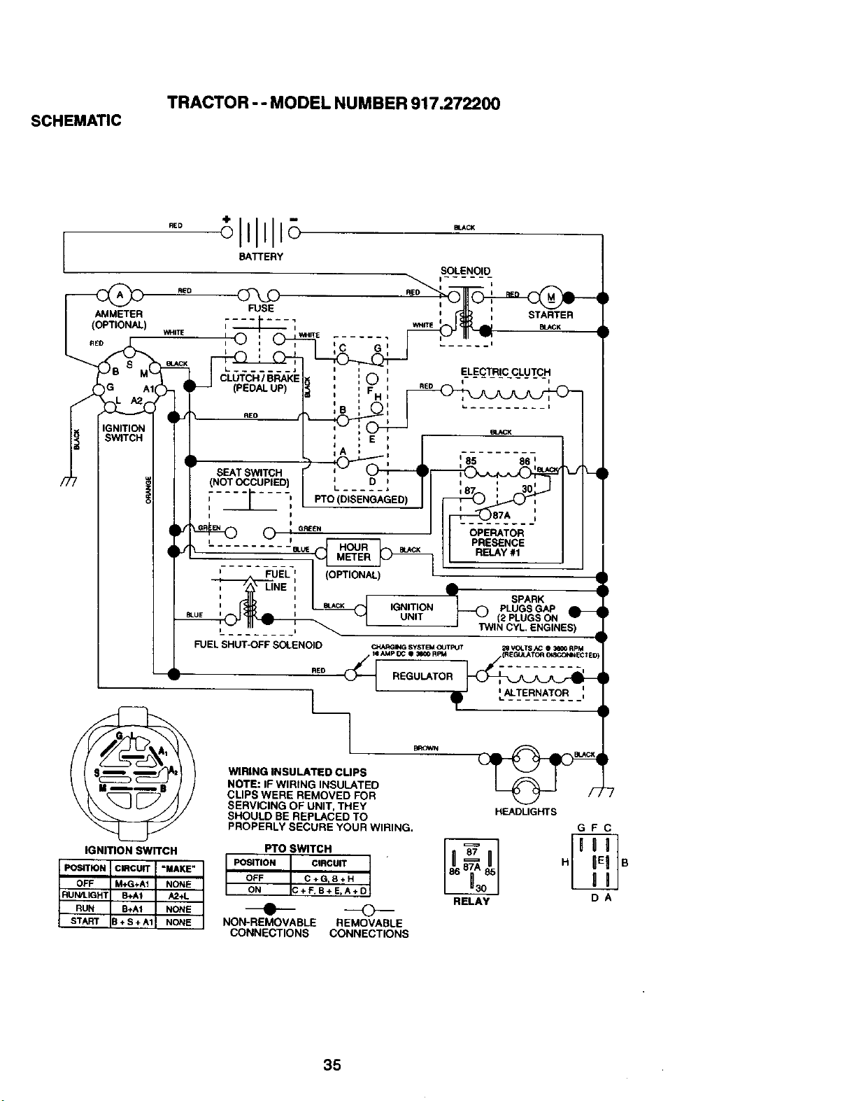
TRACTOR -- MODEL NUMBER 917.272200
SCHEMATIC
/7
RED
RE0
AMMETER
) WHITE
ED
OPERATOR
PRESENCE
RELAY#1
FUEL (OPTIONAL)
L
FUEL SHUT-OFF SOLENOID
REO
l_
_) SPARK •
IGNITION PLUGS GAP
UNIT (2 PLUGS ON
J TWIN CYL ENGINES)
IGNITION SWITCH
POSITION CIRCUIT =MAKE"
OFF M+G+AI NONE
START B+S+A1 NONE
RUN/LIGHT B+AI A2+L
RUN B+AI NONE
WIRING INSULATED CUPS
NOTE: IF WIRING INSULATED
CLIPS WERE REMOVED FOR
SERVICING OF UNIT. THEY
SHOULD BE REPLACED TO
PROPERLY SECURE YOUR WIRING.
Fro SWITCH
POSITION CIRCUIT
OFF C+G, 8+H
ON C+F,B+ E,A+D
NON-REMOVABLE REMOVABLE
CONNECTIONS CONNECTIONS
HEADLIGHTS
GFC
BELAY D A
35
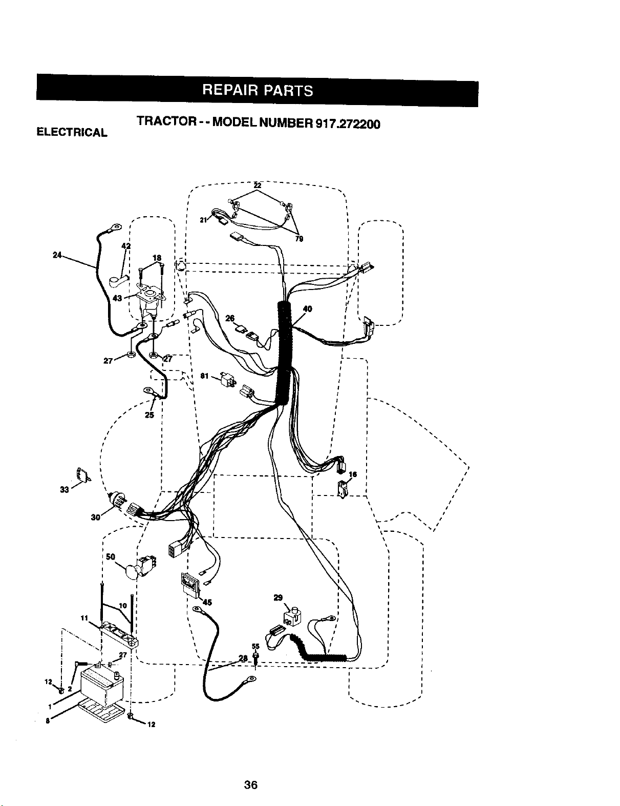
ELECTRICAL
TRACTOR - - MODEL NUMBER 917.272200
2714
I
I
I
I
I
I
I
I
i I ,
i I
i I
/
I
I
I
/
/
/
36
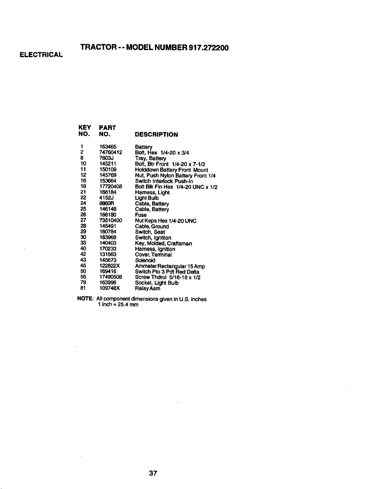
TRACTOR -- MODEL NUMBER 917.272200
ELECTRICAL
KEY PART
NO. NO. DESCRIPTION
1 163465 Battery
2 74760412 Bolt, Hex 1/4-20 x 3/4
8 7603J Tray, Battery
10 145211 Bolt, Btr Front 1/4-20 x 7-1/2
11 150109 HolddownBattery Front Mount
12 145769 Nut, Push Nylon Battery Front 1/4
16 153664 Switch Interlock Push-In
18 17720408 Bolt BIk Fin Hex 1/4-20 UNC x 1/2
21 166184 Hamess, Light
22 4152J LightBulb
24 8860R Cable, Battery
25 146148 Cable, Battery
26 166180 FUSS
27 73510400 Nut Keps Hax 1/4-20 UNC
28 145491 Cabio,Ground
29 160784 Switch, Seat
30 163968 Switch, Ignition
33 140403 Key, Molded, Craftsman
40 170233 Harness, Ignition
42 131563 Cover,Terminal
43 145673 Solenoid
45 122822X AmmeterRectangular 15Amp
50 169416 Switch Pro3 Pdt Red Delta
55 17490508 Screw Thdrol 5/16-18 x 1/2
79 163996 Socket, Light Bulb
81 109748X RelayAsm
NOTE: Allcomponent dimensionsgiven in U.S. inches
1inch = 25.4 mm
37
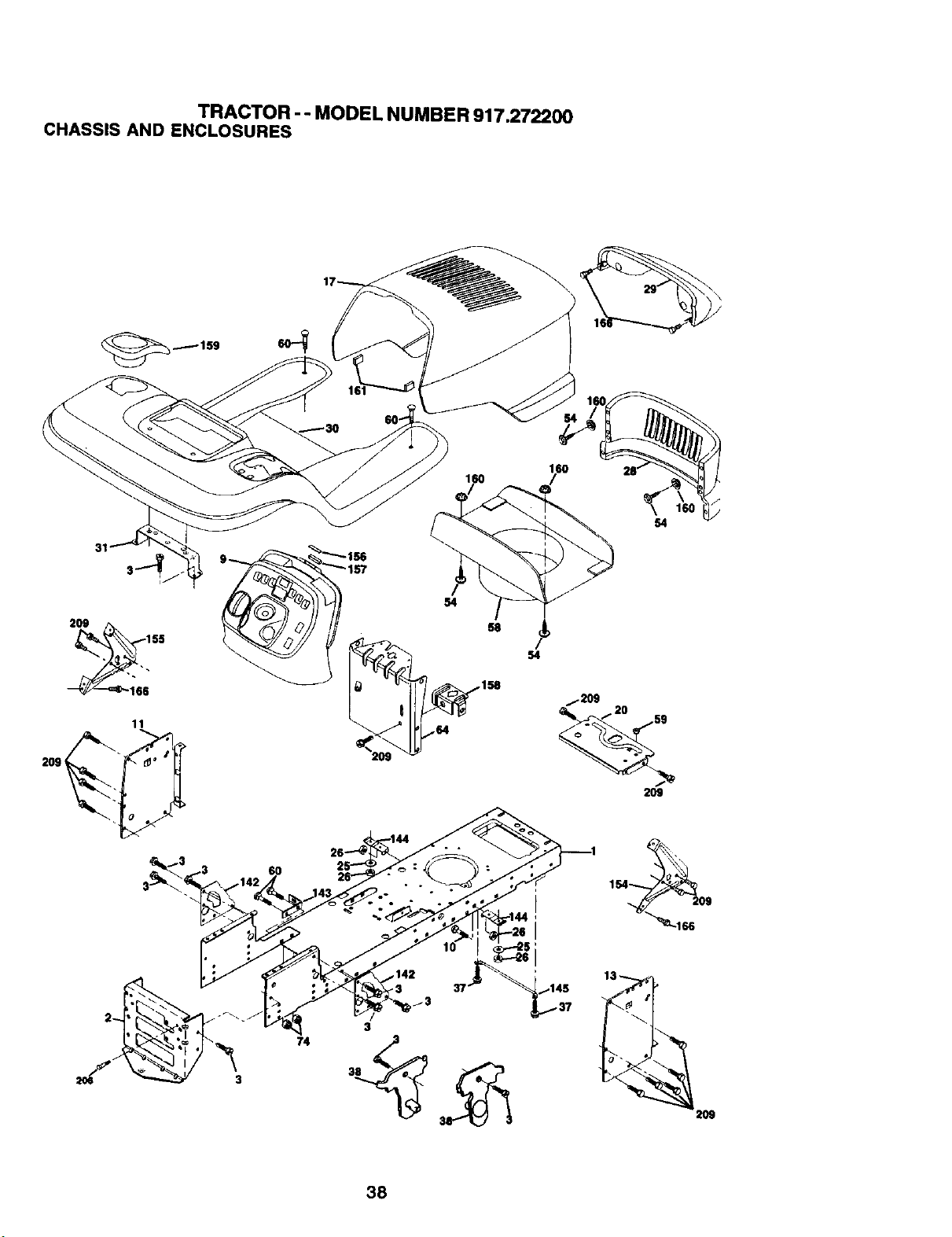
TRACTOR -- MODEL NUMBER917.272200
CHASSISAND ENCLOSURES
160
31
60
54
2O9
38
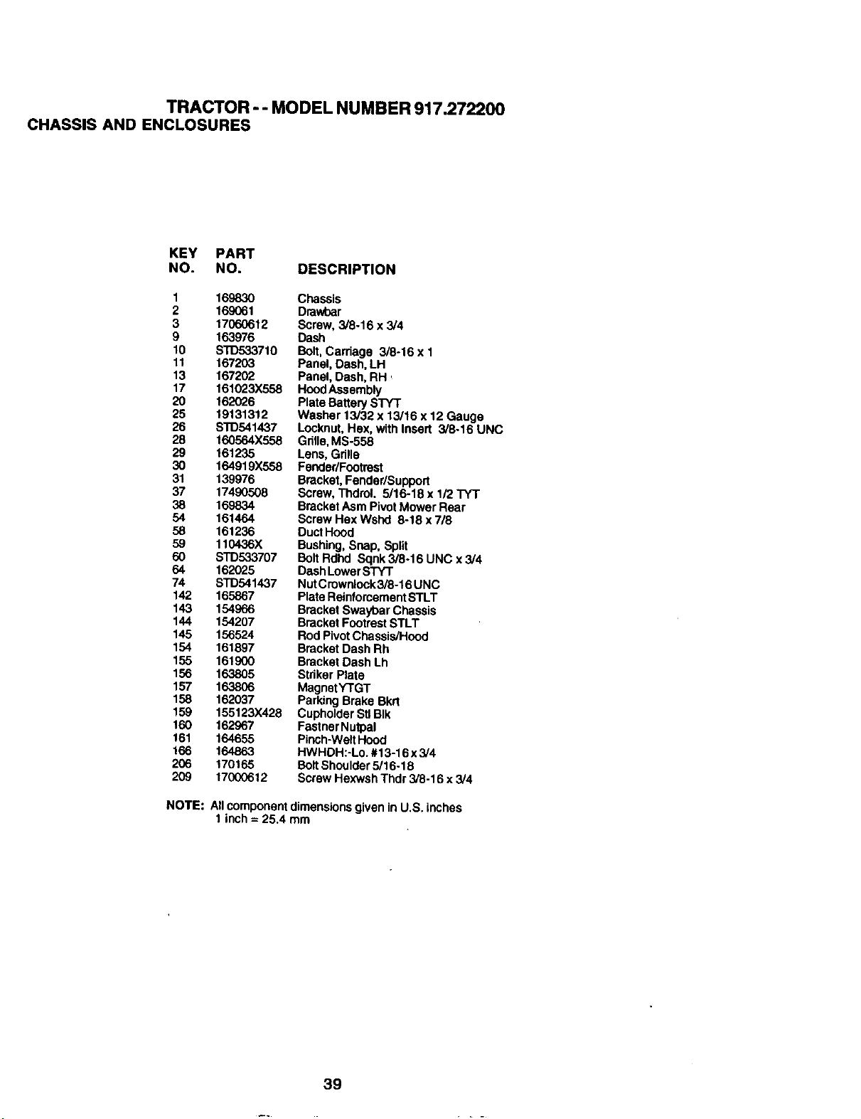
TRACTOR -- MODEL NUMBER 917.272200
CHASSIS AND ENCLOSURES
KEY PART
NO. NO. DESCRIPTION
1 169830 Chassis
2 169061 Dmwbar
3 17060612 Screw, 3/6-16 x 3/4
9 163976 Dash
10 STD533710 Bolt,Carriage 3/8-16 x 1
11 167203 Panel, Dash, LH
13 167202 Panel, Dash, RH
17 161023X558 HoodAssembly
20 162026 Plate Battery STYT
25 19131312 Washer 13/32 x 13/16 x 12 Gauge
26 STD541437 Locknut, Hex, with Insert 3/8-16 UNC
28 160564X558 Gdlle,MS-558
29 161235 Lens, Grille
30 164919X558 Fender/Footrest
31 139976 Bracket, Fender/Support
37 17490508 Screw, Thdrol. 5/16-18 x 1/2 TYT
38 169834 Bracket Asm PivotMower Rear
54 161464 Screw Hax Wshd 8-18 x 718
58 161236 DuctHood
59 110436X Bushing, Snap, Split
60 STD533707 Bolt Rdhd Sqnk3/8-16 UNC x 3/4
64 162025 Dash LowerSTY'r
74 STD541437 NutCrowniock3/8-16 UNC
142 165867 Plata ReinforcementSTLT
143 154966 Bracket Sway'oarChassis
144 154207 Bracket FootrestSTLT
145 156524 Rod PivotChassis/Hood
154 161897 Bracket Dash Rh
155 161900 Bracket Dash Lh
156 163805 Striker Plate
157 163806 MagnetY'rGT
158 162037 Parking Brake Bkrt
159 155123X428 CupholderSUBIk
160 162967 FastnerNutpal
161 164655 Pinch-WeltHood
166 164863 HWHDH:-Lo. #13-16 x 3/4
206 170165 BOltShoulder5/16-18
209 17000612 Screw Hexwsh Thdr 3/6-16 x 3/4
NOTE:
All component dimensionsgiven in U.S. inches
1 inch = 25.4 mm
39
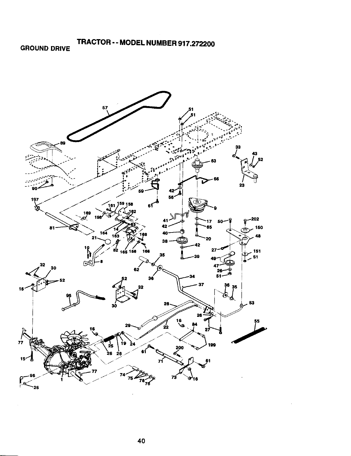
TRACTOR -- MODEL NUMBER 917.272200
GROUND DRIVE
32
p 52
_3 36
2
30
43
77
16
16
55
40
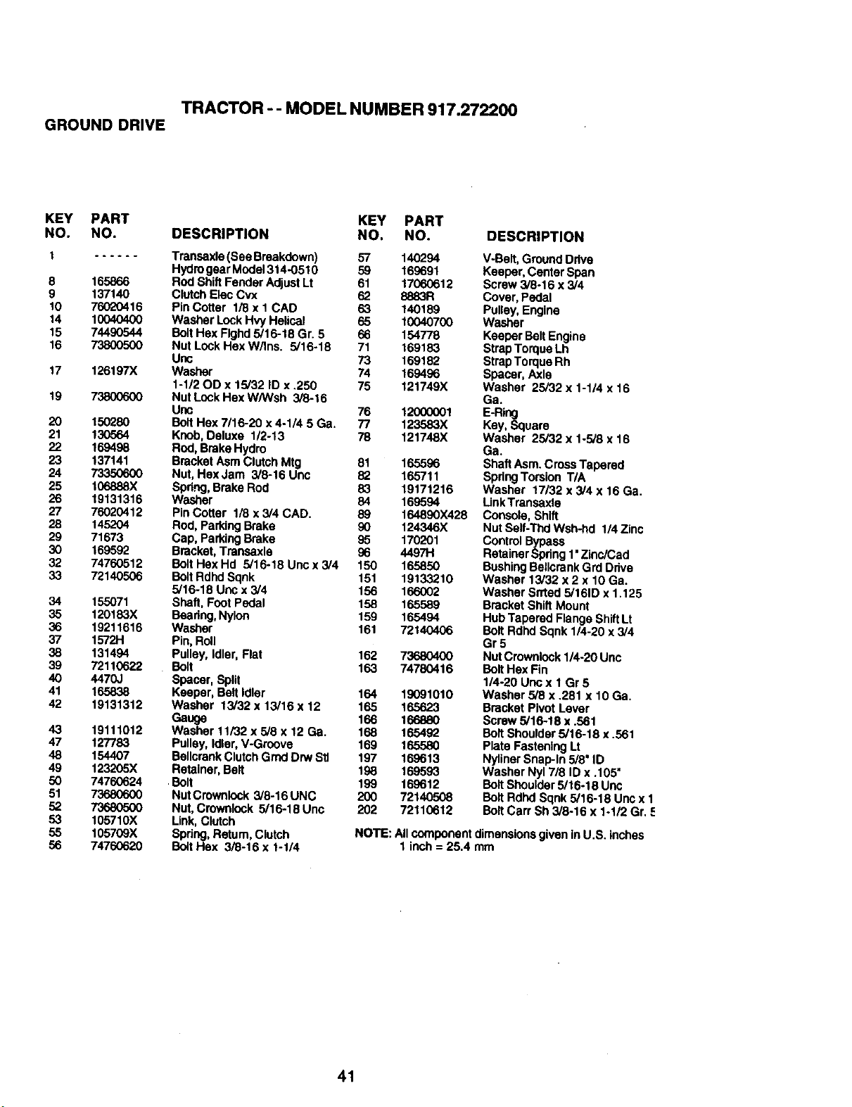
TRACTOR - - MODEL NUMBER 917.272200
GROUND DRIVE
KEY PART KEY PART
NO. NO. DESCRIPTION NO. NO. DESCRIPTION
1 ...... Transaxle(See Breakdown) 57 140294 V-Belt, Ground Drive
Hydrogear Model314-0510 59 169691 Keeper, Center Spen
8 165866 Rod Shift Fender AdjustLt 61 17060612 Screw 3/8-16 x 3/4
9 137140 Clutch E!ec Cvx 62 8883R Cover, Pedal
10 76020416 PinCotter 1/8 x 1 CAD 63 140189 Pulley,Engine
14 10040400 Washer LockHvy Helical 65 10040700 Washer
15 74490544 BoltHex Flghd5/16-18 Gr. 5 66 154778 Keeper Belt Engine
16 73800500 Nut Look Hex W,'tns. 5/16-18 71 169183 StrapTorque Lh
Unc 73 169182 Strap Torque Rh
17 126197X Washer 74 169496 Spacer, Axle
1-112OD x 15/32 ID x .250 76 121749X Washer 25/32 x 1-1/4 x 16
19 73800600 Nut Lock Hex W/Wsh 3/8-16 Ga.
Unc 76 1200(3001 E-Ring
20 150280 Bolt Hex 7/16-20 x 4-1/4 5 Ga. 77 123583X Key, Square
21 130564 Knob, Deluxe 1/2-13 78 121748X Washer 25/32 x 1-5/8 x 16
22 169498 Rod, Brake Hydro Ga.
23 137141 Bracket Asm Clutch Mtg 81 165596 Sh,ldtAsm. CrossTapered
24 73350600 Nut, HexJam 3/8-16 Unc 82 165711 SpdngTorsion T/A
25 106888X Spdng,Brake Rod 83 19171216 Washer 17132x 3/4 x 16 Ga.
26 19131316 Washer 84 169594 Link Transaxle
27 76020412 PinCotter 1/8 x 3/4 CAD. 89 164890X428 Console, Shift
28 145204 Rod, ParkingBrake 90 124346X Nut Selt-Thd Wsh-hd 1/4 Zinc
29 71673 Cap, Parking Brake 95 170201 Control Bypass
30 169592 Bracket, Transaxle 96 4497H Retainer Spdng 1"Zinc/Cad
32 74760512 Bolt Hex Hd 5/16-18 Unc x 3/4 150 165850 BushingBellcrankGrd Drive
33 72140506 BoltRdhd Sopk 151 19133210 Washer 13/32 x 2 x 10 Gs.
5/16-18 Uric x 3/4 156 166002 Washer Srrted 5/161Dx 1.125
34 155071 Shaft, Foot Pedal 158 165589 Bracket Shift Mount
35 120183X Beadng, Nylon 159 165494 Hub Tapered Flange ShiftLt
36 19211616 Washer 161 72140406 Bolt Rdhd Sqnk 1/4-20 x3/4
37 1572H Pin,Roll Gr 5
38 131494 Pulley, Idler, Flat 162 73680400 Nut Crownlock114-20Uric
39 72110622 Bolt 163 74780416 Bolt Hex Fin
40 4470J Spacer, Split 1/4-20 Unc x 1 Gr 5
41 165838 Keeper, Belt |_er 164 19091010 Washer 5/8 x .281 x 10 Gs.
42 19131312 Washer 13/32 x 13/16 x 12 165 16.5623 Bracket Pivot Lever
Gauge 166 166880 Screw 5/16-18 x .561
43 19111012 Washer 11/32 x 5/8 x 12 Ga. 168 165492 Bolt Shoulder5/16-18 x .561
47 127783 Pulley, Idler, V-Groove 169 165580 Plate Fastening Lt
48 154407 BellcrankClutch Grnd Drw Sit 197 169613 Nyliner Snap-In 5/8' ID
49 123205X Retainer, Belt 198 169593 Washer Nyl 7/8 ID x .105=
50 74760624 Bolt 199 169612 Bolt Shoulder5/16-18 Unc
51 73680600 NutCrownlock 3/8-16 UNC 200 72140508 BoltRdhd Sqnk 5/16-18 Unc x 1
52 73680500 Nut, Crownk_ck5/16-18 Unc 202 72110612 BoltCart Sh 3/8-16 x 1-1/2 Gr. =_
53 105710X Link,Clutch
55 105709X Spring,Return, Clutch NOTE: All component dimensionsgiven in U.S. inches
56 74760620 BoltHex 3/8-16 x 1-1/4 1 inch = 25.4 mm
41
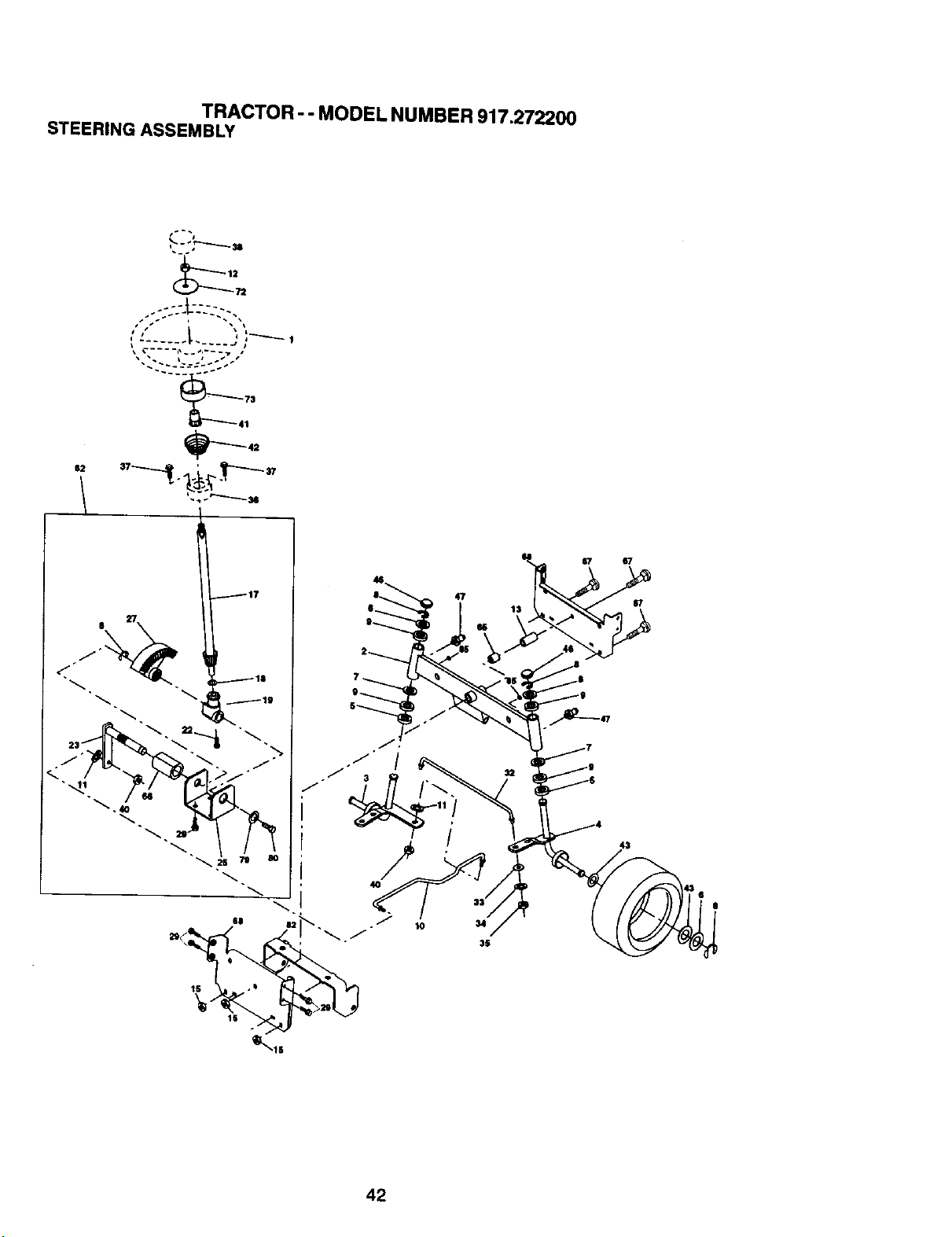
TRACTOR - - MODEL NUMBER 917.272200
STEERING ASSEMBLY
71
..:::.L-:--_-::.,
41
1S
lS
42
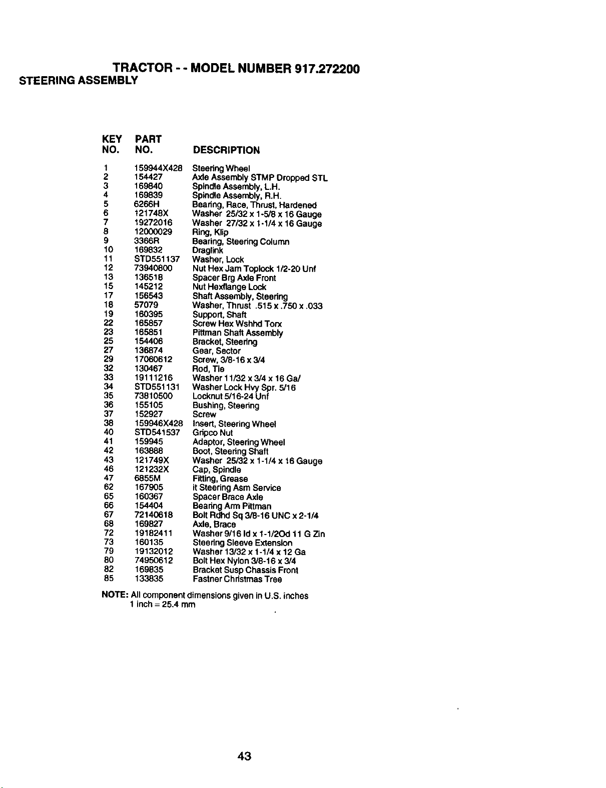
TRACTOR - - MODEL NUMBER 917.272200
STEERING ASSEMBLY
KEY PART
NO. NO. DESCRIPTION
1 159944X428
2 154427
3 169840
4 169839
5 6266H
6 121748X
7 19272016
8 12000029
9 3366R
10 169832
11 STD551137
12 73940800
13 136518
15 145212
17 156543
18 57079
19 160395
22 165857
23 165851
25 154406
27 136874
29 17060612
32 130467
33 19111216
34 STD551131
35 73810500
36 155105
37 152927
38 159946X428
40 STD541537
41 159945
42 163888
43 121749X
46 121232X
47 6855M
62 167905
65 160367
66 154404
67 72140618
68 169827
72 19182411
73 160135
79 19132012
80 74950612
82 169835
85 133835
SteeringWheel
Axle Assembly STMP Dropped STL
SpindleAssembly, LH.
SpindleAssembly, R.H.
Bearing, Race,Thrust, Hardened
Washer 25/32 x 1-5/8 x 16 Gauge
Washer 27/32 x I-1/4 x 16 Gauge
Ring, Klip
Bearing, SteeringColumn
Draglink
Washer, Lock
Nut Hex Jam Toplcck 1/2-20 Unf
Spacer BrgAxle Front
Nut Hexflange Lock
Shaft Assembly,Steering
Washer, Thrust .515 x .750 x .033
Support, Shaft
Screw Hex Wshhd Torx
Pittman Shaft Assembly
Bracket, Steering
Gear, Sector
Screw, 3/8-16 x 3/4
Rod, Tie
Washer 11..'32x 3/4 x 16 Ga/
Washer Lock Hvy Spr.5/16
Locknut 5/16.24 Unf
Bushing, Steering
Screw
Insert, SteeringWheel
GripcoNut
Adaptor,Steering Wheel
Boot,Steering Shaft
Washer 25/32 x 1-1/4 x 16Gauge
Cap, Spindle
Fitting,Grease
it SteeringAsm Service
Spacer Brace Axle
BearingArm Pittman
BoltRdhd Sq 3/8-16 UNC x 2-1/4
Axle, Brace
Washer 9/16 Id x 1-1/2Od 11 G Zin
Steering Sleeve Extension
Washer 13/32 x 1-1/4 x 12 Ga
BoltHex Nylon3/8-16 x 3/4
Bracket Susp ChassisFront
Fastner ChristmasTree
NOTE: All componentdimensions given in U.S. inches
1 inch = 25.4 mm
43
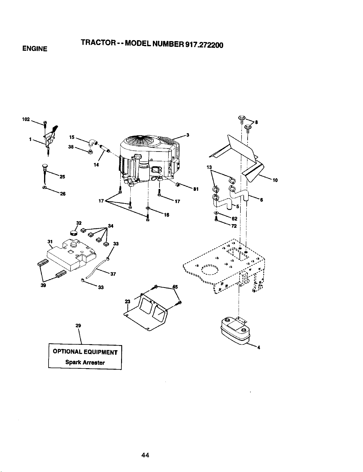
TRACTOR -- MODEL NUMBER 917.272200
ENGINE
31
14
32
33
23
13
"81
29
OPTIONAL EQUIPMENT 1Spark Arrester
44
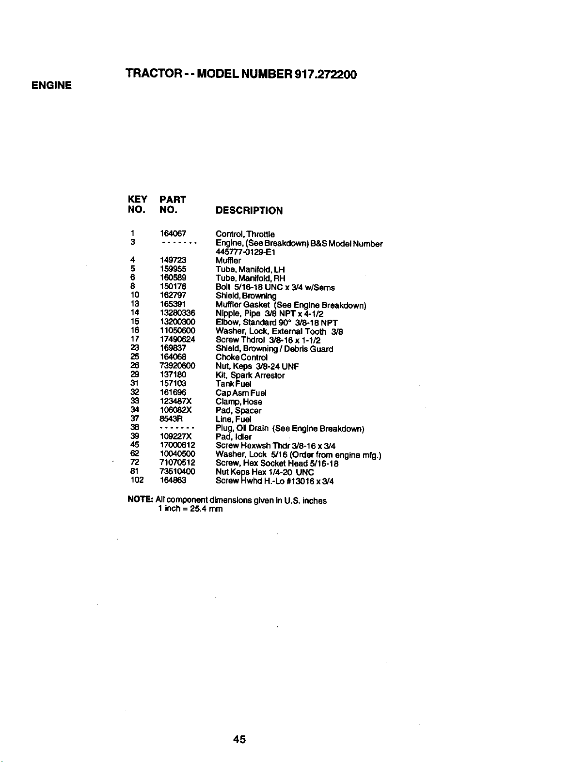
TRACTOR -- MODEL NUMBER 917.272200
ENGINE
KEY PART
NO. NO. DESCRIPTION
1
3
164O67
4 149723
5 159955
6 160589
8 150176
10 162797
13 16.5391
14 13280336
15 13200300
16 11050600
17 17490624
23 169837
25 164068
26 73920600
29 137180
31 157103
32 161696
33 123487X
34 106082X
37 8543R
38 .......
39 109227X
45 17000612
62 10040500
72 71070512
81 73510400
102 164863
Control, Thmtlla
Engine, (See Breakdown) B&S ModelNumber
445777-0129-E1
Muffler
Tube, Manifold,LH
Tube, Manifold,RH
Bolt 5/16-18 UNC x 3/4 w/Sems
Shield,Browning
MufflerGasket (See EngineBreakdown)
Nipple, Pipe 3/8 NPTx4-1/2
Elbow, Standard 90° 3/8-18 NPT
Washer, Look, External Tooth 3/8
Screw Thdrol 3/8-16 x 1-1/2
Shield, Browning/ Debds Guard
ChokeControl
Nut, Keps 3/8-24 UNF
Kit, Spark Arrestor
Tank Fuel
CapAsm Fuel
Clamp,Hose
Pad, Spacer
Line,Fuel
Plug,Oil Drain (See EngineBreakdown)
Pad, Idler
Screw Hexwsh Thdr 3/8-16 x 3/4
Washer, Lock 5/16 (Order from engine mfg.)
Screw, Hex Socket Head 5/16-18
Nut Kaps Hex 1/4-20 UNC
Screw Hwhd H.-Lo #13016 x 3/4
NOTE: Allcomponent dimensionsgiven In U.S. inches
1 inch = 25.4 mm
45
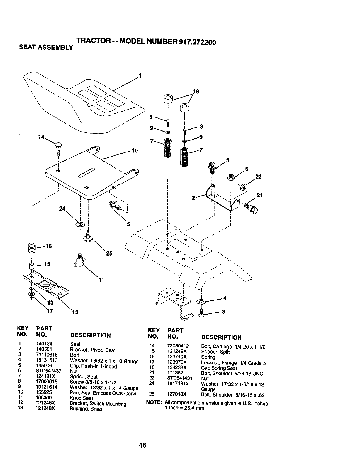
TRACTOR -- MODEL NUMBER 917.272200
SEAT ASSEMBLY
11
12
KEY
NO.
1
2
3
4
5
6
7
8
9
10
11
12
13
,18
PART KEY PART
NO. DESCRIPTION NO. NO. DESCRIPTION
21
140124 Seat 14 72050412 Bolt,Carriage 1/4-20 x 1-1/2
140551 Bracket, Pivot, Seat 15 121249X Spacer, Split
71110616 Bolt 16 123740X Spring
19131610 Washer 13/32 x 1 x 10 Gauge 17 123976X Locknut, Flange 1/4 Grade 5
145006 Clip, Push-In Hinged 18 124238X Cap SpringSeat
STD541437 Nut 21 171852 Bolt, Shoulder 5/16-18 UNC
124181X Spring,Seat 22 S'TD541431 Nut
17000616 Screw 3/8-16 x 1-1/2 24 19171912 Washer 17132 x 1-3/16 x 12
19131614 Washer 13/32 x 1 x 14 Gauge Gauge
155925 Pan, Seat EmbossQCK Conn. 25 127018X Bolt, Shoulder 5/16-18 x .62
166369 Knob Seat
121246X Bracket, SwitchMounting NOTE: Allcomponent dimensionsgiven in U.S. inches
121248X Bushing, Snap 1 inch = 25.4 mm
46
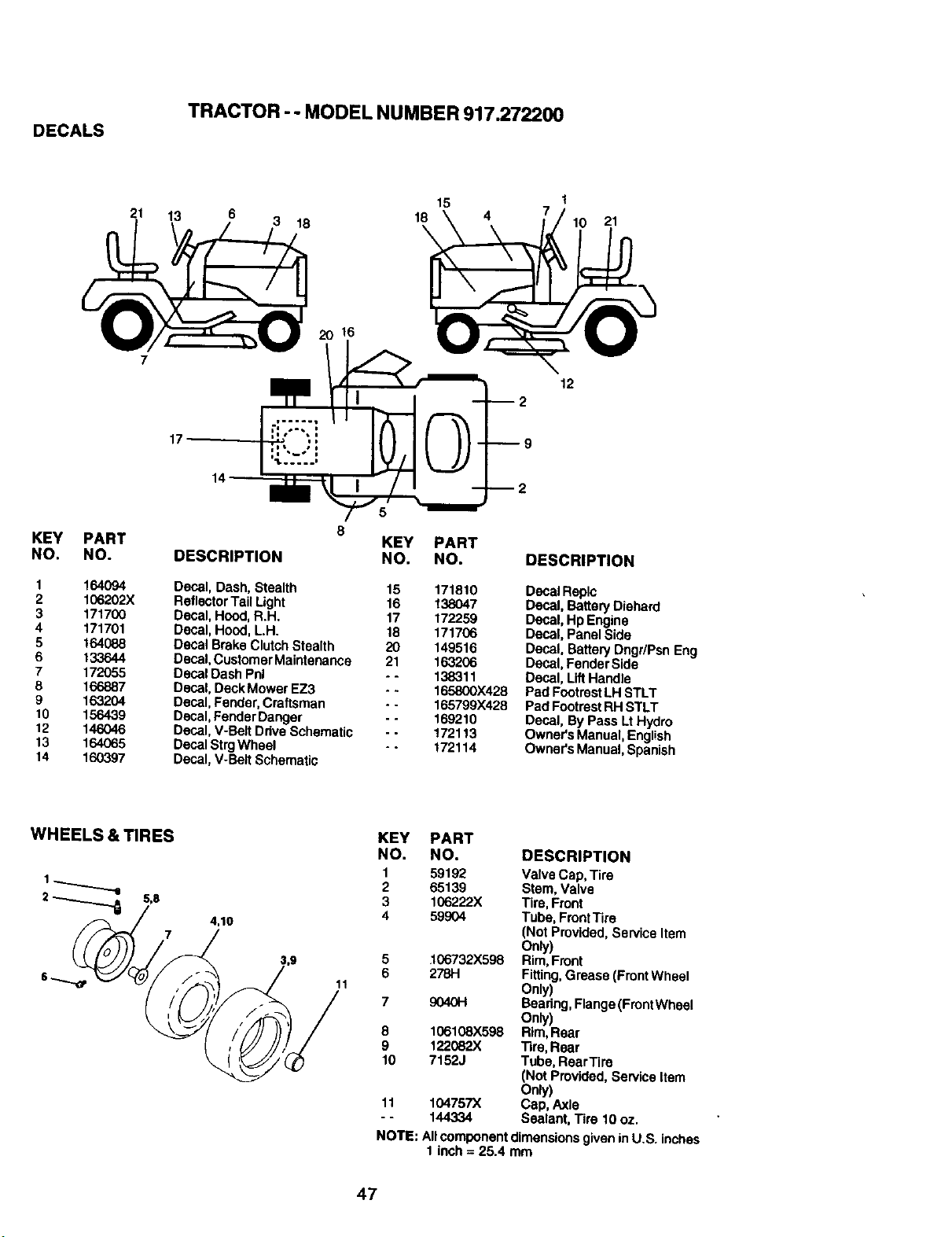
TRACTOR -- MODEL NUMBER 917.272200
DECALS
21 13 6 3 18
15 !
18 4 7
21
7
17
16
12
KEY PART
NO. NO.
1 164094
2 106202X
3 171700
4 171701
5 164088
6 133644
7 172055
8 166887
9 163204
10 156439
12 146046
13 164065
14 160397
8
KEY PART
DESCRIPTION NO. NO.
Decal, Dash, Stealth 15 171810
ReflectorTail Light 16 138047
Decal, Hood, R.H. 17 172259
Decal, Hood, L.H. 18 171706
Decal Brake Clutch Stealth 20 149516
Decal, Customer Maintenance 21 163206
Decal Dash Pnl - - 138311
Decal, Deck MowerEZ3 - - 165800X428
Decal,Fender, Craftsman - - 165799X428
Decal,FenderDanger - - 169210
Decal, V-Belt Drive Schematic -. 172113
Decal StrgWheel - - 172114
Decal, V-Bait Schemaf_c
DESCRIPTION
Decal Replc
Decal, Battery Diehard
Decal, Hp Engine
Decal, Panel Side
Decal, Battery Dngr/Psn Eng
Decal, Fender Side
Decal, LiftHandle
Pad FootrestLH STLT
Pad FootrestRH STLT
Decal, By Pass LtHydro
Owner's Manual, English
Owner's Manual, Spanish
WHEELS & TIRES
2 _ 5,S
7
4,10
11
KEY PART
NO. NO. DESCRIPTION
1 59192 Valve Cap, Tire
2 65139 Stem, Valve
3 106222X Tire, Front
4 59904 Tube, FrontTire
(Not Provided,Service Item
Only)
5 106732X598 Rim,Front
6 278H Fitting,Grease (FrontWheel
Only)
7 9040H Bearing, Flange (FrontWheal
Only)
8 106108X598 Rim,Rear
9 122082X Tire, Rear
10 7152J Tube, RearTire
(Not Provided, Barv_eaItem
Only)
11 104757X Cap, Axle
- - 144334 Sealant. Tire 10 oz.
NOTE: All component dimensionsgiven in U.S. inches
1 inch = 25.4 mm
47
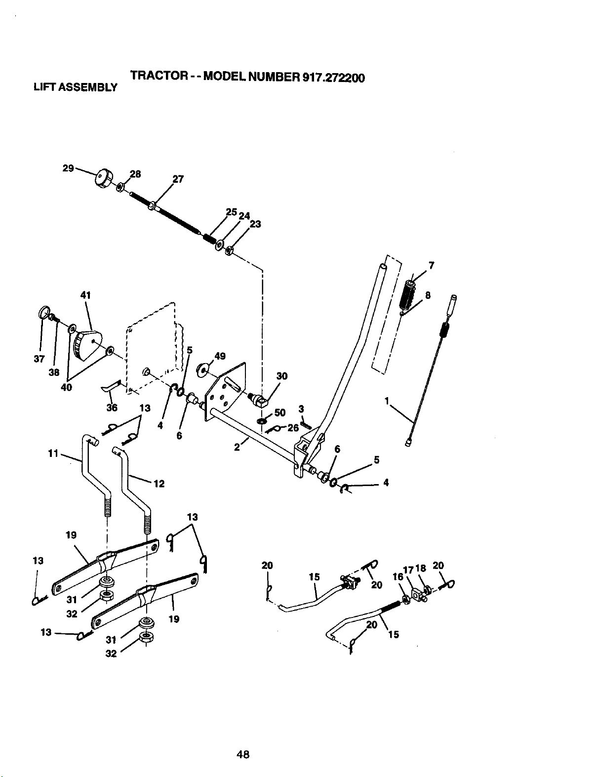
TRACTOR - - MODEL NUMBER 917.272200
LIFT ASSEMBLY
29_
28
27
23
7
41
40
3O
3
6
5
4
13
13
19
32
32
13
19
2O
15
15
20
48
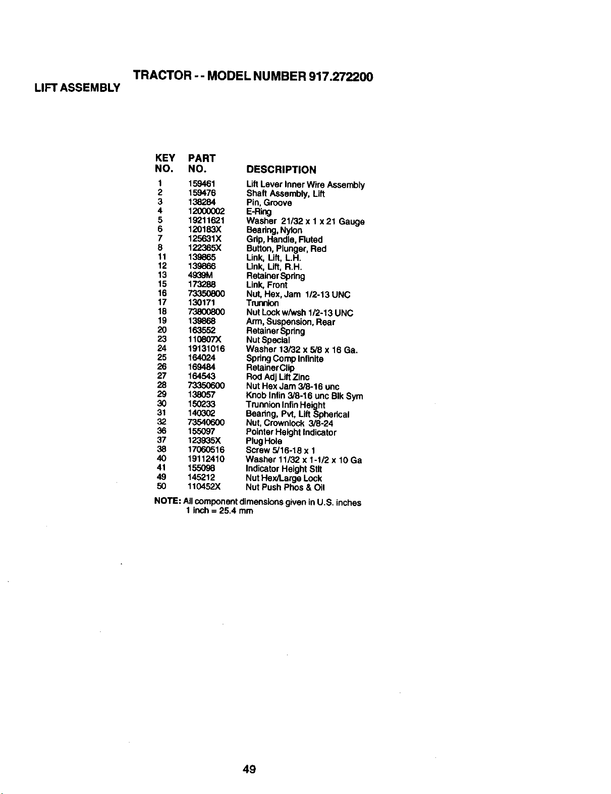
TRACTOR -- MODEL NUMBER 917.272200
LIFTASSEMBLY
KEY PART
NO. NO. DESCRIPTION
1 159461 LiftLever Inner Wire Assembly
2 159476 Shaft Assembly, Lift
3 138284 Pin. Groove
4 12000002 E-Ring
5 19211621 Washer 21/32 x 1 x 21 Gauge
6 120183X Bearing,Nylon
7 125631X Grip, HaP,dis, Fluted
8 122365X Button,Plunger, Red
11 139865 Link, Lift, L.H.
12 139866 Link, Lift, R.H.
13 4939M RetainerSpring
15 173288 Link,Front
16 _ Nut, Hex, Jam 1/2-13 UNC
17 130171 Trunnion
18 73800800 Nut Locl(wiwsh 1/2-13 UNC
19 139868 Arm, Suspension,Rear
20 163552 Retainer Spring
23 110607X Nut Special
24 19131016 Washer 13/32 x 5/8 x 16 Ga.
25 164024 SpringComp Infinite
26 169484 RetainerClip
27 164543 Rod AdjLilt Zinc
28 73350600 Nut Hex Jam 3/8-16 unc
29 138057 Knob Infin 3/8-16 unc BIk Sym
30 150233 TrunnionInfinHeight
31 140302 Beadng, Pvt, Lift Spherical
32 73540600 Nut, Cmwnlock 3/8-24
36 155097 PointerHeight Indicator
37 123935X PlugHole
38 17060516 Screw 5/16-18 x 1
40 19112410 Washer 11/32 x 1-1/2 x 10 Ga
41 155098 Indicator Height Stlt
49 145212 NutHex/Large Lock
50 110452X Nut Push Phos & Oil
NOTE: All componentdimensions given inU.S. inches
1inch = 25.4 mm
49
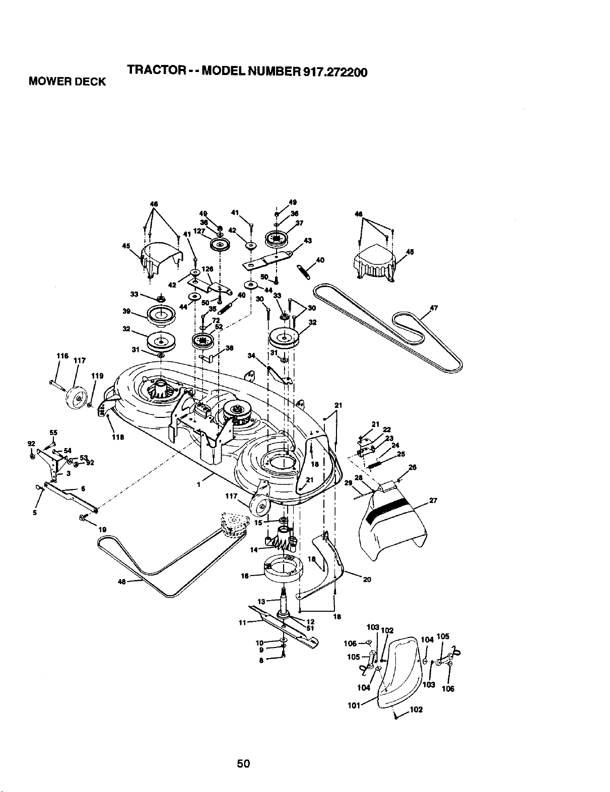
TRACTOR -- MODEL NUMBER917.272200
MOWERDECK
46
116
117
119
SS
19
117
21
21
22
26
5O
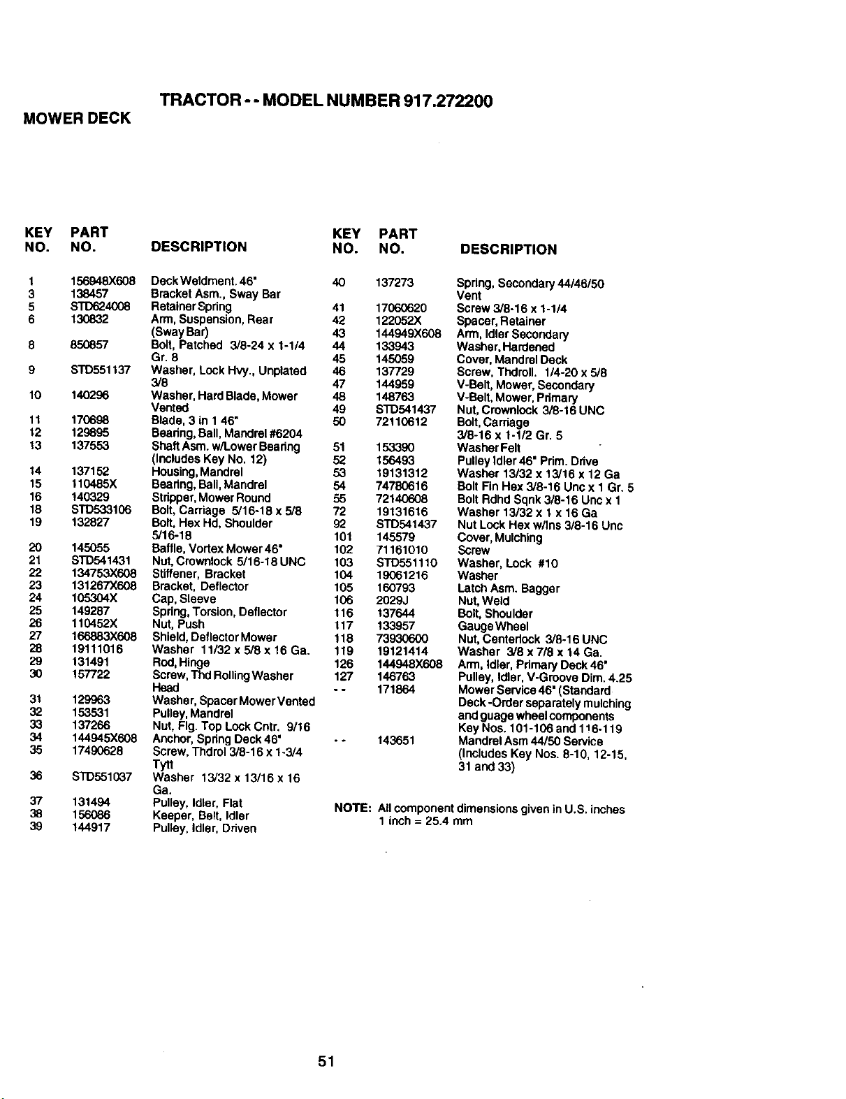
MOWER DECK
TRACTOR - - MODEL NUMBER 917.272200
KEY PART
NO. NO.
1
3
5
6
8
9
10
11
12
13
14
15
16
18
19
2O
21
22
23
24
25
26
27
28
29
3o
31
32
33
34
35
36
37
38
39
156948X608
138457
STD624008
130832
85O857
STD551137
140296
170698
129895
137553
137152
110485X
140329
STD533106
132827
145055
STD541431
134753X608
131267X608
105304X
149287
110452X
166883X608
19111018
131491
157722
129963
153531
137266
144945X608
17490628
STD551037
131494
156086
144917
KEY PART
DESCRIPTION NO. NO. DESCRIPTION
Deck Weldment. 46" 40 137273
Bracket Asm., Sway Bar
RetainerSpring 41 17060620
Arm, Suspension,Rear 42 122052X
(SwayBar) 43 144949X608
Bolt, Patched 3/8-24 x 1-1/4 44 133943
Gr. 8 45 145059
Washer, Lock Hvy., Unplatad 46 137729
3/8 47 144959
Washer. Hard Blade, Mower 48 148763
Vented 49 STD541437
Blade, 3 in 1 46" 50 72110612
Beanng, Ball,Mandrel#6204
ShaftAsm.w/Lower Beadng 51 153390
(Includes Key No. 12) 52 156493
Housing,Mandrel 53 19131312
Bearing,Ball,Mandrel 54 74780616
Stripper,Mower Round 55 72140608
Bolt, Carriage 5/16-18 x 5/8 72 19131616
Bolt, Hex Hd, Shoulder 92 STD541437
5/16-18 101 145579
Baffle, Vortex Mower 46" 102 71161010
Nut, Crowntock 5/16-18 UNC 103 STD551110
Stiffener, Bracket 104 19061216
Bracket, Deflector 105 160793
Cap, Sleeve 106 2029J
Spring, Torsion, Deflector 116 137644
Nut, Push 117 133957
Shield, DeflectorMower 118 73930600
Washer 11/32 x 5/8 x 16 Ga. 119 19121414
Rod,Hinge 126 144948X608
Screw,ThdRollingWasher 127 146763
Head - - 171864
Washer, Spacer Mower Vented
Pulley,Mandrel
Nut, Fig. Top Lock Cntr. 9/16
Anchor, Spdng Deck 46" . * 143651
Screw, Thdrol 3/8-16 x 1-3/4
Tytt
Washer 13/32 x 13/16 x 16
Ga.
Pulley, Idler, Flat
Keeper, Belt, Idler
Puttey,Idter, Driven
Spring,Secondary 44/46/50
Vent
Screw 3/8-16 x 1-1/4
Spacer, Retainer
Arm, Idler Secondary
Washer, Hardened
Cover, Mandrel Deck
Screw, Tndroll. 1/4-20 x 5/8
V-Belt, Mower, Secondary
V-Belt, Mower, Pdmary
Nut,Crownlock 3/8-16 UNC
Bolt,Carriage
3/8-16 x 1-1/2 Gr. 5
Washer Felt
Pulley Idler46" Pdm. Drive
Washer 13/32 x 13/16 x 12 Ga
Bolt Fin Hex 3/8-16 Uncx 1 Gr. 5
Bolt Rdhd Sqnk3/8-16 Unc x 1
Washer 13/32 x 1 x 16 Ga
Nut LockHex w/Ins 3/8-16 Unc
Cover, Mulching
Screw
Washer, Lock #10
Washer
Latch Asm. Bagger
Nut,Weld
Bolt, Shoulder
GaugeWheel
Nut,Centedock 3/8-16 UNC
Washer 3/8 x 7/8 x 14 Ga.
Arm, Idler, Pdmary Deck 46"
Pulley, tdter.V-Groove Dim. 4.25
Mower Service46"(Standard
Deck -Order separatelymulching
and guage wheelcomponents
KeyNos. 101-106 and 1_6-119
Mandrel Asm44/50 Service
(Includes Key Nos. 8-10, 12-15,
31 and 33)
NOTE: Allcomponent dimensions given inU.S. inches
1 inch = 25.4 mm
51
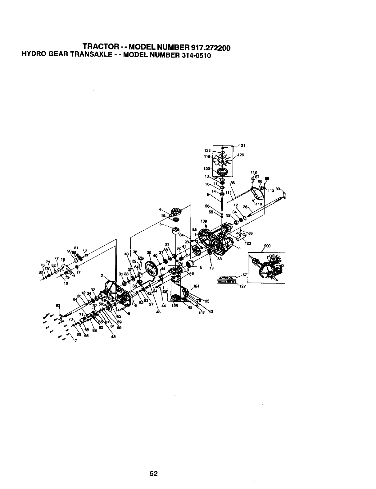
TRACTOR - - MODEL NUMBER 917.272200
HYDRO GEAR TRANSAXLE - - MODEL NUMBER 314-0510
79
73
81
107
52
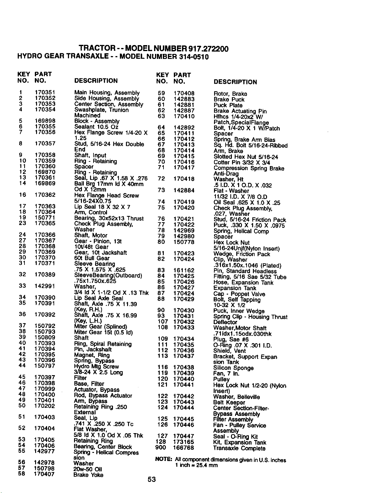
TRACTOR -- MODEL NUMBER 917.272200
HYDROGEARTRANSAXLE- - MODEL NUMBER 314-0510
KEY PART KEY PART
NO. NO. DESCRIPTION NO. NO.
1 170351 Main Housing, Assembly 59 170408
2 170352 Side Housing, Assembly 60 142883
3 170353 Center Section, Assembly 61 142881
4 170354 Swashplate, Trunion 62 142887
Machined 63 170410
5 169898 Block - Assembly
6 170355 Sealant 10.50z 64 142892
7 170356 Hex Flange Screw 1/4-20 X 65 170411
1.25 66 170412
8 170357 Stud, 5/16-24 Hex Double 67 t70413
End 68 170414
9 170358 Shaft, Input 69 170415
10 170359 Ring - Retaining 70 170416
1t 170360 Spacer 71 170417
12 169870 Ring - Retaining
13 170361 Sea], Lip .67 X 1.58 X .276 72 170418
14 169869 Ball Brg 17mm Id X 40ram
Od X 12mm 73 142884
16 170362 Hex Flange Head Screw
5/16-24X0.75 74 170419
17 170363 Lip Seal 18 X 32 X 7 75 170420
18 170364 Arm, Control
19 150771 Bearing, 30x52x13 Thrust 76 170421
23 170365 Check Plug Assembly, 77 170422
Washer 78 142969
24 170366 Shaft, Motor 79 142980
27 170367 Gear - Pinion, 13t 80 150778
28 170368 t 01/48t Gear
29 170369 Gear, 101 Jack.shaft 61 170423
30 170370 601 Bull Gear 82 170424
31 170371 Sleeve Bearing
.76 X 1.575 X .625 83 161162
32 170389 SleeveBearing(Outboard) 84 170425
.75x1,750x.625 85 170426
33 142991 Washer, 86 170427
3/4 Id X 1-1/20d X .13 Thk 87 170424
34 170390 Lip Seal Axle Seal 88 170429
35 170391 Shaft, Axle .75 X 11.39
_Key, R.H.) 90 170430
36 170392 Shaft, Axle .75 X 16.99 93 170431
(Kay, LH.) 107 170432
37 150792 Miter Liaer (Splinad) 108 170433
38 150793 Miter Gear 15t (0.5 Id)
39 150809 Shaft 109 170434
40 170393 Ring, Spiral Retaining 111 170435
41 t70394 Pin, Jackshaft 112 170436
42 170395 Magnet, Ring 113 170437
43 170396 Spnng, Bypass
44 150797 Hydro Mtg Screw 116 170438
3/8-24 X 2.5 Long 119 170439
45 170397 Filter 120 170440
46 170398 Base, Filter 121 170441
47 170999 Actuator, Bypass
48 170400 Rod, Bypass Actuator 122 170442
49 170401 Arm, Bypass 123 170443
50 170202 Retaining Ring .250 124 170444
External
51 170403 Seal, Lip 125 170445
.741 X .250 X .250 Tc 126 170446
52 170404 Flat Washer,
518 Id X 1.00d X .05 Thk 127 170447
53 170405 Retaining Ring 128 173165
54 170406 Bearing, Center Block 900 166768
55 142977 Spdng - Helical Compres
sion
56 142978 Washer
57 150798 20w-50 Oil
58 170407 Brake Yoke
53
DESCRIPTION
Rotor, Brake
Brake Puck
Puck Plate
Brake Actuating Pin
Hfhca 1/4-20x2 W/
Patch,SpecialFlange
Bolt, 1/4-20 X 1 W/Patch
Spacer
Spring, Brake Arm Bias
Sq. Hd. Bolt5/16-24-Ribbed
Arm, Brake
Slotted Hex Nut 5/16-24
Cotter Pin 3/32 X 3/4
CompressionSpringBrake
Anti-Drag
Washer, Ht
.5 I.D. X 10.D. X .032
Flat oWasher
11/32 I.D. X 7/80.D
Oil Seal .625 X t.0 X .25
Chock Plug Assembly,
.027, Washer
Stud, 5/16-24 FrictionPack
Puck, .330 X 1.50 X .0975
Spring, Helical Comp
Spacer
Hex Lock Nut
5/16-24Unjf(Nylon Insert)
Wedge, FrictionPack
Clip,Washer
.316xl.50x.1046 (Plated)
Pin, Standard Headless
Fitting, 5/16 Saa 5/32 Tube
Hose, ExpansionTank
Expansion Tank
Cap - Poppet Valve
Bolt, Self Tapping
10-32 X 1/2
Puck, Inner Wedge
SpringClip - HousingThrust
Deflector
Washer,Motor Shaft
.71idx1.15odx.030thk
Plug, Sae #6
O-Ring .07 X .301 I.D.
Shield, Vent
Bracket, Support Expan
sion Tank
S_ic,on Sponge
Fan, 7 In.
Pulley
Hex Lock Nut 1/2-20 (Nylon
Insert)
Washer, Belleville
Belt Keeper
Center Section-Filtar-
Bypass Assembly
Filter Assembly
Fan - PulleyService
Assembly
Seal - O-Ring Kit
Kit, ExpansionTank
Transaxle Complete
NOTE: All component dimensionsgiven in U.S. inches
1 inch = 25.4 mm
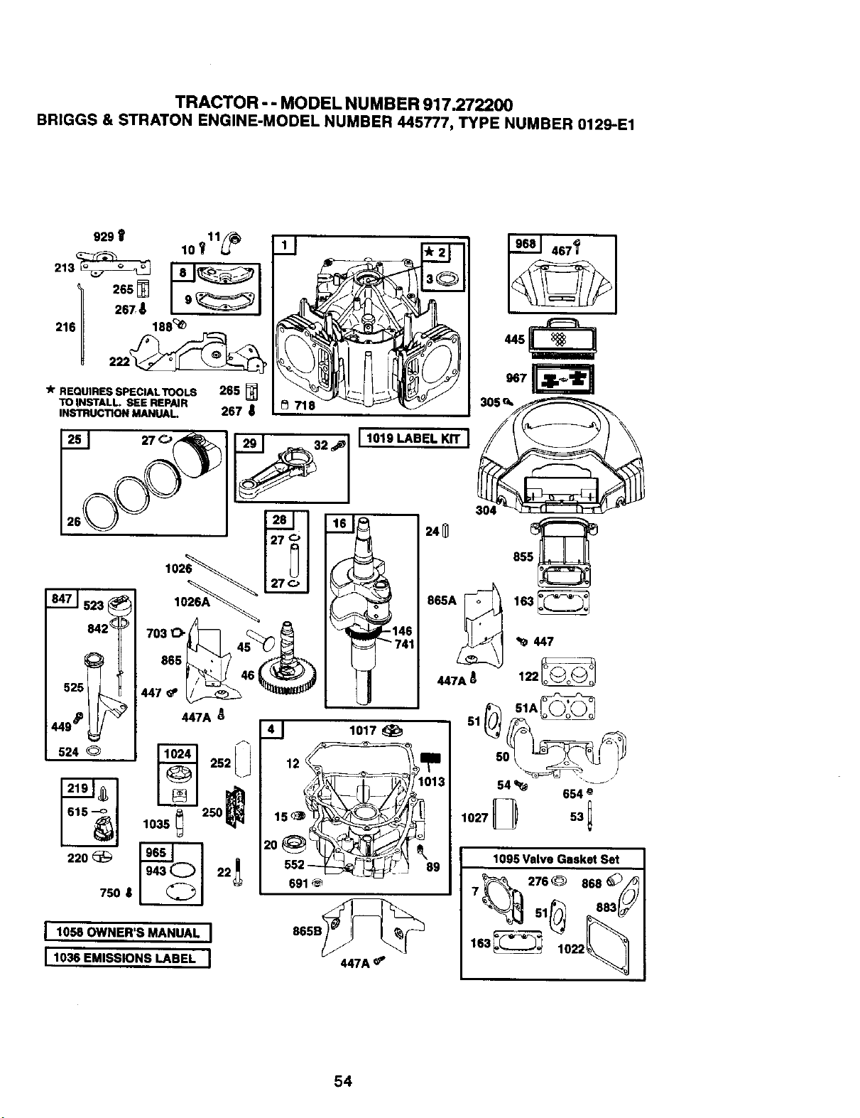
TRACTOR - - MODEL NUMBER 917.272200
BRIGGS & STRATON ENGINE-MODEL NUMBER 445777, TYPE NUMBER 0129-E1
265_ m
216 188'_
__-J_J 304 _r'r-_ I r_-_-_,
26 102___ 24_ 5_85
t842_ 70_4_ _ "_1461 .447
525 _ 147_' _ "_,mm._- 447A_ 122_
449_ _ 447A
524 Q _] 252[ i
D
250 _
1035
220 _ _--_ 22 I_
750 8
51A_
I lo. Ow.E.'S.A.UA,I
I1036 EMISSIONS LABEL I
1o17
691
865B_
447A
54 _ 654 _
1027 D 53 1
1095 Valve Gasket Set
7 _ 276 _ 868
51
163_
54
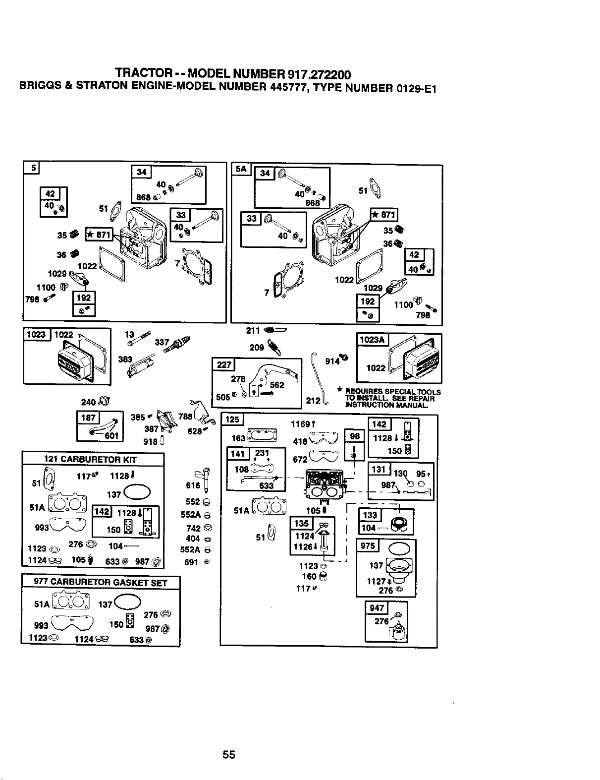
TRACTOR - - MODEL NUMBER 917.272200
BR|GGS & STRATON ENGINE-MODEL NUMBER 445777, TYPE NUMBER 0129-.E1
1022
_-_=7._ °,_ lO2,
\
387 _<_ 628" 163_------_ 418_--_-_
918 J_
121CARBURETOR KIT _231 I 672_ I _ 11131 _
1123_ 276@ 104_ 552A6
691 1123_L_ - 13"'7_ I
1124_ los_ s33_ 987_
_o_ "==__ I
977 CARBURETOR GASKET SET 117 e
51A_ 1370 _ 947"_""
993 _ 150 L'-'J 987 @
1123_ 1124 _' 633@
55
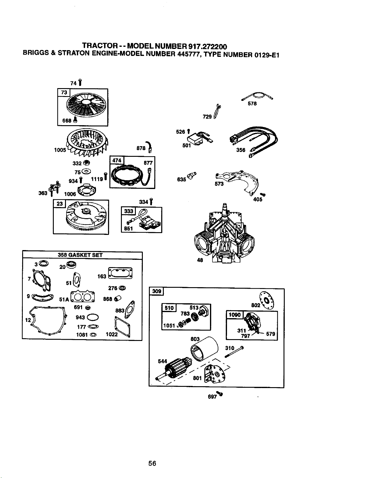
TRACTOR -- MODEL NUMBER917.272200
BRIGGS& STRATONENGINE-MODELNUMBER445777,TYPENUMBER0129-E1
74V
358 GASKET SET
3_ 20_
276
9_ 51A_ 868_ _
_2_ _, 943C)
_(_1_ 1022_
729 _ 578
63s_
4O5
48
579
56
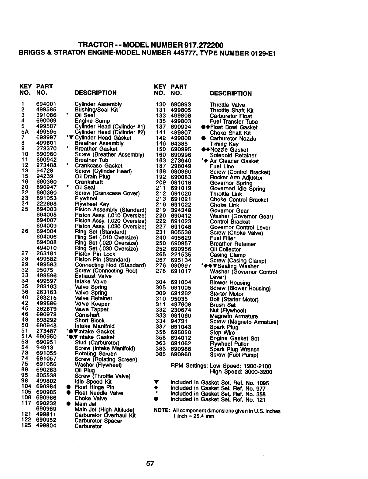
TRACTOR - -MODEL NUMBER 917.272200
BRIGGS& STRATONENGINE-MODELNUMBER445777,TYPENUMBER0129-E1
KEY PART KEY PART
NO. NO. DESCRIPTION NO. NO. DESCRIPTION
1 694001 CylinderAssembly 130 690993 Throtlle Valve
2 499585 Bushing/Seal Kit 131 499805 Throttle Shaft Kit
3 391086 Oil Seal 133 499806 Carburetor Float
4 690069 En._ine Sump 135 499803 Fuel Transfer Tube
5 499587 CylinderHead (Cylinder#1) 137 690994 Q.Float Bowl Gasket
5A 499595 CylinderHead (Cylinder#2) 141 499807 Choke Shaft Kit
7 693997 *VCylinder Head Gasket 142 499808 • CarburetorNozzle
6 499601 Breather Assembly 146 94386 Timing Key
9 273370 Breather Gasket 150 690995 €,Nozzle Gasket
10 690960 Screw (BreatherAssembly) 160 690996 Solenoid Retainer
11 690942 BreatherTub 163 273640 *4, Air Cleaner Gasket
12 273488 Crankcase Gasket 187 298049 Fuel Line
13 94728 Screw (CylinderHead) 188 690960 Screw (ControlBracket)
15 94239 Oil DrainPlug 192 690083 RockerArm Adjustor
16 690360 Crankshaft 209 691018 Governor Spring
20 690947 * Oil Seal 211 691019 Governed Idle Spdng
22 690360 Screw (CrankcaseCover) 212 691020 Throttle Link
23 691053 Flywheel 213 691021 Choke Control Bracket
24 222698 Flywheel Key 216 691022 Choke Link
25 694003 Piston Assembly(Standard) 219 394348 Govemor Gear
694005 PistonAssy.(.010 Oversize) 220 690412 Washer (Govemor Gear)
694007 PistonAssy.(.020 Oversize) 222 691023 Control Bracket
694009 PistonAssy.(.030 Oversize) 227 691048 Governor Control Lever
26 694004 Ring Set (Standard) 231 805538 Screw (Choke Valve)
694006 Ring Set (.010 Oversize) 240 495629 Fuel Filter
694006 Ring Set (.020 Oversize) 250 690957 Breather Retainer
494010 Ring Set (.030 Oversize) 252 690956 Oil Collector
27 263181 Piston Pin Lock 265 221535
Casing Clamp
28 499582 Piston Pin (Standard) 267 695134 Screw (CasingClamp)
29 499583 Connecting Rod (Standard) 276 690997 *4,<_VSealing Washer
32 95076 Screw (ConnectingRod) 278 691017 Washer (GovernorControl
33 499596 Exhaust Valve Lever)
34 499597 Intake Valve 304 691004 Blower Housing
35 263163 Valve Spring 305 691005 Screw(BiowerHousing)
36 263163 Valve Spring 309 691262 Starter Motor
40 263216 Valve Retainer 310 95035 Bolt(Starter Motor)
42 499586 Valve Keeper 311 497608 Brush Set
45 262679 Valve Tappet 332 230674 Nut (Flywheel)
46 690978 Camshaft 333 691060 Magneto Armature
48 693292 Short Block 334 94731 Screw (Magneto Armature)
50 69094:8 Intake Manifold 337 691043 Spark Plug
51 273487 *•,Intake Gasket 356 695050 Stop Wire
51A 690950 *•,Intake Gasket 358 694012 Engine Gasket Set
53 690951 Stud (Carburetor) 363 691062 Flywheel Puller
54 94913 Screw (Intake Manifold) 363 690966 Spe,rk P_UgWrench
73 691055 RotatingScreen 385 690960 Screw (Fuel Pump)
74 691057 Screw (RotatingScreen)
75 691056 Washer (Flywheel) RPM Settings:Low Speed: 1900.2100
High Speed: 3000-320089 690283 Oil Plug
95 805538 Screw (ThroffieValve)
98 499802 Idle Speed Kit • Included in Gasket Set, Ref. No. 1095
104 690984 • Float Hinge Pin 4_ IncludedIn Gasket Set, Ref. No. 977
105 690985 • Float Needle Valve * Included in Gasket Set, Ref. No. 358
108 690986 Choke Valve • Included in Gasket Set, Ref. No. 121
1t 7 690232 • Main Jet
690969 Main Jet (High Altitude) NOTE: AllcomponentdimensionsgiveninU.S.inches
121 499811 CarburetorOverhaul Kit 1 Inch= 25.4 mm
122 690952 Carburetor Spacer
125 499804 Carburetor
57
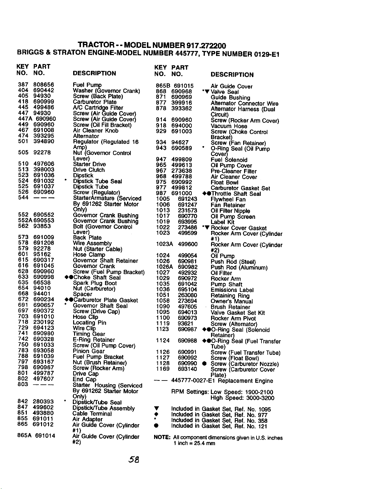
TRACTOR -- MODEL NUMBER917.272200
BRIGGS& STRATONENGINE-MODELNUMBER445777,TYPENUMBER0129-E1
KEY PART KEY PART
NO. NO. DESCRIPTION NO. NO. DESCRIPTION
387 808656 Fuel Pump 865B 691015
404 690442 Washer (Governor Crank) 868 690968
405 94930 Screw (Back Plate) 871 690969
418 690999 Carburetor Plate 877 399916
445 499486 A/C Cartridge Filter 878 393362
447 94930 Screw (Air Guide Cover)
447A 690960 Screw (Air Guide Cover) 914 690960
449 690960 Screw (Oil Fill Bracket) 918 694000
467 691008 Air Cleaner Knob 929 691003
474 393295 Alternator
501 394890 Regulator (Regulated 16 934 94627
Amp) 943 690589
505 92278 Nut (Govemor Control
Lever) 947 499809
510 497606 Starter Drive 965 499613
513 398003 DdveClutch 967 273638
523 691036 Dipstick 968 499788
524 691032 Dipstick Tube Seal 975 690992
525 691037 Dipstick Tube 977 499812
526 690960 Screw (Regulator) 987 691000
544 StarterArmature (Serviced 1005 691243
By 691262 Starter Motor 1006 691247
Only) 1013 231573
552 690552 Governor Crank Bushing 1017 690770
552A690553 Govemor Crank Bushing 1019 693995
562 93853 Bolt (Governor ContrOl 1022 273486
Lever) 1023 499599
573 691009 Back Plate
578 691208 Wire Assembly 1023A 499600
579 92278 Nut (Starter Cable)
601 95162 Hose Clamp 1024 499054
615 690317 Governor Shaft Retainer 1026 690981
616 691045 Govemor Crank 1026A 690982
628 690960 Screw (Fuel Pump Bracket) 1027 492932
633 690898 •OChoke Shall Seal 1029 690972
635 66538 Spark Plug Boot 1035 691042
654 94010 Nut (Carburetor) 1036 695104
668 94401 Spacer 1051 263080
672 690234 •OCarburetor Prate Gasket 1058 273694
691 690657 Governor Shaft Seal t090 497605
697 690372 Screw (Drive Cap) t095 694013
703 691010 Hose Clip 1100 690973
718 230192 Locating Pin 111g 93621
729 694123 Wire Clip
741 690980 Timing Gear
742 690328 E-Ring Retainer
750 691033 Screw (Oil Pump Cover)
783 693058 Pinion Gear
788 691039 Fuel Pump Bracket
797 693167 Nut (Brush Retainer)
798 890967 Screw (Rocker Arm)
801 499787 Drive Cap
802 497607 End Cap
803 ---- Starter Housing (Serviced
By 691262 Starter Motor
Only)
842 280393 Dipstick/Tube Seal
847 499602 Dipstick/Tube Assembly
851 493880 Cable Terminal
855 691011 Air Adapter
865 591012 Air Guide Cover (Cylinder
#1)
865A 691014 Air Guide Cover (Cylinder
#2)
Air GuideCover
*V Valve Seal
Guide Bushing
AlternatorConnectorWire
AlternatorHarness (Dual
Circuit)
Screw(RockerArm Cover)
Vacuum Hose
Screw (Choke Control
Bracket)
Screw (Fan Retainer)
O-Ring Seal (Oil Pump
Cover)
Fuel Solenoid
Oil Pump Cover
Pre-CleanerFilter
Air Cleaner Cover
Float Bowl
CarburetorGasket Set
• OThrottle Shaft Seal
Flywheel Fan
Fan Retainer
Oil FilterNipple
Oil Pump Screen
Label Kit
*V Rocker Cover Gasket
RockerArm Cover(Cylinder
#1)
RockerArm Cover(Cylinder
#2)
Oil Pump
Push Rod (Steel,)
Push Rod (Aluminum)
OilFilter
RockerArm
Pump Shaft
EmissionsLabel
Retaining Ring
Owner's Manual
Brush Retainer
Valve Gasket Set Kit
RockerArm Pivot
Screw (Alternator)
1123 690987 <_OO-Ring Seal (Solenoid
Retainer)
1124 690988 <_OO-Ring Seal (Fuel Transfer
Tube)
1t 26 690991 Screw (Fuel Transfer Tube)
1t 27 690992 Screw (Float Bowl)
1128 690990 • Screw (Carburetor Nozzle)
1169 693140 Screw (Carburetor Cover
Plate)
---- 445777-0027-E1 Replacement Engine
RPM Settings:Low Speed: 1900-2100
High Speed: 3000-3200
• Includedin Gasket Set, Ref. No. 1095
• Included in Gasket Set, Rat. No. 977
Includedin Gasket Set, Ref. No. 358
• Includedin Gasket Set, Ref. No. 121
NOTE: All componentdimensions givenin U,S. inches
1 inch = 25.4 mm
58

SUGGESTED GUIDE FOR SIGHTING SLOPES FOR SAFE OPERATION
_r _
SIGHTING
GUIDE
ONLY RIDE UP AND DOWN HILL,
NOT ACROSS HILL
I_ Operate your Tractor up and down the face of slopes (not I
I
greater than 15°), never across the face. Make turns gradu-
I
ally to prevent tipping or loss of control. Exercise extreme
caution when changing direction on slopes.

Forrepar of major _ al:Ol_'_ncesin your own home...
no rnaP,er who made it, no matter who sotdit!
1-800-4-MY-H OME%_n_ (_o_n_ht
(1-800-469-4663)
www.letlrl,¢Ol_
Tobringinpoducts suchasvacuun's,lawnequipmenta_d electr_ics
for repair,callfor the IocatJonofyournearestSears Parts & Repair Center
1-800-488-1222 A,v_ _=r_
WWW.INIQI1Lconl
Forl_hereplacement parts, acces_des and owner's marx_ls
bhat you reed to d_it-yourself, call 8ears PartsDIrect*!
1-800-366-PART 6_ -11pxncsr.
(1-800-366-7278) 7daysaweek
www.mar_€om I partsdlrect
To purchase or inquire about a SearsServk:eAgreerne_:
1-800-827-6655
7 a.m,- 5 p.rn.CST,Mort.- Sat.
P_aperussv_oderepara_adont_
yparaordmarplezasooner_ga adordcilio:
1488-6U-HOG_P"
(1-888.784-6427)
HomeCentralJ
AuCanadapourserviceenrranais:
1-877-LE-FOYER"
(1-8-/7-533-6937)
Q I_ T_ I m T_ M _olll'i, RollbuekI1_ _.
O Sears, Roebuck and Co. ® Matte Re_ I w M,_t= de F_xk:a de8earn, RoebuckandCo.
172113 12.22.99 SV Printedin U.S.A.


