Thank you for selecting and buying V-TAC product. V-TAC will serve you the best. Please read these
instructions carefully before starting the installation and keep this manual handy for future reference.
If you have any another query, please contact our dealer or local vendor from whom you have
purchased the product. They are trained and ready to serve you at the best. The warranty is valid for
2 years from the date of purchase. The warranty does not apply to damage caused by incorrect
installation or abnormal wear and tear. The company gives no warranty against damage to any
surface due to incorrect removal and installation of the product. The products are suitable for 10-12
Hours Daily operation. Usage of product for 24 Hours a day would void the warranty. This product is
warranted for manufacturing defects only.
ATTENTION!
Do not look directly at LED light beam. Product can only be supplied by rated voltage or voltage
within the range provided. It's forbidden to use the product with damaged protective cover. Product
must not be used in unfavorable conditions, e.g. dust, water, moisture, vibrations, explosive air
atmosphere, fumes, or chemical fumes, etc. In the area of strong electromagnetic interference, the
functioning of the product may be disrupted.
USAGE GUIDELINES / MAINTENANCE
Any maintenance work must be performed when the power supply is cut off and the product has
cooled down. Clean only with soft and dry cloths. Do not use chemical detergents. Do not cover the
product. Ensure free air access. Product may heat up to a higher temperature.
WARNING:
• Please make sure to turn off the power before starting
the installation.
• Installation must be performed by a certified person.
• The light source of this luminaire is not replaceable,
when the light source reaches its end of life the whole
luminaire should be replaced.
• For Indoor use only
• If the external flexible cable or cord of this luminaire is
damaged, it shall be exclusively replaced by the
manufacturer or his service agent or a similar qualified
person in order to avoid a hazard.
• Method of attachment of the cable or cord such that
any replacement can only be made by the manufacturer,
his service agent or similar qualifed person.
Caution, risk of
electric shock.
'This product contains a light source of energy efficiency class <F>', where <F> shall be
replaced by the energy efficiency class of the contained light source.
This marking indicates that this
product should not be disposed
of with other household wastes.
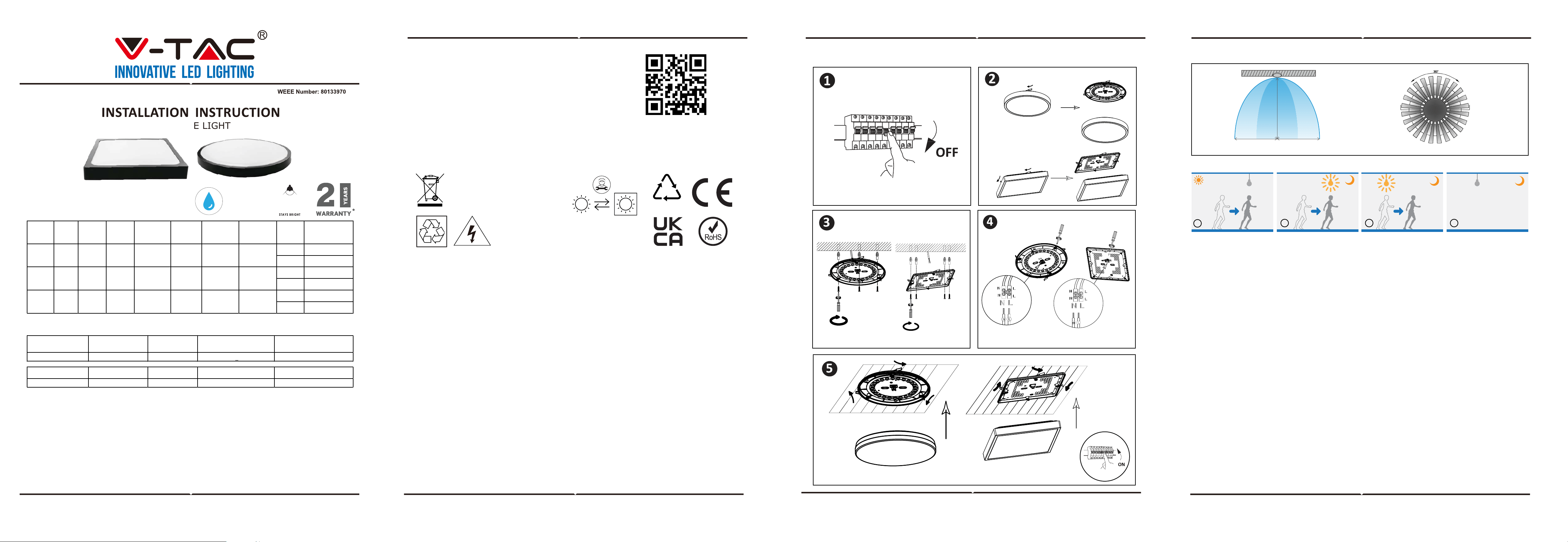
INSTALLATION INSTRUCTION:
• Switch Off the Power Before Starting the Installation.
• Twist and remove the cover (Ref Image Part 2)
• Drill a hole in the ceiling to fix the light using screws (Ref Image Part 3)
• Connect the wires (Ref Image Part 4) before fixing the light using screws on the ceiling.
• Twist and lock the cover to the light (Ref Image Part 5)
• Switch ON the power and test the light.
MOUNTING:
Read the manual before mounting. Mounting should be performed by a qualified electrician. Exercise
caution. Product has a protective contact /terminal. Failure to connect the protective lead may lead to
electric shock. Mounting diagram: see pictures. Check for proper mechanical fastening and connection
to electrical power prior to first use.
TECHNICAL DATA:
SENSOR TECHNICAL DATA:
IN CASE OF ANY QUERY/ISSUE WITH THE PRODUCT, PLEASE REACH OUT TO US AT: SUPPORT@V-TAC.EU
FOR MORE PRODUCTS RANGE, INQUIRY PLEASE CONTACT OUR DISTRIBUTOR OR NEAREST DEALERS.
V-TAC EUROPE LTD. BULGARIA, PLOVDIV 4000, BUL.L.KARAVELOW 9B
Replaceable light
source by a
professional
TEST METHOD
Start Up Phase
1. The microwave lamp shall be installed at a height of 3M above the ground to ensure that the front induction antenna is horizontally
downward, i.e. in the direction of the ground;
2. Power on;
3. The microwave induction module is connected to the power supply. At this time, the module continuously outputs the high level for self
inspection for 4S. After the self inspection is completed, the module continuously outputs the low level and enters the working state.
Intelligent Control Stage:
1. When someone enters the microwave induction coverage range (2-4 meters can be customized), the microwave induction module
outputs a high level;
2. If someone is active in the microwave coverage area, the induction module always outputs a high level;
3. When a person leaves the microwave coverage range for 1 minute, the induction module outputs a low level
Test precautions and special instructions:
1. During the test (especially when the technician tests the sample, the product must be placed on the table top and the antenna surface
must be upward), the person must be at least 1m away from the table top.
2. When the light is off, the radar silence time of 1 second is required to be triggered again;
3. During the test, try to eliminate external interference factors, such as the movement of the machine and people or the movement of
the partition wall, and prevent low-frequency resonance, false alarm and misjudgment;
4. The delay time refers to the time interval from the start to the end of the last sensing signal, and the countdown after the person
leaves the sensing area;
5. Traditional products are not suitable for long-distance applications installed in a narrow space
6. The above delay time, distance and photosensitive parameters can be appropriately modified according to customer requirements.
Supplementary Note:
Warning: If signal output port (IFI / IFQ) is sensitive to ESD (electrostatic damage), contact with high electrostatic area or power area
may cause irreversible damage to the radar module
Warning: If the lamps have been matched (not limited to brands and models) in the development stage, please do not replace other
unmatched equipment (including but not limited to power supply and lamps) during use. If the equipment is replaced without authoriza-
tion and there is any abnormality, our company will not be responsible.
Suggestion: It is recommended to use qualified DC stabilized power supply, i.e. DC stabilized power supply with output voltage, current
and ripple coefficient up to standard, otherwise the stability of this product will be affected and some abnormalities may occur, such as
false alarm, no induction, circulation and self startup.
Matters Needing Attention
1. Avoid installing metal accessories or shells, which will shield the microwave and affect the effect;
2. The antenna surface shall be protected from high current circuit coverage, which may cause interference;
3. The photosensitive position shall be protected from opaque objects, which will change the photosensitive intensity;
4. The recommended installation distance of the sensor is greater than 1.5m.
INSTALLATION DIAGRAM:
LED DOME LIGHT
IP44
RATING
22
PAP
SPHERE
360°
MODEL WATTS LUMENS
BEAM
ANGLE
BODY TYPE
TOTAL
CURRENT
LUMEN PER
WATTS
INPUT
POWER
SHAPE
DIMENSION
(LxWxH)
ROUND ⌀225x60mm
SQUARE 225x225x60mm
ROUND ⌀295x65mm
SQUARE 295x295x65mm
ROUND
⌀
420x65mm
SQUARE 420x420x65mm
100lm/w
AC:220-240,
50/60Hz
VT-8630 30W 3000LM
Sphere
360°
PP+PMMA 140mA
100lm/w
AC:220-240,
50/60Hz
VT-8624 24W 2400LM
Sphere
360°
PP+PMMA 170mA 100lm/w
AC:220-240,
50/60Hz
VT-8618 18W 1800LM
Sphere
360°
PP+PMMA 100mA
SENSOR INFORMATION
2-4m (Radius)
2-4m 2-4m
2-4m (Radius)
Height of Installation: 3m
Detection Distance: Max. 8m
Height 3m
1. When the ambient light is bright enough, even if a moving object is detected, the lamp will not automatically light up
2. When the ambient light is lower than the preset photosensitive threshold, the light will automatically light up when the sensor detects
a moving object
3. When the sensor cannot detect the moving object after the moving object leaves, it will enter the delay time and keep the light on
4. After the moving object leaves and after the preset delay time, the lamp will automatically turn off
1
2 3 4
SENSOR USAGE
DIMENSION INPUT POWER STANDBY POWER
WORKING FREQUENCY OF
RADAR MODULE
INSTALLATION HEIGHT
16mm*16mm*2.2mm DC: 5V 5V @ < 12mA
5.8GHz+75Mhz 3m
DETECTION RADIUS INITIALIZATION TIME HOLDUP TIME WORKING TEMPERATURE AMBIENT LIGHT THRESHOLD
2-4m 4 sec 1 Min -20°C ~ 85°C 30Lux
INTRODUCTION & WARRANTY
MULTI-LANGUAGE
MANUAL QR CODE
Please scan the QR code
to access the manual in
multiple languages.
LED LED