Loading ...
Loading ...
Loading ...
12
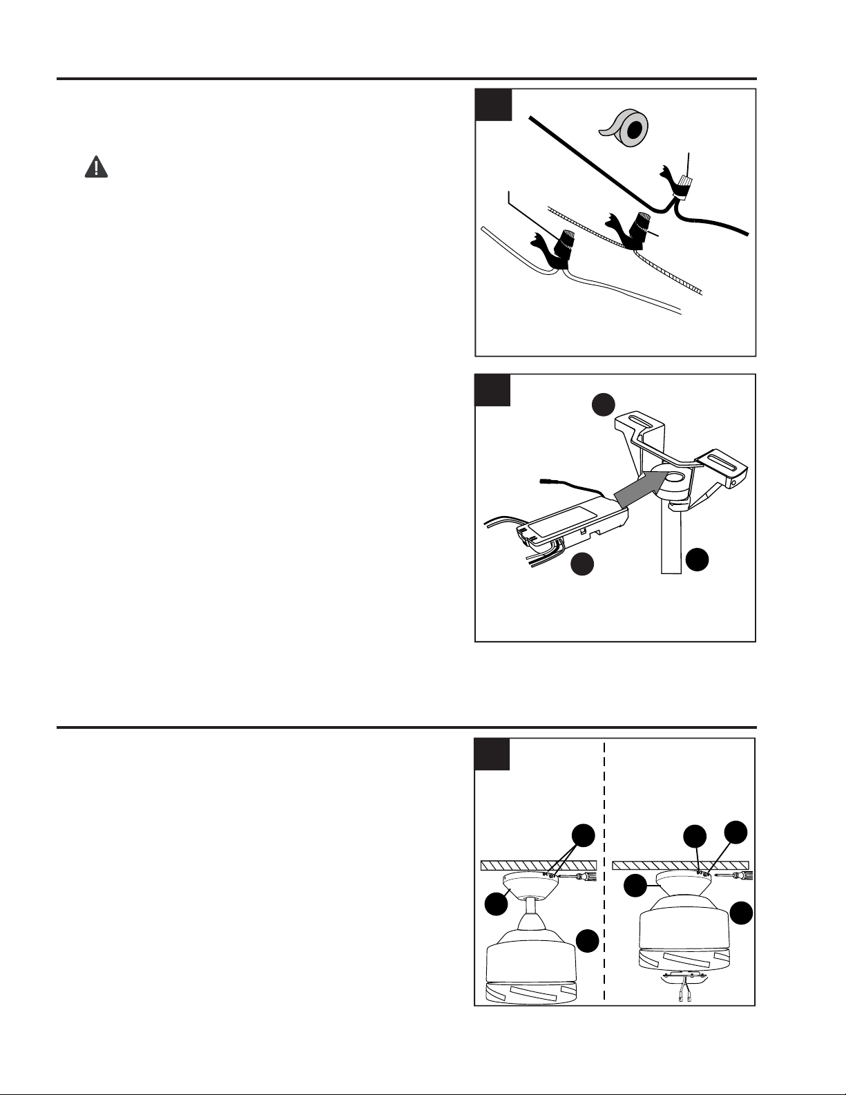
Wrap electrical tape (not included) around each
individual wire connector from remote pack (G);
wrap down to the wire.
WARNING: Make sure no bare wire or wire
strands are visible after making connections. Place
GREEN and WHITE connections on opposite side
of the outlet box from the BLACK and BLUE (if
applicable) connections.
2.
2
WIRING
Wire
Connector
Wire
Connector
Wire
Connector
3
Gently slide remote control receiver (P) flat-side up
into mounting bracket (A). Turn spliced/taped wires
upward and gently push wires and wire connectors
from remote pack (G) into outlet box. Let antenna
from remote control receiver (P) hang to the side.
NOTE: The remote control included with this fan
meets the following requirements:
a. Not for use with solid state fans.
b. Electrical rating: 120V / 60 Hz;
motor amps:1.25 MAX.
3.
Antenna
P
A
FINAL INSTALLATION
C
1.
Temporarily lift canopy (F) to mounting bracket (A) to
determine which two canopy mounting screws (B) in
mounting bracket (A) align with slotted holes in
canopy (F) and partially loosen these two canopy
mounting screws (B). Remove the other two canopy
mounting screws (B). Now, lift canopy (F) to mounting
bracket (A) again, aligning slotted holes in canopy (F)
with loosened canopy mounting screws (B) in
mounting bracket (A). Twist canopy (F) clockwise to
lock. Re-insert the two canopy mounting screws (B)
that were just removed and tighten all canopy
mounting screws (B) securely.
1
I
F
Downrod
Option
Closemount
Option
B
F
B
B
I
Loading ...
Loading ...
Loading ...