Loading ...
Loading ...
Loading ...
NOTE: Make certain the cables are seated properly in the 2.
roller guides. See Fig. 3-18.
Close the flange keepers to secure the chute assembly
to the chute base. The flange keepers will click into place
when properly secure. See Fig. 3-20.
Figure 3-18
2.
Secure the handle by tightening the plastic knob located
on both the left and right sides of the handle. Remove
and discard any rubber bands, if present. They are for
packaging purposes only.
ChuteAssembly
1. Position the chute assembly over the base. See Fig. 3-19.
/
Figure 3-19
,_ .J
Figure 3-20
NOTE: If the flange keepers will not easily click into place,
use the palm of your hand to apply swift, firm pressure to
the back of each.
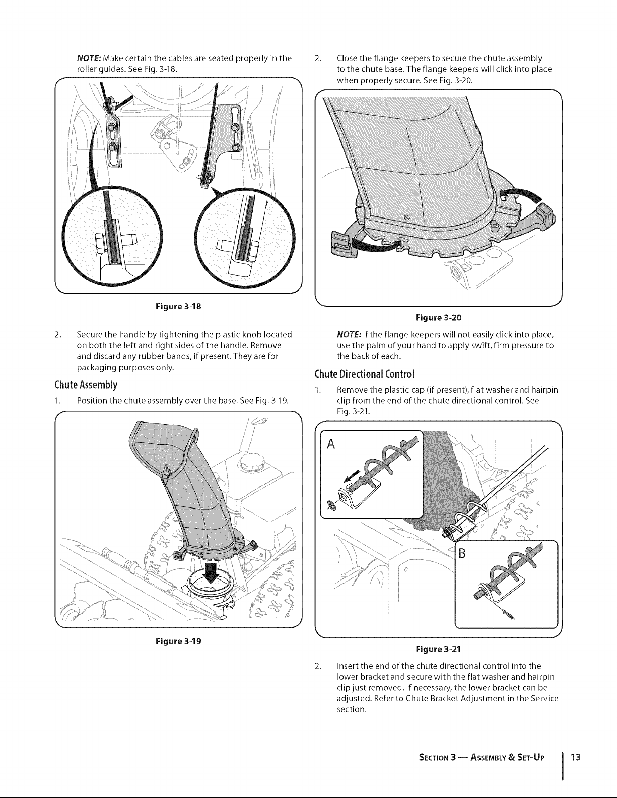
ChuteDirectional Control
Remove the plastic cap (if present), flat washer and hairpin
clip from the end of the chute directional control. See
Fig. 3-21.
B
2.
Figure 3-21
Insert the end of the chute directional control into the
lower bracket and secure with the flat washer and hairpin
clip just removed. If necessary, the lower bracket can be
adjusted. Refer to Chute Bracket Adjustment in the Service
section.
SECTION3 = ASSEMBLY& SET-UP 13
Loading ...
Loading ...
Loading ...