Reproduction of this manual, in whole or in part, by any means, is prohibited.
Version 1.0 / April 2021
Professional Broadcast
PTZ Joystick Controller
OPERATION GUIDE
CCU-IP

Section 1:
Product Details and Specs
Section 2:
Quick Start / Wiring
Section 3:
Buttons and Congurations
Section 4:
Installation and Setup
Section 5:
Network Conguration
Section 6:
FAQ
Section 7:
Questions / Support / Outro
Table of Content
CCU-IP

3
WARNING
To prevent damage which may result in fire or electric shock hazard, do not expose this appliance to rain or moisture.
1. Be sure to use only the standard adapter that is specied in the specication sheet. Using any other adapter could cause re,
electrical shock, or damage to the product.
2. Incorrectly connecting the power supply or replacing battery may cause explosion,cause excessive heat or re
3. Securely plug the power cord into the power receptacle. Insecure connection may cause re.
4. Do not place conductive objects (e.g. screw drivers, coins, metal items, etc.) or containers lled with water on top of the camera.
Doing so may cause personal injury due to re, electric shock, or falling objects.
Continue on Next Page
CAUTION:
RISK OF ELECTRIC SHOCK.
DO NOT OPEN.
CAUTION:
TO REDUCE THE RISK OF ELECTRIC SHOCK, DO NOT REMOVE COVER (OR BACK)
NO USER SERVICEABLE PARTS INSIDE. REFER SERVICING TO QUALIFIED SERVICE PERSONNEL.
WARNING
This symbol indicates that dangerous
voltage consisting a risk of electric shock
is present within this unit.
PRECAUTION
This exclamation point symbol is intended to alert
the user to the presence of important operating and
maintenance (servicing) instructions in the literature
accompanying the appliance.

4
5. Do not install the unit in humid, dusty, or sooty locations. Doing so may cause re or electric shock
6. If any unusual smells or smoke come from the unit, stop using the product. Immediately disconnect the power source
and contact the service center. Continued use in such a condition may cause re or electric shock.
7. If this product fails to operate normally, contact the nearest service center. Never disassemble or modify this product in any way.
8. When cleaning, do not spray water directly onto parts of the product. Doing so may cause re or electric shock.
Please read this Operation Guide before installing and using the camera & retain this copy for your reference.
1. Always follow the instructions in the operations guide when applying power. Fire and equipment damage can occur if power is
applied incorrectly. For the correct power supply,refer to the specications page.
2. Do not use camera if fumes, smoke or a strange odor is emitted from the camera, or if it seems not functional correctly.
Disconnect the power source immediately and consult with your supplier.
3. Do not use the camera in extreme environments where high temperatures or high humidity exists. Use the camera under
conditions where temperatures are between 32°F ~ 104°F, and humidity is below 90%.
4. If installed close to a TV, radio transmitter, magnet, electric motor transformer or audio speakers the magnetic eld generated
may interfere with or distort the image.
5. Try to avoid uorescent light reections, unstable light conditions, direct pointing toward the sun. Use caution when operating the camera
in the vicinity of spotlights or other bright lights and light reecting objects.
6. To prevent damage, do not drop the camera or subject it to strong shock or vibration.
Warning continues
PRECAUTION
5
SECTION: 1
• Capable of controlling up to 7 cameras via VISCA over UDP/TCP and Sony VISCA over UDP and Sony VISCA RS232/422.
• Onscreen LCD for accurate setting adjustments
• LED Silicone buttons for precision and prolong use
• Precise AIDA Function layout for full control of our PTZ Lineup
• PoE Compatible for single-wire runs
• Ergonomic design for comfort and ease of use
• Plug and play design for setup in minutes
FEATURES
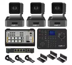
CCU-IP OUTPUT DIAGRAM
6
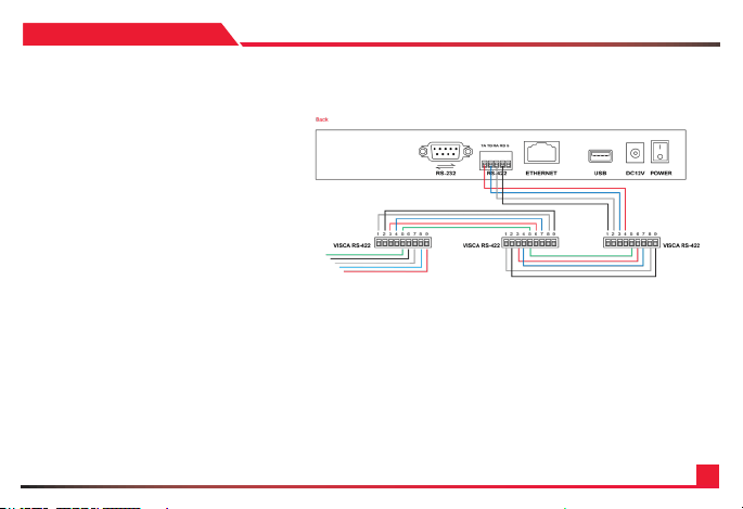
Using RS422 requires the specic connection labeled
above. In order to chain more cameras, please go
out of the rst camera with the following wiring and
into the next with the guide above. Once complete,
please select protocol VISCA, and address and
baudrate to set the camera.
Tip:
Don’t forget to set the ID address for each camera.
SECTION: 2
RS422 Connection:
Ra < --------- > TXD IN-
Rb < --------- > TXD IN+
Ta < --------- > RXD IN-
Tb < --------- > RXD IN+
Joystick Camera#1 Camera#2
TXD OUT+ < --------- > RXD IN+
TXD OUT- < --------- > RXD IN-
RXD OUT+ < --------- > TXD IN+
RXD OUT- < --------- > TXD IN-
< --------- >

7
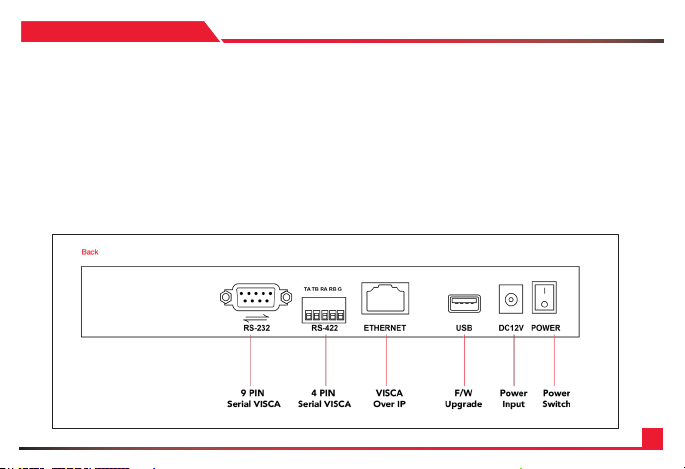
For RS232 connection, please connect a RS232 Visca
cable (comes free with any AIDA PTZ Purchase) and
connect the controller to the in port of the RS232 on
the back of the camera. Any more cameras require
additional RS232 mini-din cables, or CBL-RJ45 cables
(purchased separately) for longer distance. Once
complete, please select protocol VISCA, and address
and baudrate to set the camera.
Tip: Don’t forget to set the ID address for each
camera.
SECTION: 2
RS232 Connection:
8
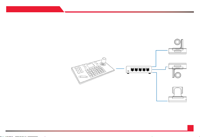
To connect, please make sure the cameras
are on the same switch as the CCU-IP. The
controller comes default with a static IP
address of 192.168.1.108. If you want to change
this, enter the camera menu by pressing
the SETUP button, and look for network
attributes. Here you can adjust the IP, or
change the controller to DHCP mode.
To connect to the camera, please have the
IP addresses of the camera on hand, and
add a network device. From there, plug in
the camera number, Sony VISCA protocol,
and IP address and port (52381 by default)
After conrming, the LCD screen will let
you know if its connected or not.
SECTION: 2
RJ45 Connection:

9
SECTION: 3

10
SECTION: 3
WHITE BALANCE
EXPOSURE
BRIGHTNESS
White Balance Mode – Toggle through the applicable white balance modes the camera
has to offer.
White balance Auto – Instantly switch to Auto white balance mode.
Exposure Mode – Toggle through the applicable exposure modes the camera has to offer.
Exposure Auto – Instantly switch to Auto exposure mode.
Brightness up – instantly increase the brightness of the picture by an interval.
Brightness down – instantly decrease the brightness of the picture by an interval.
1: RGAIN/BGAIN +/- - Instantly change to manual white balance mode and change
either the red or blue gain. By clicking the knob, you will select the next selection
(default Rgain)
2: PT SPEED – Controls the pan tilt speed of the camera by intervals.
3. IRIS– instantly switch to manual auto exposure mode and adjust the opening and
closing of the iris.
4. ZOOM SPEED – changes the speed at which the camera zooms by intervals.
5. CAMERA SELECTION – used to select each camera set by the user. The button that
is lit up is the currently selected camera.
11
SECTION: 3
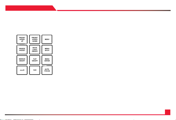
1: PRESET SPEED UP - Increase the speed at which the camera moves between presets
by intervals
2: PRESET SPEED DOWN – Decrease the speed at which the camera moves between
presets by intervals
3. MENU– Open and close the Camera menu
4. FREEZE PRESET – toggle on and off the freeze preset command, which freezes the
image inbetween preset usage
5. BACKLIGHT ON/OFF – Toggle on and off the backlight of the camera
6: MENU BACK - Used to go back in submenus of the camera
7: MIRROR ON/OFF – Toggle on and off to mirror the image of the camera
8. FLIP ON/OFF– Toggle on and off to ip the image of the camera (if the camera allows it)
9. MENU ENTER – Used to enter a submenu of the camera (if the camera allows it)
10. NEAR – Instantly switches to manual focus mode and initiates the focusing of the lens to
nearby objects in intervals.
11. FAR– Instantly switches to manual focus mode and initiates the focusing of the lens to
further objects in intervals.
12. AUTO FOCUS – Instantly switch back to auto focus so the PTZ auto focus on its own.
12
SECTION: 3
1: SET UP - Enter the menu of the controller
2: HOME – Instantly recalls the PTZ to its home position
3. SET– Press to initiate a saving of a preset
4. RESET – Press to initiate a deletion of a preset
5. ESC – Used to go back in the camera control menu
6: ENTER - Used to enter a sub menu of the controller
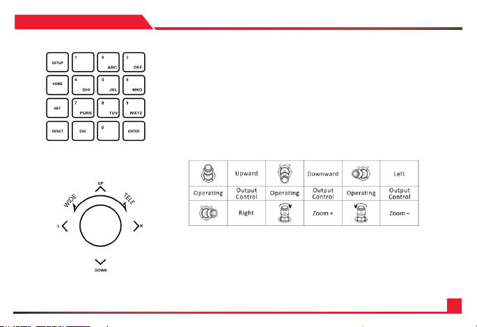
7: KEYPAD – U sed to recall and create presets.
1: JOYSTICK - Used to pan tilt, and zoom the camera, as well as
navigate in PTZ and Controller menus.
2: ENTER – Used to enter submenus in the controller

13
• CAMERA : Using the keypad, select which number you would like to set the camera
• PROTOCOL : Using the joystick, cycle through the various protocols and choose the
correct one.
• IP ADD : Enter the IP address of the camera you want to control
• PORT : Enter the VISCA port number of the camera (default for AIDA PTZ: 52381)
power frequency in order to minimize video icker.
• CAMERA : Using the keypad, select which number you would like to set the camera
• PROTOCOL : Using the joystick, cycle through the various protocols and choose
the correct one
• ADDRESS : Enter the cameras physical address ID that you want to control
• BAUDR ATE : Select the baudrate the camera is currently using
Aa: Once you press enter, you will be prompted back to the same submenu.
Press escape to go back
Aa: Once you press enter, you will be prompted back to the same submenu.
Press escape to go back
SECTION: 3
Camera : -
Protocol :
IP Add :
Port :
Camera : -
Protocol :
Address :
Baudrate :
ADD NETWORK DEVICE
ADD ANALOG DEVICE
Network Device
Network Device

14
• 1/7 : This sub menu allows you to see the protocol, address, and other important
information of each camera.
• DHCP : Sets the camera to DHCP, automatically taking a IP address assigned by a
router
• STATIC IP : Allows you to manually set the cameras IP address.
i: IP: Using the keypad, manually set the keyboards IP address
ii: Gateway: Using the keypad, manually set the keyboards gateway address
iii: Mask: Using the keypad, manually set the keyboards gateway mask
Aa: Once complete, the controller will restart.
Aa: Once complete, the controller will restart.
SECTION: 3
DEVICE LIST
NETWORK ATTRIBUTE
Camera :
Protocol :
IP Add. :
Port :
Protocol :
Address :
Baudrate :
De vice Lis t
1/7
IP : -. . .
Gateway :
Mask :
Static

15
Toggle on or off the button sounds of the keyboard.
Toggle on or off the button sounds of the keyboard.
Factory reset the camera
Enter this submenu to get the controllers information
a. Software Version: Displays the software version of the controller
b. Hardware Version: Displays the hardware version of the controller
c. Web Version: Displays the web version of the controller
d. Gateway: Displays the current gateway of the controller
e. Subnet Mask: displays the current subnet mask of the controller.
Aa: Once complete, the controller will restart.
SECTION: 3
BACKLIGHT
BUTTON TONE
FACTORY RESET
SYSTEM INFO
Software Version :
Hardware Version :
Web Version :
Gateway :
Sub Netmask :
System Info
1. Add Network Device
2. Add Serial Device
3. Device List : Inquire
4. Network Attribute : Static
5. Backlight : ON
6. Button Tone : ON
7. Factory Reset
8. System Info
9. VISCA Response : Enable
Keyboard Setting

16
SECTION: 4
1. Ensure that all connections to the controller and network
are fastened. Please power the controller and allow it ample
time for its rst boot up.
2. Once the controller has booted up, please preset the
[SETUP] button on the camera to enter the menu.
3. In the controller menu, please select Add Network
Device.
4. In the Camera section, please use the keypad on the
controller to assign a number to this device. This will be
used to recall it with the CAM buttons. Press enter once set.
5. Next, select the correct protocol for the camera. Cycle
through the options. If you are using any AIDA PTZ with
a network connection, please select SONY VISCA(UDP).
Once set, press enter.
6. Under IP, using the keypad enter the correct IP address
of the camera. Make sure that they are on the same network
for this to work. Press enter once done.
7. For Port, please enter the VISCA port of the camera. For
our PTZ’s, the default is 52381. You can nd it in your PTZ
camera settings as well. Press enter when done.
8. It will say successfully at the bottom if it worked. Press
ESC to exit the menus, and press the designated CAM
button to see if you can control the camera.
9. Repeat the steps to add more cameras.
ADDING A NETWORK DEVICE (IP)

17
SECTION: 4
1. Ensure that all connections to the controller and network are
fastened. Please power the controller and allow it ample time
for its rst boot up.
2. Once the controller has booted up, please preset the [SETUP]
button on the camera to enter the menu.
3. In the controller menu, please select Add Analog Device.
4. In the Camera section, please us the keypad on the controller
to assign a number to this device. This will be used to recall it
with the CAM buttons. Press enter once set.
5. Next, select the correct protocol for the camera. Cycle
through the options. Once set, press enter.
6. Under Address, enter the cameras set address ID using the
keypad. Once complete, press enter.
7. For Baudrate, cycle through the selection of baudrates
and match your PTZ’s. Once complete, press enter. It will say
successfully at the bottom if it worked. Press ESC to exit the
menus, and press the designated CAM button to see if you
can control the camera. You might have to hold the joystick
enter button down to enter serial mode if you have not already
done it.
8. Repeat the steps to add more cameras.
ADDING A SERIAL DEVICE
18
SECTION: 5
CONNECTING TO THE WEB PORTAL
The CCU-IP will natively come at the IP address of 192 .168 .1.10 8.
Please note that if you are not able to access the web browser and are getting errors,
recheck your network and make sure that the CCU-IP’s IP address matches.
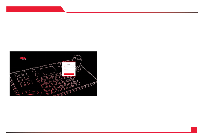
1. Log into your main browser and attempt to connect to the IP
address of the CCU-IP. Natively the IP address is 192.168.1.108.
You should get an image like this:.
2. Log in using the following default credentials:
Username: admin
Pas s wo rd: 111111
Note
If you forget your credentials, you can manually default the
credentials by factory resetting the board via the controller
setup menu.
19
SECTION: 5
USING THE WEB PORTAL
The web portal has a variety of tools created to help
optimize your setup experience with the CCU-IP fast
and efciently.
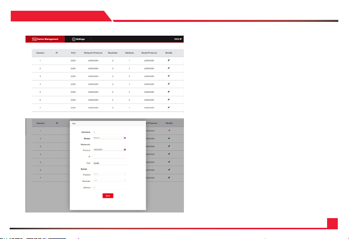
On the main screen, you are able to modify each camera’s
setting slot.
Set up instructions using the web portal are the same as
adding an IP camera via the LED screen.
Please follow those directions in the previous Section 4.
20
SECTION: 5
SETTINGS TABS
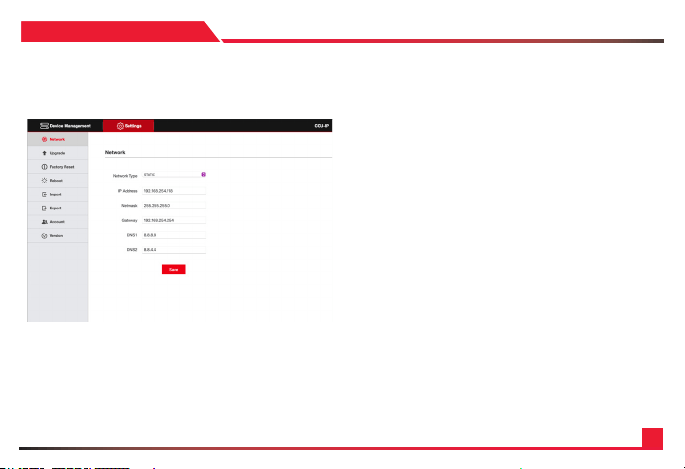
Under the settings tab you will nd a couple of optimizable settings.
1. Network: Adjust the CCU-IP’s network settings, such as
DCHP or Static IP addresses, as well as changing the Static
IP address settings.
2. Upgrade: Used for potential future rmware upgrades.
As of now there is no new rmware released.
3.
Factory Reset: Clicking the reset button will factory reset the
controller. Do note that if you changed your IP address, the
CCU-IP will factory default back to IP Address 192.168.1.108.
4. Reboot: Clicking the restart button will power cycle the
controller. No settings will be lost.
5.
Import: Allows you to import any saved AIDA CCU-IP preset
les. This will change all of your settings.
6.
Export: Allows you to export your current AIDA CCU-IP
settings into a preset le, which can later be imported to the
same or other controllers.
7. Account: Create multiple user accounts to access the controller.
8. Version: Displays the current CCU-IP version numbers.

21
SECTION: 6
• My device is not powering on:
Please make sure that you are using the given power supply, or PoE+ power supply that is recommended.
• My device is stuck initializing:
Please remove the power source and restart it again. If the problem persists, please contact our support team via email or phone.
• My device is connected to the network, but I can’t open the web interface:
Please ensure you are connecting to the correct IP address. Also double check to see if your CCU-IP is on the same IP address as your
cameras and network. Please refer to video references on our Youtube Channel if you are unsure how to do that.
• My device is connected to my camera, but I can’t control: Please ensure that the connections are fastened. Follow the specic steps
mentioned in adding IP or Analog cameras. If the problem still persists, please contact our support team via email or phone.
• I don’t remember my password to the web interface:
Please factory reset your device through the LCD screen on the controller. This will reset the all saved settings, including network,
cameras and account info.
• My third-party camera isn’t being controlled:
Please ensure the correct settings for your third-party camera is correct. The above process is only tested on AIDA Imaging cameras, so
third-party cameras may have a different settings which will need to be tweaked on the controller. It would be best to reach out to our
support team for more info on how to connect.
• Some controls aren’t working:
Please note that all functions on the keyboard controller are made for the most up to date PTZ rmware for our cameras. IF your AIDA
Imaging PTZ camera is not up to date, there will be functions that will not work on your controller. Also note that all third-party cameras
functions may not be fully supported, so use at your own risk.
FAQ

22
*Specication are subject to change without notice.
SECTION: 7
SYNCHRONIZATION
Control Protocol VISCA, VISCA over IP
Control Interface RS-232 / RS-422 / RJ-45
Number of Camera Supported 7
Dimensions 12.625 x 7 x 4.25 (W x D x H)
Weight 4lbs ( Net Weight )
Power PoE / 12VDC

23
SECTION: 7
Visit us:
www.aidaimaging.com/support
E-mail us:
suppor[email protected]
Give us a Call:
Toll Free: 844.631.8367 | Tel: 909.333.7421
Operating Hours: Mon-Fri | 8:00am – 5:00pm PST

24
Disposal of Old Appliances
1. When this crossed-out wheel bin symbol is attached to a product it means the product is covered by the European Directive 2002/96/EC.
2. All electrical and electronic products should be disposed of separately form the municipal waste stream in accordance to laws designated by the government or the local authorities.
3. The correct disposal of your old appliance will help prevent potential negative consequences for the environment and human health.
4. For more detailed information about disposal of your old appliance, please contact your city ofce, waste disposal service or the shop where you purchased the product.
This equipment has been tested and found to comply with the limits for a Class A digital device, pursuant to part 15 of the FCC Rules. These limits are designed to provide reasonable protection against
harmful inter ference when the equipment is operated in a commercial environment. This equipment generates, uses, and can radiate radio frequency energy and, if not installed and used in accordance with
the instruction manual, may cause harmful interference to radio communications. Operation of this equipment in a residential area is likely to cause harmful inter reference in which case the user will be required
to correc t the interference at his own expense.