238-51012-00L REV 6/20
A Spanish language version of these instructions is available by contacting
the company listed on the rating plate.
La versión española de estas instrucciones se puede obtener al scribirle a la
fábrica cuyo nombre aparece en la placa de especificaciones.
For your family’s comfort, safety and convenience, we recommend this
water heater be installed and serviced by a plumbing professional.
GAS-FIRED WATER HEATER
Installation & Operation Instruction Manual For
Flammable Vapor Ignition Resistant System
Equipped Water Heater
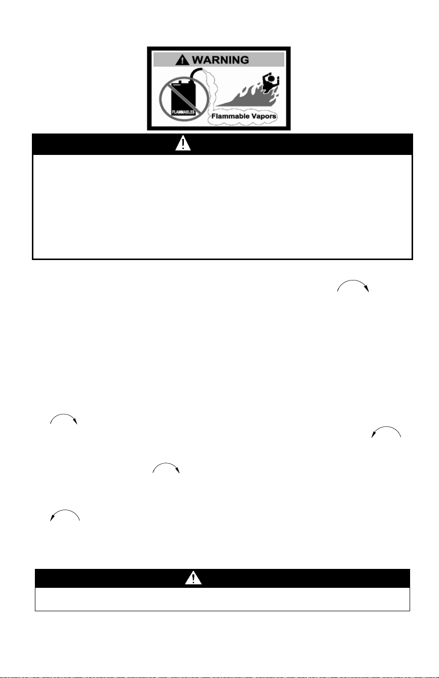
WARNING:
If the information in these instructions is not followed
exactly, a fire or explosion may result in property damage, personal
injury, or death.
– WHAT TO DO IF YOU SMELL GAS
• DO NOT try to light any appliance.
• DO NOT touch any electrical switch; DO NOT use any phone
in your building.
• Immediately call your gas supplier from a neighbor’s phone.
Follow the gas supplier’s instructions.
• If you cannot reach your gas supplier, call the fire
department.
– Installation and service must be performed by a qualified
installer, service agency, or the gas supplier.
For Your Safety
Do NOT store or use gasoline or other flammable, combustible, or
corrosive vapors and liquids in the vicinity of this our any other appliance.

2
CONGRATULATIONS!
You have purchased one of the finest water heaters on the market today!
This installation, operation and instruction manual will explain in detail
the installation and maintenance of your new Flammable Vapor Ignition
Resistant Gas Water Heater. We strongly recommend that you contact a
plumbing professional for the installation of this water heater.
We require that you carefully read this manual, as well as the enclosed
warranty, and refer to it when questions arise. If you have any specific
questions concerning your warranty, please consult the plumbing
professional from whom your water heater was purchased. For your
records we recommend that you write the model, serial number and
installation date of your water heater in the maintenance section in the
back of this manual.
This manual should be kept with the water heater.
Special Flammable Vapor Ignition Resistant System
This water heater is equipped with a Flammable Vapor Ignition Resistant
System. In the event of improper usage or storage of gasoline or other
flammable materials in the location where the water heater is installed, the
technology will resist ignition of the flammable vapors outside the confines of
the water heater.
The Flammable Vapor Ignition Resistant System features:
• Advanced Flame Arrestor Design
• Re-settable Thermal Switch to prevent burner/pilot operation with
restricted airflow
• Piezo Igniter
• Sight Window to observe operation of pilot and burner
FOR YOUR SAFETY: Activation of the Flammable Vapor Ignition Resistant
System occurs when flammable vapors are drawn into the water heater and
are combusted. If flammable vapors are detected:
• Do not try to light any appliance.
• Do not touch any electrical switch.
• Do not use any phone in your building.
• Leave the premises and immediately call the fire department from a
neighbor’s phone. Follow the fire department’s instructions.
Once the flammable vapor has been evacuated, contact your plumbing
professional or the manufacturer for further instructions. Replacement of a
Flammable Vapor Ignition Resistant System equipped water heater due to a
flammable vapor shutdown is not covered under the terms of the limited
warranty.

3
TABLE OF CONTENTS
Page
GENERAL INFORMATION ............................................................ 4
INSTALLATION ............................................................................. 5
Locating The Water Heater .................................................... 5
Minimum Clearances .............................................................. 8
Venting..................................................................................... 9
Combustion Air Supply .......................................................... 10
Water Connections ................................................................. 11
Gas Connections .................................................................... 13
GENERAL OPERATION ................................................................ 15
Lighting & Shutdown Instructions ........................................ 16
Thermostat Adjustment ......................................................... 19
Burner Flame Check ............................................................... 21
MAINTENANCE ............................................................................. 22
TROUBLESHOOTING ................................................................... 24
INSTALLATION DRAWING FOR POTABLE WATER .................. 29
PARTS DIAGRAM ......................................................................... 30
INSTALLATION INSTRUCTIONS FOR POTABLE WATER AND
SPACE HEATING .......................................................................... 31
NOTES ........................................................................................... 32
4
GENERAL INFORMATION
This gas-fired water heater is design certified by CSA International under the
applicable American National Standard, Z21.10.1 or CSA 4.1-(as indicated on the
rating plate), available from CSA International, 8501 East Pleasant Valley Road,
Cleveland, OH U.S.A. 44131-5575.
This water heater must be installed in accordance with local codes. In the absence of
local codes, it must be installed in compliance with the National Fuel Gas Code (ANSI
Z223.1-Latest Edition), or in Canada CAN/CGA B149.1 Natural Gas Installation Code
(Latest Edition) or CAN/CGA B149.2 Propane Installation Code (Latest Edition). The
warranty for this water heater is in effect only when the water heater is installed,
adjusted, and operated in accordance with these Installation and Operating
Instructions. The manufacturer will not be liable for any damage resulting from
alteration and/or failure to comply with these instructions.
This water heater is not design certified for installation in a mobile home. Such an
installation may create a hazardous condition and will nullify the warranty.
This water heater has been designed and certified for the purpose of heating
potable water. The installation and use of this water heater for any purpose
other than the heating of potable water may cause damage to the water
heater, create a hazardous condition, and nullify the warranty.
Do NOT use this appliance if any external part to the tank has been
submerged in water. You should contact a qualified service technician to
inspect the appliance and to replace any part of the control system including
the combination gas control which has been submerged in water. See the Gas
Connections section of this manual before servicing or replacing a water
heater that has had any external part to the tank submerged in water.
CAUTION
Incorrect operation of this appliance may create a hazard to life and property and
will nullify the warranty.
WARNING
Prior to connecting the gas supply line to a gas fired water heater, ensure that the
gas supply line does not have moisture/water or dirt/scale inside the gas line.
Commonly this check is done at the lowest point in the gas distribution system
prior to gas burning appliances.
DANGER
DO NOT store or use gasoline or other flammable, combustible, or corrosive
vapors and liquids in the vicinity of this or any other appliance.
IMPORTANT
Before proceeding, please inspect the water heater and components for
possible damage. DO NOT install any damaged components. If damage is
evident then please contact the supplier where the water heater was
purchased, or the manufacturer listed on the rating plate for replacement parts.

5
General Information cont.-
This water heater has been manufactured for operation at altitudes from sea level to
2000 ft (610 m) (unless otherwise specified on the water heater rating plate). For use
of this appliance at an elevation greater than 2000 ft (610 m), contact the dealer or
manufacturer listed on the rating plate for information on any necessary modification.
Incorrect operation of this appliance may create a hazard to life and property.
Make sure that you check the rating plate and combination gas control on the water
heater to be certain that the type of gas being supplied corresponds with the marking
on the rating plate and combination gas control.
A sacrificial anode is used to extend tank life. Removal of any anode, except for
inspection and/or replacement, will nullify the warranty. In areas where water is
unusually active, an odor may occur at the hot water faucet due to a reaction between
the sacrificial anode and impurities in the water. If this should happen, an alternative
anode(s) may be purchased from the supplier that installed this water heater. This will
minimize the odor while protecting the tank. Additionally, the water heater should be
flushed with appropriate dissolvers to eliminate any bacteria.
INSTALLATION
Locating The Water Heater
This water heater MUST NOT be installed in any location where gasoline or
flammable vapors are likely to be present, unless the installation is such to
eliminate the probable ignition of gasoline or flammable vapors.
Water heaters in residential garages must be installed and located, or protected, to
avoid physical damage. For other installations refer to local codes. In the absence of
local codes, the water heater must be installed in compliance with the National Fuel
Gas Code, (ANSI Z223.1- Latest Edition), or in Canada CAN/CGA B149.1 Natural Gas
Installation Code (Latest Edition) or CAN/CGA B149.2 Propane Installation Code
(Latest Edition).
The location of this water heater is of the utmost importance. Before installing this
water heater, read the installation section of these instructions. After reading these
Installation and Operation Instructions, select a location for the water heater where the
floor is level and is easily accessible to gas and water supply lines. Do NOT locate the
water heater where water lines could be subjected to freezing temperatures.
Make sure the cold water pipes are NOT located directly above the gas control
so that condensate during humid weather does NOT drip on the controls.
WARNING
Water heaters are heat producing appliances. To avoid damage or injury
there shall be no materials stored against the water heater or vent-air
intake system and proper care shall be taken to avoid unnecessary
contact (especially by children) with the water heater and vent-air intake
components. UNDER NO CIRCUMSTANCES SHOULD FLAMMABLE
MATERIALS, SUCH AS GASOLINE OR PAINT THINNER BE USED OR
STORED IN THE VICINITY OF THIS WATER HEATER, VENT-AIR
INTAKE SYSTEM OR IN ANY LOCATION FROM WHICH FUMES
COULD REACH THE WATER HEATER OR VENT-AIR INTAKE
SYSTEM.

6
Installation (Locating the Water Heater) cont.-
This water heater MUST be installed indoors out of the wind and weather.
To comply with NSF requirements this water heater is to be:
a) Sealed to the floor with sealant, in a smooth and easily cleanable way, or
b) Installed with an optional leg kit that includes legs and/or extensions that
provide a minimum clearance of 6” beneath the water heater.
Note: For California installation, this water heater must be braced, anchored, or
strapped to avoid falling or moving during an earthquake. See instructions for
correct installation procedures. Instructions may be obtained from DSA
Headquarters Office, 1102 Q Street, Suite 5100, Sacramento, CA 95811.
Water heater corrosion and component failure can be caused by the heating and
breakdown of airborne chemical vapors. Examples of some typical compounds that are
potentially corrosive are: spray can propellants, cleaning solvents, refrigerator and air
conditioning refrigerants, swimming pool chemicals, calcium and sodium chloride,
waxes and process chemicals. These materials are corrosive at very low concentration
levels with little or no odor to reveal their presence.
NOTE: Damage to the water heater caused by exposure to corrosive vapors is
NOT covered by the warranty. Do NOT operate the water heater if exposure has
or will occur. Do NOT store any potentially corrosive compounds in the vicinity
of the water heater.
WARNING
Liquefied petroleum gases/propane gases are heavier than air and will remain
at floor level if there is a leak. Basements, crawl spaces, closets and areas
below ground level will serve as pockets for accumulation of leaking gas. Before
lighting, smell all around the appliance area for gas. Be sure to smell next to
the floor.
IF YOU SMELL GAS:
• DO NOT try to light any appliance.
• DO NOT touch any electric switch; DO NOT use any telephone in your
building.
• Immediately call your gas supplier from a neighbor’s telephone. Follow the
gas supplier’s instructions.
• If you cannot reach your gas supplier, call the fire department.
DO NOT OPERATE APPLIANCE UNTIL LEAKAGE IS CORRECTED!
WARNING
DO NOT ATTEMPT TO LIGHT ANY GAS APPLIANCE IF YOU ARE NOT
CERTAIN OF THE FOLLOWING:
• Liquefied petroleum gases/propane gas and natural gas have an odorant
added by the gas supplier that aids in detection of the gas.
• Most people recognize this odor as a “sulfur” or “rotten egg” smell.
• Other conditions, such as “odorant fade” can cause the odorant to diminish
in intensity, or “fade”, and not be as readily detectable.
• If you have a diminished sense of smell or are in any way unsure of the
presence of gas, immediately contact your gas supplier from a neighbor’s
telephone.
• Gas detectors are available. Contact your gas supplier or plumbing
professional for more information.

7
Installation (Locating the Water Heater) cont.-
Proper venting practices must be considered when selecting a location for this
water heater. For exact venting specifications, please consult the Venting
section of these Installation and Operation Instructions.
This water heater must be located in an area where leakage of the tank, water
line connections, or the combination temperature and pressure relief valve will
not result in damage to the area adjacent to the water heater or to lower floors
of the structure. When such locations cannot be avoided, a suitable drain pan
must be installed under the water heater. The drain pan must have a minimum
length and width of at least 4 in (10.2 cm) greater than the diameter of the
water heater and must not restrict proper combustion air flow to the water
heater. The drain pan, as described above, can be purchased from your
plumbing professional. The drain pan must be piped to an adequate drain.
The piping must be at least 3/4 in (1.9 cm) in diameter and pitched for proper
drainage.
It is recommended that a minimum clearance of 4 in (10.2 cm) be provided on
the side of the water heater for servicing and maintenance of the combination
temperature and pressure relief valve.
8
Minimum Clearances
This installation shall allow access to the front of the water heater and
adequate clearance shall be provided for servicing and operating this water
heater. The water heater may be installed on either a combustible or non-
combustible floor. If the water heater is to be installed directly on carpeting, it
shall be installed on top of a metal or wood panel (or equivalent) extending
beyond the full width and depth of the appliance by at least 3 in (7.6 cm) in
any direction or, if the appliance is to be installed in an alcove or closet, the
entire floor shall be covered by the panel.
If the rating plate or the label on the front of the heater specifies
minimum clearances less than those listed in the below table, the water
heater may be installed in accordance with the minimum clearances
listed on the rating plate or the label on the front of the heater.
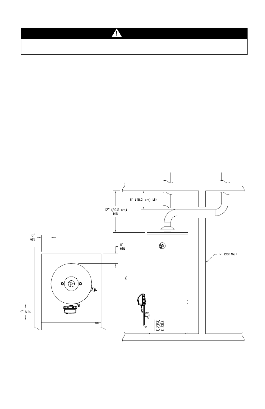
If it is necessary to install this water heater in an alcove, use the clearances
listed in Figure 1.
Figure 1
WARNING
Failure to adhere to these installation and operating instructions may
create a hazard to life and property and will nullify the warranty.

9
Venting
This water heater has been shipped with a draft diverter for which it was designed with
reference to the horizontal and vertical planes. If removed, the draft diverter must be
replaced in the same position and secured to the jacket top by which it was installed.
This water heater must be connected to a lined masonry chimney or venting system
approved by local codes or ordinances. The vent connector used to attach the draft
diverter outlet to the chimney or approved vent must be of the same diameter as the
draft diverter outlet or larger.
For proper venting in certain installations, a larger vent connector may be needed.
Consult venting tables in ANSI standard (Z223.1-or latest edition), National Fuel Gas
Code and CAN/CGA (B149.1 or B149.2-latest editions) Natural Gas and Propane
Installation Code, or local code officials for proper application for your area.
WARNING
The venting system must be installed properly following all local codes or in the
absence of local codes, the latest edition of the National Fuel Gas Code (ANSI
Z223.1- latest edition), or in Canada, The Natural Gas and Propane Installation
Code (B149.1-00 latest edition). Failure to properly install the venting system
could result in property damage, personal injury, or death.
WARNING
Carefully inspect the venting system of a replacement water heater installation
before connecting to the venting system. All joints in the vent connector must be
securely fastened with screws and fit tightly together. Inspect the venting
system for signs of deterioration (rust and perforation) and replace any sections
that are not in good condition.
The chimney must be lined and in good condition. Check to make sure the
venting system is properly sized for the water heater. If the venting system was
previously sized for another gas appliance that has been removed, the venting
system may now be too large. Refer to the latest edition of the National Fuel
Gas Code (ANSI Z223.1-latest edition), or in Canada, the Natural Gas and
Propane Installation Code (B149.1-00 latest edition) for the correct sizing of
venting systems and common venting with another gas appliance.
DO NOT vent this water heater into the venting system of another gas appliance
designed to vent under positive pressure.
The water heater should be installed as close as practical to the venting system
to minimize the vent connector length required. Refer to local codes for the
distance limitations on vent connector lengths.
At the completion of the water heater installation, the burner and venting system
must be checked for proper operation with all other commonly vented
appliances in operation. Check for spillage of flue products around the outside
relief opening of the draft hood after several minutes of operation. The flame
from a match should be drawn into the draft hood. DO NOT use the water
heater or connected equipment if spillage is detected until the problem is
corrected.
Refer to the latest edition of the National Fuel Gas Code, or in Canada, the
Natural Gas and Propane Installation Code for complete details on the
“Procedure to Be Followed to Place Equipment in Operation”.
10
Combustion Air Supply
Provide adequate air for combustion and ventilation. An insufficient supply of air will
cause recirculation of combustion products resulting in air contamination that may be
hazardous to life. Such a condition often will result in a yellow, luminous burner flame,
causing carboning or sooting of the combustion chamber, burners and flue tubes with
possible damage to the water heater.
When an exhaust fan is installed in the same room with a heater, sufficient openings
for air must be provided in the walls. Undersized openings will cause air to be drawn
into the room through the chimney, causing recirculation of combustion products.
Unconfined Spaces
In unconfined spaces in buildings, infiltration may be adequate to provide air for
combustion, ventilation, and dilution of flue gases. However, in buildings of tight
construction (heavily insulated, weather stripping, caulked, vapor barrier, etc.)
additional air may need to be provided using the methods described below.
Confined Spaces
Confined spaces are spaces defined as having less than 50 ft
3
/1,000 BTU/hr (4.8
m
3
/kW) of input.
All Air from Inside the Building: The confined space must be provided with two
permanent openings communicating directly with an additional room(s) of sufficient
volume, so that the combined volume of all spaces meets the criteria for an unconfined
space. The total input of all gas utilization equipment installed in the combined space
must be considered in making this determination. Each opening must have a minimum
free area of 1 in
2
/1000 BTU/hr (2200 mm
2
/kW) of the total input rating of all gas
utilization equipment in the confined space, but not less than 100 in
2
(0.06 m
2
). One
opening must be within 12 in (31 cm) of the top and one within 12 in (31 cm) of the
bottom of the enclosure.
WARNING
Liquefied petroleum gases/propane gas are heavier than air and will remain at
floor level if there is a leak. Basements, crawl spaces, closets and areas below
ground level will serve as pockets for accumulation of leaking gas. Before
lighting, smell all around the appliance area for gas. Be sure to smell next to
the floor.
IF YOU SMELL GAS:
• DO NOT try to light any appliance.
• DO NOT touch any electric switch; DO NOT use any telephone in your
building.
• Immediately call your gas supplier from a neighbor’s telephone. Follow the
gas supplier’s instructions.
• If you cannot reach your gas supplier, call the fire department.
DO NOT OPERATE APPLIANCE UNTIL LEAKAGE IS CORRECTED!
IMPORTANT
The flow of combustion and ventilating air must NOT be obstructed. DO NOT
block or in any way restrict jacket air inlet slots located at the bottom front of the
water heater.

11
Combustion Air Supply cont.-
All Air from Outdoors: Provide two permanent openings, one commencing within 12
in (30 cm) of the top and one commencing within 12 in (30 cm) from the bottom of the
enclosure. The openings must communicate directly or by ducts with the outdoors or
spaces (crawl or attic) that freely communicate with the outdoors.
1. When communicating with the outdoors through vertical ducts, each opening must
have a minimum free area of 1 in
2
/4000 BTU/hr (550 mm
2
/kW) of total input rating
of all equipment in the enclosure.
2. When communicating with the outdoors through horizontal ducts, each opening
must have a minimum free area of 1 in
2
/2000 BTU/hr (1100 mm
2
/kW) of total input
rating of all equipment in the enclosure.
3. When ducts are used, they must be of the same cross-sectional area as the free
area of the openings to which they connect. The minimum dimension of
rectangular air ducts cannot be less than 3 in (8 cm).
Provide one permanent opening, commencing within 12 in (30 cm) of the top of the
enclosure. The appliance must have clearance of at least 1 in (3 cm) from the sides
and back and 6 in (16 cm) from the front of the appliance. The opening must
communicate directly or by ducts with the outdoors or spaces (crawl or attic) that freely
communicate with the outdoors and has a minimum free area of the following:
1. 1 in
2
/3000 BTU/hr (700 mm
2
/kW) of the total input rating of all appliances located
in the enclosure.
2. Not less than the sum of the areas of all vent connectors in the space.
Specially Engineered Installations
The requirements noted under CONFINED SPACES above will not necessarily govern
when special engineering, approved by the authority having jurisdiction, provides an
adequate supply of air for combustion, ventilation, and dilution of flue gases.
Water Connections
Note: BEFORE PROCEEDING WITH THE INSTALLATION, CLOSE THE MAIN
WATER SUPPLY VALVE.
After shutting off the main water supply, open a faucet to relieve the water line
pressure to prevent any water from leaking out of the pipes while making the water
connections to the water heater. After the pressure has been relieved, close the faucet.
The cold-water inlet and hot-water outlet are identified on the top of the water heater.
The fittings at the cold-water inlet and hot-water outlet are dielectric waterway fittings
with 3/4 in NPT male thread. Make the proper plumbing connections between the
water heater and the plumbing system to the house. Install a shut-off valve in the cold-
water supply line.
CAUTION
If sweat fittings are to be used, DO NOT apply heat to the nipples on top of the
water heater. Sweat the tubing to the adapter before fitting the adapter to the
water connections. It is imperative that heat is not applied to the nipples
containing a plastic liner.
WARNING
FAILURE TO INSTALL AND MAINTAIN A NEW, LISTED 3/4 IN X 3/4 IN
TEMPERATURE AND PRESSURE RELIEF VALVE WILL RELEASE THE
MANUFACTURER FROM ANY CLAIM, WHICH MIGHT RESULT FROM
EXCESSIVE TEMPERATURE AND PRESSURES.

12
Installation (Water Connections) continued-
If this water heater is installed in a closed water supply system, such as the one having
a back-flow preventer in the cold-water supply, provisions shall be made to control
thermal expansion. DO NOT operate this water heater in a closed system without
provisions for controlling thermal expansion. Your water supplier or local plumbing
inspector should be contacted on how to control this situation
After installation of the water lines, open the main water supply valve and fill the water
heater. While the water heater is filling, open several hot water faucets to allow air to
escape from the water system. When a steady stream of water flows through the
faucets, close them and check all water connections for possible leaks.
NEVER OPERATE THE WATER HEATER WITHOUT FIRST BEING CERTAIN IT IS
FILLED WITH WATER.
WARNING
For protection against excessive temperatures and pressure, install temperature
and pressure protective equipment required by local codes, but not less than a
combination temperature and pressure relief valve certified by a nationally
recognized testing laboratory that maintains periodic inspection of production of
listed equipment or materials as meeting the requirements of the Standard for
Relief Valves and Automatic Gas Shutoff Devices for Hot Water Supply
Systems, ANSI Z21.22 or the Standard CAN1-4.4. Temperature and Pressure
and the Standard CAN1-4.4, Temperature, Pressure, Temperature and
Pressure Relief Valves and Vacuum Relief Valves. The combination
temperature and pressure relief valve shall be marked with a maximum set
pressure not to exceed the maximum working pressure of the water heater.
The combination temperature and pressure relief valve shall also have an
hourly rated temperature steam BTU discharge capacity not less than the hourly
rating of the water heater.
Install the combination temperature and pressure relief valve into the opening
provided and marked for this purpose on the water heater.
Note: Some models may already be equipped or supplied with a combination
temperature and pressure relief valve. Verify that the combination temperature
and pressure relief valve complies with local codes. If the combination
temperature and pressure relief valve does not comply with local codes, replace
it with one that does. Follow the installation instructions above on this page.
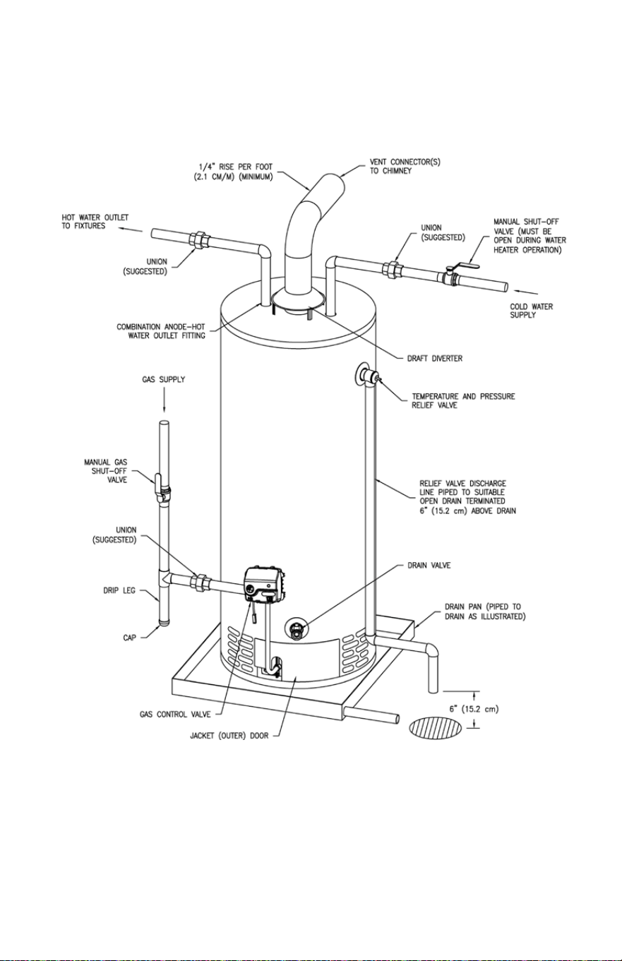
Install a discharge line so that water discharged from the combination
temperature and pressure relief valve will exit within 6 in (15.2 cm) above, or
any distance below the structural floor and cannot contact any live electrical
part. The discharge line is to be installed to allow for complete drainage of both
the combination temperature and pressure relief valve and the discharge line.
The discharge opening must not be subjected to blockage or freezing. DO NOT
thread, plug or cap the discharge line. It is recommended that a minimum
clearance of 4 in (10.2 cm) be provided on the side of the water heater for
servicing and maintenance of the combination temperature and pressure relief
valve.
DO NOT place a valve between the combination temperature and pressure
relief valve and the tank.
13
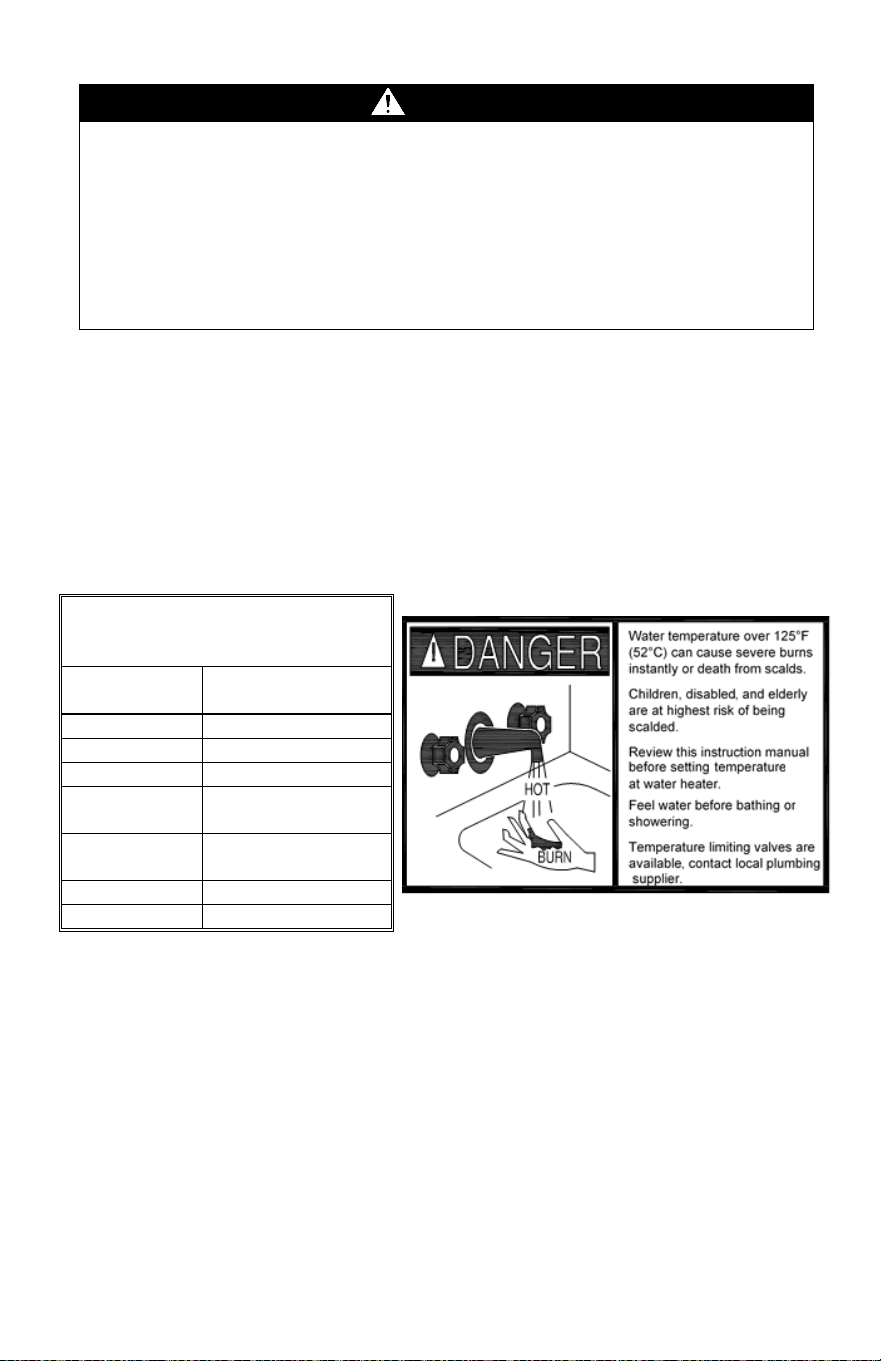
Installation (Water Connections) continued-
This water heater can deliver scalding temperature water at any faucet in the
system. Be careful whenever using hot water to avoid scalding injury. Certain
appliances such as dishwashers and automatic clothes washers may require
increased temperature water. By setting the thermostat on this water heater to
obtain the increased temperature water required by these appliances, the potential
for scald injury increases. To protect against injury, you should install an ASSE
approved mixing valve in the water system. This valve will reduce point of
discharge temperature by mixing cold and hot water in branch supply lines. Such
valves are available from the manufacturer of this water heater or a local plumbing
supplier. Please consult with a plumbing professional.
Gas Connections
The gas supply lines must meet all requirements of the National Fuel Gas Code
(ANSI Z223.1-Latest Edition), or in Canada CAN/CGA B149.1 Natural Gas
Installation Code (Latest Edition) or CAN/CGA B149.2 Propane Installation Code
(Latest Edition).
The minimum permissible gas supply pressure for the purpose of input adjustment
is 1 in (0.25 kPa) water column above the operating manifold pressure. See the
rating plate and gas valve for the manifold pressure and gas type. The maximum
permissible gas supply pressure is 14 in (3.5 kPa) water column for natural gas
and liquefied petroleum gases/propane gas.
WARNING
Hydrogen gas can be produced in an operating water heater that has not had
water drawn from the tank for a long period of time (generally two weeks or
more). HYDROGEN GAS IS EXTREMELY FLAMMABLE. To prevent the
possibility of injury under these conditions, we recommend the hot water faucet
to be open for several minutes at the kitchen sink before you use any electrical
appliance, which is connected to the hot water system. If hydrogen is present,
there will be an unusual sound such as air escaping through the pipes as hot
water begins to flow. DO NOT smoke or have open flame near the faucet at the
time it is open.
APPROXIMATE
TIME/TEMPERATURE
RELATIONSHIPS IN SCALDS
120°F (49°C)
More than 5
minutes
125°F (52°C)
1½ to 2 minutes
130°F (54°C)
About 30 seconds
135°F (57°C)
About 10 seconds
140°F (60°C)
Less than 5
seconds
145°F (63°C)
Less than 3
seconds
150°F (66°C)
About 1½ seconds
155°F (68°C)
About 1 second
14
Gas Connections cont.-
1. Connect this water heater only to the type of gas (Natural or Propane) as shown
on the rating plate. Use clean black iron pipe or equivalent material approved by
local codes and ordinances (dirt and scale from the pipe can enter the gas valve
and cause it to malfunction). The inlet gas line must have a minimum length of 3 in
(7.6 cm) drip leg (sediment trap) installed as close to the water heater’s gas valve
as possible. A ground joint union must be installed as close to the water heater as
possible in the gas supply line feeding the water heater to permit servicing of the
water heater. Compounds used on the threaded joints of the gas piping must be
resistant to the action of liquefied petroleum gases/propane gas. DO NOT apply
pipe dope to the gas valve inlet and make certain that no pipe dope has become
lodged in the inlet screen of the gas valve. Extreme care must be taken to ensure
no pipe dope enters the gas valve. Avoid excessive torque when tightening the gas
supply line to the gas valve. Excessive torque may result in cracking of the gas
valve housing and could create a gas leak. When tightening gas supply line to L.P.
control, it is recommended to hold the inlet body of the control securely with an
adequate wrench. The suggested maximum torque is 31.5 ft. lbs. (4.4 kg-m).
2. This water heater and its gas connection must be leak tested before placing the
water heater in operation. Check for gas leaks with a soap and water solution and
a brush or a commercial leak detector fluid. NEVER USE A MATCH OR OPEN
FLAME FOR TESTING!
3. While checking for leaks care must be taken to prevent solution from
contacting the electrical connections at the control. If electrical connections at the
control become wet, they must be thoroughly dried before attempting to operate
the water heater.
WARNING
The manufacturer of this water heater will not be liable for any damage or injury
caused as a result of a cracked gas inlet as a result of excessive torque.
CAUTION
The water heater and individual shutoff valve must be disconnected from the gas
supply piping system during any pressure testing of the system at test pressures
in excess of ½ psi (3.5 kPa). The water heater must be isolated from the gas
supply piping system by closing its manual shutoff valve during any pressure
testing of the gas supply system at test pressures equal to or less than ½ psi (3.5
kPa). The supply line must be capped when not connected to the water heater.
WARNING
The gas inlet pressure to the gas control must never exceed 14 in of water column
(½ psi) (3.5 kPa). The gas supply system and any pressure regulating device in
the gas line must be specified, inspected and adjusted to assure a gas supply
pressure of ½ psi (3.5 kPa) or less. Failure to do so may result in severe injury or
death.
15
GENERAL OPERATION
WARNING
Water heaters are heat producing appliances. To avoid damage or injury there
shall be no materials stored against the water heater or vent-air intake system,
and proper care shall be taken to avoid unnecessary contact (especially by
children) with the water heater and vent-air intake system. UNDER NO
CIRCUMSTANCES SHOULD FLAMMABLE MATERIALS, SUCH AS
GASOLINE OR PAINT THINNER BE USED OR STORED IN THE VICINITY OF
THIS WATER HEATER, VENT-AIR INTAKE SYSTEM OR IN ANY LOCATION
FROM WHICH FUMES COULD REACH THE WATER HEATER OR VENT-AIR
INTAKE SYSTEM.
To Fill The Water Heater
1. Close the water heater drain valve by turning the knob clockwise
.
2. Open the cold-water supply shut-off valve.
3. Open several hot water faucets to allow air to escape from the system.
4. When a steady stream of water flows from the faucets, the water heater is filled.
Close the faucets and check for water leaks at the water heater drain valve,
combination temperature and pressure relief valve and the hot and cold-water
connections.
To Drain The Water Heater
Should it become necessary to completely drain the water heater, make sure you
follow the steps below:
1. For the White Rodgers mechanical control, rotate the thermostat dial clockwise
to the lowest possible position, OR for the Honeywell and the White
Rodgers electronic controls, rotate the thermostat dial counter-clockwise
to
the lowest possible position.
2. For the White Rodgers mechanical control, partially depress and rotate the gas
control knob clockwise
to the “OFF” position.
3. Shut OFF the gas supply to the water heater.
4. Close the cold-water supply shut-off valve.
5. Open the drain valve on the water heater by turning the knob counter-clockwise
. The drain valve has threads on the end that will allow the connection of a
standard hose coupling.
6. Open a hot water faucet to allow air to enter the system.
To refill the water heater, refer to “To Fill the Water Heater.”
WARNING
Wait at least 2 minutes after this control is pressurized with gas before attempting
to light pilot and/or push igniter button. Failure to do so may result in severe injury.
16
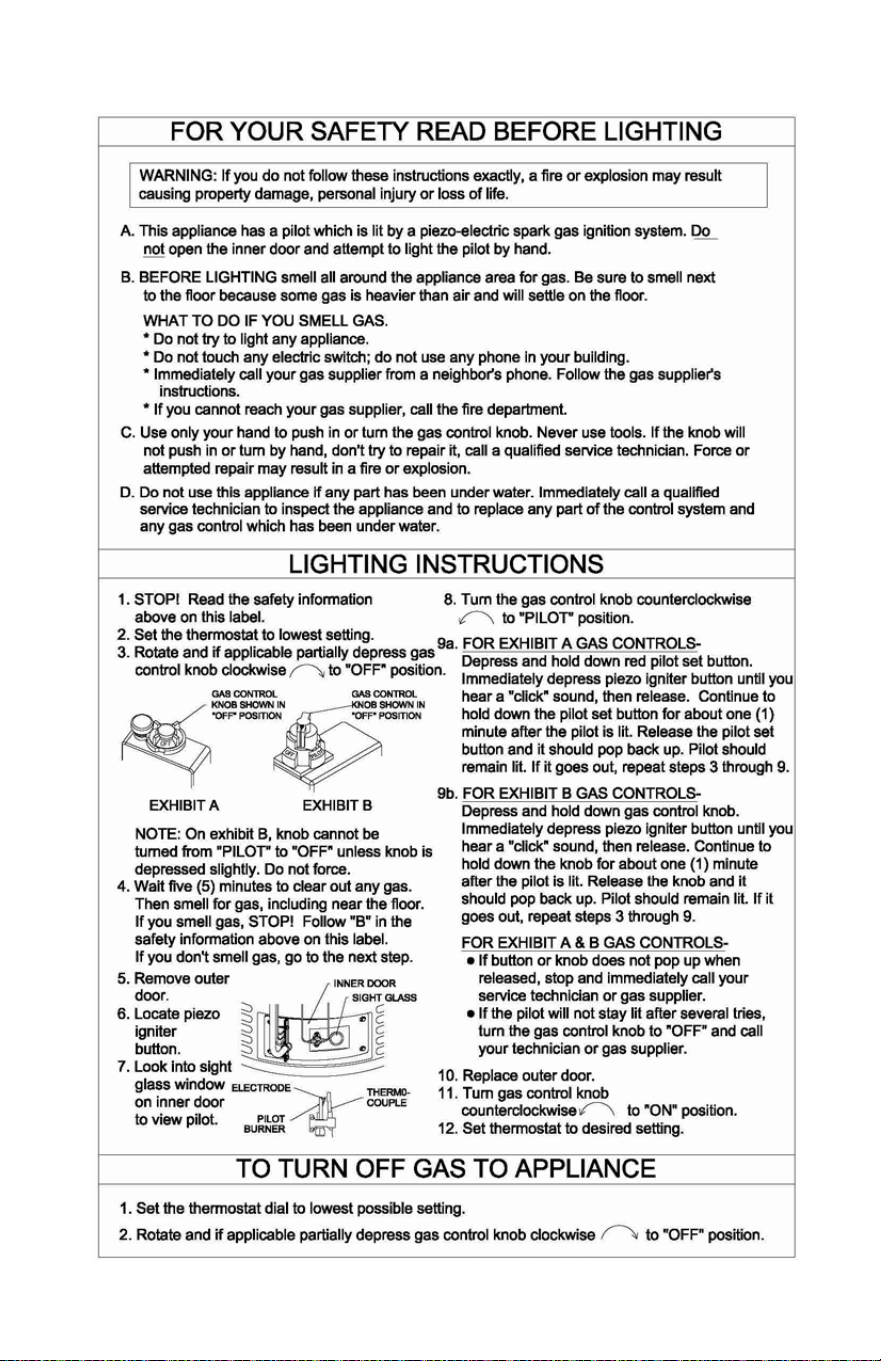
Lighting & Shutdown Instructions- White Rodgers Mechanical
Gas Control
17
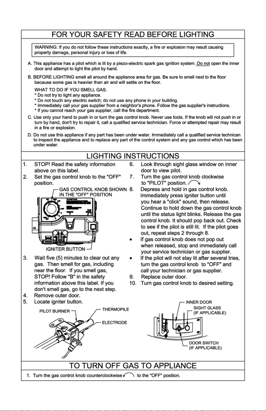
Lighting & Shutdown- White Rodgers Electronic Gas Control
18
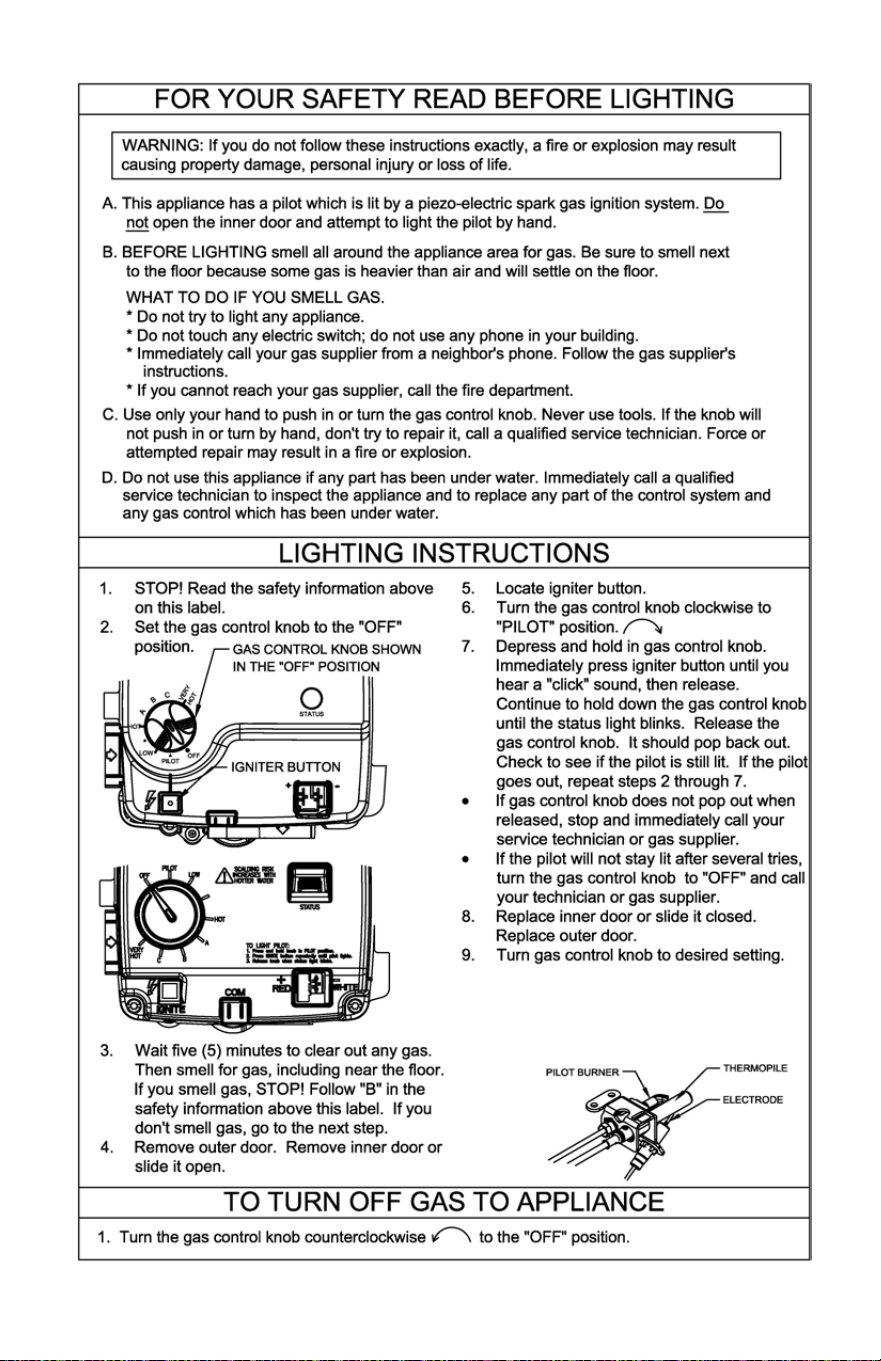
Lighting & Shutdown- Honeywell Gas Control
19
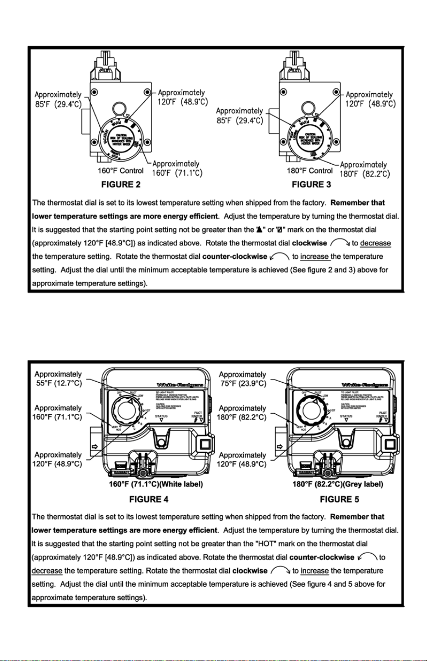
Thermostat Adjustment - White Rodgers Mechanical Gas Control
Thermostat Adjustment - White Rodgers Electronic Gas Control
20
General Operation continued-
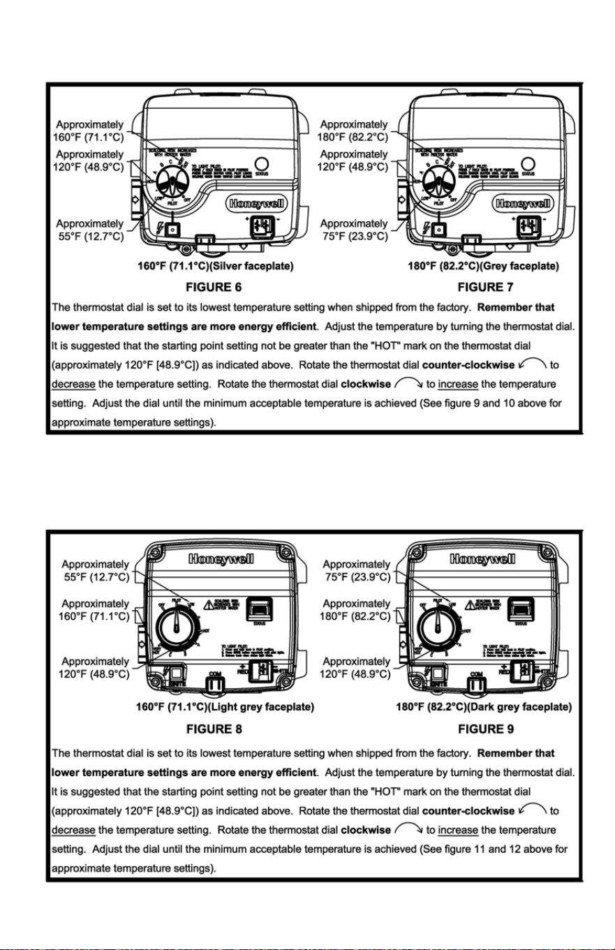
Thermostat Adjustment- Honeywell V1 Gas Control
Thermostat Adjustment- Honeywell V2 Gas Control
21
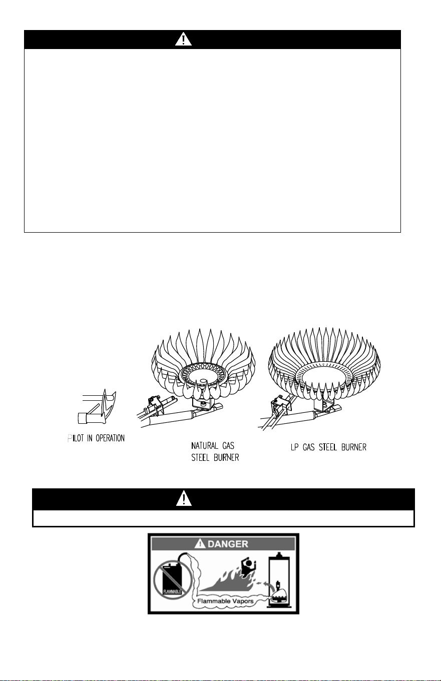
Burner Flame Checks
Steel Burner: These models are equipped with self adjusting air mixture and
do not have an adjustable air shutter (see Figure 10). At periodic intervals, a
visual check of the main burner and pilot flames should be made to determine
if they are burning properly. The main burner flame should light smoothly
from the pilot.
WARNING
Do not run out of propane gas. Damage to the water heater may occur.
WARNING
Hotter water increases the risk of scald injury. Scalding may occur within 5
seconds at a temperature setting of 140°F (60
°
C). To protect against hot
water injury, install an ASSE approved mixing valve in the water system. This
valve will reduce point of discharge temperature by mixing cold and hot water
in branch water lines. A licensed plumbing professional or local plumbing
authority should be consulted.
Note: This water heater is equipped with an energy cut out device to
prevent overheating. Should overheating occur or the gas supply fail to
shut off, turn off the manual gas control valve to the appliance and call a
qualified service technician.
Note: Whenever the water heater is filled with cold water, condensate will
form on the cool tank surface and drops of water will fall on the hot burner
and combustion chamber surfaces producing a “sizzling” noise.
Condensation is normal and does not indicate a leak. It will disappear
when the tank becomes heated.
Figure 10
22
MAINTENANCE
The following maintenance should be performed by a qualified service technician at the
minimum periodic intervals suggested below. In some installations, the maintenance
interval may be more frequent depending on the amount of use and the operating
conditions of the water heater. Regular inspection and maintenance of the water heater
and vent-air intake system will help to insure safe and reliable operation.
1. Annually check the operation of the thermostat.
2. The flow of combustion and ventilation air must NOT be restricted. Make sure
slots in jacket are open and unobstructed. Clear jacket slot openings of any dirt,
dust, or other restrictions.
3. At all times keep the water heater area clear and free from combustible materials,
gasoline and other flammable vapors and liquids.
4. Bi-annually conduct a visual check of the main and pilot burner flames to
determine that they are burning properly. See Burner Flame Check section of this
installation and operation manual. If sooting or other burner anomalies are evident,
shut down the water heater by turning off the gas per the instructions listed in this
manual or as listed on the water heater.
5. Annually remove the inner door and main burner assembly to clean orifices and
related parts of any dirt or other foreign material. Inspect the burner ports for
obstructions or debris and clean with a wire brush as needed. Wire brush and/or
vacuum clean the combustion chamber as needed to remove scale deposits and
debris. NOTE: It is imperative for proper operation of the water heater that the
inner door be replaced in the original location, making certain the resettable
thermal switch is properly connected to the gas control wire leads provided.
WARNING
Water heaters are heat producing appliances. To avoid damage or injury there
shall be no materials stored against the water heater or vent-air intake system,
and proper care shall be taken to avoid unnecessary contact (especially by
children) with the water heater and vent-air intake system.
UNDER NO CIRCUMSTANCES SHOULD FLAMMABLE MATERIALS, SUCH
AS GASOLINE OR PAINT THINNER BE USED OR STORED IN THE VICINITY
OF THIS WATER HEATER, VENT-AIR INTAKE SYSTEM OR IN ANY
LOCATION FROM WHICH FUMES COULD REACH THE WATER HEATER OR
VENT-AIR INTAKE SYSTEM.
IMPORTANT
The water heater should be inspected at a minimum annually by a qualified
service technician for damaged components and/or joints not sealed. DO
NOT operate this water heater if any part is found damaged or if any joint is
found not sealed.
WARNING
The ventilation air system may be HOT.
23
Maintenance continued-
6. At least once a year, check the combination temperature and pressure relief valve
to ensure that the valve has not become encrusted with lime. Lift the lever at the
top of the valve several times until the valve seats properly without leaking and
operates freely.
7. Monthly drain off a gallon of water to remove silt and sediment.
8. If the combination temperature and pressure relief valve on the appliance
discharges periodically, this may be due to thermal expansion in a closed water
supply system. Contact the water supplier or local plumbing inspector on how to
correct this situation. DO NOT plug the combination temperature and pressure
relief valve outlet.
9. A combination sacrificial anode rod/hot water outlet nipple has been installed to
extend tank life. The anode rod should be inspected periodically (every 2 years)
and replaced when necessary to prolong tank life. Water conditions in your area
will influence the time interval for inspection and replacement of the anode rod.
Contact the plumbing professional who installed the water heater, or the
manufacturer listed on the rating plate for anode replacement information. The use
of a water softener may increase the speed of anode consumption. More frequent
inspection of the anode is needed when using softened (or phosphate treated)
water.
10. The vent system must be inspected at least once a year to ensure against leakage
of exhaust products.
WARNING
• DO NOT operate water heater with jumpered, altered, loosely tightened or
absent controls and/or components.
• DO NOT operate water heater with replacement controls and/or components,
which are not exact duplicates or original equipment.
• Thoroughly inspect and replace, (as needed) burner inner door gasket and/or
sight window gasket any time burner inner door is removed or disturbed.
• Replace water heater if involved in flammable vapors incident.
WARNING
When lifting lever of the combination temperature and pressure relief valve, hot
water will be released under pressure. Be careful that any released water does
not result in bodily injury or property damage.
WARNING
DO NOT run out of propane gas. Damage to the water heater may occur.
WARNING
THIS WATER MAY BE HOT.

24
Troubleshooting Chart – Honeywell V1
LED Status
Control Status
Probable Cause
None (LED not
on or flashing)
Millivolt power is not
present. Light pilot.
1. Gas valve is functioning
normally.
2. Gas valve is not powered.
Light pilot.
One flash and
three second
pause
If set point knob is in
“PILOT” position, then
pilot flame is detected.
(no faults).
Gas valve is powered and
waiting for the set point knob
to be turned to a water
temperature setting. If the set
point knob is at desired
setting the thermostat is
satisfied.
LED strobe (two
quick flashes)
and three
second pause
Thermostat calling for
heat (no faults).
Water heater operating
normally.
LED on
continuously
Set point knob has
been recently turned
to the “OFF” position.
Set point knob was recently
turn to “OFF” position. Wait
until LED goes out before
attempting to relight.
Two flashes and
three second
pause
Weak pilot flame
detected. System will
reset when pilot flame
is sufficient.
1. Gas valve is functioning
normally.
2. Gas valve is not powered.
Light pilot.
Three flashes
and three
second pause
Insufficient water
heating. System will
reset.
1. Temperature sensor out of
calibration.
2. Possible short.
Four flashes and
three second
pause
Excessive tank
temperature. System
must be reset.
1. Temperature sensor out of
calibration.
2. Faulty gas valve.

25
Troubleshooting Chart – Honeywell V1 continued-
LED Status
Control Status
Probable Cause
Five flashes and
three second
pause
Temperature sensor
fault.
1. Damage to the temperature
wire.
2. Temperature sensor
resistance out of range.
3. Replace temperature sensor.
4. If temperature sensor
replacement does not correct
the problem; verify control is
not wet or physically
damaged.
5. Turn set point knob to "OFF"
position. Turn set point knob
to "PILOT" position and light
pilot.
6. Replace gas valve if five flash
error persists.
Six flashes and
three second
pause
Water leak detected
by accessory
module (some
models).
Excessive amount of water in
drain pan/water dam.
Seven flashes
and three second
pause
Gas valve electronic
fault detected.
1. Verify control is not wet or
physically damaged.
2. Turn set point knob to "OFF"
position. Turn set point knob
to "PILOT" position and light
pilot.
3. Replace gas valve if seven
flash error persists.
Eight flashes and
three second
pause
False pilot flame
present.
1. Pilot valve stuck in open
position.
2. Turn set point knob to "OFF"
position. Turn set point knob
to "PILOT" position and light
pilot.
3. Replace gas valve if eight
flash error persists.

26
Troubleshooting Chart – Honeywell V2
LED Status
Control Status
Probable Cause
None (LED not on
or flashing)
Not an error.
Indicates control is in
OFF mode. Pilot is
off.
Gas valve is functioning normally.
Gas valve is not powered. Light pilot.
One flash every
four seconds
(LED green)
Not an error.
Indicates pilot is lit
and main burner is
off.
The knob can be turned to a desired
setpoint temperature.
One flash every
second
(LED green)
Not an error.
Indicates main valve
is open and main
burner is lit.
None. Control will automatically shut
main burner off when water
temperature reaches the setpoint
temperature.
Two flashes and
three second
pause (LED
yellow)
Low thermopile
voltage; main valve
not turned ON.
Check thermopile and its
connections. Check pilot flame.
Four flashes and
three second
pause (LED red)
Temperature cut-out
limit reached,
causing shutdown.
Check the valves and the water
temperature sensor. Reduce the
water temperature setpoint. Verify
control operation, replace if
exceeding setpoint.
Five flashes and
three second
pause (LED red)
Electronics, sensor,
or gas valve fault
detected.
Check water temperature sensor and
its connection for open circuits,
shorts, or differences in resistance
between the two sensor elements.
Solid ON
(LED red)
Not an error.
Indicates that the
control is in shutdown
mode. Pilot is off.
None; wait until LED turns off if you
want to restart system.

27
Troubleshooting- White Rodgers Electronic
LED Status
Control Status
Probable Cause
None (LED not
on or flashing)
Indicates control is off.
Main and pilot burner
are off.
Gas valve is functioning normally.
Gas valve is not powered. Light pilot.
One flash
every four
seconds
Not an error. Indicates
pilot is lit and main
burner is off.
Gas valve is powered and waiting for the
set point knob to be turned to a water
temperature setting. If the set point knob
is at desired setting, the thermostat is
satisfied.
One flash
every second
Not an error. Indicates
main valve is open and
main burner is lit.
Thermostat is calling for heat. Water
heater operating normally and is in heat
cycle.
Solid ON
Not an error.
Indicates that the
control is in shutdown
mode.
Set point knob was recently turned to
“OFF” position. Wait until LED goes out
before attempting to relight.
Two flashes
and three
second pause
Low thermopile
voltage; main burner
not lit.
Loose thermopile connections or weak
pilot flame.
Four flashes
and three
second pause
Temperature cut-out
limit reached, causing
shutdown.
Excessive temperatures may have been
reached. Shut off the control and reduce
the water temperature. Thoroughly verify
control operation, replace if exceeding
setpoint.
Five flashes
and three
second pause
Electronics, sensor, or
gas valve fault
detected.
Control may be wet or damaged. Verify
all connections are tight; if problem
persists replace the control.

28
Troubleshooting continued-
Contact your supplier or plumbing professional for replacement parts or
contact the company at the address given on the rating plate of the water
heater.
Provide the part name, model and serial numbers of the water heater when
ordering parts.
READ THE WARRANTY FOR A FULL EXPLANATION OF THE LENGTH
OF TIME THAT PARTS AND THE WATER HEATER ARE WARRANTED.
Complete the following information and retain for future reference:
Model No: ___________________________________________________
Serial No: ___________________________________________________
Service Phone
Days: __________________ Nights: _____________________________
Address: _____________________________________________________
Supplier: ____________________________________________________
Supplier Phone No: ____________________________________________
CAUTION
FOR YOUR SAFETY, DO NOT ATTEMPT REPAIR OF COMBINATION
GAS CONTROL, BURNERS OR GAS PIPING. REFER REPAIRS TO A
QUALIFIED SERVICE TECHNICIAN.
Manufactured under one or more of the following U.S. Patents: 5,277,171;
5,341,770; 5,372,185; 5,485,879; 5,574,822; 5,596,952; 5,660,165;
5,682,666; 5,761,379; 5,943,984; 5,954,492; 5,988,117; 6,056,542;
6,142,216; 6,442,178; 6,684,821; 6,935,280; 7,063,132; 7,063,133;
7,007,748; 7,270,087; 7,334,419; 7,337,517; 7,409,925; 7,458,341;
7,559,293; 7,621,238; 7,634,976; 7,650,859; 7,665,210; 7,665,211;
7,699,026; 7,866,168; 7,900,589; 7,971,560; 7,992,526 8,082,888;
8,146,772; Other U.S. and Foreign patent applications pending. Current
Canadian Patents: 2,092,105; 2,107,012; 2,108,186; 2,112,515; 2,143,031;
2,239,007; 2,262,174; 2,314,845; 2,409,271; 2,476,685; 2,504,824;
2,548,958
29
INSTALLATION FOR POTABLE WATER
Figure 11
30
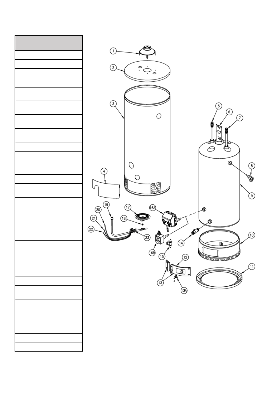
PARTS DIAGRAM
PART NAME AND
DESCRIPTION
1. Draft Diverter
2. Jacket Head Pan
3. Jacket
4. Outer Door
5. Magnesium Anode–
Hot Water Outlet
6. Flue Baffle
Assembly
7. Dip Tube–Cold
Water Inlet
8. Temperature and
Pressure Relief Valve
9. Glass Lined Tank
10. Combustion
Chamber Assembly
11. Jacket Base Pan
12. Inner Door Gasket
13. Inner Door
Assembly
13A. High temperature
limit switch
14. Drain Valve
15. Piezo Igniter – Use
with White Rogers Gas
Control
16A. Gas Control Valve
– Honeywell
16B. Gas Control Valve
– White Rogers
17. Steel Burner
18. Orifice
19. Gas Feedline to
Burner
20. Gas Feedline to
Pilot
21.
Thermocouple/Thermo
pile Lead
22. Piezo Igniter Lead
23. Pilot Assembly
31
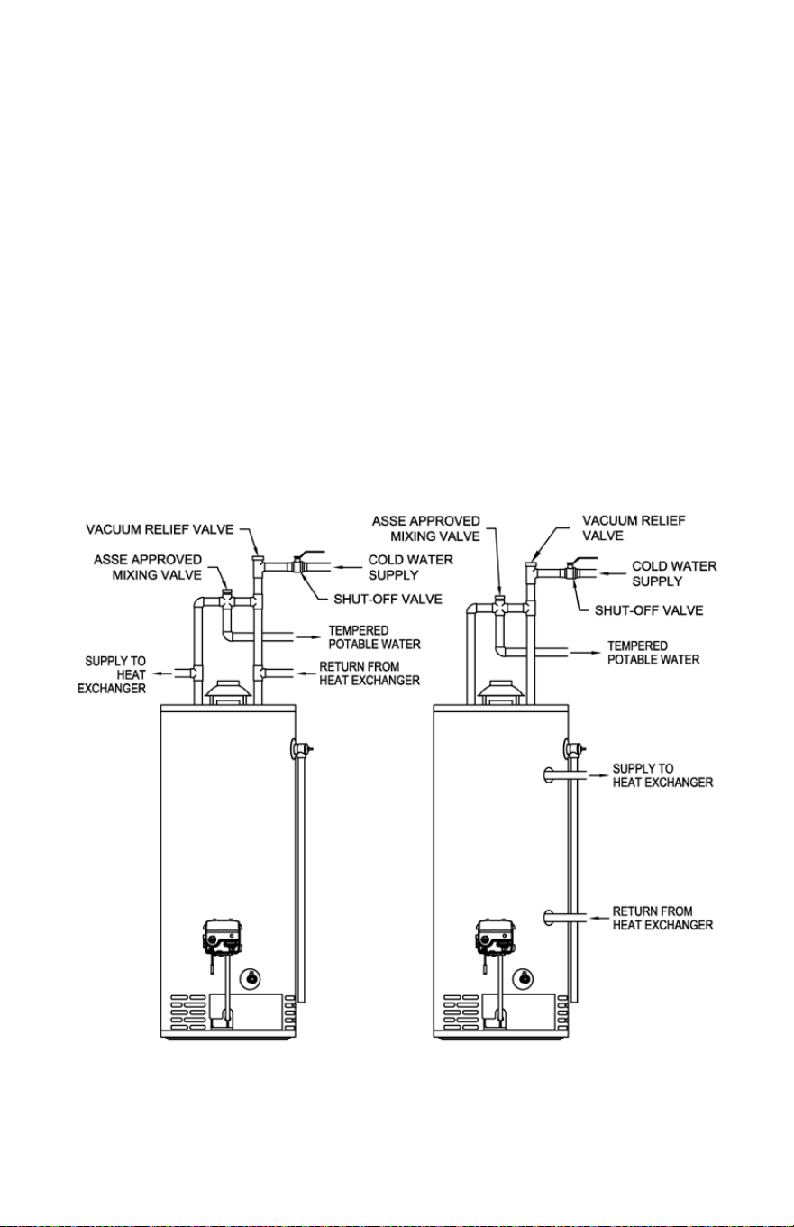
THE FOLLOWING INSTRUCTIONS ARE FOR INSTALLATION
OF: GAS WATER HEATERS SUITABLE FOR WATER
(POTABLE) HEATING AND SPACE HEATING
1. All piping components connected to this water heater for space heating
applications must be suitable for use with potable water. In
Massachusetts, space heating piping length must NOT exceed 50 ft.
2. Toxic chemicals, such as those used for boiler treatment, must NOT be
introduced into potable water used for space heating.
3. This water heater must NOT be connected to an existing heating system
or component(s) previously used with a non-potable water heating
appliance.
4. When the system requires water for space heating at temperatures higher
than required for other uses, an ASSE approved mixing valve shall be
installed to temper the water for those uses in order to reduce scald
hazard potential.
Please refer to Figure 12 and Figure 13 for suggested piping arrangements.
Figure 12 Figure 13

32
NOTES