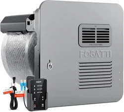
Installation and Operation Manual
Tank RV Water Heater
300517
CSA/ANSI Z21.10.1 • CSA 4.1-19
MODEL:
FSGE-HS6
FSGE-HS10
- Do not store or use gasoline or other flammable vapors and liquids in the vicinity of this or any other
appliance.
- Installation and service must be performed by a qualified installer, service agency or the gas supplier.
Ÿ Do not turn on the gas supply until the gas leak(s) has been repaired.
Ÿ Evacuate all persons from the vehicle.
Ÿ Do not start the vehicle's engine of electric generator.
Ÿ Shut off the gas supply at the gas container or source.
- WHAT TO DO IF YOU SMELL GAS
Ÿ If you can not reach a gas supplier or qualified service technician, contact the nearest fire department.
Ÿ Do not touch an electrical switch, or use any phone or radio in the vehicles.
Ÿ Contact the nearest gas supplier or qualified service technician for repairs.
Manuel d'installation et d'utilisation
Chauffe-eau De Réservoir VR
WARNING
If the information in these instructions is not followed exactly, a fire or
explosion may result causing property damage, personal injury or death.
Please read these instructions carefully and follow all instructions, guidelines, and warnings included in
this product manual in order to ensure that you install, use, and maintain the product properly at all
times. These instructions MUST stay with this product. By using the product, you hereby confirm that you
have read all instructions, guidelines, and warnings carefully and that you understand and agree to
abide by the terms and conditions as set forth herein. You agree to use this product only for the
intended purpose and application and in accordance with the instructions, guidelines, and warnings as
set forth in this product manual as well as in accordance with all applicable laws and regulations. A
failure to read and follow the instructions and warnings set forth herein may result in an injury to
yourself and others, damage to your product, or damage to other property in the vicinity. This product
manual, including the instructions, guidelines, and warnings, and related documentation, may be
subject to changes and updates.
- Do not store or use gasoline or other flammable vapors
and liquids in the vicinity of this or any other appliance.
Ÿ Shut off the gas supply at the gas container or source.
Ÿ Do not start the vehicle's engine of electric generator.
- WHAT TO DO IF YOU SMELL GAS
Ÿ Evacuate all persons from the vehicle.
Ÿ Contact the nearest gas supplier or qualified service
technician for repairs.
Ÿ Do not touch an electrical switch, or use any phone or radio
in the vehicles.
Ÿ If you can not reach a gas supplier or qualified service
technician, contact the nearest fire department.
- Installation and service must be performed by a qualified
installer, service agency or the gas supplier.
Ÿ Do not turn on the gas supply until the gas leak(s) has been
repaired.
WARNING
If the information in these instructions is not followed
exactly, a fire or explosion may result causing
property damage, personal injury or death.
EN

CONTENTS
EN
1.3 Supplemental Directives
4.9 Performing Leak Testing
7 Troubleshooting
7.2 Non-defect When the Following Conditions Occur
6.7 Using After-Market Water Heating Element Devices
1 Explanation of Symbols and Safety Instructions
3.1 Unit Specifications
4 Installation
5.5 High Altitude Use
4.4 Installing the Gas Pipe
4.2 Blocking the Water Heater
4.1 Preparing the Installation Location
4.5 Installing the Wired Controller
4.7 Wiring the 12 VDC Power Supply
6.1 Performing Preventative Maintenance
1.4 General Safety Messages
1.2 Understand Signal Words
3 General Information
4.3 Installing the Water Hose
4.6 Wiring the 120 VAC Power Supply
5.2 Wired controller operation
6.3 Maintaining the Water Heater Tank
3.2 Component Locations
5.3 Thermostat Manual Reset
2 Intended Use
5 Operation
5.4 Shutting Down the Water Heater
6 Maintenance and Care
6.2 Electronic Ignition Module Cleaning
3.3 Technical Parameters
6.4 Operation and Maintenance T & P Pressure Relief Valve
6.5 Draining and Storage Instructions
1.1 Recognize Safety Information
4.8 Installing the Unit
5.1 Operating instructions
6.6 Winterizing
7.1 Fault Description and Troubleshooting
8 Wiring Diagrams
9 Replacement Parts: Components
Warranty Policy
French
23
20
24
23
28
29
24
34
24
23
27
30
33
26
31
29
27
32
20
22
21
05
05
06
05
05
06
07
07
08
09
10
11
11
12
15
12
13
14
18
19
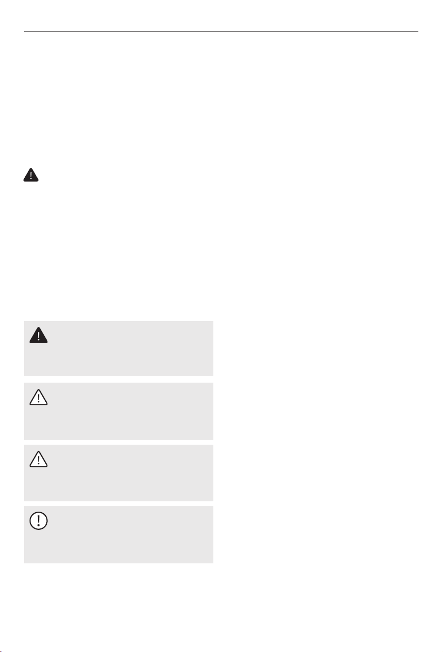
1 Explanation of Symbols
and Safety Instructions
1.1 Recognize Safety Information
This manual has safety information and
instructions to help you eliminate or reduce the
risk of accidents and injuries.
CAUTION
Indicates a hazardous situation which,
if not avoided, could result in property
damage and minor or moderate injury.
1.3 Supplemental Directives
WARNING
Indicates a hazardous situation that, if
not avoided, could result in death or
serious injury.
DANGER
Indicates an imminently hazardous
situation which, if not avoided, will
result in death or serious injury.
NOTICE
This symbol indicates important
information where there is no risk to
people or property.
To reduce the risk of accidents and injuries,
please observe the following directives before
proceeding to install or operate this appliance:
Ÿ Read and follow all safety information and
instructions.
Ÿ Read and understand these instructions
before installing, operating, or servicing this
product.
Ÿ The installation must comply with all
applicable local or national codes, including
the latest edition of the following standards:
Ÿ Installation and service must be performed
by a qualified Service Technician, Service
Center, OEM, or Gas Supplier.
– ANSI/NFPA70, National Electrical Code
(NEC)
– A119.5, Park Trailers
– ANSI Z21.10.1, Gas Water Heaters
– CAN/CGA B149 Installation Codes
– CSA Z240 RV Series, Recreational Vehicles
– ANSI Z223.1 National Fuel Gas Code
– Federal Mobile Home Construction & Safety
Standard, Title 24 CFR, part 3280, or when
this Standard Is not applicable, the
Standard for Manufactured Home
Installations (Manufactured Home Sites,
Communities and Set-Ups), ANSI A255.1
– CAN/CSA-Z240 MH Series, Mobile Homes
Canada
– ANSI/NFPA 1192, Recreational Vehicles
Code
U.S.A.
– CSA C22.1, Parts l & ll, Canadian Electrical
Code
– CSA 4.1 (latest edition)
Explanation of Symbols and Safety Instructions
This is the safety alert symbol. It is used to
alert you to potential physical injury
hazards. Obey all safety messages that
follow this symbol to avoid possible injury
or death.
1.2 Understand Signal Words
A signal word will identify safety messages
and property damage messages, and also will
indicate the degree or level of hazard
seriousness.
05
2 Intended Use
This Water Heater is designed and intended for
use in a recreational vehicle (hereinafter
referred to as "RV") for which it is supplied.
This product is designed to heat water and is
not intended to be used as a space heater for
hydronic heating. This Water Heater is only
suitable for the intended purpose and
application in accordance with these
instructions.
This manual provides information that is
necessary for proper installation, operation,
and maintenance of the Water Heater. Poor
installation and/or improper operating or
maintenance will result in unsatisfactory
performance and a possible failure. The
manufacturer accepts no liability for any injury
or damage to the product resulting from:
Ÿ Incorrect assembly or connection, including
excess voltage.
Ÿ Use for purposes other than those described
in this manual.
Ÿ Incorrect maintenance or use of spare parts
other than original spare parts provided by
the manufacturer.
Ÿ Alterations to the product without express
permission from the manufacturer.
Intended Use
Disposal
Place the packaging material in the
appropriate recycling waste bins,
whenever possible. Consult a local
recycling center or specialist dealer
for details about how to dispose of
the product in accordance with all
applicable national and local
regulations.
WARNING
This product can expose you to lead,
which is known to the state of
California to cause cancer and birth
defects or other reproductive harm. For
more information, go to
www.P65warnings.ca.gov.
1.4 General Safety Messages
WARNING
Ÿ Do not store or use gasoline or other
flammable vapors and liquids in the
vicinity of this or any other appliance.
Ÿ Follow the information in this manual
exactly.
Failure to obey the following warnings
could result in death or serious injury:
WARNING
Keep the water heater area clear of
combustible cleaning materials,
gasoline, and other flammable vapors
and liquids. Failure to obey this
warning could result in death or
serious injury.
FREEZE WARNING
Drain or fill with RV approved
antifreeze if subject to freezing
temperatures when storing for winter.
Fire and/or explosion hazard
Burn hazard, fire, explosion, and/or
carbon monoxide hazard.
06
General Information
3 General Information
NOTICE
The images used in this document are
for reference purposes only.
Components and component locations
may vary according to specific product
models. Measurements may vary
±0.38 in. (10 mm).
This section provides reference information
regarding the recommended installation tools
and materials, the unit components, and the
model identification associated with the
different water heater models.
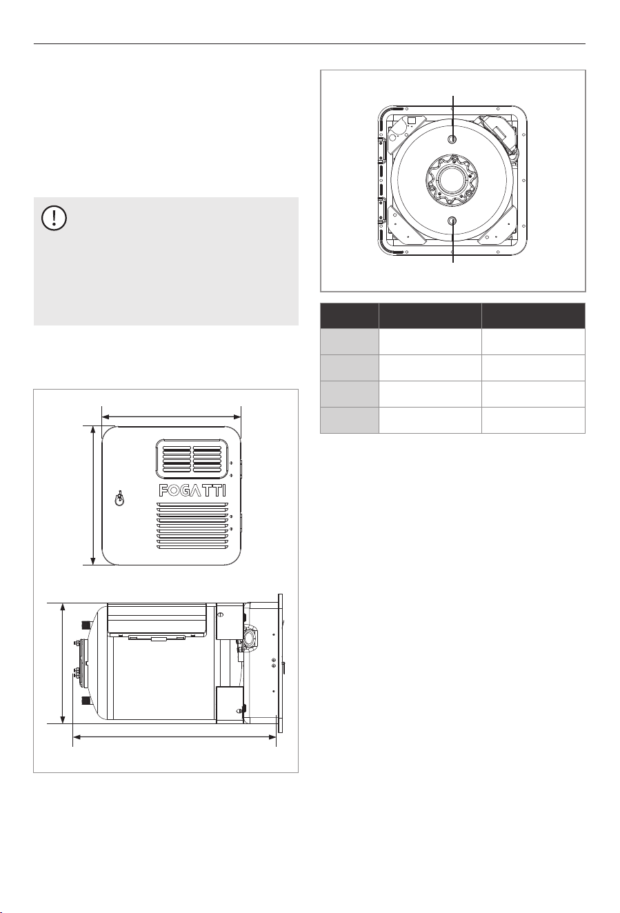
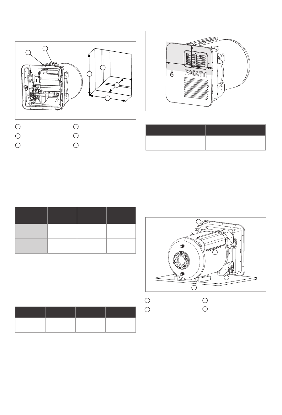
3.1 Unit Specifications
Water Outlet 1/2"NPT
Water inlet 1/2"NPT
A
B
C
D
Model
A
15.0" (380 mm)*
15.0" (380 mm)
21.4" (544 mm)
12.8" (324 mm)
B
FSGE-HS6
18.5" (470 mm)
18.5" (470 mm)
20.6" (523 mm)
16.3" (414 mm)
FSGE-HS10
C
D
* FSGE-HS6 adjustable door frame: 15" or 18" Width.
07
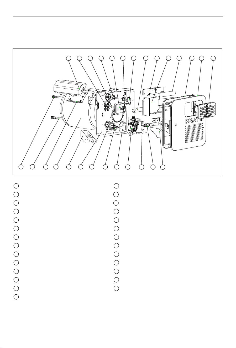
3.2 Component Locations
This section provides the component locations for each Water Heater model.
1
2
3
4
5
6
7
8
9
10
11
12
13
14
16
17
18
19
20
21
22
23
24
25
26
27
Water level pipe
Water diffuser
Controller bracket
Water storage tank
Metal bracket
Metal shell
Heating tube
Titanium rod
Heat pipe covers
Gas valve
Regulator valve support
Burner
Diversion hood
Smoke exhaust net
General Information
15
Panel assembly
Cabinet flange cover
Deflector plate
Top exhaust hood
Front exhaust hood
Deflector plate
Temperature and Pressure Relief Valve
Rubber grommet
Thermostat cover
TP safety valve joint
Temperature probe
Thermostat
Controller
1
2
3
4 5 6 7 8 9
10 11 12
13
14
151626 25 24 23 22 21
20
19 18 1727
08
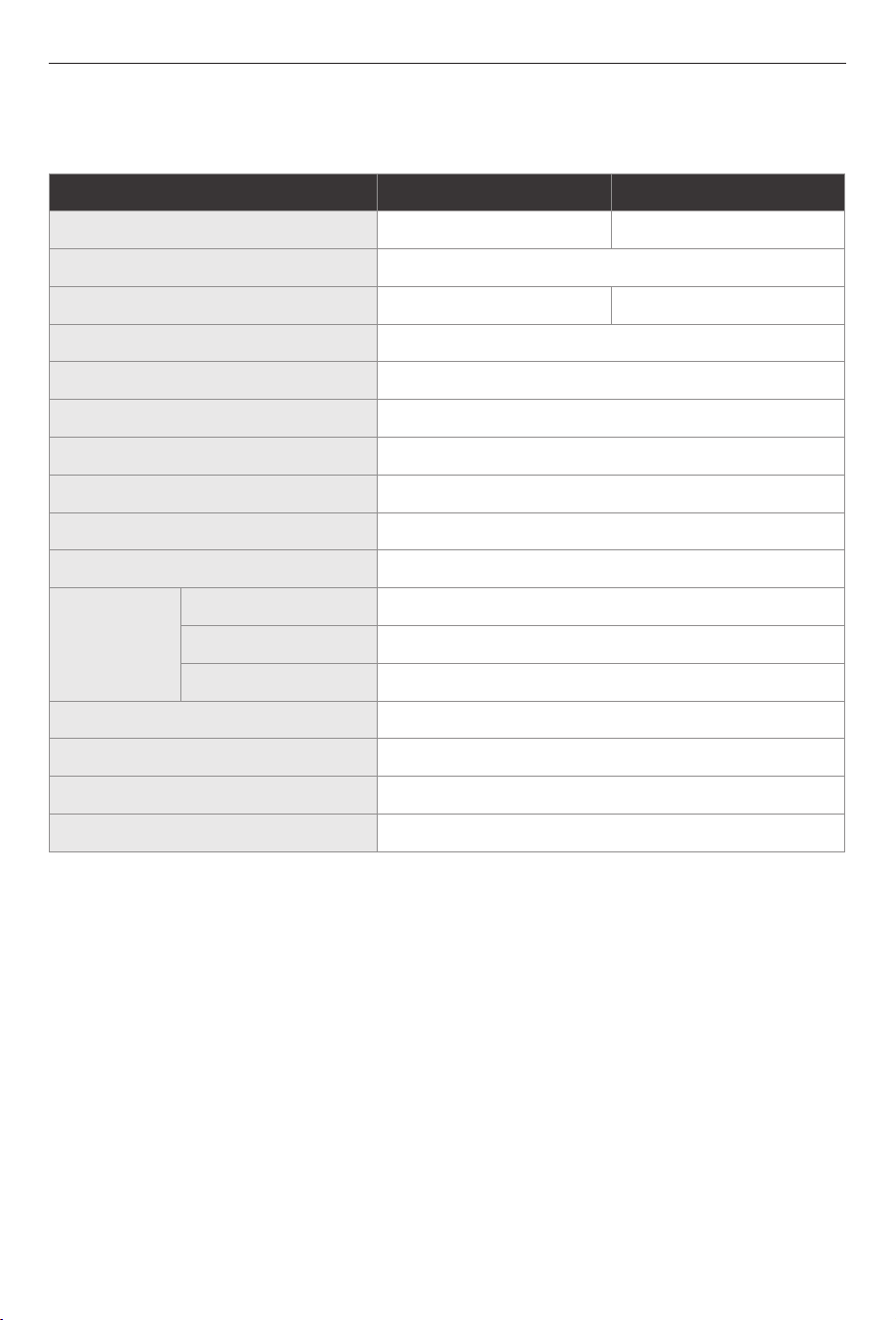
3.3 Technical Parameters
Model
Capacity (Gallons)
6 gallons
Range of adjustment
104 °F (40 °C); 122 °F (50 °C); 140 °F (60 °C);
FSGE-HS6 FSGE-HS10
10 gallons
12,000
Orifice Drill Size
40mil for LPG
12,000
Max. Heat Input (Btu/hr)
Max. Inlet Gas Pressure
13" wc(3.23 kpa)
8" wc(1.99 kpa)
Min. Inlet Gas Pressure
<16
Rated Gas Inlet Pressure
LPG 11" wc 2.74 kpa
Total Input Current (A)
Ignition method
Pulse continuous ignition
5/8" UNF
Gas inlet
1/2" NPT
Cold water inlet
1/2" NPT
Electric supply
AC 120 V / 60 Hz
Hot water outlet
Rated gas heating electric power (W)
7W ± 1W
Max. Temperature
140 °F (60 °C)
1440 W
Rated electric heating power (W)
Connector
Specification
Water Heater Specifications Table
General Information
Nominal Input Voltage
12V DC (ignition and gas heating)
09
4 Installation
DANGER
This product can produce carbon
monoxide, which has no odor and can
be life-threatening. Avoid improper
adjustment, alterations, service, or
maintenance. Follow instructions for
the proper installation of this
appliance. Failure to obey this danger
notification can result in improper
installation causing carbon monoxide
poisoning that will result in death or
serious injury.
: CARBON MONOXIDE
POISONING HAZARD.
WARNING
Failure to obey the following
warnings could result in death or
serious injury:
Ÿ Shut off the gas supply, disconnect
the 120 VAC power from RV, and
disconnect the positive (+) 12 VDC
terminal from supply battery before
drilling or cutting into the RV.
Ÿ Make sure there are no obstacles
(wires, pipes, etc.) inside of the RV
roof or walls at the installation
locations.
: FIRE AND/OR ELECTRICAL
SHOCK HAZARD.
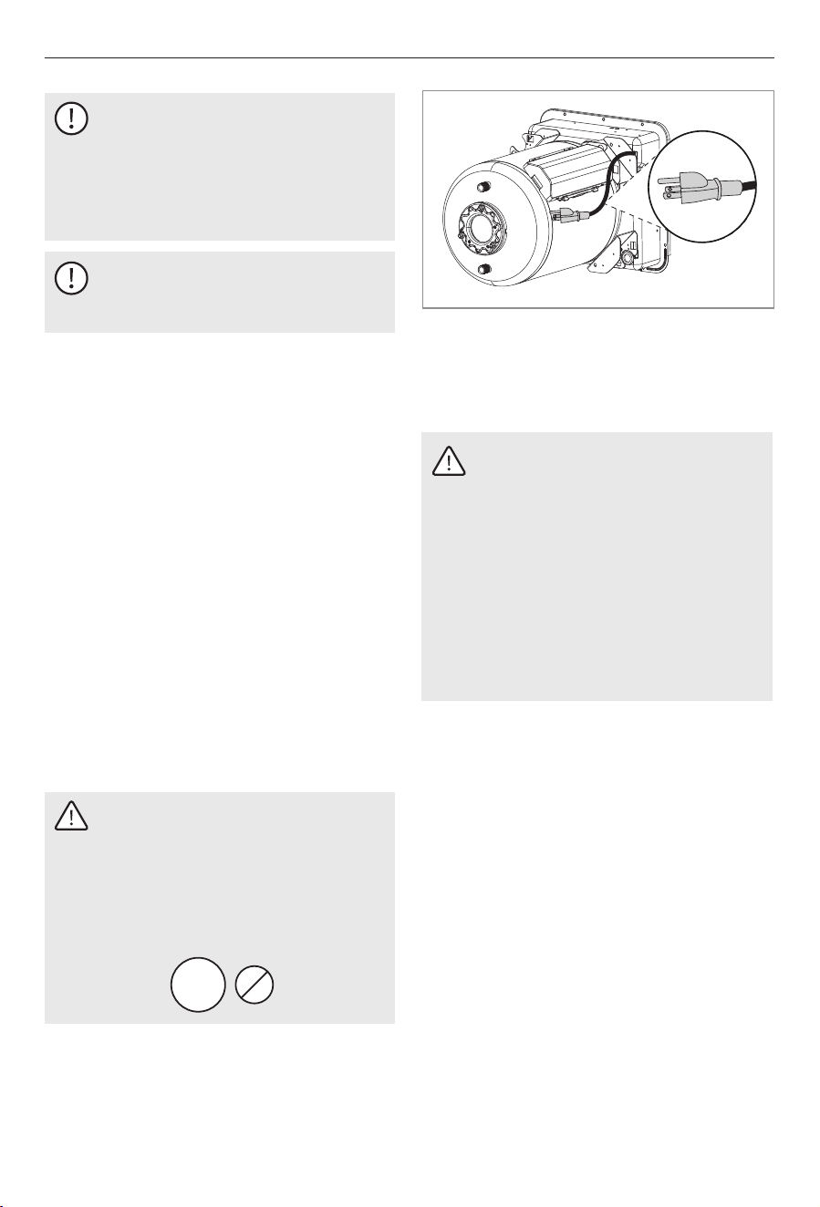
WARNING
This appliance is equipped with a
three-prong (grounding) plug for your
protection against shock hazards and
should be plugged directly into a
properly grounded three-prong
receptacle. Do not cut or remove the
grounding prong from this plug.
Failure to obey this warning could
result in death or serious injury.
: ELECTRICAL GROUNDING
INSTRUCTIONS.
Ÿ If the appliance is installed where a
connection or tank leakage can damage an
adjacent area, install a drain pan (which can
be drained outside of the RV) under the
Water Heater.
Ÿ To install the Water Heater on carpeting,
install the Water Heater onto a metal or
wood panel that extends at least 3 in. (7.62
cm) beyond the total width and depth of the
Water Heater.
Ÿ The water heater tank must be supported at
the same level as the bottom of the sidewall
cutout. Provide adequate clearance at the
rear of the unit for easy service access to the
water connections.
Ÿ This appliance must be installed by a
qualified professional installer.
This section describes how to install the Water
Heater and control switch. Please consider the
following directives prior to beginning
installation:
Installation
WARNING
The appliance should be located in an
area where leakage of the tank or
connections will not result in damage
to the area adjacent to the appliance
or to lower floors of the structure.
When such locations cannot be
avoided, it is recommended that a
suitable drain pan, adequately
drained, be installed under the
appliance. The pan must not restrict
combustion air flow.
10
The following figure and table show the
minimum required clearances between the
water heater vent and any projection or plastic
part on the side of the RV.
3 in
(76 mm)
12 in
(305 mm)
Sides
Top
4. Bend all flanges 90° along the scored lines.
5. Block the Water Heater.
3. Frame the cutout with 2 × 2 lumber or
equivalent.
4.2 Blocking the Water Heater
1
Water Heater
3
Floor
2
Cutout Frame
4
Wood Block
Installation
The cutout width and height tolerence is ± 1/8
in. (±3.0 mm) on all models.
The following table shows the requirements
for the minimum clearance from combustible
construction.
0 in
(0 mm)
0 in
(0 mm)
0 in
(0 mm)
Back
Top
Bottom
Sides
0 in
(0 mm)
4.1 Preparing the Installation Location
3
4
5
6
2. Erect the side walls and cut the square
opening. Refer to the following tables for
cutout and clearance specifications for basic
water heater models.
1. Plan the location of the Water Heater within
the RV.
1
Water Heater
4
Cutout Width
2
Flange
5
Cutout Height
3
Cutout Frame
6
Cutout Depth
1
2
Model
FSGE-HS6
13.0 in
(330 mm)
13.0 in
(330 mm)
21.4 in
(544 mm)
Cutout
Width
Cutout
Height
Cutout
Depth
FSGE-HS10
16.5 in
(419 mm)
16.5 in
(419 mm)
20.6 in
(523 mm)
3
4
1
2
11
Installation
2. At the back of the cutout, measure the
distance between the side of the cutout and
the side of the Water Heater.
5. Place a block of 2 x 2 lumber (minimum)
that is at least 6 in. (15 cm) long at each
marked location.
3. Remove the Water Heater from the cutout
location.
6. Secure the wood blocks to the floor.
4. Mark the appropriate measured distance
taken in step 2 on each side along the back
of the cutout.
1. Place the Water Heater into the cutout
location.
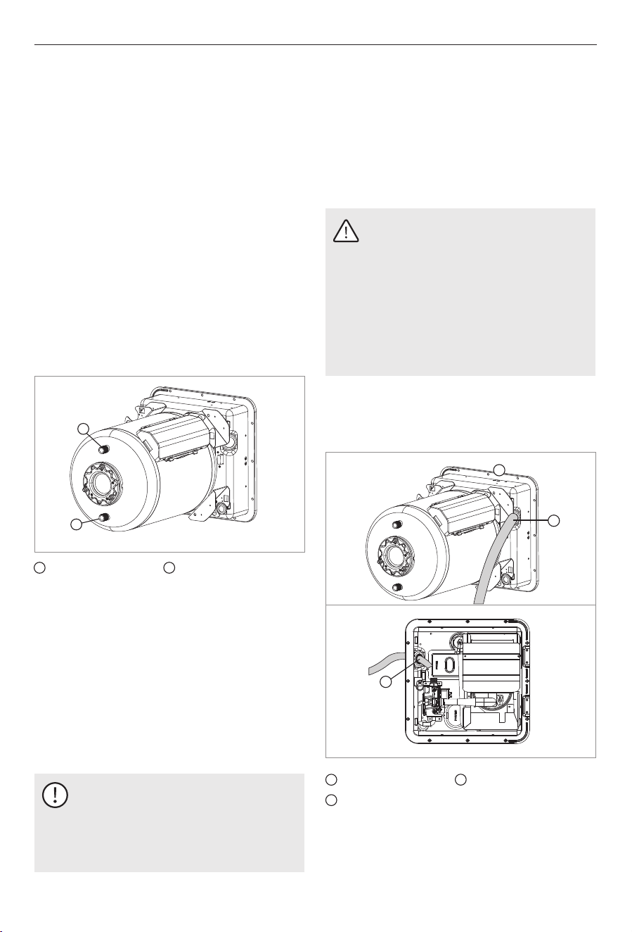
4.3 Installing the Water Hose
1
2
1
Cold Water Inlet
2
Hot Water Outlet
2. Remove the thread protector from the 1/2
in. (1.27 cm) hot water outlet.
3. Apply pipe sealant to the threads of the 1/2
in. (1.27 cm) National Pipe Tapered (NPT)
hot water outlet hose.
1. Position the Water Heater onto the planned
location on the floor of the RV.
4. Connect the 1/2 in. (1.27 cm) (NPT) hot
water outlet hose to the proper fitting on
the Water Heater using a suitable fitting.
NOTICE
Allow flexibility in the water and gas
hoses so you can pull the unit forward
through the wall 1 in (2.54 cm) past
the skin.
4.4 Installing The Gas Pipe
Rear
1
Water heater
3
Gas pipe
2
Over the line sheath
Front
5. Remove the thread protector from the 1/2
in. (1.27 cm) cold water inlet.
7. Connect the 1/2 in (1.27 cm) (NPT) cold
water inlet hose to the proper fitting on the
Water Heater using a suitable plastic fitting.
6. Apply sealant to the threads of the 1/2 in
(1.27 cm) (NPT) cold water inlet hose.
CAUTION
If a water heater is installed in a
closed water supply system, such as
one having a backflow preventer in
the cold water supply line, means
shall be provided to control thermal
expansion. Contact the water supplier
or local plumbing inspector on how to
control this situation.
2
1
3
12
4. Pull the 5/8 in. (15.87 mm) gas pipe and
grommet through the opening in the water
heater housing.
5. Connect the flare fitting and press the
grommet into the opening. Caulk around the
grommet if the grommet was cut during the
gas pipe installation.
6. Turn on gas and check all fittings and
connections for leaks, using a soap and
water solution. Correct even the slightest
leak immediately.
NOTICE
If the 5/8 in. (15.87 mm) gas pipe is
already flared, cut the grommet on
one side. Place the split grommet over
the gas pipe and press it into the
opening in the housing.
NOTICE
The 12 VDC control wiring in the Water
Heater is 18-gauge stranded wire
rated for 105 °C (221 °F). This 18-
gauge wire should be sufficient for
the 12 VDC control wire coming from
the Water Heater to the switch and
the 12 VDC power source; however,
consult all local and national codes
relating to your specific installation to
verify.
WARNING
Ÿ It is imperative that grommet and
gas pipe through grommet be
caulked air tight. If not tightly sealed,
moisture and potential harmful flue
products could vent through opening
and into living area of trailer.
Ÿ Do not use an open flame to check
for leaks!
4.5 Installing the Wired Controller
Recommends that the Water Heater unit be
connected directly to a 12 VDC battery or to the
filtered side of an AC/DC converter. Avoid
connections to the unfiltered side of an AC/DC
converter whenever possible. Use a minimum
of 18-gauge wire, UL and CSA listed.
Installation
1. Connect the 5/8 in. (15.87 mm) flared L.P.
gas pipe to the Water Heater.
2. Slide the grommet onto the 5/8 in. (15.87
mm) tubing.
3. Flare the gas pipe as necessary.
4.5.1 Preparing the Wired Controller
Installation Location
WARNING: FIRE AND/OR ELECTRICAL
SHOCK HAZARD.
Failure to obey the following
warnings could result in death or
serious injury:
Ÿ Make sure there are no obstacles
(wires, pipes, etc.) inside of the RV
roof or walls at the installation
locations.
Ÿ Shut off the gas supply, disconnect
the 120 VAC power from RV, and
disconnect the positive (+) 12 VDC
terminal from supply battery before
drilling or cutting into the RV.
When planning the location of the control
switch(es), be sure to choose an easily
accessible area for both use and service.
13
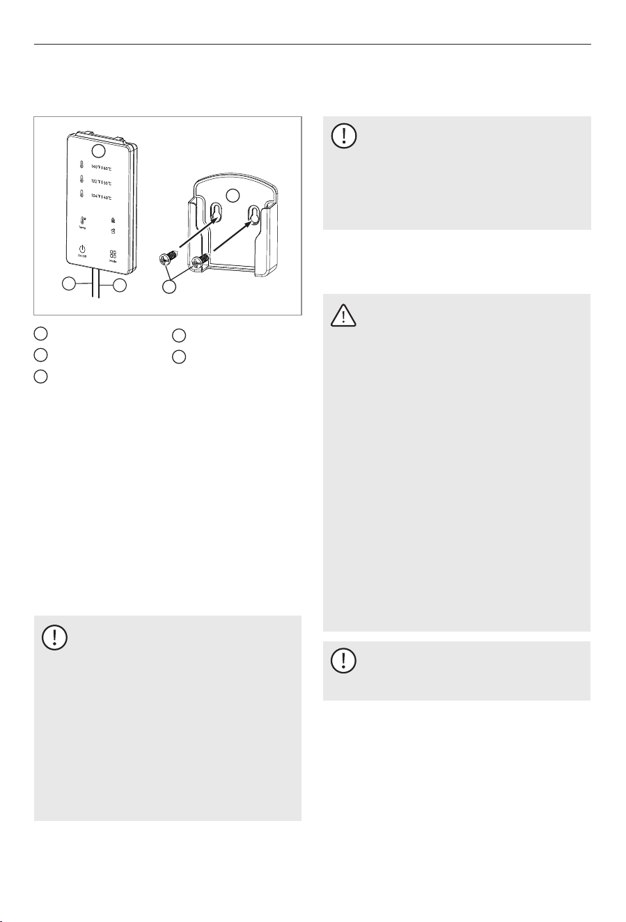
4.5.2 Completing the Wired Controller
Installation
1. Mount the controller base in a suitable
location using two ST4×16mm screws.
2. After mounting the base, complete the
wiring of the controller.
Ÿ Red Wire: Connect the controller’s red wire
to the appliance’s blue wire (Signal Wire –
for communication only).
Ÿ White Wire: Connect the controller’s white
wire to the appliance’s black wire (GND),
which should also be connected to the
negative terminal of the 12V DC power
supply.
4.6 Wiring the 120 VAC Power Supply
WARNING: FIRE HAZARD.
When a cord and plug connection to
the power supply are used on a water
heater, the power cord must be UL
listed as suitable for damp locations,
hard or extra hard usage. The cord
must be a flexible type such as S, SO,
ST, STO, SJ, SJT, SJTO, HS or HSO
described in the National Electric Code
ANSI/NFPA 70. The length of the
external cord to the water heater,
measured to the face of the
attachment plug, shall be no less than
2 ft (60.96 cm) and no more than 6 ft
(182.88 cm). The supply cord must be
a minimum of 14 AWG. The
attachment plug must be rated at 15
A. Failure to obey this warning could
result in death or serious injury.
NOTICE
Do not route wires around sharp
objects or where it could be smashed.
2
4
Wired controller
base
5
2-ST4X16
1
Red wire
White wire
3
Wired controller
Installation
NOTICE
Ÿ Only the original wired controller
provided by this company must be
used. Use of third-party or non-
original controllers may cause
malfunction or create safety hazards.
1
2
5
3
4
NOTICE
Ÿ For new installations, use the
provided 2-core shielded cable with
plug-and-play connection, and route
the cable to the appliance.
Ÿ For replacement of an old unit, you
may reuse the existing wiring by
connecting it through terminals.
Also, use the included red power
adapter cable to supply +12V power
to the appliance.
Ÿ For detailed wiring instructions, refer to
section 4.7 of this manual.
14
NOTICE
When using Romex® with a bare earth
ground, be sure to position the ground
wire so it does not contact the heating
element terminals. Damage to the
ground wire can occur.
NOTICE
Refer to "Wiring Diagrams" for a
comprehensive wiring schematic.
Ÿ Wires must have a capacity of 1400 W or
greater.
Ÿ The wiring method must conform to
applicable sections of article 551 of National
Electrical Code
Ÿ Use electrical metallic tubing, flexible metal
conduit, metal clad cable, or nonmetallic-
sheathed cable with a grounding conductor.
Ÿ All wiring must comply with applicable
electrical codes.
Ÿ The receptacle must be located per all
applicable codes and away from any water.
Consider the following before wiring the
control switch:
Ÿ ANSI/NFPA 70.
Ÿ The three-prong plug must be secured to a
UL approved, dedicated, minimum 15 A-
rated, three prong receptacle.
Installation
WARNING
The 120V AC power supply must be
connected. If the power supply is not
connected correctly, the water heater
will not start and the controller will be
damaged, which may result in serious
injury or death.
AC
240V
120V AC
Only
WARNING: ELECTRICAL SHOCK
HAZARD
Disconnect all power before
performing any work. Always use a
certified and properly grounded 12V
power supply that is isolated from the
RV. Follow all applicable codes,
regulations, and instruction materials
when performing service work. Failure
to follow instructions could result in
serious injury or death.
4.7 Wiring the 12 VDC Power Supply
(Updated for Three-Wire System)
Ÿ This appliance requires a 12 V DC power
source that provides a stable voltage
between 10 V and 17 V to operate correctly.
Ÿ Wiring connected to or in proximity to the
appliance must be rated for a minimum
temperature of 140 °F (60 °C). Use only
insulated terminals for all electrical
connections.
15
Installation
WARNING
The 12V DC power supply must be
connected correctly. Incorrect wiring
(especially reversed polarity or missing
connections) will prevent the heater
from starting and may damage the
controller, resulting in serious injury or
death.
DC
24V
DC
36V
DC
48V
Only
12V DC
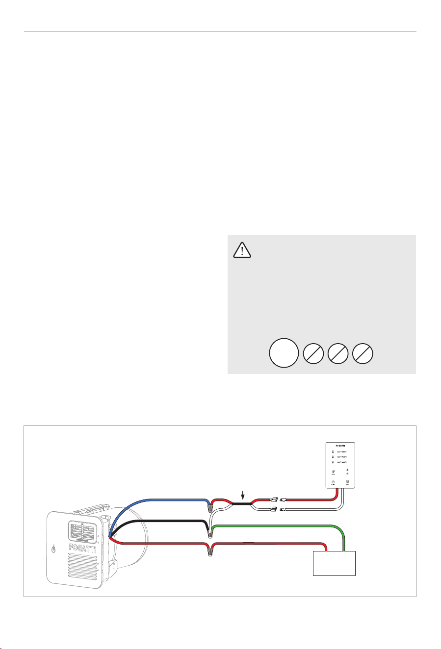
The wiring system has been upgraded to a
three-wire design to simplify installation and
improve reliability:
Updated Wiring Configuration:
Ÿ Blue: Signal Wire (used exclusively for
controller communication)
Ÿ Red: +12V Power Supply (direct connection to
the power supply positive terminal)
Ÿ Black: GND (shared ground for both the
appliance and the controller; connect to the
power supply negative terminal and the
controller’s white wire)
This replaces the previous 4-wire
configuration, which used separate GND lines
and signal/power separation between the
appliance and the controller.
Wiring Preparation Tips:
1. Select a distribution branch rated greater
than 3A (preferably 15A) to provide 12V to
the appliance from the RV’s distribution
panel.
NOTE: The appliance features a built-in 10A
fuse, accessible for service from the front. It
may be installed on a dedicated or shared
circuit.
2. (Optional) You may add a 12V switch in the
RV’s living area for convenience, although
the unit already includes an external power
switch.
If added, ensure any inline fuse or switch is
rated for at least 3A.
3. Locate the wiring entry point at the rear of
the appliance. Ensure the entry is not within
the appliance footprint and all edges are
protected to prevent abrasion.
4. Determine the appropriate wire gauge
(AWG) based on the wire length:
• 14 AWG: up to 66 feet (20 meters)
• 16 AWG: up to 40 feet (12 meters)
5. Feed the wires from the power source to the
entry point and make all secure connections
using insulated connectors, as shown in the
wiring diagram.
16
+
Red: +12VRed: +12V
Black: GND
Blue: Signal
Red: Signal
Green: GND
White: GND
-
Battery
Wired remote
control extension
cable
Installation
Replacing an Existing RV Water Heater
WARNING
Before beginning any work, disconnect
all power sources to the RV. Improper
handling of electrical wiring can result
in serious injury or death. Always
follow applicable safety codes and use
insulated tools and connectors.
In addition to standard installation, this
appliance supports fast replacement of older
RV water heaters. This method enables you to
reuse existing wiring, thereby minimizing the
time required for rewiring.
Quick Replacement Steps:
+12V
GND
Signal
1. Remove the original RV water heater.
Ÿ Red: +12V DC Power (positive)
Identify and clearly label the three original
connection wires that will be reused. These
are typically color-coded as follows:
Ÿ Green: GND (negative / chassis ground)
Ÿ Blue: Signal Wire (controller
communication line)
Ÿ Red (x2): One for +12V IN (from RV power),
one for +12V OUT (to the appliance).
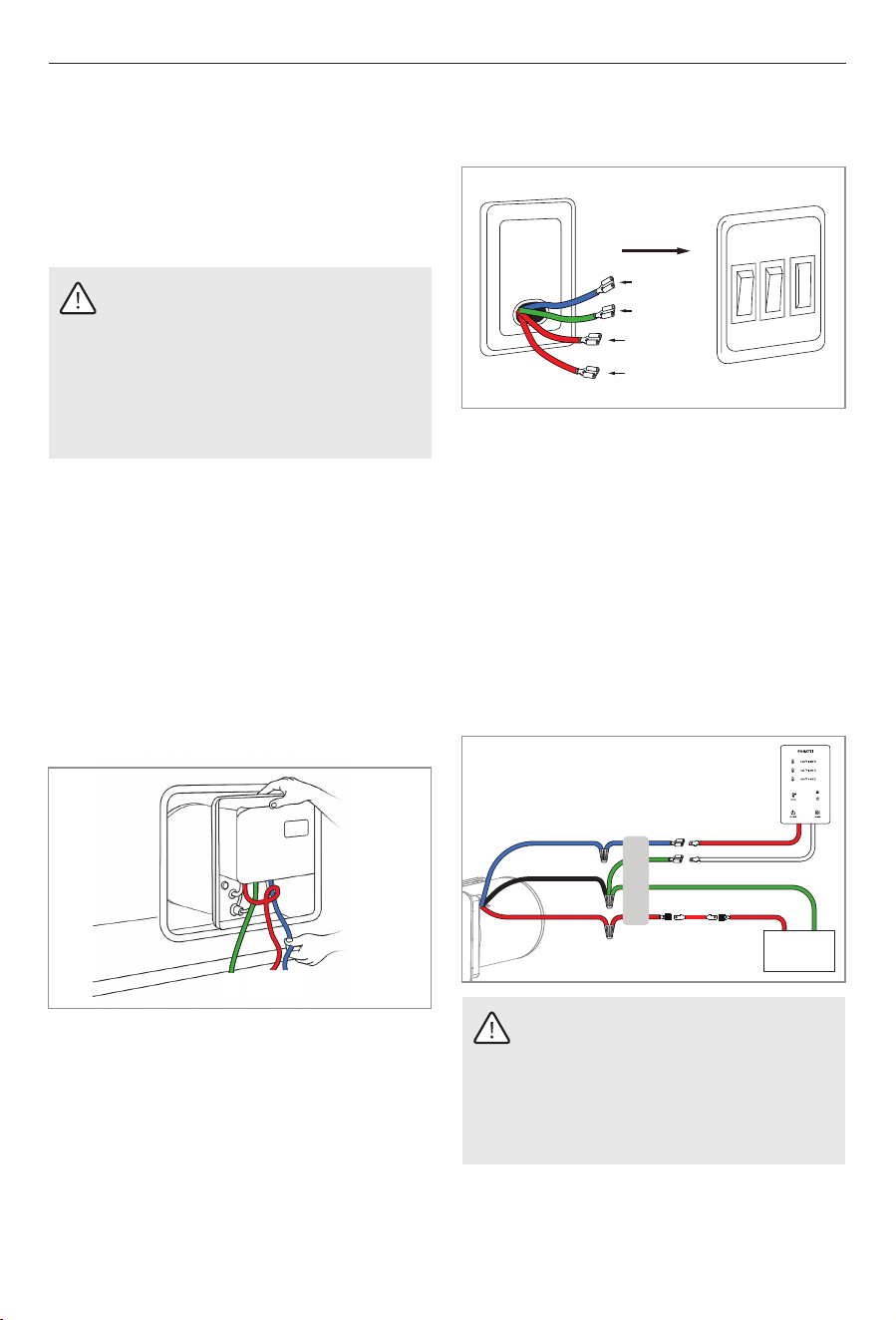
2. Remove the old wired controller.
Unplug the existing controller connector and
label the four exposed wires. These typically
include:
Ÿ Blue: Signal wire (same as the original
blue wire connected to the appliance)
Ÿ Green: GND wire (same as the original
GND connected to the appliance)
+12V In
+12V Out
GND
Signal
3. Reconnect wires to the new appliance and
controller:
Ÿ Connect the blue signal wire from the
appliance to the red wire on the new
controller (signal wire input).
Ÿ Connect the GND wire (green) from the
appliance to the white wire on the new
controller (GND/Negative).
Ÿ Use the included T-tap or quick-connect
terminals to join the +12V IN and +12V OUT
wires together (red to red).
+
+12V out
Red: +12V
Black: GND
Blue: Signal
Red: Signal
Green: GND
White: GND
the existing wires
rough-in
Battery
-
WARNING
Ensure correct polarity and continuity
before powering the unit. Reversed or
incorrect wiring may prevent the
system from functioning or cause
damage to the controller.
Green: GND
+12V in
17
Blue: Signal
W
ATER HEATER
ON
R
ES
E
T
ON
CAUTION
Ÿ Do not lift, push, or misalign the
main burner tube. Damage to the
burner and the water heater can
occur.
Ÿ Do not modify the water heater in
any way.
NOTICE
Install in recreation vehicles only. RVs
are recreation vehicles designed for
temporary living quarters for
recreation, camping, or travel using
their own power or towed by another
vehicle.
4.8 Installing the Unit
WARNING: CARBON MONOXIDE, FIRE
AND/OR EXPLOSION HAZARD.
Ÿ Be sure the unit is vented and sealed
properly to avoid the collection of
carbon monoxide inside of the RV.
Ÿ All combustion air must be supplied
from outside of the RV. All
combustion products must be vented
to the outside of the RV.
Failure to obey the following
warnings could result in death or
serious injury:
Ÿ Do not vent the water heater with a
venting system that serves another
appliance.
Ÿ Do not high-potential test (HI-POT)
the water heater unless the DSI
control board has been disconnected
(DC HI-POT).
Ÿ Install the water heater on an
exterior wall with access to a door
opening to the outdoors.
Ÿ Do not alter the water heater for a
positive grounding system.
Ÿ Do not use a battery charger to
supply power to the water heater at
any time or when testing.
Ÿ Do not vent the water heater to an
outside enclosed porch area.
Ÿ Protect building material from flue
gas exhaust.
Installation
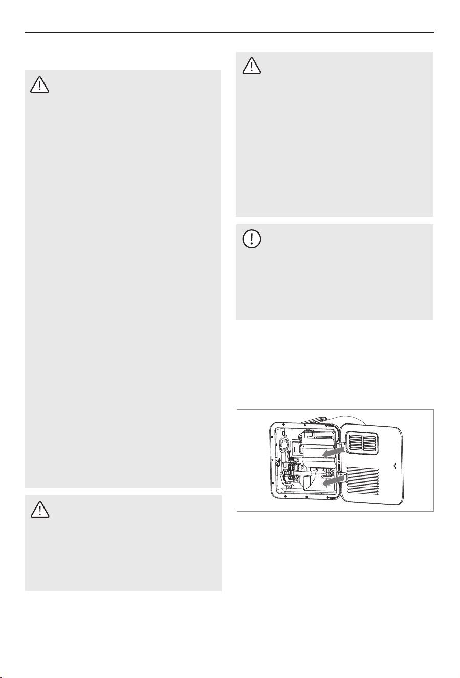
2. Remove the access door from the box,
separate the components.
1. The door of the rv water heater is fixed to
the mounting flange by a latch. You need to
rotate the door lock to open the door.
3. Caulk thoroughly around the opening and
the flange slots.
WARNING: Vertical Installation Only
Ÿ Do not install the unit on its side
under any circumstances.
Ÿ Improper orientation may cause
internal overheating, which could
result in malfunction, equipment
damage, or a serious fire hazard.
Ÿ This appliance must be installed in
an upright (vertical) position only.
Ÿ Always follow the specified
installation orientation to ensure
safe and reliable operation.
18
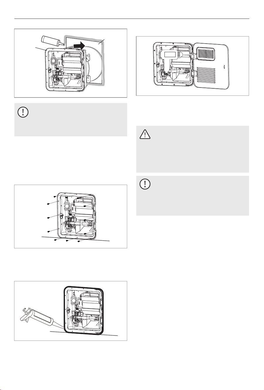
4. Press this product into the opened hole.
Secure the water heater to the car body with
12 screws (ST5×25 mm) Air and water
should be isolated from the openings to
prevent entry into the interior of the RV.
ST5×25 mm
5. Apply a liberal amount of sealant around
the door frame to fill any gaps to the RV wall
wipe any excess sealant.
Installation
4.9 Performing Leak Testing
NOTICE
Isolate the Water Heater from the gas
supply piping system before
performing any pressure test equal to
or greater than 0.5 PSI (34.5 mbar).
WARNING: FIRE AND/OR ELECTRICAL
SHOCK HAZARD.
Do not use matches, candles, or other
sources of control when checking for
gas leaks. Failure to obey this warning
could result in death or serious injury.
3. Check the tank and all water hose
connections for leaks.
1. Turn on the gas and check the Water Heater
and all of the connections for gas leaks
using leak detection solution.
2. Fill the water heater tank with water.
6. Install the water heater door.
NOTICE
Butyl tape 1-1/4 in. × 1/8 in. (32 mm ×
3 mm) may be substituted for caulking
material.
Opening
Flange
Slots
19
Operation
5 Operation
WARNING: Burn hazard, fire,
explosion, and/or carbon monoxide
hazard.
Keep the water heater area clear of
combustion cleaning materials,
gasoline, and other flammable vapors
and liquids. Failure to obey this
warning could result in death or
serious injury.
CAUTION: Explosion hazard.
If water heater has not been used for
more than two weeks, hydrogen gas
may form in the water line. Under
these conditions, to reduce the risk of
injury, open the hot water faucet for
several minutes at the kitchen sink
before you use any electrical
appliance connected to hot water
system. If hydrogen gas is present,
you will probably hear sounds like air
escaping through the pipe as water
begins to flow. Failure to obey this
warning could result in death or
serious injury.
WARNING: CARBON MONOXIDE, FIRE
AND/OR EXPLOSION HAZARD.
Ÿ Do not store or use gasoline or other
flammable vapors and liquids in the
vicinity of this or any other appliance.
Ÿ Should overheating occur, or the gas
supply fail to shut off, turn the operating
switch to the OFF position and close the
gas valve to stop the gas supply.
Ÿ Use with L.P. gas only.
Ÿ Shut off gas appliances and pilot lights
when refueling.
Failure to obey the following warnings
could result in death or serious injury:
Ÿ Turn gas off at the L.P. tank when the
vehicle is in motion. This disables all gas
appliances and pilot lights.
Ÿ Gas appliances must never be operated
while the vehicle is in motion.
Unpredictable wind currents may be
created which could cause flame reversal
in the burner tub, which could result in fire
damage. The thermal cut off fuse could
also be unnecessarily activated resulting
in a complete shutdown of the water
heater requiring replacement of the
thermal cutoff.
CAUTION: FIRE HAZARD.
Do not smoke or have any flame near
an open faucet. Failure to obey this
caution could result in minor or
moderate injury.
5.1 Operating instructions
Ÿ Users should confirm whether the water
heater is installed correctly before the first
use, and carefully check whether the
connection is correct without leakage.
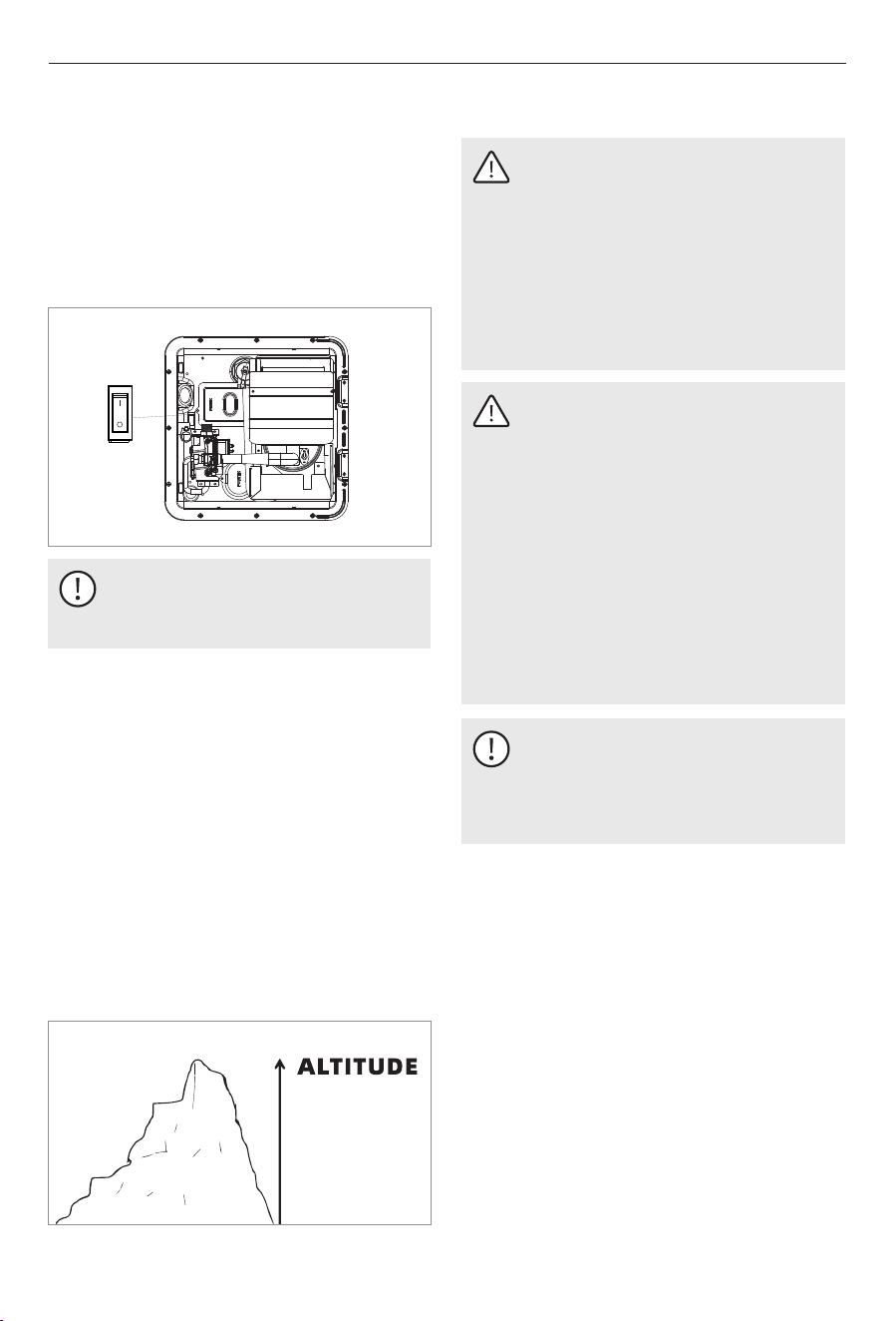
Ÿ Confirm that the power switch to the water
heater is turned on, turn the latch to close
the door.
ON
OFF
Ÿ Before showering or bathing, test the water
temperature with your hands to avoid burns.
Ÿ During and after the operation of the water
heater, the temperature at the exhaust outlet
and the surrounding part is high. Please do
not touch either with your hands to avoid
burns.
20
NOTICE
It is imperative that the water heater
tank be filled with water before
operating the water heater. Operation
of the water heater without water in
the tank may result in damage to the
tank and /or controls. This type of
damage is not covered by the limited
warranty.
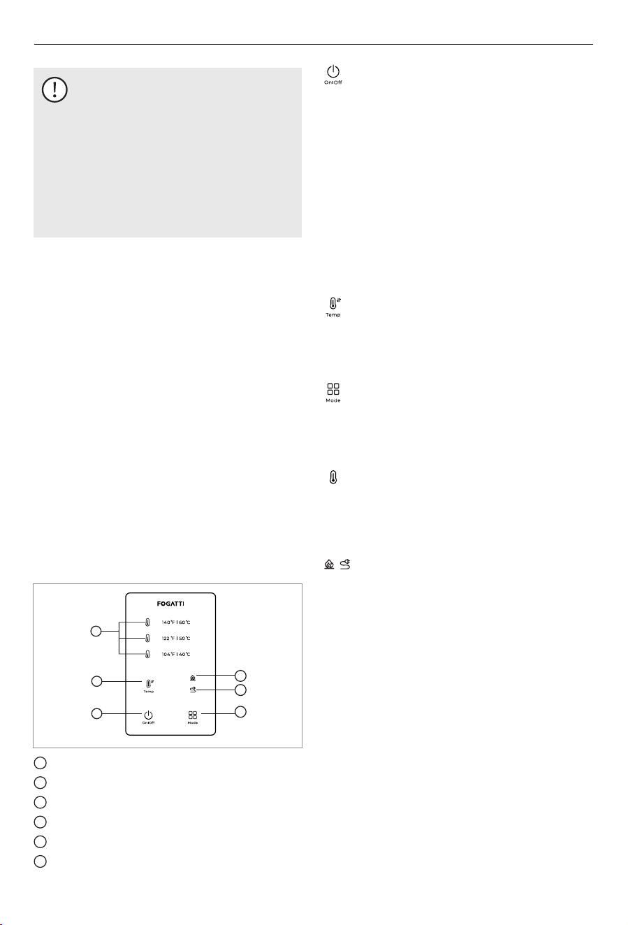
5.2 Wired controller operation
Gas heating display
Electric heating display
Heating mode button
Temperature display
ON/OFF button
1
2
3
4
5
6
1
2
3
4
5
6
3. In the case of a system failure, pressing this
button clears the fault code.
4. Fault indication: When a failure occurs, the
"On/Off button indicator" flashes a matching
number of times to show the various
problems.
ON/OFF button:
2. On/Off Indicator: When the power is turned
on, the indicator will be permanently on.
When the power is off, the indicator will be
shut off.
1. switch between on and off status.
At each press, the preset temperature of 104
°F (40 °C), 122 °F (50 °C) and 140 °F (60 °C)
can be selected and switched in cycles.
Temperature adjustment button:
Operation
Ÿ Wired controller to adjust desired
temperature.
Ÿ Procedures for adjusting the thermostat for
energy efficient operation at the minimum
water temperature setting consistent with the
consumer’s needs.
Ÿ The thermostat is adjusted to its lowest
temperature position when shipped from the
factory.
Ÿ There is a hot water scald potential if the
thermostat is set too high.
Ÿ Valves for reducing point of use temperature
by mixing cold and hot water are available.
Consult a licensed plumber or the local
plumbing authority.
Temperature adjustment button
Heating mode button:
At each press, select gas heating mode, electric
heating mode, gas and electric simultaneous
heating mode cycle switching.
Temperature indicator:
The temperature display lights up in red when
heating. The temperature display lights up in
green when heated to the preset temperature.
For one second, all lights are turned on. The
mode of the most recent power outage is also
displayed, as are the lights for the selected
temperature.
Power supply display:
Heating mode display:
When gas heating is selected, the gas heating
indicator will be on. When electric heating is
selected, the electric heating indicator will be
on. When the gas and electric heating mode is
selected, the gas and electric heating indicator
will be on.
21
5.2.1 Gas Heating Mode
WARNING: Burn hazard, fire,
explosion, and/or carbon monoxide.
Keep the water heater area away from
combustible cleaning materials,
gasoline, and other flammable vapors
and liquids. Failure to comply with this
warning may result in death or serious
injury.
When the power switch turns to the ON
position, click the switch button, select the
temperature that needs to be heated, and then
select the gas heating mode, the gas heating
indicator lights up, and the water heater starts
to try to ignite. If for some reason there is no
ignition, the switch indicator on the remote
controller flashes twice and beeps an alarm.
5.2.2 Electric Heating Mode
When the power switch turns to the ON
position, click the switch button, select the
temperature that needs to be heated, and
select the electric heating mode, the electric
heating indicator lights up, and the relay
closes and passes 120 VAC to the heating tube.
If the water heater fails, the switch indicator on
the wire controller flashes twice and beeps an
alarm.
5.2.3 Gas and Electric Simultaneous
Heating Mode
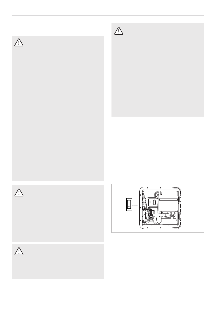
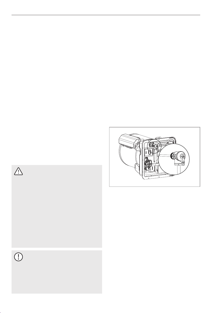
5.3 Thermostat Manual Reset
If the Water Heater fails to operate due to
high-water temperature, a lockout condition
will occur. Investigate the cause of overheating
and correct the issue before resetting the
Water Heater.
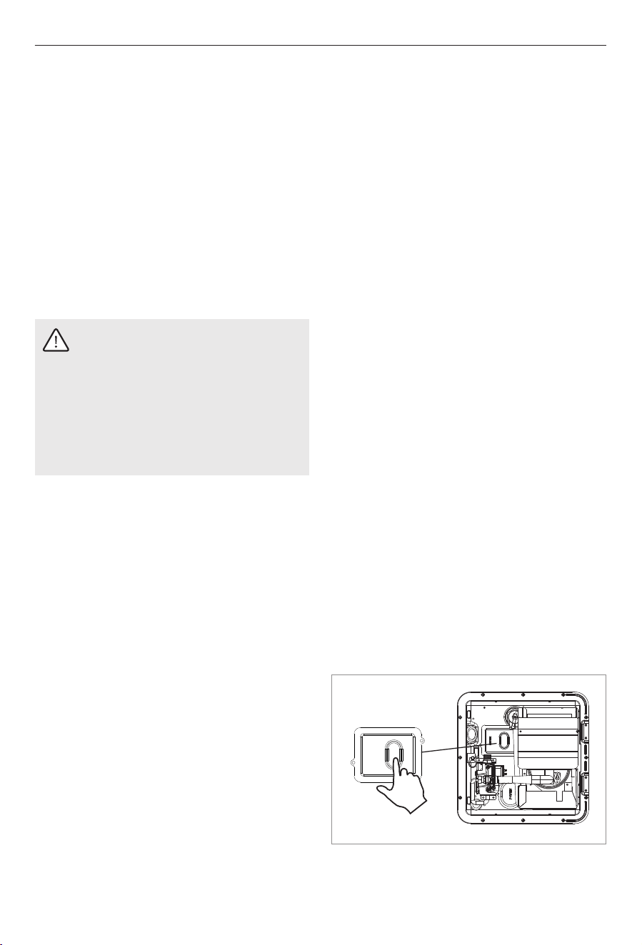
4. Open the door panel and press the button
as shown below to reset the thermostat.
3. Turn the control switch to the ON position.
1. Allow water to cool.
Investigate the cause of the overheating then
perform the following to reset the Water
Heater:
2. Place the control switch in the OFF position
and wait 30 seconds.
When the power switch turns to the ON
position, click the switch button, select the
temperature that needs to be heated, and then
select the gas-electric heating mode, the gas
and electric heating indicator lights up. If the
gas fails to ignite, the gas mode will lock, the
switch indicator flashes 3 times, and beeps the
alarm because the electric heating mode is still
running; If the electric heating mode is locked
and the gas heating mode is operating
normally, the switch indicator will flash 4 times
and beep the alarm.
Operation
3. When the heater reaches the preset
temperature, the buzzer will sound once and
enter into heat preservation state.
Buzzer:
1. When the heater is powered on or a proper
key operation is made, the buzzer makes a
"B" sound.
2. After a fault, the buzzer will sound
continuously for 30 seconds and may be
deactivated by hitting any key.
22
NOTICE
Perform these steps before performing
any service on the Water Heater.
1. Place the control switch in the OFF position.
2. Turn the power switch to the OFF position.
6 Maintenance and Care
WARNING: Carbon monoxide
poisoning hazard.
Gas flames consume oxygen, which
must be replaced to assure proper
combustion. Provide fresh air during
testing, service, and maintenance of
this appliance. Failure to obey this
warning can result in death or serious
injury.
WARNING: Fire or explosion hazard.
Failure to obey the following
warnings could result in death or
serious injury:
Ÿ When performing any maintenance
or care, shut off the gas supply at
the L.P. container before
disconnecting a gas line.
Ÿ Keep the control compartment clean
and free of gasoline, combustible
material and any flammable liquids
and vapors.
NOTICE
Ÿ During service of the controls, label all
wires before disconnecting any wires.
Ÿ Verify proper operation after servicing.
Have the gas pressure tested periodically. The
pressure should be set at 11 in. (27.94 cm) of
water column with three appliances running.
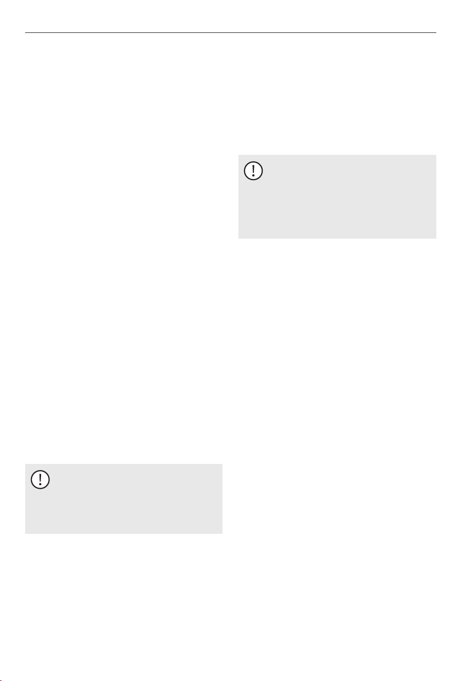
For US: 0~5000 ft above sea level.
For Canada: 0~4500 ft above sea level;
If it exceeds 5000 ft, it shall comply with the
requirements of Canadian installation
regulations CSA B149.1 and American
installation regulations ANSI Z223.1/NFPA54,
and the input rate will decrease by 4% for
every 1000 ft increase in altitude.
5.5 High Altitude Use
Periodically check the main burner flame.
Drain the Water Heater at regular intervals (at
least one time during the year).
Drain the Water Heater before storing the RV
for the winter or when the possibility of
freezing exists.
Keep the vent and combustion air grill clear of
any obstructions.
Have the gas pressure tested periodically. The
pressure should be set at 11 in. (27.94 cm) of
water column with three appliances running.
5.4 Shutting Down the Water Heater
ON
OFF
Maintenance and Care
If the lockout condition persists:
1. Read the Maintenance and Care Instructions
and the Electronic Control Maintenance in
this manual.
2. Contact a Service Center.
23
6.3 Maintaining the Water Heater
Tank
CAUTION: Scalding hazard.
Turn off the water heater and allow
time for the water to cool before
removing the drain plug to flush the
water heater tank. Failure to obey this
caution could result in minor or
moderate injury.
6.3.1 Winterizing the Unit
NOTICE
Ÿ Drain and flush the tank before long
term storage or freezing weather.
Ÿ To ensure the best performance of
the Water Heater and to extend the
life of the tank, periodically drain and
flush the water heater tank.
1. Turn off the main water supply (the pump,
the water supply, or the water hook up
source) then lift the handle on the T & P relief
valve. This will allow water to flow out of the
drain opening.
2. Clean and adjust the main burner.
4. Inspect the electrode for cracked porcelain.
3. Ensure the main burner and the valve
manifold are aligned with each other.
6. Check for intermittent functionality of the DSI
control board. If the DSI control board is
experiencing intermittent functionality,
remove the DSI control board and clean the
terminal block with a pencil eraser.
1. Inspect the main burner orifice.
5. Ensure the electrode gap between the
electrode and the ground is 0.125 in. (0.3175
cm).
6.2 Electronic Ignition Module
Cleaning
Maintenance and Care
6.1 Performing Preventative
Maintenance
Inspect and clean the burner tube on a regular
basis. Run a flexible wire brush down the
burner tube to remove obstructions or clean
the burner tube and the burner assembly.
Spiders, mud wasps, and other insects can
build nests in the burner tube. This will cause
poor combustion, delayed control, or flame
outside of the combustion tube and the burner
assembly.
Listen for a change in burner sounds or look
for changes in flame appearance from a hard
blue flame to a soft lazy flame or one that is
very yellow. These are indications of an
obstruction in the burner tube or the burner
assembly.
24
6.3.3 Flushing to Remove Unpleasant
Odor
3. Reinstall the drain plug.
A rotten egg odor (hydrogen sulfide) may be
produced when the electro-galvanic action of
the cladding material releases hydrogen from
the water. If sulfur is present in the water
supply, the two will combine and produce an
unpleasant smell.
1. Turn off the main water supply.
2. Remove the drain plug to drain the water
heater tank.
6.3.2 Flushing the Tank
1. Turn off the main water supply (the pump or
water hook up source).
2. Remove the drain plug to drain the water
from the tank.
Use this procedure for general flushing of the
water heater tank.
NOTICE
If the water drains sporadically or
trickles out of the drain hole, open the
T&P relief valve then use a small gauge
wire or coat hanger to remove any
obstructions from the drain hole.
3. Continue flushing the tank until the water
being flushed from the drain coupling is
draining as clear water.
With the tank drained, approximately two
quarts of water remain at the bottom of the
tank. This water contains most of the
corrosive particles. To remove these
particles, use an "RV Water Heater Flushing
Tool." The wand of this flushing tool allows
the water jet to clean at different angles
inside of the tank. Cleaning at different
angles inside of the tank will suspend and
flush the corrosive particles out of the drain
coupling.
4. Replace the drain plug.
Maintenance and Care
NOTICE
The two quarts of water remaining in
the tank after draining the tank will not
cause damage to the tank should
freezing occur.
3. Replace the drain plug and close the T&P
relief valve.
2. Drain the water heater tank by removing the
drain plug.
If you use water pressure, pump fresh water
into the tank with the assistance of the on-
board pump or use external water for 90
seconds to allow the fresh water to agitate
the stagnant water on the bottom of the tank
and force deposits through the
After draining the tank, because of the
placement of the drain plug, approximately
two quarts of water will remain in the tank.
This water contains most of the harmful
corrosive particles. To remove these harmful
corrosive particles, flush the tank with either
air or water. Whether using air or water
pressure, it may be applied through the inlet
or outlet on the rear of the tank or the T&P
relief valve. (If using the T&P relief valve, the
handle must be pulled straight out). The
pressure will force out the remaining water
and the corrosive particles.
drain opening. Continue adding water and
draining until the particles have been
cleared from the water remaining in the
tank. If sporadic water flow is encountered,
open the T & P relief valve to allow air into
the tank. Using a small gauge wire or coat
hanger, poke through the drain opening to
eliminate any obstructions.
25
Maintenance and Care
This water heater is equipped with a T&P relief
valve that complies with the standard for Relief
Valves and Automatic Gas Shutoff Devices for
Hot Water Systems, ANSI Z21.22.
The T & P relief valve is not serviceable. If the T
& P relief valve is found to be faulty, replace
the valve.
If a discharge line is used, do not use a
reducing coupling or other restriction smaller
than the outlet of the T & P relief valve. Allow
both the valve and the line to completely
drain.
Temperature and Pressure Relief Valve
Drain Operation Instruction
The user must check the temperature and
pressure relief valve at least once a year.
When checking, turn off the water heater’s
power supply and gas. Turn on the water inlet
switch to create pressure in the water system.
Then gently open temperature and pressure
relief valve handle until there is water out and
then gently close, if there is no water out,
indicating that the valve is invalid, this time
should immediately turn off the water heater
water switch and ask the service personnel to
deal with. Before operating the handle, check
the discharge line connecting the valve to
ensure that the water drained from the valve
can be drained to a suitable place.
6.4 Operation and Maintenance
T & P Pressure Relief Valve
WARNING: EXPLOSION OR SCALDING
HAZARD.
Ÿ Do not place a valve, plug or
reducing coupling on the outer part
of the T&P relief valve.
Failure to obey the following
warnings could result in death or
serious injury.
Ÿ Do not tamper with the T&P relief
valve.
Ÿ No valves shall be placed between
the pressure relief valve and the
tank.
NOTICE
Ÿ The T & P relief valve is a safety
component and must not be
removed for any reason other than
replacement.
Ÿ Tampering with the T & P relief valve
will void the warranty.
5. Mix a solution of four parts white vinegar to
two parts water.
6. With a funnel, carefully pour the solution
into the tank.
8. Remove the drain plug and thoroughly drain
all of the water from the tank.
7. Cycle the Water Heater with the
vinegar/water solution, letting it run under
normal operation four to five times.
4. Remove the T&P relief valve.
9. Flush the Water Heater to remove any
sediment. You may flush the tank with air
pressure or fresh water. Pressure may be
applied through either the inlet or outlet
valves on the rear of the tank or through the
T&P relief valve coupling located on the front
of the unit. If flushing through the T&P relief
valve, lift the handle and apply the air
pressure.
T&P Relief Valve
26

Maintenance and Care
3. Turn off pressure pump on water system.
4. Open both hot and cold water faucets.
6. Follow RV manufacturer's instructions for
draining entire water system.
If RV is to be stored during winter months, the
water heater must be drained to prevent
damage from freezing.
2. Shut off gas supply to water heater.
1. Turn off electrical power to water heater
either at the switch from the electrical
element or a breaker.
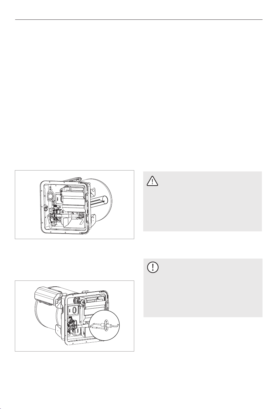
5. Remove anode rod from tank. The anode rod
is accessible at the front of the water heater.
NOTICE
Be certain to refill water heater with
water and remove all air from tank and
lines before re-lighting or before
turning on electrical power.
6.5 Draining and Storage Instructions
Replacement T & P Relief Valve Parts
Ÿ Do not install anything less than a
combination T & P relief valve certified by a
nationally recognized testing laboratory that
maintains periodic inspection of product of
listed equipment or materials, as meeting
requirements for Relief Valves and Automatic
Gas Shutoff Devices for Hot Water Supply
Systems, ANSI Z21.22. The Valve must have a
maximum set pressure not to exceed 150 PSI
(1034.21 kPa).
Water Weeping or Dripping From Pressure
Relief Valve
You may experience water weeping or
dripping from your water heater's Pressure
and Temperature (T & P) Relief Valve when
your water heater is operating. Water weeping
or dripping from the T & P Valve does not
always mean the T & P Valve is defective. As
water is heated, it expands. The water system
in a recreational vehicle is a closed system and
does not allow for the expansion of heated
water. When the pressure of the water system
exceeds the relieving point of the T & P Valve,
the valve will relieve the excess pressure.
Recommends that a check valve not be
installed directly at the inlet to the water
heater tank. This will increase weeping of the
pressure relief valve.
A T & P relief valve dripping while the Water
Heater is running does not mean it is defective.
During normal expansion of water, as it is
heated in the closed water system of an RV,
may cause the T&P relief valve to drip. The
water heater tank is designed with an internal
air gap at the top of the tank to reduce the
possibility of dripping. Over time, the
expanding water will absorb this air and it
must be restored. Due to variations in water
quality, the T&P relief valve may have a shorter
life and may need replacement within the
Water Heater warranty period. If corrosion is
detected, it will not be covered under
warranty.
Ÿ Installation must conform with local codes or
in the absence of local codes, American
National Standard for Recreational Vehicles,
ANSI A119.2/NFPA 50IC.
Ÿ Install the valve into the provided opening
marked for this purpose on the Water Heater.
Ÿ For an external electrical source, ground this
unit in accordance with National Electrical
Code ANSI/NFPA70.
27
6.7 Using After-Market Water
Heating Element Devices
WARNING: EXPLOSION AND OR BURN
INJURY.
Ÿ Do not use after-market heating
elements. After market heating
elements can lack critical safety
controls.
Ÿ Do not use bug screens, anode rods
or other non-approved devices with
this water heater.
Failure to obey the following
warnings could result in death or
serious injury:
Ÿ The use of after-market heating
elements can lead to uncontrolled
water tank heating and tank
explosion.
NOTICE
Ÿ Any alteration, such as the addition
of an after-market heating element
device, will void the warranty.
Ÿ The use of any after-market heating
element devices may result in
damage to components or the water
heater.
If your water heater plumbing system is
equipped with a bypass kit, use it to close off
the water heater, drain the water heater
completely and leave the water heater closed
off (out of the system) in the bypass position
particularly if you are introducing antifreeze
into the plumbing system. Antifreeze can be
very corrosive to the anode rod creating
premature failure and heavy sediment in the
tank. If the plumbing system is not equipped
with a bypass kit, and you intend to winterize
by adding antifreeze to the system, remove the
anode rod (storing it for the winter) and replace
it with a 3/4" drain plug.
6.6 Winterizing
Maintenance and Care
28
7 Troubleshooting
Troubleshooting
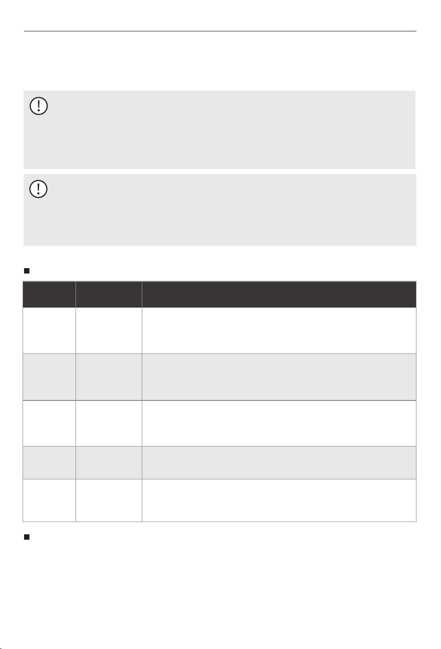
7.1 Fault Description and Troubleshooting
29
Failure name
Problem Description
Water probe
failure
The water probe is either open or short-circuited. All solenoid valves
and heating elements are shut off. The indicator light blinks once per
cycle and a continuous buzzer sounds.
Ignition / Flame
Failure
Detected failure in ignition, unexpected flame-out during operation, or
false flame signal before ignition. The gas system shuts down. The
indicator light blinks twice rapidly, and the buzzer sounds.
Valve or
Thermostat
Failure
A valve short or open circuit was detected before or during operation.
Gas operation stops. The indicator light blinks three times, and the
buzzer sounds.
Heating
Element Failure
The heating element is missing or faulty. Electric heating is disabled.
The indicator light blinks four times, accompanied by an audible alert.
Electronic
Anode Failure
A short circuit was detected in the electronic anode. Both gas and
electric heating are disabled. The system requires a power reset and
restoration of the anode before it can function again.
Fault Reset Method
2. Press the power button on the wired controller to turn off the heater.
4. If the error persists, please contact after-sales service.
3. Wait 5 seconds, then turn it back on.
1. Make sure the water and gas supplies are normal.
If any of the above error codes appear:
LED Blink
Pattern
1-time Blink
2-time Blink
3-time Blink
4-time Blink
6-time Blink
NOTICE
Ÿ If the issue is resolved and the system returns to normal, the heater may continue to operate.
Ÿ The fault indicator light refers to the power button light on the wired controller.
Ÿ The flashing of the indicator light indicates an abnormal operating condition.
Ÿ If the problem persists and the heater fails to function, please contact technical support.
Fault Codes
NOTICE: Air in the Gas Line
During the first installation or after replacing gas components, there may be residual air inside
the gas pipeline. It may take multiple ignition attempts before propane gas reaches the water
heater.
This is normal and not a malfunction. Once the air is purged, the unit should ignite and operate
properly.
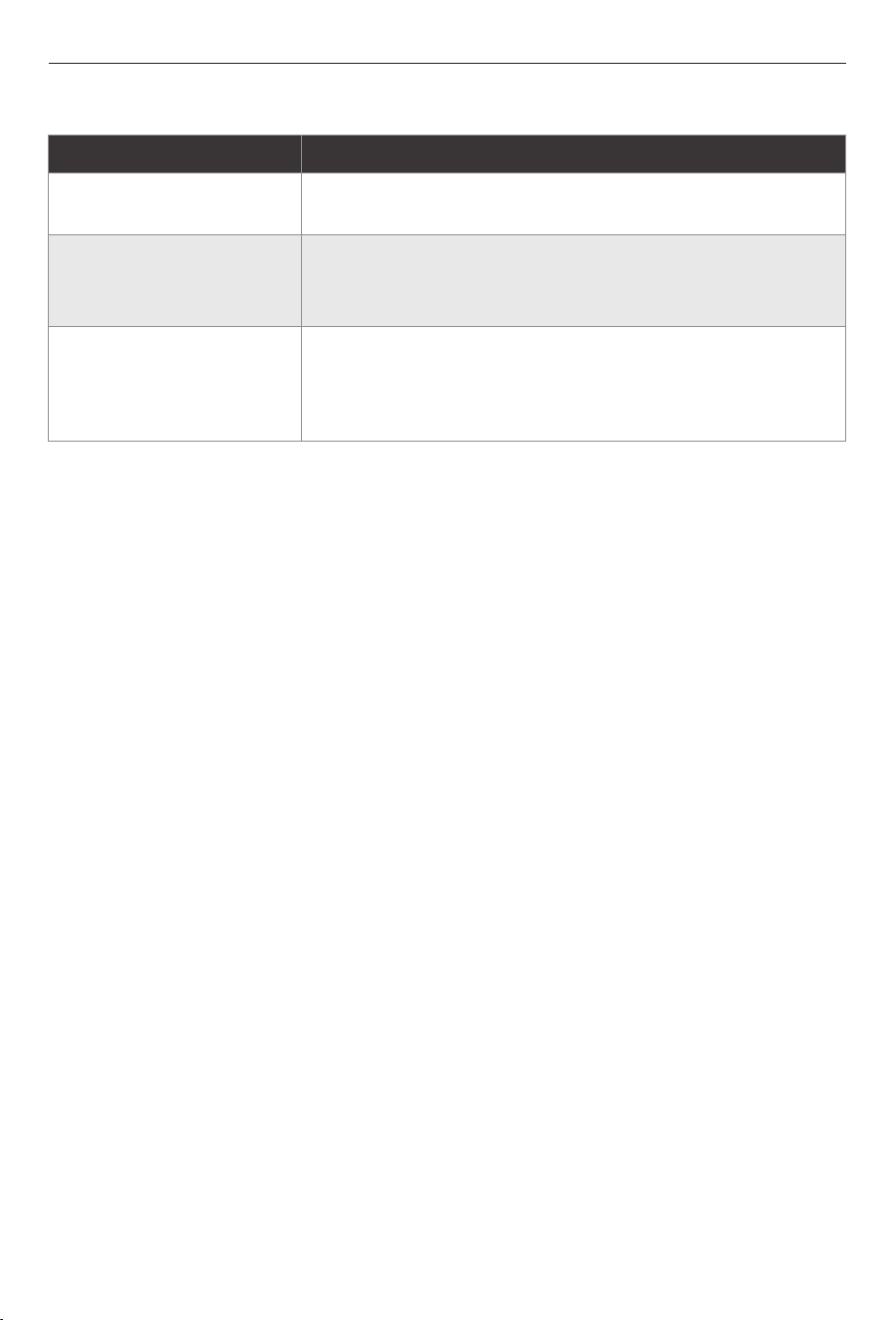
Phenomenon
Reason and handling method
White smoke at exhaust
When the outdoor temperature is too low, the exhausted smoke
encounters outdoor cold air and condenses into a white mist.
Failure to provide hot water
during winter
Please adjust the amount of water appropriately.
The water temperature is too low, the water flow exceeds the
heating capacity of the water heater.
After opening, hot water
does not come immediately
On the one hand, the time lag between the hot water valve and
machine body may be the reason. On the other hand, the
existed cold water within pipeline takes time to be showered
out, the longer the pipeline, the longer time it takes.
7.2 Non-defect When the Following Conditions Occur:
Troubleshooting
30
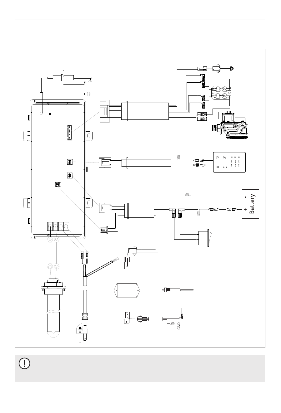
8 Wiring Diagrams
NOTICE
Label all wires prior to disconnecting when servicing controls. Wiring errors can cause
improper and dangerous operation. Verify proper operation after servicing.
FSGE-HS6, FSGE-HS10
Wiring Diagrams
Thermostat
Regulator
valve
Temperature
probe
Wired controller
Power switch
GND
GND
Ignition pin
assembly
Heating tube
DC 12V
120 VAC 60 Hz
31
Electronic titanium
rod model
Electronic titanium rods
Adapter cable
Lock
Intake
connecting
pipe
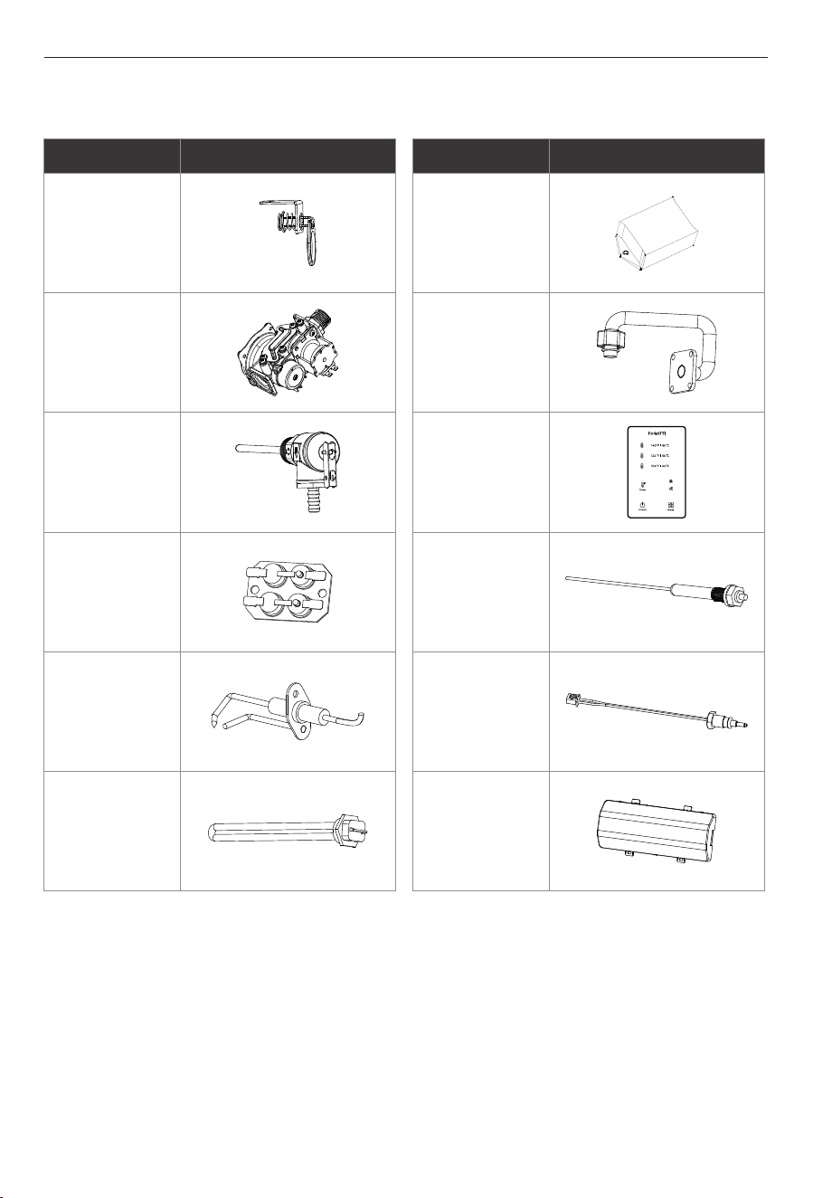
9 Replacement Parts: Components
Parts
Photo
Parts
Photo
Wired
Controller
Electronic
titanium rods
Water Outlet
temperature
probe
Burner
controller
Gas control
valve
Temperature
and Pressure
Relief Valve
Thermostat
Ignition pin
assembly
Heating pipe
Electronic
titanium
rod module
Replacement parts: components
32
Warranty Policy
What is covered
How long does coverage last
Item
All Other Parts and Components
*Shipping Costs
Period of Coverage (from date of purchase)
12 months
30 days
Residential Applications
* Which excluding Alaska, Hawaii, and any location outside of the continental US and Canada
Limitation on warranties
The Fogatti Standard Limited Warranty covers any defects in materials or workmanship when the product is
installed and operated according to Fogatti written installation instructions, subject to the terms within this
Limited Warranty document. This Limited Warranty applies only to products that are installed correctly in the
United States and Canada. Improper installation may void this Limited Warranty. Fogatti strongly recommends
that this tankless water heater to be installed by a contractor who is licensed, state qualified, and trained on
Fogatti's tankless products since improper installation may invalidate warranty coverage.
During the Warranty Period, all repair parts must be genuine Fogatti parts; all repairs or replacements must be
performed by a qualified professional who is professionally trained to do the type of repair. A component in the
product fails because of a manufacturing defect, Fogatti will repair, replace, or refund the product to the owner
at Fogatti’s sole discretion and as determined to be appropriate by the Fogatti Support Team.
No one is authorized to make any other warranties on behalf of Fogatti Corporation. Except as expressly
provided herein, there are no other warranties, expressed or implied, including, but not limited to warranties of
merchantability or fitness for a particular purpose, which extend beyond the description of the warranty herein.
Any implied warranties of merchantability and fitness arising under state law are limited in duration to the
period of coverage provided by this Limited Warranty, unless the period provided by state law is less. Some
states do not allow limitations on how long an implied Limited Warranty lasts, so the above limitation may not
apply to you. Fogatti shall not be liable for indirect, incidental, special, consequential, or other similar damages
that may arise, including lost profits, damage to person or property, loss of use, inconvenience, or liability
arising from improper installation, service, or use. Some states do not allow the exclusion or limitation of
incidental or consequential damages, so the above limitation may not apply to you. This Limited Warranty gives
you specific legal rights, and you may also have other rights which vary from state to state.
Fogatti does not authorize any person or company to assume for it any obligation or liability in connection with
the replacement of the product. If Fogatti determines that repair of a product is not possible, Fogatti may
replace the product with a comparable product at Fogatti’s sole discretion. The warranty claim for product parts
and labor may be denied if a component or product returned to Fogatti is found to be free of defects in material
or workmanship; damaged by improper installation, use or operation; or damaged during return shipping.
33

To make a warranty claim through this Limited Warranty, the owner must contact Fogatti’s Customer Service
team atservice@fogatti.com, schedule a call or live chat on the Fogatti Whatsapp. It is within Fogatti’s sole
discretion when a repair, replacement, or refund will be issued. Any return for refund must be approved by
Fogatti’s Customer Service team prior to shipping the product back to Fogatti. Please refer to Returning Your
Product for Repair or Refund Policy provided with the Product.
Ÿ Serial numbers
All shipments of any type of product coming to Fogatti for any reason must have a Return Goods Authorization
(“RGA”) number for any repairs to be made. Please contact Fogatti to obtain an RGA number prior to shipping
anything to Fogatti. Failure to do so could result in loss of product. Fogatti will not be responsible for
replacement due to loss or damage if these steps are not properly followed.
Ÿ Proof of purchase
Within the first 30 days of purchase, Fogatti will cover all ground shipping costs for warranty related issues in
the US and Canada, excluding Alaska, Hawaii, and any location outside of the continental US and Canada. After
the first 30 days of purchase, the owner is responsible for all shipping to Fogatti, regardless of reason or
circumstance. Fogatti will cover the warranty related shipping costs when returning the product to the owner
after repair/inspection. The method for warranty related shipping will be ground equivalent with the provider
within Fogatti’s sole discretion.
What information you will need for processing of your warranty claim:
Ÿ Photos of the installation
Ÿ Photos of the damage part (if there is one)
Any returns to Fogatti must be sent in the original packaging.If your returned product does not have the original
packaging and/or is missing any of the components that came with the product, there will be a nonnegotiable
15% restock fee.
How to obtain service
1. A repair, replacement, or refund will not be provided under this Limited Warranty unless the Product
containing the defective component is properly installed and maintained according to Fogatti’s Installation
Manual and Use & Care Manual and in compliance with all applicable federal, state/province, and local laws,
regulations, codes, policies, and licensing requirements. Any abuse, misuse, alteration, neglect, or
misapplication of the product will void this Limited Warranty.
3. Fogatti systems is not responsible for any expenses arising from labor services, including but not limited to,
installation or removal services due to a warranty claim.
5. A repair, replacement, or refund will not be provided if the product is damaged because of improper use,
including freezing within the unit or surrounding piping, incorrect sizing for the application, scale build up, or
incorrect gas and/or water pressure.
The following exclusions apply to this Limited Warranty:
2. A repair, replacement, or refund will not be provided if the product is damaged by services performed by
third party service providers other than Fogatti Systems.
4. A repair, replacement, or refund will not be provided if the product is damaged because of improper
installation, including sizing, length, elevation, condensation drainage, or inadequate airflow.
6. This product shall not be used as a pool or spa heater. Use of the Product as a pool or spa heater shall be
considered misuse and will void this Limited Warranty.
What Is not covered
34