Home
Bookmarks
Home
Bosch
Bosch PCT915C91N/40 User Manual
Page 2
Bosch PCT915C91N/40 Serie 6 Gas hob
User Manual - Page 2
For PCT915C91N/40.
PDF File Manual
,
16 pages
,
Read Online
|
Download pdf file
Sicherheitshinweise
Vor dem Einbau
Vorbereitung des Küchenmöbels (Abb. 1-2)
Einbau des Geräts
Hinweis
1. Schrauben Sie die Klammern in der angegebenen Position an, so dass sie sich frei drehen.
2. Fügen Sie das Kochfeld mittig ein.
3. Drehen Sie die Klammern und ziehen Sie diese fest an.
Ausbau des Kochfeldes
Gasanschluss (Abb. 5)
: Gasaustrittsgefahr!
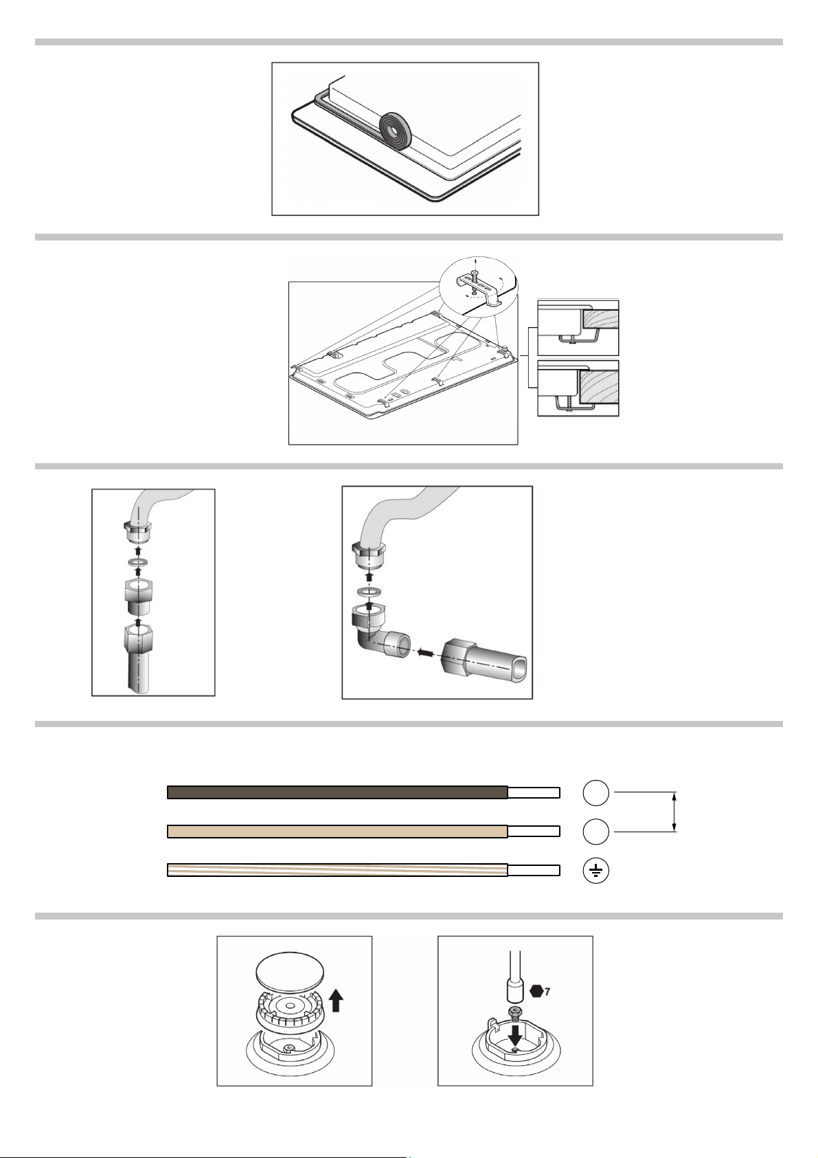
Elektrischer Anschluss (Abb. 6)
Umstellung auf eine andere Gasart
A) Austausch der Düsen (Abb. 7):
1. Nehmen Sie die Roste, Brennerdeckel und Verteiler ab.
2. Tauschen Sie die Düsen mit dem über unseren Kundendienst erhältlichen Schlüssel mit der Artikelnummer 340847 aus (für Doppelbrenner und Dreiflammenbrenner Artikelnummer 340808), siehe Tabelle I. Achten Sie dabei besonders darauf, dass die Dü...
3. Bringen Sie die Verteiler und Brennerdeckel auf den entsprechenden Kochstellen an und setzen Sie die Roste korrekt in den entsprechenden Halteelementen ein.
B) Einstellung der Gashähne
1. Drehen Sie die Bedienknebel auf die niedrigste Stufe.
2. Ziehen Sie die Bedienknebel der Gashähne ab. Abb. 8.
3. Stellen Sie die minimale Gaszufuhr ein, indem Sie die Bypass- Schraube mit einem Schlitzschraubenzieher drehen.
Achtung!
Safety precautions
Before installing
Preparation of the kitchen unit (fig. 1-2)
Installation of appliance
Note
1. Screw each one of the clips into the position indicated so that they are free to rotate.
2. Insert and centre the hob.
3. Turn the clips and tighten them fully.
Removal of hob
Gas connection (fig. 5)
: Danger of leaks!
Electric connection (fig. 6)
Changing the gas type
A) Changing the nozzles (fig. 7):
1. Remove the pan supports, burner caps and diffusers.
2. Change the nozzles using the spanner code 340847 (code 340808 for double-flame burners or triple-flame burners) provided by our Technical Assistance Service, see table I, taking special care to ensure that the nozzle does not fall when it is remov...
3. Position the diffusers and burner caps on the corresponding rings and the pan supports on their fasteners.
B) Adjusting the taps
1. Set the control knobs to minimum.
2. Remove the control knobs from the taps. Fig. 8.
3. Adjust the minimum ring setting by turning the by-pass screw using a flat head screwdriver.
Caution!
Indicaciones de seguridad
Antes de la instalación
Preparación del mueble (fig. 1-2)
Instalación del aparato
Nota
1. Atornille cada una de las grapas en la posición indicada dejando que giren libremente.
2. Encastre y centre la placa de cocción.
3. Gire las grapas y apriételas a fondo.
Desmontaje de la placa de cocción
Conexión de gas (fig. 5)
: ¡Peligro de fuga!
Conexión eléctrica (fig. 6)
Cambio del tipo de gas
A) Cambio de inyectores (fig. 7):
1. Retire las parrillas, tapas de quemador y difusores.
2. Cambie los inyectores usando la llave disponible a través de nuestro servicio técnico con código 340847 (para quemadores de doble o triple llama código 340808), ver tabla I, teniendo especial cuidado en que no se desprenda el inyector al retir...
3. Coloque los difusores y las tapas de los quemadores en sus correspondientes fuegos y las parrillas en sus elementos de sujeción.
B) Reglaje de los grifos:
1. Coloque los mandos en la posición de mínimo.
2. Retire los mandos de los grifos. Fig. 8.
3. Regule el fuego mínimo girando el tornillo bypass mediante un destornillador de punta plana.
¡Atención!
Indications de sécurité
Avant l'installation
Préparation du meuble (fig.1-2)
Installation de l'appareil
Remarque
1. Vissez chacune des agrafes dans la position indiquée en les laissant tourner librement.
2. Encastrez et centrez la plaque de cuisson.
3. Tournez les agrafes et serrez-les à fond.
Démontage de la plaque de cuisson
Branchement de gaz (fig. 5)
: Risque de fuites !
Branchement électrique (fig. 6)
Changement du type de gaz
A) Changement des injecteurs (fig. 7):
1. Retirez les grilles, les couvercles de brûleur et les diffuseurs.
2. Changez les injecteurs en utilisant la clé disponible (réf. 340847) auprès de notre Service technique (pour brûleurs double ou triple flamme, réf. 340808), cf. tableau I, en faisant particulièrement attention à ne pas déloger l'injecteur e...
3. Placez les diffuseurs et les couvercles des brûleurs sur les feux correspondants et les grilles sur leurs éléments de fixation.
B) Réglage des robinets
1. Placez les boutons de commande sur la position minimum.
2. Retirez les boutons de commande des robinets. Fig. 8.
3. Réglez le feu minimum en tournant la vis by-pass à l'aide d'un tournevis à pointe plate.
Attention !
Indicazioni di sicurezza
Prima dell'installazione
Preparazione del mobile (fig. 1-2)
Installazione dell'apparecchio
Avvertenza
1. Avvitare ognuna delle graffe nella posizione indicata, lasciandole girare liberamente.
2. Incassare e centrare il piano di cottura.
3. Girare le graffe e stringerle a fondo.
Smontaggio del piano di cottura
Attacco del gas (fig. 5)
: Pericolo di fughe!
Connessione elettrica (fig. 6)
Cambio del tipo di gas
A) Sostituzione degli iniettori (fig. 7):
1. Rimuovere le griglie, i coperchi del bruciatore e i diffusori.
2. Sostituire gli iniettori usando la chiave disponibile presso il nostro Servizio Tecnico, codice 340847 (340808 per i bruciatori a doppia o tripla fiamma); far riferimento alla tabella I, facendo particolare attenzione che l'iniettore non si distac...
3. Collocare i diffusori e i coperchi dei bruciatori sui fuochi corrispondenti e le griglie sugli appositi elementi di sostegno.
B) Regolazione dei rubinetti
1. Collocare le manopole nella posizione di minimo.
2. Estrarre le manopole dei rubinetti. Fig. 8.
3. Regolare il fuoco minimo girando la vite di by-pass con un cacciavite a punta piatta.
Attenzione!
Veiligheidsaanwijzingen
Vóór de installatie
Voorbereiding van het meubel (afb. 1-2)
Installatie van het apparaat
Aanwijzing
1. Draai elk van de klemmen in de aangeduide stand en zorg dat deze vrij draaien.
2. Bouw de kookplaat in en centreer deze.
3. Draai de klemmen helemaal aan.
Uitbouw van de kookplaat
Gasaansluiting (fig. 5)
: Lekgevaar!
Elektrische aansluiting (Afb. 6)
Verandering van gastype
A) Vervangen van de inspuiters (afb. 7):
1. Verwijder de roosters, hoedjes en verspreiders.
2. Vervang de inspuiters met de sleutel die beschikbaar is via onze technische dienst, met code 340847 (voor branders met dubbele of driedubbele vlam code 340808), zie tabel I. Zorg dat de inspuiter niet losraakt bij het verwijderen of bevestigen hie...
3. Plaats de diffusors en de deksels van de branders op de bijbehorende pitten en de roosters op de bevestigingselementen.
B) Afstelling van de kranen
1. Zet de knoppen in de laagste stand.
2. Haal de knoppen van de kranen af. Afb.8.
3. Stel de minimumstand af door de bypass bout te draaien met een schroevendraaier met een vlakke punt.
Attentie!
Wskazówki dotyczące bezpieczeństwa
Przed zainstalowaniem
Przygotowanie mebla (rys. 1-2)
Instalacja urządzenia
Wskazówka
1. Przykręcić każdy z uchwytów we wskazanej pozycji, tak by obracały się swobodnie.
2. Wsunąć płytę kuchenki i ustawić centralnie w wycięciu mebla.
3. Obrócić uchwyty i docisnąć je do końca.
Demontaż płyty kuchenki
Podłączanie gazu (rys. 5)
: Niebezpieczeństwo ulatniania się gazu!
Podłączanie prądu (rys. 6)
Zmiana rodzaju gazu
A) Wymiana dyszy (Rys. 7):
1. Zdjąć ruszty, nakładki palnika i dyfuzory.
2. Wymienić dysze za pomocą klucza dostępnego w naszym Serwisie Technicznym (kod produktu 340847, natomiast w przypadku palników o podwójnym lub potrójnym wieńcu płomieni - kod produktu 340808), patrz tabela I, zwracając szczególną uwagę ...
3. Założyć dyfuzory i nakładki palników na odpowiednich palnikach i rusztach, na właściwych elementach mocujących.
B) Regulacja kurków gazu
1. Ustawić wszystkie pokrętła w położeniu minimalnym.
2. Wyjąć pokrętła z kurków. Rys. 8.
3. Wyregulować płomień minimalny, obracając śrubę złączki przejściowej za pomocą śrubokrętu z płaską końcówką.
Uwaga!
Indicações de segurança
Antes da instalação
Preparação do móvel (fig. 1-2)
Instalação do aparelho
Nota
1. Aparafuse cada um dos grampos na posição indicada, deixando que estes rodem livremente.
2. Encastre e centre a placa de cozedura.
3. Gire os grampos e aperte-os bem.
Desmontagem da placa de cozedura
Ligação a gás (fig. 5)
: Perigo de fuga!
Ligação eléctrica (fig. 6)
Mudança do tipo de gás
A) Substituição dos injectores (fig. 7):
1. Retire as grelhas, as tampas de queimador e os difusores.
2. Substitua os injectores usando a chave disponibilizada pelo nosso serviço de assistência técnica, com o código 340847 (para queimadores de chama dupla ou tripla, código 340808) (ver tabela I), tendo especial atenção para que o injector não...
3. Coloque os difusores e as tampas dos queimadores nos respectivos lugares e as grelhas nos respectivos elementos de fixação.
B) Regulação das torneiras
1. Coloque os comandos na sua posição mínima.
2. Retire os comandos das torneiras. Fig. 8.
3. Regule a chama mínima rodando o parafuso bypass através de uma chave de fendas de ponta plana.
Atenção!
Правила техники безопасности
Перед началом установки
Подготовка тумбы (рис. 1-2)
Монтаж прибора
Указание
1. Привинтите все зажимы в нужном положении так, чтобы они могли свободно вращаться.
2. Вставьте варочную панель в подготовленное отверстие и выровняйте ее.
3. Разверните зажимы и туго затяните их.
Демонтаж варочной панели
Подключение газа (рис. 5)
: Существует опасность утечки газа!
Подключение к электросети (рис. 6)
Адаптация к другому виду газа
A) Замена жиклеров (рис. 7):
1. Снимите решетки, крышки горелок и рассекатели.
2. Замените жиклеры с помощью ключа, имеющегося в продаже в нашем сервисном центре, артикул 340847 (Конфорка двойного или тройного пламени а...
3. Установите рассекатели и крышки горелок на соответствующие конфорки, а решетки — на соответствующие опорные элементы.
B) Регулировка кранов
1. Установите ручки управления в положение минимального пламени.
2. Снимите ручки кранов (рис. 8).
3. Отрегулируйте минимальную величину пламени, повернув байпасный винт с помощью плоской отвертки.
Внимание!
Güvenlik önerileri
Kurulumdan önce
Mobilyanın hazırlanması (şekil 1-2)
Cihazın kurulumu
Bilgi
1. Kıskaçları rahatça dönebilmelerini sağlayarak belirtilen pozisyonda vidalayınız.
2. Yerleştiriniz ve pişirme tezgahını ortalayınız.
3. Kıskaçları döndürünüz ve sıkıca vidalayınız.
Cihazın sökülmesi
Gazlı bağlantı (şek. 5)
: Sızıntı tehlikesi!
Elektrikli bağlantı (şekil 6)
Gaz tipinin değiştirilmesi
A) Brülör ucunun değiştirilmesi (şek. 7):
1. Izgaraları, brülör kapaklarını ve alev dağıtıcıları çıkarınız.
2. Teknik Servisimizden 340847 kod numarası ile temin edilebilecek olan anahtarı kullanarak brülör uçlarını değiştiriniz (çift alevli brülörler için kod numarası 340808), bkz tablo I, brülöre takarken veya çıkarırken brülör ucunu...
3. Alev dağıtıcıları ve brülör kapaklarını ilgili kısımlarına ve ızgaraları tespit elemanlarına takınız.
B) Vanaların ayarlanması
1. Kumanda düğmelerini minimum konumuna getiriniz.
2. Vanaların kumanda düğmelerini çıkartınız. Şekil 8.
3. Düz uçlu tornavida ile by-pass vidasını çevirerek en düşük alevi ayarlayınız.
Dikkat!
Page 2/16
Page 1
Page 2
Page 3
Page 4
Page 5
Page 6
Page 7
Page 8
Page 9
Page 10
Page 11
Page 12
Page 13
Page 14
Page 15
Page 16
Contents
Table of Contents
Search
Previous
Next
Bookmarks
Loading ...
D
/
9
9
99
1
a
Loading ...
Loading ...
Loading ...
File type: PDF
File name: 16742187_pct915c91n-01.pdf
File size: 1.92 MB
File Language: English
Pages: 16
Author: Bosch
File created: 2015-06-29
Published: 2023-12-07
Updated: 2023-12-07
Download File
Table of Contents
×
Sicherheitshinweise
3
Vor dem Einbau
3
Vorbereitung des Küchenmöbels (Abb. 1-2)
3
Einbau des Geräts
4
Hinweis
4
1. Schrauben Sie die Klammern in der angegebenen Position an, so dass sie sich frei drehen.
4
2. Fügen Sie das Kochfeld mittig ein.
4
3. Drehen Sie die Klammern und ziehen Sie diese fest an.
4
Ausbau des Kochfeldes
4
Gasanschluss (Abb. 5)
4
: Gasaustrittsgefahr!
4
Elektrischer Anschluss (Abb. 6)
4
Umstellung auf eine andere Gasart
4
A) Austausch der Düsen (Abb. 7):
4
1. Nehmen Sie die Roste, Brennerdeckel und Verteiler ab.
4
2. Tauschen Sie die Düsen mit dem über unseren Kundendienst erhältlichen Schlüssel mit der Artikelnummer 340847 aus (für Doppelbrenner und Dreiflammenbrenner Artikelnummer 340808), siehe Tabelle I. Achten Sie dabei besonders darauf, dass die Dü...
4
3. Bringen Sie die Verteiler und Brennerdeckel auf den entsprechenden Kochstellen an und setzen Sie die Roste korrekt in den entsprechenden Halteelementen ein.
4
B) Einstellung der Gashähne
4
1. Drehen Sie die Bedienknebel auf die niedrigste Stufe.
4
2. Ziehen Sie die Bedienknebel der Gashähne ab. Abb. 8.
4
3. Stellen Sie die minimale Gaszufuhr ein, indem Sie die Bypass- Schraube mit einem Schlitzschraubenzieher drehen.
4
Achtung!
4
Safety precautions
4
Before installing
4
Preparation of the kitchen unit (fig. 1-2)
5
Installation of appliance
5
Note
5
1. Screw each one of the clips into the position indicated so that they are free to rotate.
5
2. Insert and centre the hob.
5
3. Turn the clips and tighten them fully.
5
Removal of hob
5
Gas connection (fig. 5)
5
: Danger of leaks!
5
Electric connection (fig. 6)
5
Changing the gas type
5
A) Changing the nozzles (fig. 7):
5
1. Remove the pan supports, burner caps and diffusers.
5
2. Change the nozzles using the spanner code 340847 (code 340808 for double-flame burners or triple-flame burners) provided by our Technical Assistance Service, see table I, taking special care to ensure that the nozzle does not fall when it is remov...
5
3. Position the diffusers and burner caps on the corresponding rings and the pan supports on their fasteners.
5
B) Adjusting the taps
5
1. Set the control knobs to minimum.
5
2. Remove the control knobs from the taps. Fig. 8.
5
3. Adjust the minimum ring setting by turning the by-pass screw using a flat head screwdriver.
5
Caution!
5
Indicaciones de seguridad
5
Antes de la instalación
6
Preparación del mueble (fig. 1-2)
6
Instalación del aparato
6
Nota
6
1. Atornille cada una de las grapas en la posición indicada dejando que giren libremente.
6
2. Encastre y centre la placa de cocción.
6
3. Gire las grapas y apriételas a fondo.
6
Desmontaje de la placa de cocción
6
Conexión de gas (fig. 5)
6
: ¡Peligro de fuga!
6
Conexión eléctrica (fig. 6)
6
Cambio del tipo de gas
6
A) Cambio de inyectores (fig. 7):
6
1. Retire las parrillas, tapas de quemador y difusores.
6
2. Cambie los inyectores usando la llave disponible a través de nuestro servicio técnico con código 340847 (para quemadores de doble o triple llama código 340808), ver tabla I, teniendo especial cuidado en que no se desprenda el inyector al retir...
6
3. Coloque los difusores y las tapas de los quemadores en sus correspondientes fuegos y las parrillas en sus elementos de sujeción.
6
B) Reglaje de los grifos:
6
1. Coloque los mandos en la posición de mínimo.
6
2. Retire los mandos de los grifos. Fig. 8.
6
3. Regule el fuego mínimo girando el tornillo bypass mediante un destornillador de punta plana.
6
¡Atención!
6
Indications de sécurité
6
Avant l'installation
7
Préparation du meuble (fig.1-2)
7
Installation de l'appareil
7
Remarque
7
1. Vissez chacune des agrafes dans la position indiquée en les laissant tourner librement.
7
2. Encastrez et centrez la plaque de cuisson.
7
3. Tournez les agrafes et serrez-les à fond.
7
Démontage de la plaque de cuisson
7
Branchement de gaz (fig. 5)
7
: Risque de fuites !
7
Branchement électrique (fig. 6)
7
Changement du type de gaz
7
A) Changement des injecteurs (fig. 7):
7
1. Retirez les grilles, les couvercles de brûleur et les diffuseurs.
7
2. Changez les injecteurs en utilisant la clé disponible (réf. 340847) auprès de notre Service technique (pour brûleurs double ou triple flamme, réf. 340808), cf. tableau I, en faisant particulièrement attention à ne pas déloger l'injecteur e...
7
3. Placez les diffuseurs et les couvercles des brûleurs sur les feux correspondants et les grilles sur leurs éléments de fixation.
7
B) Réglage des robinets
7
1. Placez les boutons de commande sur la position minimum.
7
2. Retirez les boutons de commande des robinets. Fig. 8.
7
3. Réglez le feu minimum en tournant la vis by-pass à l'aide d'un tournevis à pointe plate.
7
Attention !
8
Indicazioni di sicurezza
8
Prima dell'installazione
8
Preparazione del mobile (fig. 1-2)
8
Installazione dell'apparecchio
8
Avvertenza
8
1. Avvitare ognuna delle graffe nella posizione indicata, lasciandole girare liberamente.
8
2. Incassare e centrare il piano di cottura.
8
3. Girare le graffe e stringerle a fondo.
8
Smontaggio del piano di cottura
8
Attacco del gas (fig. 5)
8
: Pericolo di fughe!
8
Connessione elettrica (fig. 6)
8
Cambio del tipo di gas
8
A) Sostituzione degli iniettori (fig. 7):
8
1. Rimuovere le griglie, i coperchi del bruciatore e i diffusori.
8
2. Sostituire gli iniettori usando la chiave disponibile presso il nostro Servizio Tecnico, codice 340847 (340808 per i bruciatori a doppia o tripla fiamma); far riferimento alla tabella I, facendo particolare attenzione che l'iniettore non si distac...
8
3. Collocare i diffusori e i coperchi dei bruciatori sui fuochi corrispondenti e le griglie sugli appositi elementi di sostegno.
9
B) Regolazione dei rubinetti
9
1. Collocare le manopole nella posizione di minimo.
9
2. Estrarre le manopole dei rubinetti. Fig. 8.
9
3. Regolare il fuoco minimo girando la vite di by-pass con un cacciavite a punta piatta.
9
Attenzione!
9
Veiligheidsaanwijzingen
9
Vóór de installatie
9
Voorbereiding van het meubel (afb. 1-2)
9
Installatie van het apparaat
9
Aanwijzing
9
1. Draai elk van de klemmen in de aangeduide stand en zorg dat deze vrij draaien.
9
2. Bouw de kookplaat in en centreer deze.
9
3. Draai de klemmen helemaal aan.
9
Uitbouw van de kookplaat
9
Gasaansluiting (fig. 5)
9
: Lekgevaar!
9
Elektrische aansluiting (Afb. 6)
9
Verandering van gastype
10
A) Vervangen van de inspuiters (afb. 7):
10
1. Verwijder de roosters, hoedjes en verspreiders.
10
2. Vervang de inspuiters met de sleutel die beschikbaar is via onze technische dienst, met code 340847 (voor branders met dubbele of driedubbele vlam code 340808), zie tabel I. Zorg dat de inspuiter niet losraakt bij het verwijderen of bevestigen hie...
10
3. Plaats de diffusors en de deksels van de branders op de bijbehorende pitten en de roosters op de bevestigingselementen.
10
B) Afstelling van de kranen
10
1. Zet de knoppen in de laagste stand.
10
2. Haal de knoppen van de kranen af. Afb.8.
10
3. Stel de minimumstand af door de bypass bout te draaien met een schroevendraaier met een vlakke punt.
10
Attentie!
10
Wskazówki dotyczące bezpieczeństwa
10
Przed zainstalowaniem
10
Przygotowanie mebla (rys. 1-2)
10
Instalacja urządzenia
10
Wskazówka
10
1. Przykręcić każdy z uchwytów we wskazanej pozycji, tak by obracały się swobodnie.
10
2. Wsunąć płytę kuchenki i ustawić centralnie w wycięciu mebla.
10
3. Obrócić uchwyty i docisnąć je do końca.
10
Demontaż płyty kuchenki
10
Podłączanie gazu (rys. 5)
10
: Niebezpieczeństwo ulatniania się gazu!
11
Podłączanie prądu (rys. 6)
11
Zmiana rodzaju gazu
11
A) Wymiana dyszy (Rys. 7):
11
1. Zdjąć ruszty, nakładki palnika i dyfuzory.
11
2. Wymienić dysze za pomocą klucza dostępnego w naszym Serwisie Technicznym (kod produktu 340847, natomiast w przypadku palników o podwójnym lub potrójnym wieńcu płomieni - kod produktu 340808), patrz tabela I, zwracając szczególną uwagę ...
11
3. Założyć dyfuzory i nakładki palników na odpowiednich palnikach i rusztach, na właściwych elementach mocujących.
11
B) Regulacja kurków gazu
11
1. Ustawić wszystkie pokrętła w położeniu minimalnym.
11
2. Wyjąć pokrętła z kurków. Rys. 8.
11
3. Wyregulować płomień minimalny, obracając śrubę złączki przejściowej za pomocą śrubokrętu z płaską końcówką.
11
Uwaga!
11
Indicações de segurança
11
Antes da instalação
11
Preparação do móvel (fig. 1-2)
11
Instalação do aparelho
12
Nota
12
1. Aparafuse cada um dos grampos na posição indicada, deixando que estes rodem livremente.
12
2. Encastre e centre a placa de cozedura.
12
3. Gire os grampos e aperte-os bem.
12
Desmontagem da placa de cozedura
12
Ligação a gás (fig. 5)
12
: Perigo de fuga!
12
Ligação eléctrica (fig. 6)
12
Mudança do tipo de gás
12
A) Substituição dos injectores (fig. 7):
12
1. Retire as grelhas, as tampas de queimador e os difusores.
12
2. Substitua os injectores usando a chave disponibilizada pelo nosso serviço de assistência técnica, com o código 340847 (para queimadores de chama dupla ou tripla, código 340808) (ver tabela I), tendo especial atenção para que o injector não...
12
3. Coloque os difusores e as tampas dos queimadores nos respectivos lugares e as grelhas nos respectivos elementos de fixação.
12
B) Regulação das torneiras
12
1. Coloque os comandos na sua posição mínima.
12
2. Retire os comandos das torneiras. Fig. 8.
12
3. Regule a chama mínima rodando o parafuso bypass através de uma chave de fendas de ponta plana.
12
Atenção!
12
Правила техники безопасности
12
Перед началом установки
12
Подготовка тумбы (рис. 1-2)
13
Монтаж прибора
13
Указание
13
1. Привинтите все зажимы в нужном положении так, чтобы они могли свободно вращаться.
13
2. Вставьте варочную панель в подготовленное отверстие и выровняйте ее.
13
3. Разверните зажимы и туго затяните их.
13
Демонтаж варочной панели
13
Подключение газа (рис. 5)
13
: Существует опасность утечки газа!
13
Подключение к электросети (рис. 6)
13
Адаптация к другому виду газа
13
A) Замена жиклеров (рис. 7):
13
1. Снимите решетки, крышки горелок и рассекатели.
13
2. Замените жиклеры с помощью ключа, имеющегося в продаже в нашем сервисном центре, артикул 340847 (Конфорка двойного или тройного пламени а...
13
3. Установите рассекатели и крышки горелок на соответствующие конфорки, а решетки — на соответствующие опорные элементы.
13
B) Регулировка кранов
13
1. Установите ручки управления в положение минимального пламени.
13
2. Снимите ручки кранов (рис. 8).
13
3. Отрегулируйте минимальную величину пламени, повернув байпасный винт с помощью плоской отвертки.
13
Внимание!
13
Güvenlik önerileri
13
Kurulumdan önce
14
Mobilyanın hazırlanması (şekil 1-2)
14
Cihazın kurulumu
14
Bilgi
14
1. Kıskaçları rahatça dönebilmelerini sağlayarak belirtilen pozisyonda vidalayınız.
14
2. Yerleştiriniz ve pişirme tezgahını ortalayınız.
14
3. Kıskaçları döndürünüz ve sıkıca vidalayınız.
14
Cihazın sökülmesi
14
Gazlı bağlantı (şek. 5)
14
: Sızıntı tehlikesi!
14
Elektrikli bağlantı (şekil 6)
14
Gaz tipinin değiştirilmesi
14
A) Brülör ucunun değiştirilmesi (şek. 7):
14
1. Izgaraları, brülör kapaklarını ve alev dağıtıcıları çıkarınız.
14
2. Teknik Servisimizden 340847 kod numarası ile temin edilebilecek olan anahtarı kullanarak brülör uçlarını değiştiriniz (çift alevli brülörler için kod numarası 340808), bkz tablo I, brülöre takarken veya çıkarırken brülör ucunu...
14
3. Alev dağıtıcıları ve brülör kapaklarını ilgili kısımlarına ve ızgaraları tespit elemanlarına takınız.
14
B) Vanaların ayarlanması
14
1. Kumanda düğmelerini minimum konumuna getiriniz.
14
2. Vanaların kumanda düğmelerini çıkartınız. Şekil 8.
14
3. Düz uçlu tornavida ile by-pass vidasını çevirerek en düşük alevi ayarlayınız.
14
Dikkat!
14
Search:
×
Search