Loading ...
Loading ...
Loading ...
ASSEMBLY INSTRUCTIONS
8
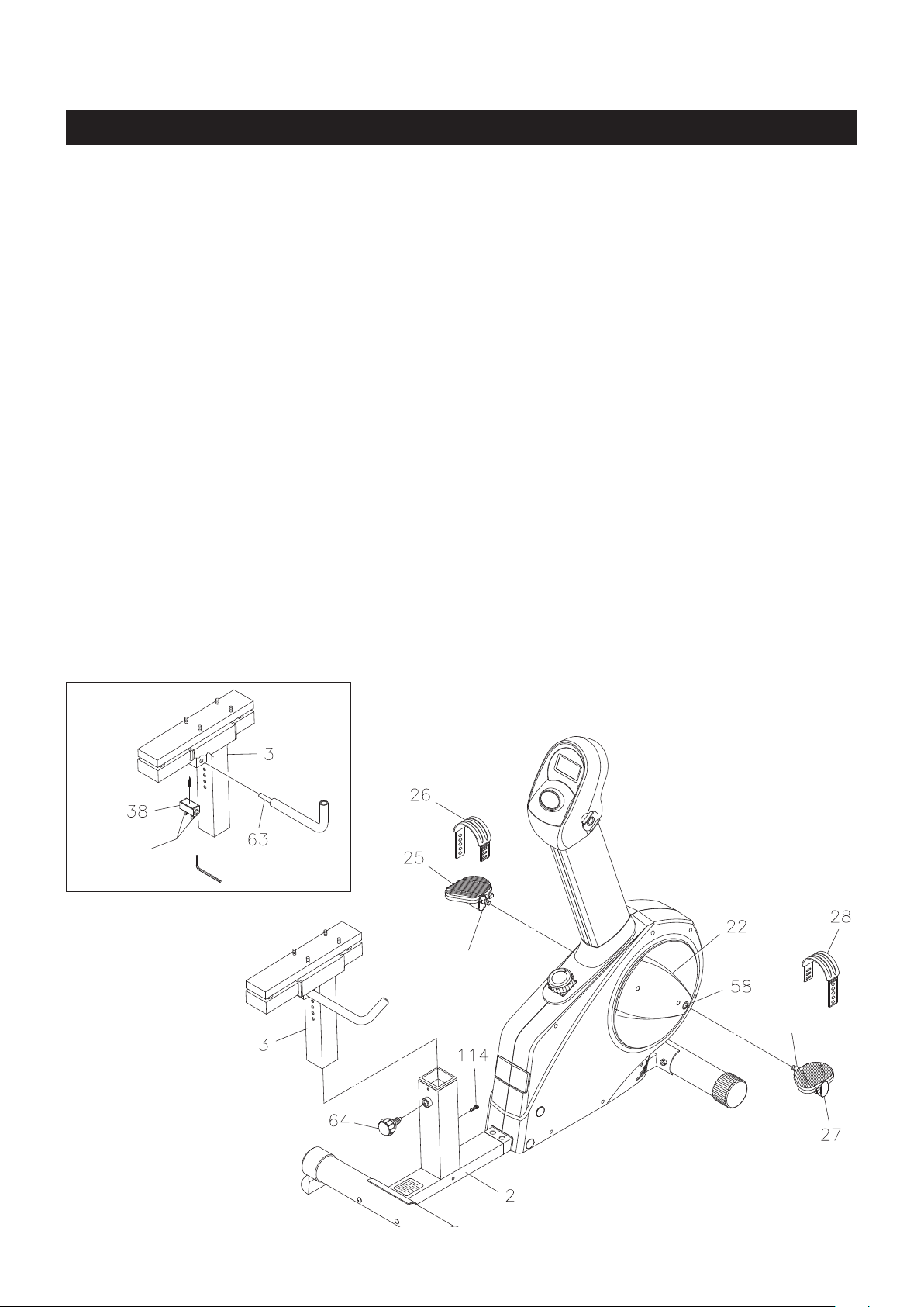
Thread the RIGHT PEDAL(27) into the RIGHT CRANK(58) located inside the CRANK COVER(22) as
shown. Tighten the pedal securely. The shoulder of the PEDALS(25, 27) should be in contact with the
CRANKS(57, 58) when securely tightened. Select the RIGHT PEDAL STRAP(28) which has R marked
on the bottom side of the strap. Snap the three hole end onto the inside edge of the RIGHT PEDAL(27).
Snap the other end onto the outside edge of the RIGHT PEDAL(27) with the R mark on the bottom of the
RIGHT PEDAL STRAP(28). Select adjustment holes which allow your foot to be easily removed from the
pedals. Use the same procedure to attach the LEFT PEDAL(25) into the LEFT CRANK(57) and snap the
LEFT PEDAL STRAP(26) onto the LEFT PEDAL(25).
STEP 4
NOTE: The RIGHT PEDAL(27) has R stamped on the end of the pedal shaft. The RIGHT PEDAL(27) has
right hand threads and is tightened by turning clockwise. The LEFT PEDAL(25) has L stamped on
the end of the pedal shaft. The LEFT PEDAL(25) has left hand threads and is tightened by turning
counterclockwise.
Allen Wrench
(98)
Set Screws
STEP 5: Refer to the inset drawing. Insert the ADJUSTMENT BLOCK(38) into the SEAT POST(3). Insert
the SEAT ADJUSTMENT LEVER(63) through the SEAT POST(3) and ADJUSTMENT BLOCK(38) and
secure by tightening the SET SCREWS(M6x1x15mm)(98) inside the ADJUSTMENT BLOCK(38) with
Allen Wrench.
STEP 6: Insert the SEAT POST(3) into the REAR FRAME(2). Then Insert the SOCKET HEAD BOLT
(M6x1x15mm)(114) through the upright tube of REAR FRAME(2) and bolt onto the SEAT POST(3). Screw
the SPRING KNOB(64) into the REAR FRAME(2) to secure the SEAT POST(3) in position.
NOTE: The pin on the SPRING KNOB(64) must be inserted into one of the adjustment holes in the SEAT
POST(3). The SPRING KNOB(64) should be screwed in tight to make the SEAT POST(3) t
securely in the REAR FRAME(2).
Shoulder
Shoulder
Loading ...
Loading ...
Loading ...