Sz:_AJ_
OWNER'S
MANUAL
MODELNO.
315.275061
CAUTION:
Read Rules for
Safe Operation
and All Instruc-
tions Carefully
CRRFTSMRN°
Industrial Electronic
Plunge Router
Double Insulated
Thank You for Buying
Craftsman Tools
Warranty
Introduction
Unpacking
Features
Adjustments
Operation
Maintenance
, Repair Parts
Sold only by
SEARS, ROEBUCK AND CO., Hoffman Estates, IL 60179
®
972000-092 Printed In U.S.A.
3-95
FULL ONE YEAR WARRANTY ON CRAFTSMAN INDUSTRIAL ELECTRONIC PLUNGE ROUTER
If this Craftsman Industrial Electronic Plunge Router fails due to a defect in material or workmanship within one year
from the date of purchase, Sears will repair it free of charge. This warranty applies only while this product is in use
in the United States, WARRANTY SERVICE IS AVAILABLE BY SIMPLY RETURNING THE TOOL TO THE
NEAREST SEARS STORE OR SERVICE CENTER THROUGHOUT THE UNITED STATES,
This warranty gives you specific legal rights, and you may also have other rights which vary from state to state.
SEARS, ROEBUCK AND CO.
DEPT. 817 WA
HQFFMAN ESTATES, IL 60179
INTRODUCTION
DOUBLE INSULATION is a concept in safety, in electric IMPORTANT - Servicing of a tool with double insulation
power tools, which eliminates the need for the usual three requires extreme care and knowledge of the system and
wire grounded power cord and grounded supply system, should be performed only by a qualified service technician.
Wherever there is electric current in the tool there are two For service we suggest you return the tool to your nearest
complete sets of insulation to protect the user. All exposed Sears Store for repair. Always use original factory replace-
metal parts are isolated from internal metal motor compo- ment parts when servicing.
nents with pretecting insulation.
RULES FOR SAFE OPERATION
READ ALL INSTRUCTIONS
1. KNOW YOUR POWER TOOL - Read owner's manual carefully. Learn its applications and limitations as well as the
specific potential hazards related to this tool.
2. GUARD AGAINST ELECTRICAL SHOCK BY PREVENTING BODY CONTACT WITH GROUNDED SURFACES.
For example: P!pes, radiators, ranges, refrigerator enclosures.
3. KEEP GUARDS IN PLACE and inworking order.
4. KEEP WORK AREA CLEAN. Cluttered areas and benches invite accidents.
5. AVOID DANGEROUS ENVIRONMENT. Don't use power tool indamp or wet locations or expose to rain. Keep work
area well lit.
6. KEEP CHILDREN AND VISITORS AWAY. All visitors should wear safety glasses and be kept a safe distance
from work area. Do not let visitors contact tool or extension cord.
7. STOREIDLETOOLS. When not in use tools shouid be stored in a dry, high or locked-up place -out of the reach of
children.
8. DON'T FORCE TOOL. Itwilldothejobbetterandsaferattherateforwhichitwasdesigned.
9. USE RIGHT TOOL. Don't force small tool or attachment todo the job of a heavy duty tool. Don't use tool forpurpose
not intended -for example - Don't use a circular saw for cutting tree limbs or logs.
10. WEAR PROPER APPAREL. No loose clothing or jewelry to get caught in moving parts. Rubber gloves and non-
skid footwear are recommended when working outdoors. Also, wear protective hair covering to contain longhair and
keep it from being drawn into air vents.
lt. ALWAYS WEAR SAFETY GLASSES. Everyday eyeglasses have only impact-resistant lenses; they are NOT
safety glasses.
12. PROTECT YOUR LUNGS. Wear a face or dust mask if operation is dusty.
13. PROTECT YOUR HEARING. Wear hearing protection during extended periods of operation.
14, DON'T ABUSE CORD. Never carry tool by cord or yank it to disconnect from receptacle. Keep cord from heat, oil
and sharp edges,
Page 2
RULES FOR SAFE OPERATION (Continued)
15. SECURE WORK. Use clamps or a vise to hold work. Both hands are needed to operate the tool,
16. DON'T OVERREACH. Keep properfooting and balance at all times, Do not use ona ladder orunstable support
17. MAINTAIN TOOLS WITH CARE. Keep tools sharp at all times, and clean for best and safest performance. Follow
instructionsfor lubricating and changing accessories.
i! 18. DISCONNECT TOOLS. When not in use, before servicing, or when changing attachments, blades, bits, cutters,
etc,, all tools should be disconnected from power supply.
19. REMOVE ADJUSTING KEYS AND WRENCHES. Form habit of checkingto see that keys and adjusting wrenches
are removed from tool before turning iton.
20. AVOID ACCIDENTAL STARTING. Don't carry plugged-in tools with finger on switch, Be sure switch is off when
plugging in.
21. MAKE SURE YOUR EXTENSION CORD 13IN GOOD CONDITION. When using an extension cord, be sure to use
one heavy enough to carry the current your product will draw. An undersized cord will cause a drop in line voltage
resulting in loss of power and overheating. A wire gauge size (A.W,G.) of at least 14 is recommended for an
extension cord 25 feet or less in length, A cord exceeding 25 feet is not recommended. If in doubt, use th next
heavier gage. The smaller the gage number, the heavier the cord.
22. OUTDOOR USE EXTENSION CORDS. When tool is used outdoors, use only extension cords suitable for use
outdoors. Outdoor approved cords are marked with the suffix W-A, for example - SJTW-A or SJOW-A.
23, KEEP CUTTERS CLEAN AND SHARP. Sharp cutters minimize stalling and kickback,
24. KEEP HANDS AWAY FROM CUTTING AREA. Keep hands away from cutters. Do not reach underneath work
while cutter is rotating, Do not attempt to remove material while cutter is rotating.
25, NEVER USE IN AN EXPLOSIVE ATMOSPHERE. Normal sparking of the motor could ignite fumes.
26. INSPECT TOOL CORDS PERIODICALLY and if damaged, have repaired at your nearest Sears Repair Center.
Stay constantly aware of cord location,
27. INSPECT EXTENSION CORDS PERIODICALLY and replace ifdamaged,
28, KEEP HANDLES DRY, CLEAN, AND FREE FROM OIL AND GREASE. Always use a clean cloth when cleaning,
Never use brake fluids, gasoline, petroleum-based products or any strong solvents to clean your tool.
29. STAY ALERT. Watch what you are doing and use common sense. Do not operate tool when you are tired. Do not
rush.
30. CHECK DAMAGED PARTS. Before further use of the tool, a guard or other part that is damaged should be carefully
checked to determine that it will operate properly and perform its intended function. Check for alignment of moving
parts, binding of moving parts, breakage of parts, mounting, and any other conditions that may affect its operation. A
guard or other part that is damaged should be properly repaired or replaced by an authorized service center unless
indicated elsewhere in this instruction manual.
31. DO NOT USE TOOL IF SWITCH DOES NOT TURN IT ON AND OFF. Have defective switches replaced by an
authorized service center.
32. Inspect for and remove all nails from lumber before routing.
DRUGS, ALCOHOL, MEDICATION. Do not operate tool while under the influence of drugs, alcohol, or any
medication.
When servicing use only identicat Craftsman replacement parts.
35. POLARIZED PLUGS. To reduce the risk of electric shock, this tool has a polarized plug (one blade is wider than the
other). This plug will fit in a polarized outlet only one way. If the plug does not fit fully inthe outlet, reverse the plug.
If it still does not fit, contact a qualified electrician to install the proper outlet. Do not change the plug in any way.
36. DO NOT USE TOOL UNDER "BROWN-OUT" OR OTHER LOW VOLTAGE CONDITIONS. Also, do not use with
any device that could cause the power supply voltage to change.
37. WHEN USING THIS ROUTER WITH A ROUTER TABLE, HELP PREVENT POSSIBLE SERIOUS INJURY BY
KEEPING THE CUTTER GUARDED AT ALL TIMES. Use only router tables, with guards, that have been designed
for use on reuters that are of this type, size, and weight.
38, SAVE THESE INSTRUCTIONS. Review them frequently and use them to instruct others who may use this tool. If
you loan someone this tool, loan them these instructions also.
Page 3
33.
34.
UNPACKING
Your new plunge router comes fully assembled. After removing it from the box, inspect itcarefully to make sure that it isnot
damaged and that no parts are missing. See Figure 1. The following accessories should also be included in the box:
1_ Combination Wrench (3/8"- 7/8") 4, Roller(Contour) Guide
2. 1/4"Adapter 5. Guide Bushing
3. Edge Guide
FEATURES
Your electronic router isa versatile woodworking toot which will give you years of trouble-free performance. It isengineered
with the professional in mind, but its ease of operation allows the amateur to produce work which is beautiful and precise.
3.5 HORSEPOWER MOTOR
Your router has a powerful 3.5 horsepower motor with suffi-
cient power to handle the toughest routing jobs. The motor
also has externally accessible brushes for ease of servicing.
SOFT START
The soft start feature builds motor RPM gradually tominimize
start-up torque. Pressing or releasing the "on-oft" trigger will
turn your router on or off.
DEPTH CONTROL KNOB
A largedepth control knob makes precise depth ofcut changes
possible. It also is very helpful when making depth of cut
changes with your router mounted upside down on a router
table.
DEPTH STOP SYSTEM
The depth stop block located on the base of your router
provides three adjustable stops and three fixed stops for
quick depth of cut changes. A depth adjustment scale makes
quick adjustments to depth of cut changes possible. The
spring loaded adjustment knob quick releases stop bar by
depressing center of knob.
1/4" AND 1/2" SHANK CAPACITY
Your router has a 1/2" diameter collet that accepts cutters
with 1/2" shanks. An adapter has been provided so that
cutters with 1/4" shank bits can also be used,
CHIP SHIELD
A clear plastic see-through chip shield has been provided on
the base of your router for protection against flying dust and
chips. It is designed to fit the front opening of the router base,
POSiLOCK SPINDLE LOCK
A posilock spindle lock secures the spindle so that only one
wrench is needed to loosen collet nut and change cutters. A
spindle lock indicator light alerts you that spindle is locked if
you connect router to power supply before unlocking spindle.
NOTE: Your router wilt not run if spindle is locked.
"LOCK-ON" FEATURE"
Your router is equipped with a "lock-on" feature that is conve-
nient when continous operation for extended periods of time
is required.
LARGE HANDLES
Your router has large oversized handles for easy handling and
maintaining proper control when routing. The left handle
allows you to set cutter depth of cut when making plunge
cuts, while the right handle provides easy access to the "on-
off" trigger, "lock-on" button, and variable speed control se-
lector. The handles have also been designed so that they
are comfortable and easy to grasp when operating in differ-
ent positions or at different angles.
VARIABLE SPEED SWITCH WITH ELEC-
TRONIC SPEED CONTROL (Feedback Switch)
Your router has advanced electronic features, designed to
assist you ingetting the maximum use from your router. By
making proper speed selections, your router+can be ad-
justed to specfic routing needs. This eliminates much of the
guess work previously needed to perform a given job. Both
the experienced and inexperienced router users benefit,
obtaining professional like results with fewer job errors.
The variable speed control allows the router speed to be
adjusted from 10,000 to 25,000 rpm+ The variable speed
control selelctor is conveniently located inside the right handle
near the operator's thumb or hand.
The electronic feature of your router introduces the flexibility
of adjusting the motor speed to required job conditions. An
electronic speed control module senses the load applied to
the motor, and increases or decreases motor voltage to
compensate forand maintain desired RPM.
Speed can be set according to the approximate cutter diam-
eter you will be using and to the hardness of the material
being cut. The best cuts are made when the cutter is fed
through material at the proper rate of feed.
ROUTER ACCESSORIES
Your router comes equipped with several accessories. The
edge guide keeps the cutter parallel with an eclge of the
workpiece when cutting grooves and rabbets. The roller
(contour) guide allows the router to be used totrim laminates
and make cuts parallel with an irregularly shaped edge. The
template guide bushing enables the router to follow a tem-
plate for making duplicate shapes.
Page 4
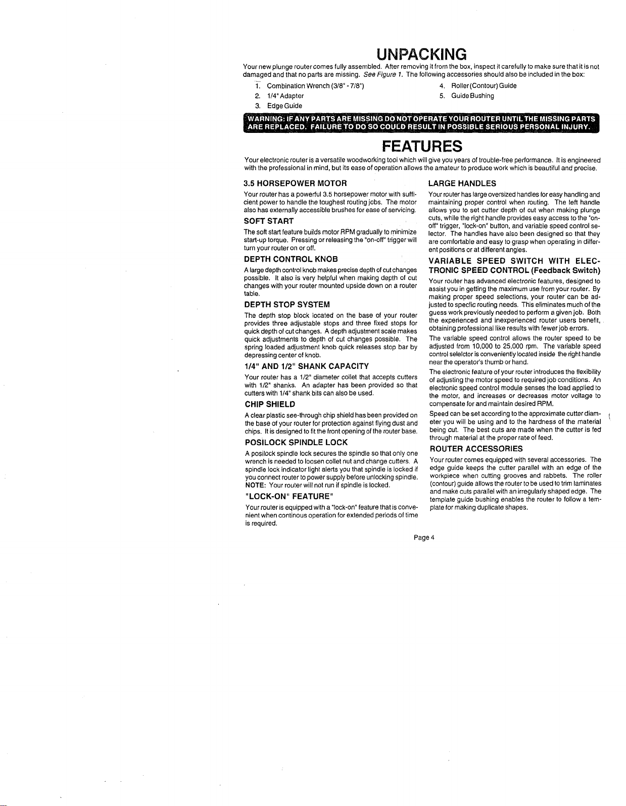
FEATURES
KNOW YOUR ELECTRONIC ROUTER
Before attempting to use your router, familiarize yourself with all operating features and safety requirements. See Figures 1
and2.
DEPTH CONTROL KNOB
LOCK HANDLE
PLUNGE
RELEASE
ACTUATOR
FRONT VIEW OF ROUTER
SPINDLE LOCK
INDICATOR LIGHT
POSILOCK
SPINDLE LOCK
SWITCH HANDLE
VARIABLE SPEED
CONTROLSELECTOR
SCALE
(INCH AND METRIC)
INDICATOR
_16-18
KNOB
ADJUSTMENT KNOB
(DEPRESSING CENTER OF KNOB
QUICK RELEASES STOP BAR)
STOP BAR
STOP SCREW
ADAPTER
COMBINATION WRENCH
(3/8" - 7/8")
DEPTH STOP BLOCK ROTATES
FOR DEPTH OF CUT CHANGES
Page 5
]EX NUT
DEPTH STOP BLOCK
Fig, 1
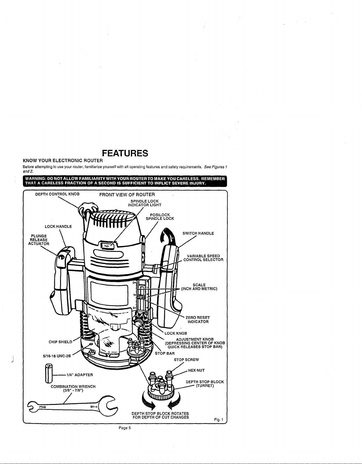
FEATURES
REAR VIEW OF ROUTER
DEPTH CONTROL KNOB
VARIABLE SPEED
CONTROL SELECTOR
POWER CORD
\
"LOCK-ON"
BUTTON
LOCK
HANDLE
"ON-(3
TRIGGER
SWITCH HANDLE
SPEED
SELECTION CHART
5/16-18 UNC-2B
ROUTER
HEX NUT
FLANGE
PLUNGE
ACTUATOR
SUBBASE
COLLET NUT
Fig. 2
ELECTRICAL CONNECTION
Your router has a precision built electric motor. It should be connected to a power supply that is 120 volts, 60 Hz, AC only
(normal household current). Do not operate this tool on direct current (DC). A voltage drop of more than 10 percent will
cause a loss of power and overheating. If your tool does not operate when plugged into an outlet, double-check the power
supply.
The operation of any router can result in foreign objects being thrown into your eyes, which can
result in severe eye damage. Before beginning power tool operation, always wear safety goggles
or safety glasses with side shields and a full face shield when needed. We recommend Wide
Vision Safety Maskfor use over eyeglasses or standard safety glasses with side shields, available
at Sears Retail Stores.
Page 6
ADJUSTMENTS
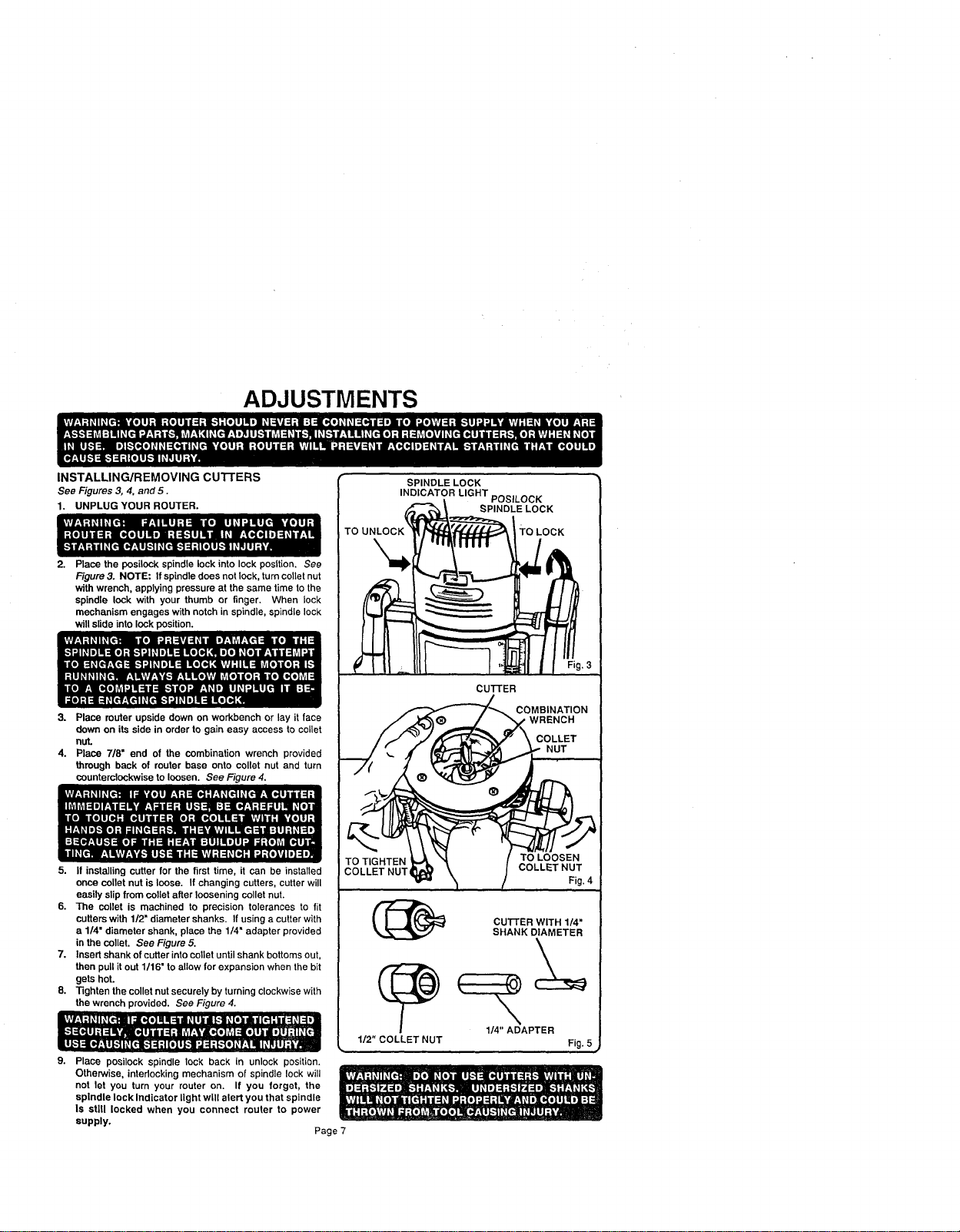
INSTALLING/REMOVING cUTrERS
See Figures 3, 4. and 5.
1. UNPLUG YOUR ROUTER.
Place the posileck spindle lock into lock posttion. See
Figure 3. NOTE: If spindle does not lock, turn caller nut
with wrench, applying pressure at the same time to the
spindle lock with your thumb or finger. When lock
mechanism engages with notch in spindle, spindle lock
will slide into lock position.
3. Place router upside down on workbench or lay it face
down on its side in order togain easy access to collet
nut.
4. Place 7/8= end of the combination wrench provided
through back of router base onto collet nut and turn
counterclockwise to loosen. See Figure 4.
5. If installing cutter for the first time, it can be installed
once ooUetnut is loose. If changing cutters, cutter will
easily slip from oollet after loosening collet nut.
6. The collet is machined to precision tolerances to fit
cutters with 1/2" diameter shanks. If using a cutter with
a 1/4" diameter shank, place the 1/4" adapter provided
in the oollet. See Figure 5.
7. Insert shank of cutter into collet until shank bottoms out,
then pull it out 1/16" to allow for expansion when the bit
gets hot.
8. -righten the collet nut securely by turning clockwise with
the wrench provided. See Figure 4.
9. Place posileck spindle lock back in unlock position.
Otherwise, intedocking mechanism of spindle lock will
not let you turn your router on. If you forget, the
spindle lock Indicator light will alert you that spindle
Is stlU locked when you connect router to power
supply,
Page 7
SPINDLE LOCK
INDICATOR LIGHT POSILOCK
SPINDLE LOCK
TO LOCK
CuI-rER
COMBINATION
WRENCH
COLLET
NUT
TO TIGHTEN
COLLET NUT,
1/2" COLLET NUT
TO LOOSEN
COLLETNUT
Fig. 4
CU'I-rER WITH 1/4"
SHANK DIAMETER
1/4" ADAPTER
Fig. 5
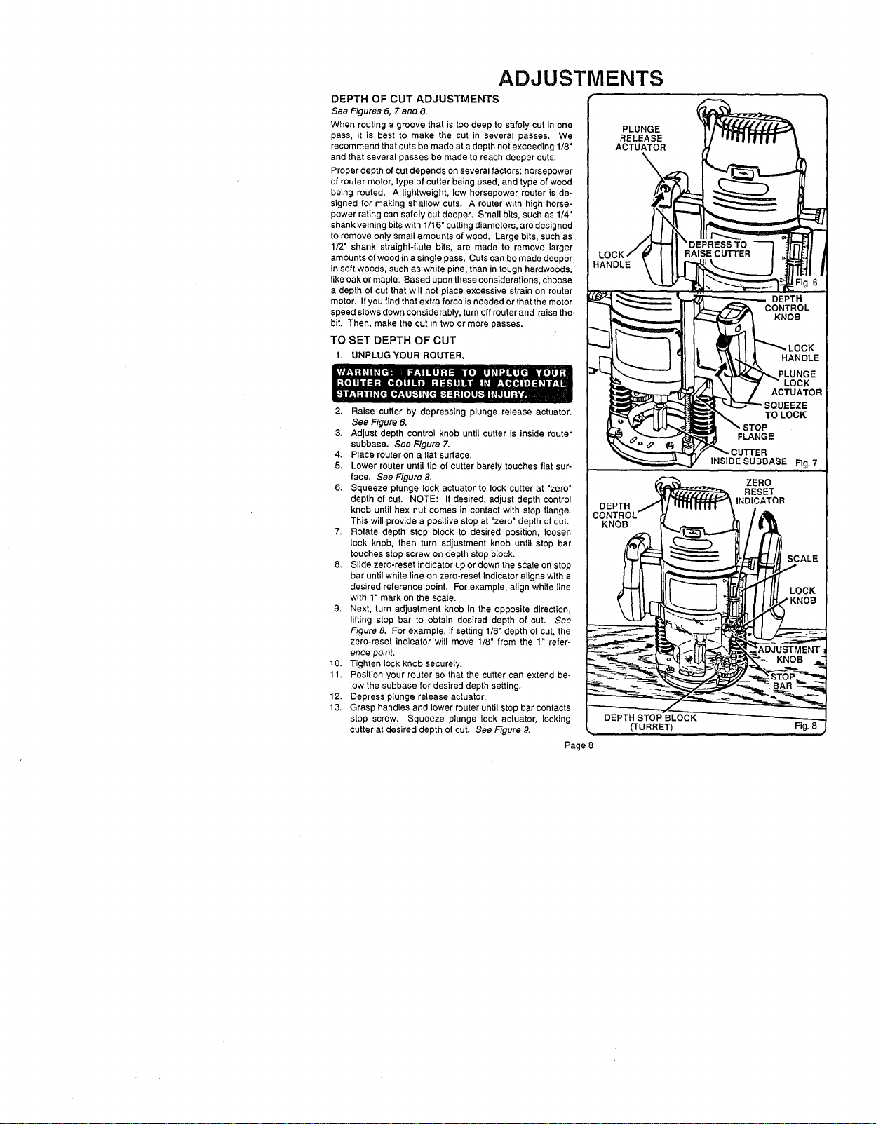
ADJUSTMENTS
DEPTH OF CUT ADJUSTMENTS
See Figures 6, 7 and 8.
When routing a groove that istoo deep to safely cut inone
pass, it is best to make the cut in several passes. We
recommend that cuts bemade at a depth not exceeding 1/8"
and that several passes be made to reach deeper cuts.
Proper depth of cutdepends on several factors: horsepower
of router motor, type of cutter being used, and type of wood
being routed. A lightweight, low horsepower router is de-
signed for making shallow cuts. A router with high horse-
power rating can safely cut deeper. Small bits, such as 1/4"
shank veiningbits with1/16" cuttingdiameters, are designed
to remove only small amounts of wood. Large bits, such as
1/2" shank straight-flute bits, are made to remove larger
amounts ofwood ina single pass, Cuts can be made deeper
in soft woods, such as white pine, than intough hardwoods,
like oak or maple. Based upon these considerations, choose
a depth of cut that will not place excessive strain on router
motor. If you find that extra force is needed or that the motor
speed slows down considerably, turn off router and raise the
bit. Then, make the cut in two or more passes.
TO SET DEPTH OF CUT
1, UNPLUG YOUR ROUTER.
2. Raise cutter by depressing plunge release actuator.
See Figure 6.
3. Adjust depth control knob until cutter is inside router
subbase. See Figure 7.
4. Place router on a flat surface.
5. Lower router until tip of cutter barely touches flat sur-
face. See Figure 8,
6. Squeeze plunge lock actuator to lock cutter at "zero"
depth of cut. NOTE: If desired, adjust depth control
knob until hex nut comes in contact with stop flange.
This will provide a positive stop at "zero" depth of cut.
7. Rotate depth stop block to desired position, loosen
lock knob, then turn adjustment knob until stop bar
touches stop screw on depth stop block.
8. Slide zero-reset indicator up or down the scale on stop
bar until white line on zero-reset indicator aligns with a
desired reference point, For example, align white line
with 1" mark on the scale.
9. Next, turn adjustment knob in the opposite direction,
lifting stop bar to obtain desired depth of cut. See
Figure 8. For example, if setting 1/8" depth of cut, the
zero-reset indicator will move 1/8" from the 1" refer-
ence point.
10. Tighten lock knob securely.
11. Position your router so that the cutter can extend be-
low the subbase for desired depth setting.
12. Depress plunge release actuator.
13, Grasp handles and lower router until stop bar contacts
stop screw. Squeeze plunge lock actuator, locking
cutter at desired depth of cut. See Figure 9.
Page 8
PLUNGE
RELEASE
ACTUATOR
KNOB
(TURRET)
INSIDE SUBBASE
Rg. 7
Fig. 8
ADJUSTMENTS
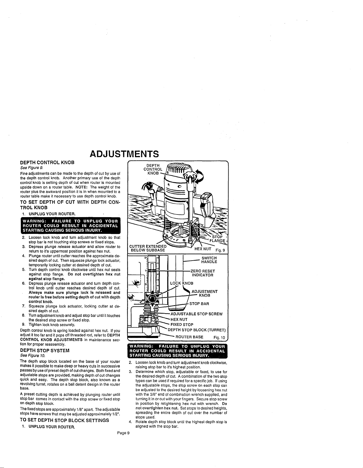
DEPTH CONTROL KNOB
See Figure 9.
Fine adjustments can be made to the depth of cutby use of
the depth control knob. Another primary use of the depth
controlknob is setting depth of cut when router is mounted
upside down on a router table. NOTE: The weight of the
router plus the awkward position it is in when mounted to a
router table make it necessary to use depth control knob.
TO SET DEPTH OF CUT WITH DEPTH CON-
TROL KNOB
1. UNPLUG YOUR ROUTER.
2. Loosen lock knob and turn adjustment knob so that
stop bar is not touching stop screws or fixed stops.
3, Depress plunge release actuator and allow router to
return to it's uppermost position against hex nut.
4. Plunge router until cutter reaches the approximate de-
sired depth of cut. Then squeeze plunge lock actuator,
temporarily locking cutter at desired depth of cut.
5. Turn depth control knob clockwise until hex nut seats
against stop flange. Do not overtlghten hex nut
agalnst stop flange.
6. Depress plunge release actuator and turn depth con-
trol knob until cutter reaches desired depth of cut.
Always make sure plunge lock Is released and
router Is free before setting depth of cut with depth
control knob.
7. Squeeze plunge lock actuator, locking cutter at de-
sired depth of cut.
8, Tum adjustmentknoband adjust stopbar untilittouches
the desired stop screwor fixed stop.
9. Tighten lock knob securely.
Depth controlknob is spring loaded against hex nut. If you
adjust it toofar and it pops offthreaded rod, refer to DEPTH
CONTROL KNOB ADJUSTMENTS in maintenance sec-
tionfor proper reassembly.
DEPTH STOP SYSTEM
See Figure 10.
The depth stop block located on the base of your router
makes it possible to make deep or heavy cutsin successive
passesby usaof presetdepthof cutchanges, Both fixed and
adjustabtestopsare provided, making depth of cutchanges
quick and easy. The depth stop block, also known as a
revolvingturret, rotates on a ball detent design in the router
base.
A preset cuttingdepth is achieved by plunging router until
stop bar comes in contactwith the stop screw or fixed stop
on depth stop block.
The fixed stopsareapproximately 1/8" apart. Theadjustable
stopshave screws thatmay be adjusted approximately 1/2".
TO SET DEPTH STOP BLOCK SETTINGS
1, UNPLUG YOUR ROUTER.
Page 9
DEPTH
CONTROL
KNOB
CUTFER EXTENDED
BELOW SUBBASE HEX NUT Fig. 9
___,__I I I I swrrcR
i_ K O
I_2STOPBAR
I ADJUSTABLE STOPSCREW
I _I_I_K.IF_HEX NUT
-i _'_,..._ _" FIXED STOP
_EPTH STOP BLOCK (TURRET)
_. -- ' _ ROUTER BASE Fig. 10
2. Loosen lock knob and turn adjustment knob clockwise,
raising stop bar to it's highest position.
3. Determine which stop, adjustable or fixed, to use for
the desired depth of cut. A combination of the two stop
types can be used ifrequired for a specific job. If using
the adjustable steps, the stop screw on each stop can
be adjusted to the desired height by loosening hex nut
with the 3/8" end of combination wrench supplied, and
turning it in or out with your fingers. Secure stop screw
in position by retightening hex nut with wrench, Do
not overtlghten hex nut. Set stops to desired heights,
spreading the entire depth of cut over the number of
stops used.
4. Rotate depth stop block until the highest depth stop is
aligned with the stop bar.
ADJUSTMENTS
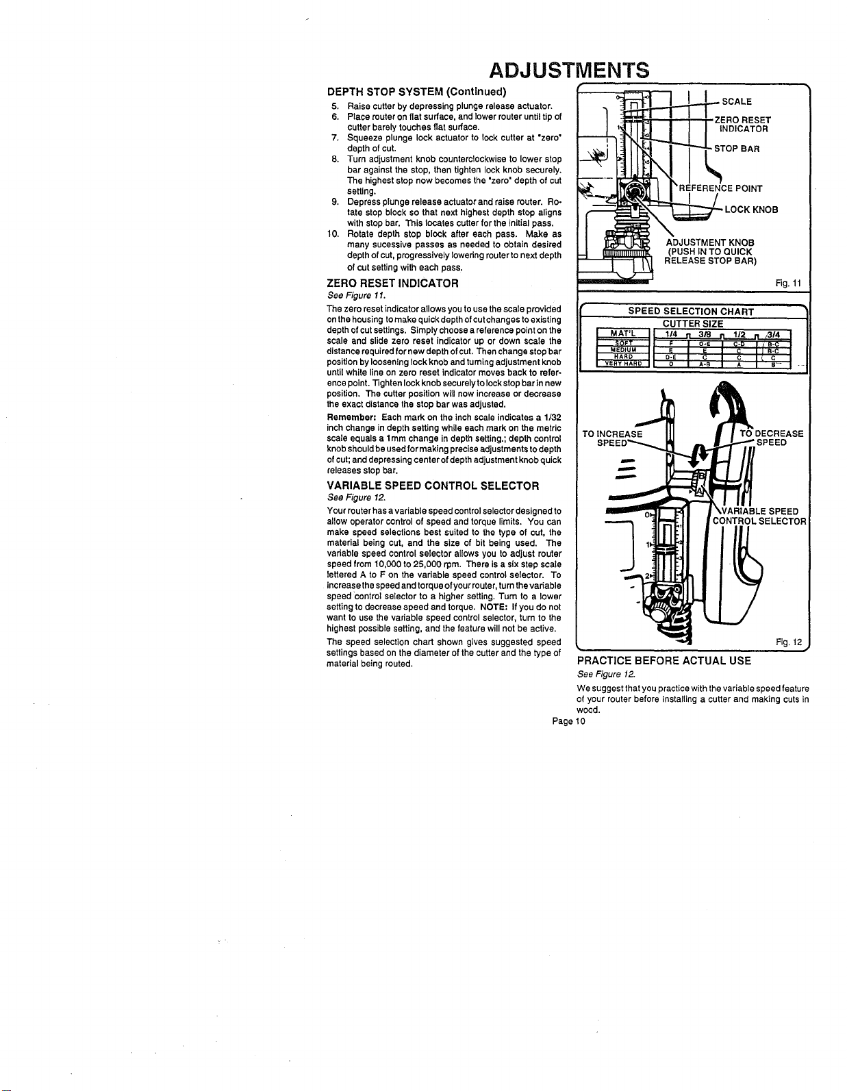
DEPTH STOP SYSTEM (Continued)
5. Raise cutter by depressing plunge release actuator.
6. Place routeron fiatsurface, and _ower routerunti_tip of
cutter barely touches flat surface.
7. Squeeze plunge lock actuator to lockcutter at "zero"
depth of cut.
8. Turn adjustment knob counterclockwise to lower stop
bar againstthe stop, then tighten lock knob securely.
The higheststop now becomes the "zero" depth of cut
setting.
9. Depress plunge release actuator and raise router. Ro-
tate stop block so that next highest depth stop aligns
with stop bar. This locates cutter for the initial pass,
10, Rotate depth stop block after each pass. Make as
many suceSsive passes as needed to obtain desired
depth ofcut, progressively Iowedng routerto next depth
of cutsetting with each pass.
ZERO RESET INDICATOR
See Figure 11.
The zero reset indicatorallows you to use the scale provided
onthe housing tomake quick depth of cutchanges to existing
depth of cutsettings. Simply choose a reference point on the
scale and slide zero reset indicator up or down scale the
distancerequired for new depth ofcut. Then change stop bar
positionby looseninglock knob and tumtngadjustment knob
until white line on zero reset indicator moves back to refer-
ence point.13ghtenlockknob securelytolock stop barinnew
position. The cutter positionwill now increase or decrease
the exact distancethe stop bar was adjusted.
Remember: Each mark on the inch scale indicates a 1/32
inch change in depth setting while each mark on the metric
scale equals a 1ram change in depth setting.;depth control
knob shouldbeusedfor makingpreciseadjustments todepth
ofcut;and depressingcenter ofdepth adjustment knobquick
releases stop bar.
VARIABLE SPEED CONTROL SELECTOR
See Figure 12.
Your muter has avariable speed controlselectordesigned to
allow operator control of speed and torque limits. You can
make speed selections best suited to the type of cut, the
material being cut, and the size of bit being used. The
variable speed control selector allows you to adjust muter
speed from 10,000 to 25,000 rpm. There is a six step scale
lettered A to F on the variable speed control selector. To
increase thespeed and torqueof yourrouter,turnthe variable
speed control selector to a higher setting. Turn to a lower
setting to decrease speed and torque. NOTE: If you do not
want to use thevariable speed controlselector, turn to the
highest possiblesetting, and the feature will not be active.
The speed selection chart shown gives suggested speed
settingsbased on the diameter of the cutter and the type of
material being routed.
._._ SCALE
'_REFERENCE POINT
LOCK KNOB
ADJUSTMENT KNOB
Fig. 11
SPEED SELECTION CHART
CUTTER SIZE
I "'MAT'L_IL 114 rl 3/'8 n 1/2
t _SOF'r :1[ F I _-e J C-_ "lJ--'_:E_-_
MEDIUM t L E I E I C I J B-C I
I HARD I D-E C I C I C I
VeRY HARD I |, D A-B A I s- I -
TOINCREASE TO DECREASE
WARIABLESPEED
CONTROLSELECTOR
Fig, 12
PRACTICE BEFORE ACTUAL USE
See Figure 12.
We suggest that you practice with the variable speed feature
of your router before installing a cutter and making cuts in
wood.
Page 10
OPERATION
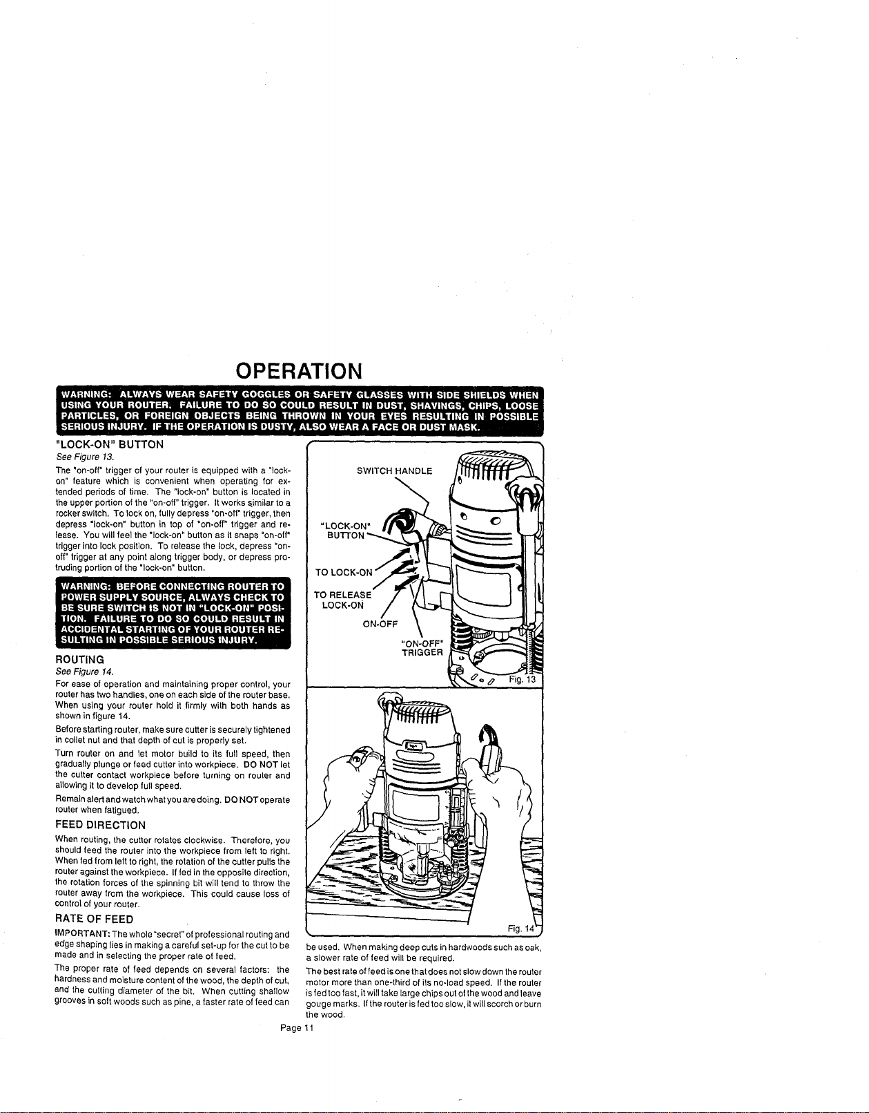
"LOCK-ON" BUTTON
See Figure 13.
The "on-off" trigger of your router is equipped with a "lock-
on" feature which is convenient when operating for ex-
tended periods of time. The "lock-on" button is located in
the upper portion of the "on-off" trigger. It works similar to a
rocker switch. To lock on, fully depress "on-off" trigger, then
depress "lock-on" button in top of "on-off" trigger and re-
lease. You will feel the "lock-on" button as it snaps "on-off"
trigger into lock position. To release the lock, depress =on-
off" trigger at any point along trigger body, or depress pro-
truding portion of the "lock-on" button.
ROUTING
See Figure 14.
For ease of operation and maintaining proper control, your
router has two handles, one on each side of the router base.
When using your router hold it firmly with both hands as
shown in figure 14.
Before starting router, make sure cutter is securely tightened
in collet nut and that depth of cut is properly set.
Turn router on and let motor build to its full speed, then
gradually plunge or feed cutter into workpiece. DO NOT let
the cutter contact workpiece before turning on router and
allowing it to develop full speed,
Remain alert and watch what you are doing. DO NOT operate
router when fatigued.
FEED DIRECTION
When routing, the cutter rotates clockwise. Therefore, you
should feed the router into the workpiece from left to right.
When fed from left to right, the rotation of the cutter pulls the
router against the workpiece. If fed in the opposite direction,
the rotation forces of the spinning bit will tend to throw the
router away from the workpiece. This could cause loss of
control of your router.
RATE OF FEED
IMPORTANT: The whole "secret" of professional routing and
edge shaping lies in making a careful set-up for the cut to be
made and in selecting the proper rate of feed.
The proper rate of feed depends on several factors: the
hardness and moisture content of the wood, the depth of cut,
and the cutting diameter of the bit. When cutting shallow
grooves in soft woods such as pine, a faster rate of feed can
be used. When making deep cuts in hardwoods such as oak,
a slower rate of feed will be required.
The best rate of feed is one that does not slow down the router
motor more than one-third of its noqoad speed. If the router
is fed too fast, it will take large chips out of the wood and leave
gouge marks. If the router is fed too slow, it will scorch or burn
the wood.
SWITCH HANDLE
TO
TO RELEASE
LOCK-ON
ON-OFF
Fig. 1
Page 11
OPERATION
PROPER FEEDING
The rightfeed is neither too fast nortoo slow. It isthe rate at
whichthe bit is being advanced firmly and surely to produce
a continuous spiral of uniformchips -- without hogging into
thewood tomake large individualchips or,on theotherhand,
to create only sawdust. If you are making a small diameter,
shallow groove in soft, dry wood, the proper feed may be
about as fast as you can travel yourrouter along your guide
line. On theother hand,if thebit isa large one, thecut is deep
orthewood ishard tocut, theproperfeed may be avery slow
one. Then, again, a cross-grain cut may require a slower
pace than an identical withgrain cut in thesame workpiece.
There is no fixed rule. You will learn by experience from
practice and use. The best rate of feed is determined by
listening to the sound of the router motorand by feeling the
progress of each cut. If at all possible, always test a cut on
a scrap piece of the workpiece wood, beforehand.
SPEED SELECTION
In general, if the material being cutis hard, the cutter size is
large, orthe depth of cutis deep (maximum 1/8"), then your
routershouldbe runat slowerspeeds. When these si!uations
exist,turnthe variable speed controlselector untilthe desired
speed is reached. NOTE: Carbide cutters cut at higher
speeds than steel cutters and should be used when cutting
very hard materials.
FORCE FEEDING
Clean, smooth routing and edge shaping can be done only
when the bit is revolving at a relatively high speed and is
takingvery small bites toproduce tiny,cleanly severed chips.
If your router is forced to move forward too fast, the RPM of
the bit becomes slower than normalin relation toits forward
movement. As a result, the bit must take bigger bites as it
revolves. "Bigger bites"mean bigger chips, and a rougher
finish. Bigger chips also require more power, which could
result in the router motor becoming overloaded.
Under extreme force-feeding conditionsthe relativeRPM of
the bitcan become soslow -- and the bites it has to take so
large -- that chips will be partially knocked off (rather than
fully cut off), with resulting splintering and gouging of the
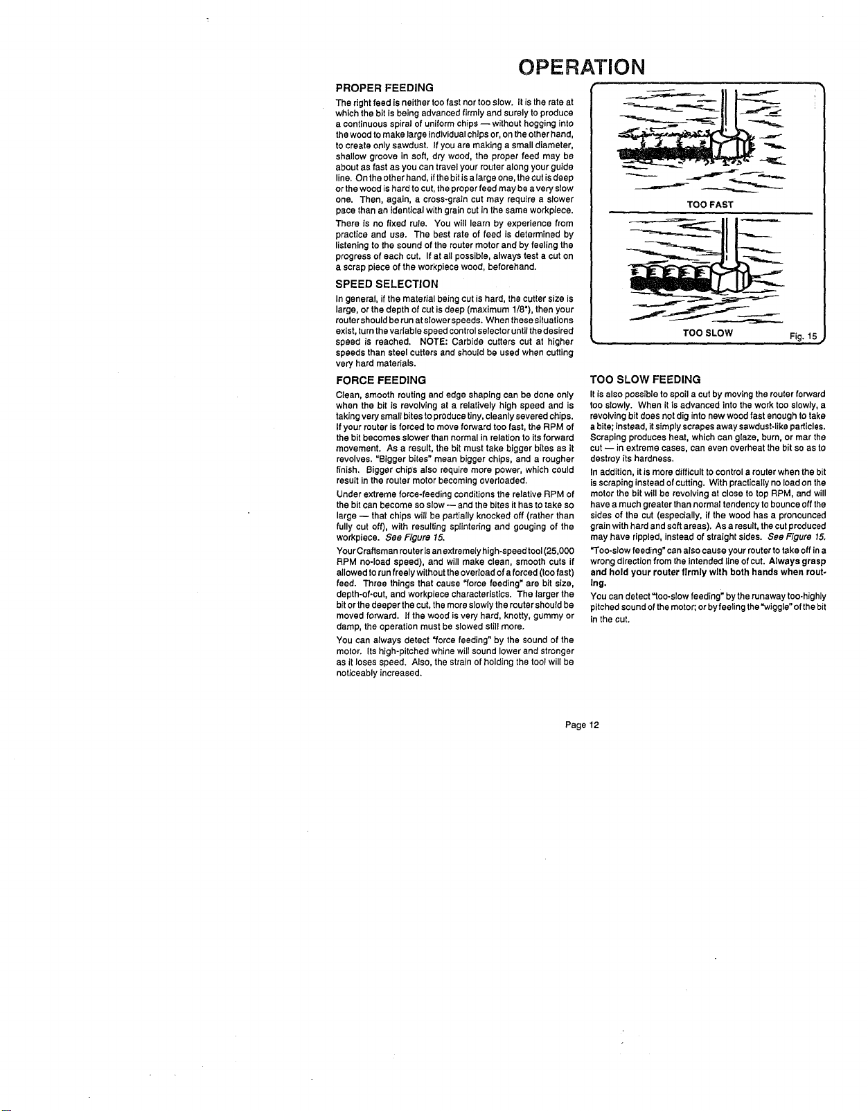
workpiece. See Figure 15.
Your Craftsman router isanextremely high-speed tool(25,000
RPM no-load speed), and will make clean, smooth cuts if
allowed torun freely withouttheoverloadof aforced (toofast)
feed. Three things that cause "force feeding" are bit size,
depth-of-cut, and workpiece characteristics. The larger the
bitor the deeper the cut, themore slowlythe routershouldbe
moved forward. If the wood isvery hard, knotty, gummy or
damp, the operation must be slowed stillmore,
You can always detect "force feeding" by the sound of the
motor. Its high-pitched whine will sound lower and stronger
as it loses speed. Also, the strain of holding the tool will be
noticeably increased.
TOO FAST
TOO SLOW
Fig. 15
TOO SLOW FEEDING
It is alsopossible to spoila cut bymoving therouter forward
too slowly. When it is advanced intothe work tooslowly, a
revolvingbit doesnot diginto new wood fast enough to take
abite; instead, it simplyscrapes away sawdust-likeparticles.
Scraping produces heat, whichcan glaze, bum, or mar the
cut -- in extreme cases, can even overheat the bit so as to
destroy itshardness,
In addition, it is more difficultto control a router when the bit
isscrapinginsteadof cutting. With practicallyno loadon the
motorthe bit will be revolving at close to top RPM, and will
have a much greater than normaltendency to bounceoffthe
sides of the cut (especially, if the wood has a pronounced
grain with hard and soft areas), Asa result, thecutproduced
may have rippled, instead of straight sides. See Figure 15.
"Too-slow feeding" can also cause your router to take off ina
wrongdirectionfrom theintended lineof cut. Always grasp
and hold your router firmly with both hands when rout-
Ing.
You can detect "too-slow feeding" by therunaway too-highly
pitchedsound of themotor;orbyfeeling the"wiggle" of thebit
in the cut.
Page12
OPERATION
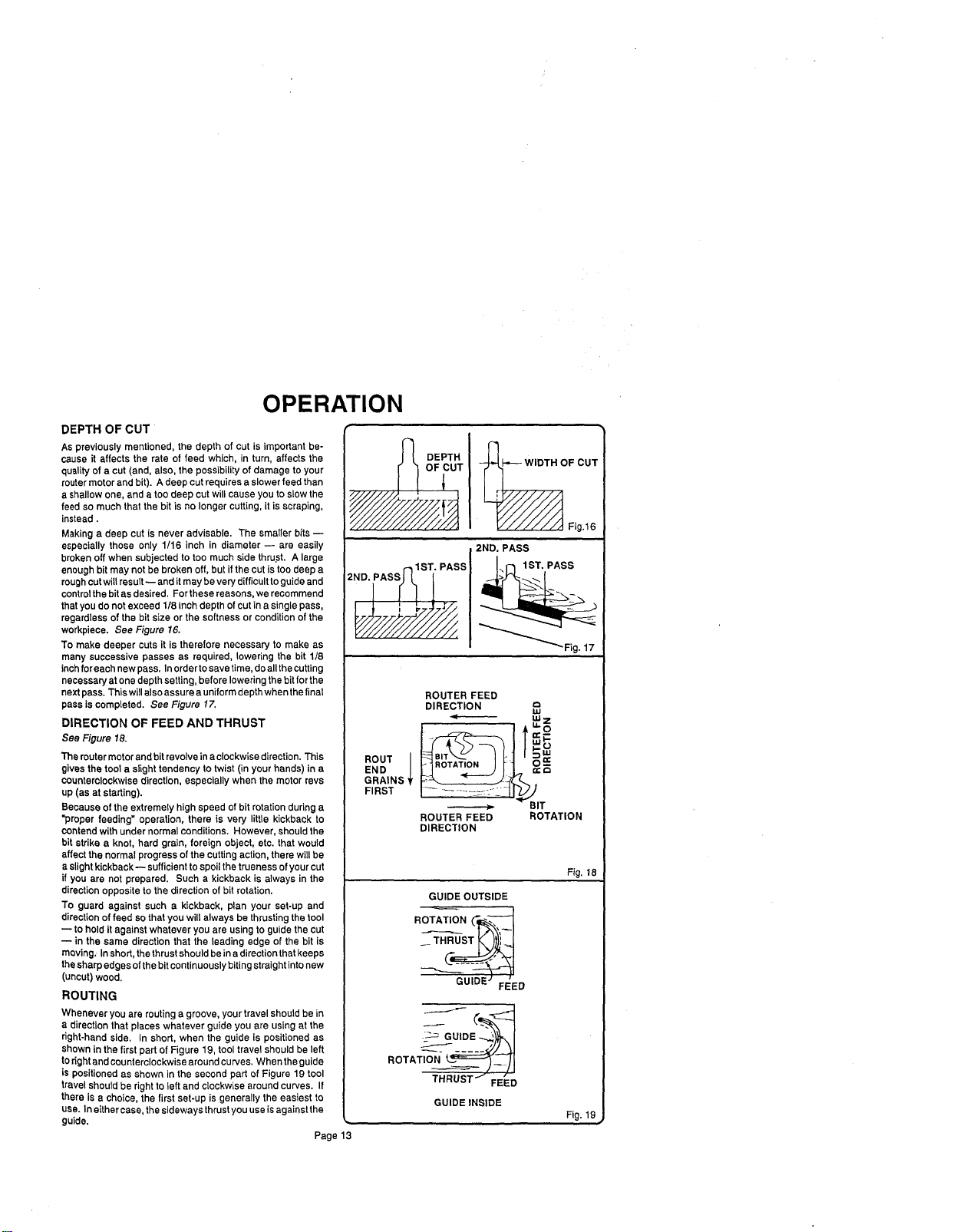
DEPTH OF CUT
As previously mentioned, the depth of cut isimportant be-
cause it affects the rate of feed which, in turn, affects the
qualityof a cut (and, also, the possibilityof damage to your
router motor and bit). A deep cutrequires a slowerfeed than
a shallowone, and a too deep cut willcause you toslow the
feed somuch that the bit is no longer cutting, it is scraping,
instead.
Making a deep cut is never advisable. The smaller bits--
especially those only 1/16 inch in diameter -- are easily
broken off when subjected to too much side thrust. A large
enough bitmay not be broken off, but if thecut is too deep a
roughcutwillresult-- and it may be verydifficulttoguideand
controlthebitas desired, For these reasons,we recommend
that you do not exceed 1/8 inch depthof cut in a single pass,
regardless of the bit size or the softness or conditionof the
workpiece. See Figure 16.
To make deeper cuts it is therefore necessary to make as
many successive passes as required, lowering the bit 1/8
inchfor each newpass. Inorderto savetime,do allthe cutting
necessaryat one depth setting,before loweringthe bitfor the
nextpass. Thiswill alsoassure a uniformdepthwhenthe final
pass is completed, See Figure 17.
DIRECTION OF FEED AND THRUST
See Figure 18.
The routermotorand bit revolvein a clockwisedirection. This
gives the toola slight tendency to twist (in your hands) in a
counterclockwisedirection, especially when the motorrevs
up (as at starting).
Because of the extremely high speed of bit rotationduring a
"proper feeding" operation, there is very little kickback to
contendwith under normalconditions. However, shouldthe
bit strike a knot, hard grain, foreign object, etc. that would
affect the normal progress of thecutting action,there will be
a slightkickback-- sufficientto spoilthe truenessof yourcut
if you are not prepared. Such a kickback is always in the
directionopposite to the direction of bit rotation,
To guard against such a kickback, plan your set-up and
directionof feed so thatyou will always be thrustingthe tool
to hold itagainst whatever you are usingto guidethe cut
-- in the same direction that the leading edge of the bit is
moving. Inshort, thethrustshould beina directionthatkeeps
thesharpedges ofthebitcontinuouslybiting straightintonew
(uncut) wood.
ROUTING
Whenever you are routing a groove, yourtravel should be in
a direction that places whatever guide you are using at the
dght-hand side. In short, when the guide is positioned as
shown in the first part of Figure 19, tool travel should be left
toright and counterclockwise around curyes. When the guide
is positioned as shown in the second part of Figure 19 tool
travelshould be right to left and c{ockwise around curves. If
there is a choice, the first set-up is generally the easiest to
usa. In eithercase. the sideways thrust you use isagainst the
guide.
Page 13
DEPTH _OF CUT
_UT V/////A,,I Fig,16
2ND. PASS
°
ROUTER FEED
DIRECTION "
I.U
I /T
ROUT I H.B_tA_'_TJUO.] __ | o==-
END __
GRAINS
FIRST
_ BIT
ROUTER FEED ROTATION
DIRECTION
GUIDE OUTSIDE
GUIDE FEED
ROTA__
THRUST'J_=_
FEED
GUIDEINSIDE
Fig. 18
Fig. 19
OPERATION
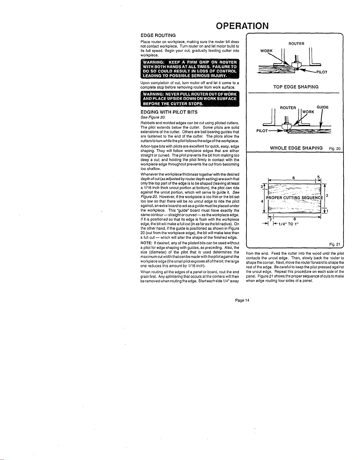
EDGE ROUTING
Place router on workplace, making sure the router bit does
not contact workpieea. Turn router on and let motor build to
its full speed. Begin your cut, gradually feeding cutter into
workpiece.
Upon completion of cut, turn motor off and let it come to a
complete stop before removing router from work surface.
EDGING WITH PILOT BITS
See Figure 20.
Rabbets and molded edges can be cut using piloted cutters.
The pilot extends below the cutter. Some pilots are solid
extensions of the cutter. Others are ball bearing guides that
are fastened to the and of the cutter. The pilots allow the
cutters toturn while the pilotfollows the edge ofthe workpiece.
Arbor-type bits with pilots are excellent for quick, easy,,edge
shaping. They will follow workpieca edges that are either
straight or curved. The pilot prevents the bit from making too
deep a cut; and holding the pilot firmly in contact with the
workpiece edge throughout prevents the cut from becoming
too shallow.
Whenever theworkpieca thickness together with the desired
depth ofcut (as adjusted by router depth setting) aresuch that
only the top part of the edge is to be shaped (leaving at least
a 1/16 inch thick uncut portion at bottom), the pilot can ride
against the uncut portion, which will serve to guide it. See
Figure 20. However, ifthe workplace is too thin or the bit set
too low so that there will be no uncut edge to ride the pilot
against, an extra board to actas a guide mustbe placed under
the workpiece. This "guide" board must have exactly the
same contour--straight or curved--as theworkpieea edge.
If it is positioned so that its edge is flush with the workpieee
edge, the bit will make a full cut (in as far as the bit radius). On
the other hand, if the guide is positioned as shown in Figure
20 (out from the workpieee edge), the bit will make less than
a full cut -- which will alter the shape of the finished edge.
NOTE: If desired, any of the piloted bits can be used without
a pilot for edge shaping with guides, as preceding. Also, the
size (diameter) of the pilot that is used determines the
maximum cut width that can be made with thepilot against the
workpiece edge (the small pilot exposes all ofthe bit; the large
one reduces this amount by 1/16 inch).
When routing aII the edges of a panel or board, rout the end
grain first. Any splintering that occurs at the corners will then
be removed when routing the edge. Start eachside 1/4" away
ROUTER
_LOT
TOP EDGE SHAPING
WHOLE EDGE SHAPING Fig,20
I" 6 I_
_ _-1/4"TO1"
Fig. 21
#
from the end. Feed the cutter into the wood until the pilot
contacts the uncut edge. Then, slowly back the router to
shape thecorner. Next, move the router forward to shape the
rest ofthe edge. Be careful to keep the pilot pressed against
the uncut edge. Repeat this procedure on each side of the
panel. Figure 21shows the proper sequence of cuts tomake
when edge routing four sides of a panel.
Page 14
OPERATION
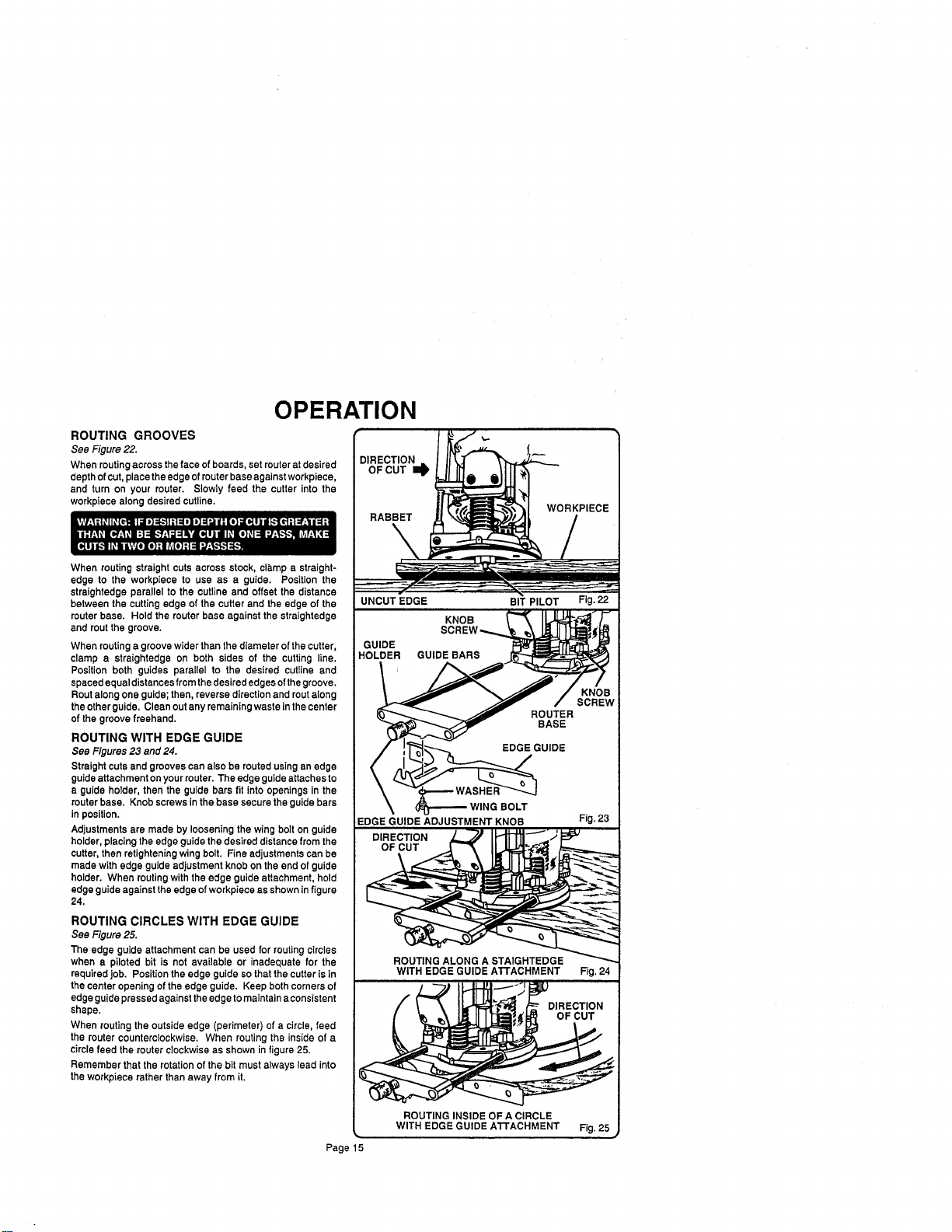
ROUTING GROOVES
See Figure 22.
When routingacross the face of boards, set router atdesired
depthof cut, placethe edge ofrouter base againstworkpiece,
and turn on your router. Slowly feed the cutter into the
workpiece along desired cutline.
When routing straight cuts across stock, cla,mp a straight-
edge to the workpiece to use as a guide. Position the
straightedge parallel to the cutline and offset the distance
between the cutting edge of the cutter and the edge of the
router base. Hold the router base against the straightedge
and rout the groove,
When routinga groovewider than the diameter of the cutter,
clamp a straightedge on both sides of the cutting line.
Position both guides parallel to the desired cutline and
spaced equal distances from thedesirededges ofthegroove.
Routalong one guide;then, reverse directionand routalong
the otherguide, Clean outany remaining waste inthe center
of thegroove freehand.
ROUTING WITH EDGE GUIDE
See Figures 23 and 24.
Straight cutsand grooves can also be routed usingan edge
guideattachment onyour router.The edge guide attaches to
a guide holder, then the guide bars fit intoopenings in the
routerbase. Knob screws inthe base securethe guide bars
in position.
Adjustments are made by loosening the wing bolt on guide
holder, placingthe edge guidethe desired distancefrom the
cutter, then retighteningwing bolt. Fine adjustments can be
made with edge guide adjustment knob onthe end of guide
holder. When routingwith the edge guide attachment, hold
edge guideagainst theedge of workpiece as shownin figure
24.
ROUTING CIRCLES WITH EDGE GUIDE
See Figure 25.
The edge guide attachment can be used for routingcircles
when a piloted bit is not available or inadequate for the
requiredJob. Position theedge guide sothat thecutter is in
the center opening of theedge guide. Keep both cornersof
edge guidepressedagainst theedge tomaintain aconsistent
shape.
When routing the outside edge (perimeter) of a circle, feed
the router counterclockwise. When routing the inside of a
circle feed the routerclockwise as shown in figure 25.
Remember that the rotationofthe bit must always lead into
the workpiece rather than away from it,
DIRECTION
OF CUT I_
RABBET
UNCUT EDGE BIT PILOT Fig. 22
KNO llJ " E
HOLDER GUIDE BAR_
/ ',"[_ _--_.._., EDGEGUIDE
- /
EDGE GUIDE ADJUSTMENT KNOB Fig. 23
DIRECTION ] _J IH-_I "''''_.
OF CUT _._
O _ _ _
ROUTING ALONG A STAIGHTEDGE _
WITH EDGE GUIDE AI"rACHMENT Fig. 24
DIRECTION
OF CUT
ROUTING INSIDE OF A CIRCLE
_. WITH EDGE GUIDE ATTACHMENT Fig. 25 ,_
Page 15
OPERATION
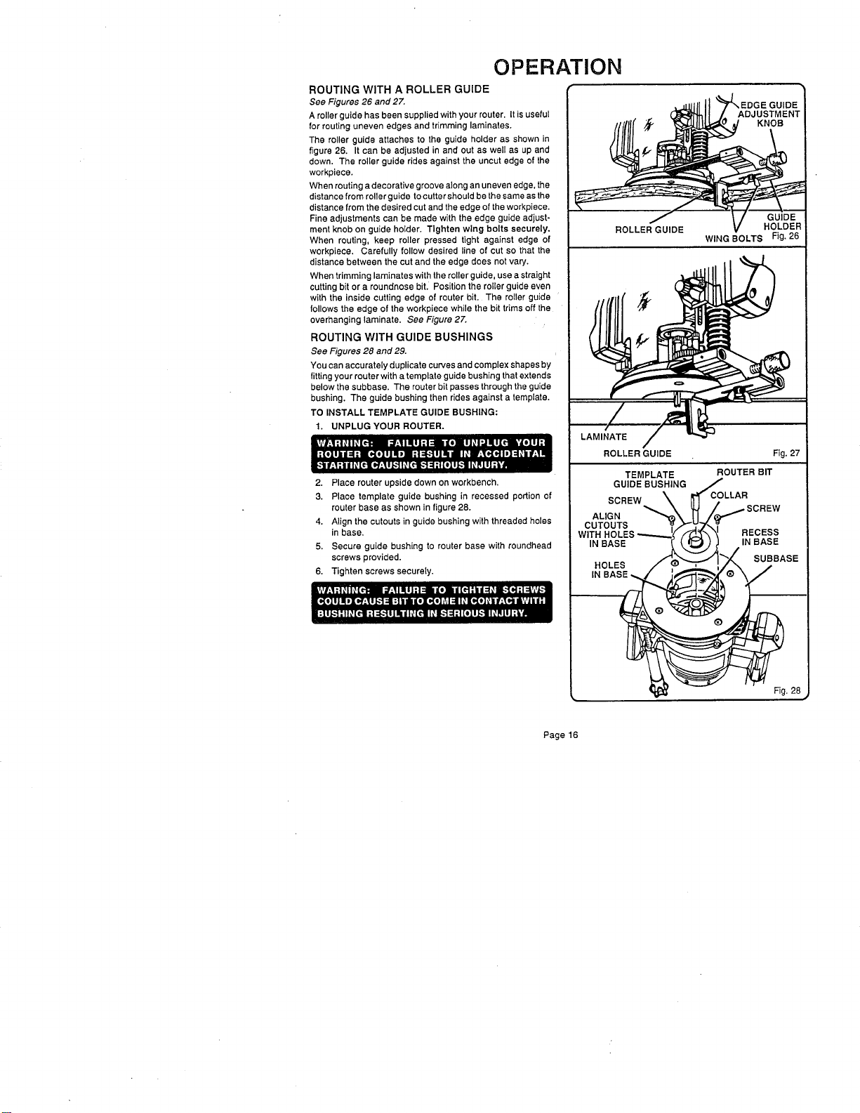
ROUTING WITH A ROLLER GUIDE
See Figures 26 and 27.
Aroller guide has been supplied with your router, It is useful
for routing uneven edges and trimming laminates,
The roller guide attaches to the guide holder as shown in
figure 26, It can be adjusted in and out as well as up and
down. The roller guide rides against the uncut edge of the
workpiece.
When routing a decorative groove along an uneven edge, the
distance from roller guide to cutter should be the same as the
distance from the desired cut and the edge of the workpiece.
Fine adjustments can be made with the edge guide adjust-
ment knob on guide holder. Tighten wing bolts securely.
When routing, keep roller pressed tight against edge of
workpiece, Carefully follow desired line of cut so that the
distance between the cut and the edge does not vary.
When trimming laminates with the roller guide, use a straight
cutting bit or a roundnose bit, Position the roller guide even
with the inside cutting edge of router bit, The roller guide
follows the edge of the workpiece while the bit trims off the
overhanging laminate. See Figure 27.
ROUTING WITH GUIDE BUSHINGS
See Figures 28 and 29.
You can accurately duplicate curves and complex shapes by
fitting your router with a template guide bushing that extends
below the subbase. The router bit passes through the guide
bushing. The guide bushing then rides against a template.
TO INSTALL TEMPLATE GUIDE BUSHING:
1. UNPLUG YOUR ROUTER.
2. Place router upside down on workbench,
3. Place template guide bushing in recessed portion of
router base as shown in figure 28.
4. Align the cutouts in guide bushing with threaded holes
in base,
5, Secure guide bushing to router base with roundhead
screws provided.
6. Tighten screws securely.
I
/I //fff _ _:l_J! _(_ _] KNOB
/ V GU,DE
ROLLER GUIDE HOLDER
WING BOLTS Fig. 26
LAMINATE
ROLLER GUIDE Fig. 27
ALIGN
CUTOUTS
WITH F
IN
Page 16
OPERATION
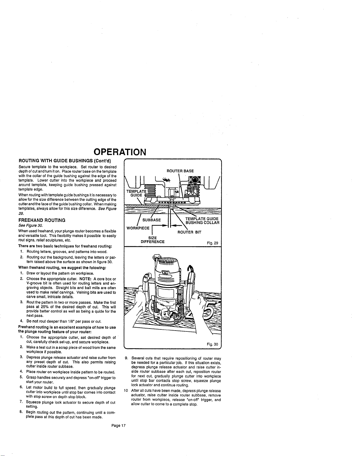
ROUTING WITH GUIDE BUSHINGS (Cont'd)
Secure template to the workpiece. Set router to desired
depth of cutand turn it on. Place routerbase onthetemplate
withthe collar of the guide bushing against the edge of the
template. Lower cutter into the workpiece and proceed
around template, keeping guide bushing pressed against
template edge,
When routingwithtemplate guidebushings itisnecessaryto
allowfor the size difference between the cuttingedge of the
cutterand theface of theguidebushing collar, When making
templates, always allow forthis size difference. See Figure
29.
FREEHAND ROUTING
See Figure 30.
When used freehand, your plunge muter becomes a flexible
and versatiletool. This flexibility makes it possible to easily
routsigns, relief sculptures, etc.
There are two basic techniques for freehand routing:
t. Routing letters, grooves, and patterns intowood.
2. Routing out the background, leaving the letters orpat-
tern raised above the surface as shown in figure 30.
When freehand routing, we suggest the folowlng:
1. Draw orlayout the pattern on workpiece.
2. Choose the appropriate Cutter. NOTE: A core box or
V-groove bit is often used for routing letters and en-
graving objects. Straight bits and ball mills are often
used to make relief carvings, Veining bits are used to
carve small, intricate details.
3. Rout the pattern in two ormore passes. Make the first
pass at 25% of the desired depth of cut. This will
provide better control as well as being a quidefor the
next pass.
4. Do not rout deeper than 1/8" per pass or cut,
Freehand routing Is an excellent example of how to use
the plunge routing feature of your router:
1. Choose the appropriate cutter, set desired depth of
cut, carefully check set-up, and secure workpiece.
2. Make a test cut in a scrap piece of wood from the same
workpiece if possible.
3. Depress plunge release actuator and raise cutter from
any preset depth of cut. This also permits raising
cutter inside router subbsse.
4. Place router on workpiece inside pattern to be routed.
5. Grasp handles securely and depress "on-off" trigger to
startyour router.
6. Let motor build to full speed, then gradually plunge
cutter into workpiece until stop bar comes into contact
with stop screw on depth stop block.
7. Squeeze plunge lock actuator to secure depth of cut
setting.
8. Begin routing out the pattern, continuing until a com-
pletepass at this depth of cuthas been made,
ROUTER BASE
WORKPIECE
SIZE
DIFFERENCE
ROUTER BIT
Fig. 29
9. Several cuts that require repositioningof muter may
be needed for a particular job. If this situation exists,
depress plunge release actuator and raise cutter in-
side router subbase after each cut, reposition router
for next cut, gradually plunge cutter into workpiece
until stop bar contacts stop screw, squeeze plunge
lock actuator and continue routing.
10 After all cuts have been made, depress plunge release
actuator, raise cutter inside router subbase, remove
router from workpiece, release "on-oft" trigger, and
allow cutter to come to a complete stop.
Page17
MAINTENANCE
GENERAL
Only the parts shown on parts list, page 23, are intended to
be repaired or replaced by the customer. All other parts
represent an important part of the double insulation system
and should be serviced only by a qualified Sears service
technician.
Avoid using solvents when cleaning plastic parts. Most
plastics are susceptible to various types of commercial
solvents and may be damaged by their use. Use clean
cloths to remove dirt, carbon dust, etc.
When electric tools are used on fiberglass boats, sports
cars, wallboard, spackling compounds, or plaster, it has
been found that they are subject to accelerated wear and
possible premature failure, as the fiberglass chips and
grindings are highly abrasive to bearings, brushes,
commutator, etc. Consequently, it is not recommended that
this tool be used for extended work on any fiberglass material,
wallboard, spackling compounds, or plaster. During any
use on fiberglass it is extremely important that the tool is
cleaned frequently by blowing with an air jet.
PROPER CARE OF CUTTERS
Get faster more accurate cuttingresults by keeping cutters
clean and sharp.Remove all accumulated pitchand gum from
cutters after each use,
When sharpening cutters, sharpen only the inside of the
cuttingedge. Never grindtheoutsidediameter, Be surewhen
sharpening theend ofa cutterto grind theclearance angle the
same as originally ground,
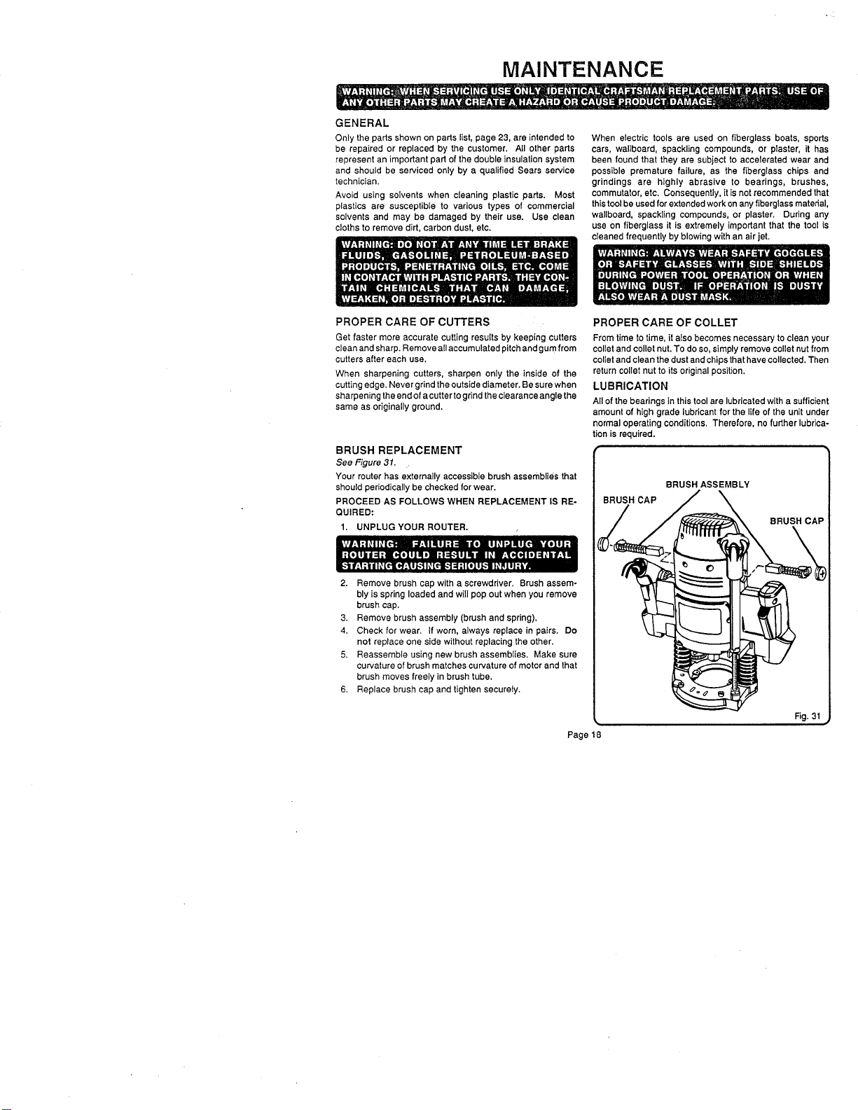
BRUSH REPLACEMENT
See Figure 31.
Your router has externally accessible brush assemblies that
should periodicallybe checked forwear.
PROCEED AS FOLLOWS WHEN REPLACEMENT IS RE-
QUIRED:
1. UNPLUG YOUR ROUTER.
2. Remove brush cap with a screwdriver. Brush assem-
bly is spring loaded and will pop out when you remove
brush cap.
3. Remove brush assembly (brush and spring).
4. Check for wear. If worn, always replace in pairs. Do
not replace one side without replacing the other.
5. Reassemble using new brush assemblies. Make sure
curvature of brush matches curvature of motor and that
brush moves freely in brush tube.
6. Replace brush cap and tighten securely.
Page18
PROPER CARE OF COLLET
From time to time, it also becomes necessary to clean your
collet and collet nut.To do so, simplyremove collet nut from
toilet and clean the dustand chips that have collected. Then
return collet nut to its original position.
LUBRICATION
All of the bearings in this tool are lubricated with a sufficient
amount of high grade lubricant for the life of the unit under
normal operating conditions. Therefore, no further lubrica-
tion is required.
BRUSH ASSEMBLY
BRUSH CAP
BRUSH CAP
Rg. 31
MAINTENANCE
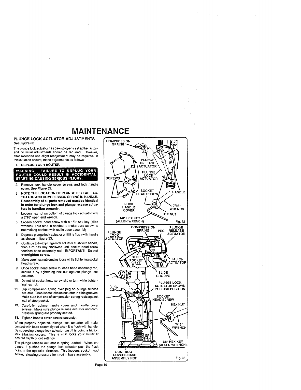
PLUNGE LOCK ACTUATOR ADJUSTMENTS
See Figure 32.
The plunge lock actuator has been properly set at the factory
and no initial adjustments should be required. However,
after extended use slight readjustment may be required. If
this situation occurs, make adjustments as follows:
1. UNPLUG YOUR ROUTER.
2. Remove lock handle cover screws and lock handle
cover. See Figure 32.
3. NOTE THE LOCATION OF PLUNGE RELEASE AC-
TUATOR AND COMPRESSION SPRING IN HANDLE.
Reassembly of all parts removed must be Identical
In order for plunge lock and plunge release actua-
tors to function properly.
4. Loosen hex nut on bottomof plunge lockactuator with
a 7/16" open end wrench.
5. Loosen socket head screw with a 1/8" hex key (allen
wrench). This step is needed to make sure screw is
not making contact with red in base assembly.
6. Depress plunge lockactuatoruntil itis flushwithhandle
as shown infigure 33.
7, Continueto hold plunge lock actuator flushwith handle,
then turn hex key clockwise until socket head screw
touches base assembly rod. IMPORTANT: Do not
overtlghten screw.
8, Make sure hex nut remainsloose whiletighteningsocket
head screw,
9. Once socket head screw touches base assembly rod,
secure it by tightening hex nut against plunge lock
actuator.
10, Do not let socket head screw slipor turn while tighten-
ing hex nut.
11. Slip compression spring over peg on plunge release
actuator. Then locate tabson actuator inslide grooves.
Make sure thatend ofcompression spring restsagainst
wall of stop pocket.
12. Carefully replace handle cover and handle cover
screws. Make sure plunge release actuator and com-
pression spring are propedy seated.
13. Tighten handle cover screws securely.
When properly adjusted, plunge lock actuator will make
contact with base assembly rod when it is flush with handle.
By squeezing plunge lock actuator past this point, a friction
lock situation occurs. This is what locks your router at
desired depth of cutsettings.
The plunge release actuator is spring loaded. When en-
gaged, it pushes the plunge lock actuator past the flush
point in the opposite direction. This loosens socket head
screw, releasing pressure from rod in base assembly.
COMPRESSION
s
LOCK
RELEASE
CTUATOR
PLUNG_
LOCK /
ACTUATOR
SOCKET
HEAD
HANDLE
COVER
1/8"
(ALLEN WRENCH)
HANDLE
WRENCH
HEX NUT
PLUNGE
LOCK
ACTUATOR
\
DUST BOOT
COVERS BASE
ASSEMBLY ROD
COMPRESSION
SPRING
Fig. 32
PLUNGE
PEG RELEASE
ACTUATOR
1/8" HEX KEY
(ALLEN WRENCH)
Fig. 33
Page19
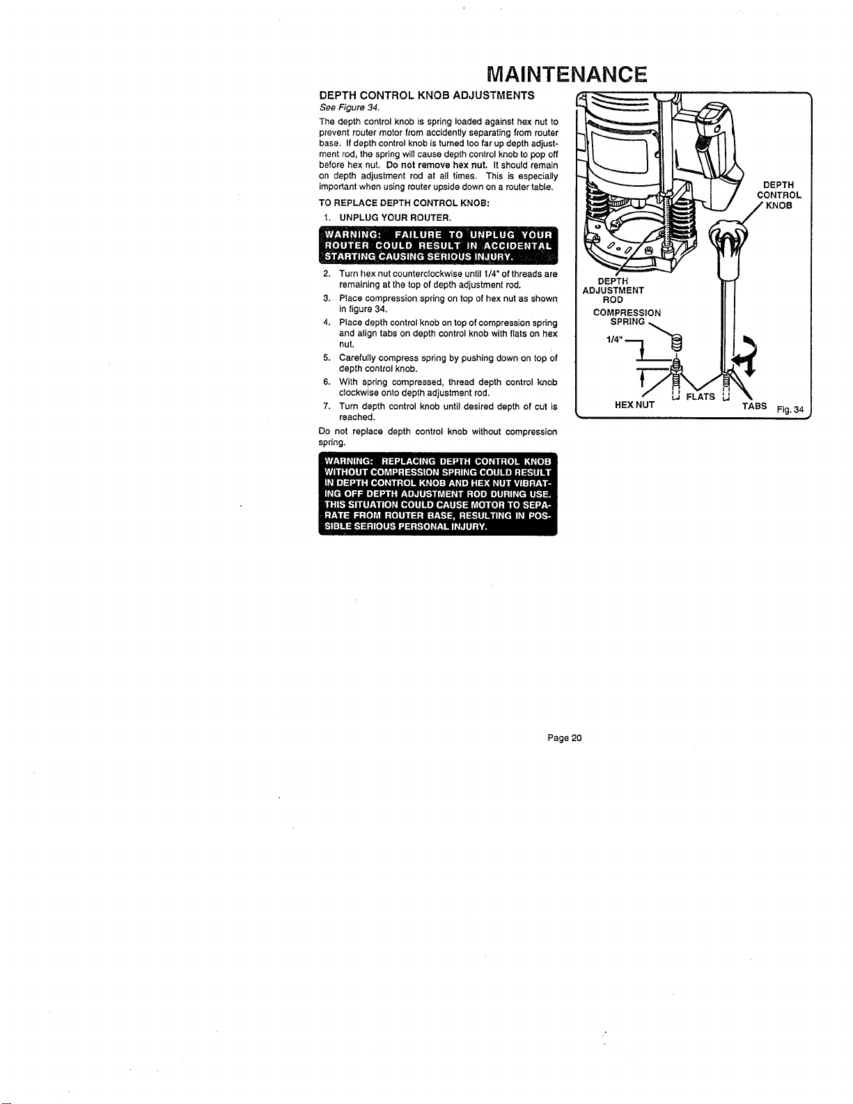
MAINTENANCE
DEPTH CONTROL KNOB ADJUSTMENTS
See Figure 34.
The depth control knob is spring loaded against hex nut to
prevent router motor from accidentlyseparating from muter
base. If depth control knobis turned toofar up depth adjust-
ment rod, the springwill cause depth control knob to pop off
before hex nut. Do not remove hex nut. It should remain
on depth adjustment rod at all times. This is especially
important when usingmuter upsidedown on a router table.
TO REPLACE DEPTH CONTROL KNOB:
1. UNPLUG YOUR ROUTER,
2. Turn hex nut counterclockwiseuntil 1/4" of threads are
remaining at the top Ofdepth adjustment rod.
3. Place compression spring on top of hex nut as shown
in figure 34,
4. Place depth control knob on top of compression spdng
and align tabs on depth control knob with flats on hex
nut,
5. Carefully compress spring by pushing down on top of
depth controlknob.
6. With spring compressed, thread depth control knob
clockwise onto depth adjustment rod.
7. Turn depth control knob until desired depth of cut is
reached,
Do not replace depth control knob without compression
spring.
HEX NUT
DEPTH
CONTROL
TABS Fig. 34
Page 20
EXTENSION CORDS
The use of any extension cord will cause some loss of power.
To keep the loss to a minimum and to prevent tool overheat-
ing, follow the recommended cord sizes on the chart at the
dghL When tool is used outdoors, use only extension cords
suitable for outdoor use and so marked. Extension cords are
available at Sears Retail Stores.
Extension Cord Length Wire Size A.W.G.
0-25 Feet 14
25-50 Feet 12
HELPFUL HINTS
_" Always clamp workpiece securely before routing.
A safe operator is one who thinks ahead.
Always wear eye protection when routing.
Make set-up adjustments carefully. Then double checF Measure twice and cut once.
_' Keep cutters clean and properly sharpened.
Don't let familiarity make you careless.
Study all safety rules and do the job safely.
NEVER place your hands in jeopardy.
,/ Make certain clamps can't loosen while in use.
Test difficult set-ups on scrap--Don't waste lumber.
Plan each operation before you begin.
Provide for smoother operation by cleaning your router frequently. Shake router or blow with an air jet to remove
sawdust build-up,
_' THINK SAFETY BY THINKING AHEAD.
ROUTER TABLES
If mounting your router to a router table, use only the three 5/16-18 UNC-2B tapped holes provided in the router base. Use
5/16-18 UNC-2A flat head screws that are 1-1/8" or 1-1/4" long if mounting router to a router table. NOTE: Router subbase
must be removed in order to gain access to the 5/16-18 UNC tapped holes.
The use of Craftsman routers in router tables offered by other manufacturers has not been investigated for
compliance with applicable safety standards.
Page 21
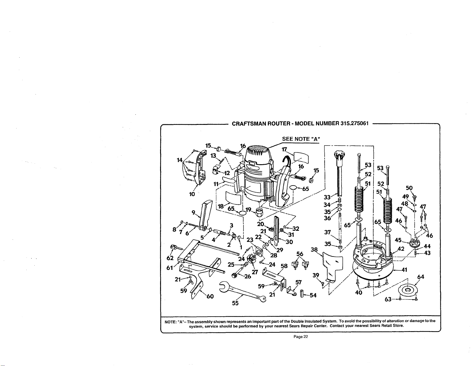
CRAFTSMAN ROUTER - MODEL NUMBER 315.275061
/
10
SEE NOTE"A"
5O
47
38
56 _---43
24 _24
55
NOTE: "A"- The assembly shown represents an important part of the Double Insulated System. To avoid the possibility of alteration or damage to the
system, service should be performed by your nearest Sears Repair Center. Contact your nearest Sears Retail Store.
Page 22
+.
CRAFTSMAN ROUTER - MODEL NUMBER 315.275061
I he model number witl be found on a plate attached to the motor housing. Always mention the model number in alt correspondence regarding your I
ROUTER or when ordering repair parts. SEE BACK PAGE FOR PARTS ORDERING INSTRUCTIONS
J
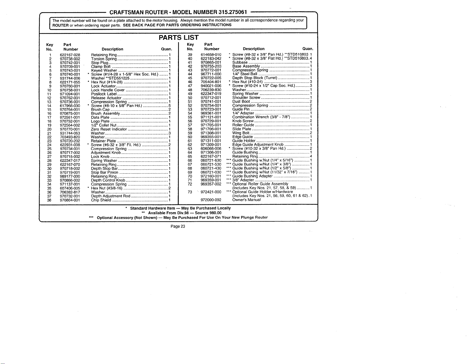
Key PaN
No. Number
1 622167-028
2 970738-002
3 970742-001
4 970709-001
5 970743-O01
6 970740-001
7 931744-006
8 622171-055
9 970760-001
10 970758-001
11 971094-001
12 970762-O01
13 970736-001
14 617966-030
15 970764.001
16 970875-001
17 972561-001
18 970752-001
19 972564-002
20 970770-001
21 931744-063
22 703493-820
23 970720-202
24 622931-008
25 970734-001
26 970717-002
27 970715-002
28 622347-017
29 622167-070
30 970718-002
31 970719-001
32 989177-000
33 970866-002
34 971137-001
35 607406-005
36 706382-817
37 970732-001
38 970864-001
PARTS LIST
Key
Description Quan.
Retaining Ring ............................................... 1
Torsion Spring ............................................... 1
Stop Plug ....................................................... 1
Clamp Bolt .................................................... 1
Keyed Washer .............................................. 1
* Screw (#1/4-28 x 1-5/8" Hex Soc. Hd.) ........ 1
Washer **STD551225 ................................... 1
* Hex Nut (#1/4-28) ......................................... 1
Lock Actuator ................................................ 1
Lock Handle Cover ....................................... 1
Posilock Label ............................................... 1
Release Actuator .......................................... 1
Compression Spring ..................................... 1
* Screw (#8-10 x 5/8" Pan Hd.) ....................... 5
Brush Cap ..................................................... 2
Brush Assembly ............................................ 2
Data Plate ..................................................... !
Logo Plate .................. :.................................. 1.
1/2" Collet Nut ............................................... 1
Zero Reset Indicator ................... .................. 1
Washer ....................... :.................................. 3
Washer ............ :............................................. 1
Retainer Plate ............................................... 1
* Screw (#6-32 x 3/8" Fil+ Hd.) ........................ 2
Compression Spring ..................................... 1
Adjustment Knob ........................................... 1
Lock Knob ..................................................... 1
Spring Washer .............................................. 1
Retaining Ring ............................................... 1
Depth Stop Bar .............................................. 1
Stop Bar Pinion ............................................. 1
Retaining Ring .....; ......................................... 1
Depth Control Knob ....................................... 1
Compression Spring ..................................... 1
* Hex Nut (#3;'8-16) ......................................... 2
Washer .......................................................... 1
Depth Adjustment Rod .................................. 1
Chip Shield .................................................... 1
PaN
No. Number
39 614658-010
40 622183-042
41 970865-001
42 970755-203
43 970772-001
44 967711--000
45 970722-005
46 705404-801
47 940021-006
48 706239-830
49 622347-019
50 970712-001
51 970741-001
52 970754-001
53 970723-001
54 969361.001
55 971121-001
56 970729-001
57 971705-001
58 971706-001
59 971308-001
60 969355-001
61 971311-001
62 971309-001
63 606066.006
64 971306-001
65 622167-071
66 060721-630
67 060721-530
68 060721-430
69 060721-030
70 972160-001
71 969359-001
72 969357-002
73 + 972421.000
Description Quan.
* Screw (#8-32 x 3/8" Pan Hd.) **STD510803 1
* Screw (#8-32 x 3/8" Fiat Hd+) **STD510803.4
Subbase ........................................................ 1
Base Assembly ............................................. 1
Compression Spring ..................................... 1
1/4" Steel Ball ............................................... 1
Depth Stop Block (Turret) ............................. 1
* Hex Nut (#10-24) .......................................... 3
* Screw (#10-24 x 1/2" Cap Soc. Hd.) ............. 3
Washer .......................................................... 1
Spring Washer .............................................. 1
Shoulder Screw ............................................. 1
Dust Boot ...................................................... 2
Compression Spring ..................................... 2
Guide Pin ...................................................... 2
1/4" Adapter .................................................. 1
Combination Wrench (3/8" - 7/8") ................. 1
Knob Screw ................................................... 2
Roller Guide .................................................. 1
Slide Plate ..................................................... 1
Wing Bolt ....................................................... 2
Edge Guide ................................................... 1
Guide Holder ................................................. 1
Edge Guide Adjustment Knob ....................... 1
* Screw (#10-32 x 3/8" Pan Hd.) ..................... 2
Guide Bushing .................. ,............................ 1
Retaining Ring ............................................... 4
*** Guide Bushing w.'Nut (I/4" x 5/16") .............. 1
*** Guide Bushing w/Nut (1/4" x 3/8") ................ 1
*** Guide Bushing w/Nut (1/2" x 5/8") ................ 1
*** Guide Bushing w/Nut (11/32" x 7/16") .......... 1
*** Guide Bushing Adapter ................................. 1
*** 3/8" Adapter .................................................. 1
*** Optional Roller Guide Assembly
(Includes Key Nos. 21, 57, 58, & 59) ............ 1
*** Optional Guide Holder w/Hardware
(Includes Key Nos. 21, 56, 59, 60, 61 & 62). 1
Owner's Manual972000-092
* Standard Hardware Item-- May Be Purchased Locally
** Available From Div.98 -- Source 980.00
*** Optional Accessory (Not Shown) -- May Be Purchased For Use On Your New Plunge Router
Page 23
_A/k&g
OWNER'S
MANUAL
SERVICE
MODELNO.
315.275061
HOW TO ORDER
REPAI R PARTS
Industrial Electronic
Plunge Router
Double Insulated
Now that you have purchased your router, should a need
ever exist for repair parts or service, simply contact any
Sears Service Center and most Sears, Roebuck and Co.
stores. Be sure to provide all pertinent facts when you
call or visit.
The model number of your router will be found on a plate
attached to the motor housing.
WHEN ORDERING REPAIR PARTS, ALWAYS GIVE
THE FOLLOWING INFORMATION:
• PART NUMBER
• PART DESCRIPTION
• MODEL NUMBER • NAME OF ITEM
315.275061 Industrial Electronic
Plunge Router
All parts listed may be ordered from any Sears Service
Center and most Sears stores.
If the parts you need are not stocked locally, your order
will be electronically transmitted to a Sears Repair Parts
Distribution Center for handling.
SEARS, ROEBUCK AND CO., Hoffman Estates, IL 60179