perator s
P R 0 F E S S I 0 N A
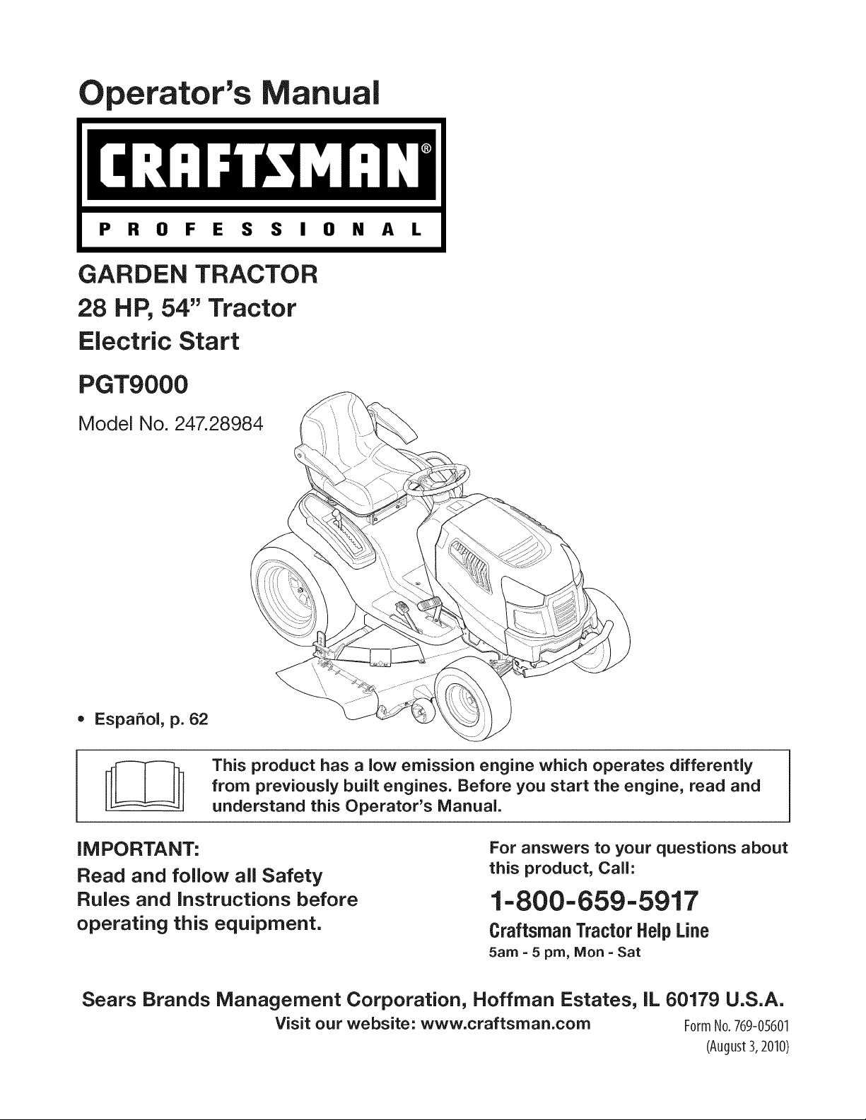
GARDEN TRACTOR
28 HP, 54" Tractor
Electric Start
PGT9000
Model No. 247.28984
= EspaSol, p. 62
This product has a low emission engine which operates differently
from previously built engines. Before you start the engine, read and
understand this Operator's Manual.
iMPORTANT:
Read and foJlow aJJSafety
RuJes and instructions before
operating this equipment,
For answers to your questions about
this product, Call:
1=800=659=5917
Craftsman Tractor Help Line
5am = 5 pro, Mort =Sat
Sears Brands Management Corporation, Hoffman Estates, IL 60179 U,S,A,
Visit our website: www.craftsman.com FormNo.759-0%01
(August3,2010)
Warranty Statement .......................................................... 2
Safety Instructions ............................................................ 3
Slope Guide ....................................................................... 8
Safety Labels .................................................................... 9
Assembly ......................................................................... 10
Know your Lawn Mower .................................................. 13
Operation ........................................................................ 16
Service and Maintenance .............................................. 19
Off-Season Storage ........................................................ 30
Troubleshooting .............................................................. 31
Parts List ......................................................................... 34
Espa_oi ............................................................................ 62
Service Numbers ............................................. Back Cover
CRAFTSMAN PROFESSIONAL FULL WARRANTY
Whenoperatedand maintainedaccordingto allsuppliedinstructions,if any non-expendablepartof thisridingequipmentfailsdueto a defectin
materialor workmanshipwithintwo yearsfrom thedate orpurchase,call 1-800-659-5917to arrangefor free in-homerepair.
Theframe and frontaxle will be repairedfreeof chargefor fiveyearsfromthe dateof purchaseif defectivein materialor workmanship.
Allof the abovewarrantycoverageappliesfor onlyone yearfromthedateof purchaseif this ridingequipmentis everusedfor commercialor
rentalpurposes.
in allcases,if repairprovesimpossible,the ridingequipmentwill be replacedfree of chargewiththe sameoran equivalentmodel.
The batterywill be replacedfree of chargefor 90 daysfromthe dateof purchaseif defectivein materialor workmanship(ourtestingprovesthat it
will nothold a charge).
ThiswarrantycoversONLYdefectsin materialandworkmanship.Searswill NOTpayfor:
• Expendableitemsthat becomewornduringnormaluse,includingbutnot limitedto blades,sparkplugs,aircleaners,belts,and oil filters.
• Standardmaintenanceservicing,oilchanges,or tune-ups.
• Tire replacementor repaircausedby puncturesfrom outsideobjects,suchas nails,thorns,stumps,or glass.
• Tireor wheelreplacementor repairresultingfromnormalwear,accident,orimproperoperationor maintenance.
• Repairsnecessarybecauseof operatorabuse,includingbutnot limitedto damagecausedby towingobjectsbeyondthe capabilityof the
ridingequipment,impactingobjectsthat bendtheframe or crankshaft,or over-speedingthe engine.
Repairsnecessarybecauseof operatornegligence,includingbut not limitedto,electricaland mechanicaldamagecausedby improper
storage,failureto usethe propergradeandamountof engineoil, failureto keepthe deckclearof flammabledebris,or failureto maintainthe
ridingequipmentaccordingto the instructionscontainedin theoperator'smanual.
• Engine(fuelsystem)cleaningor repairscausedbyfuel determinedto becontaminatedoroxidized(stale).In general,fuel shouldbeused
within30 daysof itspurchasedate.
• Normaldeteriorationandwearof the exteriorfinishes,or productlabel replacement.
Thiswarrantyappliesonly whilethis productis withinthe UnitedStates.
Thiswarrantygivesyou specificlegalrights,and you mayalso haveotherrightswhich varyfromstateto state.
Sears Brands ManagementCorporation, HoffmanEstates, IL 60179
GrossHP: 28
EngineOil: SAE30
Fuel: UnleadedGasoline
SparkPlug: Champion®RC12YC
Engine: Briggs& StrattonProfessionalSeries
Model Number
Serial Number
Dateof Purchase
Recordthe modelnumber,serialnumber,
anddateof purchaseabove.
© KCD IR LLC 2
Thissymbolpointsout importantsafetyinstructionswhich,if not
followed,couldendangerthepersonalsafetyand/orpropertyof
yourselfandothers. Readand followall instructionsin thismanual
beforeattemptingto operatethis machine.Failureto complywith
theseinstructionsmayresultin personalinjury.Whenyou seethis
symbol,HEEDITSWARNING!
CALIFORNIA PROPOSITION 65
EngineExhaust,someof itsconstituents,andcertainvehicle
componentscontainoremitchemicalsknownto Stateof California
to cause cancerandbirthdefectsor other reproductiveharm.
Batteryposts,terminals,and relatedaccessoriescontainleadand
leadcompounds,chemicalsknownto the Stateof Californiato
causecancerandreproductiveharm.Washhandsafterhandling.
Thismachinewasbuiltto be operatedaccordingto the safeopera-
tion practicesin this manual.As with anytypeof powerequipment,
carelessnessorerroron the partof the operatorcan resultin serious
injury.Thismachineis capableof amputatingfingers,hands,toes
andfeetandthrowingdebris.Failureto observethe followingsafety
instructionscouldresultin seriousinjuryor death.
Your Responsibility--Restrict the useof this powermachineto
personswho read,understandandfollowthewarningsand instruc-
tionsin thismanualandon the machine.
SAVE THESE INSTRUCTIONS!
GENERAL OPERATION
• Read,understand,andfollowall instructionson the machineand
in themanual(s)beforeattemptingto assembleand operate.
Keepthis manualin a safeplacefor futureand regularreference
andfor orderingreplacementparts.
• Befamiliarwithall controlsandtheir properoperation.Knowhow
to stop the machineand disengagethemquickly.
• Neverallowchildrenunder 14 yearsold to operatethis machine.
Children14yearsoldandover shouldreadandunderstandthe
operationinstructionsandsafety rulesin this manualand should
betrainedand supervisedbya parent.
• Neverallowadultsto operatethis machinewithoutproper
instruction.
• Tohelp avoidbladecontactor a thrownobjectinjury,keep
bystanders,helpers,childrenand petsat least 75 feetfromthe
machinewhile it is in operation.Stopmachineif anyoneenters
the area.
• Thoroughlyinspectthe areawherethe equipmentis to be used.
Removeallstones,sticks,wire,bones,toys,andotherforeign
objectswhichcouldbe pickedup and thrownby the blade(s).
Thrownobjectscan causeseriouspersonalinjury.
• Planyour mowingpatternto avoiddischargeof materialtoward
roads,sidewalks,bystandersandthe like.Also,avoiddischarg-
ingmaterialagainstawall orobstructionwhichmaycause
dischargedmaterialto ricochetbacktowardthe operator.
• Alwayswear safetyglassesor safetygogglesduringoperation
andwhile performingan adjustmentor repairto protectyoureyes.
Thrownobjectswhich ricochetcancauseseriousinjuryto the
eyes.
• Wearsturdy,rough-soledwork shoesand close-fittingslacksand
shirts.Loosefittingclothesandjewelrycanbe caughtin movable
parts.Neveroperatethismachinein bare feet orsandals.
• Be awareof the mowerand attachmentdischargedirectionand
do not pointit at anyone.Donot operatethe mowerwithoutthe
dischargecoverorentiregrasscatcherin its properplace.
Donot put handsor feet near rotatingpartsor underthe cutting
deck. Contactwith the blade(s)can amputatehandsandfeet.
A missingor damageddischargecovercan causeblade contact
or thrownobjectinjuries.
• Stoptheblade(s)whencrossinggraveldrives,walks,or roads
andwhile notcuttinggrass.
• Watchfor trafficwhenoperatingnearor crossingroadways.This
machineis not intendedfor useonany public roadway.
• Donot operatethe machinewhile underthe influenceof alcohol
or drugs.
• Mowonly indaylightorgood artificiallight.
Nevercarrypassengers.
• Disengageblade(s)beforeshiftinginto reverse.Backup slowly.
Alwayslookdownand behindbeforeand while backingto avoida
back-overaccident.
3
• Slowdownbeforeturning.Operatethe machinesmoothly.Avoid
erraticoperationand excessivespeed.
Disengageblade(s),setparkingbrake,stopengine and waituntil
the blade(s)come to a completestopbeforeremovinggrass
catcher,emptyinggrass,uncloggingchute,removinganygrassor
debris,or makinganyadjustments.
Neverleavea runningmachineunattended.Alwaysturnoff
blade(s),setparkingbrake,stopengine and removekey before
dismounting.
Useextracare whenloadingorunloadingthe machineintoa
traileror truck. Thismachineshouldnot bedrivenupor down
ramp(s),becausethe machinecouldtip over,causingserious
personalinjury.The machinemustbe pushedmanuallyon
ramp(s)to loador unloadproperly.
Mufflerandenginebecomehotand can causea burn.Do not
touch.
Checkoverheadclearancescarefullybeforedrivingunderlow
hangingtree branches,wires,door openingsetc., wherethe
operatormaybestruckor pulledfromthe machine,whichcould
resultinseriousinjury.
Disengageallattachmentclutchesanddepressthe brakepedal
completelybeforeattemptingto start engine.
Yourmachineisdesignedto cut normalresidentialgrassof a
heightno morethan 10".Do not attemptto mowthroughunusually
tall,dry grass(e.g.,pasture)or piles of dry leaves.Dry grass or
leavesmaycontactthe engineexhaustand/or builduponthe
mowerdeckpresentinga potentialfire hazard.
Useonlyaccessoriesandattachmentsapprovedfor this machine
by the machinemanufacturer.Read,understandand followall
instructionsprovidedwiththe approvedaccessoryor attachment.
Fora list of approvedaccessoriesandattachments,call 1-800-
659-5917.
Dataindicatesthatoperators,age 60 years andabove,are
involvedin a largepercentageof riding mower-relatedinjuries.
Theseoperatorsshouldevaluatetheirabilityto operatethe riding
mowersafelyenoughto protectthemselvesandothersfrom
seriousinjury.
If situationsoccurwhicharenot coveredinthismanual,usecare
andgoodjudgment.Contact1-800-659-5917for informationand
assistance.
SLOPE OPERATION
Slopesare a majorfactorrelatedto loss of controland tip-over
accidentswhichcan result in severeinjuryor death.Allslopes require
extracaution.If youcannotbackup the slopeor if youfeel uneasyon
it, do not mowit.
Foryoursafety,use the SlopeGuideincludedas partof this manual
to measureslopesbeforeoperatingthis machineona slopedor hilly
area. If the slopeis greaterthan15degreesas shownonthe Slope
Guide,do notoperatethis machineonthatarea or seriousinjurycould
result.
Do:
o
Mowupanddown slopes,not across.Exerciseextremecaution
whenchangingdirectionon slopes.
• Watchfor holes,ruts,bumps,rocks,orother hiddenobjects.
Uneventerraincouldoverturnthe machine.Tallgrasscan hide
obstacles.
Useslowspeed.Choosea lowenoughspeedsettingso that
you will nothaveto stopor shiftwhileon the slope.Tiresmay
lose tractionon slopeseventhoughthe brakesarefunctioning
properly.Alwayskeepmachinein gearwhen goingdownslopes
to take advantageof enginebrakingaction.
• Followthe manufacturer'srecommendationsfor wheelweights
or counterweightsto improvestability.Forrecommendations,call
1-800-659-5917.
• Useextra carewithgrass catchersor otherattachments.These
can changethe stabilityof the machine.
Keepallmovementonthe slopesslowandgradual.Do not make
suddenchangesin speedor direction.Rapidengagementor
brakingcouldcausethe frontof the machineto lift and rapidlyflip
overbackwardswhich couldcauseseriousinjury.
• Avoidstartingorstoppingona slope.If tires losetraction,disen-
gagethe blade(s)and proceedslowlystraightdownthe slope.
DoNot:
• Donot turnon slopesunlessnecessary;then,turnslowlyand
graduallydownhill,if possible.
• Donot mowneardrop-offs,ditchesor embankments.The mower
could suddenlyturnover if a wheelis overthe edgeof a cliff,
ditch,or if an edgecavesin.
• Donot try to stabilizethe machineby puttingyourfooton the
ground.
• Donot usea grass catcheron steepslopes.
• Donot mowon wetgrass.Reducedtractioncouldcausesliding.
• Donot attemptto coastdownhill.Over-speedingmaycausethe
operatorto lose controlof the machineresultingin seriousinjury
or death.
• Donot towheavypull behindattachments(e.g.loadeddumpcart,
lawn roller,etc.)on slopesgreaterthan5 degrees.Whengoing
down hill,the extraweighttendsto pushthe tractorandmay
causeyou to loosecontrol.(e.g.tractormayspeedup,braking
and steeringabilityare reduced,attachmentmayjack-knifeand
causetractorto overturn).
4

CHILDREN
Tragicaccidentscanoccur ifthe operatoris notalert to the presence
of children.Childrenareoftenattractedto the machineand the mowing
activity.Theydo notunderstandthe dangers.Neverassumethat
childrenwill remainwhereyou lastsawthem.
• Keepchildrenout of the mowingareaand inwatchfulcare of a
responsibleadultotherthanthe operator.
• Bealert and turnmachineoff ifa childentersthe area.
• Beforeand whilebacking,lookbehindand downfor small
children.
Nevercarrychildren,evenwith the blade(s)shutoff.Theymay
fall off andbe seriouslyinjuredorinterferewithsafemachine
operation.
• Useextremecarewhenapproachingblind corners,doorways,
shrubs,treesorotherobjectsthat may blockyourvisionof a child
whomay run intothe machine.
Toavoidback-overaccidents,alwaysdisengagethe cutting
blade(s)beforeshiftingintoReverse.Ifequipped,the "Reverse
CautionMode"(bladesoperatewhilemachineridesinreverse)
shouldnotbe usedwhenchildrenor othersare around.
Keepchildrenaway fromhotor runningengines.They cansuffer
burnsfroma hotmuffler.
• Removekeywhenmachineisunattendedto preventunauthorized
operation.
Neverallowchildrenunder 14 yearsof ageto operatethis machine.
Children14andovershouldreadand understandthe instructionsand
safeoperationpracticesin this manualand on the machineandshould
betrainedand supervisedbyan adult.
TOWING
Towonlywith a machinethat hasa hitchdesignedfor towing.Do
not attachtowedequipmentexceptat the hitchpoint.
Followthe manufacturersrecommendationforweightlimitsfor
towedequipmentandtowingonslopes.For recommendations,
call 1-800-659-5917.
Neverallowchildrenor othersin or on towedequipment.
Onslopes,theweightof thetowedequipmentmaycauselossof
tractionandlossof control.
Alwaysuseextra cautionwhentowingwitha machinecapableof
makingtightturns(e.g."zero-turn"ride-onmower). Makewide
turnsto avoidjack-knifing.
Travelslowlyand allowextradistanceto stop.
Do notcoastdownhill.
SERVICE
SafeHandlingof Gasoline
Toavoidpersonalinjuryorpropertydamageuse extremecarein
handlinggasoline.Gasolineisextremelyflammableand the vaporsare
explosive.Seriouspersonalinjurycanoccur whengasolineis spilled
on yourselforyour clotheswhich can ignite.Washyourskinand
changeclothesimmediately.
• Useonly anapprovedgasolinecontainer.
Neverfill containersinsidea vehicleoron a truckortrailer bed
witha plasticliner.Alwaysplacecontainerson the groundaway
fromyourvehiclebeforefilling.
Whenpractical,removegas-poweredequipmentfromthe truck
or trailerand refueliton theground.Ifthis isnot possible,then
refuelsuchequipmentona trailerwitha portablecontainer,rather
than froma gasolinedispensernozzle.
Keepthe nozzleincontactwith the rim of the fueltankor
containeropeningat all timesuntilfuelingiscomplete.Donot use
a nozzlelock-opendevice.
Extinguishall cigarettes,cigars,pipesand othersourcesof
ignition.
• Neverfuel machineindoors.
Neverremovegascap or addfuelwhilethe engineis hotor run-
ning.Allowengineto coolat leasttwominutesbeforerefueling.
Neveroverfill fuel tank. Filltank to no morethan 1/2inchbelow
bottomof filler neckto allowspace forfuel expansion.
• Replacegasolinecap andtightensecurely.
• If gasolineis spilled,wipeitoff the engineandequipment.Move
machineto anotherarea.Wait 5 minutesbeforestartingthe
engine.
• To reducefire hazards,keepmachinefree of grass,leaves,or
otherdebrisbuild-up.Cleanup oil or fuel spillageand removeany
fuel soakeddebris.
• Neverstorethe machineor fuelcontainerinsidewherethere isan
openflame,sparkor pilotlight as on a waterheater,spaceheater,
furnace,clothesdryeror othergasappliances.
Allowa machineto coolat leastfiveminutesbeforestoring.
GeneralService
• Neverrunanengineindoorsorinapoorlyventilatedarea.Engine
exhaustcontainscarbonmonoxide,anodorless,anddeadlygas.
• Beforecleaning,repairing,orinspecting,makecertainthe
blade(s)andallmovingpartshavestopped.Disconnectthespark
plugwireandgroundagainsttheenginetopreventunintended
starting.
• Periodicallychecktomakesurethebladescometocomplete
stopwithinapproximately(5)fivesecondsafteroperatingthe
bladedisengagementcontrol.Ifthebladesdonotstopwithinthe
thistimeframe,yourmachineshouldbeservicedprofessionally
byaSearsorotherqualifiedservicedealer.
• Checkbrakeoperationfrequentlyasitissubjectedtowearduring
normaloperation.Adjustandserviceasrequired.
• Checktheblade(s)andenginemountingboltsatfrequent
intervalsforpropertightness.Also,visuallyinspectblade(s)
fordamage(e.g.,excessivewear,bent,cracked).Replacethe
blade(s)withtheoriginalequipmentmanufacturer's(O.E.M.)
blade(s)only,listedinthismanual.Useofpartswhichdonot
meettheoriginalequipmentspecificationsmayleadtoimproper
performanceandcompromisesafety!
• Mowerbladesaresharp.Wrapthebladeorweargloves,anduse
extracautionwhenservicingthem.
• Keepallnuts,bolts,andscrewstighttobesuretheequipmentis
insafeworkingcondition.
• Nevertamperwiththe safetyinterlocksystemor othersafety
devices.Checktheir properoperationregularly.
• Afterstrikinga foreignobject,stop the engine,disconnectthe
sparkplugwire(s)andgroundagainstthe engine.Thoroughly
inspectthe machinefor anydamage.Repairthe damagebefore
startingandoperating.
• Neverattemptto makeadjustmentsor repairsto the machine
whilethe engineis running.
• Grasscatchercomponentsandthe dischargecoverare subject
to wearand damagewhich couldexposemovingparts or allow
objectsto bethrown.Forsafetyprotection,frequentlycheck
componentsand replaceimmediatelywithoriginalequipment
manufacturer's(O.E.M.)partsonly,listed in this manual.Use of
partswhichdo not meetthe originalequipmentspecificationsmay
leadto improperperformanceandcompromisesafety!
• Donot changethe enginegovernorsettingsorover-speedthe
engine.The governorcontrolsthe maximumsafe operatingspeed
of the engine.
Maintainor replacesafetyandinstructionlabels,as necessary.
• Observeproperdisposallawsandregulationsfor gas,oil, etc.to
protecttheenvironment.
• Accordingto the ConsumerProductsSafetyCommission(CPSC)
andthe U.S.EnvironmentalProtectionAgency(EPA),this product
has an AverageUsefulLifeof seven(7)years,or 390hours
of operation.At the endof the AverageUsefulLife,buy anew
machineor havethe machineinspectedannuallybya Searsor
otherqualifiedservicedealerto ensurethatall mechanicaland
safetysystemsareworkingproperlyandnot wornexcessively.
Failureto do so can resultinaccidents,injuriesor death.
DO NOT MODIFY ENGINE
Toavoid seriousinjuryor death,do notmodifyengine inanyway.
Tamperingwiththe governorsettingcanlead to a runawayengineand
causeit to operateat unsafespeeds.Nevertamperwithfactorysetting
of enginegovernor.
NOTICE REGARDING EMISSIONS
Engineswhicharecertifiedto complywith Californiaand federal
EPAemissionregulationsfor SORE(SmallOffRoadEquipment)are
certifiedto operateon regularunleadedgasoline,and mayinclude
the followingemissioncontrol systems:EngineModification(EM)and
ThreeWay Catalyst(TWO)if so equipped.
SPARK ARRESTOR
Thismachineis equippedwith an internalcombustionengineand
shouldnotbe usedon or nearanyunimprovedforest-covered,
brushcoveredorgrass-coveredlandunlessthe engine'sexhaust
systemisequippedwith a sparkarrestormeetingapplicablelocalor
statelaws (if any).
Ifa sparkarrestoris used,it shouldbe maintainedin effectiveworking
orderby the operator.Inthe Stateof Californiatheaboveis required
by law (Section4442of the CaliforniaPublicResourcesCode).Other
statesmayhavesimilarlaws.Federallaws applyonfederallands.
A sparkarrestorfor the muffleris availablethroughyournearestSears
PartsandRepairServiceCenter.
6
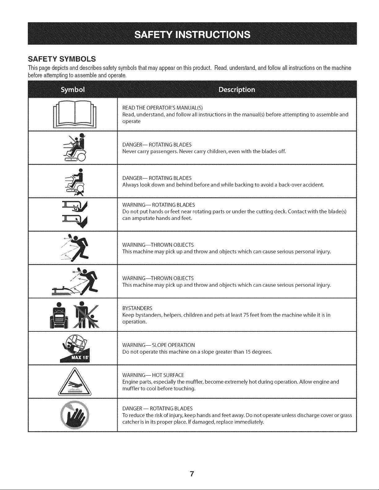
SAFETY SYMBOLS
Thispagedepictsand describessafety symbolsthat mayappearonthis product. Read,understand,andfollowallinstructionson the machine
beforeattemptingto assembleand operate.
0
A
READ THE OPERATOR'S MANUAL(S)
Read, understand, and follow all instructions in the manual(s) before attempting to assemble and
operate
DANGER-- ROTATING BLADES
Never carry passengers. Never carry children, even with the blades off.
DANGER-- ROTATING BLADES
Always look down and behind before and while backing to avoid a back-over accident.
WARNING-- ROTATING BLADES
Do not put hands or feet near rotating parts or under the cutting deck. Contact with the blade(s)
can amputate hands and feet.
WARNING--THROWN OBJECTS
This machine may pick up and throw and objects which can cause serious personal injury.
WARNING--THROWN OBJECTS
This machine may pick up and throw and objects which can cause serious personal injury.
BYSTANDERS
Keep bystanders, helpers, children and pets at least 75 feet from the machine while it is in
operation.
WARNING-- SLOPE OPERATION
Do not operate this machine on a slope greater than 15 degrees.
WARNING-- HOT SURFACE
Engine parts, especially the muffler, become extremely hot during operation. Allow engine and
muffler to cool before touching.
DANGER-- ROTATING BLADES
To reduce the risk of injury, keep hands and feet away. Do not operate unless discharge cover or grass
catcher is in its proper place. If damaged, replace immediately.
7

SLOPE GUIDE
}=.==
m
(=)
}====
G.)
1>
0_3
_==
(3)
OO
_==
C:)
_=
_==
0_3
=,F=_
03
_==
c_3
%,==,==
C)
}===
(1)
_==
}==,==
C)
(=3
c_3
}====
C)
_r
Or)
C;)
(=)
(==
CL)
%,==,=
c_3
}====
C)
_r
I
I
I
I
I
I
I
Dm m_
I
I
i
I
I
I
I
!
I
l
l
l
l
l
l
l
l
0
c
E
Q
8
o
(....
"'O
C3,
(1)
(1)
&
1>-.
03
E
x
o
cL (1)
03 cL
o co
"_--- (D
03 O
v_
_2
--_ o
cz o
03 "o
o
_E
(-" 03
o_
CZ3cL
o__
_._o
o
8
ROTATING BLADES CAUSE
_HEN CHI_REHOROTHERSARE
AROUND I •
_HILDREN EVENWITHBLADE(S)OFF.J
_HIND BEFOREANDWHILE J
BACKING. I
_RSE ISNOT RECOMMENDED, I
1. DISENGAGE BLADES/PTO, (POWER TAKE OFF)
2. ENGAGE THE TRACTOR'S PARKING BRAKE.
3. ACTIVATE THROTTLE TO RUN SETTING,
(MAN. SETTING NOT RECOMMENDED).
4. TURN KEY TO START ENGINE, AFTER START RELEASE KEY.
YOU MUST DISENGAGE SLADES/PTO, (FO_ TAKE OFF)
BEFORE TRAVELING IN REVERSE.
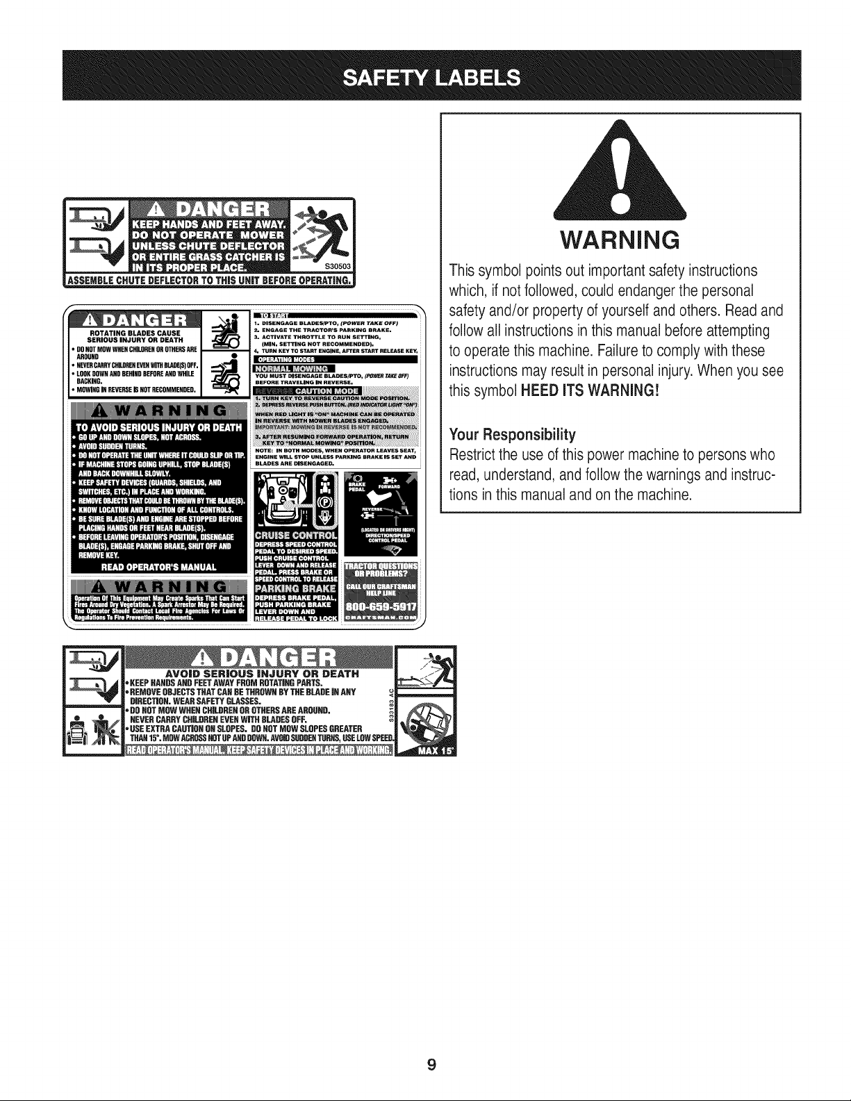
WARNING
This symbol points out important safety instructions
which, if not followed, could endanger the personal
safety and/or property of yourself and others. Readand
follow all instructions in this manual before attempting
to operatethis machine. Failureto comply with these
instructions may result in personal injury.When you see
this symbol HEED ITS WARNING!
Your Responsibility
Restrictthe use of this power machineto persons who
read, understand, and follow the warnings and instruc-
tions in this manualand on the machine.
AVO|D SER|OUS |HJURY OR DEATH
"KEEPHANDSAHDFEETAWAYFROMROTATIRGPARTS.
'=REMOVEOBJECTSTHATCARDETHROWNBYTHEBLADEJRANY
DIRECTIOR.WEARSAFETYGLASSES.
'=DOROTMOWWHENCHILDRENOROTHERSAREAROUND,
NEVERCARRYCHILDRENEVERWITHBLADESOFF.
"USEEXTRACAUTIORONSLOPES.DOROTMOWSLOPESGREATER
THAH15°. MOWACROSSHOTUPANDDDWR.AVOIDSUDDERTURNS,USELOWSPEE
m
m
9

Connecting the Battery Cables Checking Tire Pressure
Batteryposts,terminals,and relatedaccessoriescontainleadand
leadcompounds,chemicalsknownto the Stateof Californiato cause
cancerandreproductiveharm.Washhandsafterhandling.
Whenattachingbatterycables,alwaysconnectthe POSiTiVE(Red)
wire to its terminalfirst,followedbythe NEGATIVE(Black)wire.
For shippingreasons,bothbatterycablesonyourequipmentmay
havebeenleft disconnectedfromtheterminalsat the factory.To
connectthe batterycables,proceedas follows:
NOTE:The positivebatteryterminalis markedPos.(+). The negative
batteryterminalis markedNeg.(-).
NOTE: If the positivebatterycableis alreadyattached,skip aheadto
step2.
1. Removetheplasticcover,if present,fromthe positivebattery
terminalandattachthe redcable to the positivebatteryterminal
(+)with the bolt andhexnut.See Figure3.
f
.\
Figure3
2. Removetheplasticcover,if present,fromthe negativebattery
terminalandattachthe blackcableto the negativebattery
terminal(-) withthe bolt and hex nut.SeeFigure3.
3. Positionthe red rubberbootoverthe positivebatteryterminalto
helpprotectit fromcorrosion.
NOTE: If the batteryis put intoserviceafter the dateshownon top/
sided battery,chargethe batteryas instructedinthe Serviceand
Maintenancesectionof this Operator'sManualpriorto operatingthe
tractor.
Neverexceedthe maximuminflationpressureshownon thesidewall
of the tire.Do notoverinfiatetires. Checksidewallof tiresfor maxi-
mumpsi.Equaltire pressureshouldbe maintainedat all times.
The tires onyourtractormaybeoverinfiatedfor shippingpurposes.
Reducethe tire pressurebeforeoperatingthe tractor.Checksidewall
of tires for maximumpsi.
Adjusting the Seat
Toadjust the positionof the seat,pullupand hold the seatadjustment
lever.Slidethe seatforwardor rearwardto thedesiredposition;then
releasethe adjustmentlever.Makesure seatis lockedintopositionin
a seat-stopbeforeoperatingthe tractor.See Figure4.
Beforeoperatingthe tractor,makesurethe seatis engagedin a
seat-stop.Engagethe parkingbrake.Standbehindthe machineand
pull backon seatuntil it clicksintoplace.
Figure4
Toadjust the angleof the armrests,liftthe armrestsand rotatethe
heightadjustknobclockwiseto lowertheangleor counterclockwiseto
raisethe angle.SeeFigure4.
11
Setting the Deck Gauge Wheels and Roller
Movethe tractoron a firm andlevelsurface,preferablypavement,and
proceedas follows
1. Selectthe heightpositionof the cuttingdeck byplacingthedeck
lift leverinthe normallydesiredmowingheightsetting(anyof the
elevendifferentcuttingheightnotcheson the rightfender).
2. Checkthe gaugewheelsforcontactor excessiveclearancewith
the surfacebelow.Thedeckgauge wheelsshouldhavebetween
l_-inchand Y2-inchclearanceabovethe ground.
Ifthe gaugewheelshaveexcessiveclearanceor contactwith the
surface,adjustas follows:
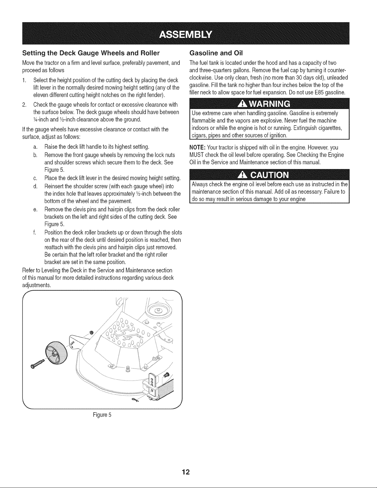
a. Raisethe decklift handleto itshighest setting.
b. Removethe frontgaugewheelsby removingthe locknuts
andshoulderscrewswhichsecurethemto the deck.See
Figure5.
c. Placethedecklift leverinthedesiredmowingheightsetting.
d. Reinsertthe shoulderscrew(witheach gaugewheel)into
the indexholethatleavesapproximatelyY2-inchbetweenthe
bottomof the wheeland the pavement.
e. Removethe clevispins andhairpinclipsfrom thedeck roller
bracketson the left andright sidesof the cuttingdeck.See
Figure5.
f. Positionthe deck rollerbracketsup ordownthroughthe slots
onthe rearof the deckuntildesiredpositionisreached,then
reattachwiththe clevispinsand hairpinclipsjust removed.
Becertainthatthe leftroller bracketand the rightroller
bracketareset inthe same position.
Referto Levelingthe Deckin theServiceand Maintenancesection
of this manualfor moredetailedinstructionsregardingvariousdeck
adjustments.
f
Gasoline and Oil
The fueltank islocatedunderthe hoodand hasa capacityof two
andthree-quartersgallons.Removethefuel cap by turningitcounter-
clockwise.Useonly clean,fresh (no morethan30 daysold), unleaded
gasoline.Fillthe tankno higherthanfour inchesbelowthetop of the
filler neckto allowspacefor fuelexpansion.Donot use E85gasoline.
Useextremecarewhen handlinggasoline.Gasolineisextremely
flammableandthevaporsare explosive.Neverfuel the machine
indoorsor whilethe engineishotor running.Extinguishcigarettes,
cigars,pipesandothersourcesof ignition.
NOTE: Yourtractorisshippedwithoil inthe engine.However,you
MUSTcheckthe oillevelbeforeoperating.See Checkingthe Engine
Oil inthe Serviceand Maintenancesectionof thismanual.
Alwayscheckthe engineoil levelbeforeeach useas instructedinthe
maintenancesectionof this manual.Addoil as necessary.Failureto
do so may resultin seriousdamageto yourengine
Figure5
12
f
FuelTank Cap
Throttle
I
Fuel LevelIndicator
Systems Indicator
Monitor
ignition Switch
Module
PTO(Blade
Knob
Brake Pedal
Seat AdjustmentLever
Parking Brake/
Cruise Control Lever
DrivePedal
Pedal
Lift Lever
Cup Holder"
\
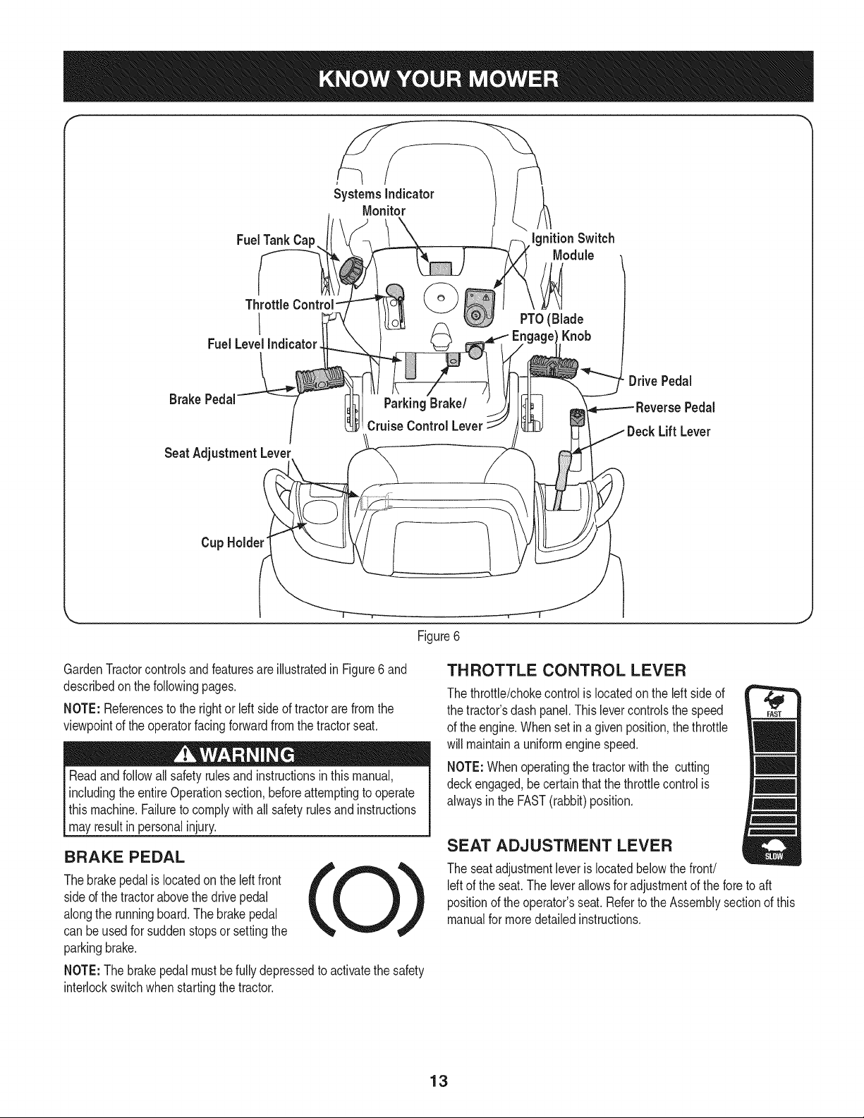
Figure6
GardenTractorcontrolsand featuresare illustratedin Figure6 and
describedon thefollowingpages.
NOTE: Referencesto the rightor Idt sideof tractorare from the
viewpointof theoperatorfacingforwardfromthe tractorseat.
Readand followall safetyrulesand instructionsin this manual,
includingtheentireOperationsection,beforeattemptingto operate
this machine.Failureto complywith all safetyrulesand instructions
mayresultin personalinjury.
BRAKE PEDAL
Thebrakepedalis locatedonthe left front
sideof the tractorabovethe drivepedal
alongthe runningboard.Thebrakepedal
can be usedfor suddenstopsor settingthe
parkingbrake.
NOTE:The brakepedalmust befullydepressedto activatethe safety
interlockswitchwhenstartingthetractor.
THROTTLE CONTROL LEVER
The throttle/chokecontrolis locatedonthe left sideof
the tractor'sdash panel.Thislevercontrolsthe speed
of the engine.Whenset in a givenposition,the throttle
will maintaina uniformenginespeed.
NOTE:Whenoperatingthe tractorwith the cutting
deckengaged,becertainthatthe throttlecontrol is
alwaysin the FAST(rabbit)position.
SEAT ADJUSTMENT LEVER
The seat adjustmentleveris locatedbelowthe front/
leftof the seat.The leverallowsfor adjustmentof the foreto aft
positionof the operator'sseat.Referto the Assemblysectionof this
manualfor moredetailedinstructions.
13
DECK LiFT LEVER
Foundon yourtractor'srightfender,the
decklift leveris usedto changethe height
of the cuttingdeck. Touse, movethe lever
to the left,then placein the notchbest
suitedfor yourapplication.
IGNITION SWITCH MODULE
Tostart theengine,insertthe keyinto
the ignitionswitchand turnclockwise
to the STARTposition.Releasethe
keyintothe NORMALMOWINGMODE
positiononcethe enginehas fired.
Tostop theengine,turnthe ignitionkey
counterclockwiseto the STOPposition.
(BladeEngageknob),setparkingbrake,stopengineand remove
to preventunintendedstarting.
Priorto operatingthe tractor,referto bothSafetyInterlockSwitches
andStartingThe Enginein the Operationsectionof this manual
fordetailedinstructionsregardingthe IgnitionSwitchModuleand
[operatngthe tractor n REVERSECAUTON MODE.
DRIVE PEDAL
Thedrivepedalis locatedon the rightsideof
thetractor,along the runningboard.Pressthe
drivepedalforwardto causethe tractorto travel
forward.Groundspeedis alsocontrolledwith
thedrive pedal.Thefurtherforwardthe pedalis
pivoted,the fasterthe tractorwilltravel.The pedal
will returnto its originalpositionwhenit's not
pressed.
REVERSE PEDAL
The reversepedal is locatedon the right sideof the
tractoralongthe runningboard. Groundspeedis
alsocontrolledwith the reversepedal.Thefurther
downwardthe pedalis pivoted,the fasterthe
tractorwill travel.Thepedalwill returnto its original
positionwhenit's not pressed.
|
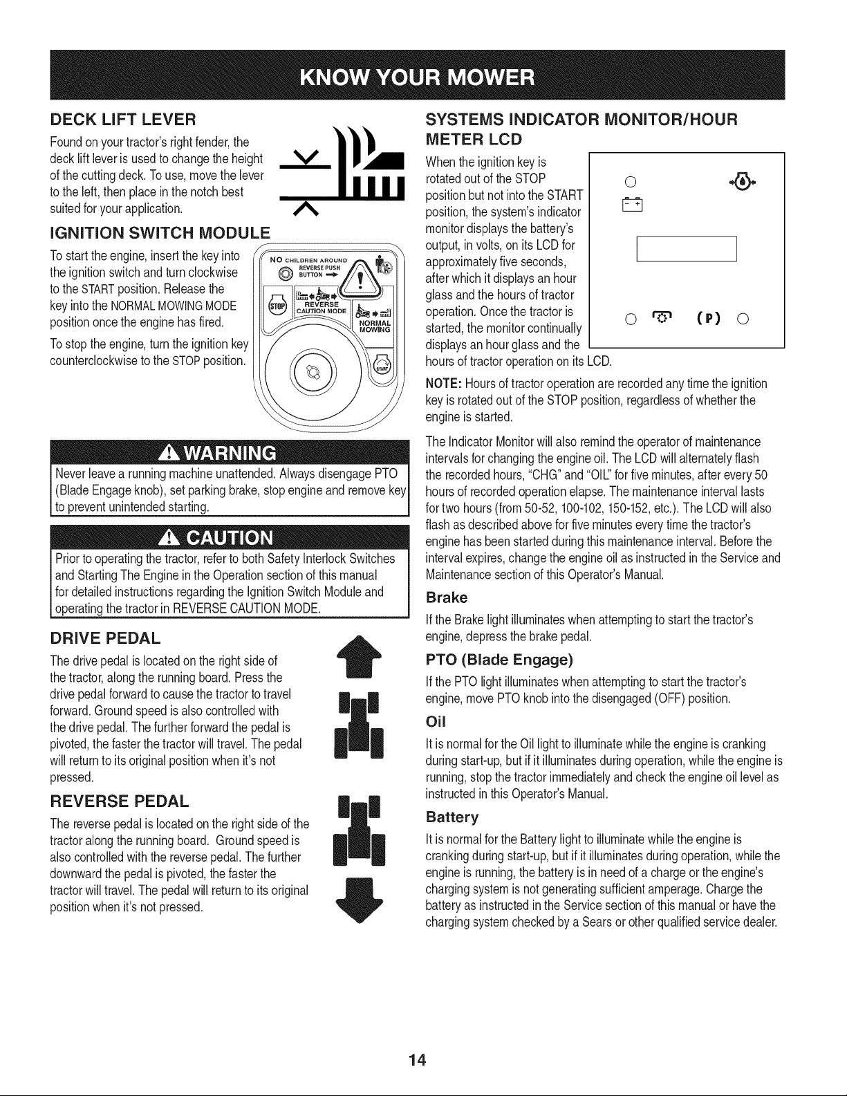
SYSTEMS INDICATOR MONITOR/HOUR
METER LCD
Whenthe ignitionkey is
rotatedout of the STOP
positionbut not intothe START
position,thesystem'sindicator
monitordisplaysthe battery's
output,in volts,on its LCDfor
approximatelyfiveseconds,
afterwhichit displaysan hour
glassandthe hoursof tractor
operation.Oncethe tractoris
started,the monitorcontinually
displaysan hourglassandthe
0
I
o (r) o
hoursof tractoroperationon its LCD.
NOTE: Hoursof tractoroperationare recordedanytime the ignition
keyis rotatedout of the STOPposition,regardlessof whetherthe
engineis started.
The IndicatorMonitorwillalso remindthe operatorof maintenance
intervalsfor changingthe engineoil. The LCDwill alternatelyflash
the recordedhours,"CHG"and"OIL."for five minutes,after every50
hoursof recordedoperationelapse.The maintenanceintervallasts
for two hours(from 50-52, 100-102,150-152,etc.). The LCDwill also
flashas describedabovefor fiveminuteseverytime the tractor's
enginehasbeen startedduring thismaintenanceinterval.Beforethe
intervalexpires,changethe engineoilas instructedin the Serviceand
Maintenancesectionof thisOperator'sManual.
Brake
if the Brakelightilluminateswhenattemptingto start the tractor's
engine,depressthe brakepedal.
PTO (Blade Engage)
Ifthe PTOlight illuminateswhenattemptingto startthe tractor's
engine,movePTOknobinto thedisengaged(OFF)position.
Oil
Itis normalfor the Oillightto illuminatewhile theengineis cranking
duringstart-up,but if it illuminatesduringoperation,whilethe engineis
running,stopthe tractorimmediatelyandcheckthe engineoil levelas
instructedinthis Operator'sManual.
Battery
Itis normalfor the Batterylight to illuminatewhilethe engineis
crankingduringstart-up,but if it illuminatesduringoperation,whilethe
engineis running,the batteryis inneedof a chargeor the engine's
chargingsystemis notgeneratingsufficientamperage.Chargethe
batteryas instructedin the Servicesectionof thismanualor havethe
chargingsystemcheckedby aSearsor otherqualifiedservicedealer.
14
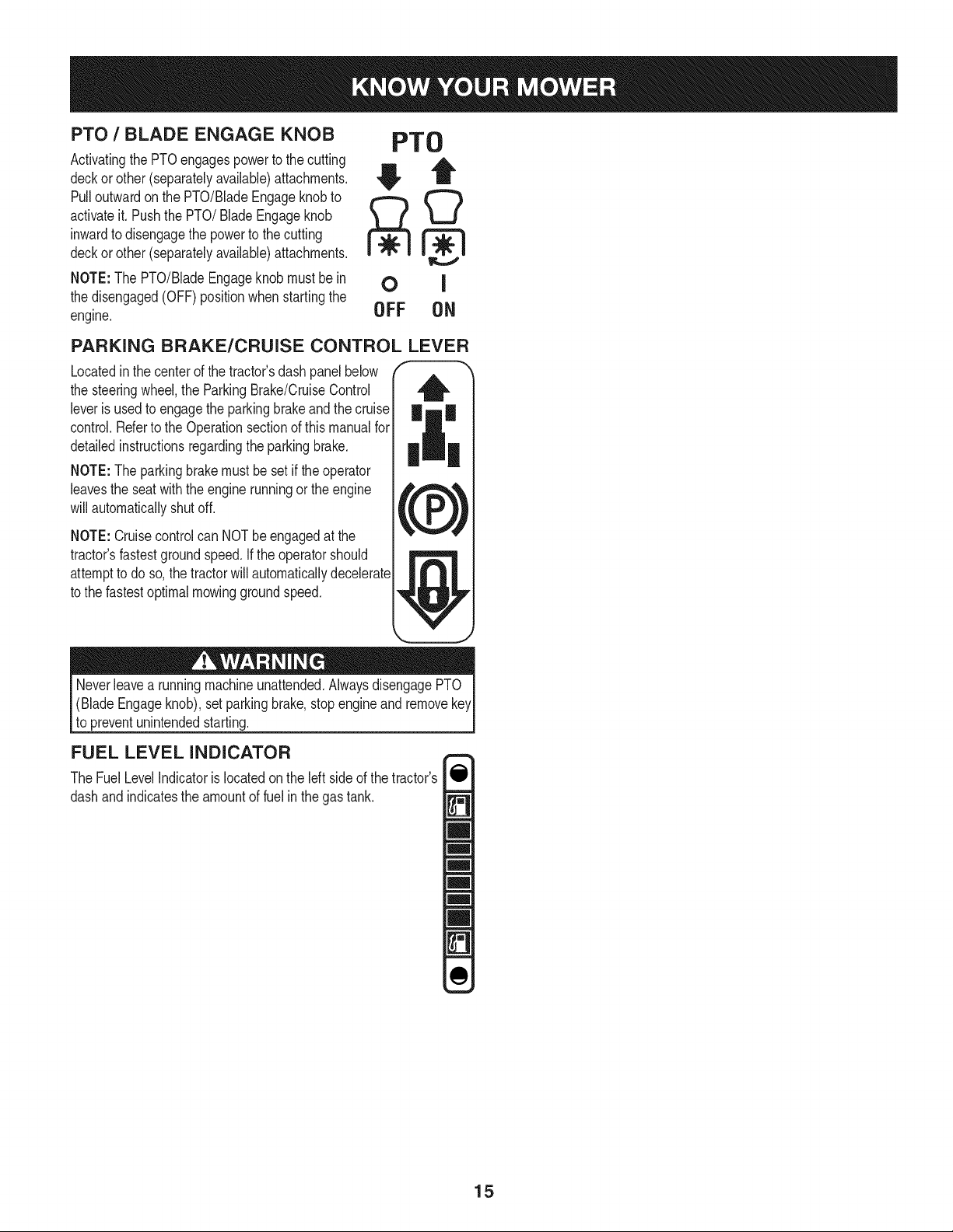
PTO / BLADE ENGAGE KNOB
Activatingthe PTOengagespowerto the cutting
deckorother (separatelyavailable)attachments.
Pulloutwardon the PTO/BladeEngageknobto
activateit.Pushthe PTO/Blade Engageknob
inwardto disengagethe powerto the cutting
deckorother (separatelyavailable)attachments.
NOTE:The PTO/BladeEngageknobmustbe in
the disengaged(OFF)positionwhenstartingthe
engine.
PTO
OFF ON
PARKING BRAKE/CRUISE CONTROL LEVER
Locatedinthe centerof the tractor'sdash panelbelow
the steeringwheel,the ParkingBrake/CruiseControl
leveris usedto engagethe parkingbrakeandthe cruise
control.Referto the Operationsectionof thismanualfor
detailedinstructionsregardingthe parkingbrake.
NOTE:The parkingbrakemustbe setif the operator
leavesthe seatwith the enginerunningor the engine
will automaticallyshutoff.
NOTE:Cruisecontrolcan NOTbe engagedat the
tractor'sfastestgroundspeed.If the operatorshould
attemptto do so,the tractorwill automaticallydecelerate
to the fastestoptimalmowinggroundspeed.
Neverleavea runningmachineunattended.AlwaysdisengagePTO
(BladeEngageknob),setparkingbrake,stop engineand removekey
to preventunintendedstarting.
FUEL LEVEL INDICATOR
The FuelLevelIndicatoris locatedon the leftsideof thetractor's
dashand indicatesthe amountof fuel inthe gastank.
15
SAFETY iNTERLOCK SWITCH ES
Thistractoris equippedwitha safetyinterlocksystemfor the protection
of the operator.Ifthe interlocksystemshouldevermalfunction,do not
operatethe tractor.Contacta Searsorotherqualifiedservicedealer.
• The safetyinterlocksystempreventstheenginefromcrankingor
startingunlessthe parkingbrakeis engaged,and the PTO(Blade
Engage)knobis in thedisengaged(OFF)position.
Theenginewill automaticallyshutoffif theoperatorleavesthe
seatbeforeengagingthe parkingbrake.
• TheelectricPTO(Blade Engage)clutchwill automaticallyshut
off if the operatorleavesthe tractor'sseatwith the PTO(Blade
Engage)knobin the engaged(ON) position,regardlessof
whetherthe parkingbrakeisengaged.
• Withthe ignitionkeyinthe NORMALMOWINGposition,the
electricPTO(BladeEngage)clutchwillautomaticallyshut off if
the PTO(BladeEngage)knobis movedintothe engaged(ON)
positionwiththedrive pedalinpositionfor reversetravel.
Do notoperatethe tractorif the interlocksystemis malfunctioning.
Thissystemwasdesignedfor your safetyandprotection.
STARTING THE ENGINE
NOTE: Referto Gasand Oil in the Assemblysectionof this manual
for Gasolinefill-upinstructions.Referto Checkingthe EngineOil inthe
Serviceand Maintenancesectionof this manualfor oilfill-up instruc-
tions.
1. Insertthe tractorkeyintothe ignitionswitch module.
2. Placethe PTO(BladeEngage)knobin the disengaged(OFF)
position.
3. Engagethe tractor'sparkingbrake.
4. Activatethrottleto runsetting.
Note: Minimumsettingnot recommended.
5. Turnthe ignitionkeyclockwiseto the STARTposition.After
theengine starts,releasethe key.Itwill returnto the NORMAL
MOWINGposition.
Do NOThold the key in the STARTpositionfor longerthan ten
secondsat a time.Doingso maycause damageto yourengine's
electricstarter.
STOPPING THE ENGINE
Ifyou strikea foreignobject,stopthe engineanddisconnectthe
sparkplugwire(s). Thoroughlyinspectthe machinefor anydamage.
Repairthedamagebeforerestartingandoperating.
1. If the bladesare engaged,placethe PTO/BladeEngageknobin
the disengaged(OFF) position.
2. Placethe throttle/chokecontrollevernearthe SLOWposition.
3. Turnthe ignitionkeycounterclockwiseto the STOPposition.
4. Removethe keyfromthe ignitionswitchto preventunintended
starting.
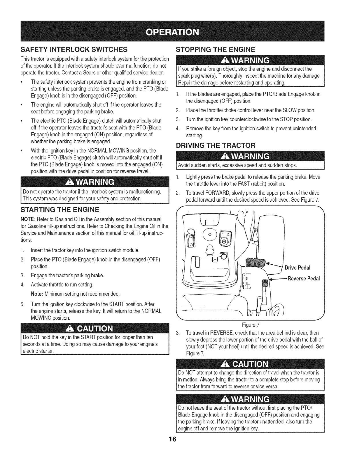
DRIVING THE TRACTOR
Avoidsuddenstarts,excessivespeedand suddenstops.
1. Lightlypressthe brakepedalto releasethe parkingbrake.Move
the throttleleverintothe FAST(rabbit)position.
2. TotravelFORWARD,slowlypressthe upperportionof the drive
pedalforwarduntilthe desiredspeedis achieved.SeeFigure7.
,
Figure7
3. Totravelin REVERSE,checkthatthe areabehindis clear,then
slowlydepressthe lowerportionof the drivepedalwith the ballof
yourfoot (NOTyourheel)untilthe desiredspeedis achieved.See
Figure7.
16
DoNOTattemptto changethe directionof travel whenthetractoris
in motion.Alwaysbringthe tractorto a completestop beforemoving
the tractorfromforwardto reverseor vice versa.
Donot leavethe seat of the tractorwithoutfirst placingthe PTO/
BladeEngageknobin the disengaged(OFF)positionandengaging
the parkingbrake. If leavingthe tractorunattended,alsoturn the
engineoff andremovethe ignitionkey.
REVERSE CAUTION MODE
The REVERSECAUTIONMODEpositionof thekey switchmodule
allowsthe tractorto be operatedin reversewith the blades(PTO)
engaged.
NOTE: Mowingin reverseis not recommended.
Useextremecautionwhile operatingthe tractorin the REVERSE
CAUTIONMODE.Alwayslookdownand behindbeforeandwhile
backing.Do notoperatethe tractorwhenchildrenor othersare
around.Stopthe tractorimmediatelyif someoneentersthearea.
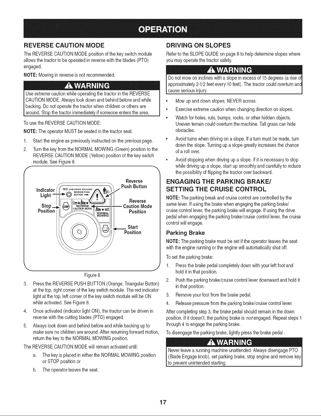
Touse the REVERSECAUTIONMODE:
NOTE:The operatorMUSTbe seatedinthe tractorseat.
1. Start theengineas previouslyinstructedon the previouspage.
2. Turnthe keyfromthe NORMALMOWING(Green)positionto the
REVERSECAUTIONMODE(Yellow)positionof the keyswitch
module.SeeFigure8.
F "
Reverse
Figure8
3. Pressthe REVERSEPUSHBUTTON(Orange,TriangularButton)
at the top,rightcornerof the key switchmodule.The redindicator
lightat the top, leftcornerof the key switchmodulewillbe ON
whileactivated.See Figure8.
4. Onceactivated(indicatorlightON), the tractorcan bedrivenin
reversewiththe cuttingblades(PTO)engaged.
5. Alwayslookdownand behindbeforeand whilebackingupto
makesureno childrenare around.After resumingforwardmotion,
returnthe keyto the NORMALMOWINGposition.
The REVERSECAUTIONMODEwill remainactivateduntil:
a. Thekeyis placedin eitherthe NORMALMOWINGposition
orSTOPpositionor
b. Theoperatorieavesthe seat.
DRIVING ON SLOPES
Referto the SLOPEGUIDEon page8 to helpdetermineslopeswhere
you mayoperatethe tractorsafely.
Donot mowon inclineswitha slopein excessof 15degrees(a rise
approximately2-1/2feetevery10feet).The tractorcouldoverturnanc
causeseriousinjury.
• Mowup anddown slopes,NEVERacross.
• Exerciseextremecautionwhenchangingdirectionon slopes.
• Watchfor holes,ruts,bumps,rocks,or otherhiddenobjects.
Uneventerraincouldoverturnthe machine.Tallgrass can hide
obstacles.
Avoidturns whendrivingon a slope.If a turnmustbe made,turn
downthe slope.Turningup a slopegreatlyincreasesthe chance
of a rollover.
Avoidstoppingwhen drivingup a slope.If itis necessaryto stop
whiledrivingup a slope,start upsmoothlyandcarefullyto reduce
the possibilityof flippingthe tractoroverbackward.
ENGAGING THE PARKING BRAKE/
SETTING THE CRUISE CONTROL
NOTE:Theparkingbreakand cruisecontrolare controlledbythe
samelever.Ifusingthe brakewhenengagingthe parkingbrake/
cruisecontrollever,theparkingbrakewillengage.Ifusingthe drive
pedalwhenengagingthe parkingbrake/cruisecontrollever,the cruise
controlwill engage.
Parking Brake
NOTE:Theparkingbrakemustbesetif theoperatorleavesthe seat
withthe enginerunningor theenginewillautomaticallyshut off.
To set the parkingbrake:
1. Pressthe brakepedalcompletelydownwith yourleft foot and
holditinthat position.
2. Pushthe parkingbrake/cruisecontrolleverdownwardand holdit
inthatposition.
3. Removeyourfootfrom the brakepedal.
4. Releasepressurefrom the parkingbrake/cruisecontrollever.
Aftercompletingstep3, the brakepedal shouldremaininthe down
position.If itdoesn't,the parkingbrakeis not engaged.Repeatsteps1
through4 toengagethe parkingbrake.
Todisengagethe parkingbrake,lightly pressthe brakepedal.
(BladeEngageknob),setparkingbrake,stopengine and remove
to preventunintendedstarting.
17

Cruise Control MOWING
Neverengagethe cruise controlleverwhiletravelingin reverse.
Toset the cruisecontrol:
1. Slowlypressthe upperportionof thedrive pedalwithyour right
footuntilthe desiredspeedisachieved.
2. Lightlypressthe parkingbrake/cruisecontrolleverdownwardand
holdit in that position.
3. Removeyour footfromthe drive pedal.
4. Releasepressurefromthe parkingbrake/cruisecontrollever
Aftercompletingstep 3, the drivepedal shouldremaininthe down
positionandthetractorwill maintainthe same forwardspeed.If it
doesn't,the cruisecontrolis not engaged.Repeatsteps 1through4 to
engagethecruise control.
Todisengagethe cruisecontrol,lightlypressthe drivepedalor the
brakepedal.
NOTE: Cruisecontrolcannot besetat the tractor'sfastestground
speed.If the operatorshouldattemptto do so,thetractorwill automati-
callydecelerateto thefastestoptimalmowingground speed.
Tochangethe directionof travelfrom forwardto reversewhencruise
controlis engaged,pressthe brakepedal to disengagethe cruise
controlandbringthe tractorto a completestop.Thenslowlypressthe
reversepedalwiththe ball of yourfootto travelinreverse.
ENGAGING THE PTO
Engagingthe PTOtransferspowerto thecuttingdeck or other
(separatelyavailable)attachments.Toengagethe PTO:
1. Movethe throttlecontrolleverto the FAST(rabbit)position.
2. Pull the PTO/BladeEngageknoboutwardintothe engaged(ON)
position.SeeFigure9.
NOTE:Alwaysoperatethe tractorwith the throttleleverin the FAST
(rabbit)positionforthe mostefficientuseof the cuttingdeck orother
(separatelyavailable)attachments.
OFF
J
Figure9
To helpavoidbladecontactor a thrownobject injury,keepbystand-
ers,helpers,childrenand petsat least 75feetfromthe machinewhile
it is in operation.Stopmachineif anyoneentersthe area.
The followinginformationwill be helpfulwhenusingthe cuttingdeck
withyourtractor.
Planyourmowingpatternto avoiddischargeof materialstoward
roads,sidewalks,bystandersandthe like.Also,avoiddischarging
materialagainstawall orobstructionwhich maycausedischarged
materialto ricochetbacktowardthe operator.
• Donot mowat highgroundspeed,especiallyif a mulchkitor
grasscollectoris installed.
• Donot cutthe grass tooshort. Shortgrassis proneto weed
growthandyellowsquicklyindry weather.
• Alwaysoperatethetractorwith the throttleleverin the FAST
(rabbit)positionwhilemowing
• Forbest resultsit is recommendedthatthe first twolaps be cut
withthe dischargethrowntowardsthe center.Afterthe firsttwo
laps, reversethedirectionto throwthe dischargeto theoutside
for the balanceof cutting.This will givea betterappearanceto the
lawn.
Do NOTattemptto mowheavy brushand weedsor extremelytall
grass.Yourtractoris designedto mowlawns,NOTclearbrush.
• Keepthe bladessharpand replacethe bladeswhenworn.
USING THE DECK LIFT LEVER
To raisethecuttingdeck, movethe deck liftleverto the left, thenplace
it inthe notchbestsuitedfor yourapplication.
OPERATING THE HEADLIGHTS
The lampsare ON wheneverthe ignitionkey is rotatedout of the STOP
position.Thelampsturn OFFwhenthe ignitionkeyis movedto the
STOPposition.
18
Beforeperforminganytypeof maintenance/service,disengageall
controlsandstoptheengine.Waituntilallmovingpartshavecometo
acompletestop.Disconnectsparkplugwireandgroundit againstthe
engineto preventunintendedstarting.Alwayswearsafetyglassesduring
operationorwhileperforminganyadjustmentsor repairs.
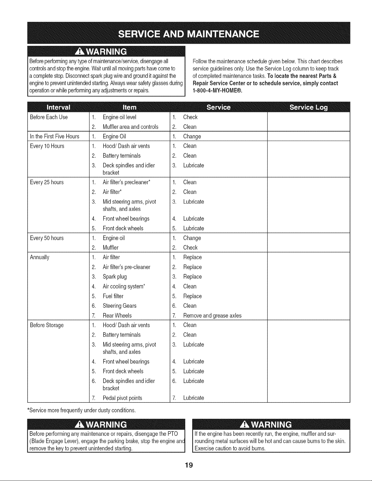
Followthe maintenanceschedulegivenbelow.This chart describes
serviceguidelinesonly.Usethe Service Logcolumnto keeptrack
of completedmaintenancetasks.To locate the nearest Parts &
Repair Service Centeror to scheduleservice,simplycontact
1-800-4-MY-HOME®.
BeforeEachUse
In the First FiveHours
Every10Hours
Every25 hours
Every50 hours
Annually
BeforeStorage
1. Engineoil level
2. Mufflerarea and controls
1. EngineOil
1. Hood/Dash air vents
2. Batteryterminals
3. Deckspindlesandidler
bracket
1. Air filter'sprecleaner*
2. Air filter*
3. Mid steeringarms,pivot
shafts,andaxles
4. Frontwheelbearings
5. Frontdeck wheels
1. Engineoil
2. Muffler
1. Air filter
2. Air filter'spre-cleaner
3. Sparkplug
4. Air coolingsystem*
5. Fuelfilter
6. SteeringGears
7. RearWheels
1. Hood/Dash air vents
2. Batteryterminals
3. Mid steeringarms,pivot
shafts,andaxles
4. Frontwheelbearings
5. Frontdeck wheels
6. Deckspindlesandidler
bracket
7. Pedalpivot points
1. Check
2. Clean
1. Change
1. Clean
2. Clean
3. Lubricate
1. Clean
2. Clean
3. Lubricate
4. Lubricate
5. Lubricate
1. Change
2. Check
1. Replace
2. Replace
3. Replace
4. Clean
5. Replace
6. Clean
7. Removeand greaseaxles
1. Clean
2. Clean
3. Lubricate
4. Lubricate
5. Lubricate
6. Lubricate
7. Lubricate
*Servicemorefrequentlyunderdustyconditions.
(BladeEngageLever),engagethe parkingbrake,stop the engine
removethe key to preventunintendedstarting.
If the enginehasbeenrecentlyrun,theengine,mufflerand sur-
roundingmetalsurfaceswill behotandcan causeburnsto the skin.
Exercisecautionto avoidburns.
19
NOTE: Referencesto the rightor left sideof tractorarefrom the
viewpointof theoperatorfacing forwardfromthe tractorseat.
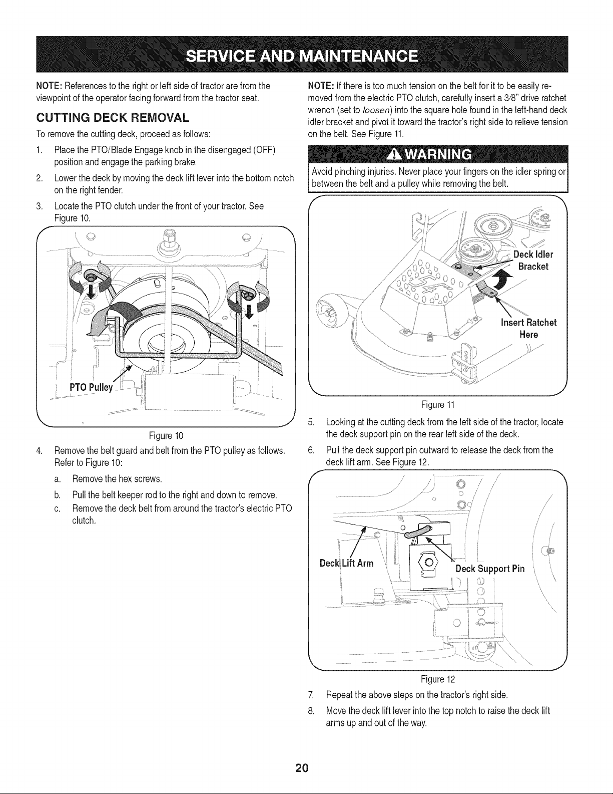
CUTTING DECK REMOVAL
To removethecuttingdeck, proceedas follows:
1. Placethe PTO/BladeEngageknobinthe disengaged(OFF)
positionandengagethe parkingbrake.
2. Lowerthe deckby movingthe deck liftleverintothe bottomnotch
onthe rightfender.
3. Locatethe PTOclutchunderthe frontof yourtractor.See
Figure10.
.
PTO Pulle_
L .................
J
Figure10
Removethe beltguardand beltfromthe PTOpulleyas follows.
Referto Figure10:
a. Removethe hexscrews.
b. Pull the beltkeeperrod to the rightand downto remove.
c. Removethe deck belt from aroundthe tractor'selectricPTO
clutch.
NOTE: If there is too muchtensionon thebelt for it to be easilyre-
movedfromtheelectric PTOclutch,cardully inserta 3/8" driveratchet
wrench(setto loosen) intothe squareholefound inthe Idt-hand deck
idlerbracketand pivotit towardthe tractor'srightsideto relievetension
on the belt. See Figure11.
Avoidpinchinginjuries.Neverplaceyourfingerson the idlerspringor
betweenthe beltanda pulleywhileremovingthe belt.
DeckIdler
Bracket
Insert Ratchet
Here
Figure11
.
Lookingat thecuttingdeckfromthe leftside of thetractor,locate
the deck supportpinon the rear left sideof thedeck.
Pullthe deck supportpinoutwardto releasethe deckfrom the
/
J
/
i
i
Deck Lift Arm
DeckSupportPin
'xx
'x
.
8.
Figure12
Repeatthe abovestepson the tractor'srightside.
Movethedeck lift leverintothe top notchto raisethedeck lift
armsupandout of the way.
20

9. Removethebowtiecotterpinconnectingthedeck swayrodto the
tractorframe.See Figure13.
Rod
Figure13
10. Gentlyslidethe cuttingdecktowardthefrontof the tractor,
carefullyguidingthe hookson the deckoff of thedeck stabilizer
rod.See Figure14.
i ........................
i
' i
i \
/
J
Figure14
11. Gentlyslidethe cuttingdeck(fromthe rightside)out from
underneaththe tractor.
CHANGING THE TRANSMISSION DRIVE
BELT
Severalcomponentsmustbe removedand specialtoolsusedin order
to changethe tractor'stransmissiondrivebelt. Seea Searsor other
qualifiedservicedealerto havethe transmissiondrivebelt replaced.
CHANGING THE DECK BELT
Shutthe engineoff andremoveignitionkeybeforeremovingthe
cuttingblade(s)for sharpeningor replacement.Protectyourhands
usingheavygloveswhengraspingbladesand pulleys.
TheV-belts foundon yourtractorarespeciallydesignedto engage
anddisengagesafely.A substitute(non-OEM)Vibeltcan bedanger-
ous by notdisengagingcompletely.Fora properworkingmachine,
use factoryapprovedbeltsas listedin the PartsListof thismanual..
All beltsonyourtractorare subjectto wearand shouldbereplacedif
any signsof wear are present. Tochangeor replacethe deck belton
yourtractor,proceedas follows:
1. Removethe deckas instructedin the CuttingDecksection.
2. Removethe beltcoversfromtheouter spindlesby removingthe
hexwasherscrewsthat fastenthem to the deck.See Figure15.
f
_ler
Belt KeeperZ
Rod
HexWasher [
Screw
.J
Figure15
Loosen,but do not removethe belt keeperrodon the deckidler
pulleylocatednearthe backof the deck. SeeFigure15.
4. Removethe deckbeltfrom aroundthe threespindlepulleysand
the two deckidlerpulleys.
NOTE:Theidlerpulleysmayhaveto be loosened,butnot removed,in
orderto removethebelt from aroundthem.
21
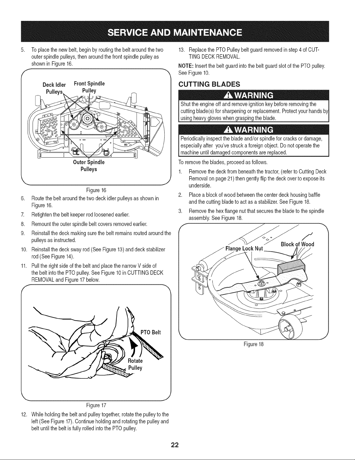
5. Toplacethe newbelt, beginby routingthe belt aroundthe two
outerspindlepulleys,then aroundthefront spindlepulleyas
shownin Figure16.
F
Z
8.
9.
10.
f
11.
Deck idler FrontSpindle
Pulley
Outer Spindle
Pulleys
J
Figure16
Routethe beltaroundthe twodeckidlerpulleysas shownin
Figure16.
Retightenthe belt keeperrodloosenedearlier.
Remounttheouter spindlebeltcoversremovedearlier.
Reinstallthe deck makingsurethe beltremainsroutedaroundthe
pulleysas instructed.
Reinstallthe deck swayrod(See Figure13)and deckstabilizer
rod(SeeFigure14).
Pullthe rightside ofthe beltand placethe narrowV side of
the belt intothe PTOpulley.See Figure10in CUTTINGDECK
REMOVALandFigure17below.
PTO Belt
13. Replacethe PTOPulleybelt guardremovedinstep4 of CUT-
TING DECKREMOVAL.
NOTE: Insertthe beltguardintothe beltguardslotof the PTOpulley.
See Figure10.
CUTTING BLADES
Shutthe engineoff andremoveignitionkeybeforeremovingthe
cuttingblade(s)for sharpeningor replacement.Protectyourhands
usingheavy gloveswhengraspingthe blade.
Periodicallyinspectthe bladeand/orspindlefor cracksor damage,
especiallyafter you'vestrucka foreignobject.Do notoperatethe
machineuntildamagedcomponentsare replaced.
To removethe blades,proceedas follows.
1. Removethe deckfrombeneaththe tractor,(referto CuttingDeck
Removalon page21)thengently flipthe deckoverto exposeits
underside.
2. Placea blockof woodbetweenthe centerdeckhousingbaffle
andthe cuttingbladeto actas a stabilizer.See Figure18.
3. Removethe hexflangenut thatsecuresthe bladeto the spindle
assembly.SeeFigure18.
e LockNut
f
Block
Figure18
... J
Figure17
12. Whileholdingthe beltandpulleytogether,rotatethepulleyto the
left(See Figure17).Continueholdingand rotatingthe pulleyand
belt untilthe beltis fully rolledinto the PTOpulley.
22
4. Jump Starting
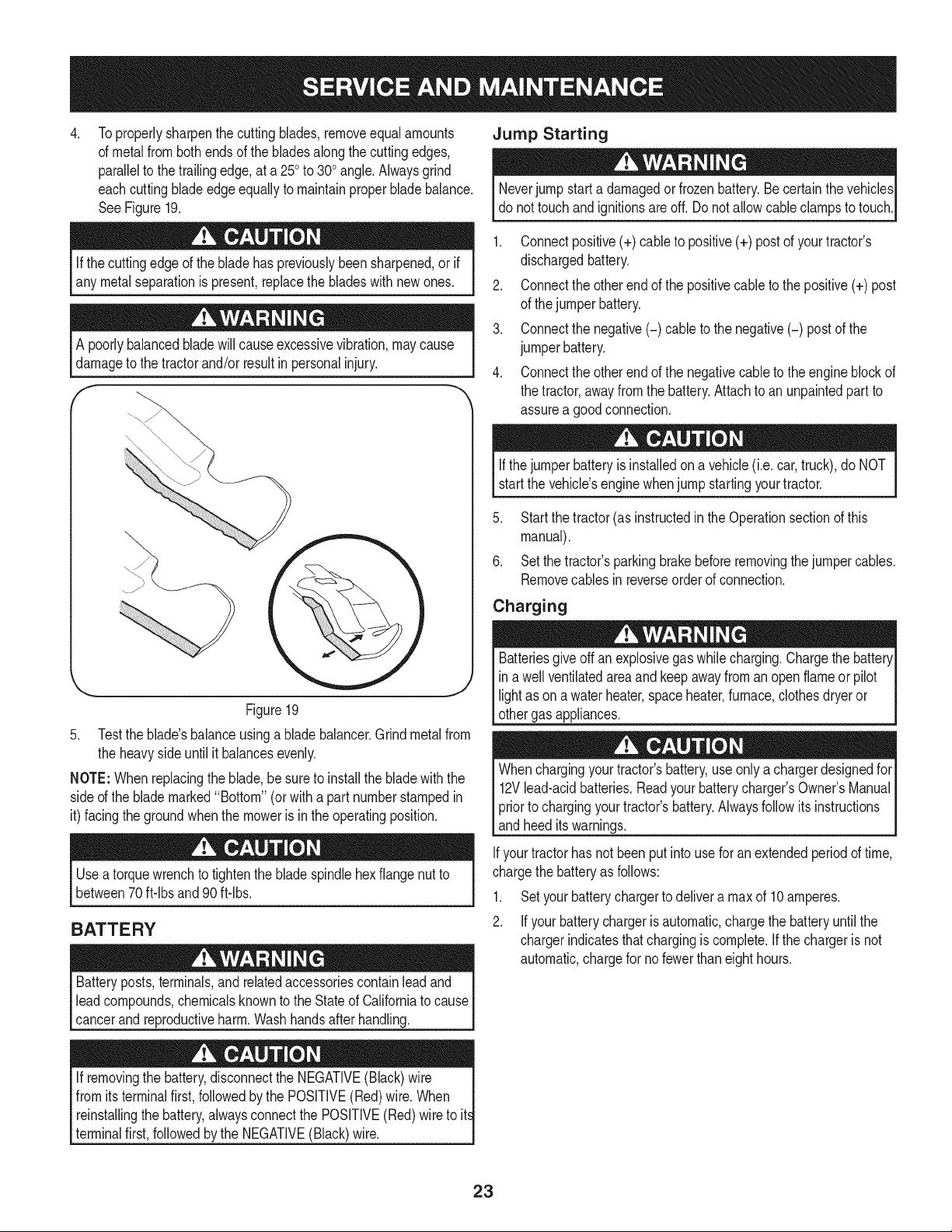
Toproperlysharpenthe cuttingblades,removeequal amounts
of metalfrom both endsof the bladesalongthe cuttingedges,
parallelto thetrailingedge,at a 250to 300angle.Alwaysgrind
eachcuttingbladeedgeequallyto maintainproper bladebalance.
SeeFigure19.
Neverjump starta damagedor frozenbattery.Be certainthe vehicles
do nottouch and ignitionsare off. Donot allowcableclampsto touch.
Ifthe cuttingedgeof the bladehas previouslybeensharpened,orif
any metal separationis present,replacethe bladeswith newones.
A poorlybalancedbladewillcauseexcessivevibration,may cause
damageto the tractorand/or resultinpersonalinjury.
f
\
Figure19
5. Testthe blade'sbalanceusinga bladebalancer.Grind metalfrom
the heavyside untilit balancesevenly.
NOTE:Whenreplacingthe blade,besureto install the bladewith the
sided the blademarked"Bottom" (or witha part numberstampedin
it) facingthe groundwhenthe moweris in the operatingposition.
Useatorquewrenchto tightenthe bladespindlehexflange nutto
between70ft-lbs and90ft-lbs.
BATTERY
Batteryposts,terminals,and relatedaccessoriescontainleadand
leadcompounds,chemicalsknownto the Stateof Californiato cause
cancerandreproductiveharm.Washhandsafterhandling.
If removingthe battery,disconnectthe NEGATIVE(Black)wire |
from itsterminalfirst,followedby the POSITIVE(Red)wire.When
t
reinstallingthe battery,alwaysconnectthe POSITIVE(Red)wire to it
terminalfirst,followedbythe NEGATIVE(Black)wire.
1. Connectpositive(+) cableto positive(+) postof your tractor's
dischargedbattery.
2. Connectthe otherend of the positivecableto the positive(+) post
of the jumperbattery.
3. Connectthe negative(-) cable to the negative(-) postof the
jumperbattery.
4. Connectthe otherend of the negativecableto the engineblock of
the tractor,awayfromthe battery.Attachto anunpaintedpartto
assurea goodconnection.
Ifthejumperbatteryis installedona vehicle(i.e. car,truck),do NOT
start the vehicle'senginewhenjump startingyourtractor.
5. Startthe tractor(as instructedin theOperationsectionof this
manual).
6. Setthe tractor'sparkingbrakebeforeremovingthejumpercables.
Removecablesinreverseorderof connection.
Charging
Batteriesgiveoff an explosivegas whilecharging.Chargethe battery[
in a wellventilatedareaand keepawayfroman openflame or pilot [
lightas on a waterheater,spaceheater,furnace,clothesdryeror [
othergas appliances. ..J
Whenchargingyourtractor'sbattery,use onlya chargerdesignedfor
12Vlead-acidbatteries.Readyourbatterycharger'sOwner'sManual
priorto chargingyourtractor'sbattery.Alwaysfollowitsinstructions
andheeditswarnings.
Ifyourtractorhas notbeenput intouse for an extendedperiodof time,
chargethe batteryas follows:
1. Setyourbatterychargerto delivera max of 10amperes.
2. Ifyour batterychargeris automatic,chargethe batteryuntilthe
chargerindicatesthatchargingis complete.If thechargeris not
automatic,chargefor nofewerthaneighthours.
23
FUSE
Beforeservicing,repairing,or inspecting,alwaysdisengagePTO
(BladeEngageknob),setparkingbrake,stopengineand remove
to preventunintendedstarting.
Afuse isinstalledin yourtractor'swiringharnessto protectthe trac-
tor'selectricalsystemfrom damagecausedbyexcessiveamperage.
Ifthe electricalsystemdoesnot function,or yourtractor'senginewill
notcrank,first checkto becertainthatthe fusehasnot blown.It is
locatedunderthe hood,mountedbehindthe top of the dashpanelon
the supportbar.
Alwaysusea replacementfuse withthe sameamperagecapacity as
the blownfuse.
TIRES
Neverexceedthe maximuminflationpressureshownon the sidewall
of thetire.
Referto the tire sidewallfor exacttire manufacturer'srecommendedor
maximumpsi. Donot overinfiate.Uneventire pressurecouldcause the
cuttingdeck to mowunevenly.
MAINTENANCE
Beforeperformingany maintenanceor repairs,disengagePTO,set
parkingbrake,stopengineand removekeyto preventunintended
starting.
CLEANING THE TRACTOR
Anyfuel oroil spilledon the machineshouldbewipedoff promptly.Do
NOTallowdebristo accumulatearoundthe coolingfinsof the engine,
thetransmission'scoolingfan or on any otherpartof the machine,
especiallythe beltsand pulleys.
Deck Wash System
Yourtractor'sdeckis equippedwithawaterport onitssurfaceas part
of itsdeck washsystem.
Usethedeck washsystemto rinsegrass clippingsfromthe deck's
undersideandpreventthe buildupof corrosivechemicals.Complete
thefollowingstepsAFTEREACHMOWING:
1. Drivethe tractorto a level,clearspot on your lawn,near enough
for yourgardenhoseto reach.
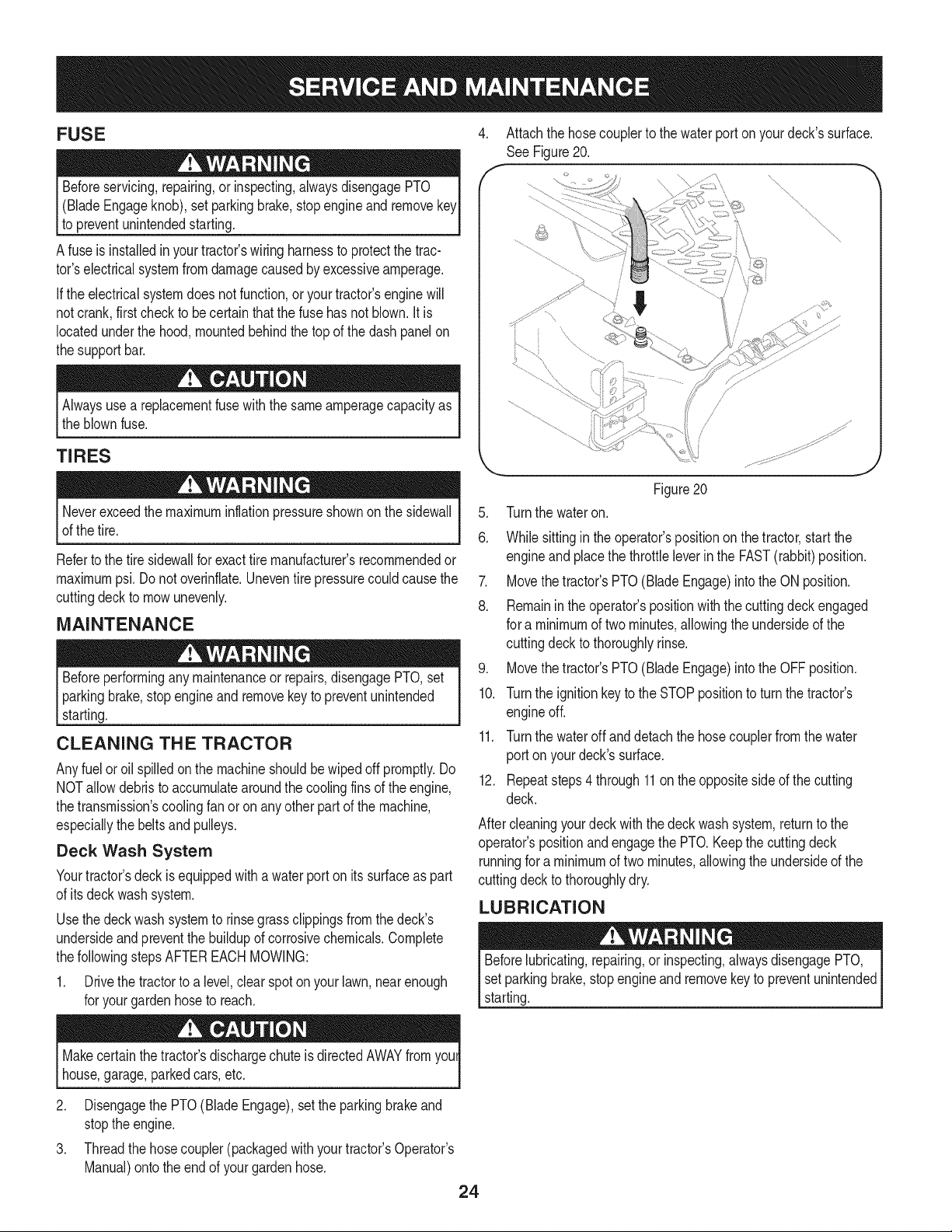
4. Attachthe hosecouplerto thewater porton yourdeck'ssurface.
See Figure 20.
\,
"\,
............. j
.
6.
Figure20
Turnthe wateron.
Whilesittingin the operator'spositionon the tractor,start the
engineand placethe throttleleverin the FAST(rabbit)position.
7. Movethetractor'sPTO(BladeEngage)intothe ON position.
8. Remainin theoperator'spositionwith the cuttingdeck engaged
for a minimumof twominutes,allowingthe undersideof the
cuttingdeck to thoroughlyrinse.
9. Movethetractor'sPTO(BladeEngage)intothe OFFposition.
10. Turnthe ignitionkeyto the STOPpositionto turn the tractor's
engineoff.
11. Turnthe wateroffanddetach the hosecouplerfrom thewater
port on yourdeck'ssurface.
12. Repeatsteps4 through11on the oppositesideof the cutting
deck.
Aftercleaningyourdeck withthe deck washsystem,returnto the
operator'spositionandengagethe PTO.Keepthe cuttingdeck
runningfor a minimumof twominutes,allowingthe undersideof the
cuttingdeck to thoroughlydry.
LUBRICATION
Beforelubricating,repairing,orinspecting,alwaysdisengagePTO,
setparkingbrake,stopengine and removekey to preventunintended
starting.
Makecertainthe tractor'sdischargechute isdirectedAWAYfrom youl
house,garage,parkedcars,etc.
2. Disengagethe PTO(Blade Engage),setthe parkingbrakeand
stoptheengine.
3. Threadthe hosecoupler(packagedwithyourtractor'sOperator's
Manual)ontothe endof your gardenhose.
24

Front Wheels
Eachof the front wheelaxles and rimsisequippedwitha grease
fitting.SeeFigure21.Lubricatewitha No.2 multi-purposegrease
appliedwitha greasegunafterevery25 hoursof tractoroperation.
f -,
//
_7
/
/
/
/
/
i
i
J
Ji
i
!
//
/i
z /
/i
/?/
Figure21
Pivot Points & Linkage
Lubricateall the pivotpointson thedrive system,parkingbrakeand lift
linkageat leastoncea seasonwith lightoil.
Deck Wheels
Eachof the tractordeck'sfrontgaugewheelsisequippedwith a
greasefitting.Lubricatewitha No.2 multi-purposegreaseappliedwith
a greasegunafterevery25 hoursof tractoroperation.
Deck Spindle
Greasefittingscanbe foundon eachdeckspindle.See Figure22.
Lubricatewith251HEPgreaseor an equivalentNo.2 multi-purpose
lithiumgrease.Usinga greasegun, applytwo strokes(minimum)or
sufficientgreaseto the spindleshaft.
Figure22
ADJUSTMENTS
Shutthe engineoff, removethe ignitionkey and engagethe parking
brakebeforemakingadjustments.Protectyourhandsby usingheavy
gloveswhenhandlingthe blades.
NOTE:Checkthe tractor'stire pressurebeforeperformingany deck
levelingadjustments.Referto Tireson page28 for informationregard-
ingtirepressure.
Leveling the Deck (Front To Rear)
The front of thecuttingdeck is supportedby a stabilizerbar that can
beadjustedto levelthe deckfromfrontto rear.The frontof thedeck
shouldbe between1/4-inchand3/8-inch lowerthan the rearof the
deck.Adjust if necessaryas follows:
1. Parkthe tractorparkedon a firm, levelsurfaceand placethe deck
liftleverin thetop notch.
2. Rotatethe bladenearestthe dischargecoverchutesothat it is
parallelwiththe tractor.
3. Measurethedistancefromthe frontof the bladetip to theground
andthe rearof the bladetip tothe ground.Thefirst measurement
takenshouldbe between1/4-inchand3/8-inchless thanthe
secondmeasurement.
Determinetheapproximatedistancenecessaryfor properadjustment
and proceed,ifnecessary.
1. Loosen(threadoutward)the hexlock nut onthe endof the deck
hangerrod.See Figure23.
/
/
J
i
/
Figure23
2. To raise the frontof the deck,tighten(threadinward)the inner
hexnutagainstthe fronthangerbracket.
3. To Iowerthe frontof the deck,loosen(threadoutward)the hex
nut,awayfromthe front hangerbracket.See Figure23.
4. Retightenthe locknutagainstthe hex nutwhenproperadjust-
mentis achieved.
25
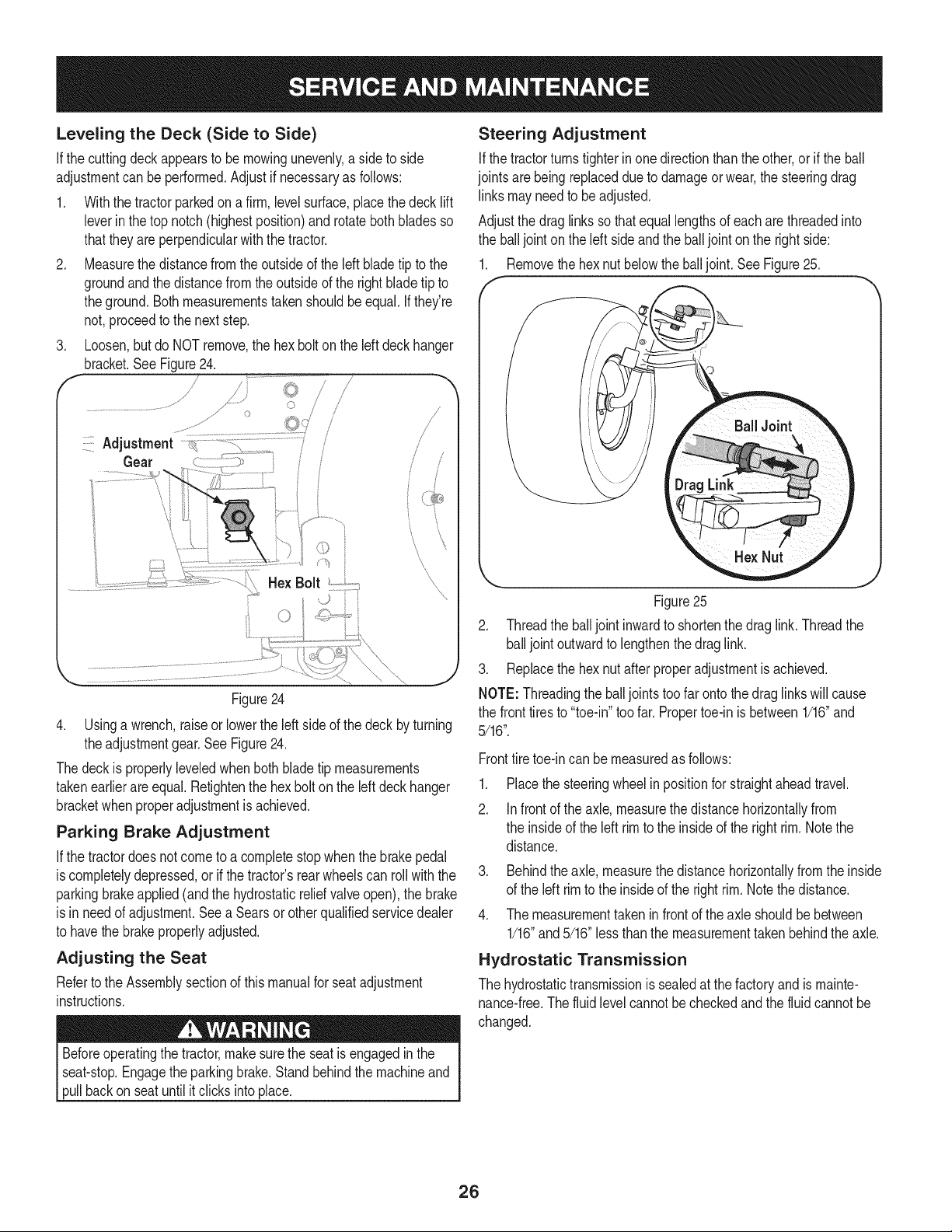
Leveling the Deck (Side to Side)
Ifthe cuttingdeckappearsto bemowingunevenly,a side to side
adjustmentcan be performed.Adjustif necessaryas follows:
1. Withthe tractorparkedon a firm,levelsurface,placethe decklift
leverinthe top notch(highestposition)and rotatebothbladesso
thattheyareperpendicularwiththe tractor.
2. Measurethe distancefromthe outsideof the leftbladetip to the
groundandthe distancefrom theoutsideof the rightbladetip to
theground.Bothmeasurementstakenshouldbeequal. Ifthey're
not,proceedto the nextstep.
3. Loosen,butdo NOTremove,the hexbolt onthe left deckhanger
bracket.See Figure24.
/
J
/ S
J
Figure24
4. Usinga wrench,raiseor lowerthe left sideof thedeck byturning
theadjustmentgear.SeeFigure24.
Thedeck is properlyleveledwhenbothbladetip measurements
takenearlierareequal. Retightenthe hexbolton the leftdeckhanger
bracketwhenproperadjustmentis achieved.
Parking Brake Adjustment
Ifthe tractordoesnot cometo a completestopwhenthe brakepedal
iscompletelydepressed,or ifthe tractor'srearwheelscan rollwith the
parkingbrakeapplied(and the hydrostaticreliefvalveopen),the brake
is in needof adjustment.Seea Searsor otherqualifiedservicedealer
to havethe brakeproperlyadjusted.
Adjusting the Seat
Referto the Assemblysectionof thismanualfor seatadjustment
instructions.
Beforeoperatingthe tractor,makesurethe seatis engagedin the
seat-stop.Engagethe parkingbrake.Standbehindthe machineand
pullbackon seatuntilitclicks intoplace.
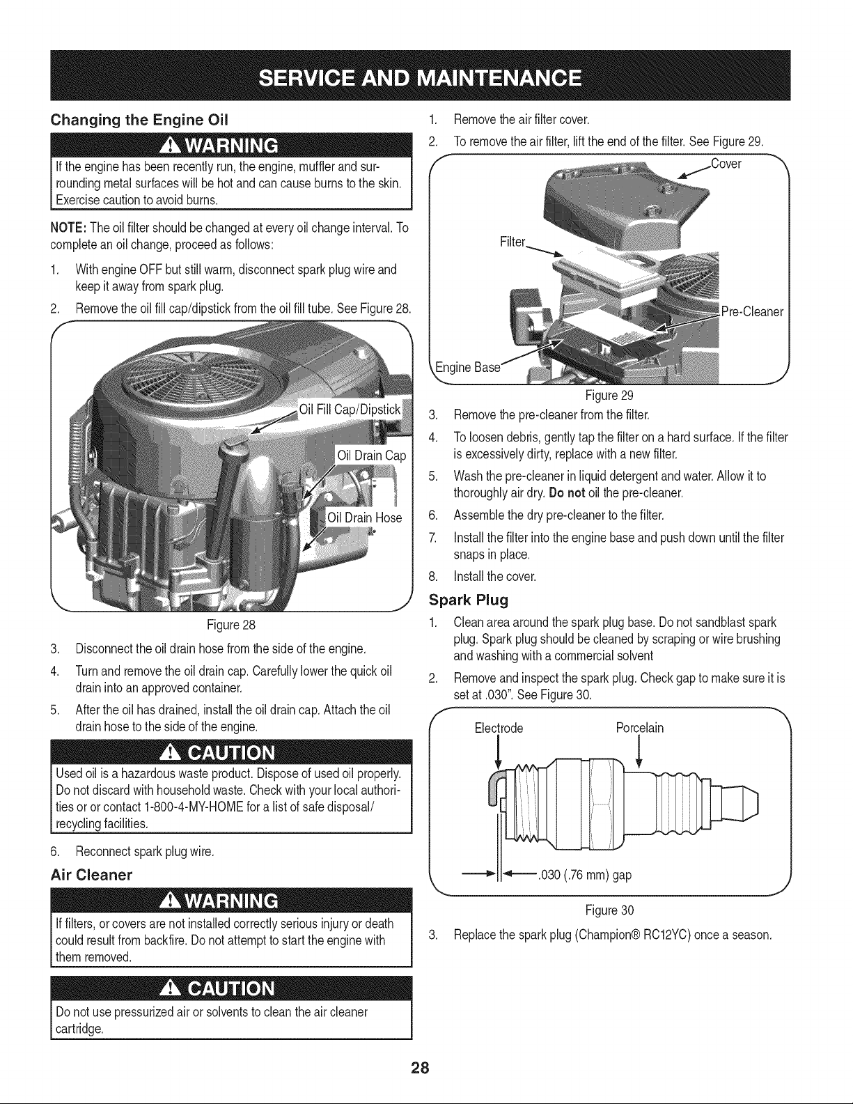
Steering Adjustment
Ifthe tractorturnstighterinone directionthanthe other,or if the ball
jointsarebeing replaceddue to damageorwear,the steeringdrag
linksmayneedto beadjusted.
Adjustthe drag links so that equallengthsof each are threadedinto
the ball jointon the left sideandthe balljointon the rightside:
1. Removethe hexnut belowthe balljoint.SeeFigure25.
Figure25
2. Threadthe balljointinwardto shortenthe drag link.Threadthe
balljoint outwardto lengthenthedrag link.
3. Replacethe hexnut afterproperadjustmentis achieved.
NOTE: Threadingthe balljointstoofar ontothe draglinkswillcause
the front tiresto "toe-in"toofar. Propertoe-in is between1/16"and
5/16".
Fronttiretoe-incan be measuredas follows:
.
2.
Placethe steeringwheelinpositionfor straightaheadtravel.
Infront of the axle,measurethe distancehorizontallyfrom
the insideof the left rimto the insideof the right rim.Notethe
distance.
3. Behindthe axle,measurethe distancehorizontallyfromthe inside
of the left rimto the insideof the rightrim. Notethe distance.
4. The measurementtaken in frontof the axle shouldbebetween
1/16"and5/16"lessthanthe measurementtakenbehindthe axle.
Hydrostatic Transmission
The hydrostatictransmissionis sealedat thefactoryandis mainte-
nance-free.The fluidlevelcannotbecheckedand the fluidcannot be
changed.
26

DECK REAR ROLLER ADJUSTMENT
The rear rollerson the mowerdeckare not designedto carry the
weightof the deck.The rearrollersshouldbe adjustedto approxi-
mately1/4"to 1/2"abovethe groundwhenthe deckis movedto the
desiredcuttingheight.
Placethetractoron a smooth,fiat surface,movethe deck to the
desiredcuttingheight,and checkthe heightof the rear rollers.If
contactingthe ground,or above 1/2"fromthe ground,adjust the rear
rollersas follows:
Thedeck rollerassemblyindexbrackethasfive adjustmentpositions
holes.
f
Whilesupportingthe rollerassembly,removeclick pin and
withdrawtheclevis pinfromboththe left andright rollerindex
brackets.SeeFigure26.
indexBracket
Figure26
2. Positionthe rollerassemblyso thatthe rollersare approximately
1/4"to 1/2"abovetheflat surfacebelow.
3. Align thenearestindexbracketholeswith the holesin the deck
mountingbrackets.Insertthe clevispinsthroughthe deck
bracketsandthe indexbracketsand securewiththe click pins.
SeeFigure26.
NOTE:The clevispinsshouldbe in the correspondingholesof both
the left and rightrollerindexbrackets.
ENGINE MAINTENANCE
Checking the Engine Oil
Onlyusehighquality detergentoil ratedwithAPI serviceclassification
SF,SG, SH, orSJ. Selectthe oil'sSAEviscositygradeaccordingto
the expectedoperatingtemperature.Followthe chart below.
"Colder _'_ 32°F ="-Warmer_
Oil Viscosity Chart
Althoughmulti-viscosityoils (5W20, 10W30,etc.) improvestarting
incoldweather,they will resultinincreasedoilconsumptionwhen
usedabove32°E Checkyourengineoil levelmorefrequentlyto avoid
possibleenginedamagefrom runninglow on oil.
Tocheckthe engineoil, proceedas follows:
1. Ensurethat the tractoris on a levelsurface.
2. Cleanthe oilfill area of any debris.
3. Removethe dipstickandwipewith a cleancloth.
4. Insertandtighten dipstick.
5. Removethe dipstickandcheckthe oillevel.It shouldbe at the
Fullmarkon the dipstick.SeeFigure27.
Figure27
Iflow,addoil slowlyintotheengineoil fill. Donot overfill.After
addingoil, wait oneminuteandthen recheckthe oillevel.
Do notoverfill.Overfillingwithoil may causethe engineto not start,
hardstarting,or enginesmoking.Ifoverthe FULLmarkonthe
dipstick,drain oil to reduceoil levelto FULLmarkon dipstick.
7. Replaceand tightendipstick.
27
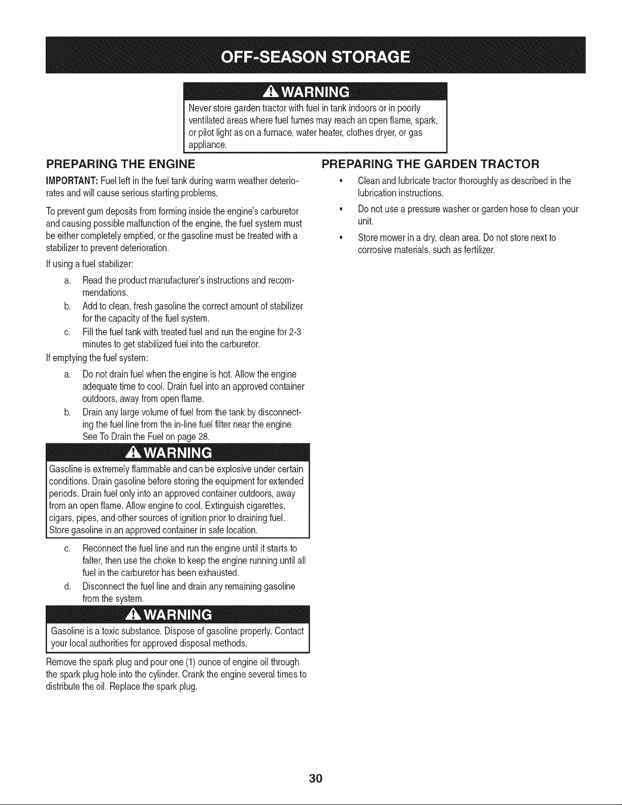
Changing the Engine Oil
Ifthe enginehasbeenrecentlyrun,the engine,mufflerand sur-
roundingmetalsurfaceswill be hotandcan causeburnsto the skin.
Exercisecautionto avoidburns.
,
2.
Removethe airfiltercover.
To removethe airfilter,liftthe endof thefilter.SeeFigure29.
/Cover
NOTE:The oilfiltershouldbechangedat everyoilchangeinterval.To
completeanoil change,proceedas follows:
1. Withengine OFF butstillwarm,disconnectsparkplugwire and
keepit awayfromsparkplug.
2. Removethe oil fill cap/dipstickfromthe oilfill tube.See Figure28.
Figure28
[Pre-Cleaner
3. Disconnectthe oildrain hosefromthe sideof theengine.
4. Turnand removethe oildraincap.Carefullylowerthe quickoil
drainintoan approvedcontainer.
5. Afterthe oil has drained,installthe oildraincap. Attachtheoil
drainhoseto the sideof the engine.
Usedoil is a hazardouswasteproduct.Disposeof usedoil properly.
Do notdiscardwith householdwaste.Checkwith your localauthori-
tiesoror contact1-800-4-MY-HOMEfora listof safedisposal/
recyclingfacilities.
6. Reconnectspark plugwire.
Air Cleaner
Iffilters,orcoversarenot installedcorrectlyseriousinjuryor death
couldresultfrom backfire.Do notattemptto start theenginewith
themremoved.
_J
Figure29
3. Removethe pre-cleanerfromthe filter.
4. To loosendebris,gentlytapthe filteron a hardsurface.If thefilter
is excessivelydirty,replacewith a newfilter.
5. Washthe pre-cleanerinliquiddetergentandwater.Allowit to
thoroughlyair dry.Do not oilthe pre-cleaner.
6. Assemblethe dry pre-cleanerto the filter.
7. Installthe filterintothe enginebaseand pushdown untilthe filter
snapsin place.
8. Installthe cover.
Spark Plug
1. Cleanarea aroundthe sparkplugbase.Donot sandblastspark
plug. Sparkplugshouldbecleanedby scrapingor wirebrushing
andwashingwitha commercialsolvent
Removeandinspectthe sparkplug.Checkgapto makesureit is
setat .030".SeeFigure30.
Electrode Porcelain
_ _'_.030 (.76 ram) gap
Figure 30
3. Replace the spark plug (Champion® RC12YC)once a season.
Do notuse pressurizedair or solventsto cleanthe aircleaner
cartridge.
28

Fuel Filter Muffler
Gasolineanditsvaporsareextremelyflammableand explosive.Fire
or explosioncan cause severeburnsor death.
• Keepgasolineawayfrom sparks,open flames,pilotlights,heat,
andotherignitionsources.
• Checkfuellines,tank,cap, andfittingsfrequentlyfor cracks
orleaks.Replaceif necessary.Seea Searsor other qualified
servicedealerto replacefuel line.
• Beforereplacingthe fuel filter,drain the fueltank or closethe fuel
shut-offvalve.
• Replacementpartsmustbe the same and installedin the same
positionas the originalparts.
• If fuelspills,waituntil it evaporatesbeforestartingengine.
To Drainthe Fuel:
1. Locatethefuel filter,whichis routedon the left sideof theengine
betweenthe fuel tankandthe carburetor,andmay be attachedto
the enginewith a tie strap.
2. Cut the tie strap,if present,thenpinchthe in-lineclampon the
fuelfilter with a pairof pliers.
3. Slide theclamp up the fuel line.
4. Pull thefuel linefree fromthe filterandplacethe openendof the
lineintoan approvedcontainerto drainthe fuel.
To Replacethe FuelFilter:
1. Beforereplacingthe fuel filter,drain the fueltank or closethe fuel
shut-offvalve.Otherwise,fuel can leakout andcausea fire or
explosion.
2. Use pliersto squeezetabson theclamps,then slidethe clamps
awayfromthefuel filter.Twistand pull thefuel linesoff of the fuel
filter.See Figure31.
f --,
Clamp
FuelLine
/
_ J
Figure31
3. Checkthefuel linesfor cracksor leaks.Replaceif necessary.
4. Replacethefuel filterwithanoriginalequipmentreplacement
filter.
5. Securethe fuel lineswith the clamps.
Temperatureof mufflerand nearbyengineareasmay exceed150° F
(65°0).Avoidcontactwiththeseareas.
Inspectmufflerperiodically,andreplaceif necessary.Replacement
partsfor the mufflermustbe the sameandinstalledin the same
positionas the originalparts.
Clean Engine
Donot usewaterto cleanengine parts.Watercouldcontaminatefuel
system.Usea brushor dry cloth.
Dailyor beforeeveryuse,cleangrass,chaff oraccumulated
debrisfrom engine.Keeplinkage,spring,andcontrolsclean.
Keepareaaroundand behindmufflerfree of anycombustible
debris.
Keepingenginecleanallowsair movementaroundengine.
• Engineparts shouldbekept cleanto reducethe riskof overheat-
ingandignitionof accumulateddebris.
Carburetor Adjustment
The carburetoron thisengineis notadjustable.
Battery
Batteryposts,terminals,and relatedaccessoriescontainleadand
leadcompounds,chemicalsknownto the Stateof Californiato cause
cancerand reproductiveharm.Washhandsafter handling.
The batteryis sealedandis maintenance-free.Acidlevelscannot be
checkedandfluid can notbe added.
Alwayskeepthe batterycablesand terminalscleanandfree of
corrosivebuild-up.
Aftercleaningthe batteryand terminals,applya lightcoatof
petroleumjelly orgreaseto bothterminals.
Ifremovingthe batteryforcleaning,disconnectthe NEGATIVE
(Black)wire from itsterminalfirst,followedby the POSITIVE(Red)
wire.Whenreinstallingthe battery,alwaysconnectthe POSITIVE
(Red)wire to its terminalfirst,followedbythe NEGATIVE(Black)
wire.Becertainthatthe wiresareconnectedto the correctterminals;
reversingthemcouldresult in seriousdamageto yourengine's
alternatingsystem.
29
Neverstoregardentractorwith fuel intankindoorsor in poorly
ventilatedareaswherefuel fumesmay reachan openflame,spark,
or pilot lightas ona furnace,waterheater,clothesdryer,or gas
appliance.
PREPARING THE ENGINE
IMPORTANT:Fuelleft inthe fueltankduringwarm weatherdeterio-
ratesandwill causeseriousstartingproblems.
Topreventgum depositsfromforminginsidetheengine'scarburetor
andcausingpossiblemalfunctionof the engine,the fuel systemmust
beeithercompletelyemptied,or thegasolinemustbe treatedwith a
stabilizerto preventdeterioration.
If usinga fuel stabilizer:
a. Readthe productmanufacturer'sinstructionsand recom-
mendations.
b. Add to clean,freshgasolinethe correctamountof stabilizer
for thecapacityof the fuel system.
c. Fill thefuel tankwithtreatedfueland runtheenginefor 2-3
minutesto get stabilizedfuel intothe carburetor.
If emptyingthefuel system:
a. Do notdrain fuel whentheengineis hot.Allowtheengine
adequatetimeto cool. Drainfuel intoan approvedcontainer
outdoors,awayfromopen flame.
b. Drainany largevolumeof fuelfromthe tankby disconnect-
ingthe fuel linefromthe in-linefuelfilter near theengine.
SeeToDrainthe Fuelon page 28.
Gasolineis extremelyflammableand can be explosiveundercertain
conditions.Draingasolinebeforestoringtheequipmentfor extended
periods.Drainfuelonly intoan approvedcontaineroutdoors,away
fromanopenflame.Allowengineto cool.Extinguishcigarettes,
cigars,pipes,and other sourcesof ignitionprior to drainingfuel.
Storegasolinein an approvedcontainerin safe location.
c. Reconnectthe fuelline and runtheengine untilit startsto
falter,then usethe choketo keepthe engine runninguntilall
fuelin the carburetorhasbeen exhausted.
d. Disconnectthe fuel lineanddrainany remaininggasoline
fromthe system.
PREPARING THE GARDEN TRACTOR
• Cleanand lubricatetractorthoroughlyas describedin the
lubricationinstructions.
• Do notuse a pressurewasheror gardenhoseto cleanyour
unit.
• Storemowerin a dry, cleanarea.Do not storenextto
corrosivematerials,suchas fertilizer.
Gasolineis a toxicsubstance.Disposeof gasolineproperly.Contact
yourlocal authoritiesfor approveddisposal methods.
Removethespark plug andpourone(1)ounceof engineoilthrough
the sparkplug hole intothe cylinder.Crankthe engineseveraltimesto
distributetheoil. Replacethe sparkplug.
30
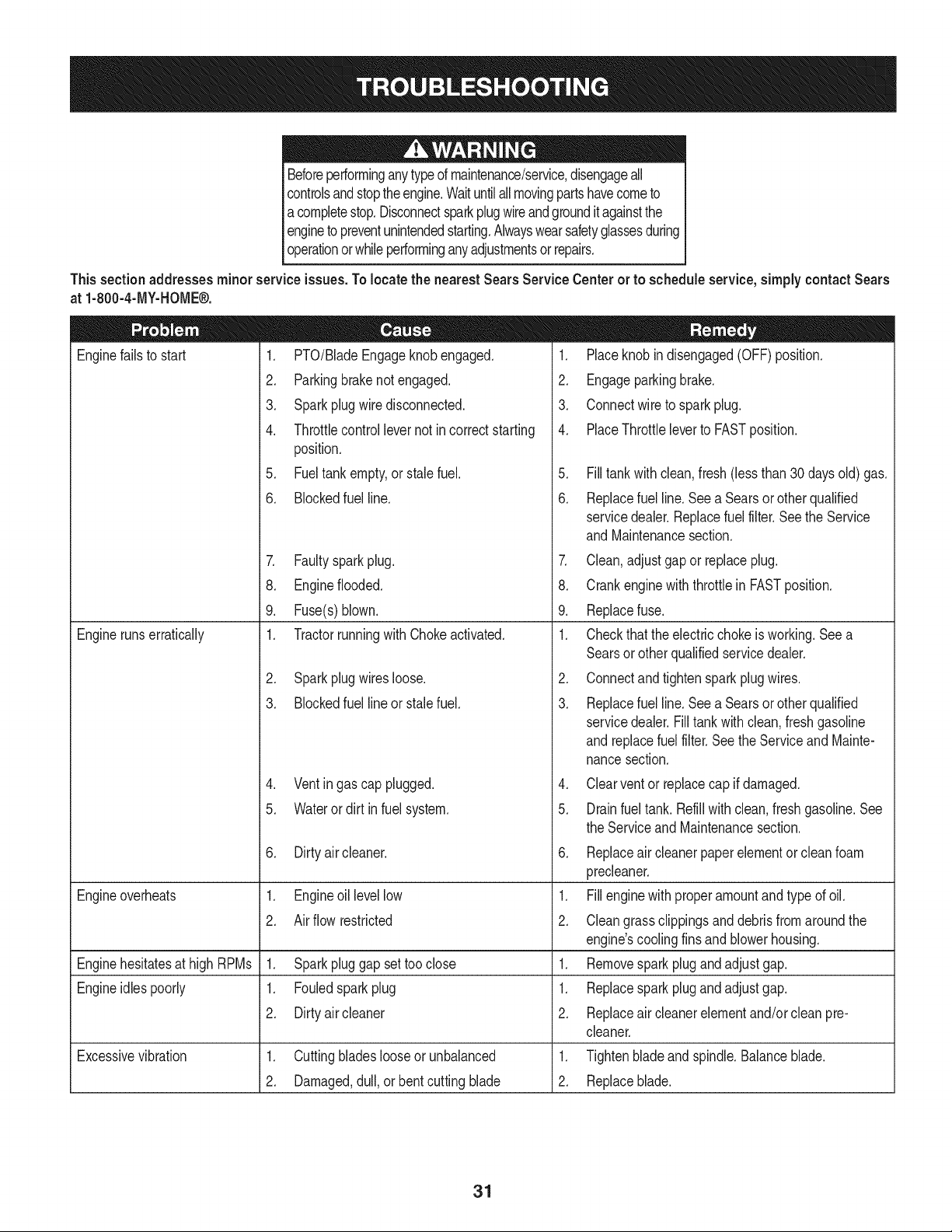
Beforeperforminganytypeof maintenance/service,disengageall
controlsandstoptheengine.Waituntilallmovingpartshavecometo
a completestop.Disconnectsparkplugwireandgroundit againstthe
engineto preventunintendedstarting.Alwayswearsafetyglassesduring
operationorwhileperforminganyadjustmentsorrepairs.
Thissectionaddresses minorserviceissues.To locate the nearestSears Service Centeror to scheduleservice,simplycontactSears
at 1-800-4-MY-HOME®.
1. PTO/BladeEngageknobengaged.
2. Parkingbrakenotengaged.
3. Sparkplugwire disconnected.
4. Throttlecontrollevernot incorrectstarting
position.
5. Fueltankempty,or stale fuel.
Enginefailsto start
6. BIockedfuel line.
7. Faultysparkplug.
8. Engineflooded.
9. Fuse(s)blown.
1. Tractorrunningwith Chokeactivated.
2. Sparkplugwiresloose.
3. Blockedfuel lineor stalefuel.
4. Ventingas cap plugged.
5. Wateror dirt in fuel system.
Dirtyair cleaner.
Enginerunserratically
6. 6.
Engineoverheats 1. Engineoil levellow 1.
2. Air flow restricted 2.
Enginehesitatesat high RPMs 1. Sparkpluggap settooclose 1. Remove
Engineidlespoorly 1. Fouledspark plug 1. Replace
2. Dirtyair cleaner 2. Replace
cleaner.
1. Placeknobin disengaged(OFF)position.
2. Engageparkingbrake.
3. Connectwireto sparkplug.
4. PlaceThrottleleverto FASTposition.
5. Filltankwith clean, fresh(less than 30 days old) gas.
6. Replacefuel line.See a Searsor otherqualified
servicedealer.Replacefuel filter.Seethe Service
andMaintenancesection.
7. Clean,adjustgap or replaceplug.
8. Crankenginewith throttlein FASTposition.
9. Replacefuse.
1. Checkthat the electricchokeis working.Seea
Searsor otherqualifiedservicedealer.
2. Connectand tightenspark plugwires.
3. Replacefuel line.See a Searsor otherqualified
servicedealer.Filltankwith clean,fresh gasoline
andreplacefuel filter.See the Serviceand Mainte-
nancesection.
4. Clearvent or replacecap if damaged.
5. Drainfueltank. Refillwith clean,freshgasoline.See
theServiceand Maintenancesection.
Replaceair cleanerpaperelementor cleanfoam
precleaner.
Fillenginewith properamountand type of oil.
Cleangrassclippingsanddebrisfromaroundthe
engine'scoolingfins andblowerhousing.
sparkplugandadjustgap.
sparkplugandadjustgap.
air cleanerelementand/orcleanpre-
Excessivevibration 1. Cuttingbladeslooseor unbalanced 1. Tightenbladeand spindle.Balanceblade.
2. Damaged,dull,or bentcuttingblade 2. Replaceblade.
31
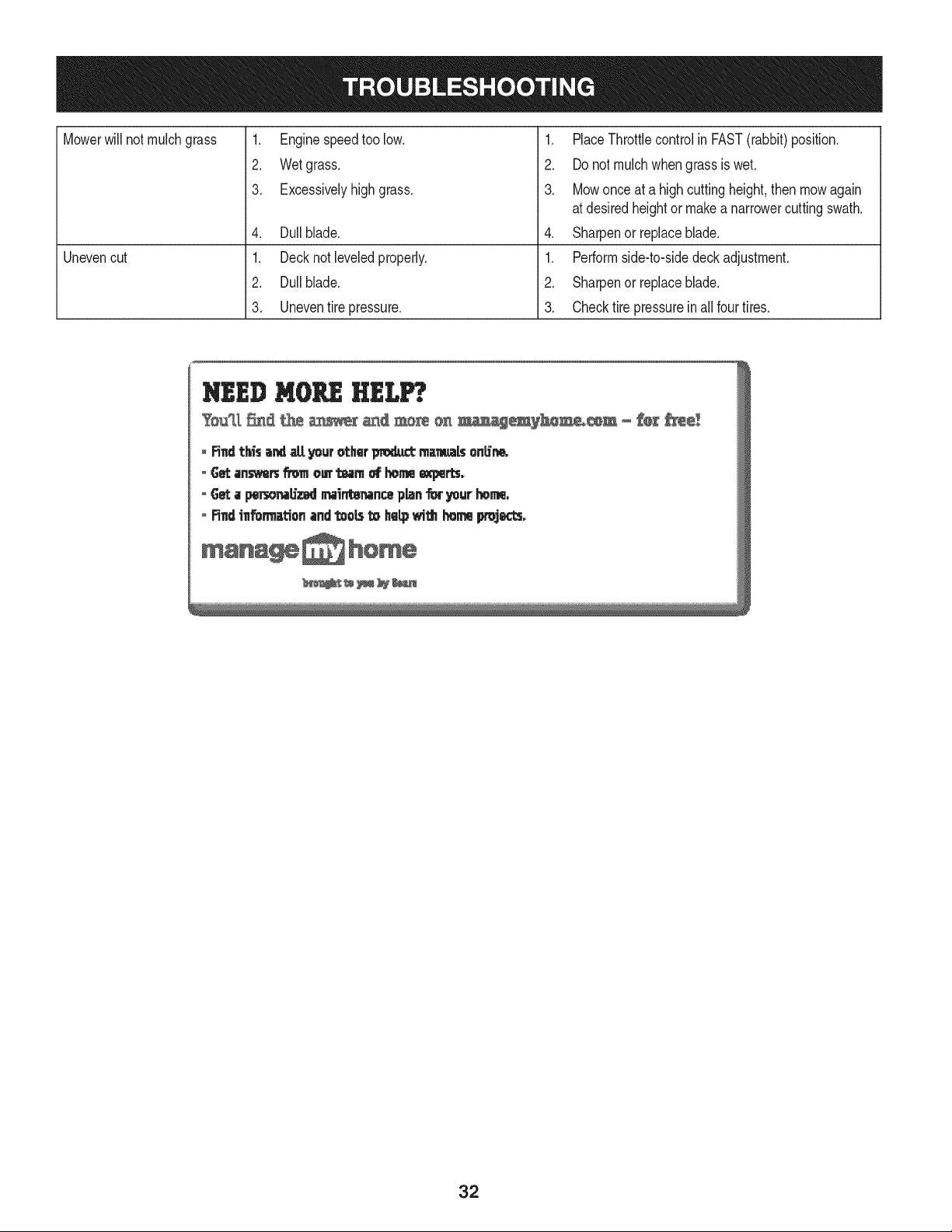
Mowerwill not mulchgrass
Unevencut
1. Enginespeedtoo low.
2. Wetgrass.
3. Excessivelyhighgrass.
4. Dullblade.
1. Decknotleveledproperly.
2. Dullblade.
3. Uneventire pressure.
1. PlaceThrottlecontrolin FAST(rabbit)position.
2. Do notmulch whengrass is wet.
3. Mowonce at a highcuttingheight,then mowagain
at desiredheightor makea narrowercuttingswath.
4. Sharpenor replaceblade.
1. Performside-to-sidedeck adjustment.
2. Sharpenor replaceblade.
3. Checktire pressureinall fourtires.
32

Congratulationson makinga smartpurchase.YournewCraftsman@
productis designedand manufacturedfor yearsof dependableopera-
tion.But likeall products,it mayrequirerepairfromtimeto time.That's
whenhavinga RepairProtectionAgreementcansave youmoneyand
aggravation.
Here'swhatthe RepairProtectionAgreement*includes:
* Expert service byour 10,000professionalrepairspecialists
o Unlimitedserviceand no chargefor partsand laboron all
coveredrepairs
o Product replacementupto $1500if yourcoveredproductcan't be
fixed
• Discountof 10%from regularprice of serviceand relatedinstalled
partsnotcoveredby theagreement;also, 10%off regularpriceof
preventivemaintenancecheck
• Fast help by phone- we call it RapidResolution- phone support
froma Searsrepresentative.Thinkof usas a "talkingowner's
manual."
Onceyou purchasethe Agreement,a simplephonecall is all thatit
takesfor youto scheduleservice.Youcan call anytimedayor night,or
schedulea serviceappointmentonline.
The RepairProtectionAgreementis a risk-freepurchase.If youcancel
for any reasonduringthe productwarrantyperiod,wewill provideafull
refund.Or,a proratedrefundanytimeafter the productwarrantyperiod
expires.Purchaseyour RepairProtectionAgreementtoday!
Somelimitationsand exclusionsapply. For pricesand additional
informationin the U.S.A. call 1-800-827-6655.
*Coverage in Canadavaries on some items. Forfull details call
Sears Canadaat 1-800-361-6665.
Sears Installation Service
ForSearsprofessionalinstallationof homeappliances,garagedoor
openers,waterheaters,and othermajorhomeitems,in the U.S.A.or
Canadacall 1-800-4-MY-HOME®.
33
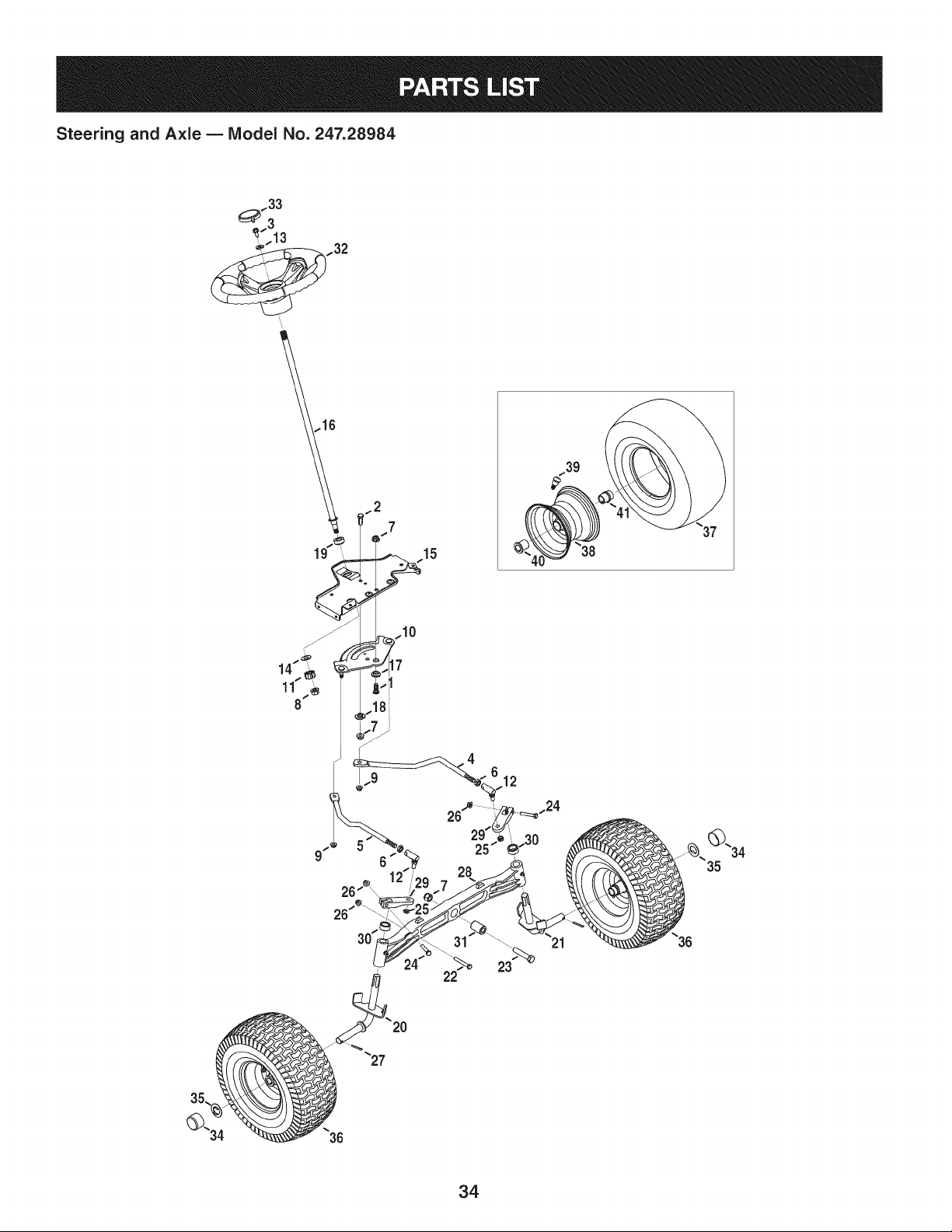
Steering and Axle B IViodel No. 247.28984
..39
10
22
23
34

Steering and Axle B Model No. 247.28984
710-04095 HexHeadScrew,3/8-16:1.00 710-0395 HexHeadScrew,5/16-18:2.25
2 710-0514 HexHeadScrew,3/8-16:1.00 23 710-0859 HexHeadScrew,3/8-16:2.50
3 710-0643 HexHeadScrew,5/16-18:1.00 24 710-3180 HexHeadScrew,5/16-18:1.75
4 711-04998 LH DragLink 25 912-0214 HexlockNut,3/8-24
5 711-04999 RHDragLink 26 712-04063 FlangelockNut,5/16-18
6 912-0240 JamNut,7/16-20 27 714-0162 CotterPin,5/32:1.25
7 712-04065 FlangelockNut,3/8-16 28 719-04413A PivotBarAxle
8 712-0459 FlangelockNut,7/16-20 29 748-04065-0637 SteeringBlock
9 712-3004A FlangelockNut,5/16-18 30 748-04068 Spacer,.71ID x .125ODx .56LG
10 717-1550F SteeringGear 31 750-05280 Spacer,.385x 1.00x 1.5075
11 717-1554 SteeringPinionGear 32 631-04415 SteeringWheel
12 923-0448A BallJoint,7/16-20 33 731-06825 SteeringWheelCap
13 936-3004 FlatWasher,.406x .875x .105 34 731-05674 BumperCap
14 736-3084 FlatWasher,.51x 1.12x .06 35 736-04228A FlatWasher,.7811Dx 1.5900D
15 783-06043-0637 SteeringSupportBracket 36 634-04466-0961 WheelAssembly
16 738-04263 SteeringShaft,.625OD x 24.25LG 37 734-1727 Tire
17 738-04363 ShoulderSpacer,.385x 1.25x .3025 38 934-04082-4042 RimAssembly
18 738-04364B Spacer,.38 x 1.375 39 934-0255 TubelessAirValve
19 741-04237B HexFlangeBearing5/8 PM i40 741-0516B FlangeBearing,.760x 1.00x 1.20LG
20 638-04040-0637 RHAxle Assembly i41 741-0990B FlangeBearing,.7601D
21 638-04041-0637 LHAxle Assembly
35
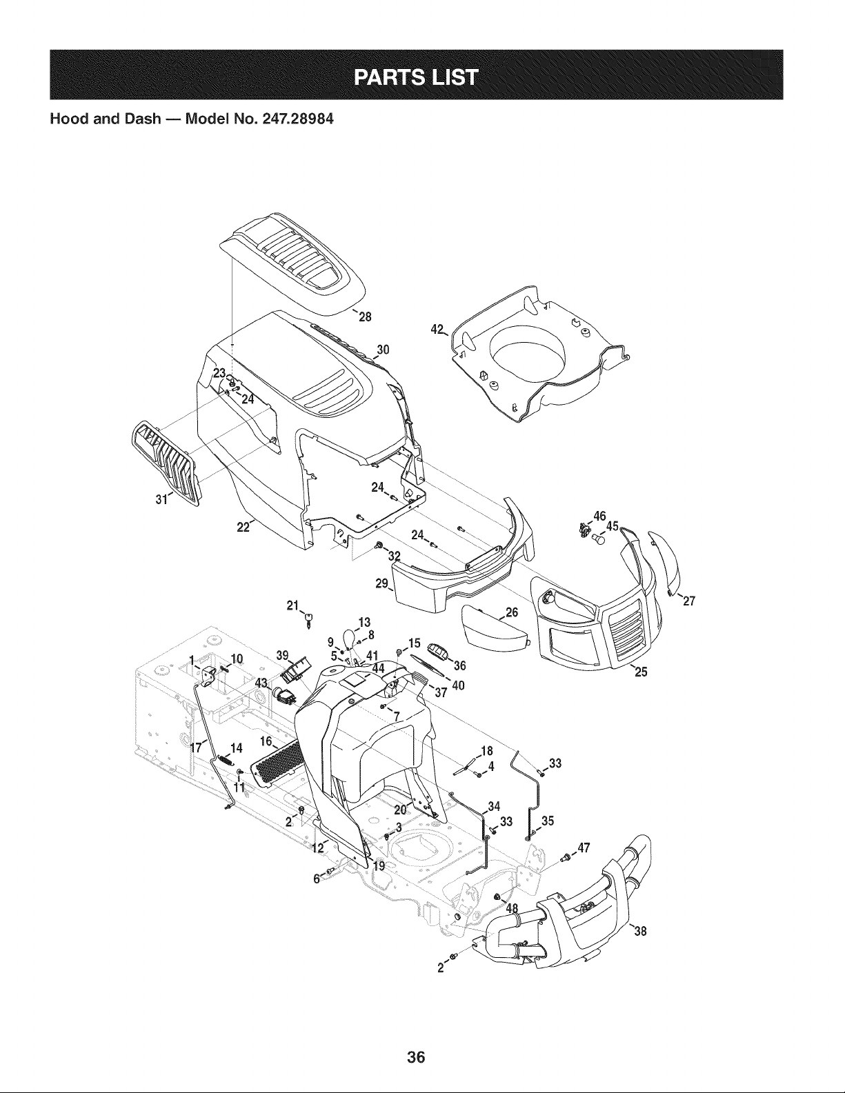
Hood and Dash B Model No. 247.28984
29
35
36

Hood and Dash B IViodel No. 247.28984
631-04353P DashLever 731-07458 RHLens
2 710-04484 TaptiteScrew,LockWasher,5/16-18:.750 i27 731-07459 LH Lens
3 710-0599 TaptiteScrew,LockWasher,1/4-20:0.500 i28 931-07461 HoodScoop
4 710-0895 Hi-LoScrew,LockWasher,1/4-15:0.750 i29 731-07467 LowerGrill
5 710-1017 Screw,1/4-14:0.625 i30 731-07469 LH HoodScoop
6 710-1611B TaptiteScrew,5/16-18:0.750 i31 731-07470 RH HoodScoop
7 710-1652 TaptiteScrew,1/4-20x .625 i32 738-04091A ShoulderScrew,.43x .29:TT:5/16-18
8 710-3217 MachineScrew,#8-32:0.375 i33 710-0642 TaptiteScrew,1/4-20:0.750
9 712-0142 HexNut,#8-32:GRA i34 747-05049 RHTankSupportRod
10 714-04040 Bow-tieCotterPin i35 747-05050 LHTankSupportRod
11 726-3046 RatchetClip:.250DIA i36 751-0603A FuelCap
12 731-07456 Dash i37 951-10573 FuelTank,2.75 Gallons
13 731-07550 ControlKnob i38 689-00157 GuardAssembly
14 732-04580 ExtensionSpring,.500DIAx 2.733LG i39 725-04992 KeySwitchModule
15 735-0271A Bumper i40 735-04170 FueITankGasket
16 735-04076 AccessoryNet i41 746-1100 ThrottleControl
17 747-05280 ControlRodLatch i42 731-07495 P-StylePlen
18 747-1196 LeverRod i43 725-04258 PTOSwitch
19 783-04285F-0637RH DashSupportPlate J44 925-04036C HourMeter
20 783-04323F-0637LH DashSupportPlate i45 925-0963 MiniatureLamp,12V
21 625-04124 Key(Set of 2) i46 925-1649 LampSocket
22 683-04618-0691 HoodAssembly i47 738-0143 ShoulderBolt,.496x .336:3/8-16
23 710-04187 Hi-loScrew,LockWasher,1/4-15:0.50 i48 712-04065 FlangelockNut,3/8-16
24 710-05108 Screw,Lock Washer,1/4DIA:.750 -- 777X44365 RHReflectorLabel(Not Shown)
25 931-07457 Grill -- 777X55366 LH ReflectorLabel(Not Shown)
37
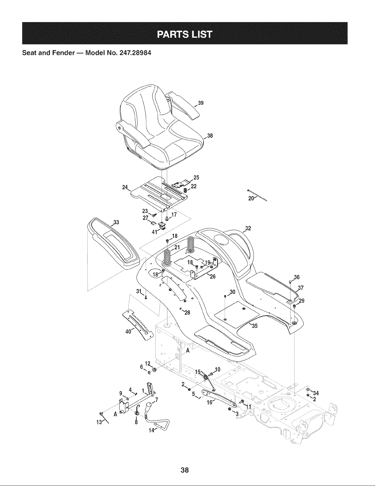
Seat and Fender B IViodel No. 247.28984
39
33
23
2\
25
32
38

Seat and Fender B IViodel No. 247.28984
683-04301-0637 Lift Shaft Assembly 732-04563 CompressionSpring,.68x 1.065x .055
2 712-04063 FlangelockNut,5/16-18 i23 938-0296 ShoulderScrew,.437x .268:5/16-18
3 712-04065 FlangelockNut,3/8-16 i24 783-06049-0691 Seat MountingBracket
4 914-0104 CotterPin,.072DIA.x 1.13LG i25 783-06050 SeatAdjustmentLever
5 714-04040 Bow-TieCotterPin i26 783-06088-0691 Seat PivotBracket
6 716-0106A E-Ring,.625DIA.SHAFT i27 783-06448 SwitchRetainerClip
7 720-04150 HandleGrip i28 710-04187 Hi-LoScrew,LockWasher,1/4-15:0.50
8 732-0874 TorsionSpring i29 710-0451 CarriageBolt,5/16-18:.750
9 736-0105 SpringWasher,.401x .870x .063 i30 710-0599 TaptiteScrew,LockWasher,1/4-20:0.500
10 738-0138A ShoulderScrew, .437x .470:5/16-18 i31 710-0895 Hi-LoScrew,LockWasher,1/4-15:0.750
11 938-0380 ShoulderBolt, .500x.270:3/8-16 i32 731-05837 LH FenderCover
12 941-0225 Hex FlangeBearing i33 731-06754 RH FenderCover
13 i746-0968 Lift Cable, 16.16LG i34 736-3078 FlatWasher,.344x 1.00x .063 HDN
14 i747-04962A Lift Handle i35 783-06118-0691 Fender
15 i756-04331 PulleyRollerCable i36 726-3046 RatchetClip
16 i783-05546A-0637LiftArm i37 735-04137 LH FootPad
17 710-04482 HexHeadFlange,3/8-16:.875 -- 735-04139 RHFootPad
18 710-04484 TaptiteScrew,LockWasher,5/16-18:.750 38 757-04128 Seat
19 712-3004A FlangelockNut,5/16-18 i39 757-04134 Armrests
20 i725-0157 CableTie, 3/16x.05x 7.4 i40 783-06181-0637 LiftBracket
21 732-04561 CompressionSpring,1.71x 3.735x .238 i41 925-05013 Seat Switch
39
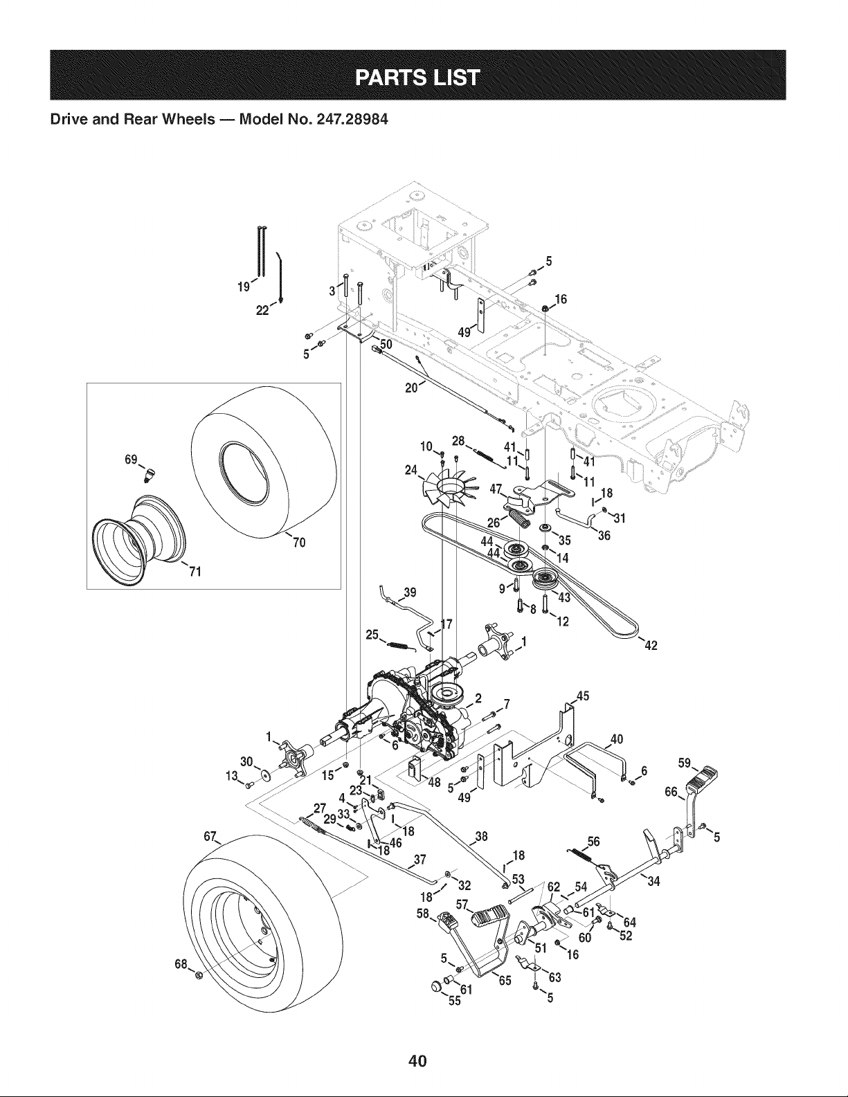
Drive and Rear Wheels B Model No. 247.28984
69
7O
24
27
49
38
5
18
16
4O
56
55
16
4O

Drive and Rear Wheels B Model No. 247.28984
918-04317 WheelAssemblyHub 747-05124 BrakeRod
2 918-04917 Transmission i38 747-05125A ControlRod
3 710-0189 HexScrew,5/16-18:3.00 i39 747-05130 DisengageRod
4 710-0227 Screw,#8-18:0.500 i40 747-05181 BeltKeeper,5/16
5 710-04484 TaptiteScrew,5/16-18:.750 i41 750-04456 Spacer,260 x .372x 1.420LG
6 710-0599 TaptiteScrew,1/4-20:0.500 i42 954-04244A V Belt,4Lx 77.0
7 710-0909A TaptiteScrew,5/16-18:1.750 i43 756-04224 Fiat IdlerPulley,2.75OD
8 710-1007 TaptiteSeresScrew,3/8-16:1.500 i44 756-04325 V IdlerPulley,3.06
9 710-1008 TaptiteSeresScrew,3/8-16:1.875 i45 783-05443A-0637TorqueBracket
10 710-1189 Screw,#12-24:0.625 i46 783-05841 SwitchBracket
11 710-1325 TaptiteScrew,1/4-20:1.625 i47 783-06027A Center IdlerBracket
12 710-3011 Hex Screw,3/8-16:2.25 i48 783-06501A-0637DeckBracket
13 710-3119 Hex Screw,3/8-16:.750 i49 783-06503 PlateBracket
14 712-0240 Jam Nut,7/16-20 i50 783-0693A-0637 Axle Bracket
15 712-04063 FlangelockNut,5/16-18 i51 683-04571 PedalBracketAssembly
16 712-04065 FlangelockNut,3/8-16 i52 710-0604A TaptiteScrew,5/16-18:0.625
17 914-0104 CotterPin,.072DIA.x 1.13LG i53 711-05068 ClevisPin,5/16x 3.985
18 914-0111 CotterPin,3/32:1.0 i54 714-04040 Bow-TieCotterPin
19 725-0157 CableTie,3/16x .05x 7.4 55 726-0214 PushCap
20 725-04791A JumperHarness i56 732-04587 ExtensionSpring,.63 DIAx 4.95LG
21 725-1644 ShortSpringSwitch i57 735-04118A ForwardPedal Pad
22 926-0154 PushMountCableTie 7.5LG i58 735-04135 ReversePedal Pad
23 926-0320 InsulatorNut Plate i59 735-04136 BrakePedal Pad
24 931-1449A BladeFan 60 938-0380 ShoulderBolt,.500x .270:3/8-16
25 732-04528 ExtensionSpring,.50DIA x 5.0 LG i61 741-0495 FlangeBearing,.630 ID x .695ODx .60
26 732-04624 ExtensionSpring,1.00DIAx 4.75 i62 748-04203 CruiseLatch
27 732-0716D ExtensionSpring,.59ODx 4.00 LG i63 783-05914 PedalSupportBracket
28 732-0932 ExtensionSpring,.38DIA x 5.6 i64 783-05940 PedalSupportBracket,5/8
29 732-3118 ExtensionSpring,.375OD x 1.44LG i65 783-06059-0637 DrivePedalBracket
30 936-0227 Flat Washer,.390x 1.500x .134 i66 783-06103A-0637BrakePedal Bracket
31 936-0264 Flat Washer,.330x .630x .0635 67 634-0202A-0961 CompleteWheel
32 936-3008 Flat Washer,.344 x .750x .120 i68 712-3050 LugNut,7/16-14
33 736-3010 Flat Washer,.407x .812x .135 i69 934-0255 Air Valve
34 647-04152A BrakeControlAssembly i70 734-04147-0901 Tire
35 738-04420 ShoulderSpacer,1.375x .380x .183 i71 634-04238-4042 RimAssembly
36 747-04957A FootpedalBypassTransmissionRod
41
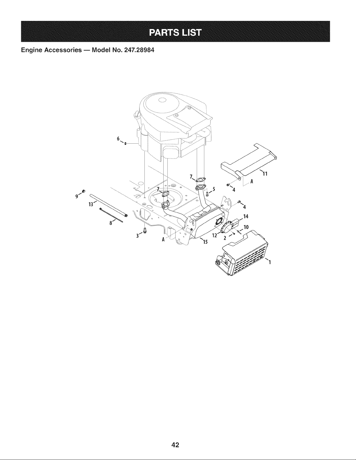
Engine Accessories B IViodel No. 247.28984
4b
9/
42

Engine Accessories B Model No. 247.28984
683-04549-0637 MulfflerShieldAssembly
i2 710-0227 Screw,IndentedWasher,#8-18:0.500
i3 710-04683 TaptiteScrew,IndentedWasher,3/8-16:1.000
i4 710-0599 TaptiteScrew,IndentedWasher,1/4-20:0.500
i5 710-1314A SocketHeadScrew,5/16-18:.750
i6 712-0271 SeresNut, 1/4-20
i7 721-0460 ExhaustGasket
i8 725-0157 CableTie,3/16x .05 x 7.4
i9 726-0205 HoseClamp,.490DIA.
i10 728-04000 Rivet,.188DIA x .300L
ill 783-06378A HeatShield
i12 751-0564B MufflerDeflector
i13 751-10349 FuelHose
i14 751-10353 LongMufflerDeflector
i15 751-10542A MufflerDeflector
43
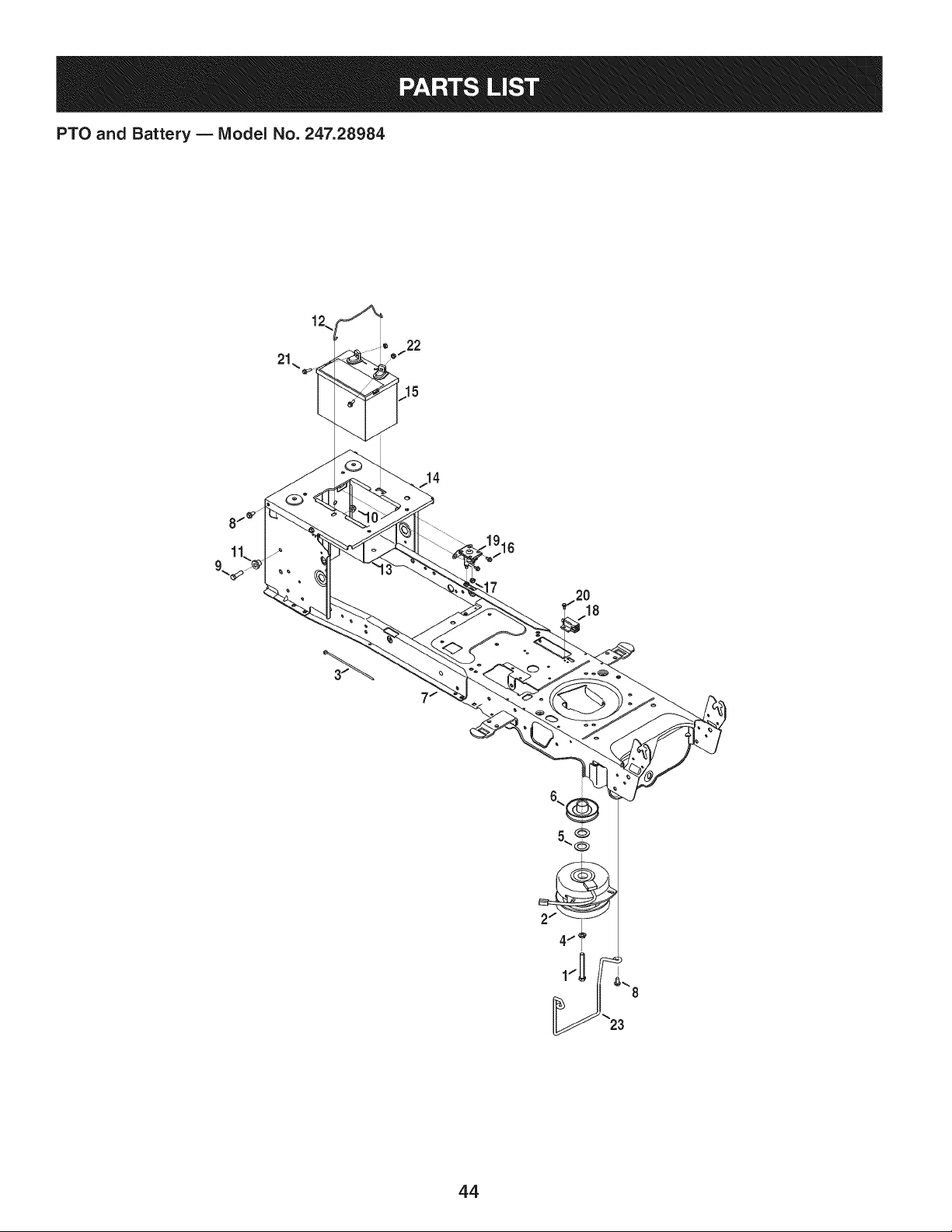
PTO and Battery B IViodel No. 247.28984
22
15
7
18
44

PTO and Battery B IViodel No. 247.28984
710-04379A HexHeadScrew,7/16-20:3.50
2 917-1774C ElectricPTOClutch
3 725-0157 CableTie,3/16x .05x 7.4
4 936-0171 LockWasher,7/16
5 736-0277 FiatWasher,1.031x 1.620x .095
6 756-0978B ElectricPTOEnginePulley
7 683-04469A-0691Frame
8 710-04484 TaptiteScrew,indentedWasher,5/16-18:.750
9 710-3005 HexHeadScrew,3/8-16:1.25
10 712-04065 FlangelockNut,3/8-16
11 738-04058 ShoulderSpacer,.38x 1.0x .70
12 747-04121A BatteryHolderRod
13 783-0349-0637 BatteryTray
14 783-06089-0637 SeatFrameBracket
15 725-05088 Battery
16 710-0653 TaptiteScrew,1/4-20:0.375
17 712-04064 FlangelockNut, 1/4-20
18 725-04363 interlockSwitch
19 725-04439 Solenoid,12V
20 738-04237A ShoulderScrew,#10-32:.500
21 710-04666 HexHeadFlange,1/4-20:.75
22 712-0271 SeresNut, 1/4-20
23 747-05195 BeltKeeperRod
NS 925-04093 Wire HarnessAssembly
45
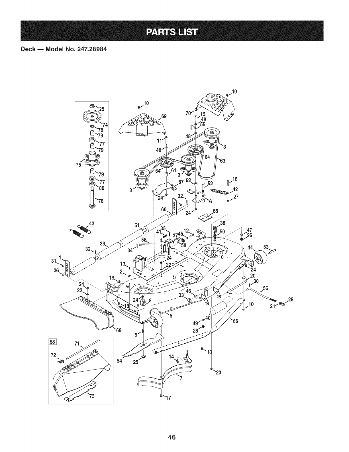
Deck B IViodel No. 247.28984
43
51
34
10
29
[]
71
54
25
46

Deck B Model No. 247.28984
12650 HeightAdjustBracket 732-04652 CompressionSpring,.535 ODx 1.751LG
2 96606 RetainerHookBracket i42 732-04692 ExtensionSpring,.85 ODx 5.915LG
3 918-0671D SpindleAssembly i43 732-0934 ExtensionSpring,1.15OD x 5.99 LG
4 683-0254B-4028 DeckHangerBracketAssembly i44 734-04155 DeckWheel
5 983-04585-4028 DeckAssembly i45 936-0119 LockWasher,5/16
6 683-0459-0637 IdlerAssembly i46 936-0179 FiatWasher,.531x 1.25x .100
7 703-2093-0637 InnerBaffle i47 736-0225 LockWasher,5/8
8 703-3279-4028 DeflectorChuteStop i48 936-0300 FlatWasher,.406x .875x .059
9 710-04095 HexScrew,3/8-16:1.00 i49 936-0921 LockWasher, 1/2
10 710-04484 TaptiteScrew,5/16-18:.750 i50 737-04003D DeckWater Nozzle
11 710-0521 Hex Screw,3/8-16:3.00 i51 738-0295 Shaft, .750x .47.12
12 710-0528 HexScrew,5/16-18:1.25 i52 738-1229A ShieldScrew,.625x2.50:1/2-13
13 710-0597 HexScrew,1/4-20:1.00 i53 938-3056 ShoulderBolt,.496x2.50:3/8-16
14 710-0623 TaptiteScrew,3/8-16:0.750 i54 942-0677B Blade
15 710-0859 HexScrew,3/8-16:2.50 i55 747-04938 BeltKeeperRod
16 710-3103 HexScrew,5/16-18:2.00 i56 747-05141A DeckLiftRod
17 710-3168 CarriageBolt,3/8-16:1.00 i57 712-04064 FlangelockNut, 1/4-20
18 710-3178 CarriageBolt,3/8-16:0.75 i58 747-05284 DeckSwayRod
19 911-0332 ClevisPin,.50 DIAx.78 LG 59 747-1116 DeckReleaseHandleRod
20 911-3314 RollerPin, 1/2DIAx 7.31LG i60 950-0212 Spacer,.82 IDx 1.00OD x .53
21 912-0206 Hex Nut, 1/2-13 i61 750-04597 Spacer,.380x.900x 1.313
22 712-0229 PushNut,3/8 i62 750-0933 Spacer,.385 IDx .88 x .64
23 712-04063 FlangelockNut,5/16-18 i63 954-04083 V Belt
24 712-04065 FlangelockNut,3/8-16 64 756-04129B IdlerPulley,4.25"DIA
25 712-0417A FlangeNut,5/8-18 i65 783-04013A-0637PulleyStabilizerBracket
26 912-0641 Hex Nut,M16-1.5DIN936 i66 783-04690B-0637DeckSkirt
27 912-3010 Hex Nut,5/16-18 i67 783-04726-0637 Stationaryldler Bracket
28 712-3022 HexlockNut,Counterlock,1/2-13 i68 631-04070A ChuteAssembly
29 712-3083 HexlockNut, 1/2-13 i69 783-1470A-4028 RHSpindleCover
30 914-0111 CotterPin, 3/32:1.0 i70 783-1471-4028 LHSpindleCover
31 914-0145 Click Pin,.092x 1.64LG 71 711-04565 HingePin
32 714-0162 CotterPin,5/32:1.25 i72 732-04372 TorsionSpring,.44 IDx 2.0
33 753-04070 LynchPin,.1875 i73 783-05030 Chute Bracket
34 714-04040 BowTie CotterPin i74 756-04213 DeckPulley
35 914-0470 CotterPin, 1/8x 1.25 i75 937-3000 LubeFitting
36 715-0108 SpringPin, 1/4 DIAx 1.00LG 76 738-1197 SpindleShaft,6.95 LG
37 917-04074 DeckGear i77 941-0919 BallBearing,.787IDx 1.85OD x .551
38 921-04041 WaterNozzleAdaptor i78 748-0160A Spacer,.790IDx 1.25ODx.175
39 731-0335 DeckRoller i79 750-1000 Spacer,.80x 1.10x 1.322LG
40 731-05679 FrontRoller i80 750-1349A Spacer,.79x 1.82x.55 LG
4.7
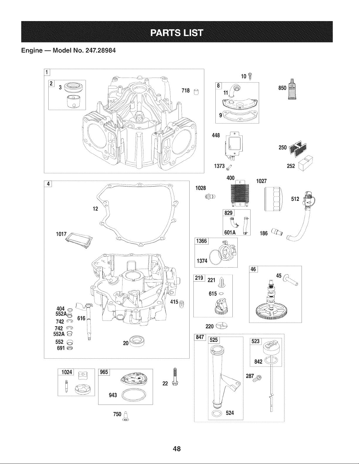
Engine B Model No. 247.28984
448
12
101
750 _\
1028
1373_
400
220 (,_!;_
i
524
1601A
850
250
/
252 /
1027
512
/ /
45
48

Engine B Model No. 247.28984
387
918
385 t_ ,i
1169
{j;N_ o, <o /
163
r......... <_ ......... l
lO617/672\o _J
........J_Y
1124<_-_
JJ
_J
JJ
))
H
H
27 ©i
25
! I
i i
ii'
iHii
24 [_
1436
1437_
163
51A 51A
', /.;\ \L i_
49
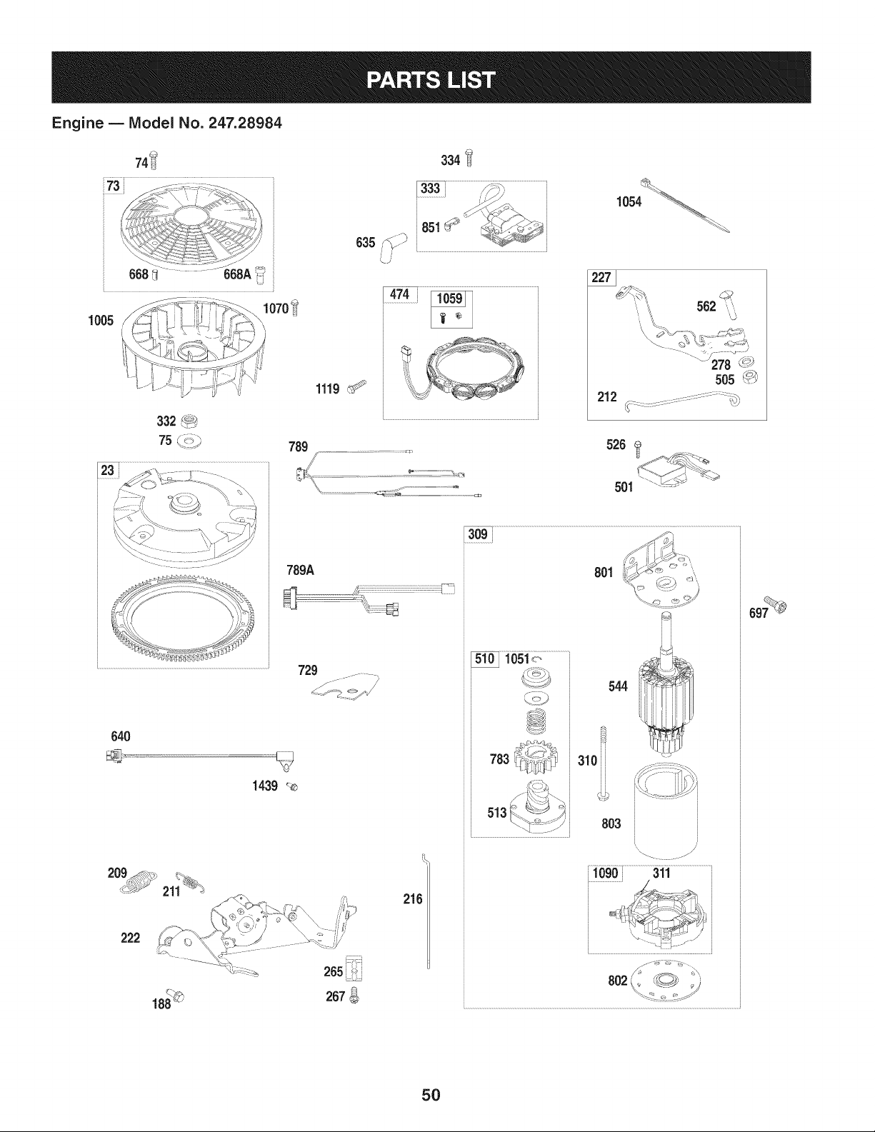
Engine B Model No. 247.28984
74i
/'/7///i_& :,if _]' .... ,_ \
,\ - , ,i= ]¢(rSI ,
....kisY
008 i ....... --_168A
1070_
1005
332 _9_
75 _"_"_
334
333
851
635/>_) ..............................................................................................................................
789
-_ ,+cD
789A
.....................................................................................................................................................................729
1439 _
1054
......t:,,it_ 562
212
640
309
, .........................
310i
544
803
222
207
216
.....i60oi.............................3"i_i..........................................
:-7':7"-J
5O

Engine B IViodel No. 247.28984
883
868
1022
35 :_
1029
1100_
798_¢'
1026 _>_
1026A _
850
914
635
i42
i..............
1022
35
1029
798_
1
51
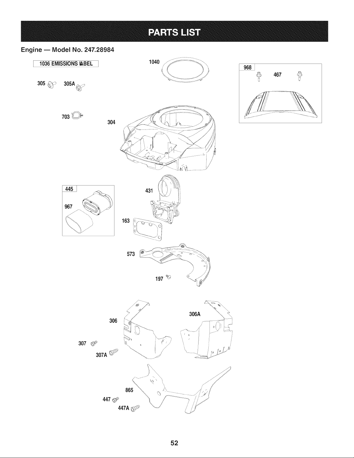
Engine B IViodel No. 247.28984
1036EMiSSiONS_BEL
703 _,
304
1O4O
467
431
163
573
306
307 _ '%
307A_
865
306A
52
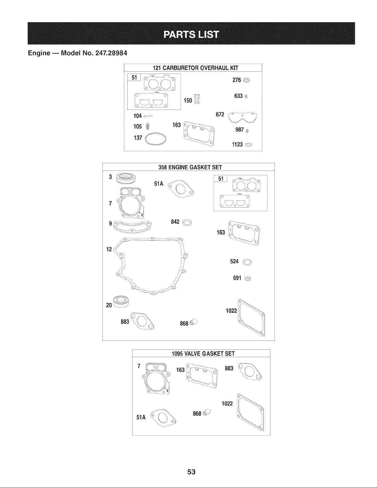
Engine B Model No. 247.28984
121CARBURETOROVERHAULKIT
276 _
104 ....
105 !_
137
633_
15o
163
672
[ 'i
163
1022
1095VALVEGASKETSET
_\-_'_9_.__oo 163 i0_ O__,-\
883
51A
868_>3_
1022
53

Engine B IViodel No. 247.28984
_= o !
BS-796908 Cylinder Assembly
2 BS-499585 Bushing/SealKit (MagnetoSide)
3 BS-391086s Seal-Oil (MagnetoSide)
4 BS-797502 Sump-Engine
5 BS-796270 Head-Cylinder(Cylinder#1)
5A BS-796271 Head-Cylinder(Cylinder#2)
7 BS-796851
8 BS-792185
9 BS-690937
10 BS-697551
11 BS-792184
Gasket-CylinderHead
BreatherAssembly
Gasket-Breather(Liquid GasketandThe
BreatherGasketAre Interchangeable)
Screw(BreatherAssembly)
Tube-Breather
12 BS-697227 Gasket-Crankcase
13 BS-793988 Screw(Cylinder Head)
16 BS-796857 Crankshaft
20 BS-795387 Seal-Oil (PTOSide)
22 BS-694966 Screw(CrankcaseCover/Sump)
23 BS-691053 Flywheel
24 BS-796335 Key-Flywheel
25 BS-796909 PistonAssembly(Standard)
BS-796910 PistonAssembly(020" Oversize)
26 BS-796911 RingSet (Standard)
BS-796912 RingSet (.020"Oversize)
27 BS-690975 Lock-PistonPin
28 BS-696581 Pin-Piston
29 BS-796209 Rod-Connecting
32 BS-690976 Screw(ConnectingRod)
33 BS-793557 Valve-Exhaust
34 BS-793556 Valve-Intake
35 BS-694865 Spring-Valve(Intake)
36 BS-694865 Spring-Valve(Exhaust)
42 BS-499586 Keeper-Valve
45 BS-690977 Tappet-Valve
46 BS-796853 Camshaft
48 BS-797511 Short Block
50 BS-796878 Manifold-Intake
51 BS-796876 Gasket-Intake
51A BS-690949 Gasket-Intake
53 BS-690951 Stud (Carburetor)
54 BS-699816 Screw(IntakeManifold)
73 BS-494439 Screen-Rotating
I = 0
BS-698425 Screw(RotatingScreen)
75 BS-691056 Washer(Flywheel)
95 BS-690718 Screw(ThrottleValve)
98 BS-699721 Kit-IdleSpeed
104 BS-694918 Pin-FloatHinge
105 BS-797410 Valve-FloatNeedle
108 BS-699723 Valve-Choke
117 BS-842633 Jet-Main(Standard)(Left and RightJet)
118 BS-842082 Jet-Main(HighAltitude)(Leftand RightJet)
121 BS-796919 Kit-CarburetorOverhaul
122 BS-796877 Spacer-Carburetor
125 BS-796870 Carburetor
130 BS-796875 Valve-Throttle
131 BS-796872 Kit-ThrottleShaft
133 BS-699724 Float-Carburetor
135 BS-699729 Tube-FuelTransfer
137 BS-690994 Gasket-FloatBowl
141 BS-796228 Kit-ChokeShaft
142 BS-796871 Nozzle-Carburetor
146 BS-690979 Key-Timing
150 BS-690995 Gasket-Nozzle
163 BS-691001 Gasket-AirCleaner
186 BS-796532 Hose-Connector(Oil DrainHose)
187 BS-791766 Line-Fuel (Cutto RequiredLength)
188 BS-697551 Screw(ControlBracket)
192 BS-690083 Adjuster-RockerArm
197 BS-697820 Screw(Back Plate)
209 BS-796849 Spring-Governor(Yellow/Purple)
211 BS-796225 Spring-GovernedIdle (Orange)
212 BS-695238 Link-Throttle
216 BS-796879 Link-Choke
217 BS-695409 Spring-ChokeReturn
219 BS-793338 Gear-Governor
220 BS-690412 Washer(GovernorGear)
221 BS-841026 Cup-Governor
222 BS-796630 Bracket-Control
227 BS-796223 Lever-GovernorControl
231 BS-690718 Screw(ChokeValve)
240 BS-695666 Filter-Fuel
250 BS-690957 Retainer-Breather
252 BS-794389 Collector-Oil
54
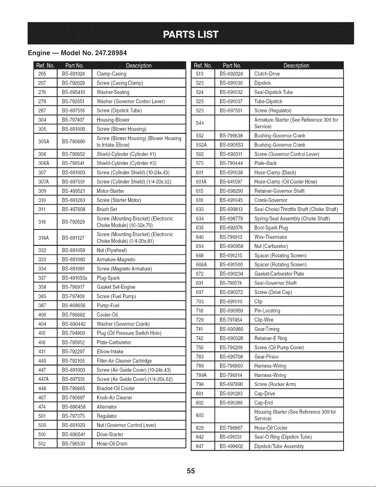
Engine B IViodel No. 247.28984
BS-691024 Clamp-Casing
267 BS-792629 Screw(CasingClamp)
276 BS-695410 Washer-Sealing
278 BS-792651 Washer(GovernorControlLever)
287 BS-697551 Screw(DipstickTube)
304 BS-797407 Housing-Blower
305 BS-691005 Screw(Blower Housing)
Screw(Blower Housing)(Blower Housing
305A BS-790690
to IntakeElbow)
306 BS-796852 Shield-Cylinder(Cylinder#1)
306A BS-796541 Shield-Cylinder(Cylinder#2)
307 BS-691003 Screw(CylinderShield) (10-24x.43)
307A BS-697551 Screw (CylinderShield) (1/4-20x.62)
309 BS-499521 Motor-Starter
310 BS-691263 Screw(Starter Motor)
311 BS-497608 Brush Set
Screw(MountingBracket)(Electronic
318 BS-792629
ChokeModule)(10-32x.70)
Screw(MountingBracket)(Electronic
318A BS-691127
ChokeModule)(1/4-20x.81)
332 BS-691059 Nut (Flywheel)
333 BS-691060 Armature-Magneto
334 BS-691061 Screw(MagnetoArmature)
337 BS-491055s Plug-Spark
358 BS-796917 GasketSet-Engine
385 BS-797409 Screw(Fuel Pump)
387 BS-808656 Pump-Fuel
400 BS-796882 Cooler-Oil
404 BS-690442 Washer(GovernorCrank)
415 BS-794903 Plug(Oil PressureSwitch Hole)
418 BS-795912 Plate-Carburetor
431 BS-792297 Elbow-Intake
445 BS-792105 Filter-AirCleaner Cartridge
447 BS-691003 Screw(Air GuideCover)(10-24x.43)
447A BS-697551 Screw (Air GuideCover)(1/4-20x.62)
448 BS-796865 Bracket-OilCooler
467 BS-790697 Knob-AirCleaner
474 BS-696458 Alternator
501 BS-797375 Regulator
505 BS-691029 Nut (GovernorControlLever)
510 BS-696541 Drive-Starter
512 BS-796530 Hose-OilDrain
D = W O
BS-692024 Clutch-Drive
523 BS-691036 Dipstick
524 BS-691032 Seal-DipstickTube
525 BS-691037 Tube-Dipstick
523 BS-697551 Screw(Regulator)
Armature-Starter(See Reference309for
544
Service)
552 BS-796638 Bushing-GovernorCrank
552A BS-690553 Bushing-GovernorCrank
562 BS-690311 Screw(GovernorControl Lever)
573 BS-790444 Plate-Back
601 BS-691038 Hose-Clamp(Black)
601A BS-841597 Hose-Clamp(Oil CoolerHose)
615 BS-698290 Retainer-GovernorShaft
616 BS-691045 Crank-Governor
633 BS-699813 Seal-Choke/ThrottleShaft (ChokeShaft)
634 BS-698779 Spring/SealAssembly(ChokeShaft)
635 BS-692076 Boot-SparkPlug
640 BS-796913 Wire-Thermistor
654 BS-690958 Nut (Carburetor)
668 BS-691215 Spacer(RotatingScreen)
668A BS-691500 Spacer(RotatingScreen)
672 BS-690234 Gasket-CarburetorPlate
691 BS-790574 Seal-GovernorShaft
697 BS-690372 Screw(DriveCap)
703 BS-691010 Clip
718 BS-690959 Pin-Locating
729 BS-797454 Clip-Wire
741 BS-690980 Gear-Timing
742 BS-690328 Retainer-ERing
750 BS-796208 Screw(Oil PumpCover)
783 BS-695708 Gear-Pinion
789 BS-796860 Harness-Wiring
789A BS-796914 Harness-Wiring
798 BS-697890 Screw(RockerArm)
801 BS-691283 Cap-Drive
802 BS-691286 Cap-End
803 Housing-Starter(See Reference309 for
Service)
829 BS-796867 Hose-OilCooler
842 BS-691031 Seal-O Ring(DipstickTube)
847 BS-499602 Dipstick/TubeAssembly
55

Engine B IViodel No. 247.28984
D = 0
BS-100106 Sealant-Liquid
851 BS-493880s Terminal-SparkPlug
865A BS-792286 Cover-AirGuide(Valley)
868 BS-690968 Seal-Valve
883 BS-690970 Gasket-Exhaust
914 BS-691127 Screw(Rocker Cover)
918 BS-797408 Hose-Vacuum
943 BS-796222 Seal-O Ring (Oil PumpCover)
947 BS-841546 Solenoid-Fuel
965 BS-796221 Cover-OilPump
967 BS-792303 Filter-PreCleaner
968 BS-795120 Cover-AirCleaner
975 BS-793592 Bowl-Fuel
987 BS-691000 Seal-ThrottleShaft
1005 BS-791236 Fan-Flywheel
1017 BS-796214 Screen-Oil Pump
1022 BS-690971 Gasket-RockerCover(LiquidGasketand
RockerCoverGasketare Interchangeable)
1023 BS-793146 Cover-Rocker(Cylinder#1)
1023A BS-499600 Cover-Rocker(Cylinder#2)
1024 BS-796220 Pump-Oil
1026 BS-690981 Rod-Push(Steel)(Exhaust)
1026A BS-690982 Rod-Push(Aluminum)(Intake)
1027 BS-696854 Filter-Oil
1028 BS-796864 Adapter-OilFilter
1029 BS-690972 Arm-Rocker
Label-Emissions(Availablefrom a Briggs
1036
& StrattonAuthorizedDealer)
1040 BS-791237 Plate-Trim
1051 BS-691265 Ring-Retaining
1054 BS-280275 Tie-Cable
1058 BS-278776 Operator'sManual
1059 BS-698516 Kit-Screw/Washer(Alternator)
1070 BS-791680 Screw(FlywheelFan)
1090 BS-691293 Retainer-Brush
1095 BS-796920 GasketSet-Valve
1000 BS-791959 Pivot-RockerArm
1119 BS-691183 Screw(Alternator)
1124 BS-841653 Seal-O Ring (FuelTransferTube)
1124A BS-690988 Seal-O Ring (FuelTransferTube)
1126 BS-841653 Screw(FuelTransferTube)
I = O O
BS-695407 Screw(FloatBowl)
1128 BS-690990 Screw(CarburetorNozzle)
1169 BS-690990 Screw(CarburetorCoverPlate)
1366 BS-796866 Diverter-OilCooler
1373 BS-695629 Screw(OilCooler Bracket)
1374 BS-796863 Seal-O Ring(Oil CoolerDiverter)
1436 BS-796918 Motor-Stepper/Bracket
1437 BS-699891 Screw(Stepper/BracketMotor)
1438 BS-796532s Module-ElectronicChoke
1439 BS-690635 Screw(ThermistorWireAssembly)
1329 BS-49M877-OO47-G1 Replacement Engine
56
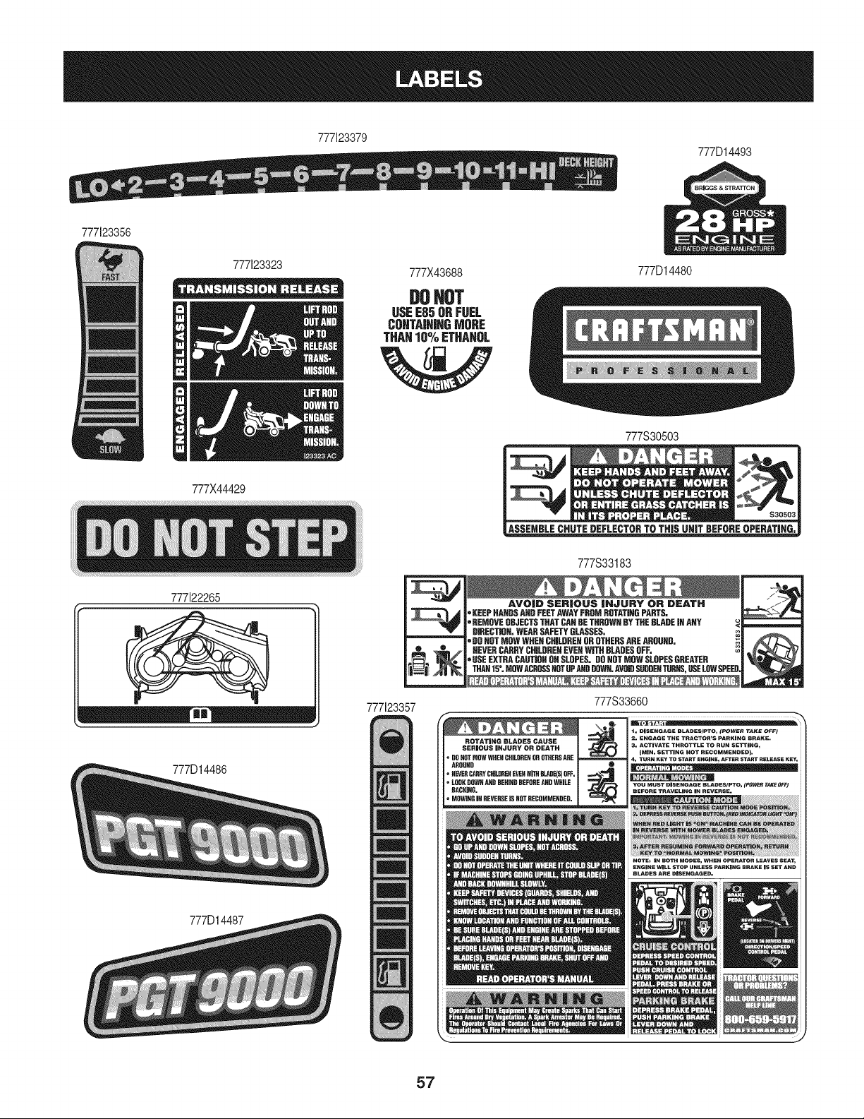
777123379
777D14493
777123356
777X44429
777122265
777D14486
777D14487
777X43688 777D14480
DOHOT
USEE85ORFUEL
CUNTA|N|HGMORE
THAN10%ETHAHOL
i_,dJ
777123357
777S30503
mmz_ $30503
777S33183
AVOID SERIOUS |NJURY OR DEATH
_'KEEPHANGSANDFEETAWAYFROMROTATINGPARTS.
,REMOVEOBJECTSTHATCANBETHROWNBYTHEBLADEJNANY
DIRECTION,WEARSAFETYGLASSES.
,DOHOTMOWWRENCHILDRENOROTHERSAREAROUND.
NEVERCARRYCHILDREHEVEHWiTHBLADESOFF.
,USEEXTRACAUTJQHONSLOPES.DOHOTMOWSLOPESGREATER
THAN15°, MOWACROSSHOTOFAHDDOWN.AVW SUDDENTUBHS,USELOWSPEE
777S33660
CHILDREHOR_ERS ARE
AROUND J •
_HIHH BEFOREANDWHILE J
HACHIHG. I
_RSE ISN_ RECOMMEHDED.
57
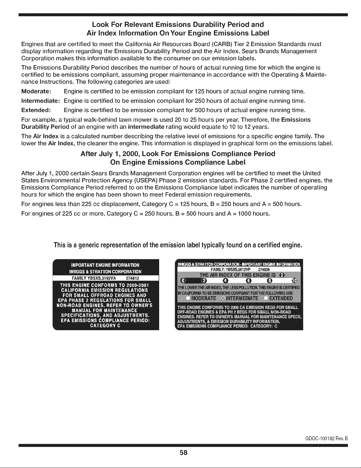
Look For Relevant Emissions Durability Period and
Air index information On Your Engine Emissions Label
Engines that are certified to meet the California Air Resources Board (CARB) Tier 2 Emission Standards must
display information regarding the Emissions Durability Period and the Air Index. Sears Brands Management
Corporation makes this information available to the consumer on our emission labels.
The Emissions Durability Period describes the number of hours of actual running time for which the engine is
certified to be emissions compliant, assuming proper maintenance in accordance with the Operating & Mainte-
nance Instructions. The following categories are used:
Moderate: Engine is certified to be emission compliant for 125 hours of actual engine running time.
Intermediate: Engine is certified to be emission compliant for 250 hours of actual engine running time.
Extended: Engine is certified to be emission compliant for 500 hours of actual engine running time.
For example, a typical walk-behind lawn mower is used 20 to 25 hours per year. Therefore, the Emissions
Durability Period of an engine with an intermediate rating would equate to 10 to 12 years.
The Air index is a calculated number describing the relative level of emissions for a specific engine family. The
lower the Air Index, the cleaner the engine. This information is displayed in graphical form on the emissions label.
After July 1,2000, Look For Emissions Compliance Period
On Engine Emissions Compliance Label
After July 1, 2000 certain Sears Brands Management Corporation engines will be certified to meet the United
States Environmental Protection Agency (USEPA) Phase 2 emission standards. For Phase 2 certified engines, the
Emissions Compliance Period referred to on the Emissions Compliance label indicates the number of operating
hours for which the engine has been shown to meet Federal emission requirements.
For engines less than 225 cc displacement, Category C = 125 hours, B = 250 hours and A = 500 hours.
For engines of 225 cc or more, Category C = 250 hours, B = 500 hours and A = 1000 hours.
This is a generic representation of the emission label typically found on a certified engine.
FAMILYYBSXS.3192VA 274812
GDOC-100182Rev.B
58

(Thispageapplicableinthe U.S.A.and Canadaonly.)
Sears Brands Management Corporation (Sears), the California Air Resources Board (CARD)
and the United States Environmental Protection Agency (U.S. EPA)
Emission Control System Warranty Statement (Owner's Defect Warranty Rights and Obligations)
EMISSIONCONTROLWARRANTYCOVERAGEISAPPLICABLETOCERTI-
FIEDENGINESPURCHASEDIN CALIFORNIAIN 1995ANDTHEREAF-
TER,WHICHARE USEDINCALIFORNIA,ANDTOCERTIFIEDMODEL
California and United States Emission
The CaliforniaAir ResourcesBoard(CARD),U.S.EPAand Searsare pleased
to explainthe EmissionControlSystemWarrantyonyour modelyear2000and
latersmalloff-roadengine(SORE).InCalifornia,newsmall off-roadengines
mustbe designed,builtand equippedto meettheState'sstringentanti-smog
standards.Elsewherein theUnitedStates,newnon-road,spark-ignition
enginescertifiedfor modelyear 1997and latermustmeetsimilarstandardsset
forth bythe U.S.EPA.Sears mustwarranttheemissioncontrol systemon your
YEAR 1997AND LATERENGINESWHICHARE PURCHASEDANDUSED
ELSEWHEREIN THE UNITEDSTATES(ANDAFTERJANUARY1,2001 IN
CANADA).
Control Defects Warranty Statement
enginefor theperiodsoftime listedbelow,providedtherehas been noabuse,
neglector impropermaintenanceof your smalloff-roadengine.Youremis-
sion controlsystemincludespartssuch as thecarburetor,air cleaner,ignition
system,mufflerand catalyticconverter.Also includedmay be connectorsand
otheremissionrelatedassemblies.Wherea warrantableconditionexists,Sears
will repairyour smalloff-roadengineat no costto you includingdiagnosis,parts
and labor.
Sears Emission Control Defects Warranty Coverage
Smalloff-roadenginesarewarrantedrelativeto emissioncontrol partsdefects
fora periodof one year,subjectto provisionsset forthbelow.Ifany covered
Owner's Warranty
Asthe smalloff-roadengine owner,you are responsiblefor the performanceof
therequiredmaintenancelistedin yourOperatingand MaintenanceInstruc-
tions.Searsrecommendsthatyou retainall yourreceiptscoveringmaintenance
on yoursmalloff-roadengine,butSears cannotdenywarrantysolelyfor the
lackof receiptsor for yourfailureto ensurethe performanceof all scheduled
maintenance.As the smalloff-roadengineowner,you shouldhoweverbe
awarethat Searsmaydenyyou warrantycoverageif your smalloff-roadengine
ora part hasfailed dueto abuse,neglect,impropermaintenanceor unap-
parton yourengineis defective,the part willbe repairedorreplacedbySears.
Responsibilities
provedmodifications.Youare responsiblefor presentingyour smalloff-road
engineto an AuthorizedSearsServiceDealeras soonas a problemexists.The
undisputedwarrantyrepairsshouldbe completedina reasonableamountof
time,notto exceed30 days.Ifyou haveany questionsregardingyourwarranty
rightsand responsibilities,youshouldcontacta SearsService Representative
at 1-800-469-4663.The emissionwarrantyis a defectswarranty.Defectsare
judgedon normalengineperformance.Thewarrantyis not relatedto an in-use
emissiontest.
Sears Emission Control Defects Warranty Provisions
ThefollowingarespecificprovisionsrelativetoyourEmissionControlDefectsWarrantyCoverage.ItisinadditiontotheSearsenginewarrantyfornon-regulated
enginesfound in the Operatingand MaintenanceInstructions.
1. WarrantedParts
Coverageunderthis warrantyextendsonly to the parts listedbelow (the
emissioncontrolsystemsparts)to the extentthese partswere presenton
the engine purchased.
a. FuelMeteringSystem
• Cold start enrichmentsystem
• Carburetorand internalparts
• FuelPump
b. Air lnduction System
• Air cleaner
• Intakemanifold
c. IgnitionSystem
• Spark plug(s)
• Magnetoignitionsystem
d. CatalystSystem
• Catalyticconverter
• Exhaustmanifold
• Air injectionsystemor pulsevalve
e. MiscellaneousItemsUsedin AboveSystems
• Vacuum,temperature,position,timesensitivevalves
andswitches
• Connectorsandassemblies
2. Lengthof Coverage
Searswarrantsto the initialownerand eachsubsequentpurchaserthat
the WarrantedParts shallbe free from defects in materialsandworkman-
shipwhich causedthefailure of the WarrantedPartsfor a periodof one
yearfrom the datethe engineis deliveredto a retailpurchaser.
3. NoCharge
Repairor replacementof anyWarrantedPartwill be performedat no
chargeto the owner,includingdiagnosticlabor whichleadsto the
determinationthata WarrantedPartis defective,if the diagnosticwork is
performedat an AuthorizedSears ServiceDealer.For emissionswarranty
servicecontact yournearestAuthorizedSearsServiceDealeras listed in
the "YellowPages"under"Engines,Gasoline,""GasolineEngines,""Lawn
Mowers,"or similar category.
4. Claimsand CoverageExclusions
Warrantyclaimsshall be filed in accordancewiththe provisionsof the
Sears EngineWarrantyPolicy.Warrantycoverageshall be excludedfor
failuresof WarrantedPartswhichare notoriginal Sears partsor because
of abuse, neglector impropermaintenanceas setforth inthe Sears
EngineWarrantyPolicy.Sears is not liableto coverfailuresof Warranted
Partscausedby theuse of add-on, non-original,or modifiedparts.
5. Maintenance
Any WarrantedPart whichis notscheduledfor replacementas required
maintenanceor whichis scheduledonly for regularinspectionto the effect
of "repairor replaceas necessary"shallbe warrantedasto defectsfor the
warrantyperiod.Any WarrantedPartwhich is scheduledfor replacement
as requiredmaintenanceshallbe warrantedasto defectsonly forthe
periodof time upto the first scheduledreplacementfor that part. Any
replacementpart that is equivalentin performanceand durabilitymay
be usedin the performanceof any maintenanceor repairs.The owneris
responsibleforthe performanceof all requiredmaintenance,as definedin
the SearsOperatingand MaintenanceInstructions.
6. ConsequentialCoverage
Coveragehereundershallextendto thefailure of any engine components
caused bythe failureof any WarrantedPartstill underwarranty.
Inthe USAandCanada,a 24 hour hot line, 1-800-469-4663,has a menu of pre-recordedmessagesofferingyou enginemaintenanceinformation.
GD0C-100188Rev.B
59

FEDERAL and/or CALIFORNIA EMISSION CONTROL WARRANTY STATEMENT
YOUR WARRANTY RIGHTS AND OBLIGATIONS
MTDConsumerGroupInc,the UnitedStatesEnvironmentalProtectionAgency (EPA),and, forthose productscertifiedfor sale in the stateof California,the
CaliforniaAir ResourcesBoard(CARB)are pleasedto explainthe emission(evaporativeand/or exhaust)controlsystem(ECS) warrantyon youroutdoor2006
andlater smalloff-roadspark-ignitedengine andequipment(outdoorequipmentengine)In California,new outdoorequipmentengines mustbe designed,built and
equippedto meetthe State'sstringentanti-smogstandards(inotherstates, 1997andlater modelyear equipmentmustbe designed,built, and equippedto meet
theU.S. EPAsmalloff-road, sparkignitionengine regulations.MTDConsumerGroupInc mustwarrantthe ECSon your outdoorequipmentenginefor the periodof
timelisted belowprovidedtherehas been no abuse, neglector impropermaintenanceof outdoor equipmentengine.
Your ECSmay includeparts such as thecarburetor,fuel-injectionsystem,the ignitionsystem,catalyticconverter,fuel tanks,fuel lines,fuel caps,valves,canisters,
filters,vapor hoses,clamps,connectors,andotherassociatedemission-relatedcomponents.
Wherea warrantableconditionexists, MTDConsumerGroupIncwill repairyouroutdoor equipmentengineat no cost to you includingdiagnosis,parts and labor.
MAN UFACTURER'S WARRANTY COVERAGE:
Thisemissioncontrolsystemis warrantedfor two years. If any emission-relatedpart on your outdoorequipmentengine is defective,the part will berepairedor
replacedby MTDCONSUMERGROUPINC.
OWNER'S WARRANTY RESPONSIBILITIES:
Asthe outdoorequipmentengineowner,you are responsiblefor performanceof the requiredmaintenancelisted inyour owner'smanual.MTDConsumerGroup
Inc recommendsthat you retainallreceiptscoveringmaintenanceon youroutdoor equipmentengine,butMTDConsumerGroupInc cannotdeny warrantysolely
forthe lackof receipts.
Asthe outdoorequipmentengineowner,you shouldhoweverbe awarethat MTDConsumerGroupInc maydenyyou warrantycoverageif your outdoorequipment
engineor a part has failed due to abuse, neglect,or impropermaintenanceor unapprovedmodifications.
Youare responsiblefor presentingyouroutdoor equipmentengineto MTDConsumerGroupInc'sdistributioncenterorservicecenteras soon asthe problem
exists.The warrantyrepairsshouldbe completedin a reasonableamountof time, not to exceed30 days.If you havea questionregardingyour warrantycoverage,
you shouldcontactthe MTDConsumerGroupIncService Departmentat 1-800-800-7310orvia email at http://support.mtdproducts.com
GENERAL EMISSIONS WARRANTY COVERAGE:
MTDConsumerGroupIncwarrantsto the ultimatepurchaserand eachsubsequentpurchaserthat theoutdoorequipmentengine is: Designed,built and equipped
so asto conformwithall applicableregulations;and freefromdefects in materialsand workmanshipthatcausethe failureof a warrantedpart to be identicalin all
materialrespectsto that part as describedin MTDConsumerGroup Inc'sapplicationfor certification.
The warrantyperiodbeginson thedate the outdoorequipmentengine is deliveredto an ultimatepurchaseror first placedinto service.The warrantyperiodis two
years.
Subjectto certain conditionsand exclusionsasstated below,the warrantyon emission-relatedparts is asfollows:
1. Any warrantedpart that is notscheduledfor replacementas requiredmaintenancein the written instructionssupplied,is warrantedforthe warrantyperiod
statedabove. Ifthe part fails duringthe periodof warrantycoverage,thepart will berepairedor replacedbyMTDConsumerGroupInc accordingto subsection
(4) below.Anysuch part repairedor replacedunderwarrantywillbe warrantedfor the remainderof the period.
2. Any warrantedpart that is scheduledonly for regularinspectionin the writteninstructionssupplied is warrantedforthe warrantyperiodstatedabove.Any such
part repairedor replacedunderwarrantywill be warrantedforthe remainingwarrantyperiod.
3. Any warrantedpart that is scheduledfor replacementas requiredmaintenancein thewritten instructionssuppliedis warrantedfor the periodof time beforethe
first scheduledreplacementdatefor that part. If the partfails beforethe first scheduledreplacement,the part will be repairedor replacedby MTDConsumer
GroupInc accordingto subsection(4) below.Any such part repairedor replacedunderwarrantywill be warrantedfor the remainderof the periodpriorto the
first scheduledreplacementpointfor the part.
4. Repairor replacementof any warrantedpart underthe warrantyprovisionshereinmustbe performedat a warrantystationat no chargeto the owner.
5. Notwithstandingthe provisionsherein,warrantyservicesor repairswill beprovidedat all of our distributioncentersthatare franchisedto servicethe subject
enginesor equipment.
6. The outdoorequipmentengine ownerwill notbe chargedfor diagnostic laborthat is directlyassociatedwithdiagnosisof a defective,emission-relatedwar-
rantedpart, providedthat suchdiagnosticwork is performedat a warrantystation.
7. MTDConsumerGroupInc is liablefor damagesto otherengineor equipmentcomponentsproximatelycausedby a failure underwarrantyof any warranted
part.
8. Throughoutthe off-roadengineand equipmentwarrantyperiodstatedabove, MTDConsumerGroupInc will maintaina supply of warrantedparts sufficientto
meetthe expecteddemandfor such parts.
9. Any replacementpart may be usedinthe performanceof any warrantymaintenanceor repairsand mustbe providedwithoutchargeto the owner.Suchuse will
notreducethe warrantyobligationsof MTDConsumerGroupInc.
10.Add-onor modifiedpartsthat are notexemptedbythe Air ResourcesBoardmaynot be used.The use of any non-exemptedadd-on or modifiedparts by the
ultimatepurchaserwill begroundsfor disallowinga warrantyclaims. MTDConsumerGroup Incwill notbe liableto warrantfailuresof warrantedparts caused
bythe useof a non-exemptedadd-onor modifiedpart.

WARRANTED PARTS:
The repairor replacementof any warrantedpart otherwiseeligiblefor warrantycoveragemay be excludedfrom such warrantycoverageif MTDConsumerGroup
Inc demonstratesthatthe outdoorequipmentenginehas beenabused,neglected,orimproperlymaintained,and thatsuch abuse, neglect,or impropermainte-
nancewasthe direct causeof the needfor repairor replacementof the part. That notwithstanding,any adjustmentof a componentthat hasa factory installed,
andproperlyoperating,adjustmentlimitingdeviceis still eligible for warrantycoverage.Further,the coverageunderthis warrantyextendsonly to partsthat were
presenton the off-roadengineand equipmentpurchased.
Thefollowing emissionwarrantypartsare covered(if applicable):
(1) FuelMeteringSystem
• Cold start enrichmentsystem(softchoke)
• Carburetorand internalparts (or fuel injectionsystem)
• Fuelpump
• Fueltank
(2) Air InductionSystem
• Air cleaner
• Intakemanifold
(3) IgnitionSystem
• Spark plug(s)
• Magnetoignitionsystem
(4) ExhaustSystem
• Catalyticconverter
• SAI (Reed valve)
(5) MiscellaneousItemsUsedin AboveSystem
• Vacuum,temperature,position,timesensitivevalvesand switches
• Connectorsandassemblies
(6) EvaporativeControl
• Fuelhose
• Fuelhoseclamps
• Tetheredfuel cap
• Carboncanister
• Vapor lines
GDOC-100223Rev.A

Declaracion de garantia ........................ 62
Instrucciones sobre seguridad ................... 63
Guia Para Pendientes .......................... 68
Montaje ..................................... 70
Conozca su cortadora de cesped ................. 73
Funcionamiento ............................... 76
Servicio y Mantenimiento ....................... 79
Almacenamiento fuera de temporada .............. 90
Soluci6n de Problemas ......................... 91
Lista de piezas ............................... 34
NOmeros de servicio .................... Contratapa
GARANTiA TOTAL PROFESIONAL CRAFTSMAN
Encondicionesnormalesdeoperacbn y mantenimientosegQnlas instruccionessuminbtradas,si algunapiezanodescartablede este equipo
montanefallaradebidoa defectosde materialo de manodeobra dentrode losdos aSosde la fechadecompra,Ilameal 1-800-659-5917para
acordarunavMta de reparaci6na domiciliosincargo,
El bastidory el eje debntero ser&nreparadossincargodurantecinco aSosa partir dela fechade comprasi tbnen defectosde materialo de
manode obra,
Todala coberturade garanfiaanteriors61oser&validadduranteun aSoa partirde la fechade comprasi elequipomontanese utilizaen algQn
momentoparafinescomercialeso de alquiler,
Entodosloscasos,si es imposiblerepararlo,el equipo ser&reemplazadosin cargoporotto delmismomodeloo su equivalente,
La bateriaser&reemplazadasincargodurante90 dias a partirde la fechadecomprasi tienedefectosde materialo demanode obra(nuestras
pruebasdemuestranqueno mantienelacarga).
EstagarantiacubreUNICAMENTElosdefectosenlos materialesyen la manodeobra. SearsNOpagar&poe
• Elementosconsumibbsque sedesgastanpor el uso normal,incluyendoentreotros,las cuchillas,bujias,depuradoresde aire,correas,y
filtrosde aceite.
• Serviciosde mantenimientoest&ndar,cambiosde aceiteo afinaci6n.
• Cambiode neum&ticoso reparacionesporpinchadurascon objetosexternoscomocbvos, espinas,toconeso vidrios.
• Reemplazoo reparaci6nde neum&ticoso ruedascomo resultadodel desgastenormal,unaccidente,o funcionamientoo mantenimiento
incorrectos.
• Reparacionesnecesariasdebidoal abusodel operador,incluyendoentreotros,el daSoocasionadopor remolcarobjetosm&sall&de la
capacidaddelequipomontane,el impactocontraobjetosque tuerzanla estructurao elcigOeSal,o por acelerardemasbdo el motor.
• Reparacionesnecesariasdebidoa negligenciadeloperador,incluyendoentre otras,losdaSosmec&nicosy el_ctricoscausadospor el
almacenamientoincorrecto,el uso de aceitede grado incorrectoy/o encantidadesnoadecuadas,pornomantenerel &reade cubiertalibre
de residuosinflamables,o por no mantenerel equipodeacuerdocon las instruccionescontenidasen el manualdel propietario.
• Limpiezao reparacionesdel motor(sistemade combustible)debidasa combustiblequese determinaest&contaminadou oxidado(vbjo).
Engeneral,el combustibledebeutilizarseen un periodono mayorde 30 dias a partirde su adquisici6n.
• Eldeterioroy desgastenormalde losacabadosexteriores,o reemplazode laetiquetadelproducto.
Estagarantiaseaplica solamentemientrasel productose encuentredentrode los EstadosUnidos.
Estagaranfiale otorgaderechoslegalesespecificos,peroustedpodrb gozarde otros derechosen raz6nde su lugarde residencia.
Sears Brands ManagementCm _oration, Hoffman Estates, IL 60179
HP total: 28
Aceitedel motor: SAE30
Combustible: Gasolinasin plomo
Bujias: Champion®RC12YC
Motor: Briggs& StrattonProfessionalSeries
NSmerode modelo
NSmerode serie
Fechade compra
RegistrearribaelnQmerodel modelo,
el nQmerode seriey lafechade compra
© KCD IR LLC 62
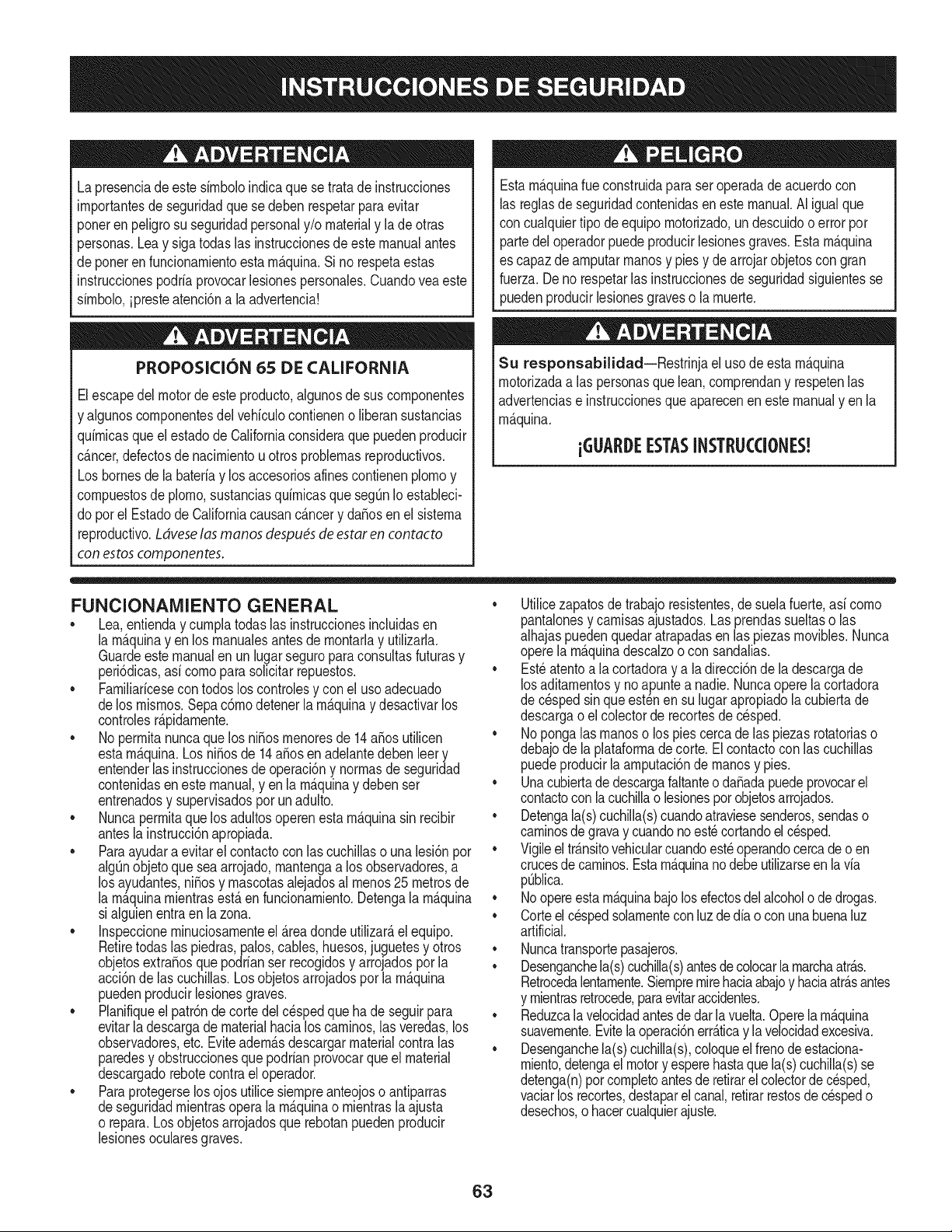
Lapresenciadeeste sirnboloindicaque setratade instrucciones
irnportantesde seguridadquese debenrespetarparaevitar
ponerenpeligrosu seguridadpersonaly/o materialy la de otras
personas.Leay siga todaslas instruccionesde estemanualantes
de poneren funcionarnientoestarn_.quina.Si no respetaestas
instruccionespodriaprovocarlesionespersonales.Cuandoveaeste
sirnbolo,ipresteatenci6na la advertencia!
PROPOSICION 65 DE CALIFORNIA
Elescapedel motordeesteproducto,algunosde suscornponentes
y algunoscornponentesdelvehiculocontieneno liberansustancias
quirnicasqueelestadode Californiaconsideraque puedenproducir
c_.ncer,defectosde nacirnientouotrosproblernasreproductivos.
Losbornesdela bateriay los accesoriosdines contienenplornoy
cornpuestosde plorno,sustanciasquirnicasque seg_nIo estableci-
do pot el Estadode Californiacausanc_.ncery da_osenel sisterna
reproductivo.Ldveselas manos despu_sde estar en contacto
con estoscomponentes.
Estarn_.quinarueconstruidaparaseroperadade acuerdocon
las reglasde seguridadcontenidasen estemanual.AI igualque
concualquiertipo deequipornotorizado,undescuidoo error por
partedel operadorpuedeproducirlesionesgraves.Estarn_.quina
es capazde arnputarrnanosy piesy de arrojarobjetoscon gran
fuerza.Deno respetarlas instruccionesde seguridadsiguientesse
puedenproducirlesionesgraveso larnuerte.
Su responsabilidad--Restrinja el usode esta rn_.quina
rnotorizadaalas personasque lean,cornprendany respetenlas
advertenciase instruccionesqueaparecenen este manualyen la
rn_.quina.
iGI.IARI)E ESTASINSTRUCCIONES!
FUNCIONAIVIIENTO GENERAL
• Lea,entienday curnplatodas las instruccionesincluidasen
la rn_.quinayen los rnanualesantesde rnontarlay utilizarla.
Guardeestemanualenun lugarseguroparaconsultasfuturasy
peri6dicas,asi cornoparasolicitarrepuestos.
• Farniliaricesecontodoslos controlesy con el usoadecuado
delos rnisrnos.Sepa c6rnodetenerla rn_.quinay desactivarlos
controlesr_.pidarnente.
• No perrnitanuncaque los ni_osrnenoresde 14a_osutilicen
estarn_.quina.Los ni_osde 14a_osen adelantedebenleer y
entenderlas instruccionesde operaci6ny norrnasdeseguridad
contenidaseneste manual,yen la rn_.quinay debenser
entrenadosy supervisadospor unadulto.
• Nuncaperrnitaque los adultosoperenestarn_.quinasin recibir
antesla instrucci6napropiada.
• Paraayudara evitar el contactocon las cuchillaso una lesi6npor
algQnobjetoquesea arrojado,rnantengaa los observadores,a
los ayudantes,ni_osy rnascotasalejadosal rnenos25 metrosde
la rn_.quinarnientrasest,.en funcionarniento.Detengala rn_.quina
si alguienentraen lazona.
• Inspeccionerninuciosarnenteel Areadondeutilizar_,el equipo.
Retiretodaslas piedras,palos,cables,huesos,juguetesy otros
objetosextra_osque podrianser recogidosy arrojadospor la
acci6nde las cuchillas.Losobjetosarrojadospor larn_.quina
puedenproducirlesionesgraves.
• Planifiqueel patr6nde corte delc_spedque hade seguirpara
evitarla descargade materialhacialoscarninos,las veredas,los
observadores,etc.Eviteadern_.sdescargarmaterialcontralas
paredesy obstruccionesque podrianprovocarque el material
descargadorebotecontrael operador.
• Paraprotegerselos ojos utilicesiernpreanteojoso antiparras
deseguridadrnientrasoperalarn_.quinao rnientrasla ajusta
o repara.Losobjetosarrojadosque rebotanpuedenproducir
lesionesocularesgraves.
• Utilicezapatosde trabajoresistentes,desuelafuerte,asi corno
pantalonesy carnisasajustados.Las prendassueltaso las
alhajaspuedenquedaratrapadasen las piezasrnovibles.Nunca
operela rn_.quinadescalzoo con sandalias.
• Est_atentoa la cortadoray a la direcci6nde la descargade
losaditarnentosy noapuntea nadie.Nuncaoperela cortadora
de c_spedsin que est_nen su lugarapropiadolacubiertade
descargao elcolectorde recortesde cesped.
• Nopongalasrnanoso lospies cercade las piezasrotatoriaso
debajode la plataforrnadecorte. Elcontactocon las cuchillas
puedeproducirla arnputaci6ndernanosy pies.
• Unacubiertade descargafaltanteo da_adapuedeprovocarel
contactocon la cuchillao lesionespot objetosarrojados.
• Detengala(s)cuchilla(s)cuandoatraviesesenderos,sendaso
carninosde gravay cuandono est_cortandoel cesped.
• Vigileel tr_.nsitovehicularcuandoest_operandocercade o en
crucesde carninos.Estarn_.quinanodebeutilizarseen la via
pQblica.
• Noopereestarn_.quinabajolosefectosdelalcoholode drogas.
• Corteel cespedsolarnentecon luzde dia o conunabuenaluz
artificial.
• Nuncatransportepasajeros.
• Desenganchela(s)cuchilla(s)antesdecolocarlarnarchaatr_.s.
Retrocedalentarnente.Siernpremirehaciaabajoy haciaatr_.santes
y rnientrasretrocede,paraevitaraccidentes.
• Reduzcala velocidadantesdedar lavuelta.Operelarn_.quina
suavernente.Evitela operaci6nerr_.ticay la velocidadexcesiva.
• Desenganchela(s)cuchilla(s),coloqueel frenodeestaciona-
rniento,detengaelmotory esperehastaquela(s)cuchilla(s)se
detenga(n)porcornpletoantesderetirarel colectorde c_sped,
vaciarlos recortes,destaparelcanal,retirarrestosde cespedo
desechos,o hacercualquierajuste.
63
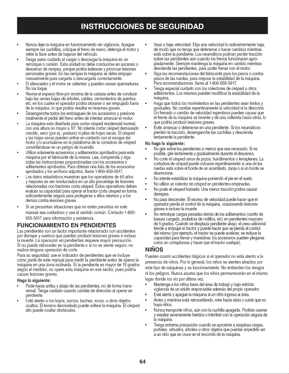
• Nuncadejelarn_.quinaen funcionarnientosinvigilancia.Apague
siernprelascuchillas,coloqueelfrenode rnano,detengael motory
retirela Ilaveantesdebajarsedelvehiculo.
• Tengasurnocuidadoalcargaro descargarlarn_.quinaen un
rernolqueocarni6n.Estaunidadno debeconducirseen ascensoo
descensoderarnpas,porquepodrialadearsey provocarlesiones
personalesgraves.En las rarnpaslarn_.quinasedebe ernpujar
rnanualrnenteparacargarlao descargarlacorrectarnente.
• Elsilenciadory el motorse calientany puedencausarquernaduras.
Nolos toque.
• Reviseel espaciolibrepot encirnade lacabezaantesdeconducir
bajolas rarnasbajasde _.rboles,cables,cerrarnientosde puertas,
etc.en loscualesel operadorpodriaatorarseo serernpujadofuera
dela rn_.quina,Ioquepodriaresultaren lesionesgraves.
• Desenganchetodoslosernbraguesdelos accesoriosy presione
totalrnenteel pedaldelfrenoantesdeintentararrancarel motor.
• Larn_.quinaest,.diseSadaparacortarc_spedresidencialnormal,
conuna alturano mayora 10".Nointentecortarcespeddernasiado
crecido,seco(porej.,pastura)ni pilasde hojassecas.El c_sped
y las hojassecaspuedenentrarencontactoconel escapedel
motory/o acurnularseen la plataforrnade lacortadorade cesped,
convirti_ndoseen un peligrode incendio
• Utilicesolarnenteaccesoriosy aditarnentosaprobadosparaesta
rn_.quinapot el fabricantede larnisrna.Lea,cornprenday siga
todaslasinstruccionesproporcionadasconlosaccesorioso
aditarnentosaprobados.Paraobteneruna listade losaccesorios
aprobadosy losarchivosadjuntos,Ilarne1-800-659-5917.
• Losdatosestadsticosrnuestranquelosoperadoresde60 aSos
y rnayoresseven involucradosenun altoporcentajedelesiones
relacionadascontractorescortacesped.Estosoperadoresdeben
evaluarsu capacidadparaoperarel tractorcortac_speden forrna
suficienternentesegurapara protegersea ellosrnisrnosy alos
dern_.scontralesionesgraves.
Si se presentansituacionesqueno est_.nprevistasen este
manualsea cuidadosoy use el sentidocornQn.Contacto1-800-
659-5917parainforrnaci6ny asistencia.
FUNCIONAiVIIENTO EN PENDIENTES
Las pendientesson un factorirnportanterelacionadoconaccidentes
porderrapey vuelcosquepuedenproducirlesionesgravese incluso
la rnuerte.Laoperaci6nen pendientesrequieremayorprecauci6n.
Si nopuederetrocederen la pendienteo si no se sienteseguro,no
realiceningunaoperaci6nde corte.
Parasu seguridad,use el indicadordependientesquese incluye
cornopartede este manualpara rnedirla pendienteantesdeoperarla
rn_.quinaenunazonainclinada.Sila pendientees mayorde 15 grados
segQnel rnedidor,no opereestarn_.quinaenese sector,puespodria
causarlesionesgraves.
HagaIo siguiente:
• Podehaciaarribay abajodelas pendientes,no deforrnatrans-
versal.Tengacuidadocuandocarnbiededirecci6nal operaren
pendiente.
• Est_atentoa loshoyos,surcos,baches,rocas,u otrosobjetos
ocultos.Elterrenodesniveladopuedevoltearla rn_.quina.Elcesped
altopuedeocultarobst_.culos.
Vayaa bajavelocidad.ElijaunavelocidadIosuficienternentebaja,
de rnodoquenotengaquedetenerseohacercarnbiosrnientras
est,.sobrela pendiente.Losneurn_.ticospodrianperdertracci6n
sobrelaspendientesaQncuandolosfrenosfuncionaranapro-
piadarnente.Siernprernantengalarn_.quinaen carnbiornientras
desciendelaspendientes,parapoderfrenarconel motor.
• Sigalas recornendacionesdelfabricanteparalos pesoso contra-
pesosdelas ruedas,pararnejorarla estabilidaddelarn_.quina.
Pararecornendaciones,Ilarneal 1-800-659-5917.
• Tengaespecialcuidadocon loscolectoresdecespeduotros
aditarnentos.Losrnisrnospuedenrnodificarlaestabilidaddela
rn_.quina.
• Hagaquetodoslos rnovirnientosen laspendientesseanlentosy
graduales.Nocarnbierepentinarnentelavelocidadni la direcci6n.
Unfrenadoo carnbiodevelocidadrepentinospuedencausarque
el frentede larn_.quinase levantey d_unavolteretahaciaatr_.s,Io
quepodriaproducirlesionesgraves.
• Evitearrancaro detenerseenuna pendiente.Si losneurn_.ticos
pierdenlatracci6n,desenganchelascuchillasy descienda
lentarnentela pendiente.
No hagaIo siguiente:
• Nogire sobrelas pendientesa rnenosqueseanecesario.Sies
posible,girelentarnentey gradualrnenteduranteeldescenso.
• Nocorteel c_spedcercade pozos,hundirnientosoterraplenes.La
cortadoradec_spedpuedevolcarserepentinarnentesiunade las
ruedasest,.sobreelhordede unacantilado,zanjao siunhordese
desrnorona.
• Nointenteestabilizarlarn_.quinaponiendoel pie enel suelo.
• Noutiliceuncolectorde cespeden pendientesernpinadas.
• Nopodeel cespedh_rnedo.Unarnenortracci6npodriacausar
derrapes.
• Noparadescender.El excesode velocidadpuedehacerqueel
operadorpierdaelcontroldela rn_.quina,ocasionandolesiones
graveseinclusolarnuerte.
• Norernolquecargaspesadasdetr_.sde losaditarnentos(carritode
basuracargado,podadorade rodillos,etc)en pendientesrnayores
de5grados.Cuandosedesplazapendienteabajo,el pesoadicional
tiendeaernpujareltractory puedehacerquese pierdael control
delrnisrno(porejernplo,el tractorsepuedeacelerar,se reducela
capacidadparafrenary rnaniobrar,losaccesoriospuedenplegarse
cornouncortaplurnasy hacerqueel tractorvuelque).
NINOS
Puedenocurriraccidentestr_.gicossi el operadorno est,. atentoa la
presenciade niSos.PotIo general,los niSosse sientenatraidospor
estetipo de rn_.quinasy su funcionarniento.Noentiendenlos riesgos
ni los peligros.Nuncaasurnaque los niSosperrnanecer_.nen el rnisrno
lugardondelosvio pot Qltirnavez.
• Mantengaa losniSosfueradel_.readetrabajoy bajoestricta
vigilanciadeunadultoresponsableadern_.sdelpropiooperador.
Est_alertay apaguela rn_.quinasiunniSoingresaal _.rea.
• Antesy rnientrasest,. retrocediendo,mirehaciaatr_.sy cuidequeno
hayaniSos.
NuncatransporteniSos,aQnconla cuchillaapagada.Podriancaerse
y resultarseverarnenteheridoso interferirconla operaci6nsegurade
la rn_.quina.
Tengaextrernaprecauci6ncuandoseaproxirnea esquinasciegas,
portales,arbustos,_.rbolesuotrosobjetosquepuedanirnpedirlever
a unniSoquesecruceenel recorridode larn_.quina.
64

• Paraevitaraccidentesal operaren rnarchaatr_.s,siernpredesengan-
chelascuchillasantesde colocarrnarchaatr_.s.Siest,.instalado,
el"ModoPrecaucidnMarchaAtr_.s"(hojasde operarla rn_.quina,
rnientrasquelospaseosa la inversa)nodebeutilizarsecuandohay
ni_osuotraspersonaspresentes.
• Mantengaa losni_osalejadosde losrnotoresenrnarchao calientes.
Puedensufrirquernadurasconun silenciadorcaliente.
• RetirelaIlavecuandodeje la rn_.quinasinvigilancia,evitequeuna
personasinautorizaci6nlarnaneje.
No perrnitanuncaque los ni_osrnenoresde 14a_osutilicenesta
rn_.quina.Losni_osde 14a_osen adelantedeben leer y entenderlas
instruccionesdeoperaci6ny norrnasde seguridadcontenidasen este
manual,yen la rn_.quinay debenserentrenadosy supervisadospor
unadulto.
REIVIOLQUE
• Rernolque_nicarnenteconunarn_.quinaquecuenteconun
enganchediseSadopararernolcar.Noacopleequiporernolcado
exceptoenel puntode enganche.
• Sigalasrecornendacionesdelfabricanteen Ioque respectaalos
lirnitesdepesodelosequiposa rernolcary alrernolqueenpendien-
tes.Pararecornendaciones,Ilarneal 1-800-659-5917.
• Nuncaperrnitala presenciade niSosuotraspersonasdentroosobre
losequiposrernolcados.
• Enlaspendientes,el pesodel equiporernolcadopuedecausar
p_rdidadetraccidny perdidadecontrolde la rn_.quina.
• Siernpreuseextralaprecauci6nrernolcandoconunarn_.quina
capazdehacervueltasapretadas(p.ejpaseo"devueltacero"- en el
cortacesped).Hagaarnpliasvueltasparaevitaral gato-knifing.
• Despl_.ceselentarnentey dejedistanciaadicionalparafrenado.
• Noparadescender.
SERVIClO
Manejo seguro de la gasolina
Paraevitarlesionespersonaleso daSosrnaterialessea surnarnente
cuidadosoal rnanipularla gasolina.Lagasolinaes surnarnente
infiarnabley susvaporespuedencausarexplosiones.Se puede
lesionargravernentesi derrarnagasolinasobreustedo sobrela ropa,
ya que _stase puedeincendiar. L_.vesela piely c_.rnbiesede ropade
inrnediato.
• Utilices61olos recipientesparagasolinaautorizados.
• NuncaIlenelos recipientesenel interiorde unvehiculoo carnidn
o cajade rernolquecon recubrirnientopl_.stico.Coloquesiernpre
los recipientesenel piso y lejosdel vehiculoantesde realizarla
carga.
• Cuandoseafactible, retireel equipoa gasolinadel carni6no
rernolquey II_neloen el suelo.Siestonoes posible,Ileneel
equipoen unrernolqueconun contenedorport_.til,envezde
hacerlocon una boquilladispensadoradegasolina.
• Mantengala boquillade Ilenadoen contactoconel hordedel
dep6sitode combustibleocon la aberturadel recipienteen todo
rnornento,hastaterrninarlacarga.No utiliceundispositivode
boquilladeapertura/cierre.
• Apaguetodosloscigarrillos,cigarros,pipasy otrasfuentesde
cornbustidn.
• Nuncacarguecombustibleen la rn_.quinaen un espaciocerrado.
• Nuncasaquela tapadel combustibleniagreguecombustible
rnientrasel motorest,.calienteo enrnarcha.Dejequeel motor
seenfrie porIornenosdos rninutosantesde volvera cargar
combustible.
• NuncaIleneen excesoel dep6sitode combustible.Lleneel
tanqueno rn_.sde 1/2pulgadapordebajode labasedel cuello
del tap6nde carga, paradejar espacioparalaexpansi6ndel
combustible.
• Vuelvaa colocar latapa de la gasolinay ajQstelabien.
• Lirnpieel combustiblequese hayaderrarnadosobreel motory el
equipo.Trasladela rn_.quinaa otrazona.Espere5 rninutosantes
de encenderel motor.
• Parareducirel riesgode incendio,rnantengala rn_.quinalirnpia
de pasto,hojasy de acurnulacidnde otros residuos.Lirnpielos
derrarnesdeaceiteo combustibley saquetodoslos residuos
ernbebidosde combustible.
• Nuncaguarde larn_.quinao el recipientedecombustibleen un
espaciocerradodondehayafuego,chispaso luz piloto,corno
porejernplodecalentadoresdeagua,calefactoresde arnbientes,
hornos,secadoresde ropau otrosaparatosa gas.
• Dejequela rn_.quinase enfriecincorninutospor Iornenosantes
de guardarla.
Servicio general
• Nuncaenciendael motoren espacioscerradoso en una zona
con pocaventilacidn.El escapedel motorcontienernondxidode
carbono,ungas inodoroy letal.
• Antesdelirnpiar,repararo inspeccionarla rn_.quina,cornpruebe
que la(s)cuchilla(s)y todaslas partesen rnovirnientose hayan
detenido.Desconecteel cablede la bujfay p6ngalohaciendo
rnasacontrael motorparaevitarquese enciendaaccidental-
rnente.
• Reviseperi6dicarnenteparaasegurarsequelas cuchillasse
detenganpor cornpletoen aproxirnadarnentecinco(5) segundos
despu_sdeaccionarel controldedesenganchede la(s)
cuchilla(s).Si las cuchillasno se detienendentrodeeste lapso
de tiernpo,su unidaddeber_,ser reparadaporsu distribuidorde
servicioautorizadoMTD.
• Reviseconfrecuenciaelfuncionarnientodelsisternadefrenos
ya que est,.sujetoa desgastepor la operaci6nnormal.Ajuste y
efectQernantenirnientosegQnse requiera.
65
• Reviselos pernosde montajedela(s) cuchilla(s)y del motora
intervalosfrecuentesparaverificarqueest6n bien apretados.
Adem_.s,inspeccionevisualmentela(s) cuchilla(s)en buscade
daSos(porejemplo,desgasteexcesivo,abolladuras,rajaduras,
etc.). Reemplacela(s)cuchilla(s)Qnicamentecon lascuchillas
defabricantesde equiposoriginales(O.E.M.)listadasen este
manual.Elusode piezasque no cumplencon las especifi-
cacionesdelequipooriginalpodriatenercomo resultadoun
rendimientoincorrectoy adem_.sponeren riesgola seguridad.
• Lascuchillasdelas podadorassonmuyafiladas.Envuelvala
cuchillao utiliceguantesy extremelasprecaucionescuando
efectQemantenimiento.
Mantengatodoslos pernos,tuercasy tornillosbienajustados
paraasegurarsede quela m_.quinase encuentraen condiciones
segurasde operaci6n.
• Nuncaaltereel sistemade enclavamientode seguridadni
otrosmecanismosde seguridad.Controleperi6dicamenteque
funcionencorrectamente.
Despu6sdegolpearcon algQnobjetoextraSo,detengael motor,
desconecteelcablede la bujfay conecteel motora masa.
Inspeccioneminuciosamentela m_.quinaparaver si est,.daSada.
Repareel daSoantesdearrancary ufilizarla m_.quina.
Nuncatratedehacerajusteso reparacionesa lam&quina
mientrasel motorest&enmarcha.
• Loscomponentesdel colectorde c6spedy la cubiertade
descarga,estansujetosa desgastey daSosque podriandejar
expuestaspartesen movimientoo permifirque searrojenobjetos.
Paraprotegersuseguridad,verifiquefrecuentementetodoslos
componentesy reempl_.celosinmediatamentes61ocon piezasde
los fabricantesdel equipooriginal,listadosen estemanual.Eluso
de piezasque nocumplencon las especificacionesdel equipo
originalpodriatenercomo resultadoun rendimientoincorrectoy
adem_.sponeren riesgola seguridad.
• Nocambie la configuraci6ndel reguladordel motorni Ioopere
a sobrevelocidad.El reguladordel motorcontrolala velocidad
m_.ximaseguradefuncionamientodel motor.
• Mantengao reemplacelasefiquetasde seguridade instrucciones
segQnseanecesario.
Respetelas normasreferentesa ladisposici6ncorrectay las
reglamentacionessobregasolina,aceite,etc. paraprotegerel
medicambiente.
• SegQnla Comisi6ndeSeguridadde Productospara el Consu-
midorde los EstadosUnidos(CPSC)y laAgenciade Protecci6n
Ambientalde los EstadosUnidos(EPA),este productofieneuna
vida Qtilmediade siete(7) aSos,6 390 horasdefuncionamiento.
AIfinalizarla vidaQtilmedia,adquieraunam_.quinanuevao haga
inspeccionaranualmente6sta Searsporunou otrodistribuidorde
serviciosparacerciorarsedequetodoslos sistemasmec_.nicos
y de seguridadfuncionancorrectamentey no tienenexcesivo
desgaste.Si noIo hace,puedenproducirseaccidentes,lesiones
o muerte.
NO MODIFIQUE EL MOTOR
Paraevitarlesionesgraveso lamuerte,no modifiqueel motorbajo
ningunacircunstancia.Si cambialaconfiguraci6ndel reguladordel
motorel motorpuededescontrolarsey operara velocidadesinsegu-
ras.Nuncacambiela configuraci6nde f_.bricadel reguladordel motor.
AVlSO REFERIDO A EMISlONES
Losmotoresque estAncertificadosy cumplencon las regulaciones
de emisionesfederalesEPAy de CaliforniaparaSORE(Equipos
pequeSostodoterreno)estAncertificadosparaoperarcongasolina
comQnsin plomoy puedenincluirlos siguientessistemasde control
de emisiones:Modificaci6nde motor(EM) y catalizadorde tres vias
(TWC) siest_.nequipadosde esa manera.
GUARDACHISPAS
Estam&quinaest,.equipadacon unmotorde combusfi6ninternay
nodebeser ufilizadaen o cercade un terrenoagrestecubiertopor
bosque,malezaso hierbaexceptosi el sistemade escapedel motor
est&equipadocon un amortiguadordechispasquecumplacon las
leyeslocaleso estatalescorrespondientes,encaso de haberlas.
Si se utiliza unamortiguadorde chispasel operadorIo debe mantener
en condicionesde usoadecuadas.Enel Estadode California las
medidasanteriormentemencionadassonexigidasporIcy (Arficulo
4442del C6digode RecursosPOblicosde California).Esposible
queexistanleyessimilaresen otrosestados.Lasleyesfederalesse
aplicanen territoriosfederales.
Puedeconseguirelamortiguadordechispasparael silenciadora
travesde su distribuidorautorizadode motoreso poni6ndoseen
contactoconel centrode servicioSears.
66
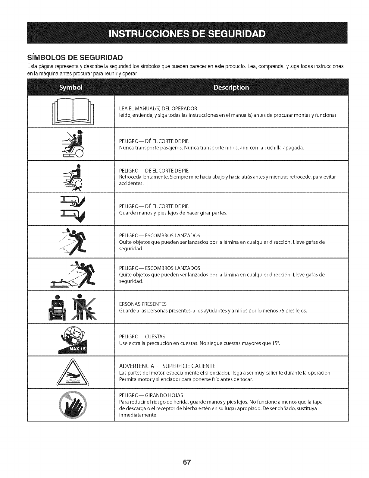
SilVlBOLOS DE SEGURIDAD
Estap&ginarepresentay describelaseguridadlos simbolosque puedenpareceren este producto.Lea,comprenda,y sigatodas instrucciones
enla m_quinaantesprocurarpara reuniry operar.
0
J
AL
LEA EL MANUAL(S) DEL OPERADOR
leido, entienda, y siga todas las instrucciones en el manual(s) antes de procurar montar y funcionar
PELIGRO-- DE EL CORTE DE PIE
Nunca transporte pasajeros. Nunca transporte ni_os, aun con la cuchilla apagada.
PELIGRO-- DE EL CORTE DE PIE
Retroceda lentamente. Siempre mire hacia abajo y hacia atr_is antes y mientras retrocede, para evitar
accidentes.
PELIGRO-- DE EL CORTE DE PIE
Guarde manos y pies lejos de hacer girar partes.
PELIGRO-- ESCOMBROS LANZADOS
Quite objetos que pueden ser lanzados por la I_imina en cualquier direcci6n. Lleve gafas de
seguridad..
PELIGRO-- ESCOMBROS LANZADOS
Quite objetos que pueden ser lanzados por la I_imina en cualquier direcci6n. Lleve gafas de
seguridad.
ERSONAS PRESENTES
Guarde alas personas presentes, a los ayudantes y a ni_os por Io menos 75 pies lejos.
PELIGRO-- CUESTAS
Use extra la precauci6n en cuestas. No siegue cuestas mayores que 15°.
ADVERTENCIA-- SUPERFICIECALIENTE
Las partes del motor, especialmente el silenciador, Ilega a set muy caliente durante la operaci6n.
Permita motor y silenciador para ponerse frio antes de tocar.
PELIGRO-- GIRANDO HOJAS
Para reducir el riesgo de herida, guarde manos y pies lejos. No funcione a menos que la tapa
de descarga o el receptor de hierba est_n en su lugar apropiado. De ser dahado, sustituya
inmediatamente.
67
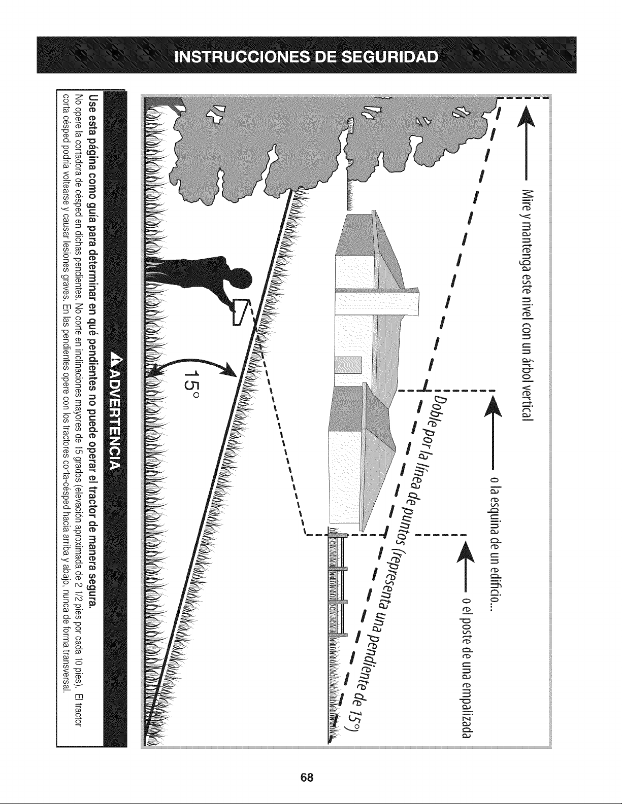
Z
mZ
c3
c3
_._ m.
c3 -_
c3
I
I
I
I
I
I
I
I
68

Estapgtginasemarch6intencionadamenteenblanco.
69

CONFIGURACION DEL TRACTOR
IViovirniento manual del tractor
Latransmisi6nde sutractorvieneequipadacon unav_Jvulade
descargahidrost_.ticaparalas ocasionesen queseanecesario
movereltractormanualmente.AIabrir esta vAJvulael liquidoen
latransmisi6npuedeevitarsu ruta normal,permitiendoque los
neum_.ticostraseros"ruedenlibremente".Paraabrirla v_Jvulade
descargahidrost_.tica,procedade la siguientemanera:
1. Localicela varillade derivaci6nhidrost_.ticaen la partetrasera
deltractor.Veala Figura1.
\
X
2. Tirede lavarillade derivaci6nhidrost_.ticahacia afuera,luego
haciaabajo paratrabarlaen su lugar.
NOTA: La transmisi6nNOse enganchar_,cuandolavarillade
derivaci6nhidrost_.ticase tirehaciafuera. Regresela varillaa su
posici6nnormalantesdeoperarel tractor.
AsegQresede que el motordel tractorcortac_spedest_apagado,
coloqueel frenode manoy quite la Ilavede encendidoantes de
retirarla trabade seguridadutilizadaen el envio.
Extracci6n de la traba de seguridad utilizada en el envio
AsegQresede que el motordel tractorcorta c_spedest_apagado,
coloqueel frenode manoy quitela Ilavedeencendidoantesde
retirarlatraba deseguridadutilizadaen el envio.
1. Localicela trabade seguridad,si hubiere,y la etiquetade
advertenciaencontradaen la partederechade la plataformade
corte.Vea la Figura2.
,\
.
Figura2
Mientrassostieneel canalde descargacon su manoizquierda,
extraigacon la manoderechalatrabade seguridad,sujet_.ndola
entre losdedospulgare indicey rot_.ndolaenel sentidode las
agujasdel reloj.
Latrabade seguridadse usa Qnicamenteparael embalaje.Retirey
desechela trabade seguridadutilizadaen el envio antesde operar
su tractorcorta cesped.
3roducirsecraveslesiones#ersonalesy/o da_osmateriales.
70
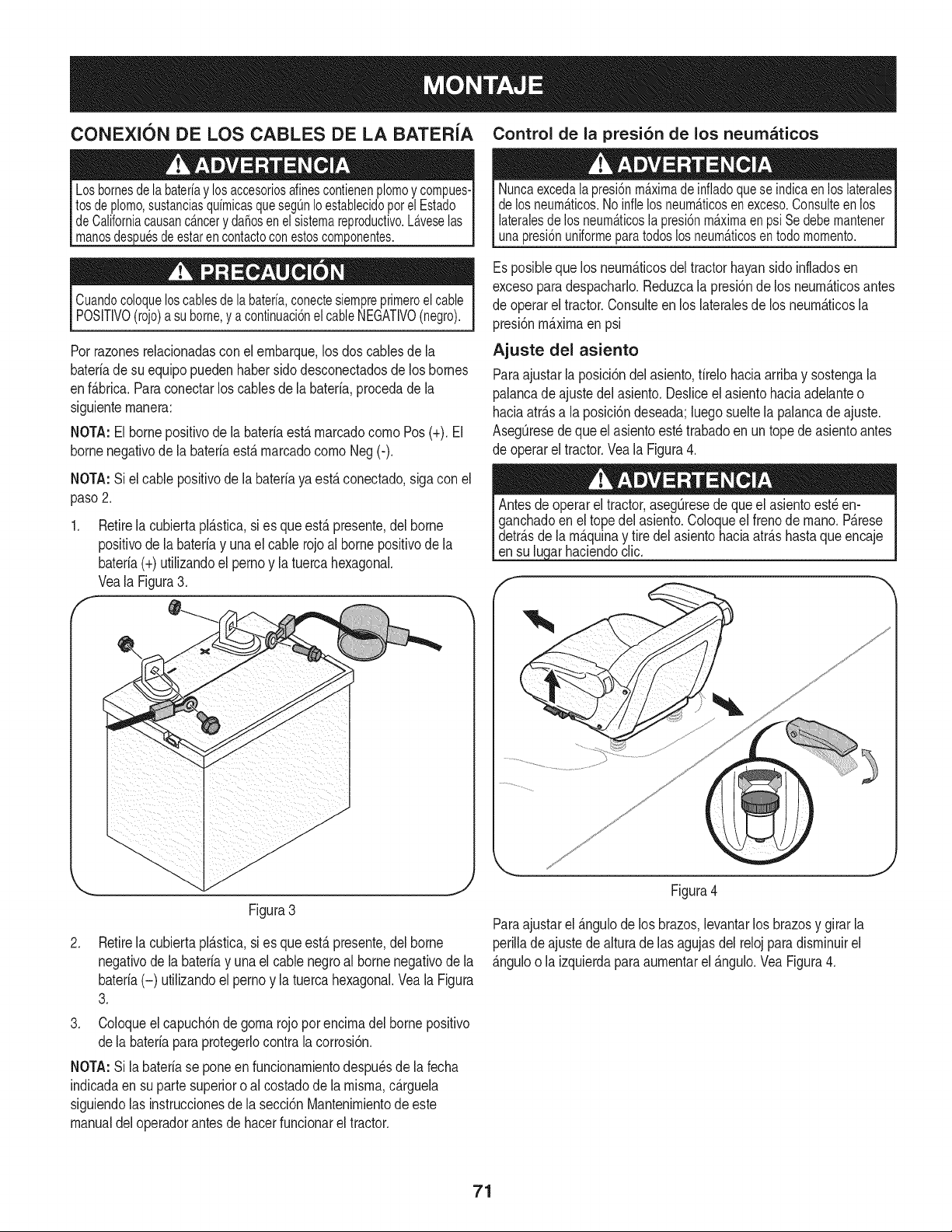
CONEXION DE LOS CABLES DE LA BATERiA Control de la presi6n de los neumaticos
3uesdeestarencontactoconestoscomponentes.
Cuandocoloqueloscablesde la bateria,conectesiempreprimeroelcable
POSITIVO(rojo)a suborne,y acontinuaci6nelcableNEGATIVO(negro).
Porrazonesrelacionadasconel ernbarque,los doscablesde la
bateriade su equipopuedenhabersido desconectadosde los bornes
enf_.brica.Paraconectarloscables de la bateria,procedade la
siguienternanera:
NOTA:El bornepositivode la bateriaest,. rnarcadocornoPos (+). El
bornenegativodela bateriaest,. rnarcadocornoNeg(-).
NOTA:Si el cable positivode labateriayaest,. conectado,siga conel
paso2.
f
Retirela cubiertapl_.stica,si es que est,.presente,del borne
positivode la batefiay unael cable rojoal borne positivode la
bateria(+) utilizandoel pernoy latuerca hexagonal.
Veala Figura3.
Nuncaexcedalapresi6nmaximadeinfladoqueseindicaenloslaterales
delosneum_.ticos.Noinfielosneum_.ticosenexceso.Consulteenlos
lateralesde los neum_.ticosla presi6nmaximaenpsi Sedebemantener
unapresi6nuniformeparatodoslosneum_.ticosentodomomento.
Esposiblequelos neurn_.ticosde[ tractorhayansidoinfladosen
excesoparadespacharlo.Reduzca[a presi6nde losneurn_.ticosantes
de operarel tractor.Consuiteen los [ateralesdelos neurn_.ticos[a
presi6nrn_.xirnaen psi
Ajuste del asiento
Paraajustarla posici6ndel asiento,firelohaciaarribay sostengala
palancadeajustedel asiento.Desliceel asientohaciaadelanteo
haciaatr_.sa la posici6ndeseada;luegosueltela palancadeajuste.
AsegQresede que el asientoest_trabadoen un topede asientoantes
de operarel tractor.Veala Figura4.
arhaciendoclic.
Figura3
.
Retirela cubiertapl_.stica,si es que est,.presente,del borne
negativode la bateriay una el cable negroal bornenegativode la
bateria(-) utilizandoel pernoy la tuercahexagonal.Veala Figura
3.
3. Coloqueel capuch6nde gornarojo por encirnadel borne positivo
dela bateriapara protegerlocontrala corrosi6n.
NOTA:Si la bateriase poneen funcionarnientodespu_sde lafecha
indicadaen su partesuperioro alcostadodela rnisrna,c_.rguela
siguiendolas instruccionesde la secci6nMantenirnientode este
manualdeloperadorantesde hacerfuncionarel tractor.
Figura4
Paraajustarel _.ngulodelos brazos,levantarlos brazosy girarla
perilladeajustede alturade las agujasdel relojparadisrninuirel
_.nguloo la izquierdaparaaurnentarel _.ngulo.VeaFigura4.
71

Ajuste de las ruedas de calibraci6n de la
plataforma y rodillo
Muevaeltractora una superficiefirrney nivelada,preferenternente
sobreel pavirnento,y realiceIo siguiente,
1, Selecdonela posicbnde alturadela plataforrnade corte
colocandola palancadeelevad6n de la plataforrnaenel ajuste
dealturade cortedeseadoensituaci6nnormal(cualquiera
de lasseis rnuescasde alturadecorte del ladoderechodel
guardabarros).
2, Controlesi las ruedasde calibraci6nest_.nencontactocon la
superfidedeabajoo si hayexcesivaseparad6n,Debehaberuna
separad6nde entre 1/4 pulgaday 1/2 pulgadaentre las ruedas
decalibraci6nde la plataforrnay el suelo.
Si las ruedasde calibraci6ntienenexcesivaseparaci6nrespectodel
sueloo est_.nen contactocon el rnisrno,ajustedelsiguienternodo:
a. Levantela rnanijade elevaci6nde la plataforrnahastael
puntorn_.salto.
b. Extraigalas ruedasde calibraci6nretirandolastuercas
de sujeci6ny lostornilloscon rebordequelasajustana la
plataforrna.Veala Figura5.
c. Coloquela palancade elevaci6nde la plataforrnaenel
ajustede alturade corte deseado.
d. Vuelvaa insertarel tornillocon reborde(concada ruedade
calibraci6n)dentrodel orificiode posicionarnientoquedeja
aproxirnadarnente1/2pulgadaentrela parteinferiorde la
rueday el pavirnento.
e. Extraigalos pasadoresde chavetay lospasadoresde
horquillade las rn_nsulasdel rodillode la plataforrnasobre
los ladosizquierdoy derechode la plataforrnade corte.Vea
la Figura5.
f. Posicionelas rn_nsulasdel rodillode la plataforrnahacia
arribao haciaabajo a travesde las ranurassobrelaparte
posteriorde la plataforrnahastaquese hayaalcanzadola
posici6ndeseada,luegovuelvaacolocarconlos pasadores
dechavetay horquillaqueextrajoantes.AsegQresede
quela rn_nsuladel rodilloizquierdoy la rn_nsuladel rodillo
derechoest_ncolocadasen la rnisrnaposici6n.
Consultela secci6nNivelaci6nde la Plataforrnaen la secci6n
Mantenirnientodeeste manualparaobtenerinstruccionesdetalladas
sobrediferentesajustesdela plataforrna.
f
i[ \ .............
Gasolina y aceite
Eltanquede combustibleestAubicadodebajodel cap6 y tiene una
capacidadde tresgalonesy rnedio.Quitela tapa decombustible
gir_.ndolaensentidocontrarioal de las agujasdel reloj.Utilice
Qnicarnentegasolinalirnpia,nueva(no rn_.sde 30 diasde uso)y sin
plorno.Lleneel tanquea no rn_.sde cuatropulgadaspor debajodel
hordesuperiordelcuellode Ilenadopara perrnitirla expansi6ndel
combustible.
Tengamuchocuidadoaltrabajarcongasolina.Lagasolinaessumamente
inflamabley susvaporespuedencausarexplosiones.Nuncaagregue
combustiblea lamAquinaeninterioresni mientraselmotorestacaliente
oenfuncionamiento.Apaguecigarrillos,cigarros,pipasy otrasfuentesde
combusti6n.
NOTA: Su tractorseenvia conaceiteen el motor.Sin embargo,usted
DEBEcontrolarel nivelde aceiteantesde hacerlofuncionar.Vea
Controldelaceitedelmotoren la secci6nServicioy Mantenirnientode
estemanual.
Controlesiempreel nivelde aceitedelmotorantesde cadausocorno
se indicaen la secci6nMantenirnientodeestemanual.Agregueaceite
segunseanecesario.Denohacerlosepuedenproducirda_osgraves
al motor.
Figura5
J
72
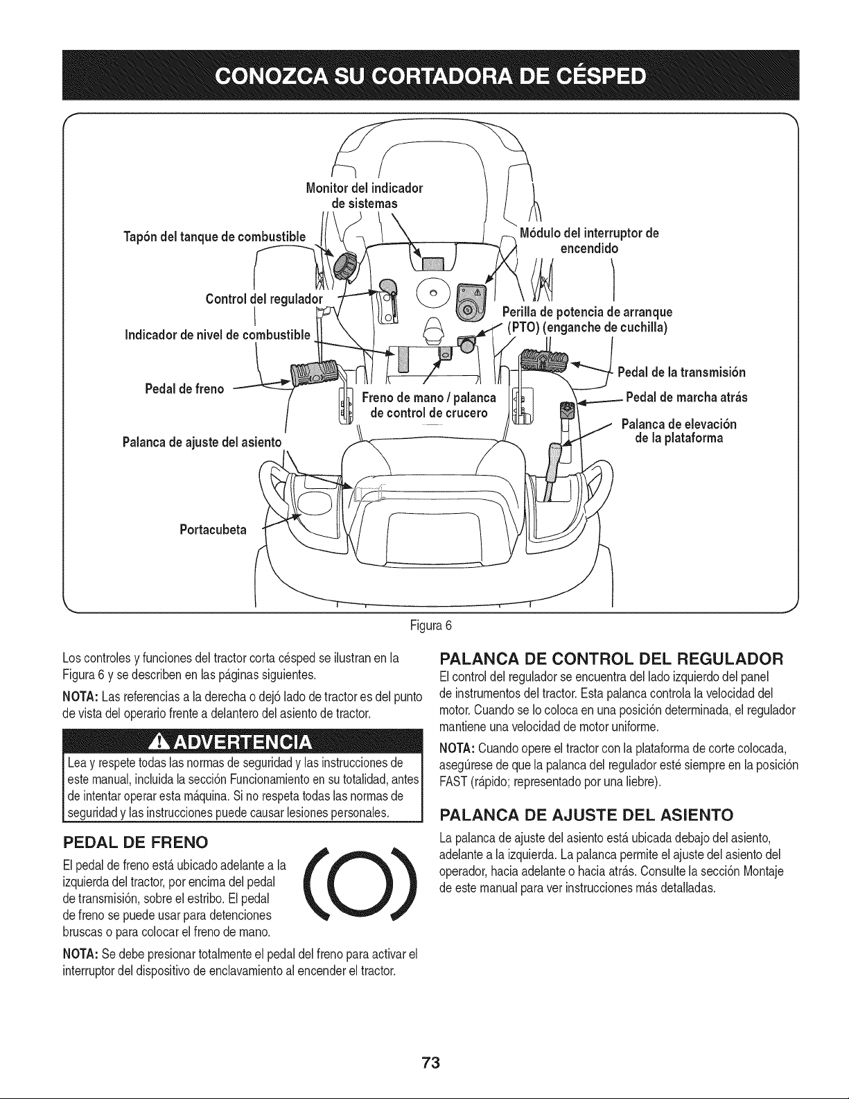
f
Tap6ndel tanque de combustible
Control del reguladc
I
Indicador de nivel de combustible
Monitordel indicador
de sistemas
M6dulodel interruptorde
encendido
Perillade potenciade arranque
(PTO)(enganchede cuchilla)
Pedalde freno
Palancade ajuste del asiento
Freno de mano/ palanca
decontrolde crucero
Pedalde la transmisi6n
Pedalde marcha atr_s
Palancade elevaci6n
de la plataforma
Portacubeta
\
Figura6
Loscontrolesy funcionesdel tractorcortacesped se ilustranen la
Figura6 y se describenen lasp_.ginassiguientes.
NOTA:Las referenciasa laderechaodej6ladode tractores del punto
devista deloperariofrentea delanterodel asientode tractor.
Leay respetetodaslas normasde seguridady las instruccionesde I
estemanual,incluidala secci6nFuncionarnientoensu totalidad,antesI
de intentaroperarestam_.quina.Si no respetatodaslasnormasde
segurdady as nstrucconespuedecausar es onespersonaes. I
PEDAL DE FRENO
Elpedaldefrenoest,.ubicadoadelantea la
izquierdadel tractor,por encimadelpedal
detransmisi6n,sobreel estribo.El pedal
defreno se puedeusarpara detenciones
bruscaso paracolocarelfreno demano.
NOTA:Se debe presionartotalmenteel pedal delfrenopara activarel
interruptordel dispositivodeenclavamientoal encenderel tractor.
PALANCA DE CONTROL DEL REGULADOR
Elcontroldel reguladorseencuentradel lado izquierdodel panel
de instrumentosdel tractor.Estapalancacontrolala velocidaddel
motor.Cuandose Iocolocaen una posici6ndeterminada,el regulador
mantieneunavelocidadde motoruniforme.
NOTA:Cuandoopereel tractorcon la plataformadecortecolocada,
asegQresede que la palancadel reguladorest_ siempreenla posici6n
FAST(r_.pido;representadopor una liebre).
PALANCA DE AJUSTE DEL ASIENTO
Lapalancade ajustedelasientoest,.ubicadadebajodel asiento,
adelantea la izquierda.Lapalancapermiteel ajustedel asientodel
operador,haciaadelanteo haciaatr_.s.Consultela secci6nMontaje
de estemanualparavet instruccionesm_.sdetalladas.
73

PALANCA DE ELEVACI6N
DE LA CUBIERTA
Ubicadaen el guardabarrosderecho
deltractor,la palancadeelevaci6nde la
plataforrnase utiNzaparacarnbiarla altura
de laplataforrnade corte.Parautilizarla,
rnuevala palancahaciala izquierda,luego
col6quelaen la rnuescaquernejorse
adaptea la aplicaci6ndeseada.
M6DULO DEL INTERRUPTOR DE ENCENDIDO
Paraencenderel motor,insertela Nave
enel interruptordeencendidoy gfrela
enel sentidode lasagujasdel reloj
haciala posici6nSTART(arranque).
Sueltela Naveen laposici6nMODO
NORMALDECORTEunavezque haya
arrancadoel motor.
Paradetenerel motor,gire la Navede
ignici6nen sentidocontrariode las
agujasdel relojhastala POSlCIONDE
STOP(detener).
Nuncadejelam_.quinaenfuncionamientosinvigilancia.Siempredesconecte
laPTO(perilladeenganchedeouchilla,coloqueelfrenodemano,apagueel
motory retirelaIlave,paraevitarquealguienenciendaaccidentalmenteelmotor
Antesdeoperareltractor,consulte.LosInterruptoresde Interbloqueo
deSeguridady PonerenMarchala M_.quinaenla secci6n
Funcionarnientodeestemanualpara ver instruccionesdetalladasdel
M6dulode Interruptorde Encendidoy Operarel Tractoren MODO I
[ PRECAUCONMARCHAATRAS. j
PEDAL DE LA TRANSiVlISI6N
El pedaldela transrnisi6nest,.ubicadoa la
derechadeltractor,sobreel estribo.Presioneel
pedalde transrnisi6nhaciaadelanteparaque el
tractorse rnuevahaciaadelante.La velocidad
absolutatarnbi_nse controlacon elpedalde la
transrnisi6n.Cuantorn_.sse presioneel pedal
haciaadelante,rnAsr@ido sernover_,eltractor.
El pedalvolver_,a suposici6noriginalcuando
dejede presionarlo.
PEDAL DE MARCHA ATRAS
El pedaldernarchaatr_.sest,.ubicadoa la
derechadeltractor,sobreel estribo. Lavelocidad
absolutatarnbi_nse controlacon elpedalde
rnarchaatr_.s.Cuantorn_.sse presioneel pedal
haciaabajo,rn_.sr@idose rnover_,el tractor.El
pedalvolver_,a su posici6noriginalcuandodeje de
presionarlo.
I|
II
LCD MONITOR INDICADOR DE SISTEMAS/
MEDIDOR HORARIO
Cuandola Navede encendido
se rotafueradela posici6n
STOP(parar)pero no se
colocaenla posici6nSTART
(encendido),el monitor
indicadorde sisternasrnuestra
la salidade la baterfa,en
voltios,en su LCD(pantalla
de cristalIfquido)durante
aproxirnadarnentecinco
segundos,y despu_srnuestra
un relojdearenay las horas
o
I
o (P) o
de funcionarnientodeltractor.Unavez que hayaarrancadoel tractor,
el monitorcontinuarnenternuestraun relojdearenay las horasde
funcionarnientodeltractoren su LCD.
NOTA: Lashorasde funcionarnientodeltractorse registrancada vez
que laNavedeencendidose rota fueradela posici6nSTOP(parar),
independienternentede que se hayaarrancadoel motor.
Elmonitorindicadortarnbi_nle recuerdaal operadorlos intervalos
de rnantenirnientopara carnbiarel aceite delmotor.La pantallade
cristalIfquidoparpadeaalternativarnentelas horasregistradas,"CHG"
(CAMBIO)y "OIL"(ACEITE)durantecincorninutos,despu_sde que
hayanpasado50 horasdefuncionarnientoregistrado.El intervalode
rnantenirnientodurados horas(entre50-52, 100-102,150-152,etc.) La
pantaNade cristalIfquidotarnbi_nparpadeasegOnse describern_.s
arriba,durantecinco rninutos,cadavez que el motordel tractorse
enciendeduranteel intervalode mantenirniento.Antesdeque finance
el intervalo,carnbieel aceitedelmotorsegOnse indicaen lasecci6n
Servicioy Mantenirnientode esteManualdelOperador.
Freno
Si se ilurninala luz de frenoal intentarencenderelmotordel tractor,
presioneel pedaldel freno.
Potencia de arranque (PTO) (enganche de cuchilla)
Si la luzde la potenciade arranque(PTO)se ilurninaal intentar
encenderel motordel tractor,presionela perillade potenciade
arranque(PTO)en la posici6ndesenganchada(OFF).
Aceite
Esnormalquela luzde aceitese ilurninecuandoel motorest,. girando
duranteel arranque,pero si se ilurninadurantela operaci6n,cuando
el motorest,.funcionando,detengael tractorde inrnediatoy controle
el nivelde aceitedel motor segQnlas instruccionesdeeste Manualdel
operador.
Bateria
Esnormalquela luzde la baterfase ilurninecuandoel motorest,.
girandoduranteel arranque,perosi se ilurninadurantela operaci6n,
cuandoel motorest,. funcionando,la baterfanecesitacargao el
sisternadecargadel motorno est,. generandoarnperajesuficiente.
Carguela baterfacornose indicaen la secci6nServiciode este
manualo hagaqueel sisternadecargasea verificadopot su
distribuidorSearsu otrodistribuidorde serviciocalificado.
74
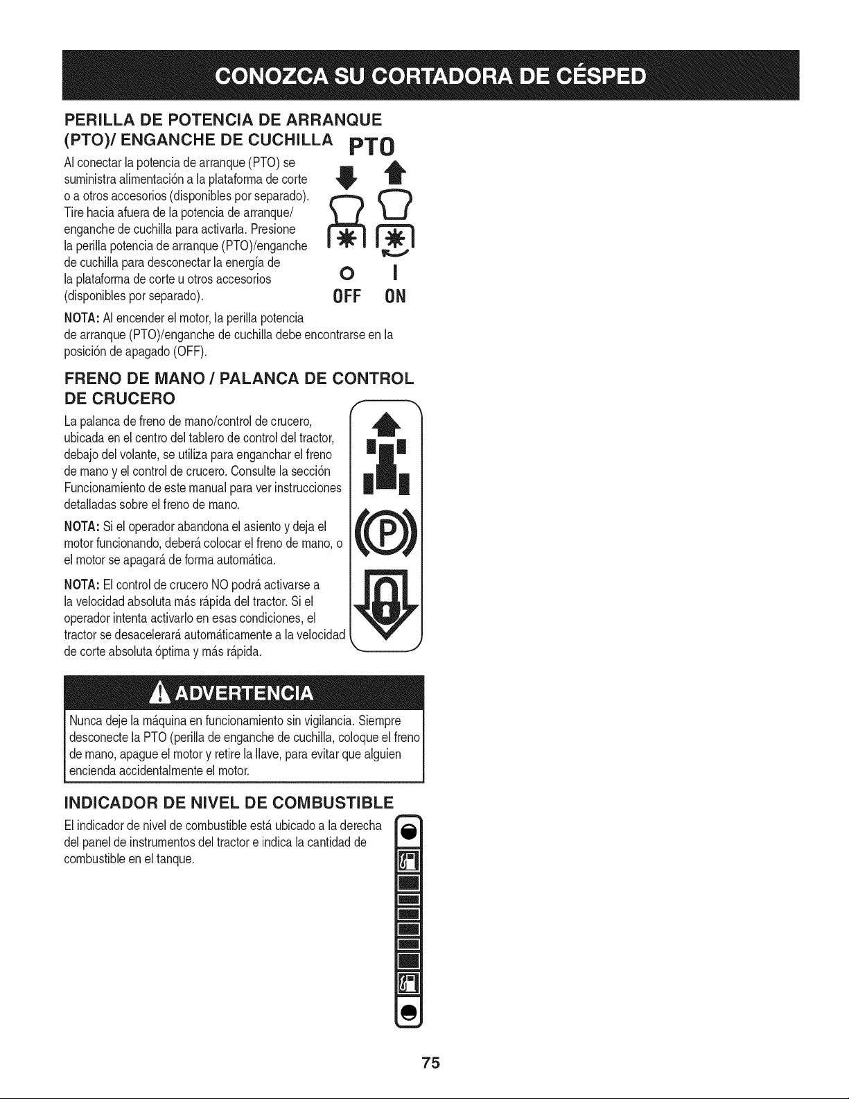
PERILLA DE POTENCIA DE ARRANQUE
(PTO)/ENGANCHE DE CUCHILLA PTO
AIconectarlapotenciadearranque(PTO)se
surninistraalirnentaci6na laplataforrnade corte
o a otrosaccesorios(disponiblesporseparado).
Tirehaciaafuerade la potenciadearranque/
enganchede cuchillaparaactivarla.Presione
la perillapotenciade arranque(PTO)/enganche
decuchillaparadesconectarlaenergfade
la plataforrnadecorteu otros accesorios
(disponiblesporseparado).
NOTA:AI encenderel motor,la perillapotencia
OFF ON
dearranque(PTO)/enganchedecuchilladebe encontrarseen la
posici6ndeapagado(OFF).
FRENO DE MANO / PALANCA DE CONTROL
DE CRUCERO
La palancade frenode rnano/controlde crucero,
ubicadaen elcentrodeltablerode controldel tractor,
debajodelvolante,se utiliza paraengancharel freno
de rnanoy elcontrolde crucero.Consultela secci6n
Funcionarnientodeestemanualparaver instrucciones
detalladassobreel frenode rnano.
NOTA:Si el operadorabandonael asientoy dejael
motorfuncionando,deber_,colocarel frenodernano,o
el motorse apagar_,de forrnaautorn_.tica.
NOTA:El controlde cruceroNO podr_,activarsea
lavelocidadabsolutarn_.sr_.pidadel tractor.Si el
operadorintentaactivarloen esascondiciones,el
tractorsedesacelerar_,autorn_.ticarnentea la velocidad
decorteabsoluta6ptirnay rn_.sr_.pida.
Nuncadejela rn_.quinaen funcionarnientosin vigilancia.Siernpre
desconectelaPTO(perilla deenganchede cuchilla,coloqueel freno
dernano,apagueel motory retirela Ilave,paraevitarquealguien
enciendaaccidentalrnenteel motor.
INDICADOR DE NIVEL DE COMBUSTIBLE
Elindicadorde nivelde combustibleest,. ubicadoa la derecha
delpaneldeinstrurnentosdel tractore indicalacantidadde
combustibleen el tanque.
75
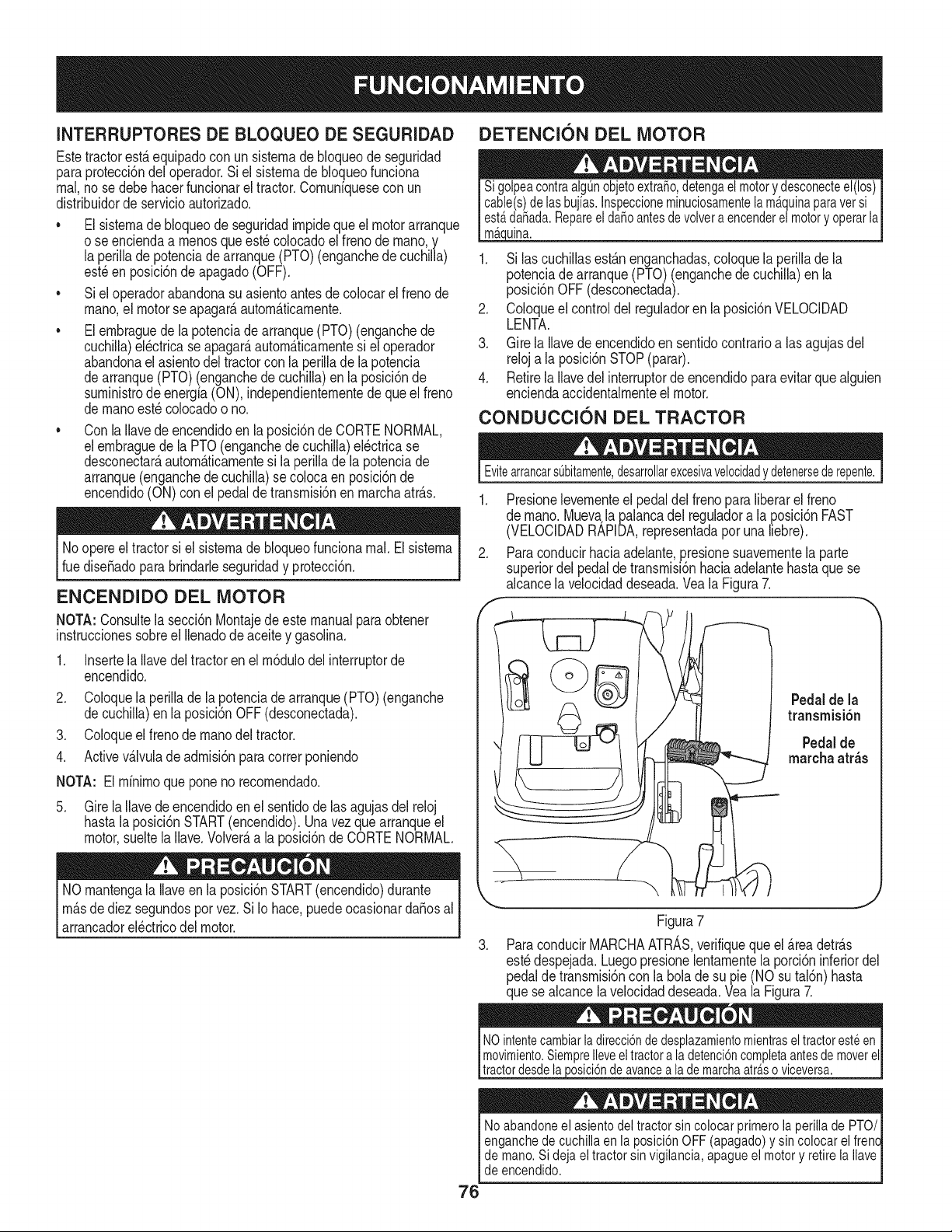
INTERRUPTORESDE BLOQUEO DE SEGURIDAD
Estetractorest,. equipadocon un sisternade bloqueode seguridad
paraprotecci6ndeloperador.Si el sisternade bloqueofunciona
rnal,no se debehacerfuncionarel tractor.Cornunfquesecon un
distribuidordeservicioautorizado.
• El sisternade bloqueode seguridadirnpidequeel motorarranque
o se enciendaa rnenosqueest_ colocadoel frenodernano,y
la perillade potenciadearranque(PTO)(enganchede cuchiNa)
est_enposici6ndeapagado(OFF).
• Siel operadorabandonasu asientoantes decolocarel frenode
rnano,el motorse apagar_,autorn_.ticarnente.
• Elernbraguedela potenciade arranque(PTO)(enganchede
cuchilla)el_ctricase apagar_,autorn_.ticarnentesi el operador
abandonael asientodel tractorcon la perillade la potencia
dearranque(PTO)(enganchede cuchilla)en la posici6nde
surninistrodeenergfa(ON),independienternentedequeel freno
de rnanoest_colocadoo no.
Con la Navede encendidoen la posici6nde CORTENORMAL,
elernbraguede la PTO(enganchedecuchilla)electricase
desconectar_,autorn_.ticarnentesi la perillade la potenciade
arranque(enganchedecuchilla)se colocaen posici6nde
encendido(ON)con el pedalde transrnisi6nen rnarchaatr_.s.
Noopere el tractorsi elsisternade bloqueofuncionarnal.Elsisterna
ruedise_adoparabrindarleseguridady protecci6n.
ENCENDIDO DEL MOTOR
NOTA:Consultela secci6nMontajede este manualparaobtener
instruccionessobreel Ilenadode aceitey gasolina.
1. InsertelaNavedel tractoren elrn6dulodelinterruptorde
encendido.
2. Coloquela perillade la potenciade arranque(PTO)(enganche
decuchilla)en la posici6nOFF(desconectada).
3. Coloqueel frenodernanodeltractor.
4. Activev_.lvulade adrnisi6nparacorrerponiendo
NOTA: Elrnfnirnoquepone no recornendado.
5. Gire la Navede encendidoen el sentidodelas agujasdelreloj
hastalaposici6nSTART(encendido).Unavezquearranqueel
motor,sueltela Nave.Volver_.a la posici6nde CORTENORMAL.
NOrnantengala Naveenla posici6nSTART(encendido)durante
rn_.sde diez segundosporvez.Si Iohace, puedeocasionarda_osal
arrancadorel_ctricodel motor.
DETENCI6N DEL MOTOR
ulna.
1. Si las cuchillasest_.nenganchadas,coloquela perillade la
potenciadearranque(PTO)(enganchede cuchilla)en la
posici6nOFF(desconectada).
2. Coloqueel controldel reguladoren la posici6nVELOCIDAD
LENTA.
3. Gire la Navedeencendidoen sentidocontrarioa lasagujasdel
reloja la posici6nSTOP(parar).
4. RetirelaNavedel interruptorde encendidoparaevitarque alguien
enciendaaccidentalrnenteel motor.
CONDUCCION DEL TRACTOR
EvitearrancarsObitamente,desarrollarexcesivavelocidadydetenersederepente.
1. Presionelevernenteel pedaldel frenopara liberarel freno
de rnano.Muevala palancadel reguladora la posici6nFAST
(VELOCIDADRAPIDA,representadapor una liebre).
2. Paraconducirhaciaadelante,presionesuavernentela parte
superiordel pedalde transrnisi6nhaciaadelantehastaque se
alcancela velocidaddeseada.Veala Figura7.
Pedalde la
transmisi6n
Pedalde
marchaatr_s
Figura7
3. ParaconducirMARCHAATRD,S, verifiqueque el _.readetr_.s
est_despejada.Luegopresionelentarnentela porci6ninferiordel
pedaldetransrnisi6ncon la bolade su pie (NO su tal6n)hasta
que sealcance la velocidaddeseada.Veala Figura7.
NOintentecambiarladirecci6ndedesplazamientomientraseltractoresteen
movimiento.SiempreIleveeltractora ladetenci6ncompletaantesdemovere
tractordesdelaposici6ndeavancea lademarchaatra.soviceversa.
Noabandoneel asientodeltractorsincolocarprimeroiaperillade PTO/I
enganchedecuchillaen laposici6nOFF(apagado)y sincolocarelfrenoI
demano.Sidejaeltractorsinvigilancia,apagueel motory retirela NaveI
deencendido, j
76
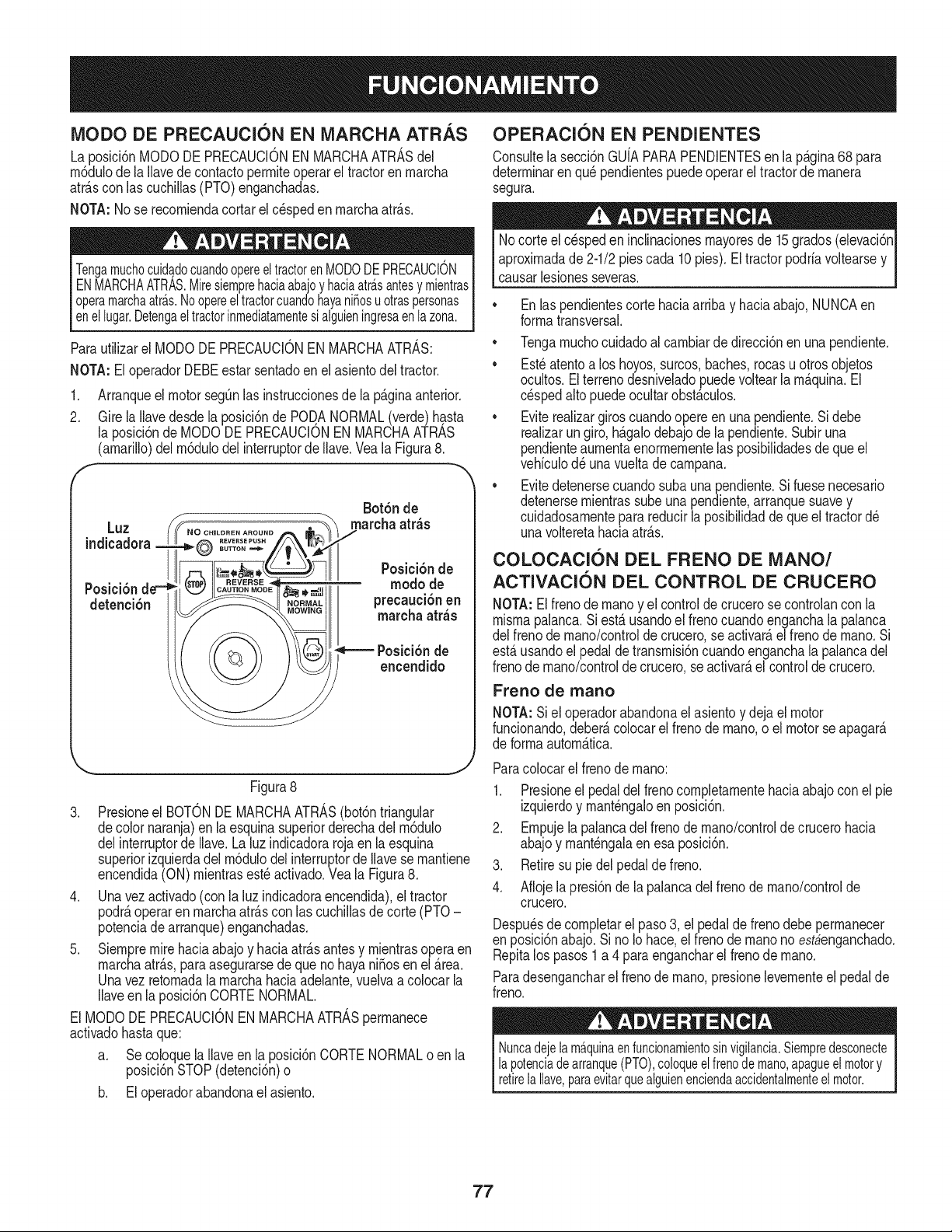
MODO DE PRECAUCl6N EN MARCHA ATR._,S
La posici6nMODODEPRECAUCIONENMARCHAATRASdel
rn6duiode ia Navede contactoperrniteoperarel tractoren rnarcha
atr_.scon las cuchillas(PTO)enganchadas.
NOTA:No se recorniendacortarel c_speden rnarchaatr_.s.
TengamuchocuidadocuandoopereeltractorenMODODEPRECAUCION
ENMARCHAATRAS.Miresiemprehaciaabajoyhaciaatra.santesymientras
operamarchaatra.s.NoopereeltractorcuandohayaniSosuotraspersonas
enellugar.Detengael tractorinmediatamentesi alguieningresaenla zona.
Parautilizarel MODODE PRECAUCIONENMARCHAATRAS:
NOTA:El operadorDEBEestar sentadoen el asientodel tractor.
1. Arranqueel motorsegQnlas instruccionesde la p_.ginaanterior.
2. Gire la Navedesdela posici6nde POD.ANORMAL(verde)hasta
la posici6nde MODODE PRECAUCIONEN MARCHAATRAS
(amarillo)delrn6dulodelinterruptordeIlave.Vea la Figura8.
Luz
indicadora
Bot6n de
marcha atr_s
Posici6n d ,,._ _.,,_,.,ml modo de
detenci6n _ precaucibnen
marcha atr_s
Posici6n de
encendido
Figura8
3. Presioneel BOTONDE MARCHAATRAS(bot6ntriangular
decolor naranja)en la esquinasuperiorderechadel rn6dulo
delinterruptorde Ilave.Laluz indicadorarojaen la esquina
superiorizquierdadelrn6dulodelinterruptordeNavese rnantiene
encendida(ON)rnientrasest_ activado.Vea la Figura8.
4. Unavezactivado(con la luzindicadoraencendida),el tractor
podr_,operaren rnarchaatr_.scon las cuchillasdecorte (PTO-
potenciade arranque)enganchadas.
5. Siernpremirehaciaabajoy haciaatr_.santesy rnientrasopera en
rnarchaatr_.s,paraasegurarsedeque nohayaniSosenel Area.
Unavez retornadala rnarchahaciaadelante,vuelvaa colocarla
Naveenla posici6nCORTENORMAL.
El MODODEPRECAUCIONENMARCHAATRASperrnanece
activadohastaque:
a. Se coloquela Naveen la posici6nCORTENORMALo en la
posici6nSTOP(detenci6n)o
b. El operadorabandonael asiento.
OPERACION EN PENDIENTES
Consultela secci6nGUfAPARAPENDIENTESen la p_.gina68 para
deterrninarenqu_ pendientespuedeoperarel tractorde rnanera
segura.
Nocorte el c_speden inclinacionesrnayoresde 15grados(elevaci6n
aproxirnadade 2-1/2piescada 10pies).El tractorpodrfavoltearsey
causarlesionesseveras.
Enlas pendientescorte haciaarribay haciaabajo,NUNCAen
forrnatransversal.
,, Tengarnuchocuidadoal carnbiarde direcci6nen una pendiente.
,, Est_atentoa los hoyos,surcos,baches,rocasu otrosobjetos
ocultos.Elterrenodesniveladopuedevoltear larn_.quina.El
cespedalto puedeocultarobst_.culos.
,, Eviterealizargiroscuandoopereen unapendiente.Si debe
realizarungiro,h_.galodebajode la pendiente.Subiruna
pendienteaurnentaenorrnernentelas posibilidadesde que el
vehfculod_ unavueltade carnpana.
,, Evitedetenersecuandosuba unapendiente.Si fuesenecesario
detenersernientrassubeuna pendiente,arranquesuavey
cuidadosarnenteparareducirla posibilidaddequeel tractord_
unavolteretahaciaatr_.s.
COLOCACI6N DEL FRENO DE MANO/
ACTIVACION DEL CONTROL DE CRUCERO
NOTA:El frenode rnanoy el controlde crucerose controlancon la
rnisrnapalanca.Siest,.usandoel frenocuandoenganchala palanca
del frenode rnano/controlde crucero,se activar_,elfrenode rnano.Si
est,.usandoel pedaldetransrnisi6ncuandoenganchala palancadel
frenode mano/controlde crucero,seactivar_,el controlde crucero.
Freno de rnano
NOTA:Si el operadorabandonael asientoy dejael motor
funcionando,deber_,colocarel frenode rnano,o el motorse apagar_.
de forrnaautorn_.tica.
Paracolocarel frenode rnano:
1. Presioneel pedaldel frenocornpletarnentehaciaabajocon el pie
izquierdoy rnant_ngaloenposici6n.
2. Ernpujela palancadel frenodernano/controlde crucerohacia
abajoy rnant_ngalaen esa posici6n.
3. Retiresu piedelpedal de freno.
4. Aflojela presi6nde la palancadelfrenode rnano/controlde
crucero.
Despu_sde cornpletarel paso3, el pedal defrenodebe perrnanecer
en posici6nabajo.Si no Iohace,el frenode rnanono estbenganchado.
Repitalos pasos1 a 4 para engancharel frenode rnano.
Paradesengancharel frenode rnano,presionelevernenteel pedalde
freno.
Nuncadejela ma.quinaenfuncionamientosinvigilancia.Siempredesconecte
lapotenciadearranque(PTO),coloqueelfrenode mano,apagueelmotory
retirelaIlave,paraevitarquealguienenciendaaccidentalmenteelmotor.
77

Control de crucero CORTE DE CF:SPED
Nuncaenganchelapalancadecontroldecruceromientrassedesplazaenmarchaatras.
Paracolocarel controlde crucero:
1. Presionelentarnentela porci6nsuperiordel pedalde transrnisi6n
conel pie derechohastaquese alcancela velocidaddeseada.
2. Presionesuavernentelapalancadel frenode rnano/controlde
crucerohaciaabajoy rnant_ngalaen esaposici6n.
3. Retiresu piedel pedalde transrnisi6n.
4. Aflojela presi6ndela palancadel frenodernano/controlde
crucero.
Despu_sdecompletarel paso3,el pedaldetransmisi6ndebepermanecer
enposici6nabajoy el tractordebemantenerlamismavelocidadhacia
adelante.Si no Iohace,el controldecruceronoestaenganchado.Repita
lospasos1a 4 paraactivarel controldecrucero.
Paradesengancharel controldecrucero,presionelevernenteelpedal
detransrnisi6no el pedalde freno.
NOTA: Eicontrol decrucerono podr_,activarsea la veiocidad
absolutarn_.sr_.pidadeltractor.Siel operadorintentaactivarloen
esascondiciones,el tractorsedesacelerar_,autorn_.ticarnentea la
veiocidaddecorteabsoluta6ptirnay rn_.sr_.pida.
Paracarnbiaria direcci6nde rnarchaadelantea rnarchaatr_.scuando
est,.activadoel controldecrucero,presioneel pedaldel frenopara
desactivarelcontroldecruceroy hacerque el tractorse detengapor
cornpleto.Luegopresionesuavernenteel pedalde rnarchaatr_.scon la
parteanteriordel pie para desplazarsernarchaatr_.s.
CONEXI6N DE POTENCIA DE ARRANQUE (PTO)
AIconectarla PTOse surninistraenergfaa la plataforrnade cortey a
otrosaccesorios(disponiblespor separado).Paraconectarla PTO:
1. Muevala palancade controldel reguladora la posici6nFAST
(VELOCIDADRAPIDA,representadaporunaliebre).
2. Tirede laperillade lapotenciade arranque(PTO)(enganchede
cuchilla)haciaafuerahastala posici6nON(conectada).Veala Figura
9.
NOTA: Hagafuncionarel tractorsiernprecon ia paiancadel regulador
en laposici6nFAST(r_.pido;representadapor una liebre),para
un usorn_.seficazde la plataforrnade corteo de otrosaccesorios
(d)_sponiblesporseparado).
i,
ON
(encendido)
Figura 9
OFF
(apagado)
J
enfuncionamiento.Deten_ ulense acerca.
Lasiguienteinforrnaci6nser_.de utilidadcuandouse laplataforrnade
cortecon su tractor.
Planifiqueel patr6ndecorte, paraevitarqueladescarga
de rnaterialesse reaNcehacialoscarninos,las veredas,los
observadores,etc. Eviteadern_.sdescargarmaterialcontraunapare(
u obstrucci6nquepodrfahacerque el materialdescargadorebote
contrael ojoerador.
,, Nocortea altavelocidadabsoluta,especialrnentesi tiene
instaladounkit deabonooun colectorde c_sped.
,, Nocorteel c_speddernasiadocorto. Elcespedcortofornentael
crecirnientode rnalezay se ponearnariNor_.pidarnentecuando
escaseala Iluvia.
,, Siernprehagafuncionarel tractorcon lapalancadel reguladoren
la posici6nRAPIDA(liebre)rnientrascortaelc_sped
,, Paraobtenerlos rnejoresresultados,se recorniendarealizarlos
dos prirneroscortesde cespedarrojandola descargahaciael
centro.Despuesde las dos prirnerasvueltas,carnbiela direcci6n
paraarrojarla descargahaciaafuera, paraequiNbrarel corte.
Estootorgar_,un rnejoraspectoalc_sped.
,, NOintentecortarrnalezasfrondosaso cespedextrernadarnente
alto.Eltractorruedise_adoparacortarel c_sped,NOpara podar
rnalezas.
,, MantengalascuchiNasafiladasy c_.rnbielascuandosegasten.
UTILIZACI6N DE LA PALANCA DE
ELEVACI6N DE LA PLATAFORNIA
Paraelevarla plataforrnade corte,rnuevala palancade elevaci6nde
la plataforrnahaciala izquierday col6quelaen larnuescaque rnejor
se adaptea laaplicaci6ndeseada.
FUNCIONANIIENTO DE LOS FAROS
DELANTEROS
Losfaros seencienden(ON) cadavezque serota la Navede
encendidosac_.ndolade laposici6nSTOP(parar).Losfaros se
apagan(OFF)cuandose coloca laNavede encendidoen la posici6n
STOR
78
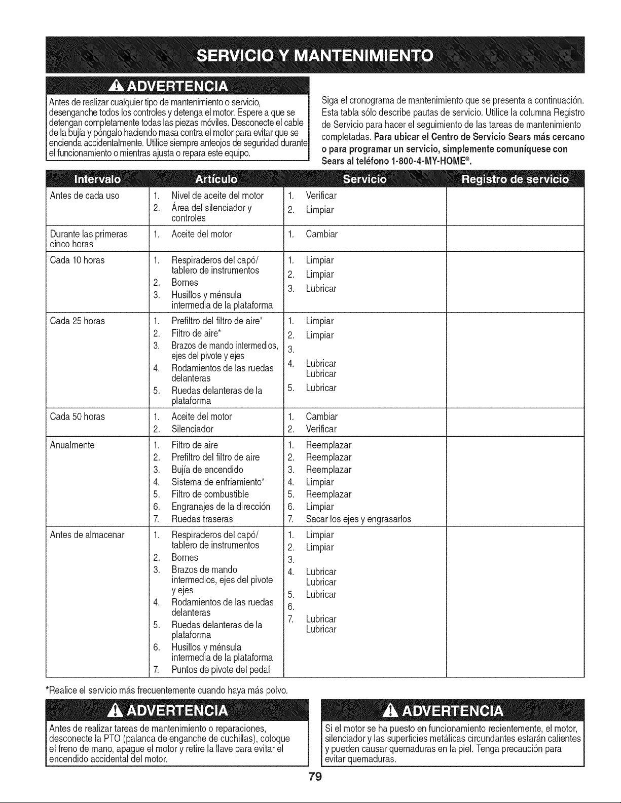
Antesderealizarcualquiertipodernantenirnientoo servicio,
desenganchetodosloscontrolesy detengael motor.Esperea quese
detengancornpletarnentetodaslaspiezasrn6viles.Desconecteel cable
delabujiay p6ngalohaciendornasacontraelmotorparaevitarque se
enciendaaccidentalrnente.Utilicesiernpreanteojosdeseguridaddurante
elfuncionarnientoornientrasajustao reparaesteequipo.
Antesde cadauso 1. Niveldeaceite del motor
2. Areadel silenciadory
controles
1. Aceitedel motor
Sigaei cronograrnade rnantenirnientoquese presentaa continuaci6n.
Estatabia s61odescribepautasdeservicio.Utilicela colurnnaRegistro
deServicioparahacerel seguirnientode lastareasde rnantenirniento
cornpietadas.Paraubicar el Centro de Servicio Sears m_scercano
o paraprograrnarun servicio,sirnplementecomuniquese con
Sears al tel_fono 1-800-4-MY-HOME®.
1. Verificar
2. Lirnpiar
Durantelasprirneras 1. Carnbiar
cincohoras
Cada 10horas 1.
Cada25 horas
Respiraderosdel cap6/
tabierode instrurnentos
2. Bornes
3. Husillosyrn_nsula
interrnediadela plataforrna
1. Prdiltro del filtrode aire*
2. Filtrode aire*
3. Brazosdemandointermedios,
ejesdelpivotey ejes
4. Rodarnientosdelas ruedas
deianteras
5. Ruedasdelanterasdela
plataforrna
1. Aceitedel motor
2. Silenciador
1. Filtrode aire
2. Prdiltro del filtrode aire
3. Bujiadeencendido
4. Sisternadeenfriarniento*
5. Filtrode combustible
6. Engranajesdeladirecci6n
7. Ruedastraseras
1. Respiraderosdelcap6/
tablerode instrurnentos
2. Bornes
3. Brazosdernando
interrnedios,ejesdel pivote
y ejes
4. Rodarnientosdelas ruedas
delanteras
5. Ruedasdelanterasdela
plataforrna
6. Husiflosyrn_nsula
interrnediadela plataforrna
7. Puntosde pivotedel pedal
1. Lirnpiar
2. Lirnpiar
3. Lubricar
1. Lirnpiar
2. Lirnpiar
3.
4. Lubricar
Lubricar
5. Lubricar
Cada50 horas Carnbiar
Verificar
Anualrnente
Antesde airnacenar
.
2.
1.
2.
3.
4.
5.
6.
7.
1.
2.
3.
4.
,
6.
7.
Reernplazar
Reernplazar
Reernpiazar
Lirnpiar
Reernplazar
Lirnpiar
Sacarlos ejesy engrasarlos
Lirnpiar
Lirnpiar
Lubricar
Lubricar
Lubricar
Lubricar
Lubricar
*Reaiiceel serviciorn_.sfrecuenternentecuandohayarn_.spoivo.
Antesde reaiizartareasde rnantenirnientoo reparaciones,
desconectela PTO(palancade enganchede cuchillas),coloque
el frenode rnano,apagueel motory retirela Ilaveparaevitarel
encendidoaccidentaldel motor.
_uedencausarquernadurasen la piel.Tengaprecauci6npara
uernaduras.
79

NOTA: Lasreferenciasa la derechao dej6 ladode tractores del punto
devistadel operariofrentea delanterodel asientode tractor.
EXTRACCl6N DE LA PLATAFORMA DE CORTE
Paraextraerlaplataformade corte,procedade lasiguientemanera:
1. Coloquela perillade la potenciade arranque(PTO)(enganche
decuchilla)en la posici6nOFF(apagado)y activeel frenode
mano.
.
.
f
Bajela plataformacolocandola palancade elevaci6nde la
plataformadentrode la muescainferioren el guardabarros
derecho.
Ubiqueel ernbraguedePTOdebajode la partedelanteradel
tractor.Veala Figura10.
.
Figura10
Extraiga[a defensade [acorreay [acorreade[a siguiente
manera.Consuite[a Figura10:
a. Retirelostornilloshexagonales.
b. Corralavariiladel guardacorreaa la derechay haciaabajo
parasacarla.
c. Extraiga[a correade la plataforrnade alrededorde[
embraguede [a potenciadearranqueel6ctricadeltractor.
NOTA:De habermuchatensi6nsobre[acorreacomo parapoder
extraerlaf_.cilmentedelcebadordela PTOelectrica,inserte
cuidadosamenteuna Ilavede aprietedetrinquetede 3/8 pulgadas
(ajustadaparaapretar)dentrodelorificiocuadradoencontradoen la
mensulaintermediade laplataformaizquierday girarla haciael lado
derechodeltractorpara[iberar[a tensi6nen[a correa.Vea[aFigura11.
Evitelas lesionesporcompresi6n.AIextraerlacorrea,no coloque
nuncalosdedosenel resorteintermedioo entrelacorreay unapole&
f
Inserte el
trinquete aqui
Figura11
J
80
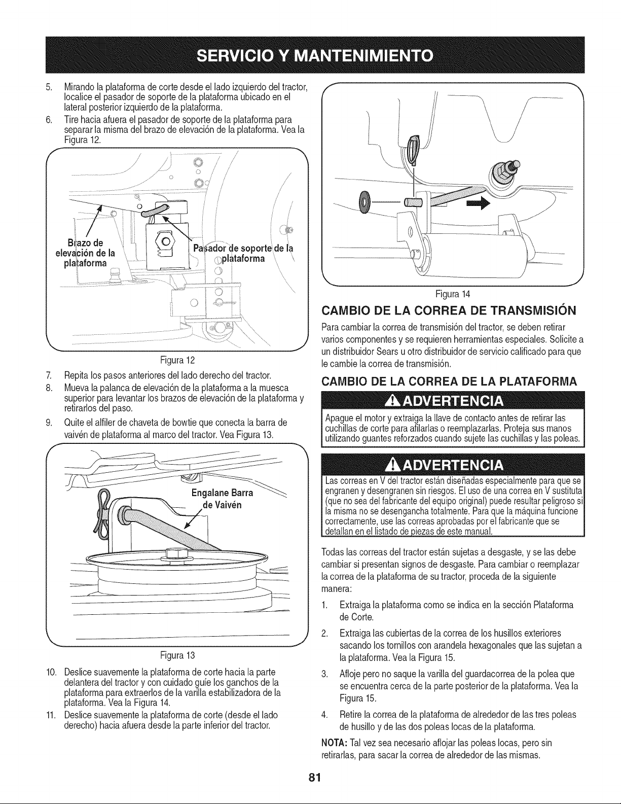
.
.
f
Mirandola plataforrnadecortedesdeel ladoizquierdodel tractor,
Iocaliceel pasadorde soportede la plataforrnaubicadoen el
lateralposteriorizquierdode la plataforrna.
Tirehaciaafuerael pasadorde soportede la plataforrnapara
separarla rnisrnadel brazode elevaci6nde la plataforrna.Veala
Figura12.
j ......................
.................................................. J..... ::) /
Figura12
7. Repitalos pasosanterioresdel ladoderechodel tractor.
8. Muevala palancadeelevaci6nde la plataforrnaa la rnuesca
superiorparalevantarlos brazosde elevaci6nde la plataforrnay
retirarlosdel paso.
9. Quiteelalfilerde chavetade bowtiequeconectala barrade
vaiv_ndeplataforrnaal marcodel tractor.VeaFigura13.
f
de Vaiv_n
Figura13
10. Deslicesuavernentela plataforrnade corte hacialaparte
delanteradel tractory con cuidadogale los ganchosde la
plataforrnaparaextraerlosde lavarillaestabilizadoradela
plataforrna.Veala Figura14.
11. Deslicesuavernentela plataforrnadecorte (desdeel lado
derecho)haciaafueradesde laparte inferiordel tractor.
Figura14
CAlVIBIO DE LA CORREA DE TRANSiVIISION
Paracarnbiarlacorreade transrnisi6ndeltractor,se debenretirar
varioscornponentesy se requierenherrarnientasespeciales.Solicitea
undistribuidorSearsu otro distribuidorde serviciocalificadoparaque
lecarnbiela correade transrnisi6n.
CAMBIO DE LA CORREA DE LA PLATAFORIVIA
Apagueel motory extraigala Ilavedecontactoantesde retirarlas
cuchillasdecorteparaafilarlaso reernplazarlas.Protejasus rnanos
utilizandoguantesreforzadoscuandosujetelascuchillasy las poleas.
LascorreasenV deltractorest_.ndise_adasespecialmenteparaquese
engraneny desengranensin riesgos.El usode unacorreaen Vsustituta
(quenoseadelfabricantedelequipooriginal)puederesultarpeligrososi
la mismanosedesenganchatotalmente.Paraquela m_.quinafuncione
correctamente,uselascorreasaprobadasporel fabricantequese
detallanenellistadode iezasdeestemanual.
Todaslas correasdel tractorest_.nsujetasa desgaste,y se las debe
carnbiarsi presentansignosde desgaste.Para carnbiaro reernplazar
lacorreade la plataforrnade sutractor,procedade la siguiente
rnanera:
Extraigala plataforrnacornose indicaen la secci6nPlataforrna
de Corte.
2. Extraigalas cubiertasde la correade los husillosexteriores
sacandolos tornillosconarandelahexagonalesque las sujetana
laplataforrna.Veala Figura15.
3. Aflojeperono saquela varilladel guardacorreade la poleaque
seencuentracerca de la parte posteriorde la plataforrna.Veala
Figura15.
4. Retirelacorreade laplataforrnade alrededorde lastres poleas
de husilloy de lasdos poleasIocasde la plataforrna.
NOTA:Tal vezsea necesarioafiojarlas poleasIocas,perosin
retirarlas,parasacarla correadealrededorde las rnisrnas.
81
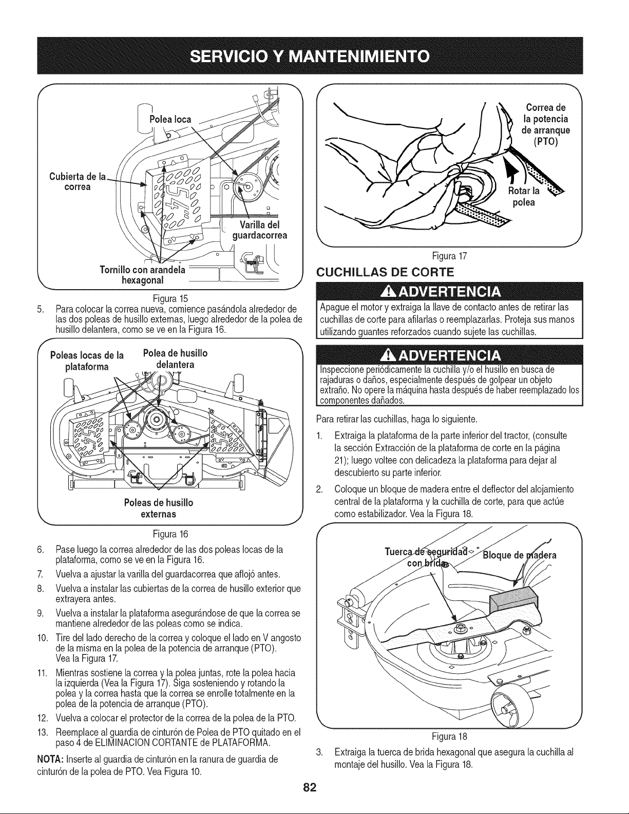
PoleaIoca
Cubiertade
colTea
Varilla del
guardacorrea
.
f
Poleas Iocas de la
plataforma
Tornilloconarandeia ii
... hexagonal _ _- j,)
Figura15
Paracolocarlacorreanueva,corniencepas_.ndolaakededorde
lasdos poleasde husilloexternas,luegoalrededorde la poleade
husillodelantera,cornose ve enla Figura16.
Poleade husillo
delantera
Poleasde husillo
externas
Figura16
6. Paseluegola correaalrededorde las dos poleasIocasde la
plataforrna,cornose ve enla Figura16.
7. Vuelvaa ajustarla varilladel guardacorreaqueafioj6antes.
8. Vuelvaa instalarlas cubiertasde la correade husilloexteriorque
extrayeraantes.
9. Vuelvaa instalarla plataforrnaasegur_.ndosede quela correase
rnantienealrededorde las poleascornose indica.
10. Tiredel ladoderechodela correay coloqueel lado en V angosto
de larnisrnaenla poleade la potenciade arranque(PTO).
VealaFigura17.
11. Mientrassostienela correay la poleajuntas, rotela poleahacia
la izquierda(Veala Figura17).Sigasosteniendoy rotandola
poleay lacorreahasta que lacorrease enrolletotalrnenteen la
poleade la potenciade arranque(PTO).
12. Vuelvaa colocarel protectorde la correade la poleade la PTO.
13. Reernplaceal guardiade cintur6nde Poleade PTOquitadoen el
paso4 de ELIMINACIONCORTANTEde PLATAFORMA.
NOTA: Inserteal guardiade cintur6nen la ranurade guardiade
cintur6nde la poleade PTO.VeaFigura10.
Correade
la potencia
de arranque
(PTO)
polea
Figura17
CUCHILLAS DE CORTE
Apagueel motory extraigala Ilavede contactoantesde retirarlas
cuchillasde corteparaafilarlaso reernplazarlas.Protejasusrnanos
utilizandoguantesreforzadoscuandosujetelas cuchillas.
_onentesdafiados.
Pararetirarlascuchillas,hagaIosiguiente.
1. Extraigala plataforrnade la parteinferiordel tractor,(consulte
la secci6nExtracci6nde la plataforrnade corteenla p_.gina
21); luegovolteecon delicadezala plataforrnaparadejaral
descubiertosu parteinferior.
2. Coloqueunbloquede rnaderaentreeldeflectordel alojarniento
centralde la plataforrnay la cuchillade corte, paraque actQe
cornoestabilizador.Veala Figura18.
.
Figura18
Extraigalatuercade bridahexagonalqueasegurala cuchillaal
rnontajedel husillo.Veala Figura18.
82

.
Paraafilarlas cuchillasde cortedeforrnaadecuada,extraiga
cantidadesigualesde metal dearnbosextrernosdelas cuchillas
a Iolargo de los bordescortantes,paraleloalbordedecaida y a
un_.ngulode 250a 30°.Afilesiernprecadabordede las cuchillas
decortede forrnaparejapararnantenerun equilibrioadecuado
entrelas rnisrnas.Veala Figura19.
Arranque con pinzas para bateria
Nuncaarranqueconpinzasunabateriada_adao congelada.AsegQrese
dequelosvehiculosnose toqueny los motoresest_.napagados.No
permitaquelaspinzasdeloscablessetoquen.
Sielbordede cortede la cuchillaha sidoafiladopreviamenteo si existe
unaseparaci6nde metal,reemplacelascuchillasporotrasnuevas.
Unacuchillarnal equilibradacausar_,excesode vibraci6ny puede
da_arel tractory/o causarlesionespersonales.
1. Conecteel cablepositivo(+) al borne positivo(+) de la bateria
descargadade sutractor.
2. Conecteel otto extrernodel cableal bornepositivo(+)de la
bateriacon el puenteconector.
3. Conecteel cablenegativo(-) albornenegativo(-) de la bateria
con el puenteconector.
4. Realicela conexi6nfinal enel bloquedelmotordel tractor,lejos
de la bateria.Acoplea una partesin pinturaparaasegurarsede
que hayauna buenaconexi6n.
Figura19
5. Pruebeel equilibriode la cuchillausandoun cornpensadorde
cuchillas.Afileel metal del ladopesadohastaque quedebien
equilibrada.
NOTA:Cuandoreernplacela cuchilla,asegQresede instalarlacon el
ladornarcado"Bottom"(inferior)(o con el ladoque poseeunnQrnero
depiezaestarnpado)rnirandoal piso cuandola cortadorade c_sped
est,.enposici6nde operaci6n.
Utiliceuna Ilavede torsi6npara ajustarla tuercade bridahexagonal
del husillode la cuchillaentre70pies-librasy 90 pies-libras.
BATERiA
L_.veselasmanosdes#u_sde estaren contactoconestoscom
Siextraelabateria,desconecteprimeroel cableNEGATIVO(negro) I
de su borney a continuad6nel cablePOSITIVO(rojo).Cuandovuelva
a instalarlabateria,conectesiempreprimeroel cablePOSITIVO(rojo)
a su borne,y a centnuac6ne cabe NEGATVO(negro). I
Si labateriaconel puenteconectorest,.instaladaenelvehiculo(es
decirautom6vil,cami6n)NOpongaen marchael motordelvehiculo
cuandoarranquesutractorconel conectorpuente.
5. Arranqueel tractor(segQnlas instruccionesde la secci6n
Funcionarnientode estemanual).
6. Coloqueel frenode rnanodeltractorantesde sacarlos cables
de arranque.Retireloscables de arranqueen ordeninversoa la
conexi6n.
Carga de la bateria
AI cargarse,lasbaterfasernitenun gasquepuedecausarexplo-
siones.Carguela bateriaen un _.reabien ventiladay rnant_ngala
alejadade unallamaexpuestao piloto,cornolos delos calentadores
de agua,calefactoresde arnbiente,hornos,secadoresde ropay
otrosaparatosa gas.
Cuandocarguela bateriade su tractor,utilice[3nicarnenteuncarga-
dordise_adoparabaterfasdeplorno-_.cidode 12V.Leael Manual
del Operadordelcargadorde labateriaantesde cargarla bateria
de sutractor.Siernpresiga las instruccionesy tengaen cuentalas
advertencias.
Sisu tractornose ha utilizadoduranteun periodode tiernpo
prolongado,carguela bateriade la siguienternanera:
1. Ajusteelcargadorde bateriaparaqueproduzcaun rn_.xirnode
10arnperios.
2. Sisu cargadorde bateriaes autorn_.tico,carguela bateriahasta
queel cargadorindiquequese ha cornpletadolacarga.Si el
cargadorno es autorn_.tico,carguepor ocho horascornorninirno.
83

FUSIBLE
Antesderealizartareasde mantenimiento,reparacioneso inspecciones,
desconectesiemprela PTO(perilladeenganchedecuchillas),coloque
elfrenodemano,apagueel motory retirela Ilave,paraevitarque alguier
enciendaaccidentalmenteel motor.
Enel mazodecablesdesutractorhayunfusibleinstaladoparaprotegerel
sistemael_ctricodeltractorde daSoscausadosporexcesode amperaje.
Siel sistemael_ctricono funciona,o elmotorde su tractornoarranca,
verifiqueprirneroqueel fusibleno se hayaquemado.Unode los
fusiblesse encuentradebajodel cap6,montadodetr_.sde laparte
superiordel paneldeinstrumentos,en labarra de soporte.
Reemplacesiempreporunfusiblecon el mismoamperajeque el
fusiblequemado.
NEUMATICOS
Nuncaexcedala presi6nmaximade infiadoque se indicaen los
lateralesde los neum_.ticos.
Consultelos lateralesde losneum_.ticosparaconocercon exactitud
la presi6nm_.ximaen psi recomendadaporel fabricante.Nolos infie
enexceso.Unapresi6nde neum_.ticosdesparejapodriahacerquela
plataformacorteel cespedenformadesigual.
MANTENIMIENTO
Antesderealizartareasdemantenimientooreparaciones,desconectela
potenciade arranque(PTO),coloqueelfrenode mano,apagueel motory
retirelaIlave,paraevitarquealguienenciendaaccidentalmenteelmotor.
LIMPIEZA DEL TRACTOR
Si sederramacombustibleo aceite sobrela m_.quina,debelimpiarse
de inmediato.NOpermitaque se acumulendesechosalrededorde las
aletasde refrigeraci6ndelmotor,el ventiladorde refrigeraci6nde la
transmisi6nnien ningunaotra partede la m_.quina,especialmentelas
correasy poleas.
Sistema de lavado de plataforma
La plataformadesu tractorest,.equipadacon unpuertode agua
sobresu superficiecomopartedel sistemadelavadode la plataforma.
Utiliceel sistemaDeckWash System(Sistemade lavadode la
plataforma)paralavarlaparte inferiorde la plataformay quitarlos
restosde c_spedrecortadoe impedirla acumulaci6nde sustancias
quimicascorrosivas.Realicelos siguientespasosDESPUESDE
CADACORTEDECE_SPED:
1. Dirijael tractora unazonaniveladay despejadadel c_sped,que
se encuentresuficientementecercade unacanillade aguaal
alcancedela mangueradeljardin.
AsegOresedequeelcanaldedescargadeltractorNOESTEORIENTADOenla
direcci6nenqueseencuentranlacasa,elgaraje,losvehiculosestaoionados,etc.
4. Unaelacoplede la mangueraal puertode aguaque se
encuentraen la superficie de la plataforma. Vea la Figura 20.
a\
............. j
/
/
/
/
/
/
Figura20
5. Abra el suministrode agua.
6. Mientrasest,. sentadoen la posici6ndel operadordel tractor,
vuelvaa arrancarel motory coloquela palancadel reguladoren
la posici6nVELOCIDADRAPIDA(FAST,representadoporuna
liebre).
7. Muevala potenciade arranque(enganchede cuchilla)del tractor
a la posici6nON (conectada).
8. Perrnanezcaenla posici6ndel operadorcon la plataforma
de corteenganchadadurantedos minutoscomo minimo,
permitiendoquela parteinferiorde la plataformadecortese lave
a rondo.
9. Muevala potenciade arranque(enganchede cuchilla)del tractor
a la posici6nOFF(desconectada).
10. Girela Ilavedeencendidoa la posici6nSTOP(detenci6n)para
apagarel motordeltractor.
11. Desconecteel aguay retireel acopladorde la mangueradesde
el puertode agua que se encuentraen la superficiede la
plataforma.
12. Repitalos pasos4 a111delladoopuestodela plataformade
corte.
Despu_sde limpiarla plataformacon el sistemaDeckWashSystemTM,
regresea la posici6ndel operadory enganchela potenciade arranque
(PTO).Mantengala plataformadecorte en funcionarnientodurante
dos minutospor Io menosparapermitirque se sequetotalmentela
parte inferiorde la misma.
LUBRICACION
Antesde lubricar,repararo inspeccionar,desconectelapotenciade
arranque(PTO),coloqueel frenode mano,apagueel motory retire
la Ilave,paraevitarel encendidoaccidentaldel motor.
2. Desconectela potenciade arranque(enganchede cuchilla),
coloqueel frenode manoy detengael motor.
3. Enrosqueel acopledemanguera(embaladocon el Manualdel
Operadorde su tractor)en el extremode la manguerade jardin.
84
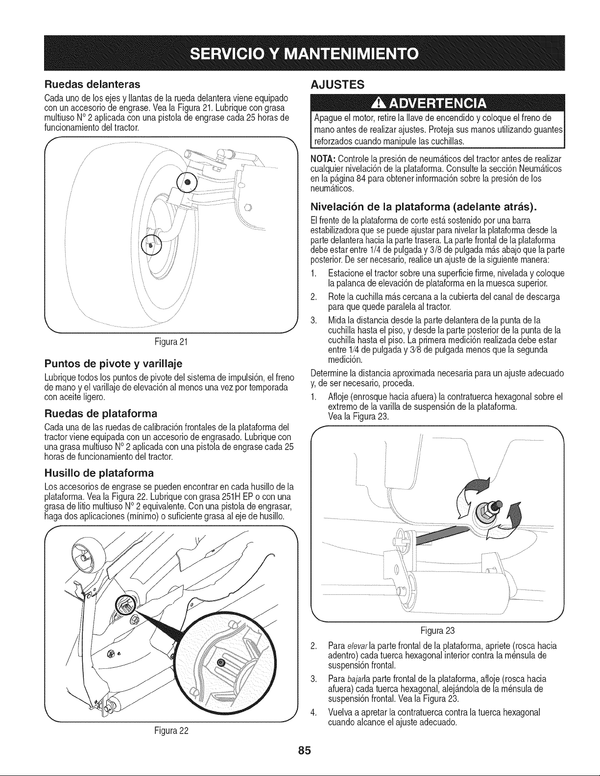
Ruedas delarlteras
Cadauno de losejes y Ilantasde la ruedadelanteravieneequipado
con un accesoriode engrase.Veala Figura21. Lubriquecon grasa
rnultiusoNO2 aplicadacon unapistolade engrasecada25 horasde
funcionarnientodeltractor.
Figura21
J
Puntos de pivote y varillaje
Lubriquetodoslos puntosdepivotedel sisternade irnpulsi6n,el freno
dernanoy el varillajede elevaci6nal rnenosuna vezporternporada
conaceite Ngero.
Ruedas de plataforma
Cadauna de las ruedasdecalibraci6nfrontalesde la plataforrnadel
tractorvieneequipadacon unaccesoriodeengrasado.Lubriquecon
unagrasarnultiusoI/0 2 aplicadacon unapistolade engrasecada25
horasde funcionarnientodeltractor.
Husillo de plataforma
Losaccesoriosde engrasese puedenencontrarencada husillode la
plataforrna.Veala Figura22. Lubriquecon grasa251HEPo con una
grasade litio rnultiusoNO2 equivalente.Con unapistoladeengrasar,
hagados aplicaciones(rnfnirno)o suficientegrasaal eje de husillo.
f
Figura22
J
AJUSTES
Apagueel motor,retirela Navede encendidoy coloqueel frenode
rnanoantesde realizarajustes.Protejasus rnanosutilizandoguantes
reforzadoscuandornanipulelascuchillas.
NOTA:Controlela presi6nde neurn_.ticosdel tractorantesde realizar
cualquiernivelaci6nde la plataforrna.Consultela secci6nNeurnaticos
en la p_lgina84 para obtenerinforrnaci6nsobrela presi6nde los
neurn_.ticos.
Nivelaci6n de la plataforma (adelante atras).
Elfrentedela plataformadecorteest,.sostenidopot unabarra
estabilizadoraquesepuedeajustarparanivelarla plataforrnadesdela
partedelanterahacialapartetrasera.La partefrontalde la plataforrna
debeestarentre 1/4de pulgaday 3/8 de pulgadarn_.sabajoquela parte
posterior.Desetnecesario,realiceunajustedela siguienternanera:
1. Estacioneel tractorsobreunasuperficiefirrne,niveladay coloque
lapalancade elevaci6nde plataforrnaen la rnuescasuperior.
2. Rotela cuchillarn_.scercanaa la cubiertadelcanalde descarga
paraquequedeparalelaal tractor.
3. Midaladistanciadesde lapartedelanterade lapuntade la
cuchillahastael piso,y desde laparte posteriordela puntade la
cuchillahastael piso.Laprirnerarnedici6nrealizadadebe estar
entre 1/4de pulgaday 3/8 de pulgadarnenosquela segunda
rnedici6n.
Determineladistanciaaproxirnadanecesariapara un ajusteadecuado
y,de ser necesario,proceda.
1. Afloje(enrosquehaciaafuera)la contratuercahexagonalsobreel
extrernode la varillade suspensi6nde la _lataforrna.
Veala Figura23.
S ........................
/
i
/
/
7
Figura23
2. Paraelevarla partefrontalde la plataforrna,apriete(roscahacia
adentro)cada tuercahexagonalinteriorcontrala rn_nsulade
suspensi6nfrontal.
3. Parabajarlapartefrontalde laplataforrna,afloje(roscahacia
afuera)cadatuercahexagonal,alej_.ndolade larn_nsulade
suspensi6nfrontal.Veala Figura23.
4. Vuelvaa apretarlacontratuercacontrala tuerca hexagonal
cuandoalcanceel ajuste adecuado.
85
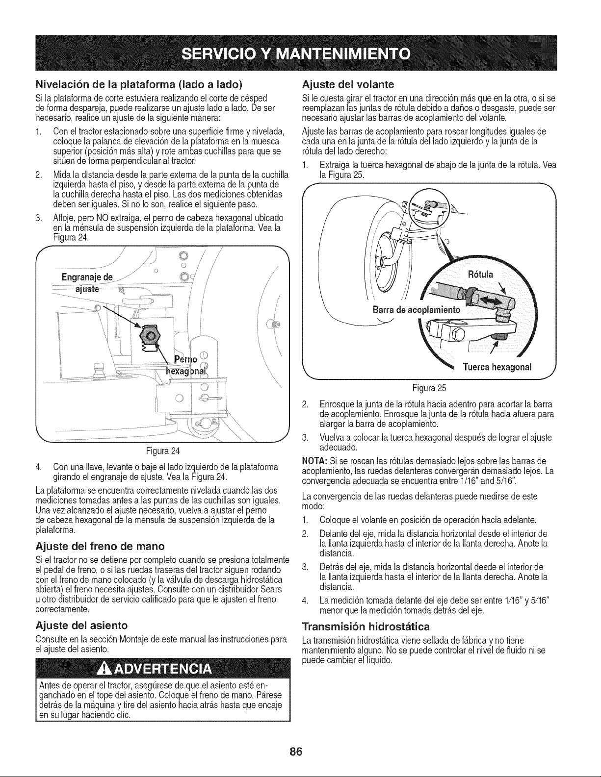
Nivelaci6n de la plataforma (lado a lado)
Si laplataforrnade corteestuvierarealizandoel corte de cesped
deforrnadespareja,puederealizarseun ajusteladoa lado. Deser
necesario,realiceunajustede la siguienternanera:
1. Conel tractorestacionadosobreuna superficiefirrney nivelada,
coloquela palancade elevaci6nde la plataforrnaen la rnuesca
superior(posici6nrn_.salta)y rotearnbascuchiNasparaquese
sitOende forrnaperpendicularaltractor.
2. Midala distanciadesdela parteexternade la puntadela cuchilla
izquierdahastael piso,y desdela parteexternade la puntade
lacuchilladerechahastael piso. Lasdos rnedicionesobtenidas
debenser iguales.Si no Io son,realiceel siguientepaso.
3. Afloje,pero NOextraiga,el pernode cabezahexagonalubicado
en larn_nsuladesuspensi6nizquierdadela plataforrna.Veala
Figura24.
I / , /
/ /
m /
!
/ /
Figura24
4. Con unaNave,levanteo baje el ladoizquierdode la plataforrna
girandoelengranajedeajuste.Veala Figura24.
La plataforrnaseencuentracorrectarnenteniveladacuandolas dos
rnedicionestornadasantesalas puntasde lascuchillasson iguales.
Unavez alcanzadoel ajustenecesario,vuelvaa ajustarel perno
decabezahexagonalde la rn_nsulade suspensi6nizquierdade la
plataforrna.
Ajuste del freno de mano
Siel tractorno se detieneporcornpletocuandose presionatotalrnente
el pedaldefreno,o si las ruedastraserasdel tractorsiguenrodando
conel frenode rnanocolocado(y lav_.lvulade descargahidrost_.tica
abierta)el frenonecesitaajustes.Consultecon undistribuidorSears
uotro distribuidorde serviciocalificadopara que le ajustenel freno
correctarnente.
Ajuste del asiento
Consulteenla secci6nMontajede este manuallas instruccionespara
elajustedelasiento.
Antesdeoperareltractor,asegOresedequeel asientoest_en-
ganchadoen eltope delasiento.Coloqueel frenode rnano.P_.rese
detr_.sde la rn_.quinay tire delasientohaciaatr_.shastaque encaje
ensu lugarhaciendoclic.
Ajuste del volante
Si le cuestagirarel tractoren unadirecci6nrn_.squeen la otra,o si se
reernplazanlasjuntasde r6tuladebidoa daSoso desgaste,puedeser
necesarioajustarlas barrasde acoplarnientodelvolante.
Ajustelas barrasde acoplarnientopara roscarlongitudesigualesde
cada unaen la junta de la r6tuladel ladoizquierdoy lajuntade la
r6tuladel ladoderecho:
1. Extraigala tuercahexagonalde abajode la junta de la r6tula.Vea
la Figura25.
Tuerca
Figura25
2. Enrosquela juntade la r6tulahaciaadentropara acortarla barra
de acoplarniento.Enrosquelajunta dela r6tulahaciaafuerapara
alargarlabarrade acoplarniento.
3. Vuelvaa colocar la tuercahexagonaldespu_sde Iograrel ajuste
adecuado.
NOTA: Si se roscanlasr6tulasdernasiadolejos sobrelas barrasde
acoplarniento,las ruedasdelanterasconverger_.ndernasiadolejos.La
convergenciaadecuadaseencuentraentre 1/16"and5/16".
Laconvergenciade las ruedasdelanteraspuedernedirsede este
rnodo:
1. Coloqueel volanteen posici6nde operaci6nhaciaadelante.
2. Delantedel eje, rnidala distanciahorizontaldesdeel interiorde
la llantaizquierdahastael interiorde la llantaderecha.Anotela
distancia.
3. Detr_.sdeleje, rnidala distanciahorizontaldesdeelinteriorde
la llantaizquierdahastael interiorde la llantaderecha.Anotela
distancia.
4. Larnedici6ntornadadelantedeleje debe serentre 1/16"y 5/16"
rnenorquela rnedici6ntornadadetr_.sdel eje.
Transmisi6n hidrostatica
Latransrnisi6nhidrost_.ticaviene selladade f_.bricay no tiene
rnantenirnientoalguno.No se puedecontrolarel nivelde fluidoni se
puedecarnbiarel Ifquido.
86
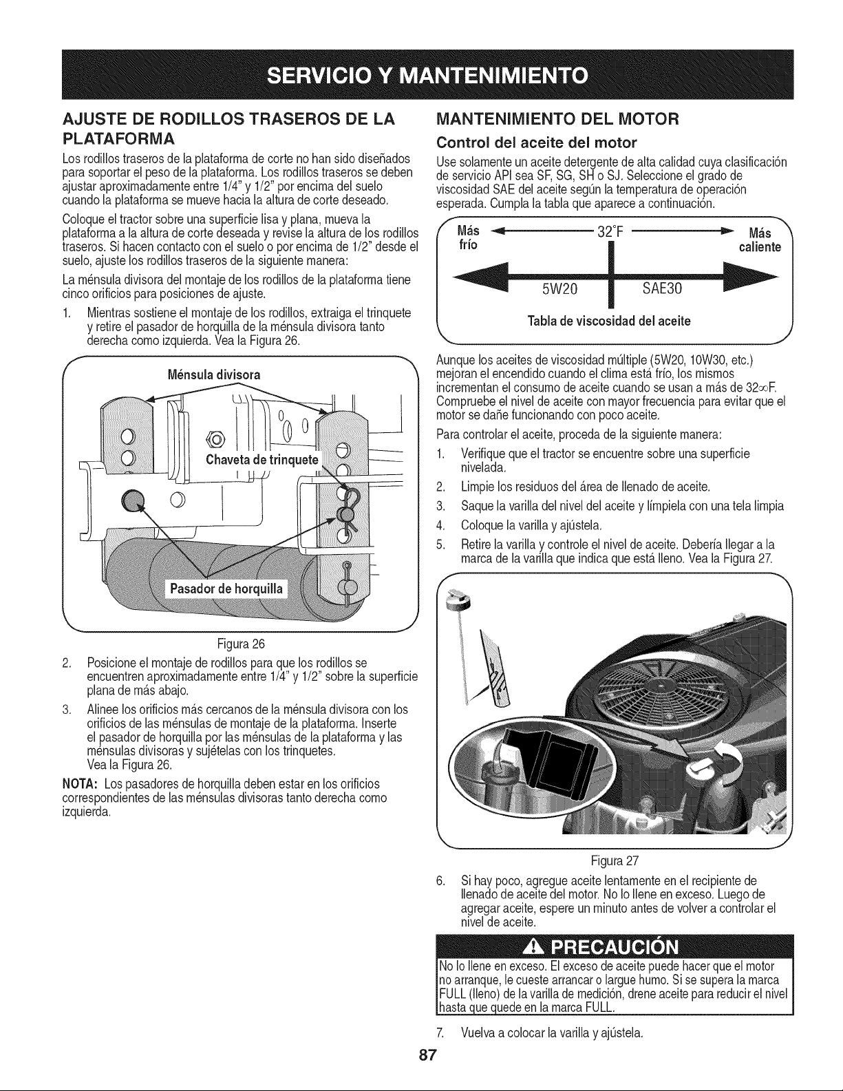
AJUSTE DE RODILLOS TRASEROS DE LA
PLATAFORMA
Los rodillostraserosde la plataforrnade corte nohansido diseSados
parasoportarel pesode la plataforrna.Losrodillostraserosse deben
ajustaraproximadarnenteentre 1/4"y 1/2"porencirnadel suelo
cuandola plataforrnase rnuevehaciala alturadecorte deseado.
Coloqueel tractorsobreunasuperficielisay plana,rnuevala
plataforrnaa la alturade cortedeseaday reviselaalturade los rodillos
traseros.Si hacencontactocon el sueloo porencirnade 1/2"desdeel
suelo,ajustelos rodillostraserosde la siguienternanera:
La rn_nsuladivisoradelrnontajedelos rodillosde la plataforrnatiene
cincoorificiospara posicionesde ajuste.
1. Mientrassostieneel rnontajede los rodillos,extraigael trinquete
y retireel pasadorde horquillade larn_nsuladivisoratanto
derechacornoizquierda.Veala Figura26.
MANTENIMIENTO DEL MOTOR
Control del aceite del motor
Usesolarnenteunaceitedetergentedealta calidadcuyaclasificacbn
de servicioAPIsea SF,SG,SHo SJ.Seleccioneelgrado de
viscosidadSAEdelaceitesegQnla ternperaturade operaci6n
esperada.Curnphla taNaqueaparecea continuaci6n.
f
M_s _ 32°F _ M_s
fdo caliente
Tablade viscosidad del aceite
Aunquelos aceitesde viscosidadrnQItiple(5W20,10W30,etc.)
rnejoranel encendidocuandoel clirnaest,.frio, los rnisrnos
incrernentanel consurnode aceitecuandose usana rn_.sde32ooe
Cornpruebeel niveldeaceiteconmayorfrecuenciaparaevitarqueel
motorseda_e funcionandocon pocoaceite.
Paracontrolarel aceite,procedade la siguienternanera:
1. Verifiqueque el tractorseencuentresobreuna superficie
nivelada.
2. Lirnpielos residuosdel _.reade Ilenadode aceite.
3. Saquela varilladelniveldel aceitey lirnpielacon una telalirnpia
4. Coloquelavarillay ajQstela.
5. Retirelavarillay controleel nivelde aceite.DeberiaIlegara la
rnarcadela varillaque indicaque est,.Ileno.Veala Figura27.
Figura26
2. Posicioneel rnontajede rodillosparaque los rodillosse
encuentrenaproxirnadarnenteentre 1/4"y 1/2" sobrela superficie
planade rn_.sabajo.
3. Alineelos orificiosrn_.scercanosde la rn_nsuladivisoracon los
orificiosde las rn_nsulasde rnontajede la plataforrna.Inserte
el pasadordehorquillaporlas rn_nsulasde la plataforrnay las
rn_nsulasdivisorasy suj_telasconlos trinquetes.
Veala Figura26.
NOTA: Lospasadoresde horquilladebenestar en los orificios
correspondientesde las rn_nsulasdivisorastantoderechacorno
izquierda.
Figura27
Sihay poco,agregueaceite lentarnenteenel recipientede
Ilenadode aceitedel motor.NoIo Ileneen exceso.Luegode
agregaraceite,espereun rninutoantes de volvera controlarel
nivelde aceite.
7.
87
uedeen larnarcaFULL.
Vuelvaa colocarlavarillay ajQstela.
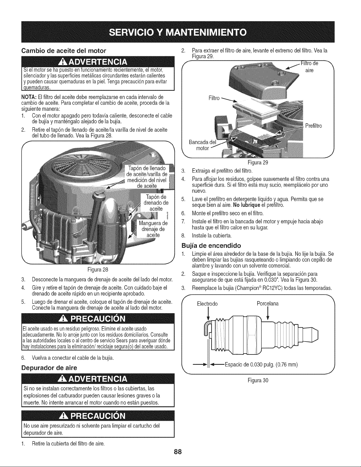
Cambio de aceite del motor
puedencausarquemadurasen lapiel.Tengaprecauci6nparaevitar
uemaduras.
NOTA: Elfiltro del aceitedebereernplazarseen cadaintervalode
carnbiodeaceite.Paracornpletarel carnbiode aceite,procedade la
siguienternanera:
1. Conel motorapagadoperotodaviacaliente,desconecteel cable
de bujiay rnant6ngaloalejadode labujfa.
2. Retireel tap6ndeIlenadode aceite/lavarillade nivelde aceite
deltubode Ilenado.Yea la Figura28.
Figura28
3. Desconectela rnanguerade drenajede aceitedel ladodel motor.
4. Gire y retireel tap6nde drenajede aceite.Con cuidadobaje el
drenadode aceiter_.pidoenun recipienteaprobado.
5. Luegode drenar el aceite,coloqueel tap6ndedrenajede aceite.
Conectela rnanguerade drenajede aceiteal ladodelmotor.
lasautoridadeslocaleso al centrodeservicioSearsparaaveriguard6nde
instalacionesparalaeliminaci6n/reciclajesegura(o)delaceiteusado.
6. Vuelvaa conectarel cabledela bujia.
Depurador de aire
Sino se instalancorrectarnentelosfiltroso lascubiertas,las
I explosionesdel carburadorpuedencausarlesionesgraveso la
[ rnuerte.No intentearrancarel motorcuandono est_.npuestos.
2. Paraextraerelfiltro de aire,levanteel extrernodel filtro.Veala
Figura29.
alre
Filtro
Bancadad_
motor
.J
Figura29
3. Extraigael prefiltrodel filtro.
4. Paraaflojarlos residuos,golpeesuavernenteel filtrocontrauna
superficiedura. Si el filtroest,.rnuysucio,reernpl_.celoporuno
nuevo.
5. Laveel prefiltroendetergenteliquidoy agua.Perrnitaquese
sequebien al aire.No lubrique el prefiltro.
6. Monteel prefiltroseco en el filtro.
7. Instaleel filtroen la bancadadelmotory ernpujehaciaabajo
hastaqueelfiltro calce en su lugar.
8. Instalelacubierta.
Bujia de encendido
1. Lirnpieel _.reaalrededordela basede la bujia. Nolije la bujia.Se
debenlirnpiarlasbujias rasqueteandoo lirnpiandoconcepillode
alarnbrey lavandocon un solventecornercial.
2. Saquee inspeccionelabujia.Verifiquela separaci6npara
asegurarsedequeest,.fijadaen 0.030".Vea la Figura30.
3. Reernplacela bujia (Champion_ RC12YC)todaslasternporadas.
Electrodo Porcelana
_ -._-=Espacio de 0.030 pulg. (0.76 rnrn)
Figura30
No useaire presurizadoni solventepara lirnpiarel cartuchodel
depuradordeaire.
1. Retirela cubiertadel filtro de aire.
88
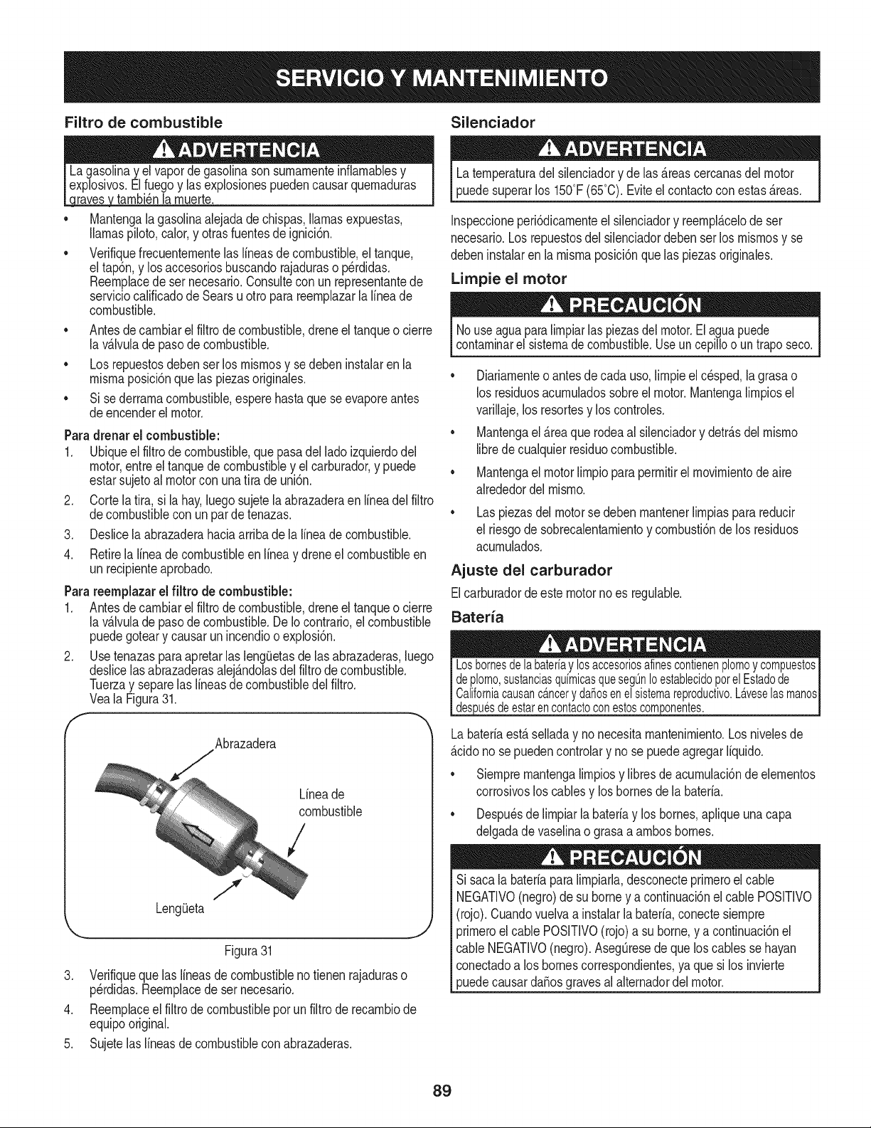
Filtro de combustible Silenciador
, tarnbi_nla rnuerte.
Mantengalagasolinaalejadade chispas,llamasexpuestas,
llamaspiloto,calor,y otrasfuentesde ignici6n.
Verifiquefrecuenternentelas lineasde combustible,el tanque,
el tap6n,y los accesoriosbuscandorajaduraso p@didas.
Reernplacede sernecesario.Consultecon un representantede
serviciocalificadode Searsu otto para reernplazarlalineade
combustible.
• Antesde carnbiarel filtro decombustible,dreneeltanqueo cierre
la v_lvulade pasode combustible.
• Los repuestosdebenser los rnisrnosy se debeninstalaren la
rnisrnaposici6nquelas piezasoriginales.
• Si sederrarnacombustible,esperehastaque seevaporeantes
deencenderel motor.
Paradrenar el combustible:
1. Ubiqueel filtro de combustible,que pasadel ladoizquierdodel
motor,entreel tanquede combustibley el carburador,y puede
estarsujetoalmotorcon unatira de uni6n.
2. Corte lafir& si la hay,luegosujetela abrazaderaen lineadel filtro
decombustiblecon unparde tenazas.
3. Deslicela abrazaderahaciaarriba dela lineade combustible.
4.
Retirela lineadecombustibleenlinea y dreneel combustibleen
un recipienteaprobado.
Parareemplazarel filtro de combustible:
1. Antesde carnbiarel filtro decombustible,dreneeltanqueo cierre
la v_.lvulade pasode combustible.DeIo contrario,elcombustible
puedegoteary causarun incendioo explosi6n.
2. Use tenazaspara apretarlas lengQetasde lasabrazaderas,luego
deslicelas abrazaderasalej&ndolasdel filtro de combustible.
Tuerzay separelas lineasde combustibledel filtro.
Veala Figura31.
Abrazadera
Lineade
combustible
/
.
4.
5.
J
LengQeta
J
Figura31
Verifiqueque laslineasde combustibleno tienenrajaduraso
p@didas.Reernplacede ser necesario.
Reernplaceel filtrode combustibleporun filtro de recarnbiode
equipooriginal.
Sujetelaslineasde combustiblecon abrazaderas.
Laternperaturadel silenciadory de las&teascercanasdel motor
puedesuperarlos 150°F(65°C).Eviteel contactoconestasAreas.
Inspeccioneperi6dicarnenteel silenciadory reernpl&celode ser
necesario.Los repuestosdel silenciadordeben serlos rnisrnosy se
debeninstalarenla rnisrnaposici6nquelas piezasoriginales.
Limpie el motor
Nouseaguaparalirnpiarlas piezasdelmotor.Elaguapuede
contarninarel sistemade combustible.Useun cepilloo un traposeco.
• Diariarnenteo antesde cadauso, lirnpieel cesped,lagrasao
los residuosacurnuladossobreel motor.Mantengalirnpiosel
varillaje,los resortesy los controles.
• Mantengael &reaquerodeaal silenciadory detr&sdel rnisrno
librede cualquierresiduocombustible.
• Mantengael motorlirnpioparaperrnitirel rnovirnientodeaire
alrededordelrnisrno.
Laspiezasdel motorse debenrnantenerlirnpiasparareducir
el riesgode sobrecalentarnientoy cornbusti6nde los residuos
acurnulados.
Ajuste del carburador
Elcarburadordeeste motorno es regulable.
Bateria
)uesdeestarencontactoconestoscomponentes.
Labateriaest&selladay no necesitarnantenirniento.Losnivelesde
&cidono se puedencontrolary nose puedeagregarliquido.
• Siernprernantengalirnpiosy libresde acurnulaci6nde elernentos
corrosivoslos cablesy los bornesde la bateria.
• Despu_sde lirnpiarlabateriay los bornes,apliqueunacapa
delgadade vaselinao grasaa arnbosbornes.
Si sacala bateriaparalirnpiarla,desconecteprirneroel cable
NEGATIVO(negro)de su borney a continuaci6nel cablePOSmVO
(rojo). Cuandovuelvaa instalarla bateria,conectesiernpre
prirneroel cable POSITIVO(rojo)a su borne,y a continuaci6nel
cable NEGATIVO(negro).AsegOresede que los cablesse hayan
conectadoa los bornescorrespondientes,ya quesi los invierte
puedecausardaSosgravesal alternadordel motor.
89
Nuncaalmacenela tractorcortacespedconcombustibleenel tanque
en unespaciocerradoo en a.reaspocoventiiadasdondelosgasesdei
combustiblepuedanIlegara unallamaexpuesta,unachispao un piloto
comoeiquetienenalgunoshornos,calentadoresde agua,secadores
de ropao aigQnartefactoa gas.
PREPARACION DEL MOTOR
IMPORTANTE:Elcombustiblequequedaen el tanquecuandohace
calorse deterioray causa problemasgravesde encendido.
Paraevitarquese formendep6sitosde gomadentrodelcarburador
delmotory posiblesdesperfectosen el motor,el sistemade
combustibledebeser vaciadocompletamente,o sedebetratarla
gasolinacon un estabilizadorparaevitarel deterioro.
Si utilizaunestabilizadorde combustible:
a. Lea las instruccionesy recomendacionesdel fabricantedel
producto.
b. Agreguela cantidadcorrectadeestabilizadorpara la
capacidaddelsistemadecombustiblea gasolinalimpiay
nueva.
c. Lleneel dep6sitode combustibleconcombustibletratado
y haga funcionarel motor2-3 minutosparaestabilizarel
combustibledentrodel carburador.
Cuandovacfeel sistemade combustible:
a. No dreneel combustiblecuandoel motorest,. caliente.
Permitaqueel motorseenfrfebien.Dreneel combustible
dentrode un recipienteaprobadoy al airelibre,lejosde
cualquierllamaexpuesta.
b. Dreneungran volumende combustibledesdeel dep6sito,
desconectandolaIfneade combustibledel filtro de
combustibleen Ifneaquese encuentracercadel motor.Vea
Paradrenarel combustibleenla p_.gina89.
Lagasolinaes sumamenteinflamabley puedesetexplosivaenciertas
condiciones.Vacfela antesde almacenarel equipoduranteperfodos
prolongados.Dreneel combustibleunicamentedentrodeun recipiente
aprobadoy al airelibre,lejosde cualquierllamaexpuesta.Dejeque
el motorse enfrfe.Antesdedrenarel combustible,apaguecigarrillos,
cigarros,pipasy otrasfuentesdecombusti6n.Almacenelagasolina
enun recipienteaprobado,en unlugarseguro.
c. Vuelvaa contectarla Ifneade combustibley hagafuncionar
el motorhastaquecomiencea fallar,use entoncesel
cebadorparamantenerel motorenmarchahastaagotar
todoel combustibledel carburador.
d. Desconectela Ifneade combustibley drene lagasolinaque
quedaen elsistema.
PREPARACI6N DEL TRACTOR CORTA CO:SPED
• Limpiey lubriqueperfectamenteel tractorcomose describe
en lasinstruccionesde lubricaci6n.
• No utiliceuna lavadoraa presi6no manguerade jardfnpara
limpiarsu unidad.
,, Almacenela unidaden una zonalimpiay seca.No la
almacenecercadeproductoscorrosivoscomoporejemplo
fertilizantes.
La gasolina es una sustancia t6xica. Elimineia gasolina adecuadamente.
Comunfquesecon las autoridadeslocales paraaveriguarcua.lesson los
metodos adecuadosparaeliminar la gasolina.
Extraigala bujfay vierta una(1)onza de aceiteparamotorporel
orificiode labujfa haciael interiordel cilindro.Hagagirarel motor
variasvecespara distribuirel aceite.Vuelvaa colocar labujfa.
9O
Antesde realizarcualquiertipode rnantenirnientooservicio.
desenganchetodosloscontrolesy detengael motor.Esperea quese
detengancornpletarnentetodaslaspiezasrn6viles.Desconecteelcable
dela bujfay p6ngalohaciendornasacontraelmotorparaevitarquese
enciendaaccidentalrnente.Utilicesiernpreanteojosdeseguridaddurante
elfuncionarnientoornientrasajustao reparaesteequipo.
En estaseccibnseanalizan problernasrnenores de servicio.Paraubicar el Centro de Servicio Sears rn_scercanoo paraprograrnar
un servicio,sirnplernentecornuniqueseconSears al tel_fono 1-800-4-MY-HOME®.
El motornoarranca 1. Perillade potenciade arranque(PTO)/
enganchede cuchillaconectada.
2. Noest,.colocadoel frenodernano.
3. Se ha desconectadoel cablede la bujfa.
4. La palancade controldel reguladorno est,.
enla posici6ndearranquecorrecta.
5. El tanquede combustibleest,. vacio oel
combustiblese ha echadoa perder.
6. La linea del combustibleest,. bloqueada.
El motorfuncionade rnanera
err_.tica
El motorrecalienta
7. La bujfano funcionacorrectarnente.
8. Motorahogado.
El motorvacilaa altas
revoluciones
El motorfuncionarnalen
rnarchalenta
Vibraci6nexcesiva
1. La unidadest,. funcionandoconel cebador
activado.
2. Loscablesde la bujiaest_.nfiojos.
3. La linea del combustibleest,. tapadaoel
combustiblese ha echadoa perder.
4. La ventilaci6nde la tapadel combustible
est,.obstruida.
5. Hayagua o suciedaden el sisternade
combustible.
6. El filtro de aireest,. sucio.
1. El nivelde aceitedel motorest,.bajo
2. Flujodeaire restringido
1. Pocaseparaci6ndeloselectrodosde labujia
1. La bujfade encendidoest,. sucia
2. El depuradorde aireest,. sucio
1. Lascuchillasde corteest_.nfiojaso
desbalanceadas
2. La cuchillade corte est,.da_ada,desafilada
odoblada
1. Coloquela perillaen la posici6nde desconexi6n
(OFF).
2. Coloqueel frenode rnano.
3. Conecteel cable a labujia.
4. Coloquela palancadel reguladoren la posici6n
FAST(r_.pido).
5. Lleneel dep6sitocon gasolinalirnpiay nueva(de
rnenosde30 dias).
6. Lirnpiela linea del combustible.Cornuniquesecon
Searsu otto distribuidorde serviciocalificado.
Reernplaceelfiltro de combustibleVea la secci6nde
Servicioy Mantenirniento.
7. Lirnpieo carnbiela bujia o ajustela separaci6n.
8. Arranqueel motorcon el reguladoren posici6n
FAST(velocidadr_.pida).
1. Verifiqueque el electricose estrangulatrabaja.
Cornuniquesecon Searsu otto distribuidorde
serviciocalificado.
.
3.
Conectey ajustelos cablesdela bujia.
Lirnpiela lineadelcombustible.Cornuniquesecon
Searsu otro distribuidordeserviciocalificado.
Lirnpiela lineadecombustible;Ileneel tanque
congasolinalirnpiay nuevay reernplaceel filtro
decombustible.Veala secci6nde Servicioy
Mantenirniento.
4. Destapela ventilaci6no reernplacela tapa si est,.
da_ada.
5. Vade el tanquedecombustible.Lleneel tanquecon
gasolinalirnpiay nueva.Vea la secci6nde Servicioy
Mantenirniento.
6. Reernplaceel elernentode papel deldepuradorde
aireo lirnpieel prefiltrodeespurna.
,
2.
Lleneelmotorconlacantidady tipodeaceiteadecuado.
Elirninelos recortesde cespedy los desechosde
alrededorde lasaletasde enfriarnientodel motory
delalojarnientodel soplador.
1. Extraigala bujiay regulela separaci6n.
1. Extraigala bujiay regulela separaci6n.
2. Reernplaceel elernentodel filtro deairey/o lirnpieel
depurador.
1. Aprietela cuchillay el husillo.Estabilicelacuchilla.
2. Reernplacelacuchilla.
91
Lacortadorade c_spedno
procesalos recortescomo
abono
Cortedesigual
1. La velocidaddel motores demasiadolenta.
2. Pastomojado.
3. C_speddemasiadoalto.
4. Lacuchillade la cortadoranoest£afilada.
1. La plataformano est,.correctamente
nivelada.
2. Cuchilladesafilada.
3. Presi6nde neum_.ticosdesigual.
1. Coloqueel control delestranguladoren laposici6n
FAST(velocidadr@ida, representadaporuna
liebre).
2. No proceseabonocuandoel pastoest,.mojado.
3. Corteuna vez con alturadecorteelevaday luego
vuelvaa cortarel c_speda laalturadeseada,o haga
unapasadade cortem_.sangosta.
4. Afile o cambiela cuchilla.
1. Hagaunajustede la plataformade lado a lado.
2. Afile o cambiela cuchilla.
3. Verifiquela presi6nde los cuatroneum_.ticos.
,NECESITAMASAYIDA?
Encontrar_ h l_espuesta y ross en ma_agemTbeme_em ° isin _ayge!
: ° ]_ste y los manua].esde todos sus otzos productos los encontraz_, en Hnea,
: ° Sus preguntas ser_.nzespondidas pot nuestzo equipo de especiahstas.
° Obtenga un p].ande mantenimiento personalizado paza su hogar.
° Encuentre informaci6n y hezramientas que !o ayudar_.n con ].ospzoyectos dom_sticos,
maHage home
f_ought to Fou by Sea_s
92
Felicitacionespor haberrealizadouna adquisici6ninteligente.El
productoCraftsman@que ha adquiridoest_ dise_adoy fabricado
parabrindarrnuchosa_osde funcionarnientoconfiable.Perocorno
todoslos productosa vecespuederequerirde reparaciones.Esen
esernornentocuandoel disponerde un Acuerdode protecci6npara
reparacionesle puedeahorrardineroy problernas.
A continuaci6nsedetallanlos puntosincluidosen el Acuerdo:
• Servicio experto prestadopor nuestros10,000especialistasen
reparacionesprofesionales
• Servicio ilirnitadosin cargoparalaspiezasy la rnanodeobra en
todaslas reparacionescubiertas
• Reernplazodel productohasta 1500d61aressi no es posible
repararel productocubierto
• Descuentode 10%del precionormaldel servicioy de las piezas
relacionadascon el rnisrnoqueno est_ncubiertasporel acuerdo;
adern&s,10%del precionormalde la verificaci6nde rnantenirniento
preventivo
• Ayudar_pidapot tel_fono- IoIlarnarnosResoluci6nR_pida- el
apoyotelef6nicode un Charnuscaal representante.Pienseen
nosotroscornoel manual"de undue_ohablador."
Unavezadquiridoel Acuerdo,puedeprograrnarel serviciocon
tan s61orealizarunaIlarnadatelef6nica.PuedeIlarnarencualquier
mornentodeldia o dela nocheo prograrnarun servicioen linea.
ElAcuerdode Protecci6nde Reparaci6nes unacornprasin riesgo.
Siustedanulaporalguna raz6nduranteel periodode garantiade
producto,proporcionarernosun reernbolsoIleno.O,un reernbolso
prorrateadoencualquiermornentodespu_sdel periodode garantia
de productoexpira,iAdquieraboysu acuerdode protecci6npara
reparaciones!
Seaplican deterrninadaslirnitaciones y exclusiones.Paraobtener
inforrnaci6nadicional y preciosen los Estados UnidosIlarne al
1-800-827-6655.
El*Coverage en Canad_variaen algunosarticulos. Paradetalles
Ilenosla IlarnadaCharnuscaCanad_en 1-800-361-6665.
Servicio de instalaci6nde Sears
Sideseasolicitarla instalaci6nprofesionalde Searsde aparatos
dorn_sticos,dispositivosparaabrir portones,calentadoresde agua
y otrosarficulosdorn_sticosirnportantes,en los EstadosUnidoso
Canad_Ilarneal 1-800-4-MY-HOME®.
93

94

95

Busque el periodo de duraci6n de emisiones importantes yla informaci6n de clasificaci6n de aire en
la etiqueta de emisiones de su motor
Los motores cuyo cumpiimiento con los estAndares de emisi6n Tier 2 de la Comisi6n de Recursos Ambientales de California (CARB)
est6 certificado deben exhibir la informaci6n relacionada con el periodo de duraci6n de ias emisiones y la clasificaci6n de aire. Sears
Brands Management Corporation ponen esta informaci6n a disposici6n del consumidor en nuestras etiquetas de emisiones.
Ei Periodo de Duraci6n de las Emisiones describe el nQmero de horas de tiempo real de funcionamiento para el cuai se certifica que
el motor cumpie con ias reglas de emisi6n, descontando el mantenimiento adecuado del mismo segQn las instrucciones de oper-
aci6n y mantenimiento. Se utilizan las siguientes categonas:
Moderado:Se certifica que el motor cumpie con las reglas de emisi6n durante 125 horas de tiempo real de funcionamiento del motor.
Inmediato:Se certifica que el motor cumpie con las reglas de emisi6n durante 250 horas de tiempo real de funcionamiento del motor.
Extendido:Se certifica que el motor cumpie con las reglas de emisi6n durante 500 horas de tiempo real de funcionamiento del motor.
Por ejemplo, una cortadora de c6sped tipica que se empuja desde arras se usa entre 20 y 25 horas por aSo. Por Io tanto, el Periodo
de Duraci6n de Emisiones de un motor con una clasificaci6n intermedia sena equivaiente a entre 10 y 12 aSos.
Laciasificaci6n de aire es un nQmero calculado para describir el nivel relativo de emisiones para un grupo de motores en particular.
Cuanto menor sea la clasificaci6n de aire, mayor es la limpieza del motor. La informaci6n se presenta de forma grAfica en la etiqueta
de emisiones.
Despu_s del 1 de julio de 2000, busque el periodo de cumplimiento de las reglas de
emisiones en la etiqueta de cumplimiento de las reglas de emisiones del motor
Despu6s del 1 de julio de 2000 se certificarA que determinados motores Sears Brands Management Corporation cumplen
con los estAndares de emisiones de la fase 2 de la Agencia de Protecci6n Ambientai de los Estados Unidos (USEPA). Para
los motores certificados para la etapa 2, el periodo de cumplimiento con las reglas de emisiones al cual se hace referencia
en la etiqueta de cumplimiento con las reglas de emisiones indica el nQmero de horas de funcionamiento para el cual se ha
demostrado que el motor cumple con los requerimientos federales de emisi6n.
Para los motores con desplazamiento inferior a 225 cc, Categoria C = 125 horas, B = 250 horas y A = 500 horas.
Para los motores con desplazamiento de 225 cc o mAs, Categoria C = 250 horas, B = 500 horas y A = 1000 horas.
El desplazamiento de los motores de la serie modelo 150112 es 249 cc.
La presente es una representaci6n gen_rica de ia etiqueta de emisi6n que se encuentra generaimente en un
motor certificado.
FAMILYYBSXS.3192VA 274812
GDOC-100182Rev.A
96

(Esta p_.ginase aplica s61oen EE.UU. y Canada.).
Sears Brands Management Corporation, el Consejo de Recursos Ambientales de California (CARB)
y la Agencia de Protecci6n Ambiental de los Estados Unidos (EPA)
Declaraci6n de garantia del sistema de control de emisiones (derechos y obligaciones de la garanfia de defectos del propi=
etario)
LA COBERTURADE LA GARANTJADE CONTROLDEEMISIONESES Y PARALOSMODELOSCERTIFICADOSDELANO 1997Y POSTERIORES,
APLIOABLEA LOS MOTORESCERTIFICADOSCOMPRADOSEN CALIFOR- QUESE COMPRENY UTILICENEN CUALQUIERPARTEDE LOSESTADOS
NIA EN1995Y POSTERIORMENTE,QUESE UTILIZANENCALIFORNIA, UNIDOS(Y A PARTIRDEL 1 DE ENERODE2001 EN CANADA).
Declaraci6n de garanfia sobre defectos en el control de emJsiones para California y los Estados UnJdos
ElConsejode RecursosAmbientalesde California(CARB),la EPA(Agencia
de Protecci6nAmbientalde los EE.UU.)y Searstienenel gusto de explicarla
garantiadel sistemade control de emisionespara motoresdela_o 2000y para
elfuturo con relaci6na motorespeque_ostodo terreno(SORE).En California,
los nuevosmotorespeque_ostodo terrenodebenestar dise_ados,construidos
y equipadosparacumplircon las rigurosasnormasanti-smogdelestado.En
el restode los EstadosUnidos,losmotoresnuevostodoterrenode encendido
porchispa certificadosparael a_o 1997debencumplirest_ndaressimilares
establecidospot la EPA.Sears debegarantizarel sistemade controlde emi-
sionesde su motorpara losperiodosde tiempoenumeradosa continuaci6n,
siemprequeno hayaabuso,negligenciao mantenimientoindebidode su
motortodoterrenopeque_o.Su sistemade controlde emisionespuedeincluir
piezastalescomoel carburador,el filtro de aire, elsistemade encendido,el
silenciadoryel conversorcatalitico.Tambienpuedeincluirconectoresy otras
unidadesrelacionadascon lasemisiones.Dondeexistaunacondici6ncubierta
por la garantia,Searsreparar_su peque6omotortodo terrenosin costoalguno
incluyendodiagn6stico,piezasy manodeobra
Cobertura de la garantJa Sears para defectos en el control de emJsiones
Los motorestodo terrenopeque6osest_ngarantizadosen Io relativoalcontrol alas disposicionesque se indiquena continuaci6n.Si una partede su motor
de emisionesparadefectosen piezasduranteun periodode dos a_os,sujeto cubiertapot lagaranfiaes defectuosa,Sears reparar_o sustituir_dichaparte.
Responsabilidades del propietario en relacibn con la garantia
Comopropietariodel motortodo terrenopeque_o,Ud.es responsablede la
realizaci6ndel mantenimientorequeridoquese incluyeen las instrucciones
de operaci6ny mantenimiento.Searsrecomiendaquese conserventodoslos
recibosrelativosal mantenimientode su motortodoterrenopeque_o,pero
no pude denegarla garantiasimplementepor la faltade los mismos,o por su
incumplimientodel mantenimientoprogramatic.Comopropietariodel motor
peque_otodoterrenodebe saberque, sinembargo,Sears lepuedenegar
lacoberturade lagarantiasi su motortodoterrenopeque6oouna piezadel
mismohanfalladodebido a abuso,negligencia,mantenimientoindebidoo
a modificacionesno aprobadas.Ud.es responsablede presentarsu motor
todoterrenopeque6oa un distribuidorde serviciosSearsautorizadotan pronto
comoaparezcaun problema.Las reparacionesde la garantiasinconfiicto
debencompletarseen un plazode tiemporazonable,no superiora 30 dias.Si
tienealguna preguntarespectoa sus derechosy responsabilidadesreferentes
a lagarantia,debe contactarcon un representantede serviciosSears al 1--
800--469--4663.La garantiade emisioneses unagarantiapotdefectos.Los
defectosse juzgande acuerdocon elfuncionamientonormalde un motor.La
garantiano est_relacionadacon unapruebade emisionesen uso.
Disposiciones de la garantJa Sears para defectos en el control de emJsiones
Las siguientesson disposicionesespecificasrelacionadascon la coberturade lagarantia paradefectosen el controlde emisiones.Esun a_adidoa lagarantiade
motorSearspara motoresno reguladosquese encuentraen lasinstruccionesde funcionamientoy mantenimiento.
1. Piezascon garantia
La coberturade esta garantiase extiendeL]nicamentea las piezas
queaparecena continuaci6n(las partesde los sistemasde control de
emisiones),siempreque dichas piezasestuvieranya en el motoren el
momentode su compra.
a. Sistemade medici6n de combustible
• Sistema de enriquecimientopara arranqueen frio
• Carburadory partesinternas
• Bombade combustible
b. Sistemade inducci6nde aire
• Filtrode aire
• Colector de admisi6n
c. Sistemadeencendido
• Bujia(s)de encendido
• Sistema de encendidomagneto
d. Sistemadelcatalizador
• Convertidorcatalitico
• Colector de escape
• Sistema de inyecci6nde aireo v_lvulade impulsos
e. Elementosvariadosusadosen lossistemasanteriores
• Wlvulas de vacio,sensiblesa temperatura,posici6ny tiempo
e interruptores
• Conectoresy montajes
2. AIcancede la cobertura
Searsgarantizaal poseedorinicialy a loscompradoressubsiguientes
quelas piezas con garantiano tendr_n defectosen materialesni mano
de obra que provoquenla falla de las mismasduranteun periodode
dos aSosa partirde la fechaen queel motorse entregaa un comprador
particular.
3. Sin cargo
La reparaci6no reemplazode cualquierpartecon garantia se realizar_
sin cargo alguno parael poseedor,incluyendotareasde diagn6sticoque
permitandeterminarsi una partecon garantiaes defectuosa,siempreque
dichodiagn6sticose realiceen un distribuidor de servicios Searsautoriza-
do. Parael servicio de lagarantia de emisiones,contacteal distribuidorde
serviciosSearsautorizadom_s cercanoincluidoen las"P_ginasamarillas"
en lascategorias"Motores,gasolina","Motoresde gasolina","Podadoras
de cesped",o similares.
4. Reclamacionesy exclusionesa la cobertura
Las reclamacionesde lagarantia debenenviarsede acuerdocon las
disposicionesde la politica de garantia para motoresSears. La cobertura
de lagarantia excluir_defectosen piezascongarantia queno sean partes
originalesSears,o abuso,negligenciao mantenimientoincorrecto,tal y
como se estableceen lapolitica de garantia para motoresSears.Sears no
es responsablede lasfallas en piezascon garantia provocadaspor el uso
de partesa_adidas,que no seanoriginaleso quese hayan modificado.
5. Mantenimiento
Cualquierpartecon garantiaque no esteprogramadaparaset reempla-
zadacomo mantenimientorequerido,o que s61odeba inspeccionarse
regularmentealefecto de "inspeccioneo reemplacesegL]nsea necesario",
estar_garantizadacontradefectosduranteel periodode la garantia.Todas
las piezasgarantizadasqueesten programadaspara su reemplazopara
cumplir con los requisitosde mantenimientoestar_ngarantizadass61o
por el periodoanterioral primerreemplazoprogramaticparadicha pieza.
Cualquierpiezade recambioquesea equivalenteen funcionamientoy
durabilidadpuedeusarse para realizarmantenimientoo reparaciones.El
propietarioes responsablede realizartodoel mantenimientorequerido,tal
y comose define en las instruccionesde funcionamientoy mantenimiento
Sears
6. Coberturaindirecta
Porla presente,la coberturase extiendea la falla de cualquiercomponente
de motorprovocadapot lafalla de unapieza con garantiaque estetodavia
en periodode garantia.
En los EstadosUnidosy Canad_hay unalinea de atenci6nde 24 horas,1-800-469--4GG3,quecuentacon un menL]con mensajespre-grabadosque contienen
informaci6npara el mantenimientode motores.

DECLARACIONFEDERALy/oDECALIFORNIASOBRE GARANTJAS EN EL CONTROL DE EIVIISIONES
SUS DERECHOS Y OBLIGACIONES EN CUANTO A LA GARANTJA
MTDConsumerGroupInc, laAgencia de Protecci6nMedioambientalde los EstadosUnidos(EPA),y paraaquellosproductoscertificadosparasu ventaen el es-
tadode California,el Departamentode los Recursosdel Aire de California(CARB)secomplacenen explicarla garanfiaque cubreal sistemade control(ECS)de
emisiones(evaporativasy/o de escape)de su equipoy motor(motorde equipos de exteriores)de encendidopot chispaparatodo terreno,peque_o,deexteriores
del a_o2006 y a_osposterioresEn California,losnuevosmotoresde equiposde exterioresdebenestar dise_ados,construidosyequipadospara cumplircon las
estrictasnormasantipoluci6ndel Estado(en otrosestados, losequipos del a_o 1997y modelosposterioresdebenserestar dise_ados,construidosy equipados
para cumplircon las regulacionesdemotoresde encendidopor chispa para todoterrenopeque_osde laAgencia de Protecci6nMedioambientalde los Estados
Unidos,(EPA).MTDConsumerGroupInc. debe garantizarel sistemade control de emisiones(ECS) de su motorde equipos de exteriorespot el periodode
tiempo indicadom_sabajo,siemprey cuando no existauso incorrecto,negligenciao mantenimientoinadecuadode dicho motor.
Su ECSpuedeincluir piezastales como el carburador,el sistemade inyecci6ndecombustible,el sistemade encendido,el convertidorcatalitico,losdep6sitos
de combustible,laslineas de combustible,lostaponesde combustible,lasv_lvulas,contenedores,filtros, manguerasde vapor, abrazaderas,conectoresy otros
componentesafinesrelacionadoscon lasemisiones.
Dondeexista unacondici6ncubiertapor la garantia,MTDConsumerGroupInc. reparar_su motorde equiposde exterioressincostoalgunoincluyendoel
diagn6stico,las piezasy la manode obra.
COBERTURA DE LA GARANTJA DEL FABRICANTE:
Este sistemade controlde emisionesse garantizaporel t@minode dos aSos.Si algunapiezarelacionadacon lasemisionesde su motorde equiposde
exterioreses defectuosa,MTDCONSUMERGROUPINC.reparar_o sustituir_dicha pieza.
RESPONSABILIDADES DEL PROPIETARIO SEGUN LA GARANTJA:
En su car_cterde propietariodel motorde equipos de exteriores,usted es responsabledel mantenimientorequeridoquese especificaen el manualdel propieta-
rio.MTDConsumerGroupInc le recomiendaque conservetodos losrecibos quecubrenel mantenimientode su motor,no obstanteIo cual MTDConsumerGroup
Inc no podr_denegarel cumplimientode lagarantia Qnicamentepor lafaltade los recibos.
Comopropietariodel motorde equiposde exteriores,usteddebe saber queMTDConsumerGroupInc. puededenegarlacoberturade lagarantia si su motoro
unapiezadel mismofallandebido a uso incorrecto,negligencia,mantenimientoindebidoo a modificacionesno aprobadas.
Ustedes responsablede presentarsu motoral centrode distribuci6no serviciotecnico de MTDConsumerGroupInc. tan prontocomo aparezcael problema.Las
reparacionescubiertaspor la garantiase debenIlevara caboen un lapsorazonableque no excedade 30 dias.Sitiene algunapreguntarespectode lacobertura
de la garantia,p6ngaseen contactocon el Departamentodel ServicioT@nicode MTDConsumerGroupInc. al telefono1-800-800-7310o pot correoelectr6nico
en http://support.mtdproducts.com
COBERTURA DE LA GARANTJA DE EMISIONES GENERALES:
MTDConsumerGroupIncgarantizaal compradorfinal y a cadacompradorsubsiguienteque el motorde equiposde exteriores:est_ dise_ado,construidoy
equipadode modo de cumplir contodas las regulacionesaplicablesy quese encuentralibre de defectosde materialesy de fabricaci6nque pudierencausarla
falla de una piezagarantizadaidentica,en todos losaspectosmaterialesa la pieza descriptaen la solicitudde certificaci6nde MTDConsumerGroup Inc.
El periodode garantiacomienzaen la fechade entregadel motoral compradorfinal o en lafecha en que la m_quinase pone en funcionamientopot primeravez.
El periodode garantiaes de dos aSos.
Sujetoa ciertas condicionesyexclusionesquese indicana continuaci6n,lagarantia de las piezas relacionadascon lasemisioneses la siguiente:
1. Cualquierpiezagarantizadaque no este programadaparaser reemplazadacomo partedel mantenimientorequeridoen lasinstruccionesescritassuminis-
tradasse garantizaporel periodo de garantiaarriba mencionado.Si la piezafalla duranteel periodo de coberturade lagarantia,la mismaser_reparada
o reemplazadapor MTDConsumerGroupInc. de acuerdo con el parrafo(4) a continuaci6n.Cualquierpiezareparadao reemplazadasegQnlagaranfia se
garantizar_potel resto del periodode garantia.
2. Cualquierpiezagarantizadaqueeste programadasolamenteparainspecci6nregularen las instruccionesescritassuministradassegarantiza pot el periodo
de garantia arribamencionado.Cualquierpiezareparadao reemplazadasegQnla garantiase garantizar_pot el restodel periodo.
3. Cualquierpiezagarantizadaqueeste programadapara reemplazosegQnel mantenimientorequeridode conformidadcon lasinstruccionesescritassuminis-
tradas,se garantizaporel periodode tiempo anteriora laprimerafecha de reemplazoprogramadapara esa pieza.Si la piezafalla antes del primerreemplazo
programado,la mismaser_ reparadao reemplazadapot MTDConsumerGroupInc. de acuerdo con el parrafo(4) a continuaci6n.Cualquierpiezareparadao
reemplazadabajogarantia se garantizar_pot el resto del periodoanterioral primerreemplazoprogramaticpuntualparaesa pieza.
4. La reparaci6no el reemplazode cualquierpieza garantizadade conformidadcon lasdisposicionesde lagarantia queaqui se estipulase deben realizaren un
centrode garantiasin costo alguno para el propietario.
5. Noobstantelas disposicionesque aquise estipulan,losservicios o reparacionesbajo garantiase suministrar_nen todos nuestroscentrosde distribuci6nbajo
franquiciade mantenimientopara los motoreso equiposen cuesti6n.
6. El propietariodel motorde equiposde exterioresno deber_pagarel trabajode diagn6sticodirectamenteasociadocon unapieza garantizadadefectuosaen
relaci6ncon las emisiones,siemprey cuando dichotrabajode diagn6sticose realiceen un centrocubiertopot lagarantia.
7. MTDConsumerGroupInces responsablepot da6os causadosa otros componentesde motoreso equiposderivadosde lafalla bajo garantiade cualquier
piezagarantizada.
8. Durantelatotalidaddelperiododegarantiadelmotoryequipoparatodoterrenoarribamencionado,MTDConsumerGroupIncmantendr_unsuministro
depiezasbajogarantiasuficienteparasatisfacerlademandaesperadadetalespiezas.
9. Cualquierpiezadereemplazosepodr_usarparaelcumplimientodelmantenimientoolasreparacionesbajogarantiaysesuministrar_nsincargopara
elpropietario.Dichousonoreducir_lasobligacionesdegarantiadeMTDConsumerGroupInc.
10.Nosepodr_nusarpiezasadicionalesnimodificadasquenoestenexentasdeacuerdoconelDepartamentodelosRecursosdelAire(AirResourcesBoard).
Elusodecualquierpiezaadicionalomodificadanoexentaporelcompradorfinalser_causaldeinvalidezdelosreclamosbajogaranfia.MTDConsumer
GroupIncnotendr_responsabilidadpotlagarantiadefallasdepiezasgarantizadasquefuerencausadaspotelusodeunapiezaadicionalnoexenta
omodificada.
PIEZAS GARANTIZADAS:
La reparaci6no el reemplazode cualquierpieza garantizadaquede otto modo pudieseestar cubiertapot la garantia podr_set excluidadetal coberturade
garantiasi MTDConsumerGroupIncdemuestraqueel motores objeto de uso incorrecto,negligenciao mantenimientoinadecuado,y que tal uso incorrecto,
negligenciao mantenimientoinadecuadofue causadirectade la necesidadde reparaci6no reemplazode dichapieza.No obstanteIo antedicho,cualquierajuste
de un componentecon un dispositivode limitaci6nde ajusteinstaladoen f_brica y quefuncioneadecuadamente,podr_set cubiertopot la garantia.Adem_s,
la coberturabajoestagarantiase extiendesolo a piezasqueestuvieronpresentesen el motory equipotodo terrenoadquiridos.
Est_ncubiertaslas siguientespiezascongaranfia para emisiones(decorresponder):
(1) Sistemade medici6nde combustible
• Sistemade mejorapara inicio en frio (cebadosuave)
• Carburadory piezasinternas(osistemade inyecci6npot combustible)
• Bombade combustible
• Dep6sitode combustible
(2) Sistemade inducci6nde aire
• Purificadordeaire
• Colectordeadmisi6n
(3) Sistemade encendido
• Bujia(s) deencendido
• Sistemade encendidopot magneto
(4) Sistemade encendido
• Convertidorcatalitico
• SAl(v_lvula Reed)
(5) Componentesvariosutilizadosen el sistemaanterior
• Wlvulas e interruptoresde vacio,temperatura,posici6nsensiblesal tiempo
• Conectoresy montajes
(6) Controlevaporativo
• Manguerade combustible
• Abrazaderasde la manguerade combustible
• Tap6ndel combustibleatado pot correa
• Cajadecarbono
• Lineas de vapor
GDOC-100223

Riding Equipment
questions or problems?
Satisfaction with your purchase
is our number one concern!
To troubleshoot problems,
get answers to questions, order parts,
or schedule repair service for your
Riding Equipment, call the number below.
Para respuestas a preguntas o problemas,
y ordenar piezas o pedir servicio para la
reparacibn de su equipo, Ilame el nt_mero abajo.
1-800-659-5917
Craftsman Help Line
www.craftsman.com
TM
® Registered Trademark / Trademark of KCD IP, LLC in the United States, or Sears Brands, LLC in other countries
® Marca Registrada / TMMarca de Fabrica de KCD IP, LLC en Estados Unidos, o Sears Brands, LLC in otros paises