
Loading ...
Loading ...
Loading ...
English
4
Minimum gauge for Cord sets
Volts
Total length of Cord in Feet
(meters)
120 V 25 (7.6) 50 (15.2) 100 (30.5) 150 (45.7)
240 V 50 (15.2) 100 (30.5) 200 (61.0) 300 (91.4)
Ampere Rating
American Wire gauge
More
Than
not
More
Than
0 6 18 16 16 14
6 10 18 16 14 12
10 12 16 16 14 12
12 16 14 12 Not Recommended
The label on your tool may include the following symbols. The
symbols and their definitions are asfollows:
V ......................... volts
Hz .......................hertz
min ..................... minutes
or DC ......direct current
...................... Class I Construction
(grounded)
…/min ..............per minute
BPM .................... beats per minute
IPM ..................... impacts per minute
RPM .................... revolutions per
minute
sfpm ................... surface feet per
minute
SPM .................... strokes per minute
A ......................... amperes
W ........................watts
or AC ...........alternating current
or AC/DC .... alternating or
direct current
...................... Class II
Construction
(double insulated)
n
o
.......................no load speed
n .........................rated speed
......................earthing terminal
.....................safety alert symbol
.....................visible radiation
..................... wear respiratory
protection
..................... wear eye
protection
..................... wear hearing
protection
..................... read all
documentation
SAVE THESE INSTRUCTIONS FOR
FUTURE USE
Motor
Be sure your power supply agrees with the nameplate
marking. Voltage decrease of more than 10% will cause loss
of power and overheating.
DeWALT
tools are factory tested;
if this tool does not operate, check power supply.
COMPONENTS (Fig. A)
WARNING: Never modify the power tool or any part
of it. Damage or personal injury couldresult.
Refer to Figure A at the beginning of this manual for a
complete list ofcomponents.
Intended Use
These heavy-duty rotary hammers have been designed for
professional hammerdrilling, and chipping at various work
sites (i.e., construction sites).
DO nOT use under wet conditions or in presence of
flammable liquids orgases.
These heavy-duty rotary hammers are professional
powertools. DO nOT let children come into contact with
the tool. Supervision is required when inexperienced
operators use thistool.
ASSEMBLY AND ADJUSTMENTS
WARNING: To reduce the risk of serious personal
injury, turn unit off and disconnect it from
power source before making any adjustments or
removing/installing attachments or accessories.
An accidental start-up can causeinjury.
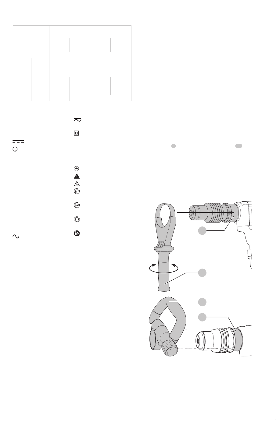
Side Handle (Fig. A, B)
WARNING: To reduce the risk of personal injury,
ALWAYS operate the tool with the side handle
properly installed and securely tightened. Failure to do
so may result in the side handle slipping during tool
operation and subsequent loss of control. Hold tool
with both hands to maximizecontrol.
The side handle
3
clamps to the mounting area
12
of the
gear case and may be rotated 360˚ to permit right- or left-
hand use. The side handle must be tightened sufficiently to
resist the twisting action of the tool if the accessory binds
or stalls. Be sure to grip the side handle at the far end to
control the tool during astall.
To loosen side handle, rotatecounterclockwise.
D25604, D25652
12
Fig. B
3
D25831, D25851
3
12
Loading ...
Loading ...
Loading ...