Loading ...
Loading ...
Loading ...
4
- All Other Markets:
NOTE:
(*) Measure burner operating pressure at manifold test point with two burners operating at the 'High
Flame' setting.
NAT, LPG & Butane Only - Operating pressure is ex-factory set and is not to be adjusted, apart from
when converting between gases, if required. (Refer to ‘Gas Conversion’ section for further details).
(**) TOWN GAS Only - Burner operating pressure is to be adjusted using the adjustable gas regulator
supplied.
Refer to the ‘Gas Conversion and Specifications’ section in this manual for further details.
Cabinet Models;
Gas supply connection point is located at rear of appliance, approximately 130mm from right hand side and
655mm from floor. It is reached from beneath the appliance. (Refer to ‘Dimensions’ drawings).
Benchtop Models;
Gas supply connection point is located at rear of appliance, approximately 130mm from right hand side and
60mm from floor. It is reached from beneath the appliance. (Refer to ‘Dimensions’ drawings).
Connection is ¾" BSP male thread (for all models).
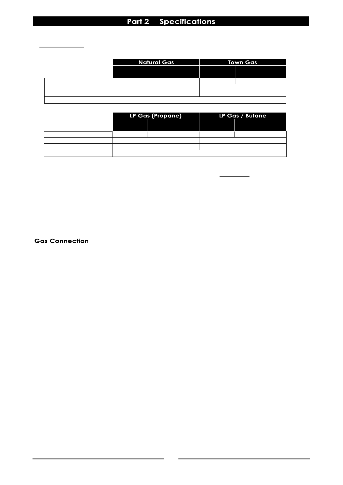
Open Burner
(each)
Griddle
(each 300mm section)
Open Burner
(each)
Griddle
(each 300mm section)
Input Rate (N.H.G.C.)
22 MJ/hr 20 MJ/hr 22 MJ/hr 20 MJ/hr
Supply Pressure
2.75 - 4.50 kPa 2.75 - 4.50 kPa
Burner Operating Pressure (*)
2.6 kPa 2.6 kPa
Gas Connection
¾” BSP Male
Open Burner
(each)
Griddle
(each 300mm section)
Open Burner
(each)
Griddle
(each 300mm section)
Input Rate (N.H.G.C.)
22 MJ/hr 20 MJ/hr 22 MJ/hr 20 MJ/hr
Supply Pressure
1.13 - 3.40 kPa 0.75 - 1.50 kPa
Burner Operating Pressure (*)
1.0 kPa 0.63 kPa
Gas Connection
¾” BSP Male
Loading ...
Loading ...
Loading ...