
Owner's Manual
ICRRFTSMRWJ
18.0 HP
ELECTRIC START
42" MOWER
AUTOMATIC
LAWN TRACTOR
Model No.
917.272421
• Safety
• Assembly
• Operation
• Maintenance
• Repair Parts
CAUTION:
Read and follow all Safety
Rules and Instructions before
operating this equipment,
For answers toyourquestions
about thisproduct,Call:
1-800-659-5917
Sears Craftsman Help Line
5 am- 5 pro, Mon- Sat
Sears, Roebuck and Co., Hoffman Estates, II 60179
Visit our Craftsman website:www.sears.corn/cre:ffsman
Warranty...............................................2
Safety Rules ......................................... 3
Product Specifications.......................... 6
Assembly .............................................. 8
Operation ............................................ 11
Maintenance ....................................... 18
Maintenance Schedule ...................... 18
Service and Adjustments.................... 23
Storage ............................................... 29
Troubleshooting ................................. 30
Repair Parts........................................ 34
Parts Ordering ..................... Back Cover
LIMITED TWO YEAR WARRANTY ON CRAFTSMAN RIDING EQUIPMENT PARTS
For two (2) years from the date of purchase, if this Craftsman Riding Equipment is
maintained, lubricated and tuned up according to the instructions in the owner's
manual, Sears will repair or replace, free of charge, any parts found to be defective in
matedal or workmanship. Warranty service is available free of charge by returning
your Craftsman riding equipment to your nearest Sears Service Center. In-home
warranty service is available but a trip charge will apply. This warranty applies only
while this product is in the United States.
This Warranty dees not cover:
• Expendable items which become worn during normal use, such as blades, spark
plugs, air cleaners, belts and oil filters.
• Tire replacement or repair caused by punctures from outside objects, such as nails,
thorns, stumps, or glass.
• Repairs necessary because of operator abuse, includingbut not limited to, damage
caused by towing objects beyond the capability of the riding equipment, impacting
objects that bend the frame or crankshaft, or over speeding the engine.
• Repairs necessary because of operator negligence, includingbut not limitedto,
electrical and mechanical damage caused by improper storage, failure to use the
proper grade and amount of engine oil, failure to keep the deck clear of flammable
debris, or the failure to maintain the equipment according to the instructions
contained in the owner's manual.
• Engine (fuel system) cleaning or repairs caused by fuel determined to be contami-
nated or oxidized (stale). In general, fuel should be used within thirty (30) days of its
purchase date.
• Riding equipment used for commercial or rental purposes. A product is "used for
commercial purpose" if is used for any purpose other than single family household
dwellings or in usage where profit is made.
LIMITED 90 DAYWARRANTY ON BA'I-rERY
For ninety (90) days from date of purchase, if any battery included with this riding
equipment proves defective in material or workmanship and our testing determines
the battery will not hold a charge, Sears will replace the baftery at no charge. War-
ranty service is available free of charge by returning your Craftsman riding equipment
to your nearest Sears Service Center. In-home warranty service Is available but a trip
charge will apply. This warranty applies only while this product is in the United States.
TO LOCATE THE NEAREST SEARS SERVICE CENTER OR TO SCHEDULE IN-
HOME WARRANTY SERVICE, SIMPLY CONTACT SEARS AT t-800-4-MY-HOME
This Warranty gives you specific legal dghts, and you may also have other rights
whichmay vary from state tostate.
Sears, Roebuck and Co., D/817 WA, Hoftman Estates, IL 60179
2
IMPORTANT: This cutting machine is capable of amputating hands and feet and
throwingobjects, Failure to observe the following safety instructionscould result in
sedous injuryor death.
I. GENERAL OPERATION
• Read, understand, and follow all
instructionsin the manual and on the
machine before starting.
• Only allow responsibleadults, who are
familiarwith the instructions,to operate
the machine.
• Clear the area of objects suchas
rocks,toys, wire, etc., whichcould be
picked up and thrown by the blade.
• Be sure the area is clear of other
people before mowing. Stop machine
if anyone enters the area.
• Never carry passengers.
• Do not mow in reverse unlessabso-
lutely necessary. Always look down
and behind before and while backing.
• Be aware ofthe mower discharge
directionand do not point it at anyone.
Do not operate the mower without
either the entire grass catcher or the
guard in place.
• Slow down before turning.
• Never leave a runningmachine
unattended, Always tum off blades, set
parking brake, stop engine, and
remove keys before dismounting.
• Turn off blades when not mowing.
• Stop engine before removing grass
catcher or uncloggingchute.
• Mow only in daylightor good artificial
light.
• Do not operate the machine while
under the influence of alcohol or drugs.
• Watch for traffic wt_en operating near or
crossing roadways.
• Use extra care when loading or
unloading the machine into a trailer or
truck.
• Data indicates that operators, age 60
years and above, are involvedin a
large pementaga of dding mower.
related injuries. These operators
should evaluate their ability to operate
the ddingmower safely enough to
protect themselves and others from
sedous injury.
• Keep machinefree of grass, loaves or
other debds build-upwhich can touch
hotexhaust / engine parts and bum. Do
notallow the mower deck to plow leaves
or other debris whichcan cause build-
upto occur.
Clean any oil or fuel
spillage before operating or storingthe
machine. Allowmachine to coolbefore
storage.
II, SLOPE OPERATION
Slopes are a major factor related to loss-
of-control and tipover accidents, which
can resultin severe injury or death. All
slopes require extra caution. If you
cannot back up the slope or ifyou feel
uneasy on it, do not mow it.
DO:
• Mow up end down slopes, not across.
• Remove obstacles such as rocks,tree
limbs,etc.
Watch for holes, ruts, or bumps.
Uneven terrain could overturn the
machine. Tall grass can hide obstacles.
Use slow speed. Choose a low gear
so that you willnot have to stop or shift
while on the slope.
Follow the manufacturer's recommen-
dationsfor wheel weights or counter-
weights to improve stability.
Use extra care with grass catchers or
other attachments. These can change
the stability of the machine.
Keep all movement on the slopes slow
and gradual Do not make sudden
changes in speed or direction.
Avoid starting or stoppingon a slope. If
tires lose traction, disengage the
blades and proceed slowly straight
down the slope.
DO NOT:
• Do not turn on slopes unless neces-
sary, and then, turn slowly and gradu-
ally downhill, if possible.
• Do not mow near drop-offs, ditches, or
embankments. The mower could
suddenly turn over if a wheel isover
the edge of a cliff or ditch, or if an edge
caves in.
• Do notmow on wet grass. Reduced
traction could cause sliding.
• Do not try to stabilizethe machine by
puttingyour foot on the ground.
• Do notuse grass catcher on steep
slopes.
3
III. CHILDREN
Tragic accidents can occurif the operator
is not alert to the presence of children.
Childrenare often attracted to the
machine and the mowing activity. Never
assume that children will remain where
you last saw them.
• Keep children out of the mowing area
and under the watchfulcare of another
responsible adult.
• Be alert and turn machine off if children
enter the area.
• Before and when backing, look behind
and down for small children.
• Never carry children. Tbey may fall off
and be sadously injured or interfere
with safe reach'me operation.
• Never allow children to operate the
machine.
• Use extra care when approaching blind
comers, shrubs, trees, or other objects
that may obscure vision.
IV. SERVICE
• Use extra care in handling gasoline
and other fuels. They are flammable
and vapors are explosive.
-Use only an approved container.
-Never remove gas cap or add fuel
with the engine running. Allow
engine to cool before refueling. Do
not smoke.
-Never refuel the machine indoors.
- Never store the machine or fuel
container inside where there is an
open flame, such as a water heater.
• Never run a machine inside a closed
area.
• Keep nuts and bolts, especially blade
attachment bolts, tight and keep
equipment in good condition.
• Never tamper with safety devices.
Check their proper operation regularly.
• Keep machine free of grass, leaves, or
other debds build-up. Clean oil or fuel
spillage. Allow machine to cool before
stodng.
• Stop and inspectthe equipment if you
strike an object. Repair, if necessary,
before restarting.
• Never make adjustments or repairs
with the engine running.
• Grass catcher components are subject
to wear, damage, and deterioration,
which could expose moving parts or
allow objects to be thrown. Frequently
check components and replace with
manufacturer's recommended parts,
when necessary.
• Mower blades are sharp and can cut.
Wrap the blade(s) or wear gloves, and
use extra caution when servicing them.
• Check brake operation frequently.
Adjust and service as required.
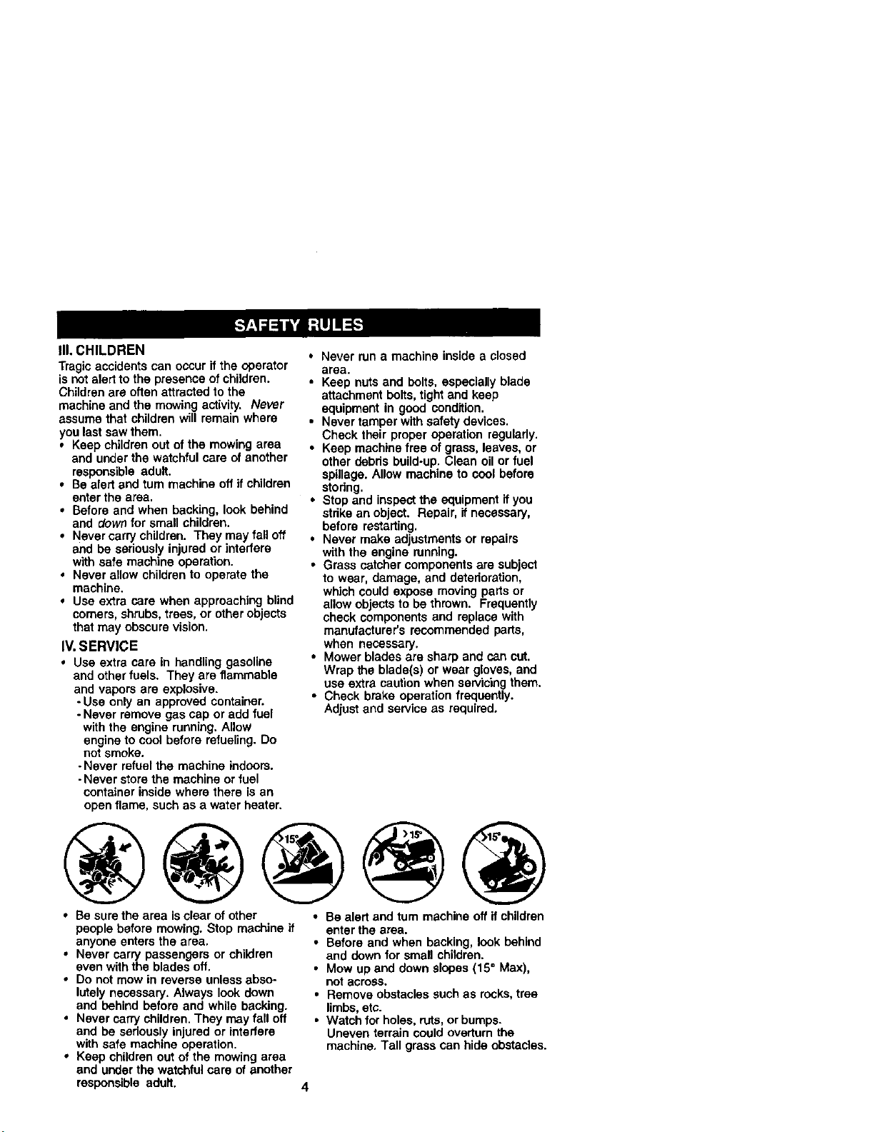
• Be sure the area isdear of other
people before mowing. Stop machine if
anyone enters the area.
• Never carry passengers or children
even with the blades off.
• Do not mow in reverse unless abso-
lutely necessary. Always look down
and behind before and while backing.
• Never carry children. They may fall off
and be seriously injured or interfere
with safe machine operation.
• Keep children out of the mowing area
and under the watchful care of another
responsible adult.
• Be alert and turn machine off if children
enter the area.
• Before and when backing, look behind
and down for small children.
• Mow up and down slopes (15° Max),
not across.
• Remove obstacles such as rocks,tree
limbs, etc.
• Watch for holes, ruts, or bumps.
Uneven terrain could overtum the
machine, Tall grass can hide obstacles.
• Use slow speed. Choose a low gear so
that you will not have to stop or shift
while on the slope.
• Avoid starting or stopping on a slope. If
tires lose traction, disengage the
blades and proceed slowly straight
down the slope.
• If machine stops while going uphill,
disengage blades, shift into reverse
and back down slowly.
• Do not turn on slopes unless neces-
sary, and then, turn slowly and gradu-
ally downhill,if possible.
_l_Look for this symbol to point out
importantsafety precautions. It means
CAUTION!!I BECOMEALERT!!I YOUR
SAFETY IS INVOLVED.
_. CAUTION: In order to prevent
accidental startingwhen setting up,
transporting, adjusting or making repairs,
always disconnect spark plug wire and
place wire where it cannot contact spark
plug.
_& CAUTION: Do not coast down a hill
in neutral, you may lose control of the
tractor.
CAUTION: Tow only the attachments
that are recommended by and comply
with specificationsof the manufacturer of
your tractor. Use common sense when
towing. Operate only at the lowest
possible speed when on a slope. Too
heavy of a load, while on a slope, is
dangerous. Tires can lose tractionwith
the ground and cause you to lose control
of yourtractor.
_WARNING: Engine exhaust, some of
its constituents, and certain vehicle
components contain or emit chemicals
known to the State of Californiato cause
cancer and birth defects or other repro-
ductive harm.
_WARNING: Battery posts, terminals
and related accessodes contain lead and
lead compounds, chemicals knownto the
State of California to cause cancer and
birth defects or other reproductiveharm.
Wash hands after handling.
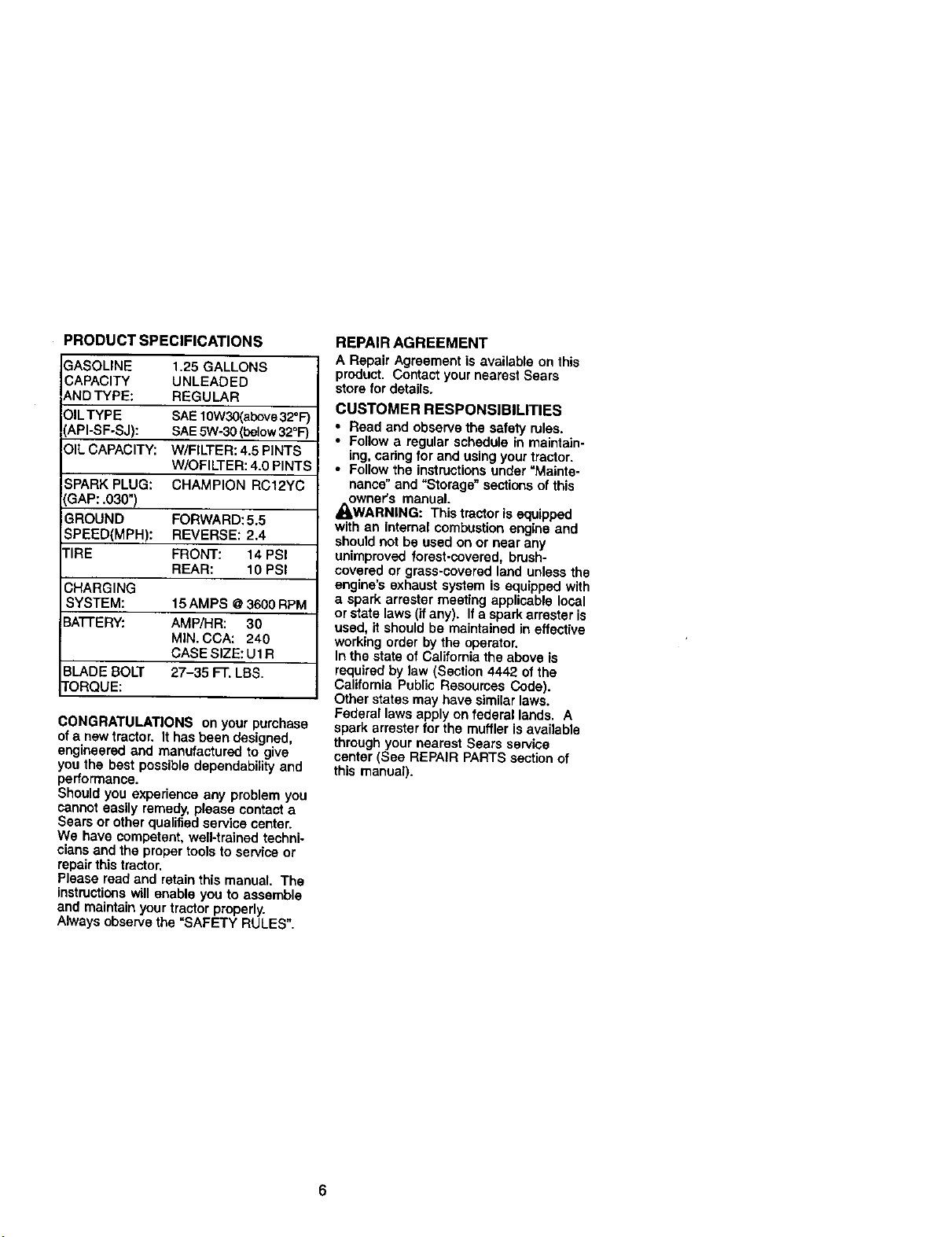
PRODUCTSPECIFICATIONS
GASOLINE 1.25GALLONS
CAPACITY UNLEADED
ANDTYPE: REGULAR
OILTYPE SAEt 0W30(abovs32°F)
API-SF-SJ): SAE5W-30 (below320F")
OIL CAPACITY: W/FILTER: 4.5 PINTS
W/OFILTER: 4.0 PINTS
SPARK PLUG: CHAMPION RC12YC
GAP: .030")
GROUND FORWARD: 5,5
SPEED(MPH): REVERSE: 2,4
TIRE FRONT: 14 PSI
REAR: 10 PSI
_HARGING
SYSTEM: 15 AMPS @3600 RPM
3A'I-rERY: AMP/HR: 30
MIN. COA: 240
CASE SIZE: U1 R
BLADE BOLT 27-35 FT. LBS.
tORQUE:
CONGRATULATIONS on your purchase
of a new tractor. It has been designed,
engineered and manufactured to give
you the best possible dependability and
performance.
Shoutd you experience any problem you
cannot easily remedy, please contacta
Sears or uther qualifiedservice center.
We have competent, well-trainod techni-
cians and the proper tools to service or
repair this tractor,
Please read and retain this manual, The
Instructionswill enable you to assemble
and maintain yourtractor properly.
Always observe the =SAFETY RULES".
REPAIR AGREEMENT
A Repair Agreement is available on this
product, Contact your nearest Sears
storefor details.
CUSTOMER RESPONSIBILITIES
• Read and observethe safety rules.
• Follow a regular schedule in maintain-
ing, cadng for and using your tractor.
• Follow the instructionsunder =Mainte-
nance" and "Storage" sections ofthis
owner's manual.
/I=WARNING: This tractor is equipped
with an internal combustion engine and
should not be used on or near any
unimproved forest-covered, brush-
covered or grass-covered land unless the
engine's exhaust system is equipped with
a spark arrester meeting applicable local
or state laws (if any). If a spark arrester is
used, it should be maintained in effective
working order by the operator.
In the state of California the above is
required by law (Section 4442 of the
California Public Resources Code).
Other states may have similar laws.
Federal laws apply on federal lands. A
spark arrester for the muffler is available
through your nearest Sears service
center (See REPAIR PARTS section of
this manual).
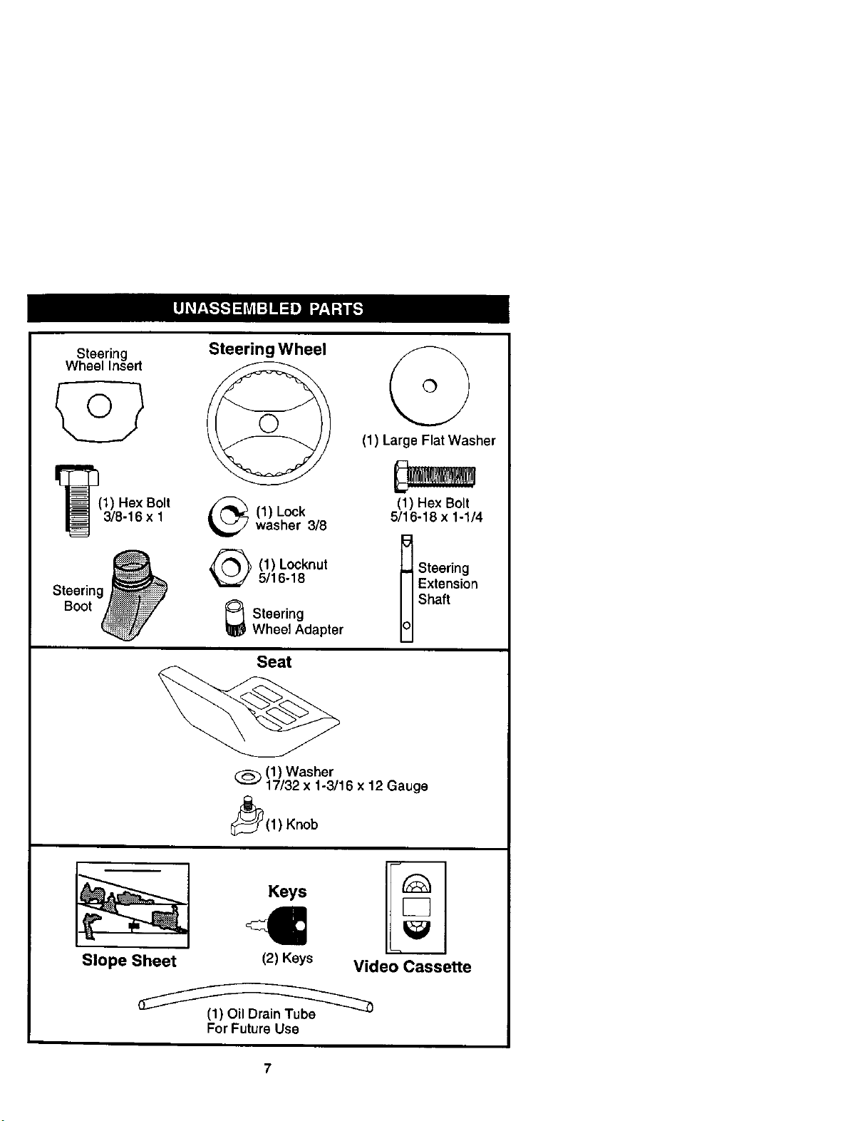
Steering
Wheel Insert
I_(1) Hex Bolt
3/8-16 x 1
Steering _
Boot
Steering Wheel
(1) Lockwasher 3/8
(1) Locknut
5/16-18
_ Steering
Wheel Adapter
Seat
(1) Large Flat Washer
(1) Hex Bolt
5/16-18 x 1-1/4
t St)terni;igon
Shaft
(_ (1) Washer
17/32 x 1-3/16 x 12 Gauge
_(1 ) Knob
Slope Sheet
Keys
(2) Keys Video Cassette
For Future Use
Your new tractor has been assembled at the factory with exceptionof those parts left
unassembled for shipping purposes. To ensure safe and propar operation of your
tractor all parts and hardware you assemble must be tightened securely.Use the
correct tools as necessary to insure proper tightness. Review the video cassette before
you begin.
TOOLS REQUIRED FOR ASSEMBLY
A socket wrench set will make assembly
easier. Standard wrench sizes you need
are listed below.
(1) 9/16" wrench (1) Pliers
(2) 1/2" wrench (1) Utility knife
(1) Tire pressure gauge
When rightor left hand is mentioned in
this manual, itmeans, from your pointof
view, when you are in the operating
position (seated behind the steering
wheel)•
TO REMOVETRACTOR FROM
CARTON
UNPACK CARTON
1. Remove all accessible loose parts
and parts cartons from carton.
2. Cut, from top to bottom, along lines on
all four comers of carton, and lay
panels flat.
3. Check for any additional loose parts
or cartons and remove.
BEFORE REMOVINGTRACTOR
FROM SKID
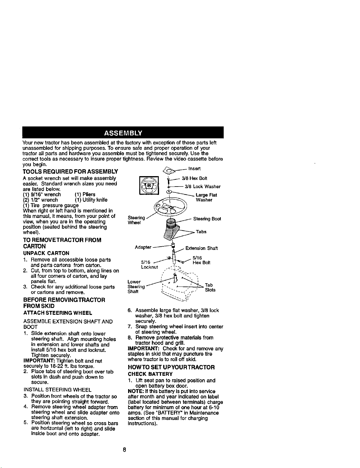
A'rrACH STEERING WHEEL
ASSEMBLE EXTENSION SHAFT AND
BOOT
1. Slide extension shaft onto lower
steedng shaft. Align mounting holes
in extension and lower shafts and
install 5/16 bex bolt and leoknut.
Tighten securely.
IMPORTANT: Tighten boltand nut
securely to 18-22 ft. Ibstorque.
2. Place tabs ofsteoring boot over tab
slots in dash and push down to
secure•
INSTALL STEERING WHEEL
3. Position front wheels of the tractor so
they are pointingstraight forward.
4. Remove steering wheel adapter from
steedng wheel and slide adapter onto
steering shaft extension.
5. Position steering wheel so cross bars
are horizontoi(left to right) and slide
inside boot and onto adapter.
___.__- Insert
_-- 3/8HexBolt
3/8 LockWasher
LargeFlat
Washer
• 5/16
5/16 Hex Boll
Locknut ._ ",,
Lower _ _
' Tab
_.eenh_ ..
Shaft <._ ' Slots
6. Assemble large flat washer, 3/8 lock
washer, 3/8 hex bolt and tighten
securely.
7. Snap steering wheel insert into center
of steering wheel.
8. Remove protective materials from
tractor hood and grill.
IMPORTANT: Check for and remove any
staples in skid that may puncture tire
where tractor isto rolloff skid.
HOWTO SET UPYOURTRACTOR
CHECK BATTERY
1. Lift seat pan to raised positionand
open battery box door.
NOTE: Ifthis batteryis put intoservice
after month and year indicated on label
(label located between terminals) charge
battery for minimum of one hour at 6-10
amps. (See "BATTERY" in Maintenance
section of this manual for charging
instructions).
8
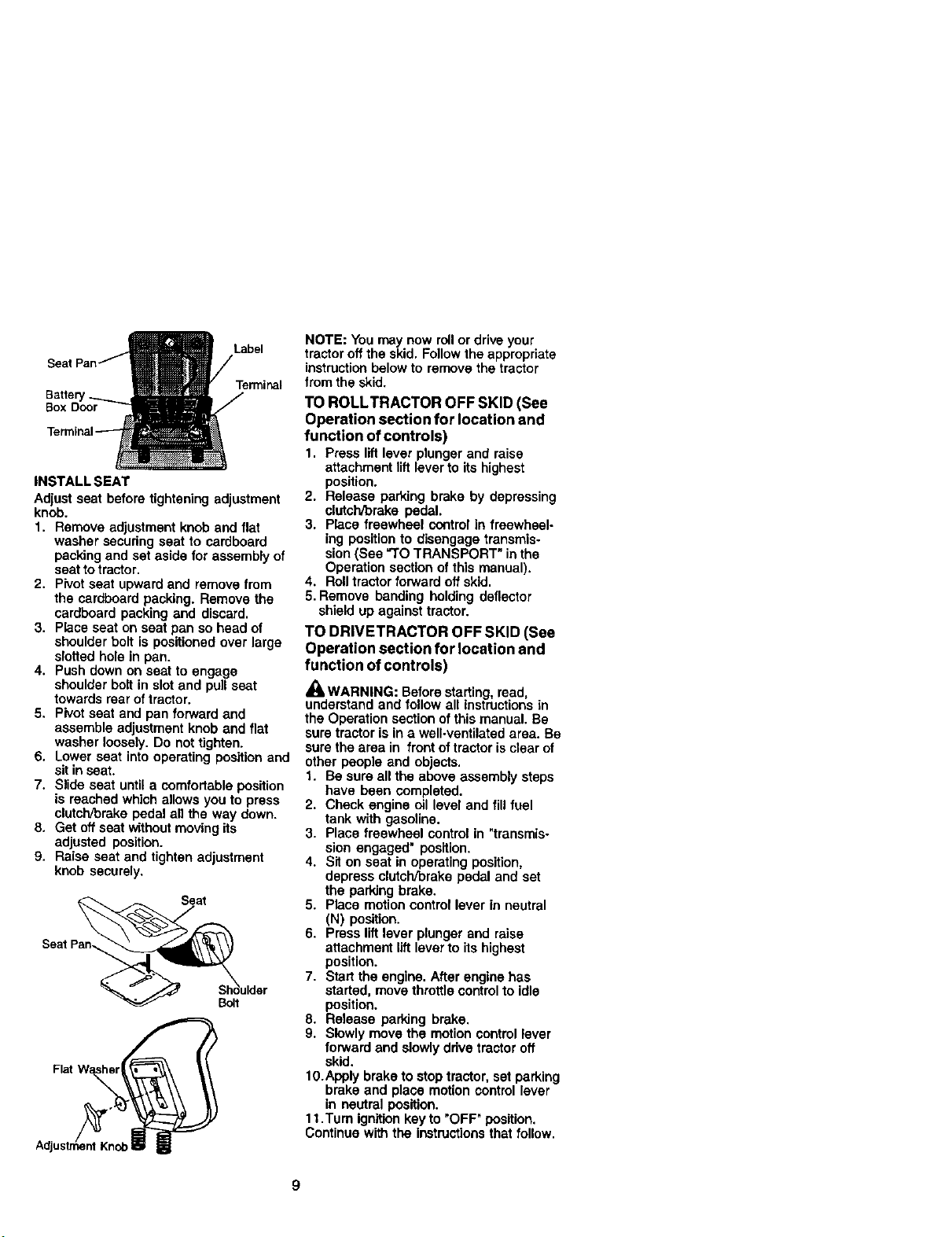
Label
Box Door
Terminal
INSTALL SEAT
Adjust seat before tightening adjustment
knob.
1. Remove adjustment knob and flat
washer securing seat to cardboard
packing and set aside for assembly of
seat to tractor.
2. Pivot seat upward and remove from
the cardboard packing. Remove the
cardboard packing and discard.
3. Place seat on seat pan so head of
shoulder bolt is positioned over large
slotted hole in pan.
4. Push down on seat to engage
shoulder boll in slot and pull seat
towards rear of tractor.
5. Pivot seat and pan forward and
assemble adjustment knob and flat
washer loosely. Do not tighten.
6. Lower seat into operating position and
sit in seat.
7. Slide seat until a comfortable position
is reached which allows you to press
clutch/broke pedal ait the way down.
8. Get off seat withoutmovingits
adjusted position.
9. Raise seat and tighten adjustment
knob securely.
Seat Pan_ulder
Flat
NOTE: You may now rollor drive your
tractor oft the skid. Follow the appropriate
instructionbelow to remove the tractor
from the skid.
TO ROLLTRACTOR OFF SKID (See
Operation section for location and
function of controls)
1. Press lift lever plunger and raise
attachment liftlever to its highest
position.
2. Release parking brake by depressing
clatch/10rakepedal.
3. Place freewheel control in freewheel-
ing position to disengage transmis-
sion(See "TO TRANSPORT" in the
Operation section of this manual).
4. Rolltractor forward off skid.
5. Remove banding holding deflector
shield up against tractor.
TO DRIVETRACTOR OFF SKID (See
Operation section for location and
function of controls)
_WARNING: Before starting read,
understand and fo low all instructionsin
the Operation section ofthismanual. Be
sure tractoris in a well-ventilated area. Be
sure the area in front of tractor is clear of
other people and objects.
1. Be sure all the above assembly steps
have been completed.
2. Check engine oil level and fill fuel
tank with gasoline.
3. Place freewheel control in "transmis-
sion engaged" position.
4. Sit on seat in operating position,
depress clutch/brake pedal and set
the parkJngbrake.
5. Place motion control lever in neutral
(N) position.
6. Press lift lever plunger and raise
attachment liftlever to its highest
position.
7. Start the engine. After engine has
started, move throttle controlto idle
position.
8. Release parking brake.
9. Slowly move the motion control lever
forward and slowly drive tractoroff
skid.
1O.Apply brake to stop tractor, set parking
brake and place motion control lever
in neutral position.
1t .Turn ignitionkeyto "OFF" position.
Continue with the instructionsthat follow.
9
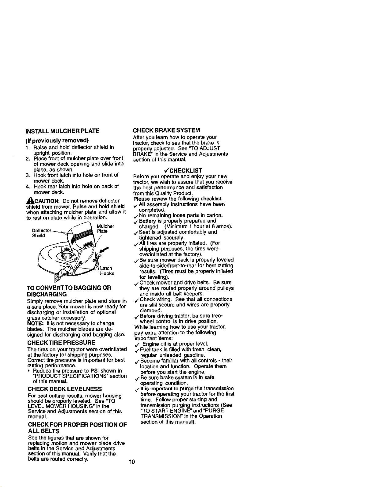
INSTALLMULCHERPLATE
(If previously removed)
1. Raise and hold deflector shield in
upright position.
2. Place front of mulcher plate over front
of mower deck opening and slide into
place, as shown.
3. Hook front latch into hole on front of
mower deck.
4. Hook rear latch into hole on back of
mower deck.
AOACAUTION: Do not remove
deflector
shield from mower. Raise and hold shield
when attaching mulcher plate and allow it
to rest on plate while in operation.
Mulcher
Plate
Shield
Hooks
TO CONVERTTO BAGGING OR
DISCHARGING
Simply remove mulcher plate and store in
a safe place. Yourmower is now ready for
discharging or installation of optional
grass catcher accessory.
NOTE: It isnot necessary to change
blades. The mulcher blades are de-
signed for discharging and bagging also.
CHECKTIRE PRESSURE
The tires on your tractor were overinflated
at the factory for shipping purposes.
Correcttire pressure is important for best
cutting performance.
• Reduce tire pressure to PSI shown in
=PRODUCT SPECIFICATIONS" section
of this manual.
CHECK DECK LEVELNESS
For best cuttingresults, mower housing
should be properly leveled. See "TO
LEVEL MOWER HOUSING inthe
Service and Adjustments section of this
manual.
CHECK FOR PROPER POSITION OF
ALL BELTS
See the figuresthat are shownfor
replacing motion and mower blade drive
bells in the Service and Adjustments
sectionofthis manual. Verify that the
bells are routed correctly.
CHECK BRAKE SYSTEM
Afteryou learn how to operate your
tractor,shack to see that the brake is
properlyadjusted. See "TO ADJUST
BRAKE" in the Service and Adiustmants
section of this manual.
./'CHECKLIST
Before you operate and enjoy your new
tractor,we wishto assure that you receive
the best performance and satisfaction
from this Quality Product.
Please review the following checklist:
`/All assembly instructionshave been
completed.
,/-No remaining loose parts in carton.
./Battery is properly prepared and
charged. (Minimum 1 hourat 6 amps).
./Seat is adjusted comfortablyand
tightened securely.
./All tires are propedy inflated. (For
shipping purposes, the tires were
overinflated at the factory).
./Be sure mower deck is properly leveled
side-to-side/front-to-rear for best cutting
results. (Tires must be properly inflated
for leveling).
./'Check mower and drive bells. Be sure
they are routed properly around pulleys
and inside all belt keepers.
./Check wiring. See that all connections
are still secure and wires are properly
clamped.
./Before driving tractor, be sure free-
wheel control is In drive position.
While learning how to use your tractor,
pay extra attention to the following
important items:
./ Engine oil is at proper level.
./Fuel tank isfilled with fresh, clean,
regular unleaded gasoline.
./Become familiar with all controls- their
location and function. Operate them
before you start the engine.
,/'Be sure brake system is in safe
operating condition.
./It is importantto purge the transmission
before operating yourtractor forthe first
time. Follow proper starting and
transmission purging instructions(See
"TO START ENGINE" and "PURGE
TRANSMISSION" in the Operation
section of this manual).
10
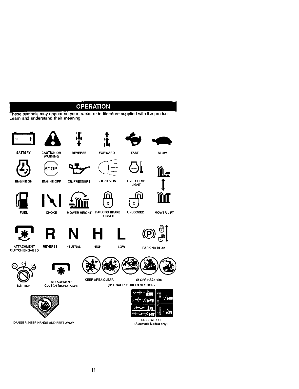
These symbols may appear on your tractor or in literature supplied with the product.
Learn and understand their meaning.
BATrERY CAUTION OR REVERSE FORWARD FAST SLOW
WARNING
ENGINE ON ENGINE OFF OIL PRESSURE LIGHTS ON OVER TEMP
LIGHT
FUEL CHOKE MOWER HEIGHT PARKING BRAKE UNLOCKED
LOCKED
!
MOWERLI_
_r_R N H L
ATrACHMENT REVERSE NEUTRAL HIGH LOW
CLUTCHENGAGED
PARKING BRAKE
®@@@@
_)_ ATTACHMENT KEEP AREA CLEAR SLOPE HAZARDS
IGNITION CLUTCH DISENGAGED (SEE SAFETY RULES SECTION)
DANGER, KEEP HANDS AND FEET AWAY
11
FREE WHEEL
(Automatic Models only)
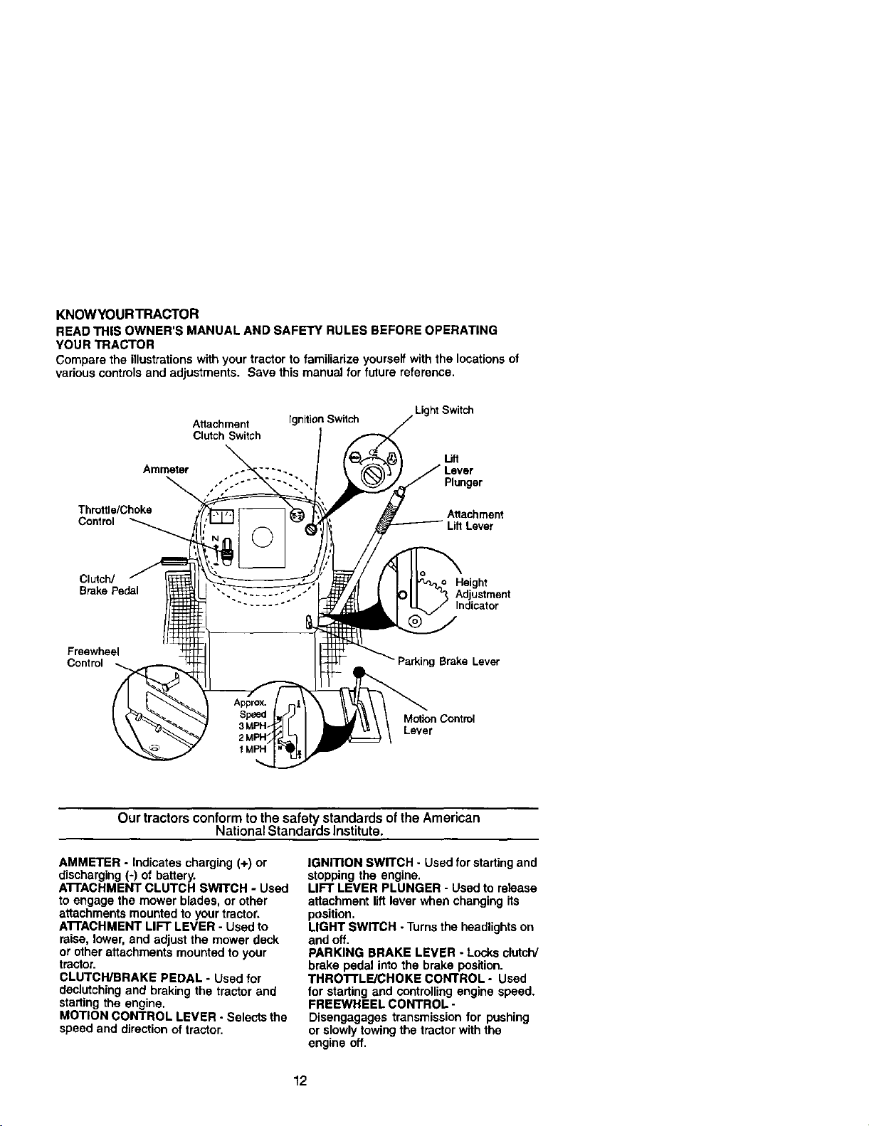
KNOWYOURTRACTOR
READ THIS OWNER'S MANUAL AND SAFETY RULES BEFORE OPERATING
YOUR TRACTOR
Compare the illustrationswith your tractor to familiarize yourself with the locationsof
various controls and adjustments. Save this manual for future reference.
Light Switch
Attachment Ignition Switch
Clutch Switch
Lift
Ammeter
Plunger
Throttle/Choke Attachment
Control Lift Lever
Clutch/ Height
Brake Pedal Adjustment
Indicator
Freewheel
Control Parking Brake Lever
Motion Cootml
Lever
Our tractorsconformto thesafety standards ofthe American
NationalStandards Institute,
AMMETER - Indicates charging (+) or
discharging (-) of battery.
ATFACHMENT CLUTCH SWITCH - Used
to engage the mower blades, or other
attachments mounted to your tractor.
ATFACHMENT LIFT LEVER - Used to
raise, lower, and adjustthe mower deck
or other attachments mounted to your
tractor.
CLUTCWBRAKE PEDAL - Used for
declutching and braking the tractor and
starting the engine,
MOTION CONTROL LEVER - Selects the
speed and direction of tractor,
IGNmON SWITCH - Used for starting and
stopping the engine.
LIFT LEVER PLUNGER - Used to release
attachment liftlever when changing its
position.
LIGHT SWITCH -Turns the headlightson
and off.
PARKING BRAKE LEVER - Locks clutcW
brake pedal into the brake position.
THRO'I'rLE/CHOKE CONTROL - Used
for starting and controllingengine speed.
FREEWHEEL CONTROL -
Disengagages transmission for pushing
or slowlytowingthe tractor with the
engine off,
12
I
HOWTO USEYOURTRACTOR
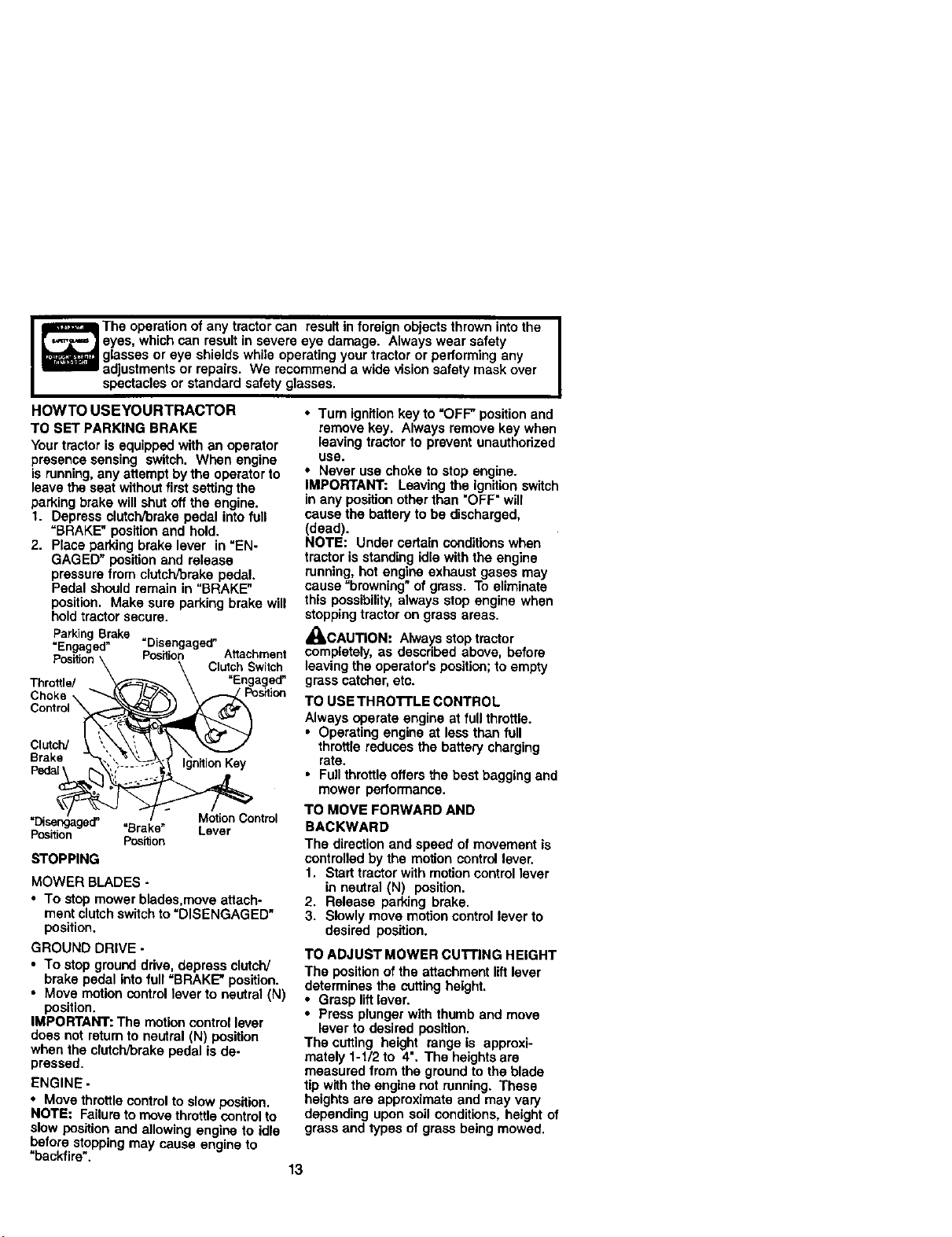
TO SET PARKING BRAKE
Your tractor is equipped with an operator
presence sensing switch. When engine
is running,any attempt by the operatorto
leave the seat withoutfirst setting the
parking brake will shut off the engine.
1. Depress clutch/brake pedal into full
=BRAKE" positionand hold.
2. Place parking brake lever in "EN-
GAGED" position and release
pressure from clutch/brake pedal.
Pedal should remain in "BRAKE"
position. Make sure parking brake will
hold tractorsecure.
ParkingBrake
=Engaged" =Disengaged"
Position Position Attachment
Clutch Switch
Throttle/ "Engaged"
Choke \ Position
Control\
Clutch/
Brake
Motion Control
=Disengaged" "Brake" Lever
Posi_on Position
STOPPING
MOWER BLADES -
• To stop mower blades,move attach-
ment clutchswitchto "DISENGAGED"
position.
GROUND DRIVE -
• To stop groundddve, depress clutch/
brake pedal into full =BRAKE" position.
• Move motioncontrol lever to neutral (N)
position.
IMPORTANT: The motion control lever
does not returnto neutral (N) position
when the clutch/brake pedal is de-
pressed.
ENGINE -
• Move throttlecontrol to slow position.
NOTE: Failureto move throttlecontrol to
slow position and allowing engine to idle
before stopping may cause engine to
"backfire".
The operation of any tractor can result in foreign objects thrown intothe
eyes, which can result in severe eye damage. Always wear safety
glasses or eye shields while operating your tractor or performing any
adjustments or repairs. We recommend a wide vision safety mask over
spectacles or standard safety glasses.
•Tum ignitionkey to =OFF"position and
remove key. Always remove key when
leaving tractor to prevent unauthorized
use.
• Never use choke to stop engine.
IMPOFn'ANT: Leaving the ignitionswitch
in any position other than "OFF" wig
cause the battery to be discharged,
(dead).
NOTE: Under certain conditions when
tractor is standing idle with the engine
running, hot engine exhaust gases may
cause =browning" of grass. To eliminate
this possibility,always stop engine when
stopping tractor on grass areas.
_,CAUTION: Alwaysstop tractor
completely, as described above, before
leavingthe operator's position; to empty
grass catcher,etc.
TO USE THRO'rFLE CONTROL
Always operate engine at full throttle.
• Operating engine at less than full
throttle reduces the battery charging
rate.
• Fullthrottle offers the best bagging and
mower performance.
TO MOVE FORWARD AND
BACKWARD
The direction and speed of movement is
controlled by the motion control lever.
1. Start tractor with motioncontrol lever
in neutral (N) position.
2. Release parking brake.
3. Slowly move motion control lever to
desired position.
TO ADJUST MOWER cu'n'ING HEIGHT
The position of the attachment lift lever
determines the cutting height.
• Grasp liftlever.
• Press plunger with thumb and move
lever to desired position,
The cutting height range is approxi-
mately 1-1/2 to 4". The heights are
measured from the groundto the blade
tip with the engine not running. These
heights are approximate and may vary
depending upon soil conditions, height of
grass and types of grass being mowed,
13
• The average lawn should be cut to
approximately 2-1/2 inches during the
cool season and to over 3 inches
during hot months. For healthier and
better looking lawns, mow often and
after moderate growth.
• For best cutting performance, grass
over 6 inches in height should be
mowed twice. Make the first cut
relatively high; the second to desired
height.
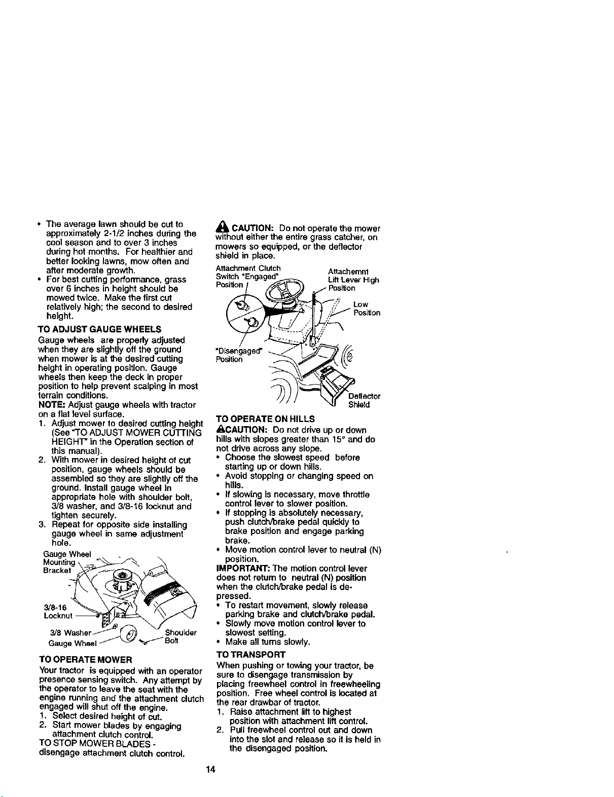
TO ADJUST GAUGE WHEELS
Gauge wheels are properly adjusted
when they are slightlyoff the ground
when mower is at the desired cutting
height in operating position. Gauge
wheels then keep the deck in proper
positionto help prevent scalping in most
terrain conditions.
NOTE: Adjust gauge wheels withtractor
on a flat level surface.
1. Adjust mower to desired cutting height
(See "1"OADJUST MOWER CUl-rlNG
HEIGHT" in the Operation section of
this manual).
2. With mower in desired height of cut
position, gauge wheels should be
assembled so they are slightlyoff the
ground. Install gauge wheel in
appropriate hole with shoulder bolt,
3/8 washer, and 3/8-16 Iocknut and
tighten securely.
3. Repeat for opposite side installing
gauge wheel in same adjustment
hole.
Gauge Wheel
Bracket
3/8-16
3/8 Shoulder
Gauge Wheel _ Bolt
TO OPERATE MOWER
Your tractor is equipped with an operator
presence sensing switch. Any attempt by
the operator to leave the seat with the
engine runningand the attachment clutch
engaged will shut off the engine.
1. Select desired height of cut.
2. Start mower blades by engaging
attachment clutch control.
TO STOP MOWER BLADES -
disengage attachment clutch control.
_k CAUTION: Do not operate the mower
withouteither the entire grass catcher, on
mowers so equipped, or the deflector
shield in place.
AttachmentClutch Attachemnt
Position LiftLeverHigh
=Disengaged"
Position
Shield
TO OPERATE ON HILLS
_CAUTION: Do not drive up or down
hillswith slopes greater than 15° and do
not drive across any slope.
• Choose the slowest speed before
starting up or down hills.
• Avoid stopping or changing speed on
hills.
• If slowing is necessary, move throttle
control lever to slower position.
• If stopping is absolutely necessary,
push clutch/brake pedal quickly to
brake position and engage parking
brake.
• Move motioncontrol lever to neutral (N)
position.
IMPORTANT: The motioncontrol lever
does not return to neutral (N) position
when the clutch/brake pedal is de-
pressed.
• To restart movement, slowly release
parking brake and clutch/brake pedal.
• Slowly move motioncontrol lever to
slowest setting.
• Make all turns slowly.
TO TRANSPORT
When pushing or towing yourtractor,be
sure to disengage transmission by
placing freewheel control in freewheeling
position. Free wheel control is locatedat
the rear drawbar of tractor.
1. Raise attachment liftto highest
position with attachment lift control.
2. Pullfreewheel control out and down
into the slot and release so itis held in
the disengaged position.
14
• Do not push or tow tractor at morethan
two (2) MPH.
• To reengage transmission, reverse
above procedure.
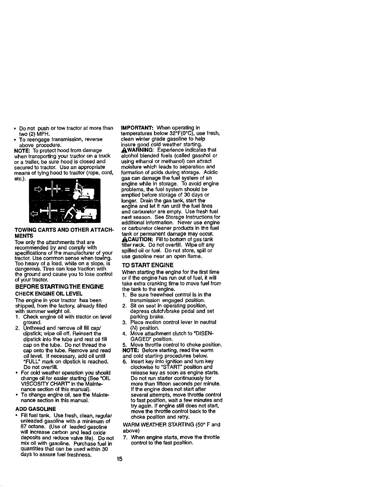
NOTE: To protecthoodfrom damage
when transportingyour tractor on a truck
or a trailer, be sure hood isclosed and
secured totractor. Use an appropriate
means of tying hoodto tractor (rope, cord,
etc.).
TOWING CARTS AND OTHER ATI'ACH-
MENTS
Tow only the attachments that are
recommended by and comply with
specificationsof the manufacturer of your
tractor. Use common sense when towing.
Too heavy of a load, while on a slope, is
dangerous. Tires can lose traction with
the groundand cause you to lose control
ofyour tractor.
BEFORE STARTING THE ENGINE
CHECK ENGINE OIL LEVEL
The engine in your tractor has been
shipped, from the factory, already filled
with summer weight oil.
1. Check engine oil with tractor on level
ground.
2. Unthraad and remove oil fill cap/
dipstick;wipe oil off. Reinsert the
dipstickinto the tube and restoilfill
cap on the tube. Do notthread the
cap onto the tube. Remove and read
oil level. If necessary, add oil until
"FULL" mark on dipstick is reached.
Do not overfill.
• For cold weather operation you should
change oilforeasier starting(See "OIL
VISCOSITY CHART" inthe Mainte-
nance section of this manual).
• To change engine oil, sea the Mainte-
nance section in this manual.
ADD GASOLINE
• Fillfuel tank. Use fresh, clean, regular
unleaded gasoline with a minimum of
87 octane. (Use of leaded gasoline
will increase carbon and lead oxide
depositsand reduce valve life). Do not
mix oil with gasoline. Purchase fuel in
quantities that can be used within 30
claysto assure fuel freshness.
IMPORTANT: When operating in
temperatures below 32°F(O°C), use fresh,
clean winter grade gasoline to help
insure good cold weather starting.
• LWARNING: Experience indicatesthat
alcohol blended fuels (called gasohel or
using ethanol or methanol) san attract
moisture which leads to separation and
formation of acids duringstorage. Acidic
gas can damage the fuel system of an
engine while in storage. To avoid engine
problems, the fuel system should be
emptied before storage of 30 days or
longer. Drain the gas tank, start the
engine and let it ran untilthe fuel lines
and carburetor are empty. Use fresh fuel
next season. See Storage Instructionsfor
additional information. Never use engine
or carburetor cleaner productsin the fuel
tank or permanent damage may occur.
ACAUTION: Fillto bottom ofgas tank
filler neck. Donot overfill. Wipe off any
spilled oil or fuel. Do not store, spillor
use gasoline near an open flame.
TO START ENGINE
When starting the engine forthe firsttime
or if the engine has run out of fuel, it will
take extra cranking time to move fuel from
the tank to the engine.
1. Be sure freewheel control is in the
transmission engaged position.
2. Sit on seat in operating position,
depress clutch/brake pedal and set
parking brake.
3. Place motion control lever in neutral
(N) position.
4. Move attachment clutch to "DISEN-
GAGED" position.
5. Move throftle controlto choke position.
NOTE: Before starting, read the warm
and cold starting procedures below.
6. Insert key intoignitionand turn key
clockwise to "START" position and
release key as soon as engine starts.
Do not run starter continuouslyfor
more than fifteen seconds per minute.
Ifthe engine does notstart after
several attempts, move throttle control
to fast position, wait a few minutesand
try again. If engine stilldoes not start,
move the throttlecontrolback to the
choke positionand retry.
WARM WEATHER STARTING (50° F and
above)
7. When engine starts, move the throttle
controlto the fast position.
15

• The attachments and ground drive can
now be used. Ifthe engine does not
accept the load, restart the engine and
allow it to warm up for one minute
using the choke as described above.
COLD WEATHER STARTING ( 50° F and
below)
7. When engine starts, allow engine to
run with the throttle control in the
choke position until the engine runs
roughly, then move throttlecontrolto
fast position.This may require an
engine warm-up pedod from several
seconds to sevarat minutes, depend-
ing on the temperature.
AUTOMATICTRANSMISSION WARM UP
Before drivingthe unit in cold weather,
the transmissionshould be warmed up as
follows:
1. Be sure the tractor is on level ground.
2. Place the motion control lever in
neutral. Release the parking brake
and let the clutch]brake slowly return
to operating position.
3. Allow one minute for transmission to
warm up. This can be done during
the engine warm up pedod.
• The attachments can also be used
during the engine warm-up period after
the transmissionhas been warmed up.
NOTE: Ifat a high altitude (above 3000
feet) or in cold temperatures (below 32 F)
the carburetor fuel mixture may need to
be adjusted for best engine performance.
See "TO ADJUST CARBURETOR" in the
Service and Adjustments section of this
manual.
PURGETRANSMISSlON
_0ACAUTION: Never engage or disen-
gage freewheel lever while the engine is
running.
To ensure proper operation and perfor-
mance, it is recommended that the
transmission be purged before operating
tractor for the first time. This procedure will
remove any trapped air inside the
transmissionwhich may have developed
during shippingof your tractor.
IMPORTANT: Should your transmission
require removal for service or replace-
ment, it should be purged after rainstalla.
tionbefore operating the tractor.
1. Place tractor safely on level surface
with engine off and parking brake set.
2. Disengage transmission by placing
freewheel control in freewheeling
position (See "TO TRANSPORT" in
this section of manual).
3. Sittingin the tractor seat, start engine.
After the engine is running, move
throttlecontrolto slow position.With
motion control lever in neutral (N)
position, slowly disengage clutch/
brake pedal,
4. Move motion control lever to full
forward position and hold for five (5)
seconds. Move lever to full reverse
position and hold for five (5) seconds.
Repeat this procedure three (3) times.
NOTE: During this procedure there will be
no movement of drive wheels.The air is
being removed from hydraulic drive
system.
5. Move motion control lever to neutral
(N) position. Shut- off engine and set
parking brake.
6. Engage transmission by placing
freewheel control In driving position
(See "TO TRANSPORT" in this section
of manual).
7. Sitting in the tractor seat, start engine.
After the engine is running, move
throttle control to half (1/2) speed. With
motion control lever in neutral (N)
position, slowly disengage clutch/
brake pedal.
8. Slowly move motion control lever
forward, after the tractor moves
approximately five (5) feet, slowly
move motion control lever to reverse
position. After the tractor moves
approximately five (5) feet return the
motion controllever to the neutral (N)
position. Repeat this procedure with
the motioncontrol lever three (3)
6mee.
Your tractor is now purged and now ready
for normal operation.
16
MOWINGTIPS
• Mower should be properly leveled for
best mowing performance. See "TO
LEVEL MOWER HOUSING" in the
Service and Adjustments section of this
manual.
• The left hand side of mower should be
used for trimming.
• Drive so that clippingsare discharged
onto the area that has been cut. Have
the cut area to the fight ofthe tractor.
This will result in a more even distribu-
tion of clippings and more uniform
cutting.
• When mowing large areas, start by
turningto the right so that clippingswill
discharge away from shrubs, fences,
driveways, etc. After one or two
rounds, mow in the opposite direction
making left hand tums untilfinished.
• If grass is extremely tall, it should be
mowed twice to reduce load and
possible fire hazard from dried clip-
pings. Make first cut relativelyhigh; the
second to the desired height.
• Do not mow grass when itis wet. Wet
grass will plug mower and leave
undesirable clumps. Allowgrass to dry
before mowing.
• Always operate engine at full throttle
when mowing to assure better mowing
performance and proper discharge of
material. Regulate ground speed by
selecting a low enough gear to give the
mower cutting performance as well as
the quality ofcut desired.
• When operating attachments, select a
ground speed that willsuit the terrain
and give bestperformance of the
attachment being used.
MULCHING MOWINGTIPS
IMPORTANT: For best performance,
keep mower housing free of built-up
grass and trash. Clean aftereach use.
• The special mulching blade will recut
the grass clippings many times and
reduce them in size so that as they fall
onto the lawn they will disperse intothe
grass and not be noticed. Also, the
mulched grass will biodegrade quickly
to provide nutrientsfor the lawn.
Always mulch with your highestengine
(blade) speed as thiswill provide the
best recutting action ofthe blades.
• Avoid cuttingyour lawn when it is wet.
Wet grass tends to form clumps and
interferes with the mulching action.
The best time to mow your lawn isthe
early afternoon. At this time the grass
has dded and the newly cut area will
not be exposed to the direct sun.
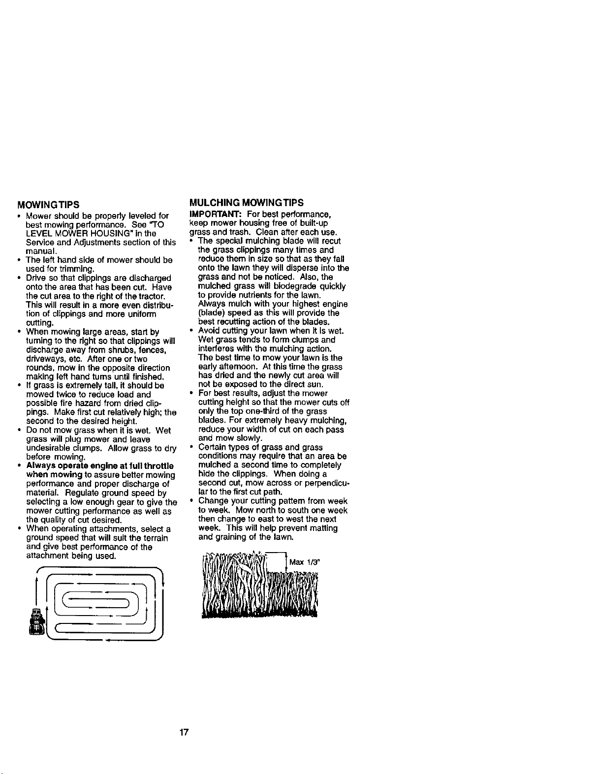
• For best results,adjustthe mower
cuttingheight so that the mower cuts off
onlythe top one-third of the grass
blades. For extremely heavy mulching,
reduce your width of cut on each pass
and mow slowly.
• Certain types of grass and grass
conditionsmay require that an area be
mulched a second time to completely
hide the clippings. When doing a
second cut, mow across or perpendicu-
lar to the first cut path.
• Change your cutting pattern from week
to week. Mow northto south one week
then change to east to west the next
week. This will help prevent matting
and graining of the lawn.
' Max 1/3"
17
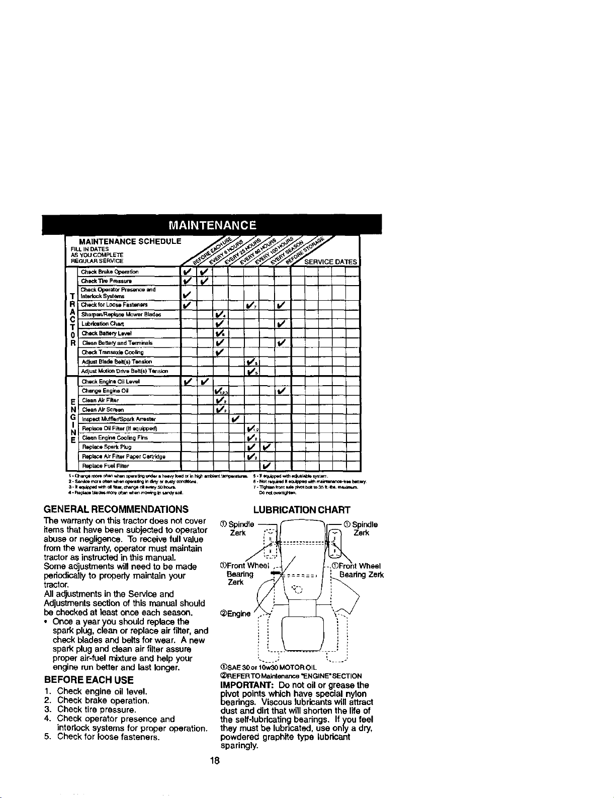
MAINTENANCE SCHEDULE
FILLINDATES
ASYOUCOMPLEI_
REGULARSERVICE
ChDck Brake Operatic_
Clted_Tim pr_ssu_ 11/ i_
Clled_ Operator PrESence and
InterlookSysten_ f_
Sharpo_RepjuceMowerBlad_ I/4
Ch_ Battery L_wl
Clean Battery and Temlk_als _1 I
Check Tmnssxle Cooling 11_
AdjustBledeBait(s)Tendon I_#s
Adjust Mot_ Orivo Belt(s) Tension pi_/5
CheckEngineoilLo_el _1 i I_
Cllange Engie_ Oil I_1,_
Clean Air Filtar _#l
Clean Air Scr_on 11_1_
InSpectMufflerfSpatk Armstlr _/
Replace OUFilter (if equipped) J_
Clean Engine Cooling Fins I//_
Replace/dr Fi_er Paper cartridge _/_ I
P,_olace Fuel Filter V I
GENERAL RECOMMENDATIONS
The warranty onthistractordoes not cover
items that have been subjected to operator
abuse or negligence, To receive full value
fromthe warranty,operatormust maintain
tractoras instructedin this manual.
Some adjustments will need to be made
periodically to properly maintain your
tractor.
All adjustments in the Service and
Adjustments section of this manual should
be checked at least once each season,
• Once a year you should replace the
spark plug, clean or replace air filter, and
check blades and belts for weer. A new
spark plug and clean air filter assure
proper air-fuel mixture and help your
engine run better and last longer,
BEFORE EACH USE
1, Check engine oil level.
2. Check brake operation,
3. Check tire pressure,
4. Check operator presence and
interlock systems for proper operation.
5. Check for loose fasteners.
LUBRICATION CHART
Spindle - (_Spindle
Zerk Zerk
_Front Wheel
Bearing Beadng Zerk
Zerk
(_SAE 30 o_10w30 MOTOR OIL
(_REFERTO Ma_rdenance _ENGINE" SECTION
IMPORTANT: Do not oil or grease the
pivot points which have special nylon
beadngs. Viscous lubricants will attract
dust and dirt that willshorten the life of
the self-lubricatingbearings. If you feel
they must be lubricated, use only a dry,
powdered graphite type lubricant
sparingly.
18
rRACTOR
_.lwaysobserve safety rules when
)erforming any maintenance,
5RAKE OPERATION
_ftractor requires more than six (6) feet
_topping distance at high speed in
_ighest gear, then brake must be ad-
iusted. (See "TO ADJUST BRAKE"in the
Service and Adjustmentssection of this
manual).
TIRES
• Maintain proper air pressure in all tires
(See =PRODUCT SPECIFICATIONS"
section of this manual).
• Keep tires free of gasoline, oil, or insect
control chemicals whichcan harm
rubber.
• Avoid stumps, stones, deep ruts, sharp
objects and other hazards that may
cause tire damage.
NOTE: To seal tire puncturesand prevent
flat tires due to slow leaks, tire sealant
may be purchasedfrom your local parts
dealer. Tire sealant also preventstire dry
rot and corrosion.
OPERATOR PRESENCE SYSTEM
Be sure operator presence and interlock
systems are workingproperly. If your
tractor does not functionas described,
repair the problem immediately.
• The engine should not start unless the
brake pedal is fully depressed and
attachement clutchcontrol is in the
disengaged position.
• When the engine is running, any
attempt by the operator to leave the
seat without first setting the parking
brake should shut off the engine.
• When the engine is running and the
attachment clutchis engaged, any
attempt by the operator ta leave the
seat shouldshut off the engine.
• The attachment clutch should never
operate unless the operator is in the
seat.
BLADE CARE
For best results mower blades must be
kept sharp. Replace bent or damaged
blades.
BLADE REMOVAL
1. Raise mower to highest positionto
allow access to blades.
2. Remove hex bolt, lock washer and flat
washer secudng blade.
3. Install new or resharpened blade with
trailing edge up towards deck as
shown.
19
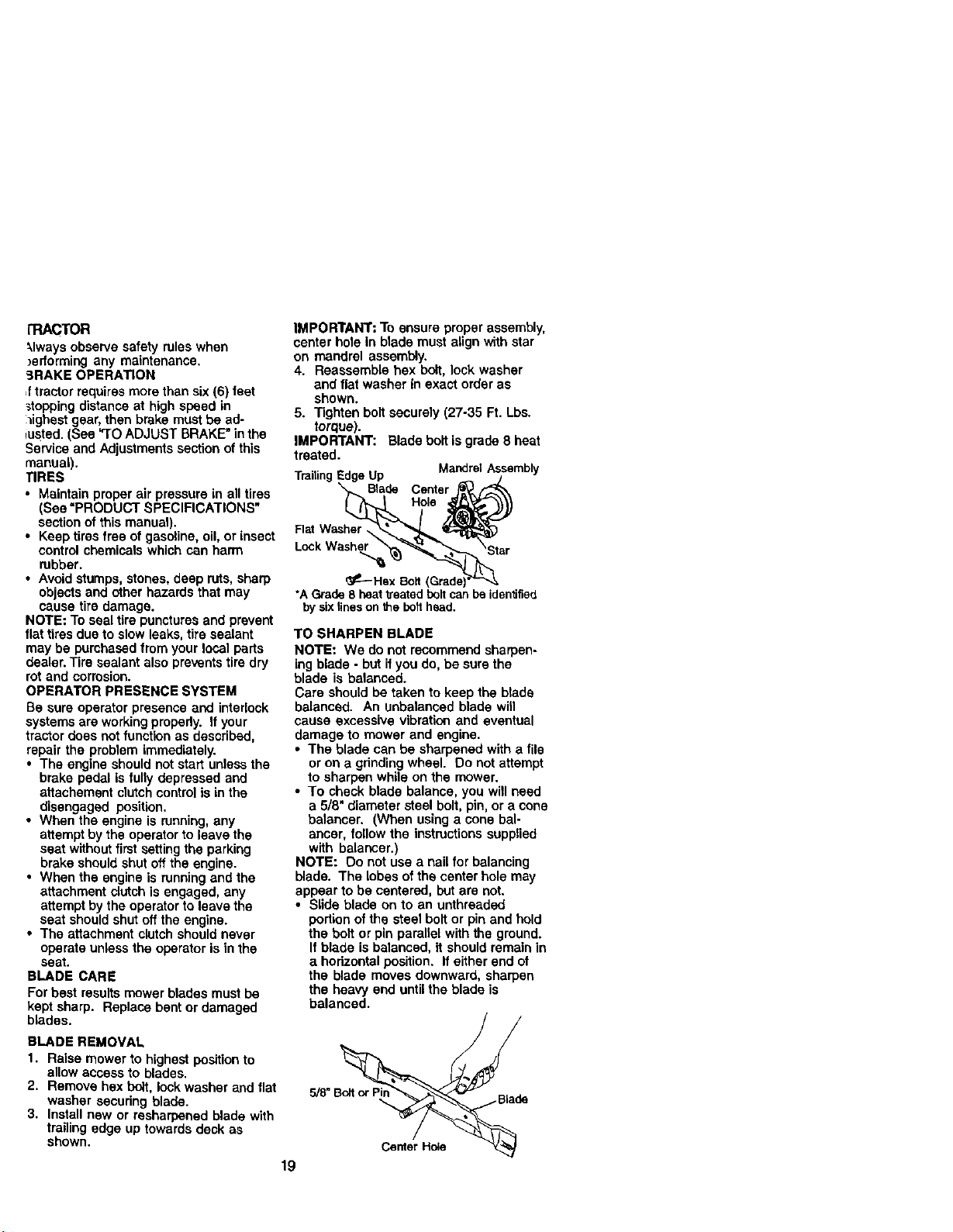
IMPORTANT: To ensure proper assembly,
center hole In blade must align with star
on mandrel assembly.
4. Reassemble hax bolt, lock washer
and flat washer in exact order as
shown.
5. Tighten boltsecurely (27-35 Ft. Lbs.
torque).
IMPORTANT: Blade bolt isgrade 8 heat
treated.
MandrelAssembly
TrailingEdgeUp /
X,_ Blade Center j_ ,_
FlatWasher __
_---Hex Bolt(Grade)_"_.
*AGrade8 heattreatedboltcanbe identified
bysixlinesonthebolthead.
TO SHARPEN BLADE
NOTE: We do not recommend sharpen-
ing blade - but ifyou do, be sure the
blade is balanced.
Care should be taken to keep the blade
balanced. An unbalanced blade will
cause excessive vibration and eventual
damage to mower and engine.
• The blade can be sharpened with a file
or on a grindingwheel. Do not attempt
to sharpen while on the mower.
• To check blade balance, you will need
a 5/8" diameter steel bolt, pin, or a cone
balancer. (When using a cone bal-
anoer, follow the instructionssupplied
with balanoer.)
NOTE: Do not use a nail for balancing
blade. The lobes ofthe center hole may
appear to be centered, but are not.
• Slide blade on to an unthraaded
portion ofthe steel boltor pin and hold
the bolt or pin parallel with the ground.
If blade is balanced, it should remain in
a horizontal position. If either end of
the blade moves downward, sharpen
the heavy end untilthe blade is
balanced.
Ce_erH_e

BA'rrERY
Yourtractor has a battery charging system
which is sufficientfor normal use. How-
ever,periodic charging ofthe battery with
an automotive charger will extend its life.
• Keep battery and terminals clean.
• Keep battery bolts tight.
• Keep smallvent holes open.
• Recharge at 6-10 amperes for 1 hour.
NOTE: The originalequipment battery on
your tractor is maintenance free. Do not
attemptto open or remove caps or covers.
Addingor checking level of electrolyte is
not necessary.
TO CLEAN BA'I-rERY AND TERMINALS
Corrosionand dirt onthe battery and
terminals can cause the batteryto "leak"
power.
1. Open battery box door.
2. Disconnect BLACK battery cable first
then RED battery cable and remove
batteryfrom tractor.
3. Rinse the battery with plain water and
dry.
4. Clean terminals and battery cable
ends with wire brush until bright.
5. Coat terminals with grease or petro-
leum jelly.
6. Reinstall battery (See "REPLACING
BAI-rERY" in the SERVICE AND
ADJUSTMENTS section of this
manual).
V-BELTS
Check V-beltsfor deterioration and wear
after 100 hours of operation and replace
if nocescary. The belts are not adjustable.
Replace belts if they begin to slip from
wear,
TRANSAXLE COOLING
The transmissionfan and cooling fins
should be kept clean to assure proper
cooling.
Do not attempt toclean fan or transmis-
sion while engine is running or while the
transmissionis hot.To prevent possible
damage to seals, do not use high
pressure water or steam to clean
transaxle.
• Inspect coolingfan to be sure fan
blades are intactand clean.
• Inspect coolingfins for dirt, grass
clippingsand other materials. To
prevent damage to seals, do not use
compressed air or high pressure
sprayer to clean cooling fins.
TRANSAXLE PUMP FLUID
The transaxle was sealed at the factory
and fluid maintenance is not required for
the lifeof the transaxte. Should the
transaxle ever leak or require servicing,
contact your nearest authorized service
center/department.
ENGINE
LUBRICATION
Only use high quality detergent oil rated
with API service classificationSF-SJ,
Select the oil'sSAE viscosity grade
according to your expected operating
temperature.
Change the oil after every 50 hours of
operation or at least once a year if the
tractor is not used for 50 hours in one
year,
Check the crankcase oil level before
starting the engine and after each eight
(8) hours of operation. Tighten oiltill cap/
dipstick securelyeach time you check the
oil level.
TO CHANGE ENGINE OIL
Determine temperature range expected
before oil change. All oil must meet API
service classificationSF-SJ,
• Be sure tractor is on level surface.
• Oil will drain more freely when warm,
• Catch oil in a suitable container.
1. Remove oil fill cap/dipstick. Be careful
notto allow dirt to enter the engine
when changing oil.
2. Remove cap from end of drainvalve
and install the drain tube onto the
f_ing.
3. Unlock drain valve by pushing inward
slightly and turning counterclockwise.
4. To open, pull out on the drain valve.
5. After oilhas drained completely, close
and lock the drain valve by pushing
inward and tuming clockwise until the
pin is in the locked position as shown.
6. Remove the drain tube and replace
the cap onto to the end of the drain
valve.
7. Refill engine with oil through oil fill
dipstick tube. Pour slowly. Do not
overfill. For approximate capacity see
"PRODUC3" SPECIFICATIONS"
section of this manual.
2O
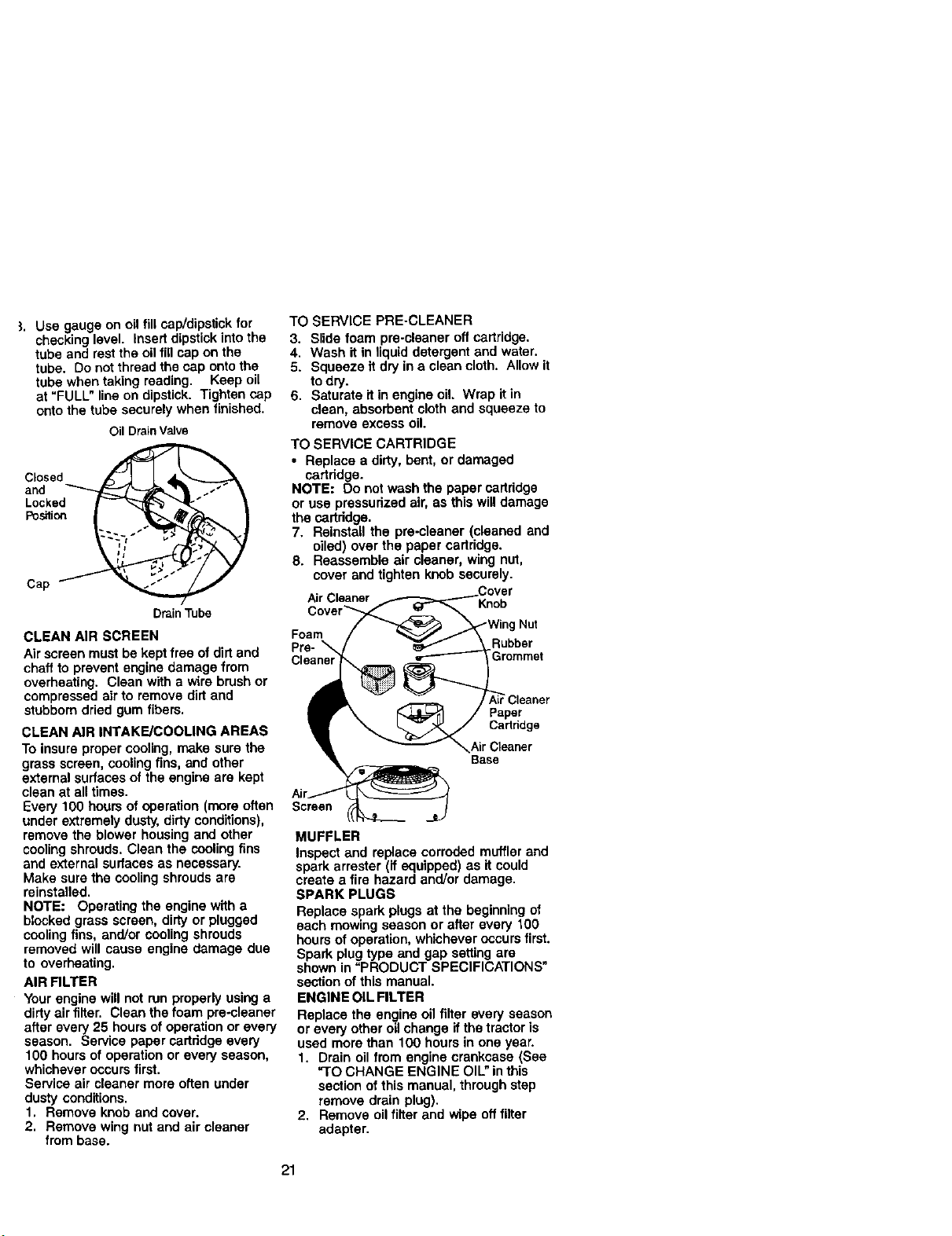
]. Use gauge on oil fill cap/dipstick for
checking level. Insert dipstick into the
tube and rest the oil fill cap on the
tube. Do not thread the cap onto the
tube when taking reading. Keep oil
at "FULL" line on dipstick. Tighten cap
onto the tube securely when finished.
OilDrainValve
CLosed_ _1
PoNion_
Cap
Drain Tube
CLEAN AIR SCREEN
Air screen must be kept free of dirt and
chaff to prevent engine damage from
overheating. Clean with a wire brush or
compressed air to remove dirtand
stubborn dried gum fibers.
CLEAN AIR INTAKE/COOLING AREAS
To insure proper cooling, make sure the
grass screen, cooling fins, and other
external surfaces of the engine are kept
clean at all times.
Every 100 hours of operation (mare often
under extremely dusty, dirty conditions),
remove the blower housing and other
coolingshrouds. Clean the cooling fins
and external surfaces as necessary.
Make sure the cooling shrouds are
reinstalled.
NOTE: Operating the engine with a
blocked grass screen, dirty or plugged
coolingfins, and/or cooling shrouds
removed will cause engine damage due
to overheating.
AIR FILTER
Your engine will not run properly using a
dirty air filter. Clean the foam pre-cleaner
after every 25 hours of operation or every
season. Service paper cartridge every
100 hours of operation or every season,
whichever occurs first.
Service air cleaner more offeR under
dusty conditions.
1. Remove knob and cover.
2. Remove wing nut and air cleaner
from base.
TO SERVICE PRE-CLEANER
3. Slide foam pre.cleaner off cartridge.
4. Wash it in liquid detergent and water.
5. Squeeze it dry in a clean cloth. Allow it
to dry.
6. Saturate it in engine oil. Wrap it in
clean, absorbent cloth and squeeze to
remove excess oil.
TO SERVICE CARTRIDGE
• Replace a dirty, bent, or damaged
cartddge.
NOTE: Do not wash the paper cartridge
or use pressurized air, as this willdamage
the cartddge.
7. Reinstall the pre-cleaner (cleaned and
oiled) over the paper cartddge.
8. Reassemble air cleaner, wing nut,
cover and tighten knob securely.
Air Cleaner Knob
Foam
Pra-
Cleaner
| Nut
Rubber
_Cleaner
Paper
Cadddge
Air Cleaner
Base
Sc_en
MUFFLER
Inspect and replace corroded muffler and
spark arrester (ff equipped) as it could
create a fire hazard and/or damage.
SPARK PLUGS
Replace spark plugs at the beginning of
each mowing season or after every 100
hours of operation, whichever occurs first.
Spark plugtype and gap setting are
shown in "PRODUCT SPECIFICATIONS"
section of this manual.
ENGINE OIL FILTER
Replace the engine oil filter every season
or every other oil change ifthe tractor is
used more than 100 hours in one year.
1. Drain oil from engine crankcase (See
"TO CHANGE ENGINE OIL" inthis
section of this manual, through step
remove drain plug).
2. Remove oil filter and wipe offfilter
adapter.
21
3. Apply a thin coating of new engine oil
to the rubber gasket on replacement
oil filter.
4. Install replacement oil filter on filter
adapter. Turn oil filter clockwise until
rubber gasket contacts the filter
adapter, then tighten filter an addi-
tional 1/2 turn.
5. Fill crankcase with new oil (See "TO
CHANGE ENGINE OIL" in this section
of this manual). For approximate
capacity see "PRODUCT SPECIFICA-
TIONS" section of this manual.
6. Start the engine and check for oil
leaks. Correct any leaks before
placing engine into full operation.
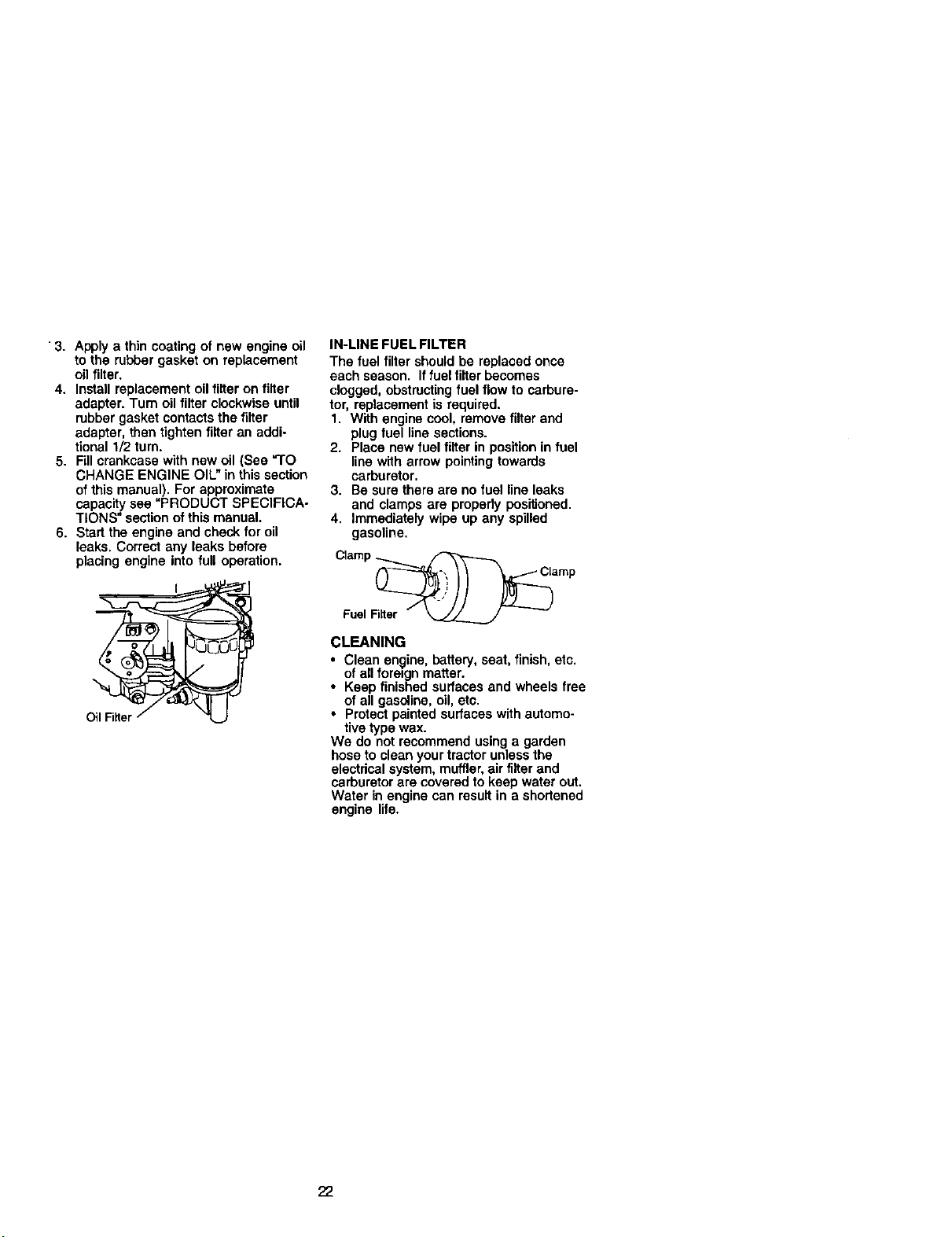
IN-LINE FUEL FILTER
The fuel filter should be replaced once
each season. Iffuel filter becomes
clogged, obstructingfuel flow to carbure-
tor, replacement is required.
1. With engine cool, remove filter and
plug fuel line sections.
2. Place new fuel filter in positionin fuel
line with arrow pointingtowards
carburetor.
3. Be sure there are no fuel line leaks
and clamps are propedy positioned.
4. Immediately wipe up any spilled
gasoline.
Clamp _ .
FuelNiter _ --
CLEANING
• Clean engine, battery, seat, finish,etc.
of all foreign matter.
• Keep finished surfaces and wheels free
of all gasoline, oil, etc.
• Protect painted surfaces with automo-
tive type wax.
We do not recommend using a garden
hose to clean your tractor unless the
electrical system, muffler,air filter and
carburetor are covered to keep water out,
Water in engine can result in a shortened
engine life.
22
_CAUTION: BEFORE PERFORMING ANY SERVICE OR ADJUSTMENTS:
1. Depress clutch/brake pedal fullyand set parking brake.
2. Place motion control lever in neutral (N) position.
3. Place attachment clutch in "DISENGAGED" position.
4. Turn ignitionkey "OFF" and remove key.
5. Make sure the blades and all moving parts have completely stopped.
6. Disconnect spark plug wire from spark plug and place wire where it cannot
come in contact with plug.
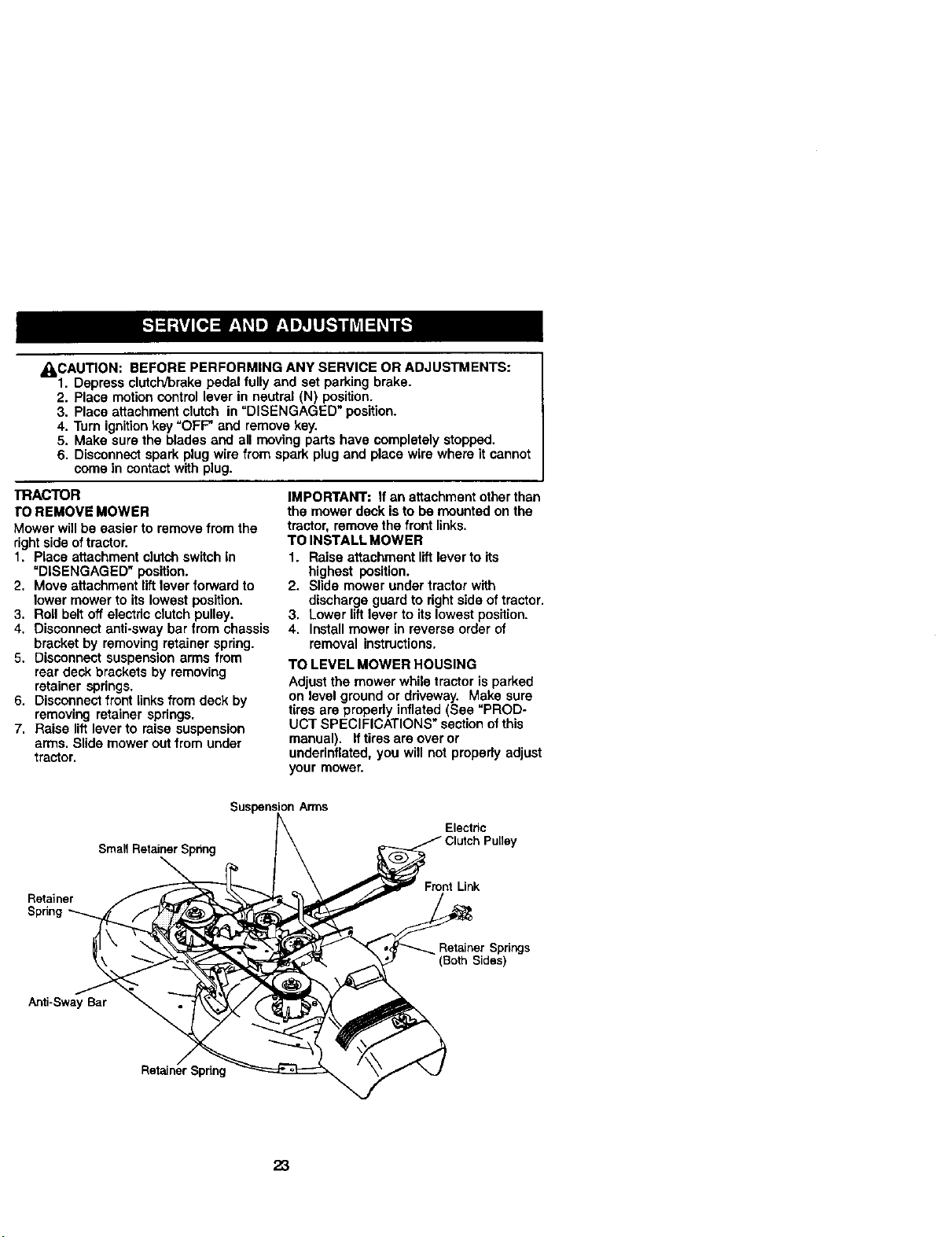
TRACTOR
ro REMOVE MOWER
Mower will be easier to remove from the
right side oftractor.
1. Place attachment clutchswitch in
"DISENGAGED" position.
2. Move attachment lift lever forward to
lower mower to its lowest position.
3. Roll belt off electric clutch pulley.
4. Disconnect anti-sway bar from chassis
bracket by removing retainer spring.
5. Disconnect suspension arms from
rear deck brackets by removing
retainer springs.
6. Disconnect front links from deck by
removing retainer springs.
7. Raise lift lever to raise suspension
arms. Slide mower out from under
tractor.
IMPORTANT: if an attachment other than
the mower deck isto be mounted on the
tractor, remove the front links.
TO INSTALL MOWER
1. Raise attachment littlever to its
highest position.
2. Slide mower under tractor with
discharge guard to rightside of tractor.
3. Lower lift lever to its lowest position.
4. Install mower in reverse order of
removal instructions.
TO LEVEL MOWER HOUSING
Adjust the mower while tractor is parked
on level ground or driveway. Make sure
tires are properly inflated (See "PROD-
UCT SPECIFICATIONS" sectionofthis
manual). If tires are over or
underinflated, you will not properly adjust
your mower.
Suspension Arms
Small Retainer Spnng
Electdc
R_ainer
Spnng
Link
Retainer Springs
(Both Sides)
Anti-Sway Bar
Retainer Spdng
23
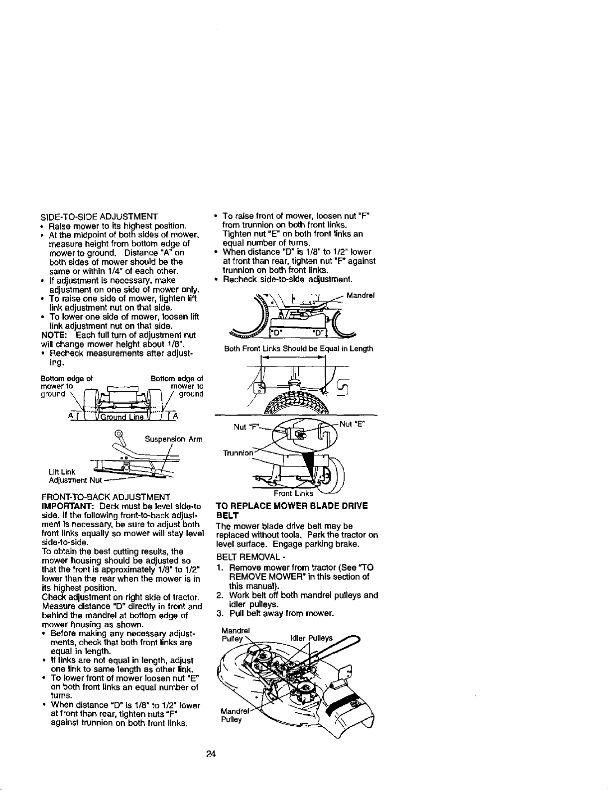
SIDE-TO-SIDE ADJUSTMENT
• Raise mower to its highest position.
• At the midpointof both sides of mower,
measure height from bottom edge of
mower to ground. Distance"A" on
both sides of mower should be the
same or within 1/4" of each other.
• Ifadjustment is necessary, make
adjustment on one side of mower only.
• To raise one side of mower, tighten lift
link adjustment nut on that side.
• To lower one side of mower, loosen lift
link adjustment nut on that side.
NOTE: Each full turn of adjustment nut
will change mower height about 1/8".
• Recheck measurements after adjust-
ing.
Bottomedgeof Bottomedgeof
Lift Link _on
Arm
Adjustment Nut
FRONT-TO-BACK ADJUSTMENT
IMPORTANT: Deck must be level side-to
side. Ifthe followingfront-to-beck adjust-
ment is necessary, be sure to adjustboth
front links equally so mower will stay level
side-to-side.
To obtainthe best cutting results, the
mower housing should be adjusted so
that the front is approximately 1/8"to I/2"
lower than the rear when the mower is in
its highest position.
Check adjustment on rightside oftractor,
Measure distance "D" directly in front and
behind the mandrel at bottom edge of
mower housing as shown.
• Before making any necessary adjust-
ments, check that both front links are
equal in length.
• If links are not equal in length, adjust
one link to same length as other link.
• To lower front of mower loosen nut "E"
on both front links an equal number of
turns.
• When distance =D" is 1/8" to 1/2" lower
at front than rear, tighten nuts "P
against trunnion on both front links.
• To raise front of mower, loosen nut "F"
from trunnion an both front links.
Tighten nut "E" on both front links an
equal number of turns.
• When distance "D" is 1/8" to 1/2" lower
at front than rear, tighten nut "F" against
trunnion on both front links.
• Recheck side-to-side adjustment.
__1_[ • o _. Mandrel
BothFrontUnks Shouldbe EqualinLength
Nut =_
Tmnnion_
Front Links
TO REPLACE MOWER BLADE DRIVE
BELT
The mower blade drive belt may be
replaced withouttools. Park the tractor on
level surface. Engage parking brake.
BELT REMOVAL -
1. Remove mower from tractor(See "TO
REMOVE MOWER" in this sectionof
this manual).
2. Work belt off both mandrel pulleys and
idler pulleys.
3. Pull belt away from mower.
Mandrel
Pulle
PuUey
24
}ELT INSTALLATION -
L Install new belt in reverse order of
removal.
_. Make sure belt is in all pulley grooves
and inside all belt guides.
3. Install mower in reverse order of
removal instructions.
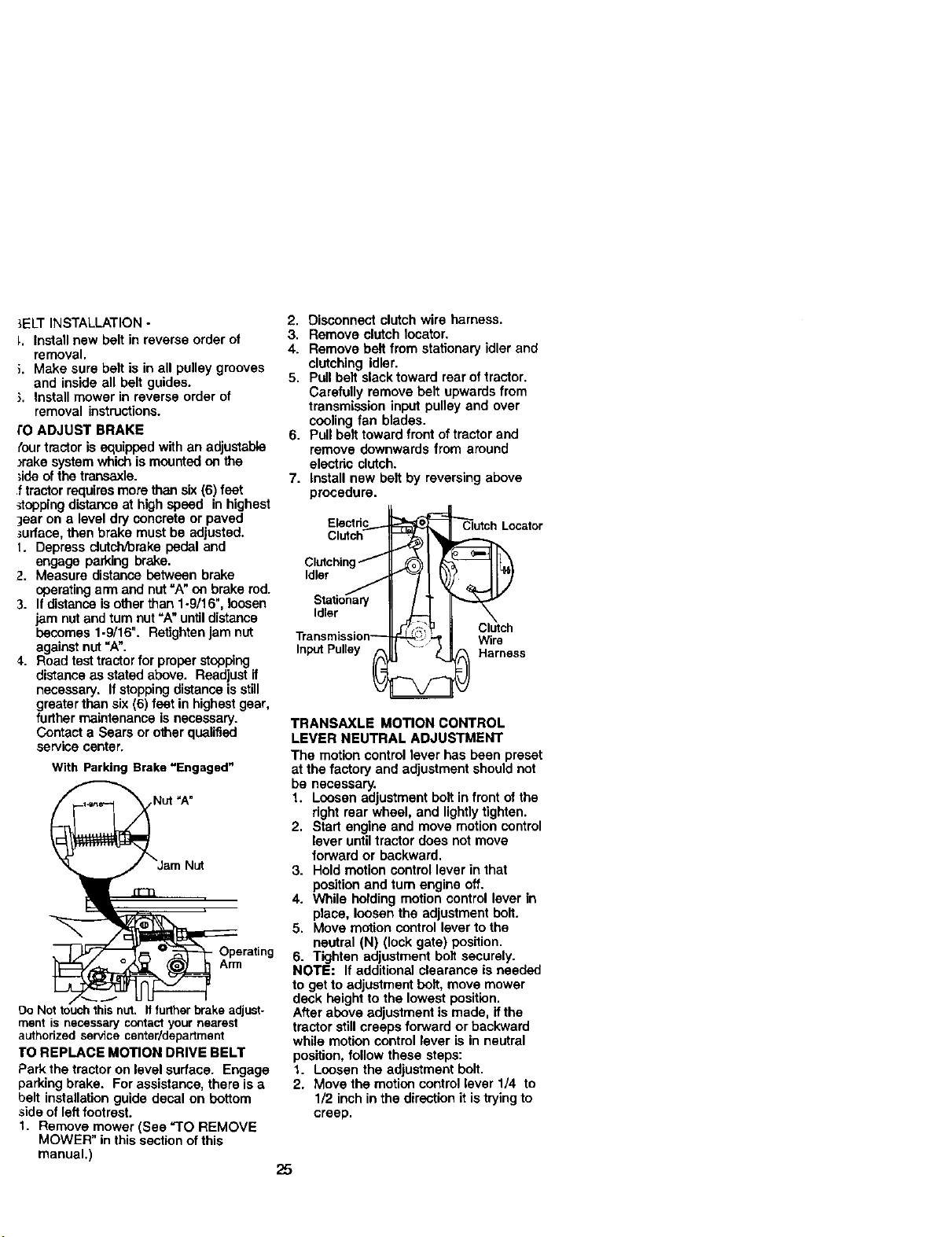
I'0 ADJUST BRAKE
{ourtractoris equippedwith an adjustable
)rake systemwhich is mountedon the
;ide ofthe transaxle.
f tractorrequiresmore than six(6) feet
_opping distanceat high speed in highest
joor on a level dry concrete or paved
_urface, then brake must be adjusted.
1. Depress clutch_rake pedal and
engage parking brake.
2. Measure distance between brake
operatingarm and nut=A"an brake rod.
3. Ifdistance isotherthan 1-9/16", loosen
jam nutand turnnut =A"untildistance
becomes 1-9/16". Refightenjam nut
againstnut"A".
4. Road test tractor for proper stopping
distanceas stated above. Readjust if
necessary, Ifstoppingdistance isstill
greaterthan six (6) foot in highest gear,
furthermaintenance is necessary.
Contact a Sears or other qualified
servicecenter.
With Parking Brake"Engaged"
Operating
Arm
Do Not touchthisnut. Itfurtherbrakeadjust-
ment is necessary contactyour nearest
authorizedservicecenter/department
I'O REPLACE MOTION DRIVE BELT
Park the tractor on level surface. Engage
parking brake. For assistance, there is a
belt installation guide decal on bottom
side of leftfootrest.
t. Remove mower (See =TO REMOVE
MOWER" in this section ofthis
manual,)
2. Disconnect clutch wire harness.
3. Remove clutch locator.
4. Remove belt from stationary idler and
clutching idler.
5. Pull belt slack toward rear of tractor.
Carefully remove belt upwards from
transmission input pulley and over
cooling fan blades.
6. Pull belt toward front of tractor and
remove downwards from around
electdc clutch.
7. Install new belt by reversing above
procedure.
Electdc_
c, °h
Clutchingf I.._
Idler J
Idler
h-..
_J " Clutch
_L._; Wire
InputPulley Harness
TRANSAXLE MOTION CONTROL
LEVER NEUTRAL ADJUSTMENT
The motion control lever has been preset
at the factory and adjustment should not
be necessary.
1. Loosen adjustment bolt in front of the
dght rear wheel, and lightlytighten.
2. Start engine and move motioncontrol
lever untiltractor does not move
forward or backward,
3. Hold motion control lever in that
position and rum engine off.
4. While holding motion control lever in
place, loosen the adjustment bolt.
5. Move motion control lever to the
neutral (N) (lock gate) position.
6. Tighten adjustment bolt securely.
NOTE: If additional clearance is needed
to get to adjustment bolt, move mower
deck height to the lowest position.
After above adjustment is made, if the
tractor stillcreeps forward or backward
while motioncontrol lever is in neutral
position, follow these steps:
1. Loosen the adjustment bolt.
2. Move the motion control lever 1/4 to
1/2 inchin the directionit istryingto
creep.
25
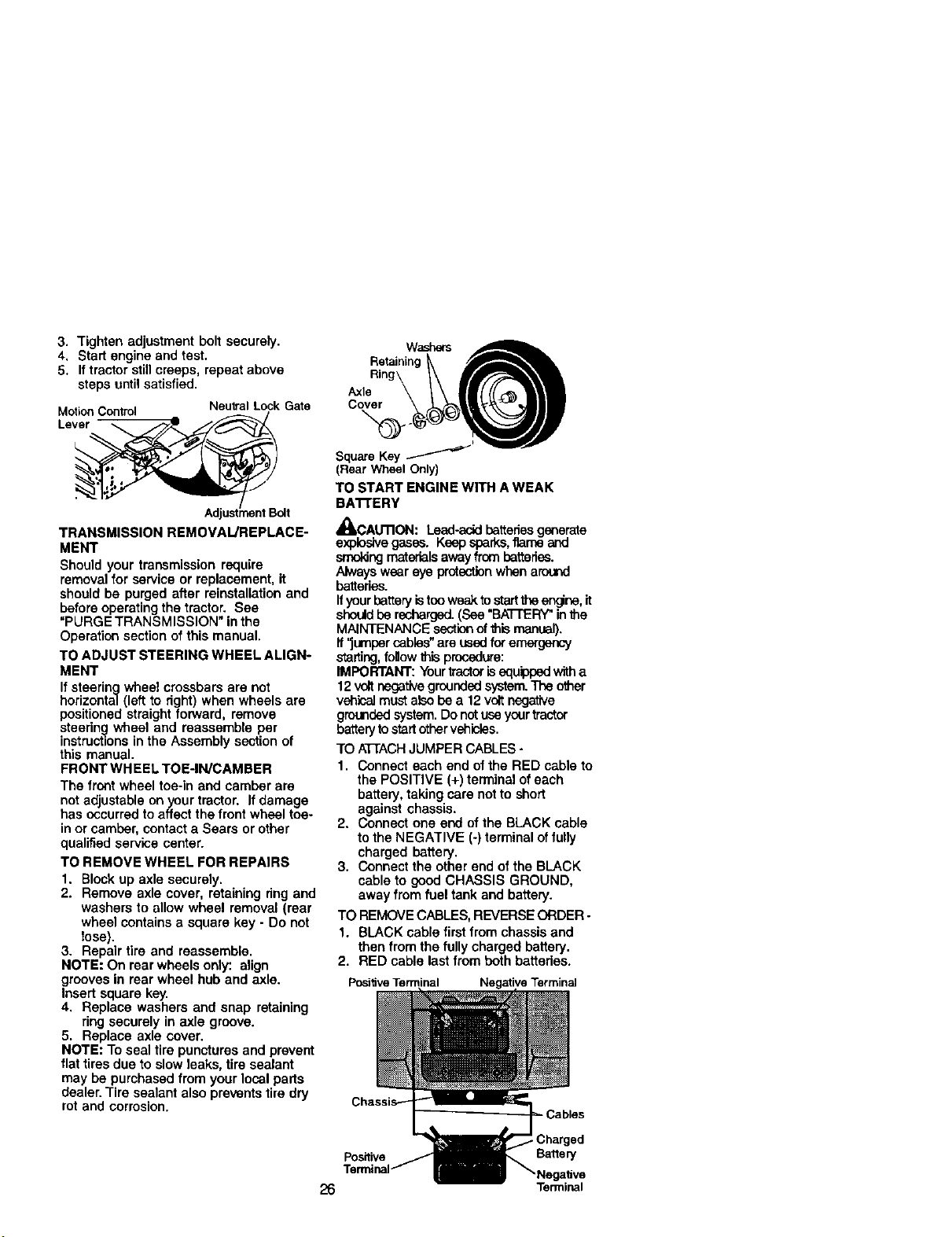
3. Tighten adjustment bolt securely.
4. Start engine and test.
5. If tractor still creeps, repeat above
steps until satisfied.
MotionControl NeutralLock Gate
TRANSMISSION REMOVAL/REPLACE-
MENT
Should your transmission require
removalfor service or replacement, it
should be purged after reinstallationand
beforeoperating the tractor. See
"PURGE TRANSMISSION" in the
Operation section of this manual.
TO ADJUST STEERING WHEEL ALIGN-
MENT
If steering wheel crossbars are not
horizontal (left to right) when wheels are
positioned straight forward, remove
steering wheel and reassemble per
instructlons in the Assembly section of
this manual.
FRONT WHEEL TOE-IN/CAMBER
The front wheel toe-in and camber are
notadjustable on your tractor. If damage
has occurredto affect the front wheel toe-
in or camber, contacta Sears or other
qualified service center.
TO REMOVE WHEEL FOR REPAIRS
1. Blockup axle securely.
2. Remove axle cover, retaining ring and
washers to allow wheel removal (rear
wheel containsa square key - Do not
lose).
3. Repair tire and reassemble.
NOTE: On rear wheels only: align
grooves in rear wheel hub and axle.
Insert square key.
4. Replace washers and snap retaining
ring securely in axle groove.
5. Replace axle cover.
NOTE: Toseal tire punctures and prevent
flat tires due to slow leaks, tire sealant
may be purchased from your local parts
dealer. Tire sealant also prevents tire dry
rot and corrosion.
Retaining
Ring
Axle
Square Key
(RearWheelOnly)
TO START ENGINE WITH A WEAK
BA'rFERY
_IILcAUTION: Lead-acidbatteriesgsnerate
explosivegases. Keep sparks,flame and
_ng materialsawayfrom batteries.
Always wear eye protectionwhenaround
batteries.
Ifyour batteryistooweak tostartthe engine, it
should be recharged. (See "BATTERY"in the
MAINTENANCE section of this manual).
If"jumper cables" are used for emergency
staffing, follow this procedure:
IMPORTANT: Yourtractor is equippedwith a
12 voltnegativegrounded system.The other
vehicalmust also be a 12voltnegative
grounded system. Do not use your tractor
batterytostart other vehicles.
TO ATTACHJUMPER CABLES -
1. Connect each end of the RED cable to
the POSITIVE (+) terminal of each
battery, taking care not to short
against chassis.
2. Connect one end ofthe BLACK cable
to the NEGATIVE (-) terminal of fully
charged battery.
3. Connect the other end of the BLACK
cable to good CHASSIS GROUND,
away from fuel tank and battery.
TO REMOVECABLES, REVERSE ORDER -
1. BLACK cable first from chassis and
then from the fully charged battery.
2. RED cable last from both batteries.
Posi_ve Terminal Negative Terminal
Positive Battery
26 Terminal
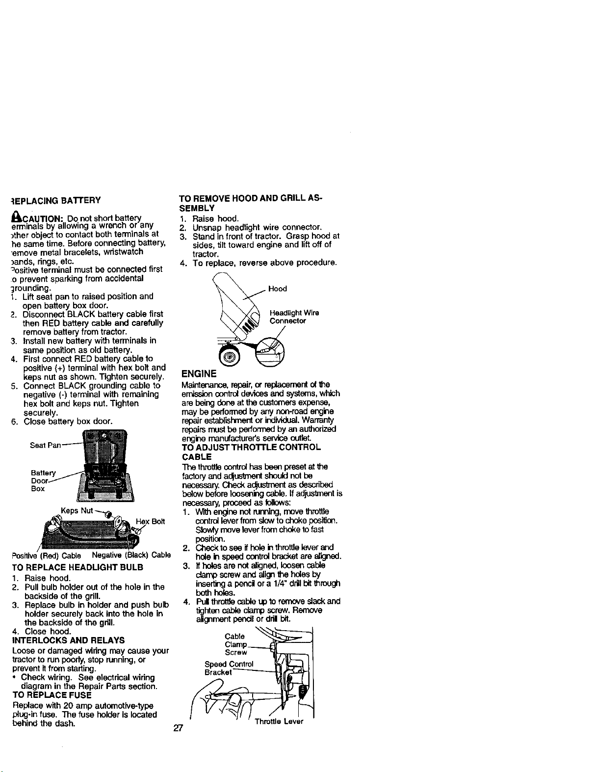
-_EPLACING BAI-FERY
_CAUT ON: Do notshort battery
erminals by allowing a wrench or any
)thor object to contact both terminals at
he same time. Before connectingbattery,
emove metal bracelets, wristwatch
)ands, rings, etc.
=ositive terminal must be connected first
:o prevent sparking from accidental
;rounding.
1. Liftseat pan to raised position and
open battery box door.
2. Disconnect BLACK battery cable first
then RED battery cable and carefully
remove batteryfrom tractor.
3. Install new battery with terminals in
same positionas old battery.
4. First connectRED battery sable to
positive(+) terminal with hex bolt and
keps nut as shown.Tighten securely.
5. Connect BLACK grounding cable to
negative (-) terminal with remaining
hex bolt and keps nut.Tighten
securely.
6. Close battery box door.
Seat
Box
xBolt
Positive(Red)Cable Negative(Black)Cable
TO REPLACE HEADLIGHT BULB
1. Raise hood.
2. Pull bulb holder out of the hole in the
backside of the grill.
3. Replace bulb in holder and push bulb
holder securely back intothe hole in
the backside of the grill,
4. Close hood.
INTERLOCKS AND RELAYS
Loose or damaged widng may cause your
tractorto run poorly,stop running,or
prevent itfrom starting.
• Check wiring. See electrical wiring
diagram in the Repair Parts section.
TO REPLACE FUSE
Replace with 20 amp automotive-typa
plug-in fuse. The fuse holderis located
behind the dash.
TO REMOVE HOOD AND GRILL AS-
SEMBLY
1. Raise hood.
2. Unsnap headlight wire connector.
3. Stand in front of tractor. Grasp hood at
sides, tilttoward engine and liftoffof
tractor.
4. To replace, reverse above procedure.
Hood
Headlight Wire
Connector
ENGINE
Maintenance,repair,or repJ.asemantofthe
emissioncontroldevices and systems,which
are baingdoneat the customersexpanse,
may be performedby any non.roadengine
repairestablishmentor individual.Warranty
repairs must be performed by an authorized
engine manufacturei"s service outlet.
TO ADJUSTTHRO'B'LE CONTROL
CABLE
The throttlecontrol hasbeenpresetat
factoryanda(_ustment should not be
necessary.Check a_ustment as described
below beforeloosening cable.Ifadjustmant is
necessary, proceed as _lows:
1. W'_ enginenot running,move throttle
control leverfrom slow to choke position.
Slowly movelever from choke to fast
position.
2. Check to see ifhole in throttle lever and
holein speedesntrol brecket are aik3_3d.
3. If holesare notaligned,loosen coble
clampscrewand align the hales by
insertinga panci ora 1/4"drillbitthrough
both holes.
4. I%1throtlJecable uptoremove slack and
tighten cable clampscrew. Remove
alignmentpencilordnl bit.
Cable _
Clamp___._
Screw _-_
Speed Control h' _ [
27
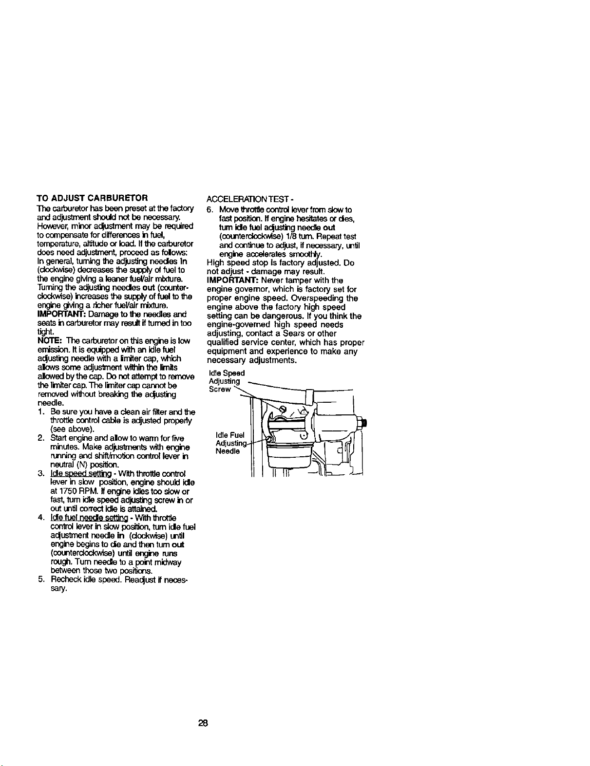
TO ADJUST CARBURETOR
The carburetorhasbeen presetat thefactory
and adjustment should not be necessary.
However,minor adjustment may be required
to c(_npensate for differences in fuel,
temperature,allJtudeor load. Ifthe carburetor
does need adjustment, proceedas folows:
In general, tuming the adjustingneedlesIn
(dockwLse)decreases the supply of fuel to
the enginegMng a leaner fuel/air mixture.
Tumingthe adjustingneedes out (counter-
clodw_se)increasesthe supplyof fuelto the
engine giving a richer fueVairmixture.
IMPORTANT: Damage to the needlesand
seatsincarburetor may resultifturnedin too
ti_t.
NOTE: The carburetor onthisengineislow
emission, if isequipped with an idlefuel
aclusting needle witha imiter cap, which
alows someadjus'cnantwithinthe limits
alowed bythe cap. Do not attemptto remove
the limitercap.The limitercap cannot be
removed without breaking the a_usting
needle.
1. Besureyou have a clean airfilterand the
throttlecootrolcableis adjustedproperly
(seeabove).
2. Start engine and alow to warm for five
minutes. Make adjustments with engine
running and shiftttoolJoncontrol lever in
neutral(N) pesi_on.
3. Idlest_=edsetting. Withthrottle control
lever in slow pos_on, engineshould kJe
at 1750 RPM. Ifengine idlestoo s!owor
fast, tum idle speed adjusting screw in or
out antJlcorrect idle is attained.
4. Idlefuelneedle set,rig- Withl_ret'_
contrelleverinslowposi_on,turnide fuel
a_ustmant needle In (clockwise)an_l
engine beginsto ole and than tum out
(_terdeskwise) untilengine rune
rough.Tum needleto a pointmidway
between those two pesiitons.
5. Resheck idlespeed. Reac_ustif neces-
sary.
ACCELERATIONTEST-
6. MovethrctlJecontrolleverfrom slowto
fast position.Ifengine hesitatesordins,
rum idlefuel ac_ustingneedle out
(counterclockwise)1/8 turn.Repeattest
andcoo'_nneto adjust, ifnecessary,an_JI
engineaccaieretessmoothly.
High speed stop is factory adjusted. Do
notadjust ° damage may result.
IMPORTANT: Never tamper withthe
engine governor, which is factory set for
proper engine speed. Overepeeding the
engine above the factory high speed
setting can bedangerous. Ifyou thinkthe
engine-governed high speed needs
adjusting, contacta Sears or other
qualified service center, which has proper
equipment and expedence to make any
necessary adjustments.
IdleSpeed
Adjusting
Screw
IdleFuel
Adjustin
Needle
28
mmediately prepare your tractor for
_torage at the end of the season or ff the
factor willnot be used for 30 days or
nore.
CAUTION: Never store the tractor
_ifh gasotinein the tank inside a betiding
_here fumes may reach an open flame or
_park. Allowthe engine to cool before
storing in any enclosure.
q_a,c'roR
Remove mower from tractor for winter
storage. When mower is to be storedfor
aperiod of time, clean itthoroughly,
remove all dirt, grease, leaves, etc. Store
in a clean, dry area.
1. Clean entire tractor (See =GLEANING"
in the Maintenance section ofthis
manual).
2. Inspect and replace belts, if necessary
(See belt replacement instructions in
the Service and Adjustments section
ofthis manual).
3. Lubricate as shown in the Mainte-
nance section of this manuel.
4. Be sure that all nuts, bolts end screws
are securely fastened. Inspect moving
parts for damage, breakage and wear.
Replace if necessary.
5. Touch up all rustedor chipped paint
surfaces;sand lightly before painting.
BATTERY
Fullycharge the battery for storage.
Aftera period of time in storage, battery
may require recharging.
• To help prevent corrosion and power
leakage dudng long periods of storage,
battery cables should be disconnected
and battery cleaned thoroughly (see
"TO CLEAN BATTERY AND TERMI-
NALS" in the Maintenance section of
this manual).
• After cleaning, leave cables discon-
nected and place cables where they
cannot come in contact with battery
terminals.
• If buttery isremoved fromtractor for
storage, do not storebattery directly on
concrete or damp surfaces.
ENGINE
FUEL SYSTEM
IMPORTANT: It isImportant toprevent
gum deposites from forming in essential
fuel system parts suchas carburetor, fuel
hose, ortank dudng storage.
Also, experience Indicates that alcohol
blended fuels (called gasohol or using
ethanol or methanol) can attract moisture
which leads to separation and formation
of acids duringstorage. Acidic gas can
damage the fuel system of and engine
while in storage.
1. Drain the fuel tank.
2. Start the engine and let if rununtil the
fuel lines and carburetor are empty.
* Never use engine or carburetor cleaner
productsin the fuel tank or permanent
damage may occur.
• Use fresh fuel nextseason.
NOTE: Fuel stabilizer is an acceptable
alternative in minimizing the formation of
fuel gum deposits dudng storage. Add
stabilizer to gasoline in fuel tank or
storage container. Always followthe mix
ratiofound on stabilizercontainer. Run
engine at least 10 minutes after adding
stabilizer to allow the stabilizerto reach
the carburetor. Do not drainthe gas tank
and carburetor if using fuel stabitizer.
ENGINE OIL
Drain oil (with engine warm) and replace
with clean engine oil. (See "ENGINE" in
the Maintenance section of this manual).
CYUNDER(S)
1. Remove spark plug(s).
2. Pour one ounce of oil through spark
plug hole(s) into cylinder(s).
3. Turn ignition key to "START" position
for a few seconds to distributeoil.
4. Replace with new spark plug(s).
OTHER
• Do not store gasoline from one season
to another.
• Replace your gasoline can if your can
starts to rust. Rust and/or dirt in your
gasoline will cause problems.
• If possible, store your tractor indoora
and cover it to give protection from dust
and dirt.
• Cover your tractor with a suitable
protective cover that does not retain
moisture. Do not use plastic. Plastic
cannot breathe which allows conden-
sationto form and will cause your
tractor to rust.
IMPORTANT: Never cover tractor white
engine and exhaust areas are stillwarm.
29

TROUBLESHOOTINGCHART
PROBLEM
Will not start
Hard to start
Engine will not
turn over
CAUSE
1. Out offuel.
2. Engine not "CHOKED"
properly.
3. Engine flooded.
4. Bad spark plug.
5. Dirty air filter.
6. Dirty fuel filter.
7. Water in fuel.
8. Loose or damaged wiring.
9. Carburetor out of adjustment.
10.Engine valves out of
adjustment.
1. Dirty airfilter.
2. Bad spark plug.
3. Weak or dead battery.
4. Dirty fuel filter.
5. Stale or dirty fuel.
6. Loose or damaged wiring.
7. Carburetor out of adjustment.
8. Engine valves out of
adjustment.
1. Brake pedal not
depressed
2. Attachment clutch is
engaged.
3. Weak or dead battery.
4. Blown fuse.
5. Corroded battery terminals.
6. Loose or damaged wiring.
7. Faulty ignition switch.
8. Faulty solenoid or starter.
CORRECTION
1. Fillfuel tank.
2. See=TO START ENGINE"
in Operation section.
3. Wait several minutes before
attemptingto start.
4. Replace spark plug.
i 5. Clean/replace air filter.
6. Replace fuel filter.
7. Drain fuel tank and carbure-
tor, refilltankwith fresh
gasoline and replace fuel
rilter.
8. Check all wiring.
9. See "To Adjust Carburetor"
in Service Adjustments
section.
10.Contact a Sears or other
qualified service center.
1. Clean/replace air filter.
2. Replace spark plug.
3. Recharge or replace battery.
4. Replace fuel filter.
5. Drain fuel tank and refillwith
fresh gasoline.
6. Check all wiring.
7. See =ToAdjust Carburetor"in
Service Adjustments
section.
8. Contact a Sears or other
qualified service center.
1. Depress brake pedal.
9. Faulty operator presence
swltch(es).
Englnacllcksbut 1. Weak or dead battery.
will not start !2. Corroded battery terminals.
13. Loose or damaged wiring.
4. Faulty solenoid or starter.
Loss of power 1. Cutting too much grass/too 1. Set in "Higher Cut" position/
fast. reduce speed.
2. Throttle in "CHOKE" 2. Adjust throttle control.
position.
3O
2. Disengage attachment
clutch.
3. Recharge or replace battery.
4. Replace fuse.
5. Clean battery terminals.
6. Check all wiring.
7. Check/replace ignition
switch.
8. Check/replace solenoid or
starter.
9. Contact a Sears or other
qualified service center.
f. Recharge or replace battery,
2, Clean battery terminals.
3. Check all wiring.
4. Check/replace solenoid or
starter.
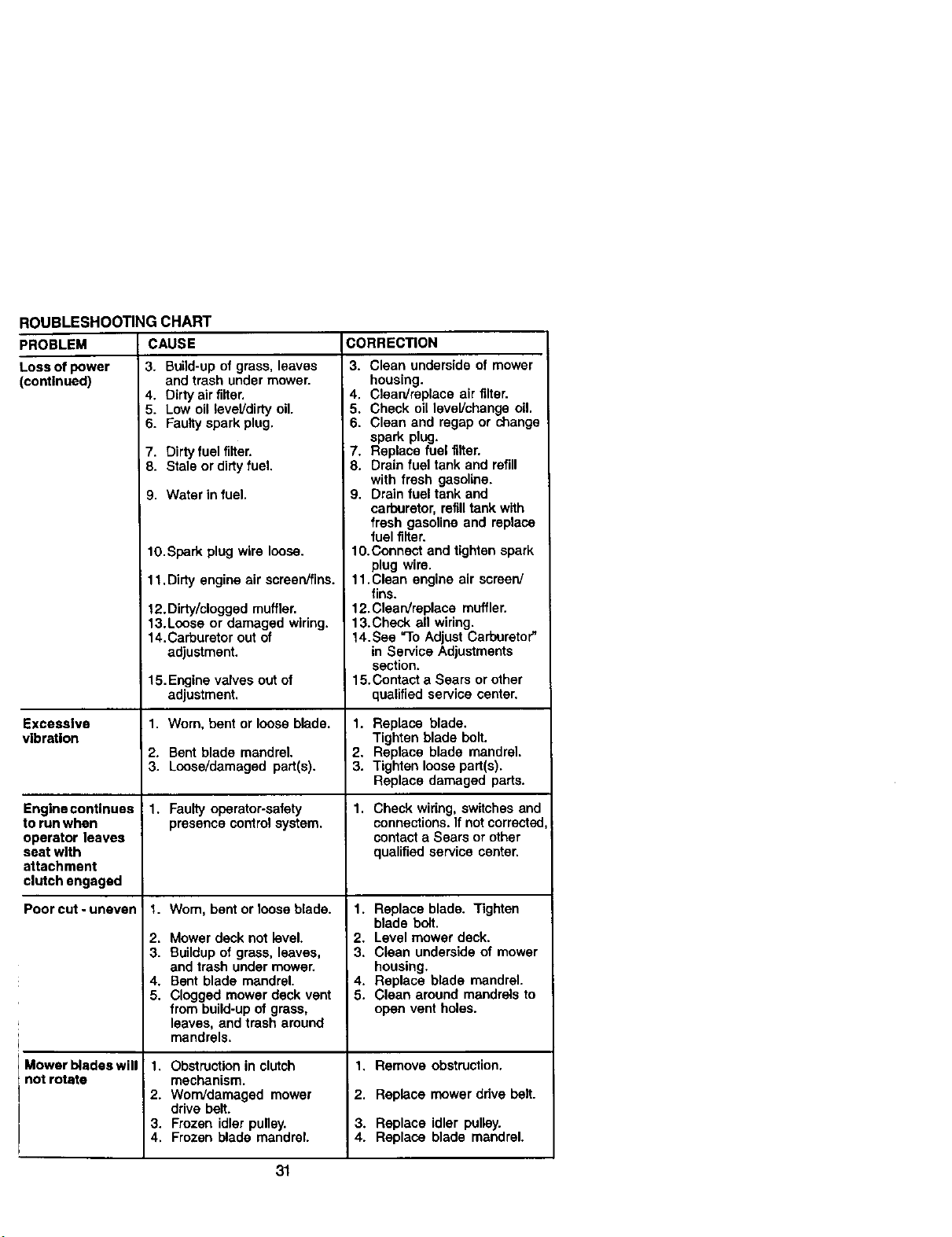
ROUBLESHOOTING CHART
PROBLEM
Loss of power
(continued)
Excessive
vibration
CAUSE
3. Build-up of grass, leaves
and trash under mower.
4. Dirty air filter.
5. Low oil level!dirty oil.
6. Faulty spark plug.
Engine continues
to run when
operator leaves
seat with
attachment
clutch engaged
Poorcut-uneven
7. Dirty fuel filter.
8. Stale or dirty fuel.
9. Water in fuel.
10.Spark plug wire loose.
i 11. Dirty engine air screenffins.
12.Dirty/clogged muffler.
13.Loose or damaged wiring.
14.Carburetor out of
adjustment.
15.Engine valves out of
adjustment.
1. Wom, bent or loose blade.
2. Bent blade mandrel.
3. Loose/damaged part(s).
1. Faultyoperator-safety
presence controlsystem.
1. Wom, bent or loose blade.
2. Mower deck not level.
3. Buildupof grass, leaves,
and trash under mower.
4. Bent blade mandrel.
5. Clogged mower deck vent
from build-upof grass,
leaves, and trash around
mandrels.
Mower blades will I.
not rotate
2.
3.
4.
Obstruction in clutch
mechanism.
Worn/damaged mower
drive belt.
Frozen idler pulley.
Frozen blade mandrel.
CORRECTION
3. Clean underside of mower
housing.
4. Claan/replace air filter.
5. Check oil level/change oil.
6. Clean and regap or change
spark plug.
7. Replace fuel filter.
8. Drain fuel tank and refill
with fresh gasoline.
9. Drain fuel tank and
carburetor, refilltank with
fresh gasoline and replace
fuel filter.
10.Connect and tighten spark
plug wire.
11. Clean engine air screen/
fins.
12.Clearv'replace muffler.
13.Check all wiring.
14.Sea "To Adjust Carburetor"
in Service Adjustments
section.
15.Contact a Sears or other
qualified service center.
1. Replace blade.
Tighten blade bolt.
2. Replace blade mandrel.
3. Tighten loose part(s).
Replace damaged parts.
1. Check wiring, switches and
connections. If not corrected
contact a Sears or other
qualified service center.
1. Replace blade. Tighten
blade bolt.
2. Level mower deck.
3. Clean underside of mower
housing.
4. Replace blade mandrel.
5. Clean around mandrels to
open vent holes.
1. Remove obstruction.
2. Replace mower ddve belt.
3. Replace idler pulley.
4. Replace blade mandrel.
31
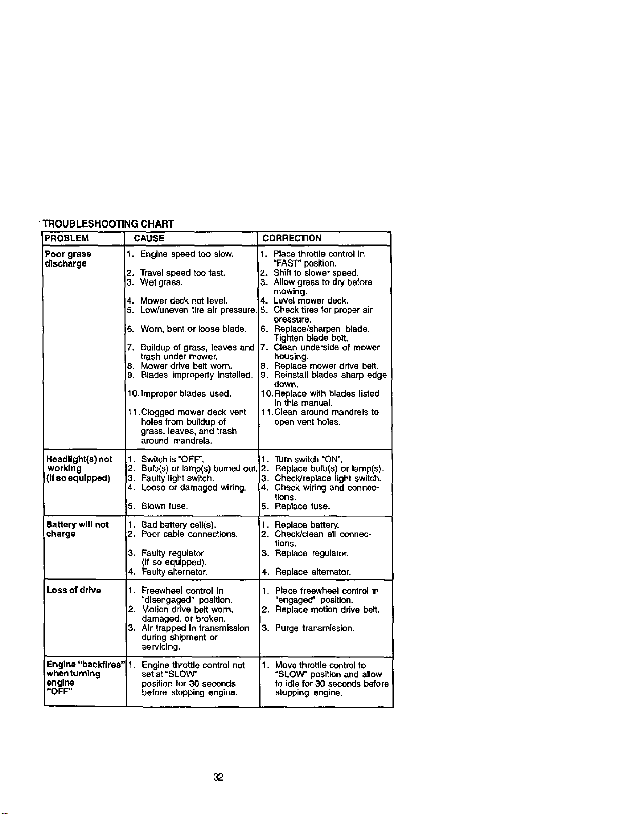
PROBLEM
Poor grass
discharge
TROUBLESHOOTING CHART
CAUSE
1. Engine speedtoosiow.
Headlight(s) not
working
(ifso equipped)
Battery will not
charge
Loss of drive
2. Travel speed too fast.
3. Wet grass.
4. Mower deck not level.
5. Low/uneven tire air pressure.
6. Worn, bent or loose blade.
7. Buildupof grass, leaves and
trash under mower.
8. Mower drive belt worn.
9. Blades improperly installed.
10.Improper blades used.
11. Clogged mower deck vent
holes from buildup of
grass, leaves, and trash
around mandrels.
1. Switch is"OFF",
2. Bulb(s) or lamp(s) burnedout.
3. Faulty light switch.
4. Loose or damaged wiring.
5. Blown fuse.
1. Bad battery cell(s).
2. Poor cable connections.
3. Faulty regulator
(if so equipped).
4. Faulty alternator.
1. Freewheel control in
"disengaged" position.
2. Motion drive belt worn,
damaged, or broken.
3. Air trapped in transmission
during shipment or
servicing.
CORRECTION
t. Place throttlecontrol in
"FAST" position.
2. Shift to slower speed.
3. Allow grass to dry before
mowing.
4. Level mower deck.
5. Check tires for proper air
pressure.
6. Replace/sharpen blade.
Tighten blade bolt.
7. Clean underside of mower
housing.
8. Replace mower drive belt.
9. Reinstall blades sharp edge
down.
10. Replace with blades listed
in this manual.
11.Clean around mandrels to
open vent holes.
1. Turn switch"ON".
2. Replace bulb(s) or lamp(s).
3. Check/raplace light switch.
4. Check wiring and connec-
tions.
5. Replace fuse.
1. Replace battery.
2. Check/clean all connec-
tions.
3. Replace regulator.
4. Replace alternator.
1. Place freewheel control in
"engaged" position.
2. Replace motion drive belt.
3. Purge transmission.
Engine"backfires" 1. Engine throttle control not 1. Move throttlecontrolto
whenturnlng set at "SLOW" "SLOW" position and allow
engine positionfor 30 seconds to idlefor 30 seconds befor_
"OFF" before stopping engine, stopping engine.
32
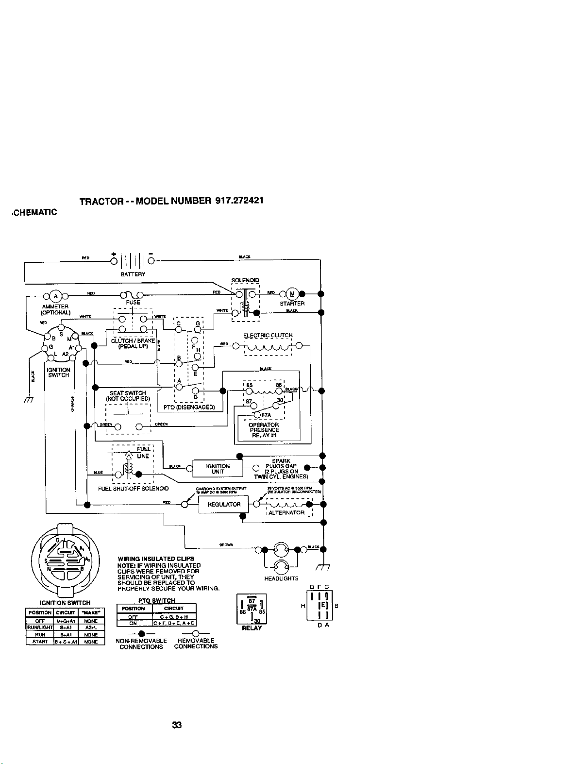
;CHEMA_C
TRACTOR -- MODEL NUMBER 917.272421
WIRING INSULATED CUPS I _ I
NOTE: IF WIRING INSULATED
CLIPS WERE REMOVED FOR
SERVICING OF UNIT, THEY HEADLIGHTS
SHOULD BE REPLACED TO
PROPERLY SECURE YOUR WIRING. G F C
PO6mON CIRCUrr H B
OFF C +G=B_. H
ON C+ F,B*E,A÷D RELAY D A
NON-REMOVABLE REMOVABLE
CONNECTIONS CONNECTIONS
IGNmON SWITCH
33

ELECTRICAL
TRACTOR - - MODEL NUMBER 917.272421
I i
27
34
t
i
J
J
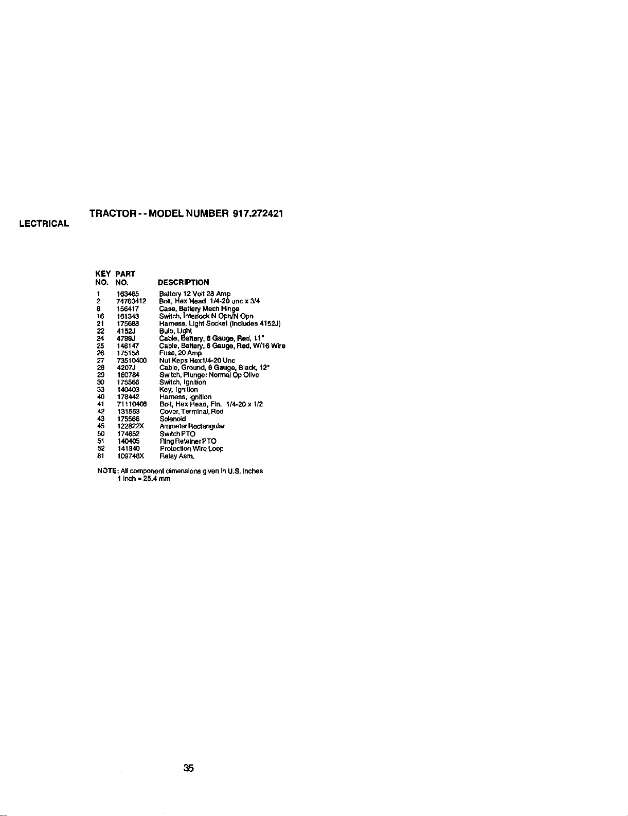
LECTRICAL
TRACTOR - - MODEL NUMBER 917.272421
KEY PART
NO. NO. DESCRIPTION
1 163465 Battery 12 Vblt 28 Amp
2 74760412 BoE, Hex Head 1/4-20 uricx 3/4
8 156417 Case, Battery Mech Hinge
16 161343 Switch. _ntedock N Opr_l Opn
21 175688 Harness, Light Socket (Includes 4152J)
22 4152J Bulb, Light
24 4799J Cable, Battery, 6 Gauge, Red, t1"
25 146147 Cable, Battery, E Gauge, Red, w/16 Wire
26 175158 Fuse,20 Amp
27 73510400 Nut Keps Hexl/4-20 Unc
28 4207J Cable, Ground, 6 Gau0e, Blad<, 12"
29 160784 Switch, Plunger Norn_l Op Olive
30 175566 Switch, Ignition
33 140403 Key, Ignition
40 178442 Harness, Ignition
41 71t10406 Bclt, Hex Head, Fin. I/4-20 x 1/2
42 131563 Cover, Terminal, Red
43 175566 Soler_id
45 122822X Ammeter Rectangular
50 174652 Switch PTO
51 1404_5 Ring Retainer PTO
52 141940 Protectlor_V_ireLoop
51 109748X Relay Asnn.
NOTE: All component dimensions given In U.S. inches
1 inch = 25,4 mrn
35
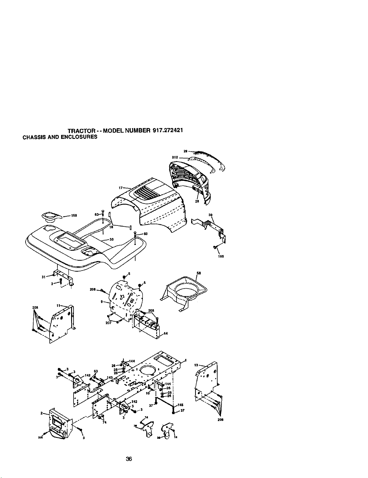
TRACTOR -- MODEL NUMBER 917.272421
CHASSISAND ENCLOSURES
6O
74
206
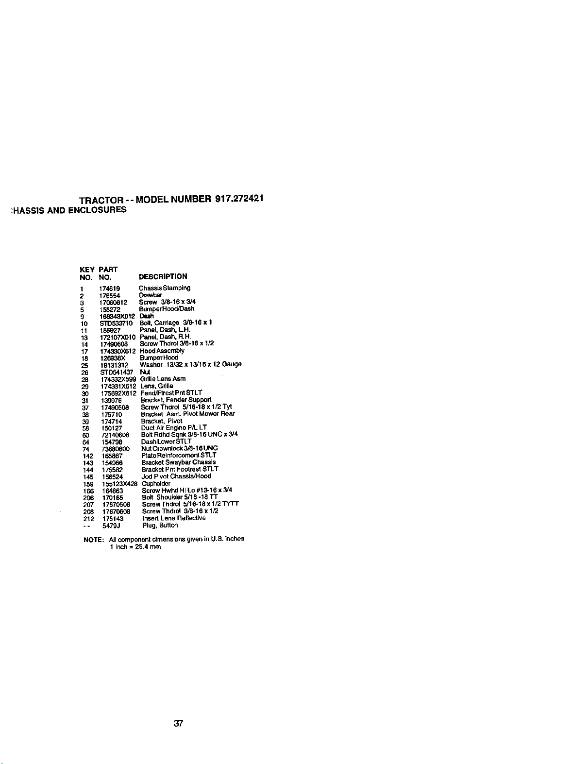
TRACTOR -- MODEL NUMBER 917,272421
:HASSIS AND ENCLOSURES
KEY pART
NO, NO. DESCRIPTION
1 174619 Chasels Stamping
2 176554 Drawbar
3 17060612 Screw 3/8-16 x 3/4
5 155272 Bumper Hood/Dash
9 168343X012 Dash
10 S_)533710 Bo!t, Carriage 3/8-16 x 1
11 155927 Panel, Dash. LH.
13 172107X010 P_nel, Dash, R.H.
14 17490608 Screw Thdrol 3/8-16 x 1/2
17 174330X612 HoodAssembly
18 126938X Bumper Hood
25 19131312 Washer 13/32 x 13/16 x 12 Gauge
26 STD541437 NUt
28 174332X599 Grille Lens Asm
29 174331)(612 Lens, Gdlie
30 175692X612 Fend/Fb'est Pnt STLT
31 139976 Brackot, Fender Support
37 17490508 Screw Thdrol 5/16-18 x 1/2 Tyt
38 175710 Bracket Asm. Pivot Mower Rear
39 174714 Bracket, Pivot
58 150127 Duct Air Engine P/L LT
60 72140606 Bolt Rdhd Sqnk 3/8-16 UNC x 3/4
64 154798 Dash Lower STLT
74 73680600 NutCrownlock 3/8-16 UNC
142 165867 PlateRelnforcernent STLT
143 154966 Bracket Swaybar Chassis
144 175582 Brackot pnt Footrest STLT
145 156524 Jod Pivot Chassis/Hood
159 155123X428 Cuphelck_r
166 164863 Screw Hwhd Hi Lo #13-16 x 3/4
206 170165 Bdt Shouider5/16-18Tl"
207 17670508 Screw Tndrol 5/16-18 x 1/2 "rYTT
2C_ 17670608 Screw Thdrol 3_-16 x 1/2
212 175143 Irked Lens Reflective
-. 5479J Plug, Button
NOTE: All component dimensions given in U.S. Inches
1 inch = 25.4 mm
37
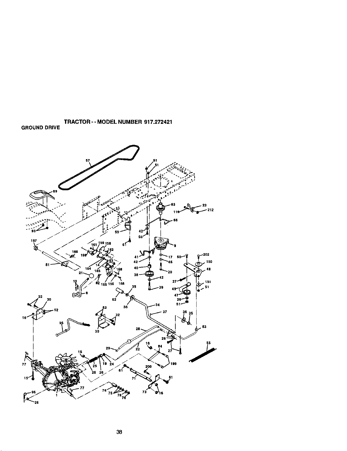
TRACTOR- - MODEL NUMBER 917.272421
GROUNDDRIVE
77
55
26
61
38
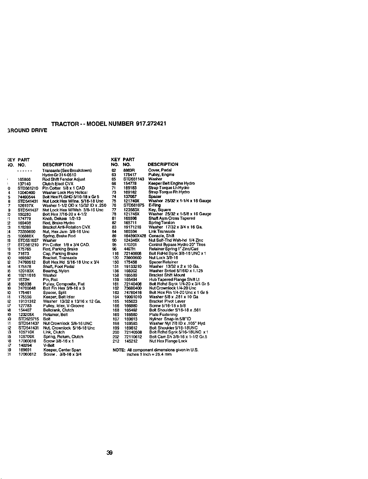
TRACTOR-- MODEL NUMBER 917.272421
;ROUND DRIVE
_.EY PART KEY
|O. NO. DESCRIPTION NO.
...... Tmnsaxte (See Breakdown) 62
HydroGr314_510 63
165865 Rod Shilt Fender Adjust 65
137140 Clutch Elect CVX 66
0 STD561210 PinCottar 1/TxlCAD 71
4 10040400 Washer Lock HW HetJcal 73
5 74490544 Bolt Hex FLGHD 5/16-18 x Gr 5 74
6 S'FD541431 Nut Lock Hex W/ins. 5/16-18 Unc 75
7 126197)( Washer 1-1/20D x 15/32 [D x .250 76
9 $1D541437 Nut Lock Hex WPNsh 3/6-16 Unc 77
_0 150280 Bolt Hex 7/16-20 x 4-1/2 78
!I 174779 Knob, Deluxe 1/2-13 61
_2 169498 Rod, Brake Hydro 82
_3 178289 Bracket Anti-Rotation CVX 83
!4 73350600 Nut, Hex Jam 5/6-16 Unc 84
_5 106888X Bpdng, Brake Rod 89
!6 STD551037 Washer 90 124346)(
_7 STD561210 PinCctter 1/Sxs/4CAD. _5 170201
!8 175765 Rod, Parking Brake 96 4497H
F3 71673 Cap, Parking Brake 116 72140608
_0 159592 Bracket, Tr&nsaxle 120 73.90(000
_2 74760512 Boll Hex Hd 5/16-18 Urtcx 3/4 150 175456
;4 175578 Sheft, Foot Pedal 151 13133210
_5 t20183X Bearing, Nylon 156 1660_
_6 19211616 Washer 158 165589
37 1572H Pin, Rail 159 165494
_8 165936 Pulley, Composite, Flat 151 7214040_
}9 74760648 Bolt Fin Hex 3/8-16 x 3 1_ 73680400
!O 175461 Spacer, Split 163 74760416
11 175556 Keeper, Bolt idler 164 19091010
12 19131312 Washer 13/32 x 13/16 x 12 Ga. 165 165623
17 127783 Pulley, Idler, V-Groove 166 166880
_8 154407 Bellcr_nk, Clutch 168 165492
_9 123_05X Retainer, Bait 169 165580
_0 S1_523715 Bed 197 169613
_1 S]_541437 NutCrownlock 3/6.16UNC 198 169593
_2 STD541431 Nut, Crownlock 5/16-16Unc 199 169612
_3 105710)( Link, CIotch 200 72140506
_5 105709X Spring, Return, Clutch 2(_ 72110612
;6 17060616 Screw 3/8-16 x 1 212 145212
_7 140294 V-Bait
_9 169691 Keeger, Center Span
31 17060612 Screw. 3/8-16 x 3/4
PART
NO. DESCRIPTION
8883R Cover, Pedal
175417 pulley, Engine
STD551143 Washer
154778 Keeper Belt Engine Hydro
169183 Strap Terque Lh Hydro
169182 Strap Torque Rh Hy_lro
137657 Spao_
121749X Washer 25/32 x 1-1/4 x 16 Gauge
STD581075 E-Ring
123583X Key, Square
121748X Washer 25/32 x 1-5/8 x 16 Gauge
! 65596 Shat_ Asm Cross Tapered
165711 Spdng Torsion
19171216 Washer 17/32 x 5/4 x 16 Ga.
169594 Link Transaxte
164890X428 CoPaole, Shift
Nut Self-Thd Wsh-hd 1/4 Zlnc
Control Bypass Hydro 20" Tires
Retainer Spring t" ZInc/Ced
Bed RdHd Sqnk 3/8-16 UNC x 1
Nut Lock 3/8-16
Spacer Retainer
Washer 13/32 x 2 x 10 Ga.
Washer Srrted 5/161D x 1.125
Bracket Shift Mount
Hub Tapered Flange Shilt Lt
Bolt Rdhd Sqnk 1/4-20 x 3/4 Gr 5
Nut Crownlock 1/4-20 Unc
Bed Hex FLn1/4-20 Unc x 1 Gr 6
Washer 6/8 x .281 x 10 Ga
Bracket Pivot Lever
Screw 5/16-18 x 5/6
BottShoulder 5/18-16 x .561
Plate Fastening
Nyllner Snap-In 5/8"10
Washer Nyl 7/8 ID x .105" Hyd
Bolt Shoulder 5/16.18UNC
Bolt Rdhd Sgnk 5/1 6.18UNC x 1
Bolt Cart Sh 3_-16 x 1-1/2 Gr.5
Nut Hex Flange Lock
NOTE: All component dimenslor'_ given in U.B.
inches 1 inch = 25.4 mm
39
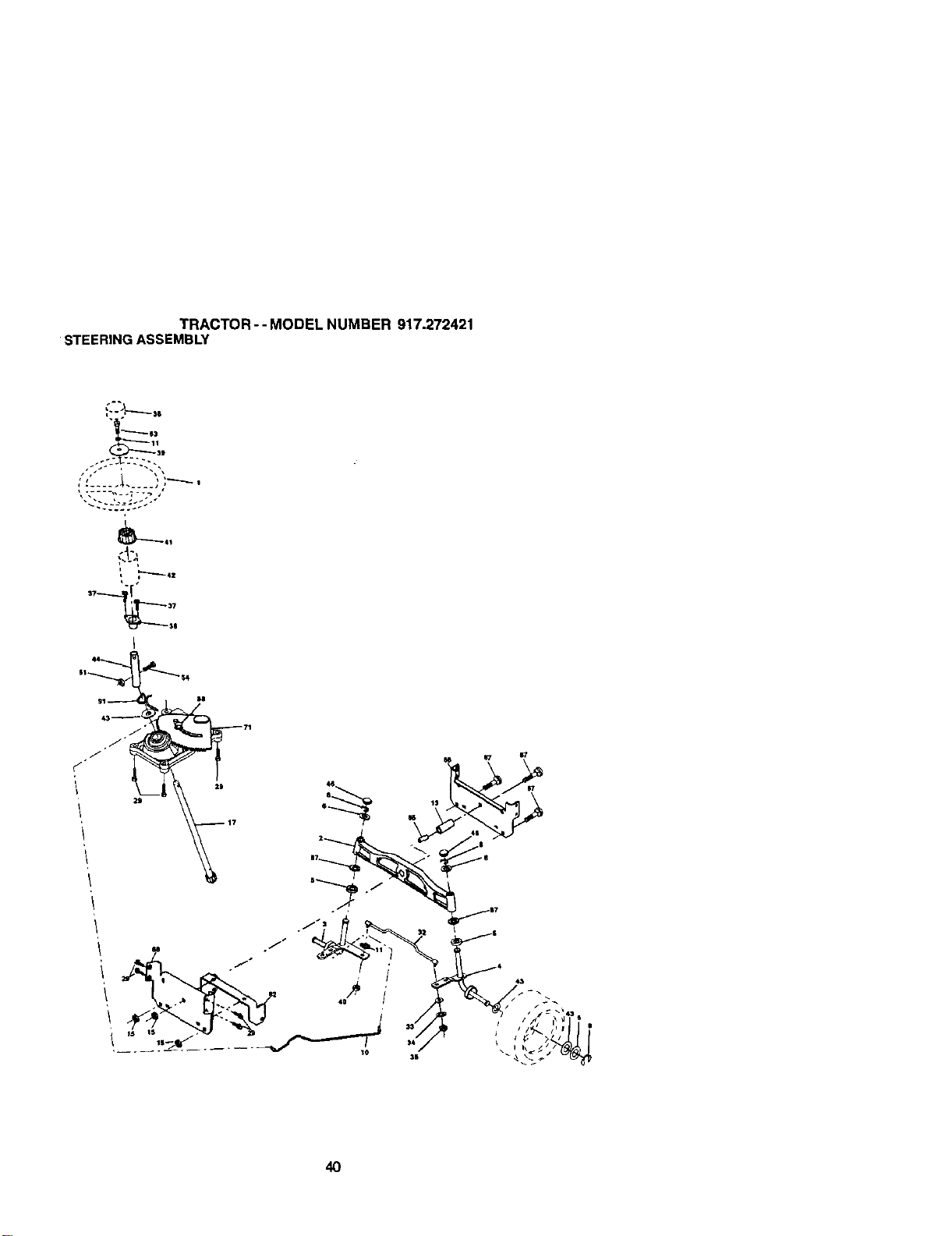
TRACTOR-- MODEL NUMBER 917.272421
STEERINGASSEMBLY
_e3
40
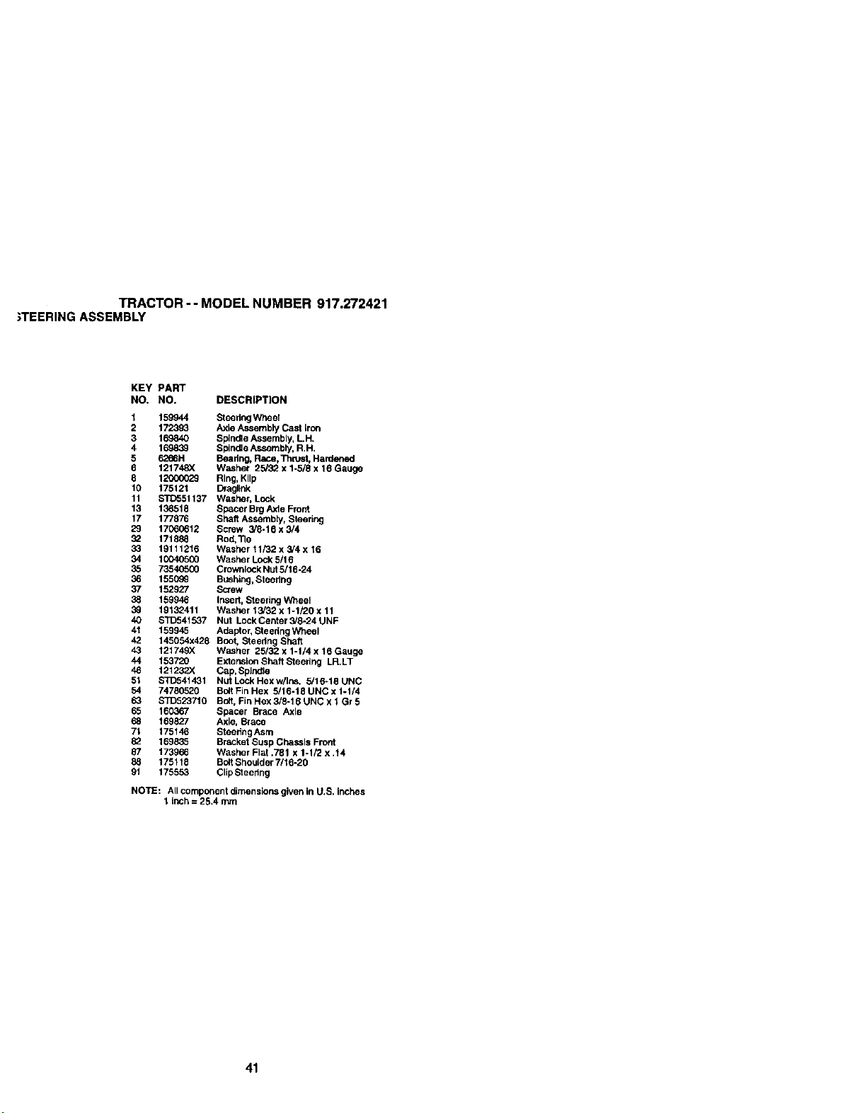
TRACTOR -- MODEL NUMBER 917.272421
;TEERING ASSEMBLY
KEY PART
NO. NO. DESCRIPTION
I
2
3
4
5
9
9
10
11
13
17
29
39
33
34
35
36
37
38
39
4O
41
42
43
44
46
51
54
63
65
68
7t
39
87
88
91
159944 SteeringWheer
172393 Axle Assembly Cast iron
169840 Spindle Assembly, LH.
169839 Spindle Assembly, R.H.
6266H Bearing, R_.e, Thrust,Hardened
121748X Washer 25/32 x 1-5/8 x 16 Gauge
12000029 Ring,KIIp
175121 Dragllnk
s'rD551137 Washer, Lock
136518 Sgecer BrgAxle Front
177876 Shaft Assembly, Steering
17060612 Screw 3/8-19 x 3/4
171888 Rod.'rle
19111216 Washer t 1/32 x 3/4 x 16
10040500 Washer Lock 5/16
73540500 Crownlock Nut 5/16-24
1550c_ Bushing, Steering
152927 Screw
159946 Insert, Steering Wheel
19139411 Washer 15/32 x 1-1/20 x 11
STD541537 Nut LockCenter 3/8-24 UNF
159945 Adaptor, Steedng Wheel
145054x428 Boot, Steedng Shaft
12t 749X Washer 25/32 x 1-1/4 x 16 Gauge
153720 Extensiofl Shaft Steering LR.LT
121232X Ca.p,Spindle
STD541431 NutLockHexw/Ins+ 5/16-18UNC
74780520 Bolt Fin Hex 5/16-18 UNC x 1-1/4
STD523710 Bolt, Fin Hex 3/8-18 UNC x 1 Gr 5
160367 Spacer Brace Axle
169827 Axle, Brace
175146 Steedng Asm
169835 Brsckrd Susp Chassis Front
173966 Washer Flat +781 x 1-1/2 x .14
175118 BcltShoulder 7/16-20
175553 ClipSteedng
NOTE: All component dimensions given in U.S. inches
1 inch = 25.4 mm
41
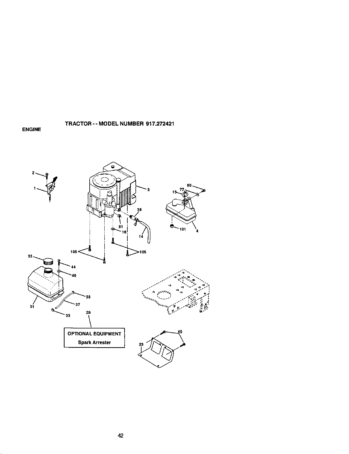
ENGINE
TRACTOR -- MODEL NUMBER 917.272421
38
OPTIONAL EQUIPMENT
Spark Arrester
8O
I 23

ENGINE
TRACTOR -- MODEL NUMBER 917.272421
KEY PART
NO. NO, DESCRIPTION
1 170548 Control,Throttle
2 1"/720410 Screw, Hex Head, Thlead Cutting 1/4-20 x 5_
3 ...... Engine, (See Breakdown) Kohler Model No. CV492-27506
4 159420 Muffler
13 12-O41-03 Gasket Kohler
14 148456 Tube Drain Oil Easy
16 $1D551237 Washer
23 169837 Shield BrrVDbrGuard
29 137180 Arrestor, Spark
31 10_(_X Tank, Fuel
32 158990 Cap Assembly, Fuel Sears, Vented
33 123487X Clamp,Hose
37 137040 Line, Fuel
38 148315 Plug, Dra_nOil Easy
44 17670412 Screw, Hex Washer Heed, Thd., Roll. 1/4-20 x 3/4
45 17(XX3612 Screw Hex Wsh TT_dr3/6- I 5 x 3/4
46 19_91416 Washer 9/32 x 7/5 x 15 Gauge
77 19101216 Washer 5/16 x 3/4 x 16 Ga.
80 74760508 Boit Hex Hd 5/16-15 Unc x 1/2
81 73510400 Nut Keps Hex 1/4-20Unc
101 M73C30800 Nut Flan-ge M6-1.25 Non-Lk Zinc
105 17120615 Screw 3_-16 x 1
NOTE: Atlccrr_0onentdimensions given in U.S. inches
I Inch= 25.4 mm
43
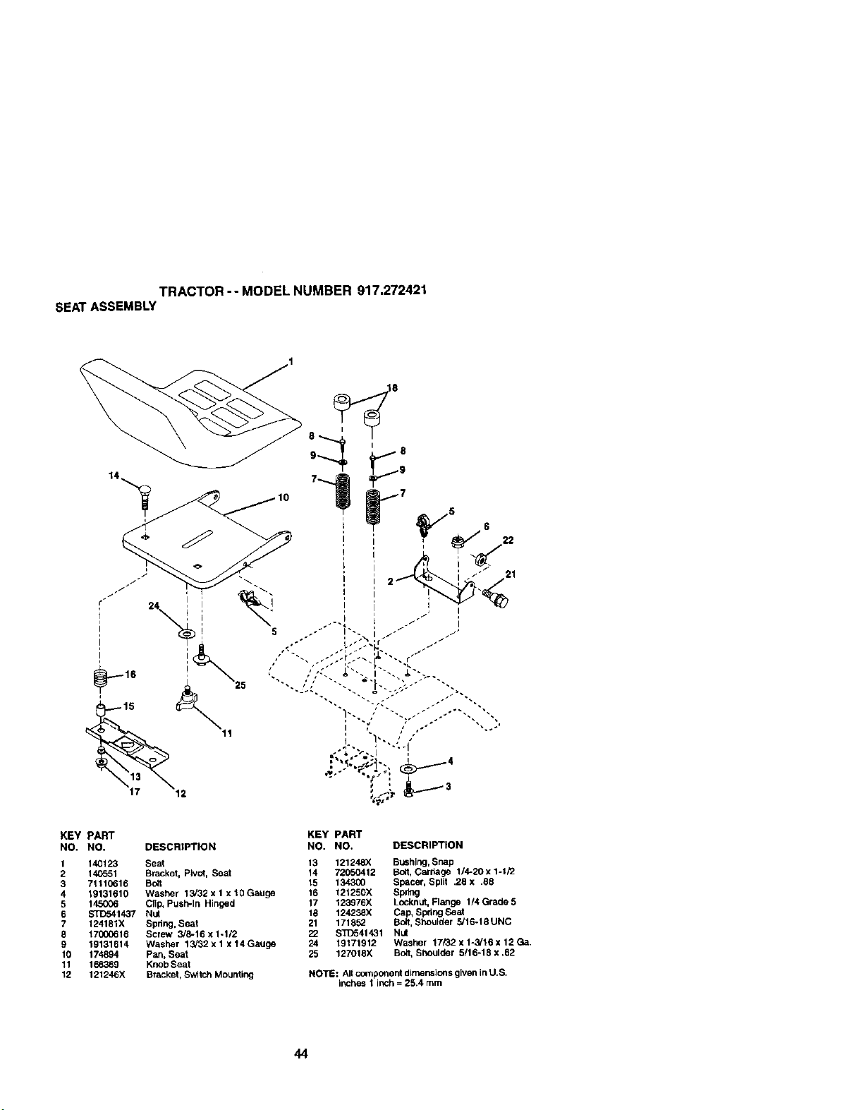
TRACTOR-- MODEL NUMBER 917.272421
SEATASSEMBLY
KEY PART KEY PART
NO. NO. DESCRIPTION NO. NO. DESCRIPTION
1 140123 Seat 13 121248X Bushing, Snap
2 140_51 Bracket, Ptvo(, Seat 14 72050412 Bolt, Cardage 1/4-20 x 1-1/2
3 71110616 Bolt 15 134300 Spacer, Split .28 x .68
4 19131610 Washer 13/32 x 1 x 10 Gauge 16 121250X Spring
5 145006 Cltp, PusPPIn Hinged 17 123976X Locknut, Flange 1/4 Grade 5
6 _1437 Nut 18 124238X Cap, Spdng Saat
7 124161X Spring, Seat 21 171852 BoB,Shoulder _16-18 UNC
6 17000616 Screw 3/8-15 x 1-1/2 22 S_41431 Nut
9 19131614 Washer 13/32xlx14Gauge 24 19171912 Washer 17i32x1-3/_6x 12Ga.
10 174894 Pan, Seat 25 127018X Bolt, Shoulder 5/16-18 x .62
11 1_369 Knob Seat
12 121246X Bracket, Switch Mounting NOTE: Aircomponent dimensions given in U.S.
inches I inch = 25.4 mrn
44
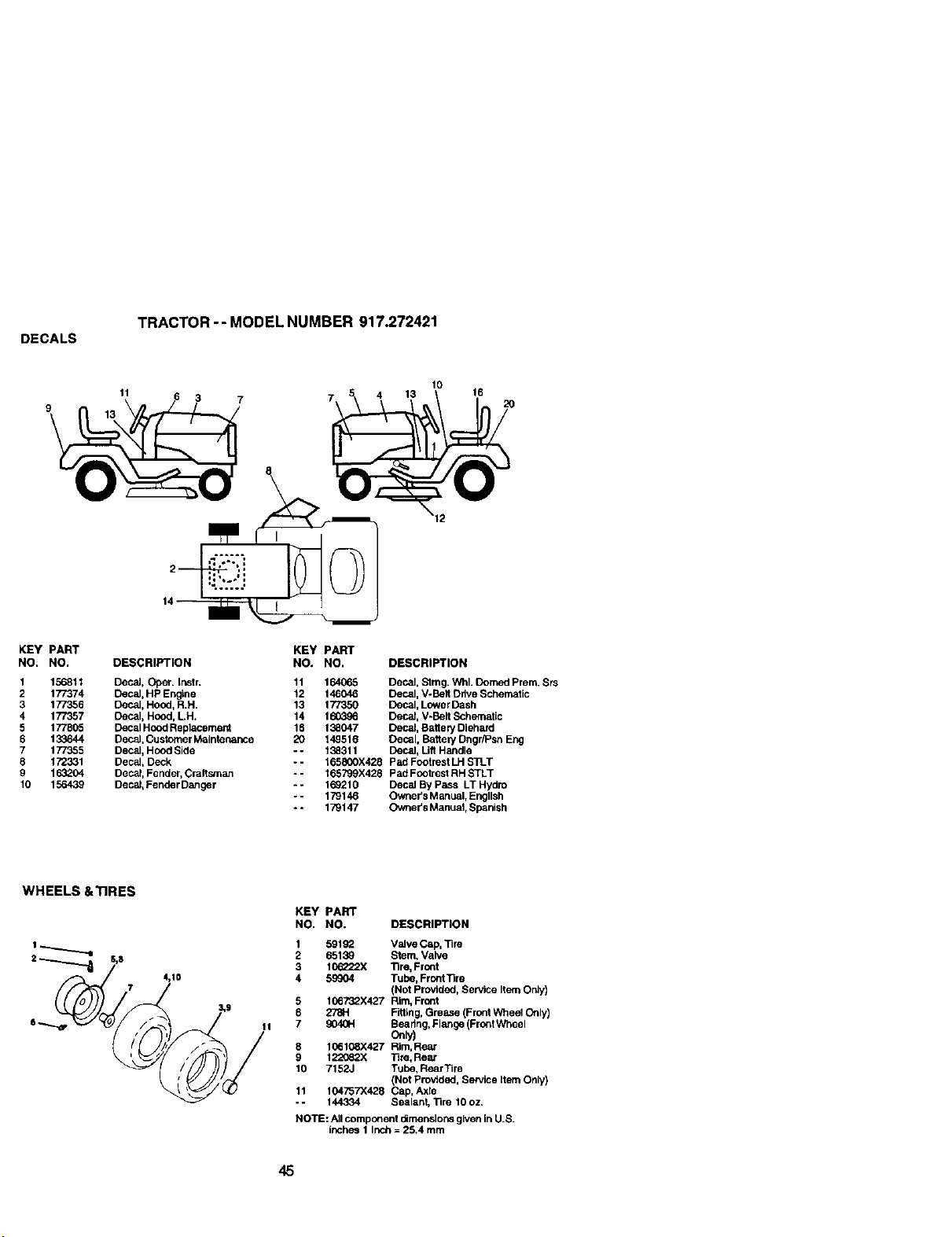
DECALS
TRACTOR -- MODEL NUMBER 917.272421
10
11 6 3 7 7 5 4 13 16 20
-::--:-.
KEY PART
NO. NO.
1 156811
2 177374
3 177356
4 177357
5 177805
6 133644
7 177355
8 172331
9 163204
10 156439
KEY PART
DESCRIPTION NO. NO. DESCRIPTION
Decal, (}per. instr. 11 164065 Decal, Stmg. Whl. Domed Prem. Srs
Decal, HP Engine 12 146046 Decal. V-Belt Drive Schematic
Decal, Hood, R.H. 13 177350 Decal, Lower Dash
Decal, Hood, LH. 14 160396 Decal, V-Belt Schematic
Decal Hood Replaceme_ 16 138047 Decal, Battery Diehard
Decal, Customer Maintenance 20 148516 Decal, BatteP/Dngr/Psn Eng
Decal, Hood Side - - 138311 Decal, Uft Handle
Decal, Deck - - 165800X428 Pad Footrest LH STLT
Decal, Feoder, Craftsman -- 165799X428 Pad Footrest RH STLT
Decal, Fender Danger - - 169210 Decal By Pass LT Hydro
- - 179146 Owner's M anual, Engllsh
- - 179147 Owner's Manual, Spanish
WHEELS &TIRES
KEY PART
NO. NO. DESCRIPTION
1 59182 Valve Dep, Tim
2 65139 Stern, Valve
3 10_222X llre, Front
4 59904 Tuod, FrontTire
(Not Provided, Service Item Ordy)
5 106732X427 Rim, Front
6 278H Fitting, Grease (Front Wheal Only)
7 9040H Beadng, Flange (Front Wheal
one)
8 106108X427 Rim, Rear
9 122082X Tire, Rear
10 7152J Tube, Rear Tire
(Not Provtdod, Service item Only)
tt 104757X428 Cap, Aale
- - 144334 Sealant, Tire 10 oz.
NOTE: All cornpc_ent dlmenslons given in U.S.
Ittches 1 Inch = 25.4 mm
45
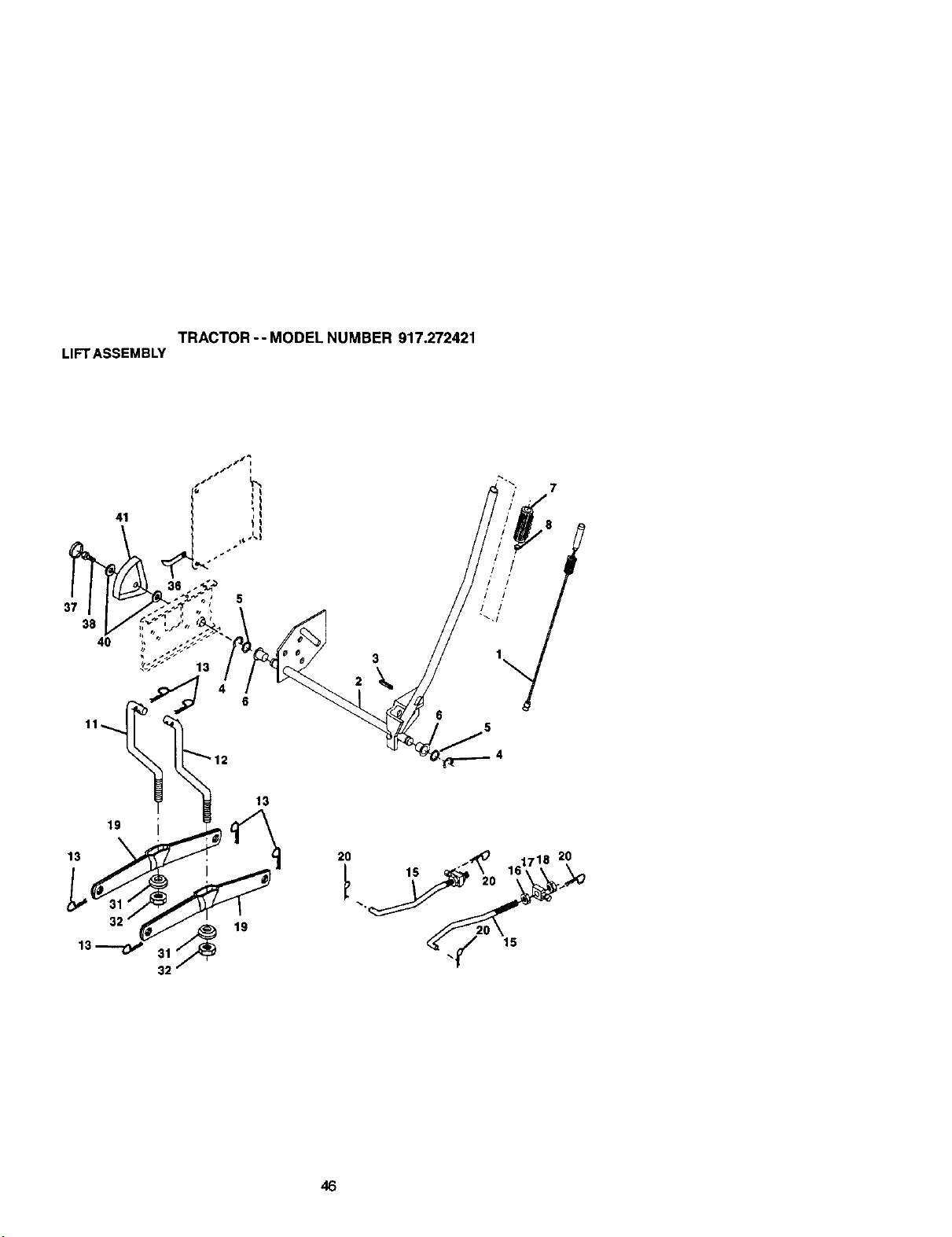
TRACTOR-- MODEL NUMBER 917.272421
LIFTASSEMBLY
19
13
32
13
19
2O
15
15
20
46
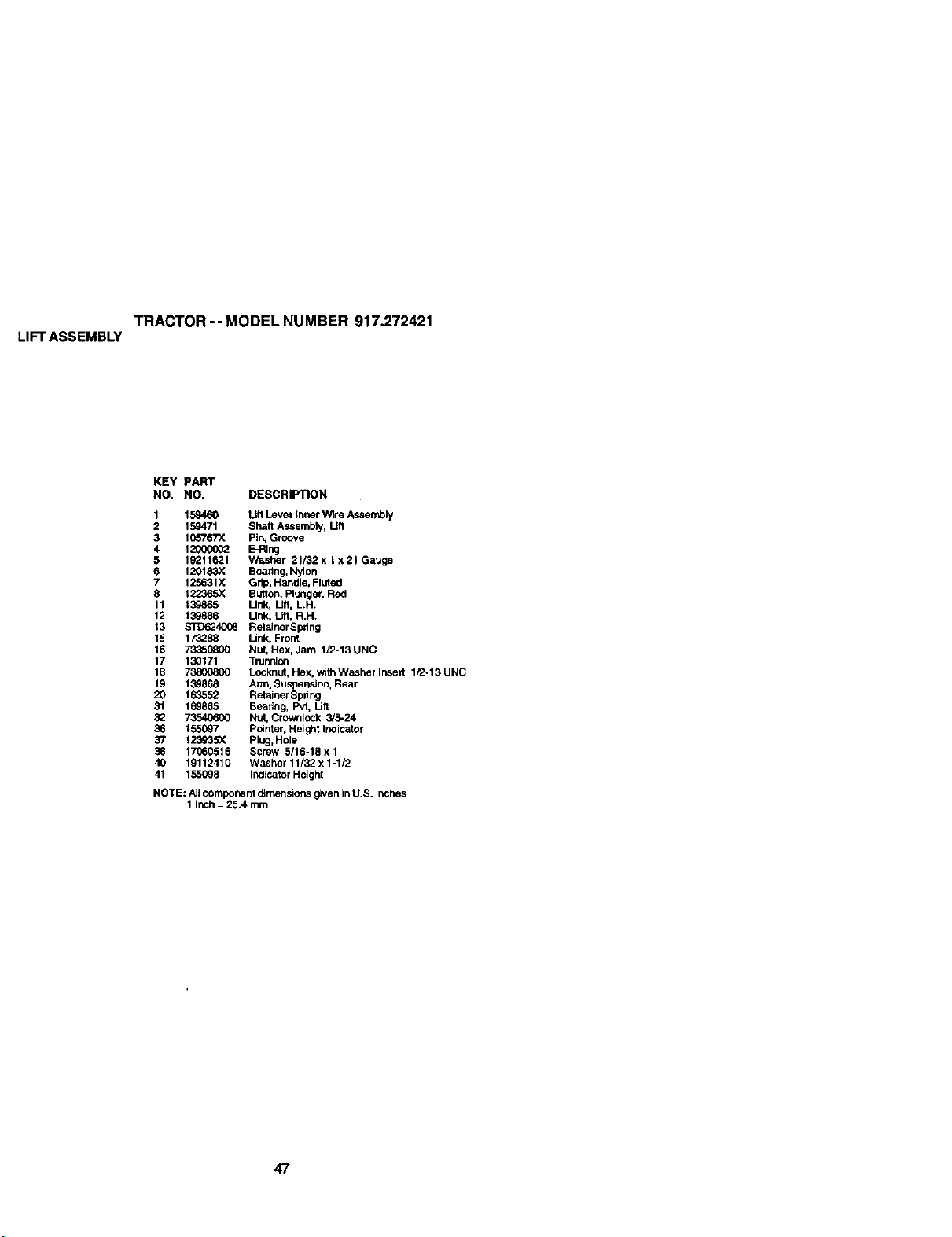
TRACTOR-- MODEL NUMBER 917.272421
LIFTASSEMBLY
KEY PART
NO, NO. DESCRIPTION
1 159460 Lift Lever Inner W_re Assembly
2 159471 Shaft Assembly, Lift
3 I fto'767X Pin, Groove
4 120000(_ E-Rlug
5 19211621 Washer 21/32 x t x 21 Gauge
6 120183X Beadng, Nylon
7 125631X Gdp, Handle, Fluted
8 122_5X BL_oot Plunger, Red
11 139865 Link, Lift, LH.
12 139866 Link, Lift, R.H.
13 STD6240_ RelalnerSpdng
15 173288 Link, Front
16 73350800 Nut, Hex, Jam 1/2-13 UNC
17 130171 Trunoi_
18 73800800 Locknut, Hex, with Washer Irked 1/2-13 UNC
19 139868 Arm, Suspension, Rear
20 163552 Retainer Spriug
31 169865 Beadng, Pvt, Lilt
32 73540600 Nut, Crownlock 3/8-24
36 155097 Pointer, Height Indicator
123935X Plug, Hole
38 17(;60516 Screw 5/16-18 x 1
40 19112410 Washer 11/32 x 1-1/2
41 155098 Indicator Height
NOTE: All component oimensior_s given inU.S. inches
1 Inch = 25.4 turn
47
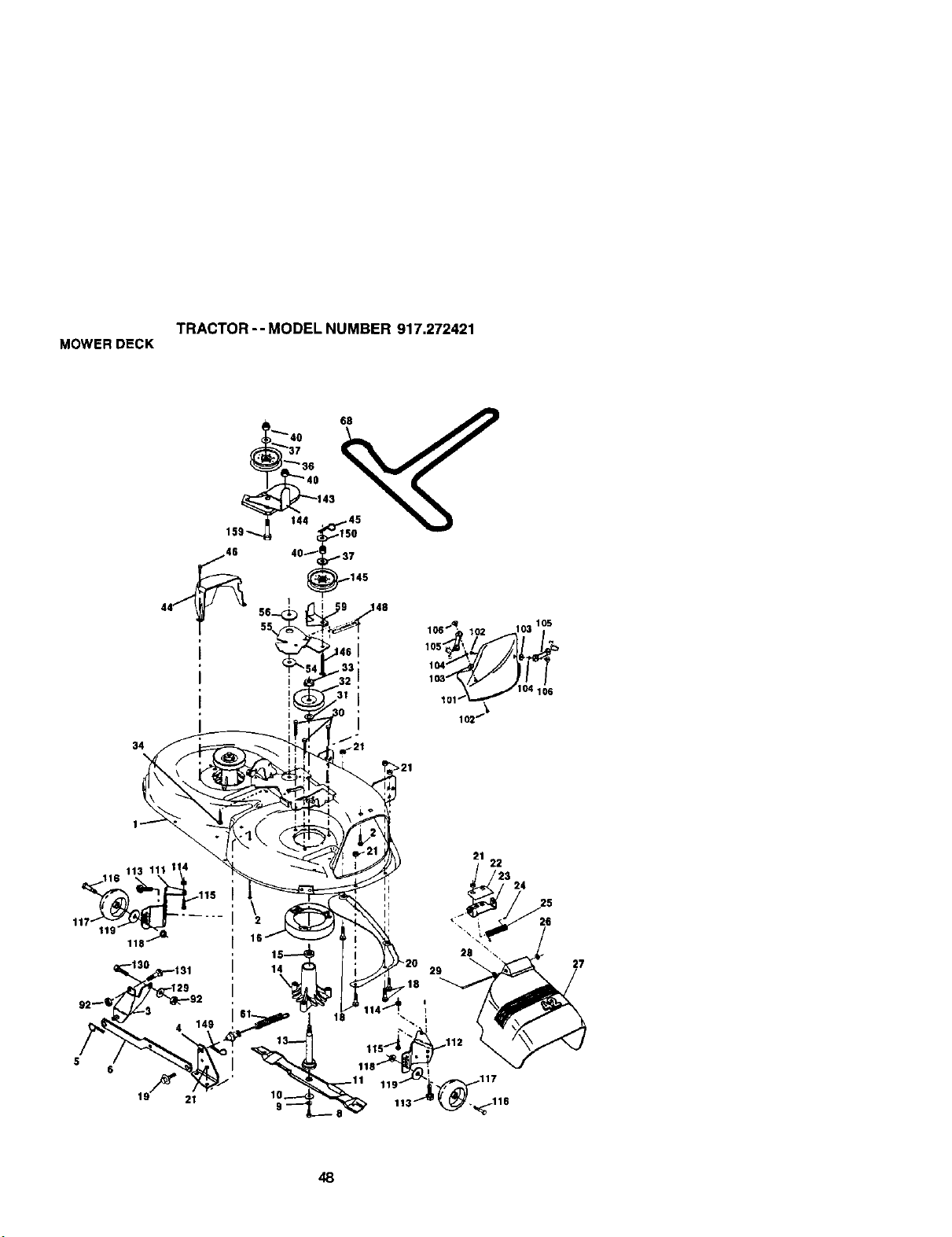
TRACTOR-- MODEL NUMBER 917.272421
MOWERDECK
34
I
_'37
143
144 45
' 1S0
401 37
_145
>21
116 113 111 1 4
5
6
19"_ 21
16
21
22
23 24
48
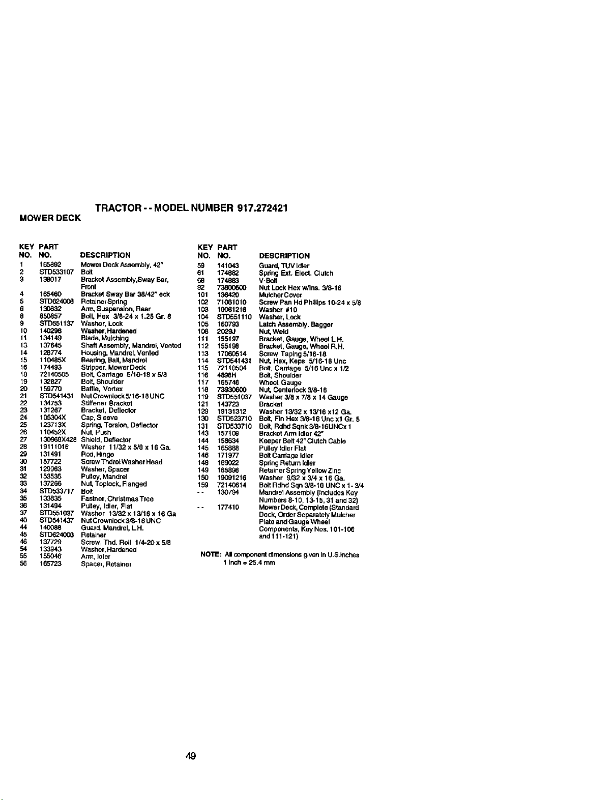
TRACTOR -- MODEL NUMBER 917.272421
MOWERDECK
KEY PART KEY PART
NO. NO. DESCRIPTION NO. NO.
1 165892 Mower Deck Assembly, 42" 59 141043
2 STD533107 Bolt 61 174882
3 138017 Bracket Assembly,Sway Bar, 68 174883
Front _
4 165460 Bracket Sway Bar 38/42" eck 101 136420
5 S]I)_24033 RetaJnerBpdug 1_2 71081010
8 13(_32 Ann, Suspension, Rear 133 19061216
8 853357 Bolt, Hex 3/8-24 x !.25 Gr. 8 104 $7_551110
9 STD561137 Washer, Lock 1335 160733
10 140296 Washer, Hardened 133 90_9J
11 134149 Btade, Mulching 111 155197
13 137645 Shaft Assembly, Mandrel, Vonted 112 155198
14 128774 Housing, Mandrel, Vented 113 17333314
15 110485X Beadng, Ball, Mandrel 114 $1_641431
16 174493 Stripper, Mower Deck lt5 72113304
18 72140505 Bolt,Carriage 3/16-18x5/8 116 4808H
19 132827 Bolt, Shoulder tt7 165746
20 15_7"/0 Barge, Vortex 118 739306(X)
21 STD541431 NutCrownlockS/16-18UNC 119 STD551337
22 134753 Stiffener Bracket 121 143723
23 131267 Bracket, Deflector 129 19131312
24 105304X Cap, Sleeve 130 S]_523710
25 123713X Spdng, Torslon, Deflector 131 S'1_533710
26 110452X Nut, Push 143 1571(_
27 130968X425 ShJeld,DMlector 144 158634
28 19111016 Washer 11/32xS/8x16Ga. 145 165888
29 131491 Red,Hinge 146 171977
30 157722 Screw ThdroLWasher Head 148 1_
31 129963 Washer, Spacer 149 165898
32 153535 Pulley, Mandrel 150 lgO91216
33 137266 Nut, Toplock, Flauged 159 72140614
34 STD533717 Bolt - - 130794
35 133835 Fastner, Chrlctmas Tree
36 131494 Pulley, Idler, Flat - - 177410
37 STD561037 Washer 13/32x13/15xtTGa
40 STD541437 Nut Crownlock 3/8-19 UNC
44 140088 Guard, Mandrel, LH.
45 S]_40G3 Retainer
46 137729 Screw, Thd. ROll 1/4-20 x 5/8
54 133_43 Washer, Hardened
55 155046 Arm, Idler
56 165723 Spacer. Retainer
DESCRIPTION
Guard, TUV Idler
Spdng Ext. Elect. Clutch
V-Bait
Nut LockHex w/Ins. 3/6-16
Mutcher Covor
Screw Pan Hd Philflps 10-24 x 5/8
W_sher #10
Washer, Lock
Latch Assembly. Bagger
Nut, Weld
Bracket, Gauge, Wheel LH.
Bracket, Gauge, Wheel R.H.
Screw Taping 5/18-18
Nut, Hex, Keps 5/16-18 Unc
Bed, Carriage 5/1g Unc x 1/2
Bolt, Shoulder
Wheel, Gauge
Nut, Centedeck 3/6-16
Washer 3/3 x 7/8 x 14 Gauge
Bracket
Washer 13/32 x 13/16 x12 Ga.
Bo_t,Fin Hex 3/8-16 Unc xl Gr. 5
Bolt, Rdhd Sqnk 5/8-t 6UNCx 1
Bracket Arm Idler 42"
Keeper Belt 42" Clutch Cable
Pulley Idler Flat
Bolt Carriage Idler
Spdug Return Idler
Retainer Spring Yellow Zinc
Washer 9/32 x 3/4 x 16 Ga.
Bolt Rdhd Sqn 3/6-18 UNC x 1- 3/4
Mandrel Assembly (includes Key
Numbers 8-10.13-15.31 and 32)
Mower Deck. Complete (Standard
Deck. Order Separately Mulcher
Plate and Gauge Wheel
Components. Key Nos. 101-t06
and111-121)
NO'I1E: AI component dtmer_ors given InU.S.Inches
1 Inch= 25.4 mm
49
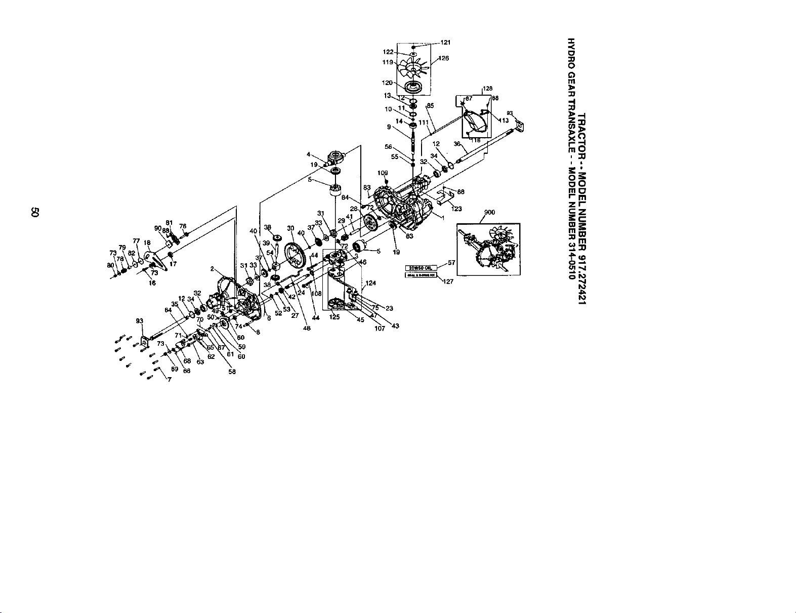
79
73
16
32
71-
107
120_
:>.-I
Z=o
i i
ooo=
r- m
Zl I
o_
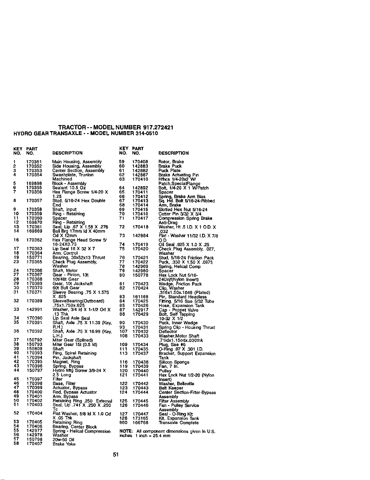
TRACTOR -- MODEL NUMBER 917,272421
HYDROGEARTRANSAXLE- - MODELNUMBER314-0510
KEY PART KEY PART
NO, NO. DESCRIPTION NO. NO, DESCRIPTION
1 170351 Main Housing, Assembly 59 170408 Rotor, Brake
2 170352 Side Housing. Assembly 60 142883 Brake Puck
3 170353 Center Section, Assembly 61 142882 Puck Plate
4 170354 Swashplate. Trunion 62 142667 Brake Antuadng Pin
Machined 63 170410 Ht'ncs 1/4.20x2 Wl
5 169898 Block - Assembly Patch,SpecialFtanmg e
6 170355 Sealant 10.50z 64 142892 Bolt, 1/4-20 X 1 WTPatch
7 170356 Hex Flange Screw 1/4-20 X 65 170411 Spacer
1.25 66 170412 Spdnlg.. Brake Arm B_,s
8 170357 Stud, 5/16-24 Hex Double 67 170413 Sq. Hd. Bolt 5/16-24-Ribbed
End 66 170414 Arm, Brake
9 170358 Shaft, input 69 170415 Slotted Hex Nut 5/16-24
10 170359 Ring - Retaining 70 170416 Cotter Pin 3/32 X 3/4
11 170360 Spacer 71 170417 Compression Spring Brake
12 169870 R=ntg- Retaining Anti-Dra
g
13 170361 Seal, Lip .67 X 1.58 X .276 72 170418 Washer, Ht .5 I.D. X 10.D. X
14 160869 Ball Brg 17mm Id X 40mm .032
Od X 12ram 73 142884 Flat -Washer 11/32 I.D. X 7/6
16 170362 Hex Flange Head Screw 5/ O.D
16-24X0.75 74 170419 Oit Seal .625 X 1.0 X .25
17 170363 Lip Seal 18 X 32 X 7 75 170420 Check Plug Assembly, .027,
18 170364 Ann, Control Washer
19 150771 Bearing, 30x52x13 Thrust 76 170421 Stud, 5/16-24 Friction Pack
23 170365 Check Plug Assembty, 77 170422 Puck, .330 X 1.50 X .0975
Washer 76 142969 Spring, Helioal Comp
24 170366 Shaft, Motor 79 142980 Spacer
27 170367 Gear - Pinion, 131 80 150778 Hex Lock Nut 5/16-
26 170368 10t/46t Gear 24Unjf(Nylon Insert)
29 170369 Gear. 10t Jackshaft 81 170423 Wedge, Friot_on Pack
30 170370 60t Bbll Gear 82 170424 Clip.Washer
31 170371 Sleeve Bearing .75 X 1.575 .316xl.50x.1046 Platad)
X .625 83 161168 Pn, Standard Head ess
32 170389 SleeveBearing(Oetboard) 64 170425 Fitting, 5/16 See 5/32 Tube
.75x1.750x.625 65 170426 Hose. Expansion Tank
33 142991 Washer, 3/4 Id X 1-1/20d X 87 142917 C - Po et Valve
.13 Thk 88 170429 _itoa_,SeffP_aEpoing
34 170390 Lip Seal Axle Seal 16-32 X 1/2
35 170391 Shaft, Axle .75 X 11.39 (Key, 90 170430 Puck. Inner Wedge
R.H.) 93 170431 Spdng Clip - Housing Thrust
36 170392 Shaft, Axle .75 X 16.99 (Key, 107 170432 Deflector
L.H.) 108 170433 Washer.Motor Shaft
37 150792 Miter Gear (Splined) .71idxl.15odx.030thk
38 150793 Miter Gear 15t (0.5 Id) 109 170434 PluJg. See #6
39 150809 Shaft 111 170435 O-Ring .07 X .301 LD.
40 170393 Ring, Spiral Retaining 113 170437 Bracket, Support Expansion
41 170394 Pin, Jackshaft Tank
42 170395 Magnet, Ring 116 170438 Silicon Sponge
43 170396 Spnng, Bypass 119 170439 Fan, 7 In.
44 150797 Hydro Mtg Screw 3/8-24 X 120 170440 Pulle Y
2.5 Long 121 170441 Hex lock Nut 1/2-20 (Nylon
45 170397 Filter Insert)
46 170398 Base. Filter 122 170442 Washer. Belleville
47 170399 Actuator, Bypass 123 170443 Belt Keeper
48 170400 Rod, Bypass Actuator 124 170444 Center Sec5on-Fiiter-Bypa.ss
49 170401 Ann, Bypass Assembly
50 170402 Retaining Ring .250 External 125 170445 Filter Assembly
51 170403 Seal, Lip .741 X .250 X .250 126 170446 Fan- Pulley Service
Tc Assembly
52 170404 Fiat Washer, 5/8 Id X 1,00d 127 170447 Seal - O-Ri_J Kit
X .05 Thk 128 173165 Kit, Expansion Tank
53 170405 Retaining Ring 900 166768 Transaxle Complete
54 170405 Bearing, Center Block
55 142977 Spring - Helical Compression NOTE: All comporleet dimensions given in U,S.
56 142978 Washer inches 1 inch = 26.4 mm
57 150798 20w-50 Oil
58 170407 Brake Yoke
51
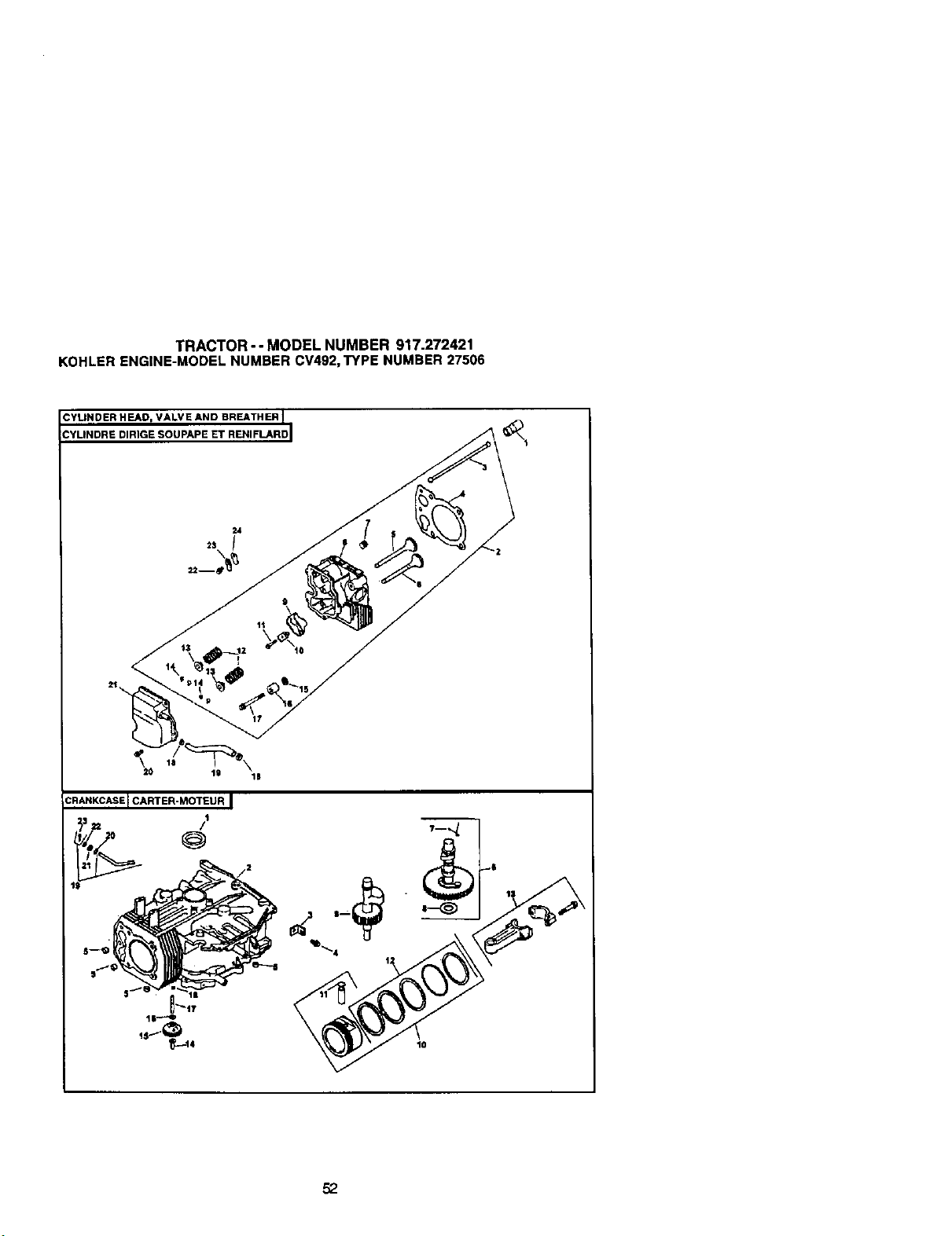
TRACTOR-- MODEL NUMBER 917.272421
KOHLERENGINE-MODELNUMBERCV492,TYPENUMBER27506
CYLINDER HEAD, VALVE AND BREATHER I
CYLINDRE DIRIGE SOUPAPE ET RENIFLARD I
CRARKCASEI CARTER-MOTEUR I
@
11
52
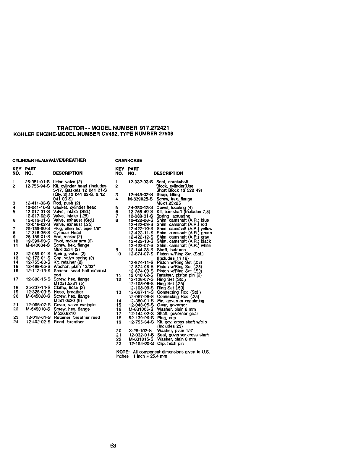
TRACTOR-- MODEL NUMBER 917.272421
KOHLERENGINE-MODELNUMBERCV492,TYPENUMBER27506
CYLINDER HEAD/VALVE/BREATHER
CRANKCASE
KEY PART KEY PART
NO. NO. DESCRIPTION NO. NO. DESCRIPTION
1 25-351-01-S Lifter. valve 42) 1 12-032-03-S
2 12-755-94-S Kit, cylindernead (Includes 2
3-17. Gaskets 12 041 01oS
(Qty. 2),12 041 02-S, & 12 3 12-445-02-S
041 03-S) 4 M-839025-S
3 12-411-O3-S Rod. push 2)
4 12.041-10-S Gasket, cylinder head 5 24o380-13-S
5 12.017-01-S Valve, intake (Std.) 6 12-755-49-S
12-017-02-S Valve, intake (.25) 7 12-08g-31-S
6 12-016-01-S Valve, exhaust (Std.) 8 12-422-0B-S
12-O16-02-S Valve, exhaust (.25) 12-422-09-S
7 25-139-60-S P_u_, alien hd. pipe l/it" 12-422-10-S
8 12-318-36-S Cyhnder Head 12-422-11-S
9 25-186-01-S Arm, rocker (2) 12-422-12-S
10 12-599-03-S Pivot, rocker arm (2) 12-422-13-S
11 M-640034-S Screw, hex. flange 12-422-07-S
M6xl,0x34 (2) 9 12-144-28-S
12 12-089-O1-S Spring, valve (2) 10 12-874-07-S
13 12-173-O1-S Cap, valve spdng (2)
14 12-755-O3-S Kit, re_iner (2) 12-_74-11-S
15 12-468-O5-S Washer. plain 13/32" 12-874-08-S
16 12-112-13-S Spacer, head bolt exhaust 12-874-09-S
port 11 12 018 02-S
17 12-086-1fl-S Screw, hax, flange 12 12-108-07-S
M10x1.5x81 (5) 12-108-08-S
18 25-237-14-S Clamp, hose (2) 12-108-09-S
19 12-326-O3-S Hose, breather 13 12-067-11-S
20 M-645020-S Screw, hex. flange 12-087-06-S
MSxl.0x20 (5) 14 12-3it0_01-S
24 12o096-O7-S Cover, valve w/nipple 15 12-043-05-S
22 M-545010-S Screw. hex. flange 16 M-631005-S
M5x0.8xl0 17 12.144-02-S
23 12-018-01-S Retainer, breather reed 18 52-139-09-S
24 12°402-02-S Reed, breather 19 12-755-64-S
20 X-25-102-S
21 12-032-O1-S
22 M-631015-S
23 12-154-05-S
Seal, crankshaft
Block, cylinderUse
Short Block 12 522 49
Strap, lifting
Screw, hex. flange
Max1.25x25
Dowel locating(4)
Kit, camshaft(Includes 7,8)
Spring, actuating
Sh_n, camshaft(A.R) btue
ShLm,camshaft(A.R.) red
Shim, camshaft(A.R.) yellow
Shim, camshaft(A.R.) green
Shim, camshaft(A.R.) gray
Shim camshaft()A.FLblack
Shim, camshaft (A.R.) wh te
Shaft, balance
Pistonw/Ring Set (Std.)
_ncludes 11,12)
la_n wiring Set (.0B)
Piston w/Ring SOt/51.25
Piston w/Ring Set .5
Retainer, pistonpin (2)
Ring Set (Std.)
Ring Set (.25)
Ring Set (.501
Connecting Rod (Std.)
Connecting Rod .25
Pin, governor reguat ng
Gear, governor
Washer, plain 6 mm
Shaft, governor gear
Plug, cup
Kit, gov. cross shaft w/clip
(Inctudes 23)
Washer, plain 1/4"
Seal, governor cross shaft
Washer, plain 6 mm
Clip, hitch pin
NOTE: All component dimensions given in tJ,S.
inches 1 inch = 25.4 mm
53
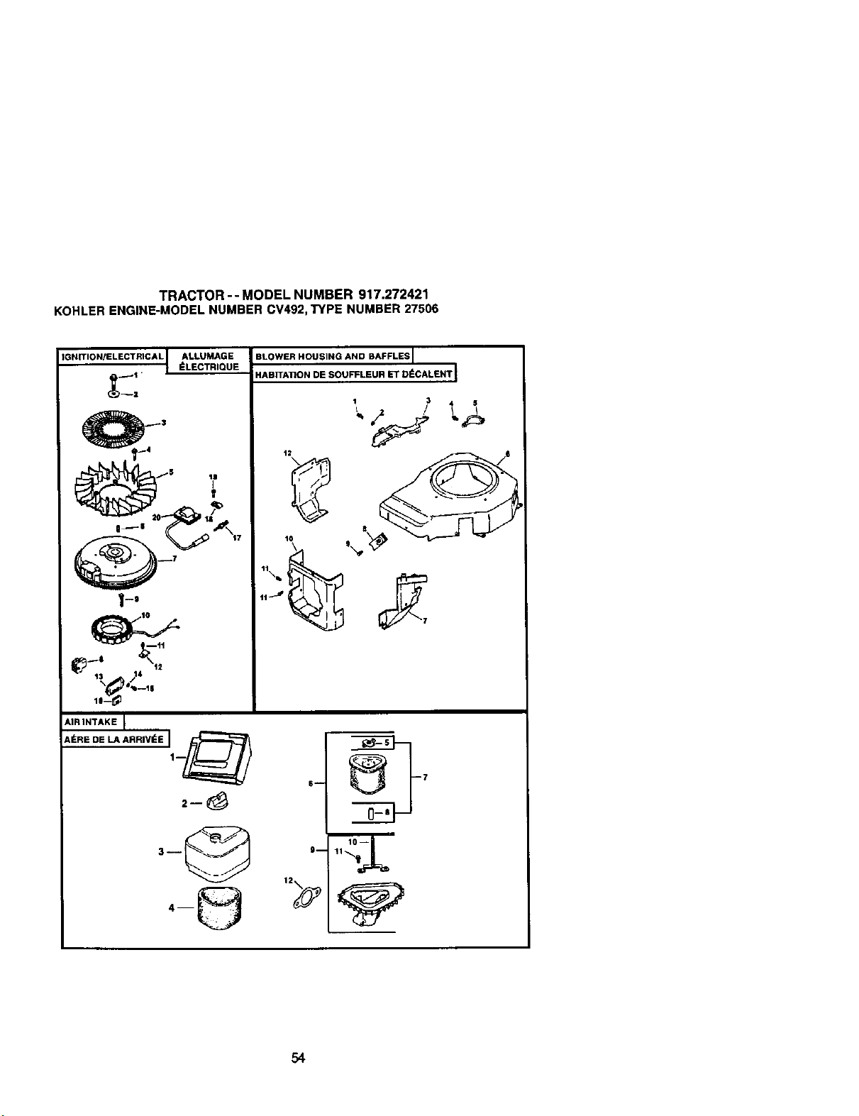
TRACTOR -- MODEL NUMBER 917.272421
KOHLERENGINE-MODELNUMBERCV492,TYPE NUMBER27506
IGNITION/ELECTRICAL] ALLUMAGEI_LECTRIQUE
lJ_ "o--I$
&IRINTAKE I
_I_RE DE LA ARRIVI_E Jl____
BLOWER HOUSING AND BAFFLES I
HABITAT]ON DE SOUFFLEUR ET DI_CALENT _
'\ °_,
54
TRACTOR -- MODEL NUMBER 917.272421
KOHLERENGINE-MODELNUMBERCV492,TYPE NUMBER27506
IGNITION/ELECTRICAL BLOWER HOUSING & BAFFLES
KEY PART KEY PART
NO, NO. DESCRIPTION NO. NO. DESCRIPTION
1 12-086-14-S Screw, hex. flange
MlOx1.5x46
2 12-466-03-S Washer, plain 3/8"
3 24-162-03-S Screen, grass
4 26-086-47-S Bolt, shoulder M6x1.Ox16
5 12-157-O6-S _4a)n
6 X-42-15-S Key
7 12-025-15-S Flywheel
8 12-155-09-S Connector
9 M-548025-S Screw, h_x. cap MSx0.8x25
(2)
10 237878-S Kit, stator
11 M-545020-S Screw, hex. flange
M5xO.Sx2O (2)
12 12-154-06-S Clip, cable (2)
13 41-403-09-S Reguletc_', rectifier - 15 amp
14 X-22-11 -S Washer, lock 1/4"
15 M-639016-S Screw, hex. flange
M6xl.0x16 (2)
16 236602-S Connector
17 12-132-02-S Spark Plug
18 X-726-1-S Clip, cable (2)
19 M-545010-S Screw, hex. flange
MSxO.8xlO 2)
20 12-584-04-S Modue, gnton
NOT ILLUSTRATED
12-176-44-S HaJ'ness, win
nq
24-518-12-S Lead, black 6" - 12 gauge-
nsu etnd grip barrel eyelet
terminals)
12-516-35-S Lead, white 36" - 16 gauge
- fully insulated push on tab
and uninsulated socket
termir_ls)
X-25-5-S Washer, plain 5/16" (attach
ground lead and this
washer to lift strap screw)
1 M-545010-S Screw, hex. flange
MSxO.8xl0 46)
2 24-468-10-S Washer, plain 1/4"
3 12-146-07-S Plate, blower housing
4 M-550010-S Screw, hex. flange
M5xO.8xl0
5 24-O96-05-S Cover, pinion
6 12-027-76-S Houain_l, blower.
7 12-063-18-S Baffle, retake side
8 25-154-02-S Clip, mounting (3)
9 12-086-37-S Screw, ca tive washer
Mgx0.Sx2_(3)
10 12-O63-20-S Baffle, cyE_der head
11 M-645016-S Screw, hex. flange
M6x1.0x16 2)
12 12-063-19-S Baffe, cy nder
NOT ILLUSTRATED
M-541056-S Nut, hex. flange M5xO.8
AIR INTAKE/FILTRATION
KEY PART
NO. NO. DESCRIPTION
1 12-281-01-S Duct,air
2 25-341-03-S Knob, air cleaner cover
3 12-096-24-S Cover,air cleaner
4 12-063-12-S Precleaner, element
5 12-100-08-S Wing Nut
6 12-083-10-S K_, air cleaner element
(includes5. 7, 8)
7 12-743-12-S Filter,element (Includes5, 8)
8 12-632-11-S Seal 1-7/16"
9 12-094-07-S Base, air cleaner (Includes
11, 12)
10 12-072-04-S Stud, mounting plate
M6x1.0x75
11 12-O86-01-S Screw, #10 Hi-Lo thread
formlag (2)
13 12-041-02-S Gasket, air cleaner
NOT ILLUSTRATED
12-113-53-S Decal, air cleaner
NOTE: All component dimensionsgiven in U,S.
inches 1 inch= 25,4 mm
55
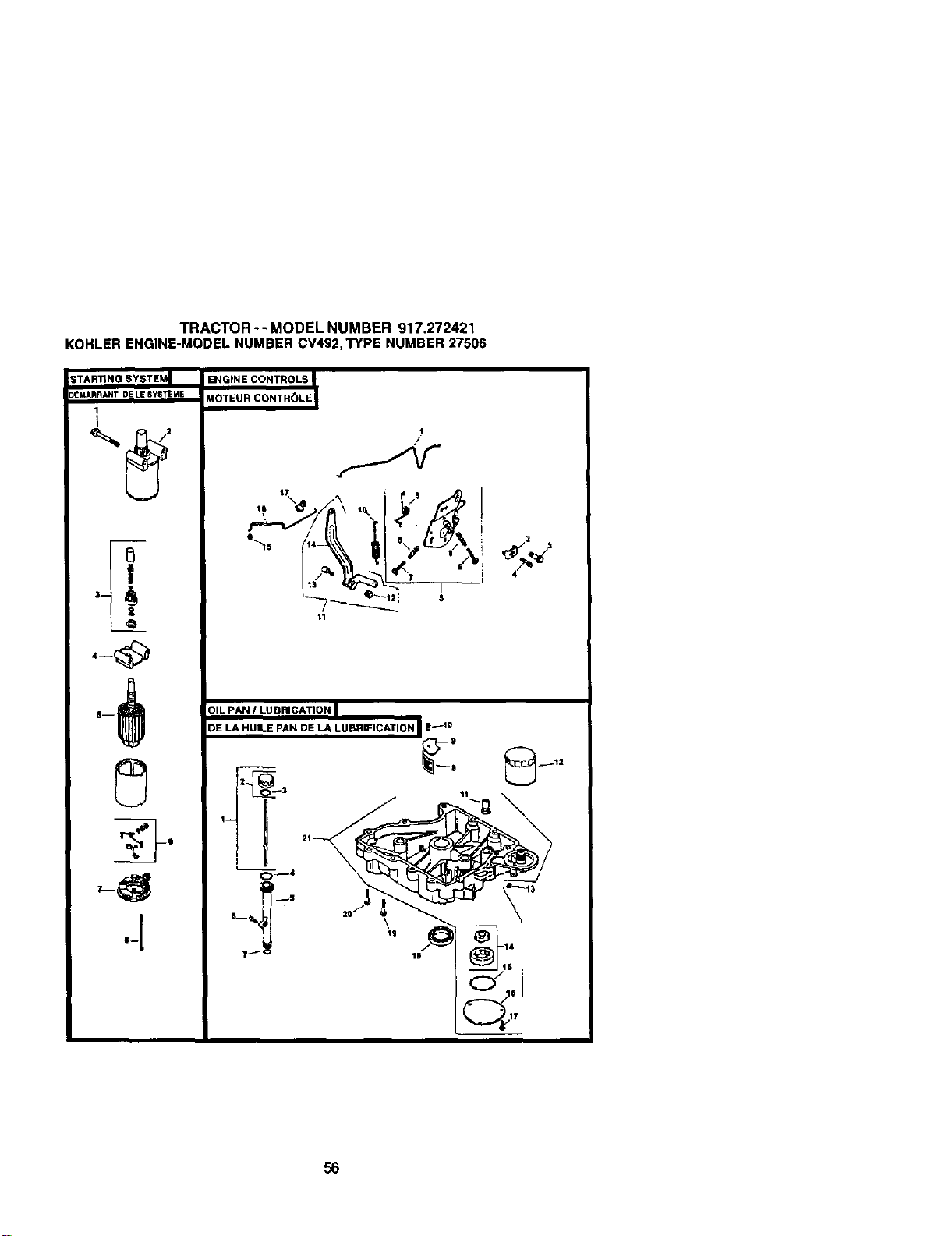
TRACTOR-- MODEL NUMBER 917.272421
KOHLERENGINE-MODELNUMBERCV492,TYPE NUMBER27506
3TARTING SYSTEM I ENGINE CONTROLS
_MARRANT DE LE SYST_ME MOTEUR CONTR_)LE
1
I
Z
/
I
,_ ¢ \ '\ I
°',, _,4_ ,B o,._t_t\:,
tl
OIL PAN I LUBRICATION |
DE LA HUII.E PAN DE LA LUBRIFICATION I'-'°
(_/lg
56
TRACTOR -- MODEL NUMBER 917.272421
KOHLERENGINE-MODELNUMBERCV492,TYPE NUMBER27506
STARTING SY_'rEM
ENGtNF. COt4TROLS
KEY PART KEY pART
NO. NO. DESCRIPTION NO. NO. DESCRIPTION
1 M-833070-S Screw hex. f_ar_3e "_ 12-07g-11-S
M8x1.25x70 (2) 2 12-237_01-S
2 25-098-07-S Starter assembly (Includes 3 24-086-43-S
3-8) 4 M-664020-S
3 12-755-54-S Kit, ddve end
4 12-227-1_*S Cap, drive end 5 12-536-10-S
5 12-170-05-S Armature M-443025-S
6 12-221-01-S Kit. brush & sprLng 6
7 12-227-13-S C_p, commutator end 7 M-443020-S
8 12-211-01-S Bolt, hex. flange 8 12-089-11-B
1/4-20x4-5{6 (2) 9 12-08g-23-B
10 12-089-24-S
OIL PAN/LUBRICATION 11 12-755-83-S
KEY PART
NO. NO. DESCRIPTION
1 12-038-01-S Dipstick assembly (Includes
2-3)
2 25-755-13-S Kit, oil 511cap (Includes 3)
3 12-153-03-S O-Ring, oil flUCap
4 12-153-02-S O-Ring, uJpperoil fill tube
5 12-123-g4-sTube,oU_i
6 M-645025-S Screw, hex. flange
M6xl .Ox25
7 12-153-01-S O-Ring, lower oil fill tube
8 25-162-07-S Screen, oil pickup
9 12-O96-03-S Cover, oil pickup screen
10 M-545016-S Screw, hex. flange
M5x0.8x16
11 25-462-09-S Valve, oil pressure relief
12 52-050-02-S Fitter. oil
13 25-139-57-S Plug, sq. hd solid 3/8"
14 12-393-01-S Pump, oil
15 12-153-06-S O-Ring, oil pump cover
16 12-096-34-S Cover, oil pump
17 M-545016-S Screw, hex. flange
M5x0.6x16 (3)
18 12-032-03-S Sea_, oil (RT.O. end)
19 24-086-16-B Screw, hex. flan e
M8xl.25x45 (11_
20 24-086-17-B Scm_, hex. fl_e
Mgx1,25x45
21 12-199-56-S Assembly, Pan, oil (Incl,
11,14-17)
12 12-100"07-S
13 52-211-04-B
14 12-090-28-S
15 25-158"08-S
16 12-079-10-S
17 25-156-11-S
Liw_ge, choke
Clamp, cable
Screw. hex. flange
Screw, lobed socket
M6XI.Ox20(2)
Control speed assembly
(Includes 6-9)
Screw, pan head M4xO.7X25
Screw, pan head M4xO.7x20
Spdng, choke (2)
Spdng, choke return
Spring governor
Kit, governor ever (Includes
12-14)
Nut, hex flange 1/4-20
Bott, 1/4-20x1"
Lever. govemor
Bushing,throttle linkage
Linkage. throttle
Bushing,throttle linkage
NOTE: All component dimensions given in U.S.
inches 1 inch = 25.4 mm
57
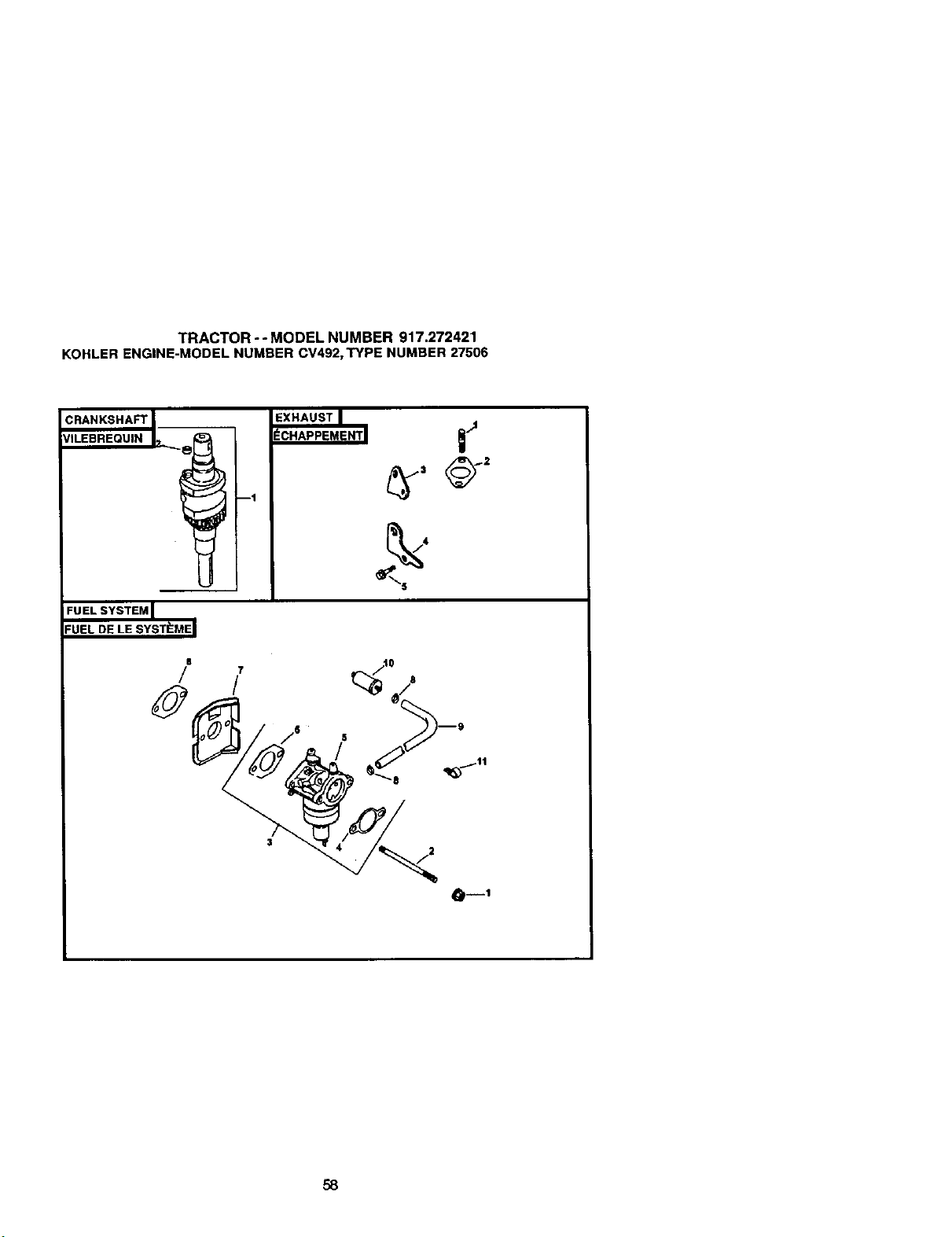
TRACTOR -- MODEL NUMBER 917.272421
KOHLERENGINE-MODELNUMBERCV492,TYPE NUMBER27506
CRANKSHAFT
VILEBREQUIN
--1
FUEL SYSTEM
FUEL DE LE SYSTt_MEI
s 10
a--I
58
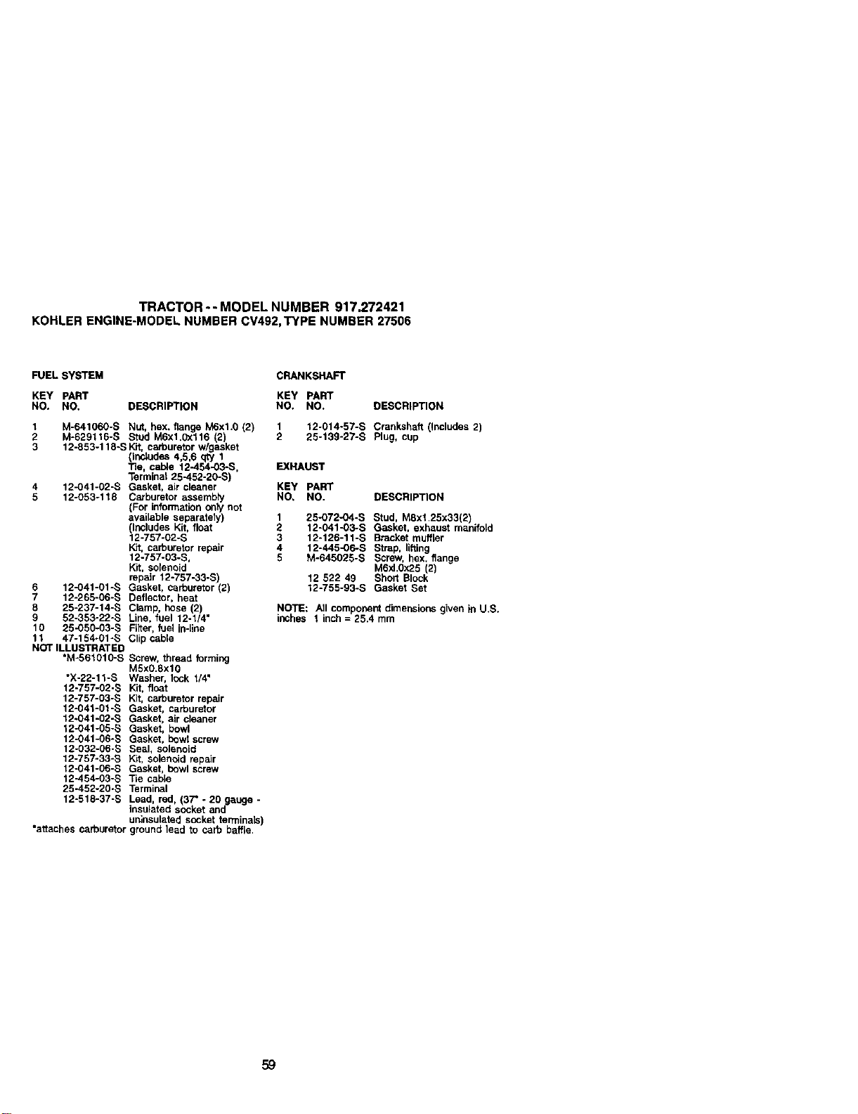
TRACTOR -- MODEL NUMBER 917.272421
KOHLERENGINE-MODELNUMBERCV492,TYPE NUMBER27506
FUEL SYSTEM CRANKSHAFT
KEY PART KEY PART
NO. NO. DESCRIPTION NO. NO. DESCRIPTION
1 M-641060-S Nut, hex. flange M6xl.0 (2) 1 12-014-57-S Crankshaft (Includes 2)
2 M-629116-S Stud M6xl.0x116 (2) 2 25-139-27-S Plug, cup
3 12-853-118-SKit, carburetor w/gasket
(Inbludes 4,5,6 q_J 1
Tie, cable 12-454-03-S, EXHAUST
Terminal 25-452-20-S)
4 12-O41-02--_ Gasket, air cleaner KEY PART
5 12-053-118 Carburetor assembty NO, NO. DESCRIPTION
(For information only not
available separately 1 25-072-04-S Stud, M8xl 25x33(2)
(Includes Kit, float 2 12-041-03-S Gasket, exhaust manifold
12-757-02-S 3 12-126-11-S Bracket muffler
Kit, carburetor repair 4 12-445-06-S Strap, lifting
12-757-03-S, 5 M-645025-S Screw, hex. flange
Kit, solenbld M6xl.0x25 (2)
repair 12-757-33-S) 12 522 49 Short Block
6 12-041-01-S Gasket, carburetor (2) 12-755-93-S Gasket Set
7 12-265-06-S Deflector, heat
8 25-237-14-S Clamp, hose (2) NOTE: All component dimensions given in U.S.
9 52-353-22-S Line, fuel 12-1/4" inches 1 inch = 25.4 mm
10 25-050-03-S Filter, fuel in-line
11 47-154-01-S Clip cable
NOT ILLUSTRATED
*M-561010-S Screw, thread forming
M5x0.8xl0
*X-22-11-S Washer, Icck 1/4"
12-757-02-S Kit, float
12-757-03-S Kit, carburetor repair
12KI41-01-S Gasket, carburetor
12-041-02-S Gasket, air cleaner
12-041-05-S Gasket, bowl
12-041-06-S Gasket, bowt screw
12-032-06-S Seal, solenoid
12-757-33-S Kit, solenoid repair
12-041-06-S Gasket, bowl screw
12-454-03-S Tie cable
25-452-20-S Terminal
12-518-37-S Lead, red, (37" - 20 gauge -
insulated socket and
uniosulated socket terminals)
"attachescarburetorground lead to caYobaffle
59

SERVICE NOTES
6O

SERVICE NOTES
61

SERVICE NOTES
62
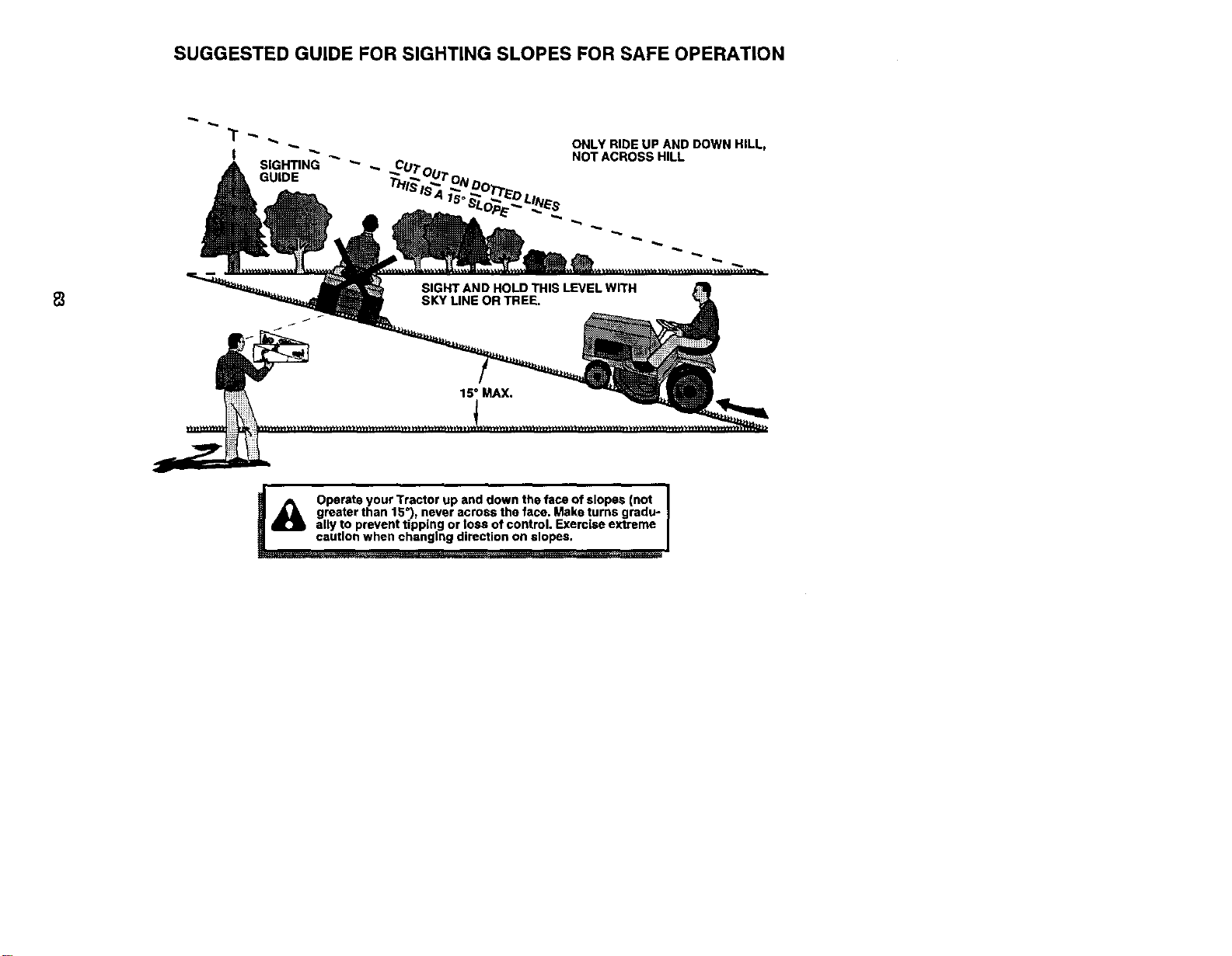
SUGGESTED GUIDE FOR SIGHTING SLOPES FOR SAFE OPERATION
ONLY RIDE UP AND DOWN HILL,
NOT ACROSS HILL
A OperateyourTractorupanddownthefaceofslopes(not J
greater than 15 ), never across the face. Make turns gradu- J
ally to prevent tipping or toss of control. Exerclss extreme
caution when changing direction on slopes.

For repairofmajorbrandappliancesin yourown home...
nomatterwhomadeit,no matterwhosold
Forrepairofcarry-inproductslikevacuums,lawnequipment,and
electronics,callforthenearestSearsPartsand RepairCenter.
1-800--488-1222 An,/,_T_day_ nigN(U.SAmfy)
For the replacement parts, accessories and owner's manuals
that you need todo-R-yourself,call Sears PattsDIrect _]
1-800-366-PART 6a.m.- 11p.m.,7daysaweek
(__00-366-7278) (U.S.A.only)
www.seam._
To purchaseor inquireabouta SearsServiceAgreement
orSeatsMaintenanceAgreement:
1-800-827-6655 (u.s._.) 1-800-361-6665 (Canada)
7 a.m.- 5 p.m.,CST, lv_r_- Sat. 9 a.m.- 8 p.m,EST,M- F, 4 pJn.Sat.
o Sears,P,oebud_mdCo.
HorneCent ® J
® Registered Trademark / "tuTrademark / st=Service Mark of Seam, Roebuck and Co.
® Mama Registrada / TMMama de F&bdca / sMMama de See_icio de Sears, Roebuck and Co.
McMarque de commerce / MeMarque d6posde de Sears, Roebuck and Co.
179146 03.21.01 RH Printed in U.S.A.


