
Loading ...
Loading ...
Loading ...
Safety Rules and Instructions: Extension Cords
Double insulated tools have 2-wire cords and can be used with 2-wire or 3-wire extension cords.
Only round jacketed extension cords should be used, and we recommend that they be listed by
Underwriters Laboratories (U.L.) (C.S.A. in Canada). If the extension will be used outside, the
cord must be suitable for outdoor use. Any cord marked as outdoor can also be used for indoor
work. An extension cord must have adequate wire size (AWG or American Wire Gauge) for safety,
and to prevent loss of power and overheating. The smaller the gauge number of the wire, the
greater the capacity of the cable, that is 16 gauge has more capacity than 18 gauge. When using
more than one extension to make up the total length, be sure each individual extension contains
at least the minimum wire size. Before using an extension cord, inspect it for loose or exposed
wires, damaged insulation, and defective fittings. Make any needed repairs or replace the cord if
necessary.
To determine the
minimum wire size
required, refer to
the chart:
4
Safety Rules and Instructions: Polarized Plug
To reduce the risk of electric shock, this equipment has a polarized plug
(one blade is wider than the other). This equipment must be used with a
suitable polarized 2 wire or 3 wire extension cord. Polarized connections
will fit together only one way. Make sure that the receptacle end of the
extension cord has large and small blade slot widths. If the plug does not
fit fully into the extension cord, reverse the plug. If it still does not fit, obtain
a suitable extension cord. If the extension cord does not fit fully into the
outlet, contact a qualified electrician to install the proper outlet. Do not
change the tool plug or extension cord in any way.
The label on your tool may include the following symbols:
V ...............volts A ....................amperes
Hz .............hertz W ....................watts
min ............minutes
or AC .........alternating current
or DC...direct current
n
o ...................no load speed
..............
double insulated
.................... earthing terminal
............safety alert symbol .../min or rpm...revolutions or
reciprocation per minute
............Read instruction manual before use
................Use proper respiratory protection
................Use proper eye protection
................Use proper hearing protection
ASSEMBLY
NOTE: Ensure the blower is switched off and disconnected from the
power supply before attaching or removing the blower tubes. The
tube assembly must be assembled to the housing before use.
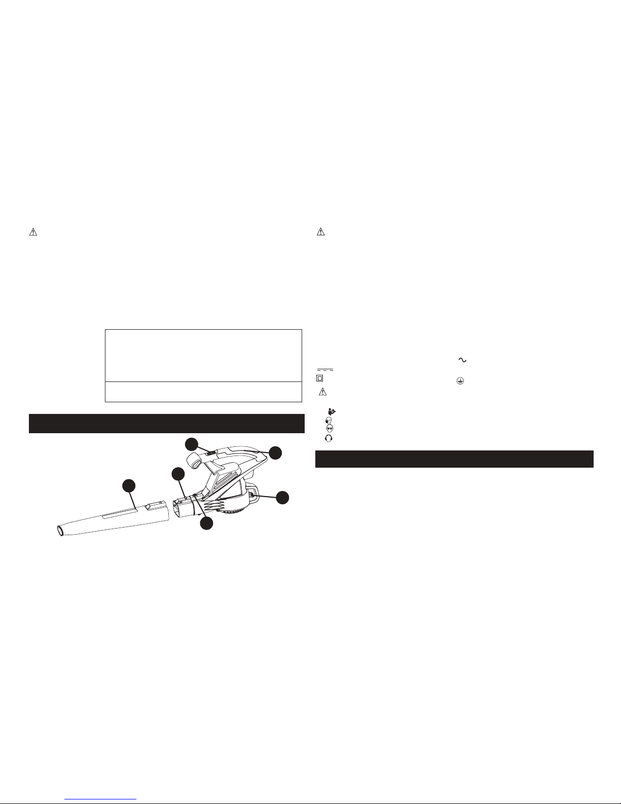
TUBE ASSEMBLY (FIGURE A)
•
To attach the blower tube (4) to the blower, line up the tube with the
blower housing as shown in figure A. Push the tube into the blower
housing until the lock lever (3) engages the lock hole in the blower tube.
• To rem
ove the tube depress the lock button and slide the tube off
the blower housing.
FUNCTIONAL DESCRIPTION
1. On / Off Switch
2. Blower Tube Release Button
3. Lock Lever
4. Blower Tube
5. Cord Retention Hook
6. Power Head Handle
5
1
2
4
3
Minimum Gauge for Cord Sets
Volts Total Length of Cord in Feet
120V 0-25 26-50 51-100 101-150
Ampere Rating
More Not more American Wire Gauge
Than Than
0 - 6 18 16 16 14
6 - 10 18 16 14 12
6
Downloaded from www.ManualsFile.com manuals search engine
Loading ...
Loading ...
Loading ...