Electronic Astronomic
7-Day Time Switch
Time Switch
• Input Voltage: 120/208/240/277 VAC, 60 Hz
• Power Consumption: 6.0 W Max.
• Contact Conguration: SPST (ET8015C), DPST (ET8215C). See
wiring diagrams on next page.
Switch Ratings—ET8015C, ET8215C (per pole)
• 30 A Inductive/Resistive, 120/240 VAC, 60 Hz
• 20 A Magnetic Ballast, 120-277 VAC, 60 Hz
• 1 A Electronic Ballast 120-277 VAC, 60 Hz
• 20 A Resistive, 28 VDC
• 5 A Tungsten: 120/240 VAC, 60 Hz
• 1 HP, 120 VAC, 60 Hz
• 2 HP, 240 VAC, 60 Hz
Set Points (Events)—Each load output of the Time Switch can support up
to 14 timed ON and 14 timed OFF events per day as well as Astro ON
and Astro OFF events.
Installation and User Instructions
MODEL ET8000 Series
The Intermatic ET8000 Series Electronic Astronomic 7-Day Time
Switch automatically switches loads to a preset weekly schedule with
to-the-minute accuracy.
• The astronomic feature provides an automatically adjusted sunset
ON and sunrise OFF to eliminate the need for separate photo control
devices.
• The independent 7-day programming provides complete exibility for
applications where load switching differs each day of the week.
• Astronomic programming can be combined with independent
programming to provide a sunset ON and timed OFF program.
Use the ET8000 series as an ON/OFF timer in applications requiring
7-day astronomic load control such as lighting, air conditioning systems,
pumps, etc. Each load output of the Time Switch can support up to 14
timed ON and 14 timed OFF events per day as well as Astro ON and Astro
OFF events. The program can be overridden by pushing the ON/OFF load
override button(s).
The ET8000 Series Time Switch is designed to directly switch tungsten
or ballast loads up to its rating, and inductive or resistive loads up to
30A at 120, 208, 240, or 277 VAC.
Specifications
With Battery
Carryover
Description
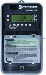
Front View
Rear View
B
A
WARNING
Risk of Fire or Electric Shock
• Disconnect power at the circuit breaker(s) or disconnect switch(es) before installing or servicing.
• Installation and/or wiring must be in accordance with national and local electrical code
requirements.
• For outdoor locations or wet locations (rain-tight), conduit hubs that comply with requirements of
the UL514B (standard for fitting conduit and outlet boxes) are to be used.
• This enclosure does not provide grounding between conduit connections. When metallic conduit
is used, you must also install grounding type bushings and jumper wire.
• For plastic enclosures, bonding between conduit connections is not automatic and must be
provided as part of the installation.
• Use #18 - #10 AWG wires, rated at least 75°C - COPPER conductors ONLY.
• If the power disconnect point is out of sight, lock it in the OFF position and tag it to prevent
unexpected application power.
• Make sure there is no wire insulation under the terminal plate on the time switch connector.
Firmly tighten terminal screws.
• Do not remove insulator that is covering terminals.
• KEEP DOOR CLOSED AT ALL TIMES when not servicing.
NOTICE
• Do NOT touch circuit board components, contact can create a static discharge, which can
damage the microprocessor.
Installation Instructions
Slide down
to remove
battery case
Snap out catch
Tilt top forward
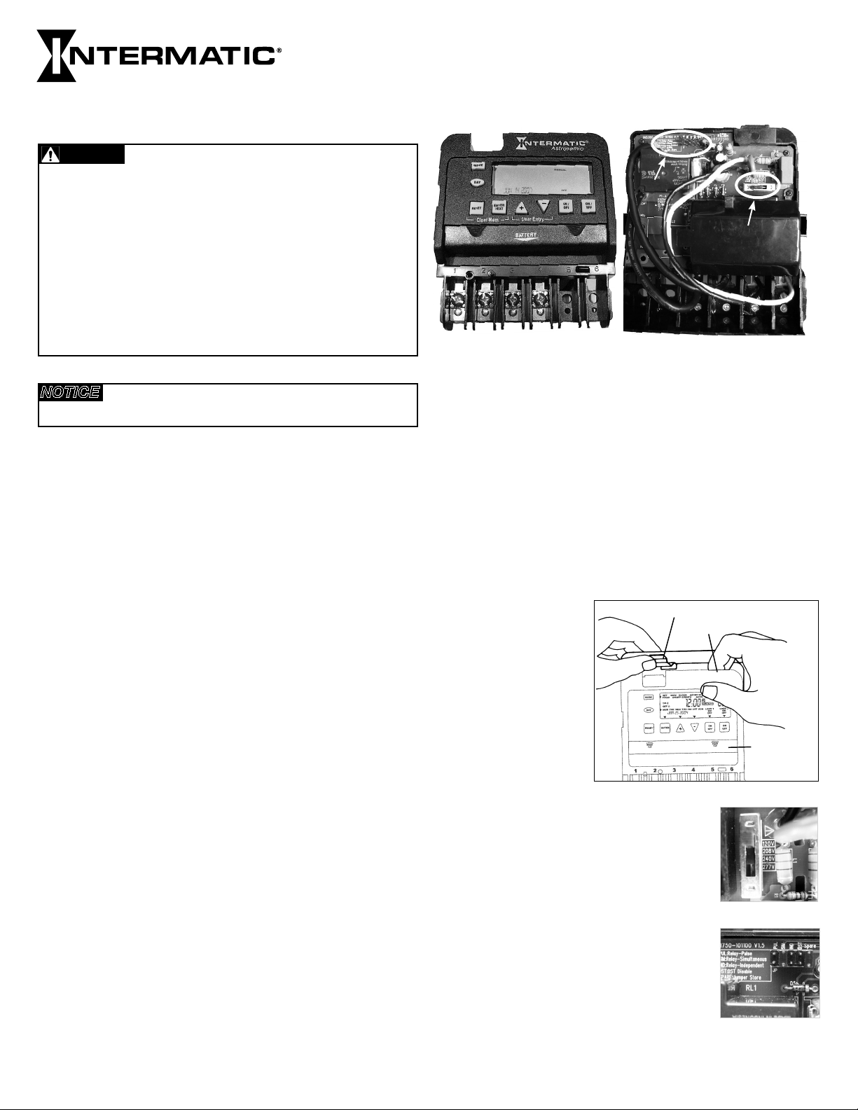
2. Set voltage selector for desired input voltage. The timer is
shipped with voltage set for 277 VAC. To
operate at 120, 208 or 240 VAC, move the
selector switch to the desired setting as
marked on the circuit board. See location A in
Rear View above and detail at the right.
3. The timer is shipped with DST (Daylight Saving
Time) enabled. To disable DST, insert a jumper
at location marked DST. See location B in Rear
View above and detail at the right.
4. ET8215C ONLY—Decide whether you want to
control multiple loads simultaneously (SIM),
independently (IND), or with a 2-second pulse
(PUL) (e.g., for use with mechanically held
contactors or bell ringing applications), and
make sure the jumper is positioned accordingly.
See location B in Rear View above and detail at the right.
(The unit is shipped with the loads set for IND.)
1. Remove the mecha-
nism from the case by
depressing the catch
at the top of the case
and pulling out, as
shown.
Battery-Powered Clock Operation—3 years minimum (uses 2 AAA industrial
grade alkaline batteries, supplied)
Minimum ON or OFF time—1 minute
Maximum ON or OFF time—6 days, 23 hours, 59 minutes
Shipping Weight—2.5 lb. (1.1 kg)
Enclosures—ET8xx5C – TYPE 1 indoor metal enclosure
Knockouts—Combination 1/2-3/4 inch size, 1 on back and each side,
2 on bottom
Wire Size—AWG #18 through #10
1
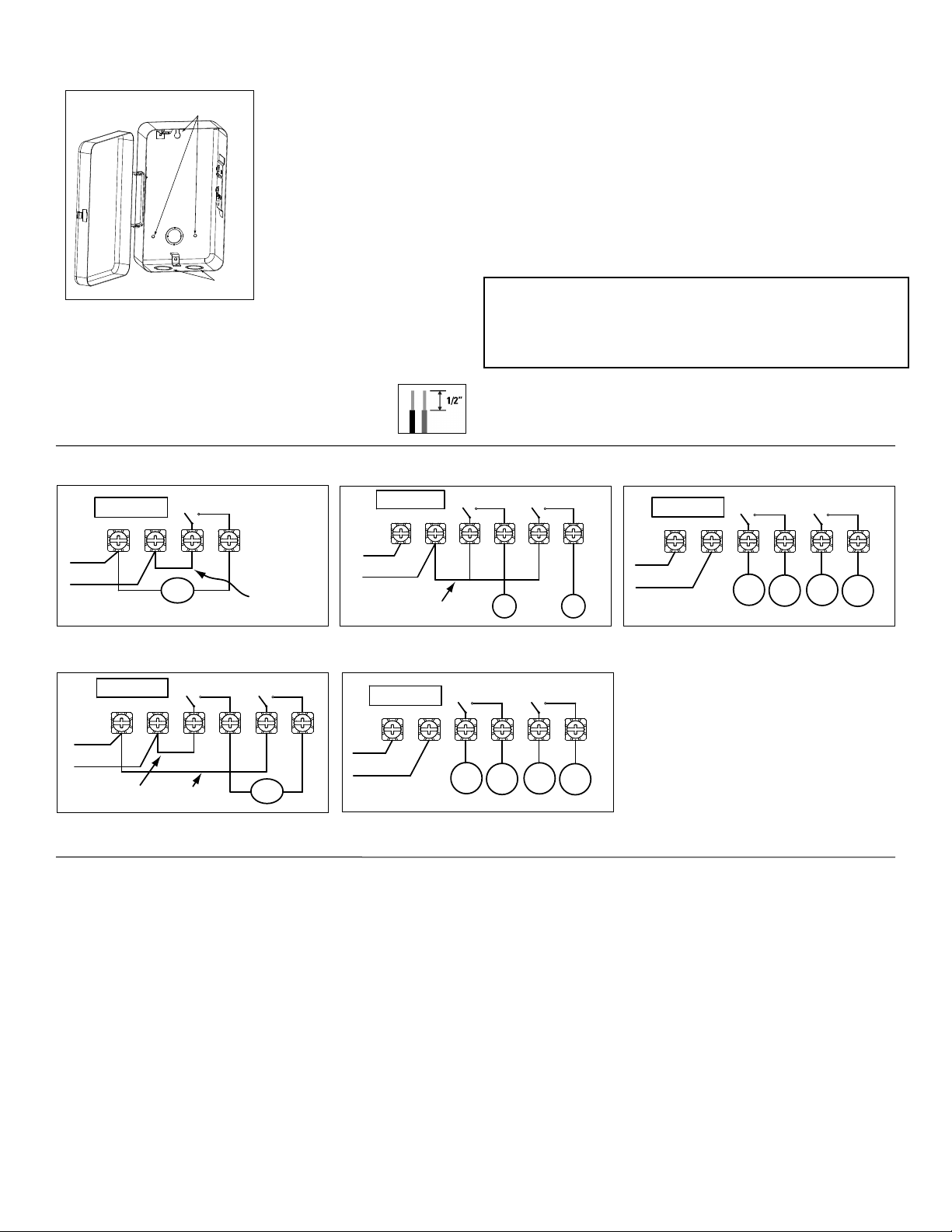
Knockouts
Mounting holes
1
Neutral
120VAC
Input
Hot
2 3 4
Timer Power
Load
Install jumper
only if timer input
and load voltage
are the same
ET8015 configured for SPST, 120 VAC load
1
Line 2
240VAC Input
Line 1
2 3 4 5 6
Line 1
Line 2
Install jumper only if timer input
and load voltage are the same
Timer Power
Load
ET8215 configured for 240 VAC DPST load
with jumper set to SIM
1
L2/N
120/208/240/277
VAC Input
Line 1
2 3 4 5 6
ON
Install jumper only if timer input
and load voltage are the same
OFF
Timer Power
ET8215 configured for pulse SPST load
with jumper set to PUL
1
L2/N
120/208/240/277
VAC Input
Line 1
2 3 4 5 6
Load
1
Timer Power
Load
2
Line
1
Line
2
ET8215 configured for 2 SPST loads
with jumper set to IND
1
L2/N
120/208/240/277
VAC Input
Line 1
2 3 4 5 6
Load
1
Timer Power
Load
2
Line
1
Line
2
ET8215 configured for DPST loads
with jumper set to SIM
Programming Overview
By pressing the MODE button, the Time Switch will cycle through the
menus necessary for programming the current time, date, astro zone,
astro events, and timed events.
The basic procedure is to use the MODE button to move from one
menu to the next (e.g., DATE, TIME, etc.), the + or – buttons for the
rst part of a setting (e.g., MONTH), the ENTER button to move to the
next part of the setting (e.g., YEAR), then MODE to exit and move to the
next menu. To skip a menu, press MODE to move ahead.
If you make a mistake, press the MODE button repeatedly to cycle
back around to the error, then make the correct entry.
NOTE: DATE and TIME must be set before you can access any other
programming menus.
Setting Date
1. Press the MODE button repeatedly until the words SET and DATE
appear in the upper area of the display.
Setting Time
1. If necessary, press the MODE button repeatedly until the words
SET and CLOCK appear in the upper area of the display.
2. Press the + or – buttons to enter the current time.
NOTE: To go from AM to PM, keep pressing the + or – buttons to
cycle through the day. You can hold the + or – buttons down for
3 seconds to make the time scroll quickly.
3. Press the MODE button to exit and advance to setting Astro Zone.
2. Press the + or – buttons to enter the current Month.
3. Press the ENTER button when the Month is correct to save the
setting. The screen advances to current Date.
4. Again press the + or – buttons to enter the current Date, followed
by the ENTER button.
5. Repeat to set the correct Year.
6. Press the MODE button to exit and advance to setting the time.
Wiring Diagrams
6. Replace the mechanism in the enclosure.
7. Lift the left side of the plastic insulator off the retaining post and
pivot it up and away to expose the terminal strip.
8. Strip the supply and load wires to 1/2”. Use #18 - #10
AWG wires, rated at least 75°C - COPPER conductors ONLY
5. Mount the enclosure in the desired location using the 3
mounting holes provided.
9. Insert the wire ends under the proper terminal plates (see wiring
diagrams elsewhere on this page) and tighten the screws rmly.
10. Connect ground wire to grounding terminal at bottom of enclosure.
11. Replace the plastic insulator on the retaining post.
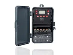
12. Remove the battery case by sliding it down as shown by the
arrows, then install 2 AAA alkaline batteries. Make sure the
batteries are pointing in the direction shown.
13. Verify that the display is ON to make sure the batteries are OK.
If the display shows scrambled information, press the RESET
button to clear it up.
14. Apply power to the Time Switch.
The Time Switch is now ready for programming.
Position at eye level if possible, providing space to the left of
the enclosure for the cover to swing open fully, as shown.
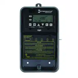
IMPORTANT: Press and hold the ENTER button, then press the
RESET button. The screen will ash 12:00 AM and MON, and timer
status is Manual Mode.
NOTE: You must reset the time switch using this procedure
whenever you change the jumpers.
2

An ASTRO event will let you set Sunset ON and Sunup OFF events.
1. If necessary, press the MODE button repeatedly until the words
SET, ASTRO, and ON/OFF EVENTS appear in the upper area of
the display.
2. Press the ENTER button if necessary to display ON @.
3. Make sure you know which days you want the Event to be active.
- If you want the Event to occur every day of the week, press the
DAY button to display SUNSET and all days.
- If you want the Event to occur for a different combination of
days, press the DAY button again as necessary to cycle through
the days or combination of days you want.
Setting SUNSET ON/SUNUP OFF Events
Setting Astro Zone
Astro Zone is how far north or south the location is, to adjust for
differences in sunrise and sunset for better accuracy in turning lights
on and off at dawn and dusk.
1. If necessary, press the
MODE button repeatedly
until the words SET and
ASTRO ZONE appear in
the upper area of the
display.
2. Press the + or – buttons
to display the Zone that
includes the location.
Use the map at the right
as a reference.
3. Press the MODE button to exit and advance to setting exact Astro
times.
Fig. 8
South
North
Center
North
Center
South
Setting Exact Astro Times
When you choose an Astro Zone, the Time Switch uses an approximate
time for sunup and sunset, adjusting automatically as the seasons
change (earlier sunset in winter, etc.) You can set exact sunup and
sunset times, which are available in the newspaper or on the Internet.
For multi-circuit time switch ET8215C, you can set multiple sunup and
sunset times—useful, for example, in environments involving lighting
with different warm-up times.
1. If necessary, press the MODE button repeatedly until the words SET
and SUNUP appear in the upper area of the display. The display
also shows the default sunup time for the date and zone.
2. Press the + or – buttons to adjust the sunup time. You can offset
the time up to 120 minutes in either direction.
3. Press the MODE button:
- If a multi-circuit time switch, SUNUP and LOAD 2 appear on
the display.
a. Press the + or – buttons to set the exact Sunup time for
Load 2.
b. Press the MODE button to advance to Sunset for Load 1.
- If a single-circuit time switch,
The words SET and SUNSET appear on the display, along with the
default sunset time for the date and zone.
4. Press the + or – buttons to adjust the sunset time. You can offset
the time up to 2 hours (120 minutes) in either direction.
5. Press the MODE button:
- If a multi-circuit time switch, SUNSET and LOAD 2 appear on
the display.
a. Press the + or – buttons to set the exact Sunset time for
Load 2.
b. Press the MODE button.
- If a single-circuit time switch,
The time switch exits and advances to setting events.
NOTE: To remove an individual day, press the DAY button
until the day is blinking, then press the – button.
4. When you have set the event correctly, press the ENTER button to
set the next Astro event, which is for Sunup OFF. The words SET,
ASTRO, ON/OFF EVENTS, and OFF @ display.
5. Repeat from Step 3 above to set the event for OFF instead of ON.
6. Press the MODE button to exit and advance to setting xed time
events.
An ASTRO event will let you set Sunset ON and Sunup OFF events.
When the circuits of multi-circuit time switch ET8215C set to be
independent of each other, you can set sunup and sunset times for
either or both circuits.
1. Verify that the two circuits are independent. Refer to Step 4 in
Installation Instructions on page 1.
2. If necessary, press the MODE button repeatedly until the words SET,
ASTRO, ON/OFF EVENTS, and LOAD 1 appear in the display.
3. Press the ENTER button if necessary to display ON @.
4. Make sure you know which days you want the Sunset ON event
to be active.
- If you want the Event to occur every day of the week, press the
DAY button to display SUNSET and all days.
- If you want the Event to occur for a different combination of
days, press the DAY button again as necessary to cycle through
the days or combination of days you want.
NOTE: To remove an individual day, press the DAY button
until the day is blinking, then press the – button.
5. When you have set the event correctly, press the ENTER button to set
the next Astro event, which is Sunset ON for Load 2. The words SET,
ASTRO, ON/OFF EVENTS, LOAD 2, and ON @ appear in the display.
6. Repeat from Step 4 above to set the event for ON.
7. Press the ENTER button to set Sunup OFF for Load 1. The words
SET, ASTRO, ON/OFF EVENTS, LOAD 1 and OFF @ appear in
the display.
8. Repeat from Step 4 above to set the Event for OFF instead of ON.
9. Press the ENTER button to set Sunrise OFF for Load 2. The words SET,
ASTRO, ON/OFF EVENTS, LOAD 2, and OFF @ display.
10. Repeat from Step 4 above to set the event for OFF instead of ON.
11. Press the MODE button to exit and advance to setting xed time
events.
Setting SUNSET ON/SUNUP OFF Events
on Multi-Circuit Time Switches (ET8215C)
1. If necessary, press the MODE button repeatedly until the words
SET, FIXED, ON/OFF EVENT and EVENT 01 appear on the
display.
2. If necessary, press the ENTER button to display ON @ or OFF @
(depending on what you want to set).
3. Press the DAY button to display 12:00 am and all days of the
week.
4. Press the + or – buttons to enter the time you want to set.
NOTE: To go from AM to PM, keep pressing the + or – buttons
to cycle through the day. You can hold the + or – buttons down
for 3 seconds to make the time scroll quickly.
5. If you want the Event to occur for a combination of days rather
than every day (e.g., weekends only, weekdays only, or individual
days), press the DAY button again as necessary to cycle through
the individual days or combination of days you want.
NOTE: To choose a combination not shown during cycling
(e.g., Tuesday and Thursday), you must create an individual
event for each of the days you want.
Setting Fixed Timed Events
3

Setting Sunset ON / Fixed Time OFF
1. If necessary, press the MODE button repeatedly until the words
SET, ASTRO, and ON/OFF EVENTS appear in the upper area of
the display.
2. Press the ENTER button if necessary to display ON @.
3. Make sure you know which days you want the Sunset ON event
to be active.
- If you want the Event to turn ON every day of the week, press
the DAY button to display SUNSET and all days.
- If you want the Event to turn ON for a different combination of
days, press the DAY button again as necessary to cycle through
the days or combination of days you want.
To remove an individual day, press the DAY button until the
day is blinking, then press the – button.
4. Press the MODE button as necessary to display SET, FIXED and
ON/OFF EVENT.
5. Press the ENTER button as necessary to display OFF @ and
EVENT 02.
6. Press the DAY button to display 12:00 am and all days of the
week.
7. Press the + or – buttons to enter the time you want to set.
To go from AM to PM, keep pressing the + or – buttons to cycle
through the day. You can hold the + or – buttons down for 3
seconds to make the time scroll quickly.
8. If you want the Event to occur for a combination of days rather
than every day (e.g., weekends only, weekdays only, or individual
days), press the DAY button again as necessary to cycle through
the individual days or combination of days you want.
NOTE: To choose a combination not shown during cycling
(e.g., Tuesday and Thursday), you must create an individual
event for each of the days you want.
6. ET8215C ONLY—For a multi-circuit device with loads set
independently, you can choose the load you want the event to
control. The default setting is for both loads, as you can see on
the display. Press the ON/OFF button under a load to remove the
load from the event.
7. When you have set the event correctly, you have two choices:
- Press the ENTER button to set the next xed time event (up to
28 events).
- Press the MODE button to exit.
Press the MODE button repeatedly to select the desired operating
mode on the display. There are 2 options:
• AUTO—where the Time Switch follows the events you have
programmed, turning the circuits ON and OFF at the time(s) set.
NOTE: You can override programmed events and force the
Time Switch ON or OFF by pressing the ON/OFF button.
• MANUAL—where any events set are disabled and the Time Switch
controls all circuits through the ON/OFF button.
NOTE: You can review or edit any programmed events at any time by
pressing the MODE button repeatedly to return to the appropriate menu,
then following programming instruction provided on this sheet.
Operating the Time Switch
Use this procedure to clear the settings programmed for an event.
1. If necessary, press the MODE button repeatedly until the words
SET, FIXED, and ON/OFF EVENTS are shown on the display.
2. Press the ENTER button as necessary to cycle through events that
have been set until you see the event you want to delete.
3. Press the + or – buttons AT THE SAME TIME to display --:-- --.
4. Press the MODE button to exit.
OPTIONAL – Deleting (Clearing) an Event
158--01992
• Batteries can be easily replaced without removing the Time Switch
mechanism or eld wiring.
• Press in and downward (in the direction of the arrows) on the
battery cover.
• It is recommended to replace the batteries every 2-3 years with 2
AAA industrial grade alkaline cells as part of normal maintenance
on the Time Switch.
• Be sure to observe battery polarity markings when installing
batteries.
• No other battery maintenance is required.
Battery Maintenance
9. ET8215 ONLY—For a multi-circuit device with loads set
independently, you can choose the load you want the event to
control. The default setting is for both loads, as you can see on
the display. Press the ON/OFF button under a load to remove the
load from the event.
10. When you have set the event correctly, you have two choices:
- Press the ENTER button to set the next xed time event (up to
28 events).
- Press the MODE button to exit.
INTERMATIC INCORPORATED, SPRING GROVE, ILLINOIS 60081-9698
LIMITED ONE-YEAR WARRANTY
If within the warranty period specified, this product fails due to a defect in material or workmanship, Intermatic Incorporated will repair or replace it, at its sole option, free of charge.
This warranty is extended to the original household purchaser only and is not transferable. This warranty does not apply to: (a) damage to units caused by accident, dropping or abuse
in handling, acts of God or any negligent use; (b) units which have been subject to unauthorized repair, opened, taken apart or otherwise modified; (c) units not used in accordance
with instructions; (d) damages exceeding the cost of the product; (e) sealed lamps and/or lamp bulbs, LED’s and batteries; (f) the finish on any portion of the product, such as surface
and/or weathering, as this is considered normal wear and tear; (g) transit damage, initial installation costs, removal costs, or reinstallation costs.
INTERMATIC INCORPORATED WILL NOT BE LIABLE FOR INCIDENTAL OR CONSEQUENTIAL DAMAGES. SOME STATES DO NOT ALLOW THE EXCLUSION OR LIMITATION OF
INCIDENTAL OR CONSEQUENTIAL DAMAGES, SO THE ABOVE LIMITATION OR EXCLUSION MAY NOT APPLY TO YOU. THIS WARRANTY IS IN LIEU OF ALL OTHER EXPRESS OR
IMPLIED WARRANTIES. ALL IMPLIED WARRANTIES, INCLUDING THE WARRANTY OF MERCHANTABILITY AND THE WARRANTY OF FITNESS FOR A PARTICULAR PURPOSE, ARE
HEREBY MODIFIED TO EXIST ONLY AS CONTAINED IN THIS LIMITED WARRANTY, AND SHALL BE OF THE SAME DURATION AS THE WARRANTY PERIOD STATED ABOVE. SOME
STATES DO NOT ALLOW LIMITATIONS ON THE DURATION OF AN IMPLIED WARRANTY, SO THE ABOVE LIMITATION MAY NOT APPLY TO YOU.
This warranty service is available by either (a) returning the product to the dealer from whom the unit was purchased or (b) completing a warranty claim online at www.intermatic.com. This warranty is
made by: Intermatic Incorporated, Customer Service 7777 Winn Rd., Spring Grove, Illinois 60081-9698. For warranty service go to: http://www.Intermatic.com or call 815-675-7000.
Experience in the eld has shown that is the most commonly used
setting for the Time Switch. These instructions cover the entire
procedure.
4