
IMPORTANT SAFETY INSTRUCTIONS
Carefully read the following important information regarding
installation safety and maintenance.
Keep these instructions for future reference.
.""/
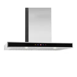
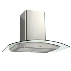
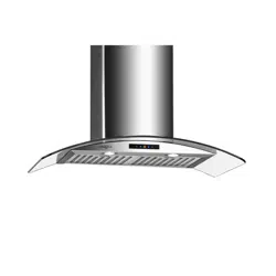
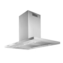
RANGE HOOD
USER INSTRUCTIONS
MODEL:
AERO ISLAND IV 36”
IMPORTANT SAFETY NOTICE
READ ALL INSTRUCTIONS BEFORE INSTALLING AND OPERATING THIS APPLIANCE
● The installation in this manual is intended for qualified installers, service technicians or persons
with similar qualified background. Installation and electrical wiring must be done by qualified
professionals and in accordance with all applicable codes and standards, including fire-rated
construction.
● Range hood may have very sharp edges; please wear protective gloves if it is necessary to
remove any parts for installing, cleaning or servicing.
● Activating any switch ON before completing installation may cause ignition or an explosion.
● Due to the size and weight of this range hood, two people installation is recommended.
To reduce the risk of fire, electric shock, or injury to persons:
● For general ventilating use only. DO NOT use to exhaust hazardous or explosive materials
and vapors.
● The combustion air flow needed for safe operation of fuel-burning equipment may be affected
by this unit’s operation. Follow the heating equipment manufacturer’s guideline and safety
standards such as those published by the National Fire Protection Association (NFPA), and the
American Society of Heating, Refrigeration and Air Conditioning Engineers (ASHRAE), and
other local code authorities.
● Before servicing or cleaning unit, switch power OFF at service panel and lock service panel to
prevent power from being switched ON accidentally.
● Clean grease laden surfaces frequently. To optimize performance and to disperse air properly,
make sure to vent air outside. DO NOT vent exhaust into spaces between walls, crawl spaces,
ceiling, attics or garages.
● Ducted fans MUST always be vented to the outdoors.
● This unit MUST be grounded and use only metal ductwork.
● Sufficient air is needed for proper combustion and exhausting of gases through the duct to
prevent back drafting.
● When cutting or drilling into wall or ceiling, be careful not to damage electrical wiring or other
hidden utilities.
● All electrical wiring must be properly installed, insulated and grounded.
● Old duct work should be cleaned or replaced if necessary to avoid the possibility of a grease fire.
● Check all joints on duct work to ensure proper connection and all joints should be properly
taped.
● Use this unit only in the manner intended by the manufacturer. If you have questions, contact
the vendor.
2
IMPORTANT SAFETY NOTICE
READ ALL INSTRUCTIONS BEFORE INSTALLING AND OPERATING THIS APPLIANCE
To reduce the risk of stove top grease fire:
●
●
●
●
●
●
●
Note: * if included with your model
To reduce the risk of injury to persons in the event of a stove top grease fire:
●
● L PICK UP A P
P MAL AWAY
ACUA CALL PA
● WA
● LY
Y C
Y
To reduce the risk of injury to persons in the event of a gas leaks:
●
●
●
Y We
3
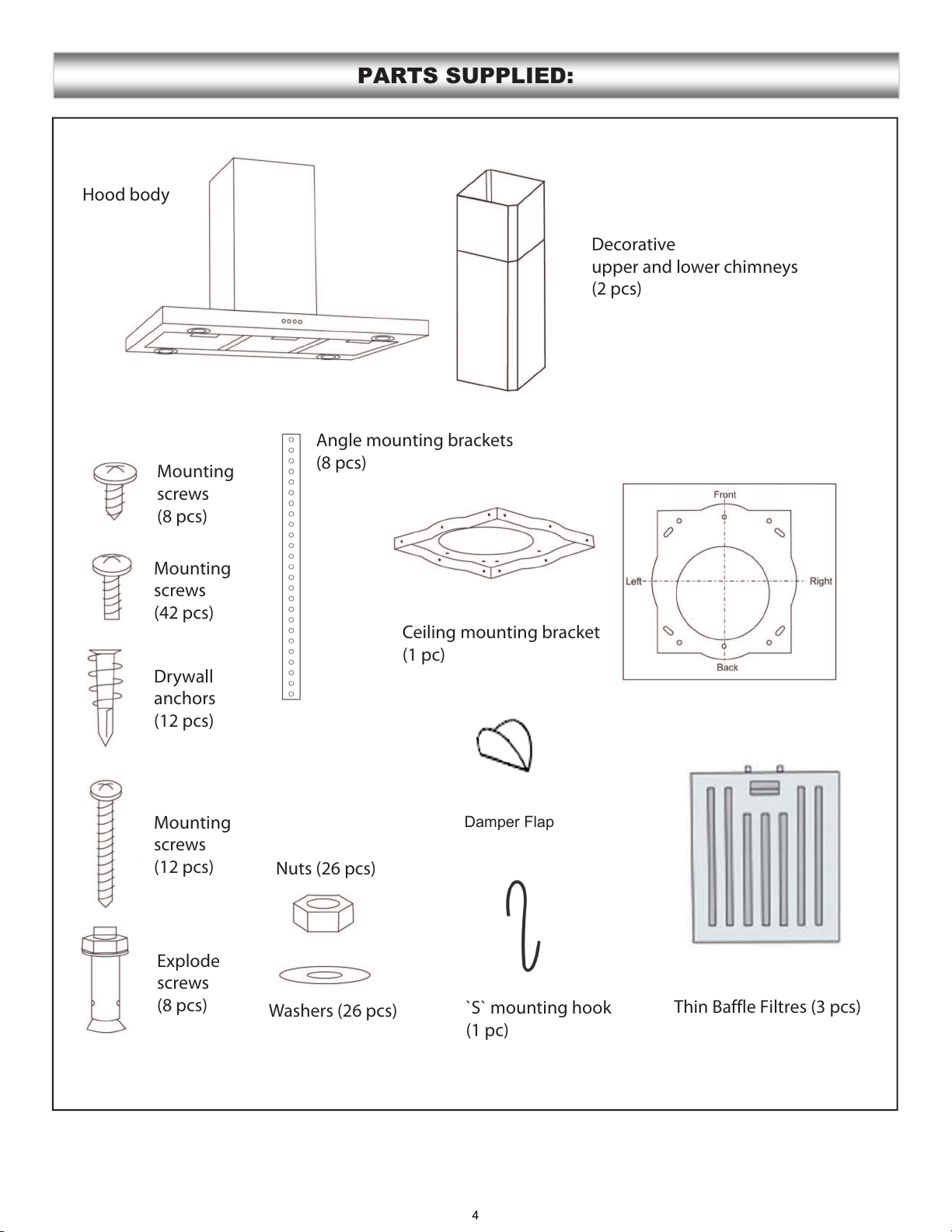
PARTS SUPPLIED:
Decorative
upper and lower chimneys
(2 pcs)
Hood body
Angle mounting brackets
(8 pcs)
Ceiling mounting bracket
(1 pc)
5IJO#BGGMF'JMUSFTQDT
`S` mounting hook
(1 pc)
Washers (26 pcs)
Nuts (26 pcs)
Explode
screws
(8 pcs)
Mounting
screws
(12 pcs)
Drywall
anchors
(12 pcs)
Mounting
screws
(42 pcs)
Mounting
screws
(8 pcs)
4
Damper Flap
• Vent system must terminate to the outside
(Roof or side wall).
• DO NOT terminate the vent system in an attic
or other enclosed area.
• DO NOT use 4” (10.2 cm) laundry-type wall
caps.
• Use metal/aluminum vent only. Rigid metal/
aluminum vent is recommended.
• DO NOT use plastic vent.
• Always keep the duct clean to ensure proper
airflow.
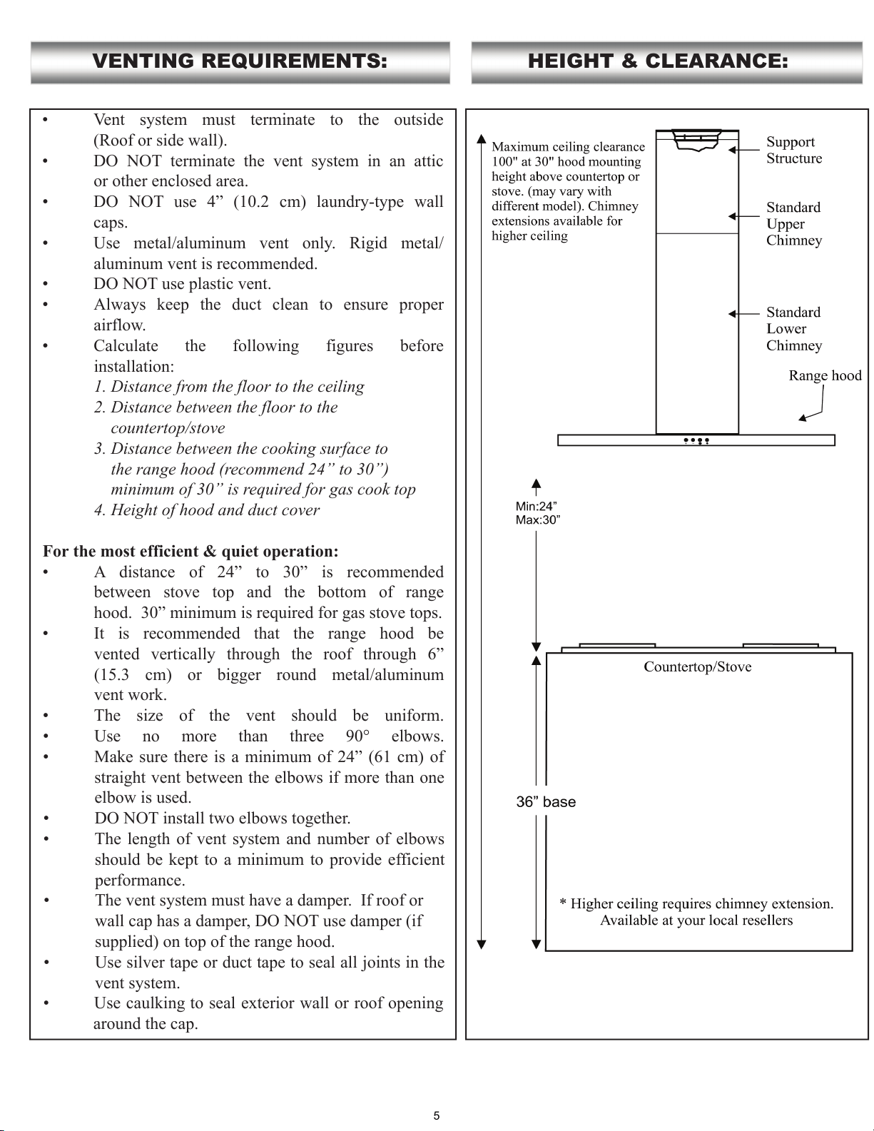
• Calculate the following figures before
installation:
1. Distance from the floor to the ceiling
2. Distance between the floor to the
countertop/stove
3. Distance between the cooking surface to
the range hood (recommend 24” to 30”)
minimum of 30” is required for gas cook top
4. Height of hood and duct cover
For the most efficient & quiet operation:
• A distance of 24” to 30” is recommended
between stove top and the bottom of range
hood. 30” minimum is required for gas stove tops.
• It is recommended that the range hood be
vented vertically through the roof through 6”
(15.3 cm) or bigger round metal/aluminum
vent work.
• The size of the vent should be uniform.
• Use no more than three 90° elbows.
• Make sure there is a minimum of 24” (61 cm) of
straight vent between the elbows if more than one
elbow is used.
• DO NOT install two elbows together.
• The length of vent system and number of elbows
should be kept to a minimum to provide efficient
performance.
• The vent system must have a damper. If roof or
wall cap has a damper, DO NOT use damper (if
supplied) on top of the range hood.
• Use silver tape or duct tape to seal all joints in the
vent system.
• Use caulking to seal exterior wall or roof opening
around the cap.
VENTING REQUIREMENTS: HEIGHT & CLEARANCE:
5
IMPORTANT:
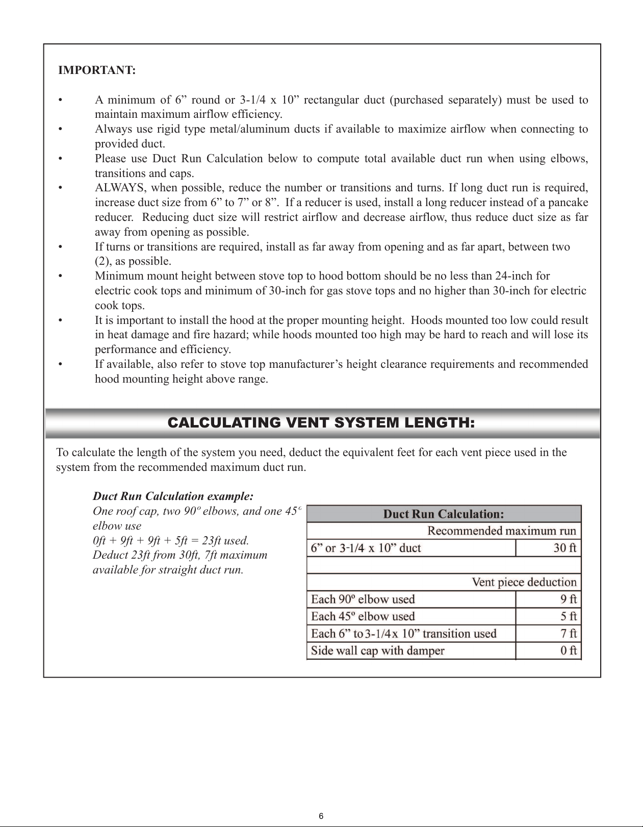
CALCULATING VENT SYSTEM LENGTH:
Duct Run Calculation example:
One roof cap, two 90º elbows, and one 45º
elbow use
0ft + 9ft + 9ft + 5ft = 23ft used.
Deduct 23ft from 30ft, 7ft maximum
available for straight duct run.
-
6
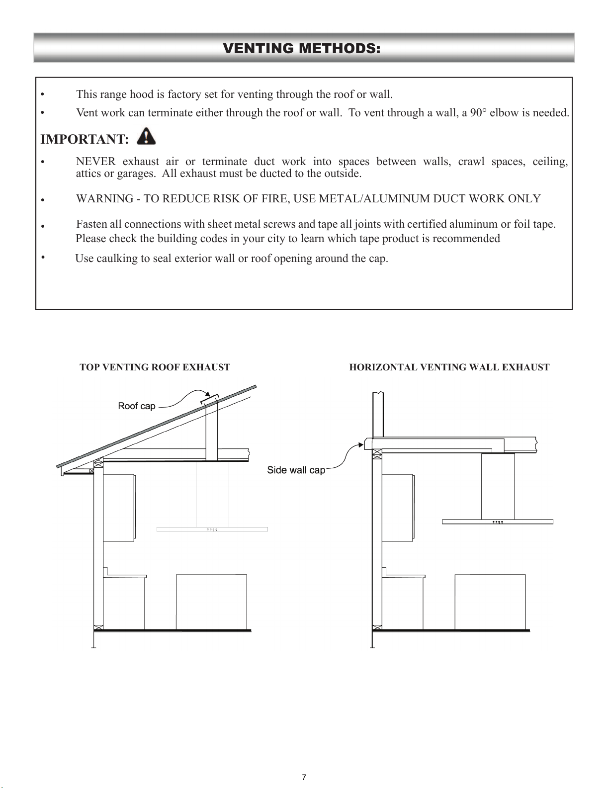
• This range hood is factory set for venting through the roof or wall.
• Vent work can terminate either through the roof or wall. To vent through a wall, a 90° elbow is needed.
IMPORTANT:
NEVER exhaust air or terminate duct work into spaces between walls, crawl spaces, ceiling,
attics or garages. All exhaust must be ducted to the outside.
•
WARNING - TO REDUCE RISK OF FIRE, USE METAL/ALUMINUM DUCT WORK ONLY
•
Fasten all connections with sheet metal screws and tape all joints with certified aluminum or foil tape.
Please check the building codes in your city to learn which tape product is recommended
•
Use caulking to seal exterior wall or roof opening around the cap.
VENTING METHODS:
•
HORIZONTAL VENTING WALL EXHAUSTTOP VENTING ROOF EXHAUST
7
IMPORTANT:
Observe all governing codes and ordinances.
It is the customer’s responsibility to contact a qualified electrical installer.
If codes permit and a separate ground wire is used, it is recommended that a qualified electrician determine
that the ground path is adequate.
A 120-Volt, 60 Hz, AC-only, fused electrical supply is required on a separate 15-amp circuit, fused on both
sides of the line.
DO NOT ground to a gas pipe.
Check with a qualified electrician if you are not sure that the range hood is properly grounded.
DO NOT have a fuse in the neutral or ground circuit.
IMPORTANT: Save this Installation Guide for electrical inspector’s use.
The range hood must be connected with copper wire/plug only.
The range hood should be connected directly to the fused disconnect (or circuit breaker) box through
flexible armored or non-metallic sheathed copper cable. UL/CSA listed strain relief must be provided at
each end of the power supply cable.
ELECTRICAL REQUIREMENTS:
8
Advanced Preparations:
• Be familiar with the controls of the range hood by reading through Range Hood Operations, Page 13.
• Place the range hood on a flat, stable surface. Connect the range hood to a designated standard outlet
(120-Volt, 60Hz, AC only) and turn on the range hood. Verify all operations of the range hood by
referring to Range Hood Operations.
• Place all supplied parts and required hardware on a flat, stable surface and verify the existence of all
supplied parts listed on Page 4.
Preparations:
NOTE: To avoid damage to your hood, prevent debris from entering the vent opening.
• Determine and mark the center line on the ceiling or wall where the range hood will be installed.
Make sure there is proper clearance within the ceiling or wall for exhaust vent.
• Due to the weight and size of this unit, please make sure that the support system or framework being
used is stable and secure in the ceiling or wall.
• Put a thick, protective covering over counter top, cook top or range to protect from damage or dirt.
Remove any hazardous objects around the area when installing.
CAUTION
If moving the cooking range is necessary to install the hood, turn OFF the power on an electric range at
the main electrical box. SHUT OFF THE GAS BEFORE MOVING A GAS RANGE
PREPARATIONS:
9
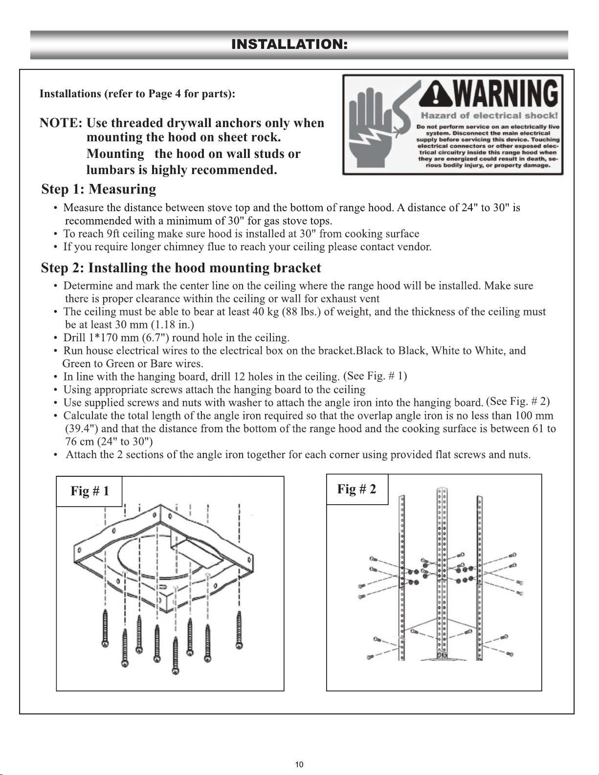
Installations (refer to Page 4 for parts):
INSTALLATION:
(See Fig. #1)
(See Fig. #2)
Fig #
Fig #
10
INSTALLATION CONTINUE:
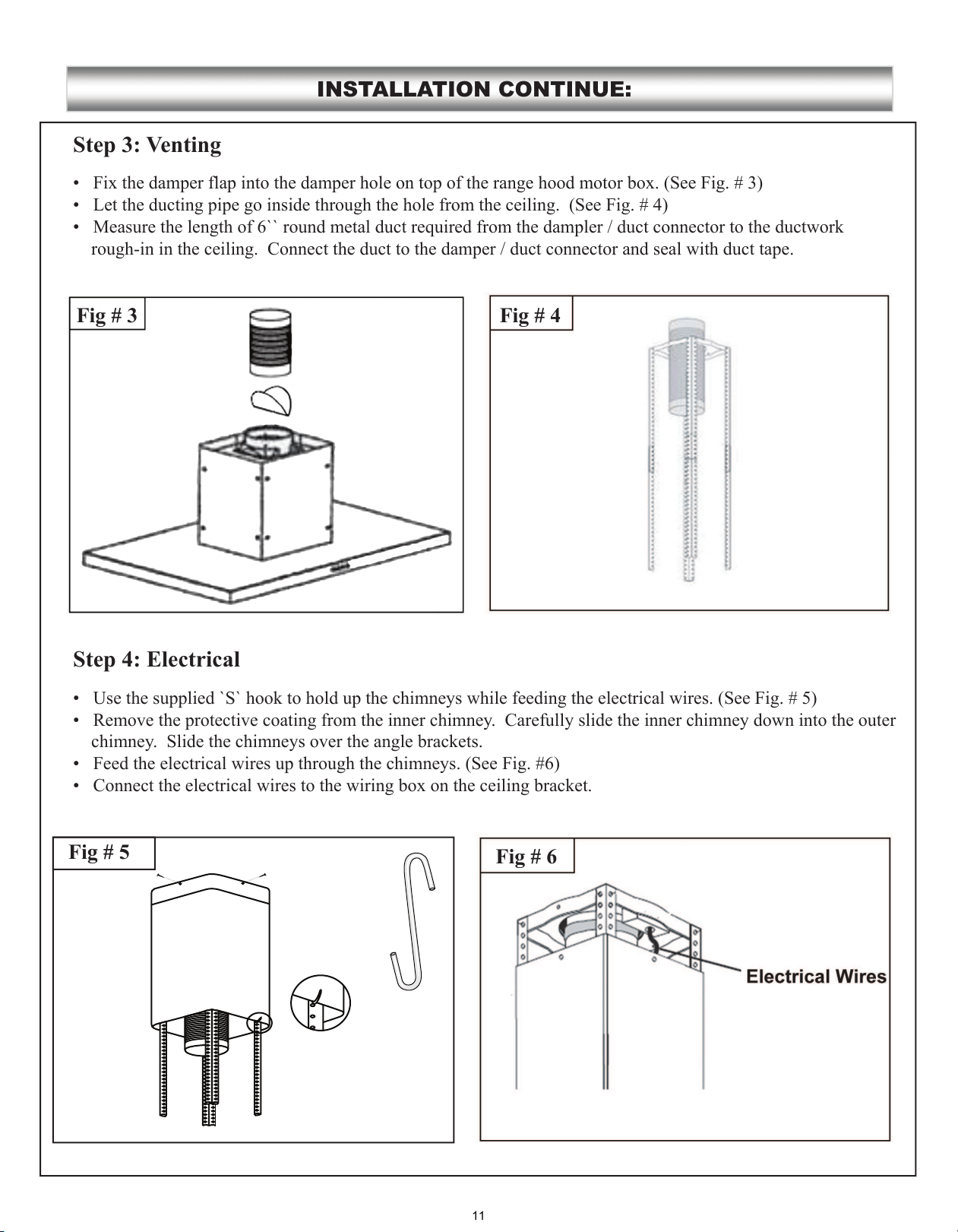
• Fix the damper flap into the damper hole on top of the range hood motor box. (
•
•
•
•
• S
•
Fig # 6
Step 3: Venting
Step 4: Electrical
Fig # 4Fig # 3
Fig # 5
.................
.................
11
INSTALLATION CONTINUE:
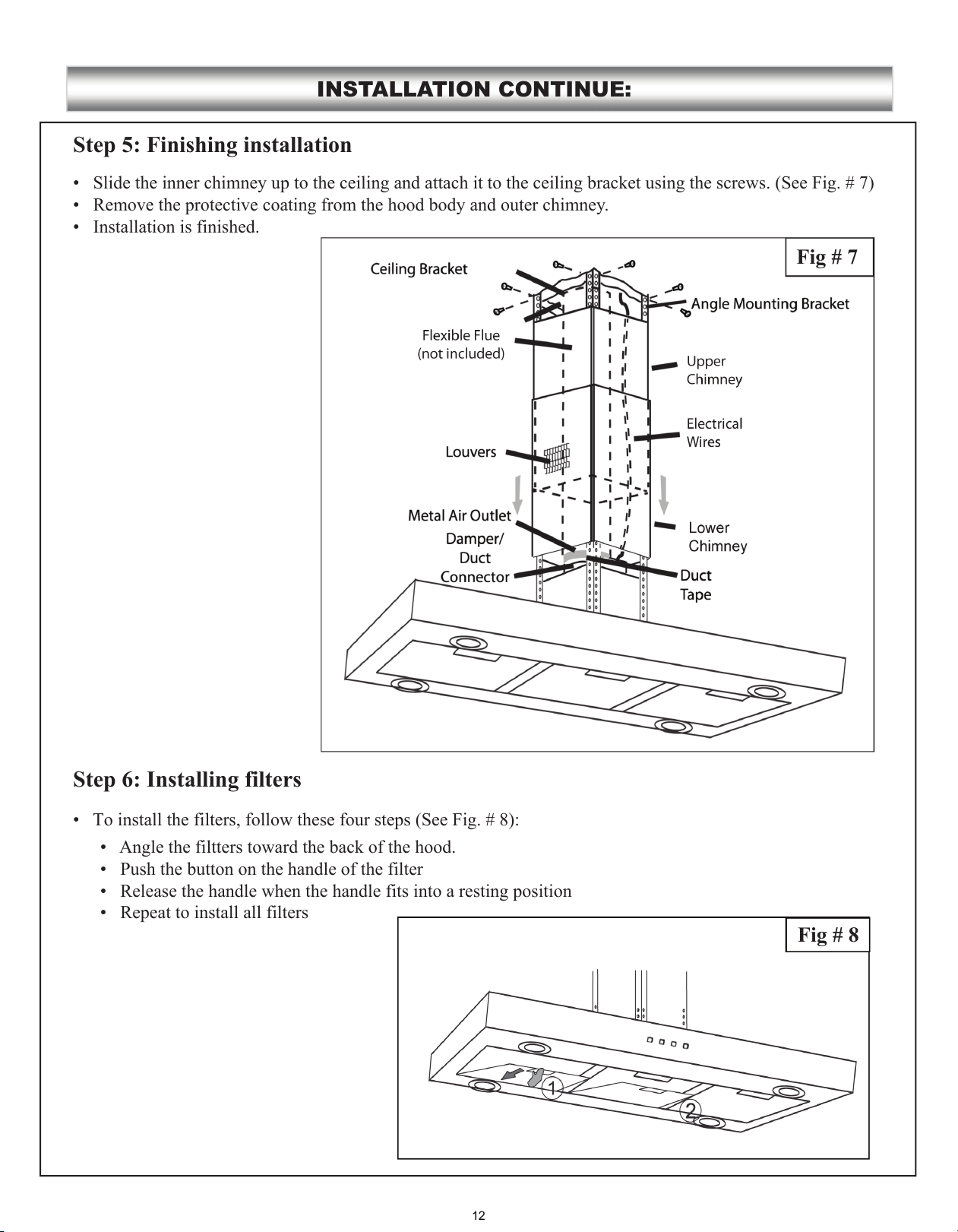
•
•
•
• T
Step 5: Finishing installation
Step 6: Installing filters
Fig # 8
Fig # 7
•
•
•
•
12
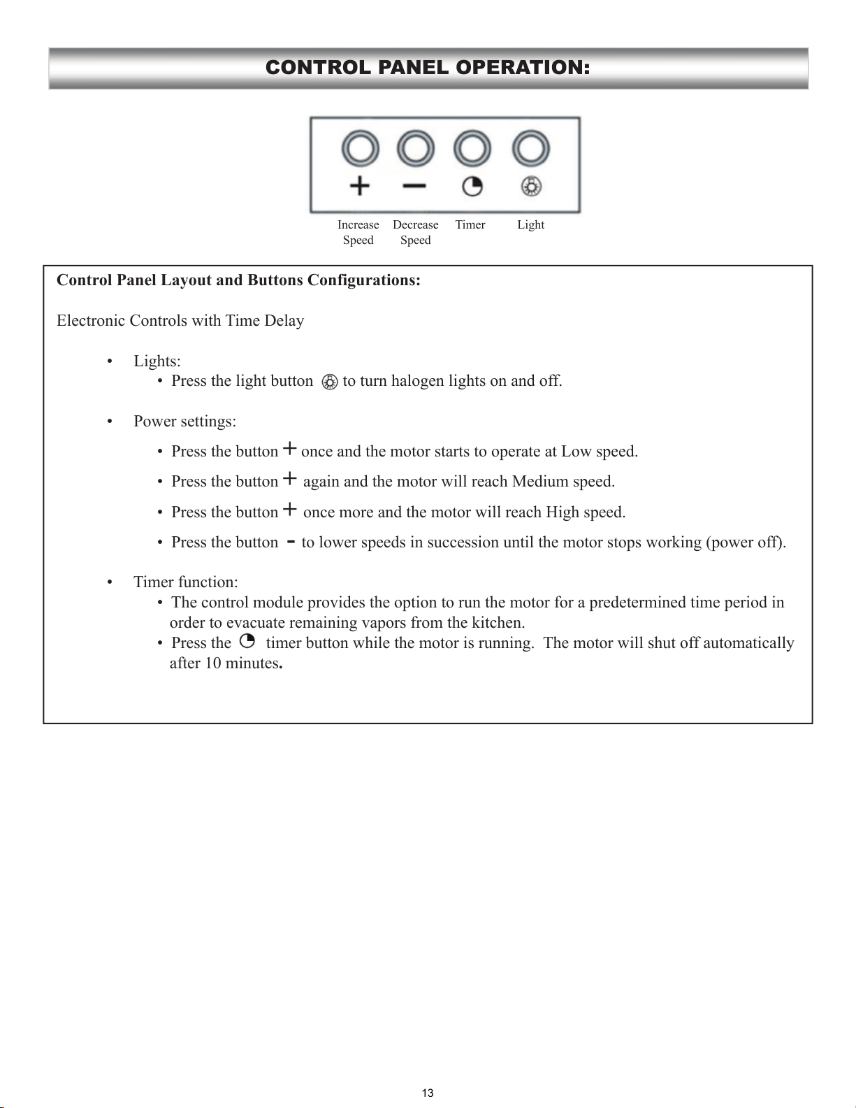
Control Panel Layout and Buttons Configurations:
Electronic Controls with Time Delay
ff.
+
+
+
- f).
T
f
.
CONTROL PANEL OPERATION:
Increase
Decrease
Timer
13
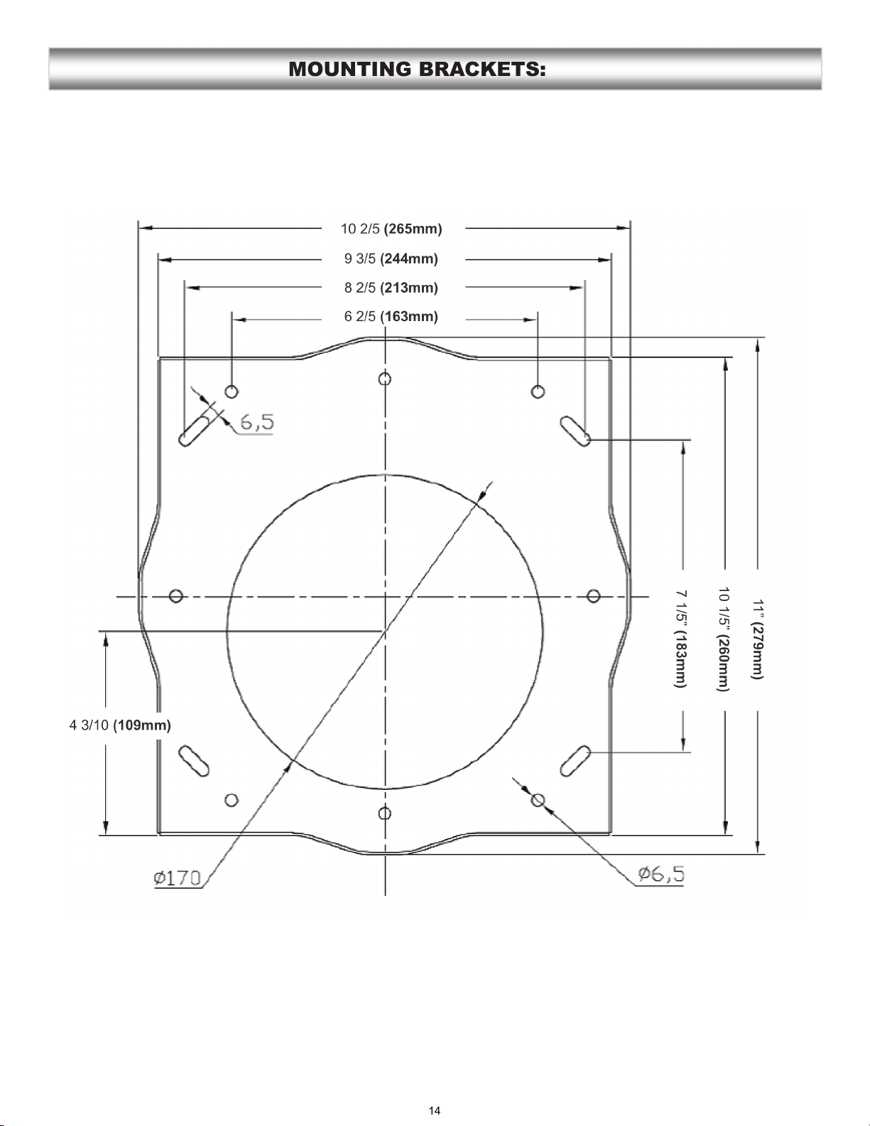
MOUNTING BRACKETS:
14
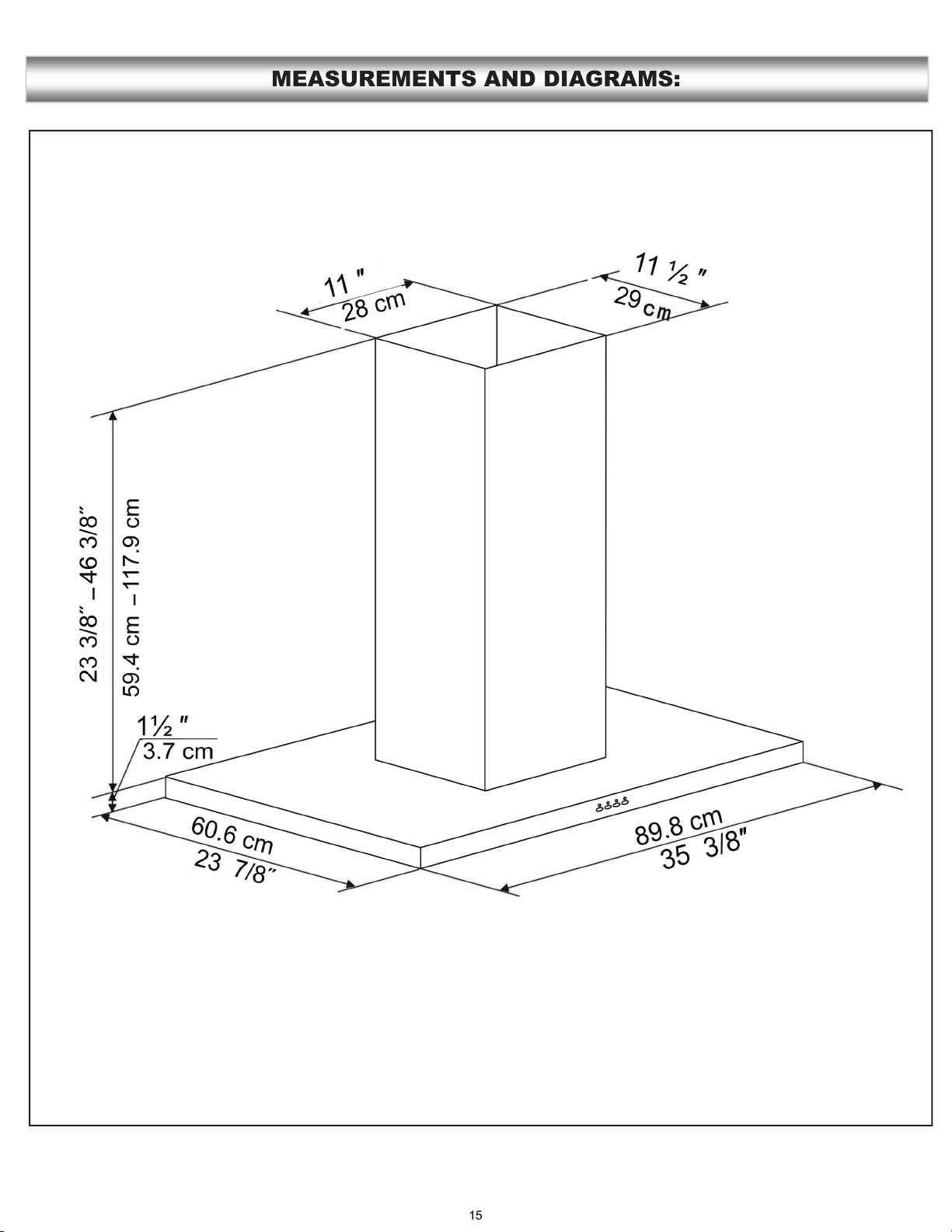
MEASUREMENTS AND DIAGRAMS:
15
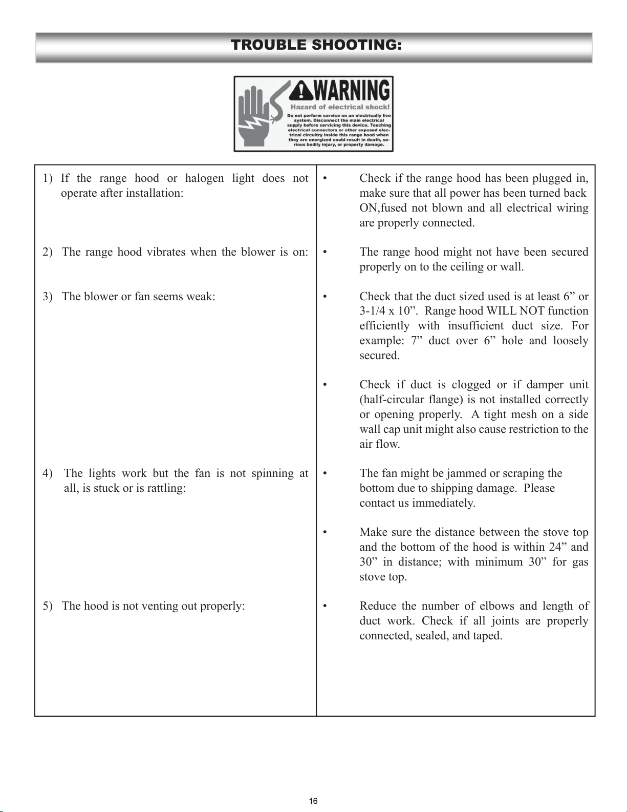
1) If the range hood or halogen light does not
operate after installation:
2) The range hood vibrates when the blower is on:
3) The blower or fan seems weak:
4) The lights work but the fan is not spinning at
all, is stuck or is rattling:
5) The hood is not venting out properly:
TROUBLE SHOOTING:
make sure that all power has been turned back
ON,fused not blown and all electrical wiring
are properly connected.
properly on to the ceiling or wall.
secured.
(half-circular flange) is not installed correctly
or opening properly. A tight mesh on a side
wall cap unit might also cause restriction to the
air flow.
bottom due to shipping damage. Please
contact us immediately.
stove top.
connected, sealed, and taped.
16
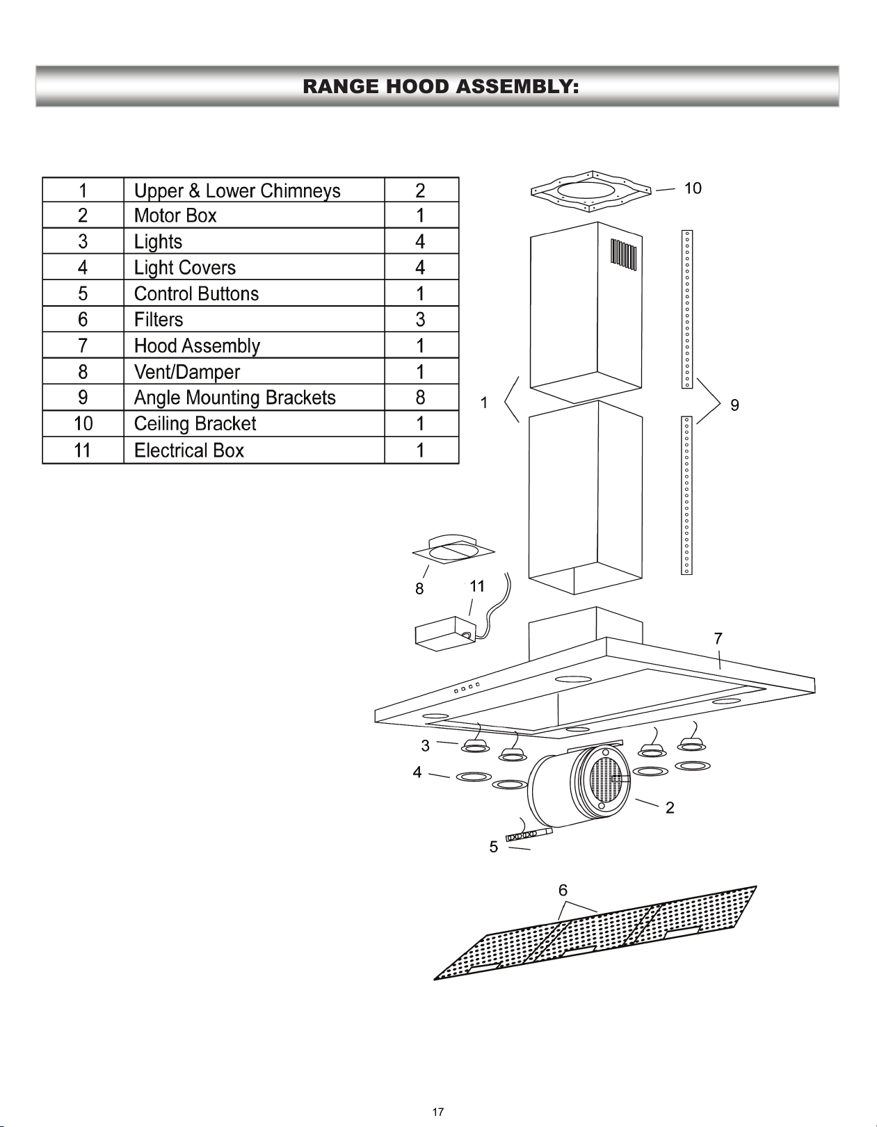
RANGE HOOD ASSEMBLY:
17
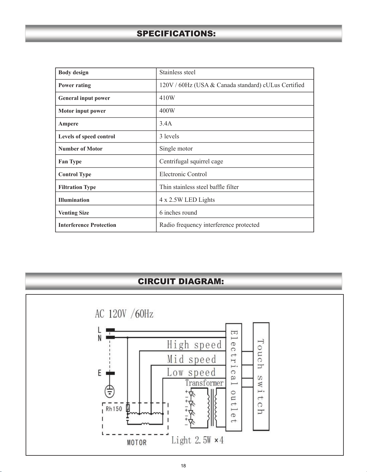
SPECIFICATIONS:
CIRCUIT DIAGRAM:
Body design
Power rating
General input power
Motor input power
Ampere
Levels of speed control
Number of Motor
Fan Type
Control Type
Filtration Type
Illumination
Venting Size
Interference Protection
Stainless steel
120V / 60Hz (USA & Canada standard)
W
W
3.A
3 levels
Single motor
Centrifugal squirrel cage
Electronic ontrol
Thin stainless steel baffle filter
4x2W
6 inches round
Radio frequency interference protected
18
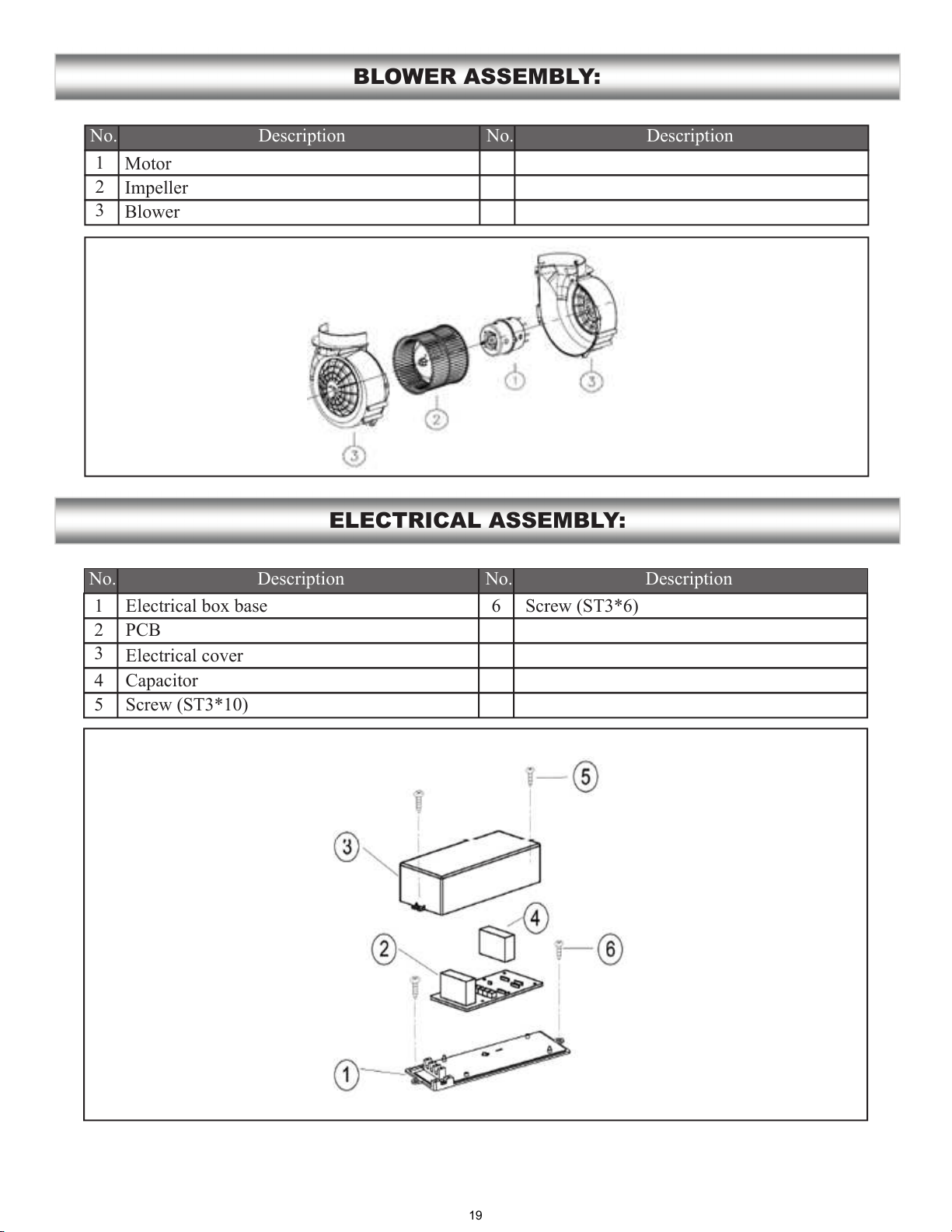
BLOWER ASSEMBLY:
ELECTRICAL ASSEMBLY:
No. No.Description Description
1
2
3
No. No.Description Description
1
2
3
4
5
6
Blower
Electrical box base
PCB
Electrical cover
Capacitor
Screw (ST3*10)
Screw (ST3*6)
19
USE AND CARE INFORMATION:
Operations:
Cleaning:
SAFETY WARNING: Never put your hand into area housing the fan while the fan is operating!
Cleaning Exterior Surfaces:
CAUTION: DO NOT leave on too long as this may cause damage to hood finish.
Cleaning Filters:
IMPORTANT:
20
LED Replacement:
•