User’s Guide
DDS-3005 USB
Operation Manual

Table of Contents
Chapter 1 Introduction…………………………………….....................................1
1.1 Introduction.....................................................................................................1
1.2 Working Principle...........................................................................................1
1.3 Hardware Specification...................................................................................1
Chapter 2 Installation.........................................................................................3
2.1 System requirements.....................................................................................3
2.2 Shape and Terminal Illustration......................................................................3
Chapter 3 Software Operations.........................................................................6
3.1 Installing the Hardware...................................................................................6
3.2 Installing the Software....................................................................................9
3.3 Run the DDS-3005 USB...............................................................................10
3.4 Choose the Wave Forms..............................................................................10
3.5 Waveform Parameter Setup.........................................................................10
3.6 Counter/ Frequency Measurement...............................................................11
3.7 Waveform Output Control.............................................................................11
3.8 Edition of Arbitrary Waveform.......................................................................12
3.9 Waveform Data Files....................................................................................12

1
Chapter 1 Introduction
1.1 Introduction
DDS-3005 USB Arbitrary Waveform Generator has one channel of arbitrary
waveform output, 8 Bits output, synchronized signal outputs, two channels of
Counter/Frequency Measurement inputs, 8 Bits input and external trigger input.
User can edit the waveform arbitrarily by the mouse or choose the regular
waveforms such as Sine, Square, Tri-angle, Saw-tooth, TTL, White Noise,
Gauss Noise, Trapezia, Exponent, AM and FM. The parameters, such as
amplitude, frequency and offset, are also settable. The data format of
DDS-3005 USB is completely compatible with that of Tektronix; it can directly
read the waveform data files produced by the Tektronix oscilloscope or
Tektronix waveform editor software and redisplay the waveform. DDS-3005
USB adopts the DDS technology so that it has the advantages of high
frequency accuracy, high waveform resolution, high reliability, and wide
software support. It can be widely used in the various kinds of electronics labs
and it offers complete interface for second time development to be jointlessly
inserted into other auto-measuring systems.
1.2 Working Principle
The PC transfer the waveform data to the memorizer of the signal generator
via the USB bus, the ID counter cycles and send the period waveform data to
the DAC circuits, the DDS (Direct Digital Synthesized) circuit produces the
corresponding DAC refreshing clock. The waveform of DAC is outputted
through the Cache magnifier, Low Pass Filter, and the Magnifier. The
frequency counter can test the external frequency.
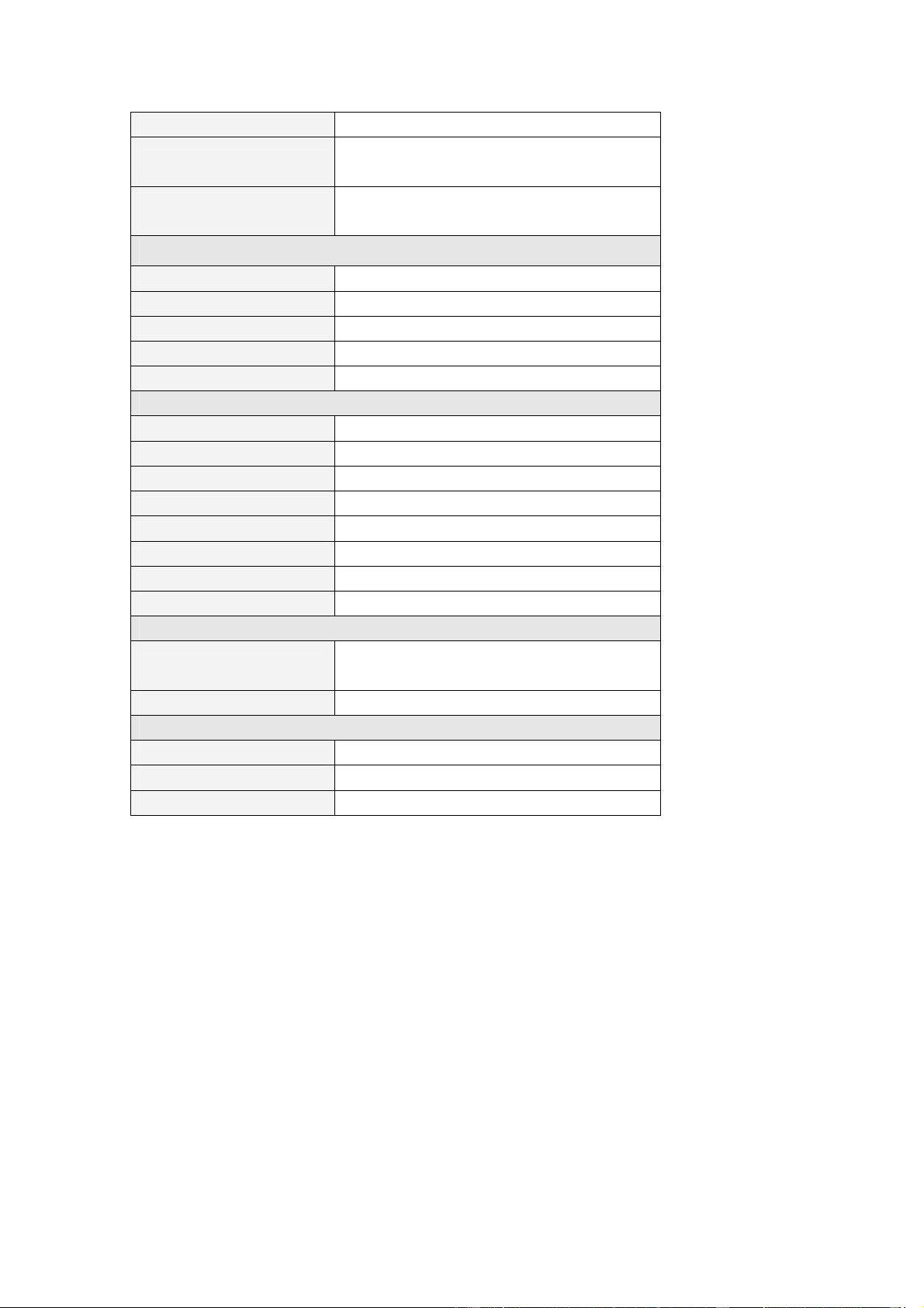
1.3 Hardware Specification
Waveform Output Channel
Frequency Range 0.1Hz(DC)~5MHz
Resolution 0.01Hz
DAC Clock
0~50MHz Continuously adjustable, in
step of 0.2Hz
Channels 1CH waveform output
Memory Depth 256KSa
Vertical Resolution 14 Bits
Stability <30ppm
Amplitude ±10V Max.
Output Impedance 50 Ω
2
Output Current 50mA Vpeak=100mA
Low Pass Filter
5MHz, 1MHz, 100KHz, 10KHz, 1KHz
Programmable Control
Harmonic Wave
distortion
-65dBc(1KHz), -53dBc(10KHz)
Frequency Counter Channel 1
Range DC~25MHz
Input Amplitude 400mVpp~25Vpp
Coupling Mode AC, DC Programmable
Accuracy ±Time Base Error ±1 Count
Input Impedance > 50KΩ
Frequency Counter Channel 2
Range 25MHz~2.7GHz
Input Power ±20dbm
Coupling Mode AC
Accuracy ±Time Base Error ±1 Count
Input Impedance 50 Ω
Standard Frequency 25MHz
Frequency Stability 20 ppm max.
Aging Rate ±1 ppm/year
Digital Input and Output
Bits
8 Bits+ Synchronized Signal 1 Bit +
External Signal 1 Bit
Level 3/5V TTL/CMOS
Working Environment
Working Temperature 0~70 Centigrade
Working Humidity 0~65%
Weight 0.7Kg

3
Chapter 2 Installation
2.1 System requirements
l Minimum System Requirements
Operating System
Windows 98/2000/XP
Memory
128Mbyte
Graphic Card
Microsoft DirectX supported
Screen resolution: 1024x768
Color depth: 16bit
l Recommended System Requirements
Operating System
Windows 98/2000/XP
Memory
256Mbyte
Graphic Card
Microsoft DirectX supported
Screen resolution: 1024x768
Color depth: 16bit
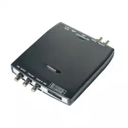
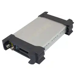
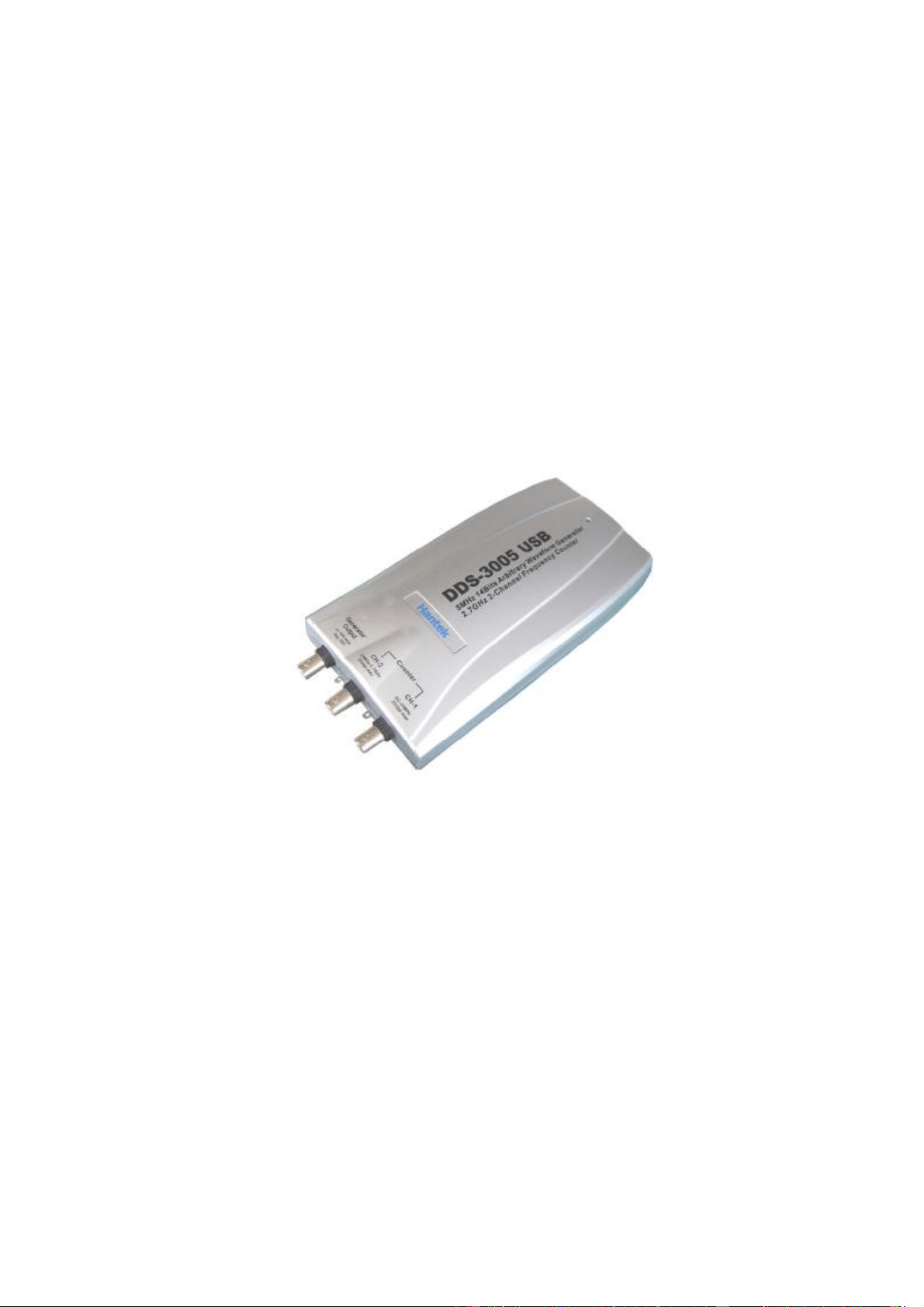
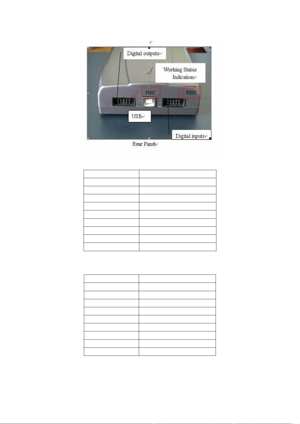
2.2 Shape and Terminal Illustration
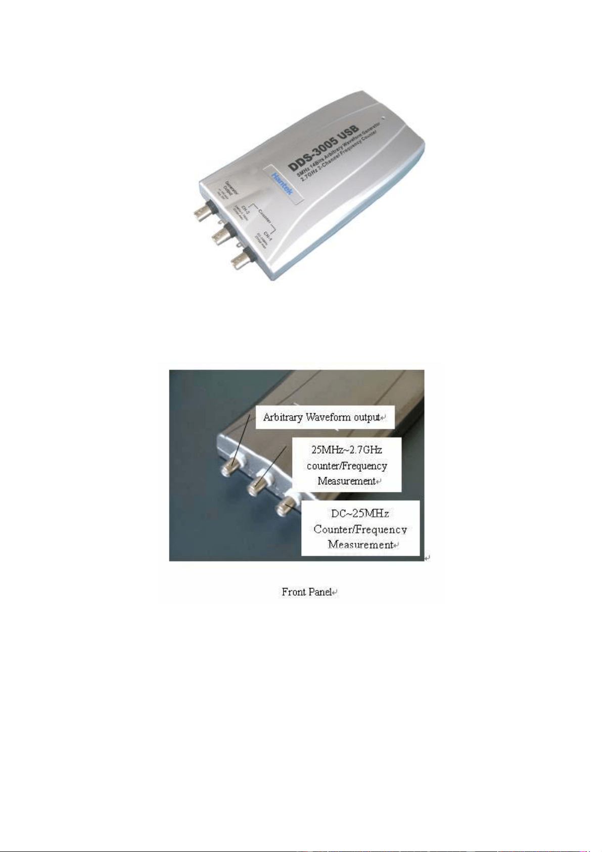
4
DDS-3005 USB Shape
5
PIN1 Bit7
PIN2 Bit6
PIN3 Bit5
PIN4 Bit4
PIN5 Bit3
PIN6 Bit2
PIN7 Bit1
PIN8 Bit0
PIN9 Synchronized Signal Output
PIN10 Digital Ground
Digital Output Port Definition
PIN1 Bit7
PIN2 Bit6
PIN3 Bit5
PIN4 Bit4
PIN5 Bit3
PIN6 Bit2
PIN7 Bit1
PIN8 Bit0
PIN9 External Trigger Input
PIN10 Digital Ground
Digital Input Port Definition
6
Chapter 3 Software Operations
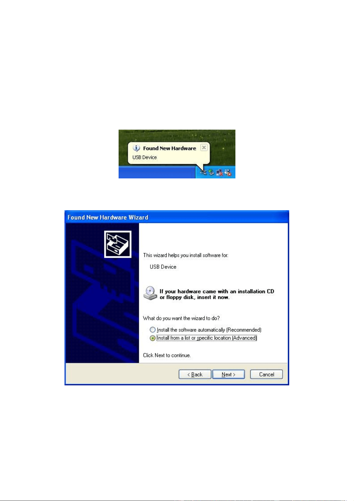
3.1 Installing the Hardware
Connect the USB instrument to the USB port through the USB cable, the PC
prompts that new USB device is found.
The PC will automatically find the new USB device and choose the nominated
directory to install the driver.
Choose the correct directory of the driver through the browser or search in the
CD driver.
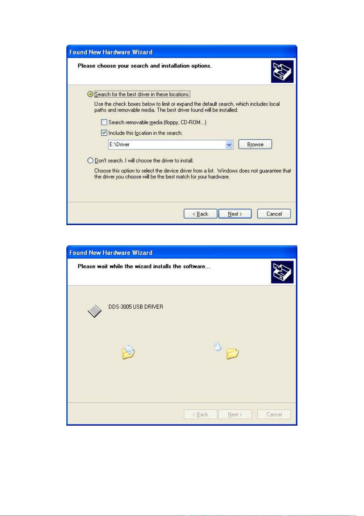
7
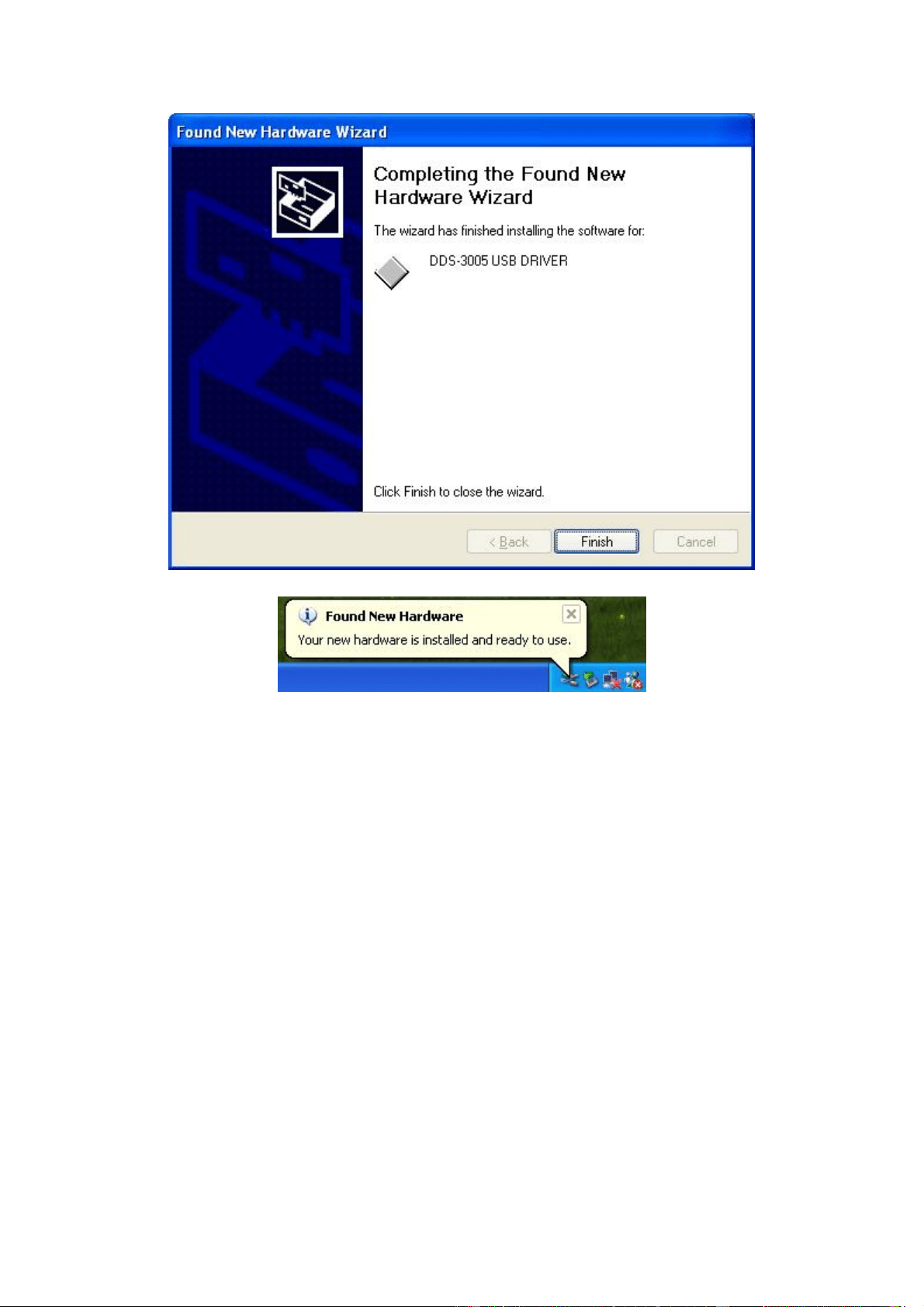
Click "Continue" to finish the installation.
8
The system will notify that the new USB device can work normally now.
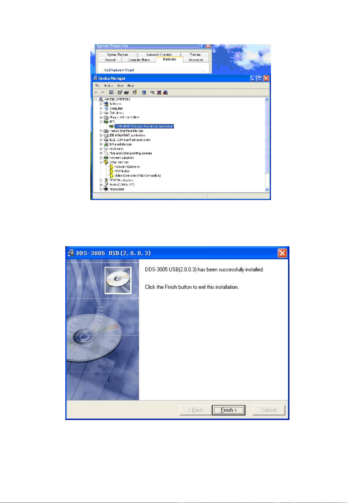
After the successfully installation, in the Device Manager, you can see the
DDS-3005 USB device.
9
3.2 Installing the Software
The setup software of DDS-3005 USB is in the CD, run the Setup.exe to install
the software.
10
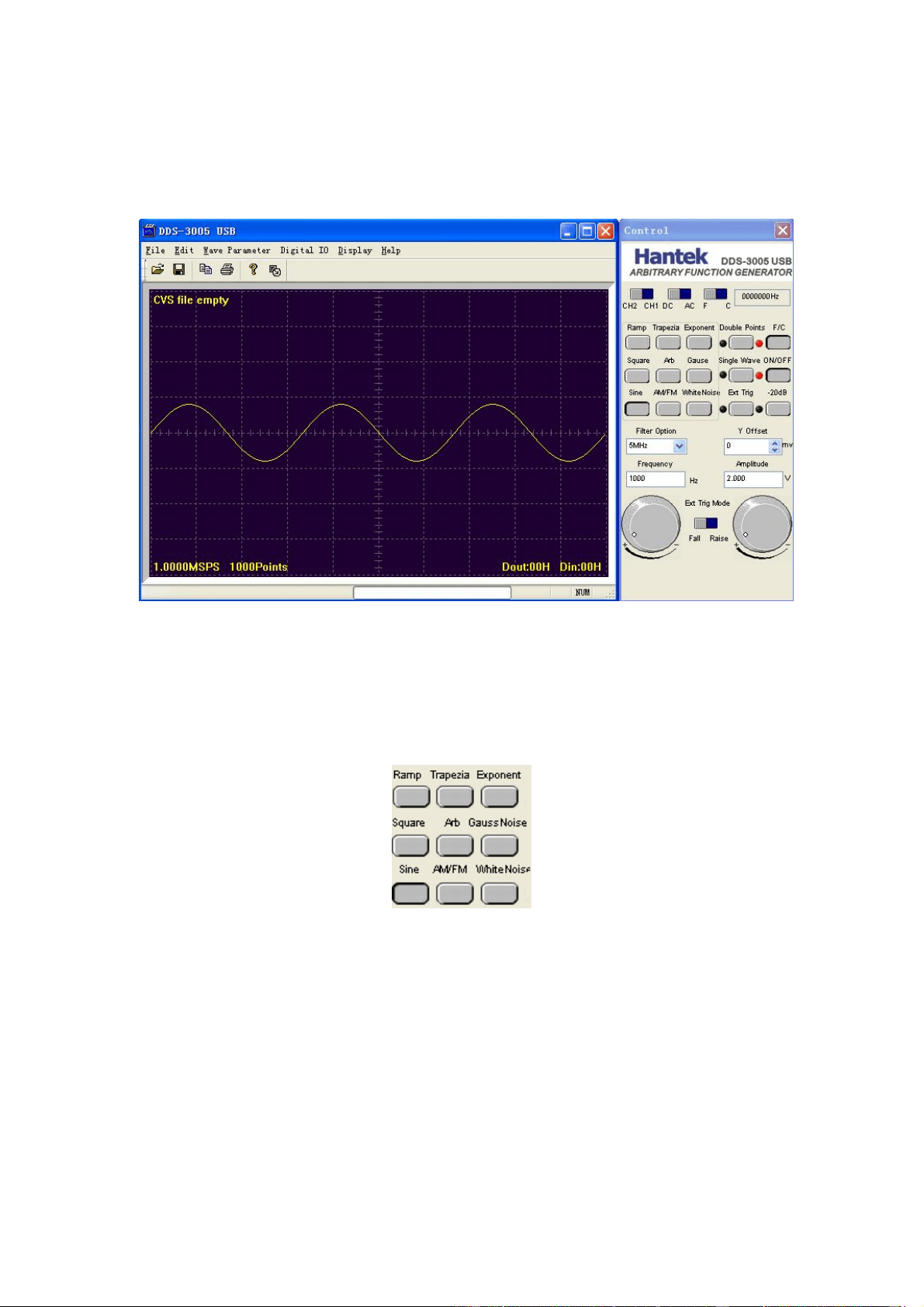
3.3 Run the DDS-3005 USB
Click "Start"- "Program"-"DDS-3005 USB"-"DDS-3005 USB" to go into the main
window, shown as below:
3.4 Choose the Wave Forms
Press down any button of certain waveform to switch to the output of such kind
of waveform. When switch to arbitrary waveform from other kind of waveform,
the edition work can be done on the original wave form.
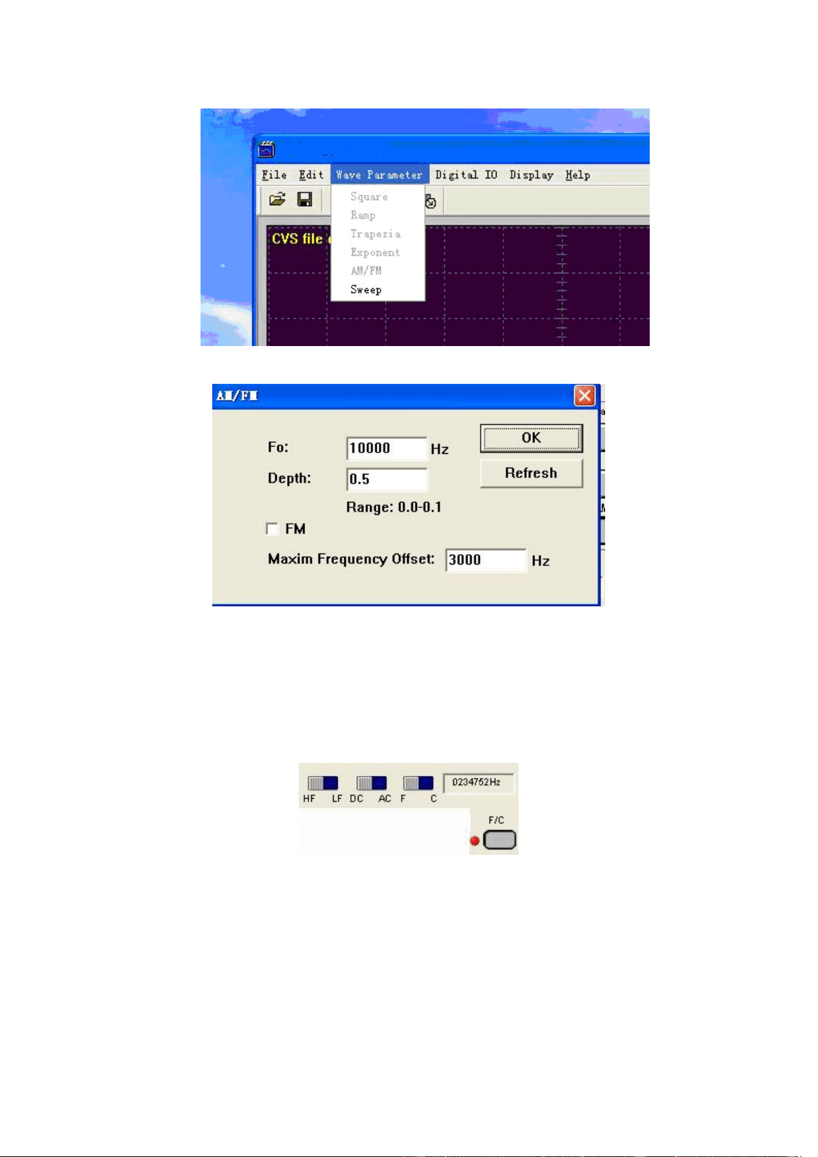
3.5 Waveform Parameter Setup
Select the "Parameters" in the Menu, there are the choices for setting of
various waveform parameters.
11
Example "modulation Signal":
Set the parameters in the dialog box.
3.6 Counter/ Frequency Measurement
To measure by the buttons shown as below:
Including "High Frequency/ Low Frequency”, "Coupling Mode" "Frequency
Measure/ Counter" and the function’s "On/Off".
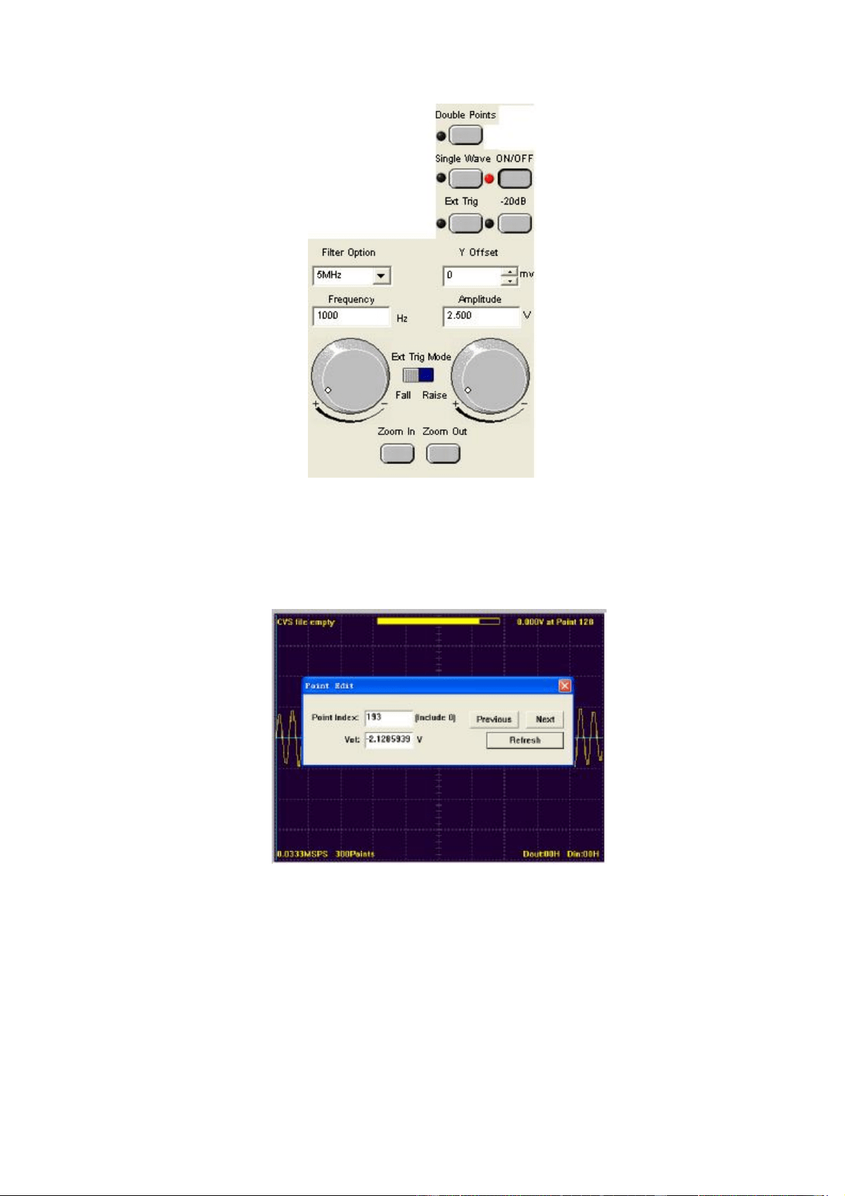
3.7 Waveform Output Control
By the following buttons to control the output dot numbers, trigger mode,
output amplitude, and limit frequency of the wave filter.
12
3.8 Edition of Arbitrary Waveform
Choose the "Arbitrary Dot Edit" in the "Edit" Menu, or double-click the display
window to edit each dot, or use the mouse the draw the waveform.
3.9 Waveform Data Files
The data format of DDS-3005 USB is ".CSV". Its format is compatible with the
CSV file produced by the Tektronix ARBExpress software. User can edit or set
up the required CSV waveform and also use Excel to open and edit the CSV
wave files.
Warn: Any usage beyond the limit of the input & output signal ports as well as

13
strong electrical field and static may cause the abnormal working or even
damage to the instrument.