
Operator's manual
Z4822/968999301
Z4824/968999303
Please read the operator's manualcarefully and make
sure you understand the instructions before using the machine.
English
Husqvama'- Z4822 Page 1 of 2
Great experience
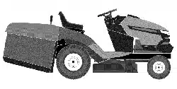
Z4822 New!
For maneuverability, efficiency and convenience in a
homeowner zero-turu package, the Residential series really
delivers. True zero-turn performance with twin,
maintenance free integrated zero-turn transmissions, heavy-
duty front casters and a rugged stamped and embossed
frame. High perfomaance air induction cutting decks allow
side discharge or optional mulch and collection capability.
Convenient control placement, foam padded steering levers
and adjustable seat travel make these units fun to operate.
Maintenance-Free
Transmission
Wom-y free performance
with maintenance free,
integrated zero-turn
transmissions.
Heavy-Duty Frame
Doxable, one piece
stamped and embossed
frame for structural
strength.
Height Control
Foot activated deck lift and
cutting height control
allows for easy, quick
adjustments.
.....7%
,'7<?
High Performance Deck
High performance air
induction cutting decks are
mulch, side discharge and
collection capable.
Convenience
Convenient control panel
placement makes it a
breeze to operate.
Optional Accessories
Optional utility bed,
headlights and arm rests
add versatility.
Specifications
Engine:
Manu_cturer
Power
Starer
Transmission:
YvDe
Speed forward, rain-
max
Speed reverse, rain-
max
Tvres. front/rear
Bri_s & Stratton
22 hD
decttic
Twin IZT
0-6 miles/h
0-3.5 miles/h
18 9.5 x 8 / 4.10x3.50-5"
Equipment
Cuttin_ width 48"
http ://www.usa.husqvarna.com/node2183 .asp?print=-On&cid = 151 &pid = 102 7/19/06

Husqvmma"-Z4822 Page2of 2
Cuttin_ height 1.5-4.5 in 1/2" increments"
Number of blades 3
Blade length 19"
Anti-scalD rollers 4
Sprung standard Standard w/o armrest
seat
Dual levers with foam padded
hand _iDs
12 g'4.uge, stamped steel,
powder coated
Blade engagement
Deck construction
Productivity
Overall dimensions
Base machine
(LxWxI-B
72x59x42"
http://www.usa.husqvarna.conffnode2183.asp?print=On&cid = 151 &pid = 102 7/19/06
OPERATOR'S MANUAL
RIDER
Z SERIES
Contents
Contents ................................................................... 1
Introduction ............................................................. 3
Congratulations.................................................... 3
General ................................................................ 3
Drivingand Transport on PublicRoads ............... 3
Towing ................................................................. 3
Operating............................................................. 3
Good Service ....................................................... 4
ManufacturingNumber ........................................ 4
Symbols and Decals ............................................... 5
Safety Instructions .................................................. 7
General Use......................................................... 7
Personal Safety Equipment................................. 9
Drivingon Slopes................................................. 9
Children.............................................................. 10
UtilityBox........................................................... 10
Maintenance ...................................................... 11
Transport............................................................ 13
Customer responsibilities................................... 14
Controls ................................................................. 16
Control Locations............................................... 16
1. MotionControl Levers.................................... 17
2. Seat adjustment knobs.................................. 18
3. Fuses ............................................................. 18
4. By passlinkages ............................................ 19
5. Refueling........................................................ 20
6. Blade switch................................................... 20
7. IgnitionSwitch................................................ 21
8. Choke Control................................................ 21
9. ThrottleControl.............................................. 21
10. Hour Meter................................................... 22
11. ParkingBrake .............................................. 22
12. Cuttingheight pedal..................................... 23
Accessories........................................................ 23
Operation ............................................................... 24
Training.............................................................. 24
BeforeStarting................................................... 25
Starting the Engine ............................................ 25
To start an engine with a weak battery.............. 28
Running.............................................................. 29
Operating on hills............................................... 30
MowingTips....................................................... 31
Stopping the Engine........................................... 32
Movingby Hand ..................................................... 33
Maintenance ......................................................... 34
Maintenance Schedule ...................................... 34
Battery ............................................................... 36
Ignition System .................................................. 37
Checking the Safety System ............................. 38
Checking the Engine's Cooling Air Intake ......... 39
Checking and Adjusting the Throttle Cable ....... 39
Replacing the Air Filter ...................................... 40
Replacing the Fuel Filter ................................... 41
Checking Tire Pressures ................................... 41
Checking the Parking Brake .............................. 41
Checking the V-belts ......................................... 42
Deck belt ........................................................... 42
EZT belt............................................................. 44
Checking the Blades ......................................... 45
Adjusting the Mower Deck ................................ 46
Cleaning and Washing ...................................... 50
Caster Wheels ................................................... 50
Hardware ........................................................... 50
Lubrication ............................................................ 51
Lubrication Schedule ......................................... 51
General ............................................................. 51
Lubricating the Cables ...................................... 52
Lubricating in Accordance with the Lubrication
Schedule ........................................................... 52
Trouble Shooting Guide ...................................... 56
Storage .................................................................. 59
Winter Storage .................................................. 59
Service .............................................................. 59
Wiring diagram ..................................................... 60
Technical Data...................................................... 61
Accessories....................................................... 63
Torque Specifications ........................................ 63
Conformity Certificates ........................................ 64
USA requirements ............................................. 64
Service Journal .................................................... 65
Delivery Service ................................................ 65
After the First 5-8 Hours .................................... 66
25-Hour Service ................................................ 67
50-Hour Service ................................................ 68
I g0-Hour Service .............................................. 69
300-Hour Service .............................................. 70
At Least Once Each Year .................................. 71
English-1
WARNING!
Failure to follow cautious operating practices can result in serious injury to the
operator or other persons. The owner must understand these instructions, and must
allow only trained persons who understand these instructions to operate the mower.
Each person operating the mower must be of sound mind and body and must not be
under the influence of any mind altering substance.
WARNING!
Engine exhaust, some of its constituents, and certain vehicle components contain or
emit chemicals known to the State of California to cause cancer and birth defects or
other reproductive harm.
WARNING!
Battery posts, terminals and related accessories contain lead and lead compounds,
chemicals known to the State of California to cause cancer and birth defects or other
reproductive harm. Wash hands after handling.
English-2
INTRODUCTION
Introduction
Congratulations
Thank you for purchasing a Husqvama ride-on mower. This machineis built for the greatest efficiencyand
rapid mowing pdmarily of large areas. Controls in one place and a hydrostatic transmission regulated by
steering controls also contribute to the machine's performance.
This manual is a valuable document. Following the instructions (use, service, maintenance, etc.) by all who
operate this machine can considerably increase the lifespan of your machine and even increase its resale
value. It is also very important to follow the instructions for the safety of you and others.
If you sell your machine, be sure to give the operator's manual to the new owner.
The final chapter of this operator's manual comprises a Service Journal. Ensure that service and repair
work is documented. A well kept service joumal reduces service costs for the saason-basad maintenance
and affects the machine's resale value. Take the operator's manual along when the machine is left to the
workshop for service.
General
In this operator's manual, left and right, backward and forward are used in relation to the machine's normal
ddving direction.
Continuous dedication to improve our products require that specifications and design are subject to change
without notice.
Driving and Transport on Public Roads
Check applicable roadtrafficregulations beforetransportingon publicroads. Ifthe machine istransported,
you must always useapproved fasteningequipmentand ensurethat the machine iswell anchored. DO
NOT operate this machineon publicroadways.
Towing
Do not towthis machine, itmay cause damage to the drive system.
Do not tow anytrailers,etc withthis mower.They may jackknifeor overturncausingdamage tothe mower
and possiblysedous injuryto the operator.
Operating
This machine is constructedonlyfor mowinggrass on lawns and otherfree and even ground without
obstacles such as stones, tree stubs, etc. The machine can also be used for other tasks when equipped
with special accessories provided by the manufacturer, for which the operating instructions are provided in
conjunction with delivery. All other types of useere incorrect. The manufacturer's directions concerning
operation, maintenance, and repairs must be carefully followed.
Lawnmowers and all power equipment, can be potentiallydangerous if used improperly.Safety requires
good judgement, careful use in accordance with these instructions and common sense.
The machine must onlybe operated, maintained, and repaired by persons that are familiar withthe
machine's specialcharacteristics and who are well versed in the safety instructions. Use only approved
repair parts to maintain this machine.
Accident prevention regulations, other general safety regulations, occupationalsafety rules, and traffic
regulations must be followed without fail.
Unauthorized modifications to the design ofthe machine may absolve the manufacturerfrom liability for
any resulting personal injury or property damage.
English-3
INTRODUCTION
Good Service
Husqvama's productsare soldallover the worldand onlyinspecialized retailstoreswithcompleteservice.
This ensuresthat you as a customerreceive onlythe best supportand service.Beforethe productis
delivered, the machinehas, for example, been inspectedand adjustedby yourretailer,see the certificate
inthe Service Journal in thisoperator's manual.
When you need spare parts or supportin servicequestions,warranty issues,etc., please consult
the following professional:
This Operator's Manual belongs to the Engine Transmission
machinewith manufacturingnumber:
Manufacturing Number
The machine's manufacturing number can be found on the printedplate affixedto the leftin the engine
compartment.Stated on the plate, from thetop are:
The machine's typedesignation(I.D.).
The manufacturer'stype number (Model).
The machine's serialnumber (Serial no.)
Please state the type designationand serial numberwhen orderingspare parts.
The engine's manufacturingnumber isstamped on one ofthe valve covers.
The plate states:
The engine's model.
The engine's type.
Code
Please state these when orderingspare parts.
The Hydro Drive IZ gears have a barcede decal affixed tothe rear ofthe gears.
English_l
SYMBOLS AND DECALS
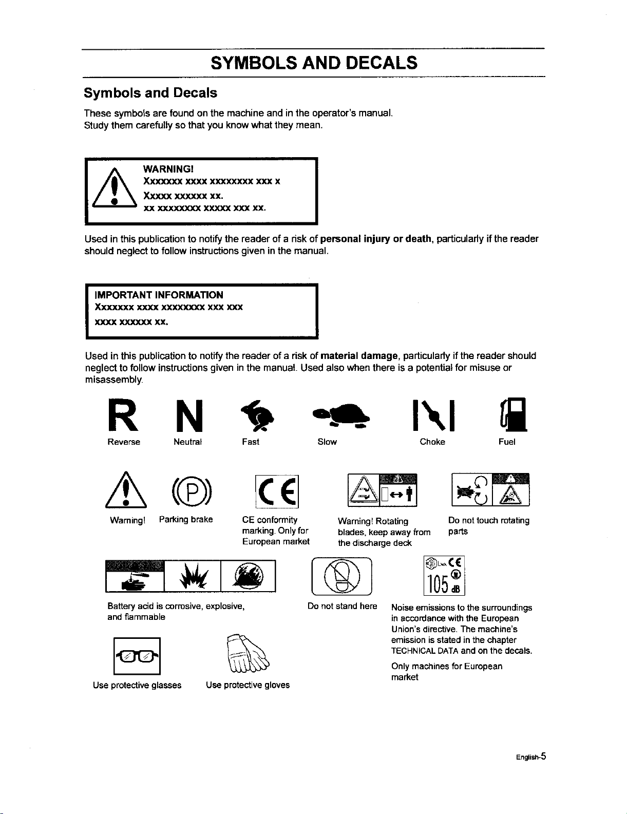
Symbols and Decals
These symbolsare found on the machineand in the operator'smanual.
Studythem carefullyso thatyou knowwhat they mean.
WARNING!
Xxxxxxx xxxx xxx_xxx xxx x
Xxxxx xxxxxx xx.
XX X](XXXXXX XXXXX XXX XX.
Used in this publication to notify the reader of a riskof personal injury or death, particularlyifthe reader
shouldneglectto followinstructionsgiven inthe manual.
I
IMPORTANT INFORMATION
Xxxxxxx xxxx xxxxxxxx xxx xxx
XXXX XXXXXX XX.
I
Used inthis publication to notify the reader ofa risk of material damage, particularlyif the reader should
neglecttofollow instructionsgiven inthe manual. Used also when there is a potentialfor misuseor
misassembly.
R N I',,I
Reverse Neutral Fast Slow Choke Fuel
Warning! Parkingbrake CEconformity WamingtRotating
marking.Onlyfor blades,keepawayfrom
Europeanmarket thedischargedeck
Batteryacid iscorrosive, explosive,
and flammable
Useprotectiveglasses
%
Useprotectivegloves
Donotstandhere
Do not touchrotating
parts
Noiseemissionstothesurroundings
inaccordansewiththeEuropean
Union'sdirective.Themachine's
emissionisstatedinthechapter
TECHNICALDATAandonthedecals.
Only machines for European
market
English-5
SYMBOLS AND DECALS
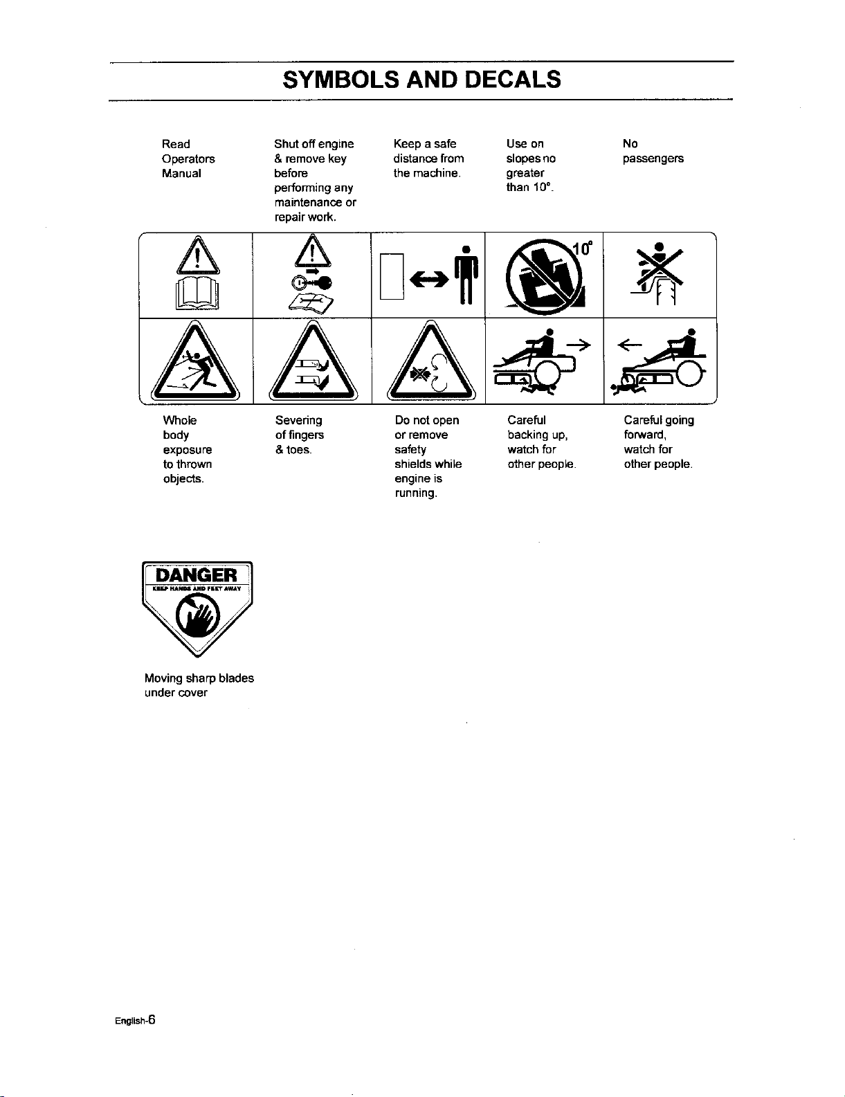
Read
Operators
Manual
A
VVhole
body
exposure
tothmwn
o_e_s.
Shut off engine
& remove key
before
performingany
maintenance or
repair work.
&
A
Keep a safe Use on
distancefrom slopesno
the machine, greater
than f0 °.
Sevedng
offingers
& toes.
Do not open
or remove
safety
shieldswhile
engine is
running.
Careful
backing up,
watch for
other people.
No
passengers
<__
Careful going
forward,
watch for
other people.
DANGER
Moving sharp blades
undercover
English-6
SAFETY INSTRUCTIONS
Safety Instructions
These instructionsare for your safety,Read them carefully.
WARNINGI
This symbol means that important safety instructions need to be emphasized. It
concerns your safety.
IMPORTANT: THIS CUFFING MACHINE iS CAPABLE OF AMPUTATING HANDS AND FEET AND
THROWING OBJECTS. FAILURE TO OBSERVE THE FOLLOWING SAFETY INSTRUCTIONS COULD
RESULT IN SERIOUS INJURY OR DEATH.
I
General Operation
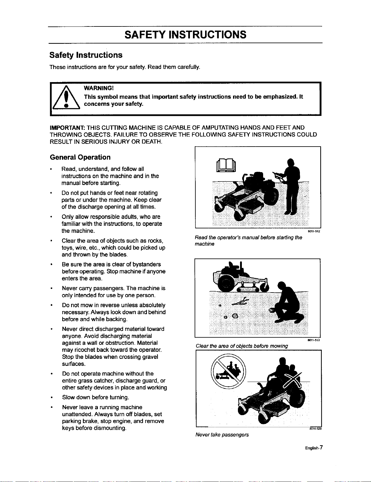
Read, understand,and follow all
instructions on the machine and in the
manual before starting.
Do not put hands or feet near rotating
parts or under the machine. Keep clear
of the discharge opening at aUtimes.
Only allow responsible adults, who are
familiar with the instructions, to operate
the machine.
Clear the area of objects such as rocks,
toys, wire, etc., which could be picked up
and thrown by the blades.
Be sure the area is clear of bystanders
before operating. Stop machine if anyone
enters the area.
Never carry passengers. The machine is
only intendedfor use by one person.
Do not mow in reverse unless absolutely
necessary. Always look down and behind
before and while backing.
Never direct discharged material toward
anyone. Avoid discharging material
against a wall or obstruction. Materiel
may ricochet back toward the operator.
Stop the blades when crossing gravel
surfaces.
Do not operate machine without the
entire grass catcher, discharge guard, or
other safety devices in place and working
Slow down before turning.
Never leave a running machine
unattended. Always turn off blades, set
parking brake, stop engine, and remove
keys before dismounting.
8011 512
Readtheoperator'smanualbeforestartingthe
machine
80H-513
Clear the area of objects before mowing
Never take passengers
8011_520
English-7
SAFETY INSTRUCTIONS
Disengage blades when not mowing.
Shut offengine and wait for all parts to
come toa completestop beforecleaning
the machine, removingthe grass
catcher,or uncloggingthe discharge
guard.
Operate machineonlyindaylightor good
artificiallight.
Do notoperate the machinewhile under
the influenceof alcoholor drugs.
Watch for trafficwhen operating near or
crossingroadways.
Use extra care when loadingor
unloadingthe machineintoa trailer or
truck.
Always wear eye protection when
operating machine.
Data indicates that operators,age 60
years and above, are involvedin a large
percentage ofridingmower-related
injudes.These operatorsshould
evaluate their abilityto operate the riding
mower safelyenoughto protect
themselves and othersfrom serious
injury.
Followthe manufacturer's
recommendationfor wheel weightsor
counterweights.
Never allowchildrenorotherpersonsnot
trained in the useof the machineto use
or serviceit. Locallaws may regulate the
age ofthe user.Anyone who operates
this machineshouldfirstread and
understand this Operator's Manual.
Keep machinefree ofgrass, leaves or
otherdebrisbuild-upwhichcan touchhot
exhaust / engine partsand burn. Do not
allowthe mower deckto plowleaves or
otherdebris whichcan cause build-upto
occur.Clean any oilor fuel spillage
before operatingor storingthe machine.
Allow machineto cool before storage.
WARNING!
Engine exhaust and certain
vehicle components contain
or emit chemicals considered
to cause cancer, birth defects,
or other reproductive system
damage, The engine exhaust
contains carbon monoxide,
which is a odorless, colorless,
poisonous gas, Do not use the
machine in enclosed spaces,
English-8
SAFETY INSTRUCTIONS
Personal Safety Equipment
WARNING!
When using the machine, approved personal protective equipment (shown in
illustrations) shall be used. Personal protective equipment cannot eliminate
the risk of injury but itwill reduce the degree of injury if an accident does
happen. Ask your retailer for help in choosing the right equipment.
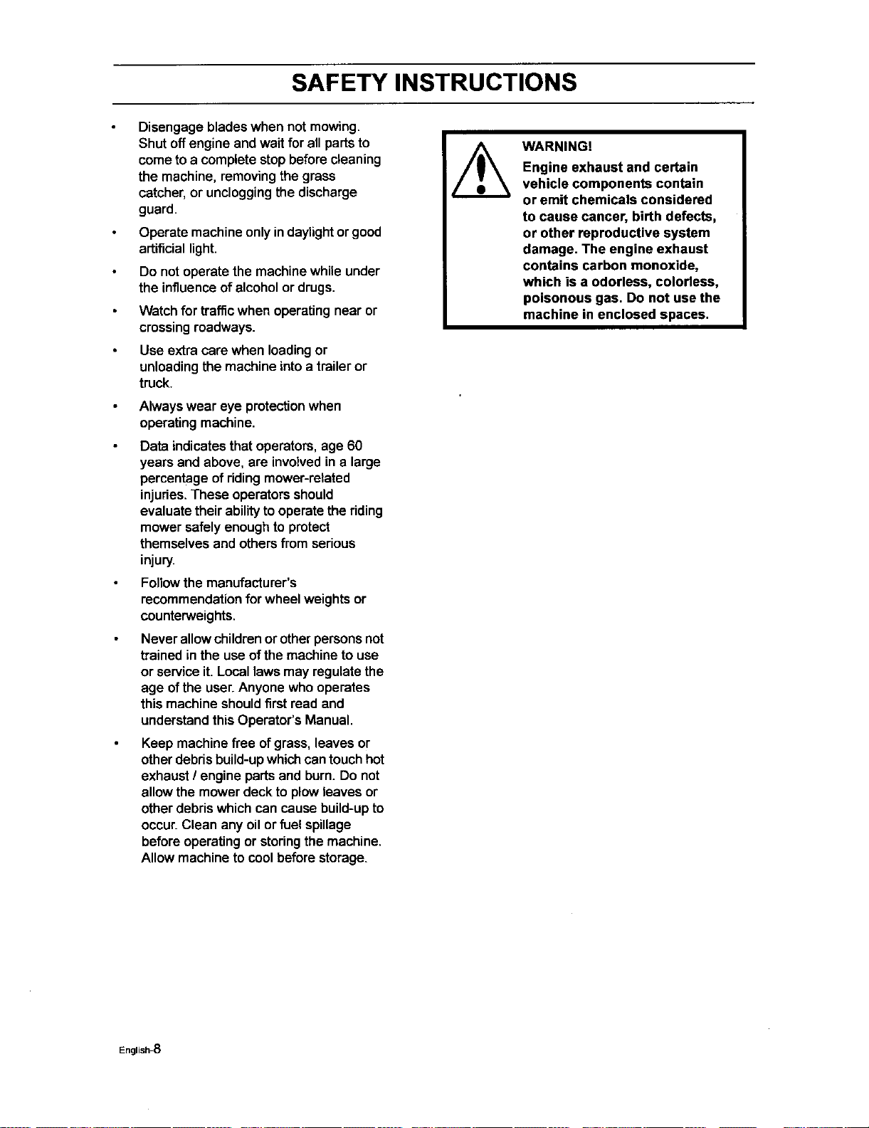
Make sure that you have firstaid equipment
close at handwhen usingthe machine.
Never use the machinewhen barefoot.
Always wear protectiveshoes or boots,
preferablywith steeltoecaps.
Always wear approved protectiveglasses
or a full visorwhen assemblingor driving.
Always wear gloveswhen handlingthe
blades.
Never wear looseclothingthatcan get caught
in movingparts.
Use ear protectorsto avoid damage to
hearing.
%
B011_70
Personalprotectiveequipment
Slope Operation
Slopes are a majorfactor related to lossof
controland tip-over accidents,whichcan
resultin severe injuryor death. Operationon
all slopesrequiresextra caution, If you
cannot back upthe slopeor ifyoufeel uneasy
on it, do not mow it.
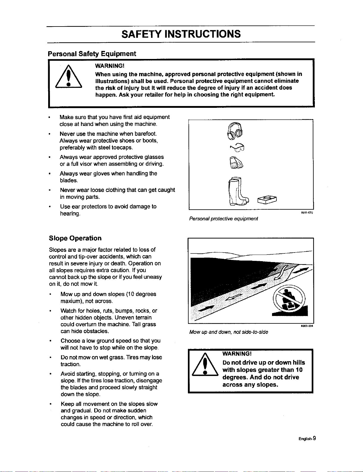
Mow up and downslopes (10 degrees
maxium), notacross.
Watch for holes, ruts, bumps, recks,or
other hiddenobjects. Uneven terrain
could overturnthe machine.Tall grass
can hideobstacles.
Choose a low groundspeed so that you
will not have to stop while onthe slope.
Do notmow onwet grass. Tiresmay lose
traction.
Avoid starting,stopping,or turningon a
slope. Ifthe tireslosetraction,disengage
the blades and proceed slowlystraight
downthe slope.
Keep all movement on the slopesslow
and gradual. Do not make sudden
changes in speed or direction,which
could cause the machine to rollover.
Mow up and down, not side-to-side
60C_004
WARNING!
Do not drive up or down hills
with slopes greater than 10
degrees. And do not drive
across any slopes.
English-9
SAFETY INSTRUCTIONS
Use extra care while operating machine
withgrass catchersor otherattachments;
they can affectthe stabilityofthe
machine. Do not use on steepslopes.
Do nottry to stabilizethe machineby
putting your foot on the ground.
Do not mow near drop-offs, ditches, or
embankments. The machinecould
suddenlyroll over ifa wheel isover the
edge or ifthe edge caves in.
Children
Tragic accidentscan occurifthe operatoris
not alert tothe presence ofchildren.Children
are often attracted tothe machineand the
mowing activity.Never assume that children
willremainwhere you last saw them.
Keep childrenout ofthe mowing area
and inthe watchfulcare of a responsible
adult otherthan the operator.
Be alert and turn machineoff ifa child
enters the area.
Beforeand whilebacking, lookbehind
and down for smallchildren.
Never carry children, even with the
blades shutoff. They may fall offand be
seriouslyinjuredor interfere with safe
machine operation.Childrenwho have
been givenrides inthe pastmay
suddenlyappear in the mowing area for
another ride and be run over or backed
over by the machine.
Never allow childrento operate the
machine.
Use extra care when approachingblind
corners,shrubs,trees, or other objects
that may block yourview of a child.
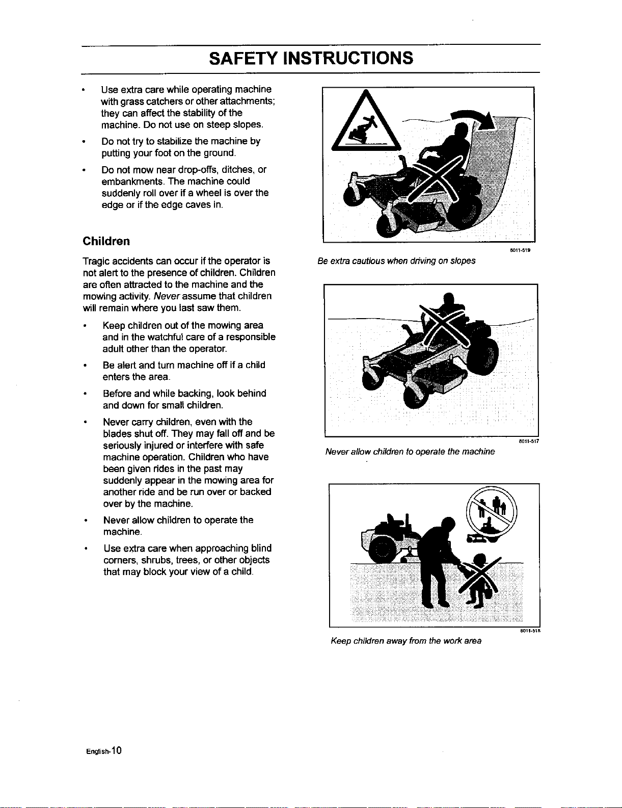
8011-519
Be extra cautious whendriving on slopes
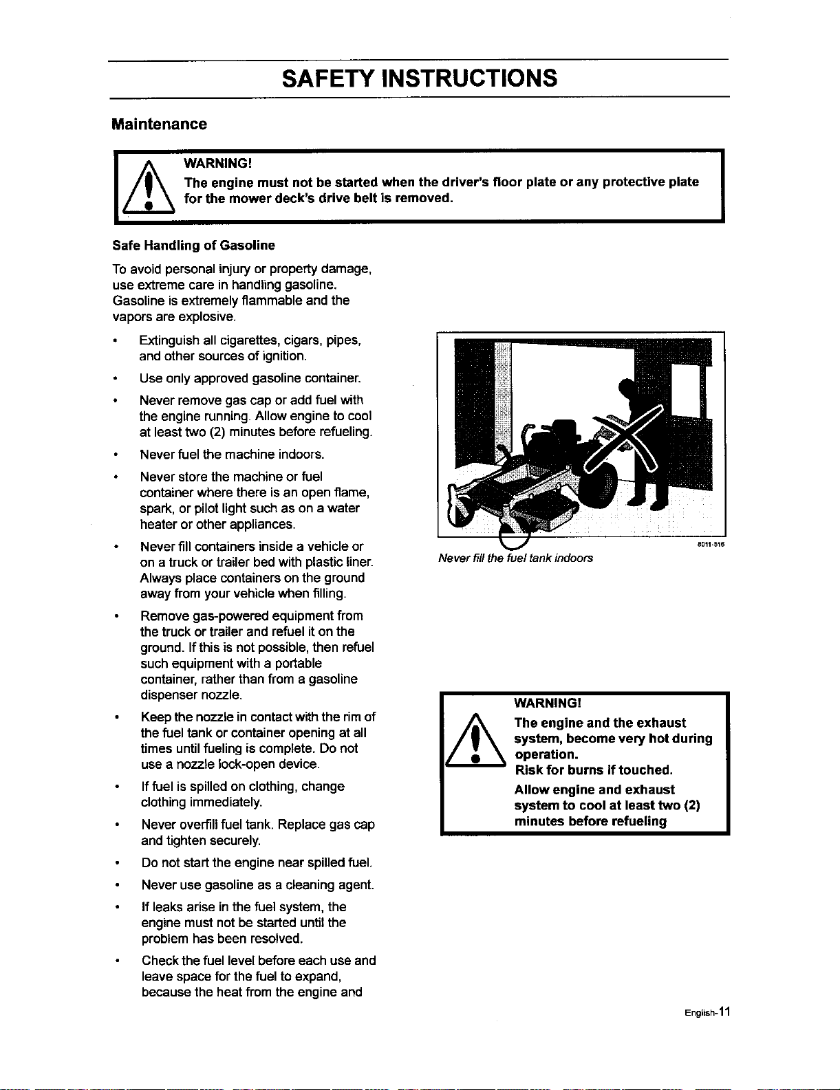
8011_517
Neverallowchildrentooperatethemachine
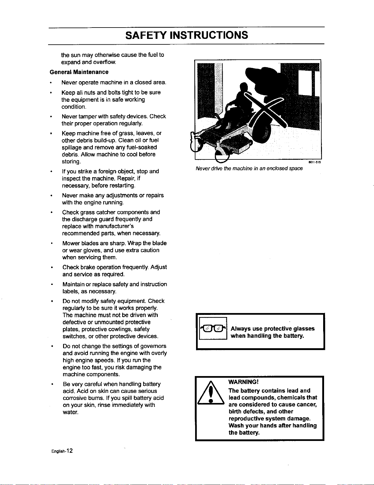
Keep children away from the work area
coil-st8
English-10
SAFETY INSTRUCTIONS
Maintenance
WARNING!
The engine must not be started when the driver's floor plate or any protective plate
for the mower deck's drive belt is removed,
Safe Handling of Gasoline
To avoid personalinjuryor propertydamage,
use extreme care in handlinggasoline.
Gasoline isextremely flammable and the
vapors are explosive.
Extinguishall cigarettes,cigars, pipes,
and other sourcesofignition.
Use only approvedgasolinecontainer.
Never remove gas cap or add fuel with
the engine running.Allowengine to cool
at leasttwo (2) minutesbeforerefueling.
Never fuel the machine indoors.
Never store the machine or fuel
containerwhere there isan open flame,
spark, or pilotlightsuch as on a water
heater or other appliances.
Never fillcontainersinsidea vehicleor
on a truck or trailer bed with plasticliner.
Always place containerson the ground
away from yourvehiclewhen filling.
Remove gas-powered equipmentfrom
the truck or trailer and refueliton the
ground.Ifthis isnot possible,then refuel
suchequipment with a portable
container,ratherthan from a gasoline
dispensernozzle.
Keep the nozzle in contactwiththe rimof
the fuel tank or containeropening at all
times untilfuelingis complete. Do not
use a nozzle lock-opendevice.
Iffuel is spilledon clothing,change
clothingimmediately.
Never overfillfuel tank. Replace gas cap
and tighten securely.
Do not startthe engine near spilledfuel.
Never use gasolineas a cleaning agent.
If leaksarise inthe fuel system,the
engine mustnot be started untilthe
problemhas been resolved.
Check thefuel level before each useand
leave space forthe fuel to expand,
because the heat from the engine and
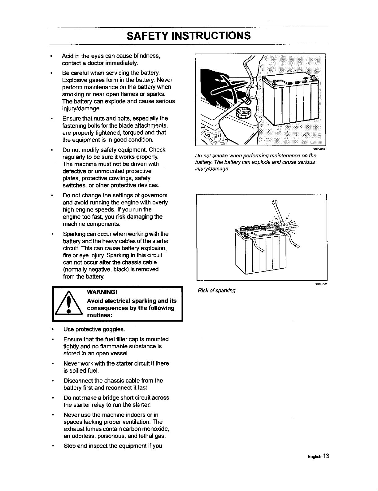
Never fill the fuel tank indoors
WARNING!
The engine and the exhaust
system, become very hot during
operation.
Risk for burns if touched.
Allow engine and exhaust
system to cool at least two (2)
minutes before refueling
I
English-11
SAFETY INSTRUCTIONS
the sun may otherwise cause the fuel to
expand and overflow.
General Maintenance
Never operate machine in a closed area.
Keep all nuts and boltstightto be sure
the equipmentis in safe working
condition.
Never tamperwith safety devices.Check
their properoperationregularly.
Keep machinefree of grass, leaves, or
other debris build-up. Clean oil or fuel
spillage and remove any fuel-soaked
debris. Allow machine to cool before
storing.
If you strike a foreign object, stop and
inspectthe machine. Repair, if
necessary,before restarting.
Never make any adjustmentsor repairs
withthe engine running.
Check grass catcher components and
the discharge guard frequently and
replace with manufacturer's
recommended parts,when necessary.
Mower blades are sharp. Wrap the blade
or wear gloves, and usa extra caution
when servicingthem.
Check brake operationfrequently. Adjust
and service as required.
Maintainorreplace safety and instruction
labels, as necessary.
Do not modify safetyequipment. Check
regularlyto be sure itworks properly.
The machine mustnot be drivenwith
defective or unmountedprotective
plates, protectivecowlings, safety
switches,or other protectivedevices.
Do not change the settingsof governors
and avoidrunning the engine with ovedy
high engine speeds. If you run the
engine too fast, you risk damaging the
machine components.
Be verycarefulwhen handlingbattery
acid. Acidon skincan cause serious
corrosive bums. If you spillbattery acid
on your skin,rinse immediatelywith
water.
Never drive the machine in an enclosedspace
Always use protective glasses
when handling the battery.
WARNING!
The battery contains lead and
lead compounds, chemicals that
are considered to cause cancer,
birth defects, and other
reproductive system damage.
Wash your hands after handling
the battery.
I
English-12
SAFETY INSTRUCTIONS
Acid in the eyes can cause blindness,
contact a doctor immediately.
Be careful when servicingthe battery.
Explosive gasesform in the battery. Never
perform maintenance on the battery when
smoking or near open flames or sparks.
The battery can explode and cause serious
injury/damage.
Ensure that nutsand bolts, especiallythe
fastening bolts for the blade attachments,
are propedy tightened, torqued and that
the equipment is in good condition.
Do not modify safety equipment. Check
regulady to be sure itworks properly.
The machine must not be driven with
defective or unmounted protective
plates, protective cowlings, safety
switches, or other protective devices.
Do not change the settingsof governors
and avoid runningthe engine with ovedy
high engine speeds. Ifyou runthe
engine too fast, you risk damagingthe
machine components.
Sparkingcan occurwhen workingwith the
battery and the heavycables ofthe starter
circuit.This can cause batteryexplosion,
fire or eye injury.Sparkinginthis circuit
can not occurafterthe chassiscable
(normallynegative,black)isremoved
fi'om the battery.
I_ ARNING!
Avoid electrical sparking and its
consequences by the following
routines:
Use protectivegoggles.
Ensure thatthe fuel filler cap ismounted
tightlyand noflammable substanceis
storedin an openvessel.
Never work with thestarter circuitifthere
is spilledfuel.
Disconnectthe chassis cable fTomthe
battery firstand reconnectit last.
Do notmake a bridgeshortcircuitacross
the starter relay to runthe starter.
Never use the machineindoorsor in
spaces lacking properventilation.The
exhaustfumes containcarbon monoxide,
an ododess, poisonous,and lethalgas.
Stopand inspectthe equipmentifyou
6003_09
Donotsmokewhenperformingmaintenanceonthe
battery Thebatterycanexplodeandcauseserious
injury/damage
I
Risk of sparking
800_7Z8
English-13
SAFETY INSTRUCTIONS
run over or intoanything. If necessary,
make repairs before starting.
Never make adjustments with the engine
running.
The machine istested and approved only
with the equipmentoriginally provided or
recommended by the manufacturer. Only
use approved repairpartsfor the
machine.
The blades are sharpand can cause
cutsand gashes. Wrap theblades oruse
protectivegloveswhen handlingthem.
Check the parkingbrake's functionality
regularly.Adjust and serviceas
necessary.
The mulchblades shouldonlybe used in
familiar areas when higherquality
mowingis desired.
Reduce the riskoffire by removing
grass, leaves, and otherdebris that may
have accumulatedonthe machine.Allow
the machineto cool beforeputtingitin
storage.
Regularlyclean deckand undersideof
deck, avoidsprayingengine and
electdcal componentswithwater.
Transport
The machine isheavy and can cause
sedouscrushinginjuries.Be extra
cautiouswhen it isloaded on or
unloaded froma vehicle or trailer.
Use an approved trailer to transportthe
machine.Activate the parking brake, turn
offthe fuel supply,and fasten the
machinewith approved fastening
devices, such as bands, chains,or
straps,when transporting.
Do not operate this machineon public
roadways.
Check and abide by localtraffic
regulations before transporting the
machine on any road.
Do not tow this machine, it may cause
damage to the drive system.
Do nottow any trailers,etc. withthis
mower.They may jackknifeor overtum
causingdamage to the mower and
possiblyseriousinjurytothe operator.
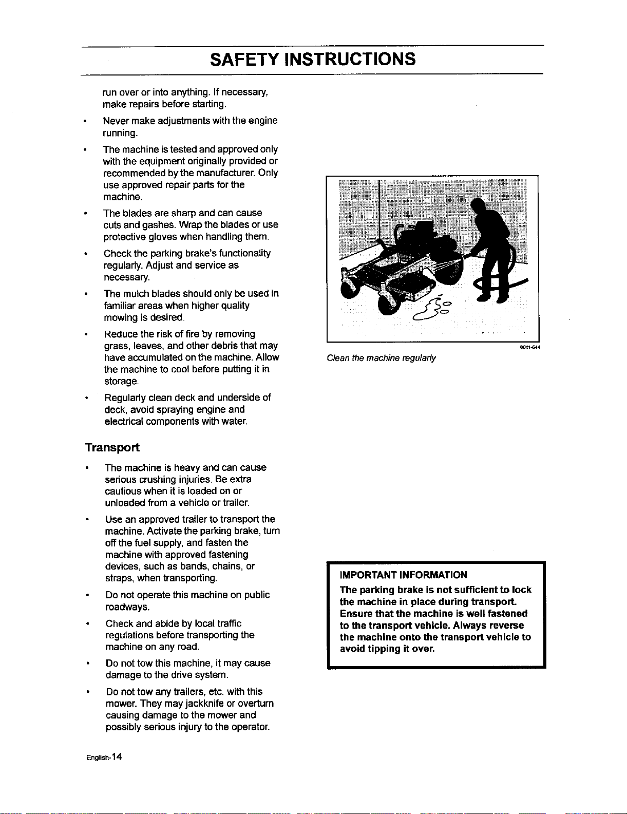
C/ean the machine regularly
80_1_44
IMPORTANT INFORMATION
The parking brake is not sufficient to lock
the machine in place during transport.
Ensure that the machine iswell fastened
to the transport vehicle. Always reverse
the machine onto the transport vehicle to
avoid tipping it over.
English-14
SAFETY INSTRUCTIONS
Customer responsibilities
Read and observethe safety rules.
Follow a regular schedule in maintaining,
caring for and using your mower.
Follow the instructions under
"Maintenance" and "Storage" sections of
this owner's manual.
This machinehas no brain• Use yours!
WARNING!
This mower is equipped with an internal combustion engine and should not be
used on or near any unimproved forest-covered, bush-covered or grass-covered
land unless the engine's exhaust system is equipped with a spark arrester
meeting applicable local or state laws (if any). If a spark arrester is used, it should
be maintained in effective working order by the operator.
A spark arrester for the muffleris available through your authodzed Husqvama dealer.
English-15
CONTROLS
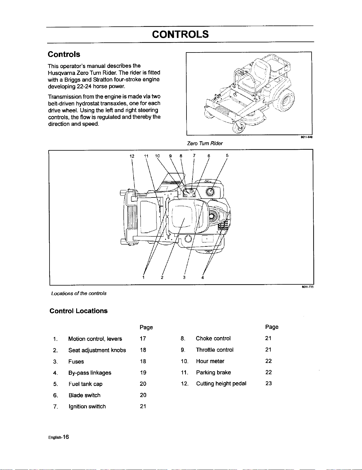
Controls
This operator'smanual describes the
HusqvarnaZero Turn Rider.The rider isfitted
with a Briggs and Stratton four-stroke engine
developing 22-24 horse power.
Transmissionfrom the engine is madeviatwo
belt-driven hydrostat transaxles, one for each
drive wheel. Using the lef_and right steering
controls, the flow is regulated and thereby the
direction and speed.
Zero Turn Rider
12 11 10 9 8 7 6 5
801t_48
1 2 3 4
Locationsof the controls
8011735
Control Locations
1. Motioncontrol, levers
2. Seat adjustment knobs
3. Fuses
4. By-pass linkages
5. Fueltank cap
6. Bladeswitch
7. Ignition swittch
Page
17
18
18
19
20
20
21
8. Choke control
9. Throttlecontrol
10. Hour meter
11. Parking brake
12. Cuttingheight pedal
Page
21
21
22
22
23
English-16
CONTROLS
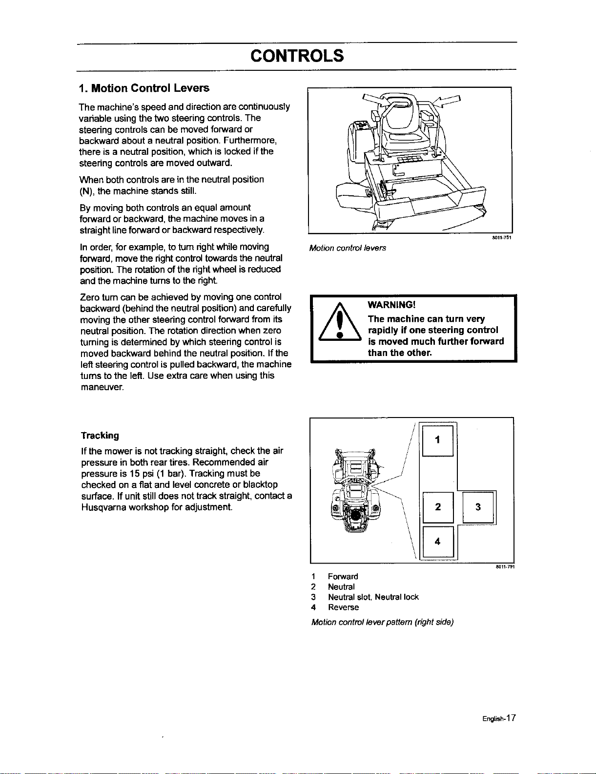
t. Motion Control Levers
The machine's speed and direction are continuously
variable usingthe two steeringcontrols. The
steeringcontrolscan be moved forwardor
backwardabout a neutral position.Furthermore,
there is a neutral position,which islocked ifthe
steedng controls are moved outward.
When both controlsare in the neutral position
(N), the machine stands still.
By movingboth controlsan equal amount
forward or backward, the machine movesina
straight line forward or backward respectively.
In order,for example, toturndght whilemoving
forward, move the dght controltowards the neutral
position.The rotationofthe dght wheel isreduced
and themachineturnsto the dght.
Zero turncan be achieved by moving one control
backward (behind the neutral position) and carefully
moving the other steering control forward from its
neutral position. The rotation direction when zero
turning is determined by which steering control is
moved backward behind the neutral position. If the
left steering control is pulled backward, the machine
turns to the left. Use extra care when using this
maneuver
Motion control levers
8011351
WARNING!
The machine can turn very
rapidly if one steering control
is moved much further forward
than the other,
Tracking
If the mower is nottrackingstraight,check the air
pressure in bothrear tires. Recommended air
pressure is 15 psi (1 bar). Tracking must be
checked on a flat and level concrete or blacktop
surface. If unit still does not track straight, contact a
Husqvarna workshop for adjustment.
2 3
4
1 Forward
2 Neutral
3 Neutral slot, Neutral lock
4 Reverse
Motion controlleverpattem (rightside)
8011 791
English-17
CONTROLS
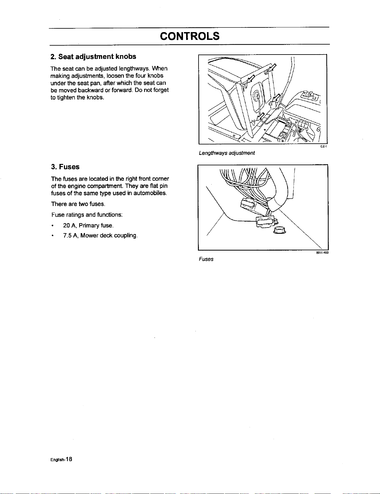
2. Seat adjustment knobs
The seat can be adjusted lengthways. When
making adjustments,loosen the four knobs
under the seat pan, after which the seat can
be moved backward or forward. Do not forget
to tighten the knobs.
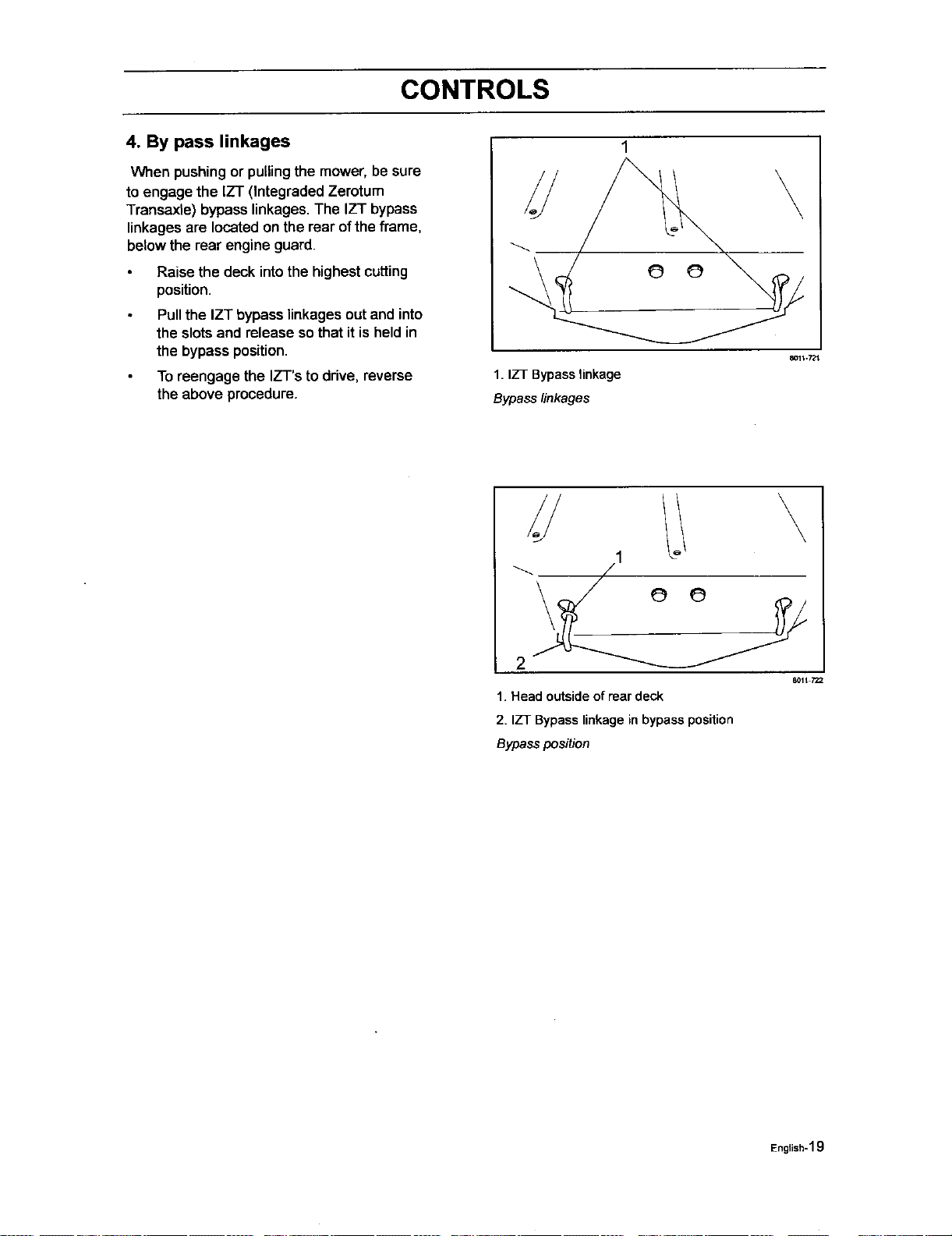
3. Fuses
The fusesare located in the rightfront corner
ofthe engine compartment.They are fiatpin
fuses ofthe same type used in automobiles.
There are two fuses.
Fuse ratings and functions:
20 A, Primary fuse.
7.5 A, Mower deck coupling.
CZ1
Lengthwaysadjustment
Fuses
8011 J_3
English-18
CONTROLS
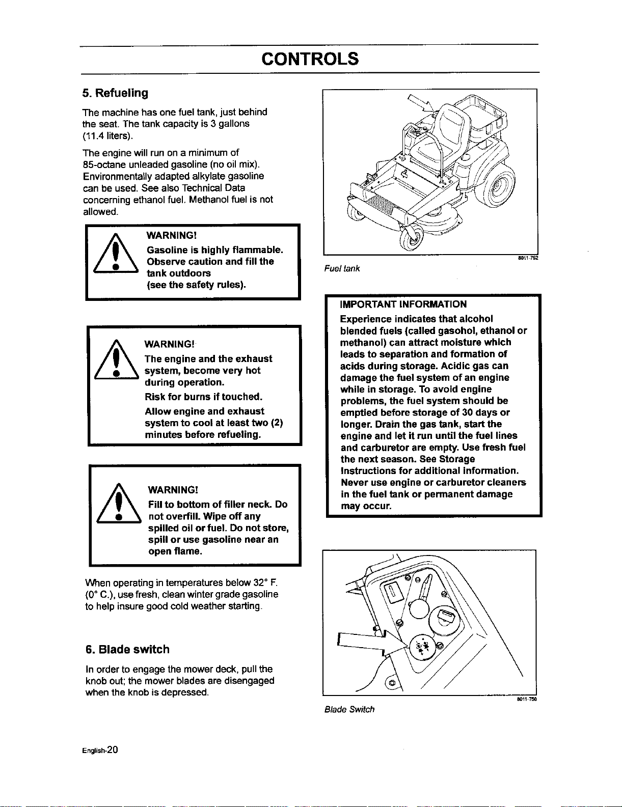
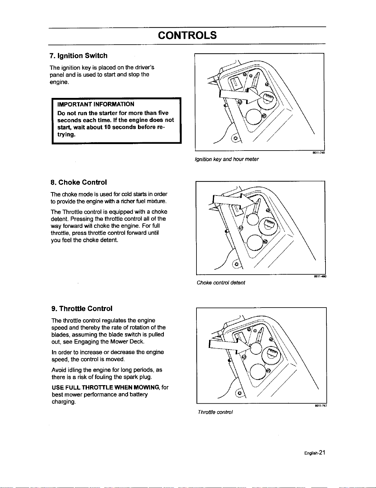
4. By pass linkages
When pushing or pulling the mower, be sure
toengage the IZT (Integraded Zerotum
Transaxle) bypass linkages.The IZT bypass
linkages are locatedon the rear ofthe frame,
belowthe rear engine guard.
Raise the deck intothe highest cutting
position.
Pull the IZT bypass linkages out and into
the slotsand release sothat it isheld in
the bypass position.
To reengage the IZ'l"sto drive, reverse
the above procedure.
1. IZT Bypass linkage
Bypass linkages
\
8011-721
\
2
1.Headoutsideofreardeck
2. IZTBypasslinkageinbypassposition
Bypassposition
801t 722
English-1 g
CONTROLS
5. Refueling
The machine has one fuel tank, just behind
the seat. The tank capacity is 3 gallons
(11.4 liters).
The engine will run on a minimum of
85-octane unleaded gasoline (no oil mix).
Environmentally adapted alkylate gasoline
can be used. See also Technical Data
concerning ethanol fuel. Methanol fuel is not
allowed.
WARNING!
Gasoline is highly flammable.
Observe caution and fill the
tank outdoors
(see the safety rules).
WARNING!
The engine and the exhaust
system, become very hot
during operation.
Risk for burns if touched.
Allow engine and exhaust
system to cool at least two (2)
minutes before refueling.
WARNING!
Fill to bottom of filler neck. Do
not overfill. Wipe off any
spilled oil or fuel. Do not store,
spill or use gasoline near an
open flame.
When operating in temperatures below 32° F.
(0° C.), use fresh, clean wintergradegasoline
to help insure goodcoldweather starting.
6. Blade switch
In order to engage the mower deck, pullthe
knob out; the mower blades are disengaged
when the knob isdepressed.
Fuel tank
_117_
IMPORTANT INFORMATION
Experience indicates that alcohol
blended fuels (called gasohol, ethanol or
methanol) can attract moisture which
leads to separation and formation of
acids during storage. Acidic gas can
damage the fuel system of an engine
while in storage. To avoid engine
problems, the fuel system should be
emptied before storage of 30 days or
longer. Drain the gas tank, start the
engine and let it run until the fuel lines
and carburetor are empty. Use fresh fuel
the next season. See Storage
Instructions for additional information.
Never use engine or carburetor cleaners
in the fuel tank or permanent damage
may occur.
Blade Switch
_117_
English-20
CONTROLS
7. Ignition Switch
The ignitionkey isplaced on the driver's
paneland is used tostart and stopthe
engine.
IMPORTANT INFORMATION
Do not run the starter for more than five
seconds each time. If the engine does not
start, wait about 10 seconds before re-
trying.
Ignition key and hour meter
11011.748
8. Choke Control
The choke mode isused for coldstartsin order
toprovidethe enginewitha richerfuel mixture.
The Throttlecontrolis equippedwith a choke
detent. Pressing thethrottle controlall ofthe
way forward willchoke the engine. Forfull
throttle,press throttlecontrolforward until
you feel the choke detent.
Choke control detent
8011480
9. Throttle Control
The throttle controlregulates the engine
speed and thereby the rate ofrotation ofthe
blades, assumingthe blade switchis pulled
out, see Engaging the Mower Deck.
In order to increaseor decrease the engine
speed, the controlis moved.
Avoid idlingthe engine for long periods, as
there is a risk offouling the spark plug.
USE FULL THROTTLE WHEN MOWING, for
best mower performance and battery
charging.
Throttlecontrol
8011 747
English-21
CONTROLS
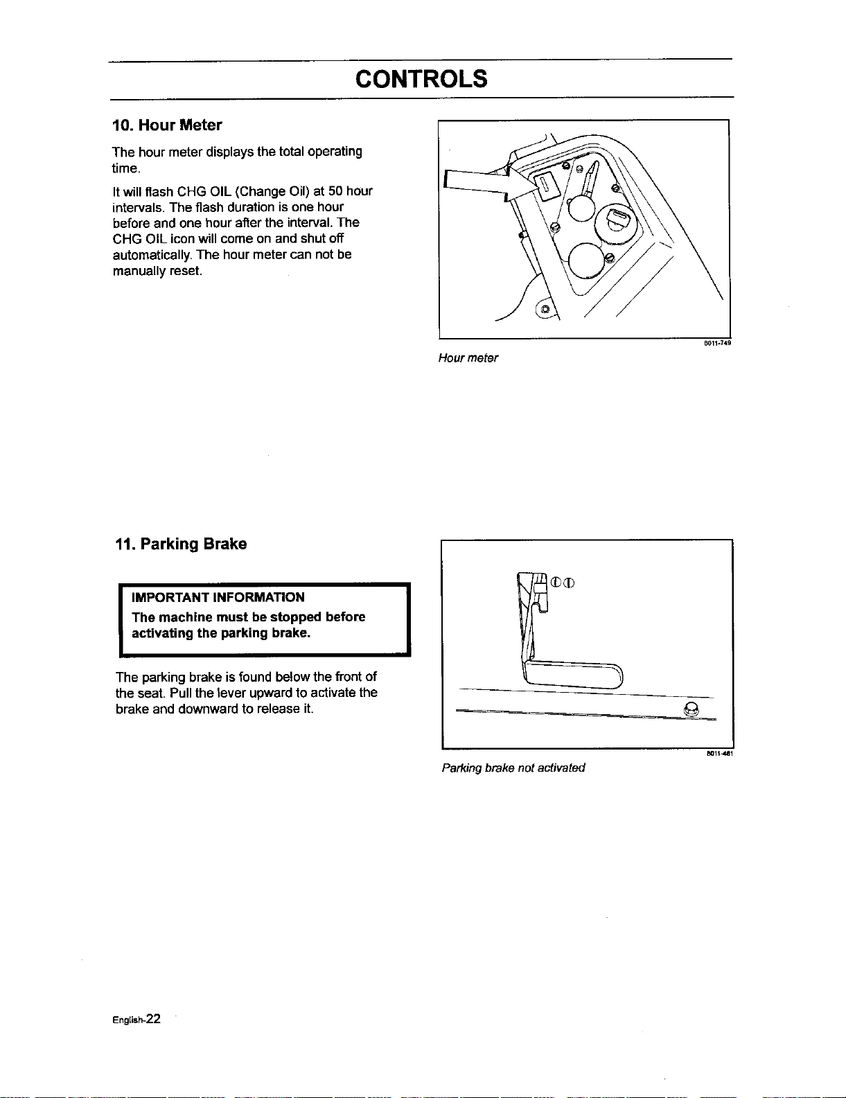
10. Hour Meter
The hour meter displaysthe total operating
time.
Itwillflash CHG OIL (Change Oil) at 50 hour
intervals.The flash duration isone hour
before and one hour after the interval. The
CHG OIL icon will come on and shut off
automatically. The hour meter can not be
manually reset.
Hour meter
B011=749
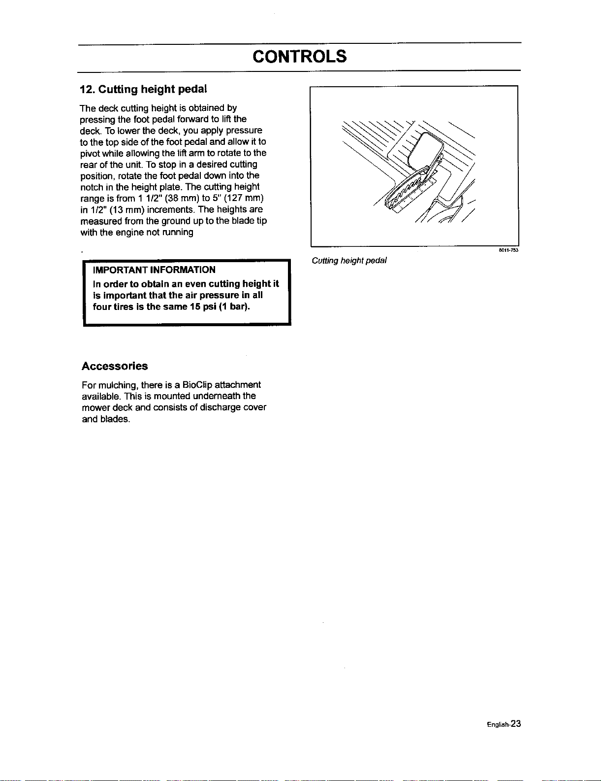
11. Parking Brake
I
IMPORTANT INFORMATION
The machine must be stopped before
activating the parking brake.
I
The parking brake is found be!ow the front of
the seat. Pull the lever upward to activate the
brake and downward to release it.
Parking brake not activated
English-22
CONTROLS
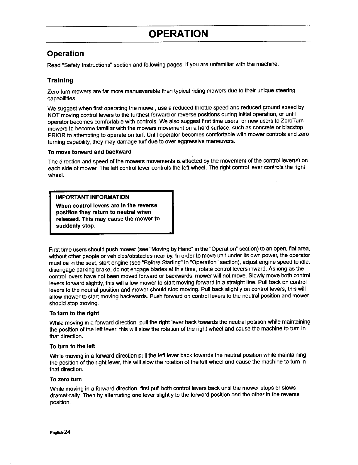
12. Cutting height pedal
The deck cuttingheight isobtained by
pressing the foot pedal forward to lif_the
deck. To lower the deck, you apply pressure
to the top side of the foot pedal and allow it to
pivot while allowing the liftarm to rotate to the
rear of the unit. To stop in e desired cutting
position, rotate the foot pedal down into the
notch in the height plate. The cutting height
range is from 1 1/2" (38 ram) to 5" (127 mm)
in 1/2" (13 mm) increments. The heights are
measured from the ground up to the blade tip
with the engine not running
I MPORTANT INFORMATION
In order to obtain an even cutting height it
is important that the air pressure in all
four tires is the same 15 psi (1 bar).
Cutting height pedal
_011-753
Accessories
For mulching, there is a BioClipattachment
available. This is mounted undemeath the
mower deck and consists of discharge cover
and blades.
English-23
OPERATION
Operation
Read "Safety Instructions"sectionand followingpages, ifyou are unfamiliarwith the machine.
Training
Zero tum mowers are far more manueverablethan typical riding mowers due to their uniquesteering
capabilities.
We suggestwhen firstoperatingthe mower,use a reduced throttlespeed and reduced groundspeed by
NOT movingcontrollevers to thefurthest forwardor reverse positionsduring initialoperation,or until
operatorbecomes comfortablewith controls.We also suggestfirsttime users,or new usersto ZeroTum
mowers to become familiar with the mowers movementon a hardsurface, suchas concreteor blacktop
PRIOR to attemptingtooperate on turf.Until operatorbecomes comfortable with mower controlsand zero
turningcapability,they may damage turfdue toover aggressivemaneuvers.
To move forward and backward
The direction and speed ofthe mowers movements iseffected by the movement of the control lever(s) on
each side of mower.The leftcontrollever controlsthe leRwheel. The rightcontrollever controls the right
wheel.
IMPORTANT INFORMATION
When control levers are in the reverse
position they return to neutral when
released, This may cause the mower to
suddenly stop.
Firsttime users shouldpush mower (see "Moving by Hand" inthe "Operation" section)to an open, fiatarea,
withoutotherpeople orvehicles/obstaclesnear by. In order tomove unitunder itsown power,the operator
mustbe inthe seat, startengine (see "Before Starting"in "Operation" section), adjustengine speed toidle,
disengage parkingbrake, do not engage bladesat this time, rotate controllevers inward.As long as the
control levers have not been moved forward or backwards, mowerwillnot move. Slowlymovebothcontrol
levers forward slightly,thiswillallow mowerto startmovingforward in a straightline. Pull back on control
leversto the neutral positionand mower shouldstop moving.Pullback slightlyon control levers,thiswill
allowmower to startmoving backwards.Push forward on control levers to the neutral positionand mower
shouldstop moving.
To turn to the right
While moving in a forward direction, pullthe right lever back towards the neutralpositionwhile maintaining
the positionofthe leftlever, thiswillslow the rotationofthe rightwheel and cause the machineto turn in
that direction.
To turn to the left
While moving in a forward direction pullthe left lever back towardsthe neutral position while maintaining
the position of the right lever, this will slow the rotation of the left wheel and cause the machine to turn in
that direction.
To zero turn
While moving in a forward direction,firstpull bothcontrol levers back untilthe mower stopsor slows
dramatically.Then by alternatingone lever slightlytothe forward positionand the otherin the reverse
position.
English*24
OPERATION
Before Starting
Read the sectionsSafety Instructions
and Controls before startingthe
machine.
Perform the dailymaintenance before
starting(see Maintenance Schedule
in the Maintenance section).
Check that there is sufficient fuel in the
fuel tank.
Adjust the seat to the desired position.
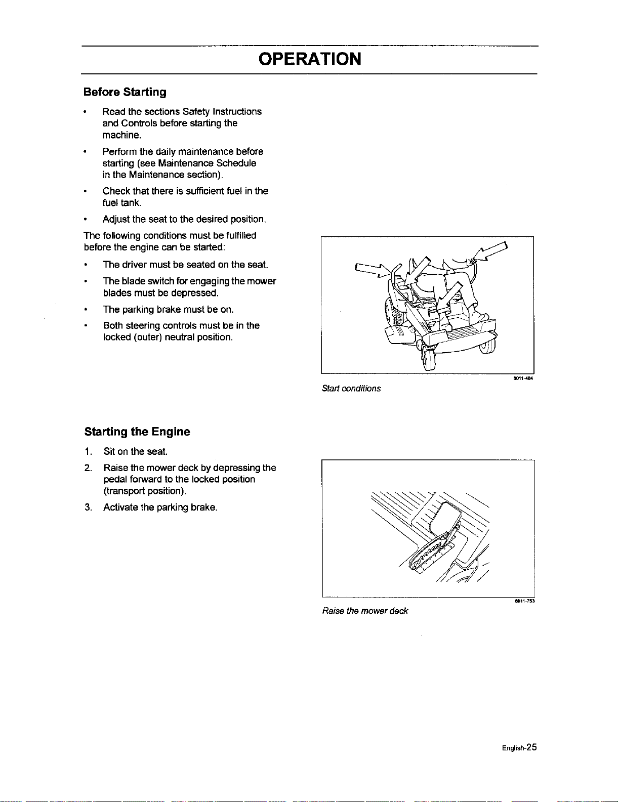
The following conditions mustbe fulfilled
before the engine can be started:
The driver must be seated on the seat.
The blade switchfor engaging the mower
blades must be depressed.
The parkingbrake mustbe on.
Bothsteeringcontrolsmust be in the
locked(outer) neutral position.
Startconditions
_1_484
Starting the Engine
1. Sit on the seat.
2. Raise the mower deckbydepressingthe
pedal forwardto the lockedposition
(transportposition).
3. Activate the parkingbrake.
Raise the mower deck
8Or1 753
Engtish-25
OPERATION
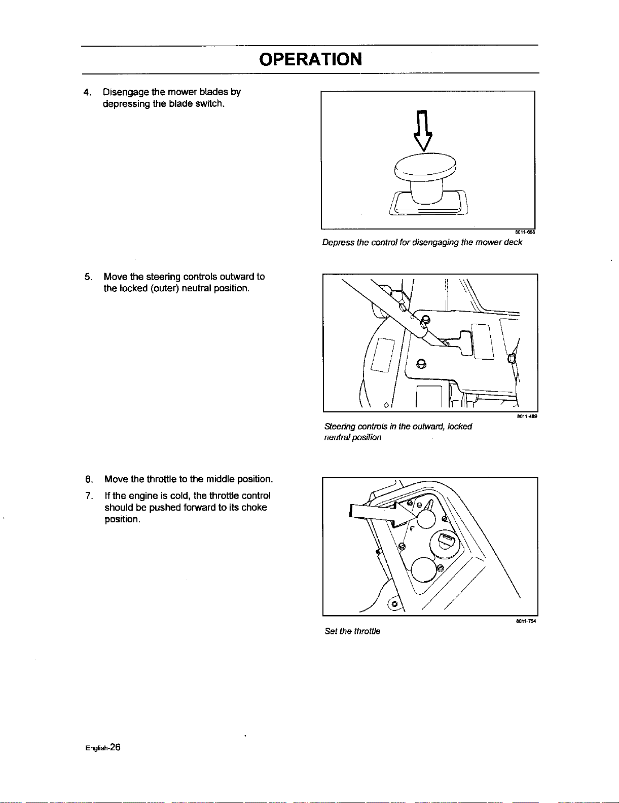
4.
Disengage the mower blades by
depressing the blade switch.
6Q11_68
Depressthecontrolfordisengagingthemowerdeck
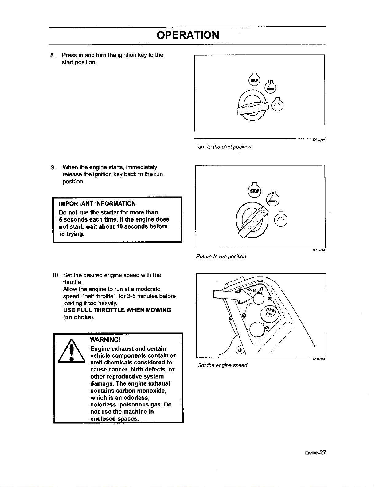
5. Move the steedng controls outward to
the locked (outer) neutral position.
Steedng controlsin the outward, locked
neutral position
8011489
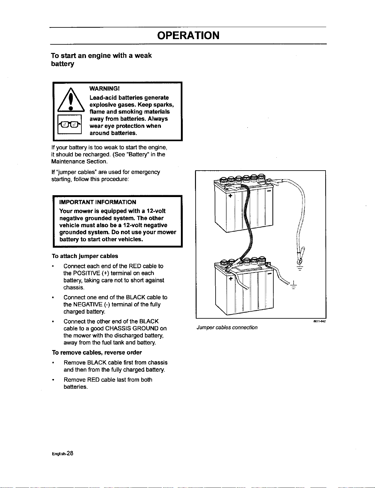
6.
7.
Move the throttle to the middle position.
Ifthe engine is cold,the throttle control
shouldbe pushed forward to itschoke
position.
Set the throttle
80_1754
English-26
OPERATION
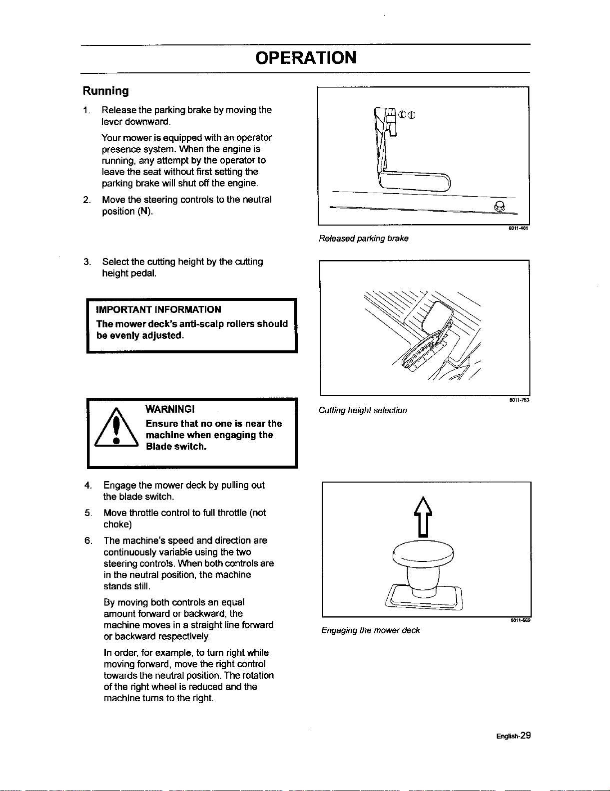
8.
Press in and turn the ignition key to the
startposition.
801_.742
Turntothestartposition
9.
When the engine starts,immediately
release the ignitionkey back to the run
position.
IMPORTANT INFORMATION
Do not run the starter for more than
5 seconds each time. if the engine does
not start, wait about 10 seconds before
re-trying.
aO11-743
Returntorunposition
10. Set the desired engine speed with the
throttle.
Allow the engine to run at a moderate
speed, "half throttle",for 3-5 minutesbefore
loadingittoo heavily.
USE FULL THROTTLE WHEN MOWING
(no choke).
WARNING!
Engine exhaust and certain
vehicle components contain or
emit chemicals considered to
cause cancer, birth defects, or
other reproductive system
damage. The engine exhaust
contains carbon monoxide,
which is an odorless,
colorless, poisonous gas. Do
not use the machine in
enclosed spaces.
Set the engine speed
8011754
English-27
OPERATION
To start an engine with a weak
battery
WARNING!
Lead-acid batteries generate
explosive gases. Keep sparks,
flame and smoking materials
away from batteries. Always
wear eye protection when
around batteries.
Ifyour battery istoo weak tostartthe engine,
it shouldbe recharged. (See "Battery" in the
Maintenance Section.
If"jumper cables" are used for emergency
starting,follow this procedure:
IMPORTANT INFORMATION
Your mower is equipped with a 12-volt
negative grounded system. The other
vehicle must also be a 12-volt negative
grounded system. Do not use your mower
battery to start other vehicles.
To attach jumper cables
Connect each end ofthe RED cable to
the POSITIVE (+) terminal on each
battery,taking care notto shortagainst
chassis.
Connect one end of the BLACK cable to
the NEGATIVE (-) terminal of the fully
charged battery.
Connect the other end of the BLACK
cable to a good CHASSIS GROUND on
the mower with the discharged battery,
away from the fuel tank and battery.
To remove cables, reverse order
Remove BLACK cable firstfromchassis
and then from the fullycharged battery.
Remove RED cable lastfrom both
batteries.
Jumper cables connection
8011-642
English-28
OPERATION
Running
1. Release the parking brake by movingthe
lever downward.
2.
Yourmower isequippedwithan operator
presence system. When the engine is
running,any attemptbythe operatorto
leave the seat withoutfirst settingthe
parkingbrake willshutoffthe engine.
Move the steeringcontrolsto the neutral
position(N).
3. Select the cuttingheight by the cutting
height pedal.
I
IMPORTANT INFORMATION
The mower deck's anti-scalp rollers should
be evenly adjusted,
8011J_81
Releasedparkingbrake
I
WARNINGI
Ensure that no one is near the
machine when engaging the
Blade switch.
4.
5.
6.
Engage the mower deck by pullingout
the blade switch.
Move throttle controlto fullthrottle (not
choke)
The machine'sspeed and directionare
continuouslyvadable usingthe two
steeringcontrols.When bothcontrolsare
inthe neutral position,the machine
standsstill.
By moving bothcontrols an equal
amountforward or backward, the
machine moves in a straight line forward
or backward respectively.
In order, for example, to turn dght while
moving forward, move the right control
towards the neutral position. The rotation
of the dght wheel is reduced and the
machine turns to the right.
Cutting height selection
8011=753
Engaging the mower deck
English-29
OPERATION
Turning on the spotcan be achieved by
moving one controlbackward (behind
the neutral position) and carefully moving
the other steering control forward from its
neutral position.
Operating on hills
Read the Safety Instructions"Driving on
Slopes" inthe "Safety Instructions".
WARNING!
Do not drive up or down hills
with slopes greater than
10 degrees. And do not drive
across any slopes.
The slowestspeed possible shouldbe
used before startingup or down hills.
Avoid stoppingor changingspeed on
hills.
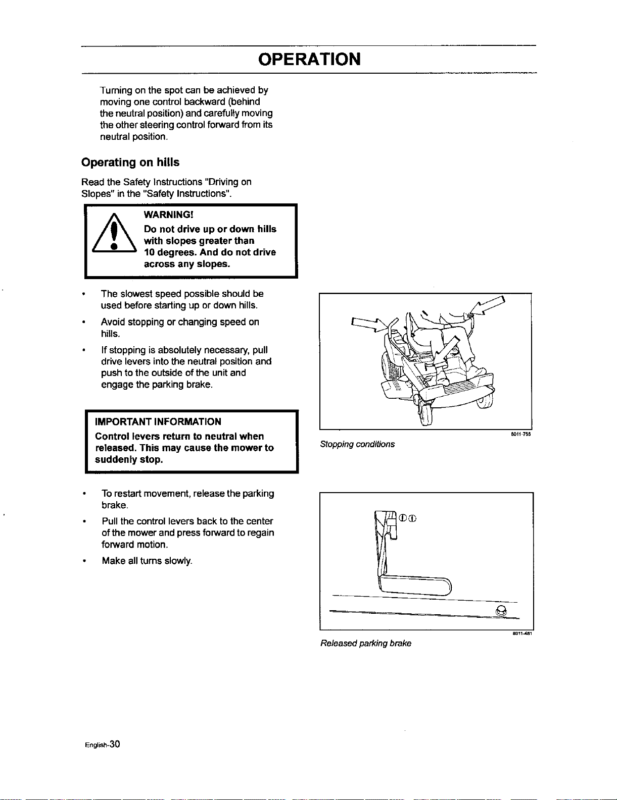
If stoppingisabsolutelynecessary, pull
drive levers into the neutral position and
pushtothe outsideofthe unitand
engage the parkingbrake.
I IMPORTANT INFORMATION
Control levers return to neutral when
released, This may cause the mower to
suddenly stop.
To restart movement, release the parking
brake.
Pull the control levers back to the center
ofthe mower and pressforward to regain
forward motion.
Make allturns slowly.
Stopping conditions
8011 755
Released parking brake
English-3O
OPERATION
Mowing Tips
Observe and flag rocks and otherfixed
objectsto avoid collisions.
Begin with a highcuttingheightand
reduce ituntilthe desired mowingresult
isattained.
The average lawn shouldbe cutto 2 1/2"
(64 mm) during thecool season and over
3" (76 mm) during the hot months.For
healthierand better lookinglawns, mow
often aftermoderate growth.
For best cuttingperformance,grass over
6" (15 cm) in heightshouldbe mowed
twice. Make the firstcut relativelyhigh;
the secondto the desired height.
The mowingresultwillbe bestwith a
high engine speed (the blades rotate
rapidly)and low speed (the rider moves
slowly). If the grass isnot too long and
dense, the ddving speed can be
increasedwithout negativelyaffecting
the mowingresult.
The finest lawnsare obtainedbymowing
often.The lawn becomesmore even and
the grass clippingsmore evenly
distributedoverthe mown area. The total
time taken isnot increased as a higher
operatingspeed can be used without
poor mowingresults.
Avoid mowingwet lawns. The mowing
resultis poorerbecause the wheels sink
intothe softlawn, clumpsbuild,and the
grass clippingsfasten underthe cowling.
Hose the mower deck undersidewith
water aftereach use. When cleaning,the
mower deckshall be raised intothe
transportposition.Make surethe mower
is cooled and the engine is off.
Use compressedair to clean top surface
of the deck. Avoid floodingwater on top
surface, engine and electdcal
components.
When the mulchingkitis used, itis
importantthat the mowing intervalis
frequent.
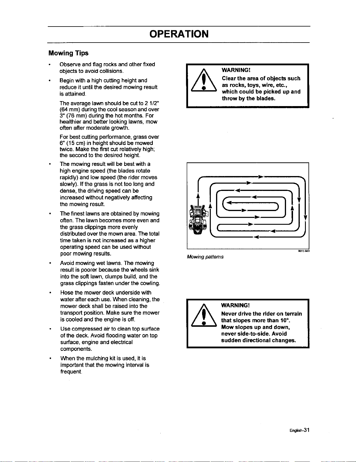
Mowing patterns
WARNING!
Clear the area of objects such
as rocks, toys, wire, etc.,
which could be picked up and
throw by the blades.
8011_03
WARNING!
Never drive the rider on terrain
that slopes more than 10°.
Mow slopes up and down,
never side-to-side. Avoid
sudden directional changes.
English*31
OPERATION
Stopping the Engine
Allow the engine to idle a minute in orderto
attain normal operating temperature before
stoppingit, ifit has been worked hard. Avoid
idlingthe engine for longerperiods, as there
is a riskofthe sparkplugsfouling.
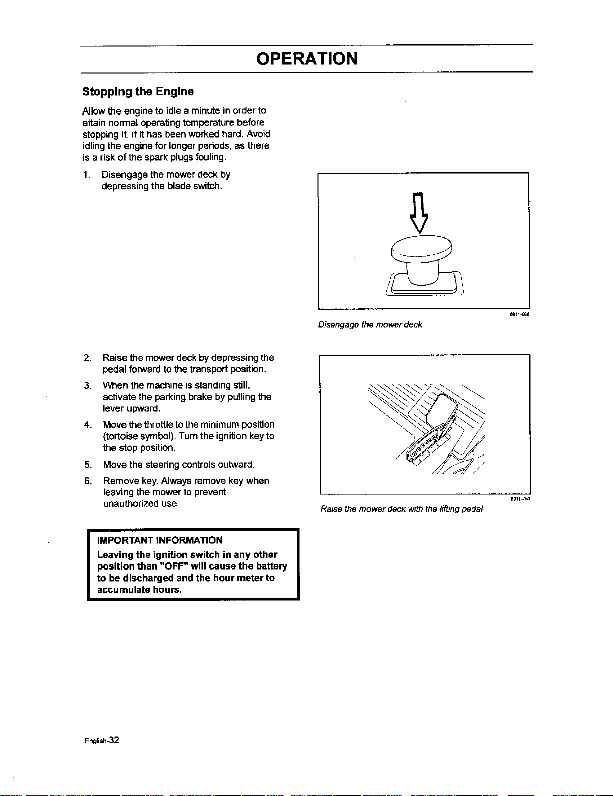
1. Disengage the mower deck by
depressing the blade switch.
80t1_
Disengagethemowerdeck
2. Raise the mower deck by depressing the
pedal forwardto the transportposition.
3. When the machine isstandingstill,
activatethe parkingbrake by pullingthe
lever upward.
4. Move thethrottletothe minimumposition
(tortoisesymbol).Turn the ignitionkeyto
the stop position.
5. Move the steeringcontrols outward.
6. Remove key. Always remove key when
leaving the mower to prevent
unauthorizeduse.
Raise the mower deck withthe lifting pedal
B011=753
IMPORTANT INFORMATION
Leaving the ignition switch in any other
position than "OFF" will cause the battery
to be discharged and the hour meter to
accumulate hours.
English-32
OPERATION
Moving by Hand
WARNING!
No adjustments or maintenance
to be carried out unless:
-the engine stopped,
-the ignition key has removed,
- the parking brake is on.
When pushingor pulling the mower,be sure
to engage the IZT (Integraded Zeroturn
Transaxle) bypass linkages.The IZ'I"bypass
linkages are locatedon the rear ofthe frame.
Raise the deck intothe highest cutting
position.
\
\
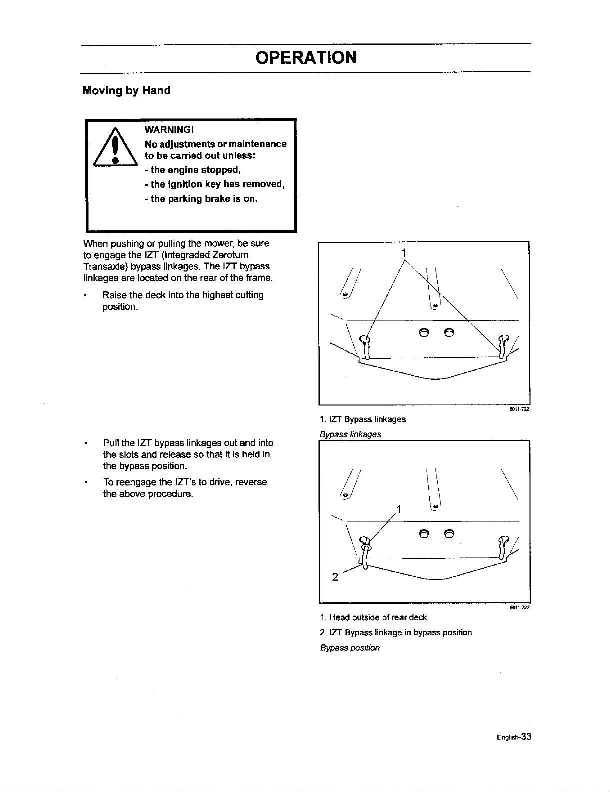
Pull the IZT bypass linkagesout and into
the slotsand release sothat itis held in
the bypass position.
To reengage the IZT's to ddve, reverse
the above procedure.
1. IZT Bypass linkages
Bypass linkages
80tl
.// \
1. Head outsideof rear deck
2. IZT Bypasslinkage in bypass position
Bypass position
8011 722
EnglJsh-33
MAINTENANCE
Maintenance
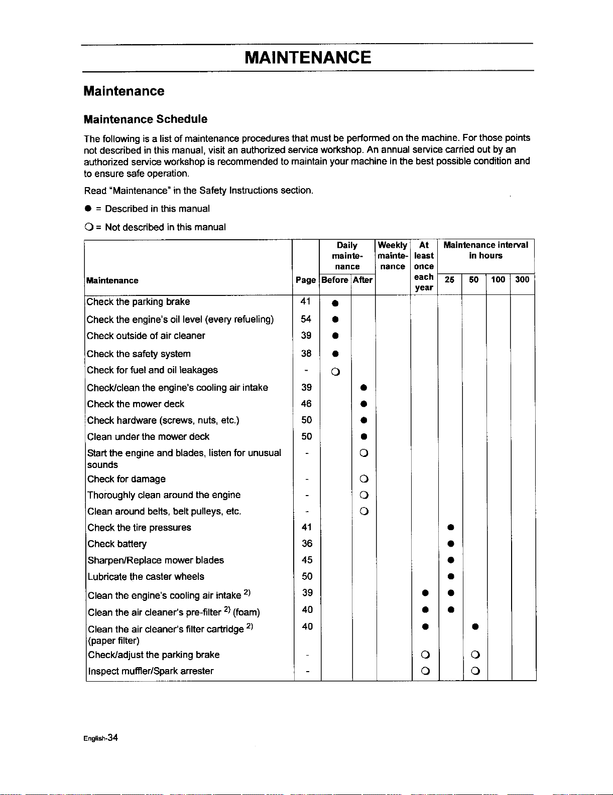
Maintenance Schedule
The following isa list of maintenance procedures that mustbe performed on the machine. Forthose points
not described in this manual, visit an authorized service workshop. An annual service carried out by an
authorized service workshop is recommended to maintain your machine in the best possible condition and
to ensure safe operation.
Read =Maintenance" in the Safety Instructionssection.
• = Described in this manual
C)= Not described in this manual
Maintenance
Check the parking brake
_,heckthe engine's oil level (every refueling)
Check outside of air cleaner
Check the safety system
Check for fuel and oil leakages
Check/clean the engine's cooling air intake
Check the mower deck
Check hardware (screws, nuts, etc.)
Clean under the mower deck
Start the engine and blades, listen for unusual
sounds
Check for damage
Thoroughly clean around the engine
Clean around belts, belt pulleys, etc.
Daily Weekly At Maintenanceinterval
mainte- mainte- least in hours
nance nance once
Page Before After each 25 50 100 300
year
41 •
54 •
39 •
38 •
O
39 •
46 •
50 •
50 •
O
O
O
O
Check the tire pressures
Check battery
Sharpen/Replace mower blades
Lubdcate the caster wheels
41
36
45
5O
Clean the engine's cooling air intake 2)
Clean the air cleaner's pre-filter 2) (foam)
Clean the air cleaner's filter cartridge 2)
(paper filter)
Check/adjust the parking brake
Inspectmuffler/Sparkattester
39
40
40
• •
0 0
0 0
English-34
MAINTENANCE
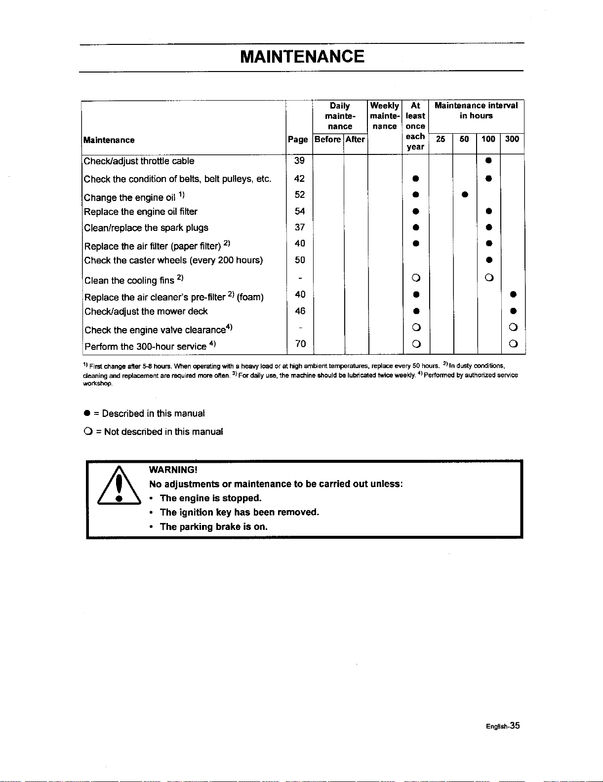
Maintenance Page
Check/adjust throttlecable 39
Check the conditionofbelts, belt pulleys,etc. 42
Change the engine oill) 52
Replace the engine oilfilter 54
Clean/replace the spark plugs 37
Replace the air filter (paperfilter)2) 40
Check the caster wheels (every200 hours) 50
Clean the coolingfins 2)
;Replace theair cleaner's pre-filter2) (foam) 40
Check/adjust the mower deck 46
Check the engine valve clearance4)
Performthe 300-hour service4) 70
Daily
mainte- mainte-
nance nance
Before After
Weekly At Maintenance interval
least in hours
once
each 25 50 t00 300
year
Q Q
o Q
Q Q
!) First change after 5-8 hours. When operating witha heavy load orat high ambient temperatures, replace every 50 hours. 2) In dustyconditions,
c_eaningand rel_acoment are required more often, 3)For daily use,the machine should be lubricated twice weekly, 4)Pedormed by authonzed service
workshop.
• = Described inthis manual
0 = Not described in this manual
]
WARNING!
No adjustments or maintenance to be carried out unless:
• The engine is stopped.
• The ignition key has been removed.
• The parking brake is on.
English-35
MAINTENANCE
Ba_ew
Your mower isequipped with a maintenance free
battery and does not need servicing.However,
periodic charging of the battery with an automotive
type battery charger will extend its life.
Keep battery and terminals clean.
Keep battery boltstight.
Recharge at 6-10 amperes for I hour
To clean battery and terminals
Corrosion and dirt on the battery and
terminals can cause the battery to =leak"
power.
1. Open terminal access deers.
2. Disconnect BLACK battery cable first, then the
RED battery cable and remove the battery from
the machine.
3. Rinse the battery with plain water and dry.
4. Clean terminals and battery cable ends
with wire brush until shiny.
5. Coat terminals with grease or petroleum
jelly
6. Reinstall battery.
I Always use protective glasses
when handling the battery.
IMPORTANT INFORMATION
Do not attempt to open or remove caps
or covers. Adding or checking level of
electrolyte is not necessary.
Always use two wrenches for the
terminal screws
WARNING!
Do not short battery terminals
by allowing a wrench or any
other object to contact both
terminals at the same time.
Before connecting battery,
remove metal bracelets,
wristwatch bands, rings, etc.
Positive terminal must be
connected first to prevent
sparks from accidental
grounding.
I
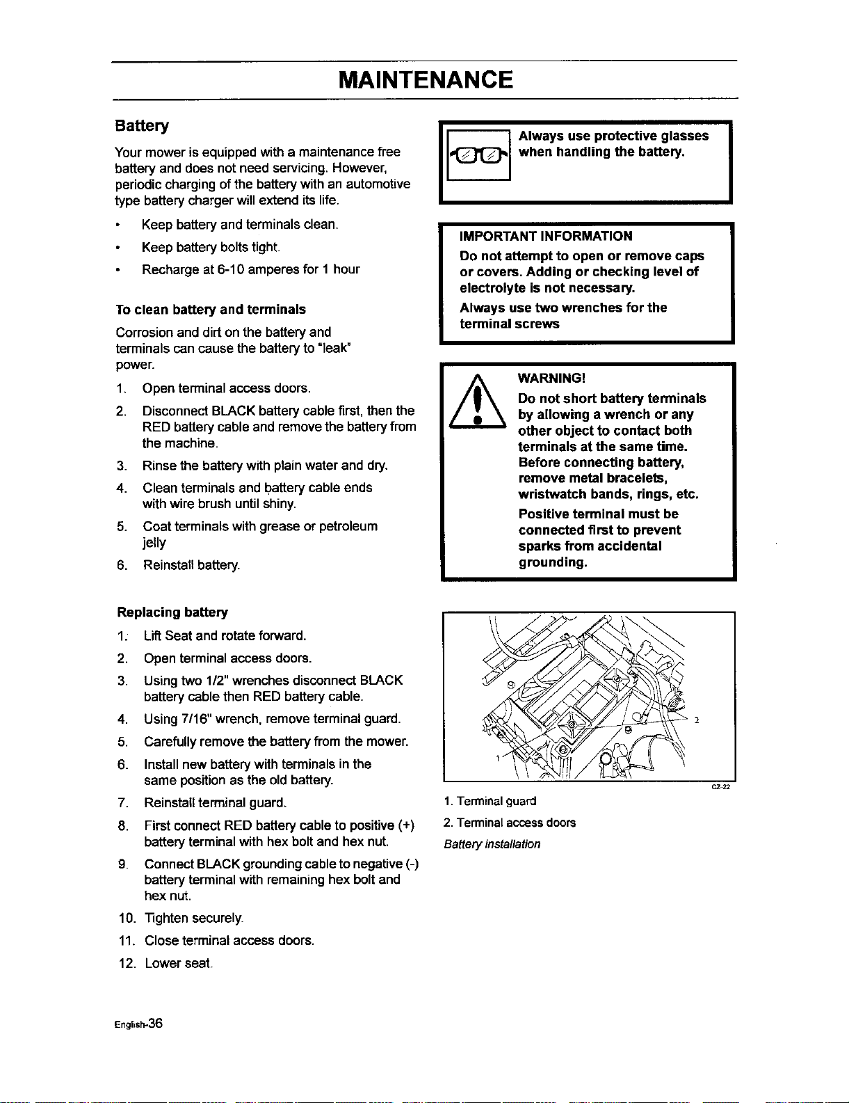
Replacing battery
1: Lif_Seat and rotate forward.
2. Open terminal access doors.
3. Using two 1/2" wrenchesdisconnectBLACK
battery cable then RED battery cable.
4. Using 7/16" wrench, remove terminal guard.
5. Carefully remove the batteryfrom the mower.
6. Installnew batterywith terminals inthe
same positionas the oldbattery.
7. Reinstallterminal guard.
8. FirstconnectRED batterycable to positive(+)
batteryterminal with hexboltand hex nut.
9. ConnectBLACKgroundingcable to negative(-)
batteryterminal with remaininghex boltand
hex nut.
10. "nghtensecurely.
11. Close terminalaccess doors.
12. Lowerseat.
1 .,_
1. Terminal guard
2. Terminal access doors
Battery installation
CZ_2
English-36
MAINTENANCE
Ignition System
The engine is equipped with an electronic
ignition system. Only the sparkplug requires
maintenance.
For recommended spark plug, see Technical
Data.
1. Remove the ignition cable boot and
clean around the spark plug.
2. Remove the spark plug with a spark plug
socketwrench.
3.
Check the spark plug. Replacethe spark
plug if fouled, the electrodes are burned
and if the insulation is cracked or
damaged. Clean the spark plug with a
steel brush if it is to be reused.
4,
5.
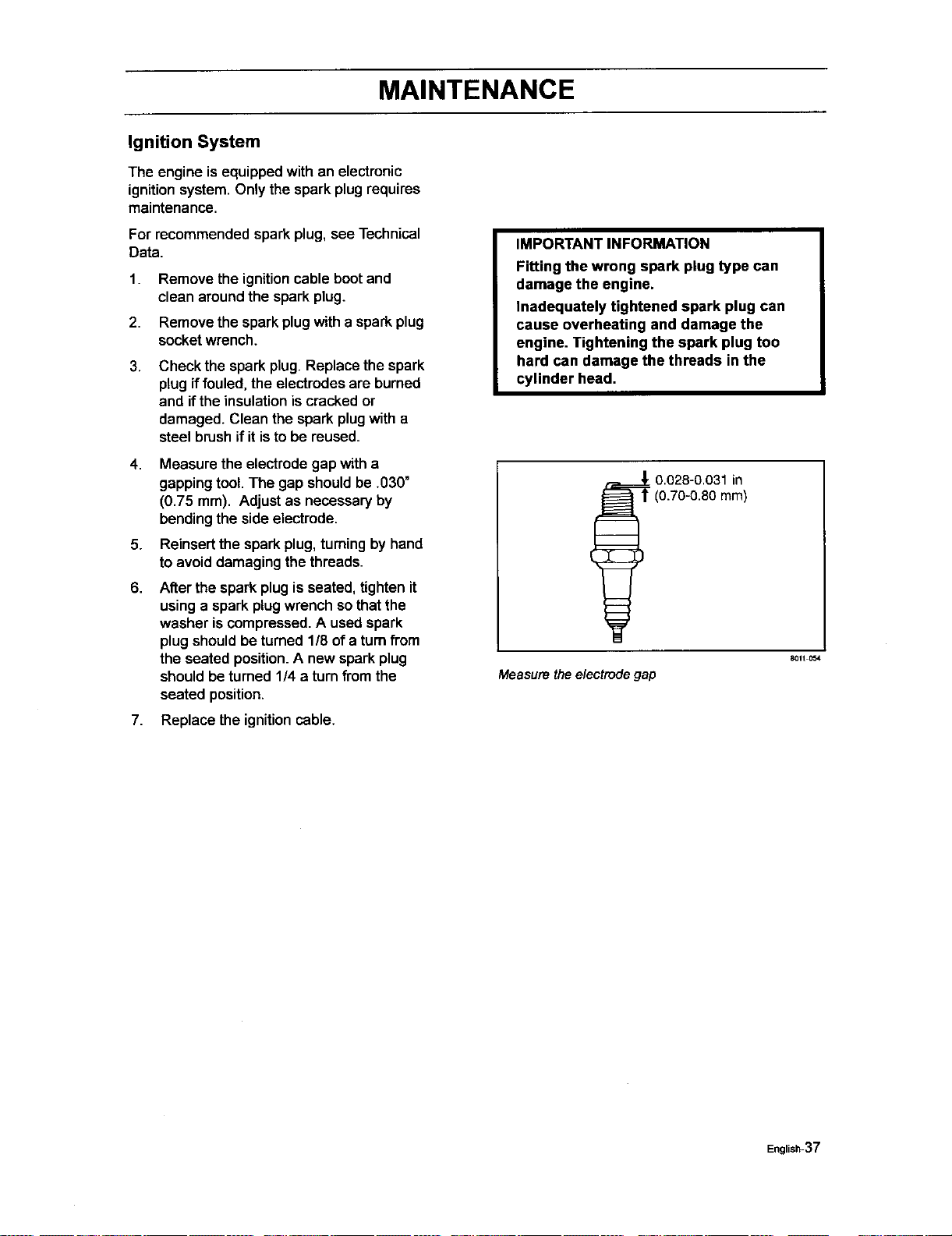
6.
Measure the electrode gap with a
gapping tool. The gap shouldbe .030"
(0.75 mm). Adjust as necessary by
bending the side electrode.
Reinsert the spark plug,turningby hand
to avoid damaging the threads.
After the spark plug is seated, tighten it
using a spark plug wrench sothat the
washer is compressed. A used spark
plug should be turned 1/8 of a turn from
the seated position. A new spark plug
should be turned 1/4 a turn from the
seated position.
7. Replace the ignition cable.
IMPORTANT INFORMATION
Fitting the wrong spark plug type can
damage the engine.
Inadequately tightened spark plug can
cause overheating and damage the
engine. Tightening the spark plug too
hard can damage the threads in the
cylinder head.
0.028-0.031 in
3.70-0.80 mm)
Measure the electrodegap
8011 O54
English-37
MAINTENANCE
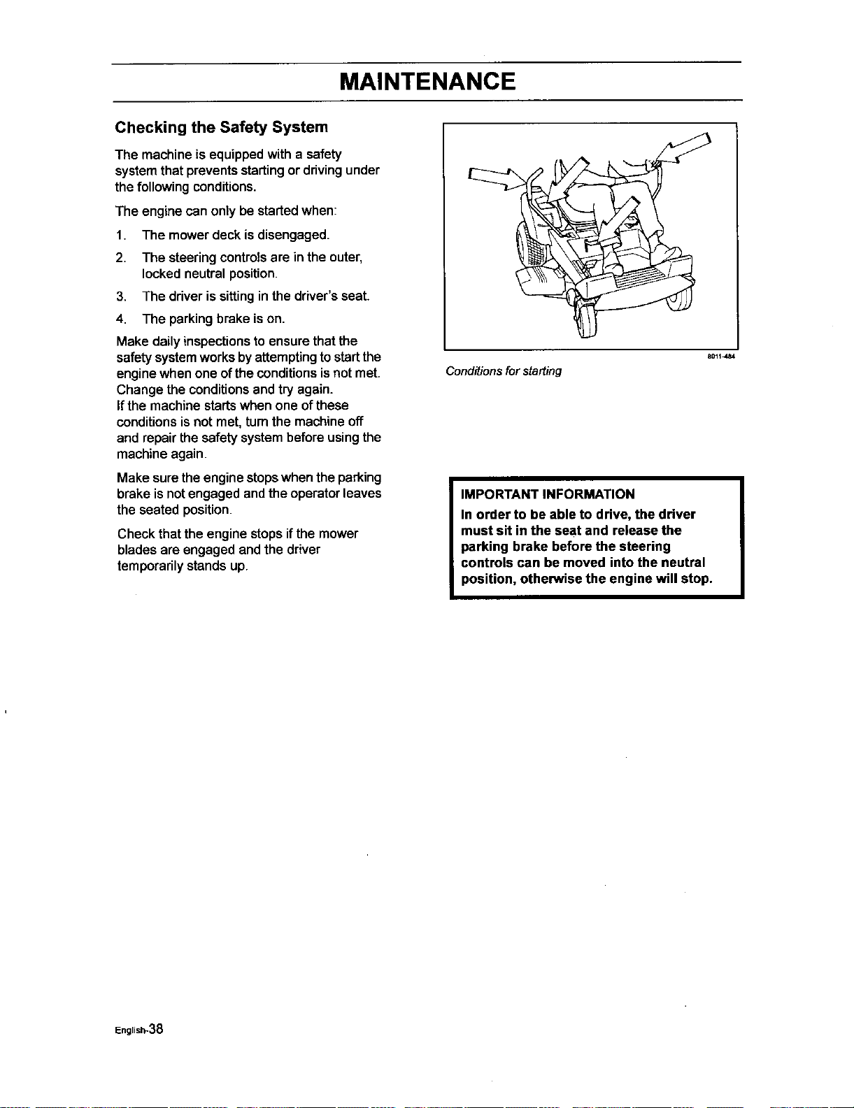
Checking the Safety System
The machine isequipped with a safety
systemthat preventsstartingor drivingunder
thefollowing conditions.
The engine can only be startedwhen:
1. The mower deck is disengaged.
2. The steering controlsare in the outer,
locked neutral position.
3. The driver issittingin the driver's seat.
4. The parkingbrake ison.
Make dailyinspectionsto ensurethat the
safetysystemworks byattemptingto startthe
engine when one ofthe conditionsisnot met.
Change the conditionsand tryagain.
If the machine startswhen one of these
conditions isnot met, tum the machine off
and repairthe safety systembefore usingthe
machine again.
Make surethe engine stopswhen theparking
brake isnotengaged andthe operatorleaves
the seated position.
Check thatthe engine stopsifthe mower
bladesare engaged and the driver
temporarilystands up.
Conditions forstarting
8011J_4
IMPORTANT INFORMATION
In order to be able to drive, the driver
must sit in the seat and release the
parking brake before the steering
controls can be moved into the neutral
position, otherwise the engine will stop.
English-38
MAINTENANCE
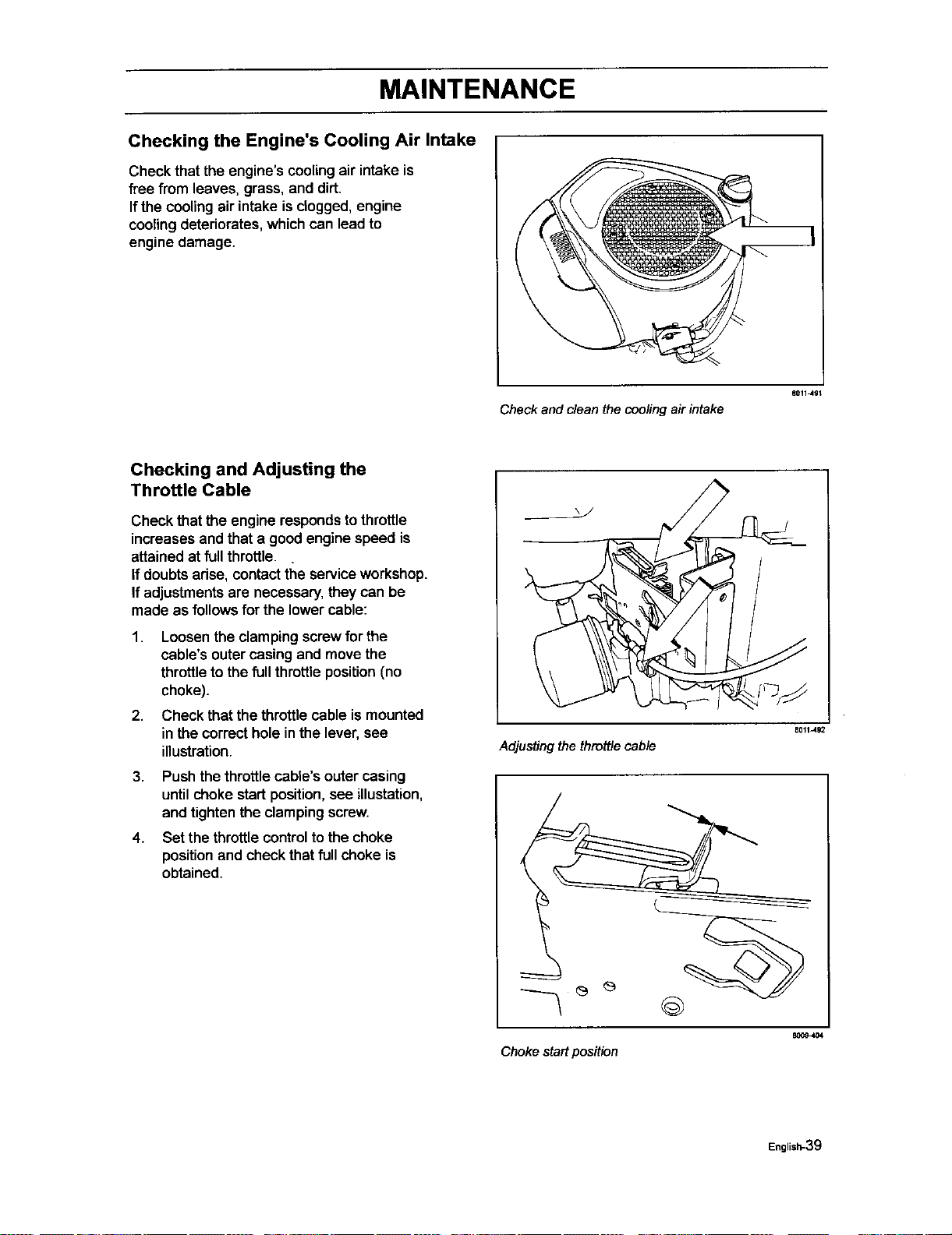
Checking the Engine's Cooling Air Intake
Check that the engine's coolingair intake is
free from leaves, grass, and dirt.
If the cooling air intake is clogged, engine
cooling deteriorates, which can lead to
engine damage.
Check and clean the cooling air intake
801149t
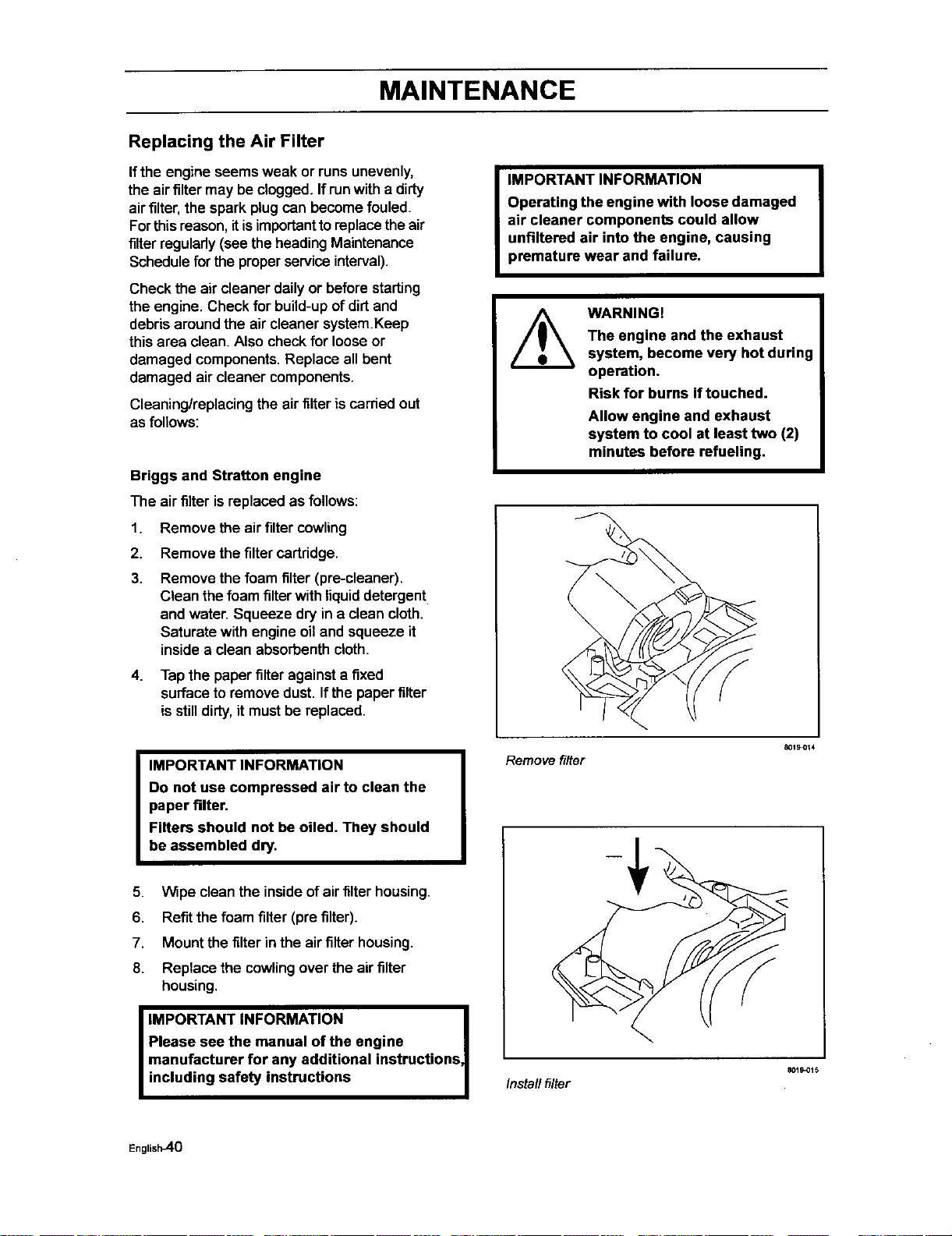
Checking and Adjusting the
Throttle Cable
Check that the engine respondstothrottle
increasesand that a good engine speed is
attained at full throttle.
If doubts adse, contact tl_eservice workshop.
If adjustments are necessary, they can be
made as follows for the lower cable:
1. Loosen the clamping screw for the
cable's outer casing and move the
throttle to the full throttle position (no
choke).
2. Check that the throttle cable is mounted
in the correct hole in the lever, see
illustration.
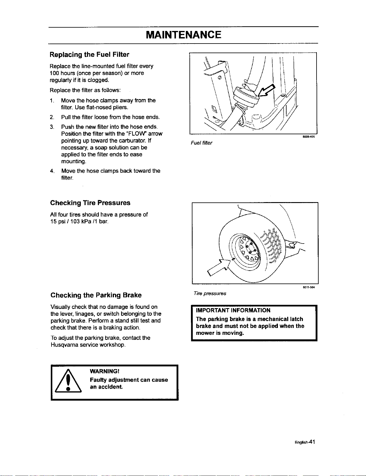
3. Push the throttle cable's outercasing
until choke startposition, see illustation,
and tighten the clamping screw.
4. Set the throttle control to the choke
position and check that full choke is
obtained.
B0114_
Adjustingthethrottlecable
Chokestartposition
8009404
English-39
MAINTENANCE
Replacing the Air Filter
If the engine seems weak or runs unevenly,
the airfiltermay be clogged. If run with a dirty
air filter,the spark plug can become fouled.
Forthismason,itisimportanttoreplacethe air
filterregularly(see theheadingMaintenance
Schedulefor the properservice interval).
Check the air cleaner daily or before starting
the engine. Check for build-up of dirt and
debrisaroundthe air cleaner system.Keep
this area clean. Also check for looseor
damaged components.Replace all bent
damaged aircleaner components.
Cleaning/replacing the air filteris carded out
as follows:
Briggs and Stratton engine
The air filter isreplaced as follows:
1. Remove the air filtercowling
2. Remove the filtercartridge.
3. Remove the foam filter (pre-cleaner).
Clean the foam filterwithliquid detergent
and water. Squeeze dry in a clean cloth.
Saturate with engine oiland squeeze it
insidea clean absorbenthcloth.
4. Tap the paperfilteragainst a fixed
surfaceto remove dust. Ifthe paper filter
is stilldirty,it mustbe replaced.
IMPORTANT INFORMATION
Do not use compressed air to clean the
paper filter.
Filters should not be oiled. They should
be assembled dry.
5. Wipe clean the inside of airfilterhousing.
6. Refit thefoam filter (pre filter).
7. Mount the filterin the air filter housing.
8. Replace the cowling over the air filter
housing.
I IMPORTANT INFORMATION I
Please see the manual of the engine |
manufacturer for any additional instrucUons,I
including safety instructions |
I
IMPORTANT INFORMATION
Operating the engine with loose damaged
air cleaner components could allow
unfiltered air into the engine, causing
premature wear and failure.
WARNING!
The engine and the exhaust
system, become very hot during
operation.
Risk for burns if touched.
Allow engine and exhaust
system to cool at least two (2)
minutes before refueling.
Remove filter
Install filter
801_0t4
8019_15
English_0
MAINTENANCE
Replacing the Fuel Filter
Replace the line-mounted fuel filter every
100 hours (once per season) or more
regularly if it is clogged.
Replace the filter as follows:
1. Move the hose clamps away from the
filter. Use flat-nosed pliers.
2. Pull the filter loose from the hose ends.
3. Push the new filter into the hose ends.
Position the filter with the "FLOW" arrow
pointing up toward the carburator. If
necessary, a soap solution can be
applied to the filter ends to ease
mounting.
4. Move the hose clamps back toward the
filter.
Fuel filter
8009405
Checking Tire Pressures
Allfourtires shouldhave a pressureof
15 psi/ 103 kPa/1 bar.
Checking the Parking Brake
Visually check that no damage isfound on
the lever, linages, or switch belonging to the
parking brake. Perform a stand still test and
check that there is a braking action.
To adjust the parkingbrake, contact the
Husqvarna service workshop.
Tire pressures
8011_64
I MPORTANT INFORMATION I
The parking brake is a mechanical latch
brake and must not be applied when the
mower is moving.
WARNING!
Faulty adjustment can cause
an accident.
I
English_l
MAINTENANCE
Checking the V-belts
WARNING!
No adjustments or maintenance to be carried out unless:
• The engine is stopped.
• The ignition key has been removed.
• The parking brake is on,
Deck belt
V-belts are not adjustable. Replace belts ifthey beginto slipfrom wear.
Deck belt removal
WARNING!
Idler arm is spring loaded. Have
a tight grip on idler arm or
ratchet and release slowly,
Park on a level surface.Apply parking
brake.
Lower the deck into the lowest cutting
position
Disengage belt tension by pushing
inward on deck belt idlerpulley by hand
or with a 1/2" ddve ratchet placed in
square drive hole on idler arm, While arm
is pushed inward, remove belt from
stationary idler pulley and release idler
arm slowly until spdng force is no longer
felt.
Remove bolt from idler pulley. This will
allow belt to pass by the belt guide.
Loosen screws from both leftand dght
plastic belt shield above each mandrel
housing. Remove shields
Remove any dirt or grass that may have
accumulated around the cutter housings
and entire deck surface.
Carefully roll the belt over the top of the
cutter housingpulleys.
Remove the belt from around the electric
clutch on the engine shaft.
The belt can now be removed.
English_42
MAINTENANCE
Deck belt installation
NOTE: For ease in installingthe deck belt,
refer to the routingdecal on bottomof seat.
Wrap the deck belt aroundthe electdc
clutchpulleythat islocated onthe engine
shaft.
Route the belt forward between the EZT
(E-Series Zeroturn Transaxles) and up
onto the deck.
Place belt around spring loaded idler
pulley, between the pulley and guide.
Secure bolt and nut.
Startingon the right hand side of the
deck, wrap the belt aroundthe stationary
idler pulley, the right mandrel housing,
then around to the left mandrel housing.
Push inward on the idler arm and
carefully route belt over stationary idler
pulley. Once belt is properly routed,
slowly release idler arm to tension belt.
Double check belt routing to make sure it
matches the routing decal, and the belt
does not have any twist. Correct as
needed.
Replace belt shields on both mandrel
housings and secure with fasteners.
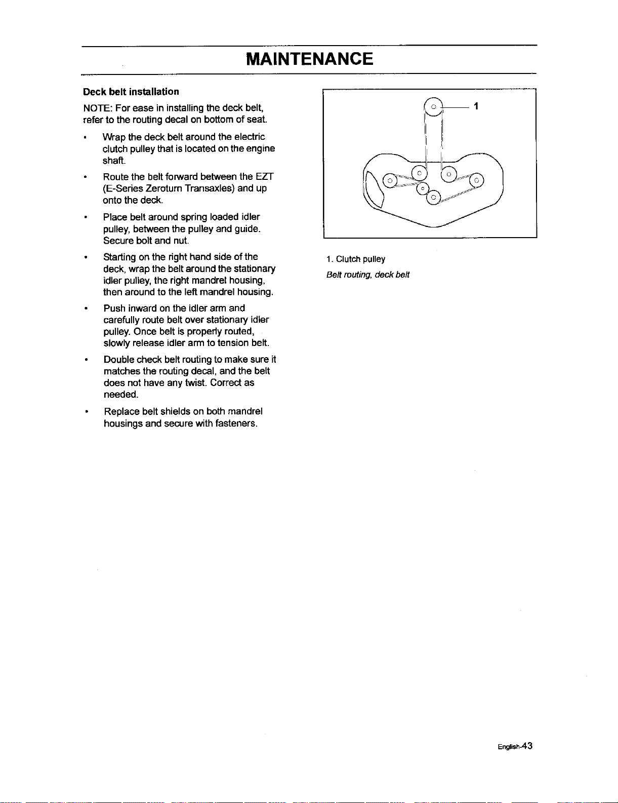
1. Clutch pulley
Belt muting, deck belt
English_3
MAINTENANCE
EZT belt
To replace EZT (E-Series Zeroturn
Transaxle) belt
Park the mower on a level surface. Engage
the parking brake.
EZT belt removal
NOTE: Be careful not to damage the tan
blades on the EZT's as this can affect cooling
or damage the EZT's
Remove the deck belt (see to replace
deck belt in this section of the manual).
Unplug clutch from wiring harness.
Remove bolt from center of clutch and
slide clutch off of engine shaft.
Create slack in the belt by removing the
spdng on the pump idler arm.
The belt should now be able to be
removed from the engine pulley and
EZT pulleys.
Belt installation
Wrap the EZT belt around the EZT
pulleys
Route the belt around the inside of the
idler pulley.
Now you can wrap the belt around the
engine pulley.
Reattach the springon the pump idler
arm.
Installclutchon to engine shaft(pulley
side down) make sure key isinstalled
and alignthe clutchanti rotationtab into
sloton clutch.Secure clutch,installwire.
Reinstall the deck belt ontothe electdc
clutchbelt (see to replace deck belt in
this section of the manual).
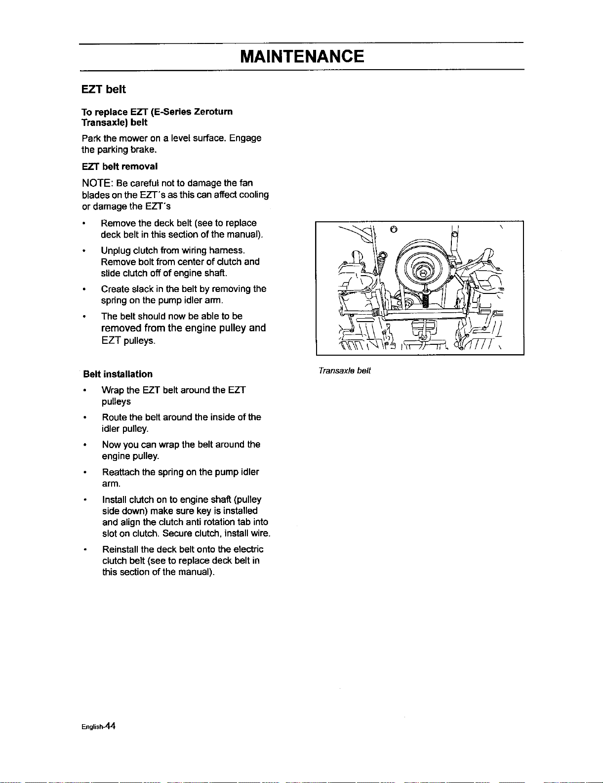
Transaxle belt
English_4
MAINTENANCE
Checking the Blades
In order toattain the best mowing effect, itis
importantthat the blades are well sharpened
and not damaged.
/_ WARNING!
Blades are sharp. Protect your
hands with gloves andlor wrap
blades with a heavy cloth when
_ handling.
Bent or cracked blades or blades with large
nicksshouldbe replaced.
Check the blade mounts.
Check the blades
801t_04
IMPORTANT INFORMATION
The sharpening of blades should be
carried out by an authorized service
workshop.
Damaged blades shouldbe replaced when
hittingobstaclesthat result in a breakdown.
Let the service workshop decide whether the
blade can be repaired/greund or must be
replaced.
I
Blade replacement:
WARNING!
Blades are sharp. Protect your
hands with gloves andlor wrap
blades with a heavy cloth when
handling.
Remove blade bolt by turning
counterclockwise.
I IMPORTANT INFORMATION
To ensure proper assembly, center hole in
blade must align with star on cutter
housing.
4
1
2
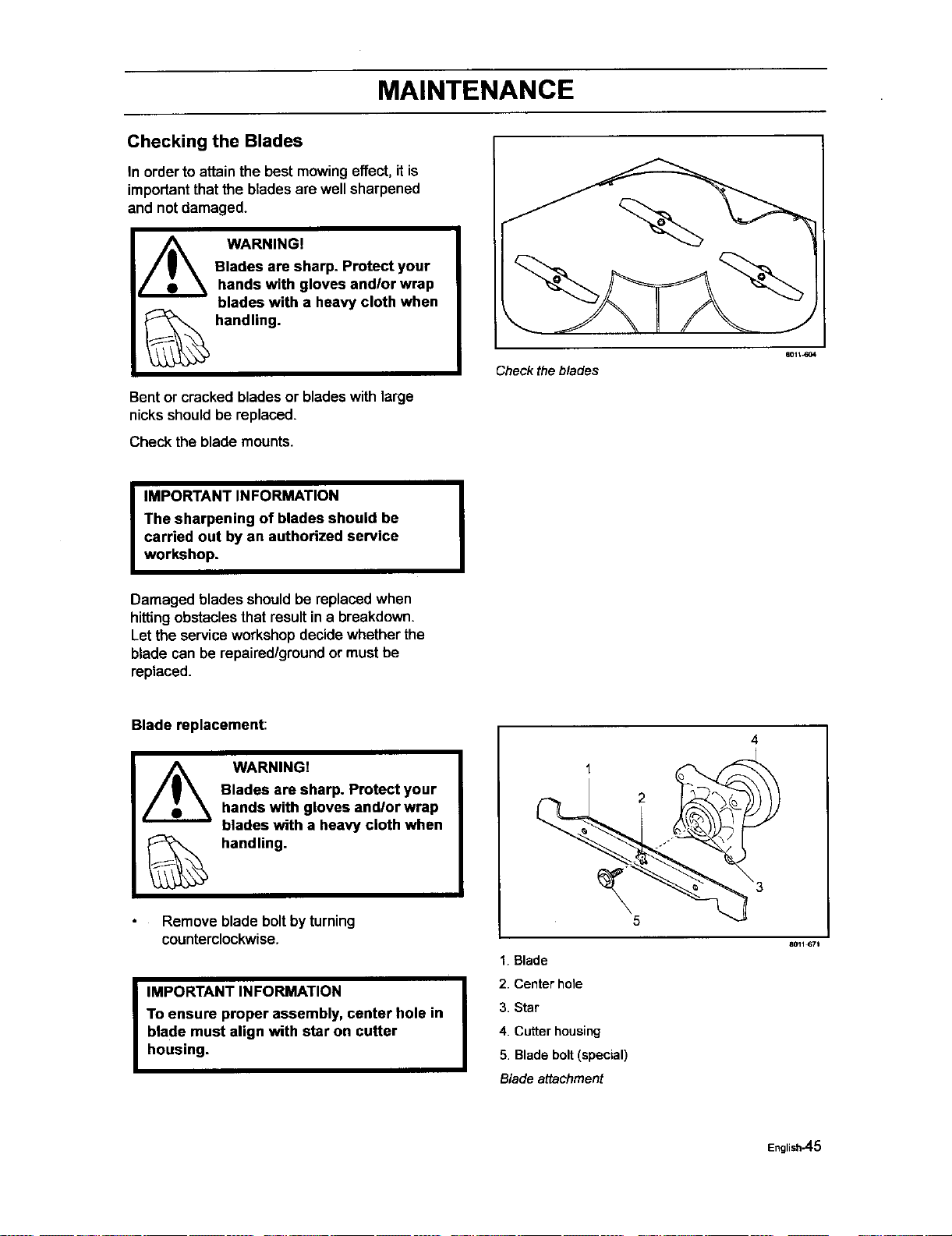
1. Blade
2. Center hole
3. Star
4. Cutter housing
5. Blade bait (special)
Blade attachment
8011_71
English-45
MAINTENANCE
Installnew or re-sharpened blade with
stamped "GRASS SIDE" facing towards
ground/grass (down) or =THIS SIDE UP"
facing deck and cutter housing.
Installand tighten blade boltsecurely.
Torque blade bolt to 27-35 P,JIb
(35-45 Nm).
IMPORTANT INFORMATION
Special blade bolt is heat treated.
Replace with a Husqvarna bolt if required.
Do not use lower grade hardware than
specified.
Adjusting the Mower Deck
WARNING!
Before performing any service or adjustment checklist:
1. Engage the parking brake,
2. Place the Blade-switch in the disengaged position.
3. Turn ignition switch to "OFF" position and remove the key,
4, Make sure the blades and all moving parts have completely stopped.
5, Disconnect the spark plug wire from all spark plugs and place the wire where it
cannot come in contact with the plug.
WARNING!
Blades are sharp. Protect your
hands with gloves and/or wrap
blades with a heavy cloth when
handling.
Chech the tire pressure before adjustment of
the mower deck, see "Checking Tire
Pressure"in Maintenancesection.
Faulty mower deck adjustmentwillcause an
uneven mowing result.
English_6
MAINTENANCE
To level deck
Adjustthe deck whilethe mower is on a level
surface. Make sure the tiresare inflatedto
the correctpressure. See "Technical Data"
underTransmission. Iftires are underor over
inflated,you can not propedyadjustyour
deck.
NOTE: It may be easier to adjustthe front lift
linkagesby removing the floor pan before any
adjustments are made.
Side-to-side adjustment
1. Raise the deck intothe fourinch4"
(102 mm) cuttingposition,
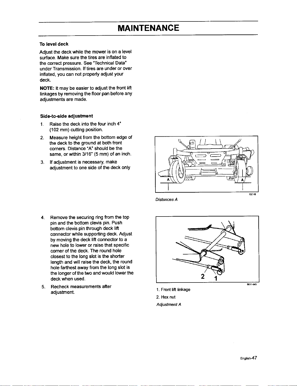
2, Measure heightfrom the bottomedge of
the deckto the groundat bothfront
corners.Distance =A"shouldbethe
same, or within 3/16" (5 mm) ofan inch.
3. If adjustment isnecessary,make
adjustmentto one side ofthe deck only
Distances A
4.
5,
Remove the securingring from the top
pin and the bottom clevis pin. Push
bottom clevis pin through deck lift
connector while supporting deck. Adjust
by moving the deck lift connector to a
new hole to lower or raise that specific
corner of the deck. The round hole
closest to the long slot is the shorter
length and will raise the deck, the round
hole farthest away from the longslotis
thelongerofthetwo and wouldlowerthe
deckwhen used.
Recheck measurements after
adjustment.
2 1
1. Front liftlinkage
2. Hex nut
Adjustment A
8011_a45
Englisi_7
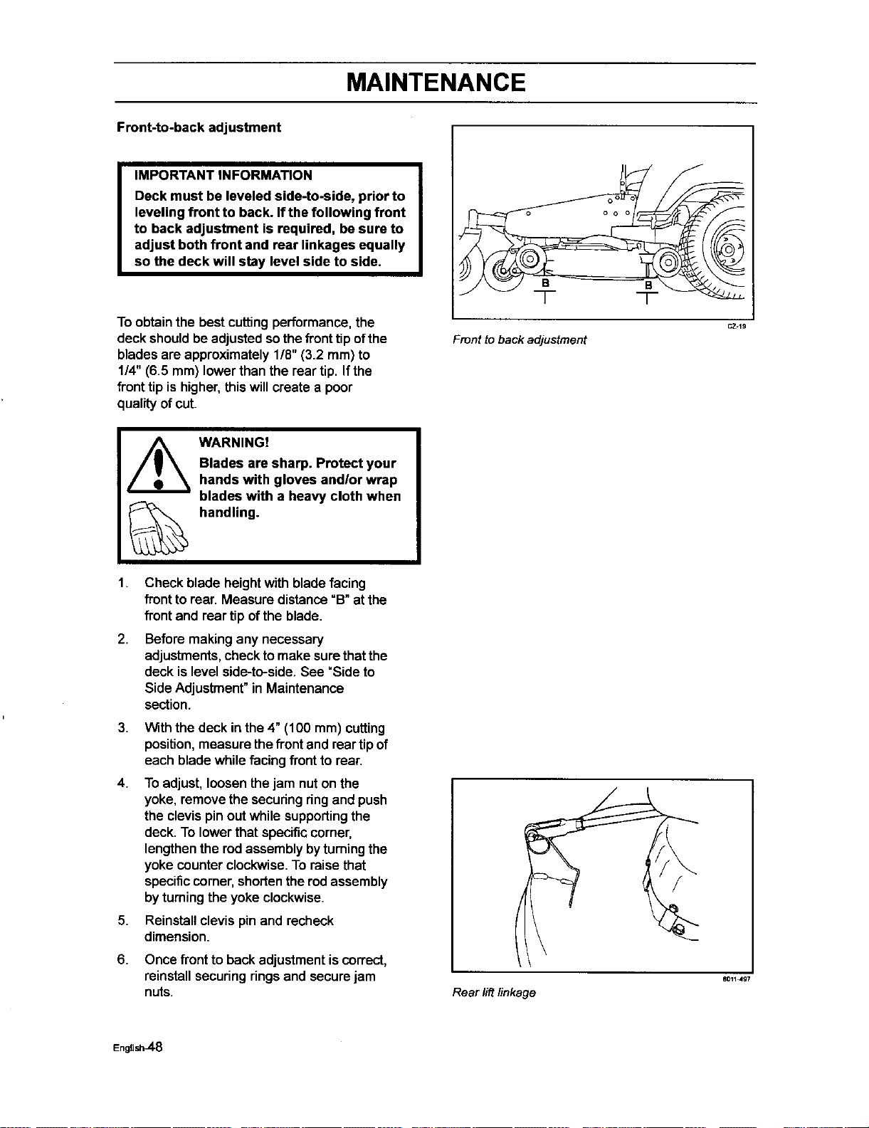
MAINTENANCE
Front-to-back adjustment
IMPORTANT INFORMATION
Deck must be leveled side-to-side, prior to
leveling front to back. If the following front
to back adjustment is required, be sure to
adjust both front and rear linkages equally
so the deck will stay level side to side.
To obtainthe best cutting performance, the
deck shouldbe adjustedsothe fronttip ofthe
blades are approximately 1/8" (3.2 ram) to
1/4" (6.5 mm) lower than the rear tip. If the
front tip is higher, this will create a poor
quality ofcut.
B
T
Front toback adjustment
CZ.19
WARNING!
Blades are sharp. Protect your
hands with gloves and/or wrap
blades with a heavy cloth when
handling.
1. Check blade heightwith blade facing
front to rear. Measure distance =B"at the
front and rear tip of the blade.
2. Before making any necessary
adjustments, check to make sure that the
deck is level side-to-side. See "Side to
Side Adjustment" in Maintenance
section.
3.
4.
5,
6.
With the deck in the4" (100 mm) cutting
position,measure the frontand rear tip of
each bladewhile facingfrontto rear.
To adjust, loosen the jam nuton the
yoke, removethe securingring and push
the clevis pin out while supporting the
deck. To lower that specific corner,
lengthen the rod assembly by turning the
yoke counter clockwise. To raise that
specific corner, shorten the rod assembly
by turning the yoke clockwise.
Reinstallclevis pin and recheck
dimension.
Once front to backadjustment iscorrect,
reinstallsecuringringsand secure jam
nuts.
/
Rear lift linkage
8O11497
English_-8
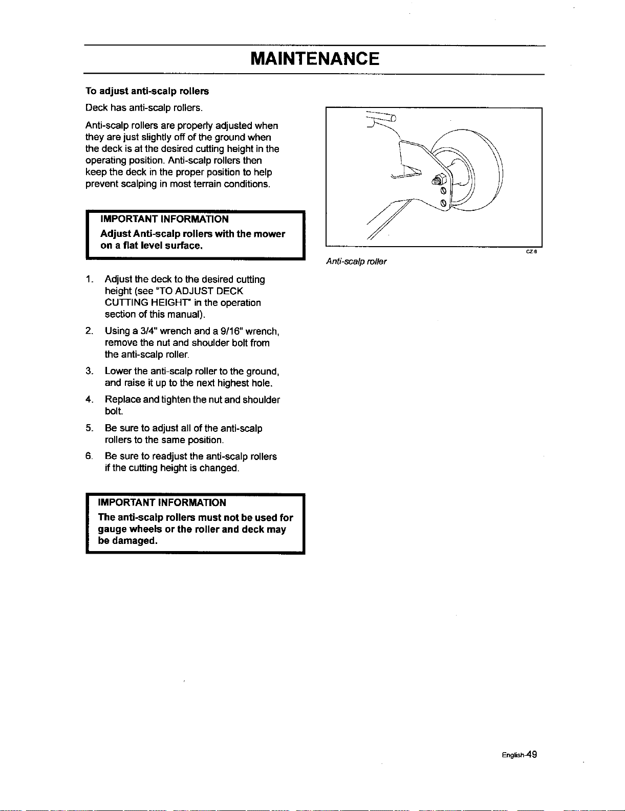
MAINTENANCE
To adjust anti-scalp rollers
Deck has anti-scalpmilers.
Anti-scalp rollers are properlyadjustedwhen
they are just slightlyoff of the groundwhen
the deck isat the desired cuttingheightinthe
operating position.Anti-scalp rollersthen
keep the deck inthe properpositionto help
prevent scalpingin mostterrainconditions.
I
1.
2.
3.
4.
5.
6.
IMPORTANT INFORMATION I
Adjust Anti-scalp rollers with the mower
on a flat level surface,
Adjustthe deck to the desired cutting
height (see "TO ADJUST DECK
CUTTING HEIGHT" in the operation
sectionofthis manual).
Using a 314"wrenchand a 9/16" wrench,
remove the nut and shoulderbolt from
the anti-scalp roller.
Lower the anti-scalprollertothe ground,
and raise it up to the next highest hole.
Replace and tighten the nut and shoulder
bolt.
Be sureto adjustall ofthe anti-scalp
milers tothe same position.
Be sureto readjustthe anti-scalprollers
ifthe cuttingheight is changed.
Anti-sca/p ro/ler
CZg
I IMPORTANT INFORMATION I
The anti-scalp rollers must not be used for
gauge wheels or the roller and deck may
be damaged,
English_9
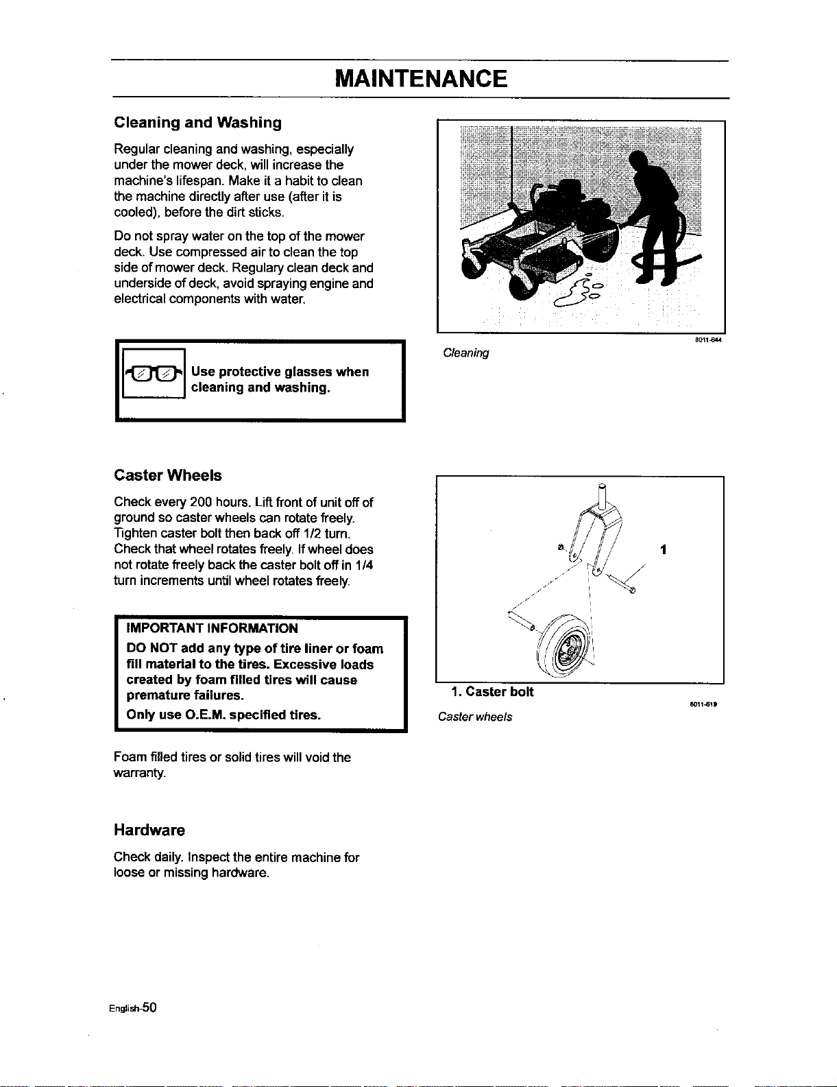
MAINTENANCE
Cleaning and Washing
Regular cleaningand washing, especially
under the mower deck, will increase the
machine's lifespan. Make it a habit to clean
the machine directly after use (after it is
cooled), before the dirt sticks.
Do not spraywater on the top of the mower
deck. Use compressed air to cleanthe top
side of mower deck. Regulary clean deck and
underside of deck, avoid spraying engine and
electrical components with water.
Use protective glasses when
cleaning and washing.
I
Cleaning
_011J_44
Caster Wheels
Check every 200 hours.Liftfront of unit off of
groundso caster wheels can rotate freely.
"nghten caster bolt then back off 1/2 turn.
Check that wheel rotates freely. If wheel does
not rotate freely back the caster bolt off in 1/4
turn increments until wheel rotates freely.
IMPORTANT INFORMATION
DO NOT add any type of tire liner or foam
fill material to the tires. Excessive loads
created by foam filled tires will cause
premature failures.
Only use O.E.M. specified tires.
1
/
/ / i
i
1. Caster bolt
80H-619
Caster wheels
Foam filled tires or solidtires will void the
warranty.
Hardware
Check daily. Inspect the entiremachinefor
looseor missinghardware,
English-5O
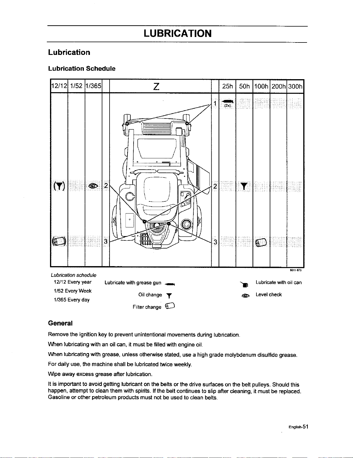
LUBRICATION
Lubrication
Lubrication Schedule
12/12 1/52 1/365 Z
25h 50h lOOh 200h 300h
I I I
\
8011_73
Lubricationschedule
12J12Everyyear Lubricatewithgreasegun _ "_ Lubricatewith oil can
1/52EveryWeek
Oil change • d_, Levelcheck
1/365Everyday
Filterchange
General
Remove the ignitionkey to preventunintentional movements during lubrication.
When lubricating with an oil can, it must be filledwith engine oil.
When lubdcating with grease, unless otherwise stated, use a high grade molybdenum disulfide grease.
For daily use, the machine shall be lubricated twice weekly.
Wipe away excess grease after lubrication.
It isimportantto avoidgetting lubricanton the belts or the drivesurfaces on the belt pulleys.Shouldthis
happen, attemptto clean themwith spirits.Ifthe beltcontinuesto slipafter cleaning,it must be replaced.
Gasoline or other petroleum productsmustnot be used to clean belts.
English-51
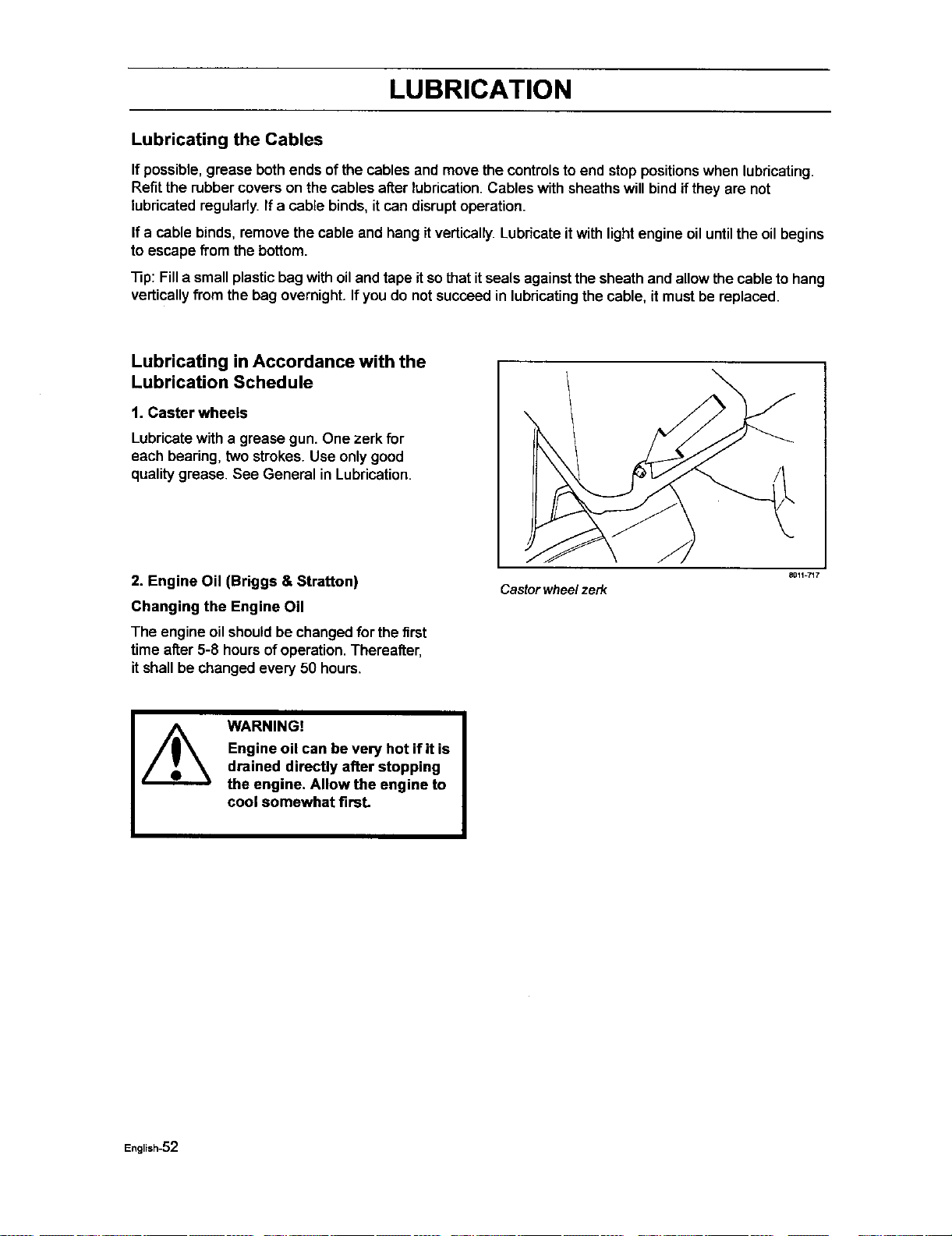
LUBRICATION
Lubricating the Cables
If possible, grease both ends of the cables and movethe controls toend stop positions when lubricating.
Refit the rubbercovers on the cables after lubrication.Cables with sheathswill bindifthey are not
lubricatedregularty.If a ceble binds, itcan disruptoperation.
If a cable binds, remove the cable and hang it vertically.Lubricateitwith light engine oiluntilthe oilbegins
to escape fromthe bottom.
_p: Filla small plastic bag with oiland tape itso that itseals againstthe sheath and allowthe cable to hang
verticallyfrom the bag overnight.Ifyou do notsucceed in lubricatingthe cable, it mustbe replaced.
Lubricating in Accordance with the
Lubrication Schedule
1. Caster wheels
Lubricatewitha grease gun. One zerk for
each bearing,two strokes.Use onlygood
qualitygrease. See General in Lubrication.
2. Engine Oil (Briggs & Stratton)
Changing the Engine Oil
The engine oilshouldbe changedfor the first
time after5-8 hoursof operation,Thereafter,
itshall be changed every 50 hours,
Castor wheel zerk
8011-717
WARNING!
Engine oil can be very hot if it is
drained directly after stopping
the engine, Allow the engine to
cool somewhat firaL
English-52
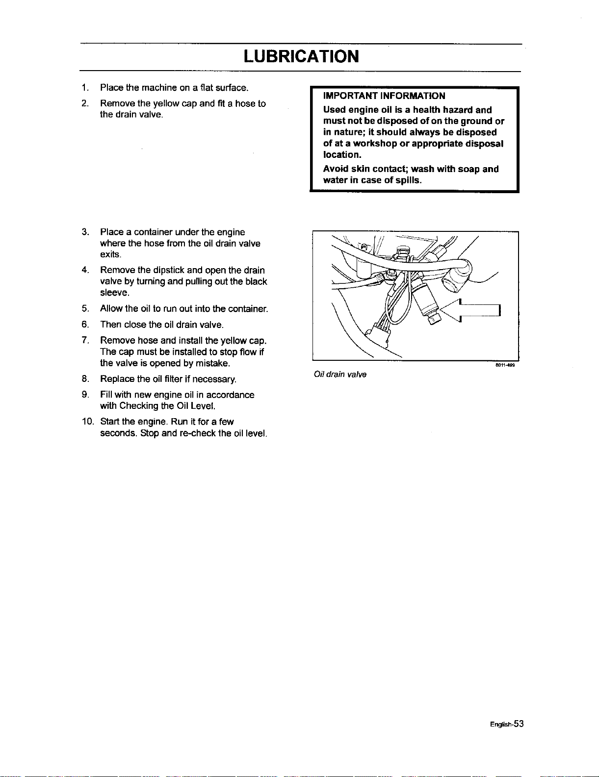
LUBRICATION
1. Place the machine on a flat surface.
2. Remove the yellow cap and fit a hose to
the drain valve.
IMPORTANT INFORMATION
Used engine oil is a health hazard and
must not be disposed of on the ground or
in nature; it should always be disposed
of at a workshop or appropriate disposal
location.
Avoid skin contact; wash with soap and
water in case of spills.
3. Place a container under the engine
where the hosefrom the oildrain valve
exits.
4. Remove the dipstick and openthe drain
valve by turning and pulling out the black
sleeve.
5. Allow the oilto run out intothe container.
6. Then close the oil drain valve.
7,
8.
9.
Remove hose and install the yellow cap.
The cap mustbe installedto stopflow if
the valve isopened bymistake.
Replace the oilfilter ifnecessary.
Fill with new engine oil in accordance
with Checking the Oil Level.
10. Startthe engine. Run itfor a few
seconds. Stop and re-check the oillevel.
Oil drain valve
B011499
English-53
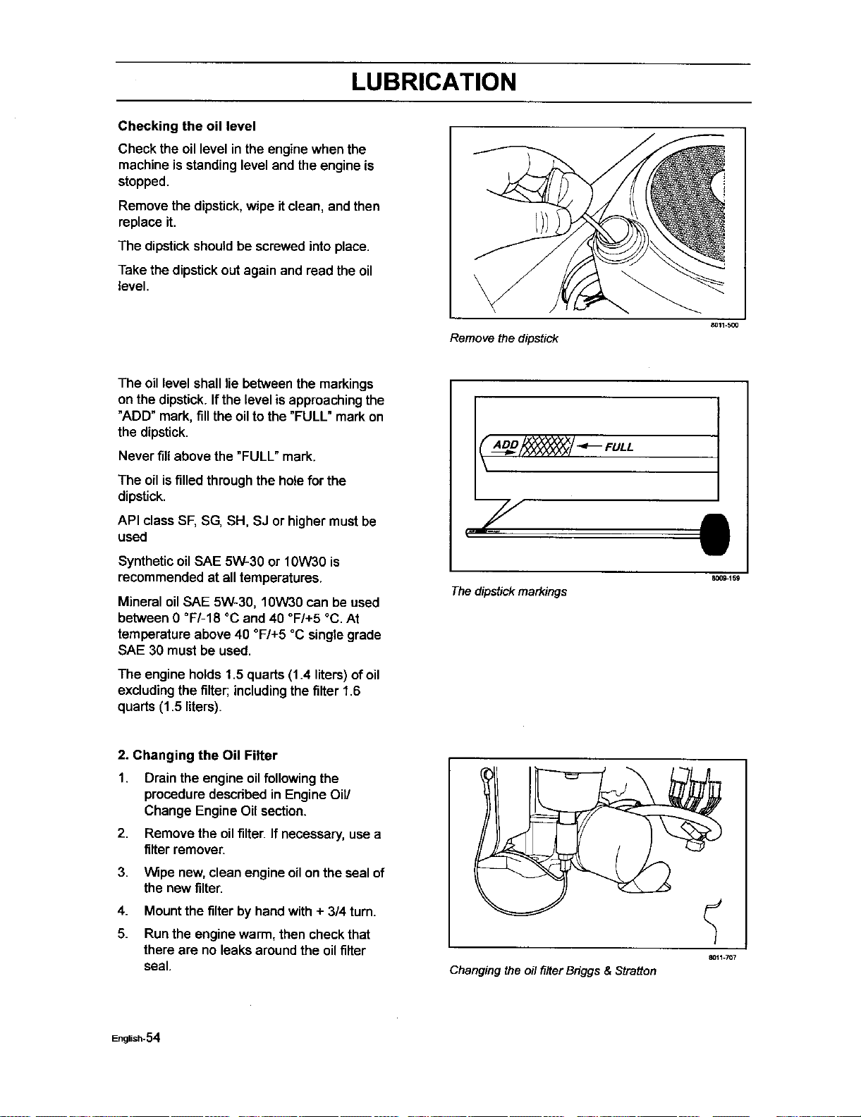
LUBRICATION
Checking the oil level
Check the oil level in the engine when the
machine is standing level and the engine is
stopped.
Remove the dipstick, wipe it clean, and then
replace it.
The dipstick should be screwed into place.
Take the dipstick out again and read the oil
level.
8011-900
Remove the dipstick
The oil level shalllie between the markings
on the dipstick. If the level isapproachingthe
"ADD" mark, fill the oil to the "FULL" mark on
the dipstick.
Never fill above the "FULL" mark.
The oil is filled through the hole for the
dipstick.
API class SF, SG, SH, SJ or higher must be
used
Syntheticoil SAE 5W-30 or 10W30 is
recommended at alltemperatures.
Mineral oil SAE 5W-30, 10W30 can be used
between 0 °F/-18 °C and 40 °F/+5 °C. At
temperature above 40 °F/+5 °C single grade
SAE 30 must be used.
The engine holds 1.5 quarts (1.4 liters) ofoil
excluding the filter; includingthe filter 1.6
quarts (1.5 liters).
_/ _ FULL
7
The dipstick markings
II
800_159
2. Changing the Oil Filter
1. Drain the engineoil followingthe
procedure described in Engine Oil/
Change Engine Oil section.
2. Remove the oil filter. If necessary, use a
filter remover.
3. Wipe new, clean engine oil on the seal of
the new filter.
4. Mount the filter by hand with + 3/4 turn.
5. Run the engine warm, then check that
there are no leaks around the oil filter
seal.
Changing the oil filter Bdggs & Stratton
English-S4
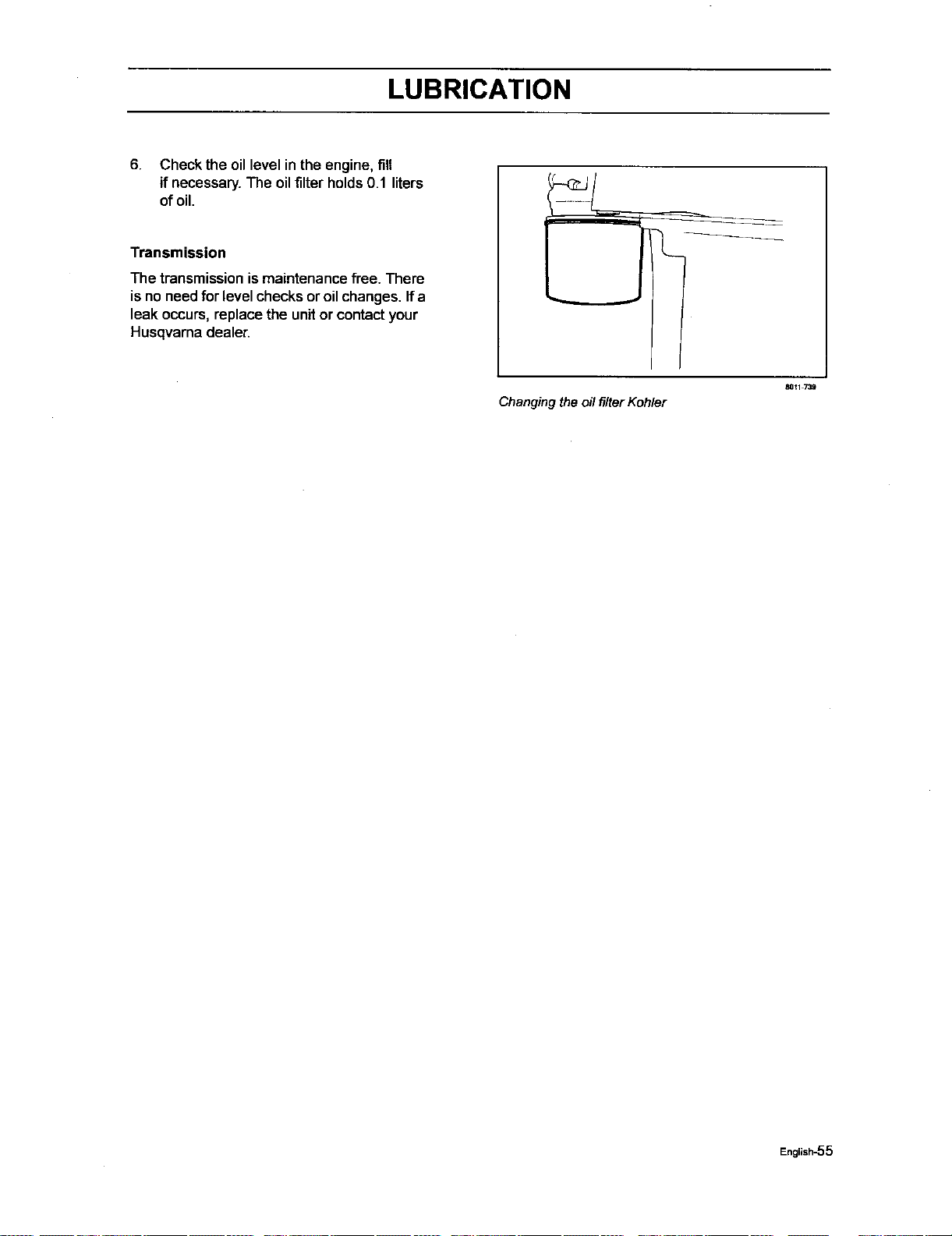
LUBRICATION
6. Check the oillevel in the engine, fill
if necessary.The oilfilter holds0.1 liters
of oil.
Transmission
The transmission is maintenance free. There
is no needfor level checksor oilchanges. If a
leak occurs, replace the unit or contact your
Husqvarna dealer.
Changing the oil filter Kohler
80_1 739
English-55

TROUBLE SHOOTING GUIDE
Trouble Shooting Guide
Problem Cause
The engine willnot start.
The blade switchis engaged.
The steeringcontrolsare not lockedinthe
neutral position.
The driveris not sittingin the driver'sseat.
The parkingbrake is not activated.
The battery isdead.
Contaminationinthe carburetoror fuel line.
The fuel supplyisclosed orthe tap
for the fuel tanks isin the wrong position.
Clogged fuel filteror fuel line.
The starter motordoes not turn the engine over.
Dead battery.
Poorcontacts onthe batteryterminal
cable connections.
Fuse blown.
Ignitionsystem faulty.
Fault in the startermotorsafety circuit.
See Checkingthe Safety System inthe
Maintenance section.
The engine runs rough.
Faultycarburetor.
The chokecontrol ispulled outwitha warmengine.
Defective valves.
Defective piston,cylinder, pistonring,or
cylinderhead seal.
The cylinderhead boltsare loose.
Clogged fuel filterorjet.
Clogged ventilationvalve on thefuel cap.
Fueltank nearly empty.
Defective spark plug.
The spark plug is loose.
Defective ignitioncable.
Defective spark plugelectrode.
Defective spark plugconnection.
Rich fuel mixture or fuel-air mixture.
English-56

TROUBLE SHOOTING GUIDE
Wrong fuel type.
Water in thefuel.
Clogged air filter.
The engine seems weak. Clogged air filter.
Defective spark plug.
Carburetor incorrectlyadjusted.
The engine overheats.
Clogged air intake or coolingfins.
Engine overloaded.
Poorventilationaround engine.
Defective engine speed regulator.
Soot inthe combustionchamber.
Too littleor no oil inthe engine.
Defective spark plug.
Pre-ignitionincorrect.
Battery notcharging.
Poorcontact with battery terminal
cable connectors.
The machinemoves slowly, unevenly,
or not at all.
Parking brake on.
Bypass valve on pump open.
Ddve belt for thetransmissiongears slackor
hascome off.
Mower deck not engaging.
Drivebelt for the mower deck hascome loose.
Contactfor the electromagneticcoupling
hasloosened.
The blade switchis faultyor has come loose
,fromthecable contact.
The fuse has blown.
English-57

TROUBLE SHOOTING GUIDE
Uneven mowingresults. Differentair pressure inthe tires on the left and
right sides.
Bent blades.
The suspending for the mower deck
is uneven.
The blades are blunt.
Driving speed too high.
The grass is too long.
Grass collected under the mower deck.
The machine vibrates. The blades are loose.
The blades are incorrectly balanced.
The engine isloose.
English-58
STORAGE
Storage
Winter Storage
At the end of the mowing season, the machine
shouldbe readied for storage (or ifit will not be in
use for longerthan 30 days). Fuelallowed to
stand for long periodsoftime (30 days or more)
can leave stickyresiduesthat can foulthe
carburetor and disruptengine function.
Fuel stabilizersare an acceptableoptionas
regards tothe stickyresiduesthat can occur
duringstorage.
Add stabilizer to the fuel inthe tank or in the
storage container.Always use the mixingratios
specifiedby the manufacturerofthe stabilizer.
Run the engine for at least 10 minutesatter
addingthe stabilizer sothat itreaches the
carburetor. Do not emptythe fuel tank and the
carburetor ifyou have added stabilizer.
WARNING!
Never store an engine with fuel
in the tank indoors or in poorly
ventilated spaces where fuel
vapor can come in contact with
open flames, sparks, or a pilot
light such as in a boiler, hot
water tank, clothes drier, etc.
Handle the fuel with care. It is
very flammable and careless
use can cause serious personal
injury and property damage.
Drain the fuel into an approved
container outdoors and far
away from open flame. Never
use gasoline for cleaning. Use
a degreaser and warm water
instead.
To ready the machinefor storage,follow these
steps:
1.
Thoroughlyclean the machine, especially
under the mower deck. Touch up damage to
the paintand spray a thin layer ofoil onthe
undersideofthe mower deck toavoid
corrosion.
2. Inspectthe machinefor wornor damaged
parts and tighten any nutsorscrewsthat may
have become loose.
3.
4.
Change the engine oil;disposeof properly.
Empty thefuel tanks or add a fuel stabilizer.
Startthe engineand allowit torun untilthe
carburetor is drainedoffuel or thestabilizer
has reachedthe carburetor.
5.
6.
7.
Remove the spark plug and pour abouta
tablespoonof engine oilintothe cylinder.
Turn over the engine so thatthe oilis evenly
distributedand then refitthe spark plug.
Lubricateall grease zerks,joints,and axles.
Remove the battery.Clean, charge, and store
the batteryin a cool place, but protectitfrom
directcold.
8. Store the machine in a clean, dry place and
cover itfor extraprotection.
Service
When orderingspare parts, please specifythe
purchase year, model, type, and sedal number.
Always use genuine Husqvama spare parts.
An annual check-up at an authorized service
workshop is a good way to ensure that your
machine performs its best the following season.
English_59
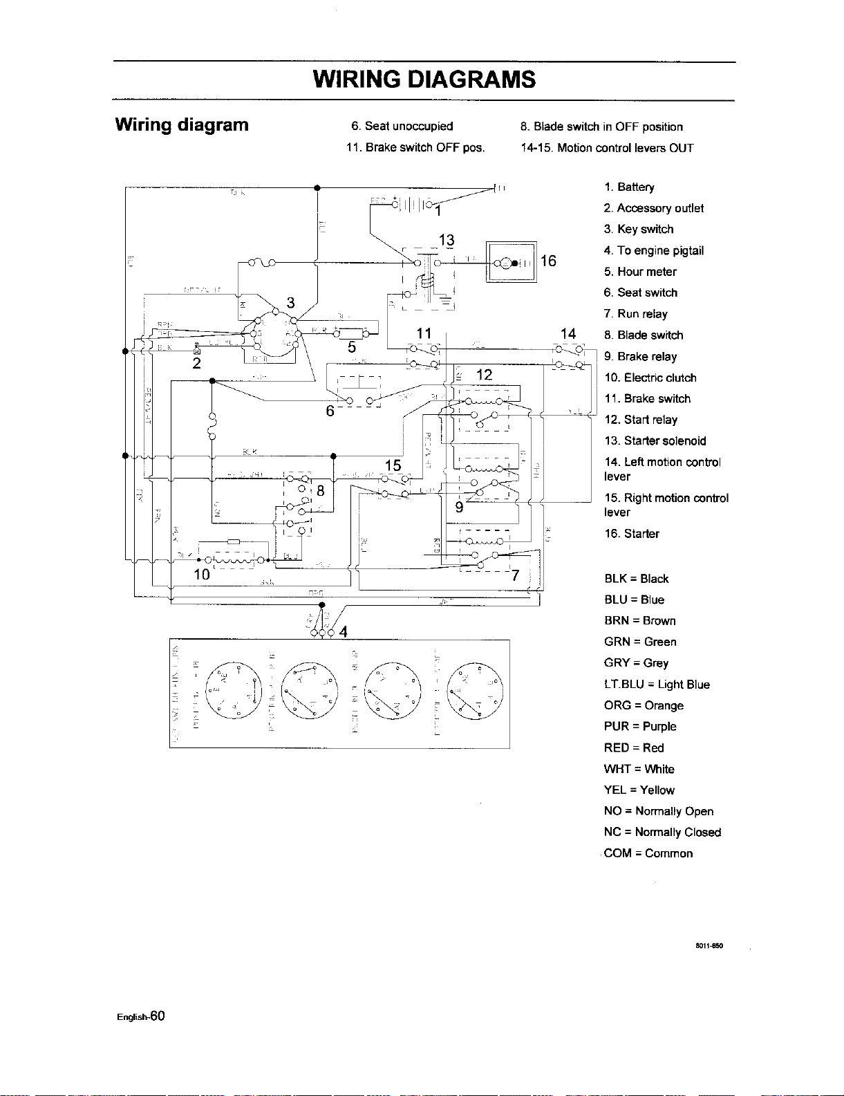
WIRING DIAGRAMS
Wiring diagram
6. Seat unoccupied
11. Brake switchOFF pos.
8. Blade switchin OFF position
14-15. Motioncontrol levers OUT
1. Battery
2. Accessory outlet
3. Key switch
4. To engine pigtail
5. Hour meter
6. Seat switch
2
14
7. Run relay
8. Blade switch
9. Brake relay
10. Electric clutch
11. Brake switch
12. Start relay
13. Starter solenoid
14. Left motion control
lever
15. Right motion control
lever
16. Starter
BLK = Black
BLU = Blue
BRN = Brown
GRN = Green
GRY = Grey
LT.BLU = Light Blue
ORG = Orange
PUR = Purple
RED = Red
WHT = White
YEL = Yellow
NO = NormallyOpen
NC = Normally Closed
COM = Common
8011_50
English-60
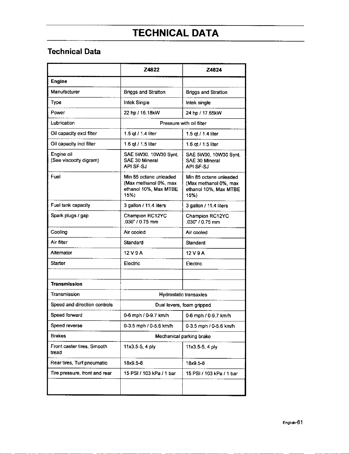
TECHNICAL DATA
Technical Data
Z4822 Z4824
Engine
Manufacturer Briggsand Straiten Briggsand Stratton
Type thtek Single Intek single
Power 22 hp / 16.18kW 24 hp/ 17.65kW
Lubrication Pressure with oilfilter
Oil capacity excl filter 1.5 qt / 1.4 liter 1.5 qt / 1.4 liter
Oil capacity inclfilter 1.6 qt/ 1.5 liter 1.6 qt / 1.5 liter
Engine oil SAE 5W30, 10W30 Synt. SAE 5W30, 10W30 Synt.
(See viscocitydigram) SAE 30 Mineral SAE 30 Mineral
API SF-SJ API SF-SJ
Fuel Min85 octane unleaded Min 85 octane unleaded
(Max methanol 0%, max (Max methanol 0%, max
ethanol 10%, Max MTBE ethanol 10%, Max MTBE
15%) 15%)
Fuel tankcapacity 3 gallon / 11.4 liters 3 gallon/ 11.4liters
Spark plugs/ gap Champion RC12YC Champion RC12YC
.030" / 0.75 mm .030" / 0.75 mm
Cooling Air cooled Air cooled
Air filter Standard Standard
Alternator 12 V 9 A 12 V 9 A
Starter Electric Electnc
Transmission
Transmission Hydrostatictransaxles
Speed and directioncontrols Dual levers, foam gripped
Speed forward 0-6 mph / 0-g.7 km/h 0-6 mph / 0-9.7 km/h
Speed reverse 0-3.5 mph / 0-5.6 km/h 0-3.5 mph / 0-5.6 km/h
Brakes Mechanical parkingbrake
Front castertires, Smooth 11x3.5-5, 4 ply 11x3.5-5, 4 ply
tread
Rear tires, Turfpneumatic 18x9.5-6 18x9.5-6
Tire pressure, fi'ont and rear 15 PSi / 103 kPa / 1 bar 15 PSI / 103 kPa / 1 bar
English-61
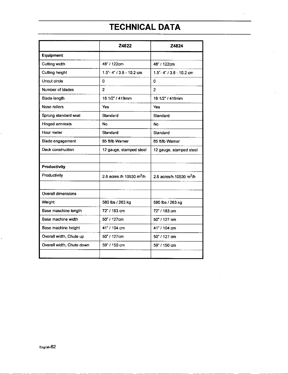
TECHNICAL DATA
Equipment
Cutting width
Cutting height
Uncutcircle
Number of blades
Blade length
Nose rollers
Sprung standard seat
Hinged armrests
Hour meter
Blade engagement
Deck construction
Productivity
Productivity
Overall dimensions
Weight
Base maschine length
Base machine width
Base machine height
Overall width, Chute up
Overall width, Chute down
Z4822
48" / 122cm
1.5"-4 _/3.8 - 10.2 cm
0
2
16 1/2"/ 419mm
Yes
Standard
No
Standard
85 ft/IbWarner
12 gauge, stamped steel
2.6 acres/h 10530 m2/h
580 Ibs / 263 kg
72" / 183 cm
50" / 127cm
41"/104 cm
50" / 127cm
59" / 150 cm
Z4824
48" / 122cm
1.5"-4" / 3.8 - 10.2 cm
0
2
16 1/2" / 419mm
Yes
Standard
No
Standard
85 ff/Ib Warner
12 gauge, stamped steel
2.6 acres/h 10530 m2/h
580 Ibs / 263 kg
72"/ 183 crn
50"/ 127 cm
41"/104 cm
50" / 127 crn
59"/150 cm
English-62
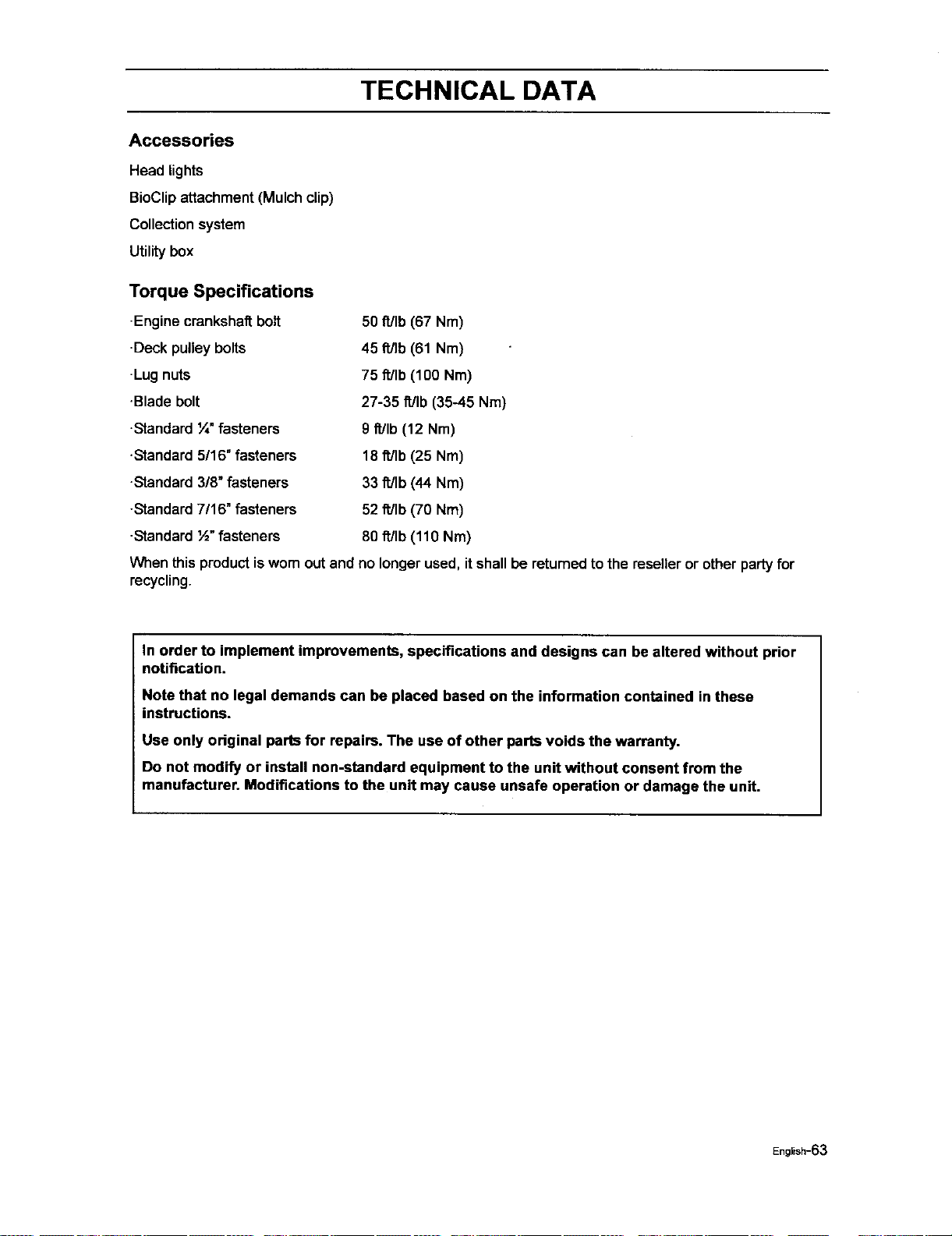
TECHNICAL DATA
Accessories
Head lights
BioClipattachment (Mulch clip)
Collection system
Utility box
Torque Specifications
-Engine crankshaftbolt
•Deck pulleybolts
-Lugnuts
•Blade bolt
•Standardt/4"fasteners
•Standard 5/16" fasteners
•Standard 3/8" fasteners
-Standard7/16" fasteners
-Standard½" fasteners
50 ft/Ib (67 Nm)
45 fl/Ib (61 Nm)
75 ft/Ib (100 Nm)
27-35 ft/Ib (35-45 Nm)
9 fdlb (12 Nm)
18 ft/Ib (25 Nm)
33 fdlb (44 Nm)
52 fdlb (70 Nm)
80 fdlb (110 Nm)
When this productis wornout and no longerused, itshallbe returnedto the reseller or other party for
recycling.
In order to implement improvements, specifications and designs can be altered without prior
notification.
Note that no legal demands can be placed based on the information contained in these
instructions.
Use only original parts for repairs. The use of other parts voids the warranty.
Do not modify or install non-standard equipment to the unit without consent from the
manufacturer. Modifications to the unit may cause unsafe operation or damage the unit.
English-63

CONFORMITY CERTIFICATES
Conformity Certificates
USA requirements
Labels are placed on the engine and/or in the engine compartment statingthatthe machinewillfulfill the
requirements. This isalso applicable to special requirements for any of the states, (Californian emission
rules etc.). Do not remove any of these labels. Certificates can also be supplied with the machine at
delivery or written in the Engine manual. Take care of them as valuable documents.
English-64
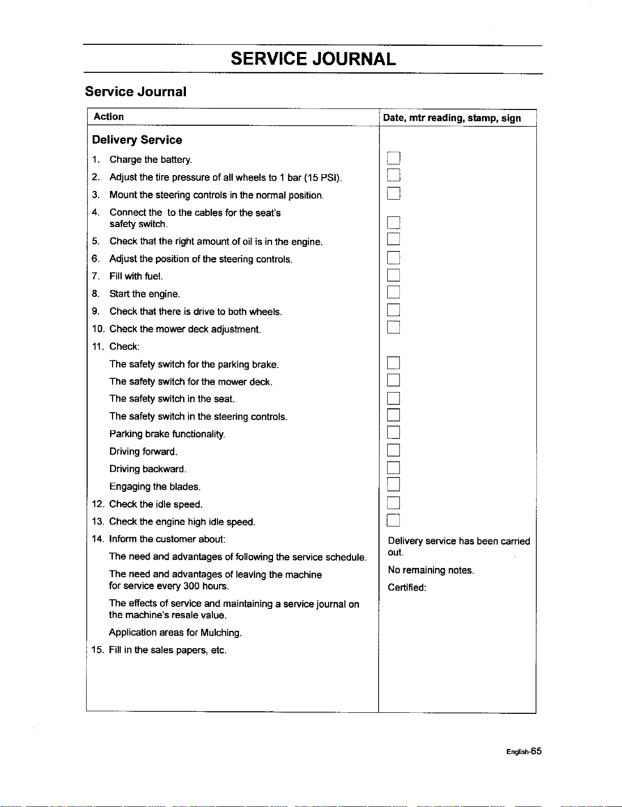
SERVICE JOURNAL
Service Journal
Action Date, mtr reading, stamp, sign
Delivery Service
1. Charge the battery.
2. Adjustthe tire pressure of all wheels to 1 bar (15 PSi).
3. Mountthe steeringcontrolsin the normal position.
4. Connectthe tothe cables forthe seat's
safety switch.
5. Check thatthe rightamountof oilis in the engine.
6. Adjustthe positionof the steeringcontrols.
7. Fillwith fuel
8. Startthe engine.
9. Check thatthere is driveto bothwheels.
10. Check the mower deck adjustment.
11. Check:
The safety switchfor the parkingbrake.
The safety switchfor the mower deck.
The safetyswitch in the seat.
The safety switchin the steeringcontrols.
Parkingbrake functionality.
Ddvingforward.
Driving backward.
Engaging the blades.
12. Check the idlespeed.
13. Check the engine high idlespeed.
14. Inform the customerabout:
The need and advantages offollowingtheservice schedule.
The need and advantages ofleaving the machine
for service every 300 hours.
The effectsof service and maintaininga servicejournal on
the machine'sresale value.
Applicationareas for Mulching.
15. Fill in thesales papers, etc.
[]
[]
[]
[]
[]
[]
[]
[]
[]
[]
[]
[]
[]
[]
[]
[]
[]
[]
[]
[]
Deliveryservice has been carded
out.
No remaining notes.
Certified:
English-65

SERVICE JOURNAL
After the First 5-8 Hours
1. Change engine oil. []
English-66
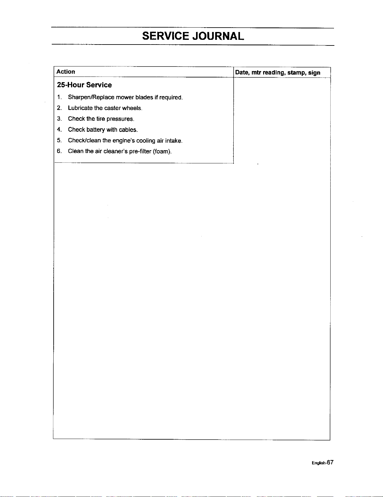
SERVICE JOURNAL
Date, mtr reading, stamp, sign
Action
25-Hour Service
1.
2.
3.
4.
5.
6.
Sharpen/Replaca mower blades if required.
Lubricatethe casterwheels.
Check the tire pressures.
Check batterywith cables.
Check/clean the engine's coolingair intake.
Clean the air cleaner's pre-filter(foam).
English-67
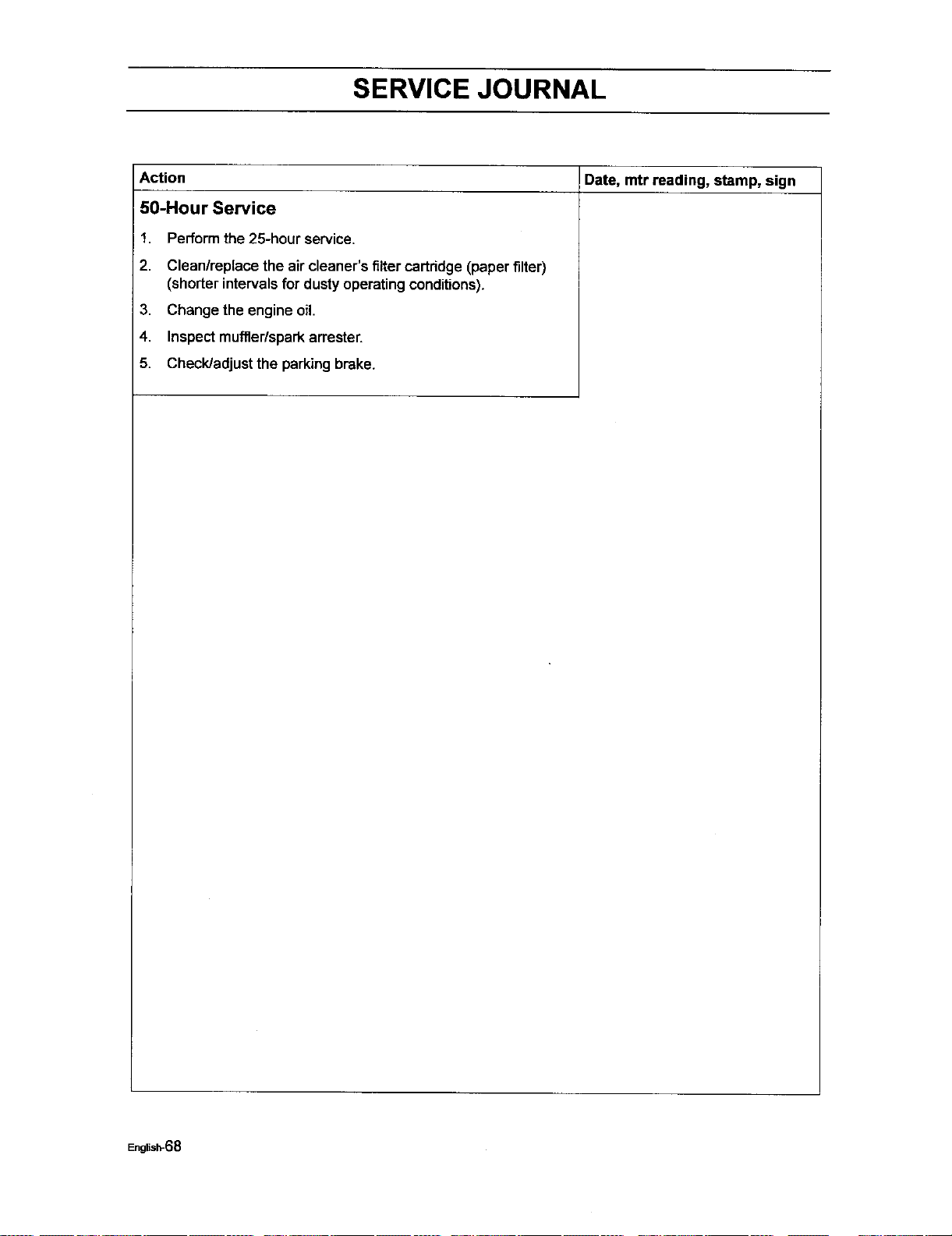
SERVICE JOURNAL
IDate, mtr reading, stamp, sign
Action
50-Hour Service
1.
2.
3.
4.
5.
Perform the 25-hour service.
Clean/replace the air cleaner'sfilter cartridge(paper filter)
(shorterintervalsfor dusty operatingconditions).
Change the engine oil.
Inspectmuffler/sparkarrester.
Check/adjustthe parkingbrake.
English-68
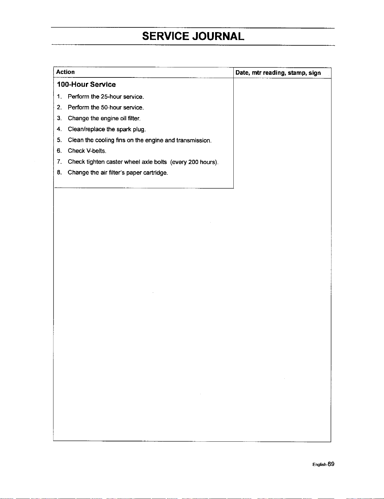
SERVICE JOURNAL
Date, mtr reading, stamp, sign
Action
100-Hour Service
1.
2.
3.
4.
5.
6,
7.
8.
Perform the 25-hour service.
Performthe 50-hour service.
Change the engine oil filter.
Clean/replace the spark plug.
Clean the coolingfins on the engine and transmission.
Check V-belts.
Check tighten casterwheel axle bolts (every200 hours).
Change the air filter's papercartridge.
English-69
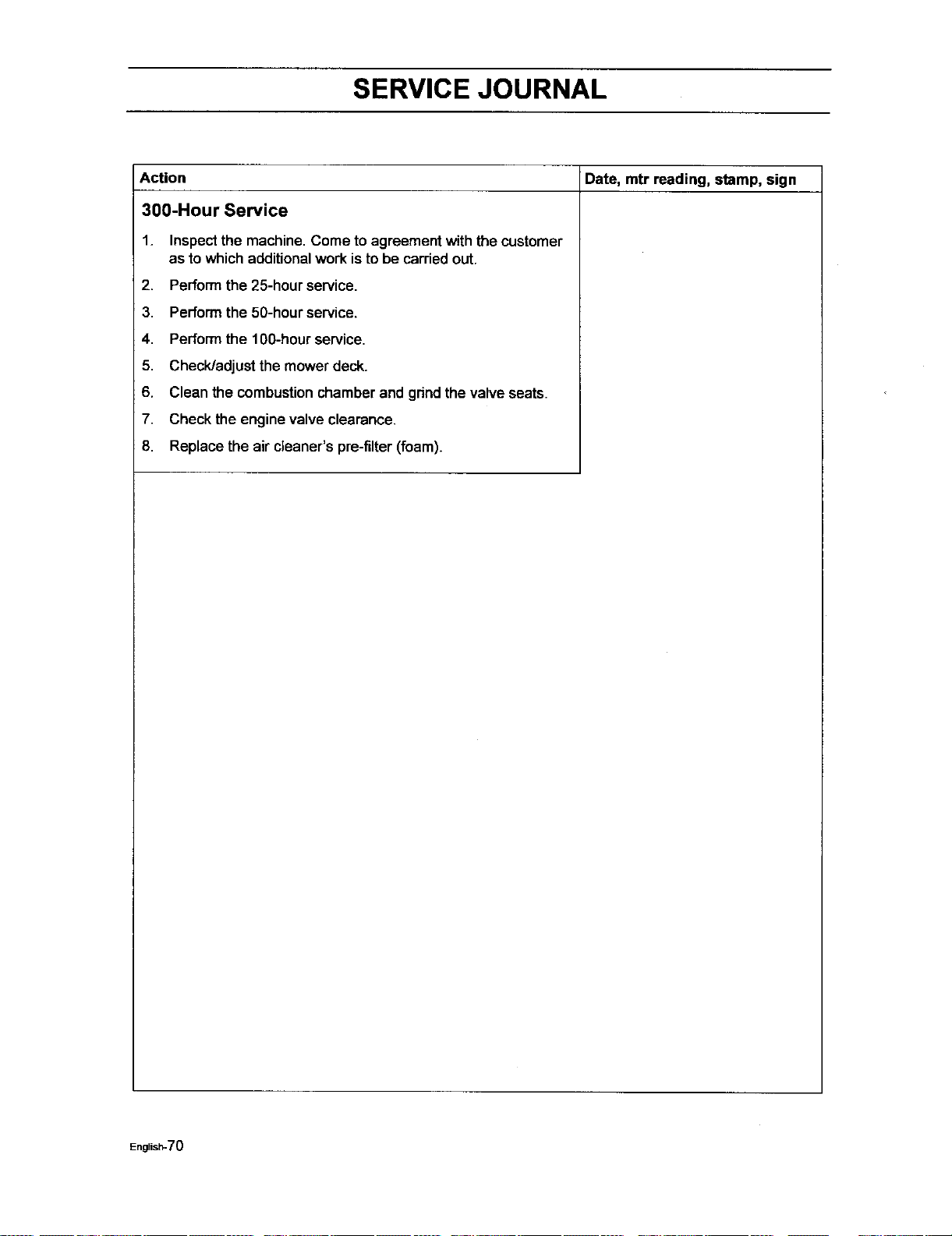
SERVICE JOURNAL
Date, mtr reading, stamp, sign
Action
300-Hour Service
1. Inspectthe machine, Come toagreement with the customer
as to which additionalwork isto be carried out.
2. Perform the 25-hour service.
3. Performthe 50-hourservice.
4. Performthe 100-hourservice.
5. Check/adjust the mower deck.
6. Clean the combustionchamber and grindthe valve seats.
7. Check the engine valve clearance.
8. Replace the air cleaner's pra-filter(foam).
English-70
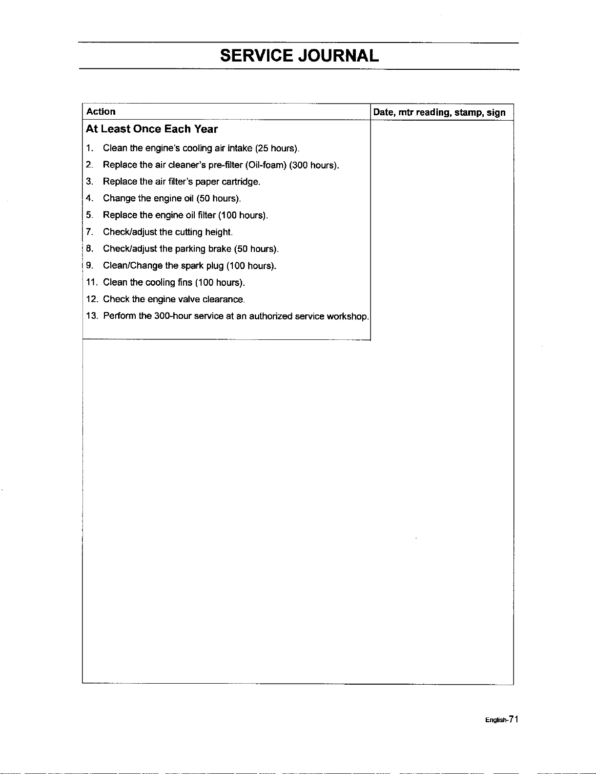
SERVICE JOURNAL
Action Date, mtr reading, stamp, sign
At Least Once Each Year
1. Clean the engine's cooling air intake (25 hours).
2. Replace the air cleaner's pre-filter (Oil-foam) (300 hours).
3. Replace the air filter's paper cartridge.
4. Change the engine oil(50 hours).
5. Replace the engine oil filter (100 hours),
7. Check/adjust the cutting height.
8. Check/adjust the parking brake (50 hours).
9. Clean/Change the spark plug (100 hours).
11. Clean the cooling fins (100 hours).
12. Check the engine valve clearance.
13. Perform the 300-hour serviceat an authorizedserviceworkshop.
English-71

112690Rir 11/08/05