Hqvarn
TT
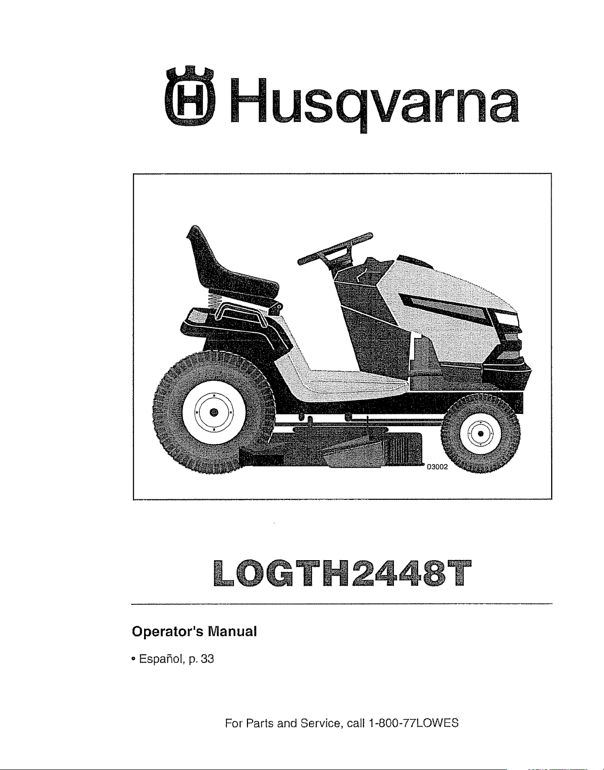
Operator's Manual
•Espafiol, p. 33
For Parts and Service, call 1-800-77LOWES
_DANGER: This cutting machine is capable of amputating hands and feet and
throwing objects. Failure to observe the following safety instructions could result
in serious injury or death.
_WARNING: in order to prevent ac-
cidental starting when setting up, trans-
porting, adjusting or making repairs,
always disconnect spark plug wire and
place wire where it cannot contact spark
plug.
_kWARNING: Do not coast down a hill in
neutral, you may lose control of the tractor.
_WARNING: Tow only the attachments
that are recommended by and comply with
specifications of the manufacturer of your
tractor. Use common sense when towing.
Operate only at the lowest possible speed
when on a slope. Too heavy of a load,
while on a slope, is dangerous. Tires can
lose traction with the ground and cause
you to lose control of your tractor.
_WARNING." Engine exhaust, some of
its constituents, and certain vehicle com-
ponents contain or emit chemicals known
to the State of California to cause cancer
and birth defects or other reproductive
harm.
_,WARNING: Battery posts, terminals
and related accessories contain lead and
lead compounds, chemicals known to the
State of California to cause cancer and
birth defects or other reproductive harm°
Wash hands after handling.
I. GENERAL OPERATION
o Read, understand, and follow all
instructions on the machine and in the
manual before starting.
° Do not put hands or feet near rotating
parts or under the machine° Keep clear
of the discharge opening at all times.
° Only allow responsible adults, who are
familiar with the instructions, to operate
the machine.
o Clear the area of objects sucll as
rocks, toys, wire, etc., which could be
picked up and thrown by the blades.
,, Be sure the area is clear of bystand-
ers before operating. Stop machine if
anyone enters the area.
°Never carry passengers,
° Do not mow in reverse unless abso-
lutely necessary° Always look down
and behind before and while backing.
o Never direct discharged material
toward anyone_ Avoid discharging
material against a wall or obstruction.
Material may ricochet back toward the
operator° Stop the blades when cross-
ing gravel surfaces.
, Do not operate machine without the
entire grass catcher, discharge guard,
or other safety devices in place and
working.
= Slowdown before turning.
° Never leave a running machine
unattended. Always turn off blades,
set parking brake, stop engine, and
remove keys before dismounting.
• Disengage blades when not mowing_
Shut off engine and wait for all parts to
come to a complete stop before clean-
ing the machine, removing the grass
catcher, or unclogging the discharge
guard_
° Operate machine only in daylight or
good artificial lighL
° Do not operate the machine while
under the influence of alcohol or drugs.
° Watch for traffic when operating near
or crossing roadways.
° Use extra care when loading or unload-
ing the machine into a trailer or truck,
°Always wear eye protection when oper-
ating machine.
° Data indicates that operators, age 60
years and above, are involved in a
large percentage of riding mower-re-
lated injuries. These operators should
evaluate their ability to operate the
riding mower safely enough to protect
themselves and others from serious
injury°
° Follow the manufacturer's recommen-
dation for wheel weights or counter-
weights.
°Keep machine free of grass, leaves
or other debris buitdoup which can
touch hot exhaust /engine parts and
burn, Do not allow the mower to plow
leaves or other debris which can cause
build-up to occur. Clean any oil or fuel
spillage before operating or storing the
machine_ Allow machine to cool before
storage°
2

!1. SLOPE OPERATION
Slopes are a major factor related to loss of
control and tip-over accidents, which can
result in severe injury or death_ Opera-
tion on all slopes requires extra caution, tf
you cannot back up the slope or if you feel
uneasy on it, do not mow it.
° Mow up and down slopes, not across.
• Watch for holes, ruts, bumps, rocks, or
other hidden objects. Uneven terrain
could overturn the machine. Tall grass
can hide obstacles.
• Choose a low ground speed so that
you will not have to stop or shift while
on the slope.
• Do not mow on wet grass.Tires may
lose traction.
Always keep the machine in gear when
going down slopes. Do not shift to
neutral and coast downhill_
° Avoid starting, stopping, or turning on
a slope. If the tires lose traction, dis-
engage the blades and proceed slowly
straight down the slope.
° Keep all movement on the slopes slow
and gradual Do not make sudden
changes in speed or direction, which
could cause the machine to roll over_
• Use extra care while operating ma-
chine with grass catchers or other at-
tachments; they can affect the stability
of the machine. Do no use on steep
slopes.
• Do not try to stabilize the machine by
putting your foot on the ground.
• Do not mow near drop-offs, ditches,
or embankments The machine could
suddenly roll over if a wheel is over the
edge or if the edge caves in.
Iii. CHILDREN
Tragic accidents can occur if the operator
is not alert to the presence of children.
Children are often attracted to the machine
and the mowing activity. Never assume
that children will remain where you last
saw them.
° Keep children out of the mowing area
and in the watchful care of a respon-
sible adult other than the operator.
• Be alert and turn machine off if a child
enters the area_
° Before and while backing, look beilind
and down for small children°
o Never carry children, even with the
blades shut off. They may fall off and
be seriously injured or interfere with
safe machine operation. Children who
have been given rides in the past may
suddenly appear in the mowing area
for another ride and be run over or
backed over by the machine.
. Never allow children to operate the
machine.
° Use extra care when approaching blind
corners, shrubs, trees, or other objects
that may block your view of a child
IV. TOWING
° Tow only with a machine that has a
hitch designed for towing. Do not at-
tach towed equipment except at the
hitch point.
• Follow the manufacturer's recom-
mendation for weight limits for towed
equipment and towing on slopes°
• Never allow children or others in or on
towed equipment.
° On slopes, the weight of the towed
equipment may cause loss of traction
and loss of control.
° Travel slowly and allow extra distance
to stop.
V. SERVICE
SAFE HANDLING OF GASOLINE
To avoid personal injury or property
damage, use extreme care in handling
gasoline_ Gasoline is extremely flammable
and the vapors are explosive_
• Extinguish all cigarettes, cigars, pipes,
and other sources of ignition.
• Use only approved gasoline container_
o Never remove gas cap or add fuel with
the engine running. Allow engine to
cool before refueling_
• Never fuel the machine indoors.
o Never store the machine or fuel con-
tainer where there is an open flame,
spark, or pilot light such as on a water
heater or other appliances_
° Never fill containers inside a vehicle
or on a truck or trailer bed with plastic
liner. Always place containers on the
ground away from your vehicle when
filling,.
3
• Remove gas-powered equipment from
the truck or trailer and refuel it on the
ground. If this is not possible, then
refuel such equipment with a portable
container, rather than from a gasoline
dispenser nozzle.
• Keep the nozzle in contact with the rim
of the fuel tank or container opening at
all times until fueling is complete., Do
not use a nozzle lock-open device°
° if fuel is spilled on clothing, change
clothing immediately°
• Never overfill fuel tank. Replace gas
cap and tighten securely.
GENERAL SERVICE
° Never operate machine in a closed
area,
. Keep all nuts and bolts tight to be sure
the equipment is in safe working condi-
tion.
• Never tamperwith safety devices.
Check their proper operation regularly.
° Keep machine free of grass, leaves, or
other debris build-up. Clean oil or fuel
spillage and remove any fuel-soaked
debris. Allow machine to cool before
storing.
° If you strike a foreign object, stop and
inspect the machine,, Repair, if neces-
sary, before restarting,
° Never make any adjustments or repairs
with the engine running.
° Check grass catcher components and
the discharge guard frequently and
replace with manufacturer's recom-
mended parts, when necessary,
• Mower blades are sharp. Wrap the
blade or wear gloves, and use extra
caution when servicing them.
° Check brake operation frequently, Ad-
just and service as required.
° Maintain or replace safety and instruc-
tion labels, as necessary.
o Be sure the area is clear of bystand-
ers before operating. Stop machine if
anyone enters the area.
o Never carry passengers.
o Do not mow in reverse unless abso-
lutely necessary. Always look down
and behind before and while backing°
o Never carry children, even with the
blades shut off. They may fall off and
be seriously injured or interfere with
safe machine operation. Children who
have been given rides in the past may
suddenly appear in the mowing area
for another ride and be run over or
backed over by the machine.
• Keep children out of the mowing area
and in the watchful care of a respon-
sible adult other than the operator°
• Be alert and turn machine off if a child
enters tile area.
° Before and while bacldng, look behind
and down for small children.
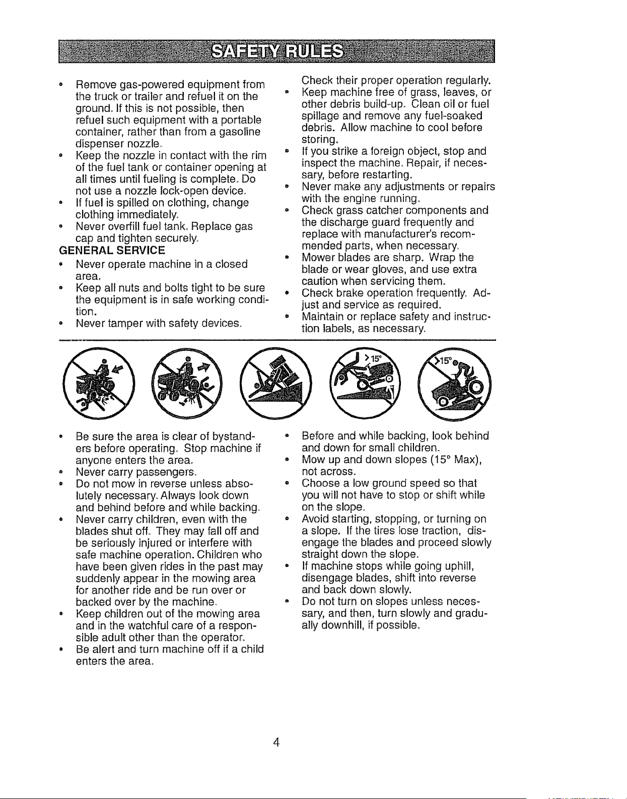
° Mow up and down slopes (15 ° Max),
not across.
o Choose a low ground speed so that
you will not have to stop or shift while
on the slope.
• Avoid starting, stopping, or turning on
a slope. If the tires lose traction, dis-
engage the blades and proceed slowly
straight down the slope.
° If machine stops while going uphill,
disengage blades, shift into reverse
and back down slowly.
, Do not turn on slopes unless neces-
sary, and then, turn slowly and gradu-
ally downhill, if possible.
4
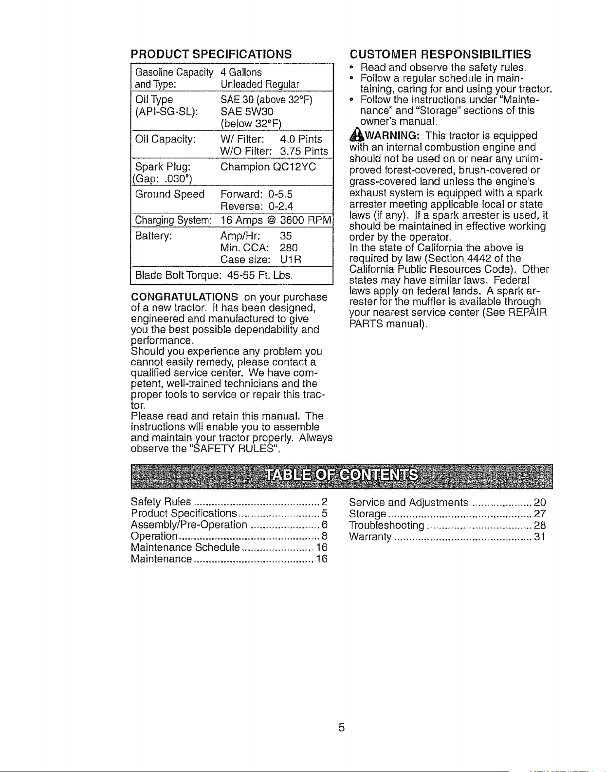
PRODUCT SPECIFICATIONS
Gasoline Capacity 4 Gallons
and Type: Unleaded Regular
Oil Type SAE 30 (above 32°F)
(API-SG-SL): SAE 5W30
(below 32°F)
Oil Capacity: VV! Filter: 4.0 Pints
W/O Filter: 3.75 Pints
Spark Plug: Champion QC12YC
(Gap: .030")
Ground Speed Forward: 0-5.5
Reverse: 0-2.4
Charging System: 16 Amps @ 3600 RPM
Battery: Amp/Hr: 35
Min, CCA: 280
Case size: UIR
Blade Bolt Torque: 45-55 Ft. Lbs.
CONGRATULATIONS on your purchase
of a new tractor. It has been designed,
engineered and manufactured to give
you the best possible dependability and
performance.
Should you experience any problem you
cannot easily remedy, please contact a
qualified service center. We have com-
petent, well-trained technicians and tile
proper tools to service or repair this trac-
tor.
Please read and retain this manual. The
instructions will enable you to assernble
and maintain your tractor properly. Always
observe the "SAFETY RULES",
CUSTOMER RESPONSIBILITIES
o Read and observe the safety rules.
• Follow a regular schedule in main-
taining, caring for and using your tractor,,
°Follow the instructions under"Mainte-
nance" and "Storage" sections of this
owner's manual.
,_WARNING: This tractor is equipped
with an internal combustion engine and
should not be used on or near any unim-
proved forest-covered, brush-covered or
grass-covered land unless the engine's
exhaust system is equipped with a spark
arrester meeting applicable local or state
laws (if any)_ If a spark arrester is used, it
should be maintained in effective working
order by the operator.
In the state of California the above is
required by law (Section 4442 of the
California Public Resources Code). Other
states may have similar laws. Federal
laws apply on federal lands. A spark ar-
rester for the muffler is available through
your nearest service center (See REPAIR
PARTS manual).
Safety Rules .......................................... 2
Product Specifications ........................... 5
Assembly/Pre-Operation ........................ 6
Operation ................................................ 8
Maintenance Schedule .......................... 16
Maintenance ........................................ 16
Service and Adjustments ..................... 20
Storage ................................................ 27
Troubleshooting ..................................... 28
Warranty ............................................... 31
5
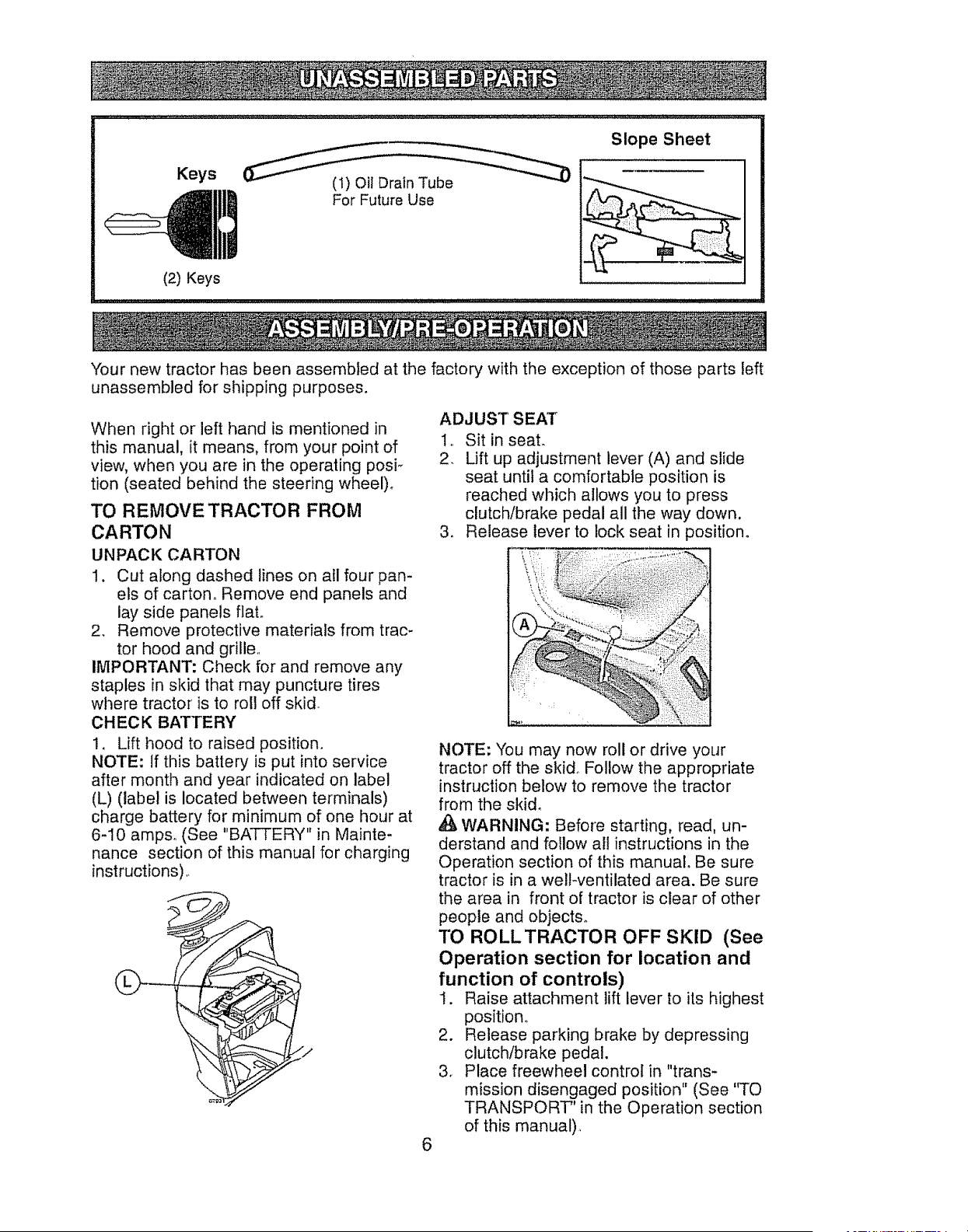
Slope Sheet
Keys
qlll',l
(2) Keys
(1) Oil Drain Tube
For Future Use
Your new tractor has been assembled at the factory with the exception of those parts left
unassembled for shipping purposes.
When right or left hand is mentioned in
this manual, it means, from your point of
view, when you are in the operating posF
tion (seated behind the steering wheel).
TO REMOVE TRACTOR FROM
CARTON
UNPACK CARTON
1. Cut along dashed lines on all four pan-
els of carton° Remove end panels and
lay side panels flat,
2, Remove protective materials from trac-
tor hood and grille,
IMPORTANT: Check for and remove any
staples in skid that may puncture tires
where tractor is to ro!l off skid
CHECK BATTERY
!, Lift hood to raised position.
NOTE: if this battery is put into service
after month and year indicated on label
(L) (label is located between terminals)
charge battery for minimum of one hour at
6-10 amp& (See "BATTERY" in Mainte-
nance section of this manual for charging
instructions)
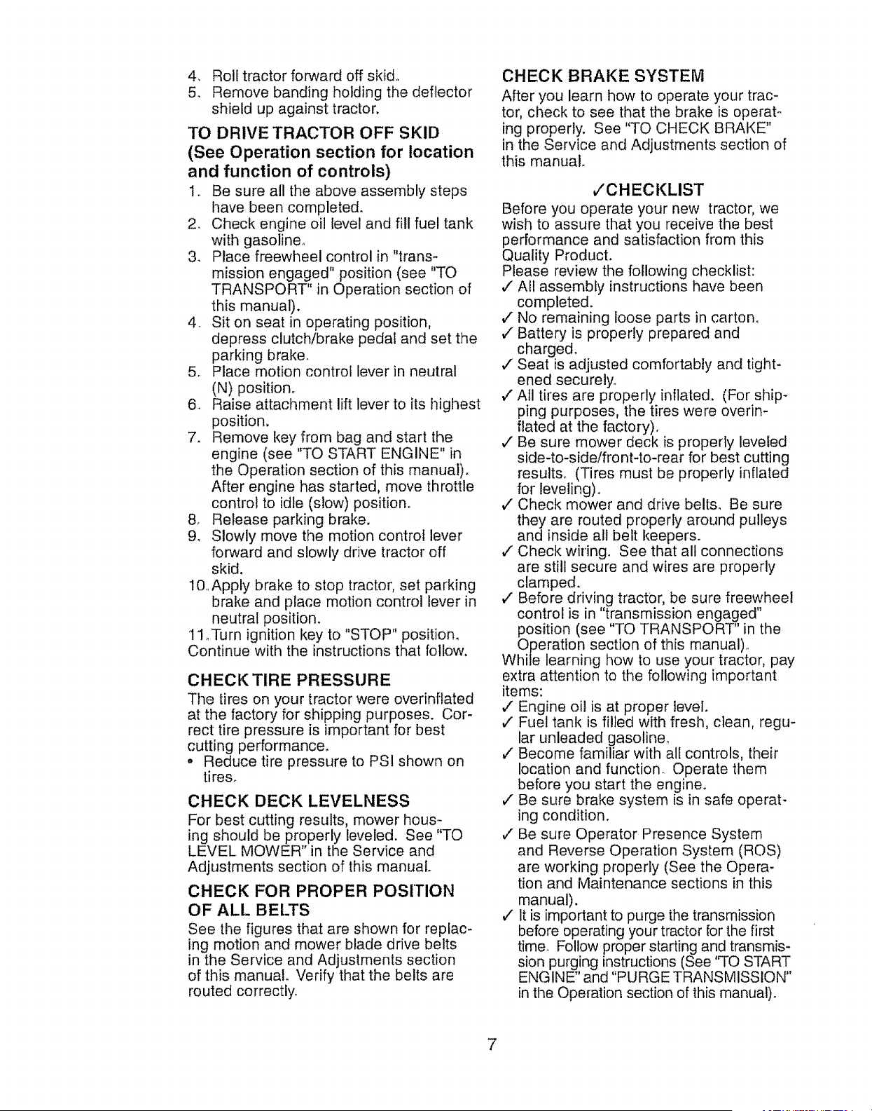
ADJUST SEAT
1, Sit in seat.
2. Lift up adjustment lever (A) and slide
seat until a comfortable position is
reached which allows you to press
clutch/brake pedal all the way down.
3. Release lever to lock seat in position°
6
NOTE: You may now roll or drive your
tractor off the skid Follow the appropriate
instruction below to remove the tractor
from the skid,
WARNING: Before starting, read, un-
derstand and follow all instructions in the
Operation section of this manual. Be sure
tractor is in a welkventilated area. Be sure
the area in front of tractor is clear of other
people and objects°
TO ROLL TRACTOR OFF SKID (See
Operation section for location and
function of controls)
1. Raise attachment lift lever to its highest
position.
2. Release parking brake by depressing
clutch/brake pedal.
3. Place freewheel control in "trans-
mission disengaged position" (See "TO
TRANSPORT" in the Operation section
of this manual).
4. Rolltractorforwardoff skid°
5. Removebandingholdingthedeflector
shieldup againsttractor,
TO DRIVE TRACTOR OFF SKID
(See Operation section for location
and function of controls)
1, Be sure all the above assembly steps
have been completed.
2. Check engine oil level and fill fuel tank
with gasoline_
3. Place freewheel control in "trans-
mission engaged" position (see "TO
TRANSPORT" in Operation section of
this manual).
4 Sit on seat in operating position,
depress clutch/brake pedal and set the
parking brake.
5, Place motion control lever in neutral
(N) position,,
6_ Raise attachment lift lever to its highest
position.
7. Remove key from bag and start the
engine (see "TO START ENGINE" in
the Operation section of this manual).
After engine has started, move throttle
control to idle (stow) position°
8_ Release parking brake,
9. Slowly move the motion control lever
forward and slowly drive tractor off
skid.
10,Apply brake to stop tractor, set parking
brake and place motion control lever in
neutral position.
11 _Turn ignition key to "STOP" position.
Continue with the instructions that follow.
CHECK TIRE PRESSURE
Tile tires on your tractor were overinflated
at the factory for shipping purposes. Cor-
rect tire pressure is important for best
cutting performance.
,, Reduce tire pressure to PSI shown on
tires.
CHECK DECK LEVELNESS
For best cutting results, mower hous -
ing should be properly leveled. See "TO
LEVEL MOWER" in the Service and
Adjustments section of this manual°
CHECK FOR PROPER POSITION
OF ALl. BELTS
See the figures that are shown for replac-
ing motion and mower blade drive belts
in the Service and Adjustments section
of this manual. Verify that the belts are
routed correctly.
CHECK BRAKE SYSTEM
After you learn how to operate your trac-
tor, check to see that the brake is operato
ing properly. See "TO CHECK BRAKE"
in the Service and Adjustments section of
this manual_
v'CHECKLIST
Before you operate your new tractor, we
wish to assure that you receive the best
performance and satisfaction from this
Quality Product.
Please review the following checklist:
v" All assembly instructions have been
completed.
v" No remaining loose parts in carton°
,/Battery is properly prepared and
charged.
,/Seat is adjusted comfortably and tight-
ened securely.
v" All tires are properly inflated. (For ship-
ping purposes, the tires were overin-
fiated at the factory),
,/Be sure mower deck is properly leveled
side-to-side/front-to-rear for best cutting
results. (Tires must be properly inflated
for leveling).
J" Check mower and drive belts. Be sure
they are routed properly around pulleys
and inside all belt keepers.
¢" Check wiring. See that all connections
are still secure and wires are properly
clamped.
J" Before driving tractor, be sure freewheel
control is in "transmission engaged"
position (see "TO TRANSPORT" in the
Operation section of this manual),
While learning how to use your tractor, pay
extra attention to the following important
items:
J Engine oil is at proper level.
J Fuel tank is filled with fresh, clean, regu-
lar unleaded gasoline_
v" Become familiar with all controls, their
location and function. Operate them
before you start the engine°
v" Be sure brake system is in safe operat-
ing condition.
J Be sure Operator Presence System
and Reverse Operation System (ROS)
are working properly (See the Opera-
tion and Maintenance sections in this
manual).
¢ It is important to purge the transmission
before operating your tractor for the first
time_ Follow proper starting and transmis-
sion purging instructions (See '%0 START
ENGINE" and "PURGE TRANSMISSION"
in the Operation section of this manual)°
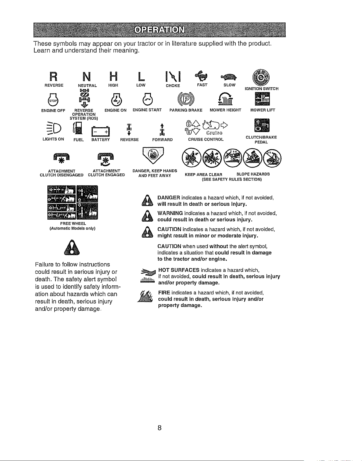
Thesesymbolsmayappearon yourtractoror in literaturesuppliedwith the product.
Learnand understandtheir meaning.,
R N H LJXJ
REVERSE NEUTRAL HIGH LOW CHOKE FAST SLOW
ENGINE OFF REVERSE ENGINE ON ENGINE START PARKING BRAKE MOWER HEIGHT
OPERATION
SYSTEM (ROS)
LIGHTS ON FUEL
;r
t
BATTERY REVERSE FORWARD
®$ 62, o
CRUISECO.TRO"
@
IGNITION SWITCH
MOWER LIFT
CLUTCH/BRAKE
PEDAL
ATTACHMENT ATTACHMENT
CLUTCH DISENGAGED CLUTCH ENGAGED
DANGER, KEEP HANDS
AND FEET AWAY
®@®@@
KEEP AREA CLEAR SLOPE HAZARDS
(SEE SAFETY RULE_ SECTION)
FREE WHEEL
(Automatic Models only')
DANGER indicates a hazard which, if not avoided,
will result In death or serious Injury.
WARNING indicates a hazard which, if not avoided,
could result in death or serious injury.
Failure to follow instructions
could result in serious injury or
death, The safety alert symbol
is used to identify safety inform-
ation about hazards which can
result in death, serious injury
and/or property damager
&
i=====_=1
CAUTION indicates a hazard which, if not avoided,
might result in minor or moderate injury.
CAUTION when used without the alert symbol,
indicates a situation that could result in damage
to the tractor andlor engine.
HOT SURFACES indicates a hazard which,
if not avoided, could result In death, serious injury
and/or property damage.
FIRE indicates a hazard which, it' not avoided,
could result in death, serious injury andlor
property damage.
8
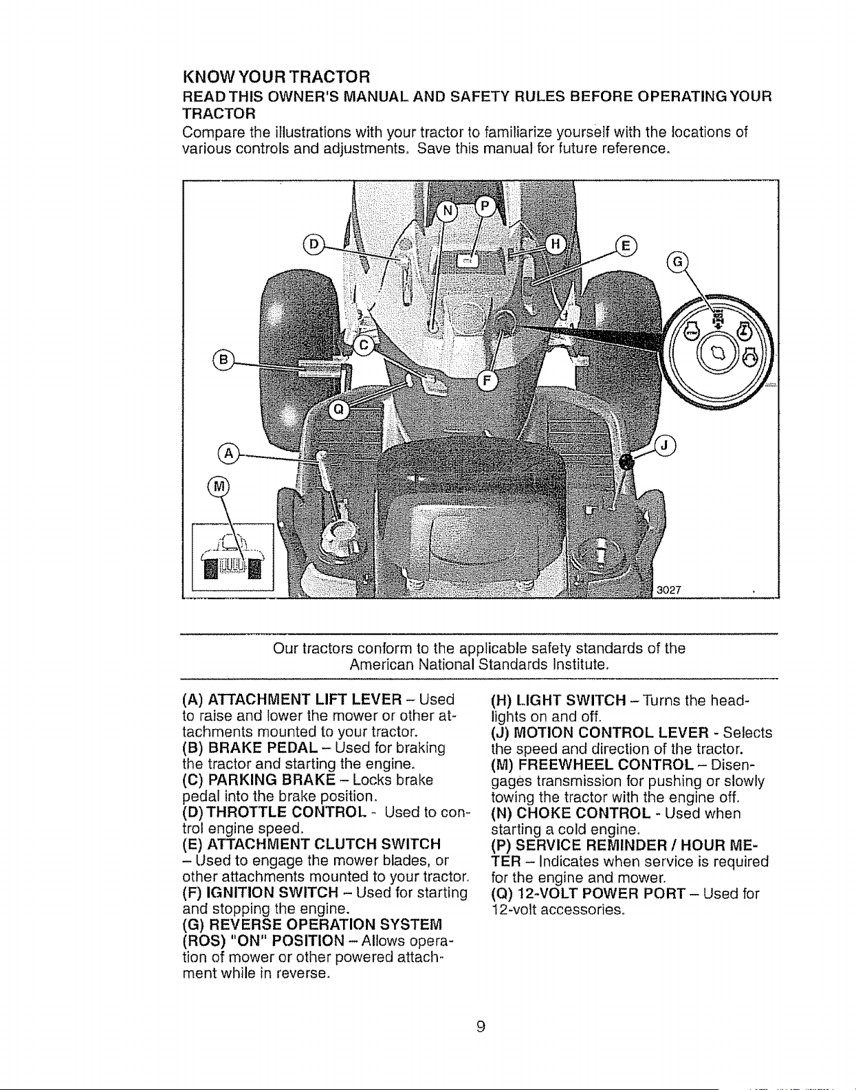
KNOW YOUR TRACTOR
READ THIS OWNER'S MANUAL AND SAFETY RULES BEFORE OPERATING YOUR
TRACTOR
Compare the illustrations with your tractor to familiarize yourself with the locations of
various controls and adjustments, Save this manual for future reference,
3027
Our tractors conform to the applicable safety standards of the
American National Standards Institute.
(A) ATTACHMENT LIFT LEVER - Used
to raise and lower the mower or other at-
tachments mounted to your tractor.
(B) BRAKE PEDAL - Used for braking
the tractor and starting the engine.
(C) PARKING BRAKE -Locks brake
pedal into the brake position.
(D) THROTTLE CONTROL - Used to con-
trol engine speed.
(E) ATTACHMENT CLUTCH SWITCH
- Used to engage the mower blades, or
other attachments mounted to your tractor_
(F) IGNITION SWITCH - Used for starting
and stopping the engine.
(G) REVERSE OPERATION SYSTEM
(ROS) "ON" POSITION - Allows opera-
tion of mower or other powered attach-
ment while in reverser
(H) tJGHT SWITCH -Turns the head-
lights on and off.
(J) MOTION CONTROL LEVER - Selects
the speed and direction of the tractor.
(M) FREEWHEEL CONTROL - Disen-
gages transmission for pushing or slowly
towing the tractor with the engine off,
(N) CHOKE CONTROL -Used when
starting a cold engine.
(P) SERVICE REMINDER/HOUR ME-
TER - Indicates when service is required
for the engine and mower.
(Q) 12-VOLT POWER PORT - Used for
12-volt accessories.
9
The operation of any tractor can result in foreign objects thrown into the
eyes, which can result in severe eye damage, Always wear safety glasses
or eye shields while operating your tractor or performing any adjustments
or repairs. We recommend standard safety glasses or a wide vision safety
mask worn over spectacles,
HOW TO USE YOUR TRACTOR
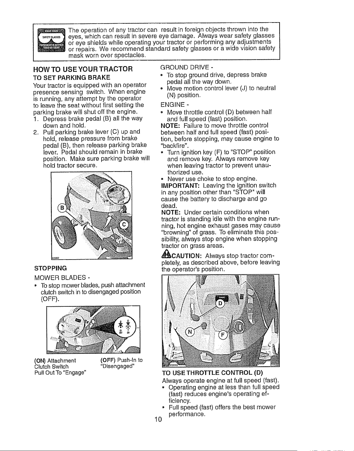
TO SET PARKING BRAKE
"tour tractor is equipped with an operator
presence sensing switcl!. When engine
is running, any attempt by the operator
to leave the seat without first setting the
parking brake will shut off the engine.
1_ Depress brake pedal (B) all the way
down and hold..
2. Pull parking brake lever (C) up and
hold, release pressure from brake
pedal (B), then release parking brake
lever. Pedal should remain in brake
position° Make sure parking brake will
hold tractor secure°
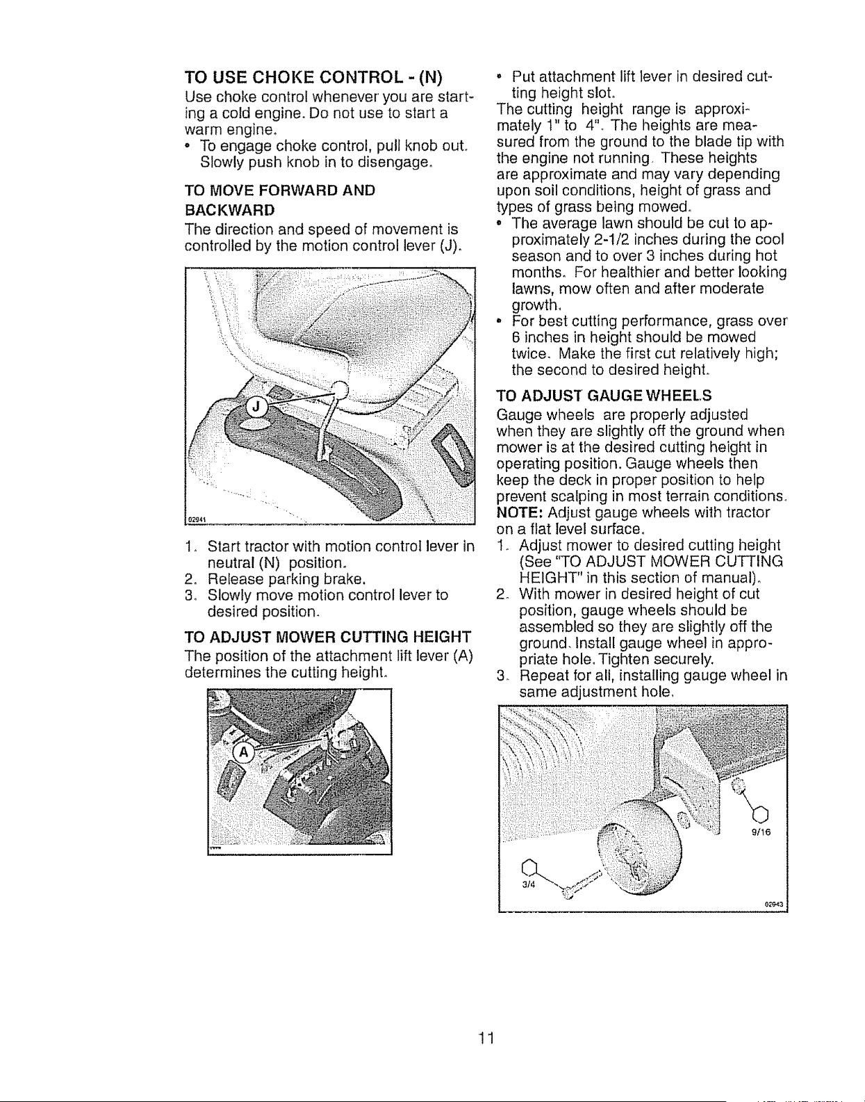
STOPPING
MOWER BLADES -
° To stop mower blades, push attachment
clutch switch in to disengaged position
(OFF).
GROUND DRIVE-
• To stop ground drive, depress brake
pedal all the way down.
. Move motion control lever (J) to neutral
(N) position.
ENGINE -
• Move throttle control (D) between half
and full speed (fast) position.
NOTE: Failure to move throttle control
between half and ful! speed (fast) posi-
tion, before stopping, may cause engine to
"backfire".
• Turn ignition key (F) to "STOP" position
and remove key. Always remove key
when leaving tractor to prevent unau-
thorized use,
o Never use choke to stop engine.
IMPORTANT: Leaving the ignition switch
in any position other than "STOP" will
cause the battery to discharge and go
dead,
NOTE: Under certain conditions when
tractor is standing idle with the engine run-
ning, hot engine exhaust gases may cause
"browning" of grass. To eliminate this pos.-
sibility, always stop engine when stopping
tractor on grass areas.
_,CAUTION' Always stop tractor com-
pletely, as described above, before leaving
the operator's position.
(ON) Attachment
Clutch Switch
Pull Out To "Engage"
(OFF) Push-In to
"Disengaged"
°
10
TO USE THROTTLE CONTROL (D)
Always operate engine at full speed (fast).
° Operating engine at less than full speed
(fast) reduces engine's operating ef-
ficiency.
Full speed (fast) offers the best mower
performance.
TO USE CHOKE CONTROL - (N)
Use choke control whenever' you are start-
ing a cold engine. Do not use to start a
warm engine.
o To engage choke control, pull knob out.
Slowly push knob in to disengage°
TO MOVE FORWARD AND
BACKWARD
The direction and speed of movement is
controlled by the motion control lever (J)°
!_ Start tractor with motion control lever in
neutral (N) position.
2. Release parking brake.
3. Slowly move motion control lever to
desired position.
TO ADJUST MOWER CUTTING HEIGHT
The position of the attachment lift lever (A)
determines the cutting heighL
• Put attachment lift lever in desired cut-
ting height slot.
The cutting height range is approxi_
mately t" to 4"° The heights are mea-
sured from the ground to the blade tip with
the engine not running, These heights
are approximate and may vary depending
upon soil conditions, height of grass and
types of grass being mowed,.
• The average lawn should be cut to ap-
proximately 2-t/2 inches during the cool
season and to over 3 inches during hot
months. For healthier and better looking
lawns, mow often and after moderate
growth,
o For best cutting performance, grass over
6 inches in height should be mowed
twice. Make the first cut relatively high;
the second to desired height..
TO ADJUST GAUGE WHEELS
Gauge wheels are properly adjusted
when they are slightly off the ground when
mower is at the desired cutting height in
operating position. Gauge wheels then
keep the deck in proper position to help
prevent scalping in most terrain conditions,,
NOTE: Adjust gauge wheels with tractor
on a flat level surface.
I. Adjust mower to desired cutting height
(See "TO ADJUST MOWER CUTTING
HEIGHT" in this section of manual).
2_ With mower in desired height of cut
position, gauge wheels should be
assembled so they are slightly off the
ground. Install gauge wheel in appro-
priate hole. Tighten securely.
3. Repeat for all, installing gauge wheel in
same adjustment hole,
11
TO OPERATE MOWER
Your tractor is equipped with an operator
presence sensing switch. Any attempt
by the operator to leave the seat with the
engine running and the attachment clutch
engaged will shut off the engine.You must
remain fully and centrally positioned in the
seat to prevent the engine from hesitating
or cutting off when operating your equip-
ment on rough, rolling terrain or hills.
I. Select desired height of cut with at-
tachment lift lever.
2o Start mower blades by engaging at-
tachment clutch control.
TO STOP MOWER BLADES -
disengage attachment clutch control.
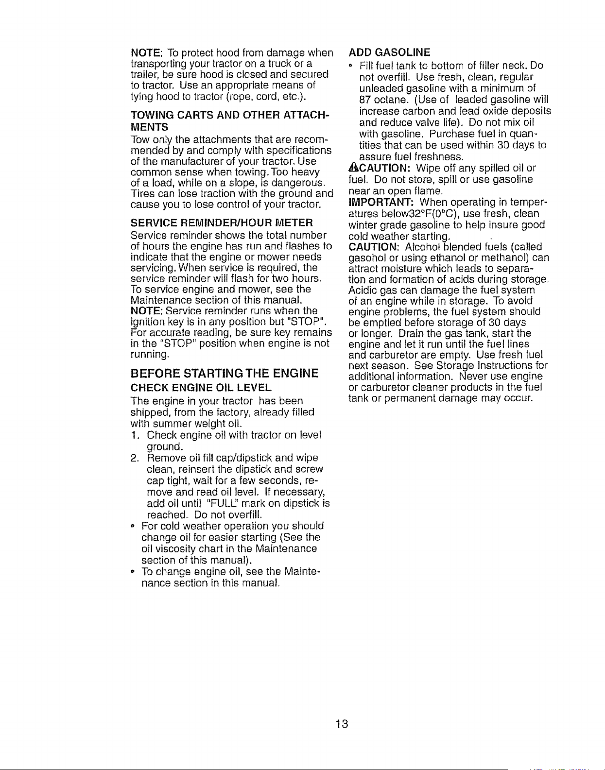
•b,CAUTION: Do not operate the mower
without either the entire grass catcher,
on mowers so equipped, or the deflector
shield (S)in place°
REVERSE OPERATION SYSTEM (ROS)
Your tractor is equipped with a Reverse
Operation System (ROS)° Any attempt by
the operator to travel in the reverse direc-
tion with the attachment clutch engaged
wilt shut off the engine unless ignition key
is placed in the ROS "ON" position.
_WARNING: Backing up with the at-
tachment clutch engaged while mowing
is strongly discouraged° _Jrning the ROS
"ON", to allow reverse operation with the
attachment clutch engaged, should only
be done when the operator decides it is
necessary to reposition the machine with
the attachment engaged, Do not mow in
reverse unless absolutely necessary.
USING THE REVERSE OPERATION
SYSTEM -
Only use if you are certain no children or
other bystanders will enter the mowing
area,
1, Move motion control lever to neutral
(N) position.
2, With engine running, turn ignition key
counterclockwise to ROS "ON" posi-
tion,
3. Look down and behind before and
while backing.
4. Slowly move motion control lever to
reverse (R) position to start movement,
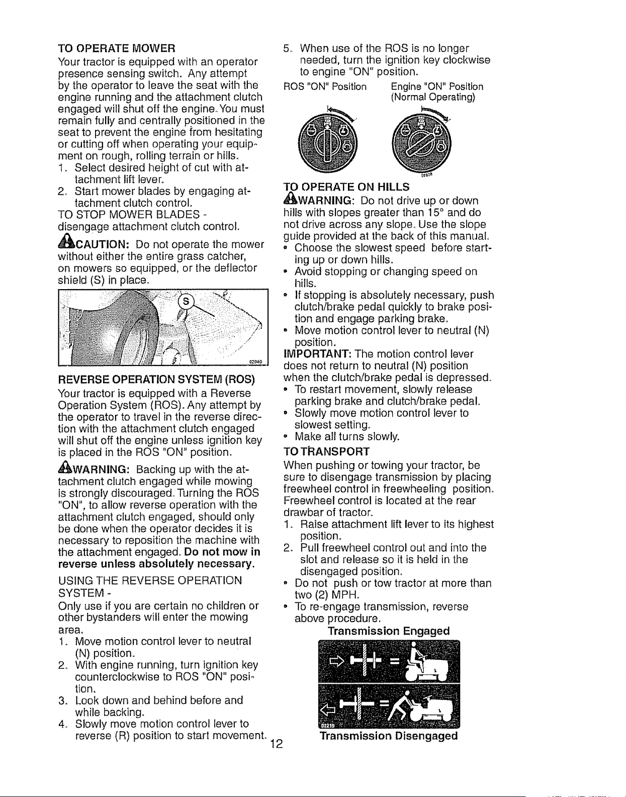
5. When use of the ROS is no longer
needed, turn the ignition key clockwise
to engine "ON" position.
ROS "ON" Position Engine "ON" Position
(Normal Operating)
'TO OPERATE ON HILLS
,_WARNING: Do not drive up or down
hills with slopes greater than 15 ° and do
not drive across any slope, Use the slope
guide provided at the back of this manual
o Choose the slowest speed before start-
ing up or down hills.
•Avoid stopping or changing speed on
hills.
° If stopping is absolutely necessary, push
clutch/brake pedal quickly to brake posi-
tion and engage parking brake.
° Move motion control lever to neutral (N)
position.
IMPORTANT: The motion control lever
does not return to neutral (N) position
when the clutch/brake pedal is depressed.
. To restart movement, slowly release
parking brake and clutch/brake pedal.
° Slowly move motion control lever to
slowest setting.
.Make all turns slowly.
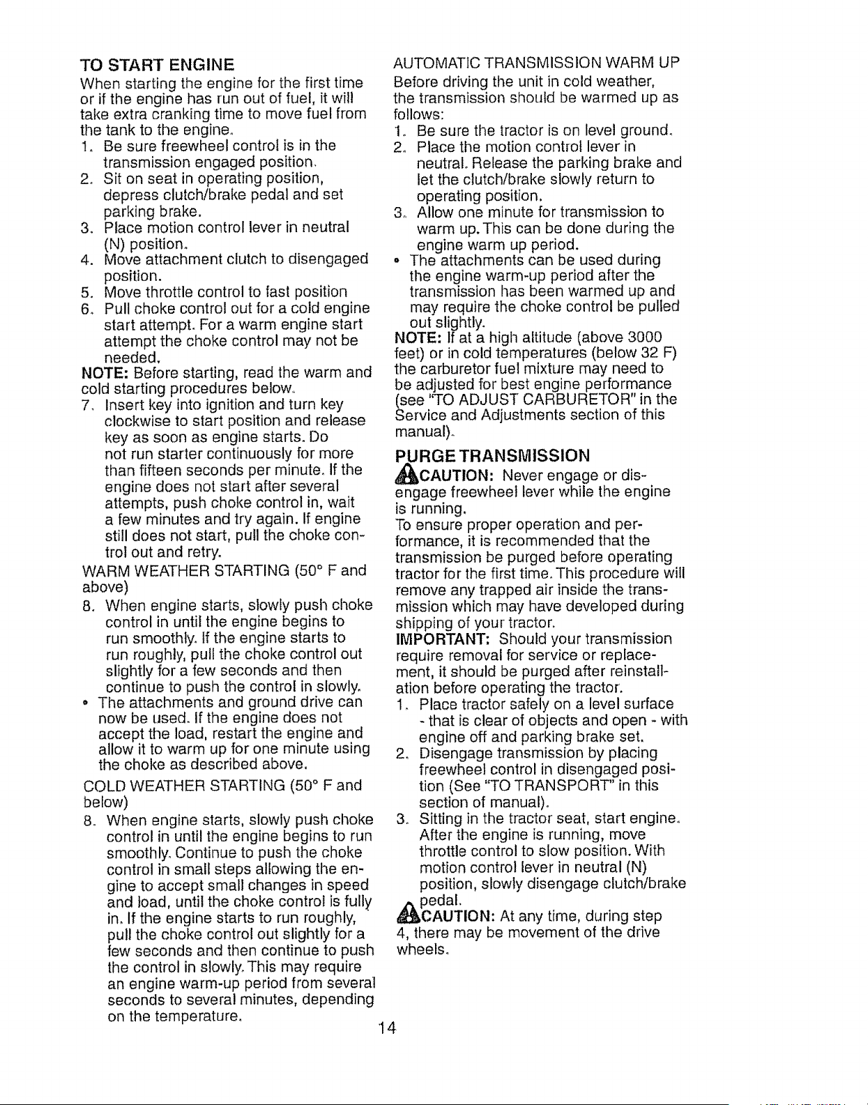
TO TRANSPORT
When pushing or towing your tractor, be
sure to disengage transmission by placing
freewheel control in freewheeling position,
Freewheel control is located at the rear
drawbar of tractor°
I. Raise attachment lift lever to its highest
position.
2. Pull freewheel control out and into the
slot and release so it is held in the
disengaged position.
° Do not push or tow tractor at more than
two (2) MPH.
° To re-engage transmission, reverse
above procedure.
Transmission Engaged
12 Transmission Disengaged
NOTE: To protect hood from damage when
transporting your tractor on a truck or a
trailer, be sure hood is closed and secured
to tractor. Use an appropriate means of
tying hood to tractor (rope, cord, etc.)o
TOWING CARTS AND OTHER ATTACH-
MENTS
Tow only the attachments that are recom-
mended by and comply with specifications
of the manufacturer of your tractor. Use
common sense when towing° Too heavy
of a load, while on a slope, is dangerous.
Tires can lose traction with the ground and
cause you to lose control of your tractor.
SERVICE REMINDERtHOUR METER
Service reminder shows the total number
of hours the engine has run and flashes to
indicate that the engine or mower needs
servicing. When service is required, the
service reminder will flash for two hours.
To service engine and mower, see the
Maintenance section of this manual
NOTE: Service reminder runs when the
ignition key is in any position but "STOP".
For accurate reading, be sure key remains
in the "STOP" position when engine is not
running_
BEFORE STARTING THE ENGINE
CHECK ENGINE OIL LEVEL
The engine in your tractor has been
shipped, from the factory, already filled
with summer weight oiio
1. Check engine oil with tractor on level
ground.
2. Remove oil fill cap/dipstick and wipe
clean, reinsert the dipstick and screw
cap tight, wait for a few seconds, re-
move and read oil level. If necessary,
add oil until "FULU' mark on dipstick is
reached_ Do not overfill.
• For cold weather operation you should
change oil for easier starting (See the
oil viscosity chart in the Maintenance
section of this manual).
° To change engine oil, see the Mainte-
nance section in this manual.
ADD GASOLINE
o Fill fuel tank to bottom of filler neck. Do
not overfill Use fresh, clean, regular
unleaded gasoline with a minimum of
87 octane. (Use of leaded gasoline will
increase carbon and lead oxide deposits
and reduce valve life)o Do not mix oil
with gasoline. Purchase fuel in quan _,
tities that can be used within 30 days to
assure fuel freshness.
_CAUTION" Wipe off any spilled oil or
fuel. Do not store, spill or use gasoline
near an open flame_
IMPORTANT: When operating in temper-
atures below32°F(0°C), use fresh, clean
winter grade gasoline to help insure good
cold weather starting.
CAUTION: Alcohol blended fuels (called
gasohol or using ethanol or methanol) can
attract moisture which leads to separa-
tion and formation of acids during storage_
Acidic gas can damage the fuel system
of an engine while in storage. To avoid
engine problems, the fuel system should
be emptied before storage of 30 days
or longer. Drain the gas tank, start the
engine and let it run until the fuel lines
and carburetor are empty. Use fresh fuel
next season. See Storage Instructions for
additional information. Never use engine
or carburetor cleaner products in the fuel
tank or permanent damage may occur.
13
TO START ENGINE
When starting the engine for the first time
or if the engine has run out of fuel, it will
take extra cranking time to move fuel from
the tank to the engine.
I_ Be sure freewheel control is in the
transmission engaged position,
2. Sit on seat in operating position,
depress clutch/brake pedal and set
parking brake.
3. Place motion control lever in neutral
(N) position°
4. Move attachment clutch to disengaged
position.
5. Move throttle control to fast position
6o Pull choke control out for a cold engine
start attempt. For a warm engine start
attempt the choke control may not be
needed.
NOTE: Before starting, read the warm and
cold starting procedures below,
7. Insert key into ignition and turn key
clockwise to start position and release
key as soon as engine starts. Do
not run starter continuously for more
than fifteen seconds per minute. If the
engine does not start after several
attempts, push choke control in, wait
a few minutes and try again. If engine
still does not start, pull the choke con-
trol out and retry.
WARM WEATHER STARTING (50 ° F and
above)
8. When engine starts, slowly push choke
control in until the engine begins to
run smoothly. If the engine starts to
run roughly, pull the choke control out
slightly for a few seconds and then
continue to push the control in slowly.
• The attachments and ground drive can
now be use& If the engine does not
accept the load, restart the engine and
allow it to warm up for one minute using
the choke as described above.
COLD WEATHER STARTING (50 ° F and
below)
8. When engine starts, slowly push choke
control in until the engine begins to run
smoothly. Continue to push the choke
control in small steps allowing the en-
gine to accept small changes in speed
and toad, until the choke control is fully
in. if the engine starts to run roughly,
pull the choke control out slightly for a
few seconds and tllen continue to push
the control in slowly. This may require
an engine warm-up period from several
seconds to several minutes, depending
on the temperature.
AUTOMATIC TRANSMISSION WARM UP
Before driving the unit in cold weather,
the transmission should be warmed up as
follows:
1. Be sure the tractor is on level ground_
2o Place the motion control lever in
neutral° Release the parking brake and
let the clutchlbrake slowly return to
operating position,
3o Allow one minute for transrnission to
warm up. This can be done during the
engine warm up period.
• The attachments can be used during
the engine warm-up period after the
transmission has been warmed up and
may require the choke control be pulled
out slightly.
NOTE: If at a high altitude (above 3000
feet) or in cold temperatures (below 32 F)
the carburetor fuel mixture may need to
be adjusted for best engine performance
(see "TO ADJUST CARBURETOR" in the
Service and Adjustments section of this
manual)_
PURGE TRANSMISSION
_,CAUTION: Never engage or dis-
engage freewheel lever while the engine
is running.
To ensure proper operation and per-
formance, it is recommended that the
transmission be purged before operating
tractor for the first time. This procedure will
remove any trapped air inside the trans-
mission which may have developed during
shipping of your tractor.
IMPORTANT: Should your transmission
require removal for service or replace-
ment, it should be purged after reinstall-
ation before operating the tractor.
I. Place tractor safely on a level surface
- that is clear of objects and open - with
engine off and parking brake set.
2. Disengage transmission by placing
freewheel control in disengaged posi-
tion (See "TO TRANSPORT" in this
section of manual)°
3o Sitting in the tractor seat, start engine.
After the engine is running, move
throttle control to slow position. With
motion control lever in neutral (N)
position, slowly disengage clutch/brake
_Pced alo
AUTION: At any time, during step
4, there may be movement of the drive
wheels.
14
4_ Move motion control lever to full
forward position and hold for five (5)
seconds_ Move lever to full reverse
position and hold for five (5) seconds.
Repeat this procedure three (3) times.
5. Move motion control lever to neutral
(N) position. Shutoff engine and set
parking brake.
6. Engage transmission by placing free-
wheel control in engaged position (See
"TO TRANSPORT" in this section of
manual).
7. Sitting in the tractor seat, start engine.
After the engine is running, move
throttle control to half (1/2) speed_
With motion control lever in neutral (N)
position, slowly disengage clutch/brake
pedal.
8. Slowly move motion control lever for-
ward, after the tractor moves approxi-
mately five (5) feet, slowly move motion
control lever to reverse position. After
the tractor moves approximately five
(5) feet return the motion control lever
to the neutral (N) position. Repeat this
procedure with the motion control lever
three (3) times°
Your transmission is now purged and now
ready for normal operation.
MOWiNGTIPS
• Tire chains cannot be used when tile
mower housing is attached to tractor.
° Mower should be properly leveled for
best mowing performance° See "TO
LEVEL MOWER HOUSING" in the
Service and Adjustments section of this
manual.
° The left hand side of mower should be
used for trimming.
° Drive so that clippings are discharged
onto the area that has already been
cut° Have the cut area to the right of
the tractor'. This will result in a more
even distribution of clippings and more
uniform cutting.
• When mowing large areas, start by
turning to the right so that clippings will
discharge away from shrubs, fences,
driveways, etc. After one or two rounds,
mow in the opposite direction making
left hand turns until finished o
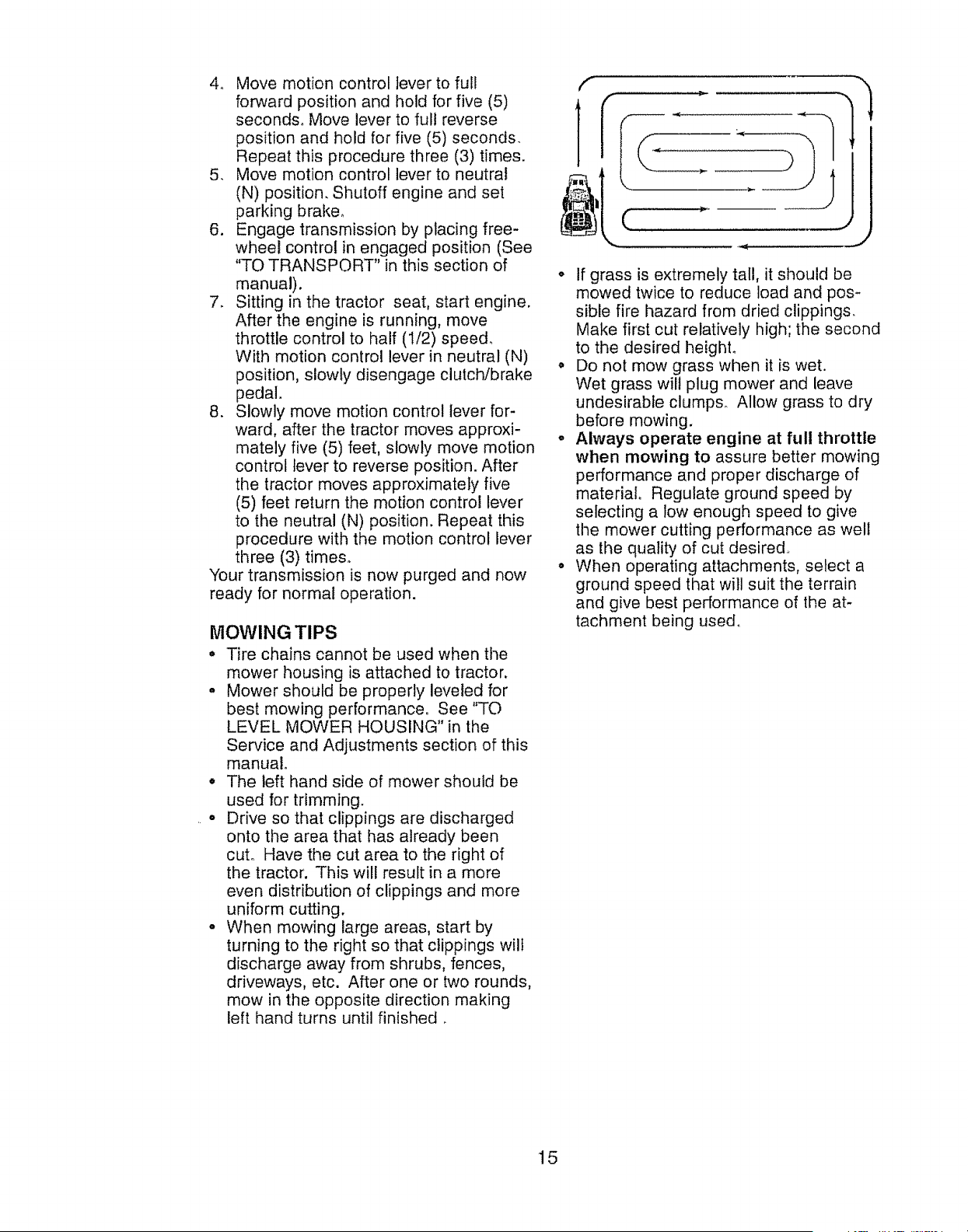
fm,,,_
• If grass is extremely tall, it should be
mowed twice to reduce load and pos-
sible fire hazard from dried clippings.
Make first cut relatively high; the second
to the desired heighL
o Do not mow grass when it is wet.
Wet grass wilt plug mower and leave
undesirable clumps. Allow grass to dry
before mowing.
° Always operate engine at full throttle
when mowing to assure better mowing
performance and proper discharge of
material° Regulate ground speed by
selecting a low enough speed to give
the mower cutting performance as well
as the quality of cut desired.
o When operating attachments, select a
ground speed that will suit the terrain
and give best performance of the at-
tachment being used,
15
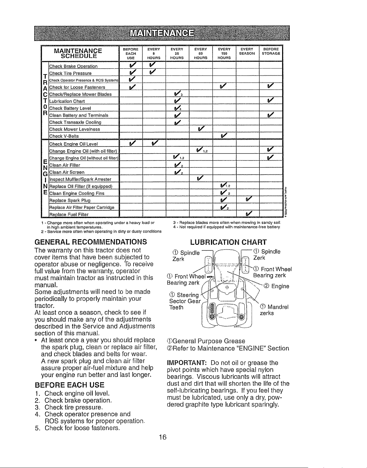
MAINTENANCE .... _FO_ _RY EV_ EVerY _VER_ EVERY _FOR_
_Ac. B 2s _o lop sEAsoN STORAGE
SCHEDULE use HOUr_S HOURS HOURS .OURS
J v"
...._ ' , .
Dheck Brake Operation
m3heck Tire Pressure ...............................
a_-.ook Opor,e_or PtesencB & ROS £yslsrn_
A _h,o,,Q,LoesoFo.,e.o,oV:.....ii'jl__...................'ii.... V' ' " V"
C ChecldReplace Mower Blades ...................................._= .....
TLubrication Chart _ I_
_ !$heck Batter,] Level ,, .
,Dlean B_:ttery and Terminals ...... _ _ ......
Dheck Transaxle Cooting ...... t_ ....
Dheck Mower Levelness .........................................................._#'
?,hoe,v.Bo,, V'
Dheck Eng|ne OII Level
,3hang° Engine O!l (with oil filler) ....................................
EiDhange Engine Otl (without oil tltte_ ............................................._J#'l,2
Ni;teenAir_,ler ............ V"_. .................
G! Clean Air Screen &_ e,'
I !,,n,,spectMufller/Spark Arrester ........
:N Replace Oil Filter (I! equipped) t_._
E',_lean Engine Cooling Fins - " V'2
Rep_a_oSpa,kPtog " _ " _ i....
,_o_,oce,,,r_,,to,_apo,Oor,,,,oe ...........................iiiilriiii _ ....................................................
Replace Fuel Filter V'
1 - Change mere olten when operaling under a heavy load or
in high ambient temperatures.,
2 _ Service more often when operaling in d#ty or dus_.y condi_ton_
3-Replace blades more ellen when mowing In sandy soil
4 - Not requbed if equipped with maintenance4ree balfery
GENERAL RECOMMENDATIONS
The warranty on this tractor does not
cover items that have been subjected to
operator abuse or negligence. To receive
full value from the warranty, operator
must maintain tractor as instructed in this
manual.
Some adjustments wil! need to be made
periodically to properly maintain your
tractor.
At least once a season, check to see if
you should make any of the adjustments
described in the Service and Adjustments
section of this manual°
• At least once a year you should replace
the spark plug, clean or replace air filter,
and check blades and belts for wean
A new spark plug and clean air filter
assure proper air-fuel mixture and help
your engine run better and test longer.
BEFORE EACH USE
1. Check engine oil level.
2. Check brake operation.
3_ Check tire pressure.
4. Check operator presence and
ROS systems for proper operation,
5. Check for loose fasteners.
LUBRICATION CHART
_.1_Spindle Spindle
Zerk Zerk
d._)Front
Bearing zerk
_.PSteer!no
Sector Gear
Teeth
Front Wheel
Bearing zerk
@ Engine
Q Mandrel
zerks
(!hGeneral Purpose Grease
@,Refer to Maintenance "ENGINE" Section
IMPORTANT: Do not oil or grease the
pivot points which have special nylon
bearings. Viscous lubricants will attract
dust and dirt that will shorten the fife of the
self-lubricating bearings. If you feel they
must be lubricated, use only a dry, pow-
dered graphite type lubricant sparingly.
16
"TRACTOR
Always observe safety rules when per-
forming any maintenance.
BRAKE OPERATION
if tractor requires more than five (5) feet to
stop at highest speed in highest gear on a
level, dry concrete or paved surface, then
brake must be serviced° (See "TO CHECK
BRAKE" in the Service and Adjustments
section of this manuat)_
TIRES
o Maintain proper air pressure in all tires
(See PSI on tires).
• Keep tires free of gasoline, oil, or insect
control chemicals which can harm rubber_
oAvoid stumps, stones, deep ruts, sharp
objects and other hazards that may
cause tire damage.
NOTE: To seal tire punctures and prevent
flat fires due to slow leaks, tire sealant
may be purchased from your local parts
dealer. Tire sealant also prevents tire dry
rot and corrosion°
OPERATOR PRESENCE SYSTEM AND
REVERSE OPERATION SYSTEM (ROS)
Be sure operator presence and reverse
operation systems are working properly_ If
your tractor does not function as de-
scribed, repair the problem immediately°
o The engine should not start unless the
brake pedal is fully depressed, and the
attachment clutch control is in the disen-
gaged position.
CHECK OPERATOR PRESENCE
SYSTEM
•When the engine is running, any at-
tempt by the operator to leave the seat
without first setting the parking brake
should shut off the engine_
o When the engine is running and the
attachment clutch is engaged, any at-
tempt by the operator to leave the seat
should shut off the engine.
° The attachment clutch should never op-
erate unless the operator is in the seat.
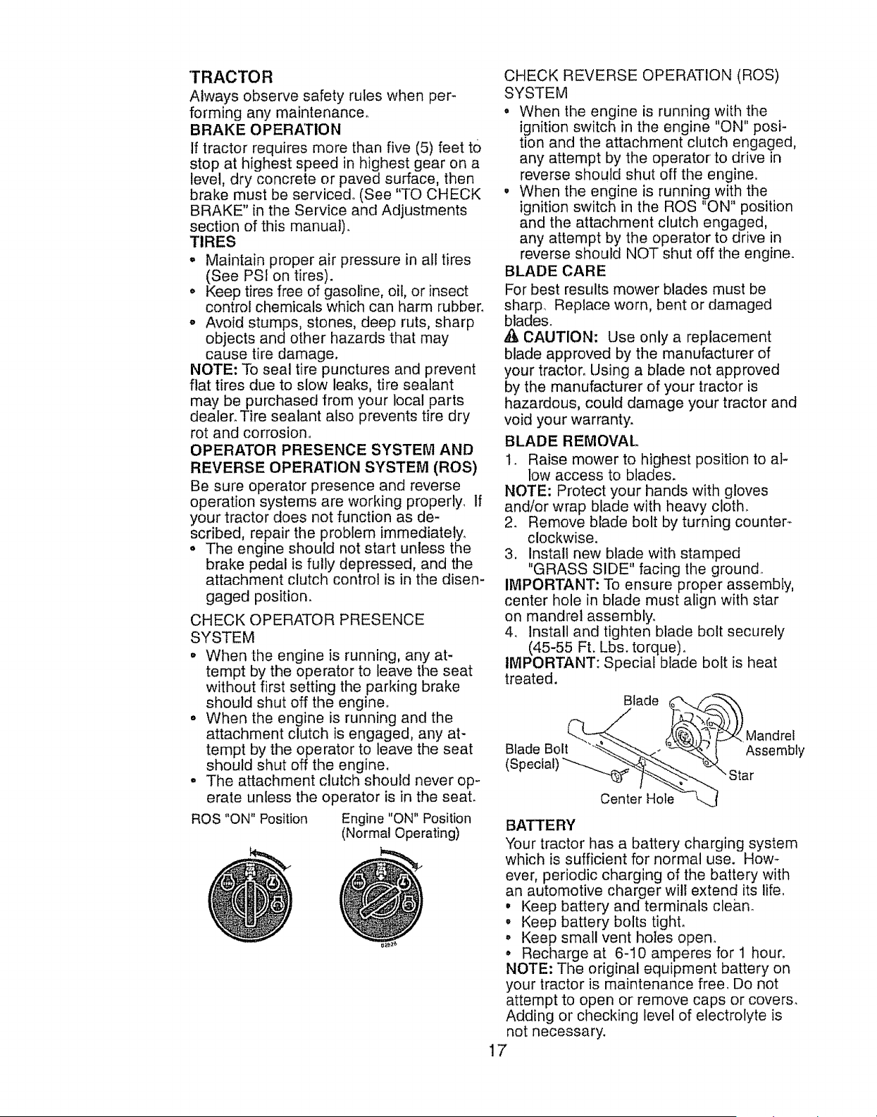
ROS "ON" Position Engine "ON" Position
(Normal Operating)
CHECK REVERSE OPERATION (ROS)
SYSTEM
•When the engine is running with the
ignition switch in the engine "ON" posi-
tion and the attachment clutcI_ engaged,
any attempt by the operator to drive in
reverse should shut off the engine,
•When the engine is running with the
ignition switch in the ROS "ON" position
and the attachment clutch engaged,
any attempt by the operator to drive in
reverse should NOT shut off the engine.
BLADE CARE
For best results mower blades must be
sharp. Replace worn, bent or damaged
blades.
,& CAUTION: Use only a replacement
blade approved by the manufacturer of
your tractor. Using a blade not approved
by the manufacturer of your tractor is
hazardous, could damage your tractor and
void your warranty.
BLADE REMOVAL
1. Raise mower to highest position to al-
low access to blades.
NOTE: Protect your hands with gloves
and/or wrap blade with heavy cloth.
2. Remove blade bolt by turning ceunter_
clockwise.
3. install new blade with stamped
"GRASS SIDE" facing the ground,.
IMPORTANT: To ensure proper assembly,
center hole in blade must align with star
on mandrel assembly°
4o Install and tighten blade bolt securely
(45-55 Ft. Lbs, torque).
IMPORTANT: Special blade bolt is heat
treated,
Blade _ f.__._\
Blade Bolt "_--_"'_""--_" '_'1 Assembly
(SPecial) "_'_"_%_ Star
Center Hole t...j
BATTERY
"four tractor has a battery charging system
which is sufficient for normal use. How-
ever, periodic charging of the battery with
an automotive charger wilt extend its life,
° Keep battery and terminals clean.
•Keep battery bolts tight.
° Keep small vent holes open°
° Recharge at 6-10 amperes for 1 hour.
NOTE: The original equipment battery on
your tractor is maintenance free, Do not
attempt to open or remove caps or covers.
Adding or checking level of electrolyte is
not necessary.
17
TO CLEANBATTERYANDTERMINALS
Corrosionanddirton thebatteryandtermi-
nalscancausethebatteryto "leak"power,
1, DisconnectBLACKbatterycablefirst
then RED batterycableand remove
batteryfromtractor.
2o Rinsethe batterywith plainwater and
dry.
3, Cleanterminalsandbatterycableends
with wire brushuntilbright.
4_,Coatterminalswith greaseor petro-
leumjelly.
5. Reinstallbattery(See"REPLACING
BATTERY"in theSERVICEANDAD-
JUSTMENTSsectionof this manual)°
TRANSAXLECOOLING
The transmissionfan andcoolingfins
should be keptcleanto assureproper
cooling°
Do not attemptto cleanfanor transmis-
sionwhile engineis runningor while the
transmissionishot°Topreventpossible
damageto seals,do not usehighpressure
water or steamto cleantransaxle,_
,, Inspectcoolingfan to be surefan blades
are intactandclean.
,, Inspectcoolingfins for dirt, grassclip-
pingsand othermaterials°Toprevent
damageto seals,do not usecom-
pressedair or highpressuresprayerto
cleancoolingfins,
TRANSAXLE PUMP FLUID
Thetransaxlewas sealedatthe factory
and fluid maintenanceis not requiredfor
the lifeof the transaxle,Shouldthe trans-
axfeeverleakor requireservicing,contact
your nearestqualifiedservicecenter°
V-BEI.TS
CheckV-beltsfor deteriorationand wear
after 100hoursof operationand replace
if necessary.Thebelts are notadjustable_
Replacebeltsif theybeginto slipfrom
wear.
ENGINE
LUBRICATION
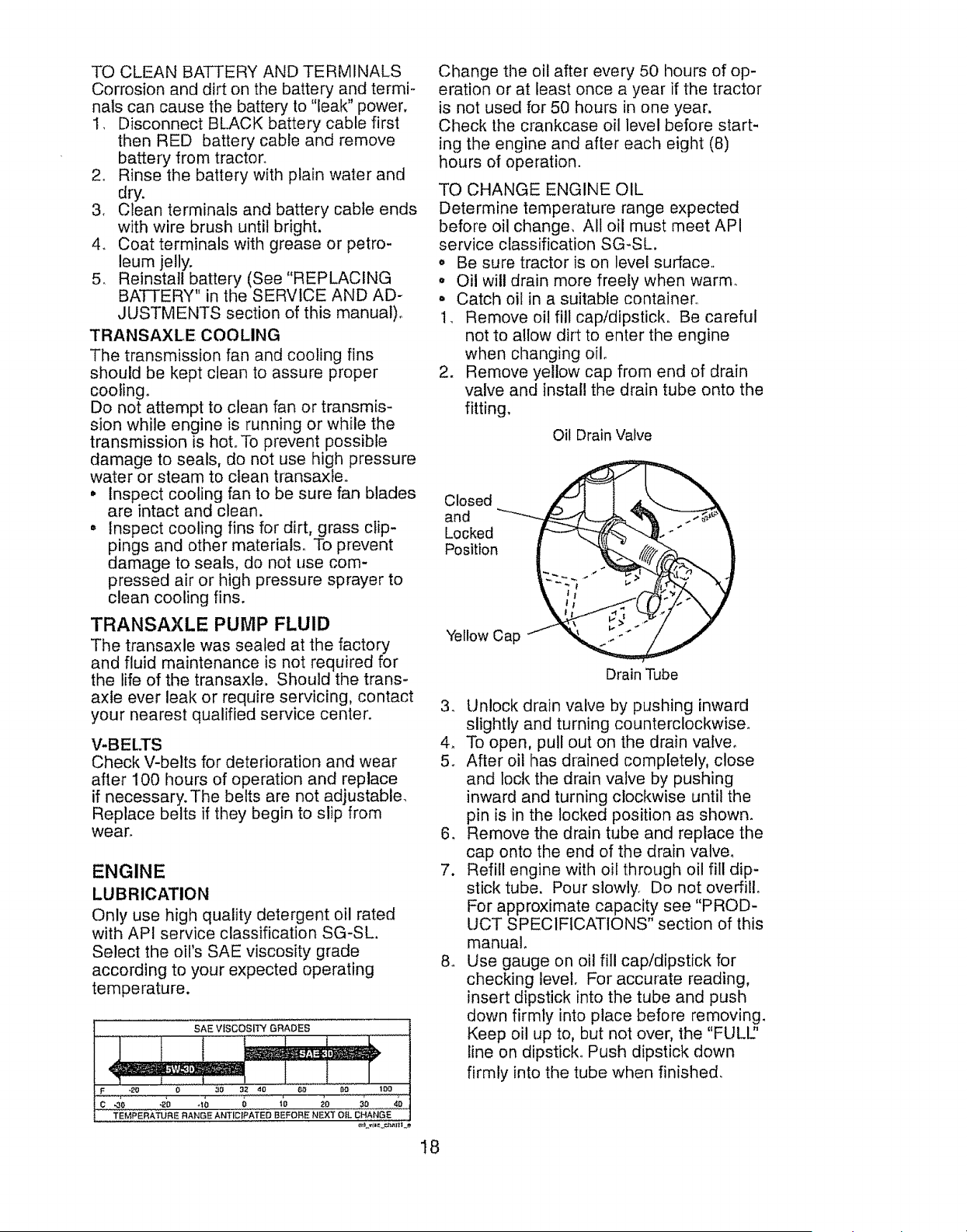
Only use high quality detergent oil rated
with API service classification SG-SL,
Select the oil's SAE viscosity grade
according to your expected operating
temperature.
SAE VISCOSITY GRADES
F _,o o 3o _2 do ......'_'o'....... oo loo
"I'EM,PERt,,TURE RANGE ANTIDIPATED BEFORE NEXT OIL I_HAN_E
Change tile oil after every 50 hours of op-
eration or at least once a year if the tractor
is not used for 50 hours in one year.
Check the crankcase oil level before start-
ing the engine and after each eight (8)
hours of operation.
TO CHANGE ENGINE OIL
Determine temperature range expected
before oil change, All oil must meet API
service classification SG-SL.
,, Be sure tractor is on level surface.
• Oil will drain more freely when warm.
. Catch oil in a suitable container,
1, Remove oil fill cap/dipstick. Be careful
not to allow dirt to enter the engine
when changing oil°
2. Remove yellow cap from end of drain
valve and install the drain tube onto the
fitting.
Oil Drain Valve
Closed
and
Locked
Position
Yellow Cap
Drain Tube
3. Unlock drain valve by pushing inward
slightly and turning counterclockwise°
4. To open, pull out on the drain valve°
5. After oil has drained completely, close
and lock the drain valve by pushing
inward and turning clockwise until the
pin is in the locked position as shown.
6, Remove the drain tube and replace the
cap onto the end of the drain valve.
7. Refill engine with oil through oil fill dip-
stick tube, Pour slowly. Do not overfill,
For approximate capacity see "PROD-
UCT SPECIFICATIONS" section of this
manual.
8. Use gauge on oil fill cap/dipstick for
checking level. For accurate reading,
insert dipstick into the tube and push
down firmly into place before removing.
Keep oil up to, but not over, the "FULl2
line on dipstick Push dipstick down
firmly into the tube when finished.
I8
ENGINE OIL FILTER
Replace the engine oil filter every season
or every other oil change if the tractor is
used more than 100 hours in one year_
AIR FILTER
Your engine will not run properly using a
dirty air filter.
Service air cleaner more often under
dusty conditions, See Engine Manual.
CLEAN AIR SCREEN
Air screen must be kept free of dirt and
chaff to prevent engine damage from
overheating. Clean with a wire brush or
compressed air to remove dirt and stub-
born dried gum fibers_
MUFFLER
inspect and replace corroded muffler and
spark arrester (if equipped) as it could cre-
ate a fire hazard and/or damage.
SPARK PLUG(S)
Replace spark plug(s) at the beginning
of each mowing season or after every
100 hours of operation, whichever occurs
first. Spark plug type and gap setting are
shown in "PRODUCT SPECIFICATIONS"
section of this manual
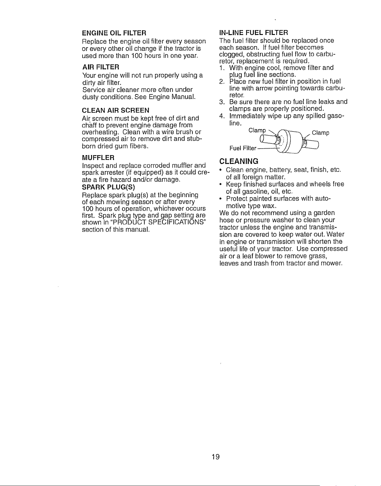
IN-LINE FUEL FILTER
The fuel filter should be replaced once
each season. If fuel filter becomes
clogged, obstructing fuel flow to carbu-
retor, replacement is required.
to With engine cool, remove filter and
plug fuel line sections.
2. Place new fuel filter in position in fuel
line with arrow pointing towards carbu-
retor.
3. Be sure there are no fuel line leaks and
clamps are properly positioned.
4., Immediately wipe up any spilled gaso-
line.
Ctam__amp
Fuel Filter -_._/
CLEANING
o Ctean engine, battery, seat, finish, etc.
of all foreign matter,
o Keep finished surfaces and wheels free
of all gasoline, oil, etc.
° Protect painted surfaces with auto-
motive type wax°
We do not recommend using a garden
hose or pressure washer to clean your
tractor unless tile engine and transmis-
sion are covered to keep water ouL Water
in engine or transmission will shorten the
useful life of your tractor° Use compressed
air or a leaf blower to remove grass,
leaves and trash from tractor and mower.
19
WARNING: TO AVOID SERIOUS INJURY, BEFORE PERFORMING ANY SER-VICE OR ADJUSTMENTS:
1, Depress brake pedal fully and set parking brake°
2o Place attachment clutch in "DISENGAGED" position,
3o Turn ignition key to "STOP" and remove key,
4. Make sure the blades and all moving parts have completely stopped°
5. Disconnect spark plug wire from spark plug and place wire where it cannot
come in contact with plug.
TRACTOR
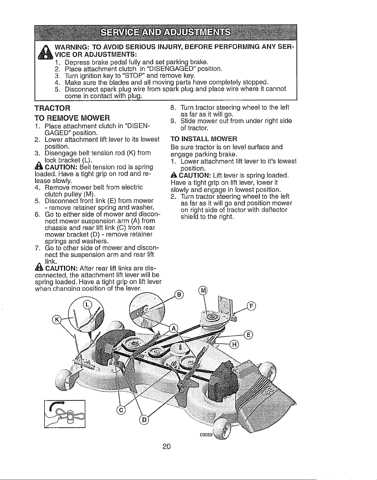
TO REMOVE MOWER
1, Place attachment clutch in "DISEN-
GAGED" position.
2. Lower attachment lift lever to its lowest
position_
3. Disengage belt tension rod (K) from
lock bracket (L).
_tb CAUTION: Belt tension rod is spring
loaded. Have a tight grip on rod and re-
lease slowly,
4. Remove mower belt from electric
clutch pulley (M).
5. Disconnect front link (E) from mower
* remove retainer spring and washer.
6. Go to either side of mower and discon-
nect mower suspension arm (A) from
chassis and rear lift link (C) from rear
mower bracket (D) - remove retainer
springs and washers.
7. Go to other side of mower and discon-
nect the suspension arm and rear lift
link.
,_ CAUTION: After rear lift links are dis-
connected, the attachment lift lever will be
spring loaded. Have a tight grip on lift lever
when chanaino Position of the lever._
8o Turn tractor steering wheel to the left
as far as it will go,
9. Slide mower out from under right side
of tractor,
TO INSTALL MOWER
Be sure tractor is on level surface and
engage parking brake.
1. Lower attachment lift lever to it's lowest
_ position.
CAUTION: Lift lever is spring loaded.
Have a tight grip on lift lever, lower it
slowly and engage in lowest position.
2, Turn tractor steering wheel to the left
as far as it will go and position mower
on right side of tractor with deflector
shield to the right.
20
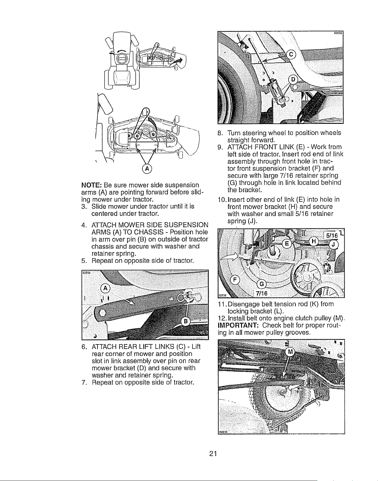
NOTE: Be sure mower side suspension
arms (A) are pointing forward before slid-
ing mower under tractor.
3. Slide mower under tractor until it is
centered under tractor,
4, ATTACH MOWER SIDE SUSPENSION
ARMS (A) TO CHASSIS - Position hole
in arm over pin (B) on outside of tractor
chassis and secure with washer and
retainer spring.
5, Repeat on opposite side of tractor.
8_
9_
10.
Turn steering wheel to position wheels
straight forward
ATTACH FRONT LINK (E) - Work from
left side of tractor. Insert rod end of link
assembly through front hole in trac-
tor front suspension bracket (F) and
secure with large 7/16 retainer spring
(G) through hole in link located behind
the bracket.
Insert other end of link (E) into hole in
front mower bracket (H) and secure
with washer and small 5/16 retainer
spring (J),
6. ATTACH REAR LIFT LINKS (C) - Lift
rear corner of mower and position
slot in link assembly over pin on rear
mower bracket (D) and secure with
washer and retainer spring.
7, Repeat on opposite side of tractor,
11, Disengage belt tension rod (K) from
locking bracket (L),
12. Install belt onto engine clutch pulley (M)o
IMPORTANT- Check belt for proper rout-
ing in all mower pulley grooves°
21
13. Engage belt tension rod (K) on locking
bracket (L).
,& CAUTION: Belt tension rod is spring
loaded. Have a tight grip on rod and en-
gage slowly.
14. Raise attachment lift lever to highest
position.
15. If necessary, adjust gauge wheels be..
fore operating mower as shown in the
Operation section of this manual.
TO LEVEL MOWER
Make sure tires are properly inflated to
the PS! shown on tires. If tires are over
or under inflated, it may affect the appear-
ance of your lawn and lead you to think
the mower is not adjusted properly.
VISUAL SIDE-TO-SIDE ADJUSTMENT
1. With all tires properly inflated and if
your lawn appears unevenly cut, de-
termine which side of mower is cutting
lower.
NOTE: As desired, you can raise the low
side of mower or lower the high side°
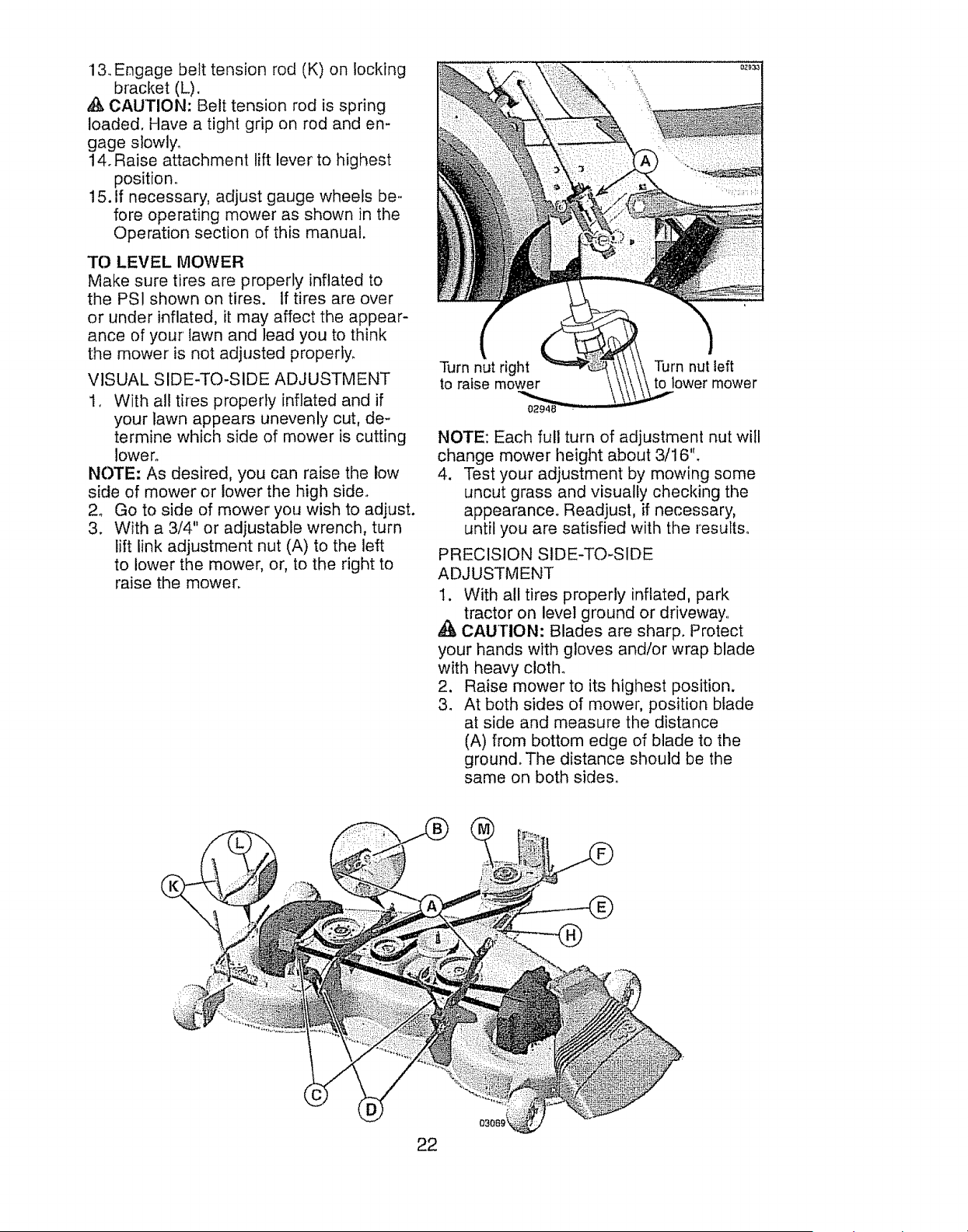
2o Go to side of mower you wish to adjust.
3. With a 3/4" or adjustable wrench, turn
lift link adjustment nut (A) to the left
to lower the mower, or, to the right to
raise the mower.
Turn nut right
to raise mower
Turn nut left
to lower mower
NOTE: Each full turn of adjustment nut will
change mower height about 3116".
4. Test your adjustment by mowing some
uncut grass and visually checking the
appearance° Readjust, if necessary,
until you are satisfied with the results_
PRECISION SIDE-TO-SIDE
ADJUSTMENT
I. With all tires properly inflated, park
tractor on level ground or driveway
CAUTION: Blades are sharp. Protect
your hands with gloves and/or wrap blade
with heavy cloth°
2. Raise mower to its highest position.
3. At both sides of mower, position blade
at side and measure the distance
(A) from bottom edge of blade to the
ground. The distance should be the
same on both sides.
22
i A
4o tf adjustment is necessary, see steps 2
and 3 in Visual Adjustment instructions
above,
5. Recheck measurements, adjust if nec-
essary until both sides are equal.
FRONT-TO-BACK ADJUSTMENT
IMPORTANT: Deck must be level side-
to-side.
To obtain the best cutting results, the
mower blades should be adjusted so the
front tip is 1/8" to 1/2" lower than the rear
tip when the mower is in its highest posi-
tion.
_, CAUTION: Blades are sharp. Protect
your hands with gloves and/or wrap blade
with heavy cloth.
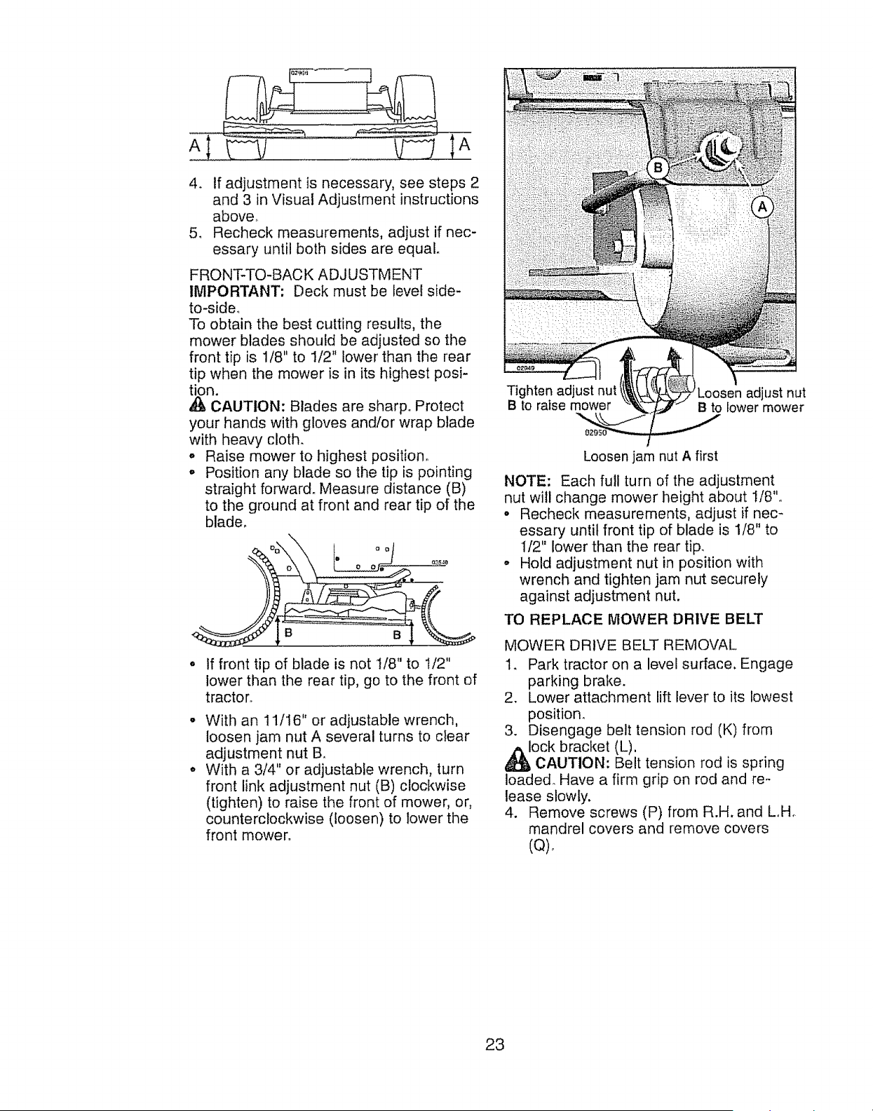
o Raise mower to highest position°
o Position any blade so the tip is pointing
straight forward° Measure distance (B)
to the ground at front and rear tip of the
blade.
B B
If front tip of blade is not 118" to 1/2"
lower than the rear tip, go to the front of
tractor.
With an 11/16" or adjustable wrench,
loosen jam nut A several turns to clear
adjustment nut B,.
With a 3/4" or adjustable wrench, turn
front link adjustment nut (B) clockwise
(tighten) to raise the front of mower, or,
counterclockwise (loosen) to lower the
front mower.
Tighten adjust nut
B to raise mower Loosen adjust nut
B to lower mower
Loosen jam nut A first
NOTE: Each full turn of the adjustment
nut will change mower height about 1/8".
• Recheck measurements, adjust if nec_
essary until front tip of blade is 1/8" to
1/2" lower than the rear tip.
° Hold adjustment nut in position with
wrench and tighten jam nut securely
against adjustment nut.
TO REPLACE MOWER DRIVE BELT
MOWER DRIVE BELT REMOVAL
1. Park tractor on a level surface. Engage
parking brake.
2. Lower attachment lift lever to its lowest
position.
3. Disengage belt tension rod (K) from
ock bracket (L),
CAUTION: Belt tension rod is spring
loaded. Have a firm grip on rod and re-
lease slowly.
4. Remove screws (P) from R.H. and LoHo
mandrel covers and remove covers
(Q),
23
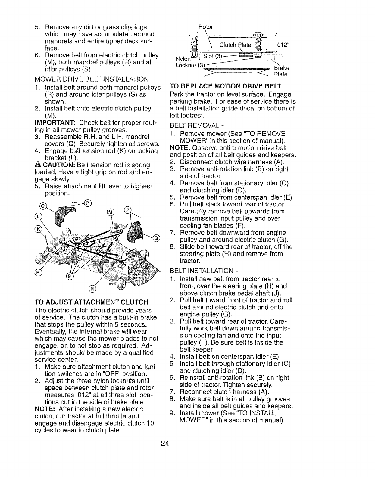
5o Remove any dirt or grass clippings
which may have accumulated around
mandrels and entire upper deck sur-
face.
6. Remove belt from electric clutch pulley
(M), both mandrel pulleys (R) and all
idler pulleys (S)_
MOWER DRIVE BELT INSTALLATION
1_ Install belt around both mandrel pulleys
(R) and around idler pulleys (S) as
shown.
2. Install belt onto electric clutch pulley
(M).
IMPORTANT: Check belt for proper rout-
ing in all mower pulley grooves.
3. Reassemble R.H. and LoHo mandrel
covers (Q). Securely tighten all screws.
4. Engage belt tension rod (K) on locking
bracket (L)
,_ CAUTION: Belt tension rod is spring
loaded. Have a tight grip on rod and en-
gage slowly.
5. Raise attachment lift lever to highest
position.
®
TO ADJUST ATTACHMENT CLUTCH
The electric clutch should provide years
of service. The clutch has a built-in brake
that stops the pulley within 5 seconds.
Eventually, the internal brake will wear
which may cause the mower blades to not
engage, or, to not stop as required. Ad-
justments should be made by a qualified
service center.
1. Make sure attachment clutch and igni-
tion switches are in "OFF" position.
2, Adjust the three nylon locknuts until
space between clutch plate and rotor
measures ,012" at all three slot loca-
tions cut in the side of brake plate_
NOTE: After installing a new electric
clutch, run tractor at full throttle and
engage and disengage electric clutch 10
cycles to wear in clutch plate,,
Rotor
[\\ Clutch Plate _ I _012"
Nylon_'-_[ blo ! )
Cooknut I__ ake
_ Plate
TO REPLACE MOTION DRIVE BELT
Park the tractor on level surface. Engage
parking brake, For ease of service there is
a belt installation guide decal on bottom of
left footrest.
BELT REMOVAL -
14 Remove mower (See "TO REMOVE
MOWER" in this section of manual).,
NOTE: Observe entire motion drive belt
and position of all belt guides and keepers.
2. Disconnect clutch wire harness (A)_
3. Remove anti-rotation link (B) on right
side of tractor°
4o Remove belt from stationary idler (C)
and clutching idler (D).,
5. Remove belt from centerspan idler (E).
6. Pull belt slack toward rear of tractor.
Carefully remove belt upwards from
transmission input pulley and over
cooling fan blades (F).
7. Remove belt downward from engine
pulley and around electric clutch (G).
8. Slide belt toward rear of tractor, off the
steering plate (H) and remove from
tractor.
BELT INSTALLATION -
1. Install new belt from tractor rear to
front, over the steering plate (H) and
above clutch brake pedal shaft (J)o
2. Pull belt toward front of tractor and roll
belt around electric clutch and onto
engine pulley (G).
3. Pull belt toward rear of tractor. Care-
fully work belt down around transmis-
sion cooling fan and onto the input
pulley (F). Be sure belt is inside the
belt keeper.
4. Install belt on centerspan idler (E)o
5. install belt through stationary idler (C)
and clutching idler (D),
6. Reinstall anti-rotation link (B) on right
side of tractor. Tighten securely_
7. Reconnect clutch harness (A).
8. Make sure belt is in all pulley grooves
and inside all belt guides and keepers.
9. Install mower (See "TO INSTALL
MOWER" in this section of manual).
24
__-@
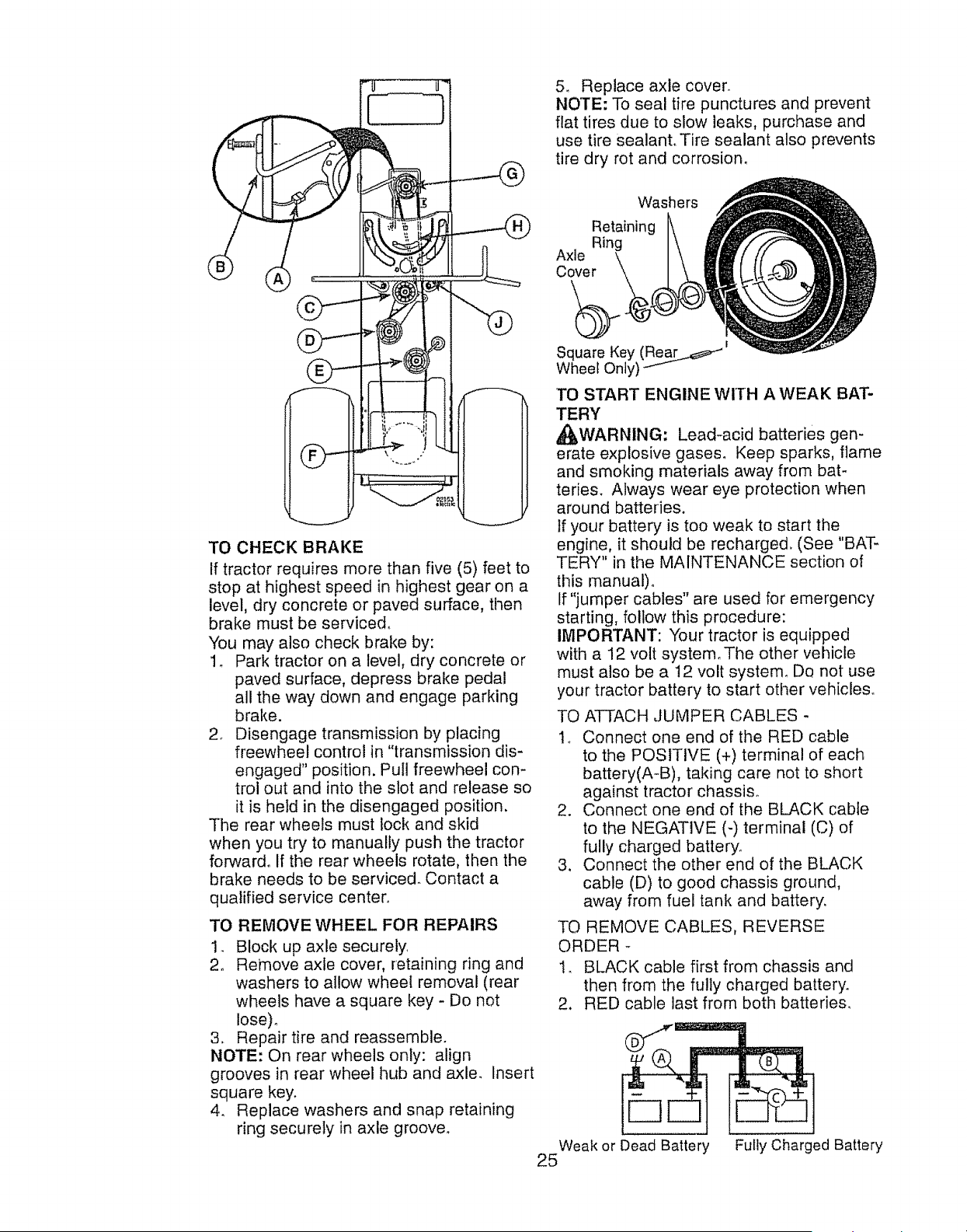
TO CHECK BRAKE
if tractor requires more than five (5) feet to
stop at highest speed in highest gear on a
level, dry concrete or paved surface, then
brake must be serviced.
You may also check brake by:
1. Park tractor on a level, dry concrete or
paved surface, depress brake pedal
all the way down and engage parking
brake.
2_ Disengage transmission by placing
freewheel control in "transmission dis-
engaged" position. Pull freewheel con-
trol out and into the slot and release so
it is held in the disengaged position.
The rear wheels must lock and skid
when you try to manually push the tractor
forward° If the rear wheels rotate, then the
brake needs to be serviced. Contact a
qualified service center°
TO REMOVE WHEEL FOR REPAIRS
1. Block up axle securely.
2. Remove axle cover, retaining ring and
washers to allow wheel removal (rear
wheels have a square key - Do not
Iose)_
3_ Repair tire and reassemble.
NOTE: On rear wheels only: align
grooves in rear wheel hub and axle. Insert
square key.
4. Replace washers and snap retaining
ring securely in axle groove°
5. Replace axle cover.
NOTE: To seal tire punctures and prevent
flat tires due to slow leaks, purchase and
use tire sealant. Tire sealant also prevents
tire dry rot and corrosion.
Washers
Retaining
Ring
Axle
Cover
|
Square Key (Rear_
Wheel Only)
TO START ENGINE WITH A WEAK BAT-
TERY
,__WARNING: Lead-acid batteries gen-
erate explosive gases. Keep sparks, flame
and smoking materials away from bat-
teries. Always wear eye protection when
around batteries°
tf your battery is too weak to start the
engine, it should be recharged. (See "BAT-
TERY" in the MAINTENANCE section of
this manual)°
If "jumper cables" are used for emergency
starting, follow this procedure:
IMPORTANT: Your tractor is equipped
with a 12 volt system_The other vehicle
must also be a 12 volt system. Do not use
your tractor battery to start otl_er vehicles°
TO ATTACH JUMPER CABLES -
1. Connect one end of the RED cable
to the POSITIVE (+) terminal of each
battery(A-B), taking care not to short
against tractor chassis.
2. Connect one end of the BLACK cable
to the NEGATIVE (-) terminal (C) of
fully charged battery.
3. Connect the other end of the BLACK
cable (D) to good chassis ground,
away from fuel tank and battery_
TO REMOVE CABLES, REVERSE
ORDER -
I_ BLACK cable first from chassis and
then from the fully charged battery.
2. RED cable last from both batteries.
Weak or Dead Battery Fully Charged Battery
25
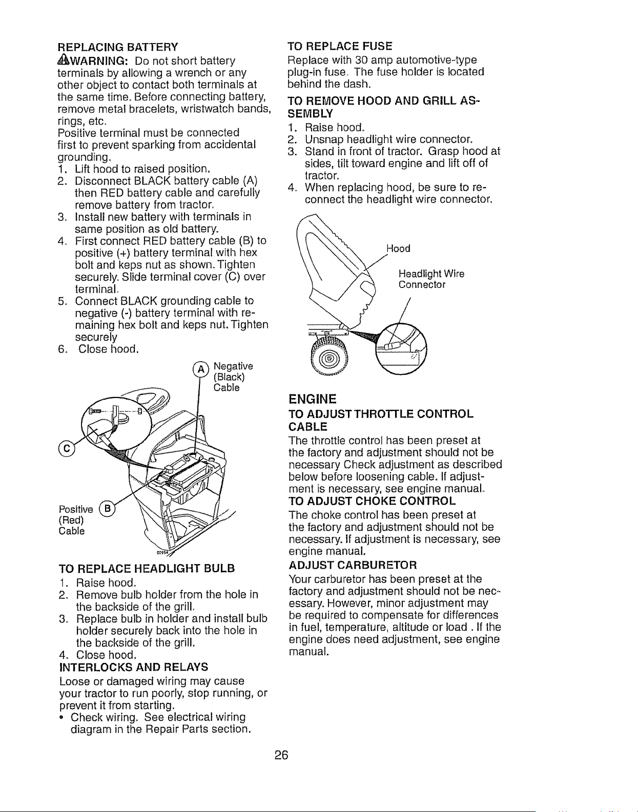
REPLACINGBATTERY
d_,WARNING:Do notshortbattery
terminalsby allowingawrenchor any
otherobjectto contactbothterminalsat
timesametime.Beforeconnectingbattery,
removemetalbracelets,wristwatchbands,
rings,etc.
Positiveterminalmustbe connected
first to preventsparkingfrom accidental
grounding.
1, Lift hoodto raisedposition.
2. DisconnectBLACKbatterycable(A)
then REDbatterycableand carefully
removebatteryfromtractor.
3, Installnewbatterywith terminalsin
samepositionas old battery.
4, FirstconnectRED batterycable(B)to
positive(+)batteryterminalwith hex
bolt and kepsnutas shown_Tighten
securely.Slideterminalcover(C)over
terminal_
5o ConnectBLACKgroundingcableto
negative(-) batteryterminalwith re-
maininghex boltand kepsnut.Tighten
securely
6. Closehood.
_ Negative
(Black)
Cable
p,"
Positive
(Red)
Cable
TO REPLACE HEADLIGHT BULB
1. Raise hood°
2. Remove bulb holder from the hole in
the backside of the grill.
3. Replace bulb in holder and install bulb
holder securely back into the hole in
the backside of the grill.
4. Close hood.
INTERLOCKS AND RELAYS
Loose or damaged wiring may cause
your tractor to run poorly, stop running, or
prevent it from starting,
• Check wiring. See electrical wiring
diagram in the Repair Parts section.
TO REPLACE FUSE
Replace with 30 amp automotive-type
plug-in fuse. The fuse holder is located
behind the dash.
TO REMOVE HOOD AND GRILL AS-
SEMBLY
1. Raise hood°
2. Unsnap headlight wire connector.
3. Stand in front of tractor. Grasp hood at
sides, tilt toward engine and lift off of
tractor.
4_ When replacing hood, be sure to re-
connect the headlight wire connector.
Hood
Headlight Wire
Connector
ENGINE
TO ADJUST THROTTLE CONTROL
CABLE
The throttle control has been preset at
the factory and adjustment should not be
necessary Check adjustment as described
below before loosening cable. If adjust-
ment is necessary, see engine manual.
TO ADJUST CHOKE CONTROL
The choke control has been preset at
the factory and adjustment should not be
necessary. If adjustment is necessary, see
engine manual.
ADJUST CARBURETOR
Your carburetor has been preset at the
factory and adjustment should not be nec-
essary. However, minor adjustment may
be required to compensate for differences
in fuel, temperature, altitude or toad _ If the
engine does need adjustment, see engine
manual.
26
Immediately prepare your tractor for stor-
age at the end of the season or if the trac-
0l_will not be used for 30 days or more.
WARNING: Never store the tractor
with gasoline in the tank inside a building
where fumes may reach an open flame
or spark. Allow the engine to cool before
storing in any enclosure.
TRACTOR
When tractor is to be stored for a period
of time, ciean it thoroughly, remove all dirt,
grease, leaves, etc. Store in a clean, dry
area.
1. Clean entire tractor (See "CLEANING"
in the Maintenance section of this
manual).
2, Inspect and replace belts, if necessary
(See belt replacement instrudtions in
the Service and Adjustments section of
this manual).
3. Lubricate as shown in the Maintenance
section of this manual.
4. Be sure that all nuts, bolts and screws
are securely fastened.. Inspect moving
parts for damage, breakage and wear°
Replace if necessary.
5. Touch up all rusted or chipped paint
surfaces; sand lightly before painting.
BATTERY
• Fully charge the battery for storage_
o After a period of time in storage, battery
may require recharging.
• To help prevent corrosion and power
bakage during long periods of storage,
battery cables should be disconnected
and battery cleaned thoroughly (see '"1O
CLEAN BATTERY AND TERMINALS" in
the Maintenance section of this manual).
o After cleaning, leave cables discon-
nected and place cables where they
cannot come in contact with battery
terminals.
• If battery is removed from tractor for
storage, do not store battery directly on
concrete or damp surfaces.
ENGINE
FUEL SYSTEM
IMPORTANT: It is important to prevent
gum deposits from forming in essential
fuel system parts such as carburetor, fuel
hose, or tank during storage. Also, alcohol
blended fuels (called gasohol or using
ethanol or methanol) can attract moisture
which leads to separation and formation of
acids during storage_ Acidic gas can dam-
age the fuel system of an engine while in
storage.
° Empty the fuel tank by starting the en-
gine and letting it run until the fuel lines
and carburetor are empty.
• Never use engine or carburetor cleaner
products in the fuel tank or permanent
damage may occur°
o Use fresh fuel next season.
NOTE: Fuel stabilizer is an acceptable
alternative in minimizing the formation of
fuel gum deposits during storage. Add
stabilizer to gasoline in fuel tank or stor_
age container. Always follow the mix ratio
found on stabilizer container. Run engine
at least 10 minutes after adding stabilizer
to allow the stabilizer to reach the carbure-
tor. Do not empty the gas tank and carbu-
retor if using fuel stabilizer.
ENGINE OIL
Drain oil (with engine warm) and replace
with clean engine oil. (See "ENGINE" in
the Maintenance section of this manual).
CYLINDER(S)
1o Remove spark piug(s)o
2, Pour one ounce of oil through spark
plug hole(s) into cylinder(s),
3. Turn ignition key to start position for a
few seconds to distribute oil.
4. Replace with new spark plug(s)_
OTHER
• Do not store gasoline from one season
to another.
,, Replace your gasoline can if your can
starts to rust. Rust and/or dirt in your
gasoline will cause problems.
° If possible, store your tractor indoors
and cover it to give protection from dust
and dirt.
° Cover your tractor with a suitable pro-
tective cover that does not retain mois-
ture. Do not use plastic. Plastic cannot
breathe which allows condensation to
form and will cause your tractor to rust.
IMPORTANT: Never cover tractor while
engine and exhaust areas are still warm.
27
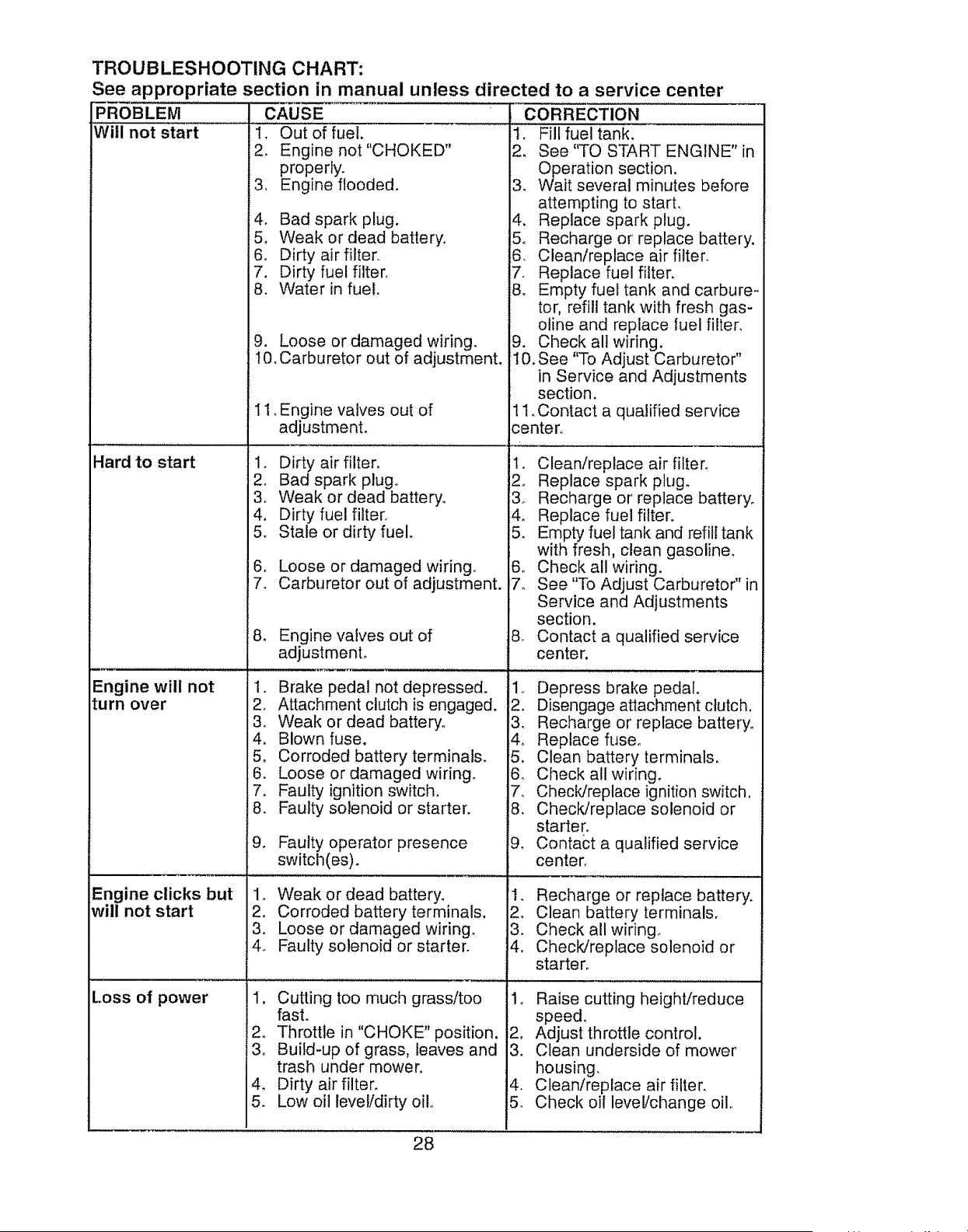
TROUBLESHOOTING CHART:
See appropriate section in manual unless directed to a service center
PROBLEM
Will not start
Hard to start
Engine will not
turn over
Engine clicks but
will not start
CAUSE
1. Out of fuel.
2. Engine not "CHOKED"
properly.
3. Engine flooded.
Loss of power
4. Bad spark plug.
5. Weak or dead battery°
6. Dirty air filter.
7. Dirty fuel filter.
8. Water in fuel.
9. Loose or damaged wiring.
t0. Carburetor out of adjustment.
11, Engine valves out of
adjustment,
1. Dirty air filter.
2_ Bad spark plugo
3_ Weak or dead battery.
4. Dirty fuel filter.
5o Stale or dirty fuel.
6_ Loose or damaged wiring.
7. Carburetor out of adjustment.
8, Engine valves out of
adjustment,
1. Brake pedal not depressed.
2. Attachment clutch is engaged.
3. Weak or dead battery.
4. Blown fuse.
5, Corroded battery terminals.
6. Loose or damaged wiring.
7. Faulty ignition switch.
8. Faulty solenoid or starter.
Faulty operator presence
switch(es).
1o Weak or dead battery.
2. Corroded battery terminals,
3. Loose or damaged wiring.
4. Faulty solenoid or starter.
1, Cutting too much grass/too
fast.
2o Throttle in "CHOKE" position,
3. Build-up of grass, leaves and
trash under mower,
. Dirty air filter.
. Low oil level/dirty clio
CORRECTION
1. Fill fuel tank.
2. See "TO START ENGINE" in
Operation section.
3. Wait several minutes before
attempting to start.
4. Replace spark plug.
5o Recharge or replace battery.
6 Clean/replace air filter.
7. Replace fuel filter.
8. Empty fuel tank and carbure-
tor, refill tank with fresh gas-
oline and replace luel filter.
9. Check all wiring.
t0. See "To Adjust Ca rbu retor"
in Service and Adjustments
section.
11. Contact a qualified service
center.
1. Clean/replace air filter.
2. Replace spark plugo
3_ Recharge or replace battery.
4. Replace fuel filter.
5. Empty fuel tank and refill tank
with fresh, clean gasoline,
6. Check all wiring.
7o See "To Adjust Carburetor" in
Service and Adjustments
section.
8, Contact a qualified service
center,
1. Depress brake pedal.
2. Disengage attachment clutch,
3. Recharge or replace battery,,
4o Replace fuse.
5. Clean battery terminals.
6. Check all wiring.
7_ Check/replace ignition switch,
8. Check/replace solenoid or
starter.
9. Contact a qualified service
center,
1. Recharge or replace battery,
2. Clean battery terminals.
3. Check all wiring_
4, ChecWreplace solenoid or
starter.
4_
5.
Raise cutting height/reduce
speed.
Adjust throttle control,
Clean underside of mower
housing.
Clean/replace air filter.
Check oil level/change oil,
28
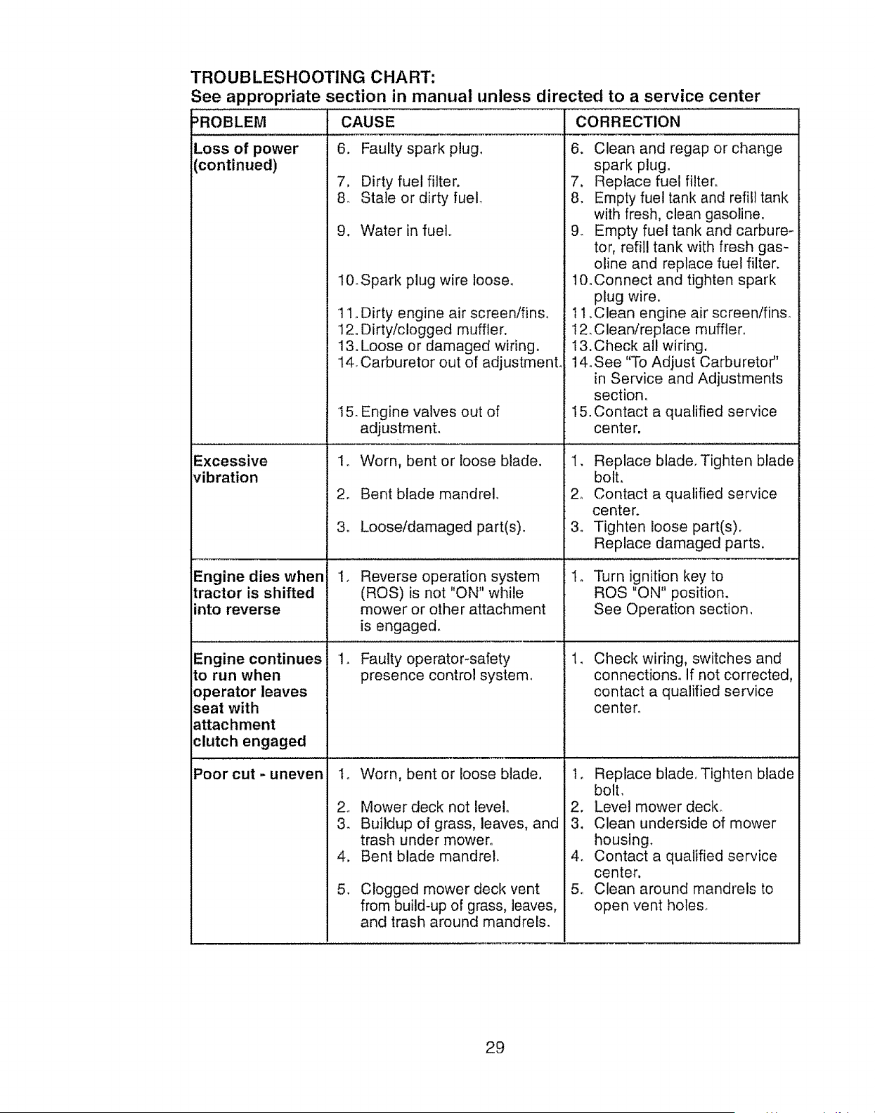
TROUBLESHOOTING CHART:
See appropriate section in manual unless directed to a service center
)ROBLEM CAUSE CORRECTION
Loss of power
continued)
Excessive
vibration
Engine dies when
tractor is shifted
into reverse
Engine continues
to run when
operator leaves
seat with
attachment
clutch engaged
Poor cut - uneven
6. Faulty spark plug,
7, Dirty fuel filter.
8. Stale or dirty fuel
9. Water in fuel.
10.Spark plug wire loose.
11, Dirty engine air screen/fins_
12. Dirty/clogged muffler.
13. Loose or damaged wiring.
14. Carburetor out of adjustment.
t 5. Engine valves out of
adjustment.
1o Worn, bent or loose blade.
2. Bent blade mandrel.
3. Looseldamaged part(s).
Reverse operation system
(ROS) is not "ON" while
mower or other attachment
is engaged.
1. Faulty operator-safety
presence control system.
2,
3.
4.
5,
Worn, bent or loose blade,
Mower deck net level,
Buildup of grass, leaves, and
trash under mower.
Bent blade mandrel.
Clogged mower deck vent
from build-up of grass, leaves,
and trash around mandrels.
6. Clean and regap or change
spark plug.
7, Replace fuel filter.
8, Empty fuel tank and refill tank
with fresh, clean gasoline.
9. Empty fuel tank and carbure-
tor, refill tank with fresh gas-
oline and replace fuel filter,
10. Connect and tighten spark
plug wire°
t 1,Clean engine air screenlfinso
12, Clean/replace muffler°
13.Check all wiring.
14. See "To Adjust Carburetor"
in Service and Adjustments
section,
i5. Contact a qualified service
center,
1, Replace blade, Tighten blade
bolt,
2, Contact a qualified service
center.
3. Tighten loose part(s),
Replace damaged parts.
Turn ignition key to
ROS "ON" position.
See Operation section,
Check wiring, switches and
connections. If not corrected,
contact a qualified service
center,
1, Replace blade,, Tighten blade
bolt,
2. Level mower deck.
3. Clean underside of mower
housing.
4. Contact a qualified service
center,
5. Clean around mandrels to
open vent holes.
29
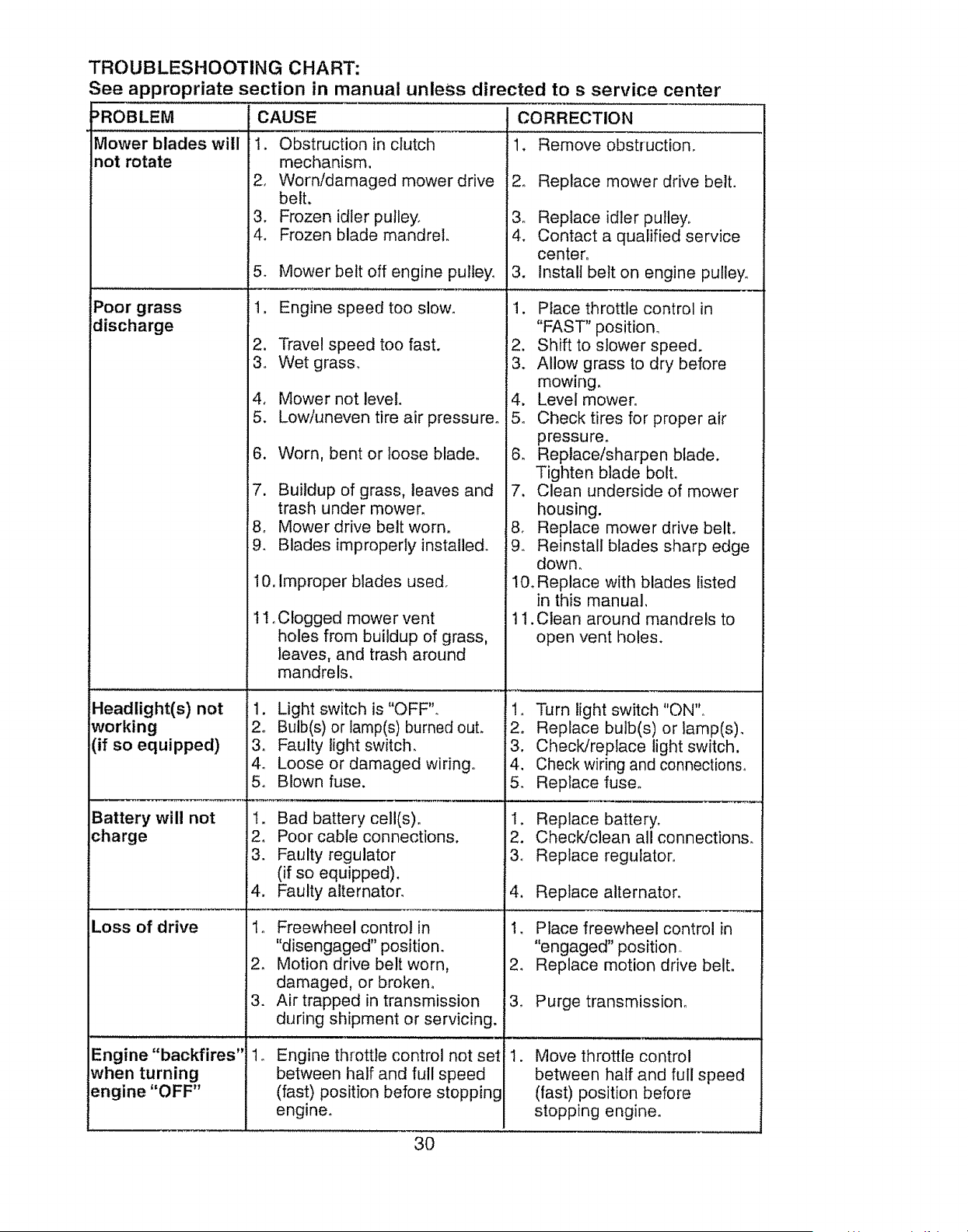
TROUBLESHOOTING CHART:
See appropriate section in manual unless directed to s service center
:_ROBLEM CAUSE CORRECTION
1, Remove obstruction.
Mower blades will
not rotate
Poor grass
discharge
Headlight(s) not
:working
(if so equipped)
Battery will not
charge
Loss of drive
Engine "backfires"
when turning
engine "OFF"
1. Obstruction in clutch
mechanism.
2. Worn/damaged mower drive
belt.
3. Frozen idler pulley.
4. Frozen blade mandrel.
5. Mower belt off engine pulley.
1. Engine speed too slow.
2. Travel speed too fast.
3o Wet grass.
4, Mower not level.
5. Low/uneven tire air pressure°
6. Worn, bent or loose blade.
7. Buildup of grass, leaves and
trash under mower.
8. Mower drive belt worn.
9. Blades improperly installed.
10. Improper blades used.
1t. Clogged mower vent
holes from buildup of grass,
leaves, and trash around
mandrels.
1. Light switch is "OFF".
2. Bulb(s) or lamp(s) burned out.
3o Faulty light switch.
4. Loose or damaged wiring°
5o Blown fuse.
t. Bad battery cell(s).
2, Poor cable connections,
3. Faulty regulator
(if so equipped).
4. Faulty alternator.
1o Freewheel control in
"disengaged" position.
2. Motion drive belt worn,
damaged, or broken°
3. Air trapped in transmission
during shipment or servicing.
Engine throttle control not set
between half and full speed
(fast) position before stopping
engine.
2_
4.
.
Replace mower drive belt.
Replace idler pulley.
Contact a qualified service
center.
Install belt on engine pulley,
1. Place throttle control in
"FAST" position.
2, Shift to slower speed.
3. Allow grass to dry before
mowing.
4, Level mower.
5o Check tires for proper air
pressure.
6. Replace/sharpen blade.
Tighten blade bolt.
7, Clean underside of mower
housing.
8. Replace mower drive belt,
9. Reinstall blades sharp edge
down.
I0_ Replace with blades listed
in this manual,
11 .Clean around mandrels to
open vent holes.
1. Turn light switch "ON".
2. Replace bulb(s) or lamp(s).
3, Check/replace light switch,
4. Check wiring and connections.
5. Replace fuse.
1. Replace battery,
2. Check/clean all connections.
3o Replace regulator,,
4. Replace alternator.
1_ Place freewheel control in
"engaged" position
2. Replace motion drive belt.
3. Purge transmission_
!1. Move throttle control
between half and full speed
(fast) position before
stopping engine.
3O
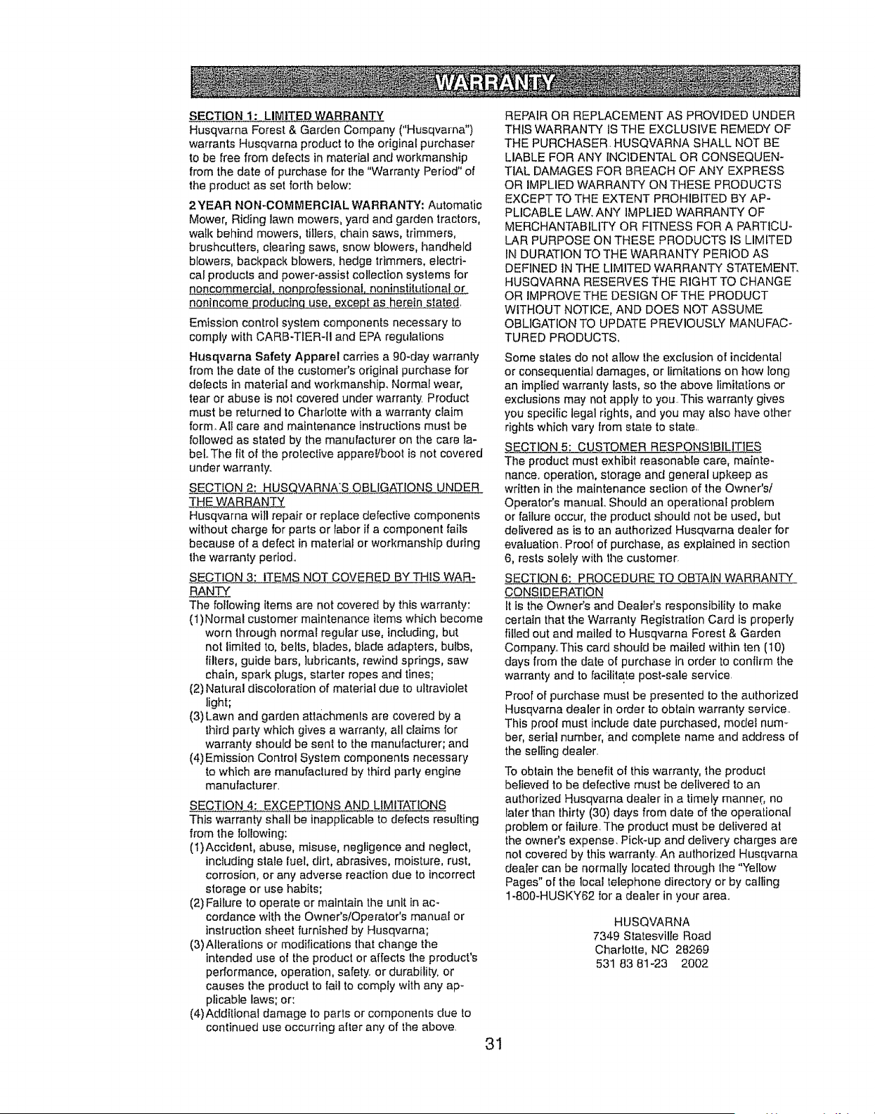
SECTION 1: LIMITED WARRANTY
Husqvarna Forest & Garden Company ("Husqvarna")
warrants Husqvarna product to the original purchaser
to be free from defects in material and workmanship
from the date of purchase for the "Warranty Period" of
the product as set forth below:
2YEAR NO N-COMMERCIAL WARRANTY: Automatic
Mower, Riding lawn mowers, yard and garden tractors,
walk behind mowers, tillers,chain saws, trimmers,
brushcutters, clearing saws, snow blowers, i_andheld
blowers, backpack blowers, hedge trimmers, electri-
cal products and power-assist collection systems for
noncommercial, nonl3rofessionai, noninst!tutiona_ or
nonincome produc!nq use. except as herein stated.
Emission control system components necessary to
comply with CARB-TtER-tl and EPA regulations
Husqvarna Safety Apparel carries a 90-day warranty
from the date of the customer's original purchase for
defects in material and workmanship.. Normai wear,
tear or abuse is not covered under warranty Product
must be returned to Charlotte with a warranty claim
form. All care and maintenance instructions must be
followed as stated by the manufacturer on the care ta-
beLThe fit of the protective apparelJboot is not covered
under warranty.
SECTEON 2: HUSQVARNAS OBLIGATIONS UNDER
THE WAR RANTY
Husqvarna will repair or replace defective components
without charge for parts or labor if a component fails
because of a defect in materiat or workmanship during
the warranty period..
SECTION 3: ITEMS NOT COVERED BYTHIS WAR-
RANTY
The following items are not covered by this warranty:
(1)Normal customer' maintenance items which become
worn through normal regular use, including, but
not limited to, belts, blades, blade adapters, bulbs,
tilters, guide bars, lubricants, rewind springs, saw
chain, spark plugs, starter ropes and tines;
(2) Natural discoloration of material due to ultraviolet
light;
(3) Lawn and garden attachments are covered by a
third party which gives a warranty, ail claims for
warranty should be senl to the manufacturer; and
(4)Emission Control System components necessary
to which are manufaclured by third parly engine
manufacturer.
SECTION 4: EXCEPTIONS AND LIMITATIONS
This warranty shall be inapplicable to defects resulting
from the following:
(1)Accident, abuse, misuse, negligence and neglect,
including stale fuel, dirt, abrasives, moisture, rust,
corrosion, or any adverse reaction due to incorrect
storage or use habits;
(2) Failure to operate or maintain the unit in ac-
cordance with the Owner's/Operator's manual or
instruction sheet furnished by Husqvarna;
(3) Alterations or modifications that change the
intended use of the product or affects the product's
performance, operation, safety, or durability, or
causes the product to fail to comply with any ap-
plicable laws; or:
(4)Additional damage to parts or components due to
continued use occurring after any of the above.
REPAIR OR REPLACEMENT AS PROVIDED UNDER
THIS WARRANTY IS THE EXCLUSIVE REMEDY OF
THE PURCHASER. HUSQVARNA SHALL NOT BE
LIABLE FOR ANY INCIDENTAL OR CONSEQUEN-
TIAL DAMAGES FOR BREACH OF ANY EXPRESS
OR IMPLIED WARRANTY ON THESE PRODUCTS
EXCEPT TO THE EXTENT PROHIBITED BY AP-
PLICABLE LAW. ANY IMPLIED WARRANTY OF
MERCHANTABILITY OR FITNESS FOR A PARTICU-
LAR PURPOSE ON THESE PRODUCTS IS LIMITED
IN DURATION TO THE WARRANTY PERIOD AS
DEFINED lN THE LIMITED WARRANTY STATEMENT,
HUSQVARNA RESERVES THE RIGHT TO CHANGE
OR IMPROVE THE DESIGN OF THE PRODUCT
WITHOUT NOTICE, AND DOES NOT ASSUME
OBLIGATION TO UPDATE PREVIOUSLY MANUFAC-
TURED PRODUCTS,
Some states do not allow lhe exclusion of incidental
or consequential damages, or limitations on how long
an implied warranty fasts, so the above limitations or
exclusions may not apply to you_This warranty gives
you specific legal rights, and you may also have other
rights which vary from state to state.
SECTION 5: CUSTOMER RESPONSIBILITIES
The product must exhibit reasonable care, mainte-
nance, operation, storage and general upkeep as
written in the maintenance section of the Owner's/
Operator's manual.. Should an operationaE problem
or failure occur, the product should not be used, but
delivered as is to an authorized Husqvarna dealer for
evaluation. Proof of purchase, as explained in section
6, rests solely with the customer,
SECTION 6: PROCEDURE TO OBTAIN WARRANTY
CONSIDERATION
It is the Owner's and Dealer's responsibility to make
certain that the Warranty Registration Card is properly
filled out and mailed to Husqvarna Forest & Garden
Company_ This card should be mailed within ten (10)
days from the date of purchase in order to confirm the
warranty and to facilitate post-sale service.
Proof of purchase must be presented to the authorized
Husqvarna dealer in order to obtain warranty service..
This proof must include date purchased, model num-
ber, serial number, and complete name and address of
the seFlingdealer.
To obtain the benefit of this warranty, the producl
believed to be defective must be deIivered to an
authorized Husqvama deaIer in a timely manner, no
later than thirty (30) days from date of the operational
problem or failure..The product must be delivered at
the owner's expense. Pick-up and delivery charges are
nol covered by this warranty. An authorized Husqvarna
dealer can be normally located through the "Yellow
Pages" of the toca_telephone directory or by coifing
1-800-HUSKY62 for a dealer in your area_
HUSQVARNA
7349 Statesville Road
Charlotte, NC 28269
531 83 81-23 2002
31
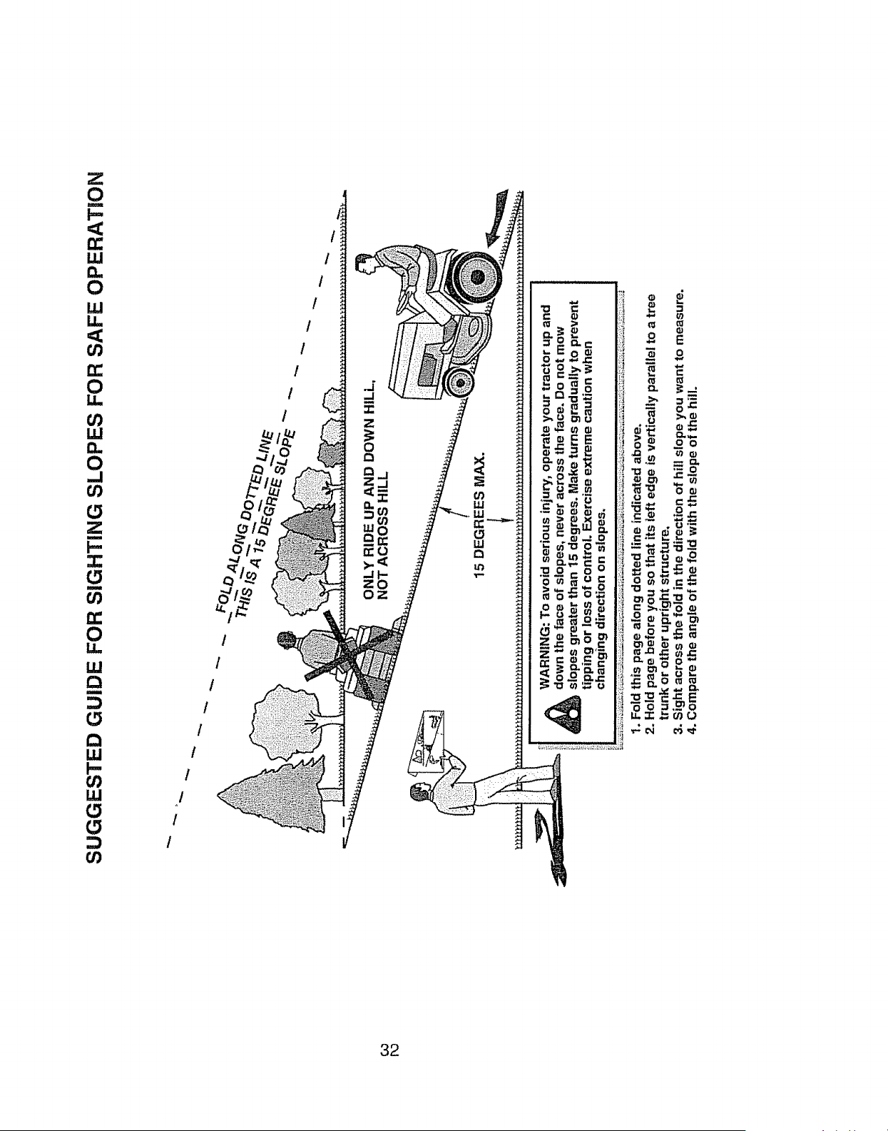
0
<
t_
1.1J
0
W
LI.
<
03
rr
0
LI.
ILl
0
.,,I
oO
0
m
!-
=
I
oO
D:
0
LU
R
t_
LU
I-
W
t_
t_
u)
I
!
i
I
I
t
I
0
Q
Q
I
I
I
i t
t
1
32
_PELIGRO: Esta Maquina cortadora es capaz de amputar las manosy los pies y de lanzar
objetos, si no se observan las tnstrucciones de seguridad stguientes se pueden producir
lesiones graves o la muerteo
_ADVERTENCIA: Siempre desconecte et
alambre de la bujfa y p6ngalo donde no pueda
entrar en contacto con la bujfa, para evitar el
arranque por accidente, durante la preparaci6n,
el transporte, el ajuste o cuando se hacen
reparaciones..
,_ADVERTENCIA: No avarice cuesta aba]o a
punto muerto ya que podr[a perder el control
del tractor.
,_ADVERTENClA: Remolque sofamente los
acceserios recomendados y conformes a las
caracter[sticas indicadas por el fabricante de
su tractor. Tenga cuidado y prudencia al utilizar
el tractor. Cuando se encuentre en un declive,
oper utitizando exclusivamente la vefocidad
m#,s baja,. En caso de un declive una carga ex-
cesiva podr[a resultar peligrosa. Los neum__ti-
cos pueden perder la tracci6n con el suelo y
hacerte perder el control de su tractor.
_ADVERTENCIA: El tubo de escape del
motor, algunos de sus constituyentes y algunos
componentes del veh[cuto contienen o despren-
den productos qu[micos conocidos en el Estado
de California como causa de cancer y defectos
al nacimiento u otros daSos reproductivo&
_,ADVERTENClA: Los bornes, terminales y
accesorios relativos de la bater[a contienen
ptomo o compuestos de plomo, productos
qu[micos conocidos en el Estado de California
como causa de c&ncer y defectos al nacimiento
u otros dafios reproductivos. Lavar las manos
despu_s de manipularlos.
I. FUNClONAMtENTO GENERAl.
oLeer, entender y seguir todas las instruccio-
nes sobre ta m&quina yen el manual antes
de empezar.
• No poner las manos o los pies cerca de
partes giratorias o debajo de la m&quina_
mantener siempre timpia la abertura de
descarga,
° Permitir el funcionamiento de la m#.quina
s61o a adultos que tengan familiaddad con
las instruccioneso
o Limpiar el ,_rea de objetos como piedras,
juguetes, cables, etc, que pueden set recogio
dos y disparados con las cuchillas_
. Asegurarse de que el &rea est6 tibre de otras
personas antes de ponerla en march& Parar
la rn_quina si alguien entra en el Area.
. Nuncallevar pasajeros
• No cortar marcha atr#.s at no ser absolu-
tamente necesado. Mirar siempre abajo y
delante mientras se procede atr4s..
•Nunca dirigir et material descargado hacia
nadieo Evitar descargar material contra
paredes u obstrucciones. El material podrfa
rebotar hacia el operador_ Parar las cuchillas
cuando se pasan superficies de grava
• No hacer funcionar la m_.quina sin el
captador de hierba entera, la protecci6n de
descarga u otros dispositivos de seguridad
en su lugar yen buenas condiciones.
. Ralentizar antes de girar.
° Nunca dejar una m_quina encendida sin vigi-
lancia,. Apagar siempre las cuchiIIas, poner el
freno de estacionamiento, parar el motor, y
quitar las IIaves antes de bajar.
•Desconectar las cuchiflas cuando no se
corta Apagar et motor y esperar que todas
las partes est_n completamente paradas
antes de limpiar la m_quina, quitar el capta-
dor de hierba, o desatascar la protecci6n de
descarga,
o Hacer funcionar la m_.quina s61o con fa luz
del d[a o luz artificial buena.
• No hacer funcionar la mAquina estando bajo
los efectos de alcohol o droga.
•Porter atenci6n al trAfico cuando se opera
cerca de calles o se cruzan,
° Poner ]a m&xtma atenci6n al cargar o descar-
gar la m_quina en una caravana o cami6n.
• Llevar siempre gafas de protecci6n cuando
se hace funcionar la m_.quina.
° Los datos indican que los operadores a
partir de los 60 afios est4.n afectados por
un gran porcentaje de heddas relativas a la
conducci6n del cortac_sped. Estos opera-
dores tenddan que evaluar su habilidad de
hacer funcionar et cortac_sped de modo Io
bastante seguro para proteger a sl mismos y
a otras personas de heridas graves.
• Seguir las recomendaciones del fabricante
para los pesos y contrapesos de las ruedas.
• Mantener la m#.quina fibre de hierba, hojas
u otros escombros que pueden tocar el
tubo de escape /partes del motor calientes
y quemarse. No permitir que el puente del
cortacesped cargue hojas u otros residuos
que pueden causar acumulaciones. Limpiar
toda salpicadura de aceite o carburante an-
tes de hacer operaciones sobre la m#.quina o
guardarI& Dejarla enfriar antes de guardarla.
II. FUNCIONAMIENTO EN PENDIENTES
Las pendientes son ef mayor factor de acciden-
tes relativos a la p_rdida de control y vuelco,
que pueden causar severas heridas o muerte_
El funcionamiento en pendientes requiere una
atenci6n extra, Si no es posibte hacer marcha
arras en una pendiente o si te sientes inco-
modo, no la cortes.
° Cortar hacia arriba y abajo de una pendiente,
no de modo horizontal°
•Poner atenciones a los hoyos, las ra[ces, los
bultos, las piedras u otros objetos escon-
didos. E1terreno irregular puede votcar la
m#,quina. La hierba alta puede esconder
obst_culos,
33
.Escoger una velocidad de marcha baja de
modo que no sea necesario pararse o cam-
btar estando en una pendiente.,
• No cortar ta hierba mojadao Las ruedas
pueden perder tracciSn.
Poner siempre una marcha cuando se est,.
en pendientes. No poner en punto muerto e
ir cuesta abajo_
• Evitar arrancar, pararse o girar en una
pendienteo Si las ruedas pierden tracci6n,
desconectar las cuchillas y proceder despa-
cio cuesta abajo en la pendiente.
• Mantener todo los movimientos en las pen-
dientes lentos y gradual° No hacer cambios
repentinos de velocidad o direcciSn, ya que
pueden causar el escape de la m_.quina.
•Porter la maxima atenciSn cuando la m_.-
quina funciona con captadores de hierba
u otros dispositivos enganchados; pueden
afectar la estabilidad de la m_quina. No usar
en pendientes empinados.
• No intentar estabilizar la m_quina poniendo
el pie en el terreno.
° No cortar cerca de bajadas, cunetas y orittas.
Las m_.quina puede volcarse improvisamente
si una rueda est_ en el borde o se hunde..
I11.NINOS
Si el operador no pone atenci6n a la presencia
de los niSos pueden ocurrir accidentes tr_gicos.
Los ni5os a menudo est_,n atrafdos por la m_.-
quina y las actividad de cortar. No dar per hecho
de que los niSos se queden adonde estaban la
_itima vez que los visteso
• Mantener los nfRos fuera del &rea de corte y
vigilados por un adulto responsable que no
sea el operador,
• Estar alerta y apagar la mAquina si un nihos
entra en el _.rea.
° Antes y durante la marcha atrb,s, mirar adel-
ante y abajo para vet si hay nfRos pequeRos.
.Nunca Ilevar niRos, incluso si hay tas
cuchillas apagadas. Podrfan caer y herirse
seriamente o interferir con el funcionamiento
seguro de la m_.quinaolos niSos que se ban
llevado precedentemente pueden aparecer
de pronto en el _rea de corte pot otro paseo
y ser atropellados o tumbados por la m_-
quina.
• Nunca dejar que los niSos rnanipulen la
m_.quina°
• Tener el m_.ximo cuidado cuando se acerca
a cantos ciegos, arbustos, ,¢rboles u otros
objetos que pueden impedir la vista de ni5os.
IV. REMOLQUE
• Remolcar s61o con una m,_quina que
tenga un gancho dise5ado para remolcar.
Enganchar el equipo o remotcar s6to en e!
punto dispuesto al efecto.
• Seguir las recomendaciones del productor
con respecto a los I[mltes def equipo por
remolcar y el remolque en pendienteso
• Nunca permitir que niP,os u otras personas
est6n dentro del equipo por remolcar.
,, En pendientes, el peso det equipo remolcado
puede causar ta p_rdida de tracci6n y la
p6rdida de control.
• Viajar despacio y dejar mb,s distancia para
frenan
V. SERVIClO
MANIPULACION SEGURA DE LA GASOLINA
Para evitar heridas personales o daRos alas
cosas, poner el m_ximo cuidado a la hora de
manipular la gasolina. La gasolina es extrema*
mente inflamable y los vapores son explosivos,
° Apagar todos los cigarriltos, cigarros, pipas y
otras fuentes de ignici6n,.
,Usar s61o contenedores para gasolina apro-
bados
•Nunca quitar el tap6n de la gasolina o aSadir
carburante con el motor en marcha, dejar
enfriar el motor antes del abastecimiento de
la gasolina.
° Nunca abastecer la m_,quina al interior de un
local.
° Nunca guardar la m#,quina o el contenedor
del carburante donde haya una llama abierta,
chispas ouna fuz piloto como un calentador
de agua u otros dispositivos,
°Nunca llenar los contenedores al interior de
un vehfculo o en una caravana o camiSn
recubiertos con un forro de pl&stico,, Cotocar
siempre los contenedores en el terreno lejos
del vehlcuto cuando se est_ llenando.
=Quitar el equipo de gas del cami6n o cara-
vana y abastecerto en el terreno, Si no es
posible, abastecer dtcho equipo con un con-
tenedor port_.til, m_s bien que de un surtidor
de gasolina.
° Mantener la boquilla a contacto del borde
det dep6sito de carburante o la abertura del
contenedor durante toda la operaci6n de
abastecimiento,. No utilizar un dispositivo con
boquilla cerrada-abierta.
•Si se vierte carburante sobre la ropa, cambi-
arse la ropa inmediatamenteo
° Nunca !lenar el dep6sito m_s de ]o debido.
Volver a colocar el tap6n del gas y cerrar de
modo firme,.
OPERAC1ONES DE SERVICIO GENERALES
° Nunca hacer funcionar la m_quina en un
_rea cerrada.
° Mantener todas las tuercas y pernos apre-
tados para asegurarse de que trabaja en
condiciones seguras.
, Nunca modificar los dispositivos de seguri-
dad. Controlar su correcto funcionamiento
regularmenteo
34
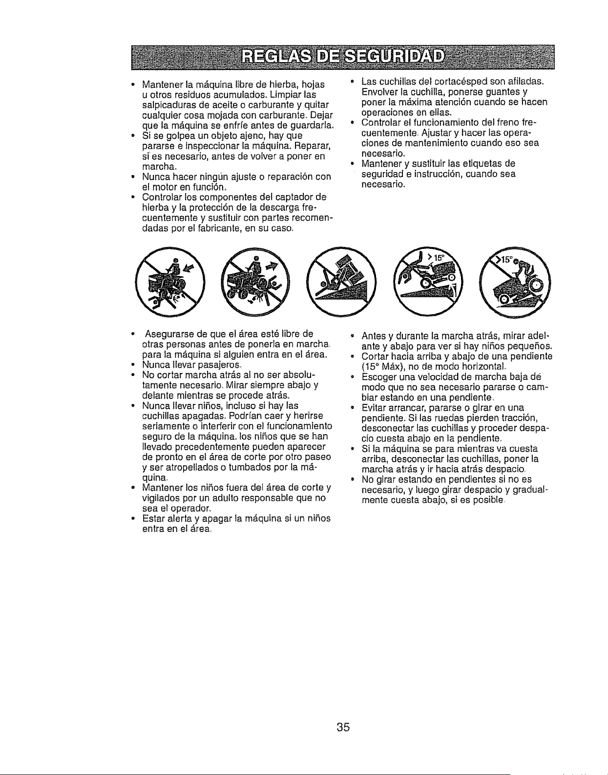
o Mantener la m&quina libre de hierba, hojas "
u otros residuos acumulado& Limpiar las
salpicaduras de aceite o carburante y quitar
cualquier cosa mojada con carburante. Dejar
que la mAquina se enfrfe antes de guardarla. °
Si se golpea un objeto ajeno, hay que
pararse e inspeccionar la m_quina. Reparar,
sies necesario, antes de volver a poner en
marcha_ °
• Nunca hacer ningun ajuste o reparaciSn con
el motor en funci6no
• Controlar los componentes del captador de
hierba y la protecci6n de la descarga fie-
cuentemente y sustituir con partes recomen-
dadas pot el fabricante, en su caso.
Las cuchillas del cortac6sped son afiladas.
Envolver la cuchitla, ponerse guantes y
porter la m_ima atencl6n cuando se hacen
operaciones en eltas.
Controlar el funcionamiento del freno fie-
cuentemente Aiustar y hacer las opera-
ciones de mantenimiento cuando eso sea
necesarioo
Mantener y sustituir las etiquetas de
seguridad e instrucci6n, cuando sea
necesarioo
o Asegurarse de que el Area est6 libre de
otras personas antes de ponerla en marcha
para la mAquina si alguien entra en el _.rea_
* Nuncallevar pasajeros.
- No cortar marcha atrAs al no set absolu-
tamente necesario.. Mirar siempre abajo y
delante mientras se procede arras,.
. Nunca Ilevar niSos, incluso si hay las
cuchillas apagadas. Podrfan caer y herirse
seriamente o interferir con el funcionamiento
seguro de la m&quina° los nifios que se ban
tlevado precedentemente pueden aparecer
de pronto en el Area de corte pot otro paseo
y ser atropellados o tumbados por la mA-
quina,
o Mantener los niRos fuera del Area de corte y
vigilados por un adulto responsable que no
sea el operador,
oEstar alerta y apagar la m_quina si un ni_os
entra en et Area.
° Antes y durante ia marcha atr,=f.s,mirar adel-
ante y abajo para ver si hay ni_,os peque5os.
• Cortar hacia arriba y abajo de una pendiente
(15° MAx), no de modo horizontal.
.Escoger una velocidad de marcha baja de
modo que no sea necesario pararse o cam-
biar estando en una pendiente,
o Evitar arrancar, pararse o girar en una
pendiente. Si las ruedas pierden tracciSn,
desconectar las cuchillas y proceder despa-
cio cuesta abajo en la pendiente.
.Si la mAquina se para mientras va cuesta
arriba, desconectar las cuchitlas, poner la
marcha atrAs y ir hacia arras despacio_
• No girar estando en pendientes si no es
necesario, y iuego girar despacio y gradual_
mente cuesta abajo, si es posib[e
35
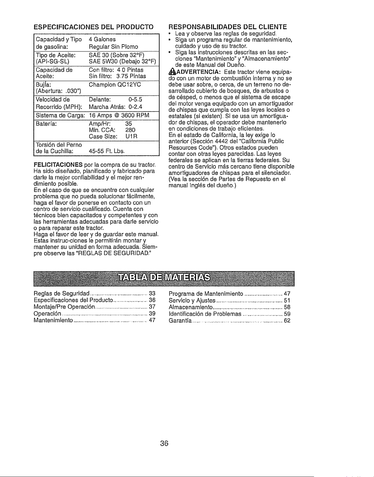
ESPECIFICACIONES DEL PRODUCTO
Capacidad yTipo 4 Galones
de gasolina: Regular Sin Plomo
Tipo de Aceite: SAE 30 (Sobre 32°F)
(API-SG-SL) SAE 5W30 (Debajo 32°F)
Capacidad de Con filtro: 4_0 Pintas
Aceite: Sin filtro: 3,75 Pintas
Bujfa: Champion QC12YC
(Abertura: ,030")
Ve!ocidad de Delante: 0-5,5
Recorrido (MPH): Marcha Atr#.s: 0-2.4
Sistema de Carga: 16 Amps @ 3600 RPM
Bater[a: AmpiHr: 35
Min, CCA: 280
Case Size: U1R
Torsi6n del Perno
de la Cuchilla: 45-55 Ft. Lbs,
FELIO1TAClONES por la compra de su tractor.
Ha sido diseRado, planificado y fabricado para
darle ta mejor confiabilidad y el mejor ren-
dimiento posibleo
En el caso de que se encuentre con cuatquier
problema que no pueda solucionar f_cilmente,
haga el favor de ponerse en contacto con un
centro de servicio cualificado. Cuenta con
t6cnicos bien capacitados y competentes y con
las herramientas adecuadas para dade servicio
o para reparar este tractor°
Haga e[ favor de leer y de guardar este manual
Estas instruc-ciones te permitir#.n montar y
mantener su unidad en forma adecuada, Siem-
pre observe las "REGLAS DE SEGURIDAD?
RESPONSABILIDADES DEL CLIENTE
• Lea y observe las reglas de seguridad..
• Stga un programa regular de mantenimiento,
cuidado y uso de su tractor°
•Siga las instrucciones descritas en las seo-
ciones "Mantenimiento" y "Almacenamiento"
de este Manual del Due5oo
_J_ADVERTENOIA: Este tractor viene equipa-
do con un motor de combusti6n interna y no se
debe usar sobre, o cerca, de un terreno no de-
sarrollado cubierto de bosques, de arbustos o
de c_sped, o menos que el sistema de escape
det motor venga equipado con un amortiguador
de chispas que cumpfa con las leyes locales o
estatales (si existen). Si se usa un amortigua-
dor de chtspas, el operador debe mantener]o
en condiciones de trabajo eficienteso
En el estado de California, la ley exige Io
anterior (SecciSn 4442 del "CaEffornia Public
Resources Code"), Otros estados pueden
contar con otras leyes parecidaso Las leyes
federales se aptican en la tierras federales, Su
centro de Servicto m_s cercano tiene disponible
amortiguadores de chispas para et silenciador,
(Vea la secci6n de Partes de Repuesto en el
manual lngt_s del duefio,)
Reglas de Seguridad .......................................33
Especificaciones del Producto ...................... 36
Montaje/Pre Operaci6n ................................ 37
Operaci6n ...................................................... 39
Mantenimiento ..................................................47
Programa de Mantenimiento ..........................47
Servicio y Ajustes ........................................ 51
Almacenamiento .......................................... 58
tdentificaci6n de Problemas ......................... 59
Garant[a ...........................................................................62
36
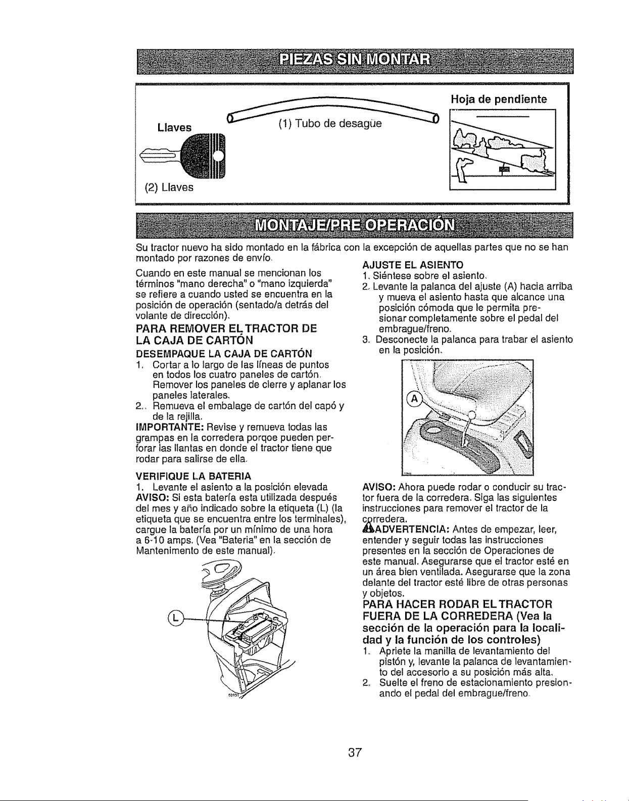
Llaves
11',1
(2) I_laves
(1) Tubo de desag_]e
Hoja de pendiente
Su tractor nuevo ha sido montado en la fAbrica con la excepci6n de aquellas partes que no se han
montado por razones de envfo.
Cuando en este manual se mencionan los
t6rminos "mano derecha" o"mano izquierda"
se refiere a cuando usted se encuentra en la
posiciSn de operaci6n (sentado/a detr_s del
volante de direcci6n)_
PARA REMOVER ELTRACTOR DE
LA CAJA DE CARTON
DESEMPAQUE LA CAJA DE CARTC)N
1, Cortar a Io largo de las Ifneas de puntos
en todos los cuatro paneles de cart6n,
Remover los paneles de cierre y aplanar los
paneles laterales.
2.. Remueva el embalage de cartSn del cap6 y
de la rejilla.
IMPORTANTE: Revise y remueva todas las
grampas en la corredera porqoe pueden per-
forar las Ilantas en donde et tractor tiene que
rodar para salirse de ella.
VER1FIQUE LA BATERIA
1. Levante el asiento a la posiciSn elevada
AVISO; Si esta baterfa esta utilizada despuels
del rues y afio indicado sobre la etiqueta (L) (la
etiqueta que se encuentra entre los terminales),
cargue la baterfa por un mfnimo de una hora
a 6d 0 amps, (Vea "Bateria" en la secci6n de
Mantenimento de este manual).
AJUS'rE EL ASIENTO
1, Si_ntese sobre el asiento,
2. Levante la palanca del ajuste (A) hacia arriba
y mueva el asiento hasta que alcance una
posici6n c6moda que le permita pre-
sionar completamente sobre el pedal del
embrague/freno.
3. Desconecte ia palanca para trabar el asiento
en la _ostci6n.
(
AVISO" Ahora puede rodar o conducir su trac-
tor fuera de la corredera. Siga las siguientes
instrucciones para remover el tractor de la
rAredera.
DVERTENClA: Antes de empezar, leer,
entender y seguir todas las instrucciones
presentes en la secci6n de Operaciones de
este manual Asegurarse que et tractor est6 en
un _.rea bien ventilada. Asegurarse que la zona
delante del tractor est_ libre de otras personas
y objetos.
PARA HACER RODAR EL TRACTOR
FUERA DE LA CORREDERA (Vea la
secci6n de la operaci6n para la Iocali-
dad y la funci6n de los controles)
1.. Apriete la maniila de levantamiento del
pist6n y, levante Eapalanca de levantamien-
to del accesorio a su posiciSn m,_s alta.
2. Suelte et freno de estacionamiento presion-
ando el pedal del embrague/freno..
37
3. Ponga el control de la rueda fibre en la
posiciSn de gko tibre para desenganchar
la transmisi6n+ (Vea "PARA TRANSPOR-
TAR" en la secci6n de Operaci6n de este
manual). (Vea "PARA TRANSPORTAR" en
la secci6n de Operaci6n de este manual).
4, Haga rodar el tractor hacia delante fuera de
la correderao
5, Remueva las bandas que sujetan la protec-
ci6n contra la descarga en contra del trac-
tor+
REMOVER ELTRACTOR DE LA PLATA-
FORMA (Vea la secci6n de la oper-
aci6n para ta Iocalidad y la funci6n de
los controles)
1. Asegurarse que se hayan completado toda
las fases del montaje,
2+ Controlar el nivel del aceite en el motor y
Ilenar el dep6sito con gasolina.
3+ Colocar el control de la rueda libre en la
posici6n "transmisi6n ocupada",
4+ Asentarse en la posici6n de guia, bajar el
pedal embrague/freno y colocar el freno de
mano,
5+ Apretar el _mbolo de la palanca de le-
vantamiento y levantar el dispositivo de la
palanca de levantamiento hasta su posici6n
m_.s alta,
6+ Tome la Ilave de la bolsa y arranque el mo-
ton (Ver "PARA ARRANCAR EL MOTOR"
en el capitulo de Manejo de este manual).
Despu6s de poner en marcha el motor
mover la palanca de! gas en posici6n neu-
tra°
7+ Quitar el freno de mano°
8+ Presione lentamente el pedal de mando
haoia adelante y guiar el tractor fuera de la
plataformao
9+ Actuar sobre el freno para parar el tractor y
colocar et freno de mano°
10_ Girar ta Ilave de encendido en la posici6n
"STOP"+
Contlnuar con las siguientes instrucciones+
REVISI()N DE LA PRESION DE LAS
LLANTAS
Las Ilantas en su unidad fueron infladas de-
masiado en la f_.brica por razones de env[o. La
presi6n de las tlantas correctas es importante
para obtener el mejor rendimiento en el corte+
oReduzca ta presi6n de los neum_.ticos a la
PSI que se indica en esto&
REVISION DE LA NIVELACtON DEL
CON JUNTO
Para obtener los meJores resultados en el corte,
la caja de la segadora tiene que estar nivelada
en la forma adecuada. Vea "PARA NIVELAR
LA CAJA DE LA SEGADORA" en la secci6n de
Servicio y.Ajustes de este manual.
REVISION DE LA POSiCION ADECUA-
DA DETODAS LAS CORREAS
Vea las figuras que aparecen para cambiar las
correas de impulsi6n de la cuchilla de la sega-
dora y de movimiento en ta secci6n de Servicio
y Ajustes de este manual. Verifique que las
correas sigan su paso correcto°
REVISION DEL SISTEMA DE FRENOS
Una vez que usted haya aprendido a mane-
jar su tractor, verifique que el freno funcione
correctamente, Ver"PARA VERfFICAR SI
FUNCIONA BIEN EL FRENO" en el capltulo de
servicio y ajustes de este manual+
v'LISTA DE REVISION
Antes de operar y de disfrutar de su trac-
tor nuevo, le deseamos que reciba el mejor
rendimiento y la mayor satisfaccion de este
producto de calidad,
Haga et favor de revlsar la lista a continuacion:
v" Se han completado todas las instrucciones
de montaje+
,/No quedan partes sueftas en la caja de
carton+
,/ La baterla est,. y cargada en
forma adecuad_ reparada
V' El asiento ha sido ajustado en forma c6moda
y apretado en forma segura+
v" Todas las Ilantas han sido infladas en forma
adecuadao (Para fines de env[o, las Ilantas se
inflaron demasiado en ]a f_,brica.)
€" AsegQrese que el conjunto segador est_
nivelado en forma adecuada, de lado a lado
desde adetante hacia atr_.s, para obtener
s mejores resultados en el corte+ (Las
tlantas tienen que estar infladas en forma
adecuada para fa nivelaci6n.)
,/ Revise las correas de impufsi6n y de la
segadora. Aseg_rese que recorran el paso
adecuado alrededor de las poleas y dentro
de todos los fijadores de lae correas.
,/Revise el alambrado,, Ffjese que todas ias
conexiones todavla est6n seguras y que los
alarnbres est_n sujetos en forma adecuada.
v" Antes de conducir el tractor, aseg6rese que
el control de rueda libre este en la posici6n
de "transmisi6n enganchada" (Vea "PARA
TRANSPORTAR" en la secci6n de la Oper-
aci6n de este manual).
At mismo tiempo que aprende a como usar su
tractor, preste atencion extra a los puntos de
impcrtancia que se presentan a continuacion:
¢" El aceite det motor tiene que Ilegar a! nivel
adecuado+
v" El estanque de combustible tiene que estar
lleno con gasotina sin plomo regular, nueva y
limpla.,
,,/ Familiarfcese con todos los controles - su
ubicaci6n y su funci6n, Op_relos antes de
hacer arrancar el motor,
,/AsegOrese que el sistema de frenos estO en
una condici6n de operaci6n segura+
V' Asegurarse de que el Sistema de
Presencia del Operador y el Sistema de
Funcionamiento Atr_.s (ROS) funcionan
de modo adecuado (Ver las Secciones de
Funcionamiento y Mantenimiento en este
manual).
v" Es importante purgar la transmisi6n antes
de operar su tractor por la primera vez, Siga
las instrucciones adecuadas para el empiezo
y para purgar (Vea "PARA EMPESAR EL
MOTOR" y "PARA PURGAR LA TRANSMIS-
ION" en la secci6n de la Operaci6n de este
manual.
38
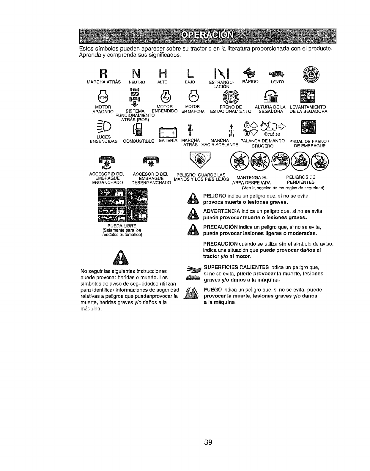
Estos sfmbolos pueden aparecer sobre su tractor o en la literatura proporcionada con el producto,,
Aprenda y comprenda sus significados.
R N H L
MARCHA ATRAS NEUTRO ALTO BAJO
" 6
MOTOR _ MOTOR MOTOR
APAGADO SISTEMA ENCENDIDO EN MARCHA
FUNC_ONAMIENTO
ATRAS (ROS)
LUCES
ENSENDIDAS
ACCESORIO DEL
EMBRAGUE
ENGANCHADO
ESTRANGU- Ri_PIDO LENTO
LACl6N
@) @
FRENO DE ALTURA DE LA
ESTACtONAMtENTO SEGADORA
COMBUSTIBLE
LEVANTAMIENTO
DE LASEGADORA
:BATERIA MARCHA MARCHA PALANCA DE MANDO PEDAL DE FRENO /
ATR,&,S HAClA ADELANTE CRUCERO DE EMBRAGUE
r#
ACCESORIO DEL
EMBRAGUE
DESENGANCHADO
RUEDA Lt8RE
(Sofamente para los
modetos autematico)
®@®@@
PELIGRO. GUARDE LAS
MANOS Y LOS PIES LEJOS MANTENGA EL PELtGROS DE
AREA DESPEJADA PENDIENTES
(Vea la secct6n de las reglas de seguridad)
PELIGRO tndica un peligro que, si no se evita,
provoca muerte o leslones graves,
ADVERTENCtA indica un peligro que, si no se evita,
puede provocar muerte o [esiones graves°
PRECAUCION indica un peligro que, si no se evita,
puede provocar lesiones ligeras o moderadas.
&
No seguir las siguientes instrucciones
puede provocar heridas o muerte. Los ,,_a_,_a.==.,=_
simbolos de aviso de seguridadse utilizan
para identificarinformaciones de seguridad _._9.
relativas a petigros que puedenprovocar la .
muerte, heridas graves yio daBos a la
m_quina.
PRECAUCION cuando se uttliza sin el simbolo de aviso,
indica una situaci6n que puede provocar daRos al
tractor ylo al motor.
SUPERFICIES CALIENTES indica un peiigro que,
st no se evita, puede provocar la muerte, leslones
graves y/o danos a la m&qutna.
FUEGO indica un pe_igro que, si no se evtta, puede
provocar la muerte, lesiones graves y/o danos
a la m_quina.
39
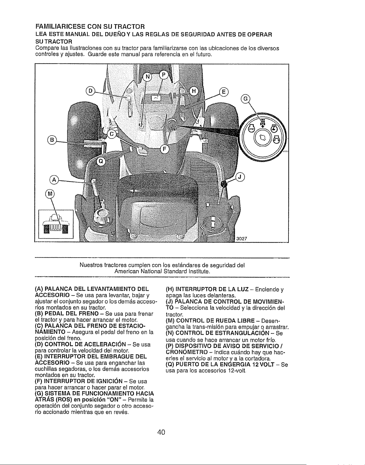
FAMILIARiCESE CON SU TRACTOR
LEA ESTE MANUAL DEL DUEb',IOY LAS REGLAS DE SEGURIDAD ANTES DE OPERAR
SU TRACTOR
Compare las ilustraciones con su tractor para familiarizarse con las ubicaciones de los diversos
controles y ajusteso Guarde este manual para referencia en el futuro_
Nuestros tractores cumplen con los est_.ndares de seguridad del
American National Standard institute°
(A) PALANCA DEL LEVANTAMIENTO DEL
ACCESORIO - Se usa para levantar, bajar y
ajustar e! conjunto segador o los dem_,s acceso-
dos montados en su tractor.
(B) PEDAL DEL FRENO - Se usa para frenar
el tractor y para hacer arrancar el motor,,
(C) PALANCA DEL FRENO DE ESTAClO-
NAMIENTO - Asegura el pedal del freno en la
posici6n del freno.
(D) CONTROL DE ACELERACION - Se usa
para controlar la velocidad del motor.
(E) INTERRUPTOR DEL EMBRAGUE DEL
ACCESORtO - Se usa para enganchar tas
cuchillas segadoras, o los dem_,s accesorios
montados en su tractor.
(F) INTERRUPTOR DE IGNICION - Se usa
para hacer arrancar o hacer parar el motor,.
(G) S.ISTEMA DE FUNCIONAMIENTO HAClA
ATRAS (ROS) en posicl6n "ON"- Permite la
operaci6n del conjunto segador o otro accesoo
rio accionado mientras qua en rev_s.
(H) tNTERRUPTOR DE LA LUZ - Enciende y
apaga las tuces detanteras.
(J) PALANCA DE CONTROL DE MOV1MIEN-
TO - Selecciona la vetocidad y la direcci6n del
tractor.
(M) CONTROL DE RUEDA LIBRE- Desen-
gancha la trans-misi6n para empujar o arrastrar.
(N) CONTROL DE ESTRANGULACION - Se
usa cuando se hace arrancar un motor frfo_
(P) DISPOSITIVO DE AVISO DE SERVlCIO /
CRONOMETRO - tndica cu&ndo hay que hac-
erfes el servicio al motor y a la cortadora,
(Q) PUERTO DE LA ENGERGIA '12VOLT- Se
usa para los accesorios 12-roll
4O
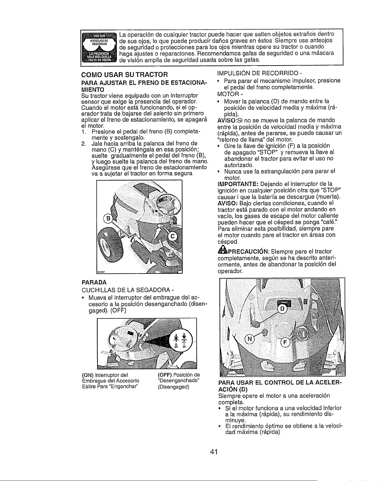
La operaciSn de cualquier tractor puede hacer que salten objetos extraSds dentro
de sus ojos, Io que puede producir daSos graves en {_stos Siempre use anteojos
de seguddad o protecciones para los ojos mientras opere su tractor o cuando
haga ajustes o reparacione& Recomendamos gafas de seguddad o una mascara
de visiSn amplia de seguridad usada sobre las gafas.
COMO USAR SU TRACTOR
PARA AJUSTAR EL FRENO DE ESTAClONA-
MIENTO
Su tractor viene equipado con un interruptor
sensor que exige [a presencia del operador.
Cuando el motor estA funcionando, si el op-
erador trata de bajarse del asfento sin pdmero
aplicar el freno de estacionamiento, se apagara
e/motor.
t. Presione el pedal det freno (B) completa-
mente y sostengaloo
2_ Jale hacia arriba la palanca det freno de
mano (C) y mant_ngala en esa posici6n;
suelte gradualmente el pedal del freno (B),
y luego sueite la palanca del freno de mano.
Asegt3rese que el freno de estacionamiento
va a sujetar et tractor en forma segura
PARADA
CUCHILLAS DE LA SEGADORA -
, Mueva el interruptor del embrague del ac-
cesodo a la posiciSn desenganchado (disen-
gaged). (OFF)
(ON) tnterruptor del
Embrague del Accesodo
Estire Para "Enganchar"
(OFF) Pos{ci6n de
"Desenganchado"
(D{sengagerJ)
IMPULSK_)N DE RECORRIDO -
• Para parar et mecanismo impu[sor, presione
el pedal del freno completamente.
MOTOR -
,Mover la palanca (D) de mando entre la
posicl6n de veloc]dad media y maxima (r_.-
pida).
AVISO:Si no se mueve la palanca de mando
entre la posici6n de velocidad media y m_x]ma
(rApida), antes de pararse, se puede causar un
"retorno de llama" del motor.
o Gire la Havede ]gnici6n (F) a ta posiciSn
de apagado "STOP" y remueva la ilave al
abandonar el tractor para evitar el uso no
autodzado.
, Nunca use la estranguLaci6n para parar el
motor.
IMPORTANTE: Dejando el interruptor de la
ignici6n en cualquier posici6n otra que "STOP"
causar i que la baterfa se descargue (muerta)o
AVISO: Bajo ciertas condiciones, cuando el
tractor estA parado con ef motor andando en
vacfo, los gases de escape de] motor calte'nte
pueden hacer que el c6sped se ponga "car&"
Para eliminar esta posibHidad, siempre pare
el motor cuando pare el tractor en Areas con
c_sped,
_PRECAUOI6N: Siempre pare el tractor
completamente, segf3n se ha descrito anteri-
ormente, antes de abandonar la posici6n del,
operadoro
PARA USAR EL CONTROL DE LA ACELER-
ACION (D)
Siempre opere el motor a una aceleraciSn
completa.
° Si et motor funciona a una velocidad inferior
a la maxima (rApida), su rendimiento dis-
minuye.
° El rendimiento 6primo se obtiene a la veloci-
dad maxima (r_,pida)
41
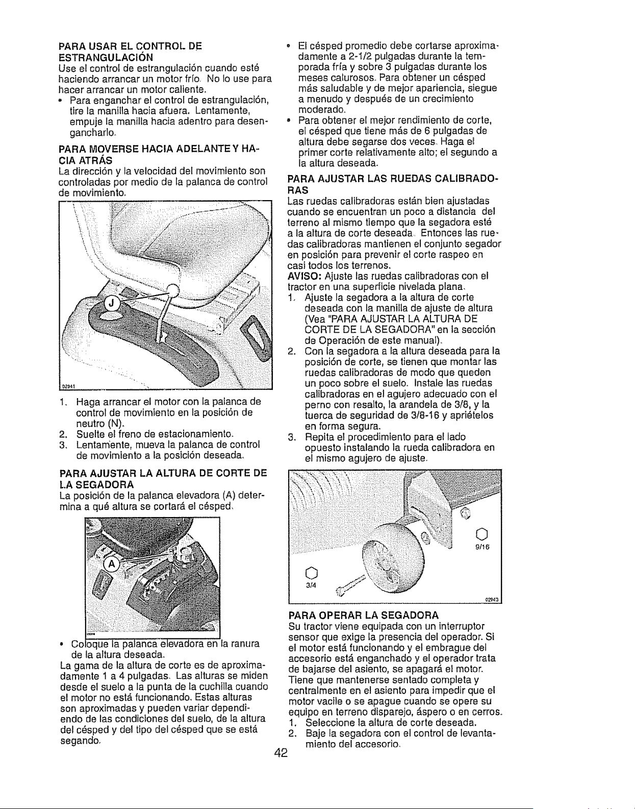
PARA USAR EL CONTROL DE
ESTRANGULACION
Use el control de estrangulaci6n cuando est6
haciendo arrancar un motor frfo. No !o use para
hacer arrancar un motor caltente.
• Para enganchar el control de estrangulaciSn,
tire la manitla hacia afuera. Lentamente,
empuje ta manilla hacia adentro para desen-
gancharlo.
PARA MOVERSE HACIA ADELANTE Y HA-
CIA ATR._,S
La direcci6n y la velocidad det movimiento son
controladas por medio de la palanca de control
de movimientoo
i /
I. Haga arrancar el motor con la palanca de
control de movimiento en la posici6n de
neutro (N)o
2. Suelte el freno de estacionamiento.
3_ Lentamente, mueva la palanca de control
de movimiento a la posici6n deseada_
PARA AJUSTAR LA ALTURA DE CORTE DE
l,A SEGADORA
La posici6n de la palanca elevadora (A) deter-
mina a qu6 altura se cortar_, el c6sped.
• Cc la ranura
de la attura deseadao
La gama de la altura de corte es de aproxima-
damente I a 4 pulgadas. Las alturas se miden
desde el suelo a la punta de la cuchitla cuando
el motor no est,. funcionando. Estas alturas
son aproximadas y pueden variar dependi-
endo de las condiciones del suelo, de la altura
del c_sped y del tipo del c6sped que se est&
segando.
o El c_.sped promedio debe cortarse aproxima-
damente a 2-I/2 pulgadas durante la tem-
porada frfa y sobre 3 pufgadas durante los
meses calurosos. Para obtener un cSsped
m&s saludable y de mejor apariencia, siegue
a menudo y despu_s de un crecimiento
moderado.
° Para obtener el mejor rendimiento de corte,
el c_sped que tiene m&s de 6 pulgadas de
altura debe segarse dos veces. Haga el
primer corte relativamente alto; et segundo a
Ia altura deseada.
PARA AJUSTAR LAS RUEDAS CALIBRADO-
RAS
Las ruedas calibradoras est&n bien ajustadas
cuando se encuentran un poco a distancia del
terreno al mismo tiempo que la segadora est6
a la altura de corte deseada.. Entonces las rue-
das catibradoras mantienen el conjunto segador
en posici6n para prevenir el corte raspeo en
casi todos los terrenos,
AVISO, Ajuste las ruedas calibradoras con el
tractor en una superficie nivelada plana.
1. Ajuste la segadora a ta altura de corte
deseada con la maniIta de ajuste de altura
(Vea "PARA AJUSTAR LA ALTURA DE
CORTE DE LA SEGADORA" en la secci6n
de Operaci6n de este manual),.
2. Con la segadora a la altura deseada para la
posici6n de corte, se tienen que montar las
ruedas calibradoras de mode que queden
un poco sobre el suelo, instate las ruedas
catibradoras en el agujero adecuado con el
perno con resalto, la arandela de 3/8, y la
tuerca de seguridad de 3/8-I6 y apri_telos
en forma segura.
3_ Repita el procedimiento para el lado
opuesto instalando la rueda calibradora en
el mismo agujero de ajusteo
©
9/16
©
3/4
PARA OPERAR LA SEGADORA
Su tractor viene equipada con [in interruptor
sensor que exige la presencia del operador. Si
el motor est,. funcionando y el embrague del
accesorio estA enganchado y el operador trata
de bajarse del asiento, se apagar,_ et motor.
Tiene que mantenerse sentado completa y
centralmente en el asiento para impedir que el
motor vacile o se apague cuando se opere su
equipo en terreno disparejo, Aspero o en cerros.
I. Seleccione la altura de corte deseada.
2. Baje la segadora con el control de levanta-
miento del accesorio.
42
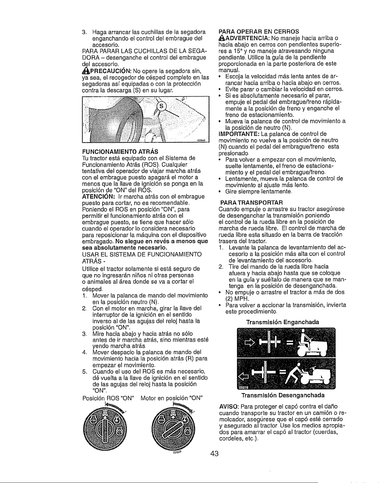
3+ Haga arrancar las cuchillas de fa segadora
enganchando et control del embrague del
accesorioo
PARA PARAR LAS CUCHILLAS DE LA SEGA-
DORA - desenganche el control del embrague
de! accesodo+
_J_PRECAUCI6N: No opere la segadora sin,
ya sea, el recogedor de c_sped completo en las
segadoras asf equipadas o con la protecciSn
contra la descarga (S) en su lugar,
FUNCIONAM1ENTO ATR/_,S
Tu tractor est,_ equipado con el Sistema de
Funcionamiento Atr#.s (ROS)+ Cualquier
tentativa del operador de viajar marcha atr,_s
con el embrague puesto apagar_, el motor a
menos que ta ilave de igniciSn se ponga en la
posiciSn de "ON" del ROS+
ATENCION: Ir marcha atr_ts con el embrague
puesto para cortar, no es recomendabte,
Poniendo el ROSen posici6n "ON", para
permitir el funcionamiento atr,_s con el
embrague puesto, se tiene que hacer s61o
cuando el operador Io considera necesario
para reposicionar la mAquina con el dispositivo
embragado. No siegue en rev_s a menos que
sea absolutamente necesario.
USAR EL StSTEMA DE FUNCiONAMIENTO
ATRAS -
Utilice el tractor solamente si est,. seguro de
que no ingresar,_n niRos ni otras personas
o animales al _rea donde se va a cortar el
c_sped.
1+ Mover la palanca de mando del movimiento
en la posiciSn neutro (N).
2+ Con el motor en marcha, girar la Ilave de!
interruptorde la ignici6n en el sentido
inverso at de [asagujas del reloj hasta la
posiciSn "ON".
3+ Mire hacta abajo y hacia atr6s no s6!o
antes de ir marcha atr,_s,sino mientras est_
yendo marcha atr#.s
4. Mover despacio la palanca de mando del
movimiento hacia la posiciSn atr#.s (R) para
empezar el movimiento.
5o Cuando el uso del ROSes m=Ssnecesario,
d6 vuelta a la ilave de igniciSn en et sentido
de las agujas det reioj basra la posfciSn
"ON"o
PosiciSn ROS "ON" Motor en posiciSn "ON"
PARA OPERAR EN CERROS
A_,ADVERTENCIA: No maneje hacia arriba o
hacia abajo en cerros con pendientes super]o-
res a 15°y no maneje atravesando ninguna
pendiente,. Utilice la gula de la pendiente
proporcionada en ta parte posteriora de este
manual,
• Escoja la velocidad mAs lenta antes de ar-
rancar hacia arriba o hacia abajo en cerroso
• Evite parar o cambiar la velocidad en cerros°
• Si es absolutamente necesario el parar,
empuje et pedal del embrague/freno r&pida-
mente a la posiciSn de freno y enganche el
freno de estacionamiento.
•Mueva la palanca de control de movimiento a
Ia posiciSn de neutro (N)°
IMPORTANTE: La palanca de control de
movimiento no vuelve a la posiciSn de +neutro
(N) cuando el pedal del embrague/freno esta
presionado.
• Para volver a empezar con el movimiento,
suelte lentamente, el freno de estaciona-
miento y el pedal det embrague/freno.
• Lentamente, mueva la palanca de control de
movimiento al ajuste m_s lento_
• Gire siempre lentamente.
PARA TRANSPORTAR
Cuando empuje o arrastre su tractor asegQrese
de desenganchar la transmisi6n poniendo
el control de la rueda libre en la posiciSn de
marcha de rueda libre. Et control de marcha de
rueda libre esta situado en la barra de tracciSn
trasera del tractor+
t_ Levante ta palanca de levantamiento del ac-
cesorio a la posiciSn m&s alta con ef control
de levantamiento del accesorio.
2+ Tire del mando de la rueda libre hacia
afuera y hacia abajo hasta que se coioque
en la gufa y su6ttalo de manera que se man-
tenga en _aposiciSn de desenganchada.
• No empuje o arrastre el tractor a mAs de dos
(2) MPH.
• Para volver a accionar la transmisiSn, invierta
este procedimiento.
Transmisi6n Enganchada
Transmtsi6n Desenganchada
AVtSO: Para proteger el cap5 contra el dar_o
cuando transporte su tractor en un camiSn o re-
molcador, asegt]rese que el cap5 est_ cerrado
y asegurado al tractor Use los medios apropia-
dos para amarrar el cap5 al tractor (cuerdas,
cordetes, etc.).
43
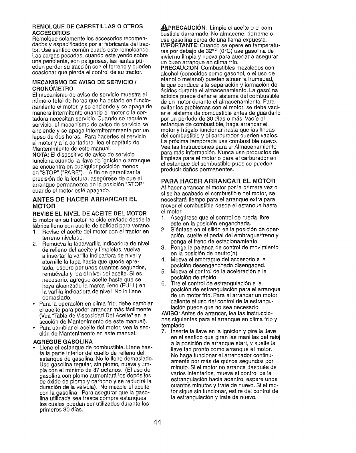
REMOLQUE DE CARRETILLAS O OTROS
ACCESORIOS
Remotque solamente los accesorios recomen-
dados y especificados per el fabricante del trac -
tot. Use senttdo comun cuado este remolcando.
Las cargas pesadas, cuando este yendo sobre
una pendiente, son peligrosas, las [lantas pu-
eden perder su tracci6n con el terreno y pueden
ocasionar que pierda el control de su tractor_
MECANISMO DE AVlSO DE SERVlCIO /
CRONOMETRO
El mecanismo de arise de servicio muestra el
nL_merototal de horas que ha estado en funcio-
namiento el motor, y se enciende y se apaga de
manera intermitente cuando el motor o la cor-
tadora necesitan servicio_ Cuando se requiere
servicio, el mecanismo de aviso de servicio se
enciende y se apaga intermitentemente per un
lapse de dos horas. Para hacerles el servicio
al motor y a la cortadora, lea el capftulo de
Mantenimiento de este manual,
NOTA: El dispositivo de aviso de servicio
funciona cuando ta Ilave de ignici6n o arranque
se encuentra en cuatquier posici6n menos
en "STOP" ("PARE")_ A fin de garantizar la
precisi6n de ta lectura, aseg_rese de que el
arranque permanezca en la posici6n "STOP"
cuando et motor est6 apagado_
ANTES DE HACER ARRANCAR EL
MOTOR
REVISE EL NIVEL DE ACEITE DEL MOTOR
El motor en su tractor ha side enviade desde la
f&brica Ileno con aceite de calidad para verano.
1o Revise el aceite del motor con el tractor en
terreno nivelado.
2. Remueva la tapaivarilla indicadora de nivel
de relleno de! aceite y tfmpietas, vuelva
ainsertar ta varilla indicadora de nivel y
atornille la tapa hasta que quede apre-
tada, espere per unos cuantos segundos,
remu6vala y lea el nivel de! aceite Si es
necesario, agregue aceite hasta que se
haya alcanzado la marca ILeno (FULL) en
la varitla indicadora de niveL No Io Hene
demasiadoo
• Para [a operaci6n en clima fifo, debe cambiar
el aceite para poder arrancar m_.s f&cilmente
(Vea '%abla de Viscosidad Del Aceite" en la
secci6n de Mantenimento de este manual)°
•Para cambiar el aceite del motor, yea la sec-
ci6n de Mantenimento en este manual.
AGREGUE GASOLINA
•Llene el estanque de combustible. Llene has-
ta la parte inferior del cuello de relleno del
estanque de gasolina, No Io Ilene demasiado,
Use gasolina regular, sin plomo, nueva y tim-
pia con el mfnimo de 87 octane& (Et use de
dgasolinacon plomo aumentar_, los dep6sitos
e 6xido de plomo y carbono y se reducir& la
duraci6n de la v&lvula). No mezcle el aceite
con la gasolina. Para asegurar que la gaso-
lina utiiizada sea fresca compre estanques
los cuales puedan ser utiltzados durante los
primeros 30 dfas,
_PRECAUCI6N: Limpie el aceite o el com-
bustible derramado. No aimacene, derrame o
use gasotina cerca de una llama expuesta_
IMPORTANTE: Cuando se opere en temperatu-
ras per debajo de 32°F (0"C) use gasolina de
invierno limpia y nueva para auedar a asegurar
un buen arranque en clima fr{o.
PRECAUCION: Combustibles mezclados con
alcohol (conocidos come gasohol, o el use de
etanol o metanol) pueden atraer la humedad,
la que conduce a la separaci6n y formaci6n de
_cidos durante el atmacenamiento, La gasolina
acfdica puede daSar e] sistema det combustible
de un motor durante el almacenamiento. Para
evitar los problemas con el motor, se debe vaci-
ar el sistema de combustible antes de guardario
per un perfodo de 30 dfas o m&s_Vacle et
estanque de combustible, haga arrancar el
motor y h6galo funcionar hasta que las llneas
det combustible y el carburador queden vacfo&
La pr6xima temporada use combustible nuevoo
Vea las Instrucciones para el AImacenamiento
ara m_s informaci6no Nunca use productos de
pieza para el motor o para el carburador en
el estanque del combustible pues se pueden
producir daSos permanente&
PARA HACER ARRANCAR EL MOTOR
AI hacer arrancar el motor per la primera vez o
si se ha acabado el combustible de! motor, se
necesitar_ tiempo para el arranque extra para
mover el combustible desde e! estanque basra
el motor.,
1. Asegl]rese que et control de rueda libre
este en la posici6n enganchada_
2. Si6ntase en el sill6n en la posici6n de oper-
aci6n, suelte el pedal del embrague/freno y
ponga el freno de estacionamiento.
3. Ponga la palanca de control de movimiento
en la posici6n de neutro(n),
4, Mueva el embrague del accesorio a la
posici6n desenganchado disengaged°
& Mueva el control de la aceleraci6n a ia
posici6n de r_.pido,
6, Tire el control de estrangulaci6n a fa
posici6n de estrangulaci6n para el arranque
de un motor fifo. Para el arrancar un motor
caliente el uso del control de la estrangu-
laci6n puede que no sea necesario,
AVlSO: Antes de arrancar, lea las instruccio-
nes siguientes para el arranque en clima frfo y
templadoo
7, lnserte la llave en la ignici6n y gire la llave
en el sentido que giran las mantIlas del reloj
a la posici6n de arranque start, y suelte la
llave tan pronto como arranque el motor,
No haga funcionar el arrancador continu-
amente por m_.s de quince segundos por
minuto. Si el motor no arranca despu6s de
varios intentarlos, mueva el control de la
estrangulaci6n hacia adentro, espere unos
cuantos minutos y trate de nuevo. Si el mo-
tor sigue sin funcionar, estire det control de
la estrangulaci6n y trate de nuevo,
44
ARRANQUE CON T1EMPO TEMPLADO (50 °
YMAS)
8, Cuando arranque el motor, empuje et con-
trol de la estrangulaci6n hasta que el motor
emplece a funcionar m_s suavemente, Si
el motor empieza a funcionar mat, estire
del control de la estrangulaci6n un poco
por unos cuantos segundos y entonces
continu_ a empujar lentamente el control,,
• Los accesorios y el embrague de suelo
ahora puede ser utilizado& Si el motor no
acepta esta carga, vuelva a arrancar el motor
para permitirle que se caliente por un minuto,
utilizando el estrangulador como describido
arriba.
ARRANQUE CON TIEMPO FRfO (50°Y
MENOS)
8, Cuando arranque el motor, empuje lenta-
mente el control de la estrangulaci6n hacia
adentro basra que el motor empiece a
funcionar suavemente. Siga empuj_ndolo
poco a poco permitiendo que el motor acepte
pequeSos cambios de velocidad y carga,
hasta que este completamente hacia aden-
fro. Si el motor empfeza a funcionar mal, es-
tire del control de la estrangulaci6n un poco
por unos cuantos segundos y continSe a
empujar el control hacia adentro. Esto puede
requerir que el motor se caliente pot unos
cuantos minutos, depende de la temperatura.
CALENTAMtENTO PARA LA TRANSMISION
AUTOMATfCA
Antes de conducir la unidad en un tiempo if[o,
la transmisi6n debe ser calentada como tas
instrucciones siguientes:
1. Asegt)rese que el tractor este situado en
una superficie nivelada.
2. Ponga la palanca de control en neutro.
Ativie el freno de estacionamiento y deje
que el embrague/freno vuelva a la posici6n
de operaci6n.
3. Permtta que la transmisi6n se caliente
durante un minuto. Esto puede ser echo du-
rante el tiempo de calentamiento del motor.
. Los accesorios pueden set utilizados durante
el periodo dei recatentamiento del mo-
tor despu_s que la transmisi6n halta stdo
calentada y puede requerir que el control de
la estrangulaci6n sea estirado un pocoo
AVISO: Si se encuentra a mucha altura (sobre
3000 pies) o en clima frfo (por debajo de 32°F
[0°C]), fa mezcla del combustible del carburador
debe ser ajustada para el mejor rendimiento
del motor. (Vea "PARA AjUSTAR EL CARBU-
RADOR" en fa secci6n de Servicio y Ajustes de
este manual).
PURGAR LA TRANSMtSION
_PRECAUCI6N: Nunca enganche o desen-
ganche la palanca del control de rueda tibre
cuando el motor esta funcionando,
Para asegurar la operaci6n y ejecuci6n adec-
uada, es recomendado que la transmisi6n sea
purgada antes de operar el tractor para la prim-
era vez. Este proceso removerS, cuatquier aire
adentro de la transmisi6n que se halIa formado
durante el transporte de su tractor.
IMPORTANTE: Si por acaso su transmisi6n
debe set removida para servicio o reempiazo,
debe ser purgada despu_s de la reinstalaci6n y
antes de operar el tractor°
1. Para mayor seguridad, ubique el tractor
en una superficie nivelada, despejada de
cualquier objeto y abierta, con et motor
apagado y el freno de mano puesto._
2o Desenganche la transmisi6n poniendo el
control de rueda libre en la posici6n de
desenganchado (Vea "PARA EL TRANS-
PORTE" en esta secci6n de este manual).
3o Sentado en el asiento dei tractor, empiece
el motor, Despu_s que este corriendo el
motor, mueva el control de estrangulaci6n
ata posici6n de lento., Con la palanca de
rueda Iibre en la posiciSn de neutral (N),
desenganche lentamente el embrague/el
freno del pedaf_
PRECAUCION: En el transcurso del paso 4,
puede que de pronto se pongan en movimiento
las ruedaso
4. Mueva la palanca det control de movimiento
a ia posici6n total de adelante y suj_tela
durante cinco (5) segundos. Mueva la
palanca hacia la posici6n total de marcha
arras y suj_tela durante cinco (5) segundos.
Repita este proceso tres (3) veces.
5. Mueva la palanca del control de movimiento
a la posici6n de neutro (N). Apague el motor
y embrague el freno de estacionamiento.
6. Enganche la transmisi6n poniendo et
control de rueda libre en la posici6n de
conducir (Vea "PARA TRANSPORTAR" en
esta secci6n def manual).
7, Sentado en el asiento del tractor, empiece
et motor, Despu6s que este corriendo el
motor, mueva et control de estrangulaci6n
media (1/2) velocidad. Con la palanca de
control de movimiento a la posici6n de
neutro (N), fentamente desenganche el
embrague/el freno del pedal,
8. Mueva Ientamente la palanca de control
de movimiento hacia adelante, despu6s
que el tractor se mueva aproximadamen-
te cinco (5) pies, mueva lentamente con
la palanca de control de movimiento a la
posici6n contraria. Despu6s que el tractor
se mueva aproximadamente unos cinco (5)
pies vuelva a poner ia palanca de control
de movimiento en la posici6n de neutro (N)o
Repita este procedimiento la palanca de
control de movimiento tres (3) veces.
Su transmtsi6n esta ahora purgado y dispuesto
para la operaci6n normal.
45
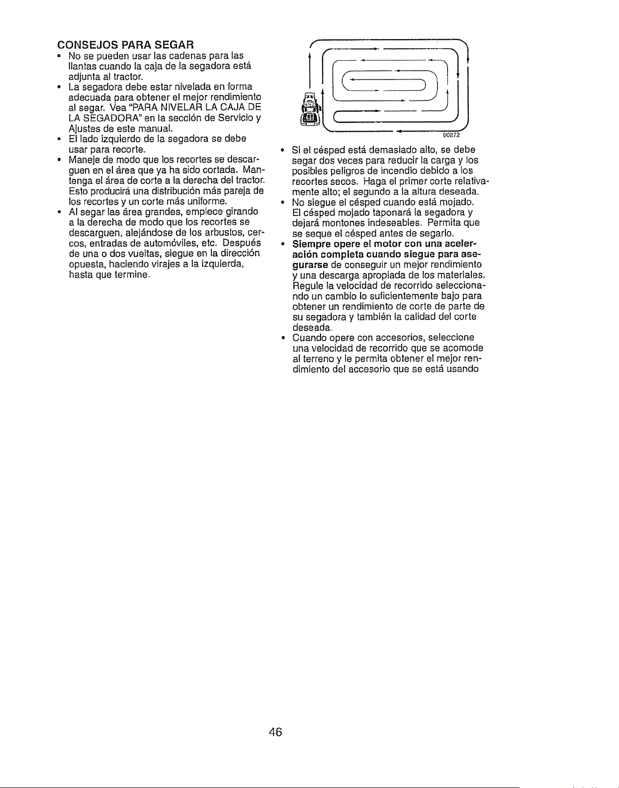
CONSEJOS PARA SEGAR
•No se pueden usar las cadenas para las
liantas cuando la caja de ta segadora estA
adjunta a! tractor°
•La segadora debe estar nivetada en forma
adecuada para obtener el mejor rendimiento
al segar. Vea "PARA NtVELAR LA CAJA DE
LA SEGADORA" en la secci6n de Servicio y
Ajustes de este manual
o El lado izquierdo de la segadora se debe
usar para recorteo
° Maneje de modo que los recortes se descar-
guen en el Area que ya ha sido cortada. Man-
tenga el Area de corte a la derecha del tractor.
Esto producirA una distribuci6n mAs pareja de
los recortes y un corte mAs unlforme.
. AI segar las Area grandes, empiece girando
a la derecha de modo que los recortes se
descarguen, alej_.ndose de los arbustos, cer-
cos, entradas de autom6viles, etco Despu6s
de una o dos vueltas, siegue en la direcci6n
opuesta, haclendo virajes a la izquierda,
hasta que termine.
f
J
00_72
• Si el c6sped estA demastado alto, se debe
segar dos veces para reducir la carga y los
posibles peligros de incendio debido a fos
recortes secos_ Haga el primer corte relativa-
mente alto; el segundo a la altura deseada,_
° No siegue el c6sped cuando est,_ mojado.
El c6sped mojado taponarA la segadora y
dejar_ montones indeseables. Permita que
se seque el c_sped antes de segarloo
° Siempre opere el motor con una aceler-
acl6n completa cuando siegue para ase-
gurarse de conseguir un mejor rendimiento
y una descarga apropiada de los materialeso
Regule la velocidad de recorrido selecciona-
ndo un cambio Io suficientemente bajo para
obtener un rendimiento de corte de parte de
su segadora y tambi6n la calidad del corte
deseada,.
•Cuando opere con accesorios, seleccione
una velocidad de recorrido que se acomode
al terreno y le permita obtener el mejor ren-
dimiento del accesorio que se estA usando.
46
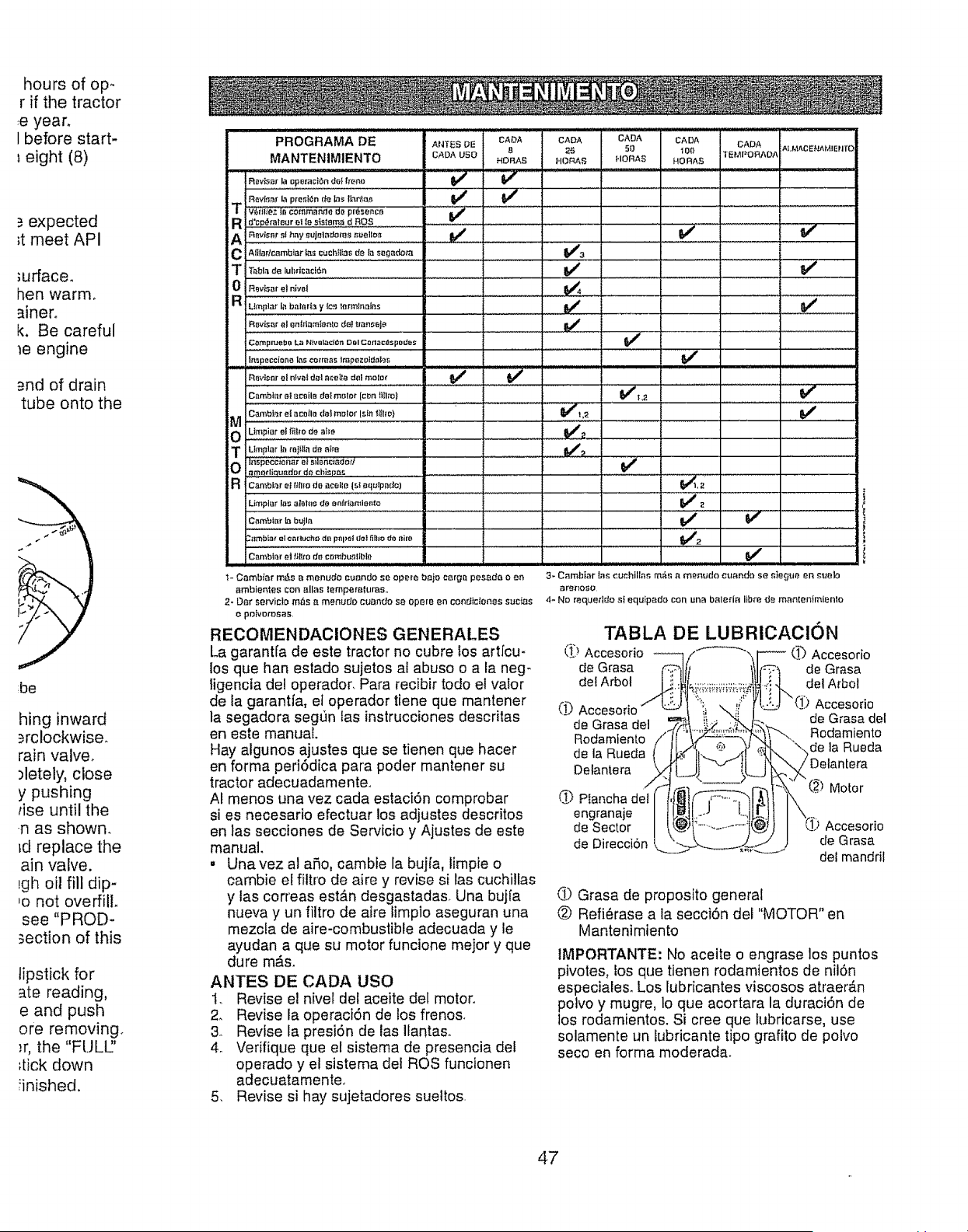
hours of op.
r if the tractor
e year.
I before start-
eight (8)
.=expected
;t meet API
;urface.
hen warm°
Wnero
k. Be careful
_e engine
_=ndof drain
tube onto the
be
hing inward
_=rclockwise.
rain valve.
)letely, close
y pushing
rise until the
.n as shown.
td replace the
ain valve.
lgh oit fill dip-
,o not overfill.
see "PROD-
section of this
lipstick for
ate reading,
e and push
ore removing.
;r, the "rULE'
_tick down
finished.
PROGRAMA DE ANTESDE
MANTENIMIENTO CADAusa
-Rov#;_r I-_OpBmci_n dO{ f_e_.o =
VC#ifie,Z IB€0mrnande do presence V_ "
R i d'cp_raleur e, te SisIsm. dROSRev_ar et hay Sujet,der_ r.uei!_._
el Al_larlc_mbl_r _s cuchFllas de la _egadera
T i Tabl_ de lubrlcmzi6n
0 i RevL_ar el nivel
a i Umplar In baft_r|_ yte_ tr'.rmInal#.s
RevJs_relentflamSet_te det _ra_eje
Cemp_ba L_ Nlva_{_m Dc, I Cor_ac_tspodes
lr_speceione las cmmas lr_#o_eJ_ei-.,_
CADA
8
HOI_S
V
CADA
_5
I,IORAS
CADA CADA CADA ALMACENAMIENTO
50 100 TEMPORAD.a
HORAS HORAS
..............., ' [ ................:
v%
v"
L,,,
Cambiar el a_eile deImelot (e_n flIIte)
a0e,;'o,,e,mo,o,,,,°,,,,,e, .... "............ ,i , ,
OLtrnpiar el_il_Ode alIe _##_
emediq_mdor de chlsp{_ .................
Limplar las aieles de enir[_.mie_e V_
Cambiar [abujla .................................... ,................. "' "_
._tlm_[z3_"el ¢_ltU_hf.) die p_pe! {leiflJtlO dO airs ......................... V_2
Camblar eJ _itl_o de eer_f;_z_qtibta
v'
v"
,,V'
v"
v"
1- Cambfat m#,s a menudo cuando se ope{e baio carga pesada oen 3- Cambiar [as cuchil[ar, m_s a menuda cuando se _tegue en ;uelo
arnbienies con alias lemperaluras., arenoso
2- Oar servicio m_s a menudo cuando se opera en condiciones sucias 4- Nm requeddm sI equlpado con una baleda Itbre de mamenfmlento
opo!vorosas,
RECOMENDACIONES GENERALES
La garant(a de este tractor no cubre los artfcu-
los que han estado sujetos al abuso o a la neg-
iigencta del operador, Para recibir todo el valor
de la garantla, et operador tiene qua mantener
la segadora seg_n las instrucciones descritas
en este manual,
Hay algunos ajustes qua se tienen que hacer
en farina peri6dica para poder rnantener su
tractor adecuadamente°
AI menos una vez cada estaci6n comprobar
si es necesario efectuar los adjustes descritos
en las secciones de Servicio y Ajustes de este
manual
. Una vez al ado, cambie la bujfa, limpie o
cambie el filtro de aire y revise si las cuchillas
y las correas estb,n desgastadas. Una buj[a
nueva y un filtro de aire limpio aseguran una
mezcta de abe-combustible adecuada y le
ayudan a qua su motor funcione mejor y que
dure m_.s.
ANTES DE CADA usa
I. Revise el nivel del aceite del motor.
2. Revise la operaci6n de los frenos.
3, Revise ta presi6n de las Ilantaso
4o Verifique que el sistema de presencia del
operado y el sistema del ROS funcionen
adecuatamente,,
5_ Revise si hay sujetadores sueltos
TABLA DE LUBRICACl()N
(_) Accesorio (_ Accesorio
de Grasa de Grasa
del Arbol dei A_bol
(1_ Accesorio Accesorio
de Grasa del de Grasa del
Rodamiento Rodamiento
de la Rueda de la Rueda
Detantera
Motor
_) Plancha del
engranaje
de Sector Accesorio
de Direccion de Grasa
del mandril
_) Grasa de proposito general
_.) Refi_rase a la secci6n del "MOTOR" en
Mantenimiento
IMPORTANTE: No aceite oengrase los puntos
pivotes, los que tienen rodamientos de nil6n
especiales. Los lubricantes viscosos atraer_.n
potvo y mugre, lo qua acortara la duraci6n de
los rodamientos. Si cree que lubricarse, use
solamente un lubricante tipo grafito de polvo
seco en forma moderada.
47
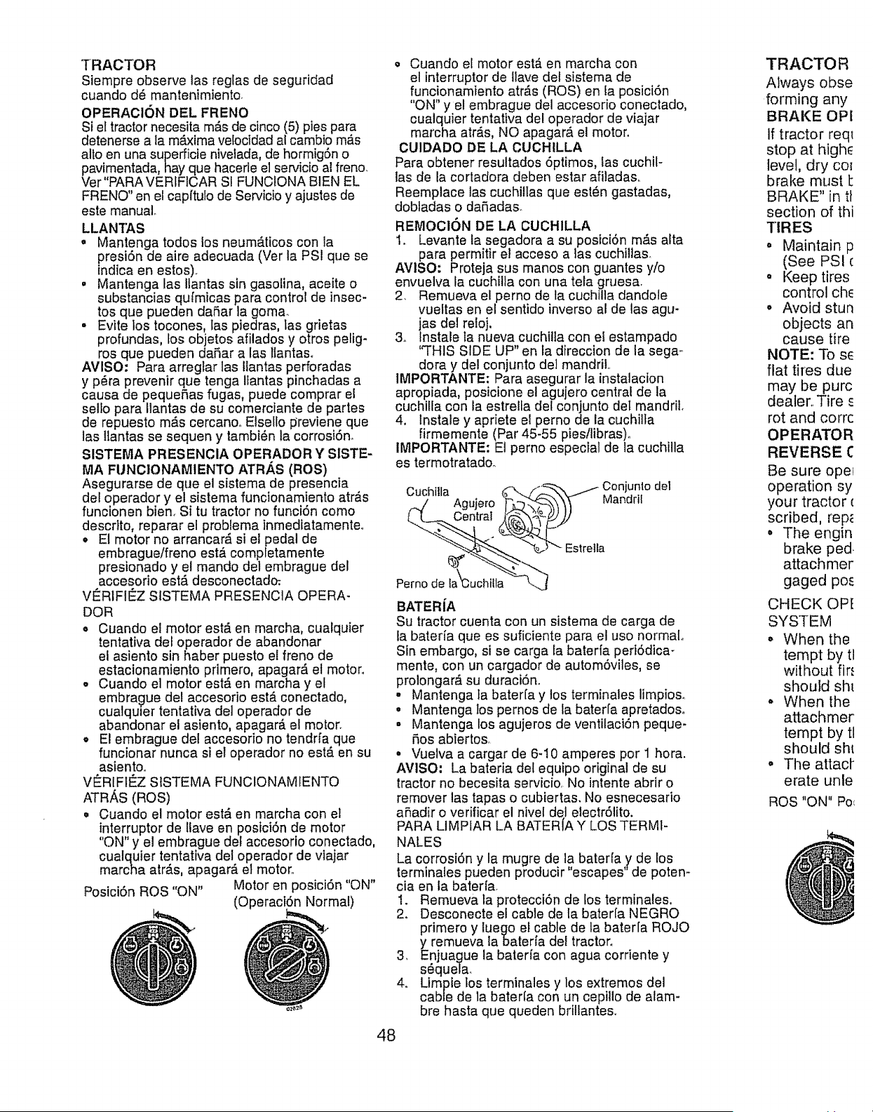
TRACTOR
Siempre observe las reglas de seguridad
cuando d6 mantenimiento.
OPERAOION DEL FRI=NO
Si el tractor necesita m_fsde cinco (5) pies para
detenerse ala m_xima velocidad al cambio m,_s
alto en una superficie nivelada, de hormigSn o
pavimenteda, hay que hacerle el servicio al franc.
Ver"PARAVERIFICAR SI FUNCIONA BIEN EL
FRENO" en el capffulo de Servicio y ajustes de
este manual
LLANTAS
° Mantenga todos los neum_tticos con la
presiSn de aire adecuada (Ver la PSI que se
indica en estos).
• Mantenga las llantas sin gasolina, aceite o
substancias qufmicas para control de insec-
tos que pueden daSar la goma.
• Evite los tocones, las piedres, Ias grietas
profundas, los objetos afilados y otros pelig-
ros que pueden daSar a las llantaso
AVlSO: Pare arreglar las llantas perforadas
y p_ra prevenir que tenga llantas pinchadas a
cause de pequefias fugas, puede comprar el
selto para Ilantas de su comerciante de partes
de repuesto mAs cercanoo Elsello previene qua
las ltantas se sequen y tambi6n la corrosiSn,
SISTEMA PRESENCIA OPERADOR Y SlSTE-
MA FUNCIONAMIENTO ATR,_,S (ROS)
Asegurarse de que el sistema de presencia
del operador y el sistema funcionamiento atr#,s
funcionen bien. Si tu tractor no funciSn como
descdto, reparar el problema inmediatamente**
• El motor no arrancar,_ si el pedal de
embrague/freno est#. completamente
presionado y el mando del embrague del
accesorio est,. desconectedo:
V_RIFIEZ SISTEMA PRESENCIA OPERA-
DOR
e Cuando el motor estA en marcha, cualquier
tentativa del operador de abandonar
el asiento sin haber puesto el freno de
estacionemiento primero, apager#, el motor°
• Cuando el motor est#. en marcha y el
embrague del accesorio est,. conectado,
cualquier tentative de] operador de
abandonar el asiento, apagarEi el motor.
• El embrague del accesoNo no tendrfa qua
funcionar nunca si el operador no est_ en su
asientoo
V_RtFtC:Z SISTEMA FUNCIONAMIENTO
ATRAS (ROS)
° Cuando el motor est,. en marcha con el
interruptor de llave en posici6n de motor
"ON" y el embregue del accesorio conectado,
cualquier tentativa dei operador de viajar
marcha atr_.s, apager_, el moton
Posici6n ROS "ON" Motor en posici6n "ON"
(OperaciSn Normal)
•Cuando el motor est_ en marcha con
e! interruptor de Iiave del sistema de
funcionamiento atr_s (ROS) en la posici6n
"ON" y el embrague del accesorio conectado,
cualquier tentativa del operador de viajar
marcha atr#.s, NO apagar#, el motor°
CUIDADO DE LA CUCHILLA
Pare obtener resultados 5ptimos, las cuchil-
las de la cortadora deben estar afiledas.
Reemplace las cuchillas que est_n gastadas,
dobladas o daRadas.
REMOCION DE LA CUCHILLA
I. Levante la segadora a su posiciSn m_s alta
pare permitir el acceso alas cuchillas.
AVlSO: Proteja sus manos con guantes y/o
envuelva la cuchilla con una tela gruesa.
2. Remueva el perno de ta cuchille dandole
vueltas en el sentido inverso al de las agu-
jas del reloj.
3o Instale la nueva cuchille con el estampado
"THIS SIDE UP" en la direccion de la sega o
dora y del conjunto de] mandril,.
IMPORTANTE: Pare asegurar la instalacion
apropiada, posicione el agujero central de la
cuchilla con fa estrelfa del conjunto det mandril.
4. lnstale y apriete el perno de la cuchilla
firmemente (Par 45-55 pies/libras).
IMPORTANTE: El perno especial de la cuchilta
es termotratado.
Cuchilta _/'.L.._--_'x_..-----"Conjun!odel
._../ Agujero "F'_.'3_,"_--'__ ",_ Manorll
BATER[A
Su tractor cuenta con un sistema de carga de
la bateria qua es suficiente pare el uso normal.
Sin embargo, si se carga la baterfa periddica-
mente, con un cargador de automSviles, se
prolongar,_ su duraciSn.
• Mantenga la baterla y los terminales limpioso
o Mantenga los pernos de la baterfa apretadoso
• Mantenga los agujeros de ventilaciSn peque-
P,os abiertos,
• Vuelva a cargar de 6-10 amperes por 1 hora.
AVISO: La bateria del equipo original de su
tractor no becesita servicio, No intente abrir o
remover las tapas o cubiertas. No esnecesario
aSadir o verificar el nivel del electr61ito.
PARA LIMPIAR LA BATER/A Y LOS TERM1-
NALES
La corrosi6n y la mugre de le baterfa y de los
terminales pueden producir "escapes" de poten-
cieen la baterla.
1. Remueva la protecci6n de los terminales.
2o Desconecte el cable de la baterla NEGRO
primero y luego el cable de la bater[a ROJO
y remueva labaterfa del tractor.
3, Enjue_ue la baterfa con ague corriente y
sequela_
4o Limpie los terminales y los extremos del
cable de la baterta con un cepillo de alam-
bre haste qua queden brillantes.
48
TRACTOR
Always obse
forming any
BRAKE OPI
If tractor req_
stop at highe
level, dry cot
brake must 1:
BRAKE" in tt
section of thi
TIRES
. Maintain p
(See PSI c
° Keep tires
control ch_
o Avoid stun
objects an
cause tire
NOTE: To se
flat tires due
may be purc
dealer,. Tire E
rot and corrc
OPERATOR
REVERSE C
Be sure ope_
operation sy
your tractor €
scribed, rep_
• The engin
brake pad
attachmer
gaged po_
CHECK OPE
SYSTEM
o When the
tempt by tl
without fir.'
should sht
° When the
attachmer
tempt by tl
should sht
o The attacf
erate unle
ROS "ON" Po_
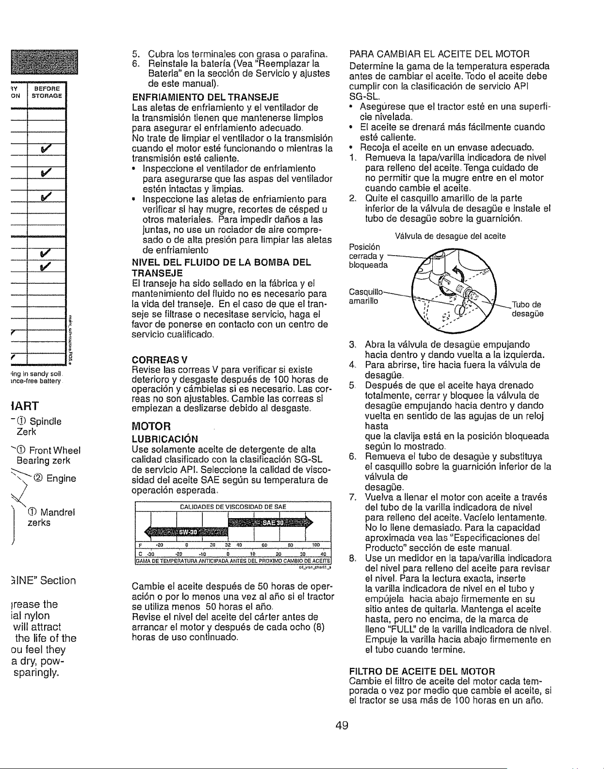
tART
-(2) Spindle
Zerk
"O Front Wheel
Bearing zerk
@ Engine
L%Mandrel
zerks
.NNE" Section
trease the
ial nylon
will attract
the life of the
ou feel they
a dry, pow-
sparingly,
5. Cubra los terminates con grasa o parafinao
6o Reinstale la baterfa (Yea "Reemplazar la
Bateria" en la secciSn de Servicio y ajustes
de este manual).
ENFRIAMIENTO DEL TRANSEJE
Las aletas de enfriamiento yel ventilador de
la transmisi6n tienen que mantenerse limpios
para asegurar el enfriamiento adecuado.
No trate de limpiar el ventilador o la transmisi6n
cuando el motor est_ funcionando o mientras la
transmisi6n est6 caliente.
•Inspeccfone el ventitador de enfriamiento
para asegurarse que las aspas del ventilador
est_n intactas y timpias.
, Inspeccione las atetas de enfriamiento para
verificar si hay mugre, recortes de c_sped u
otros materiales. Para impedir daRos alas
juntas, no use un rociador de aire compre-
sado o de alta presi6n para limpiar las aletas
de enfriamiento
NIVEL DEL FLUIDO DE LA BOMBA DEL
TRANSEJE
El transeje ha sido sellado en ta fb,brica y el
mantenimiento del fluido no es necesario para
la vida del transeje. En el caso de qua el tran-
seje se filtrase o necesitase servicio, haga el
favor de ponerse en contacto con un centro de
servicio cualificado,
CORREAS V
Revise las correas V para verificar si existe
deteriore y desgaste despots de 100 horas de
operaciSn y c_,mbielas si es necesario, Las cor-
reas no son ajustables,, Cambie las correas si
empiezan a deslizarse debido al desgaste,
MOTOR
LUBRICACION
Use solamente aceite de detergente de alta
calidad ctasificado con la clasificaci6n SG-SL
de servicio API. Seleccione la calidad de visco-
sidad del aceite SAE segt)n su temperatura de
o )eraci6n esperada.
CAUOADESDEV_SCOS_OADOESAE
1
_AMA D:E T E_,"tPERATUP_ ANT|C_FADA ANTES DEL PROXIMO CANBtO DE ACEITE
Cambie et aceite despu_s de 50 horas de oper-
aci6n o por Io menos una vez al a_o si el tractor
se utiliza menos 50 horas el aSo.
Revise el nivel del aceite del carter antes de
arrancar e! motor y despu_s de cada ocho (8)
horas de uso continuado.
PARA CAMBIAR EL ACEITE DEL MOTOR
Determine la garna de la temperatura esperada
antes de cambiar el aceiteo Todo e! aceite debe
cumplir con la ciasificaci6n de servicio AP1
SG-SL
• Aseg0rese qua el tractor est_ en una superfi-
cie nivelada,
•El aceite se drenar#, m&s f,_cilmente cuando
est_ calienteo
°Recoja el aceite en un envase adecuado,
1. Remueva la tapaJvarilla indicadora de nivel
para relleno del aceite. Tenga cuidado de
no permitir qua la mugre entre en et motor
cuando cambie el aceite.
2. Quite el casquitlo amarillo de ia parte
inferior de la v_.lvula de desagL)e e tnstale el
tubo de desagOe sobre la guarnici6n.
V&ivula de desag0e del aceite
Posici6n
cerraday _ _
bloqueada
Casquil!o_---.._.__
amarillo Tubo de
t desagi)e
3, Abra la v_.lvula de desagLJeempujando
hacia dentro y dando vuelta a la izquierda,
4. Para abrirse, tire hacia fuera la vb,fvula de
desagt3e,,
5, Despu_,s de que el aceite haya drenado
totalmente, cerrar y bloquee la vb,lvula de
desag0e empujando hacia dentro y dando
vueita en sentido de las agujas de un reloj
hasta
qua fa clavija est& en la posici6n bloqueada
segt]n Io mostrado_
6, Remueva el tubo de desagQe y substituya
el casquillo sobre la guarnici6n inferior de la
v#,lvula de
desag_)e.
7. Vuelva a Ilenar el motor con aceite a trav6s
del tubo de la varifla indicadora de nivel
para relleno del aceite, Vacfelo lentamente_
1'4oio Ilene demasiado_ Para la capaetdad
aproximada yea las "Especificaciones del
Producto" secci6n de este manuai_
8. Use un medidor en ta tapa/varilta indicadora
del nivel para reileno del aceite para revisar
el niveL Para la lectura exacta, inserte
la varilla indicadora de nivel en el tubo y
emp0jela hacia abajo firmemente en su
sitio antes de quitarlao Mantenga el aceite
hasta, pero no encima, de la marca de
Ileno "FULl2 de la varilla indicadora de nivel,
Empuje la varilla hacia abajo firmemente en
el tubo cuando termine.
F1LTRO DE ACEtTE DEL MOTOR
Cambie el filtro de aceite del motor cada tem-
porada ovez por medio que cambie el aceite, si
el tractor se usa mb.s de 100 horas en un aRo,.
49
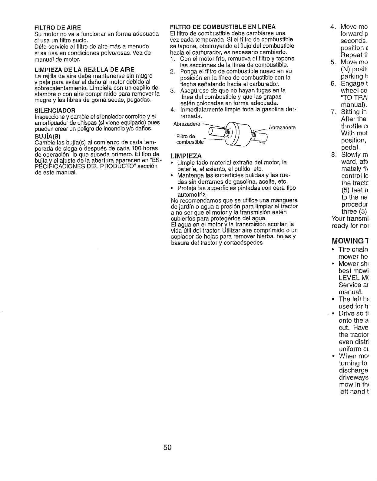
FILTRO DE AIRE
Su motor no vaa funcionar en forma adecuada
si usa un _tro sucioo
D61eservicio al filtro de aire m&s a menudo
si se usa en condiciones potvorosas, Vea de
manual de motor,
LtMPIEZA DE LA REJILLA DE AIRE
La rejilla de aire debe mantenerse sin mugre
y paja para evitar et dafio al motor debido al
sobrecatentamiento, Lfmpiela con un cepillo de
alambre o con aire comprimido para remover la
mugre y tas fibras de goma secas, pegadas.
StLENCtADOR
lnspeccione y cambie et silenciador corro[do y el
amortiguador de chispas (si viene equipado) pues
pueden crear un petigro de incendio yio daRos
BUJiA(S)
Cambie Ins bujfa(s) al comienzo de cada tem-
porada de siega o despu_s de cada 100 horns
de operaci6n, lo que suceda primero, El tipo de
buj[a y el ajuste de la abertura aparecen en "ES-
PECIFICACIONES DEL PRODUCTO" secci6n
de este manual,,
FILTRO DE COMBUSTIBLE EN LINEA
El filtro de combustible debe cambiarse una
vez cada temporada. Si el filtro de combustible
se tapona, obstruyendo el flujo del combustible
hacia et carburador, es necesario cambiarlo.
1. Con el motor fifo, remueva el fittro y tapone
Ins secciones de la ifnea de combustible°
2. Ponga et _tro de combustible nuevo en su
posici6n en la linen de combustible con la
flecha seSalando hacia el carburador.
3. Asegt)rese de que no hayan fugas en la
lfnea del combustible y que Ins grapas
est_n cotocadas en forma adecuada.
4. Inmediatamente fimpie toda la gasofina der-
ramada.
Abrazadera _-_ ,_F_-
combustible '___._-r_y
Abrazadera
LIMPIEZA
° Limpie todo material extra5o del motor, la
baterfa, el asiento, el pulido, etc.
•Mantenga Ins superficies pulidas y Ins rue-
das sin derrames de gasolina, aceite, etc_
•Proteja Ins superficies pintadas con cera tipo
automotriz.
No recomendamos que se utilice una manguera
de jardfn o agua a presi6n para limpiar el tractor
a no ser que el motor y la transmisi6n est_n
cubiertos para protegerlos del agu&
El agua en el motor y la transmisi6n acortan la
vida 0til det tractor. Utilizar aire comprimido o un
soplador de hojas para remover hierba, hojas y
basura del tractor y cortac6spedes
4, Move mo
forward p
seconds°
position E
Repeat tt'
5. Move mo
(N) positi
parking b
6_ Engage t
wheel co
"TO TRA_
manual).
7. Sitting in
After the
throttle cl
With mot
position,
pedal.
8_ Slowly m
ward, aftt
mately fi\
control le
the tractc
(5) feet re
to the ne
procedur
three (3)
Your transmi
ready for nol
MOWING'I
-Tire chain
mower ho
° Mower sh{
best mowi
LEVEL M(
Service at
manual,
• The left h_
used for tr
• Drive so tl
onto the a
cut. Have
the tractor
even distri
uniform c[
° When mo,
turning to
discharge
driveways
mow in th_
left hand t
5O
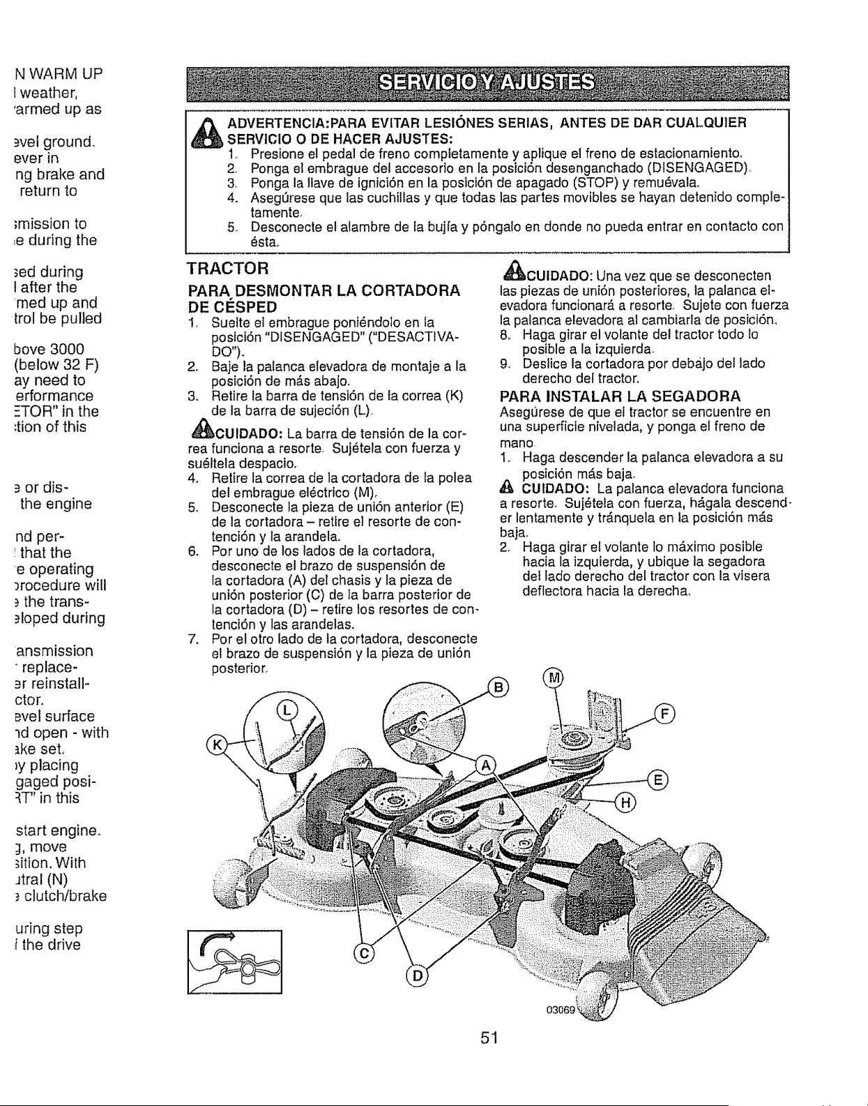
N WARM UP
! weather,
'armed up as
wel ground.
ever in
ng brake and
return to
}mission to
,e during the
_ed during
I after the
rned up and
trol be pulled
bove 3000
(below 32 F)
ay need to
erformance
=TOR" in the
;tion of this
_=or dis-
the engine
nd per-
that the
e operating
3rocedure will
the trans-
.=loped during
ansmission
replace-
ar reinstall-
ctor.
_vet surface
ld open - with
_ke set,
ly placing
gaged posi-
:{T" in this
_DVERTENCIA:PARA EVITAR LESIONES SERIAS, ANTES DE DAR CUALQUlER
SERVICIO O DE HACER AJUSTES:
1., Presione el pedal de freno completamente y aptique el freno de estacionamientoo
2, Ponga el embrague del accesorio en la postci6n desenganchado (DISENGAGED).
3, Ponga la llave de ignici6n en la posici6n de apagado (STOP) y remu6vala.
4. Aseg_rese que las cuchillas y que todas las partes movibles se hayan detenido comple-
tamente,
5. Desconecte el atambre de la bujfa y p6ngalo en donde no pueda entrar en contacto con
6stao
TRACTOR
PARA DESMONTAR LA CORTADORA
DE ClaSPED
I, Suelte el embrague poni_ndolo en la
poslci6n "DISENGAGED" ("DESACTtVA-
DO")_
2. Baje la palanca elevadora de montaje a la
posici6n de m_,s abajo,,
3o Retire la barra de tensi6n de la correa (K)
de la barra de sujeci6n (L),
_CUIDADO: La barra de tensi6n de la cor-
rea funciona a resorte. Suj_tela con fuerza y
su_ltela despacio.
4. Retire la correa de la cortadora de la polea
del embrague el_ctrico (M),
5,, Desconecte la pieza de uni6n anterior (E)
de la cortadora - retire el resorte de con-
tenci6n y la arandelao
6. Por uno de los lados de la cortadora,
desconecte el brazo de suspensi6n de
la cortadora (A) del chasis y la pieza de
uni6n posterior (C) de ]a barra posterior de
la cortadora (D) - retire los resortes de con-
tenci6n y las arandelas.
7. Por el otro lado de la cortadora, desconecte
el braze de suspensi6n y la pieza de uni6n
posterior.
_!tJCUIDADO: Una vez que se desconecten
las piezas de uni6n posteriores, la palanca et-
evadora funcionar& a resorte Sujete con fuerza
la palanca elevadora al cambiarla de posici6no
8o Haga girar el volante del tractor todo Io
posible a la izquierda_
9. Deslice la cortadora por debajo del lado
derecho del tractor.
PARA INSTALAR LA SEGADORA
Asegurese de que el tractor se encuentre en
una superficle nivelada, y ponga el freno de
mano
I,_ Haga descender la palanca elevadora a su
posici6n m_s baja_
,_ CUIDADO: La palanca elevadora funciona
a resorte. Suj6tela con fuerza, hAgala descend-
er lentamente y tr_nquela en la posici6n m,_s
bajao
2. Haga girar el volante lo m_ximo posible
hacia la izquierda, y ubique la segadora
det lado derecho del tractor con la visera
deffectora hacia la derecha,.
start engine°
_1,move
_ition. With
Jtral (N)
_.clutch/brake
uring step
i the drive
03069 _
51
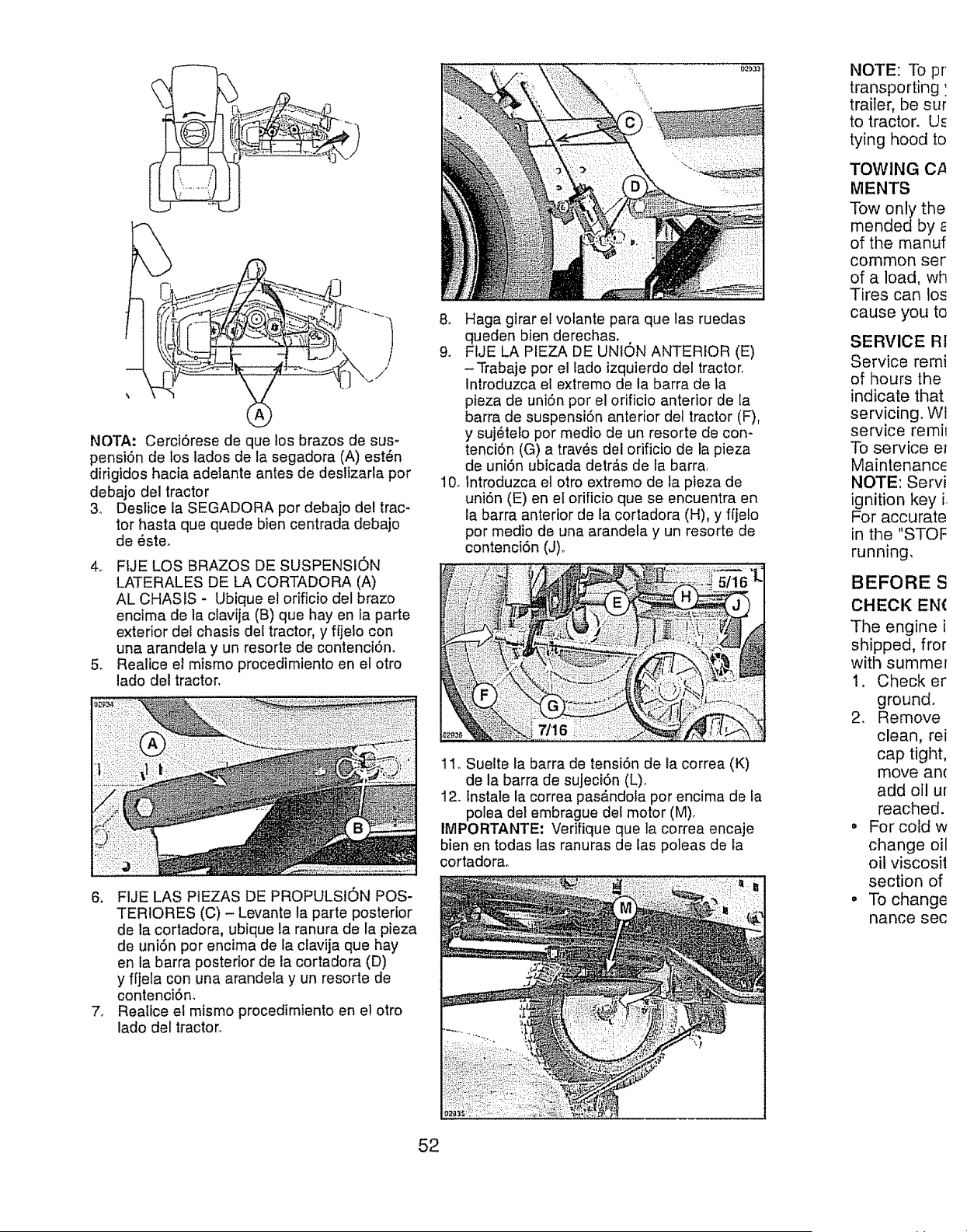
NOTA: Cerct6rese de que los brazos de sus-
pensi6n de los lados de la segadora (A) est6n
dirigidos hacia adelante antes de deslizarla por
debajo del tractor
3. Deslice la SEGADORA por debajo del trac-
tor hasta que quede bien centrada debajo
de _ste_
4o FIJE LOS BRAZOS DE SUSPENSION
LATERALES DE LA CORTADORA (A)
AL CHASIS - Ubique et orificio del brazo
encima de la clavija (B) que hay en la parte
exterior del chasis del tractor, y fljelo con
una arandela y un resorte de contenci6n.
5. Realice el mismo procedirniento en el otto
lado del tractor.
6. FIJE LAS PIEZAS DE PROPULSION POS-
TERIORES (C) - Levante la parte posterior
de la cortadora, ubique la ranura de la pieza
de uni6n per encima de la clavija que hay
en la barra posterior de la cortadora (D)
y f[jela con una arandela y un resorte de
contenci6n,
7. Realice e! mismo procedimiento en el otro
lado del tractor°
& Haga girar el volante para que las ruedas
queden bien derechas.
9_ FIJE LA PIEZA DE UNION ANTERIOR (E)
-Trabaje por el lado izquierdo del tractor.
Introduzca el extremo de la barra de fa
pieza de uni6n por el orificio anterior de la
barra de suspensi6n anterior del tractor (F),
y suj_telo por medio de un resorte de con-
tenci6n (G) a tray, s del orificio de la pieza
de uni6n ubicada detr_.s de la barra.
10_lntroduzca et otro extremo de la pieza de
uni6n (E) en et orificio que se encuentra en
la barra anterior de la cortadora (H), y f[jelo
por medio de una arandela y un resorte de
contenci6n (J)o
11o Suelte la barra de tensi6n de la correa (K)
de la barra de sujeci6n (L)o
12_ tnstale la correa pas&ndola por encima de la
polea del embrague del motor (M)_
IMPORTANTE: Verifique que la correa encaje
bienen todas las ranuras de las poleas de la
cortadorao
NOTE: To pr
transporting'.
trailer, be sur
to tractor. Us
tying hood to
TOWING C/_
MENTS
Tow only the
mended by
of the manuf
common ser
of a load, wh
Tires can los
cause you to
SERVICE RI
Service remi
of hours the
indicate that
servicing. Wi
service retail
To service el
Maintenance
NOTE: Servi
ignition key i
For accurate
in the "STOF
running,
BEFORE S
CHECK EN(
The engine i
shipped, fror
with summe_
1. Check er
ground°
2, Remove
clean, rei
cap tight,
move an(
add oil ur
reached.
• For cold w
change oil
oilviscosi!
section of
• To change
nance sec
52
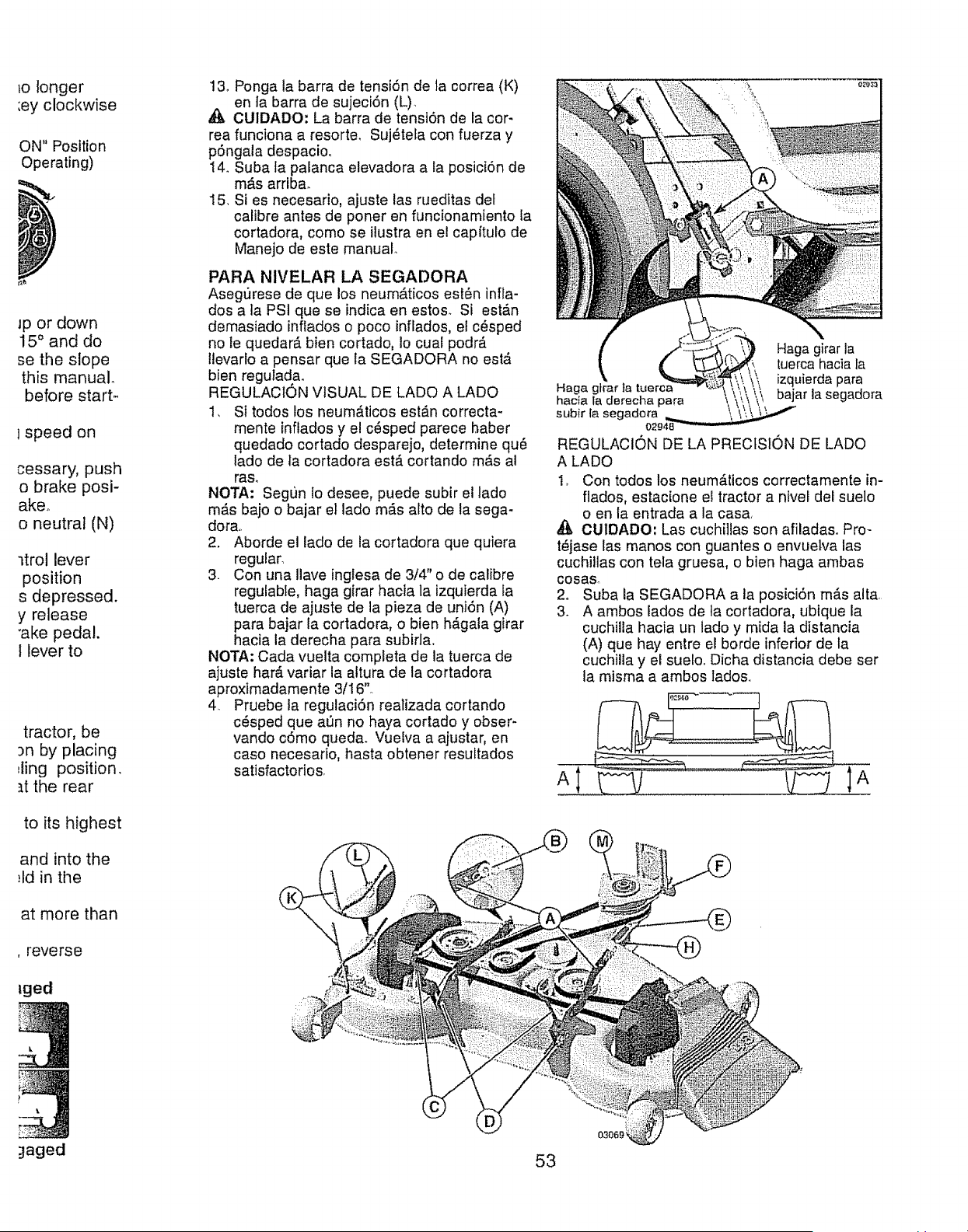
_o longer
:ey clockwise
ON" Position
Operating)
Jp or down
15 ° and do
se the slope
this manual°
before start-
lspeed on
cessary, push
o brake posi-
akeo
o neutral (N)
ltrol lever
position
s depressed.
y release
"ake pedal.
I lever to
tractor, be
3n by placing
Jing position,
_t the rear
to its highest
and into the
:ld in the
at more than
, reverse
lged
_aged
13o Ponga ta barra de tensi6n de ta correa (K)
en la barra de sujeci6n (L).
,_ CUIDADO: La barra de tension de la cor-
rea funciona a resorte. Suj_tela con fuerza y
p6ngala despacio,
14oSuba fa palanca elevadora a la posici6n de
m#,s arriba.
15. Si es necesario, ajuste las rueditas det
calibre antes de porter en funcionamiento la
cortadora, como se ilustra en el cap(tulo de
Manejo de este manual.
PARA NIVELAR LA SEGADORA
Asegurese de que los neum,_ticos esl#n infla-
dos a ]a PSI que se indica en estos. Si est,_n
demasiado inflados o poco inflados, el c_sped
no le quedar_, bien cortado, Io cual podr_.
llevarlo a pensar que la SEGADORA no est&
bien regulada.
REGULACION VISUAL DE LADO A LADO
1, Si todos los neum_.ticos est_n correcta-
mente inftados y el c6sped parece haber
quedado cortado desparejo, determine qu_
lado de la cortadora est,. cortando m_,s al
raso
NOTA: Segun Io desee, puede subir el lado
m_s bajo o bajar el lado m_s alto de la sega-
dora,.
2. Aborde el lado de la cortadora que quiera
regular.
3. Con una Ilave inglesa de 3/4' o de calibre
regulable, haga girar hacia la izquierda fa
tuerca de ajuste de la pieza de uniSn (A)
para bajar la cortadora, o bien h_gala girar
hacia la derecha para subirla.
NOTA: Cada vuelta completa de la tuerca de
ajuste har_. variar la altura de la cortadora
aproxtmadamente 3Ii 6"°
4. Pruebe la regulaci6n realizada cortando
c_,sped que aen no haya cortado y obser-
vando cOmo queda. Vuelva a ajustar, en
caso necesario, hasta obtener resultados
satisfactorios
Haga girar la
tuerca hacia la
Haga gtrar la tuer izquierda para
hacia la derecha para \ bajar la segadora
subir [a segadora
o2
REGULACION DE LA PRECISION DE LADO
A LADO
1_ Con todos los neumAticos correctamente in-
flados, estacione el tractor a nivel del suelo
o en la entrada a la casa
CU1DADO: Las cuchiilas son afiladaso Pro-
t_jase las manos con guantes o envuelva las
cuchillas con tela gruesa, o bien haga ambas
cosa&
2o Suba la SEGADORA a la posici6n m_.s alta.
3. A ambos lados de la cortadora, ubique la
cuchiUa hacia un lado y mida la distancia
(A) que hay entre el borde inferior de la
cuchilla y el suelo. Dicha distancia debe ser
]a misma a ambos lados..
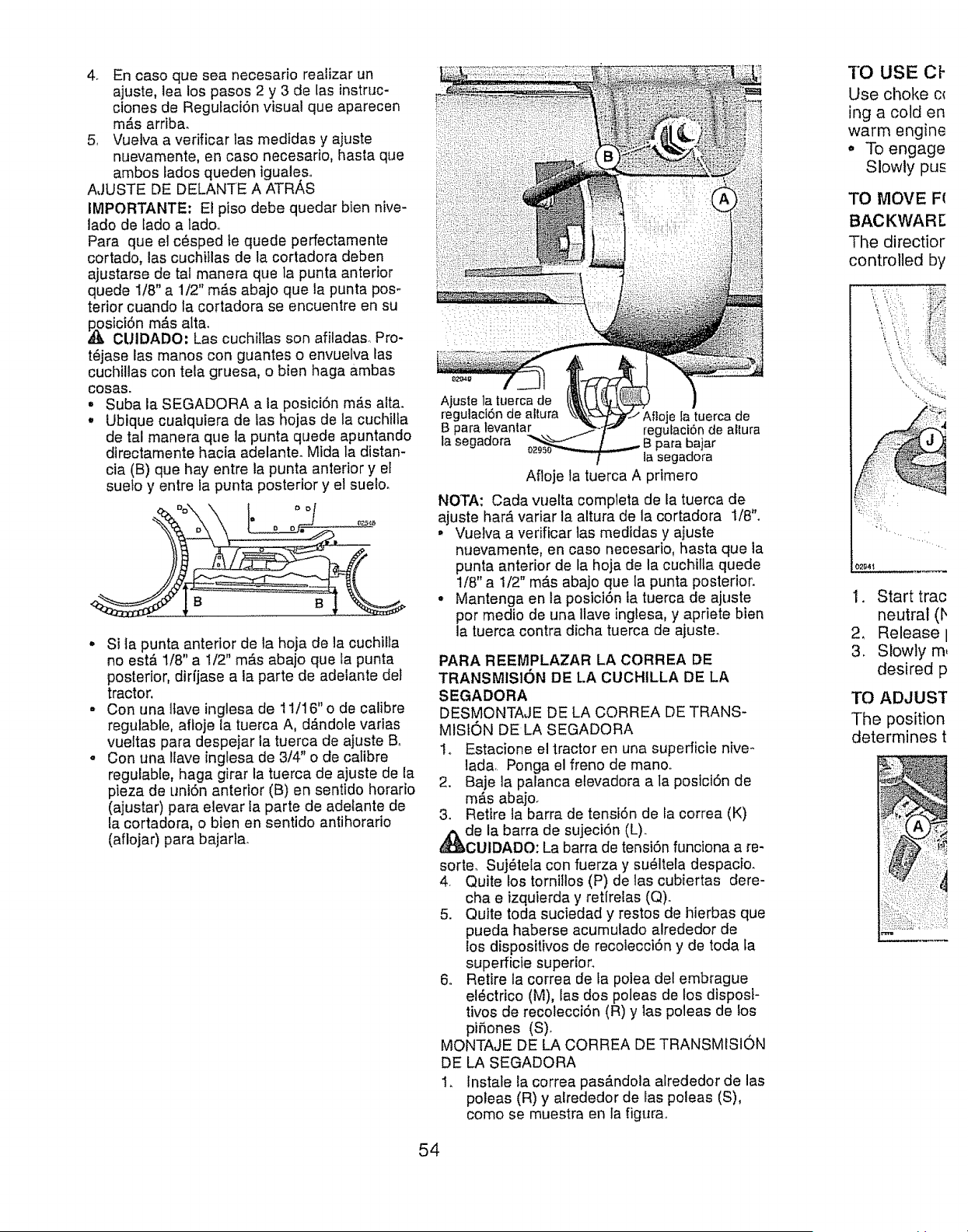
4o Encasoqueseanecesarioreafizarun
ajuste,lealospasos2y 3de lasinstruc-
clonesde Regufaci6nvisualqueaparecen
m,_sarriba.
5, Vuelvaa verificarlasmedidasy ajuste
nuevamente,encasonecesario,basraque
ambostadosquedenigualeso
AJUSTEDEDELANTEAATRAS
IMPORTANTE:Elpisodebequedarblennive-
ladodeladoatado..
Paraqueelc_spedtequedeperfectamente
cortado,lascuchi!lasdelacortadoradeben
ajustarsedetalmaneraquela puntaanterior
quede1/8"a1t2"m_.sabajoquelapuntapos-
teriorcuandola cortadoraseencuentreensu
,_sicidn m_s altar
CUIDADO: Las cuchillas son afiladas_ Pro-
t6jase las manos con guantes o envuefva las
cuchillas con tela gruesa, o bien haga ambas
cosas.
•Suba la SEGADORA a la posici6n m_s alta.
•Ubtque cualquiera de las hojas de la cuchilta
de tal manera que la punta quede apuntando
dtrectamente hacia adelante. Mtda la distan-
cia (B) que hay entre la punta anterior y el
sueto y entre ia punta posterior y el suetoo
° Si la punta anterior de la hoja de la cuchilla
no estb, 1/8" a 1/2" m_s abajo que ta punta
posterior, dirfjase a la parte de adelante del
tractor.
•Con una llave inglesa de 11/16"o de calibre
regulable, affoje la tuerca A, d,_ndole varias
vueltas para despejar ia tuerca de ajuste B.
• Con una iiave ingtesa de 3!4" o de calibre
regulable, haga girar la tuerca de ajuste de la
pieza de uni6n anterior (B) en sentido horario
(ajustar) para eievar la parte de adelante de
la cortadora, o bienen sentido antihorario
(aflojar) para bajarta_
A}usIe la tuerca de
regulaci6n de altura la tuerca de
B para levantar regufaci6n de altura
ta segadora para bajar
la segadora
Afloje la tuerca A primero
NOTA: Cada vuelta completa de la tuerca de
ajuste har,_variar la altura de la cortadora 1/8".
• Vuelva a verificar las medidas y ajuste
nuevamente, en caso necesario, hasta que la
punta anterior de la hoja de la cuchilla quede
1/8" a 1/2" m_,s abajo que la punta posterior.
° Mantenga en la posici6n la tuerca de ajuste
por medic de una Ilave inglesa, y apriete bien
la tuerca contra dicha tuerca de ajuste.
PARA REEMPLAZAR LA CORREA DE
TRANSMISION DE LA CUCHILLA DE LA
SEGADORA
DESMONTAJE DE LA CORREA DE TRANS-
MISt0N DE LA SEGADORA
1o Estacione el tractor en una superficie hive *
ladar Ponga el freno de manoo
2. Baje la palanca etevadora a la posici6n de
m_.s abajo_
3. Retire la barra de tensi6n de la correa (K)
de la barra de sujeci6n (L).
CUIDADO: La barra de tensiSn funciona a re-
sorteo Suj_tela con fuerza y su_ltela despacio.
4. Quite los tornitlos (P) de las cubiertas dere-
cha e izquierda y retfrelas (Q).
5. Quite toda suciedad y restos de hierbas que
pueda haberse acumulado alrededor de
los dispositivos de recolecci6n y de toda ta
superficie superior.
6. Retire la correa de la polea del embrague
el6ctrico (M), las dos poleas de los dispost-
tivos de recolecci6n (R) y las poleas de los
piSones (S).
MONTAJE DE LA CORREA DE TRANSMISION
DE LA SEGADORA
1. Instale la correa pas_.ndola alrededor de las
poleas (R) y alrededor de las poleas (S),
como se muestra en la figura_
TO USE Ct-
Use choke ct
ing a cold en
warm engine
,, To engage
Slowly pus
TO MOVE F(
BAC KWAR E
The directior
controlled by
,; .i :! _,_._
4
02_4_
1. Start trac
neutral (b
2_ Release I
3. Slowly m,
desired p
TO ADJUST
The position
determines t
54
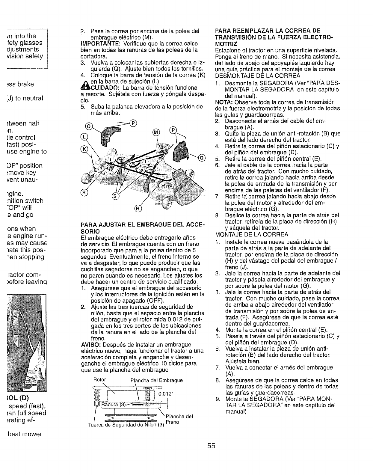
m into the
fety glasses
djustments
vision safety
_ss brake
iJ) to neutral
,_tween half
bn.
lie control
fast) posi-
use engine to
OP" position
_move key
vent unau _
tgine.
nition switch
OP" will
;e and go
ons when
,e engine run-
es may cause
late this pos-
len stopping
ractor com-
)efore leaving
(D)
speed (fast).
fan full speed
,'rating ef-
best mower
2. Pase la correa por encima de la polea del
embrague ef_ctrico (M)_
IMPORTANTE: Verifique que la correa calce
bienen todas las ranuras de las poleas de la
cortadora.
3, Vuelva a colocar tas cubiertas derecha e iz-
quierda (Q). Ajuste bien lodos los tornillos,
4. Coloque ia barra de tensi6n de la correa (K)
en la barra de sujeciOn (L).
CU1DADO: La barra de tensi6n funciona
a resorte. Suj_teta con fuerza y p6ngala despa-
cio,
5, Suba ia palanca elevadora a la posici6n de
m#.s arriba.
®
PARA AJUSTAR EL EMBRAGUE DEL ACCE-
SORIO
El embrague el_ctrtco debe entregade a5os
de servicio. El embrague cuenta con un freno
incorporado que para a la polea dentro de 5
segundos. Eventualmente, el freno interno se
va a desgastar, Io que puede producir que las
cuchillas segadoras no se enganchen, e que
no paren cuando es necesario. Los ajustes los
debe hacer un centro de servicio cuatificado.
1. Asegt_rese que el embrague del accesorio
y los interruptores de Ia igntci6n est6n en la
posici6n de apagado (OFF).
2_ Ajuste las tres tuercas de seguridad de
nil6n, hasta que el espacio entre la ptancha
del embrague y el rotor mida 0,012 de pul-
gada en los tres cortes de las ubicaciones
de la ranura en el lado de la plancha del
freno.
AVISO; Despu_s de instalar un embrague
el_ctrico nuevo, haga funcionar el tractor a una
aceleraci6n completa y enganche y desem
ganche el embrague el_ctrico 10 ciclos para
que use la plancha del embrague.
Rolor Planchadel Embrague
012"
Tuerca_e-S'e_lur_-Niion (3)
PARA REEMPLAZAR LA CORREA DE
TRANSMISION DE LA FUERZA ELECTRO-
MOTRIZ
Estacione el tractor en una superficie nivelada,
Ponga el freno de manoo Si necesita asistencia,
del lado de abajo del apoyapi_s tzquierdo hay
una gufa pr#.ctica para el montaje de ta correa
DESMONTAJE DE LA CORREA
1, Desmonte la SEGADORA (Ver"PARA DES-
MONTAR LA SEGADORA en este capffulo
del manual).
NOTA: Observe toda la correa de transmisi6n
de la fuerza electromotriz y la posici6n de todas
las gufas y guardacorreas.
2, Desconecte el arn6s del cable del em-
brague (A).
3o Quite la pieza de uni6n anti-rotaci6n (B) que
est,. del lado derecho del tractor,
4. Retire la correa del piff,On estacionario (C) y
del pi56n del embrague (D).
& Retire la correa del pifiOn central (E).
6. Jale el cable de la correa hacia ia parle
de arras del tractor. Con mucho cufdado,
retire la correa jalando hacla arriba desde
la polea de entrada de la transmisiOn y por
encima de las patetas det ventilador (F)..
7, Retire la_correa jalando hacia abajo desde
la polea del motor y alrededor del em-
brague el_ctrico (G),
& Deslice la correa hacia la parte de atr_,s del
tractor, retffela de la placa de direcci6n (H)
y s_quela del tractor°
MONTAJE DE LA CORREA
1. lnstale la correa nueva pas&ndota de la
parte de atr_.s a la parte de adelante del
tractor, por encima de la placa de direcci6n
(H) y del v_stago del pedal del embrague /
freno (J),
2. Jale la correa hacia la parte de adetante det
tractor y p&sela alrededor del embrague y
por sobre la polea del motor (G).
3. Jafe la correa hacia la parte de atr_.s del
tractor. Con mucho cuidado, pase la correa
de arriba a abajo alrededor del ventilador
de transmisi6n y por sobre la polea de en-
trada (F). Asegerese de que la correa est_
dentro del guardacorrea.
4o Monte ta correa en el pi56n central (E).
5.. Pb.sela a travOs del pi56n estacionario (C) y
det pi56n del embrague (D)o
& Vuelva a instalar ia pieza de uni6n anti-
rotaci6n (B) de! iado derecho del tractor°
Aj_stela bieno
7_ Vuelva a conectar el arn6s del embrague
(A)o
8. Asegurese de que la correa calce en todas
las ranuras de las poteas y dentro de todas
las gufas y guardacorreas,
9. Monte fa SEGADORA (Ver"PARA MON-
TAR LA SEGADORA" en este capitulo del
manual),
55
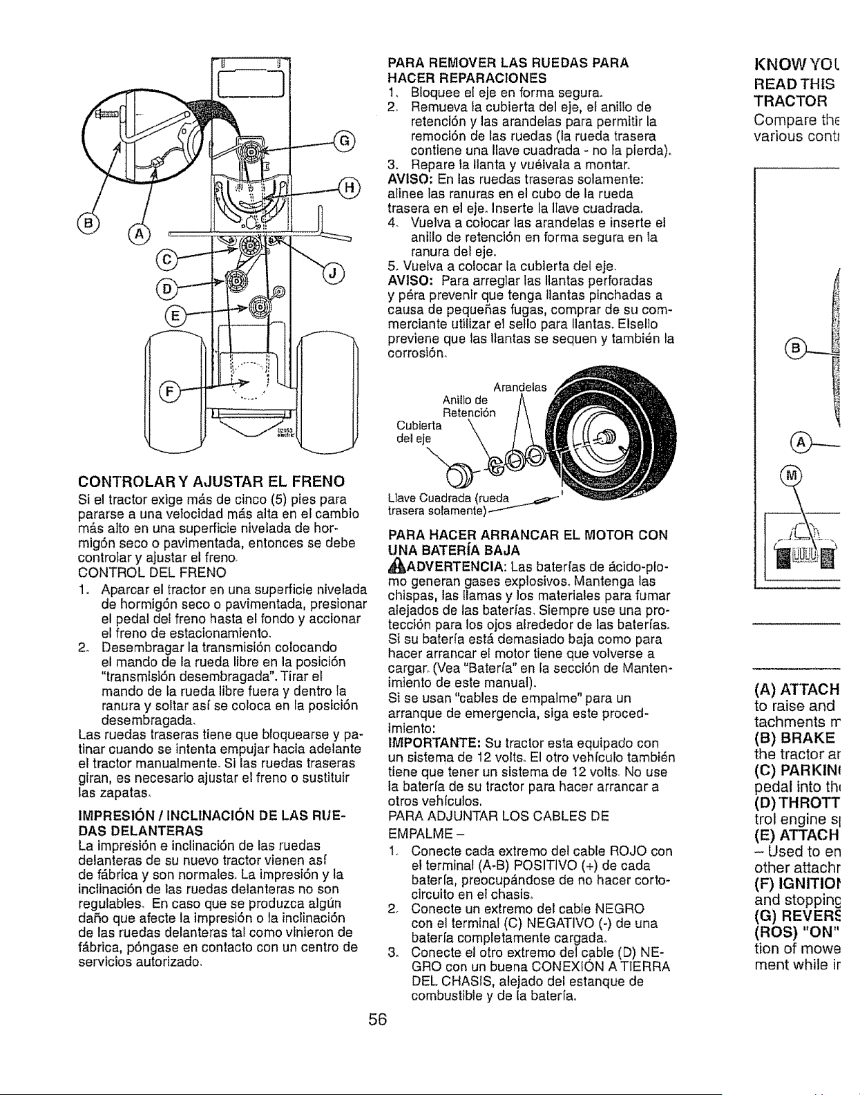
CONTROLAR Y AJUSTAR EL FRENO
Si el tractor exige m,_s de cinco (5) pies para
pararse a una vetocidad m_s alta en el cambio
m_s atto en una superficie nivelada de hor-
mig6n seco o pavimentada, entonces se debe
controlar y ajustar el freno_
CONTROL DEL FRENO
1. Aparcar el tractor en una superficie nivelada
de hormig6n seco o pavimentada, presionar
el pedal del freno hasta el fondo y accionar
el freno de estacionamiento.
2o Desembragar la transmisi6n colocando
el mando de la rueda libre en la posici6n
"transmlst6n desembragada". Tirar et
mando de la rueda libre fuera y dentro la
ranura y soltar as( se cotoca en la postciSn
desembragada.
Las ruedas traseras tiene que bloquearse y pa-
tinar cuando se intenta empujar hacia adelante
el tractor manualmente. SI las ruedas traseras
giran, es necesario ajustar el freno o sustituir
las zapatas,
IMPRESlON 1INCL1NACION DE LAS RUE-
DAS DELANTERAS
La impresiOn e inclinaciSn de las ruedas
delanteras de su nuevo tractor vienen asf
de f_brica y son normaleso La impresi6n y la
inctinaci6n de las ruedas delanteras no son
regutables. En caso que se produzca algun
da5o que afecte la impresi6n o la inclinaci6n
de las ruedas delanteras tal como vfnieron de
f_brica, pSngase en contacto con un centro de
servtcios autorizado.
PARA REMOVER LAS RUEDAS PARA
HACER REPARACIONES
1. Bloquee el eje en forma segura.
2° Remueva la cubierta del eje, el aniiio de
retenci6n y las arandelas para permitir la
remoci6n de las ruedas (la rueda trasera
contiene una Ilave cuadrada - no la pierda).
3. Repare la Ilanta y vu6tvala a montar.
AVtSO: En las ruedas traseras solamente:
alinee las ranuras en el cubo de la rueda
trasera en el eje. Inserte la Ilave cuadrada.
4. Vuelva a cotocar las arandelas e inserte e!
anillo de retenciOn en forma segura en la
ranura del eje..
5. Vuelva a colocar la cubierta del eje.
AVtSO: Para arreglar las Ilantas perforadas
y p_ra preventr que tenga Ilantas pinchadas a
causa de peque5as fugas, comprar de su com-
merciante utilizar el seflo para Ilantaso Elselio
previene que las ltantas se sequen y tambi_n la
corrosion°
Arandelas
Anillo de
Retenci6n
Cubierta
del eje
Ltave Cuadrada (rueda _
trasera solamente)
56
PARA HACER ARRANCAR EL MOTOR CON
UNA BATER|A BAJA
_,),ADVERTENClA: Las baterfas de _cido-plo-
mo generan gases explosivos. Mantenga las
chispas, las llamas y los materiales para fumar
alejados de las baterfas. Siempre use una pro-
tecciSn para los ojos alrededor de las bater[as.
Si su baterfa est_ demasiado baja como para
hacer arrancar el motor tiene que volverse a
cargar_.(Vea "Baterfa" en fa secci6n de Manten-
irniento de este manual).
Si se usan "cables de empatme" para un
arranque de emergencia, siga este proced-
lmiento:
1MPORTANTE: Su tractor esta equipado con
un sistema de 12 volts° El otto veh[culo tambi_n
tiene que tener un sistema de 12 volts. No use
la bater[a de su tractor para hacer arrancar a
otros vehiculos,
PARA ADJUNTAR LOS CABLES DE
EMPALME -
Io Conecte cada extremo del cable ROJO con
el terminal (A-B) POSITIVO (+) de carla
bater[a, preocup_ndose de no hacer corto-
circuito en e! chasis_
2o Conecte un extremo del cable NEGRO
con el terminal (C) NEGATlVO (-) de una
bater[a completamente cargad&
3_ Conecte el otro extremo del cable (D) NE-
GRO con un buena CONEXION A TIERRA
DEL CHASIS, alejado del estanque de
combustible y de la baterfa.
KNOW YO L
READ THIS
TRACTOR
Compare th_
various contt
(A) ATTACH
to raiseand
tachments rr
(B) BRAKE
the tractor ar
(C) PARKINt
pedal into th_
(D) THROTT
trol engine Sl
(E) ATTACH
- Used to en
other attachr
(F) IGNITIOI'
and stoppinc
(G) REVER_
(ROS) "ON"
tion of mowe
ment while ir
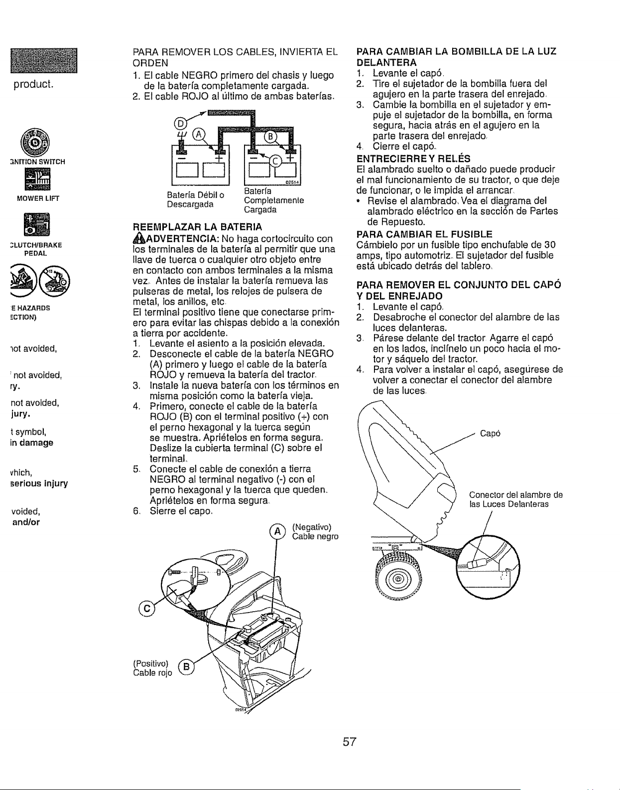
product.
3NITION SW_CH
MOWER LIFT
3LUTCH/BRAKE
PEDAL
E HAZARDS
=CTION)
motavoided,
not avoided,
ry.
not avoided,
jury.
tsymbol,
in damage
vhich,
serious injury
voided,
andlor
PARA REMOVER LOS CABLES, INVIERTA EL
ORDEN
I,. El cable NEGRO prirnero del chasis y luego
de la baterfa completamente cargada,.
2. El cable ROJO al t]ltimo de ambas batedas.
Bateria D_bil o Baterfa
Descargada Completamente
Cargada
REEMPLAZAR LA BATERIA
_I_ADVERTENCIA: No haga cortocircuito con
los terminales de la baterfa al permitir que una
llave de tuerca o cualquier otto objeto entre
en contacto con ambos terminales a la misma
vez_ Antes de instaiar la bater[a remueva las
pulseras de metal, los relojes de pulsera de
metal, los anillos, etc.
El terminal positivo tiene que conectarse prim-
ero pare evitar las chispas debido ala conexi6n
a tierra por accidente.
1. Levante el asiento ala posici6n elevada.
2. Desconecte el cable de ta baterla NEGRO
(A) primero y luego et cable de la bater[a
ROJO y remueva la baterfa deI tractor.
3, Instale la nueva baterfa con los tdrminos en
misma posici6n como la bateda vieja.
4. Primero, conecte el cable de la bateria
ROJO (B) con el terminal positivo (+) con
el perno hexagonal y la tuerca seg_n
se muestra. Apri_telos en forma segurao
Deslize la cubierta terminal (C) sobre el
terminal
5. Conecte el cable de conexi6n a tierra
NEGRO at terminal negativo (-) con et
perno hexagonal y la tuerca que queden,.
Apri_telos en forma segura.,
6_ Sierre et capo.
_-') (Nega|ivo)
Cable negro
(Positivo)
Cable rojo ._"
PARA CAMBIAR LA BOMBILLA DE LA LUZ
DELANTERA
1. Levante el cap6.
2. Tire et sujetador de la bombilta fuera del
agujero en la parte trasera del enrejado,
3. Cambie la bombilla en el sujetador y em-
puje el sujetador de la bombilla, en forma
segura, hacia atr&s en el agujero en la
parte trasera del enrejadoo
4. Cierre el cap6o
ENTREClERREY RELI_S
El alambrado suelto o da5ado puede producir
el mal funcionamiento de su tractor, o que deje
de funcionar, o le impida el arrancar,
• Revise el alambrado. Vea el diagrama del
alambrado el_ctrico en la secci6n de Partes
de Repuesto.
PARA CAMBtAR EL FUSIBLE
C#,mbielo pot un fusible tipo enchufable de 30
amps, tipo automotriz. El sujetador del fusible
est#t ubicado detr&s del tablero,.
PARA REMOVER EL CONJUNTO DEL CAPO
YDEL ENREJADO
1. Levante el cap6.
2. Desabroche el conector del alambre de las
luces delanteras.
3 P#,rese delante del tractor_ Agarre el cap6
en los lados, incl[nelo un poco hacia el mo-
tor y s_,quelo def tractor.
4. Pare volver a instalar el cap6, asegurese de
volver a conectar el conector del alambre
de las luces.
Cap6
Conector del alambre de
las Luces Delan[eras
57
MOTOR
PARA AJUSTAR EL CABLE DE CONTROL
DE LA ACELERACION
El control de la aceleraci6n ha sido preajustado
en ia f,_brica y no deberfa necesitar ajustes..
Revise los ajustes que se describen a continu-
aci6n, antes de soltar el cable° Si el ajuste es
necesario, vea de manual de motor,
El control de la aceleraci6n ha sido preajustado
en la f#,brica y no deberia necesitar ajustes. Si
el ajuste es necesario, vea de manual de motor.
PARA AJUSTAR EL CONTROL DE LA ES-
TRANGULACION
El control de la estrangulaci6n ha sido
preajustado en la f_brica y no deberfa necesitar
ajustes. Si el ajuste es necesario, vea de
manual de motor_
PARA AJUSTAR EL CARBURADOR
El carburador ha sido preajustado en fa f,_brica
y no deberfa necesitar ajustes. Sin embargo, se
pueden necesitar ajustes de menor importan-
cia para compensar por las diferencias en el
combustible, temperatura, altura o carga. Si et
carburador necesita ajustes, yea de manual de
motor.
4o Roll tract
5, Remove
shield up
TO DRIVE
(See Open
and functi_
1o Be sure
have bee
2_ Check er
with gas(
3_ Place fre
mission
TRANSP
this man_
4. Sit on se
depress,
parking
5. Place mc
(N) positi
6. Raise att
position.
7. Remove
engine (s
the Oper
After en£
control tc
8o Release
9o Slowly m
forward
skid.
1&Apply br_
brake an,
neutral p
11 .Turn ignil
Continue wil
CHECKT!If
The tires on
at the facton
rect tire pres
cuttingperfo
•Reduce tit
tires.
CHECK DE
For best cutl
ing should b
LEVEL MOV
Adjustments
CHECK FC
OF ALL BE
See the figu_
ing motion a
in the Servic
of this manu
routed corre
58
fnmediatamente prepare su tractor para el
almacenamiento al final de la temporada o si el
tractor no se va a usar por 30 dfas o m&so
_I_ADVERTENCIA: Nunca almacene el trac-
tor con gasolina en el estanque dentro de un
edificio en donde los gases pueden alcanzar
una llama expuesta o una chispao Permita que
el motor se enfrfe antes de almacenarlo en
cualquier recinto privador
TRACTOR
Cuando el tractor se va a almacenar pot cierto
perfodo de tiempo, tlmpiela cuidadosamente,
quite toda la mugre, la grasa, las hojas, etc.
Gu#trdela en una _rea limpia y seca,
1. Limpie todo el tractor (vea "LtMPIEZA" en la
secciSn de Mantenimiento en este manual)°
2. Inspeccione y cambie las correas, si es
necesario (yea las instrucciones para el
cambio de las correas en la secciSn de
Servicio y Ajustes de este manual).
3, Lubrfquelo, segQn se muestra en la secci6n
de Mantenimiento de este manual.
4. Asegdrese que todas las tuercas, los
pernos y los tornillos est_n sujetados
en forma segura. Inspeccione las partes
movibles para vedficar si hay dafio, rotura o
desgaste. C_mbielas si es necesario.
5, Retoque todas superficies pintadas oxida-
das o picadas; aplique lija antes de pintar.
BATER{A
. Cargue la bater{a completamente antes de
guardarla.
• Despu6s de cierto perfodo de tiempo en
almacenamiento, la bater[a puede necesitar
vo[ver a cargarse.
• Para ayudar a evitar la corrosiSn y las fugas
de potencia durante largos perfodos de
almacenamiento, se deben desconectar
ios cables de la bater_a y se debe limpiar
cuidadosamente (vea "PARA L]MPtAR LA
BATER[A Y LOS TERMINALES" en la sec-
ciSn de Mantenimientode este manual),
. Despu6s de limpiarta, deje los cables desco-
nectados y p6ngalos en donde no puedan
entrar en contacto con los terminales de la
baterfa
° St se remueve la baterfa del tractor para el
almacenamiento, no la guarde directamente
sobre concreto o sobre superficies h_medaso
MOTOR
SISTEMA DE COMBUSTIBLE
IMPORTANTE: Es important evitar que se
forman deposltos de goma en partes funda-
mentales del sistema de combus-tible tales
como el carburador, el fiitro del combustible,
la manguera del combustibles mezclados con
alcohol (conocido como gasohol o que tienen
etanot o metanol) pueden atraer humedad, fo
ue conduce a la separaciSn y a la formaci6n
e acudos durante elalmacenamientoo La
gasolina acidica puede daRar el sistema de
combustible de un motor durante el periodo de
almacenamiento.
o Vaciar el dep6sito del carburante poniendo
en marcha el motor y dej_.ndolo funcionar
hasta que el carburante termine el carbura-
dor est6 vac[oo
* Nunca use los productos para limpieza de]
carburador o del motor en el estanque de
combustible pues se pueden producir daSos
permanentes.
° Use combustible nuevo la pr6xima
temporada.
AVISO: El estabilizador de combustible es una
alternativa aceptable para reducir a un mfnimo
la formaci6n de dep6sitos de goma en el com-
bustible durante el perlodo de almacenamiento.
Agregue estabitizador a la gasolina en e!
estanque de combustible o en el envase para el
almacenamiento. Siempre siga la proporci6n de
mezc{a que se encuentra en el envase del esta-
bllizador. Haga funcionar el motor por Io rnenos
10 minutos despu6s de agregar el estabiFizador,
para permitir que 6ste llegue al carburador, No
vaciar la gasolina del estanque de gasolina y el
carburador si se estA usando estabilizador de
combustible.
ACEITE DEL MOTOR
Drene el aceite (con el motor caliente) y
c_,mbielo con aceite de motor limpio (Vea "MO-
TOR" en la secci6n de Mantenimiento" de este
manual.)
ClLINDRO(S)
1,. Remueva la(s) bujfa(s).
2., Vacfe una onza de aceite a trav6s del
agujero(s) de la buifa en el cilindro(s).
3 Gire la Ilave de ignici6n a la posici6n de "Ar-
ranque" (Start), por unos cuantos segundos
para distribuir el aceite.
4. Cambie pot bujfa(s) nueva(s),
OTROS
° No guarde la gasotina de una temporada a la
otra.
° Cambie el envase de la gasolina si se emp-
ieza a oxidar. La oxidaci6n y!o la mugre en
su gasolina producir_n problemas.
- Si es posible, guarde su unidad en un recinto
cerrado y ct_brala para protegerla contra el
polvo y la mugre.
o Cubra su unidad con un forro protector
adecuado que no retenga la humedad, No
que permite la formaci6n de condensaci6n,
Io que producir_, la oxidaci6n de su unidad.
IMPORTANTE: Nunca cubra el tractor mientras
et motor y las areas de escape todavia estan
calientes.
59
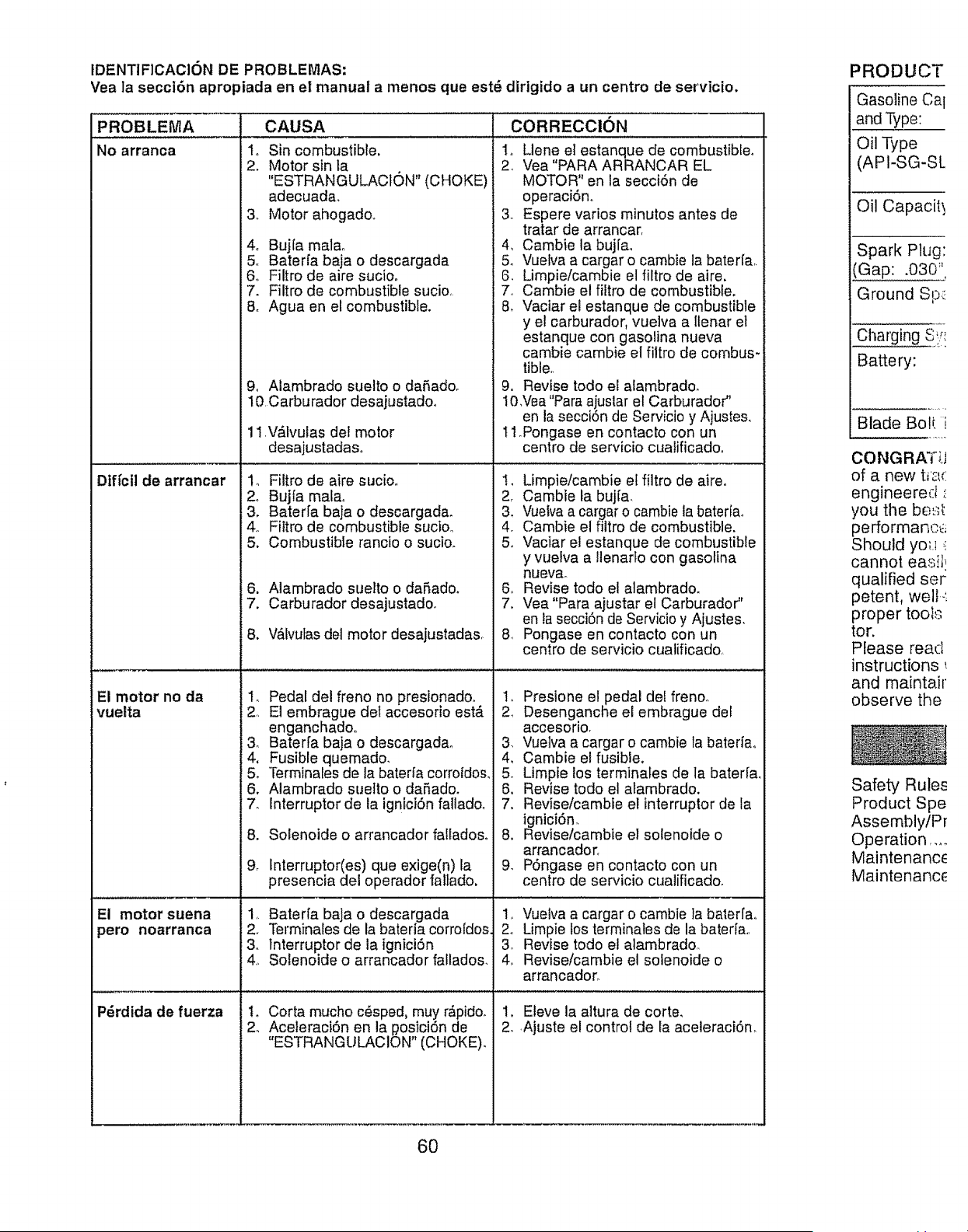
tDENT1FICACION DE PROBLEMAS:
Yea la seccl6n apropiada en el manual a menos que est_ dfrigido a un centro de servicio.
PROBLEMA
No arranca
Dtffcil de arrancar
El motor no da
vuelta
El motor suena
pero noarranca
P_rdida de fuerza
CAUSA
1o Sin combustible.
2, Motor sin la
"ESTRANGULAC10N" (CHOKE)
adecuada,
3o Motor ahogadoo
4o Bujfa malao
5. Baterfa baja o descargada
6,, Filtro de aire sucioo
7. Filtro de combustible sucio,
8o Agua en el combustible.
9, Alambrado suelto o dafiado.
10 Carburador desajustadoo
11,V#tlvulas del motor
desajustadas.
CORRECCION
1o Llene el estanque de combustible.
2. Vea "PARA ARRANCAR EL
MOTOR" en la secci6n de
operaciSn,
3o Espere varios minutos antes de
tratar de arrancar,
4, Cambie la bujra,
5. Vuelva a cargar o cambie la baterfar
6. Limpie/cambie el filtro de aire.
7, Cambie el filtro de combustible.
8, Vaclar el estanque de combustible
y el carburador, vuelva a llenar el
estanque con gasolina nueva
cambie cambie el filtro de combus*
tible.
9. Revise todo el alambrado.
10,Vea "Paraajuslar el Carburador"
en la secci6n de Servicio y Ajusteso
11.Pongase en contacto con un
centro de servicio cuaiificadoo
1, Filtro de aire sucioo
24 Bujfa real&
3. Baterfa baja o descargada.
4o Filtro de combustible sucioo
5. Combustible rancio o sucio.
6. Alambrado suelto odaSado_
7. Carburador desajustado.
8. V_lvulas del motor desajustadas,
I. Limpie/cambie el filtro de aire.
2_ Cambie la buj[a,
3. Vuelvaa cargar o cambie ta bateria,,
4. Cambie el filtro de combustible.
5_ Vaciar el estanque de combustible
y vuelva a llenarfo con gasolina
nuev&
6o Revise todo el alambrado.
7. Vea "Para ajustar el Carburador"
en la secci6n de Servicio y Ajustes,
8, Pongase en contacto con un
centro de servicio cualificado,
1. Pedal del freno no presionado.
2 El embrague det accesorio est,_
enganchado,
& Bater[a baja o descargadao
4, Fusible quemado.
5. Terminales de la baterla corrotdos_
6. Alambrado suetto o dafiado.
7. Interruptor de la ignicidn fallado.
8. Solenoide o arrancador falladoso
9_ Interruptor(es) que exige(n)la
presencia del operador fallado.
1, Baterfa baja o descargada
2. Terminales de la bateria corro[dos
3. Interruptor de la igniciSn
4. Solenoide o arrancador fallados.
t. Corta mucho c_sped, muy r,_pidoo
2. Aceleraci6n en la #osici6n de
"ESTRANGULACION" (CHOKE)_
1, Presione el pedal del frenoo
, Desenganche el embrague del
accesorio,
3. Vuelva a cargar o cambie la bateriao
4, Cambie el fusible,
5. Limpie los terminates de la bated&
6. Revise todo el alambrado.
7. Revise/cambie el interruptor de la
ignici6n.
8. Revise/cambie el solenoide o
arrancador.
9. P6ngase en contacto con un
centro de servicio cualificado,
1, Vuelva a cargar o cambie la baterrao
2. Limpie los terrninates de la bater[a,,
3. Revise todo el alambradoo
4_ Revise/cambie el solenoide o
arrancador.
1. Eleve la altura de corte,
2. Ajuste el control de la aceleraci6n,
PRODUCT
Gasoline Cal
and Type:
Oil Type
(API-SG-SL
Oil Capacit_
Spark Plug:
(Gap: .030 ''
Ground Sp_
Charging S'f_
Battery:
Blade Boll i
CONGRAT;J
of anew t_2,(
engineered
you the bes_
performanc_
Should yo_t
cannot easil_
qualified ser
petent, well.',
proper tools
tor.
Please read
instructions
and maintair
observe the
Safety Rules
Product Spe
Assembly/Pr
Operation ....
Maintenance
Maintenance
60
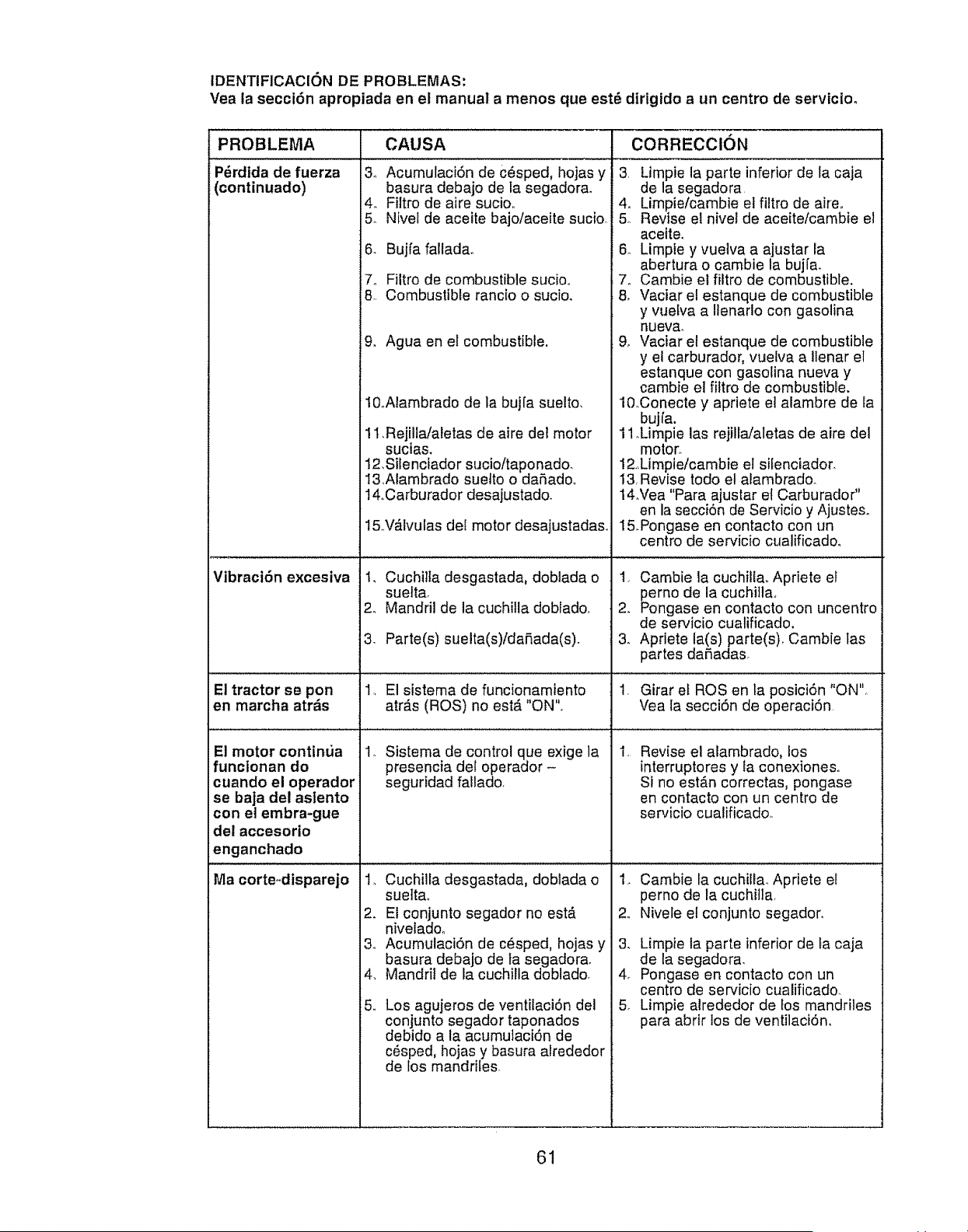
IDENTIFICACION DE PROBLEMAS:
Vea la secci6n apropiada en el manual amenos que est_ dirigido a un centro de servicioo
PROBLEMA CAUSA CORRECCION
P_rdtda de fuerza & 3. Limpie la parte inferior de la caja
(continuado) de la segadora
4. 4. Limpie/cambie et filtro de aire.
5o 5o Revise el nivel de aceite/cambie el
aceiteo
6- 6,. Limpie y vuelva a ajustar la
abertura o cambie la bujfa.
7o 7. Cambie el filtro de combustible.
8, 8. Vaciar el estanque de combustible
y vuelva a Ilenarlo con gasoline
nueva,
9. Agua en el combustible. 90 Vaciar el estanque de combustible
y el carburador, vuelva a Ilenar el
estanque con gasolina nueva y
cambie el filtro de combustible.
10oAlambrado de la bujfa suelto, l&Conecte y apriete et alambre de la
bujfa.
11.Rejilla/aletas de aire de! motor 1 1Mmpie las rejilla/aletas de aire del
sucias, motor_
12,Sifenciador sucio/taponado. 12,Limple/cambie el sifenciador.
13,Alambrado suefto o daSado,, 13,Revise todo el alambradoo
14.Carburador desajustado. 14.Vea "Para ajustar et Carburador"
en la secci6n de Servicio y Ajusteso
15.V_lvulas del motor desajustada& 15.Pongase en contacto con un
centro de servicio cualificadoo
Acumulaci6n de c6sped, hojas y
basura debajo de Ia segadora.
Filtro de aire sucio,,
Nivel de aceite bajolaceite sucio,
Bujfa falladao
Filtro de combustible sucio_
Combustible rancio o sucio.
Vibraci6n excesiva 1. Cuchilla desgastada, doblada o
suefta.
2. Mandril de la cuchilla doblado_
El tractor se port
en marcha atr_,s
1.. Sistema de control que exige la
presencia del operador -
seguridad fallado.
El motor contin_ia
funcionan do
cuando el operador
se baja del aslento
con et embra-gue
del accesorio
enganchado
2.
3- Parte(s) suelta(s)/daRada(s)o 3.
1. El sistema de funcionamtento I.
arras (ROS) no est,. "ON"+
Cambie la cuchillao Apriete el
perno de la cuchitla_
Pongase en contacto con uncentro
de ser_icio cualificado.
Apriete la(s)parte(s), Cambie las
partes da_adas
Girar el ROS en la posici6n "ON",
Vea la secci6n de operaci6n
Revise el alambrado, los
interruptores y ta conexiones..
Si no est_n correctas, pongase
en contacto con un centro de
servicio cualificado_
Ma corte-disparejo 1. Cuchilla desgastada, doblada o
suettao
2. El conjunto segador no est&
niveladoo
3,, Acumulaci6n de c_sped, hojas y
basura debajo de ta segadora.
4_ Mandril de la cuchilta doblado.
5,, Los agujeros de ventilaci6n del
conjunto segador taponados
debido ala acumutaci6n de
c_sped, hojas y basura alrededor
de los mandriles
2,,
3,
4o
5
Cambie la cuchill& Apriete el
perno de la cuchitla,
Nivele el conjunto segador,
Limpie la parte inferior de fa caja
de la segadora.
Pongase en contacto con un
centro de servicio cualificado.
Limpie alrededor de los mandriles
para abrir los de ventilaci6n,
61
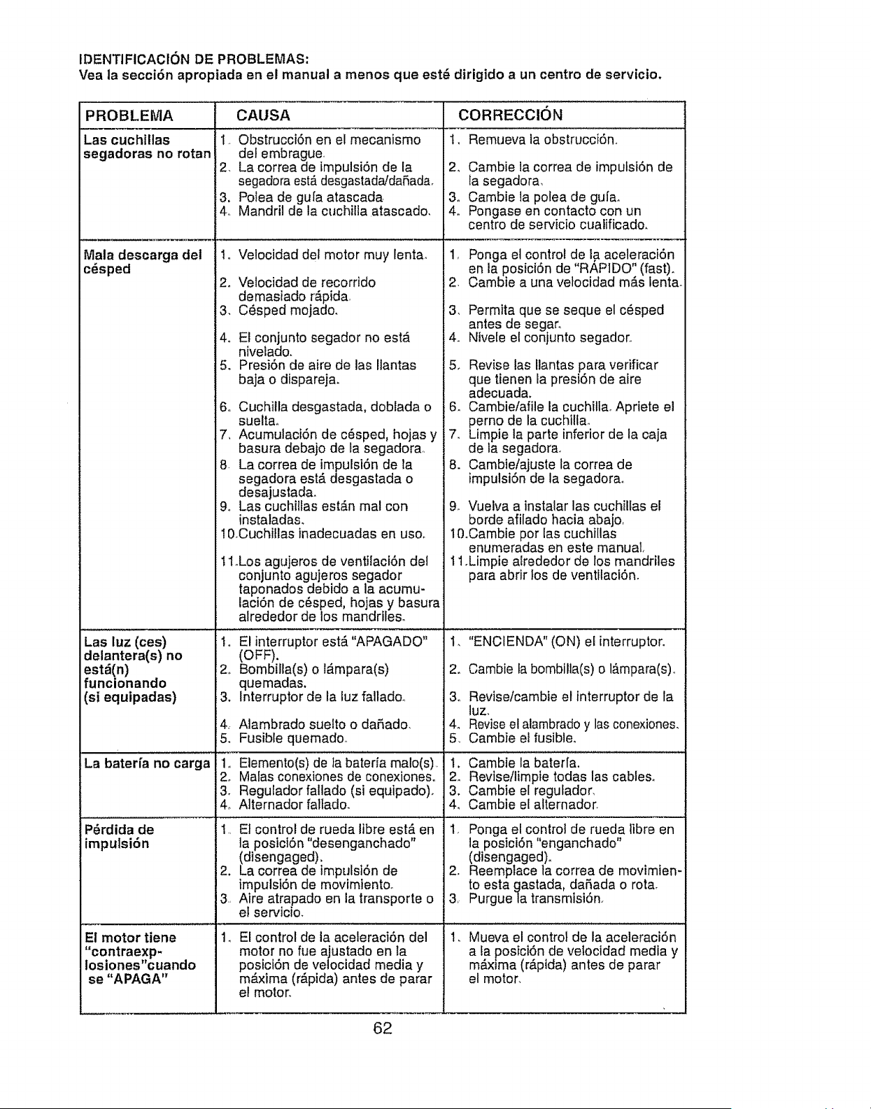
IDENTIFICACION DE PROBLEMAS:
Vea la secci6n apropiada en el manual amenos que est_ dirigido a un centro de servicto.
PROBLEMA
Las cuchiltas
segadoras no rotan
Mala descarga del
c_sped
Las luz (ces)
delantera(s) no
est,(n)
funcionando
(si equipadas)
,La baterra no carga
P6rdida de
impulsiSn
El motor tiene
"contraexp-
iosiones"cuando
se "APAGA"
CAUSA CORRECCION
1, Remueva ia obstrucci6n,,1, Obstrucci6n en et mecanismo
def embrague
2, La correa de impulsi6n de la
segadora est,, desgastada/daRada,
3. Polea de gu[a atascada
4, Mandril de la cuchilla atascado,
1, Velocidad del motor muy lenta,
2, Velocidad de recorrido
demasiado r&pida,
3, C_sped mojado.
4o El conjunto segador no est,.
nivelado.
5. Presi6n de aire de las Itantas
baja o dispareja.
6,, Cuchitla desgastada, doblada o
suelta,
7, Acumulaci6n de c6sped, hojas y
basura debajo de la segadora.
8 La correa de impulsi6n de la
segadora estA desgastada o
desajustada,
9,, Las cuchilfas est_n mal con
instaladas.
lOrOuchillas inadecuadas en uso,
11,Los agujeros de ventilaci6n del
conjunto agujeros segador
taponados debido a la acumu-
laci6n de c6sped, hojas y basura
alrededor de los mandriles,
I, El interrupter estA"APAGADO"
(OFF).
2o Bombilla(s) o l&mpara(s)
quemadas.
3, Interrupter de la iuz fallado.,
4, Alambrado suelto o daP,ado.
5. Fusible quemadoo
1_ Elemento(s) de la bateria male(s)•
2_ Mafas conexiones de conexioneso
, Regulador fallado (si equipado),
o Alternador fallado.
1,, El control de rueda fibre est#, en
]a posici6n "desenganchado"
(disengaged).
2. La correa de impulsi6n de
impulsi6n de movimiento,
3, Aire atrapado en la transporte o
el ser¢icio.
.El control de la aceleraci6n del
motor no fue ajustado en la
posici6n de velocidad media y
maxima (r,_pida) antes de parar
el motor,,
2, Cambie la correa de impulsi6n de
fa segadora,
3. Cambie la polea de gula.
4. Pongase en contacto con un
centre de servicio cualificado.
1, Ponga el control de la aceleraci6n
en la posici6n de "RAPIDO" (fast).
2, Cambie a una vetocidad m#,s lenta.
3, Permita que se seque el c_sped
antes de segar,,
4. Nlvele el conjunto segador,,
5, Revise las Ilantas para verificar
que tienen la presi6n de aire
adecuada.
6. Cambie!afile la cuchilta, Apriete el
perno de la cuchilla,
7, Limpie la parte inferior de la caja
de la segadora,
8. Cambie/ajuste la correa de
impulsi6n de la segadorao
9. Vuelva a instalar las cuchillas el
berde afilado hacia abajo,
l&Cambie per las cuchitlas
enumeradas en este manual,
11.Limpie alrededor de los mandriles
para abrir los de ventilaci6n,
1, "ENCIENDA" (ON) el interrupter,
2. Cambie la bombilla(s) e I_.mpara(s),,
3o Reviseicambie el interrupter de la
luz.
4o Reviseel alambrado y las conexiones.
5, Cambie el fusible,
1, Cambie la bater[a.
2. Revise/limpie todas las cables,
3. Cambie el regulador,
4, Cambie el alternador.
1, Ponga el control de rueda libre en
la posici6n "enganchado"
(disengaged)_
2. Reemplace ta correa de movimien-
to esta gastada, da5ada o rota.
3, Purgue la transmtsi6n.
Mueva el control de ia aceleraci6n
a la posici6n de vetocidad media y
maxima (r#.pida) antes de parar
el motor,
62
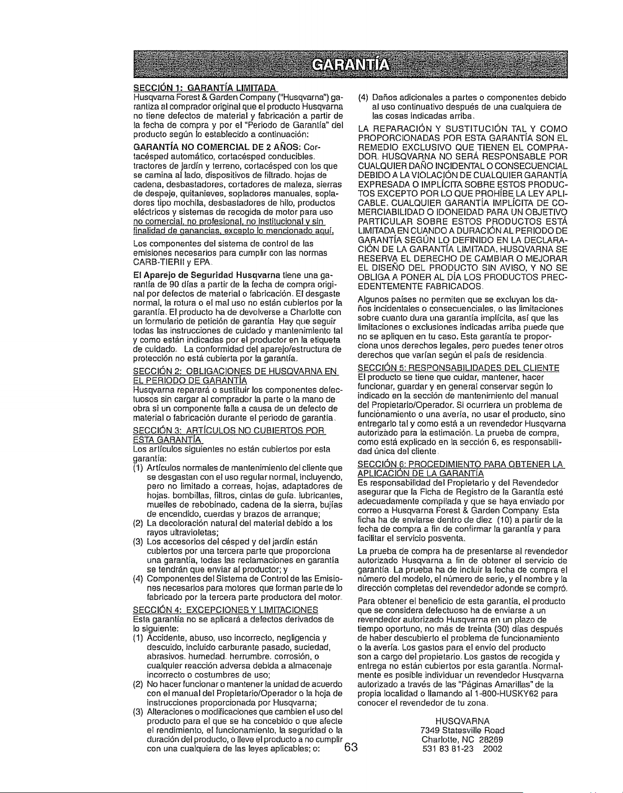
SECCION 1: GARANTfA LIMITADA
Husqvarna Forest & Garden Company ("Husqvarna") ga-
rantiza al comprador original que et productoHusqvarna
no tiene defectos de material y fabricaci6n a partir de
ia fecila de compra y per el "Periodo de Garantia" del
producto segt)n lo establecido a continuaci6n:
GARANTJA NO COMERCIAL DE 2 AI_OS: Cor-
tac_sped autom&tico, cortac_sped conducibtes,
tractores de jardi'n y terreno, cortac_sped con los qua
se camina al lade, dispositivos de fittrado, hojas de
cadena, desbasladeres, cortadores de maleza, sierras
de despeje, quitanieves, sopladores manuales, sopla-
dores tipo mochila, desbastadores de hilo, productos
el6ctricos y sistemas de recogida de mobr pare use
no comerciaL no #rofesiona!, no institucional v sin
finalidad de a_ncias, exceDto Io mencionado aquL
Los componentes del sistema de control de las
emisiones necesarios para cumplir con las normas
CARB-TfERII y EPA
El Aparejo de 8eguridad Husqvarna tiene una ga-
rant[a de 90 d(as a partir de la fecha de compra origi-
nal per defectos de material o fabricaci6n. El desgaste
normal, ]a rotura o e! ma! use no est_n cubiertos per la
garanl;[a. El producto ha de devolverse a Charlotte con
un formulario de petici6n de garantia Hay que seguir
lodes las instrucciones de cutdado y mantenimfento tal
y come esta'n indicadas per el productor en la etiqueta
de cuidadoo La conformidad del aparejo/estructura de
protecci6n no est& cubierta per la garantia..
SECCION 2: OBL]GAC1ONES DE HUSQVARNA EN
EL PERIODO DE GARANTJA
Husqvarna reparar& o sustituir los componentes defec-
tuosos sin cargar al comprador fa parte o la mane de
obra siun componente falla a cause de un delecto de
material o fabricaci6n durante el periodo de garantia.
SECCION 3: ARTJCULOS NO CUBIERTOS PeR
ESTA GARANTIA
Los art[culos siguientes no est_.n cubiertos per esla
garantfa:
(1) Artfculos normales de manlenimien!o del cliente que
se desgastan con et use regular normal, incluyendo,
pore no fimitado a correas, hojas, adaptadores de
hojas, bombillas, filtros, cintas de gu[a. lubricantes,
muelles de rebobinado, cadena de la sierra, bujias
de encendido, cuerdas y brazes de arranque;
(2) La decoloraci6n natural del material debido a los
rayos ultravioletas;
(3) Los accesodos det c_sped y del jardIn estAn
cubiertos per una tercera parte que proporciona
una garant[a, redes las reclamaciones en garantia
se tendr_.nque enviar al produclor;y
(4) Componentes del Sistema de Control de las Emisio-
nes necesados pare motores qua forman parle de lo
fabricado per la tercera parte productora del motor..
SECCION 4: EXCEPCIONES Y LtMITACIONES
Esta garantia no se aplicar_ a defectos derivados de
1osiguiente:
(1) Accidente, abuse, use incorrecto, negligencia y
descuido, incluido carburanb pasado, suciedad,
abrasives, humedad, herrumbre, corrosi6n, o
cualquier reacci6n adverse debida a almacenaje
incorrecto o costumbres de use;
(2) No hacer funcionar o mantener la unidad de acuerdo
con et manual dei Propietario/Operador o la hoja de
instrucciones proporcionada per Husqvarna;
(3) Alteraciones o modificaciones qua cambien el use del
producto para el que se ha concebido o qua afecte
el rendimiento, el funcionamiento, la seguridad o la
duraci6n det producto, o tleve el producto a no cumplir
con una cualquiera de las leyes aplicables; o:
(4) DaRes adicionales a partes o componenles debido
al use continuativo despu_s de una cualquiera de
las cases indicadas arriba.
LA REPARACI(3N Y SUSTITUC1ON TAL Y COMe
PROPORCIONADAS PeR ESTA GARANT1A SON EL
REMEDIO EXCLUSIVe QUE TIENEN EL COMPRA-
DOR. HUSQVARNA NO SERb, RESPONSABLE PeR
CUALQUIER DANe INCIDENTAL O CONSECUENCIAL
DEBIDO A LA VtOLACION DE CUALQUIER GARANT[A
EXPRESADA O IMPLICITA SOBRE ESTOS PRODUC-
TOS EXCEPTO PeR LO QUE PROH[BE LA LEY APLI-
CABLE, CUALQUIER GARANTJA IMPLiCITA DE CO-
MERCIABILIDAD O IDONEIDAD PARA UN OBJETIVO
PARTICULAR SOBRE ESTOS PRODUCTOS EST',
LIMITADA EN CUANDO A DURACIL')N AL PERIODO DE
GARANTIA SEGUN LO DEFINIDO EN LA DECLARA-
Ct6N DE LA GARANT[A LIMITADA. HUSQVARNA 8E
RESERVA EL DERECHO DE CAMBIAR O MEJORAR
EL DfSENO DEL PRODUCTO SIN AVfSO, Y NO SE
OBLIGA A PONER AL DtA LOS PRODUCTOS PREC-
EDENTEMENTE FABRfCADOS.
Algunos paises no permiten qua se excluyan los da-
Res incidentales o consecuenciales, o las limitaciones
sabra cuanto dura una garantia implicita, as[ que Ias
timilaciones o exctusiones indicadas arriba puede que
no se apliquen en tu case, Esta garantia te propor-
ciona unos detaches legales, pero puedes tenor otros
derechos que varIan segQn el pats de residencia.
SECCI6N 5: RESPONSABIL]DADES DEL CLIENTE
El producto se tiene qua cuidar, mantener, hacer
funcionar, guarder y en generaf conservar segdn Io
indicado en la secci6n de mantenimienio del manual
def Proptetario/Operador_ Si ocurdera un problema de
funcionamiento o una averia, no user el producto, sine
entregarb tel y come est& a un revendedor Husqvarna
autorizb_dopara la estimaci6n. La prueba de compra,
come est,_ explicado en la secci6n 6, es responsabili-
dad _nica del cliente,
SECC!ON 6: PROCEDtMIENTO PARA OBTENER
APLICACION DE LA GARANTiA
Es responsabifidad del Propietario y del Revendedor
asegurar que la Ficha de Registro de ia Garantia est_
adecuadamenle compilada y que se haya enviado per
correo a Husqvarna Forest & Garden Company Esla
fiche ha de enviarse dentro de diez (I0) a partir de la
techa de compra a fin de confirmar la garanl[a y pare
facilitar el servicio posventa,.
La prueba de compra ha de presenlarse al revendedor
autorizado Husqvarna a fin de obtener el servicio de
garantia. La prueba ha de incluir la fecha de compra el
n0mero dot modelo, et nOmero de serie, y el nombre y la
direcci6n completes del revendedor adonde se compr6.
Para obtaner el beneficio de esta garantta, e! producto
que so considera detectuoso ha de enviarse a un
revendedor autorizado Husqvarna en un plazo de
tiempo oportuno, no mrs de treinta (30) dias despu6s
de haber descubierto el problema de funcionamienlo
o ta averia, Los gastos para el envio del producto
son a cargo de] propietario. Los gastos de recogida y
entrega no estAn cubiertos per esta garantia. NormaF
mente es posible individuar un revendedor Husqvarna
autorizado a trav6s de las "P,Cginas Amarillas" de la
propia Iocalidad ollamando al 1-800-HUSKY62 pare
conocer el revendedor de tu zona.
63
HUSQVARNA
7349 Statesville Road
Charlotte, NC 28269
53t 83 81-23 2002
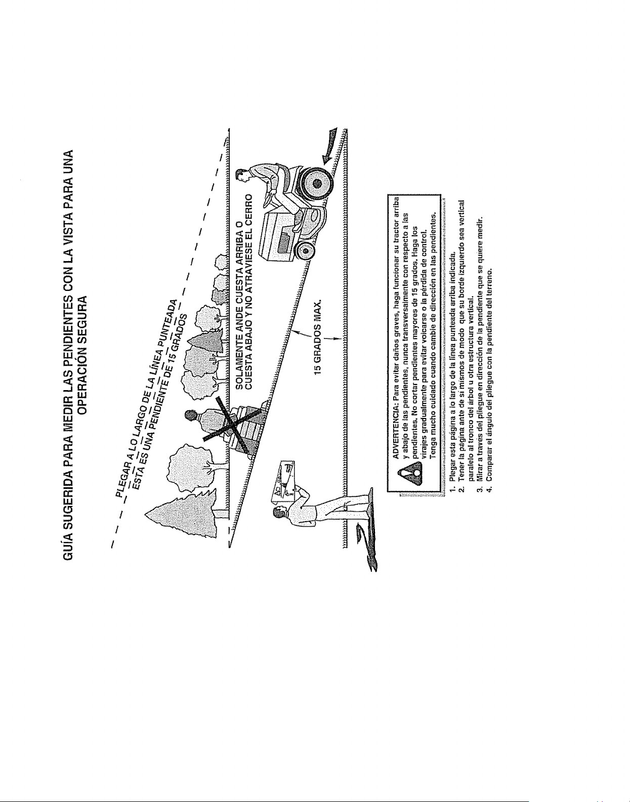
Z
r,
or_
H
..I
Z
0
0
W_
ZO
Lu,,,
r'_o')
ZZ
W
oO
w
N
n
Q
rr
W
o
m
i t
I
I
1
I
1
I
I
I
I
r_
xl
_'_o
m_"
--O_a_o
N _,11
,-,NO
,ON r44