
i
LAUNCH
TOUCH PRO ELITE User Manual
Copyright Information
Copyright © 2020 by LAUNCH TECH CO., LTD. All rights reserved. No part of
this publication may be reproduced, stored in a retrieval system, or transmitted in
any form or by any means, electronic, mechanical, photocopying and recording
or otherwise, without the prior written permission of LAUNCH. The information
contained herein is designed only for the use of this unit. LAUNCH is not
responsible for any use of this information as applied to other units.
Statement: LAUNCH owns the complete intellectual property rights for the software
used by this product. For any reverse engineering or cracking actions against the
software, LAUNCH will block the use of this product and reserve the right to pursue
their legal liabilies.
Trademark Information
LAUNCH is a registered trademark of LAUNCH TECH CO., LTD. (also called
LAUNCH for short) in China and other countries. All other LAUNCH trademarks,
service marks, domain names, logos, and company names referred to in this
manual are either trademarks, registered trademarks, service marks, domain
names, logos, company names of or are otherwise the property of LAUNCH or
its aliates. In countries where any of the LAUNCH trademarks, service marks,
domain names, logos and company names are not registered, LAUNCH claims
other rights associated with unregistered trademarks, service marks, domain
names, logos, and company names. Other products or company names referred
to in this manual may be trademarks of their respective owners. You may not use
any trademark, service mark, domain name, logo, or company name of LAUNCH
or any third party without permission from the owner of the applicable trademark,
service mark, domain name, logo, or company name. You may contact LAUNCH
by visiting the website at www.cnlaunch.com, or writing to LAUNCH TECH CO.,
LTD., Launch Industrial Park, North of Wuhe Avenue, Banxuegang, Bantian,
Longgang, Shenzhen, Guangdong, P.R.China, to request written permission to
use Materials on this manual for purposes or for all other questions relating to
this manual.
General Notice
• Other product names used herein are for identification purposes only and
may be trademarks of their respective owners. LAUNCH disclaims any and all
rights in those marks.
• There is a possibility that this unit is inapplicable to some of the vehicle
models or systems listed in the diagnosis section due to dierent countries,
areas, and/or years. Do not hesitate to contact LAUNCH if you come across
such questions. We are to help you solve the problem as soon as possible.

ii
LAUNCH
TOUCH PRO ELITE User Manual
Disclaimer
• To take full advantage of the unit, you should be familiar with the engine.
• All information, illustrations, and specications contained in this manual are
based on the latest information available at the time of publication. The right
is reserved to make change at any time without notice.
• Neither LAUNCH nor its aliates shall be liable to the purchaser of this unit
or third parties for damages, losses, costs or expenses incurred by purchaser
or third parties as a result of: accident, misuse, or abuse of this unit, or
unauthorized modifications, repairs, or alterations to this unit, or failure to
strictly comply with LAUNCH operating and maintenance instructions.
• LAUNCH shall not be liable for any damages or problems arising from the
use of any options or any consumable products other than those designated
as Original LAUNCH Products or LAUNCH Approved Products by LAUNCH.
Safety Precautions and Warnings
To prevent personal injury or damage to vehicles and/or this tool, please read
this user’s manual rst carefully and observe the following safety precautions at
a minimum whenever working on a vehicle:
• Always perform automotive testing in a safe environment.
• Do not attempt to operate or observe the tool while driving a vehicle.
Operating or observing the tool will cause driver distraction and could cause a
fatal accident.
• Wear safety eye protection that meets ANSI standards.
• Keep clothing, hair, hands, tools, test equipment, etc. away from all moving or
hot engine parts.
• Operate the vehicle in a well-ventilated work area: Exhaust gases are
poisonous.
• Put blocks in front of the drive wheels and never leave the vehicle unattended
while running tests.
• Use extreme caution when working around the ignition coil, distributor cap,
ignition wires and spark plugs. These components create hazardous voltages
when the engine is running.
• Put the transmission in P (for A/T) or N (for M/T) and make sure the parking
brake is engaged.
• Keep a re extinguisher suitable for gasoline/chemical/ electrical res nearby.
• Don’t connect or disconnect any test equipment while the ignition is on or the
engine is running.

iii
LAUNCH
TOUCH PRO ELITE User Manual
• Keep this tool dry, clean, free from oil/water or grease. Use a mild detergent
on a clean cloth to clean the outside of the tool, when necessary.
• Please use the 5 V DC power adaptor to charge this tool. No responsibility
can be assumed for any damage or loss caused as a result of using power
adaptors other than the right one.
FCC Statement:
Any Changes or modications not expressly approved by the party responsible for compliance
could void the user’s authority to operate the equipment.
This device complies with part 15 of the FCC Rules. Operation is subject to the following
two conditions: (1) This device may not cause harmful interference, and (2) this device must
accept any interference received, including interference that may cause undesired operation.
Note: This equipment has been tested and found to comply with the limits for a
Class B digital device, pursuant to Part 15 of the FCC Rules. These limits are designed
to provide reasonable protection against harmful interference in a residential installation.
This equipment generates, uses, and can radiate radio frequency energy, and if not
installed and used in accordance with the instructions, may cause harmful interference
to radio communications. However, there is no guarantee that interference will not occur
in a particular installation. If this equipment does cause harmful interference to radio or
television reception, which can be determined by turning the equipment o and on, the user
is encouraged to try to correct the interference by one or more of the following measures:
- Reorient or relocate the receiving antenna.
- Increase the separation between the equipment and receiver.
- Connect the equipment into an outlet on a circuit different from that to which the
receiver is connected.
- Consult the dealer or an experienced radio/TV technician for help.
TOUCH PRO ELITE (FCC ID: XUJPROELITE) has been evaluated to meet general RF
exposure requirement. The highest reported SAR value is 0.58W/kg. This device was tested
for typical body-worn operations with the back of the handset kept 0mm from the body.
The use of accessories that do not satisfy these requirements may not comply with FCC RF
exposure requirements, and should be avoided.
Hereby, Launch Tech Co., Ltd. declares that this Professional Diagnostic Tool (Model TOUCH
PRO ELITE) is in compliance with the essential Requirements and other relevant provisions
of Radio Equipment Directive 2014/53/EU.
Operation frequency and Max. RF output power:
WiFi 802.11b/g/n(2.4G): 2412-2472MHz, 18.92dBm;
The RF frequencies can be used in Europe without restriction.

iv
LAUNCH
TOUCH PRO ELITE User Manual
Table of Contents
1. Introduction ........................................................................................... 1
2. General Information .............................................................................. 3
2.1 On-Board Diagnostics (OBD) I ........................................................... 3
2.2 On-Board Diagnostics (OBD) II .......................................................... 3
2.3 Diagnostic Trouble Codes (DTCs) ...................................................... 5
2.4 Location of the Data Link Connector (DLC)........................................ 6
2.5 OBD II Terminology ............................................................................ 7
2.6 OBD II Monitors .................................................................................. 9
2.6.1 Continuous Monitors........................................................................ 9
2.6.2 Non-Continuous Monitors ................................................................ 10
2.6.3 OBD II Reference Table ................................................................... 14
2.7 DTCs and MIL Status ......................................................................... 15
3. Components and Controls .................................................................... 18
3.1 Controls .............................................................................................. 18
3.2 Technical Specications ..................................................................... 19
3.3 Accessory List..................................................................................... 20
4. Initial Use .............................................................................................. 21
4.1 Charging the Tool ............................................................................... 21
4.2 Getting Started ................................................................................... 21
5. Diagnose .............................................................................................. 25
5.1 Connection ......................................................................................... 25

v
LAUNCH
TOUCH PRO ELITE User Manual
5.2 System Diagnosing............................................................................. 25
5.2.1 Smart Diagnosis (Auto-Detect) ........................................................ 25
5.2.2 Manual Diagnosis ............................................................................ 27
5.3 OBDII Diagnosis ................................................................................. 34
5.4 History ................................................................................................ 37
5.5 Resetting ............................................................................................ 39
6. Update .................................................................................................. 42
7. Data ...................................................................................................... 43
7.1 Diagnostic Report ............................................................................... 43
7.2 Diagnostic Record .............................................................................. 43
7.3 DTC Library ........................................................................................ 44
7.4 DLC(Data Link Connector) Location................................................... 45
7.5 Feedback ............................................................................................ 45
7.6 Firmware Fix ....................................................................................... 45
7.7 FAQ .................................................................................................... 45
7.8 Image.................................................................................................. 45
8. Settings................................................................................................. 46
8.1 Units of Measurement ........................................................................ 46
8.2 Screen Capture .................................................................................. 46
8.3 Automatic Detection on Connect ........................................................ 46
8.4 Display & Brightness .......................................................................... 46

vi
LAUNCH
TOUCH PRO ELITE User Manual
8.5 Sound ................................................................................................. 46
8.6 Network .............................................................................................. 46
8.7 Date/Time ........................................................................................... 47
8.8 Language............................................................................................ 47
8.9 Email Setup ........................................................................................ 47
8.10 Recovery .......................................................................................... 47
8.11 Clean up ........................................................................................... 47
8.12 About ................................................................................................ 47
9. FAQ ...................................................................................................... 48

1
LAUNCH
TOUCH PRO ELITE User Manual
1. Introduction
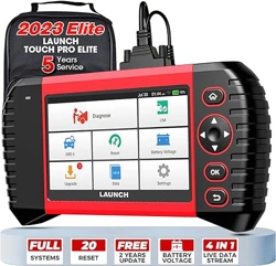
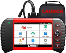
TOUCH PRO ELITE Diagnostic Tool is an evolutionary smart solution for
passenger car diagnosis. It inherits LAUNCH’s advanced diagnosing technology
and is characterized by covering a wide range of vehicles and providing precise
test result and powerful functions.
It has the following functions and advantages:
• Smart (Auto-Detect) Diagnosis: Once the tool and the vehicle are properly
connected, the system starts auto-detect process. Once the whole process is
successfully nished, a diagnostic report will be automatically generated and
sent to your email box (if bound).
• Manual Diagnosis: If Auto-Detect failure occurs, manual diagnosis is also
available. Diagnosis functions include: Version Information, Read DTCs,
Clear DTCs and Read Data Stream (supports 3 display modes: Value, Graph
and Merged).
• OBDII Diagnosis: 10 modes of OBD II test are supported, including EVAP, O
2
Sensor, I/M Readiness, MIL Status, VIN Info, and On-board monitors testing
etc.
• Reset: Available maintenance and reset functions include Oil Lamp Reset,
Steering Angle Sensor (SAS) Reset, Electronic Parking Brake (EPB), Battery
Maintenance System (BMS) Reset, Diesel Particulate Filter (DPF), Electronic
Throttle Position Reset, ABS bleeding
.
• One-click Update: Let you update your diagnostic software and APK online.
• Diagnostic History: This function provides a quick access to the tested
vehicles and users can choose to view the test report or resume from the last
operation, without the necessity of starting from scratch.
• Diagnostic Feedback: Use this option to submit the vehicle issue to us for
analysis and troubleshooting.
• DTC Library: Allows you to retrieve the definition of the diagnostic trouble
code from the abundant DTC database.
• Displays battery real-time voltage once properly connected to the vehicle.
• Touch & Keypad input are supported.
This tool is specially designed to work with most OBD II compliant vehicles,
including Controller Area Network (CAN). It is required by EPA that all 1996 and
newer vehicles (cars and light trucks) sold in the United States must be OBD II
compliant and this includes all American, Asian and European vehicles.
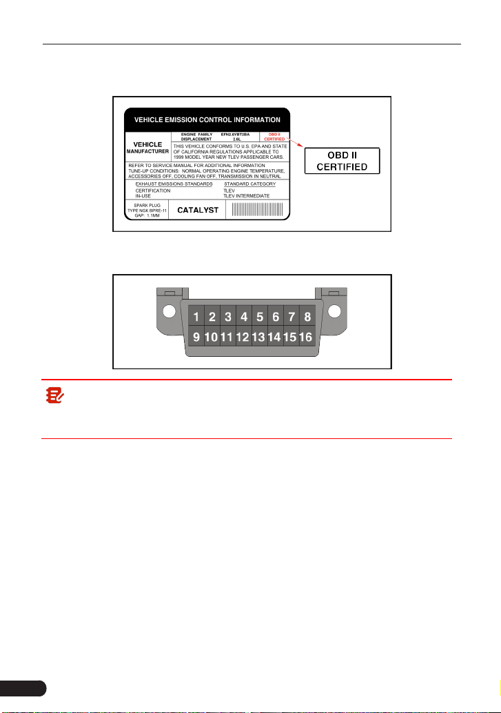
A small number of 1994 and 1995 model year gasoline vehicles are OBD II
compliant. To verify if a 1994 or 1995 vehicle is OBD II compliant, check the
following:
1.
Vehicle Emissions Control Information (VECI) Label
. It is located under the
2
LAUNCH
TOUCH PRO ELITE User Manual
hood or by the radiator of most vehicles. If the vehicle is OBD II compliant,
the label will designate “OBD II Certied”.
2. Government regulations mandate that all OBD II compliant vehicles
must
have a “common” 16-pin
Data Link Connector (DLC)
.
Note: Some 1994 and 1995 vehicles have 16-pin connectors but are not
OBD II compliant. Only those vehicles with a Vehicle Emissions Control Label
stating “OBD II Certied” are OBD II compliant.

3
LAUNCH
TOUCH PRO ELITE User Manual
2. General Information
2.1 On-Board Diagnostics (OBD) I
Note: With the exception of some 1994 and 1995 vehicles, most vehicles
from 1982 to 1995 are equipped with some type of rst generation On-Board
Diagnostics.
Beginning in 1988, California’s Air Resources Board (CARB), and later the
Environmental Protection Agency (EPA) required vehicle manufacturers to
include a self-diagnostic program in their on-board computers. The program
would be capable of identifying emissions-related faults in a system. The first
generation of Onboard Diagnostics came to be known as OBD I.
OBD I is a set of self-testing and diagnostic instructions programmed into the
vehicle’s onboard computer. The programs are specically designed to detect
failures in the sensors, actuators, switches and wiring of the various vehicle
emissions-related systems. If the computer detects a failure in any of these
components or systems, it lights an indicator on the dashboard to alert the driver.
The indicator lights only when an emissions-related problem is detected.
The computer also assigns a numeric code for each specific problem that it
detects, and stores these codes in its memory for later retrieval. These codes
can be retrieved from the computer’s memory with the use of a “Code Reader”
or a “Diagnostic Tool.”
2.2 On-Board Diagnostics (OBD) II
As technology evolved and the desire to improve the On-Board Diagnostic
system increased, a new generation of On-Board Diagnostic system was
developed. This second generation of On-Board Diagnostic regulations is called
“OBD II”.
In addition to performing all the functions of the OBD I System, the OBD II
System has been enhanced with new Diagnostic Programs. These programs
closely monitor the functions of various emissions-related components and
systems (as well as other systems) and make this information readily available
(with the proper equipment) to the technician for evaluation.
The California Air Resources Board (CARB) conducted studies on OBD I
equipped vehicles. The information that was gathered from these studies
showed the following:
• A large number of vehicles had deteriorating or degraded emissions-related

4
LAUNCH
TOUCH PRO ELITE User Manual
components. These components were causing an increase in emissions.
• Because OBD I systems only detect failed components, the degraded
components were not setting codes.
• Some emissions problems related to degraded components only occur
when the vehicle is being driven under a load. The emission checks being
conducted at the time were not performed under simulated driving conditions.
As a result, a signicant number of vehicles with degraded components were
passing Emissions Tests.
• Codes, code definitions, diagnostic connectors, communication protocols
and emissions terminology were dierent for each manufacturer. This caused
confusion for the technicians working on dierent make and model vehicles.
To address the problems made evident by this study, CARB and the EPA passed
new laws and standardization requirements. These laws required that vehicle
manufacturers to equip their new vehicles with devices capable of meeting
all of the new emissions standards and regulations. It was also decided that
an enhanced on-board diagnostic system, capable of addressing all of these
problems, was needed. This new system is known as “On-Board Diagnostics
Generation Two (OBD II).” The primary objective of the OBD II system is to
comply with the latest regulations and emissions standards established by CARB
and the EPA.
The Main Objectives of the OBD II System are:
• To detect degraded and/or failed emissions-related components or systems
that could cause tailpipe emissions to exceed by 1.5 times the Federal Test
Procedure (FTP) standard.
• To expand emissions-related system monitoring. This includes a set of
computer run diagnostics called Monitors. Monitors perform diagnostics and
testing to verify that all emissions-related components and/or systems are
operating correctly and within the manufacturer’s specications.
• To use a standardized Diagnostic Link Connector (DLC) in all vehicles.
(Before OBD II, DLCs were of dierent shapes and sizes.)
• To standardize the code numbers, code definitions and language used to
describe faults. (Before OBD II, each vehicle manufacturer used their own
code numbers, code denitions and language to describe the same faults.)
• To expand the operation of the Malfunction Indicator Lamp (MIL).
• To standardize communication procedures and protocols between the
diagnostic equipment (Diagnostic Tools, Code Readers, etc.) and the
vehicle’s on-board computer.

5
LAUNCH
TOUCH PRO ELITE User Manual
2.3 Diagnostic Trouble Codes (DTCs)
OBD II Diagnostic Trouble Codes are codes that are stored by the on-board
computer diagnostic system in response to a problem found in the vehicle. These
codes identify a particular problem area and are intended to provide you with a
guide as to where a fault might be occurring within a vehicle.
DO NOT
replace
parts based only on DTCs without rst consulting the vehicle’s service manual
for proper testing procedures for that particular system, circuit or component.
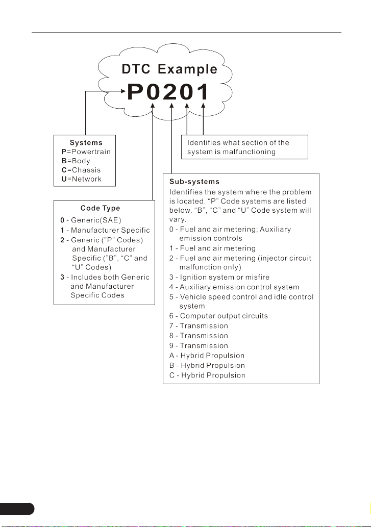
OBD II Diagnostic Trouble Codes consist of a ve-digit alphanumeric code.
• The 1st character is a
letter
(B, C, P or U). It identifies the “main system”
where the fault occurred (Body, Chassis, Powertrain, or Network).
• The 2nd character is a
numeric digit
(0 thru 3). It identies the “type” of code
(Generic or Manufacturer-Specic).
Note: Generic DTCs are codes that are used by all vehicle
manufacturers. The standards for generic DTCs, as well as their
denitions, are set by the Society of Automotive Engineers (SAE).
Manufacturer-Specific DTCs are codes that are controlled by the
vehicle manufacturers. The Federal Government does not require
vehicle manufacturers to go beyond the standardized generic DTCs in
order to comply with the new OBD II emissions standards. However,
manufacturers are free to expand beyond the standardized codes to make
their systems easier to diagnose.
• The 3rd character is a letter or a
numeric digit
(0 thru 9, A thru F). It identies
the specic system or sub-system where the problem is located.
• The 4th and 5th characters are
letters
or
numeric digits
(0 thru 9, A thru F).
They identify the section of the system that is malfunctioning.
6
LAUNCH
TOUCH PRO ELITE User Manual
P0201 - Injector circuit malfunction, Cylinder 1
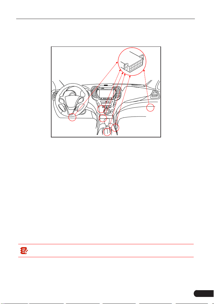
2.4 Location of the Data Link Connector (DLC)
The DLC (Data Link Connector or Diagnostic Link Connector) is typically a 16-
pin connector where diagnostic code readers interface with the vehicle’s on-
board computer. The DLC is usually located 12 inches from the center of the
instrument panel (dash), under or around the driver’s side for most vehicles. If
Data Link Connector is not located under dashboard, a label should be there
7
LAUNCH
TOUCH PRO ELITE User Manual
telling location. For some Asian and European vehicles, the DLC is located
behind the ashtray and the ashtray must be removed to access the connector. If
the DLC cannot be found, refer to the vehicle’s service manual for the location.
Potential DLC Location
2.5 OBD II Terminology
The following terms and their denitions are related to OBD II systems. Read
and reference this list as needed to aid in the understanding of OBD II systems.
Powertrain Control Module (PCM)
-- The PCM is the OBD II accepted term
for the vehicle’s “on-board computer.” In addition to controlling the engine
management and emissions systems, the PCM also participates in controlling
the powertrain (transmission) operation. Most PCMs also have the ability to
communicate with other computers on the vehicle (ABS, ride control, body, etc.).
Monitors
-- Monitors are “diagnostic routines” programmed into the PCM. The
PCM utilizes these programs to run diagnostic tests, and to monitor operation
of the vehicle’s emissions-related components or systems to ensure they
are operating correctly and within the vehicle’s manufacturer specifications.
Currently, up to fteen Monitors are used in OBD II systems. Additional Monitors
will be added as the OBD II system is further developed.
Note: Not all vehicles support all fteen Monitors.
Enabling Criteria
-- Also termed Enabling Conditions. They are the vehicle-
specic events or conditions that must occur within the engine before the various
monitors will set, or run. Some monitors require the vehicle to follow a prescribed
“drive cycle” routine as part of the enabling criteria. Drive cycles vary among

8
LAUNCH
TOUCH PRO ELITE User Manual
vehicles and for each monitor in any particular vehicle. Please refer to the
vehicle’s factory service manual for specic enabling procedures.
Trip
- A Trip for a particular Monitor requires that the vehicle is being driven in
such a way that all the required “Enabling Criteria” for the Monitor to run and
complete its diagnostic testing are met. The “Trip Drive Cycle” for a particular
Monitor begins when the ignition key is turned “On.” It is successfully completed
when all the “Enabling Criteria” for the Monitor to run and complete its diagnostic
testing are met by the time the ignition key is turned “Off.” Since each of the
fifteen monitors is designed to run diagnostics and testing on a different part
of the engine or emissions system, the “Trip Drive Cycle” needed for each
individual Monitor to run and complete varies.
OBD II Drive Cycle
-- A specific mode of vehicle operation that provides
conditions required to set all the readiness monitors applicable to the vehicle to
the “ready” condition. The purpose of completing an OBD II drive cycle is to force
the vehicle to run its onboard diagnostics. Some form of a drive cycle needs to
be performed after DTCs have been erased from the PCM’s memory or after
the battery has been disconnected. Running through a vehicle’s complete drive
cycle will “set” the readiness monitors so that future faults can be detected. Drive
cycles vary depending on the vehicle and the monitor that needs to be reset. For
vehicle specic drive cycle, consult the service manual.
Note: Do not confuse a “Trip” Drive Cycle with an OBD II Drive Cycle. A
“Trip” Drive Cycle provides the “Enabling Criteria” for one specic Monitor to
run and complete its diagnostic testing. An OBD II Drive Cycle must meet the
“Enabling Criteria” for all Monitors on a particular vehicle to run and complete
their diagnostic testing.
Warm-up Cycle
- Vehicle operation after an engine off period where engine
temperature rises at least 40°F (22°C) from its temperature before starting, and
reaches at least 160°F (70°C). The PCM uses warm-up cycles as a counter to
automatically erase a specic code and related data from its memory. When no
faults related to the original problem are detected within a specied number of
warm-up cycles, the code is erased automatically.
Fuel Trim (FT)
- Feedback adjustments to the base fuel schedule. Short-term
fuel trim refers to dynamic or instantaneous adjustments. Long-term fuel trim
refers to much more gradual adjustments to the fuel calibration schedule than
short-term trim adjustments. These long-term adjustments compensate for
vehicle dierences and gradual changes that occur over time.

9
LAUNCH
TOUCH PRO ELITE User Manual
2.6 OBD II Monitors
An important part of a vehicle’s OBD II system is the Readiness Monitors, which
are indicators used to find out if all of the emissions components have been
evaluated by the OBD II system. They are running periodic tests on specific
systems and components to ensure that they are performing within allowable
limits.
Monitor operation is either “Continuous” or “Non-Continuous,” depending on the
specic monitor.
2.6.1 Continuous Monitors
Some of the vehicle components or systems are continuously tested by the
vehicle’s OBD II system, while others are tested only under specific vehicle
operating conditions. The continuously monitored components listed below are
always ready:
1. Misre Monitor
This Monitor continuously checks for engine misres. A misre occurs when the
air-fuel mixture in the cylinder does not ignite. The misre Monitor uses changes
in crankshaft speed to sense an engine misre. When a cylinder misres, it no
longer contributes to the speed of the engine, and engine speed decreases each
time the aected cylinder(s) misre. The misre Monitor is designed to sense
engine speed fluctuations and determine from which cylinder(s) the misfire is
coming, as well as how bad the misre is.
There are three types of engine misres, Types 1, 2, and 3.
• Type 1 and Type 3 misfires are two-trip monitor faults. If a fault is sensed
on the rst trip, the computer temporarily saves the fault in its memory as a
Pending Code. The MIL is not commanded on at this time. If the fault is found
again on the second trip, under similar conditions of engine speed, load and
temperature, the computer commands the MIL “On,” and the code is saved in
its long term memory.
• Type 2 misres are the most severe type of misre. When a Type 2 misre
is sensed on the rst trip, the computer commands the MIL to light when the
misre is sensed. If the computer determines that a Type 2 misre is severe,
and may cause catalytic converter damage, it commands the MIL to “ash”
once per second as soon as the misfire is sensed. When the misfire is no
longer present, the MIL reverts to steady “On” condition.
The Misfire Monitor is supported by both “spark ignition” vehicles and
“compression ignition” vehicles.

10
LAUNCH
TOUCH PRO ELITE User Manual
2. Fuel System Monitor
This Monitor uses a Fuel System Correction program, called Fuel Trim, inside
the on-board computer. Fuel Trim is a set of positive and negative values that
represent adding or subtracting fuel from the engine. This program is used
to correct for a lean (too much air/not enough fuel) or rich (too much fuel/not
enough air) air-fuel mixture. The program is designed to add or subtract fuel,
as needed, up to a certain percent. If the correction needed is too large and
exceeds the time and percent allowed by the program, a fault is indicated by the
computer.
The Fuel System Monitor is supported by both “spark ignition” vehicles and
“compression ignition” vehicles. The Fuel System Monitor may be a “One-Trip”
or “Two-Trip” Monitor, depending on the severity of the problem.
3. Comprehensive Components Monitor (CCM)
This Monitor continuously checks all inputs and outputs from sensors, actuators,
switches and other devices that provide a signal to the computer. The Monitor
checks for shorts, opens, out of range value, functionality and “rationality* (
See
Note
).”
Rationality: Each input signal is compared against all other inputs and
against information in the computer’s memory to see if it makes sense under
the current operating conditions.
Example: The signal from the throttle position sensor indicates the vehicle is
in a wide-open throttle condition, but the vehicle is really at idle, and the idle
condition is confirmed by the signals from all other sensors. Based on the
input data, the computer determines that the signal from the throttle position
sensor is not rational (does not make sense when compared to the other
inputs). In this case, the signal would fail the rationality test.
The CCM is supported by both “spark ignition” vehicles and “compression
ignition” vehicles. The CCM may be either a “One-Trip” or a “Two-Trip” Monitor,
depending on the component.
2.6.2 Non-Continuous Monitors
“Non-continuous” Monitors perform and complete their testing once per trip. The
“non-continuous” Monitors are:
1. O
2
Sensor Monitor
The Oxygen Sensor monitors how much oxygen is in the vehicle’s exhaust. It
generates a varying voltage of up to one volt, based on how much oxygen is in
the exhaust gas, and sends the signal to the computer. The computer uses this

11
LAUNCH
TOUCH PRO ELITE User Manual
signal to make corrections to the air/fuel mixture. If the exhaust gas has a large
amount of oxygen (a lean air/fuel mixture), the oxygen sensor generates a “low”
voltage signal. If the exhaust gas has very little oxygen (a rich mixture condition),
the oxygen sensor generates a “high” voltage signal. A 450mV signal indicates
the most ecient, and least polluting, air/fuel ratio of 14.7 parts of air to one part
of fuel.
The oxygen sensor must reach a temperature of at least 600-650°F, and the
engine must reach normal operating temperature, for the computer to enter into
closed-loop operation.
The oxygen sensor only functions when the computer is in closed-loop. A
properly operating oxygen sensor reacts quickly to any change in oxygen content
in the exhaust stream. A faulty oxygen sensor reacts slowly, or its voltage signal
is weak or missing.
The Oxygen Sensor Monitor is supported by “spark ignition” vehicles only. The
Oxygen Sensor Monitor is a “Two-Trip” monitor. If a fault is found on the rst trip,
the computer temporarily saves the fault in its memory as a Pending Code. The
computer does not command the MIL on at this time. If the fault is sensed again
on the second trip, the computer commands the MIL “On,” and saves the code in
its long-term memory.
2. O
2
Sensor Heater Monitor
The Oxygen Sensor Heater Monitor tests the operation of the oxygen sensor’s
heater. There are two modes of operation on a computer-controlled vehicle:
“open-loop” and “closed-loop.” The vehicle operates in open-loop when the
engine is cold, before it reaches normal operating temperature. The vehicle
also goes to open-loop mode at other times, such as heavy load and full throttle
conditions. When the vehicle is running in open-loop, the oxygen sensor signal is
ignored by the computer for air/fuel mixture corrections. Engine eciency during
open-loop operation is very low, and results in the production of more vehicle
emissions.
Closed-loop operation is the best condition for both vehicle emissions and
vehicle operation. When the vehicle is operating in closed-loop, the computer
uses the oxygen sensor signal for air/fuel mixture corrections.
In order for the computer to enter closed-loop operation, the oxygen sensor
must reach a temperature of at least 600°F. The oxygen sensor heater helps the
oxygen sensor reach and maintain its minimum operating temperature (600°F)
more quickly, to bring the vehicle into closed-loop operation as soon as possible.
The Oxygen Sensor Heater Monitor is supported by “spark ignition” vehicles
only. The Oxygen Sensor Heater Monitor is a “Two-Trip” Monitor. If a fault is
found on the rst trip, the computer temporarily saves the fault in its memory as

12
LAUNCH
TOUCH PRO ELITE User Manual
a Pending Code. The computer does not command the MIL on at this time. If the
fault is sensed again on the second trip, the computer commands the MIL “On,”
and saves the code in its long-term memory.
3. Catalyst Monitor
The catalytic converter is a device that is installed downstream of the exhaust
manifold. It helps to oxidize (burn) the unburned fuel (hydrocarbons) and
partially burned fuel (carbon monoxide) left over from the combustion process.
To accomplish this, heat and catalyst materials inside the converter react with
the exhaust gases to burn the remaining fuel. Some materials inside the catalytic
converter also have the ability to store oxygen, and release it as needed to
oxidize hydrocarbons and carbon monoxide. In the process, it reduces vehicle
emissions by converting the polluting gases into carbon dioxide and water.
The computer checks the eciency of the catalytic converter by monitoring the
oxygen sensors used by the system. One sensor is located before (upstream
of) the converter; the other is located after (downstream of) the converter. If the
catalytic converter loses its ability to store oxygen, the downstream sensor signal
voltage becomes almost the same as the upstream sensor signal. In this case,
the monitor fails the test.
The Catalyst Monitor is supported by “spark ignition” vehicles only. The Catalyst
Monitor is a “Two-Trip” Monitor. If a fault is found on the rst trip, the computer
temporarily saves the fault in its memory as a Pending Code. The computer does
not command the MIL on at this time. If the fault is sensed again on the second
trip, the computer commands the MIL “On” and saves the code in its long-term
memory.
4. Heated Catalyst Monitor
Operation of the “heated” catalytic converter is similar to the catalytic converter.
The main dierence is that a heater is added to bring the catalytic converter to
its operating temperature more quickly. This helps reduce emissions by reducing
the converter’s down time when the engine is cold. The Heated Catalyst Monitor
performs the same diagnostic tests as the catalyst Monitor, and also tests the
catalytic converter’s heater for proper operation.
The Heated Catalyst Monitor is supported by “spark ignition” vehicles only. This
Monitor is also a “Two-Trip” Monitor.
5. EGR (Exhaust Gas Recirculation) System Monitor
The Exhaust Gas Recirculation (EGR) system helps reduce the formation
of Oxides of Nitrogen during combustion. Temperatures above 2500°F
cause nitrogen and oxygen to combine and form Oxides of Nitrogen in the
combustion chamber. To reduce the formation of Oxides of Nitrogen, combustion

13
LAUNCH
TOUCH PRO ELITE User Manual
temperatures must be kept below 2500°F. The EGR system recirculates small
amounts of exhaust gas back into the intake manifold, where it is mixed with the
incoming air/fuel mixture. This reduces combustion temperatures by up to 500°F.
The computer determines when, for how long, and how much exhaust gas is
recirculated back to the intake manifold. The EGR Monitor performs EGR system
function tests at preset times during vehicle operation.
The EGR Monitor is supported by both “spark ignition” vehicles and “compression
ignition” vehicles. The EGR Monitor is a “Two-Trip” Monitor. If a fault is found on
the rst trip, the computer temporarily saves the fault in its memory as a Pending
Code. The computer does not command the MIL on at this time. If the fault is
sensed again on the second trip, the computer commands the MIL “On,” and
saves the code in its long-term memory.
6. EVAP System Monitor
OBD II vehicles are equipped with a fuel Evaporative system (EVAP) that helps
prevent fuel vapors from evaporating into the air. The EVAP system carries
fumes from the fuel tank to the engine where they are burned during combustion.
The EVAP system may consist of a charcoal canister, fuel tank cap, purge
solenoid, vent solenoid, ow monitor, leak detector and connecting tubes, lines
and hoses.
Fumes are carried from the fuel tank to the charcoal canister by hoses or tubes.
The fumes are stored in the charcoal canister. The computer controls the ow of
fuel vapors from the charcoal canister to the engine via a purge solenoid. The
computer energizes or deenergizes the purge solenoid (depending on solenoid
design). The purge solenoid opens a valve to allow engine vacuum to draw the
fuel vapors from the canister into the engine where the vapors are burned. The
EVAP Monitor checks for proper fuel vapor ow to the engine, and pressurizes
the system to test for leaks. The computer runs this Monitor once per trip.
The EVAP Monitor is supported by “spark ignition” vehicles only. The EVAP
Monitor is a “Two-Trip” Monitor. If a fault is found on the rst trip, the computer
temporarily saves the fault in its memory as a Pending Code. The computer
does not command the MIL on at this time. If the fault is sensed again on the
second trip, the PCM commands the MIL “On,” and saves the code in its long-
term memory.
7. Secondary Air System Monitor
When a cold engine is first started, it runs in open-loop mode. During open-
loop operation, the engine usually runs rich. A vehicle running rich wastes
fuel and creates increased emissions, such as carbon monoxide and some
hydrocarbons. A Secondary Air System injects air into the exhaust stream to aid
catalytic converter operation:
14
LAUNCH
TOUCH PRO ELITE User Manual
• It supplies the catalytic converter with the oxygen it needs to oxidize the
carbon monoxide and hydrocarbons left over from the combustion process
during engine warmup.
• The extra oxygen injected into the exhaust stream also helps the catalytic
converter reach operating temperature more quickly during warm-up periods.
The catalytic converter must heat to operating temperature to work properly.
The Secondary Air System Monitor checks for component integrity and system
operation, and tests for faults in the system. The computer runs this Monitor
once per trip.
The Secondary Air System Monitor is a “Two-Trip” monitor. If a fault is found
on the first trip, the computer temporarily saves this fault in its memory as a
Pending Code. The computer does not command the MIL on at this time. If the
fault is sensed again on the second trip, the computer commands the MIL “On,”
and saves the code in its long-term memory.
Note: The following Monitors became standard beginning in 2010. The
majority of vehicles produced before this time will not support these Monitors.
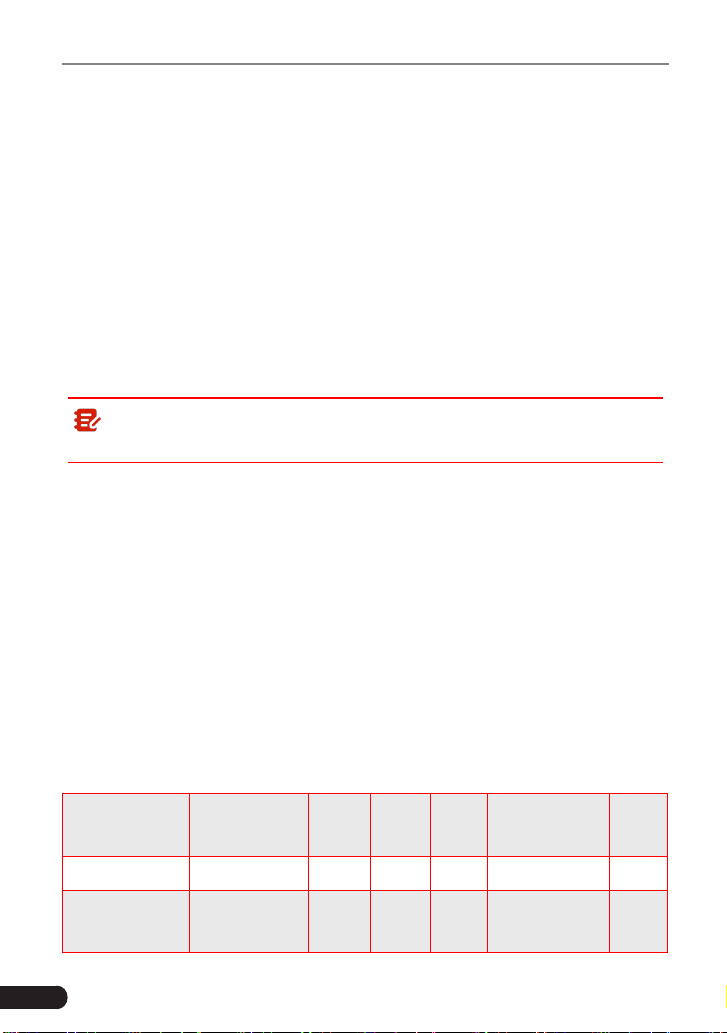
2.6.3 OBD II Reference Table
The table below lists current OBD II Monitors, and indicates the following for
each Monitor:
A. Monitor Type (how often does the Monitor run; Continuous or Once per trip).
B. Number of trips needed, with a fault present, to set a pending DTC.
C. Number of consecutive trips needed, with a fault present, to command the
MIL “On” and store a DTC.
D. Number of trips needed, with no faults present, to erase a Pending DTC.
E. Number and type of trips or drive cycles needed, with no faults present, to
turn o the MIL.
F. Number of warm-up periods needed to erase the DTC from the computer’s
memory after the MIL is turned o.
Name of
Monitor
A B C D E F
CCM Continuous 1 2 1 3 40
Misre Monitor
(Type 1 and 3)
Continuous 1 2 1
3 - similar
conditions
80

15
LAUNCH
TOUCH PRO ELITE User Manual
Misre Monitor
(Type 2)
Continuous 1 1 1
3 - similar
conditions
80
Fuel System
Monitor
Continuous 1 1 or 2 1
3 - similar
conditions
80
Catalytic
Converter
Monitor
Once per trip 1 2 1 3 trips 40
O
2
Sensor
Monitor
Once per trip 1 2 1 3 trips 40
O
2
Sensor
Heater Monitor
Once per trip 1 2 1 3 trips 40
EGR Monitor Once per trip 1 2 1 3 trips 40
EVAP system
Monitor
Once per trip 1 2 1 3 trips 40
Secondary Air
System
Monitor
Once per trip 1 2 1 3 trips 40
2.7 DTCs and MIL Status
When the vehicle’s on-board computer detects a failure in an emissions-related
component or system, the computer’s internal diagnostic program assigns a
diagnostic trouble code (DTC) that points to the system (and subsystem) where
the fault was found. The diagnostic program saves the code in the computer’s
memory. It records a “Freeze Frame” of conditions present when the fault was
found, and lights the Malfunction Indicator Lamp (MIL). Some faults require
detection for two trips in a row before the MIL is turned on.
Note: The “Malfunction Indicator Lamp” (MIL) is the accepted term used
to describe the lamp on the dashboard that lights to warn the driver that an
emissions-related fault has been found. Some manufacturers may still call
this lamp a “Check Engine” or “Service Engine Soon” light.
There are two types of DTCs used for emissions-related faults: Type “A” and
Type “B.” Type “A” codes are “One-Trip” codes; Type “B” DTCs are usually Two-

16
LAUNCH
TOUCH PRO ELITE User Manual
Trip DTCs.
When a
Type “A”
DTC is found on the First Trip, the following events take place:
• The computer commands the MIL “On” when the failure is rst found.
• If the failure causes a severe misre that may cause damage to the catalytic
converter, the MIL “ashes”
once per second
. The MIL continues to ash as
long as the condition exists. If the condition that caused the MIL to ash is no
longer present, the MIL will light “steady” On.
• A DTC is saved in the computer’s memory for later retrieval.
• A “Freeze Frame” of the conditions present in the engine or emissions system
when the MIL was ordered “On” is saved in the computer’s memory for later
retrieval. This information shows fuel system status (closed loop or open
loop), engine load, coolant temperature, fuel trim value, MAP vacuum, engine
RPM and DTC priority.
When a
Type “B”
DTC is found on the First Trip, the following events take place:
• The computer sets a Pending DTC, but the MIL is not ordered “On.”
“Freeze Frame” data may or may not be saved at this time depending on
manufacturer. The Pending DTC is saved in the computer’s memory for later
retrieval.
• If the failure is found on the second consecutive trip, the MIL is ordered “On.”
“Freeze Frame” data is saved in the computer’s memory.
• If the failure is not found on the second Trip, the Pending DTC is erased from
the computer’s memory.
The MIL will stay lit for both Type “A” and Type “B” codes until one of the
following conditions occurs:
• If the conditions that caused the MIL to light are no longer present for the
next three trips in a row, the computer automatically turns the MIL “O” if no
other emissions-related faults are present. However, the DTCs remain in the
computer’s memory as a history code for 40 warm-up cycles (80 warm-up
cycles for fuel and misre faults). The DTCs are automatically erased if the
fault that caused them to be set is not detected again during that period.
• Misfire and fuel system faults require three trips with “similar conditions”
before the MIL is turned “O.” These are trips where the engine load, RPM
and temperature are similar to the conditions present when the fault was rst
found.
Note: After turning o MIL, DTCs and Freeze Frame data will stay in
the computer’s memory.
• Erasing the DTCs from the computer’s memory can also turn o the MIL. If a

17
LAUNCH
TOUCH PRO ELITE User Manual
Diagnostic Tool or Scan Tool is used to erase the codes, Freeze Frame data
will also be erased.
18
LAUNCH
TOUCH PRO ELITE User Manual
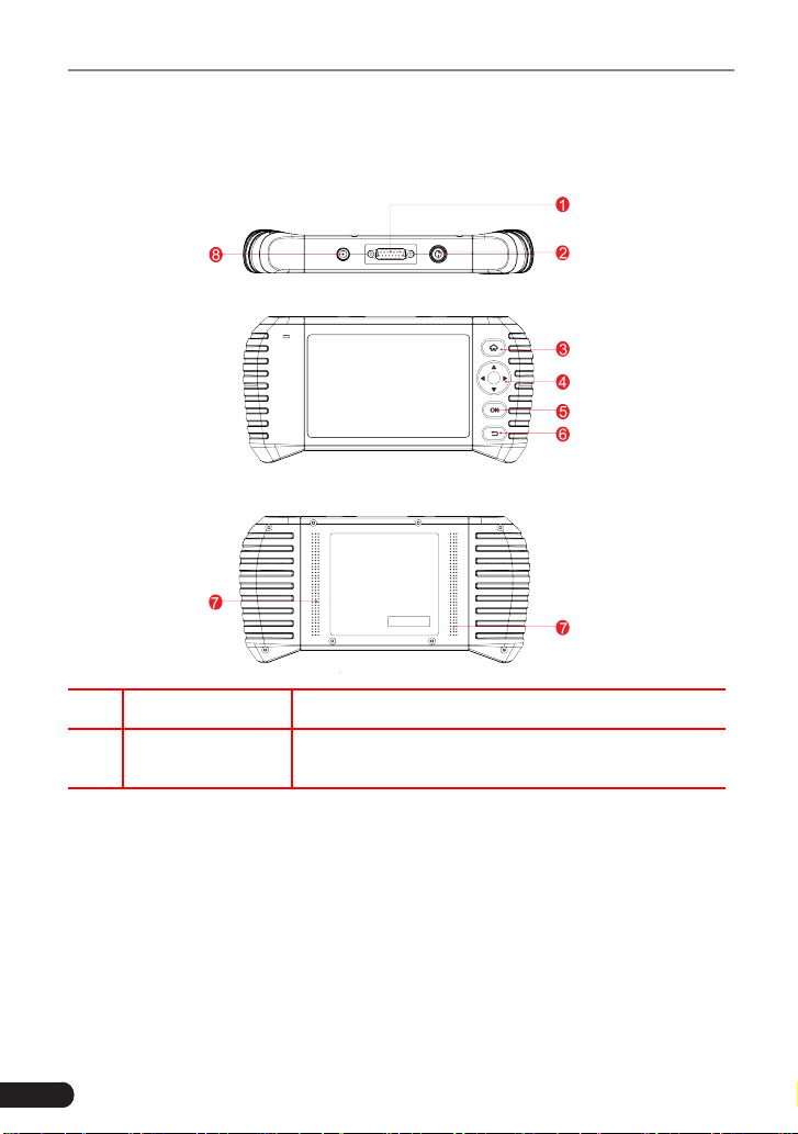
3. Components and Controls
3.1 Controls
NO. Name Descriptions
1
DB-15 Diagnostic
Connector
Connect to vehicle's DLC (Data Link Connector)
via diagnostic cable.
19
LAUNCH
TOUCH PRO ELITE User Manual
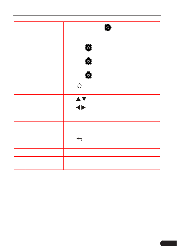
2 Power
• In O mode, press
button for about 5
seconds to turn on.
• In On mode:
• Press button to activate the LCD if the
LCD is o.
• Press
button to turn o the LCD if the
LCD lights up.
• Press
button for 3 seconds to turn o.
3 Home
Press
button to return to the home (Job menu)
screen.
4 Select
Move
/
button for up and down selection.
Move
/
button for left and right selection; Or
turn page up and down when more than one page
is displayed.
5 OK
Press
OK
button to conrm a selection (or action)
from a menu list.
6 Return
Press
button to exit the current program or
return to the previous screen.
7 Speakers Support sound play.
8
5 V DC Charging
Port
Connect to external DC power for charging the
tool.
3.2 Technical Specications
• Screen: 5” touch screen
• RAM: 2 GB
• ROM: 16 GB
• OBDII input voltage range: 9 to 18 V DC
• Touch & Keypad input
• Charging via:
• 5 V DC charging cable

20
LAUNCH
TOUCH PRO ELITE User Manual
• Diagnostic cable through connection to vehicle’s DLC
• Dimension: 245 x 123.5 x 36.8 mm
• Working temperature: -10 to 50 °C (14 to 122 F°)
• Storage temperature: -20 to 70 °C (-4 to 158 F°)
3.3 Accessory List
For detailed accessory items, please consult from the local agency.
1. TOUCH PRO ELITE handset
2. Diagnostic cable
3. 5 V DC charging cable
4. OBD II connector
5. European adapter kit
6. American adaptor
7. Handbag
8. Quick start guide
9. User manual
21
LAUNCH
TOUCH PRO ELITE User Manual
4. Initial Use
4.1 Charging the Tool
There are two charging methods available:
Via Charging Cable: Plug one end of the included charging cable into the DC-IN
port of the tool, and the other end to the external DC power.
Via Diagnostic Cable: Insert one end of the diagnostic cable into the DB-15
connector of the tool, and the other end to the vehicle’s DLC.
Once the charging LED illuminates solid green, it indicates that the battery is
fully charged.
4.2 Getting Started
If it is the first time you have used this tool, you need to make some system
settings.
1. Press the [Power] button to power it on.
2. The screen displays a welcome page. Tap “Start” to go to next step.
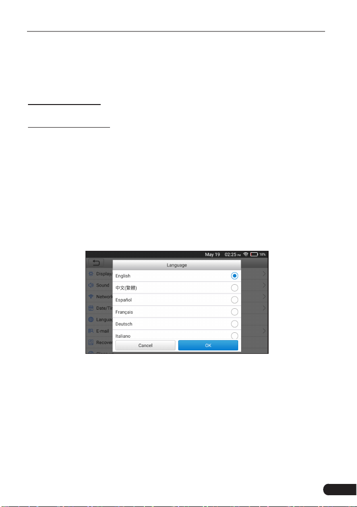
3. Choose the desired system language, and tap “OK” to conrm.
Figure 4-1
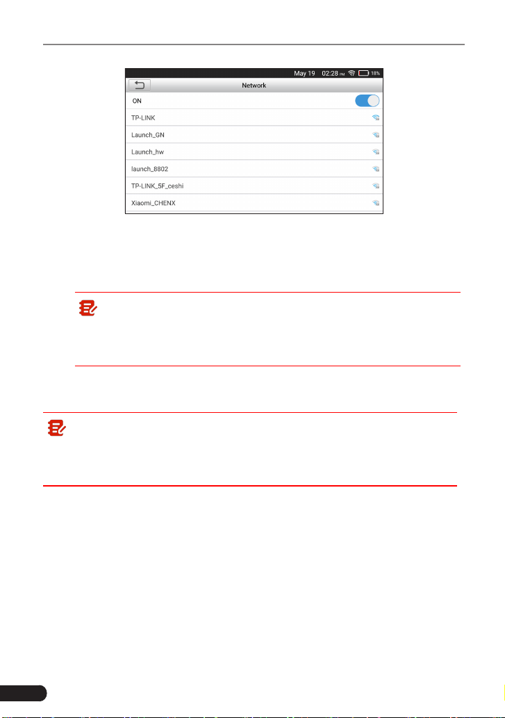
4. Choose the desired time zone, and tap “Next” to enter the WLAN setup page.
5. Slide the network switch to ON, the system starts searching for all available
wireless LANs. Choose the desired WLAN access point / network.
22
LAUNCH
TOUCH PRO ELITE User Manual
Figure 4-2
• If the network you chose is open, you can connect directly;
• If the selected network is encrypted, you have to enter the right security
key (network password).
Note: If you choose “Ignore” in WLAN setup, it will go into the date
setting page. If the tool has been properly connected to the Internet, the
system will automatically obtain the correct network date and time and
navigate to step 6.
6. After the network connection is done, tap “Next Step” to configure email
address. Input the email address, and tap “Next Step” to go to next step.
Note: You are strongly recommended to fill in the valid email address.
Once you configured this option, the system will automatically send the
diagnostic report to your email box every time a complete Auto-Detect
process is successfully nished.
7. Carefully read all terms and conditions of the user agreement, check the box
before the “Agree to all the above terms”, and tap “OK” finish the sign-up
process and navigate to Job Menu.
23
LAUNCH
TOUCH PRO ELITE User Manual
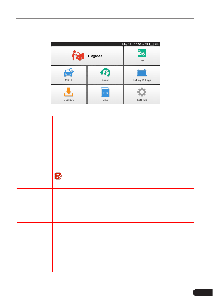
4.3 Job Menu
It mainly includes the following function modules.
Figure 4-3
Diagnose
To congures the tool to operate as a professional diagnostic
tool.
I/M
A quick access to the I/M Readiness function of OBD II
Diagnosis. I/M refers to Inspection and Maintenance that
is legislated by the Government to meet federal clean-air
standards. I/M Readiness indicates whether or not the various
emissions-related systems on the vehicle are operating
properly and are ready for Inspection and Maintenance testing.
Note: This function also can be done by performing "OBD II" ->
"I/M Readiness". For detailed operation, please refer to Chapter 5.3.
OBD II
This option presents a quick way to check for DTCs, isolate
the cause of the illuminated Malfunction Indicator Lamp (MIL),
check monitor status prior to emissions certification testing,
verify repairs, and perform a number of other services that are
emission-related.
Reset
To perform common repair & maintenance items, including Oil
Lamp Reset, Steering Angle Sensor (SAS) Reset, Electronic
Parking Brake (EPB), Battery Maintenance System (BMS) Re-
set, Diesel Particulate Filter (DPF), Electronic Throttle Position
Reset, ABS bleeding.
Battery
Voltage
Performs a check of the vehicle’s battery to ensure the system
is operating within acceptable limits.

24
LAUNCH
TOUCH PRO ELITE User Manual
Upgrade
To update vehicle diagnostic software and APK.
Note: This function requires a stable network connection.
Data
Includes Diagnostic report, Diagnostic record, Feedback and
DTC library etc.
Settings
To make some system settings, including Network setup,
Email and Brightness etc.
25
LAUNCH
TOUCH PRO ELITE User Manual
5. Diagnose
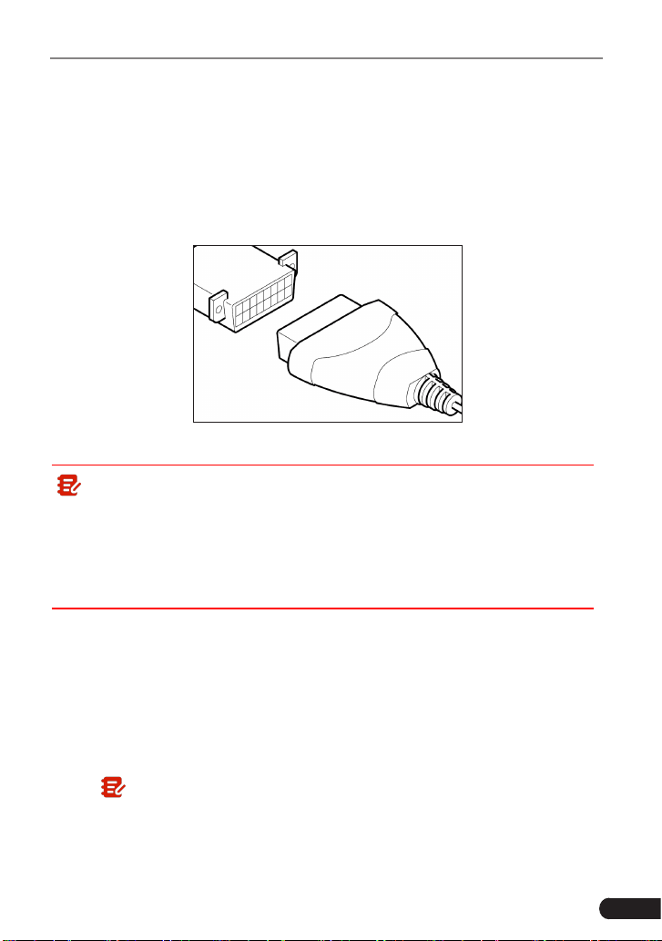
5.1 Connection
1. Turn the ignition o.
2. Locate vehicle’s DLC socket: Refer to Chapter 2.4 for DLC location.
3. Plug one end of the diagnostic cable into the DB-15 connector of the tool, and
tighten the captive screws. Connect the other end to the vehicle’s DLC.
Figure 5-1
Note:
• A plastic DLC cover may be found for some vehicles and you need to
remove it before plugging the diagnostic cable.
• The cable connector is keyed and will only fit one way. If you have
problems connecting the cable connector to the DLC, rotate the connector
180
0
and try again.
4. Turn the ignition on. Engine can be o or running.
5.2 System Diagnosing
This function is specially designed to diagnose electronic control systems of
single vehicle model.
5.2.1 Smart Diagnosis (Auto-Detect)
After connection, turn the ignition key on and the system enters auto-detect
mode (
Note: Please make sure the “Automac detecon on connect” in “Sengs”
is set as ON
).
26
LAUNCH
TOUCH PRO ELITE User Manual
Note: To detect more and accurate VINs, a stable network connection is
highly recommended for this function.
Caution: Don’t connect or disconnect any test equipment with ignition on
or engine running.
A. Once the system successfully obtains the VIN (Vehicle Identication Number)
information of the currently identified vehicle, it will continue scanning the
vehicle systems. After the scanning is complete, a diagnostic report will be
automatically generated and sent to your email box (if bound).
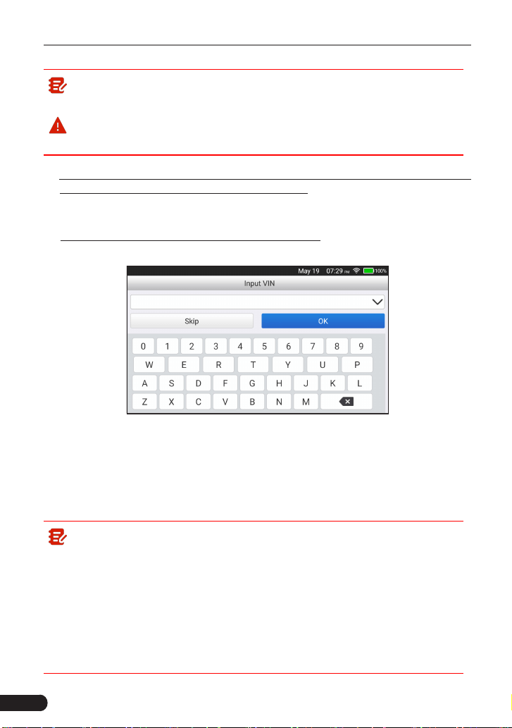
B. If the tool failed to access the VIN information, the screen will display as
below:
Fig. 5-2
Input the VIN, and tap “OK”, the system will automatically identify the vehicle
model. If the vehicle VIN is successfully decoded, it will perform auto-
diagnosis until a diagnostic report is automatically output. Otherwise it will
enter manual diagnosis mode. For details on manual diagnosis, see Chapter
5.2.2.
Note:
• The most recognizable location for this number is in the top left corner
on the vehicle’s dashboard. Other locations include the driver’s door or
post, and the rewall under the hood.
• In general, vehicle identication numbers are standardized - all contain
17 characters. VIN characters may be capital letters A through Z and
numbers 1 through 0; however, the letters I, O and Q are never used in
order to avoid mistakes of misreading. No signs or spaces are allowed
in the VIN.
27
LAUNCH
TOUCH PRO ELITE User Manual
5.2.2 Manual Diagnosis
If the tool can not obtain the VIN information, you can also perform vehicle
diagnosis manually. In this mode, you need to execute the menu-driven
command and then follow the on-screen instruction to proceed.
Note:
• Before diagnosing, please make sure the diagnostic program corresponding
to certain vehicle model has been installed on your tool.
• For vehicles manufactured by different vendors, it is possible that it has
dierent diagnostic menus. For details, please follow the instructions on the
screen to proceed.
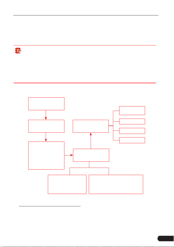
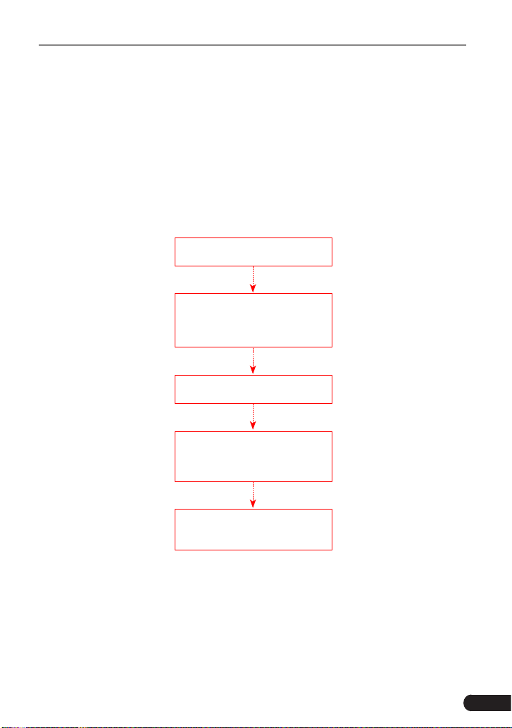
Refer to the owchart illustrated as below to diagnose a vehicle manually:
Select “Diagnose”
Automatic
(Note: This mode allows your
tool to scan the vehicle test
system automatically)
Manual Select
(Note: In this case, you need to choose the
desired system manually. Just follow the on-
screen instructions to proceed.)
Select test system
Select test function
Select Vehicle Model
(Note: For dierent vehicles,
vehicle make selection may
dier. Generally, we can
choose a vehicle via make
year. But for BENZ, we need
to choose it via chassis.)
Select Vehicle
Manufacturer
Read version
information
Read fault code
Clear fault code
Read data stream
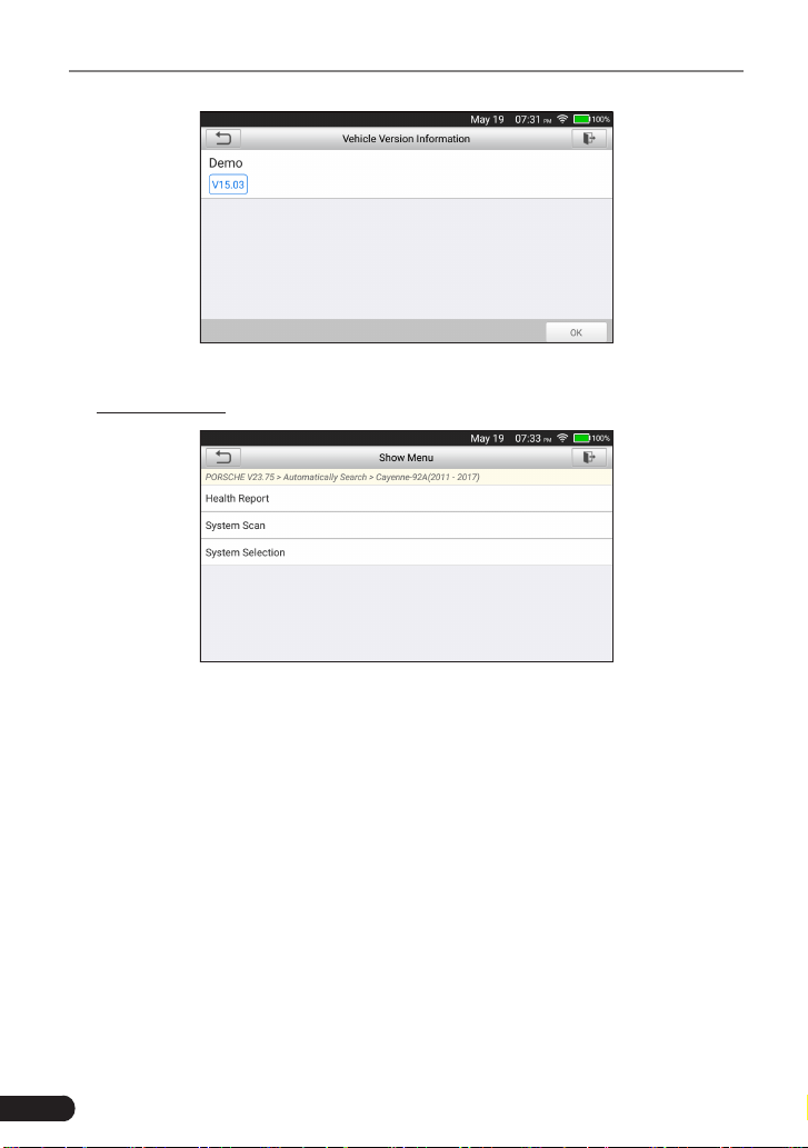
Take Demo as an example to demonstrate how to diagnose a vehicle.
1). Select diagnostic software version: Tap the “DEMO” , and then tap “OK“ to go
to Step 2.
28
LAUNCH
TOUCH PRO ELITE User Manual
Fig. 5-3
2). Select test item: Select the desired test item to proceed.
Fig. 5-4
5.2.2.1 Health Report (Quick Test)
This function varies depending on different vehicles applied. It enables you
to quickly access all the electronic control units of the vehicle and generate a
detailed report about vehicle health.
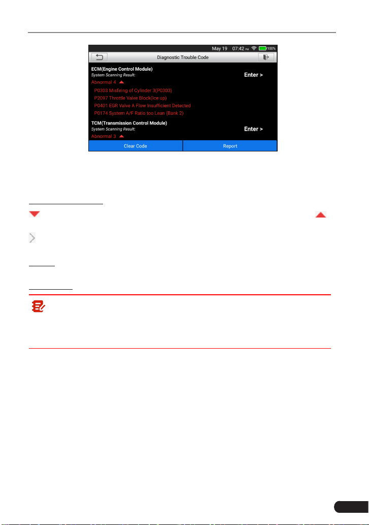
Tap “Health Report”, the system starts scanning the ECUs. Once the scanning is
complete, a screen similar to the following appears:
29
LAUNCH
TOUCH PRO ELITE User Manual
Fig. 5-5
In above gure, the tested system with fault code appears in red font and the
system without a fault code displays in green font.
On-screen Buttons:
: Tap to display the details of DTCs existing in the current system. Tap to
hide it.
: Tap to select other test functions. For detailed operations, refer to Chapter
5.2.2.3.
Report: Tap to save the diagnostic result as a report. All reports are saved under
the “Diagnostic Report” module in “Data”.
Clear Code: Tap to clear the existing diagnostic trouble codes.
Note: If you plan to take the vehicle to a Service Center for repair, DO
NOT erase the codes from the vehicle’s computer. If data is erased, valuable
information that might help the technician troubleshoot the problem will also
be erased.
5.2.2.2 System Scan
Use this option to quickly scan and identify which systems are installed on the
vehicle.
In Fig. 5-4, tap “System Scan” to scan the vehicle control modules. When
scanning is complete, tap the desired system to navigate to the test function
selection screen. For detailed operations on test function, please refer to Chapter
5.2.2.3.
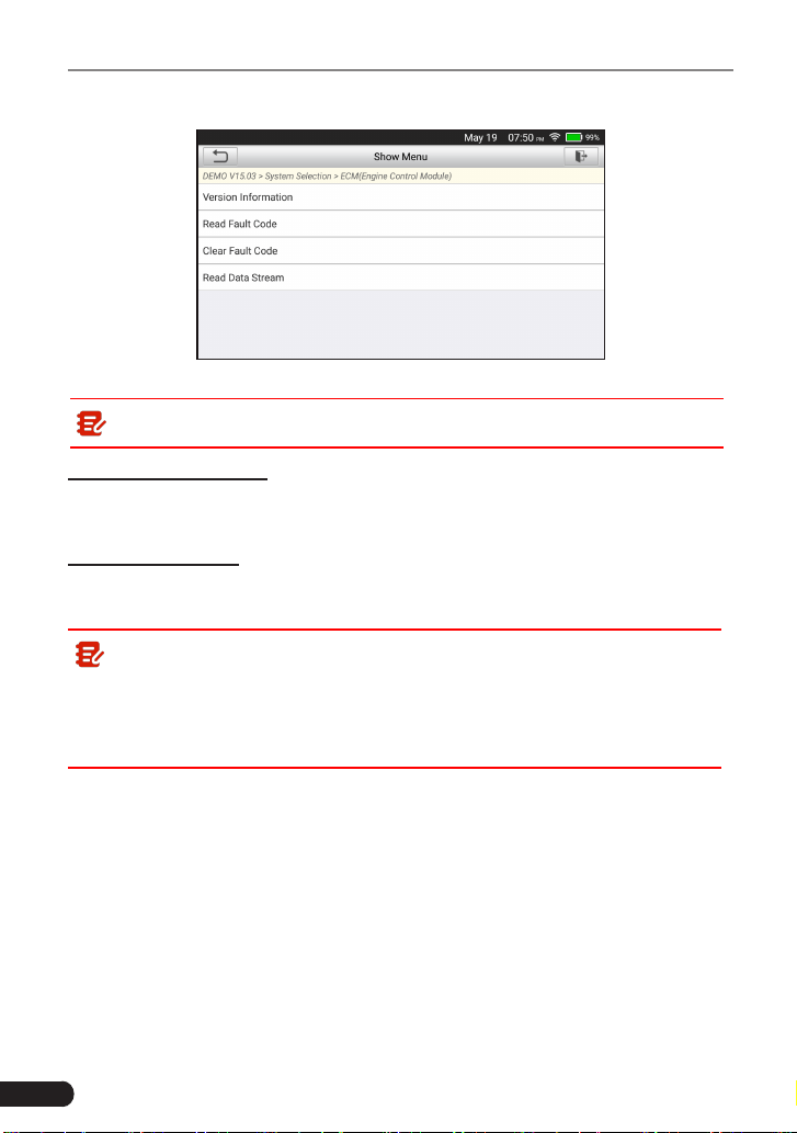
5.2.2.3 System Selection
This option allows you manually select the test system and function step by step.
In Fig. 5-4, tap “System Selection”, and tap the desired system (take “ECM” as
30
LAUNCH
TOUCH PRO ELITE User Manual
an example) to jump to the test function page.
Fig. 5-6
Note: Dierent vehicle has dierent diagnostic menus.
A. Version Information
This function is used to read the version information of system mode, vehicle
VIN, software and ECU.
B. Read Fault Code
This function displays the detailed information of DTC records retrieved from the
vehicle’s control system.
Note: Retrieving and using DTCs for troubleshooting vehicle operation is
only one part of an overall diagnostic strategy. Never replace a part based
only on the DTC definition. Each DTC has a set of testing procedures,
instructions and ow charts that must be followed to conrm the location of
the problem. This information can be found in the vehicle’s service manual.
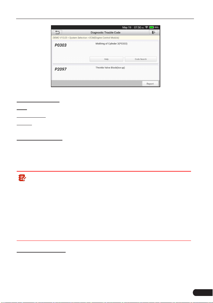
In Fig. 5-6, tap “Read Fault Code”, the screen will display the diagnostic result.
31
LAUNCH
TOUCH PRO ELITE User Manual
Fig. 5-7
On-screen Buttons:
Help: Tap to view the help information.
Code Search: Tap it to search for more information about the current DTC online.
Report: To save the current data in text format. All diagnostic reports can be
accessed from “Data” -> “Diagnostic Report”.
C. Clear Fault Code
After reading the retrieved codes from the vehicle and certain repairs have been
carried out, you can use this function to erase the codes from the vehicle. Before
performing this function, please be sure the vehicle’s ignition key is in the ON
position with the engine o.
Note:
1. If you plan to take the vehicle to a Service Center for repair, DO NOT
erase the codes from the vehicle’s computer. If data is erased, valuable
information that might help the technician troubleshoot the problem will also
be erased.
2. Clearing DTCs does not x the problem(s) that caused the code(s) to be
set. If proper repairs to correct the problem that caused the code(s) to be
set are not made, the code(s) will appear again and the check engine light
will illuminate as soon as the problem that cause the DTC to set manifests
itself.
D. Read Data Stream
This option retrieves and displays live data and parameters from the vehicle’s
ECU.
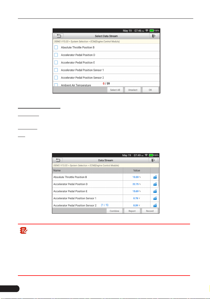
In Fig. 5-6, tap “Read Data Stream”, the system will display data stream items.
32
LAUNCH
TOUCH PRO ELITE User Manual
Fig. 5-8
On-screen Buttons:
Select All: Tap it to select all items of the current page. To select certain data
stream item, just check the box before the item name.
Unselect: Tap it to deselect all data stream items.
OK: Tap it to conrm and jump to the next step.
After selecting the desired items, tap “OK” to enter the data stream reading
page.
Fig. 5-9
Note:
1. If the value of the data stream item is out of the range of the standard
(reference) value, the whole line will display in red. If it complies with the
reference value, it displays in blue (normal mode).
2. The indicator 1/X shown on the bottom of the screen stands for the current
page/total page number. Swipe the screen from the right/left to advance/
return to the next/previous page.
33
LAUNCH
TOUCH PRO ELITE User Manual
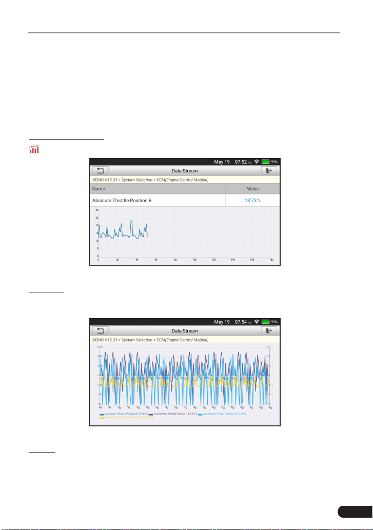
There are 3 types of display modes available for data viewing, allowing you to
view various types of parameters in the most suitable way.
• Value – this is the default mode which displays the parameters in texts and
shows in list format.
• Graph – displays the parameters in waveform graphs.
• Combine – this option is mostly used in graph merge status for data
comparison. In this case, dierent items are marked in dierent colors.
On-screen Buttons:
: Tap it to view the waveform graph of the current data stream item.
Fig. 5-10
Combine: Tap it, a list of the data stream items will appear on the screen. Select
the necessary items (Max. 4 items can be selected at the same time) and the
screen will display the waveforms corresponding to these items immediately.
Fig. 5-11
Report: Tap to save the current data as a diagnostic report. All diagnostic reports
can be accessed from
Data
->
Diagnostic Report
. The tool logs the Date of
Report (the date and time at which the report was created) and assigns a unique
Report #.
34
LAUNCH
TOUCH PRO ELITE User Manual
Record: Tap to record and save Live Data. Recorded Live Data can serve as
valuable information to help you in troubleshooting and diagnosing vehicle
problems. The saved le follows the naming rule: It begins with vehicle type, and
then the record starting time and ends with .x431 (To dierentiate between les,
please congure the accurate system time). All diagnostic records can be viewed
by tapping
Data
->
Diagnostic Record
.
5.3 OBDII Diagnosis
This option presents a quick way to check for DTCs, isolate the cause of the
illuminated Malfunction Indicator Lamp (MIL), check monitor status prior to
emissions certification testing, verify repairs, and perform a number of other
services that are emission-related.
After the tool is properly connected to the vehicle’s DLC, tap
OBD II
on the
Job menu. The tool will automatically start a check of the vehicle’s computer
to determine which type of communication protocol it is using. When the tool
identifies the computer’s communication protocol, a communication link is
established and then the screen will display the Monitor Status.
Fig. 5-12
Note: A PROTOCOL is a set of rules and procedures for regulating data
transmission between computers, and between testing equipment and
computers. Now ve dierent types of protocols (ISO 9141, Keyword 2000,
J1850 PWM, J1850 VPW and CAN) are in use by vehicle manufacturers.
Tap
OK
, the following function list appears.
1. Read Codes
This option is used to identify which section of the emission control system has
malfunctioned.

35
LAUNCH
TOUCH PRO ELITE User Manual
Note: Diagnostic Trouble Codes or Fault Codes can be used to identify
which engine systems or components that are malfunctioning. Never replace
a part based only on the DTC definition. Retrieving and using DTCs for
troubleshooting vehicle operation is only one part of an overall diagnostic
strategy. Follow testing procedures (in vehicle’s service manual), instructions
and owcharts to conrm the locations of the problem.
2. Erase Codes
After reading the retrieved codes from the vehicle and certain repairs have been
carried out, you can use this function to erase the codes from the vehicle. Before
performing this function, please be sure the vehicle’s ignition key is in the ON
position with the engine o.
Note:
• When this function is used to erase DTCs from the vehicle’s on-board
computer, “Freeze Frame” data is erased and “Permanent” DTCs ARE
NOT erased.
• When data is erased from the vehicle’s computer memory, the I/M
Readiness Monitor Status program resets the status of all Monitors to a
“Not Completed” status. To set all of the Monitors to a “Completed” status,
an OBD II Drive Cycle must be performed. Refer to your vehicle’s service
manual for information on how to perform an OBD II Drive Cycle for the
vehicle under test.
After clearing, you should retrieve trouble codes once more or turn ignition on
and retrieve codes again. If there are still some trouble codes in the system,
please troubleshoot the code using a factory diagnosis guide, then clear the
code and recheck.
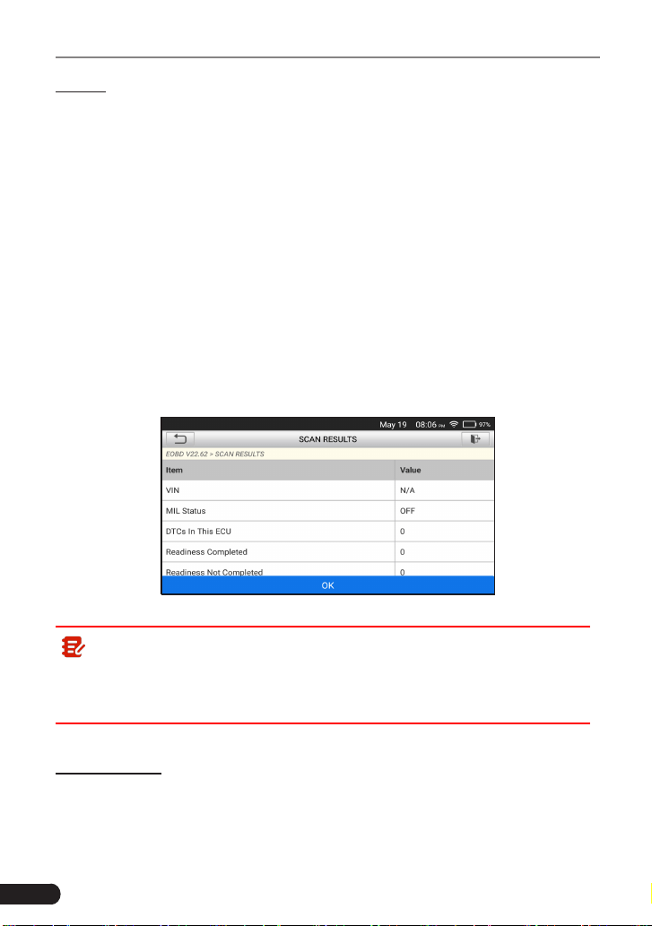
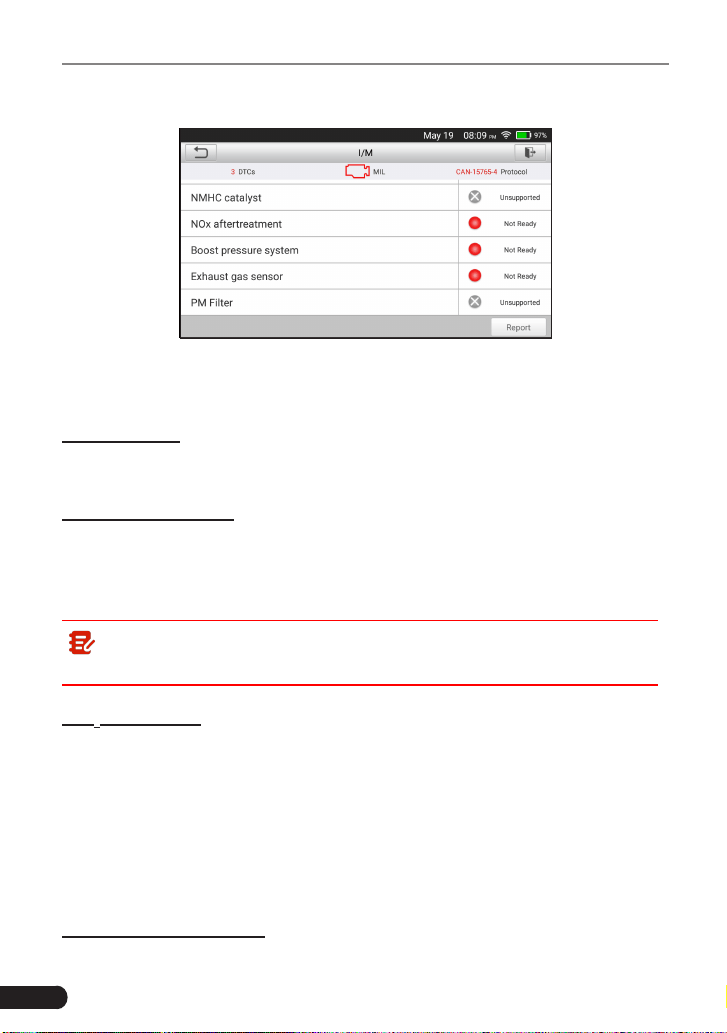
3. I/M Readiness
I/M refers to Inspection and Maintenance that is legislated by the Government
to meet federal clean-air standards. I/M Readiness indicates whether or not the
various emissions-related systems on the vehicle are operating properly and are
ready for Inspection and Maintenance testing.
The purpose of the I/M Readiness Monitor Status is to indicate which of the
vehicle’s Monitors have run and completed their diagnosis and testing, and
which ones have not yet run and completed testing and diagnosis of their
designated sections of the vehicle’s emissions system.
The I/M Readiness Monitor Status function also can be used (after repair of
a fault has been performed) to confirm that the repair has been performed
36
LAUNCH
TOUCH PRO ELITE User Manual
correctly, and/or to check for Monitor Run Status.
Fig. 5-13
This function can also be done by tapping [I/M Readiness] directly on the Job
Menu.
4. Data Stream
This option retrieves and displays live data and parameters from the vehicle’s
ECU.
5. View Freeze Frame
When an emission-related fault occurs, certain vehicle conditions are recorded
by the on-board computer. This information is referred to as freeze frame data.
Freeze Data is a snapshot of the operating conditions at the time of an emission-
related fault.
Note: If DTCs were erased, Freeze Data may not be stored in vehicle
memory depending on vehicle.
6. O
2
Sensor Test
OBD II regulations require that applicable vehicles monitor and test operation
of the oxygen (O
2
) sensors to identify problems that can affect fuel efficiency
and vehicle emissions. These tests are performed automatically when engine
operating conditions are within predefined limits. Results of these tests are
stored in the on-board computer’s memory.
The O
2
Sensor Test function lets you retrieve and view O
2
sensor monitor test
results for the most recently completed tests from your vehicle’s on-board
computer.
7. On-Board Monitor Test
37
LAUNCH
TOUCH PRO ELITE User Manual
The OBD Monitor Test function retrieves and displays test results for emission-
related powertrain components and systems that are not continuously monitored.
The tests available are determined by the vehicle manufacturer.
8. EVAP System Test
The EVAP test function lets you initiate a leak test for the vehicle’s EVAP
system. The tool does not perform the leak test, but signals to vehicle’s on-board
computer to initiate the test. Before using the system test function, refer to the
vehicle’s service repair manual to determine the procedures necessary to stop
the test.
9. Vehicle Info
This option displays the vehicle information. This information may include:
• VIN
(Vehicle identication Number). It is applicable to model year 2000 and
newer OBD II-compliant vehicles.
• CID
(Calibration ID). These IDs uniquely identify the software version(s) for
the vehicle’s control module(s).
• CVN
(Calibration Verification Number). CVNs are used to determine if
emission-related calibrations for the vehicle under test have been changed.
One or more CVNs may be returned by the vehicle’s computer.
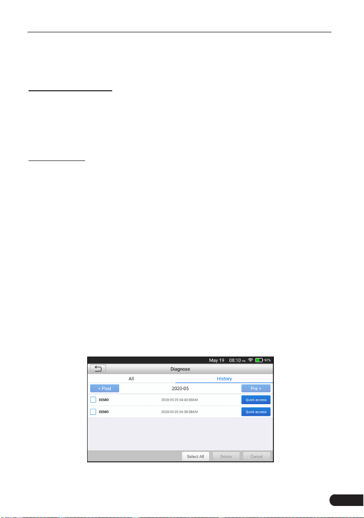
5.4 History
Generally once a vehicle diagnosis is performed, the tool will record the every
details of diagnostic session. The History function provides direct access to the
previously tested vehicles and users can resume from the last operation, without
the necessity of starting from scratch.
Tap “History” on the Manual Diagnosis main menu screen, all diagnostic records
will be listed on the screen in date sequence.
Fig. 5-13

38
LAUNCH
TOUCH PRO ELITE User Manual
• Tap certain vehicle model to view the details of the last diagnostic report.
• To delete certain diagnostic history, select it and then tap “Delete”. To delete
all historical records, tap “Select All” and then tap “Delete”.
• Tap “Quick access” to directly navigate to the function selection page of last
diagnostic operation. Choose the desired option to proceed.
39
LAUNCH
TOUCH PRO ELITE User Manual
5.5 Resetting
In addition to amazingly powerful diagnostic function, the product also features
Oil Lamp Reset, Steering Angle Sensor (SAS) Reset, Electronic Parking
Brake (EPB), Battery Maintenance System (BMS) Reset, Diesel Particulate
Filter (DPF), Electronic Throttle Position Reset, ABS bleeding and so on. The
reset service lamp function supports manual reseting and auto-resetting; Auto
resetting could send commands from the tool to the vehivle’s ECU, while manual
resetting enable users to operate following the on-screen instructions, users can
select appropriate excution options, or enter specic values, the system will also
guide users through the complete performance for various service operations.
Follow the owchart below to perform resetting.
Select "Reset"
Choose the desired service
function
(e.g. oil lamp reset
etc.)
Select the desired car brand
Select the reset mode
(The
available mode may dier due
to vehicle variations)
Follow the on-screen
instructions to proceed
5.5.1 Oil Lamp Reset
This function allows you to perform reset for the engine oil life system, which
calculates an optimal oil life change interval depending on the vehicle driving
conditions and climate.
This function can be performed in the following cases:
1. If the service lamp is on, you must provide service for the car. After service,

40
LAUNCH
TOUCH PRO ELITE User Manual
you need to reset the driving mileage or driving time so that the service lamp
turns o and the system enables the new service cycle.
2. After changing engine oil or electric appliances that monitor oil life, you need
to reset the service lamp.
5.5.2 Steering Angle Sensor Reset
To reset the steering angle, rst nd the relative zero point position for the car to
drive in straight line. Taking this position as reference, the ECU can calculate the
accurate angle for left and right steering.
After replacing the steering angle position sensor, replacing steering mechanical
parts (such as steering gearbox, steering column, end tie rod, steering knuckle),
performing four-wheel alignment, or recovering car body, you must reset the
steering angle.
5.5.3 Electronic Parking Brake Reset
1. If the brake pad wears the brake pad sense line, the brake pad sense line
sends a signal sense line to the on-board computer to replace the brake pad.
After replacing the brake pad, you must reset the brake pad. Otherwise, the
car alarms.
2. Reset must be performed in the following cases:
a) The brake pad and brake pad wear sensor are replaced.
b) The brake pad indicator lamp is on.
c) The brake pad sensor circuit is short, which is recovered.
d) The servo motor is replaced.
5.5.4 Battery Maintenance System Reset
This function enables you to perform a resetting operation on the monitoring
unit of vehicle battery, in which the original low battery fault information will be
cleared and battery matching will be done.
Battery matching must be performed in the following cases:
a) Main battery is replaced. Battery matching must be performed to clear original
low battery information and prevent the related control module from detecting
false information. If the related control module detects false information, it
will invalidate some electric auxiliary functions, such as automatic start &
stop function, sunroof without one-key trigger function, power window without
automatic function.
b) Battery monitoring sensor. Battery matching is performed to re-match the
control module and motoring sensor to detect battery power usage more

41
LAUNCH
TOUCH PRO ELITE User Manual
accurately, which can avoid an error message displaying on the instrument
panel.
5.5.5 Diesel Particulate Filter (DPF) Regeneration
DPF regeneration is used to clear PM (Particulate Matter) from the DPF filter
through continuous combustion oxidation mode (such as high temperature
heating combustion, fuel additive or catalyst reduce PM ignition combustion) to
stabilize the lter performance.
DPF regeneration may be performed in the following cases:
a) The exhaust back pressure sensor is replaced.
b) The PM trap is removed or replaced.
c) The fuel additive nozzle is removed or replaced.
d) The catalytic oxidizer is removed or replaced.
e) The DPF regeneration MIL is on and maintenance is performed.
f) The DPF regeneration control module is replaced.
5.5.6 Electronic Throttle Position Reset
This function enables you to make initial settings to throttle actuators and returns
the “learned” values stored on ECU to the default state. Doing so can accurately
control the actions of regulating throttle (or idle engine) to adjust the amount of
air intake.
5.5.7 ABS Bleeding
This function allows you to perform various bi-directional tests to check the
operating conditions of Anti-lock Braking System (ABS).
1. When the ABS contains air, the ABS bleeding function must be performed to
bleed the brake system to restore ABS brake sensitivity.
2. If the ABS computer, ABS pump, brake master cylinder, brake cylinder, brake
line, or brake uid is replaced, the ABS bleeding function must be performed
to bleed the ABS.

42
LAUNCH
TOUCH PRO ELITE User Manual
6. Update
If some new software or APK can be updated, a numeric indicator will display on
the “Upgrade” module on the Job menu. In this case, you may use this option to
keep it synchronized with the latest version.
Note:
• To enjoy more functions and better service, you are strongly suggested to
update it on regular basis.
• This function requires a stable network connection.
Tap “Upgrade” on the Job menu to enter the update center.
By default, all diagnostic software is selected.
To deselect certain software, tap “Unselect”, and then check the box next to
vehicle model.
Tap “Update” to start downloading. It may take several minutes to nish it, please
be patient to wait. To pause downloading, tap “Stop”. To resume it, tap “Continue”.
If network connection failure occurs, tap “Retry” to try again.
Once download is nished, the software packages will be installed automatically.
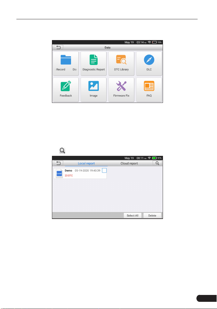
43
LAUNCH
TOUCH PRO ELITE User Manual
7. Data
Fig. 7-1
7.1 Diagnostic Report
This module stores all diagnostic reports saved on the Read Trouble Code
screen.
All the diagnostic reports are sorted by Date and Make. If there are too many
reports stored, tap (Search) to lter and quickly locate it.
Fig. 7-2
• To select all reports, tap “Select All”. To deselect all, tap “Unselect”.
• Tap it to view its details.
• Select the desired report and then tap “Delete” to delete it.
7.2 Diagnostic Record
If user records the running parameters or waveform graphs while reading data
stream, it will be saved as diagnostic records and appear under this module.
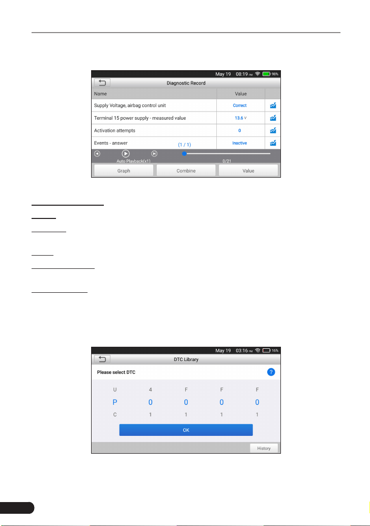
44
LAUNCH
TOUCH PRO ELITE User Manual
Tap “Diagnostic Record” to enter and select the desired data stream items and
tap “OK” to jump to the playback page.
Fig. 7-2
On-screen Buttons:
Graph – Displays parameters in waveform graphs.
Combine – Use to merge graphs for data comparison. Dierent items are coded
in dierent colors.
Value – The default mode displays the parameters as text in a list format.
Frame Playback – Use for frame-by-frame playback of the selected data stream
items. When in Frame Playback mode, this button changes to “Auto Playback”.
Auto Playback – Use for automatic playback of the selected data stream items.
When in Auto Playback mode, this button changes to “Frame Playback”.
7.3 DTC Library
This option helps you to nd the location of the vehicle’s DLC.
Fig. 7-3
Swipe the screen upwards/downwards to alter the value, then press [OK] button,

45
LAUNCH
TOUCH PRO ELITE User Manual
the screen will display denition of the DTC.
7.4 DLC(Data Link Connector) Location
This option helps you to nd the location of the vehicle’s DLC.
7.5 Feedback
This item allows you to feedback your diagnostic problems to us for analysis and
troubleshooting.
Tap “Feedback”, the following 3 options will be displayed on the left column of
the screen.
A. Diag. Feedback
Tap a tested vehicle model to enter the feedback screen.
1) Tap “Choose File” to open the target folder and choose the desired diagnostic
logs.
2) Choose the failure type and ll in the detailed failure description in the blank
text box and telephone or email address. After inputting, tap “Submit Result”
to send it to us.
B. History Feedback
Tap it to view all diagnostic feedback records. Different process states are
marked with dierent colors.
C. Oine Feedback
Tap it to display all diagnostic feedback logs which have not been submitted
successfully due to network failure. Once the handset gets a stable network
signal, it will be uploaded to the remote server automatically.
7.6 Firmware Fix
Use this item to upgrade and x diagnostic rmware. During xing, please do not
cut power or switch to other interfaces.
7.7 FAQ
Provides some frequently asked questions of the tool.
7.8 Image
All screenshots created during vehicle diagnosis are saved in this module. To
enable the screenshot function, go to Settings and slide the Screen capture
switch to ON. A screenshot icon will oat on upper right corner of the screen.

46
LAUNCH
TOUCH PRO ELITE User Manual
8. Settings
8.1 Units of Measurement
It is designed to set the measurement unit. Metric System and English System
are available.
8.2 Screen Capture
This option allows you to capture the current screen. All screenshots created
during vehicle diagnosis are saved in “Data” -> “Image” module.
To enable the screenshot function, slide the Screen capture switch to ON. A
screenshot icon will oat on upper right corner of the screen. Tap it to capture
the screen.
8.3 Automatic Detection on Connect
This option enables you to determine whether to start an automatic VIN detection
once the tool is properly connected to the vehicle’s DLC.
8.4 Display & Brightness
This item allows you to set the standby time and screen brightness.
Tips: Reducing the brightness of the screen is helpful to conserve the
power of the handset.
8.5 Sound
This option lets you adjust the volume and other sound settings.
8.6 Network
Note: Once WLAN is set as ON, the tool will consume more power. While
it keeps unused, please set it o to save power. While WLAN keeps unused,
please turn it o to conserve battery power.
The tool has built-in WLAN module that can be used to get online. Once you’re
online, you can register your tool, update diagnostic software & APK, send email
on your network.
Slide the switch to ON, the system starts searching for all available wireless
LANs. Choose the desired WLAN access point / network to connect.
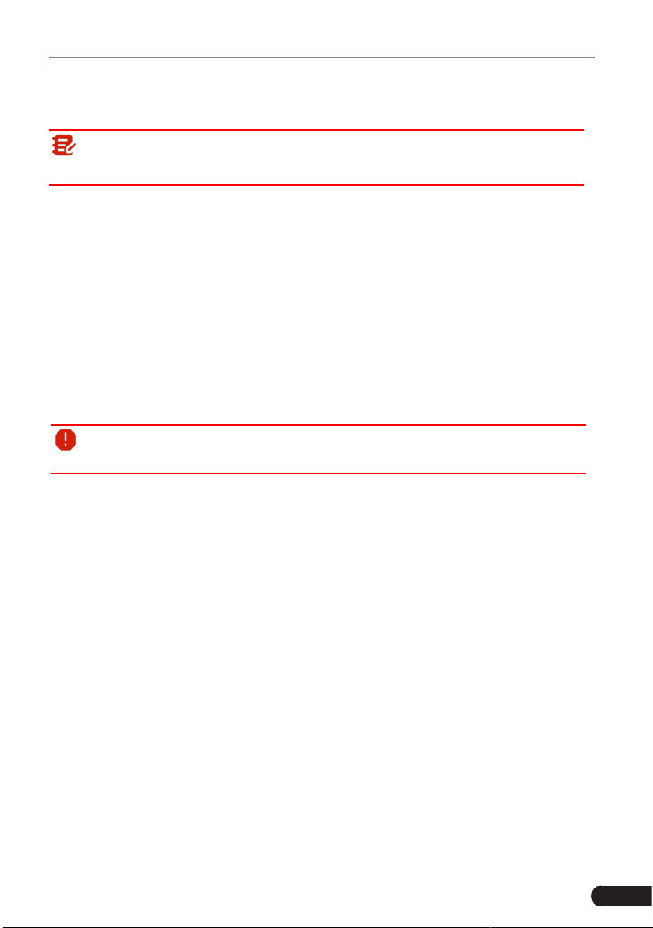
47
LAUNCH
TOUCH PRO ELITE User Manual
8.7 Date/Time
This option allows you to set the system date & time.
Note: Since all diagnostic reports are sorted by Make and Date. To
dierentiate between les, please congure the accurate system time.
8.8 Language
The tool supports multiple languages. You can use this option to change the
target language.
8.9 Email Setup
This option is used to set up the default email address for automatically receiving
the diagnostic reports.
8.10 Recovery
Use this item to reset this tool to the default factory setting.
Warning: Resetting may cause data loss. Before doing so, please be
careful to perform this operation.
8.11 Clean up
This option allows user to clear some cache files and free up some storage
space.
8.12 About
This option displays the hardware configuration information of the tool and
license agreement.
48
LAUNCH
TOUCH PRO ELITE User Manual
9. FAQ
Here we list some frequently asked questions and answers related to this tool.
System halts when reading data stream. What is the reason?
It may be caused by a slackened connector. Please turn this tool off, firmly
connect the connector, and switch it on again.
Screen of main unit ashes at engine ignition start.
Caused by electromagnetic disturbing, and this is normal phenomenon.
There is no response when communicating with on-board computer.
Please confirm the proper voltage of power supply and check if the throttle
has been closed, the transmission is in the neutral position, and the water is in
proper temperature.
What to do if the system fails to start auto VIN detection?
Please check the following possible reasons:
• Whether the tool is properly connected to the vehicle’s DLC.
• Whether the “Automatic detection on Connect” switch is OFF. If yes, slide it to
ON.
Why are there so many fault codes?
Usually, it’s caused by poor connection or fault circuit grounding.
How to upgrade the system software?
1. Switch the tool on and ensure a stable internet connection.
2. Tap “Setting” on the Job Menu, select “About” -> “Version”, and tap “Detect the
System Version” to enter the system upgrading page.
3. Follow the on-screen instructions step by step to finish the process. It may
take several minutes depending on the internet speed, please be patient. After
upgrade is successfully nished, the tool will automatically restart and enters
the Job menu.
What if the tool cannot be switched on even after a period of recharging?

49
LAUNCH
TOUCH PRO ELITE User Manual
Please recharge it for at least 3 hours until the power LED lights up, then it can
be switched on.

50
LAUNCH
TOUCH PRO ELITE User Manual
Warranty
THIS WARRANTY IS EXPRESSLY LIMITED TO PERSONS WHO PURCHASE
LAUNCH PRODUCTS FOR PURPOSES OF RESALE OR USE IN THE
ORDINARY COURSE OF THE BUYER’S BUSINESS.
LAUNCH electronic product is warranted against defects in materials and
workmanship for one year (12 months) from date of delivery to the user.
This warranty does not cover any part that has been abused, altered, used for a
purpose other than for which it was intended, or used in a manner inconsistent
with instructions regarding use. The exclusive remedy for any automotive meter
found to be defective is repair or replacement, and LAUNCH shall not be liable
for any consequential or incidental damages.
Final determination of defects shall be made by LAUNCH in accordance with
procedures established by LAUNCH. No agent, employee, or representative of
LAUNCH has any authority to bind LAUNCH to any armation, representation,
or warranty concerning LAUNCH automotive meters, except as stated herein.
Order Information
Replaceable and optional parts can be ordered directly from your LAUNCH
authorized tool supplier. Your order should include the following information:
1. Quantity
2. Part number
3. Item description
Customer Service
If you have any questions on the operation of the unit, please contact local
dealer, or contact LAUNCH TECH CO., LTD.:
Website: www.x431.com
www.cnlaunch.com
Phone: +86 755 8455 7891
Email: [email protected]
Statement: LAUNCH reserves the rights to make any change to this manual without
notice. We have tried our best to make the descriptions and illustrations in the
manual as accurate as possible, and defects are inevitable, if you have any queson,
please contact local dealer or LAUNCH TECH. CO., LTD., LAUNCH does not bear any
responsibility arising from misunderstandings.