Loading ...
Loading ...
Loading ...
W415-1476 / A / 09.30.16
21
EN
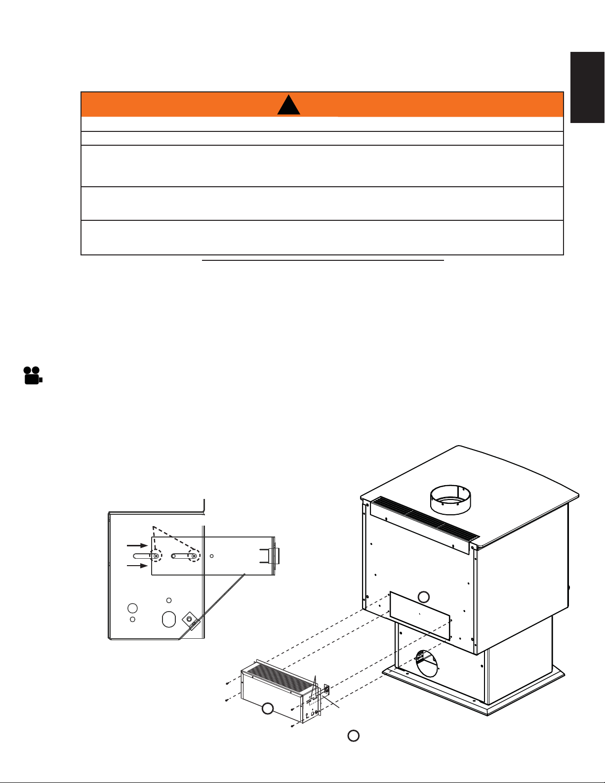
KNOCK-OUT
BLOWER
C
D
B
THERMAL DISC
BRACKET
SCREWS
Provisions have been made on the stove to install an optional blower kit (EP65) that comes complete with a
variable speed switch to turn the blower on and off, as well as adjusting the blower speed and a thermostatic
sensor to thermally activate the blower.
Drywall dust will penetrate into the blower bearings, causing irreparable damage. Care must be taken to
prevent drywall dust from coming into contact with the blower or its compartment. Any damage resulting from
this condition is not covered by the warranty policy.
Use of the blower increases the output of heat.
A. Ensure the thermal disc bracket is in the correct position, refer to Figure 1.
B. Remove the knock-out from the back of the appliance.
C. Install the blower and housing as shown using the 4 screws supplied, refer to Figure 2.
D. Loosen the thermal disc bracket (2 screws) and slide
the bracket until the thermal disc is touching the rear
of the fi rebox and secure.
Fig. 2
6.0 OPTIONAL KIT INSTALLATIONS
6.1 BLOWER KIT INSTALLATION
!
WARNING
RISK OF FIRE AND ELECTRICAL SHOCK.
TURN OFF THE GAS AND ELECTRICAL POWER BEFORE SERVICING THIS APPLIANCE.
USE ONLY WOLF STEEL APPROVED OPTIONAL ACCESSORIES AND REPLACEMENT PARTS WITH
THIS APPLIANCE. USING NON-LISTED ACCESSORIES (BLOWERS, DOORS, LOUVRES, TRIMS, GAS
COMPONENTS, VENTING COMPONENTS, ETC.) COULD RESULT IN A SAFETY HAZARD AND WILL
VOID THE WARRANTY AND CERTIFICATION.
ENSURE THAT THE FAN’S POWER CORD IS NOT IN CONTACT WITH ANY SURFACE OF THE
APPLIANCE TO PREVENT ELECTRICAL SHOCK OR FIRE DAMAGE. DO NOT RUN THE POWER
CORD BENEATH THE APPLIANCE.
THE WIRE HARNESS PROVIDED IN THE BLOWER KIT IS A UNIVERSAL HARNESS. WHEN
INSTALLED, ENSURE THAT ANY EXCESS WIRE IS CONTAINED, PREVENTING IT FROM MAKING
CONTACT WITH MOVING OR HOT OBJECTS.
51.5
TURN OFF THE ELECTRICAL POWER BEFORE SERVICING THIS APPLIANCE.
THERMAL DISC BRACKET
Fig. 1
6.1.1 BLOWER INSTALLATION
Loading ...
Loading ...
Loading ...