INSTALLATION
INSTRUCTIONS
Models
EBP
EBX
Use ONLY factory listed electric heaters.
Fan Coils
General Information / Installation ....... 2
Upflow Installations ................... 3
Downflow Installations ................ 3
Horizontal Installations ................ 3
Ductwork Connections ................ 4
Electrical Connections ................. 5
Diagrams ............................. 6
Transformer Information ............... 7
Refrigerant Tubing .................... 8
Refrigerant Flow Control ............... 8
Condensate Drains .................... 9
Condensate Drain Diagrams ........... 10
Start-Up Procedures .................. 11
Safety Labeling and Signal Words
Danger, Warning and Caution
The signal words DANGER, WARNING and CAU-
TION are used to identify levels of hazard seriousness.
The signal word DANGER is only used on product la-
bels to signify an immediate hazard. The signal words
WARNING and CAUTION will be used on product la-
bels and throughout this manual and other manuals that
may apply to the product.
DANGER - Immediate hazards which WILL result in
severe personal injury or death.
WARNING - Hazards or unsafe practices which
COULD result in severe personal injury or death.
CAUTION - Hazards or unsafe practices which
COULD result in minor personal injury or product or
property damage.
Signal Words in Manuals
The signal word WARNING is used throughout this
manual in the following manner:
The signal word CAUTION is used throughout this
manual in the following manner:
CAUTION
Product Labeling
Signal words are used in combination with colors and/or
pictures on product labels.
Printed in U.S.A. 496 01 4112 01
Jan. 2003
I Installation Instructions Fan Coils I
Figure 1
I Clearances
OutEet Air
Hnlet Air
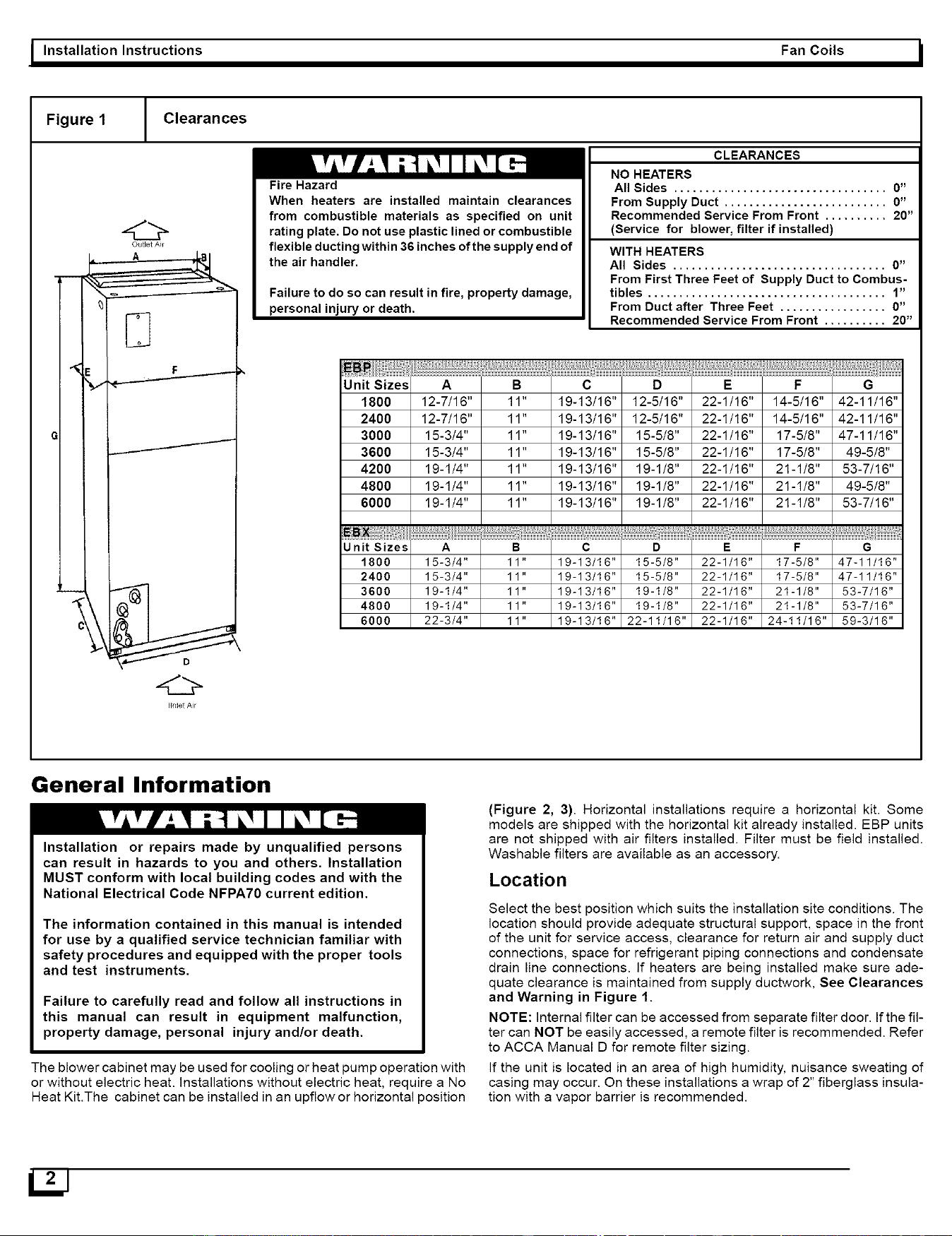
Fire Hazard
When heaters are installed maintain clearances
from combustible materials as specified on unit
rating plate. Do not use plastic lined or combustible
flexible ducting within 36 inches of the supply end of
the air handler.
Failure to do so can result in fire, property damage,
personal injury or death.
CLEARANCES
NO HEATERS
All Sides .................................. 0"
From Supply Duct .......................... 0"
Recommended Service From Front .......... 20"
(Service for blower, filter if installed)
WITH HEATERS
All Sides .................................. 0"
From First Three Feet of Supply Duct to Combus-
tibles ...................................... 1"
From Duct after Three Feet ................. 0"
Recommended Service From Front .......... 20"
Unit Sizes
1800
2400
3000
3600
4200
4800
6000
Unit Sizes
1800
2400
3600
4800
6000
A
12-7/16"
12-7/16"
15-3/4"
15-3/4"
19-1/4"
19-1/4"
19-1/4"
B
11"
11"
11"
11"
11"
11"
11"
C
19-13/16"
19-13/16"
19-13/16"
19-13/16"
19-13/16"
19-13/16"
19-13/16"
D
12-5/16"
12-5/16"
15-5/8"
15-5/8"
19-1/8"
19-1/8"
19-1/8"
E
22-1/16"
22-1/16"
22-1/16"
22-1/16"
22-1/16"
22-1/16"
22-1/16"
F
14-5/16"
14-5/16"
17-5/8"
17-5/8"
21-1/8"
21-1/8"
21-1/8"
A B C D E F
15-3/4" 11" 19-13/16" 15-5/8" 22-1/16" 17-5/8"
15-3/4" 11" 19-13/16" 15-5/8" 22-1/16" 17-5/8"
19-1/4" 11" 19-13/16" 19-1/8" 22-1/16" 21-1/8"
19-1/4" 11" 19-13/16" 19-1/8" 22-1/16" 21-1/8"
22-3/4" 11" 19-13/16" 22-11/16" 22-1/16" 24-11/16"
G
42-11/16"
42-11/16"
47-11/16"
49-5/8"
53-7/16"
49-5/8"
53-7/16"
G
47-11/16"
47-11/16"
53-7/16"
53-7/16"
59-3/16"
General Information
Installation or repairs made by unqualified persons
can result in hazards to you and others. Installation
MUST conform with local building codes and with the
National Electrical Code NFPA70 current edition.
The information contained in this manual is intended
for use by a qualified service technician familiar with
safety procedures and equipped with the proper tools
and test instruments,
Failure to carefully read and follow all instructions in
this manual can result in equipment malfunction,
property damage, personal injury and/or death.
The blower cabinet may be used for cooling or heat pump operation with
or without electric heat. Installations without electric heat, require a No
Heat Kit.The cabinet can be installed in an upflow or horizontal position
(Figure 2, 3). Horizontal installations require a horizontal kit. Some
models are shipped with the horizontal kit already installed. EBP units
are not shipped with air filters installed. Filter must be field installed.
Washable filters are available as an accessory.
Location
Select the best position which suits the installation site conditions. The
location should provide adequate structural support, space in the front
of the unit for service access, clearance for return air and supply duct
connections, space for refrigerant piping connections and condensate
drain line connections. If heaters are being installed make sure ade-
quate clearance is maintained from supply ductwork, See Clearances
and Warning in Figure 1.
NOTE: Internal filter can be accessed from separate filter door. If the fil-
ter can NOT be easily accessed, a remote filter is recommended. Refer
to ACCA Manual D for remote filter sizing.
If the unit is located in an area of high humidity, nuisance sweating of
casing may occur. On these installations a wrap of 2" fiberglass insula-
tion with a vapor barrier is recommended.
UJ
I Fan Coils Installation Instructions I
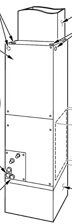
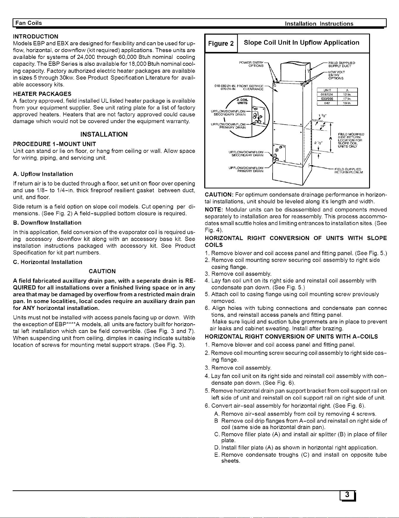
Figure 2 Slope Coil Unit In Upflow Application
INTRODUCTION
Models EBP and EBX are designed for flexibility and can be used for up-
flow, horizontal, or downflow (kit required) applications. These units are
available for systems of 24,000 through 60,000 Btuh nominal cooling
capacity. The EBP Series is also available for 18,000 Btuh nominal cool-
ing capacity. Factory authorized electric heater packages are available
in sizes 5 through 30kw. See Product Specification Literature for avail-
able accessory kits.
HEATER PACKAGES
A factory approved, field installed UL listed heater package is available
from your equipment supplier. See unit rating plate for a list of factory
approved heaters. Heaters that are not factory approved could cause
damage which would not be covered under the equipment warranty.
INSTALLATION
PROCEDURE 1-MOUNT UNIT
Unit can stand or lie on floor, or hang from ceiling or wail. Allow space
for wiring, piping, and servicing unit.
A. Upflow Installation
If return air is to be ducted through a floor, set unit on floor over opening
and use 1/8- to 1/4-in. thick fireproof resilient gasket between duct,
unit, and floor.
Side return is a field option on slope coil models. Cut opening per di-
mensions. (See Fig. 2) A field-supplied bottom closure is required.
B. Downflow Installation
In this application, field conversion of the evaporator coil is required us-
ing accessory downflow kit along with an accessory base kit. See
installation instructions packaged with accessory kit. See Product
Specification for kit part numbers.
C. Horizontal Installation
CAUTION
A field fabricated auxiliary drain pan, with a seperate drain is RE-
QUIRED for all installations over a finished living space or in any
area that may be damaged by overflow from a restricted main drain
pan. In some localities, local codes require an auxiliary drain pan
for ANY horizontal installation.
Units must not be installed with access panels facing up or down. With
the exception of EBP .... A models, all units are factory built for horizon-
tal left installation which can be field convertible. (See Fig. 3 and 7).
When suspending unit from ceiling, dimples in casing indicate suitable
location of screws for mounting metal support straps. (See Fig. 3).
018-06021 IN, FRONT SERVICE
070 24-1N CLEARANCE
UPFLOW/DOWNFLOW
SUPPLY DUCT
ENTRY
OPTIONS
UNIT A
018#O24 12 In.
042 19 In
030/036 17 In.
½"
FIELD MODIFIED
A SIDE RETURN
LOCATION FOR
SLOPE COIL
UNITS ONLY
CAUTION: For optimum condensate drainage performance in horizon-
tal installations, unit should be leveled along it's length and width.
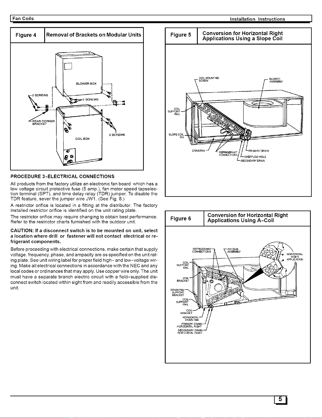
NOTE: Modular units can be disassembled and components moved
separately to installation area for reassembly. This process accommo-
dates small scuttle holes and limiting entrances to installation sites. (See
Fig. 4).
HORIZONTAL RIGHT CONVERSION OF UNITS WITH SLOPE
COILS
1. Remove blower and coil access panel and fitting panel. (See Fig. 5.)
2. Remove coil mounting screw securing coil assembly to right side
casing flange.
3. Remove coil assembly.
4. Lay fan coil unit on its right side and reinstall coil assembly with
condensate pan down. (See Fig. 5.)
5. Attach coil to casing flange using coil mounting screw previously
removed.
6. Align holes with tubing connections and condensate pan connec
tions, and reinstall access panels and fitting panel.
Make sure liquid and suction tube grommets are in place to prevent
air leaks and cabinet sweating. Install after brazing.
HORIZONTAL RIGHT CONVERSION OF UNITS WITH A-COILS
1. Remove blower and coil access panel and fitting panel.
2. Remove coil mounting screw securing coil assembly to right side cas-
ing flange.
3. Remove coil assembly.
4. Lay fan coil unit on its right side and reinstall coil assembly with con-
densate pan down. (See Fig. 6).
5. Remove horizontal drain pan support bracket from coil support rail on
left side of unit and reinstall on coil support rail on right side of unit.
6. Convert air-seal assembly for horizontal right. (See Fig. 6).
A. Remove air-seal assembly from coil by removing 4 screws.
B Remove coil drip flanges from A-coil and reinstall on right side of
coil (same side as horizontal drain pan).
C. Remove filler plate (A) and install air splitter (B) in place of filler
plate.
D. Install filler plate (A) as shown in horizontal right application.
E. Remove condensate troughs (C) and install on opposite tube
sheets.
HJJ

I Installation Instructions Fan Coils I
F. Install hose onto plastic spout.
7. Install horizontal pan on right side of coi! assembly.
8. Slide coil assembly into casing. Be sure coil bracket on each corner
of vertical pan engages coil support rails.
9. Reinstall 2 snap-in clips to correctly position and secure coil assem-
bly in unit. Be sure clip with large offsets is used on right side of unit
to secure horizontal pan.
10. Remove 2 oval coil access panel plugs and reinstall into holes on left
side of coil access panel and fitting panel.
11. Remove insulation knockouts on right side of coil access panel
12. Reinstall access fitting panels, aligning holes with tubing connec-
tions and condensate pan connections. Be sure to reinstall metal
clip between fitting panel and vertical condensate pan.
Make sure liquid and suction tube grommets are in place to prevent air
leaks and cabinet sweating.
D. Manufactured and Mobile Home Housing Applications
1. Fan coil unit must be secured to the structure using field-supplied
hardware.
2. Allow a minimum of 24" clearance from access panels.
3. Recommended method of securing for typical applications
a. If fan coil is away from wall, attach pipe strap to top of fan coil
using No. 10 self tapping screws. Angle strap down and away
from back of fan coil, remove all slack, and fasten to wall stud of
Figure 3
structure using 5/16-in. lag screws. Typically both sides of fan
coil.
b. If fan coil is against wall, secure fan coil to wall stud using
1/8-in. thick right-angle brackets. Attach brackets to fan coil us
ing No. 10 self tapping screws and to wall stud using 5/16-in. lag
screws. (See Fig. 9).
PROCEDURE 2-AIR DUCTS
Connect supply-air duct over the outside of 3/4-in. flanges provided on
supply-air opening. Secure duct to flange, using proper fasteners for
type of duct used, and seal duct-to-unit joint. If return-air flanges are
required, install factory authorized accessory kit.
Use flexible connectors between ductwork and unit to prevent transmis-
sion of vibration. When electric heater is installed, use heat-resistant
material for flexible connector between ductwork and unit at discharge
connection. Ductwork passing through unconditioned space must be in-
sulated and covered with vapor barrier.
Ductwork Acoustical Treatment
Metal duct systems that do not have a 90 degree elbow and 10 ft. of main
duct to first branch takeoff may require internal acoustical insulation lin-
ing. As an alternative, fibrous ductwork may be used if constructed and
installed in accordance with the latest edition of SMACNA construction
standard on fibrous glass ducts. Both acoustical lining and fibrous duct-
work shall comply with National Fire Protection Association as tested by
UL Standard 181 for Class 1 air ducts.
Slope Coil In Horizontal Left Application
LOW VOLT
ENTRY
OPTIONS
1_ 'PRIMARY
FIELD DRAIN
018-060 21 -IN.
If" II .
/Ifr ...... II II CLEARANCE
11II _"- -_ I I II, (FULL FACE
'k",,llt 1 -,"_ _.11 FILTERACOESS
..... SEOO 2 RyDRA,. '
POWER DRAIN
ENTRY OPTIONS
I Fan Coils
Figure 4
Removal of Brackets on Modular Units
r
_-2SCREWSI_"_I
k",,. , scREws
_REAR CORNER "_ _-'_L
2 SCREWS
COiL BOX
PROCEDURE3-ELECTRICALCONNECTIONS
All products from the factory utilize an electronic fan board which has a
low voltage circuit protective fuse (5 amp.), fan motor speed tapselec-
tion terminal (SPT), and time delay relay (TDR) jumper. To disable the
TDR feature, sever the jumper wire JW1. (See Fig. 8.)
A restrictor orifice is located in a fitting at the distributor. The factory
installed restrictor orifice is identified on the unit rating plate.
The restrictor orifice may require changing to obtain best performance.
Refer to the restrictor charts furnished with the outdoor unit.
CAUTION: If a disconnect switch is to be mounted on unit, select
a location where drill or fastener will not contact electrical or re-
frigerant components,
Before proceeding with electrical connections, make certain that supply
voltage, frequency, phase, and ampacity are as specified on the unit rat-
ing plate. See unit wiring label for proper field high- and low-voltage wir-
ing. Make all electrical connections in accordance with the NEC and any
local codes or ordinances that may apply. Use copper wire only. The unit
must have a separate branch electric circuit with a field-supplied dis-
connect switch located within sight from and readily accessible from the
unit.
Installation Instructions
Figure 5 Conversion for Horizontal Right
Applications Using a Slope Coil
SLOPE COIL.
SKI
COiL MOUNTING
- SCREW
ASSEMBLY
PRIMARY DRAIN
-OVERFLOW HOLE
)RAIN
Conversion for Horizontal Right
Figure 6 Applications Using A-Coil
--AIR SEAL
CONNECTIONS ASSEMBLY
SIJpPOR]"
RAIL
BRACKET
SUPPORT
BRACKET
COIL--
SUPPORT
RAIL
HOR]ZONTAL RIGHT
SECONDARY DRAIN
HORIZONTAL RIGHT
HORfZONTAL
RIGHT
APPLICATION
I Installation Instructions Fan Coils I
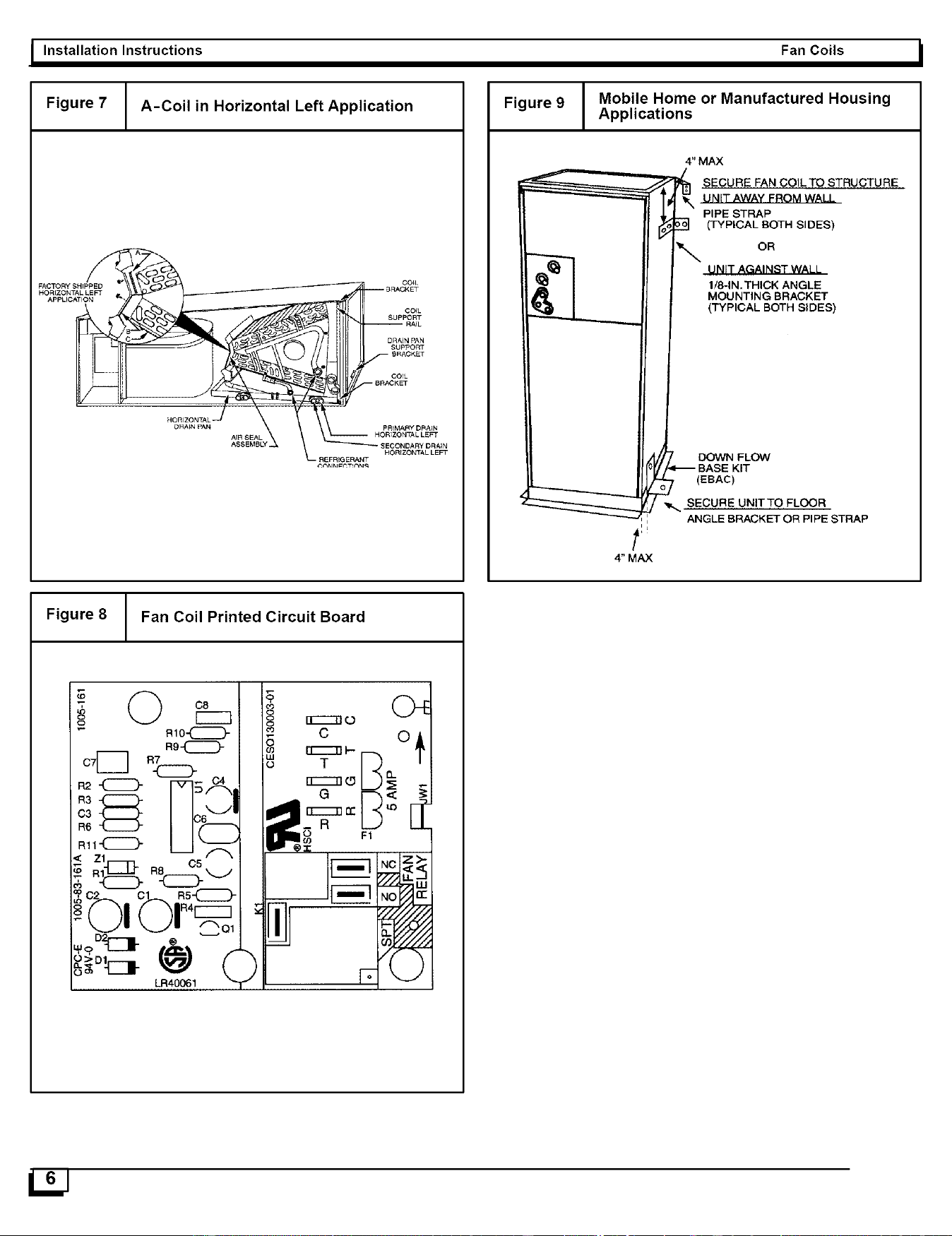
Figure 7 A-Coil in Horizontal Left Application
COIL
HORIZONTAL LEFT
Figure 9 Mobile Home or Manufactured Housing
Applications
4" MAX
4" MAX
SECURE FAN COILTO STRUCTUREUNIT AWAY FROM WALL
PIPE STRAP
(TYPICAL BOTH SIDES)
_. OR
UNIT AGAINST WALL
1/8-IN,THICK ANGLE
MOUNTING BRACKET
(TYPICAL BOTH SIDES)
DOWN FLOW
-- BASE KIT
7 (EBAC)
_. SECURE UNITTO FLOOR
ANGLE BRACKET OR PiPE STRAP
Figure 8 Fan Coil Printed Circuit Board
I Fan Coils
Installation Instructions
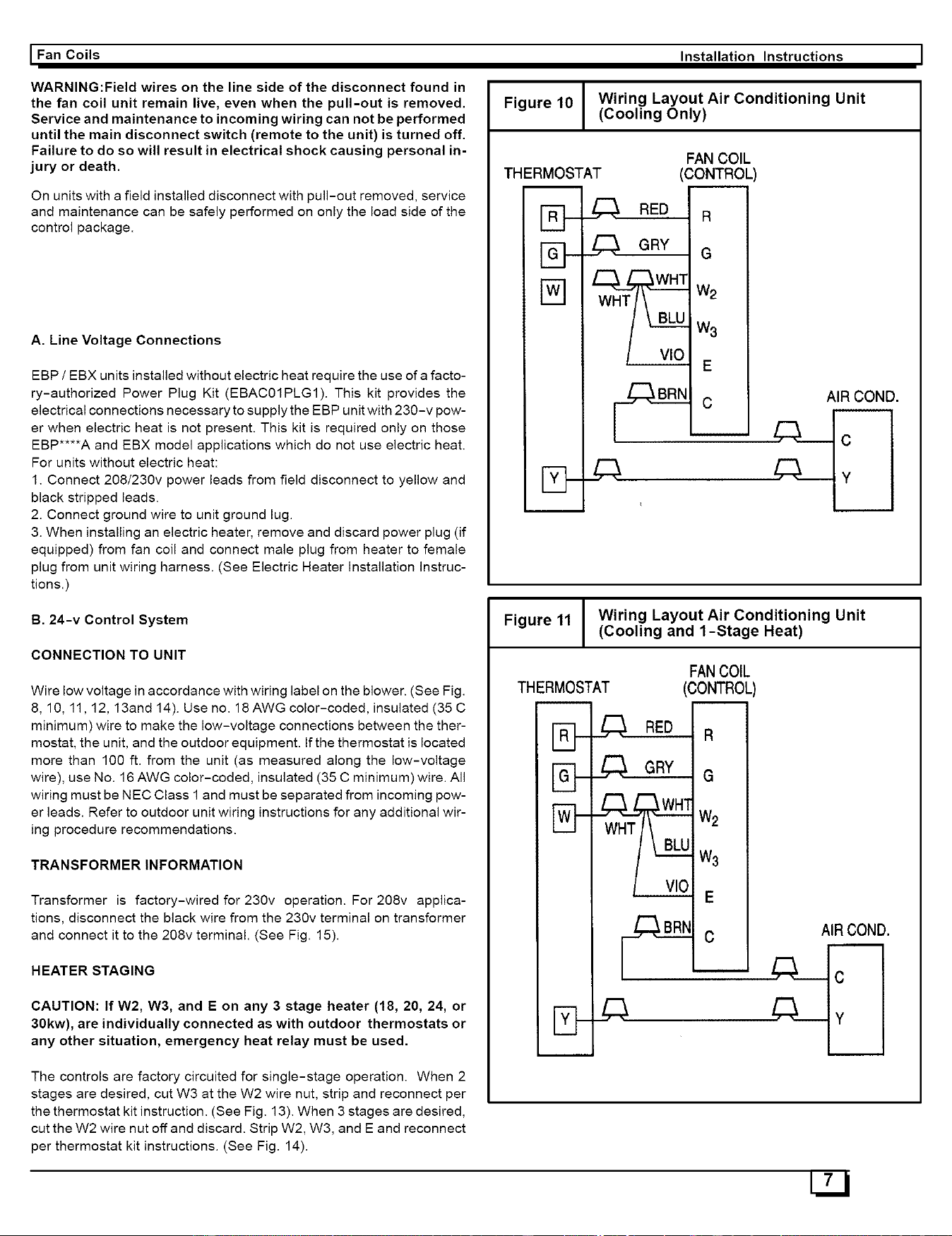
Figure 10 Wiring Layout Air Conditioning Unit
(Cooling Only)
WARNING:Field wires on the line side of the disconnect found in
the fan coil unit remain live, even when the pull-out is removed.
Service and maintenance to incoming wiring can not be performed
until the main disconnect switch (remote to the unit) is turned off.
Failure to do so will result in electrical shock causing personal in-
jury or death.
On units with a field installed disconnect with pull-out removed, service
and maintenance can be safely performed on only the load side of the
control package.
A. Line Voltage Connections
EBP / EBX units installed without electric heat require the use of a facto-
ry-authorized Power Plug Kit (EBACO1PLG1). This kit provides the
electrical connections necessary to supply the EBP unit with 230-v pow-
er when electric heat is not present. This kit is required only on those
EBP****A and EBX model applications which do not use electric heat.
For units without electric heat:
1. Connect 208/230v power leads from field disconnect to yellow and
black stripped leads.
2. Connect ground wire to unit ground lug.
3. When installing an electric heater, remove and discard power plug (if
equipped) from fan coil and connect male plug from heater to female
plug from unit wiring harness. (See Electric Heater Installation instruc-
tions.)
THERMOSTAT
FAN COIL
(CONTROL
_,_ RED R
_,_ GRY G
W3
E
AIR COND.
B. 24-v Control System
CONNECTION TO UNIT
Wire low voltage in accordance with wiring label on the blower. (See Fig.
8, 1O, 11,12, 13and 14). Use no. 18 AWG color-coded, insulated (35 C
minimum) wire to make the low-voltage connections between the ther-
mostat, the unit, and the outdoor equipment. If the thermostat is located
more than 100 ft. from the unit (as measured along the low-voltage
wire), use No. 16 AWG color-coded, insulated (35 C minimum) wire. All
wiring must be NEC Class 1 and must be separated from incoming pow-
er leads. Refer to outdoor unit wiring instructions for any additional wir-
ing procedure recommendations.
TRANSFORMER INFORMATION
Transformer is factory-wired for 230v operation. For 208v applica-
tions, disconnect the black wire from the 230v terminal on transformer
and connect it to the 208v terminal. (See Fig. 15).
HEATER STAGING
CAUTION: If W2, W3, and E on any 3 stage heater (18, 20, 24, or
30kw), are individually connected as with outdoor thermostats or
any other situation, emergency heat relay must be used.
The controls are factory circuited for single-stage operation. When 2
stages are desired, cut W3 at the W2 wire nut, strip and reconnect per
the thermostat kit instruction. (See Fig. 13). When 3 stages are desired,
cut the W2 wire nut off and discard. Strip W2, W3, and E and reconnect
per thermostat kit instructions. (See Fig. 14).
Figure 11 Wiring Layout Air Conditioning Unit
(Cooling and 1-Stage Heat)
THERMOSTAT
I r_ I---
IW_
FANCOIL
(CONTROL
RED R
___ GRY G
Wa
E
AIR COND.
Fan Coils II Installation Instructions
C. Ground Connections
WARNING: According to NEC, ANSI/NFPA 70, and local codes, the
cabinet must have an uninterrupted or unbroken ground to mini-
mize personal injury if an electrical fault should occur. The ground
may consist of electrical wire or metal conduit when installed in ac-
cordance with existing electrical codes. If conduit connection uses
reducing washers, a separate ground wire must be used. Failure
to follow this warning could result in electric shock, fire, or death.
NOTE: Use UL-listed conduit and conduit connector for connecting
supply wire(s) to unit to obtain proper grounding. Grounding may also
be accomplished by using grounding lugs provided in control box.
D. Minimum CFM and Motor Speed Selection
Units with or without electric heaters require a minimum CFM Refer to
the unit wiring label to ensure that the fan speed selected is not lower
than the minimum fan speed indicated.
Fan speed selection is done at the fan relay electronic fan board. To
change motor speeds, disconnect fan lead used on relay terminal (SPT)
and replace with motor speed tap desired. (See Fig. 16). Save insulating
cap and place on motor lead removed from relay.
NOTE: In low static applications, lower motor speed tap should be used
to reduce possibility of water being blown off coil.
All units have 2 or 3 motor speed taps. Low speed (red) is designed for
mismatch outdoor unit applications. Medium speed (blue) is designed
forstraight matched operations. High speed (black) is used with high ex-
ternal static duct systems of straight matched systems.
PROCEDURE 4-REFRIGERANT TUBING
Field-supplied tubing must be of refrigerant grade. Suction tube must
be insulated. Do not use damaged, dirty, or contaminated tubing be-
cause it may plug refrigerant flow-control device. ALWAYS evacuate
the coil and field-supplied tubing to 500 microns before opening outdoor
unit service valves.
CAUTION: Braze with Sil-Fos or Phos-copper on copper to copper
joints and wrap a wet cloth around rear of fitting to prevent damage
to TXV.
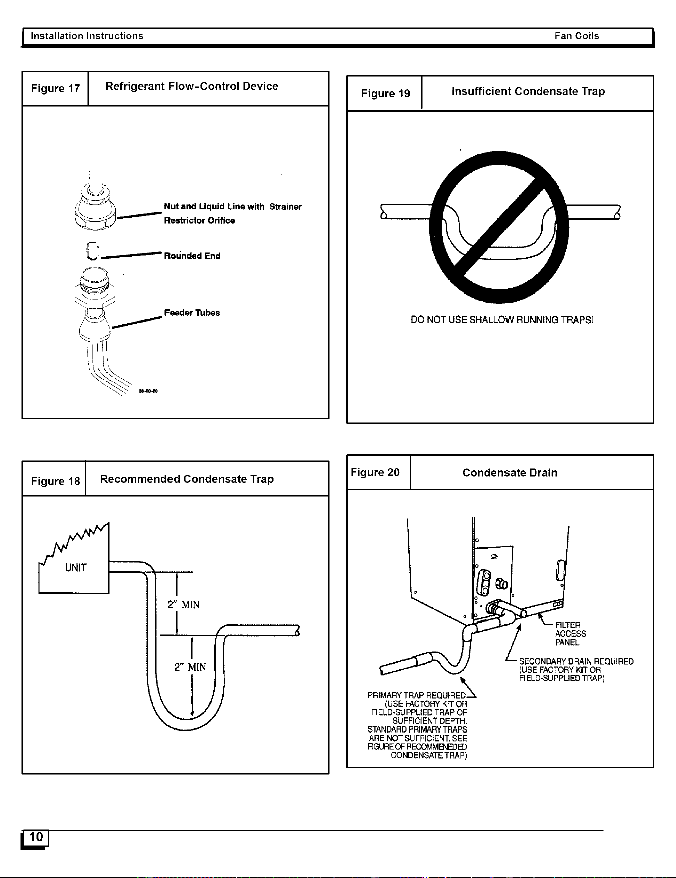
PROCEDURE 5-REFRIGERANT FLOW-CONTROL DEVICE
CAUTION: If using an EBX or an EBP model with field installed TXV
in conjunction with a single-phase reciprocating compressor, a
compressor hard start kit is required.
Check piston size shown on indoor unit rating plate to see if it matches
required piston shown on outdoor unit rating plate. If it does not match,
replace indoor piston with piston shipped with outdoor unit. The piston
shipped with outdoor unit is correct for any approved indoor coil com-
bination. (See Fig. 17). When changing piston, use a back-up wrench.
Hand tighten hex nut, then tighten with wrench 1/2 turn. Do not exceed
30 ft-lbs.
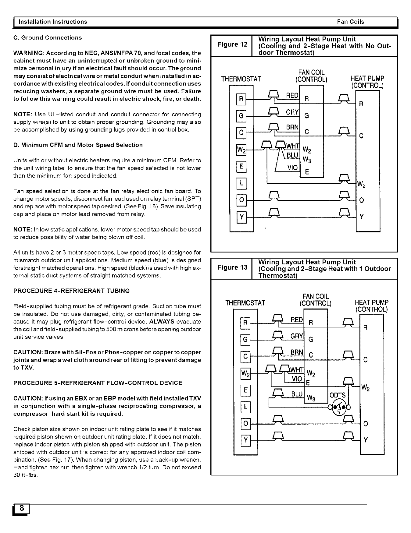
Wiring Layout Heat Pump Unit
Figure 12 (Cooling and 2-Stage Heat with No Out-
door Thermostat)
THERMOSTAT
• n ,
I L1 P,,,,-
IW,_P-
i t] p--
FANCOIL
00NTROL
W3
E ,
HEATPUMP
CONTROL
R
C&-c
w2
Cko
Y
Wiring Layout Heat Pump Unit
Figure 13 (Cooling and 2-Stage Heat with I Outdoor
Thermostat)
THERMOSTAT
i i i I--,-
IVV_t---
I u I,-_
FANCOIL
(CONTROL
G
I
W2
W3_ ODTS
Z;3._
HEATPUMP
(CONTROL
Za.__R
¢
W2
0
Y
I Fan Coils
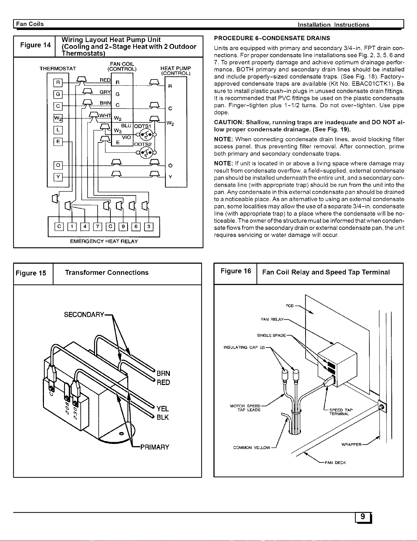
Figure 14
THERMOSTAT
Wiring Layout Heat Pump Unit
(Cooling and 2-Stage Heat with 2 Outdoor
Thermostats)
FAN COIL
(CONTROL)
R
G
c
BLU
W3
VlO
HEAT PUMP
(CONTR._..__OOL)
Z:a._ R
C
w2
0
Ca___¥
EMERGENCY HEAT RELAY
Installation Instructions I
PROCEDURE 6-CONDENSATE DRAINS
Units are equipped with primary and secondary 3/4-in. FPT drain con-
nections. For proper condensate line installations see Fig. 2, 3, 5, 6 and
7. To prevent property damage and achieve optimum drainage perfor-
mance, BOTH primary and secondary drain lines should be installed
and include properly-sized condensate traps. (See Fig. 18). Factory-
approved condensate traps are available (Kit No. EBAC01CTK1). Be
sure to install plastic push-in plugs in unused condensate drain fittings.
it is recommended that PVC fittings be used on the plastic condensate
pan. Finger-tighten plus 1-1/2 turns. Do not over-tighten. Use pipe
dope.
CAUTION: Shallow, running traps are inadequate and DO NOT al-
low proper condensate drainage. (See Fig. 19).
NOTE: When connecting condensate drain lines, avoid blocking filter
access panel, thus preventing filter removal. After connection, prime
both primary and secondary condensate traps.
NOTE: if unit is located in or above a living space where damage may
result from condensate overflow, a field-supplied, external condensate
pan should be installed underneath the entire unit, and a secondary con-
densate line (with appropriate trap) should be run from the unit into the
pan. Any condensate in this external condensate pan should be drained
to a noticeable place. As an alternative to using an external condensate
pan, some localities may allow the use of a separate 3/4-in. condensate
line (with appropriate trap) to a place where the condensate will be no-
ticeable. The owner of the structure must be informed that when conden-
sate flows from the secondary drain or external condensate pan, the unit
requires servicing or water damage will occur.
Figure 15 Transformer Connections
PL-PRIMARY
Figure 16 I Fan Coil Relay and Speed Tap Terminal
FAN
INSULATING CAP
MOTOR SPEED
TAP LEADS
COMMON YELLOW
WRAPPER'
FAN DECK
I Installation Instructions Fan Coils I
Figure 17 Refrigerant Flow-Control Device
"_ Nut and Uquid Line with Strainer
Reatrictor Orifice
0_ -- Rot_nded End
__\_ .._o Feeder Tubes
Figure 19 Insufficient Condensate Trap
DO NOT USE SHALLOW RUNNING TRAPS[
Figure 18 Recommended Condensate Trap
UNIT
2" MIN
Figure 20 Condensate Drain
PRIMARYTRAP REQUIRED_
(USE FACTORYKIT OR
FIELD-SUPPLIEDTRAP OF
SUFFICIENTDEPTH.
STANDARDPRIMARYTRAPS
ARE NOT SUFFICIENT.SEE
RGUREOFRECOMMENEDE)
CONDENSATETRAP)
O
o
LTER
_'_ / ACCESS
PANEL
SECONDARYDRAIN REQUIRED
(USE FACTORYKIT OR
FIELD-SUPPLIEDTRAP)
I Fan Coils Installation Instructions I
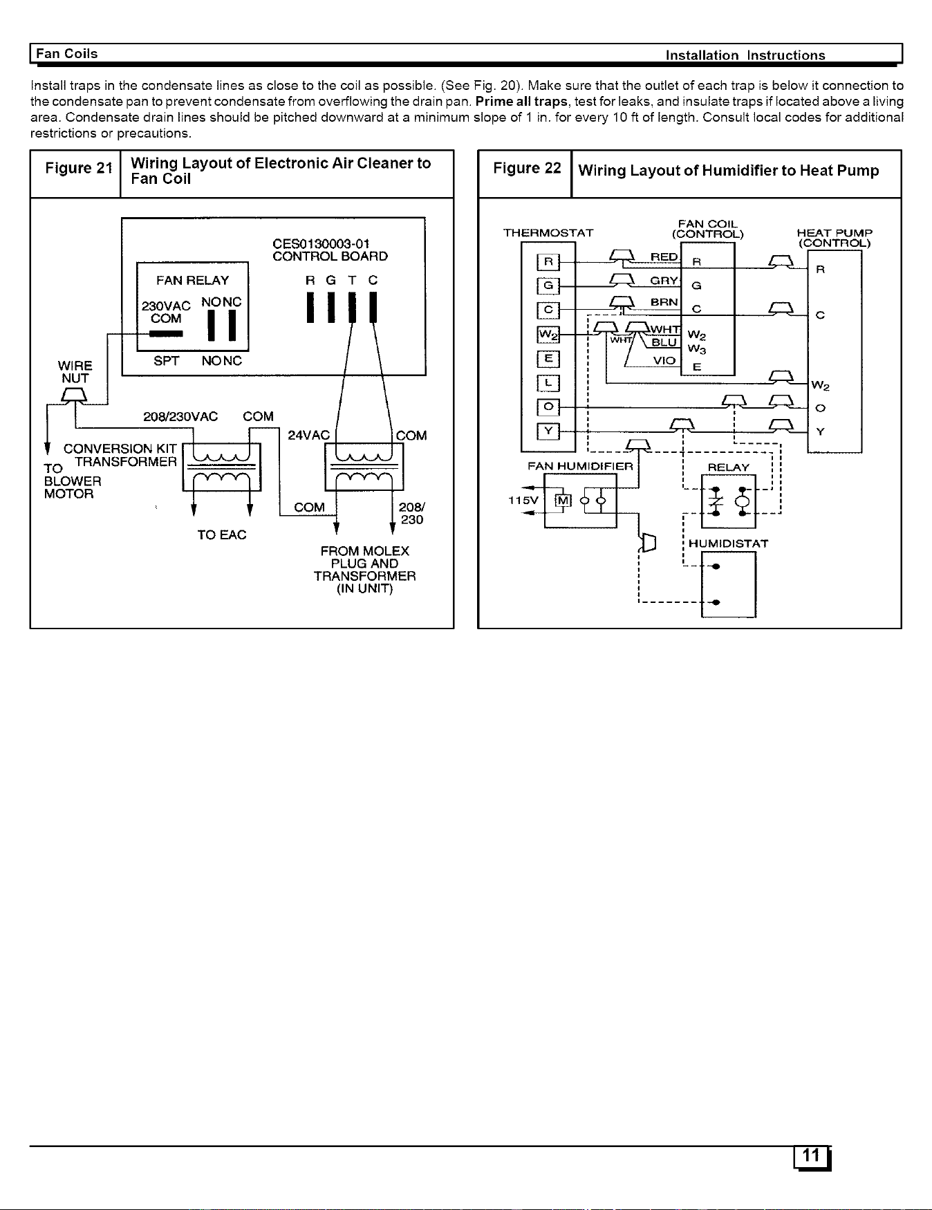
Install traps in the condensate lines as close to the coil as possible. (See Fig. 20). Make sure that the outlet of each trap is below it connection to
the condensate pan to prevent condensate from overflowing the drain pan. Prime all traps, test for leaks, and insulate traps if located above a living
area. Condensate drain lines should be pitched downward at a minimum slope of 1 in. for every 10 ft of length. Consult local codes for additional
restrictions or precautions.
Figure 21 / Wiring Layout of Electronic Air Cleaner to
I
Fan Coil
CES0130003-01
CONTROL BOARD
FAN RELAY R G T C
, 0VACNO O,
It 208/230VA0OOM
, co_vERs,o_,TI... , 2_ '°_
TO TRANSFORMER _'_'_-'J I I
BLOWER C_'_Q I I
MOTOR 1 '_" I 08/
',3O
TO EAC
FROM MOLEX
PLUG AND
TRANSFORMER
(IN UNIT)
Figure 22 Wiring Layout of Humidifier to Heat Pump
FAN COIL
THERMOSTAT (CONTROL)
_R
_a
_c
129-t _ w2
Iw-y_ w_
[_1, --
[NI,, ,
Ell _ i ,___-_ Y
--_ .....-5_---;- _-7---fE--
FAN HUMIDIFIER I _t RELAY _ ,
11 .... ]
(L J HUMIDISTAT
......i_I
HEAT PUMP
CONTROL
E:a__ R
Z::Lc
W2
O
U22J
Fan Coils II Installation Instructions
PROCEDURE 7-ACCESSORIES
A. Electronic Air Cleaner
The Electronic Air Cleaner may be connected to fan coil as shown in Fig.
21. This method requires a field supplied transformer. See Electronic Air
Cleaner literature for kit requirements.
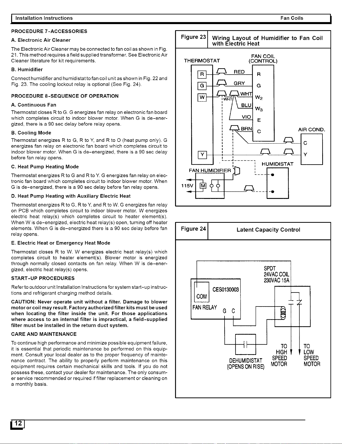
B. Humidifier
Connect humidifier and humidistat to fan coil unit as shown in Fig. 22 and
Fig. 23. The cooling lockout relay is optional (See Fig. 24).
PROCEDURE 8-SEQUENCE OF OPERATION
A. Continuous Fan
Thermostat closes R to G. G energizes fan relay on electronic fan board
which completes circuit to indoor blower motor. When G is de-ener-
gized, there is a 90 sec delay before relay opens.
B. Cooling Mode
Thermostat energizes R to G, R to Y, and R to O (heat pump only). G
energizes fan relay on electronic fan board which completes circuit to
indoor blower motor. When G is de-energized, there is a 90 sec delay
before fan relay opens.
C. Heat Pump Heating Mode
Thermostat energizes R to G and R to Y. G energizes fan relay on elec-
tronic fan board which completes circuit to indoor blower motor. When
G is de-energized, there is a 90 sec delay before fan relay opens.
D. Heat Pump Heating with Auxiliary Electric Heat
Thermostat energizes R to G, R to Y, and R to W. G energizes fan relay
on PCB which completes circuit to indoor blower motor. W energizes
electric heat relay(s) which completes circuit to heater element(s).
When W is de-energized, electric heat relay(s) open, turning off heater
elements. When G is de-energized there is a 90 sec delay before fan
relay opens.
E. Electric Heat or Emergency Heat Mode
Thermostat closes R to W. W energizes electric heat relay(s) which
completes circuit to heater element(s). Blower motor is energized
through normally closed contacts on fan relay. When W is de-ener-
gized, electric heat relay(s) opens.
START-UP PROCEDURES
Refer to outdoor unit Installation Instructions for system start-up instruc-
tions and refrigerant charging method details.
CAUTION: Never operate unit without a filter. Damage to blower
motor or coil may result. Factory authorized filter kits must be used
when locating the filter inside the unit. For those applications
where access to an internal filter is impractical, a field-supplied
filter must be installed in the return duct system.
CARE AND MAINTENANCE
To continue high performance and minimize possible equipment failure,
it is essential that periodic maintenance be performed on this equip-
ment. Consult your local dealer as to the proper frequency of mainte-
nance contract. The ability to properly perform maintenance on this
equipment requires certain mechanical skills and tools. If you do not
possess these, contact your dealer for maintenance. The only consum-
er service recommended or required if filter replacement or cleaning on
a monthly basis.
Figure 23 Wiring Layout of Humidifier to Fan Coil
with Electric Heat
THERMOSTAT
i
[2]-
FAN COIL
(CONTROL
i
RED R
GRY G
W3
E
C AIR COND.
FAN HUMIDIFIER t,_ I r_]
Figure 241
Latent Capacity Control
SPDT
24MACCOILI
c I I
,
---m--I r--l---- TOI TO
HIGH_ LOW
DEHUMIDISTAT SPEED SPEED
(OPENSONRISE) MOTOR MOTOR
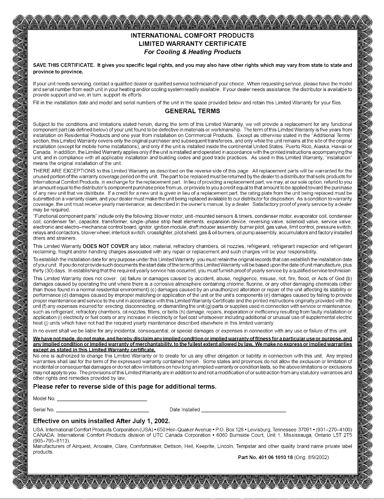
INTERNATIONAL COMFORT PRODUCTS
LIMITED WARRANTY CERTIFICATE
For Cooling & Heating Products
SAVE THIS CERTIFICATE. It gives you specific legal rights, and you may also have other rights which may vary from state to state and
province to province.
If your unit needs servicing, contact a qualified dealer or qualified service technician of your choice. When requesting service, please have the model
and serial number from each unit in your heating and/or cooling system readily available. If your dealer needs assistance, the distributor is available to
provide support and we, in turn, support its efforts.
Fill in the installation date and model and serial numbers of the unit in the space provided below and retain this Limited Warranty for your files.
GENERAL TERMS
Subject to the conditions and limitations stated herein, during the term of this Limited Warranty, we will provide a replacement for any functional
component part (as defined below) of your unit found to be defective in materials or workmanship. The term d this Limited Warranty is five years from
installation on Residential Products and one year from installation on Commercial Products. Except as otherwise stated in the "Additional Terms"
section, this Limited Warranty covers only the original purchaser and subsequent transferees, and only while the unit remains at the site of the original
installation (except for mobile home installations), and only if the unit is installed inside the continental United States, Puerto Rico, Alaska, Hawaii or
Canada. In addition, the Limited Warranty applies only if the unit is installed and operated in accordance with the printed instructions accompanying the
unit, and in compliance with atl applicable installation and building codes and good trade practices. As used in this Limited Warranty, "installation"
means the original installation of the unit.
THERE ARE EXCEPTIONS to this Limited Warranty as described on the reverse side of this page. All replacement parts will be warranted for the
unused portion d the warranty coverage period on the unit. The part to be replaced must be returned by the dealer to a distributor that sells products for
International Comfort Products, in exchange for the replacement part. In lieu of providing a replacement part, we may, at our sole option, refund to you
an amount equal to the distributor's component purchase price from us, or provide to you a credit equal to that amount to be applied toward the purchase
of any new unit that we distribute. Ifa credit for a new unit is given in lieu of a replacement part, the rating plate from the unit being replaced must be
submitted on a warranty claim, and your dealer must make the unit being replaced available to our distributor for dis position. As a condition to warranty
coverage, the unit must receive yearly maintenance, as described in the owner's manual, by a dealer. Satisfactory proof of yearly service by adealer
may be required.
"Functional component parts" include only the following: blower motor, unit-mounted sensors & timers, condenser motor, evaporator coil, condenser
coil, condenser fan, capacitor, transformer, single-phase strip heat elements, expansion device, reversing valve, solenoid valve, service valve,
electronic and electro-mechanicaI control board, ignitor, ignition module, draft inducer assembly, burner pilot, gas valve, limit control, pressure switch,
relays and contactors, btower wheeI, interlock switch, crosslighter, pilot shield, gas & oil burners, oil pump assembly, accumulators and factory installed
driers and strainers.
This Limited Warranty DOES NOT COVER any labor, material, refractory chambers, oiI nozzles, refrigerant, refrigerant inspection and refrigerant
reclaiming, freight and/or handling charges associated with any repair or replacement and such charges wili be your responsibility.
Toestablish the installation date for any purpose under this Limited Warranty, you must retain the original records that can establish the installation date
ofyour unit. Ifyou do not provide such documents the startdate oftheterm ofthis Limited Warranty wilI be based upon the date of unit manufacture, plus
thirty (30)days. In establishing that the required yearly service has occurred, you must furnish proof dyearly service by a qualified service technician.
This Limited Warranty does not cover: (a) failure or damages caused by accident, abuse, negligence, misuse, riot, fire, flood, or Acts of God (b)
damages caused by operating the unit where there is a corrosive atmosphere containing chlorine, fluorine, or any other damaging chemicals (other
than those found in a normal residential environment) (c) damages caused by an unauthorized alteration or repair d the unit affecting its stability or
performance (d) damages caused by improper matching or application of the unit or the unit's components (e) damages caused by failing to provide
proper maintenance and service to the unit in accordance with this Limited Warranty Certificate and the printed instructions originally provided with the
unit (f) any expenses incurred for erecting, disconnecting, or dismantling the unit (g) parts or supplies used in connection with service or maintenance,
such as refrigerant, refractory chambers, oil nozzles, filters, or belts (h) damage, repairs, inoperation or inefficiency resulting from faulty installation or
application (i) electricity or fuel costs or any increase in electricity or fuel cost whatsoever including additional or unusual use of supplemental electric
heat (j) units which have not had the required yearly maintenance described elsewhere in this limited warranty.
In no event shall we be liable for any incidental, consequential, or special damages or expenses in connection with any use or failure of this unit.
We have not made. do not make. and hereby disclaim any implied condition or implied warrantv of fitness for aparticular use or PurPose. and
anv implied condition or implied warrantv of merchantabilitv, to the fullest extent allowed bv law. We make no express or implied warranties
exceDt as stated in this Limited Warrantv certificate,
No one is authorized to change this Limited Warranty or to create for us any other obligation or liability in connection with this unit. Any implied
warranties shall last for the term of the expressed warranty contained herein. Some states and provinces do not allow the exclusion or limitation of
incidental or consequential damages or do not allow limitations on how long an implied warranty or condition lasts, so the above limitations or exclusions
may not apply to you. The provisions d this Limited Warranty are in addition to and not a modification of or subtraction from any statutory warranties and
other rights and remedies provided by law.
Please refer to reverse side of this page for additional terms.
Model No.
Serial No. Date Installed
Effective on units installed After July 1, 2002.
USA: International Comfort Products Corporation (USA) • 650 He!I-Quaker Avenue • P.O. Box 128 ° Lewisburg, Tennessee 37091 • (931-270-4100)
CANADA: international Comfort Products division of UTC Canada Corporation • 6060 Burnside Court, Unit 1, Mississauga, Ontario L5T 2T5
(905-795-8113).
Manufacturers of Airquest, Arcoaire, Clare, Comfortmaker, Dettson, He!l, Keeprite, Lincoln, Tempstar and other quality brand name private label
products.
Part No. 401 06 1010 18 (Orig. 8/9/2002)
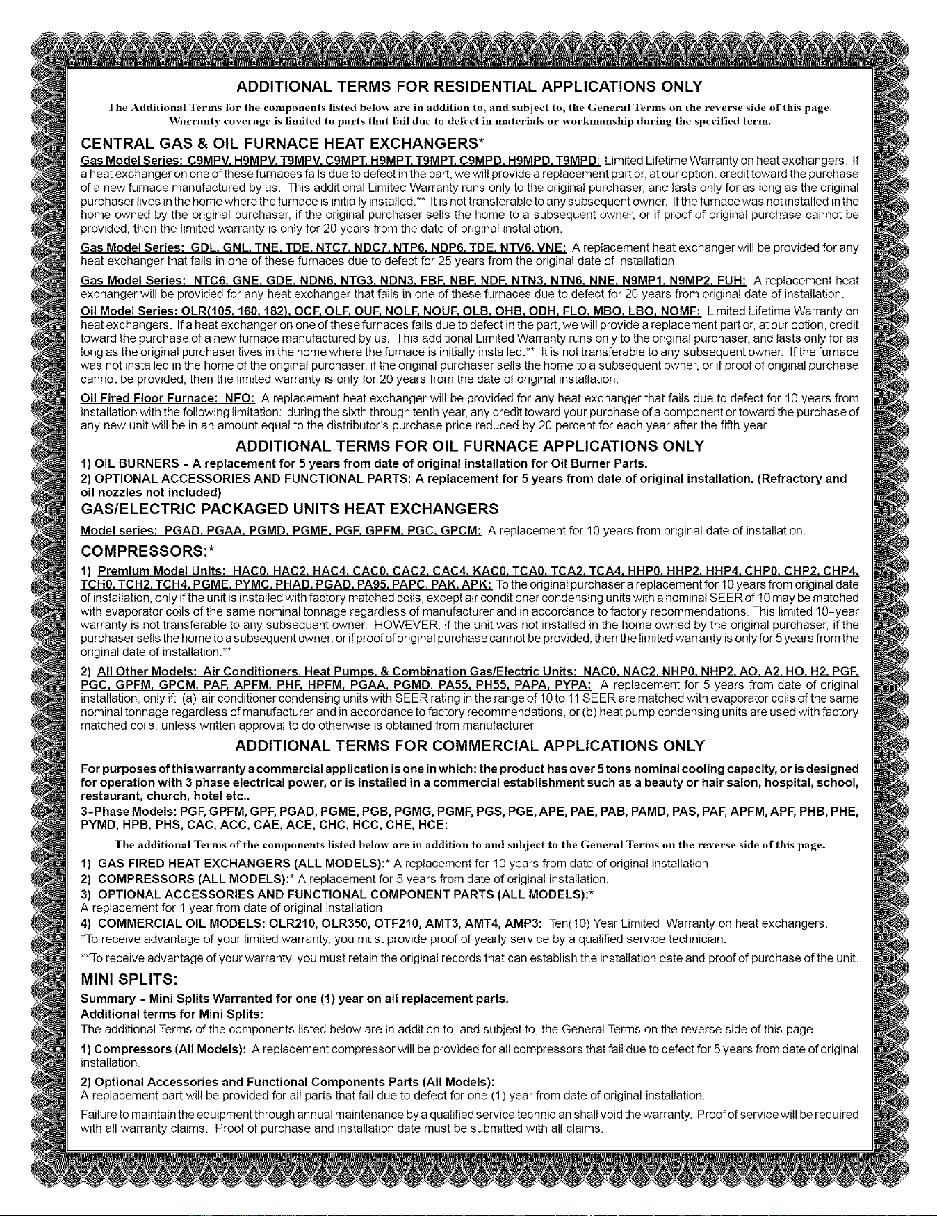
ADDITIONAL TERMS FOR RESIDENTIAL APPLICATIONS ONLY
The Additional Terms for the components listed below are in addition to, and subject to, the General Terms on the reverse side of this page.
VVarranty coverage is limited to parts that fail due to defect in materials or workmanship during the specified term.
CENTRAL GAS & OIL FURNACE HEAT EXCHANGERS*
Gas Model Series: C9MPV. H9MPV. T9MPV. CgMPT. H9MPT. T9MPT. C9MPD. H9MPD. T9MPD: Limited Lifetime Warranty on heat exchangers. If
a heat exchanger on one of these furnaces fails due to defect in the part, we wilt provide a replacement part or, at our option, credit toward the purchase
of a new furnace manufactured by us. This additional Limited Warranty runs only to the original purchaser, and lasts only for as long as the original
purchaserlivesinthehomewherethefurnaceis initially installed.** Itisnottransferabletoanysubsequentowner. Ifthefurnacewas notinstalledinthe
home owned by the original purchaser, if the original purchaser sells the home to a subsequent owner, or if proof of original purchase cannot be
provided, then the limited warranty is only for 20 years from the date of original installation.
Gas Model Series: GDL. GNL. TNE. TDE. NTC7. NDC7. NTP6. NDP6. TDE. NTV6. VNE: A replacement heat exchanger will be provided for any
heat exchanger that fails in one of these furnaces due to defect for 25 years from the original date of installation.
Gas Model Series: NTC6. GNE. GDE. NDN6. NTG3. NDN3. FBF. NBF. NDF. NTN3. NTN6. NNE. N9MP1. N9MP2. FUH: A replacement heat
exchanger will be provided for any heat exchanger that fails in one of these furnaces due to defect for 20 years from original date of installation.
Oil Model Series: OLR(105, 160, 182), OCF, OLF, our, NOLF, NOUF, OLB, OHB, ODH, FLO, MBO, LBO, NOMF: Limited Lifetime Warranty on
heat exchangers. If a heat exchanger on one of these furnaces fails due to defect in the part, we will provide a replacement part or, at our option, credit
toward the purchase of a new furnace manufactured by us. This additional Limited Warranty runs only to the original purchaser, and lasts only for as
long as the original purchaser lives in the home where the furnace is initially installed.** It is not transferable to any subsequent owner. If the furnace
was not installed in the home of the original purchaser, if the original purchaser sells the home to a subsequent owner, or if proof of original purchase
cannot be provided, then the limited warranty is only for 20 years from the date of original installation.
Oil Fired Floor Furnace: NFO: A replacement heat exchanger will be provided for any heat exchanger that fails due to defect for 10 years from
installation with the following limitation: during the sixth through tenth year, any credit toward your purchase of a component or toward the purchase of
any new unit will be in an amount equal to the distributor's purchase price reduced by 20 percent for each year after the fifth year.
ADDITIONAL TERMS FOR OIL FURNACE APPLICATIONS ONLY
1) OIL BURNERS - A replacement for 5 years from date of original installation for Oil Burner Parts.
2) OPTIONAL ACCESSORIES AND FUNCTIONAL PARTS: A replacement for 5 years from date of original installation. (Refractory and
oil nozzles not included)
GAS/ELECTRIC PACKAGED UNITS HEAT EXCHANGERS
Model series: PGAD. PGAA. PGMD. PGME. PGF. GPFM. PGC. GPCM: A replacement for 10 years from original date of installation.
COMPRESSORS:*
1) Premium Model Units: HAC0. HAC2. HAC4. CAC0. CAC2. CAC4. KAC0. TCA0. TCA2. TCA4. HHP0. HHP2. HHP4. CliP0. CliP2. CliP4.
TCH0. TCH2. TCH4. PGME. PYMC. PHAD. PGAD. PA95. PAPC. PAK. APK: Tothe original purchaser a replacement for 10 years from original date
of installation, only if the unit is installed with factory matched coils, except air conditioner condensing units with a nominal SEER of !0 may be matched
with evaporator coils of the same nominal tonnage regardless of manufacturer and in accordance to factory recommendations. This limited 10-year
warranty is not transferable to any subsequent owner. HOWEVER, if the unit was not installed in the home owned by the original purchaser, if the
purchaser sells the home to a subsequent owner, or if proof of original purchase cannot be provided, then the limited warranty is only for 5years from the
original date of installation.**
2) All Other Models: Air Conditioners. Heat PumPs. & Combination Gas/Electric Units: NAC0. NAC2. NHP0. NHP2. An. A2. HO. H2. PGF.
PGC, GPFM, GPCM, PAl=, APFM, PHI:, HPFM, PGAA, PGMD, PA55, PH55, PAPA, PYPA: A replacement for 5 years from date of original
installation, only if: (a) air conditioner condensing units with SEER rating in the range of 10 to 11 SEER are matched with evaporator coils of the same
nominal tonnage regardless of manufacturer and in accordance to factory recommendations, or (b) heat pump condensing units are used with factory
matched coils, unless written approval to do otherwise is obtained from manufacturer.
ADDITIONAL TERMS FOR COMMERCIAL APPLICATIONS ONLY
For purposes of this warranty a commercial application is one in wh ich: the product has over 5tons nominal cooling capacity, or is designed
for operation with 3 phase electrical power, or is installed in a commercial establishment such as a beauty or hair salon, hospital, school,
restaurant, church, hotel etc..
3-Phase Models: PGF, GPFM, GPF, PGAD, PGME, PGB, PGMG, PGMF, PGS, PGE, APE, PAE, PAB, PAMD, PAS, PAr, APFM, APF, PHB, PHE,
PYMD, HPB, PHS, CAC, ACC, CAE, ACE, CHC, HCC, CHE, HCE:
The additional Terms of the components listed below are ill addition to and subject to the General Terms on the reverse side of this page.
1) GAS FIRED HEAT EXCHANGERS (ALL MODELS):* A replacement for 10 years from date of original installation.
2) COMPRESSORS (ALL MODELS):* A replacement for 5 years from date of original installation.
3) OPTIONAL ACCESSORIES AND FUNCTIONAL COMPONENT PARTS (ALL MODELS):*
A replacement for 1 year from date of original installation.
4) COMMERCIAL OIL MODELS: OLR210, OLR350, OTF210, AMT3, AMT4, AMP3: Ten(!0) Year Limited Warranty on heat exchangers.
*To receive advantage of your limited warranty, you must provide proof of yearly service by a qualified service technician.
**To receive advantage of your warranty, you must retain the original records that can establish the installation date and proof of purchase of the unit.
MINI SPLITS:
Summary - Mini Splits Warranted for one (1) year on all replacement parts.
Additional terms for Mini Splits:
The additional Terms of the components listed below are in addition to, and subject to, the General Terms on the reverse side of this page.
1) Compressors (All Models): A replacement compressor will be provided for all compressors that fail due to defect for 5years from date of original
installation.
2) Optional Accessories and Functional Components Parts (All Models):
A replacement part will be provided for all parts that fail due to defect for one (1) year from date of original installation.
Failure to maintain the equipment through annual maintenance by a qualified service technician shall void the warranty. Proof of servicewilI be required
with atl warranty claims. Proof of purchase and installation date must be submitted with all claims.