
M100
Self-Propelled Windrowe
r
OPERATOR’S MANUAL
Part #169304 Revision
C
$25
This Manual contains instructions for “SAFETY”, “OPERATION”, and “MAINTENANCE/SERVICE” for your new MacDon
Model M100 Self-Propelled Windrower.
CALIFORNIA
Proposition 65 Warning
Diesel engine exhaust and some of its constituents are known
to the State of California to cause cancer, birth defects, and
other reproductive harm.
169304 1 Rev. C
1 INTRODUCTION
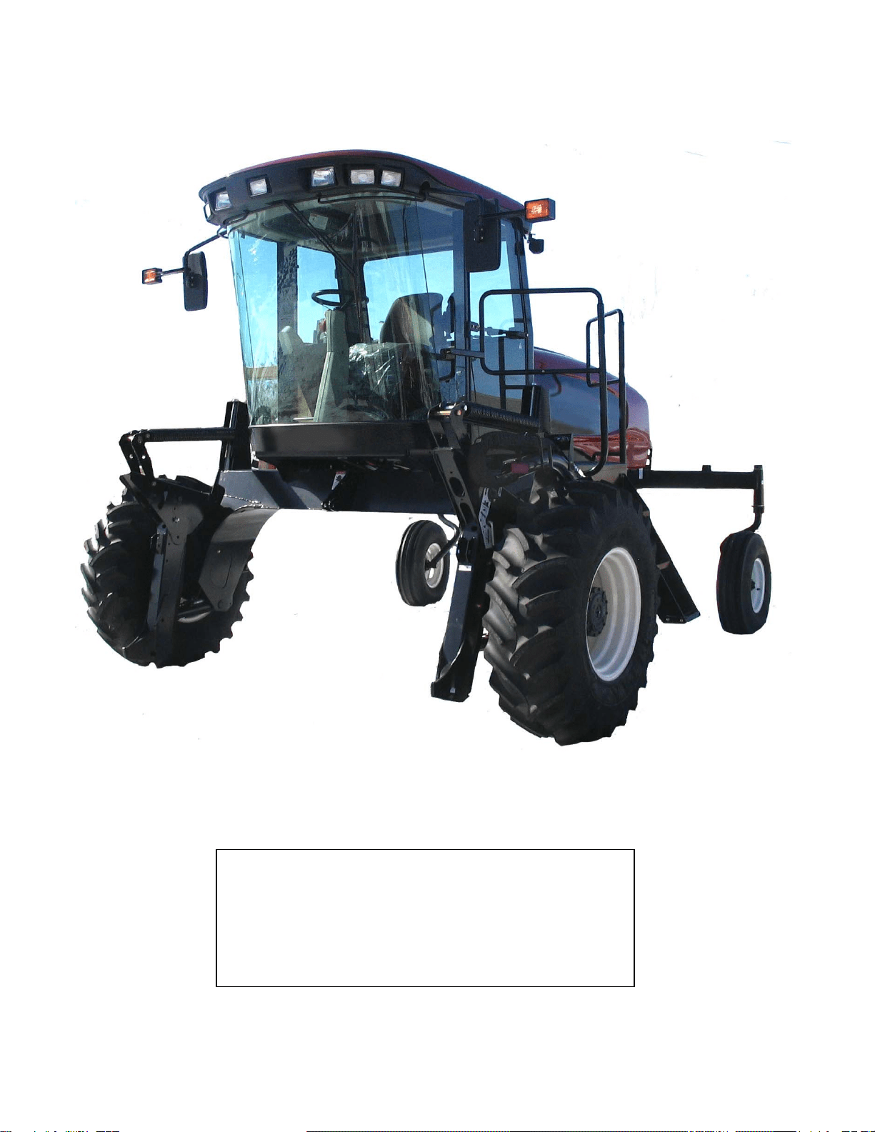
This manual contains information on the MacDon Model M100 Self-Propelled Windrower that is designed to cut
and lay in windrows, a wide variety of grain, hay and specialty crops. Windrowing allows starting the harvest
earlier, protects the crop from wind damage, and gives you more flexibility in scheduling combine time.
The power unit (referred to in this manual as the “windrower”), when coupled with one of the specially designed
auger, or draper headers, provides a package which incorporates many features and improvements in design.
This manual must be used in conjunction with your Header Operator's Manual.
CAREFULLY READ ALL THE MATERIAL PROVIDED BEFORE ATTEMPTING TO UNLOAD, ASSEMBLE, OR
USE THE MACHINE.
Use this manual as your first source of information about the machine. If you follow the instructions given in this
manual, your M100 Windrower will work well for many years. If you require more detailed service information,
check with your dealer.
Use the Table of Contents and the Index to guide you to specific areas. Study the Table of Contents to familiarize
yourself with how the material is organized.
Keep this manual handy for frequent reference and to pass on to new operators or owners. Call your dealer if you
need assistance, information, or additional copies of this manual. A manual storage case is provided in the cab.
NOTE: Right-Hand and Left-Hand designations are determined by the operator’s position, facing the direction of
travel.
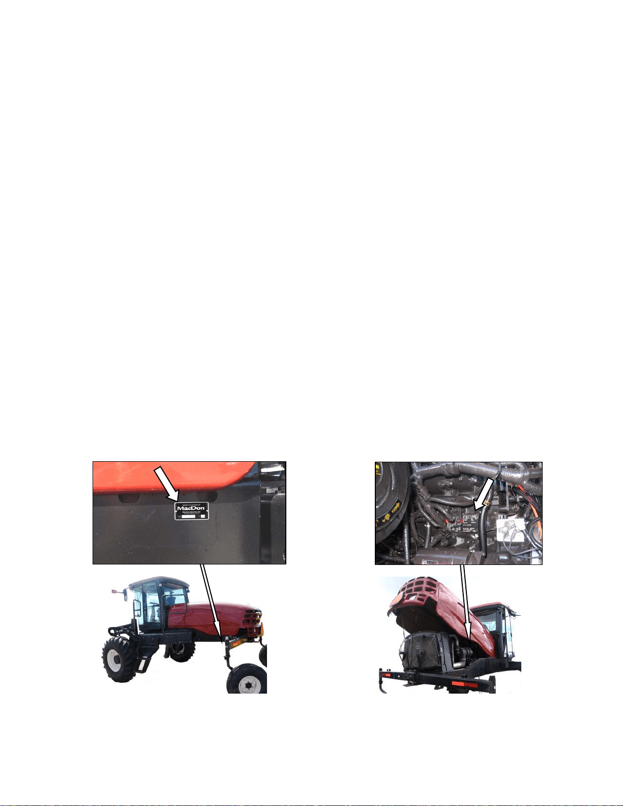
RECORD THE SERIAL NUMBERS IN THE SPACES BELOW.
Windrower_______________________
Serial Number plate is located on the left side of
the main frame, near the rear corner.
M100 Diesel Engine___________________________
Serial Number plate is located on the right side of the
engine block.

TABLE OF CONTENTS
169304 2 Rev. C
Section/Title Page
1 INTRODUCTION ............................................................................................................................................ 1
2 SAFETY ......................................................................................................................................................... 5
2.1 SAFETY ALERT SYMBOL .................................................................................................................... 5
2.2 SIGNAL WORDS ................................................................................................................................... 5
2.3 SAFETY SIGNS ..................................................................................................................................... 5
2.3.1 Safety Sign Installation ...................................................................................................................................... 5
2.3.2 Safety Sign Locations ....................................................................................................................................... 5
2.4 GENERAL SAFETY ............................................................................................................................. 10
3 ACRONYMS AND ABBREVIATIONS ......................................................................................................... 12
4 SPECIFICATIONS ....................................................................................................................................... 13
4.1 WINDROWER DIMENSIONS .............................................................................................................. 13
4.2 SPECIFICATIONS ............................................................................................................................... 14
5 OPERATOR’S STATION ............................................................................................................................. 16
5.1 OPERATOR CONSOLE ...................................................................................................................... 16
5.2 SEAT ADJUSTMENTS ........................................................................................................................ 16
5.3 TRAINING SEAT (Optional) ................................................................................................................ 17
5.4 SEAT BELTS ....................................................................................................................................... 17
5.5 STEERING COLUMN ADJUSTMENT ................................................................................................ 17
5.6 OPERATOR PRESENCE .................................................................................................................... 18
5.6.1 Header Drive ................................................................................................................................................... 18
5.6.2 Transmission ................................................................................................................................................... 18
5.6.3 Engine ............................................................................................................................................................. 18
5.7 LIGHTS ................................................................................................................................................ 19
5.7.1 Field Lighting ................................................................................................................................................... 19
5.7.2 Road Lighting .................................................................................................................................................. 20
5.7.3 Beacon Lighting – Export ................................................................................................................................ 20
5.8 WINDSHIELD WIPERS ....................................................................................................................... 21
5.9 REAR VIEW MIRRORS ....................................................................................................................... 21
5.10 CAB TEMPERATURE ......................................................................................................................... 22
5.10.1 Controls ........................................................................................................................................................... 22
5.10.2 Air Distribution ................................................................................................................................................. 22
5.10.3 Heater Shut-Off Valve ..................................................................................................................................... 22
5.10.4 A/C Compressor Protection ............................................................................................................................. 23
5.11 INTERIOR LIGHTS .............................................................................................................................. 23
5.12 OPERATOR AMENITIES .................................................................................................................... 23
5.13 RADIOS ............................................................................................................................................... 24
5.13.1 AM/FM Radio .................................................................................................................................................. 24
5.13.2 Antenna Mounting ........................................................................................................................................... 24
5.14 HORN .................................................................................................................................................. 24
5.15 ENGINE CONTROLS/GAUGES .......................................................................................................... 25
5.16 WINDROWER CONTROLS ................................................................................................................ 26
5.17 HEADER CONTROLS ......................................................................................................................... 27
5.17.1 Header Engage Switch ................................................................................................................................... 27
5.17.2 GSL Header Switches ..................................................................................................................................... 27
5.17.3 Console Header Switches ............................................................................................................................... 29
5.18 CAB DISPLAY MODULE (CDM) ......................................................................................................... 30
5.18.1 Engine and Windrower Functions ................................................................................................................... 30
5.18.2 Header Functions ............................................................................................................................................ 30
5.18.3 Operating Screens .......................................................................................................................................... 31
5.18.4 Cab Display Module (CDM) Warnings/Alarms ................................................................................................ 36
5.18.5 Cab Display Module (CDM) Programming ...................................................................................................... 39
5.18.6 Engine Error Codes ......................................................................................................................................... 44
5.18.7 CDM & WCM Fault Codes .............................................................................................................................. 44
6 OPERATION ................................................................................................................................................ 45
6.1 OWNER/OPERATOR RESPONSIBILITIES ........................................................................................ 45
6.2 SYMBOL DEFINITIONS ...................................................................................................................... 45
6.2.1 Engine Functions ............................................................................................................................................ 45
6.2.2 Windrower Operating Symbols ........................................................................................................................ 45

TABLE OF CONTENTS
169304 3 Rev. C
6.2.3 Header Functions ............................................................................................................................................. 46
6.3 WINDROWER OPERATION ............................................................................................................... 47
6.3.1 Operational Safety ........................................................................................................................................... 47
6.3.2 Break-In Period ................................................................................................................................................ 47
6.3.3 Pre-Season Check ........................................................................................................................................... 48
6.3.4 Daily Check ...................................................................................................................................................... 48
6.3.5 Engine Operation ............................................................................................................................................. 49
6.3.6 Driving the Windrower ...................................................................................................................................... 53
6.3.7 Adjustable Caster Tread Width (Optional) ....................................................................................................... 57
6.3.8 Transporting ..................................................................................................................................................... 58
6.3.9 Storage ............................................................................................................................................................ 68
6.4 HEADER OPERATION ........................................................................................................................ 69
6.4.1 Header Lift Cylinder Stops ............................................................................................................................... 69
6.4.2 Header Flotation .............................................................................................................................................. 70
6.4.3 Header Drive .................................................................................................................................................... 73
6.4.4 Header Angle ................................................................................................................................................... 74
6.4.5 Cutting Height .................................................................................................................................................. 75
6.5 D SERIES HEADER OPERATION ...................................................................................................... 77
6.5.1 Header Attachments ........................................................................................................................................ 77
6.5.2 Header Detachment ......................................................................................................................................... 80
6.5.3 Header Position Adjustments ........................................................................................................................... 82
6.5.4 Reel Fore-Aft Position (Optional) ..................................................................................................................... 82
6.5.5 Reel Height ...................................................................................................................................................... 82
6.5.6 Reel Speed ...................................................................................................................................................... 83
6.5.7 Draper Speed .................................................................................................................................................. 85
6.5.8 Knife Speed ..................................................................................................................................................... 87
6.5.9 Deck Shift (Optional) ........................................................................................................................................ 88
6.6 A SERIES HEADER OPERATION ...................................................................................................... 89
6.6.1 Header Attachment – A Series ........................................................................................................................ 89
6.6.2 Header Detachment ......................................................................................................................................... 92
6.6.3 Auger Speed .................................................................................................................................................... 94
6.6.4 Reel Speed ...................................................................................................................................................... 95
6.6.5 Knife Speed ..................................................................................................................................................... 96
7 MAINTENANCE/SERVICE .......................................................................................................................... 98
7.1 PREPARATION FOR SERVICING ..................................................................................................... 98
7.1.1 Welding Precautions ........................................................................................................................................ 98
7.2 RECOMMENDED SAFETY PROCEDURES ...................................................................................... 98
7.3 MAINTENANCE SPECIFICATIONS ................................................................................................... 99
7.3.1 Recommended Fluids, Fuel, and Lubricants .................................................................................................... 99
7.3.2 Recommended Torques ................................................................................................................................ 100
7.3.3 Conversion Chart ........................................................................................................................................... 102
7.4 ENGINE COMPARTMENT HOOD .................................................................................................... 103
7.5 MAINTENANCE PLATFORM ............................................................................................................ 104
7.5.1 Opening/Closing Platform .............................................................................................................................. 104
7.5.2 Opening/Closing Platform for Major Servicing ............................................................................................... 104
7.6 LUBRICATING THE WINDROWER .................................................................................................. 105
7.6.1 Procedure ...................................................................................................................................................... 105
7.6.2 Lubrication Points .......................................................................................................................................... 106
7.7 OPERATOR’S STATION ................................................................................................................... 107
7.7.1 Seat Belts ...................................................................................................................................................... 107
7.7.2 Safety Systems .............................................................................................................................................. 107
7.7.3 Traction Drive Adjustments ............................................................................................................................ 108
7.7.4 Neutral Set-Up Procedure .............................................................................................................................. 113
7.7.5 HVAC System ................................................................................................................................................ 115
7.8 ENGINE ............................................................................................................................................. 118
7.8.1 General Engine Inspection ............................................................................................................................. 118
7.8.2 Oil Level ......................................................................................................................................................... 118
7.8.3 Changing Oil and Oil Filter ............................................................................................................................. 119
7.8.4 Air Intake System ........................................................................................................................................... 120
7.8.5 Fuel System ................................................................................................................................................... 123
7.8.6 Engine Cooling System .................................................................................................................................. 128
7.8.7 Exhaust System ............................................................................................................................................. 131
7.8.8 Belts ............................................................................................................................................................... 132

TABLE OF CONTENTS
169304 4 Rev. C
7.8.9 Engine Speed ................................................................................................................................................ 133
7.9 COOLING BOX .................................................................................................................................. 134
7.9.1 Cooling Box Screen Cleaners ....................................................................................................................... 134
7.9.2 Cooling Box Maintenance ............................................................................................................................. 136
7.10 ELECTRICAL SYSTEM ..................................................................................................................... 138
7.10.1 Battery ........................................................................................................................................................... 138
7.10.2 Headlights ..................................................................................................................................................... 143
7.10.3 Flood Lights - Forward .................................................................................................................................. 144
7.10.4 Flood Lights - Rear ........................................................................................................................................ 145
7.10.5 Swath Lights .................................................................................................................................................. 146
7.10.6 Ambient Light ................................................................................................................................................ 148
7.10.7 Turn Signal Indicators ................................................................................................................................... 148
7.10.8 Circuit Breakers and Fuses ........................................................................................................................... 149
7.11 HYDRAULIC SYSTEM ...................................................................................................................... 152
7.11.1 Oil Level ........................................................................................................................................................ 152
7.11.2 Changing Hydraulic Oil ................................................................................................................................. 154
7.11.3 Hydraulic Oil Cooler ...................................................................................................................................... 154
7.11.4 Hydraulic Oil Filters ....................................................................................................................................... 154
7.11.5 Header and Reel Hydraulics ......................................................................................................................... 155
7.11.6 Traction Drive Hydraulics .............................................................................................................................. 158
7.11.7 Hoses and Lines ........................................................................................................................................... 159
7.12 WHEELS AND TIRES ....................................................................................................................... 160
7.12.1 Drive Wheels ................................................................................................................................................. 160
7.12.2 Caster Wheels ............................................................................................................................................... 163
7.13 MAINTENANCE SCHEDULE ............................................................................................................ 167
7.13.1 Break-In Inspection ....................................................................................................................................... 167
7.13.2 Interval Maintenance ..................................................................................................................................... 168
8 TROUBLESHOOTING ............................................................................................................................... 171
8.1 ENGINE ............................................................................................................................................. 171
8.2 ELECTRICAL ..................................................................................................................................... 173
8.3 HYDRAULICS .................................................................................................................................... 174
8.4 HEADER DRIVE ................................................................................................................................ 174
8.5 TRACTION DRIVE ............................................................................................................................ 175
8.6 STEERING AND GROUND SPEED CONTROL ............................................................................... 176
8.7 CAB AIR ............................................................................................................................................. 177
8.8 OPERATOR’S STATION ................................................................................................................... 179
9 OPTIONS ................................................................................................................................................... 180
9.1 REEL DRIVE & LIFT PLUMBING ...................................................................................................... 180
9.2 WINDROWER HYDRAULIC COMPLETION FOR DRAPER HEADER REEL FORE/AFT .............. 180
9.3 BOOSTER SPRING KIT .................................................................................................................... 180
9.4 INTERNAL BOOSTER SPRING KIT ................................................................................................. 180
9.5 LIGHT HEADER FLOTATION KIT .................................................................................................... 180
9.6 AM-FM RADIO ................................................................................................................................... 180
9.7 HYDRAULIC CENTER LINK ............................................................................................................. 180
9.8 FAN AIR BAFFLE KIT ....................................................................................................................... 180
9.9 TRAINING SEAT ............................................................................................................................... 180
9.10 KNIFE SPEED, REEL SPEED INDEX, AND TILT SENSOR MODULE ........................................... 180
9.11 ANTI-SHIMMY KIT FOR CASTERS .................................................................................................. 180
9.12 SWATH ROLLER .............................................................................................................................. 180
9.13 WARNING BEACONS ....................................................................................................................... 180
9.14 AUTO-STEER .................................................................................................................................... 180
9.15 ENGINE BLOCK HEATER ................................................................................................................ 180
9.16 TRANSPORT DRAWBAR ................................................................................................................. 181
INDEX ................................................................................................................................................................. 181
CDM/WCM FAULT CODES ................................................................................................................................ 184
ENGINE ERROR CODES ................................................................................................................................... 185
HYDRAULIC AND ELECTRICAL SCHEMATICS
SAFETY
169304 5 Rev. C
2 SAFETY
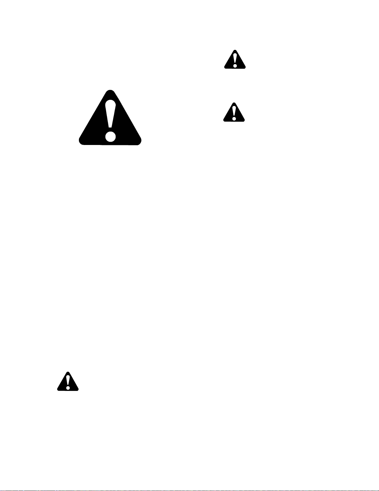
2.1 SAFETY ALERT SYMBOL
This safety alert symbol indicates important
safety messages in this manual and on safety
signs on the machine.
This symbol means:
ATTENTION!
BECOME ALERT!
YOUR SAFETY IS INVOLVED!
Carefully read and follow the safety message
accompanying this symbol.
WHY IS SAFETY IMPORTANT TO YOU?
ACCIDENTS DISABLE AND KILL
ACCIDENTS COST
ACCIDENTS CAN BE AVOIDED
2.2 SIGNAL WORDS
Note the use of the signal words DANGER,
WARNING, and CAUTION with safety
messages. The appropriate signal word for each
message has been selected using the following
guidelines:
DANGER
Indicates an imminently hazardous situation
that, if not avoided, will result in death or
serious injury.
WARNING
Indicates a potentially hazardous situation
that, if not avoided, could result in death or
serious injury. It is also used to alert against
unsafe practices.
CAUTION
Indicates a potentially hazardous situation
that, if not avoided, may result in minor or
moderate injury. It is also used as a reminder
of good safety practices.
2.3 SAFETY SIGNS
2.3.1 Safety Sign Installation
Refer to the illustration on this and following
pages and proceed as follows:
a. Be sure the installation area is clean and dry.
b. Decide on the exact location before you remove
the decal backing paper.
c. Remove the smaller portion of the split backing
paper.
d. Place the sign in position and slowly peel back
the remaining paper, smoothing the sign as it is
applied.
e. Small air pockets can be smoothed out or
pricked with a pin.
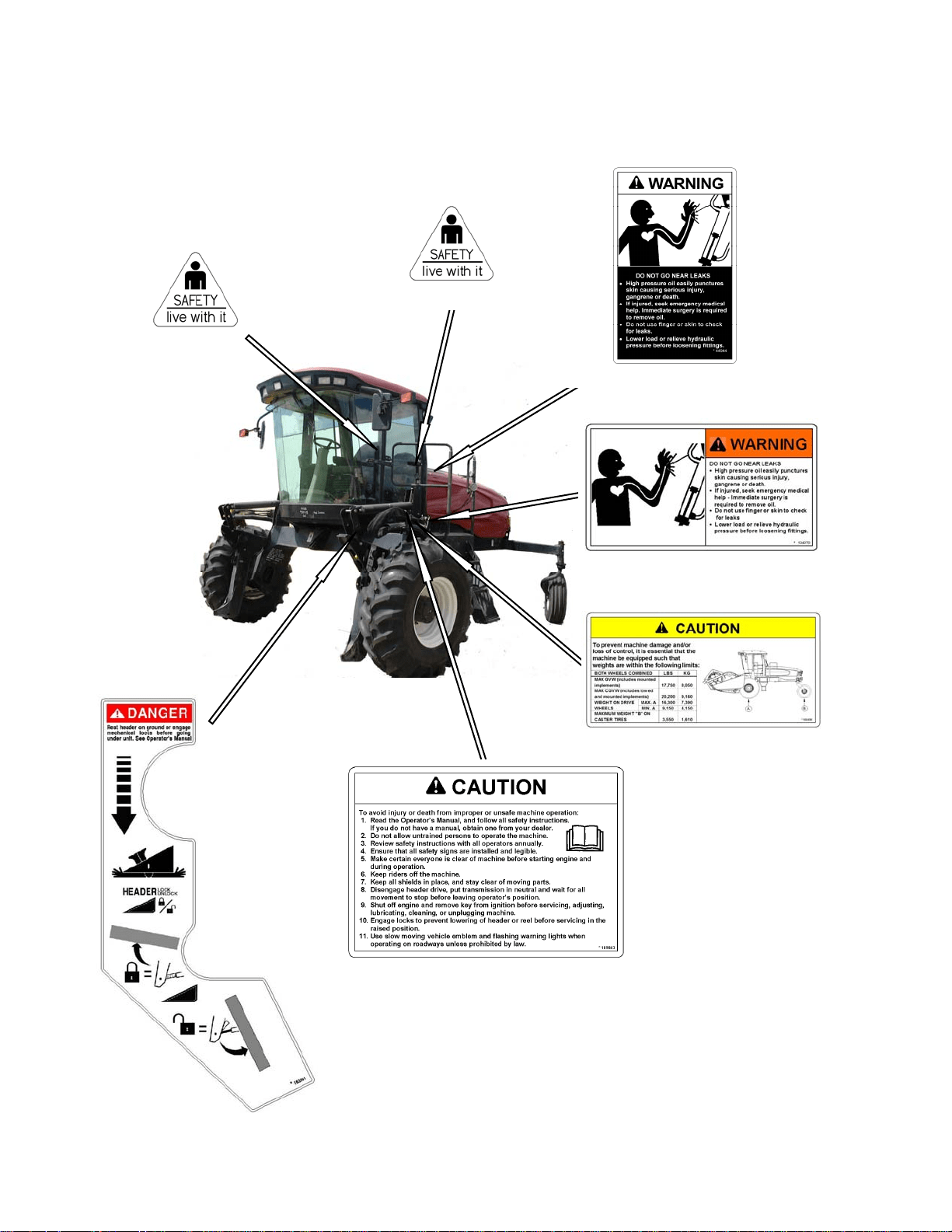
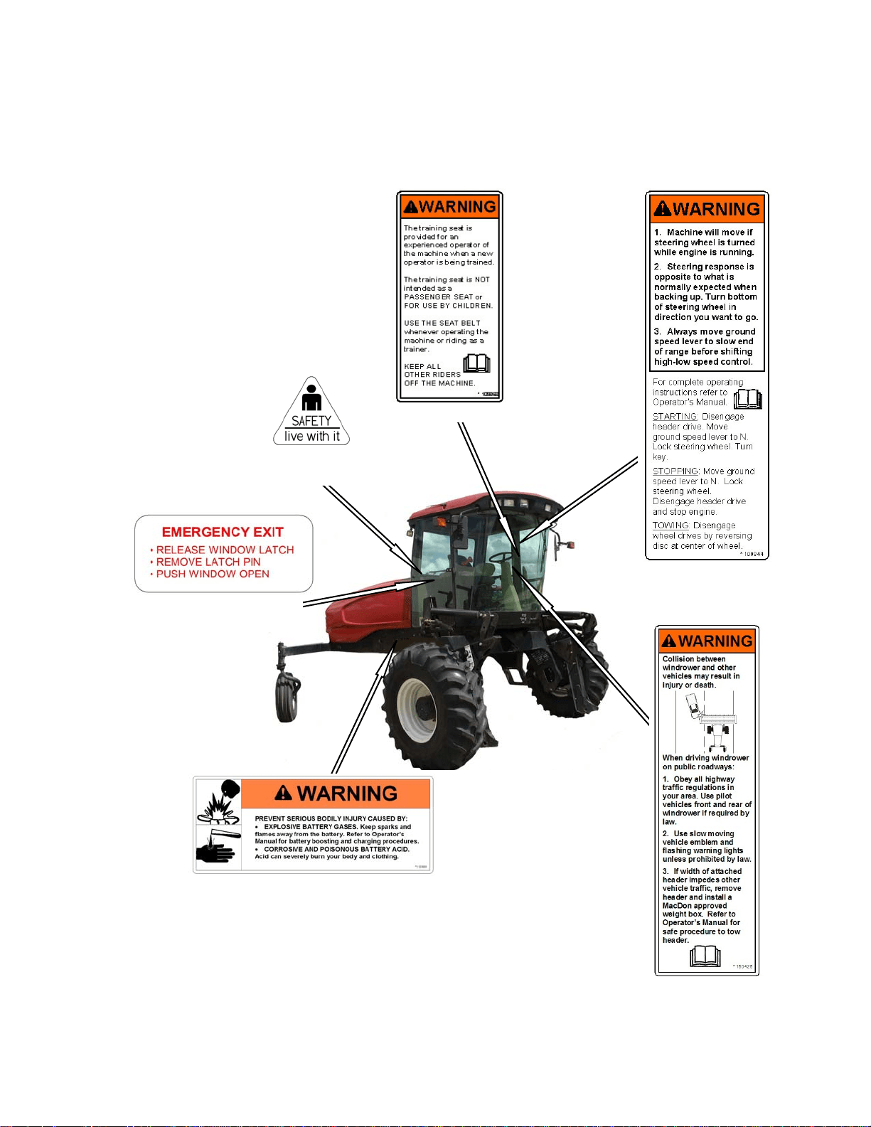
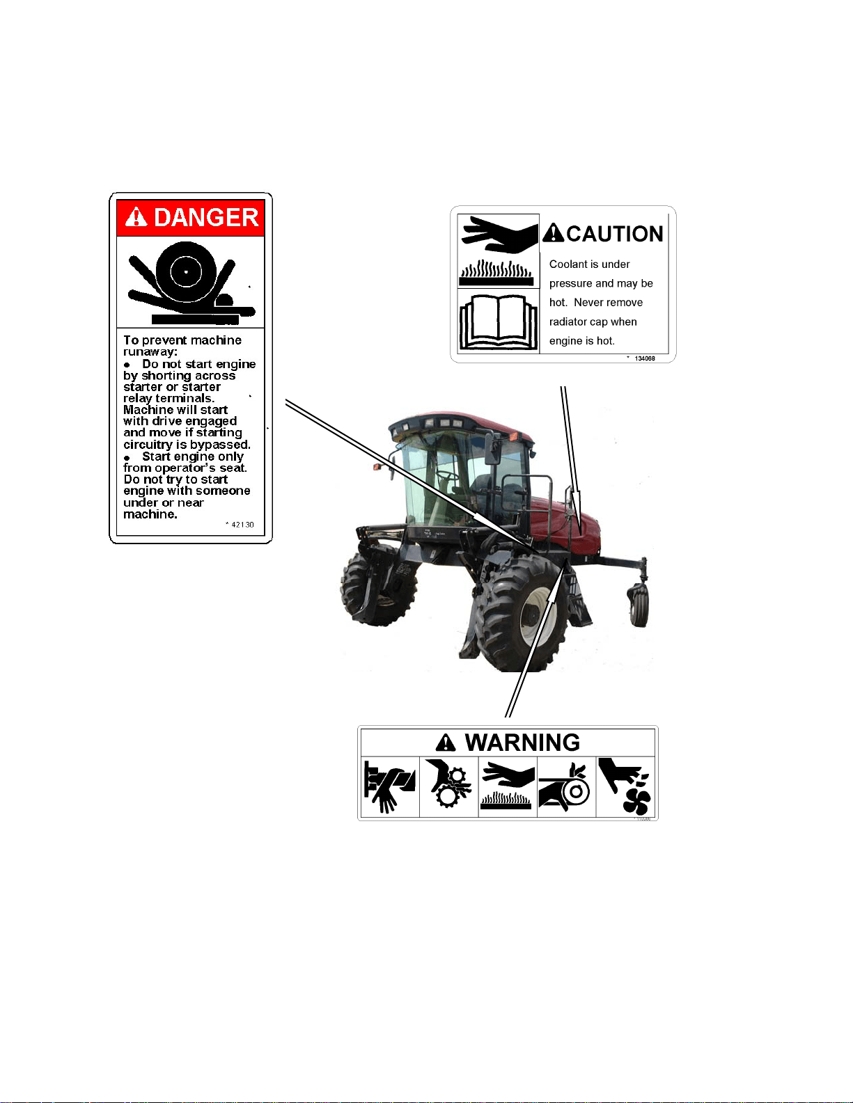
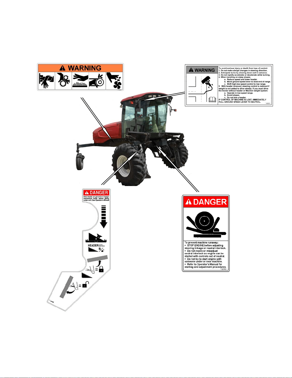
2.3.2 Safety Sign Locations
The safety signs (decals) appear on the
windrower at the locations approximately as
shown.
a. Keep safety signs clean and legible at all times.
b. Replace safety signs that are missing or become
illegible.
c. If original parts on which a safety sign was
installed are replaced, be sure the repair part
also bears the current safety sign.
d. Safety signs are available from your Dealer
Parts Department.
SAFETY
169304 6 Rev. C
Safety Sign Locations
(continued)
#32744 IN CAB
#109843 BEHIND DOOR
#163561 LIFT LINKAGES
#134070 FRONT OF PLATFORM
#160400 BEHIND DOOR
#32744 BELOW DOOR HANDLE
#44944 OIL RESERVOIR UNDER HOOD
SAFETY
169304 7 Rev. C
Safety Sign Locations (continued)
#109844 IN CAB
#109868 IN CAB
#32744 IN CAB
ABOVE WINDOW LATCH
#160426 IN CAB
#110989 ON FRAME
#160350 IN CAB
BESIDE WINDOW LATCH
SAFETY
169304 8 Rev. C
Safety Sign Locations
(continued)
#42130 ON FRAME
#134068 ON FAN SHROUD
#110986 ON FRAME
SAFETY
169304 9 Rev. C
Safety Sign Locations (continued)
#32743 INSIDE FRAME
#163562 ON LIFT LINKAGE
#160351 RH HEADLINER PANEL
#110986 ON FRAME

SAFETY
169304 10 Rev. C
2.4 GENERAL SAFETY
CAUTION
The following are general farm safety
precautions that should be part of your
operating procedure for all types of
machinery.
• Protect yourself.
• When assembling, operating and
servicing machinery, wear all the
protective clothing and personal
safety devices that COULD be
necessary for the job at hand. Don't
take chances.
• You may need:
• a hard hat.
• protective shoes with slip
resistant soles.
• protective glasses or goggles.
• heavy gloves.
• wet weather gear.
• respirator or filter mask.
• hearing protection. Be aware that
prolonged exposure to loud noise
can cause impairment or loss of
hearing. Wearing a suitable
hearing protective device such as
ear muffs (A) or ear plugs (B)
protects against objectionable or
loud
noises.
A
B
• Provide a first-aid kit for use in case of
emergencies.
• Keep a fire extinguisher on the machine.
Be sure the extinguisher is properly
maintained and be familiar with its proper
use.
• Keep young children away from
machinery at all times.
• Be aware that accidents often happen
when the operator is tired or in a hurry to
get finished. Take the time to consider
the safest way. Never ignore warning
signs of fatigue.
• Wear close-fitting
clothing and cover
long hair. Never wear
dangling items such
as scarves or
bracelets.
• Keep hands, feet,
clothing and hair
away from moving parts. Never attempt
to clear obstructions or objects from a
machine while the engine is running.

SAFETY
169304 11 Rev. C
• Keep all shields in place. Never alter or
remove safety equipment. Make sure
driveline guards can rotate
independently of the shaft and can
telescope freely.
• Use only service and repair parts made
or approved by the equipment
manufacturer. Substituted parts may not
meet strength, design, or safety
requirements.
• Do not modify the machine. Unauthorized
modifications may impair the function
and/or safety and affect machine life.
• Stop engine and remove key from
ignition before leaving operator's seat for
any reason. A child or even a pet could
engage an
idling
machine.
• Keep the area
used for
servicing
machinery
clean and
dry. Wet or
oily floors are
slippery. Wet
spots can be
dangerous when working with electrical
equipment. Be sure all electrical outlets
and tools are properly grounded.
• Use adequate light for the job at hand.
• Keep machinery clean. Straw and chaff
on a hot engine are a fire hazard. Do not
allow oil or grease to accumulate on
service platforms, ladders or controls.
Clean machines before storage.
• Never use gasoline, naphtha or any
volatile material for cleaning purposes.
These materials may be toxic and/or
flammable.
• When storing machinery, cover sharp or
extending components to prevent injury
from accidental contact.

ACRONYMS AND ABBREVIATIONS
169304 12 Rev. C
3 ACRONYMS AND
ABBREVIATIONS
TERM DEFINITION
API
American Petroleum Institute
ASTM
American Society Of Testing And
Materials
cc cubic centimeters
C
Celsius
CDM
Cab Display Module
F
Fahrenheit
ft/min feet per minute
ft/s feet per second
gpm U.S. gallons per minute
GSL
Ground Speed Lever
hp horsepower
in. inches
in
3
cubic inches
kg
kilograms
kPa
kilopascals
lbf.
pounds force
lbf.ft or ft·lbf
pound feet or foot pounds
lbf.in or in·lbf pound inches or inch pounds
L/min
liters per minute
mm
millimeters
mph
miles per hour
N
Newtons
N·m newton meters
N-DETENT
The slot opposite the neutral
position on operator’s console.
oz.
ounces
psi
pounds per square inch
rpm
Revolutions Per Minute
SAE Society Of Automotive Engineers
SCA Supplemental Coolant Additives
WCM
Windrower Control Module
Also See Section 7.3.3 Conversion Chart.
SPECIFICATIONS
169304 13 Rev. C
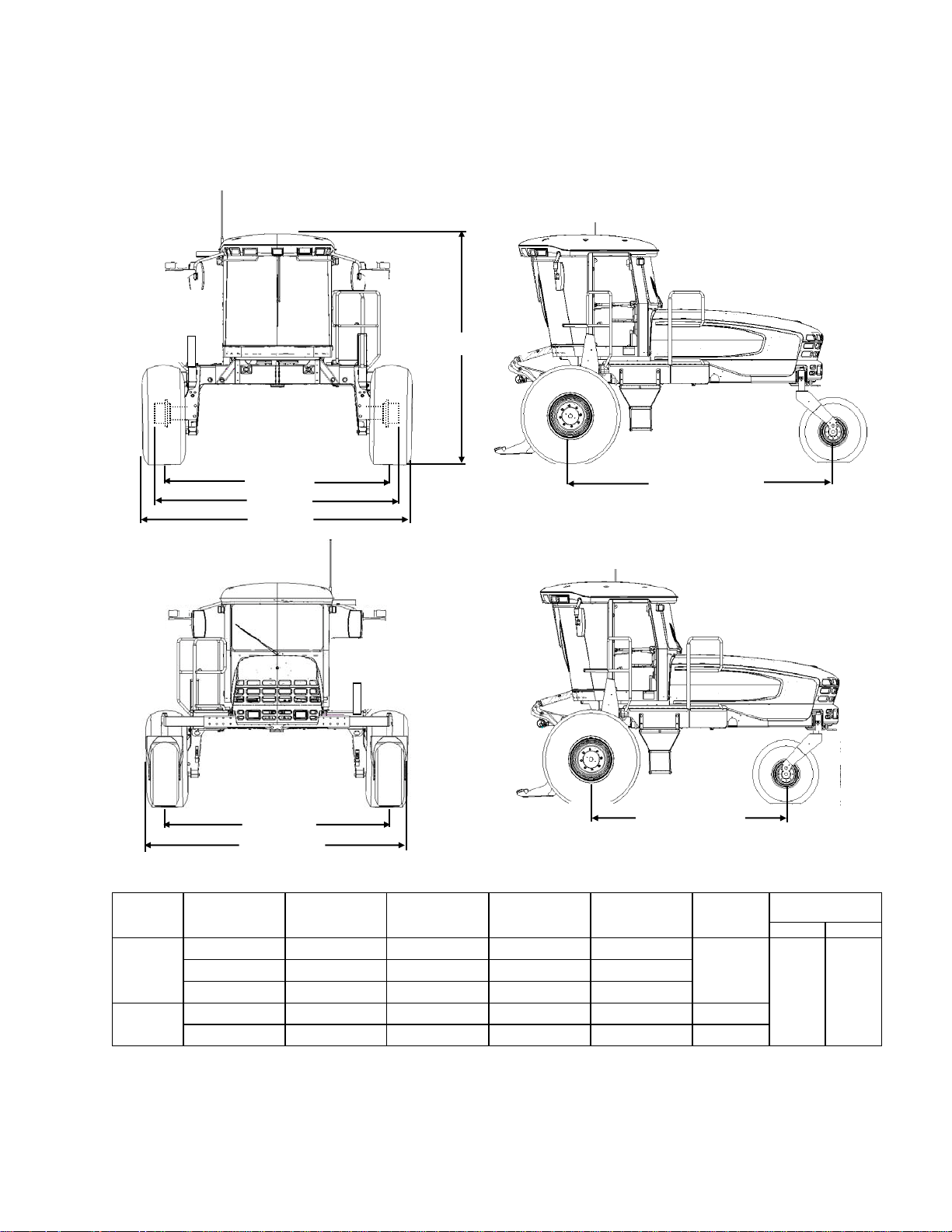
4 SPECIFICATIONS
4.1 WINDROWER DIMENSIONS
WHEEL
POSITION
TREAD
Inch (mm)
HUBS
Inch (mm)
CASTERS
Inch (mm)
TIRES
Inch (mm)
SHIPPING
Inch (mm)
WHEEL BASE
Inch (mm)
FWD REV
DRIVE
TIRE
Inner/Outer - 138.7 (3522) - -
142.9
(3630)
158.3
(4021)
120.7
(3066)
Outer/Outer 134.2 (3410) 146.1 (3712) - 157.1 (3990)
Inner/Inner 120.1 (3050) 131.6 (3342) - 150.0 (3810)
CASTER
TIRE
Minimum 93.2 (2367) - 115.4 (2932) - -
Maximum 135.8 (3448) - 158.0 (4013) - -
NOTE: Above dimensions are with 18.4 - 26 drive tires and forked casters.
TREAD
CASTERS
45.7 in. (1160
TREAD
HUBS
TIRES
WHEEL BASE
133 in. (3378 mm)
WHEEL BASE

SPECIFICATIONS
169304 14 Rev. C
4.2 SPECIFICATIONS
ENGINE
Type
Cummins QSB-3.3 4 Cyl. Turbo
Displacement
200 cu. in. (3.3liters)
Power
Rated
99 hp (74 kW) @ 2600 rpm
Peak
99 hp (74 kW) @ 2000 rpm
Maximum RPM (no load)
2630-2650
Idle RPM
1100
ELECTRICAL SYSTEM
Recommended Battery
Group Rating 31A. Max Dim – 13L.x6.81W.x9.43H. in. (330x173x240 mm).
12 Volt, Min. 950CCA Heavy Duty/Off Road/Vibration Resistant.
Alternator
120 amp
Starter
Dry Type
Working Lights
11
TRACTION DRIVE
Type
Hydrostatic, 2 Speed Electric Shift
Speed
Field
Lo Range 0-11 mph (17.7 km/h)
Reverse
6 mph (9.6 km/h)
Transport
High Range 0-16 mph (25.6 km/h)
Transmission
Type
2 Piston Pumps – 1 per Drive Wheel.
Displacement
3.0 cu.in. (49 cc)
Flow
33 U.S. gpm (129 L/min)
Final Drive
Type
Planetary Gearbox
Ratio
41.42 : 1
Wheel Motor Displ.
Lo Range
2.8 cu.in. (46 cc)
Hi Range
1.7 cu.in. (27 cc)
SYSTEM CAPACITIES
Fuel Tank
97 U.S. Gallons (378 liters)
Cooling
5.1 U.S. Gallons (20 liters)
Hydraulic Reservoir
11.5 U.S. Gallons (45 liters)
Crankcase
1.9 U.S. Gallons (7 liters)
HEADER DRIVE
Type Displacement Flow Max. Press.
Knife Drive – Pump A (Mechanically Adjustable) Piston
3.0 cu.in.
(0-49 cc)
0-30 U.S. gpm (117
L/min)
4000 psi
(27579 kPa)
Reel Drive – Pump B
Gear
1.02 cu.in.
(16.7 cc)
0-11.5 U.S. gpm (45
L/min) @ 2600 rpm
2600 psi
(17926 kPa)
Conveyor – Pump C
(continued next page)

SPECIFICATIONS
169304 15 Rev. C
HEADER LIFT/TILT
Type
Hydraulic
Gear Pump
Displacement 1.02 cu.in. (16.7 cc)
Flow 11.5 U.S. gpm (46.5 L/min)
System Pressure (Relief/Max)
2500 psi (17.24 MPa)
Header Tilt
Mechanically Adjustable Link (Optional Hydraulic Cylinder Adjustable From
Cab
)
HEADER FLOTATION
Adjustable Springs
Manual, External, Draw-Bolt With Springs (1 per side)
CAB
Dimensions
Width
63 in. (1600 mm)
Depth
68.3 in. (1735 mm) (at top of window)
Height
64.6 in. (1640 mm)
Volume
125 cu.ft. (3540 liters)
Seat
Driver
Mechanical Suspension, Seat Belt
Training
(
Optional
)
Folding, Cab Mounted, Seat Belt
Windshield Wiper
Front
31.5 in. (800 mm) Blade
Heater 24,000 Btu/h (7038 W)
Air Conditioning 28,280 Btu/h (8288 W)
Electrical Outlets One Live, One On Ignition, One Live/Keyed.
Mirrors Two Outside
Radio
Two Speakers and Antenna Factory Installed.
Dealer Installed Radio
SYSTEM MONITORING
Speeds
Ground (mph or km/h), Engine (rpm), Knife (spm) Optional, Reel (rpm)
Optional, Conveyor (Ref. No.)
Header Height, Angle (Optional)
TIRE OPTIONS
Size
Drive
18.4 - 26 Bar, 18.4 - 26 Turf, 600-65 R28 Bar, 23.1 - 26 Turf, 580-70 R26 Turf
Rear
7.5 – 16SL Single Rib Formed Caster, 10 x 16 Formed/Forked Caster
16.5L – 16.1 Rib Implement Flotation, Forked Caster
Pressure
Drive
Bar – 32 psi (221 kPa), Turf – 20 psi (138 kPa)
Rear
10 psi (69 kPa)
FRAME AND STRUCTURE
Dimensions Refer to Section 4.1, Windrower Dimensions
Frame to Ground (Crop Clearance) 45.7 in. (1160 mm)
Weight Approx. 9900 lb (4491 kg)
NG Header Compatibility
SK
A30S Auger, D50 & D60S Harvest Header (35’ Max.)
DK
A30D, A40D Auger, D60D Harvest Header (35’ Max.)
NOTES: 1. Specifications and design are subject to change without notice or obligation to revise previously
sold units.
2. Weights do not include options.
OPERATOR’S STATION
169304 16 Rev. C
5 OPERATOR’S STATION
The operator’s station is designed for operating
the windrower in a cab forward mode.
5.1 OPERATOR CONSOLE
The console contains controls to operate the
windrower as well as amenities for the operator.
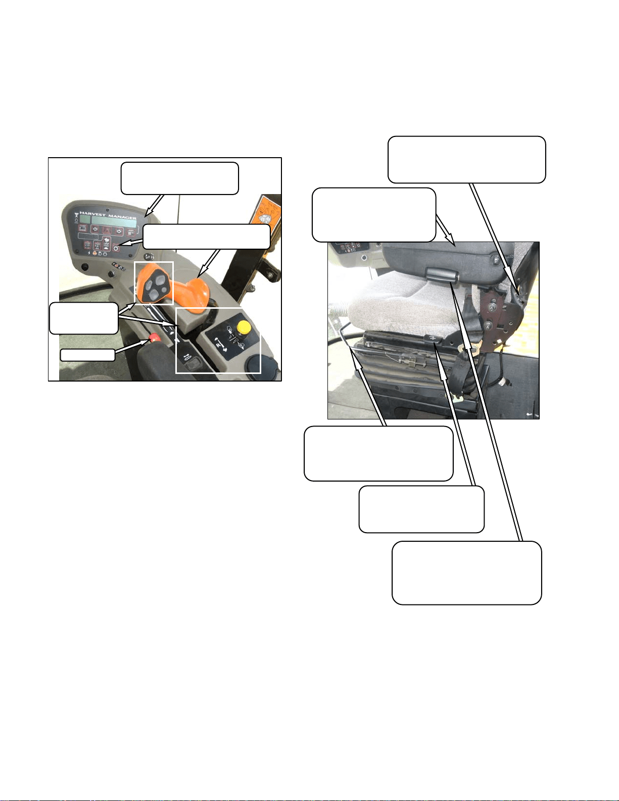
5.2 SEAT ADJUSTMENTS
The operator’s seat has several adjustments.
Refer to the following illustration for the location
and description of each adjustment.
LUMBAR SUPPORT
Adjusts Stiffness of Seat Back
INCREASE - Rotate Knob Upward.
DECREASE - Rotate Knob Downward.
ARM REST ANGLE
Adjusts Angle of Arm Rest
INCREASE - Rotate Knob Clockwise.
DECREASE - Rotate Knob Counter-
Clockwise.
SEAT FORE-AFT POSITION
Adjusts Fore-Aft Position
Pull Lever Up To Release.
Move Seat Forward or Rearward.
Release Lever.
SEAT BACK ANGLE
Pull Lever Up To Release.
Position Seat Back As Desired.
Release Lever.
ARM REST
Raise Arm Rest For Easier
Access To Seat.
Lower Arm Rest After Seat
Belt Is Buckled.
THROTTLE
HEADER
CONTROLS
SECTION 5.16
ENGINE/WINDROWER CAB
DISPLAY MODULE (CDM)
SECTION 5.17
GROUND SPEED CONTROLS
SECTION 5.15
OPERATOR’S STATION
169304 17 Rev. C
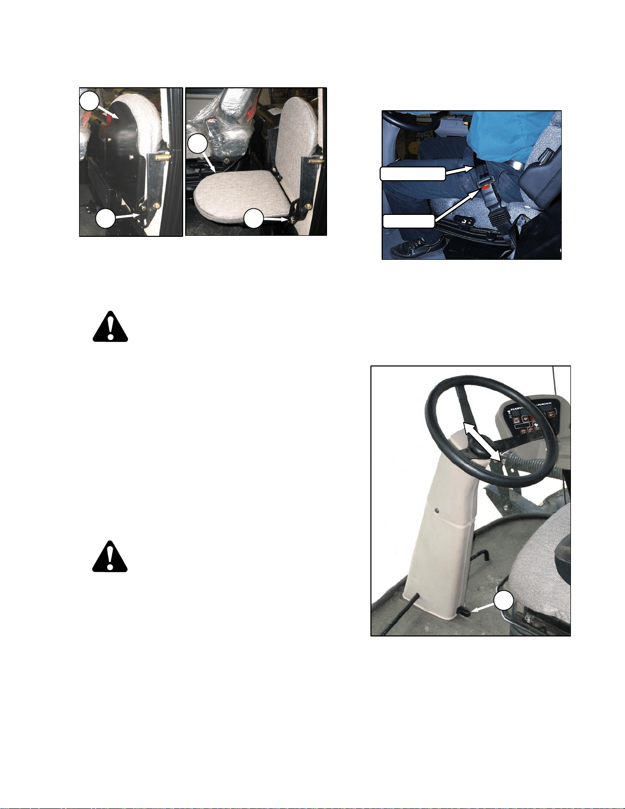
5.3 TRAINING SEAT (Optional)
A wall mounted fold-up training seat complete
with seat belt is provided for use as described
below. To lower seat, lift latch (A) and lower
seat (B). For storage, lift seat (B) and secure
with latch (A).
WARNING
The training seat is provided for an
experienced operator of the machine when a
new operator is being trained.
The training seat is NOT intended as a
PASSENGER SEAT or FOR USE BY
CHILDREN.
USE THE SEAT BELT whenever operating
the machine or riding as a trainer.
KEEP ALL OTHER RIDERS OFF THE
MACHINE.
5.4 SEAT BELTS
The windrower is equipped with a seat belt on
the Operator’s and Trainer’s seats.
WARNING
• Before starting engine, securely fasten
your seat belt and ensure trainer’s seat
belt is fastened if occupied. The seat belt
can help insure your safety if it is used
and maintained.
• Never wear a seat belt loosely or with
slack in the belt system.
• Never wear the belt in a twisted condition
or pinched between the seat structural
members.
a. To fasten seat belt, pull belt completely across
your body. Push the metal eye into the buckle
until it locks. Adjust the position of the belt as
low on your body as possible.
b. To release, push the red button in the end of the
buckle and separate the buckle and metal eye.
5.5 STEERING COLUMN ADJUSTMENT
The steering column can be adjusted to suit
each particular operator and for easier entry to
and exit from the seat.
a. Hold onto steering wheel, step on lever (C), and
move steering wheel up or down to desired
position.
b. Release lever (C) to lock steering wheel
position.
RELEASE
SEAT BELT
C
A
B
A
B

OPERATOR’S STATION
169304 18 Rev. C
5.6 OPERATOR PRESENCE
The Operator Presence System is a safety
feature that is designed to deactivate or alarm
selected systems when the operator is not
seated at the operator’s station. These systems
include:
• Header Drive
• Transmission
• Engine
5.6.1 Header Drive
• Requires the operator to be seated in the
seat in order to engage the header drive.
• Power is maintained to the header drive for
5 seconds after the operator leaves the seat,
and then the header shuts down.
• If the seat switch is open for more than 5
seconds and the seat switch is closed again,
it requires the operator to move the header
engage switch to “OFF” position and back to
the “ON” position again to restart the
header.
5.6.2 Transmission
• If the operator leaves the seat and the
transmission is not locked in neutral, after 2
seconds the lower display will flash “NOT IN
NEUTRAL” accompanied by an alarm.
5.6.3 Engine
• The engine will not be allowed to start when
the header drive switch is engaged.
• The engine will not be allowed to start when
the transmission is not locked in neutral.
• The engine will shutdown when the
windrower is moving at 5 mph (8 km/h) or
less and the operator leaves the seat.
OPERATOR’S STATION
169304 19 Rev. C
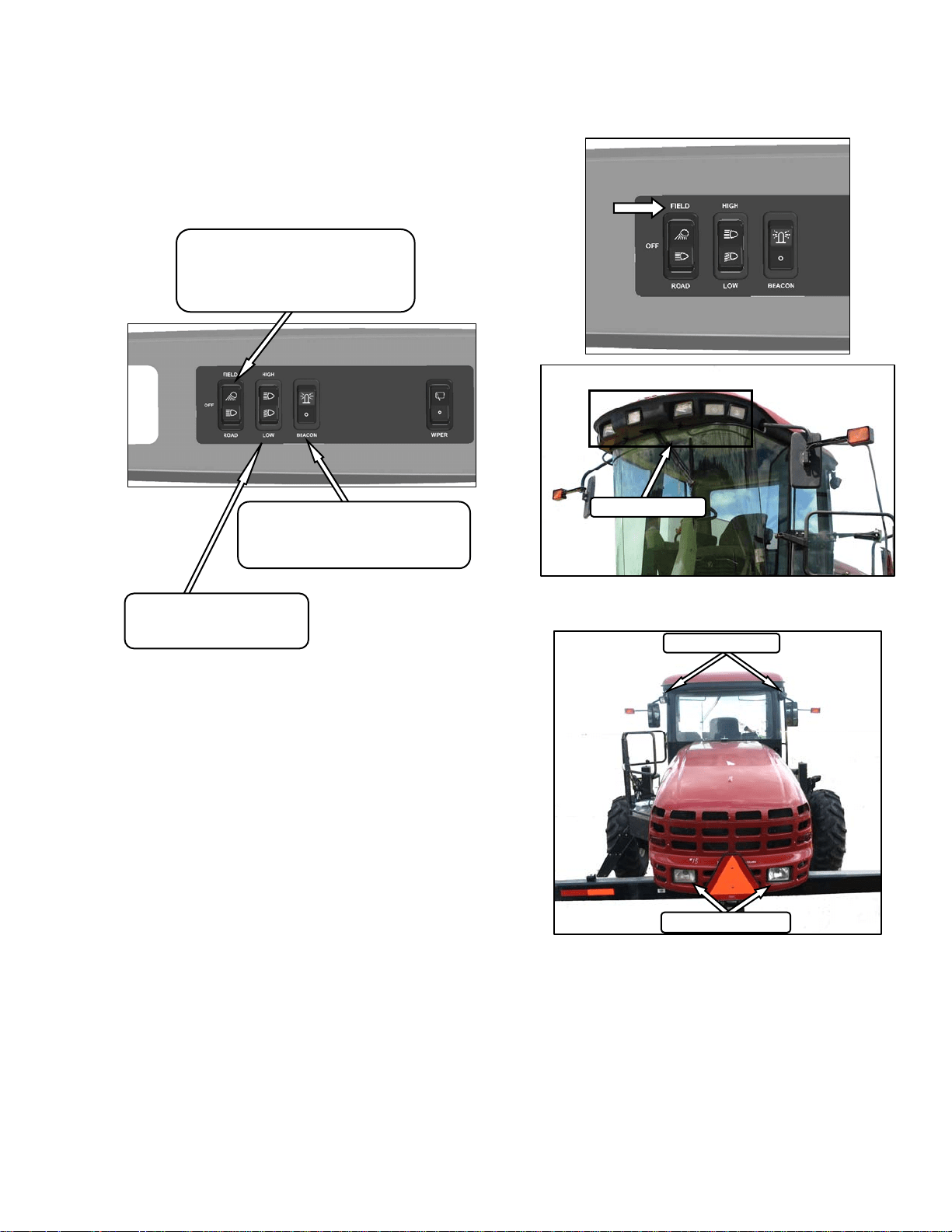
5.7 LIGHTS
The field and transport light switches are located
on a panel in the cab headliner. Refer to
illustrations on following pages for location of
lights.
5.7.1 Field Lighting
HI/LO LIGHTS
Controls Hi/Lo Beam For
Road Lights On Cab Roof
LIGHTS SWITCH
Controls Field and Transport Lights
FIELD
OFF
ROAD
BEACON
Controls Beacons On Cab.
Standard for Export. Optional for N.A.
On – Off
REAR
FIELD LIGHTS
SWATH LIGHTS
FRONT
FIELD LIGHTS
OPERATOR’S STATION
169304 20 Rev. C
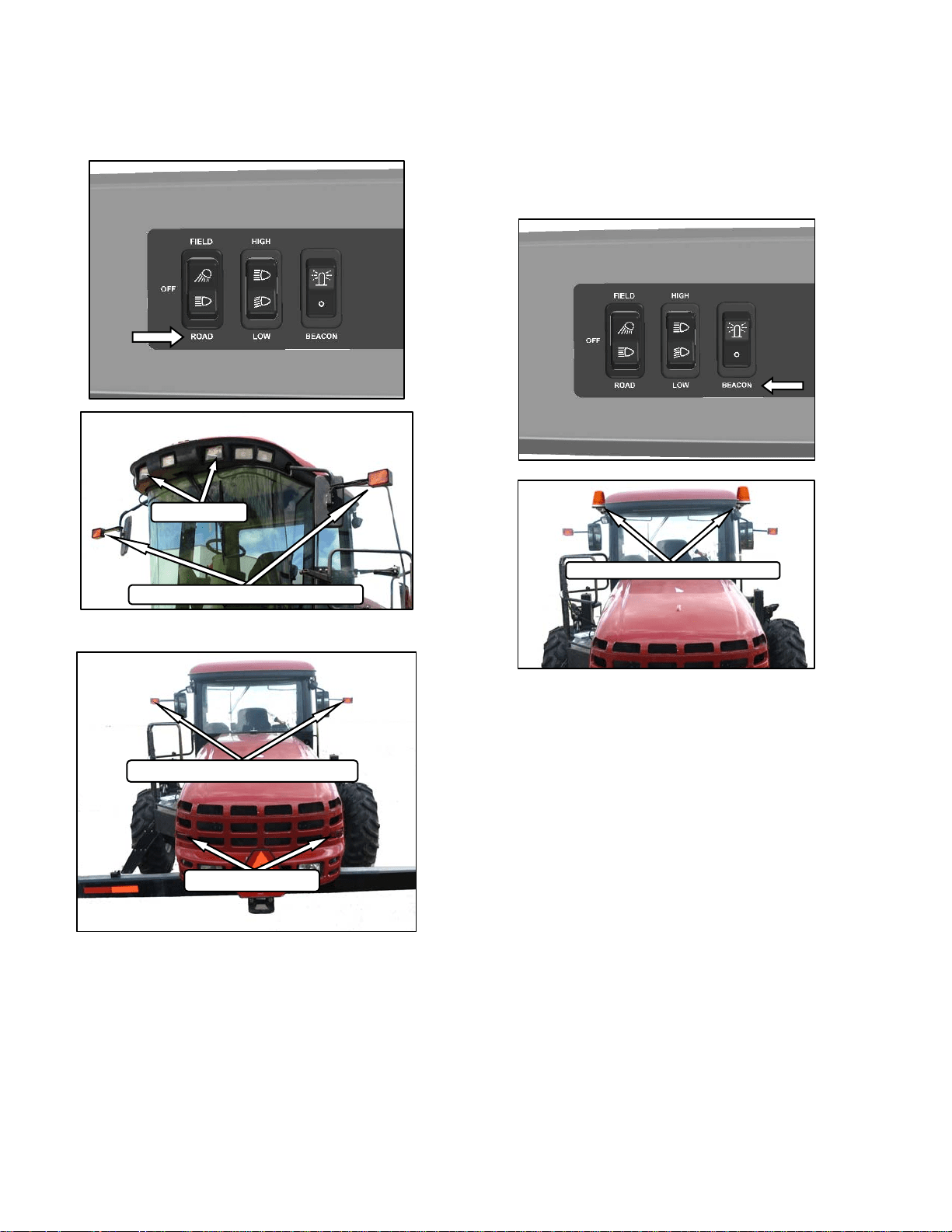
5.7.2 Road Lighting
5.7.3 Beacon Lighting – Export
The beacon lights are functional when the
ignition and the beacon switches are on. The
beacons must be used when driving on the road.
BEACON LIGHTS - AMBER
REAR
TAIL LIGHTS - RED
TURN SIGNALS/HAZARDS - AMBER
FRONT
TURN SIGNALS/HAZARDS - AMBER
HI/LO LIGHTS
OPERATOR’S STATION
169304 21 Rev. C
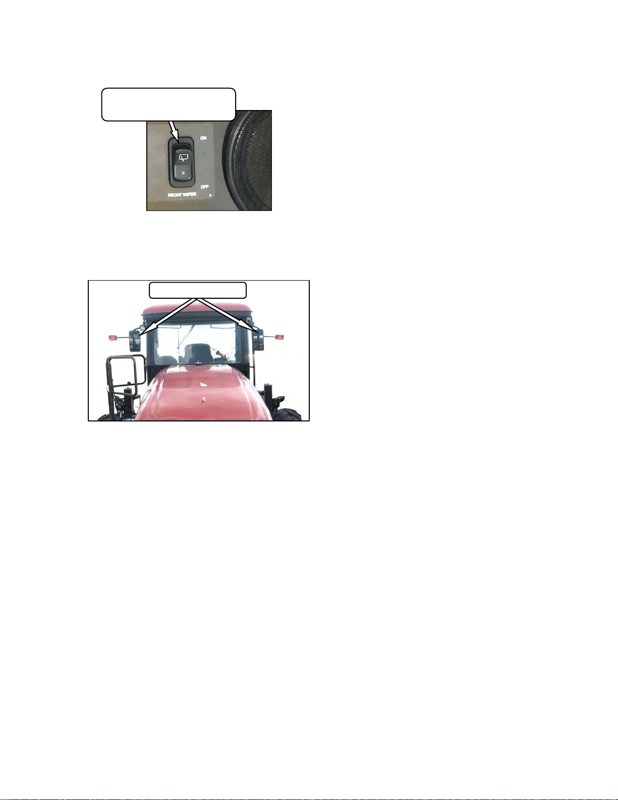
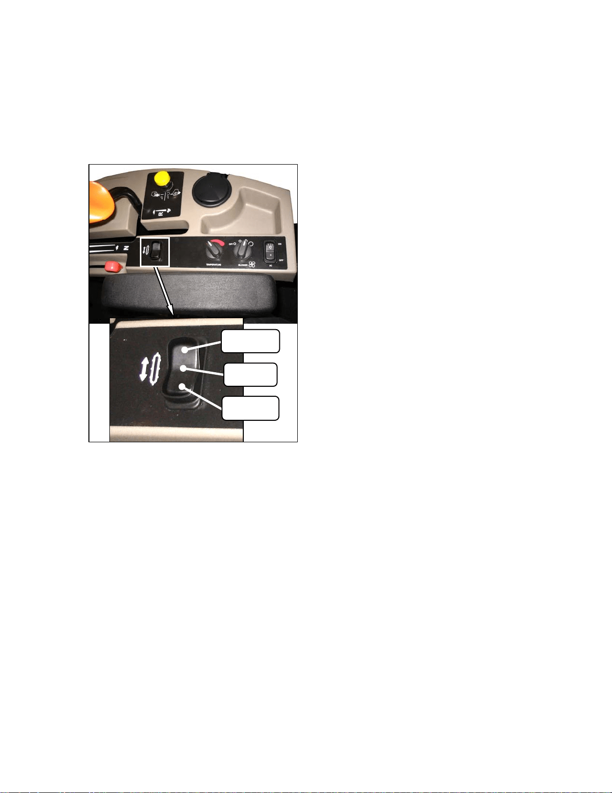
5.8 WINDSHIELD WIPERS
The windshield wiper control is located in the
cab headliner.
5.9 REAR VIEW MIRRORS
Two adjustable outside mounted mirrors provide
rear view vision.
REAR VIEW MIRRORS
WIPER SWITCH
Controls Windshield Wiper
ON/OFF
OPERATOR’S STATION
169304 22 Rev. C
5.10 CAB TEMPERATURE
The cab environment is controlled by a climate-
control system that provides clean air-
conditioned or heated air for the operator. The
heater/evaporator/blower assembly is located
under the cab floorboard and is accessible from
beneath the windrower.
5.10.1 Controls
Refer to the following illustrations for an
explanation of the controls and operating
procedures.
IMPORTANT
To distribute the oil throughout the
system, perform the following steps
whenever the machine is first started after
storage for more than one week:
a. Ensure heater shut-off valve at engine is open.
See 5.10.3 Heater Shut-off Valve.
b. Turn blower switch to the first position, turn
temperature control switch to maximum heating,
and A/C control to “OFF”.
c. Start engine and operate at low idle until engine
is warm.
d. Click A/C switch from "OFF" to "ON" for one
second, then back to "OFF" for 5 to 10 seconds.
Repeat this step ten times.
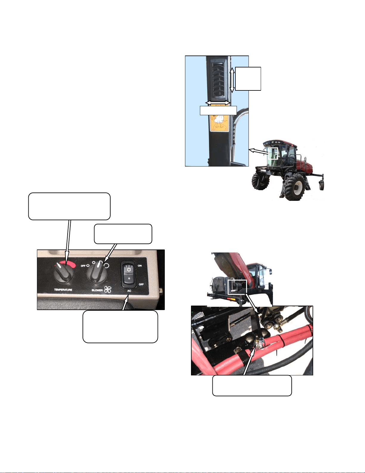
5.10.2 Air Distribution
Cab air distribution is controlled through
adjustable air vents. They are located in the cab
posts to provide window and operator ventilation
as shown in illustration.
5.10.3 Heater Shut-Off Valve
A shut-off valve at the engine allows the cab
heater to be isolated from the engine coolant.
The valve must be open to provide heat to the
cab but for maximum cooling, the valve can be
closed.
HEATER SHUT-OFF VALVE
OPEN – Counterclockwise
CLOSE - Clockwise
TEMPERATURE CONTROL
Controls Cab Temperature
INCREASE – Clockwise
DECREASE - Counter-Clockwise
BLOWER SWITCH
Controls Blower Speed
OFF/LO/MEDIUM/HI
AIR CONDITIONING SWITCH
Controls A/C System
OFF - A/C Does Not Operate.
ON - A/C Operates With Blower
Switch On.
OPEN
CLOSE
DIRECTION
OPERATOR’S STATION
169304 23 Rev. C
5.10.4 A/C Compressor Protection
The compressor is protected from excessively
low and high pressures by two switches that
shut down the compressor to prevent damage to
the system.
• The LOW pressure switch opens when the
pressure falls to 5.1-10.9 psi (35-75 kPa)
and shuts down the compressor. When the
pressure rises to 17.6-26.4 psi (121-182
kPa), the switch closes and allows the
compressor to run.
• The HIGH pressure switch opens and stops
the compressor when the pressure rises to
315-335 psi (2172-2310 kPa). When the
pressure falls to 220-280 psi (1517-1930
kPa), the switch closes and allows the
compressor to run.
• The Windrower Control Module (WCM)
gives a warning when it senses rapid
pressure changes that cause the
compressor to rapidly engage and
disengage.
If the air conditioning system is shut down by
either switch, locate the source of the problem
and correct it before operating the system.
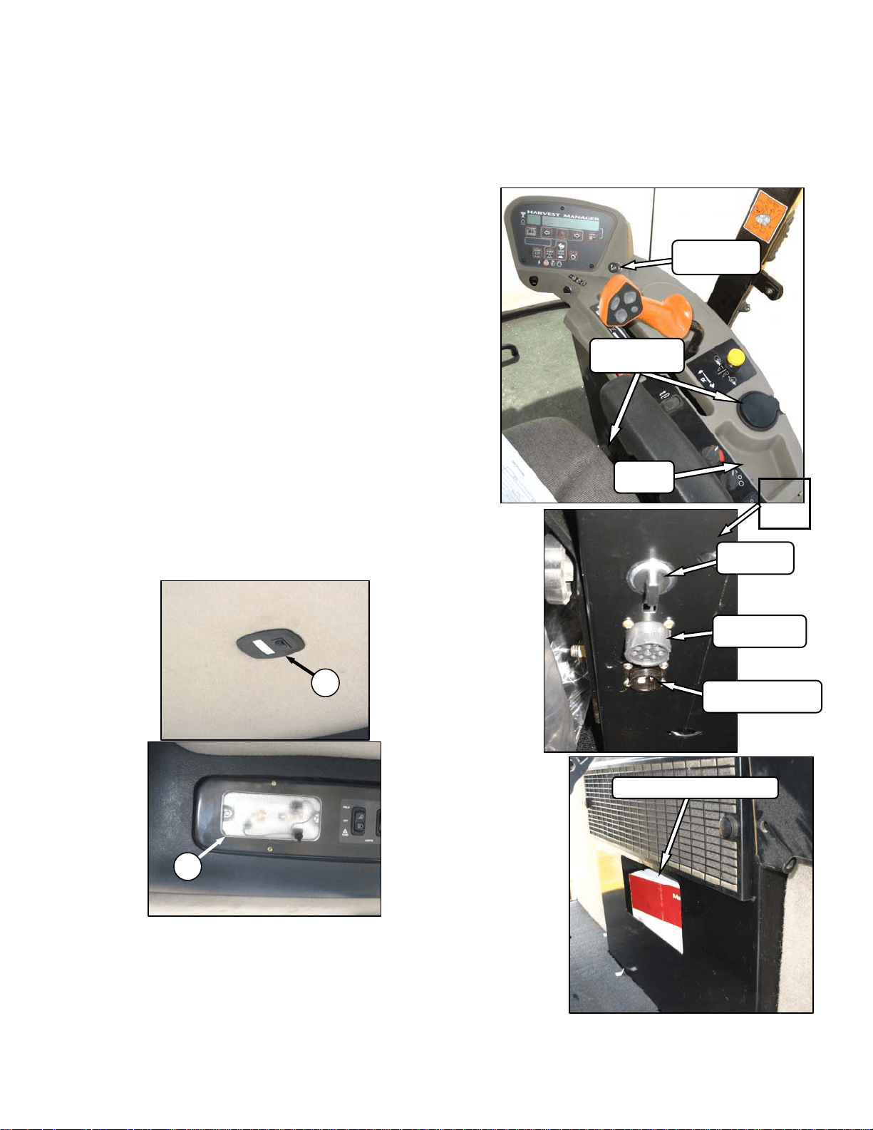
5.11 INTERIOR LIGHTS
Two interior lights are installed in the cab
headliner. A low intensity LED light (A) is
located directly overhead to provide ambient
lighting if desired, and functions only when the
road/field light switch is on. An on-off switch is
located on the light.
The other interior light (B) is located on the
headliner switch panel and the push-on, push-off
button is located on the light.
5.12 OPERATOR AMENITIES
A
B
MANUAL STORAGE CASE
CIGARETTE
LIGHTER
AUXILIARY
POWER
DATA LINK
RECEPTACLE
LIVE/SWITCHABLE
/GROUND – 20 A.
ASHTRAY/
CUPHOLDERS
UTILITY
TRAY
OPERATOR’S STATION
169304 24 Rev. C
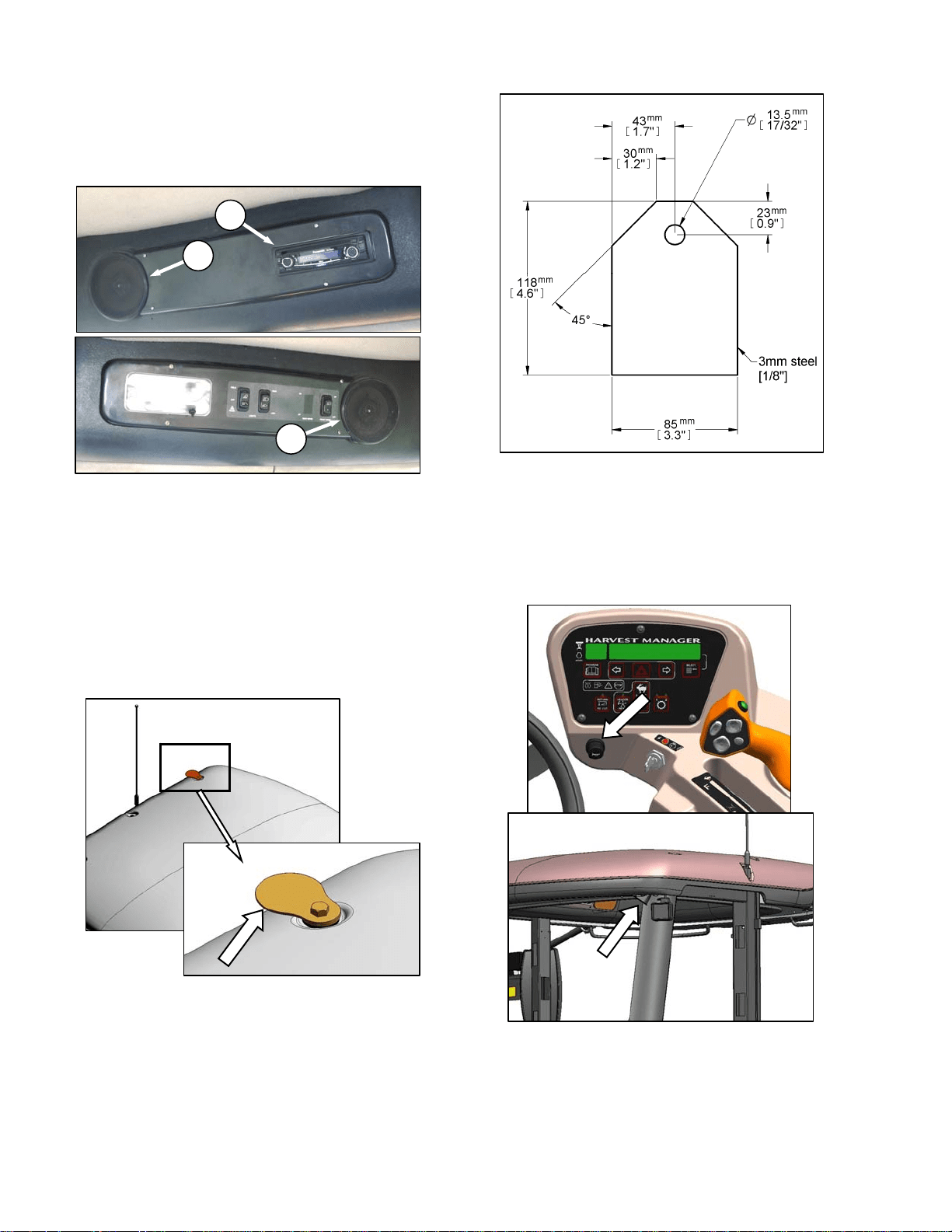
5.13 RADIOS
5.13.1 AM/FM Radio
A radio (A) is available as optional equipment
from your dealer and a space is provided in the
cab headliner to accommodate the installation.
Two pre-wired speakers (B) have been factory
installed in the headliner. Refer to M100 Self-
Propelled Windrower Unloading and Assembly
Instruction for radio installation procedures.
Operating instructions are supplied with the
radio.
5.13.2 Antenna Mounting
A roof mounted antenna base for installing a
magnetic antenna is available as an option from
your dealer. Order part #160288, or see
illustration for part dimensions for a “homemade”
version. It accommodates most CB, 2-way radio
and satellite radio antennas. Refer to M100
Self-Propelled Windrower Unloading and
Assembly Instruction for installation procedures.
IMPORTANT
Antenna base can only be installed on the
LH and RH rear cab roof bolts.
5.14 HORN
The horn is activated by pushing the button
located beside the ignition key. The ignition
switch must be on. Sound the horn three times
prior to starting the engine.
11 GA. OR 3.0 mm CQHRS
A
B
B
OPERATOR’S STATION
169304 25 Rev. C
5.15 ENGINE CONTROLS/GAUGES
All engine controls are conveniently located on
the operator’s console. Refer to the following
illustration for the location and a description of
each.
THROTTLE
Controls Engine RPM.
FULL – Push Lever Forward
OPERATING – See Section 6.3.5
IDLE – Pull Lever Back
IGNITION SWITCH
ACC – Fully Counter-Clockwise
OFF – All Electrical Systems Off
RUN – Clockwise
START– Fully Clockwise To Crank Engine
Release and Switch Returns to RUN
REMOVE KEY WHEN WINDROWER NOT IN USE.
KEY ALSO LOCKS DOORS.
FULL
IDLE
OPERATOR’S STATION
169304 26 Rev. C
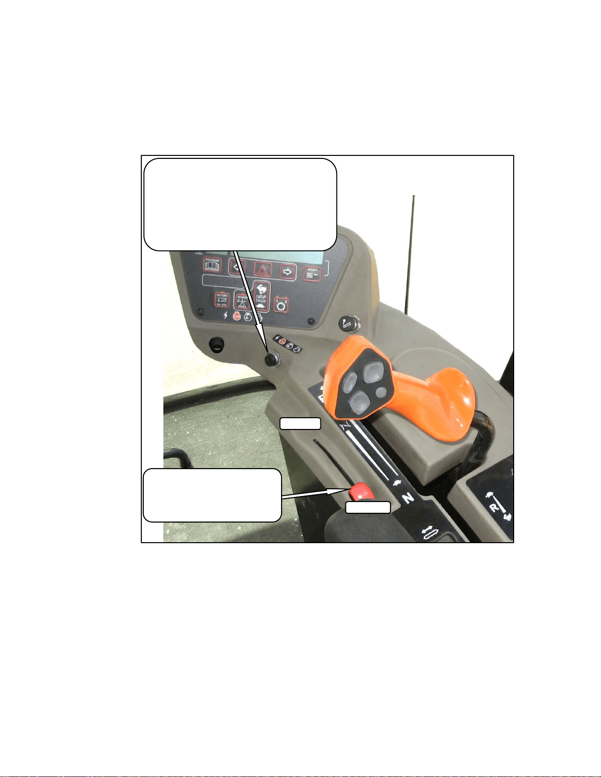
5.16 WINDROWER CONTROLS
HAZARD WARNING LIGHTS
Activates Signals On Windrower and Header
Push On – Push Off
FAST
SLOW
GROUND SPEED LEVER (GSL)
Controls Speed and Direction of Movement
F – Forward
N – Neutral
N-DETENT – Engages Neutral Interlock and Applies
Park Brake When Steering Locked In Center
R - Reverse
N-DETENT
TURN SIGNALS
Activates Turn Signals On Windrower and Header
Push On – Push Off
REVERSE
OPERATOR’S STATION
169304 27 Rev. C
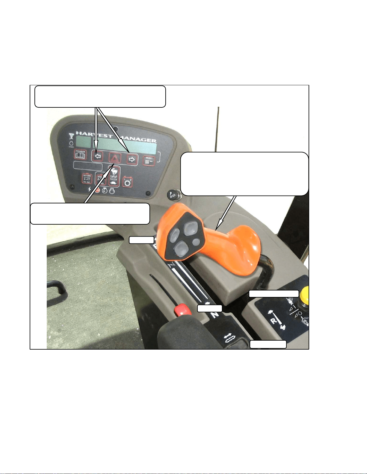
5.17 HEADER CONTROLS
All header controls are conveniently located on
the operator’s console and on the GSL handle.
NOTE
Some controls are optional equipment and
may not be present in your unit. Some
controls may be installed, but will be non-
functional for certain headers.
5.17.1 Header Engage Switch
Engages and disengages header drive.
IMPORTANT
Always move throttle lever back to idle
before engaging header drive. Do not
engage header with engine at full RPM.
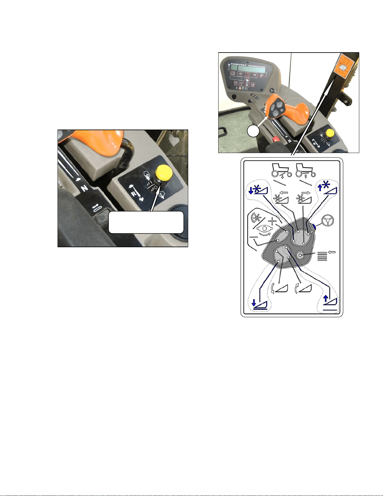
5.17.2 GSL Header Switches
The GSL (A) contains switches for the following
header functions that are most often adjusted
while in operation to suit changing crop
conditions. All are momentary type switches. A
decal that identifies the switch functions is
located on the cab post above the operator’s
console.
• Display Selector
• Reel Position
• Header Position
• Reel Speed
HEADER DRIVE
ENGAGE – Pull Up
DISENGAGE – Push Down
A
OPERATOR’S STATION
169304 28 Rev. C
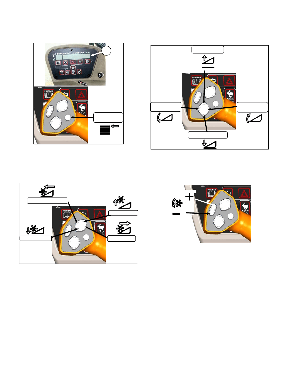
5.17.2.1 Display Selector Switch
Selects and displays the settings in the CDM (B)
top line read-out for each of the header controls.
• Press switch to scroll through settings.
5.17.2.2 Reel Position Switches
NOTE
Reel position switches work only on
draper headers.
Press and hold switch at location shown to move
reel.
Release switch at desired position.
5.17.2.3 Header Position Switches
Press and hold switch at location shown to move
header.
Release switch at desired position.
5.17.2.4 Reel Speed Switches
Press and hold switch at location shown to
change reel speed.
Release switch at desired speed.
NOTE
Auger speed adjusts proportionately when
reel speed is changed. See Section 6 for
further details.
DISPLAY
SELECTOR
B
REEL UP
REEL AFT
REEL FORWARD
REEL DOWN
HEADER
TILT UP
HEADER DOWN
HEADER
TILT DOWN
HEADER UP
SLOW
FAST
OPERATOR’S STATION
169304 29 Rev. C
5.17.3 Console Header Switches
The operator’s console contains switches for the
following header functions that are most often
used while the windrower is stationary.
5.17.3.1 Deck Shift
Draper Header with Deck Shift Option -
Controls deck shifting for double windrowing
options with a draper header.
CENTER
DELIVERY
LEFT SIDE
DELIVERY
RIGHT SIDE
DELIVERY
OPERATOR’S STATION
169304 30 Rev. C
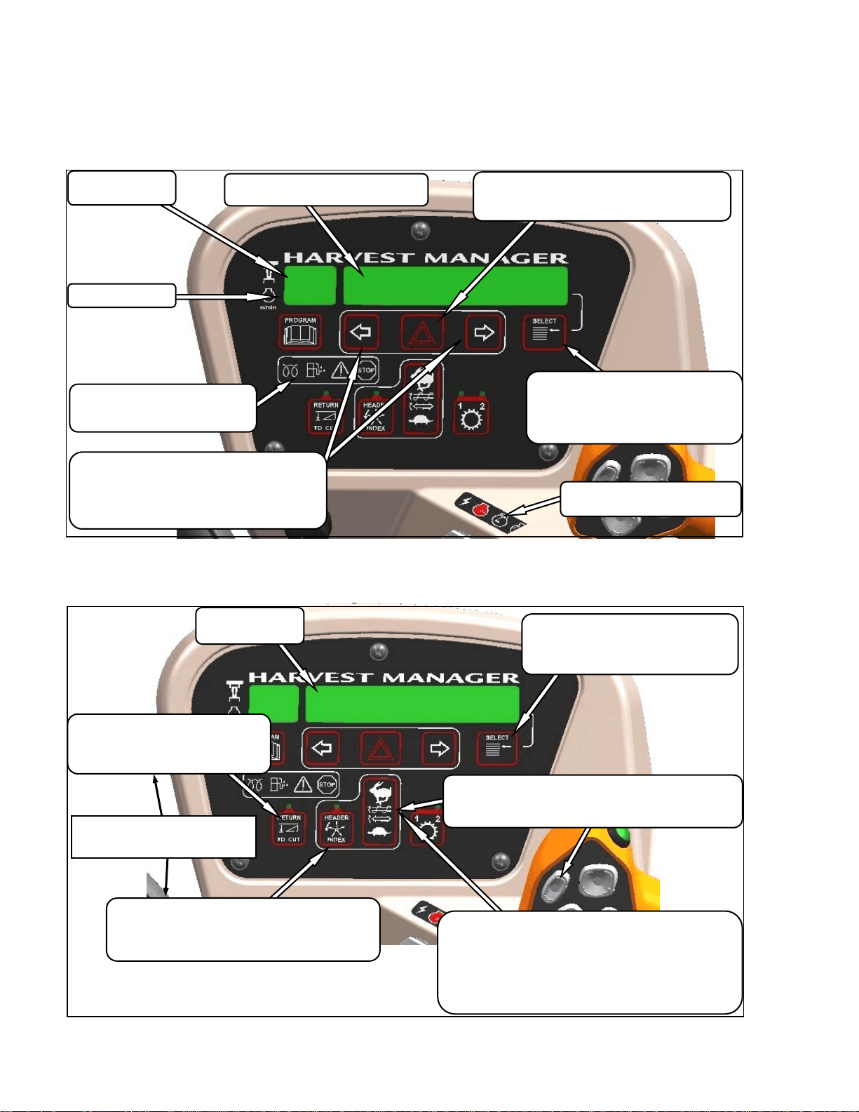
5.18 CAB DISPLAY MODULE (CDM)
5.18.1 Engine and Windrower Functions
5.18.2 Header Functions
HAZARD WARNING LIGHTS SWITCH
Activates Hazard Warning Lights
Cancels Turn Signal
TURN SIGNAL SWITCHES
Activates Turn Signals On Windrower and
Header
Push-On/Push-Off
GROUND SPEED
mph or kph
ENGINE RPM
DISPLAY
Engine/Windrower Functions
IGNITION SWITCH POSITIONS
Accessory/Stop/Run/Start
ENGINE WARNING LIGHTS
Engine Pre-Heat/Water In
Fuel/Do not Operate/Stop Engine
SELECT SWITCH
Allows Operator To Select Display Item
On Lower Line.
See Table
Push To Select
DISPLAY
Header Functions
HEADER INDEX SWITCH - OPTION
Links Reel and Conveyor Speed to Ground Speed
Push-On/Push-Off
Illuminates In On Position
SELECT SWITCH
Allows Operator To Select Display Item
Bottom Line - See Table
Push To Select
RETURN TO CUT HEIGHT SWITCH
Allows Cutting Height Pre-Set
Push-On/Push-Off
Illuminates In On Position
NOTE
HEADER MUST BE ENGAGED.
DRAPER SPEED CONTROL - DRAPER HEADER
Controls Draper Speed
Push Upper Switch to Increase
Push Lower Switch to Decrease
With Optional Module
Controls Draper Speed INDEX with INDEX SWITCH on.
Controls Draper SPEED with INDEX SWITCH off.
REEL/AUGER SPEED CONTROLS - AUGER HEADER
Controls Auger And Reel Speed.
See Section 6.6 For Detailed Procedures.
OPERATOR’S STATION
169304 31 Rev. C
5.18.3 Operating Screens
The M100 windrower Cab Display Module
(CDM) and the Windrower Control Module
(WCM) provide information on several functions
for the engine, header, and windrower. The
information displayed in various operating
modes is described in the following sections:
IGNITION ON/ENGINE NOT RUNNING
DISPLAY (Upper Line)(2-3 Seconds) DESCRIPTION
HEADER DISENGAGED
Indicates Header Engage Switch Is Off.
IN PARK
Indicates GSL In Neutral Detent.
ENGINE RUNNING/HEADER DISENGAGED
(Scroll Through Display with CDM Switch or GSL Switch)
DISPLAY (Lower or Upper Line) DESCRIPTION
#####.# ENGINE HRS
Total Engine Operating Time.
#####.# HEADER HRS
Total Header Operating Time.
###.# SUB ACRES
###.# SUB HECTARES (If Metric)
Area Cut Since Last Reset. To Reset, Display SUB
ACRES On Lower Line And Hold Down Program Switch
Until Display Resets (5-7 Seconds).
###### TOTAL ACRES
###### TOTAL HECT
(If Metric).
Total Area Cut By Machine.
##.# HEADER HEIGHT
Distance Setting (00.0-10.0) Between Cutterbar & Ground.
##.# HEADER ANGLE (Optional)
Angle Setting (00.0-10.0) Header Relative to Ground.
FUEL LEVEL |■■■■|■■■■|
Level of Fuel In Tank.
ENGINE TEMP ### ° F
ENGINE TEMP ### °C (If Metric)
Engine Coolant Temperature.
##.# VOLTS
Engine Electrical System Operating Voltage.
SCROLL (Lower Line)
ROAD GEAR (Upper Line)
Ground Speed Range Switch In High Range.
DISPLAY
UPPER LINE
LOWER LINE
DISPLAY SELECTOR
FOR LOWER LINE
DISPLAY SELECTOR
FOR UPPER LINE

OPERATOR’S STATION
169304 32 Rev. C
ENGINE RUNNING/HEADER ENGAGED
AUGER HEADER
(Scroll Through Display with CDM Switch or GSL Switch)
DISPLAY (Lower or Upper Line) DESCRIPTION
#####.# ENGINE HRS
Total Engine Operating Time.
#####.# HEADER HRS
Total Header Operating Time.
##.# ACRES/HOUR
##.# HECTARES/HOUR (If Metric)
Actual Cutting Rate In Acres (Hectares)/Hour.
###.# SUB ACRES
###.# SUB HECTARES (If Metric)
Area Cut Since Last Reset.
###### TOTAL ACRES
###### TOTAL HECT (If Metric)
Total Area Cut By Machine.
##.## REEL RPM (Optional)
##.## REEL SENSOR (If Sensor Disabled)
Reel Rotational Speed.
##.# AUGER SPEED
Auger Rotational Speed (0.0-10.0).
#### KNIFE SPEED (Optional)
#### KNIFE SENSOR (If Sensor Disabled)
Knife Speed In Strokes Per Minute.
##.# HEADER HEIGHT
##.# HEADER SENSOR (If Sensor Disabled)
Distance Setting (00.0-10.0) Between Cutterbar &
Ground.
##.# HEADER ANGLE (Optional)
##.# HEADER SENSOR (If Sensor Disabled)
Angle Setting (00.0-10.0) Header Relative To
Ground.
FUEL LEVEL |■■■■|■■■■|
Level of Fuel In Tank.
ENGINE TEMP ### ° F
ENGINE TEMP ### °C (If Metric)
Engine Coolant Temperature.
##.# VOLTS
Engine Electrical System Operating Voltage.
SCROLL
SUB-MENU (Lower Line Only)
#### KNIFE SPEED(Optional)
##.# AUGER SPEED
##.## REEL RPM (Optional)
##.# HEADER HEIGHT
FUEL LEVEL |■■■■|■■■■|
ENGINE TEMP ### ° F
ENGINE TEMP ### °C (If Metric)
Displays Sub-Menu After 2-3 Seconds. Press
SELECT to cancel.
Scroll Through Sub-Menu Display with CDM Switch

OPERATOR’S STATION
169304 33 Rev. C
ENGINE RUNNING/HEADER ENGAGED
DRAPER HEADER/INDEX SWITCH OFF
(Scroll Through Display with CDM Switch or GSL Switch)
DISPLAY (Lower or Upper Line) DESCRIPTION
#####.# ENGINE HRS
Total Engine Operating Time.
#####.# HEADER HRS
Total Header Operating Time.
##.# ACRES/HOUR
##.# HECTARES/HOUR (If Metric)
Actual Cutting Rate In Acres (Hectares)/Hour.
###.# SUB ACRES
###.# SUB HECTARES (If Metric)
Area Cut Since Last Reset.
###### TOTAL ACRES
###### TOTAL HECT
(If Metric)
Total Area Cut By Machine.
##.## REEL MPH or RPM(Optional)
##.## REEL KPH (If Metric)
##.## REEL SENSOR (If Sensor Disabled)
Reel Peripheral Speed in miles per hour. Reel Speed
in rpm.
##.# DRAPER SPEED
Draper Speed (0.0-10.0).
#### KNIFE SPEED (Optional)
#### KNIFE SENSOR (If Sensor Disabled)
Knife Speed In Strokes Per Minute.
##.# HEADER HEIGHT
##.# HEADER SENSOR (If Sensor Disabled)
Distance Setting (00.0-10.0) Between Cutterbar &
Ground.
##.# HEADER ANGLE (Optional)
##.# HEADER SENSOR (If Sensor Disabled)
Angle Setting (00.0-10.0) Header Relative To
Ground.
FUEL LEVEL |■■■■|■■■■|
Level of Fuel In Tank.
ENGINE TEMP ### ° F
ENGINE TEMP ### °C (If Metric)
Engine Coolant Temperature.
##.# VOLTS
Engine Electrical System Operating Voltage.
SCROLL
SUB-MENU (Lower Line Only)
#### KNIFE SPEED(Optional)
##.## REEL RPM
##.# DRAPER SPEED
FUEL LEVEL |■■■■|■■■■|
ENGINE TEMP ### ° F
ENGINE TEMP ### °C (If Metric)
##.# HEADER HEIGHT
Displays Sub-Menu After 2-3 Seconds. Press
SELECT to cancel.
Scroll Through Sub-Menu Display with CDM Switch
KNIFE SPD OVERLOAD (Lower Line)
Knife Speed Is Less Than Programmed Set-Point.

OPERATOR’S STATION
169304 34 Rev. C
ENGINE RUNNING/HEADER ENGAGED
DRAPER HEADER/INDEX SWITCH ON
(Scroll Through Display with CDM Switch or GSL Switch)
DISPLAY (Lower or Upper Line) DESCRIPTION
#####.# ENGINE HRS
Total Engine Operating Time.
#####.# HEADER HRS
Total Header Operating Time.
##.# ACRES/HOUR
##.# HECTARES/HOUR (If Metric)
Actual Cutting Rate In Acres (Hectares)/Hour.
###.# SUB ACRES
###.# SUB HECTARES (If Metric)
Area Cut Since Last Reset.
###### TOTAL ACRES
###### TOTAL HECT (If Metric)
Total Area Cut By Machine.
##.## ##.# REEL IND (Optional)
##.## REEL SENSOR (If Sensor Disabled)
Reel Peripheral Speed Along With Ground Speed In
MPH Or KPH.
##.# ##.# DRAP INDX
Draper Speed Along With Ground Speed In MPH Or
KPH.
#### KNIFE SPEED (Optional)
#### KNIFE SENSOR (If Sensor Disabled)
Knife Speed In Strokes Per Minute.
##.# HEADER HEIGHT
##.# HEADER SENSOR (If Sensor Disabled)
Distance Setting (00.0-10.0) Between Cutterbar &
Ground.
##.# HEADER ANGLE (Optional)
##.# HEADER SENSOR (If Sensor Disabled)
Angle Setting (00.0-10.0) Header Relative To
Ground.
FUEL LEVEL |■■■■|■■■■|
Level of Fuel In Tank.
ENGINE TEMP ### ° F
ENGINE TEMP ### °C (If Metric)
Engine Coolant Temperature.
##.# VOLTS
Engine Electrical System Operating Voltage.
SCROLL
SUB-MENU (Lower Line Only)
#### KNIFE SPEED(Optional)
##.# HEADER HEIGHT
##.## ##.# REEL INDRPM
##.# ##.# DRAP INDX
FUEL LEVEL |■■■■|■■■■|
ENGINE TEMP ### ° F
ENGINE TEMP ### °C (If Metric)
Displays Sub-Menu After 2-3 Seconds. Press
SELECT to cancel.
Scroll Through Sub-Menu Display with CDM Switch
##.## REEL MIN RPM (Lower Line) (Optional)
Reel Speed Is Less Than Programmed Set-Point.
MINIMUM (Lower Line) (Optional)

OPERATOR’S STATION
169304 35 Rev. C
MISCELLANEOUS OPERATIONAL INFORMATION
DISPLAY (Upper Line) DESCRIPTION
< LEFT TURN ■
Indicates Left Turn When Is Pressed On
CDM.
■ RIGHT TURN >
Indicates Left Turn When Is Pressed On
CDM.
■ HAZARD ■
Indicates Hazard Warning Lights Are On When
Is Pressed On CDM.
ROAD GEAR
With Hi Range Selected On Console Switch.
HEADER ENGAGED
Header Drive Engaged.
OPERATOR’S STATION
169304 36 Rev. C
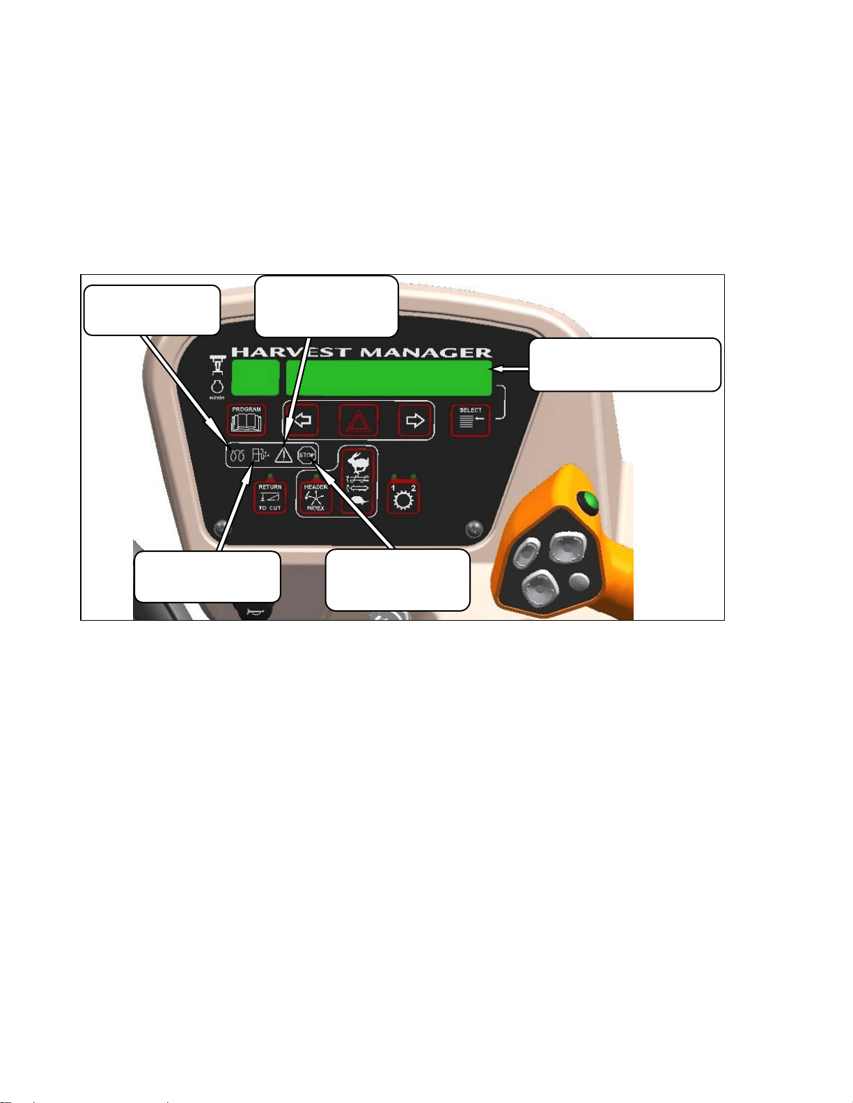
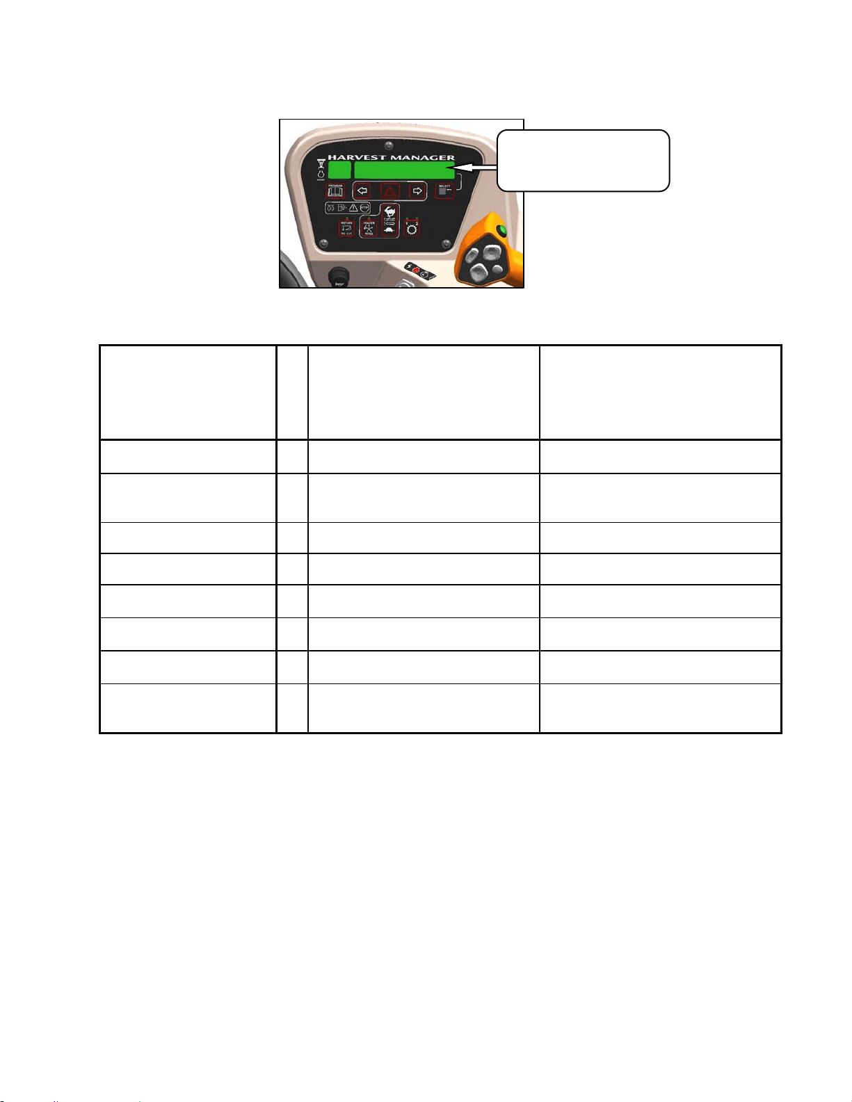
5.18.4 Cab Display Module (CDM)
Warnings/Alarms
The CDM displays warnings and sounds alarms
to notify the operator of abnormal windrower
status at startup when the ignition is turned on
and at engine operating speeds above 500 rpm.
5.18.4.1 Engine Warning Lights
WATER IN FUEL
Illuminates Yellow
Service Recommended
CAUTION
Illuminates Yellow
Do Not Operate Engine
Refer to Display Code
DISPLAY
Displays Malfunction Code
Refer to Technical Service Manual
ENGINE PREHEAT
Illuminates Yellow
Wait To Start Engine
STOP
Illuminates Red
Stop Engine Immediately
Refer to Display Code
OPERATOR’S STATION
169304 37 Rev. C
5.18.4.2 Display Warnings
DISPLAY WARNINGS AND ALARMS – ENGINE/TRANSMISSION
DISPLAY
FLASHING
ALARM TONE DESCRIPTION
ENGINE OIL PRESSURE
Continuous Loud Tone Until Oil
Pressure Is Regained.
Low Engine Oil Pressure.
Accompanied By Warning Lights.
ENGINE
TEMPERATURE
Ongoing Intermittent Moderate
Tone Until Temperature Is Below
215F. (102C.)
Engine Temperature Over 230F.
(110C.).
Accompanied By Warning Lights.
##.# LOW VOLTS
Single Loud Tone For 10 Seconds. Voltage Below 11.5.
##.# HIGH VOLTS
Single Loud Tone For 10 Seconds. Voltage Above 16.
IN PARK
One Short Beep
Steering Wheel Centered, And
Brakes Are Engaged.
PLACE GSL INTO “N”
Beeps At 2 Per Second Until
Corrected.
Interlock Switch Not Closed With
Key On/Engine Off.
TRANS OIL PRESS
Continuous Loud Tone Until Oil
Pressure Is Regained.
Low Transmission Charge Oil
Pressure.
TRANS OIL TEMP
Ongoing Intermittent Moderate
Tone Until Temperature Is Below
Acceptable Level.
Transmission Oil Temperature
Above 221F (105C).
DISPLAY WARNINGS
Informs Operator of Abnormal
Windrower Conditions
See Table Below

OPERATOR’S STATION
169304 38 Rev. C
DISPLAY WARNINGS AND ALARMS - WINDROWER
DISPLAY
FLASHING
ALARM TONE DESCRIPTION
BRAKE OFF
Engine Running, Brake Solenoid Not
Activated.
BRAKE SW FAILURE
Ignition On/Engine Not Running,
Brake Switch And Relay Closed.
CENTER STEERING
Beeps At 2 Per Second
Interlock Switch Not Closed With
Key On/Engine Off.
DISENGAGE HEADER
None
Header Switch Is In On Position
When Ignition Switch Turned On.
HEADER DISENGAGED
None Normal
HEADER OIL PRESS
Continuous Loud Tone Until Oil
Pressure Is Regained.
Low Header Charge Oil Pressure.
Header Shuts Down Automatically.
Header On Switch Must Be Moved
To Off Position And Then To On
Position To Restart The Header.
HYDRAULIC FILTER
Single Loud Tone For 10 Seconds.
Repeats Every 15 Minutes Until
Condition Is Corrected.
Excessive Pressure Drop Across
Hydraulic Oil Filter.
KNIFE OVERLOAD
Ongoing Intermittent Moderate
Tone Until Condition Is Corrected.
Machine Overload. Knife Speed
Drops Below Programmed Value.
LOW HYDRAULIC OIL
Continuous Loud Tone For 5
Seconds. If Condition Not
Rectified, Single Loud Tone Every
5 Minutes
Low Hydraulic Oil Level. Header
Shuts Down Automatically If
Engaged. Header On Switch Must
Be Moved To OFF Position And
Then To ON Position To Restart The
Header.
NO HEADER
None
Header Is Not Detected.
NO OPERATOR
Continuous Tone.
Operator Not Detected In Seat With
Header Engaged Or Out Of Neutral
Detent. Engine Shutdown After 5
Seconds
NOT IN PARK
Short Beep With Each Flash
Interlock Switch Not Closed With
Key On/Engine Off.
OPERATOR’S STATION
169304 39 Rev. C
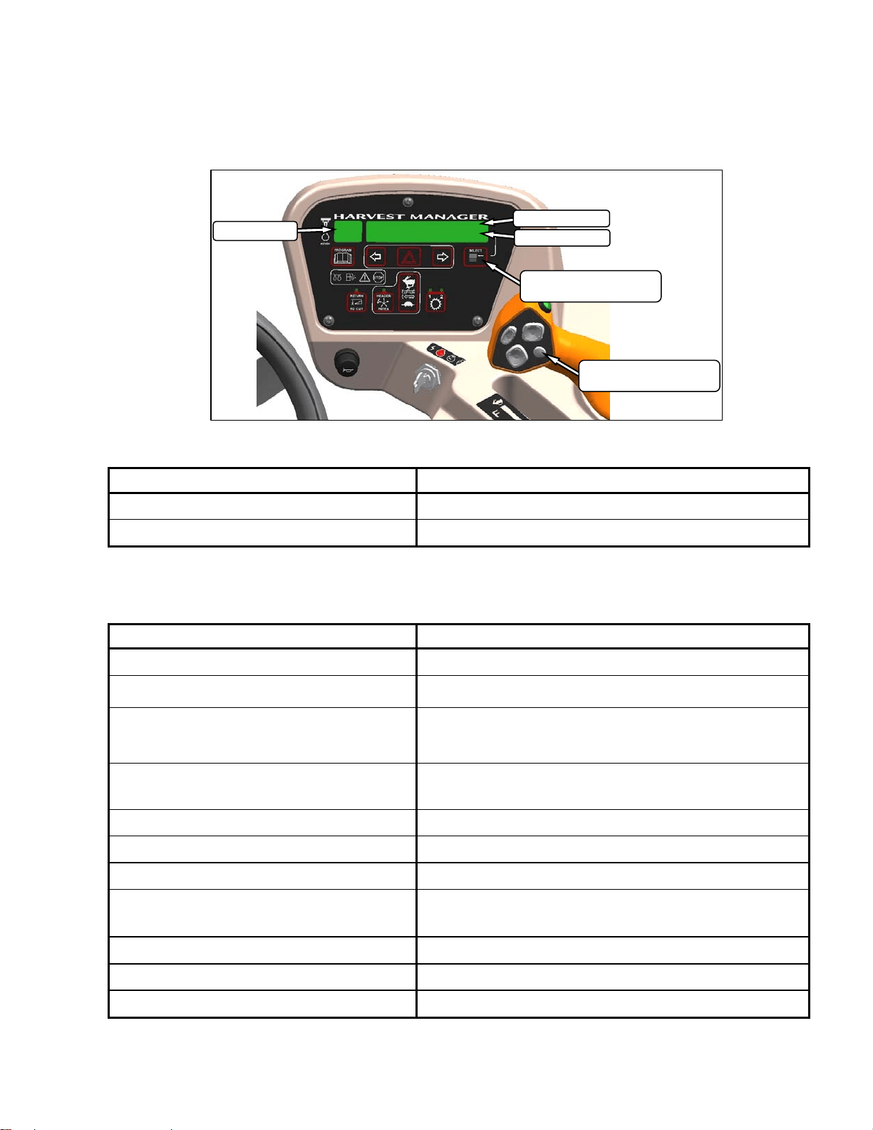
5.18.5 Cab Display Module (CDM)
Programming
The monitoring system requires programming
for each header and the header must be
attached to the windrower. Programming the
system may be accomplished with or without the
engine running. If the engine is running, the
transmission must be in neutral. If the engine is
not running, the ignition must be on. Exit
programming mode at any time by pressing the
PROGRAM switch or by turning off the ignition.
The system only needs to be programmed once
for each header. The operator may make
changes later on to a particular setting to suit
windrowing conditions or modifications to the
machine. Most functions have been pre-
programmed at the factory but can be changed
by the operator if required.
Proceed as follows to program the CDM:
IMPORTANT
Header must be attached to the
windrower. See paragraph 6.5, & 6.6.
a. Turn ignition key to RUN, or start the engine.
Refer to paragraph 6.3.5 Engine Operation.
b. Press PROGRAM and SELECT on CDM to
enter programming mode.
c. Press SELECT. TRACTOR SETUP? is
displayed on upper line.
d. Press and then SELECT.
e. HEADER TYPE? is displayed. DRAPER is
flashing on lower line.
f. Press or to change value on lower
line.
g. Press SELECT.
h. TILT CYL INSTALLED? is displayed.
i. Press or to change value on lower
line.
j. Press SELECT to advance to the next L1 item
and press arrow keys to change values.
k. Press PROGRAM to exit programming mode
when finished entering desired values.
Refer to Detailed Programming Instructions on
following pages.
NOTE
Contact your dealer for information
regarding software updates to the
electronic modules. Your dealer will have
the necessary interface tools and access
to the latest software upgrades.
* Fast scroll applies only when changing OVERLOAD PRESSURE, and TIRE SIZE.
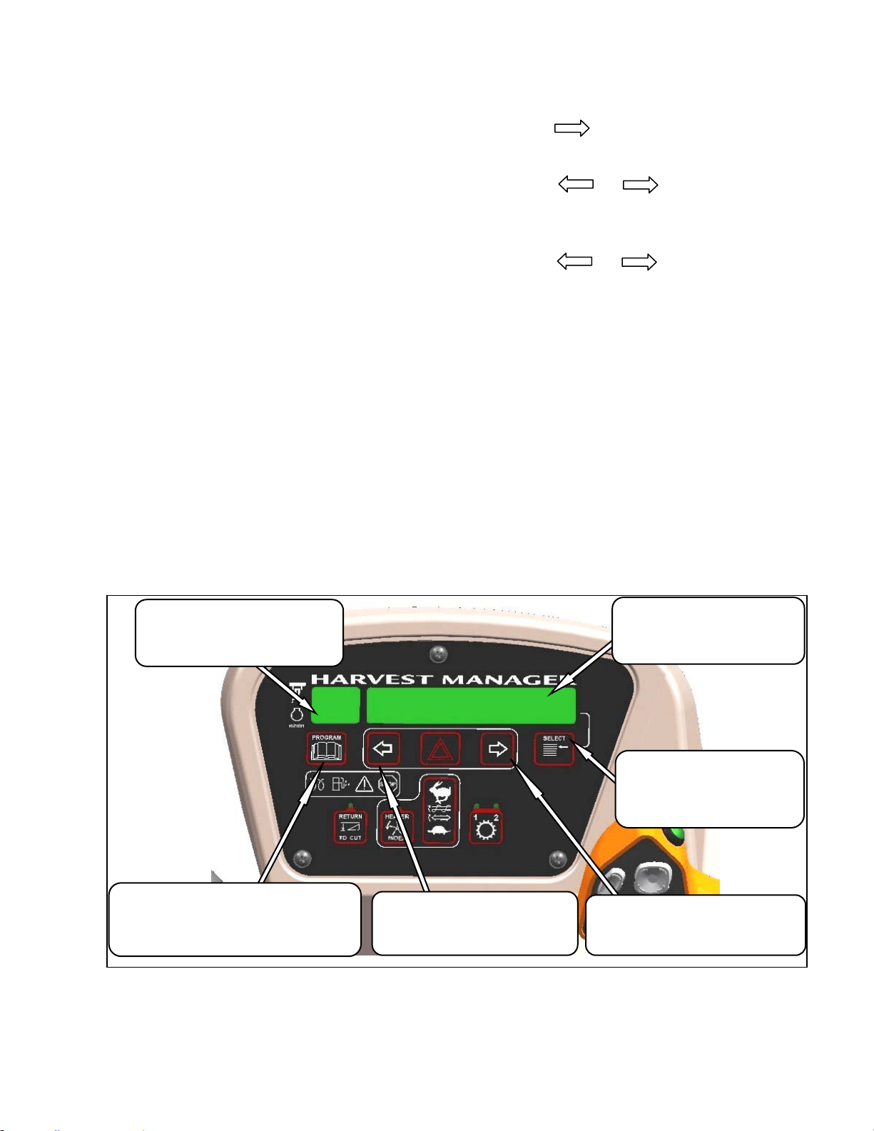
MENU ITEM SCROLL BACKWARD
Displays Value Under Menu Item
Push To Scroll Backward.
Keep Depressed For Fast Scroll. *
MENU ITEM SCROLL FORWARD
Displays Value Under Menu Item
Push To Scroll Forward.
Keep Depressed For Fast Scroll. *
MAIN DISPLAY
Displays Menu Item and Selection
Upper Line – Menu Item
Lower Line - Selection
SELECT SWITCH
Places Monitor Into Program
Mode With PROGRAM SWITCH
Press to Accept Menu Item and
Advance to Next Item.
SIDE DISPLAY
Displays Software Revision Status
Upper Line – C### (CDM)
Lower Line – M### or T### (WCM)
PROGRAM SWITCH
Places Monitor Into Program Mode
Press While Depressing SELECT Switch
Press To Exit Program Mode.
OPERATOR’S STATION
169304 40 Rev. C
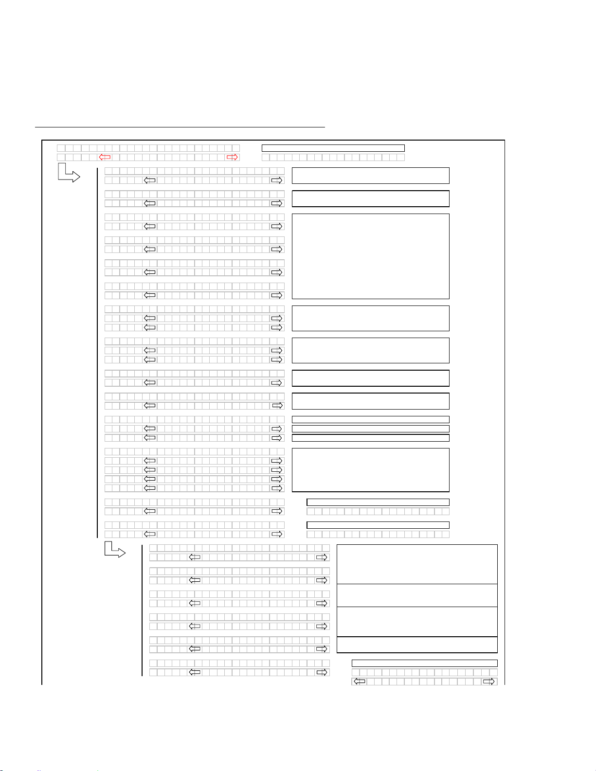
DETAILED PROGRAMMING INSTRUCTIONS
(Key On / Engine Running or Not / Header Disengaged).
(Press PROGRAM and SELECT on CDM to enter programming mode).
NOTE: ENGINE MUST BE RUNNING TO CALIBRATE SENSORS
.
(continued next page)
L1 Cxxx
||
TR
A
CTOR SETUP?
L2Mxxx
||
NO /
Y
ES C
A
BDISPL
A
Y
SETUP?
L1 C x x x
||
SELECT HE
A
DER T
Y
PE?
L2 M x x x
||
DR
A
PER
L1 C x x x
||
SELECT HE
A
DER T
Y
PE?
L2 M x x x
||
A
30
A
UGER
L1 C x x x
||
SELECT HE
A
DER T
Y
PE?
L2 M x x x
||
A
40
A
UGER
L1 C x x x
||
TILT C
Y
L INST
A
LLED?
L2 M x x x
||
NO /
Y
ES
L1 C x x x
||
REEL FORE /
A
FT?
L2 M x x x
||
NO /
Y
ES
L1 C x x x
||
KN I F E O
V
ERLO
A
DSPD?
L2 M x x x
||
1000 SPM
L1 C x x x
||
HE
A
DER I NDEX MODE?
L2 M x x x
||
REEL & CON
V
E
Y
OR
L2 M x x x
||
REEL ONL
Y
L1 C x x x
||
RE TURN TO CUT MODE?
L2 M x x x
||
HEIGHT & TILT
L2 M x x x
||
HEIGHT ONL
Y
L1 C x x x
||
HE
A
DER CUT WI DTH?
L2 M x x x
||
20.5 FEET
L1 C x x x
||
H
A
Y
COND I T I ONER ?
L2 M x x x
||
NO /
Y
ES
L1 C x x x
||
A
UGER HDR REE L S PD
L2 M x x x
||
RPM / MPH
L2 M x x x
||
RPM / KPH
L1 C x x x
||
SET T I RE S I ZE?
L2 M x x x
||
18.4X26 TURF
L2 M x x x
||
18.4X26 B
A
R
L2 M x x x
||
23.1X26 TURF
L2 M x x x
||
600 - 65 R28
L1 C x x x
||
SET ENGI NE I SC RPM?
L2 M x x x
||
OFF / ON SET CONTROL LOCKS?
L1 C x x x
||
SET CONTROL LOCKS?
L2 M x x x
||
NO /
Y
ES
V
IEW CONTROL LOCKS?
L1 Cxxx
||
DR
A
PER SPEED
L2 Mxxx
||
EN
A
BLED / LOCKED
L1 Cxxx
||
A
UGER SPEED
L2 Mxxx
||
EN
A
BLED / LOCKED
L1 Cxxx
||
REEL SPEED
L2 Mxxx
||
EN
A
BLED / LOCKED
L1 Cxxx
||
REEL FORE /
A
FT
L2 Mxxx
||
EN
A
BLED / LOCKED
L1 Cxxx
||
HE
A
DER T I LT
L2 Mxxx
||
EN
A
BLED / LOCKED
L1 Cxxx
||
EX I T CONTROL LOCKS?
L2 Mxxx
||
NO /
Y
ES DR
A
PER SPEED
EN
A
B L E D / L O C K E D
Programming Menu Flow Chart
If "NO" then jump to:
Use the "arrow" keys to set the header cut width.
If the REEL SPEED sensor is not "installed" (A30
Auger Header selected) in the TRACTOR SETUP
menu, the INDEX mode should be suppressed.
If the HEADER TILT sensor is not "installed" (no
expansion module installed), then the RTC mode
should default to HEIGHT only.
Selects the header type, the selected header will be
flashing. The "factory" default to be DRAPER.
If the A30 is selected then the reel speed should be
suppressed as there is no reel speed sensor.
AUGER HEADER ONLY
For IMPERIAL displa
y
.
For METRIC display.
If a DRAPER or A40 is selected the reel speed
should be enabled (with expansion module installed).
Knife Overload Speed should be suppressed unless
the expansion module is installed.
The TILT selection needs to be available even if the
expansion module is not installed.
DRAPER HEADER ONLY. Default will be flashing.
Use "arrow" keys to select.
If "NO" then jump to:
Pressing "SELECT" will jump to:
This menu allows the operator to selectably "lock out"
the control functions for the various header functions.
The default or selected "status" for each item will
flash.
If the expansion module is not installed the
corresponding menu items should be suppressed.
The "arrow" keys are used to ENABLE or LOCK OUT
each function. Pressing "SELECT" will go to the next
L1 menu item.
Pressing "SELECT" will go to the next line 1 (L1)
menu selection. The turn signal "arrow" keys are
used to change the values.
If "NO" then jump to:
Tilt to be suppressed if not "installed" in the tractor
setup menu.
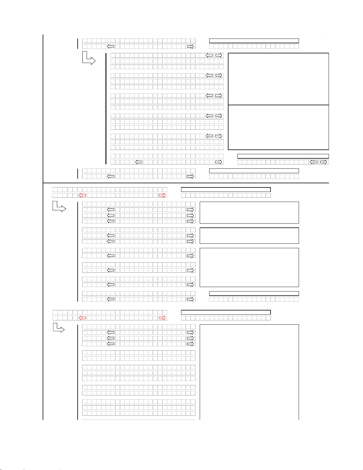
OPERATOR’S STATION
169304 41 Rev. C
(continued next page)
L1 Cxxx
||
V
IEW CONTROL LOCKS?
L2 Mxxx
||
NO /
Y
ES E
X
IT TR
A
CTOR SETUP?
L1 Cxxx
||
DR
A
PER SPEED
L2 Mxxx
||
575. 1 HRS EN
A
BLED
L2 Mxxx
||
648. 6 HRS LOCKED
L1 Cxxx
||
A
UGER SPEED
L2 Mxxx
||
575. 1 HRS EN
A
BLED
L2 Mxxx
||
648. 6 HRS LOCKED
L1 Cxxx
||
REEL SPEED
L2 Mxxx
||
575. 1 HRS EN
A
BLED
L2 Mxxx
||
648. 6 HRS LOCKED
L1 Cxxx
||
REEL FORE /
A
FT
L2 Mxxx
||
575. 1 HRS EN
A
BLED
L2 Mxxx
||
648. 6 HRS LOCKED
L1 Cxxx
||
HE
A
DER T I LT
L2 Mxxx
||
575. 1 HRS EN
A
BLED
L2 Mxxx
||
648. 6 HRS LOCKED
L1 Cxxx
||
E
X
IT
V
IEW LOCKOUTS?
L2 Mxxx
||
NO/
Y
ES DR
A
PER SPEED
L1 Cxxx
||
E
X
IT TR
A
CTOR SETUP?
L2 Mxxx
||
NO /
Y
ES T I LT C
Y
LINST
A
LLED?
L1 C x x x
||
C
A
B DISPL
A
Y
SETUP?
L2 M x x x
||
NO /
Y
ES C
A
LIBR
A
TE SENSORS?
L1 Cxxx
||
DISPL
A
Y
L
A
NGU
A
GE?
L2 Mxxx
||
ENGLISH
L2 Mxxx
||
ESP
A
NOL
L2 Mxxx
||
RUSSI
A
N
L1 Cxxx
||
DISPL
A
Y
UN I TS?
L2 Mxxx
||
IMPERI
A
L
L2 Mxxx
||
METRIC
L1 Cxxx
||
CDM BUZ ZER
V
OLUME
L2 Mxxx
||
▂
▂
▃
▅
▆
▇
L1 Cxxx
||
CDM B
A
CKL I GHT I NG
L2 Mxxx
||
▂
▂
▃
▅
▆
▇
L1 Cxxx
||
CDM CONTR
A
ST
L2 Mxxx
||
▂
▂
▃
▅
▆
▇
L1 Cxxx
||
E
X
IT DISPL
A
Y
SETUP?
L2 Mxxx
||
NO /
Y
ES D I SPL
A
Y
L
A
NGU
A
GE?
L1 C x x x
||
C
A
LIBR
A
TE SENSORS?
L2 M x x x
||
NO /
Y
ES D I
A
GNOS T I C MODE ?
L1 Cxxx
||
TO C
A
LIBR
A
TE SELECT
L2 Mxxx
||
HE
A
DER HE I GHT
L2 Mxxx
||
HE
A
DER T I LT
L2 Mxxx
||
STOP & E
X
IT
L1 Cxxx
||
HE I GHT SENSOR C
A
L
L2 Mxxx
||
R
A
I SE HDR TO ST
A
RT
L1 Cxxx
||
C
A
LIBR
A
TING HEIGHT
L2 Mxxx
||
R
A
ISE HE
A
DER HOLD
L2 Mxxx
||
R
A
ISE HE
A
DER DONE
L1 Cxxx
||
HE I GHT SENSOR C
A
L
L2 Mxxx
||
PRESS LOWER HE
A
DER
L1 Mxxx
||
C
A
LIBR
A
TING HEIGHT
L2 Mxxx
||
LOWER HE
A
DER HOLD
L2 Mxxx
||
HT SENSOR COMPLETE
When the control lock outs are viewed, the lower
display line (L2) will show the engine hours and either
ENABLED or LOCKED to indicate the present status
along with the engine hours at which time the function
was either ENABLED or LOCKED.
If any of the HDR ANGLE / KNIFE SPEED or REEL
SPEED sensors are not "installed" (no expansion
module or A30 Auger header selected, they should be
suppressed.
The operator can select any of the two items
requiring calibration or to STOP & EXIT the menu.
If "NO" then jump to:
The "arrow" keys are used to select between
IMPERIAL or METRIC. The default value will be
displayed first.
If "NO" then jump to:
Using the "arrow" keys allows the operator to select
the various functions. Pressing "SELECT" will go to
the EXIT VIEW LOCKOUTS? menu selection.
If "NO" then jump to:
The "arrow" keys are used to change the CDM
buzzer volume, CDM backlighting or the CDM
contrast, with the bar graph indicating the relative
level for each item. When "SELECT" is pressed the
program goes to the EXIT DISPLAY SETUP? menu
selection.
When a function is activated, the display will indicate
the function being calibrated. HOLD will flash until
the system has completed reading in the signal with
the header fully raised.
If "NO" then jump to:
If "NO" then
j
ump to:
Use the "arrow" keys to change the default language.
Pressing "SELECT" goes to the next L1 menu
selection.
If "NO" then jump to:
DONE will flash and prompt the operator to
COMPLETE the sensor calibration by lowering the
header.
OPERATOR’S STATION
169304 42 Rev. C
(continued next page)
L1 C x x x
||
TO C
A
LIBR
A
TE SELECT
L2 M x x x
||
HE
A
DER HE I GHT
L1 C x x x
||
TO C
A
LIBR
A
TE SELECT
L2 M x x x
||
HE
A
DER HE I GHT
L2 M x x x
||
HE
A
DER T I LT
L1 M x x x
||
HDR T I L T SENSOR C
A
L
L2 M x x x
||
EXTEND TLT TO ST
A
RT
L1 C x x x
||
C
A
LIBR
A
TING TILT
L2 M x x x
||
EXTEND T I LT HOLD
L2 M x x x
||
EXTEND T I LT DONE
L1 M x x x
||
HDR T I L T SENSOR C
A
L
L2 M x x x
||
PRESS RETR
A
CT T I LT
L1 C x x x
||
C
A
LIBR
A
TING TILT
L2 M x x x
||
RETR
A
CT T I LT HOLD
L2 M x x x
||
HDR T I L T COMPLETE
L1 C x x x
||
TO C
A
LIBR
A
TE SELECT
L2 M x x x
||
HE
A
DER T I LT
L2 M x x x
||
STOP & EX I T
L1 C x x x
||
EX I T C
A
LIBR
A
TION?
L2 M x x x
||
NO /
Y
ES TO C
A
LIBR
A
TE SELECT
L1 C x x x
||
DI
A
GNOS T I C MODE ?
L2 M x x x
||
NO /
Y
ES TR
A
CTOR SETUP?
L1 C x x x
||
V
I EW ERROR CODES?
L2 M x x x
||
NO /
Y
ES ENTER SENSOR SETUP?
L1 C x x x
||
V
IEW TR
A
CTOR CODES?
L2 M x x x
||
NO/
Y
ES ENTER SENSOR SE TUP ?
L1 1
||
1234 . 5 HRS 123
L2 E 4 7
||
SENSOR
V
OLTS LOW
L1 2
||
1234 . 5 HRS 123
L2 E 7 1
||
LOW H
Y
DR
A
UL I C O I L
L1 C x x x
||
EX I T TR
A
CTOR CODES?
L2 M x x x
||
NO/
Y
ES
V
IEW TR
A
CTOR CODES ?
L1 C x x x
||
ENTER SENSOR SETUP?
L2 M x x x
||
NO /
Y
ES RE
A
DSENSOR INPUTS?
L1 C x x x
||
HE
A
DER HT SENSOR
L2 M x x x
||
EN
A
BLE / D I S
A
BLE
L1 C x x x
||
HE
A
DER T I LT SENSOR
L2 M x x x
||
EN
A
BLE / D I S
A
BLE
L1 C x x x
||
K
N I FE SPEED SENSOR
L2 M x x x
||
EN
A
BLE / D I S
A
BLE
L1 C x x x
||
REEL SPEED SENSOR
L2 M x x x
||
EN
A
BLE / D I S
A
BLE
L1 C x x x
||
EX I T SENSOR SETUP?
L2 M x x x
||
NO/
Y
ES
K
N I FE SPEED SENSOR
The operator can select each sensor and selectively
enable or disable the sensor in the event of a sensor
malfunction.
The last 10 distinct error codes are stored along with
the code #, Exxx, engine hours and number of
occurrences. The "arrow" keys are used to cycle
between codes.
If the HEADER TILT option in the TRACTOR SETUP
is set to NO then only HEIGHT should be available
as a menu selection for calibration.
If "NO" then jump to:
If "NO" then jump to:
If "NO" then jump to:
If "NO" then jump to:
The menu will display the last item selected when the
calibration routine is completed.
If no expansion module or an A30 auger header is
selected, the corresponding menu items should be
suppressed.
Or to the first sensor "installed"
If "NO" then jump to:
If "NO" then jump to:
If "NO" then jump to:
When "SELECT" is pressed the program goes to the
EXIT SENSOR SETUP? selection.
OPERATOR’S STATION
169304 43 Rev. C
L1 C x x x
||
RE
A
D SENSOR INPUTS?
L2 M x x x
||
N O /
Y
ES
A
CT I
V
A
TE FUNCT I ONS?
L1 C x x x
||
SENSOR I NPUT
L2 M x x x
||
HDR HE I GHT 3 . 5 9
V
L1 C x x x
||
SENSOR I NPUT
L2 M x x x
||
HE
A
DER
A
NGL E 1 . 8 4
V
L1 C x x x
||
SENSOR I NPUT
L2 M x x x
||
KN I F E SPEED 1 2 3 HZ
L1 C x x x
||
SENSOR I NPUT
L2 M x x x
||
REEL SPEED 123 HZ
L1 C x x x
||
SENSOR I NPUT
L2 M x x x
||
WH E E L S P E E D 1 2 3 H Z
L1 C x x x
||
E
X
IT RE
A
DSENSORS?
L2 M x x x
||
NO /
Y
ES SENSOR I NPUT
HDR HE I GHT 3 . 5 9
V
L1 C x x x
||
SENSOR I NPUT
L2 M x x x
||
HDR HE I GHT SENSOR
L1 C x x x
||
SENSOR I NPUT
L2 M x x x
||
HE
A
DER
A
NGL E S ENSOR
L1 C x x x
||
SENSOR I NPUT
L2 M x x x
||
KN I FE SPEED SENSOR
L1 C x x x
||
SENSOR I NPUT
L2 M x x x
||
REEL SPEED SENSOR
L1 C x x x
||
A
CT I
V
A
TE FUNCT I ONS?
L2 M x x x
||
N O /
Y
ES E
X
IT DI
A
GNOST I CS ?
L1 C x x x
||
A
CT I
V
A
TE FUNCT I ONS?
L2 M x x x
||
HE
A
DER DOWN / UP
L1 C x x x
||
A
CT I
V
A
TE FUNCT I ONS?
L2 M x x x
||
REEL DOWN / UP
L1 C x x x
||
A
CT I
V
A
TE FUNCT I ONS?
L2 M x x x
||
HDR T I L T I N / OUT
L1 C x x x
||
A
CT I
V
A
TE FUNCT I ONS?
L2 M x x x
||
KN I F E DR I
V
EON
L1 C x x x
||
A
CT I
V
A
TE FUNCT I ONS?
L2 M x x x
||
DR
A
PER /
A
UGER ON
L1 C x x x
||
A
CT I
V
A
TE FUNCT I ONS?
L2 M x x x
||
REEL FORE /
A
FT
L1 C x x x
||
A
CT I
V
A
TE H
Y
DPURGE?
L2 M x x x
||
NO /
Y
ES
L1 C x x x
||
TO
A
CT I
V
A
TE PURGE
L2 M x x x
||
PRESS
A
ND HOLD
L1 C x x x
||
PURGE C
Y
CLE ST
A
RTED
L2 M x x x
||
PRESS
A
ND HOLD
L1 C x x x
||
PURGE C
Y
CLE ENDED
L2 M x x x
||
L1 C x x x
||
PURGE C
Y
CLE ENDED
L2 M x x x
||
NO E
X
IT
Y
ES
L1 C x x x
||
E
X
IT FUNCTION MENU?
L2 M x x x
||
NO /
Y
ES HE
A
DER DOWN / UP
L1 C x x x
||
E
X
IT DI
A
GNOST I CS ?
L2 M x x x
||
NO /
Y
ES D I
A
GNOST I C MOD E ?
If "NO" then jump to:
If "NO" then jump to:
ACTIVATE HYD PURGE - This is to allow the
operator to purge the air from a new or changed pump
system.
Pressing and holding the right hand "arrow" button
activates a predetermined timed purge cycle.
Releasing pressure on the switch or a completed
cycle (timed out) will jump to the PURGE CYCLE
ENDED menu selection.
If the HEADER TILT cylinder or the REEL FORE /
AFT valve is not installed under the TRACTOR
SETUP menu then the ACTIVATE FUNCTIONS menu
selection for these items should be suppressed.
If no expansion module or an A30 auger header is
selected, the corresponding menu items should be
suppressed.
For diagnostic purposes each header function can be
activated by using the "arrow" keys on the CDM.
When "SELECT" is pressed the program will go to the
next function that can be activated.
If "NO" then jump to:
If a sensor has been disabled "SENSOR" will be
flashing in the area where the input reading would
have been.
When "SELECT" is pressed the program goes to the
EXIT READ SENSORS? menu selection.
For diagnostic purposes each sensors input signal can
be read.
If no expansion module or an A30 auger header is
selected, the corresponding menu items should be
suppressed.
If "NO" then jump to:
Adds a selection to be able to read in the wheel speed
frequency.
If "NO" then jump to:

OPERATOR’S STATION
169304 44 Rev. C
5.18.6 Engine Error Codes
The CDM displays “Error Codes” when there is a fault with one of the several sensors that monitor and control
engine operation, to assist the operator or technician in locating a specific problem with engine operation.
Refer to the Appendix for the “Error Codes”.
5.18.7 CDM & WCM Fault Codes
The CDM displays “Fault Codes” when there is a fault with one of the several sensors that monitor and control
windrower operation, to assist the operator or technician in locating a specific problem with the windrower.
Refer to the Appendix for the “Fault Codes”.
OPERATOR’S STATION
169304 45 Rev. C
6 OPERATION
6.1 OWNER/OPERATOR
RESPONSIBILITIES
CAUTION
• It is your responsibility to read and
understand this manual completely
before operating the windrower. Contact
your dealer if an instruction is not clear
to you.
• Follow all safety messages in the manual
and on safety signs on the machine.
• Remember that YOU are the key to
safety. Good safety practices protect you
and the people around you.
• Before allowing anyone to operate the
windrower, for however short a time or
distance, make sure they have been
instructed in its safe and proper use.
• Review the manual and all safety related
items with all operators annually.
• Be alert for other operators not using
recommended procedures or not
following safety precautions. Correct
these mistakes immediately, before an
accident occurs.
• Do not modify the machine. Unauthorized
modifications may impair the function
and/or safety and affect machine life.
• The safety information given in this
manual does not replace safety codes,
insurance needs, or laws governing your
area. Be sure your machine meets the
standards set by these regulations.
6.2 SYMBOL DEFINITIONS
The following symbols are used to depict
functions or reactions at the various instruments
and controls. Learn the meaning of these
symbols before operating the Windrower.
6.2.1 Engine Functions
Electrical
Power-
Accessories
Engine Stop
Engine Coolant
Temperature
Engine
Throttle
Engine Glow
Plugs
Engine
Urgent Stop
Engine
Malfunction
Fast
Engine Rpm
Slow
Engine Run
Water In
Fuel
Engine Start
6.2.2 Windrower Operating Symbols
Turn Signals
Windshield
Wiper
Hazard
Warning Lights
Seat Height
Up
Forward
Seat Height
Down
Neutral
Seat Fore
And Aft
Reverse
Beacon
Headlights Low
Beam/Road
Lights
Seat Back
Fore And Aft
Headlights High
Beam/Road
Lights
Work Light
Cab
Temperature
Control
Lighter
OPERATOR’S STATION
169304 46 Rev. C
Windrower Operating Symbols
(cont’d)
Air Conditioning
Fresh Air
Blower
6.2.3 Header Functions
Program
Header Tilt
Up
Header Index
Header
Down
Return To Cut
Header Up
Conveyor
Speed
Header Tilt
Down
Increase
Decrease
Reel Speed
Deck Shift
Reel Down
Header
Engage
Reel Forward
Header
Disengage
Reel Up
Push Down
Header
Disengage
Reel Rearward
Pull Up
Header
Engage
Display Select
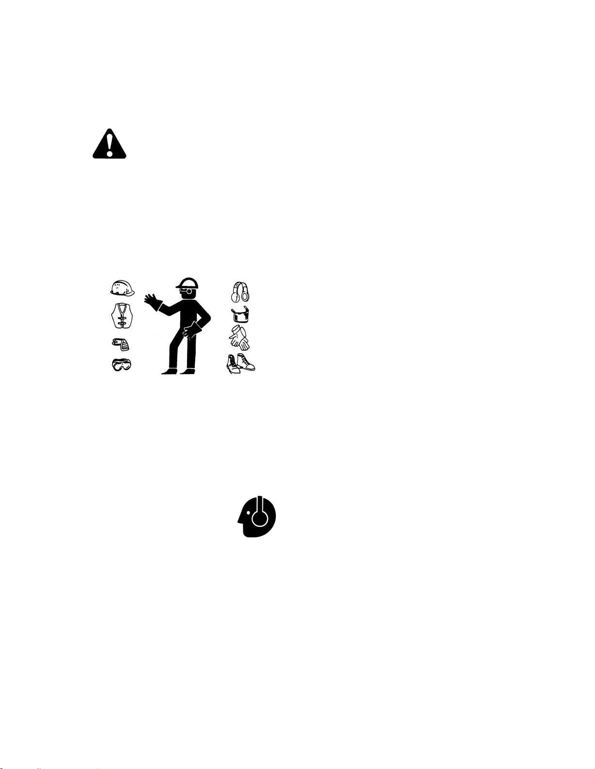
WINDROWER OPERATION
169304 47 Rev. C
6.3 WINDROWER OPERATION
6.3.1 Operational Safety
Follow these safety precautions:
CAUTION
• Wear close fitting clothing and protective
shoes with slip resistant soles.
• Remove foreign objects from the
machine and surrounding area.
• Carry with you any protective clothing
and personal safety devices that COULD
be necessary through the day. Don't take
chances.
• You may need:
- a hard hat
- protective glasses or goggles
- heavy gloves
- respirator or filter mask
- wet weather gear
• Protect against noise.
Wear a suitable hearing
protective device such
as ear muffs or ear plugs
to protect against
objectionable or uncomfortable loud noises.
• Follow all safety and operational
instructions given in your Operator's
Manuals. If you do not have a windrower
and/or combine manual, get one from
your dealer and read it thoroughly.
• Never attempt to start the engine or
operate the machine except from the
operator’s seat.
• Check the operation of all controls in a
safe clear area before starting work.
• Stop engine and remove key before
adjusting or removing plugged material
from the machine. A child or even a pet
could engage the drive.
• Check for excessive vibration and
unusual noises. If there is any indication
of trouble, shut down and inspect the
machine. Follow proper shutdown
procedure. Refer to Section 6.3.5.3
Shutdown Procedure.
• Operate only in daylight or good artificial
light.
6.3.2 Break-In Period
The windrower is ready for normal operation.
However there are several items to check and
watch out for during the first 150 hours.
6.3.2.1 Engine
a. Operate engine at moderate load and avoid
extremely heavy or light loading for longer than
5 minutes.
b. Avoid unnecessary idling. If engine will be idling
for longer than 5 minutes after reaching
operating temperature, turn key OFF to stop
engine.
c. Check engine oil level frequently. Watch for any
signs of leakage. If oil must be added, refer to
Section 7.8.2 Oil Level.
NOTE
During the break-in period, a higher than
usual oil consumption should be
considered normal.
NOTE
If windrower must be driven in cold
weather (below freezing), let engine idle
for 3 minutes, and then operate at
moderate speed until oil has warmed up.
d. Watch for temperature rising beyond normal
operating range. Check that coolant level at
reserve tank (mounted next to radiator) stays
between HOT and COLD marks on tank. Refer
to Section 7.8.7.1 Cooling System. If over-
heating problems occur, check for coolant leaks.

OPERATOR’S STATION
169304 48 Rev. C
6.3.2.2 Windrower
IMPORTANT
Until you become familiar with the sound
and feel of your new windrower, be extra
alert and attentive.
DANGER
Before investigating an unusual sound or
attempting to correct a problem, place GSL
in N-DETENT, shut off engine, and remove
key.
Perform the checks and service specified in
Section 7.13.1 Break-In Inspection.
6.3.3 Pre-Season Check
a. Perform the following safety checks at the
beginning of each operating season:
CAUTION
• Review the Operator's Manual to refresh
your memory on safety and operating
recommendations.
• Review all safety signs and other decals
on the windrower and note hazard areas.
• Be sure all shields and guards are
properly installed and secured. Never
alter or remove safety equipment.
• Be sure you understand and have
practiced safe use of all controls. Know
the capacity and operating
characteristics of the machine.
• Store a properly stocked first aid kit and
charged fire extinguisher on the
windrower.
b. Perform the following checks:
1. Drain off excess hydraulic oil added for
storage. Refer to Section 7.11.2 Changing
Hydraulic Oil.
2. Remove plastic bags and/or tape from all
sealed openings (air cleaner intake, exhaust
pipe, fuel tank).
3. Charge battery and install. Be sure terminals
are clean and cables are connected
securely.
4. Adjust tension on A/C compressor belt. See
Section 7.8.8.3 Tension.
5. Cycle A/C switch to distribute A/C refrigerant
oil.
c. Perform annual maintenance. See Section 7.13
Maintenance Schedule.
6.3.4 Daily Check
a. Check the machine for leaks or any parts that
are missing, broken, or not working correctly.
NOTE:
Use proper procedure when searching for
pressurized fluid leaks. Refer to Section
7.11.7 Hoses and Lines.
b. Clean the windows and mirrors to be sure of
good visibility in all directions. Stand on the
platform to access the rear window. Hold onto
the hand-holds on the cab front corners and
stand on the header anti-slip strips to wash the
front window.
c. Clean all lights and reflective surfaces to
maintain visibility to others.
d. Perform Daily maintenance. Refer to Section
7.13.2 Interval Maintenance.
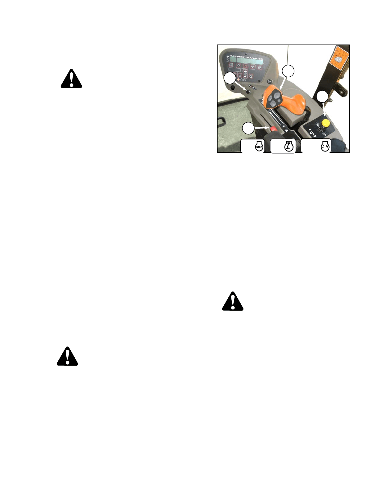
WINDROWER OPERATION
169304 49 Rev. C
6.3.5 Engine Operation
6.3.5.1 Starting
DANGER
• Avoid possible injury or death from a
runaway machine.
• Do not start engine by shorting across
starter terminals. Machine will start in
gear and move if normal starting circuitry
is bypassed.
• This machine has safety devices which
prevent the engine from starting. The
ground speed lever is in N-DETENT, the
steering wheel is locked in the neutral
position, and the header drive switch is
in the OFF position. Under no
circumstances are these circuits to be
deliberately rewired or misadjusted so
that the engine can be started with
controls out of neutral.
• Never start engine by shorting across
starter terminals. Machine will start with
drive engaged and move if normal
starting circuitry is bypassed.
• Never try to start engine with someone
under or near machine.
• Start engine only from operator's seat
with controls in neutral. NEVER start
engine while standing on ground.
Machine will start in gear and move if
normal starting circuitry is bypassed.
• Before starting engine, be sure there is
plenty of ventilation to avoid
asphyxiation.
IMPORTANT
Do not tow machine to start engine.
Damage to hydrostatic drives will result.
WARNING
Before starting engine, securely fasten your
seat belt and ensure trainer’s seat belt is
fastened if occupied. The seat belt can help
insure your safety if it is used and
maintained.
a. Move GSL (A) into N-DETENT.
b. Turn steering wheel until it locks.
c. Fasten seat belt.
d. Push header drive switch (B) to off.
e. Normal Start - engine temperature above 60°F
(16°C):
1. Set throttle (C) to start position – fully back.
IMPORTANT
The machine gauges and instruments
provide important information about
machine operation and condition.
Familiarize yourself with the gauges and
monitor them carefully during start-up
operation. Refer to Section 5.15, Engine
Controls/Gauges.
2. Turn ignition key (D) to RUN position.
CAUTION
Be sure the area is clear of other persons,
pets etc. before proceeding.
3. Single loud tone sounds, engine warning
lights illuminate and CDM displays HDR
DISENGAGED or HEADER ENGAGED and
IN PARK.
4. Turn ignition key to START position until
engine starts and then release key. Tone
ceases and warning lights go out. CDM
displays programmed header data for 5
seconds if attached and then returns to
previous display.
(continued next page)
D
A
B
C
START
RUN
OFF
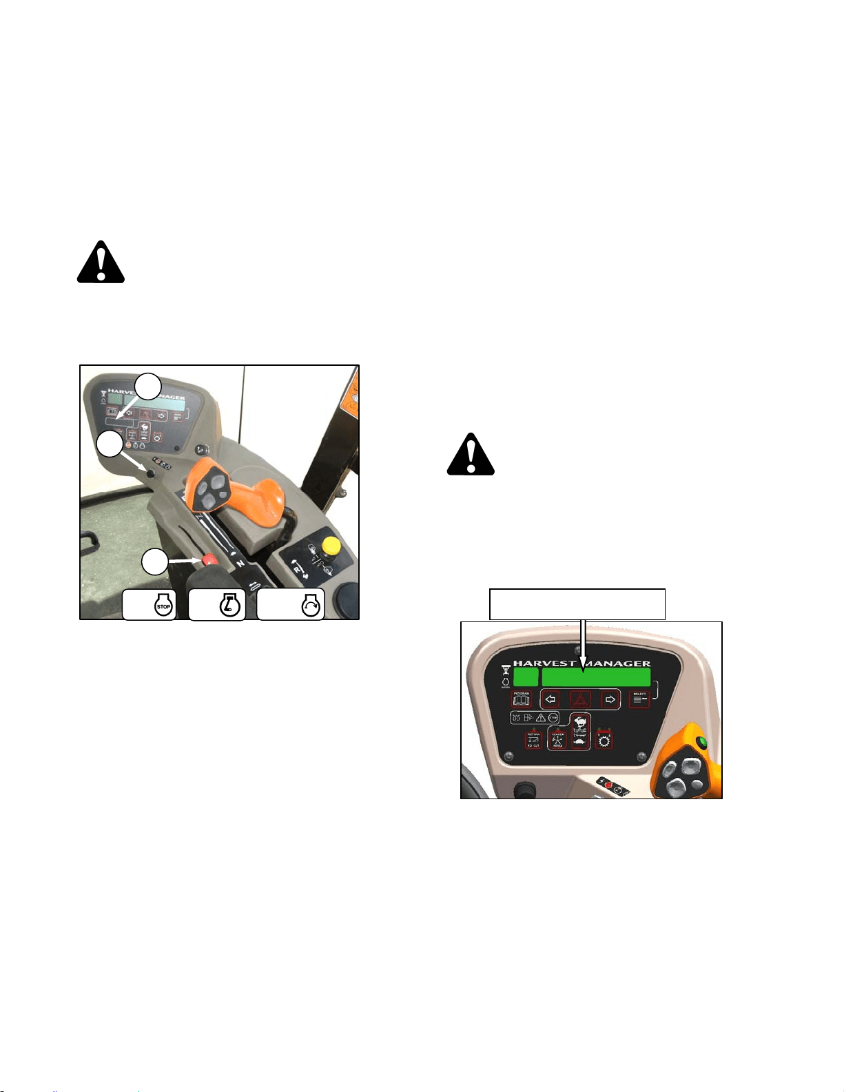
OPERATOR’S STATION
169304 50 Rev. C
IMPORTANT
Do not operate starter for longer than 15
seconds at a time. If engine does not start,
wait at least two minutes before trying
again. After the third 15 second crank
attempt, allow solenoid to cool for 10
minutes before further cranking attempts.
If engine still does not start, refer to
Trouble Shooting section.
WARNING
If starter engages with steering wheel
unlocked, ground speed lever out of neutral,
or header clutch engaged, DO NOT START
ENGINE. See your dealer.
f. Cold Start - engine temperature below 40°F
(5°C).
1. Set throttle (C) to start position – fully back
(low idle).
2. Turn key (D) to RUN.
3. Grid heater light (E) on CDM will cycle
on/off/on after 2 seconds for a pre-set length
of time. The operating period for the glow
plug light will change depending engine
temperature.
4. When grid heater light goes out, turn key to
START and crank engine until it starts.
Leave throttle at IDLE.
5. If engine fails to start, repeat steps 1 to 4.
6. Engine will cycle through a period where it
appears to labour.
NOTE
Throttle is non-responsive during this time
as engine is in “WARM UP” mode. This
mode will last from 30 seconds to 3
minutes depending on temperature. After
engine has stabilized and idling normally,
throttle becomes active.
IMPORTANT
Do not operate engine above 1500 rpm
until engine temperature gauge is above
100°F (40˚C).
IMPORTANT
Do not operate starter for longer than 15
seconds at a time. If engine does not start,
wait at least two minutes before trying
again. After the third 15 second crank
attempt, allow solenoid to cool for 10
minutes before further cranking attempts.
If engine still does not start, refer to
Section 8 Trouble Shooting.
WARNING
If starter engages with steering wheel
unlocked, ground speed lever out of neutral,
or header clutch engaged, DO NOT START
ENGINE. See your windrower dealer.
6.3.5.2 Engine Warm-Up
Allow engine to run with throttle lever (C) at or
near low idle position until temperature reaches
approximately 100°F (40°C).
ENGINE TEMP 100 ° F
D
E
C
START
RUN
OFF
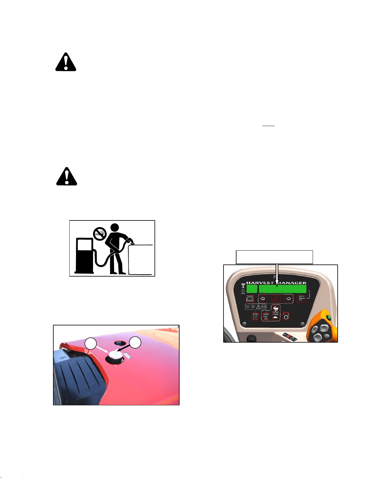
WINDROWER OPERATION
169304 51 Rev. C
6.3.5.3 Shutdown
CAUTION
Be sure windrower is safely parked on a flat,
level surface, header on the ground and the
neutral lock/brakes are engaged.
IMPORTANT
Before stopping engine, run at low idle for
approximately five minutes to cool hot
engine parts (and allow turbocharger to
slow down while engine oil pressure is
available).
a. Turn key counter-clockwise to OFF position.
6.3.5.4 Fueling
WARNING
To avoid personal injury or death from
explosion or fire, do not smoke or allow
flame or sparks near fuel tank when
refuelling.
Never refuel the windrower when the engine
is hot or running.
a. Stop the windrower and remove key.
b. Stand on platform to access the fuel tank filler
pipe.
c. Clean the area around the filler cap (A).
d. Turn cap handle (B) counterclockwise until loose
and remove cap.
e. Fill tank with approved fuel as per table.
FUEL SPEC SULPHUR
(by weight)
WATER &
SEDIMENT
(by weight)
CETANE
NO.
LUBRI
CITY
Diesel
Grade
No.2
ASTM
D-975
As Per
Spec
As Per
Spec
As Per
Spec
As Per
Spec
Diesel
Grade
No.1 &
2 mix *
n/a
1% Max.
0.5% Max.
Preferred
0.1% Max.
45-55
Cold
Weather/
High Alt.
460
HFRR
f. Replace fuel tank cap (A) and turn cap handle
(B) clockwise until snug.
NOTE
Fill fuel tank daily
, preferably at the end of
the day's operation to help prevent
condensation in the tank. Tank Capacity
is 97 U.S. Gallons (378 liters).
IMPORTANT
Do not fill tank completely; space is
required for expansion. A filled tank could
overflow if exposed to a rise in
temperature, such as direct sunlight.
IMPORTANT
Do not allow tank to empty. Running out of
fuel can cause air locks and/or
contamination of the fuel system. Refer to
Section 7.8.5 Fuel System for priming
procedures.
6.3.5.5 Engine Temperature
The normal engine operating temperature range
is 180°-225°F (82°-107°C), and is indicated on
the CDM display. If the temperature exceeds
230°F (110°C), an ongoing intermittent tone will
be heard and the CDM will flash “ENGINE
TEMP”. Stop the engine immediately and
determine cause. The tone will stop and the
CDM will return to normal when the temperature
drops below 225°F (107°C).
A
B
ENGINE TEMP XXX ° F
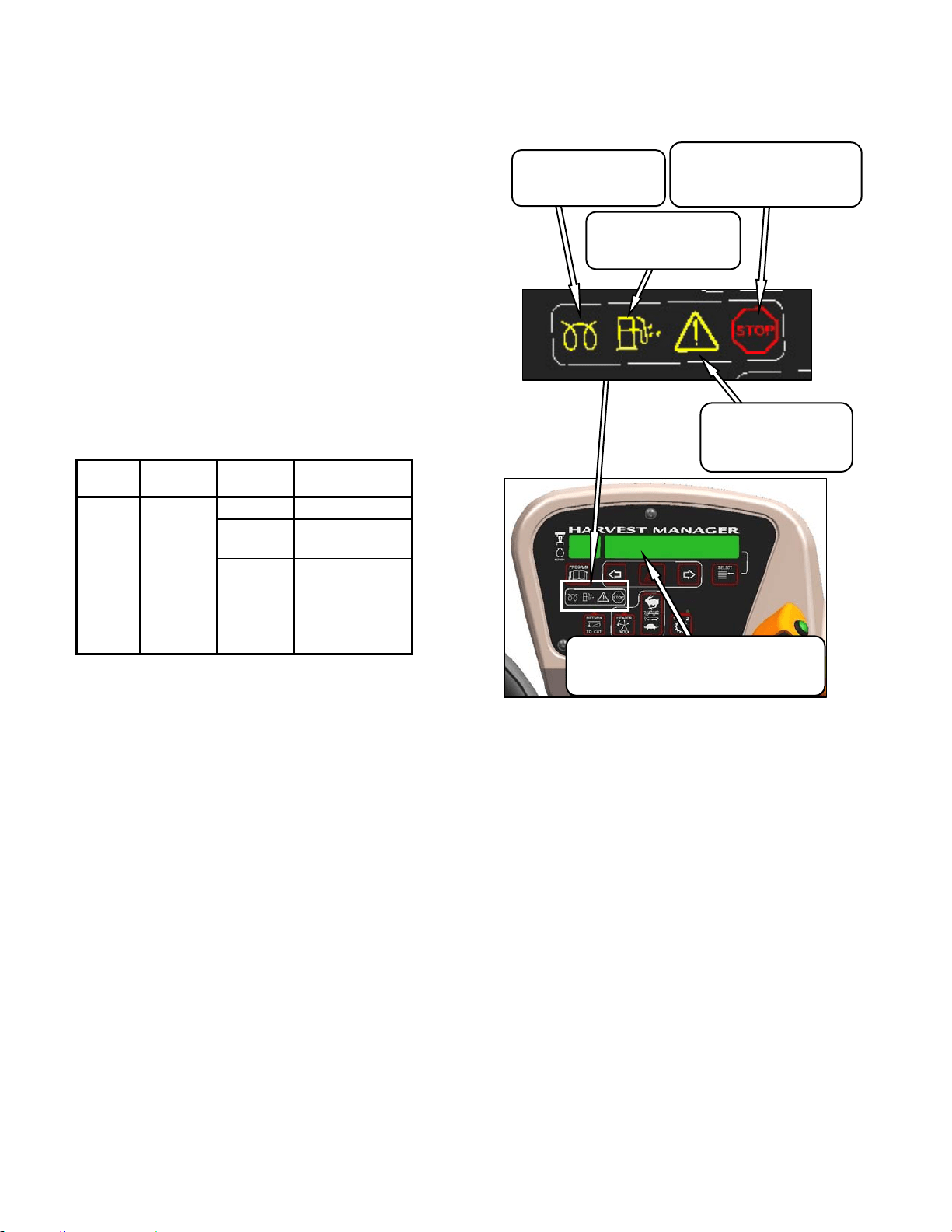
OPERATOR’S STATION
169304 52 Rev. C
6.3.5.6 Engine Oil Pressure
There is no gauge or display for engine oil
pressure. The nominal engine oil pressure is 10
psi (69 kPa) at low idle, and 55.1 psi (380 kPa)
at maximum rated speed. If the oil pressure
drops below 7.5 psi (52 kPa), a continuous loud
tone will sound and the CDM display will flash
“ENGINE OIL PRESS”. Shutdown the engine
immediately if warning occurs while operating or
if it continues for more than a few seconds after
engine startup.
6.3.5.7 Electrical
The electrical system voltage is displayed on the
CDM when selected with the select button on
the GSL handle or the select switch on the
CDM. The display indicates the condition of the
battery and alternator. Refer to table.
IGNITION ENGINE READING INDICATED
CONDITION
On
Running
13.8-15.0 Normal
> 16.0
See Note
Regulator Out of
Adjustment.
<12.5
See Note
Alternator Not
Working or
Regulator Out of
Adjustment.
Shutdown 12.0 Battery Normal.
Note: Display flashes voltage reading with single
loud tone. Repeats every 30 minutes until
condition fixed.
6.3.5.8 Engine Integrated Speed Control (ISC)
The engine operating speed can be
programmed to enable the windrower to operate
at 2400 rpm (200 below maximum) without
significantly affecting the ground or header
speeds. This is useful in where operating loads
are reduced such as in light crop conditions
which do not require the maximum engine rpm.
Reduced engine speed lowers fuel consumption,
noise levels, and exhaust emissions in addition
to reducing engine wear.
Programming instructions are given in Section
5.18.5 Cab Display Monitor (CDM)
Programming. The programmed engine speed
is activated when the header is engaged.
6.3.5.9 Engine Warning Lights
There are four engine warning lights that
illuminate if abnormal conditions occur while the
engine is running. The engine warning lights
should not be illuminated under normal
operating conditions.
DISPLAY
Displays Malfunction Code
Refer to Error Codes at End of this Manual
CAUTION
Illuminates Yellow
Do Not Operate Engine
Refer to Display Code
STOP
Illuminates Red
Stop Engine Immediately
Refer to Dis
p
la
y
Code
WATER IN FUEL
Illuminates Yellow
Service Recommended
INTAKE AIR PREHEAT
Illuminates Yellow
Wait To Start Engine
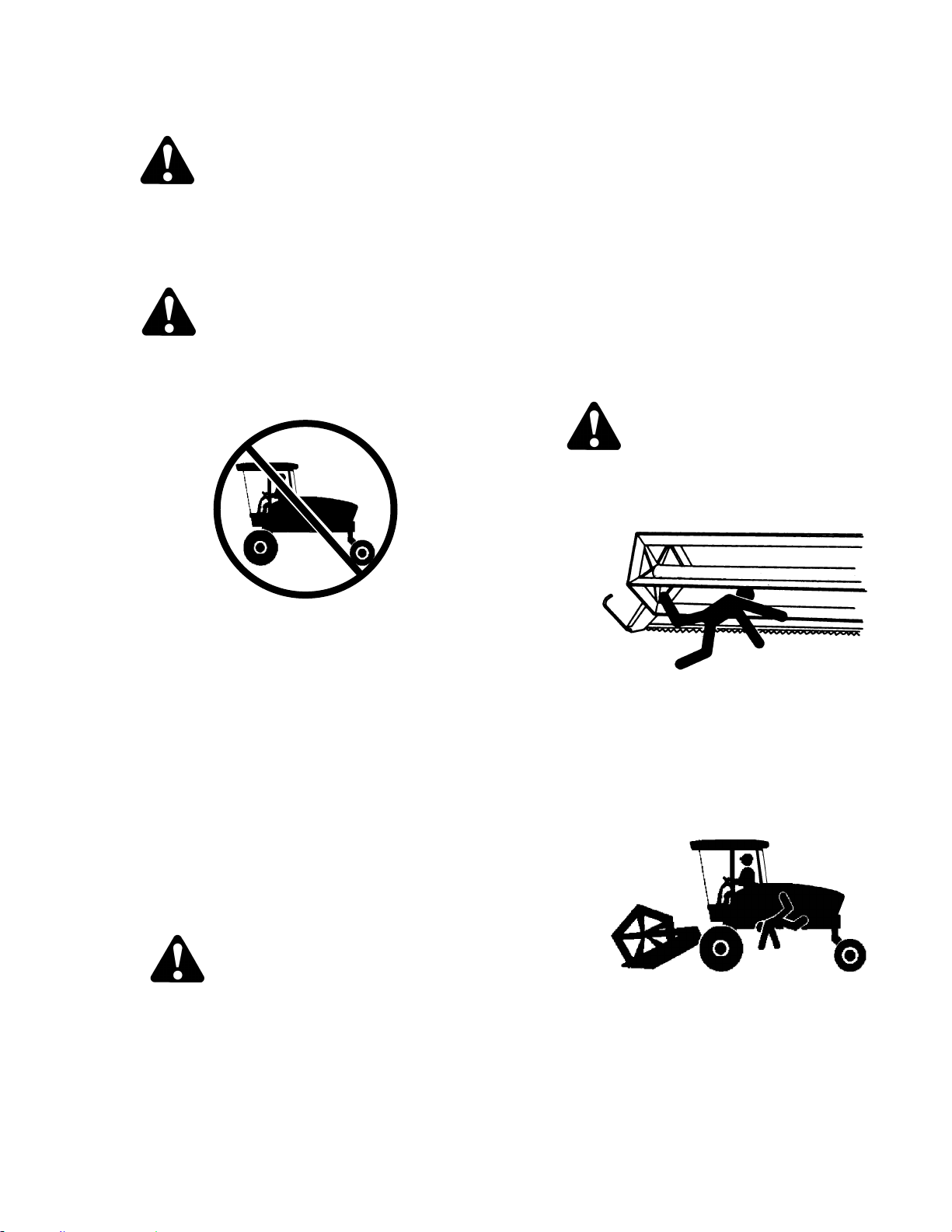
WINDROWER OPERATION
169304 53 Rev. C
6.3.6 Driving the Windrower
WARNING
Before starting engine, securely fasten your
seat belt and ensure trainer’s seat belt is
fastened if occupied. The seat belt can help
insure your safety if it is used and
maintained.
WARNING
• Avoid driving the machine with header
removed. Removing header decreases
the weight on drive wheels, reducing
steering control.
• If necessary to drive machine with
header removed, use transmission "field
speed" range, do not exceed 1500 rpm
engine speed and avoid loose gravel and
slopes.
• Never use windrower as a towing vehicle
when header is removed, except as
instructed in Section 6.3.8.2 Towing
Header with Windrower. There is
insufficient weight on the drive wheels to
provide steering control.
• Because of windrower shape
characteristics, a roll-over protected
(ROPS) cab is not required. If operating
with header removed, be aware that the
cab structure will not withstand a roll-
over.
CAUTION
HYDROSTATIC STEERING
The machine is steered hydrostatically, that
is, turning the steering wheel varies the
hydraulic flow to one drive wheel relative to
the other drive wheel. The reaction of this
type of steering is different than
conventional steering mechanisms.
IMPORTANT
With the engine running, moving the
ground speed lever out of N-DETENT
unlocks steering. Any movement of
steering wheel will then cause the
machine to move, even if the ground
speed lever has not been moved forward
or rearward from the neutral position.
Hydrostatic steering is more sensitive than
mechanical steering.
Steering is opposite to normal when
driving in reverse.
The brakes are only on when the GSL is
in N-DETENT and the steering wheel is
centered and locked.
DANGER
• Never move ground speed lever or
steering wheel until you are sure all
bystanders have cleared the area.
• Be sure area is clear before making
turns, ends of header travel in a large
arc.
• Check the operation of all controls in a
safe, clear area before starting work. Be
sure you know the capacity and
operating characteristics of this machine.
• Do not allow riders in or on the machine.
• Operate only while seated in the
operator's position.
• Never attempt to get on or off a moving
windrower.
• Avoid sudden starts and stops.
(continued next page)
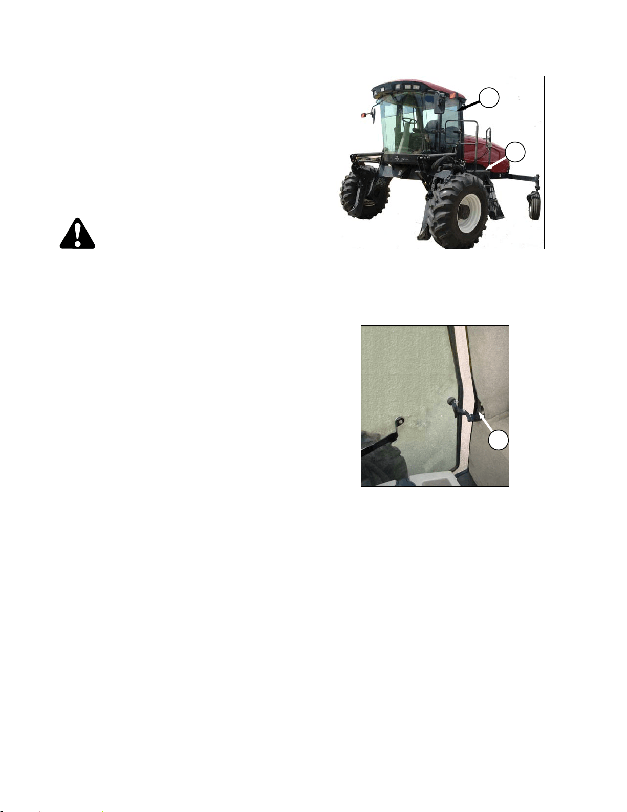
OPERATOR’S STATION
169304 54 Rev. C
• Avoid inclines, ditches and fences.
• Do not rapidly accelerate or decelerate
when turning
• Reduce speed before turning, crossing
slopes, or travelling over rough ground.
• Do not allow anyone to stand behind the
machine while operating. Foreign objects
may be forcibly ejected.
6.3.6.1 Ingress/Egress
CAUTION
• To provide more secure hand and foot
mobility, preventing slipping and
possible injury, always face the
windrower and use the hand rail when
dismounting (or mounting).
• Never attempt to get on or off a moving
windrower.
• Before leaving the operator's seat for any
reason:
• Park on level ground if possible.
• Be sure ground speed lever is in N-
DETENT and steering wheel is locked in
the straight-ahead position.
• Fully lower header and reel.
• Disengage header drives.
• Stop engine and remove key from
ignition. A child or even a pet could
engage an idling machine.
• Turn off wiper.
• Turn off lights unless required for
inspection purposes.
• Release seat belt.
• Raise armrest and steering wheel for
easier exit and re-entry.
• Lock the cab door when leaving the
windrower unattended. (When the door is
locked, it can still be opened from inside
the cab.)
a. A swing away platform and stair (A) are provided
on the LH side of the windrower to
accommodate access to the operator’s station
as well as several maintenance tasks.
b. A door (B) is provided for cab entry and exit.
c. The RH window has an overcenter swing-out
latch (C) that “unpins” for emergency exit.
C
A
B
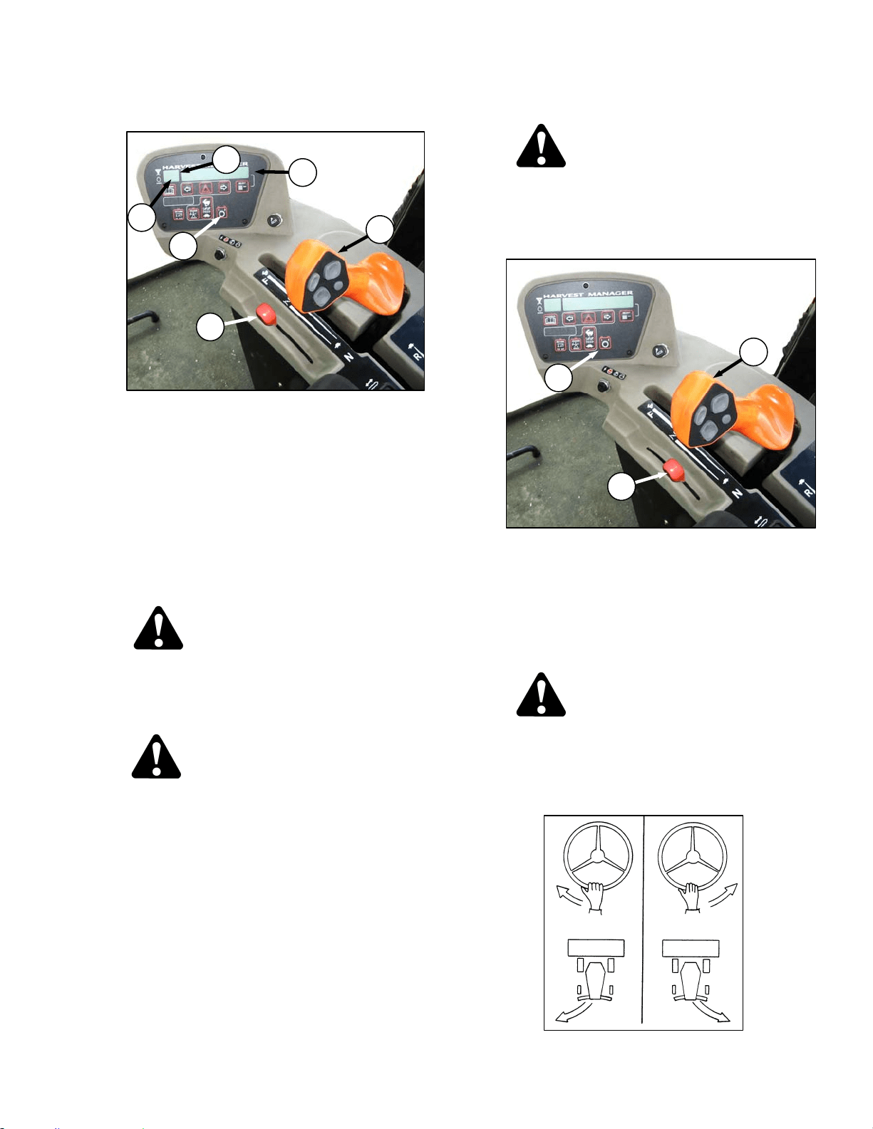
WINDROWER OPERATION
169304 55 Rev. C
6.3.6.2 Operation
a. Place GSL (A) in N-DETENT. Engine can be
running.
b. Fasten seat belt.
c. Start engine. Refer to Section 6.3.5.1 Starting.
d. Set ground speed range switch (B) to either 2 for
road speed (0-16 mph (0-25.7 km/h)), or 1 for
field speed (0-11 mph (17.7 km/h)). CDM will
display an engine status at (C).
e. Slowly push throttle (D) to full forward (operating
speed). CDM should display 2600-2650 RPM at
(E).
CAUTION
Check again to be sure all bystanders have
cleared the area.
f. Slowly move the GSL (A) forward to desired
speed which will be displayed at (F).
CAUTION
Operate both steering wheel and ground
speed lever slowly for familiarization. Avoid
the common tendency of new operators to
over-steer.
NOTE
The windrower can be equipped with an
automatic steering system for use in the
field. The Auto-Steer is available as an
option and can be installed by an Auto-
Steer dealer. The GSL has been pre-
wired at the factory with a switch. Also
see Section 9.14 AUTO-STEER.
6.3.6.2.1 Reverse
WARNING
Back up slowly. Steering is opposite to
normal when reversing. Hold steering wheel
at the bottom and turn wheel in direction you
want the rear of the machine to travel.
a. Set ground speed-range switch (B) to 1.
b. Move throttle lever (D) to a mid-range position.
NOTE
Reversing in low speed-range and at
reduced engine speed is recommended
since steering will be less sensitive than at
higher speed settings.
CAUTION
Check again to be sure all bystanders have
cleared the area.
c. Move the GSL (A) rearward to desired speed.
d. Steer as shown.
D
C
A
E
B
F
B
D
A
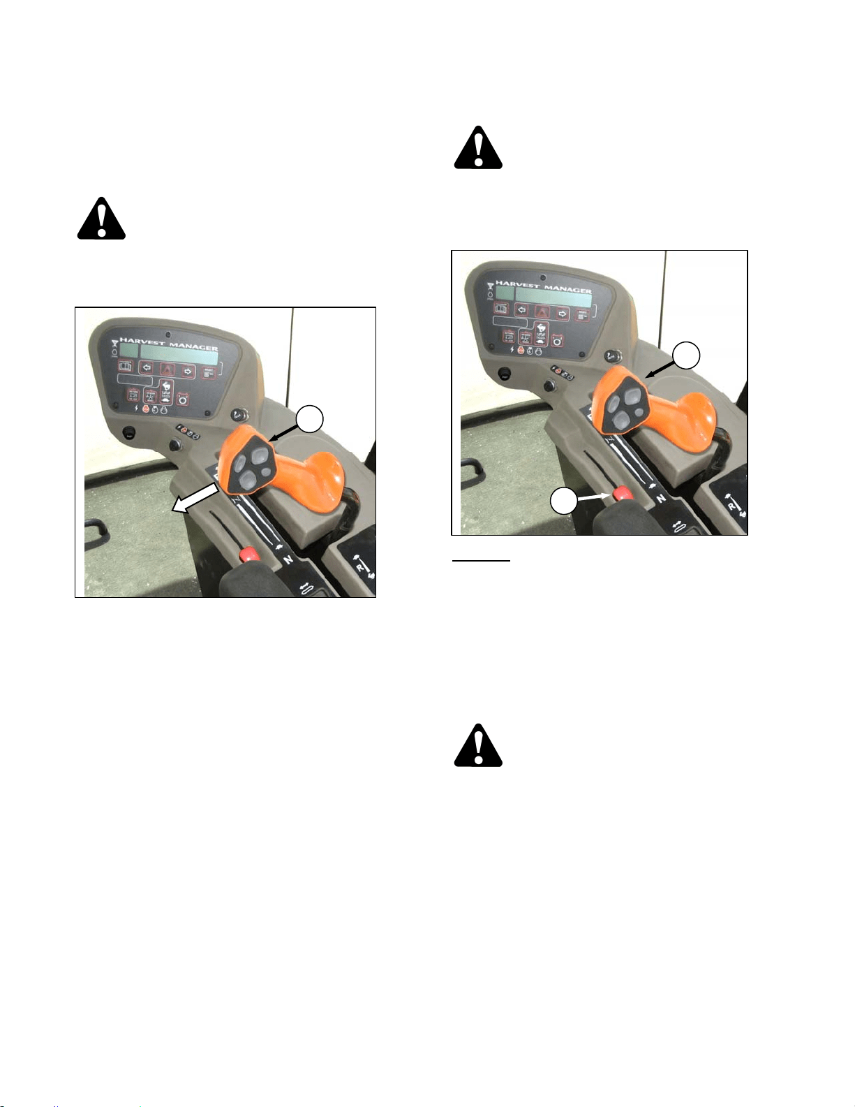
OPERATOR’S STATION
169304 56 Rev. C
6.3.6.2.2 Spin Turn
Hydrostatic steering gives the operator
significantly more manoeuvrability than
mechanical steering. To make a spin turn, refer
to illustration and proceed as follows:
CAUTION
Be sure area is clear before making turns.
Although windrower pivots "on the spot",
ends of header travel in a large arc.
a. Move the GSL (A) out of N-DETENT towards the
seat and hold.
b. Slowly turn the steering wheel in the desired
direction of turn. The windrower will pivot
between the drive wheels.
c. To stop the turn, slowly turn the steering wheel
back to its centered position.
d. To increase the turn radius, slowly move the
GSL away from neutral. Remember that this will
increase ground speed as well.
e. To stop the turn, move GSL back to neutral, and
return the steering wheel to center.
6.3.6.2.3 Stopping
WARNING
Do not move ground speed lever rapidly
back to neutral. Operator may be thrown
forward by sudden stop. Always wear seat
belt when operating windrower.
a. SLOWLY
return the GSL (A) to neutral and into
N-DETENT.
b. Turn steering wheel until it locks.
c. Move throttle lever (D) to low idle position.
NOTE
Avoid unnecessary idling. Stop engine if it
will be idling for longer than 5 minutes.
d. Brakes are automatically engaged when
steering wheel is locked in neutral position.
CAUTION
Park on a flat, level surface, header on the
ground and the ground speed lever in N-
DETENT.
IMPORTANT
Before stopping engine, run at low idle for
approximately five minutes to cool hot
engine parts (and allow turbocharger to
slow down while engine oil pressure is
available).
e. Turn key counter-clockwise to OFF position.
A
D
A
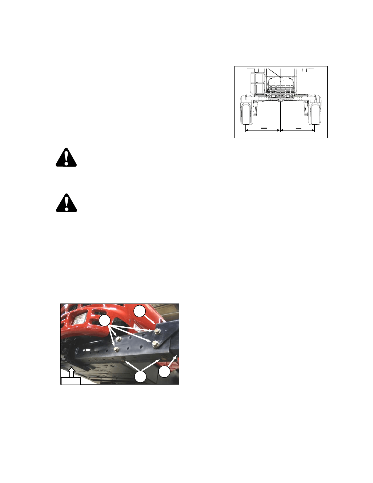
WINDROWER OPERATION
169304 57 Rev. C
6.3.7 Adjustable Caster Tread Width
(Optional)
As an option, the rear casters can be adjusted to
a narrow tread width to allow loading and
shipping without having to remove them. A
narrow tread width also suits smaller headers by
allowing more space to the uncut crop and
provides more maneuverability around poles,
irrigation inlets, or other obstacles. A wider
tread width is useful in heavy crops that produce
large windrows so that run-over is reduced.
To adjust the caster tread width, refer to the
following illustrations and proceed as follows:
CAUTION
Park on a flat, level surface, header on the
ground and the ground speed lever in N-
DETENT position.
DANGER
Stop engine and remove key from ignition
before leaving operator's seat for any
reason. A child or even a pet could engage
an idling machine.
a. Raise rear of windrower slightly so that most of
the weight is off the casters, using a jack or
other lifting device under the frame where
shown.
NOTE
Lifting device should have lifting capacity
of at least 5000 lb (2270 kg).
b. Remove bolts and washers (A) and (B) from left
and right sides of the walking beam.
c. Slide walking beam extensions (C) inboard or
outboard equal amounts and align holes at
desired position.
NOTE
Illustration shows widest tread width
adjustment.
IMPORTANT
Center of tread width must be aligned with
center of windrower.
d. Position bracket (D) and install bolts (A) and (B).
The two shorter bolts are installed at the back
inboard locations. Torque as follows:
1. Snug bottom bolts (B).
2. Tighten back bolts (A) to 330 ft·lbf (447
N·m).
3. Tighten bottom bolts (B) to 330 ft·lbf (447
N·m).
e. Lower windrower and remove lifting device.
f. Retorque bolts at 5 and 10 hours of operation.
C
D
LIFT
A
B
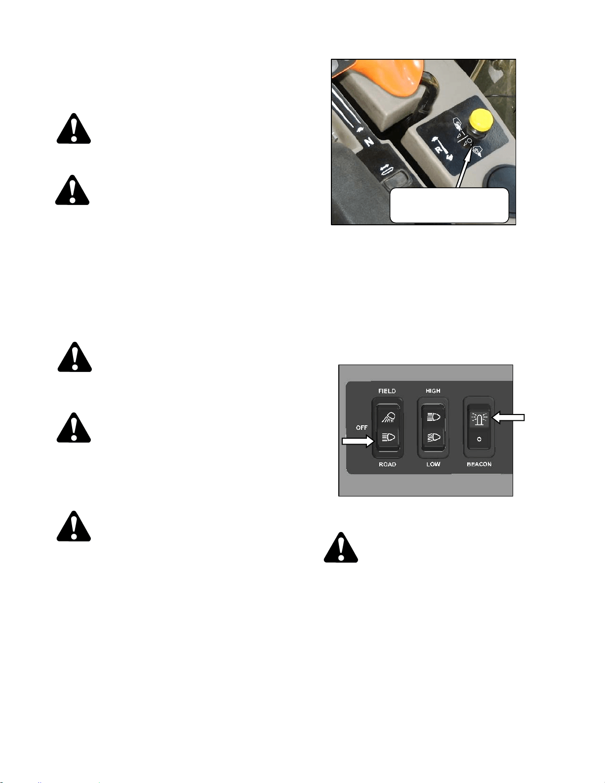
OPERATOR’S STATION
169304 58 Rev. C
6.3.8 Transporting
6.3.8.1 Driving On Road
WARNING
Collision between windrower and other
vehicles may result in injury or death.
WARNING
When driving windrower on public roadways:
• Obey all highway traffic regulations in
your area. Use pilot vehicles front and
rear of windrower if required by law.
• Use slow moving vehicle emblem and
flashing warning lights unless prohibited
by law.
• If width of attached header impedes other
vehicle traffic, remove header and install
a MacDon approved weight box.
CAUTION
Check local laws for width regulations and
lighting and marking requirements before
transporting on roads.
WARNING
Do not drive windrower on a road or highway
at night, or in conditions which reduce
visibility, such as fog or rain. The width of
the windrower may not be apparent under
these conditions.
CAUTION
Operate both steering wheel and ground
speed lever slowly for familiarization.
Remember that steering is more sensitive
when speed-range control is in Road Speed
Position. Avoid the common tendency of
new operators to over-steer.
a. Ensure HEADER DRIVE switch is pushed to off
position.
b. Before driving windrower on a roadway:
1. Clean flashing amber lamps, red tail lamp
and head lamps and check that they work
properly.
2. Clean all reflective surfaces and slow
moving vehicle emblems.
3. Adjust interior rear view mirror and clean
windows.
c. Push LIGHT switch to ROAD position to activate
lamps. .
WARNING
Always use these lamps on roads to provide
warning to other vehicles. Do not use field
lamps on roads, other drivers may be
confused by them.
d. Push BEACON switch to on to activate beacons
(North America optional).
(continued next page)
HEADER DRIVE
ENGAGE – Pull Up
DISENGAGE – Push Down
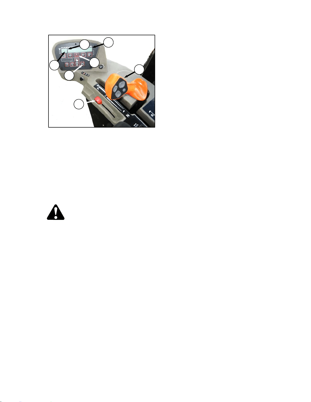
WINDROWER OPERATION
169304 59 Rev. C
e. Press switch (A) on CDM to activate hazard
lights (Export optional).
f. Push ground speed range switch (B) for road
speed. CDM will display ROAD GEAR at (C),
and LED over 2 will light up.
g. Slowly push throttle (D) to full forward (operating
rpm). CDM should display 2600-2650 at (E).
h. Slowly move the GSL (F) forward to desired
ground speed which will be displayed also at (F).
i. If towing a header, refer to Section 6.3.8.2
Towing Header with Windrower.
WARNING
To avoid serious injury or death from loss of
control:
• Do not make abrupt changes in steering
direction.
• Anticipate turns and steep slopes by
slowing down well in advance.
• Do not rapidly accelerate or decelerate
while turning.
• When travelling on steep slopes:
i) Move ground speed lever closer to
neutral to reduce speed.
ii) Lower header.
iii) Move GROUND SPEED RANGE
switch to low range.
• With header removed, steering control is
reduced if weight is not added to drive
wheels. If you must drive the windrower
without header or MacDon weight
system;
i) Operate in low speed range.
ii) Do not exceed 1500 rpm engine
speed.
iii) Avoid loose gravel and slopes.
iv) Do not tow a header.
v) If control of machine is lost,
immediately pull ground speed lever
to neutral.
D
C
F
E
B
F
A
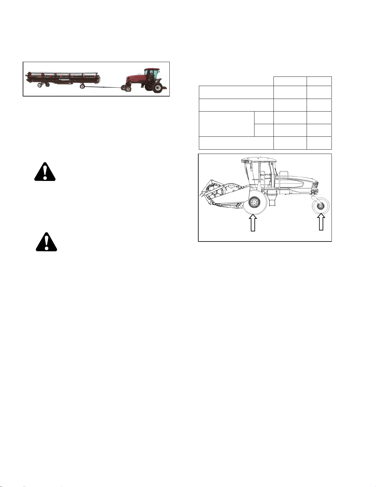
OPERATOR’S STATION
169304 60 Rev. C
6.3.8.2 Towing D-Series Header with
Windrower
The M100 windrower can be used to tow a
MacDon Harvest Header with the Slow Speed
Transport option installed, provided the
Transport Drawbar and the Weight Box options
are installed on the windrower. See your
MacDon dealer for further information if these
options are not installed on your M100
windrower.
WARNING
Harvest Header with Transport Option
The windrower without the header must not
be used to tow headers due to reduced
traction and possible loss of control unless
the Weight Box option is installed on the
windrower.
CAUTION
• To tow a header for transporting with an
M100 Self Propelled Windrower, the
header must be equipped with the
appropriate equipment to comply with all
local regulations.
• Before each towing trip, a pre-trip
inspection must all be conducted to
verify that all signal lighting and safety
equipment is installed and functioning
properly.
• Do not connect any towed implement
except for:
o 30-35’ D-Series headers equipped
with slow-speed transport
package or
o Header transport trailers for 20-
25’ D-Series headers.
• Tongue weight must not exceed 500 lbs.
• Do not exceed the specified Combined
Gross Vehicle Weight (CGVW).
• To prevent machine damage and/or loss
of control, it is essential that the machine
be equipped such that weights are within
the following limits:
LB KG
MAX GVW (includes
mounted implements)
17.750 8,050
MAX CGVW (includes towed
and mounted implements).
20,200 9,160
WEIGHT “A” ON
BOTH DRIVE
WHEELS
MAX 16,300 7,390
MIN 9,150 4,150
MAX WEIGHT “B” ON
BOTH CASTER TIRES
3,550 1,610
A
B
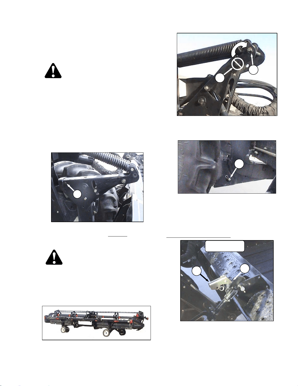
WINDROWER OPERATION
169304 61 Rev. C
6.3.8.2.1 From Field to Transport Mode
6.3.8.2.1.1 Detach Header from Windrower
a. Set header on the ground (field position).
DANGER
Stop engine and remove key from ignition
before leaving operator's seat for any
reason. A child or even a pet could engage
an idling machine.
b. Disconnect hydraulic and electrical connections:
1. Left Side - Store hydraulic hoses and
electrical cable into the storage position.
See Header Operator’s Manual.
2. Right side – Release the multi link and place
into storage on windrower. See Header
Operator’s Manual.
c. Retrieve temporary lift pin from storage location
on weight box and install into rear hole
(A) at the
top of the lift arms for additional lift height for
transport wheel deployment.
DANGER
To avoid bodily injury from fall of raised
header, always engage header lift cylinder
stops when working on or around raised
header.
d. Raise header to full height, stop engine, and
engage safety locks on lift cylinders.
e. Deploy header slow speed transport system.
See Header Operator’s Manual.
f. Remove float pin from engaged position (B) and
insert in storage location (C). Secure with lynch
pin.
g. Remove pins (D) from lower end of lift linkages.
NOTE
Pins (D) are also used to secure weight
box to windrower linkage.
h. Disconnect the center link as follows:
HYDRAULIC LINK – OPTION
1. Pull up on latch (E) and locate latch into
notch (F) on top of hook.
(continued next page)
D
D60 SHOWN
E
F
A
B
C
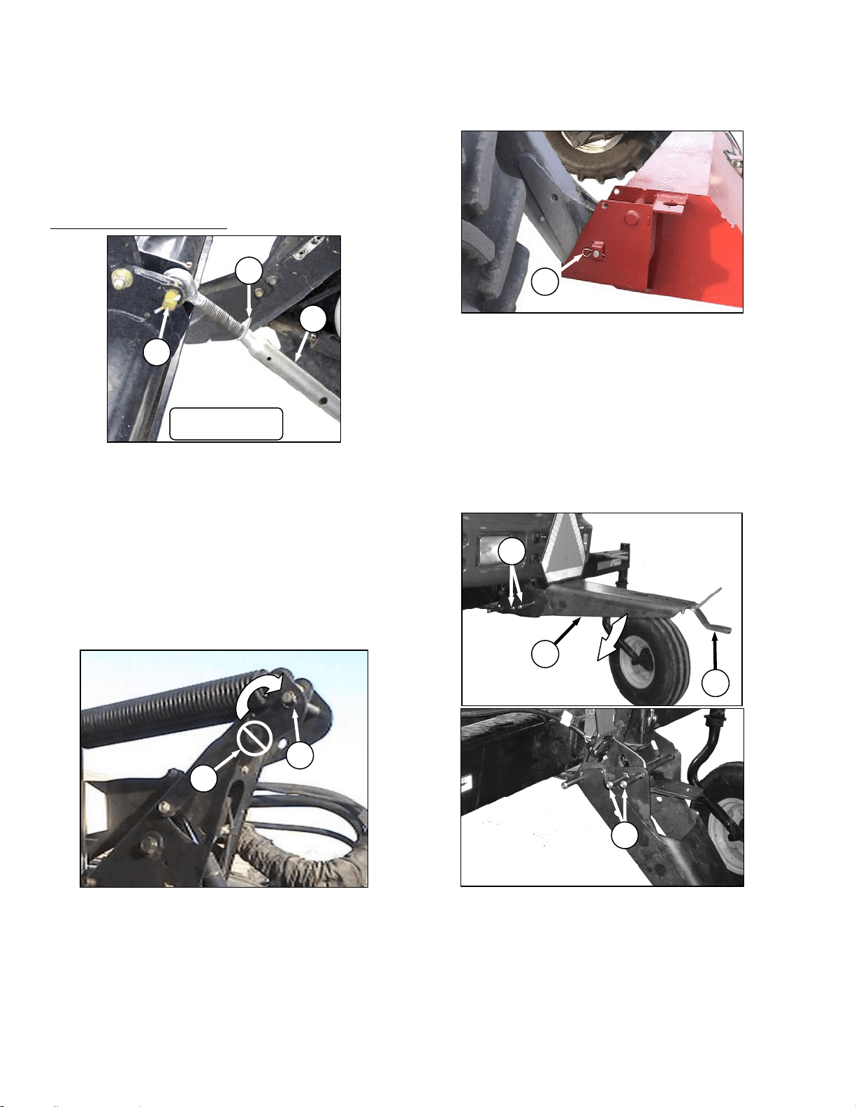
OPERATOR’S STATION
169304 62 Rev. C
2. Release the safety lock on the header lift
cylinders.
3. Lower header down onto the transport
wheels.
4. Disengage the top link from the header.
Use the header tilt switch to release load on
the cylinder if necessary.
MECHANICAL LINK – M150
1. Loosen nut (G) and rotate barrel (H) to
relieve load on link.
2. Remove cotter pin on pin (J), and remove
pin to disconnect from windrower. Re-install
pin in header.
i. Back windrower away from header.
j. Remove tow-bar sections from storage locations
on header, assemble, and attach to header.
See Header Operator’s Manual.
6.3.8.2.1.2 Attach Weight Box To Windrower.
IMPORTANT
To prevent damage to the lift system when
lowering header lift linkages without a
header or weight box attached to
windrower, ensure that float engagement
pin is installed in storage location (C), and
not installed at hole location (B).
a. Drive windrower so that windrower lift arms are
positioned into the weight box pockets.
b. Raise lift arms slightly.
c. Stop engine and remove key.
d. Install locking pins (D) into pockets and thru
windrower header lift linkages. Secure with
hairpin.
NOTE
Pins (D) were previously removed from
the header lift linkage lower end.
e. At rear of windrower, lower the drawbar bracket
from field position as follows:
1. Hold drawbar support (K) and remove the
two pins (L) at the forward end.
2. Lower support to position shown and re-
install the two pins in uppermost pair of
holes in support.
3. Alternate drawbar (M) can be removed if
desired.
J
H
G
D60 SHOWN
D
B
C
G
K
L
M
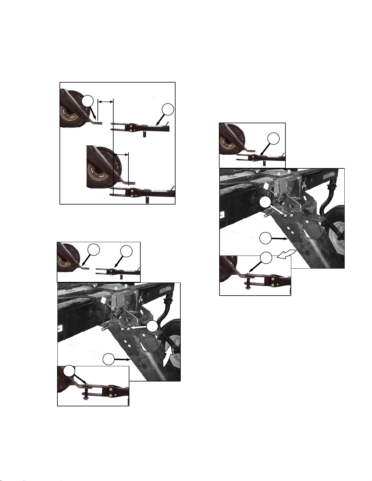
WINDROWER OPERATION
169304 63 Rev. C
f. Attach Tow-Bar To Windrower
The M100 Transport drawbar provides
approximately 12 in. (300 mm) of fore/aft
movement to ease the attachment of a towed
implement.
a. Back the windrower up to the tow-bar (A) so that
drawbar hole (B) is within 6 in. (150 mm) of the
tow-bar clevis pin.
b. Stop engine and remove key.
c. If the tow-bar (A) is too far from the drawbar (B),
remove pin (C), lift the drawbar support (D) until
the tow-bar clevis aligns and then install the
drawbar pin (E).
d. Start engine and gently reverse the windrower
until the drawbar support pivots down into
transport position.
e. Stop engine and remove key.
f. Reinstall pin (C) to secure drawbar support, and
proceed to step k.
IMPORTANT
Ensure lynch pins are secure in all three
pins and that the drawbar pin is also
secured by a locking pin.
g. If the tow-bar (A) is too close to the windrower,
remove pin (F), lower the drawbar support (D)
until the tow-bar clevis aligns and then install the
drawbar pin (E).
h. Start engine and gently drive the windrower
forward until the drawbar support pivots up into
transport position.
i. Stop engine and remove key.
j. Reinstall pin (F).
(continued next page)
OR
0 to 6 in. (150 mm)
0 to 6 in. (150 mm)
B
A
C
D
B
A
E
F
D
A
E
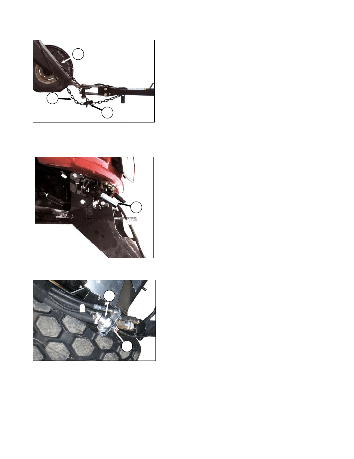
OPERATOR’S STATION
169304 64 Rev. C
k. Connect safety chain (G) through the slot (H) in
drawbar support and securely attach the hook
(J) to the chain. Leave enough slack to allow the
hitch to pivot.
l. At the drawbar, connect the tow-bar harness
plug (K) to the receptacle on the windrower.
m. At the LH float spring tower, attach connector (L)
on windrower harness to towing harness
receptacle (M).
n. Confirm that the flashing amber and signal lights
on header function properly.
o. Before moving the machine: double check that
all pins are secure, the drawbar and hitching
components are not showing signs of damage,
and that all safety equipment is installed and
fully functional.
K
L
M
G
H
J
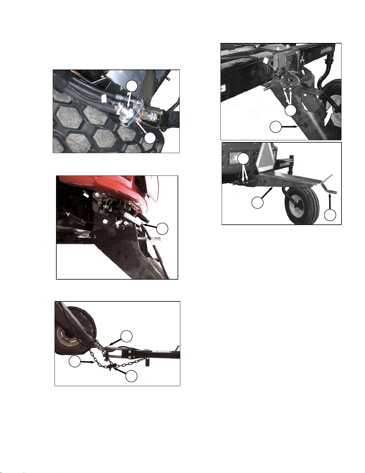
WINDROWER OPERATION
169304 65 Rev. C
6.3.8.2.2 From Transport Mode To Field
Operation
a. Shutdown windrower and remove key.
b. Disconnect windrower harness (A) from towing
harness receptacle (B) in LH float spring tower.
c. Disconnect electrical harness (C) from
windrower and store harness on tow-bar.
d. Undo lock (D) and remove safety chain (E) from
drawbar and remove clevis pin (F).
e. Move tow-bar off drawbar.
f. At rear of windrower, remove pins (G), lift
drawbar support (H) to horizontal position, and
re-install pins as shown.
g. Alternate drawbar (J) is used for attaching tow
behind swath roller.
IMPORTANT
Do not use alternate drawbar for any other
purpose.
h. Disassemble tow-bar and store on header. See
Header Operator’s Manual.
(continued next page)
C
A
B
G
H
H
G
J
E
F
D
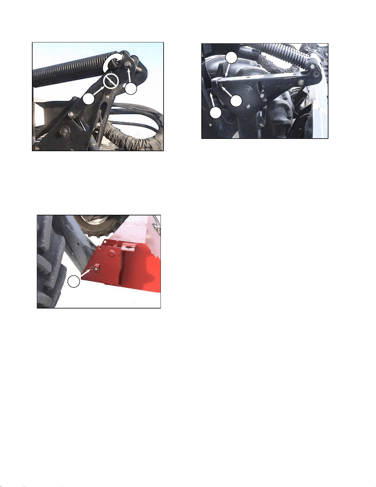
OPERATOR’S STATION
169304 66 Rev. C
IMPORTANT
To prevent damage to the lift system when
lowering header lift linkages without a
header or weight box attached to
windrower, ensure that float engagement
pin is installed in storage location (K), and
not installed at hole location (L).
i. Remove pins (M) securing lift linkages to weight
box, and retain pins for attaching header to
windrower.
j. Lower weight box onto blocks and back away.
k. Attach header to windrower. Refer to Section
6.5.1 Header Attachment.
l. Convert header into field position. See Header
Operator’s Manual for procedure.
m. Start engine and lower header to ground.
Continue to retract lift cylinders so that member
(N) lifts off link (O).
n. Remove temporary lift pins (P) from lift arms and
install pins into storage holes in weight box.
o. Before operating the machine, double check that
all pins are secure, and that all safety equipment
is installed and fully functional.
p. Proceed with operation of header.
M
L
K
P
N
O
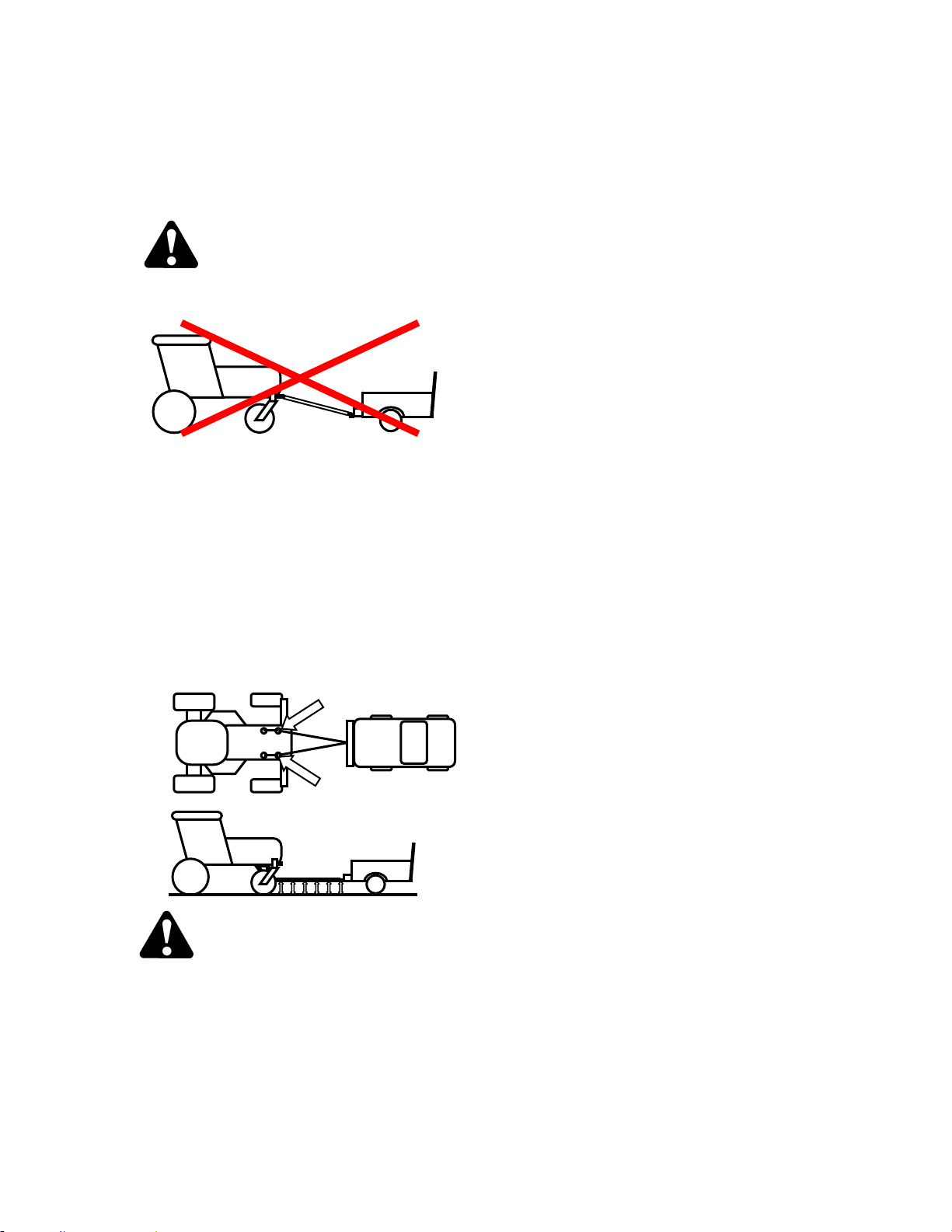
WINDROWER OPERATION
169304 67 Rev. C
6.3.8.3 Towing the Windrower
In emergency situations, for example, towing out
of a field or into a shop, windrower may be
towed without a trailer, providing the following
precautions are followed:
WARNING
A proper towing apparatus is critical to safe
towing. Use the following guidelines:
• Do not attach directly from hitch to
walking beam. Slope of tow bar will not
provide proper transfer of braking force
to windrower, causing loss of control.
• For proper steering, towing apparatus
should be attached to both left and right
hand frame members and should attach
to tow bar at same height as towing
vehicle hitch.
• Towing apparatus should be removed for
field operation, to avoid interference with
windrow.
WARNING
With final drives disengaged, the windrower
may roll on a sloped surface. Before
disengaging final drives, attach windrower to
towing vehicle. After towing, engage drives
and ensure GSL is in N-DETENT before
detaching from towing vehicle.
IMPORTANT
Failure to disengage final drives before
towing will result in serious transmission
damage.
IMPORTANT
Do not exceed 16 mph (26 km/h) when
towing windrower. Do not use this towing
method for normal transporting of
windrower. Even with final drives
disengaged, rolling speeds of more than
16 mph (26 km/h) will cause final drive
gears to run at excessive speeds, possibly
destroying the unit.
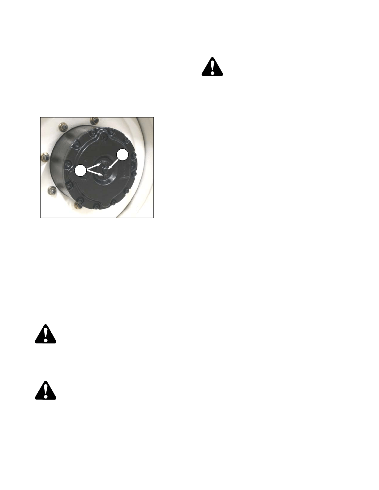
OPERATOR’S STATION
169304 68 Rev. C
6.3.8.4 Final Drives
Disengage and engage final drives as follows:
a. Remove the two hex bolts (A) at center of drive
wheel.
b. Remove cap (B) and flip over so that dished side
faces in. The cap depresses a pin which
disengages the gearbox.
c. After towing, reverse cover (A) to re-engage final
drives. Be sure plunger at center of wheel pops
out to engage drive.
6.3.9 Storage
NOTE
For short term storage (3-4 weeks), it is
recommended to shut off the battery
disconnect switch to reduce/minimize
battery drain. See 7.10.1.5 Battery
Disconnect Switch.
At the end of each operating season:
a. Clean the windrower thoroughly.
WARNING
Never use gasoline, naphtha or any volatile
material for cleaning purposes. These
materials are toxic and/can be flammable.
b. Store windrower in a dry protected place.
CAUTION
Never operate engine in a closed building.
Proper ventilation is required to avoid
exhaust gas hazards.
c. Remove the battery. Refer to Section 7.10.1.5.
d. Bring to full charge and store in a cool, dry place
not subject to freezing.
CAUTION
Remember when working around storage
batteries that all of the exposed metal parts
are "live". Never lay a metal object across
the terminals because a spark and short
circuit will result.
e. If stored outside, always cover windrower with a
waterproof tarpaulin or other protective material.
This will protect the switches, instruments, tires,
etc. from inclement weather.
f. If no cover is available; seal air cleaner intake
and exhaust pipe with plastic bags and/or
waterproof tape.
g. If possible, block up windrower to take weight off
tires. If it is not possible to block up the machine,
increase tire pressure by 25% for storage.
Adjust to recommended operating pressure
before next use.
h. Repaint all worn or chipped painted surfaces to
prevent rust.
i. Lubricate the windrower thoroughly, leaving
excess grease on fittings to keep moisture out of
bearings. Apply grease to exposed threads and
sliding surfaces of components.
j. Check for worn components and repair. Tighten
loose hardware and replace any missing
hardware. See Specifications section for torque
charts.
k. Check for broken components and order
replacements from your dealer. Attention to
these items right away will save time and effort
at beginning of next season.
l. Add approved rust inhibitor to the engine oil in
accordance with the manufacturer’s instructions.
Run engine to operating temperature to mix
inhibitor with oil, unless otherwise specified.
m. To prevent condensation, fill hydraulic oil
reservoir to filler neck with approved hydraulic
system oil. Refer to Section 7.11.1 Hydraulic Oil.
n. Test engine coolant anti-freeze concentration to
ensure it is sufficient to protect engine against
lowest expected temperature.
B
A
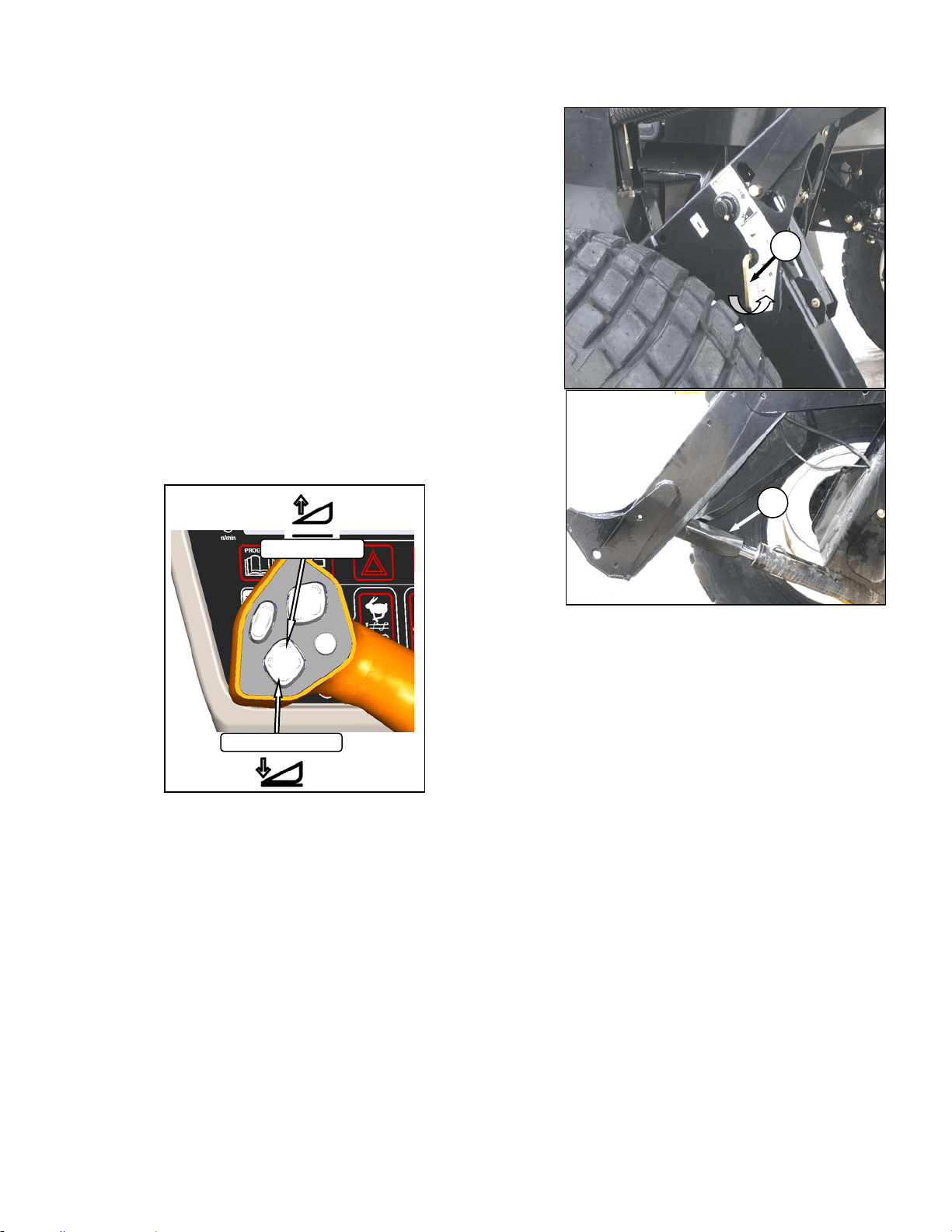
HEADER OPERATION
169304 69 Rev. C
6.4 HEADER OPERATION
The M100 Windrower is designed to use the
MacDon A Series auger header with hay
conditioner, and D Series Rigid Draper headers
with or without hay conditioners. This section
describes the attachment and detachment
procedures and operating instructions for these
header types.
6.4.1 Header Lift Cylinder Stops
Cylinder stops are located on both header lift
cylinders on the windrower. To avoid bodily
injury or death from fall of raised header, always
engage cylinder stops before going under
header for any reason. Engage cylinder stops
as follows:
a. Press HEADER UP swich to raise header to
maximum height.
NOTE
If one end of the header does not raise
fully, the lift cylinders require re-phasing.
Proceed as follows:
1. Hold the up switch until both cylinders stop
moving.
2. Press HEADER DOWN switch to lower the
header all the way down, and continue to
hold the switch for 3-4 seconds.
3. Raise the header again to full height.
b. Pull lever (A) and rotate toward header to
release and lower cylinder stop (B) onto
cylinder. Repeat for both lift cylinders.
c. To store, turn lever (A) away from header to
raise stop until lever locks into vertical position.
B
A
HEADER UP
HEADER DOWN
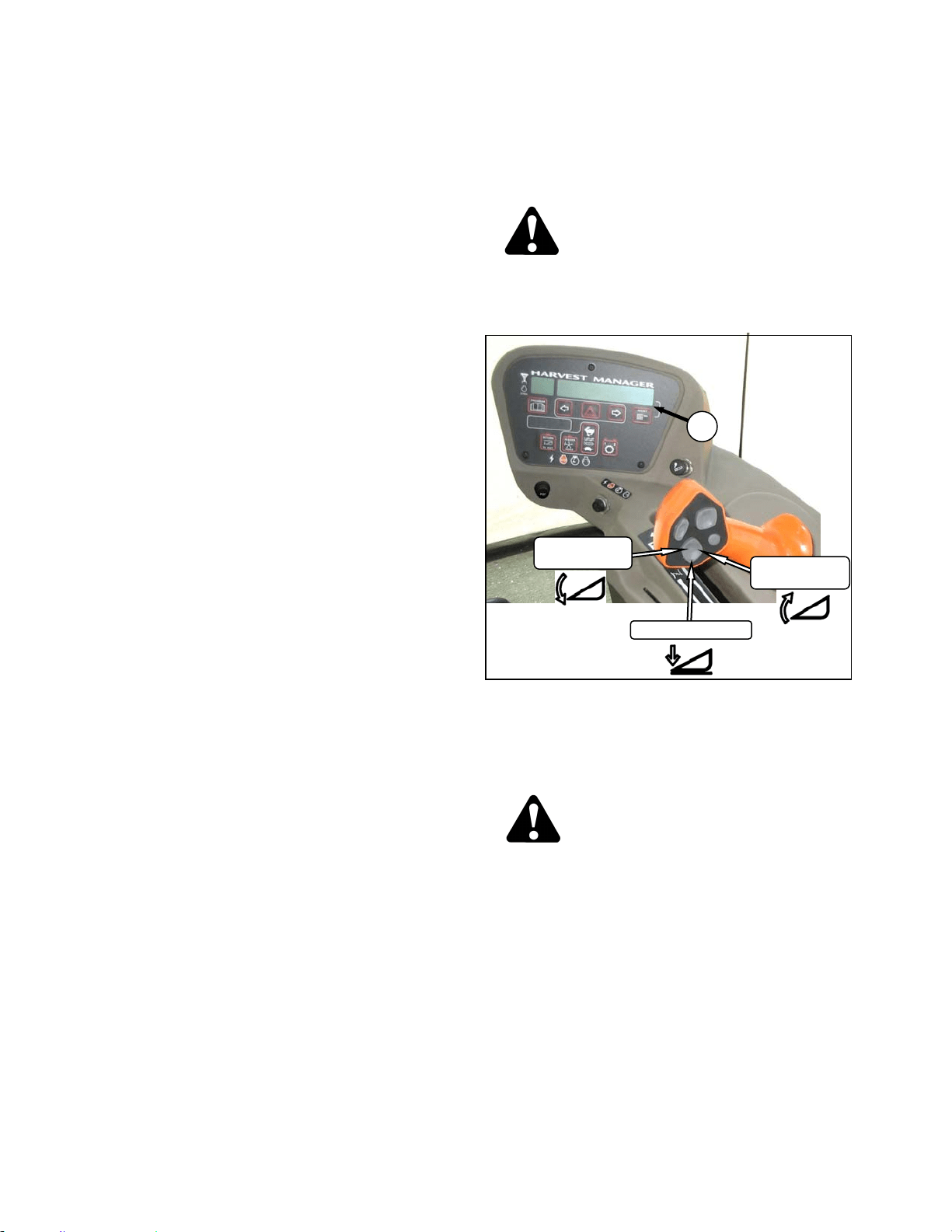
HEADER OPERATION
169304 70 Rev. C
6.4.2 Header Flotation
Float is intended for cutting crops that require
the cutterbar to be in contact with the ground.
Optimum float is for the cutterbar to maintain
contact with the ground with minimum bouncing
and scooping or pushing soil.
The machine will perform best with minimum
extra weight on the header.
IMPORTANT
To avoid frequent breakage of sickle
components, scooping soil, or soil build-up
at cutterbar in wet conditions, header float
should be set as light as possible without
causing excessive bouncing. When float
setting is light, it may be necessary to use
a slower ground speed to avoid excessive
bouncing and leaving a ragged cut.
IMPORTANT
The stabilizer wheels are designed to
minimize bouncing at the header ends and
not “float” the header. Refer to the D60
Harvest Header / FD70 FlexDraper
Operator’s Manual for adjustment details.
6.4.2.1 Float Operating Guidelines
When working with the cutterbar on the ground;
• Set center link to mid-range position. Refer
to Section 6.4.4 Header Angle.
• In rocky fields, adjust skid shoes down to
raise guards when operating at flattest
header angle to minimize scooping rocks.
• Adjust header height or adjust header angle
to minimize pushing soil.
6.4.2.2 Float Adjustment
The float adjustment uses drawbolts to change
the tension on the springs in the lift linkages.
a. Check header float as follows:
CAUTION
Check to be sure all bystanders have cleared
the area.
1. Start the engine.
2. If hydraulic center link is installed, use the
HEADER TILT SWITCHES to set center link
to mid-range position (05.0 on CDM) (A).
3. Using HEADER DOWN switch, lower
header fully with lift cylinders fully retracted.
DANGER
Stop engine and remove key from ignition
before leaving operator's seat for any
reason. A child or even a pet could engage
an idling machine.
4. Shut down engine and remove key.
5. Grasp the divider rod and lift. The force to
lift should be as noted in the following table,
and should be approximately the same at
both ends.
(continued next page)
HEADER DOWN
HEADER
TILT UP
HEADER
TILT DOWN
A
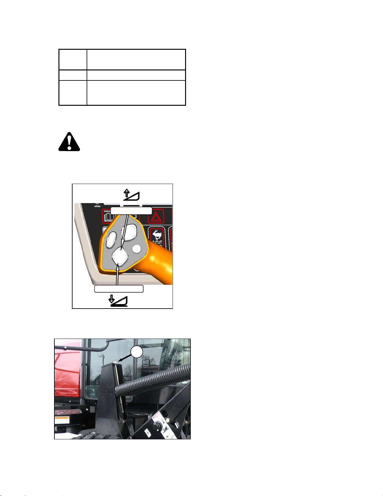
HEADER OPERATION
169304 71 Rev. C
HEADER FORCE TO LIFT CUTTERBAR AT
ENDS WITH LIFT CYL FULLY
RETRACTED
Auger 75-85 lbf (335-380 N)
Draper
50-70 lbf (220-310 N) With
Stabilizer/Transport Wheels
Raised (if equipped).
b. If necessary, adjust the float with the drawbolts
as follows:
CAUTION
Check to be sure all bystanders have cleared
the area.
1. Start engine.
2. Using HEADER UP switch on GSL, Raise
the header fully, shut down the engine, and
remove the key.
3. Turn drawbolt (D) clockwise to increase float
(makes header lighter) or counterclockwise
to decrease float (makes header heavier).
4. Recheck the float as described on previous
page.
D
HEADER UP
HEADER DOWN
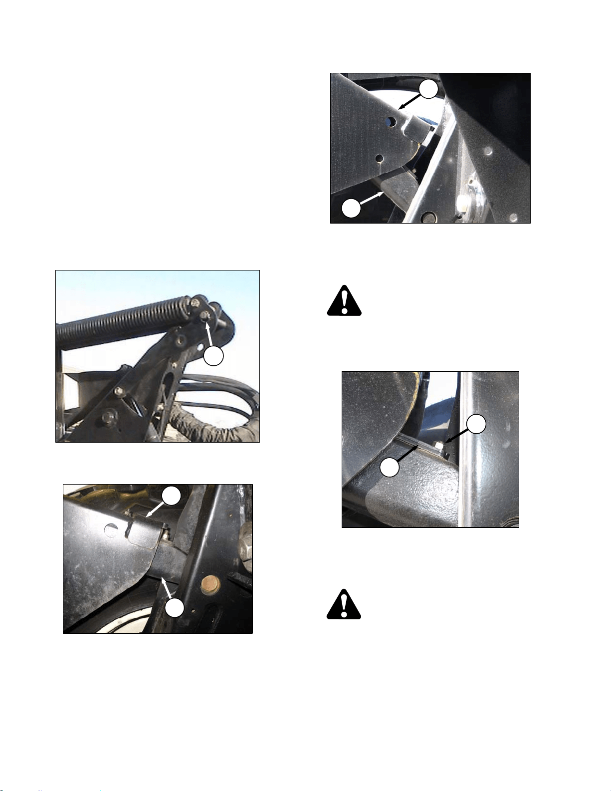
HEADER OPERATION
169304 72 Rev. C
6.4.2.3 Leveling
The windrower linkages are factory set to
provide the proper level for the header and
should not normally require adjustment. If the
header is not level, perform the following checks
prior to adjusting the leveling linkages. The float
springs are not used to level the header.
a. Raise header to full height and keep HEADER
UP switch depressed to ensure lift cylinders are
phased.
b. Check drive wheel tire pressures.
c. Check and set float adjustment. Refer to
previous sections.
d. If header is not level after the above checks,
adjust as follows:
1. Place float pins in locked out location (A).
2. Park windrower on level ground.
3. Set header approximately 6 inches (150
mm) off ground and check that member (B)
is on link (C) as shown. Note high and low
end of header.
4. Place wooden blocks under header
cutterbar and legs.
5. Lower header onto blocks so that members
(B) lift off links (C). Stop engine.
DANGER
Stop engine and remove key from ignition
before leaving operator's seat for any
reason. A child or even a pet could engage
an idling machine.
6. On high side, remove nut, washer and bolt
(D) that attaches shims (E) to link.
7. Remove one or both shims (E) and reinstall
the hardware (D).
CAUTION
Check to be sure all bystanders have cleared
the area.
e. Start engine and raise header slightly. Check
level of header.
(continued next page)
A
B
C
B
C
D
E
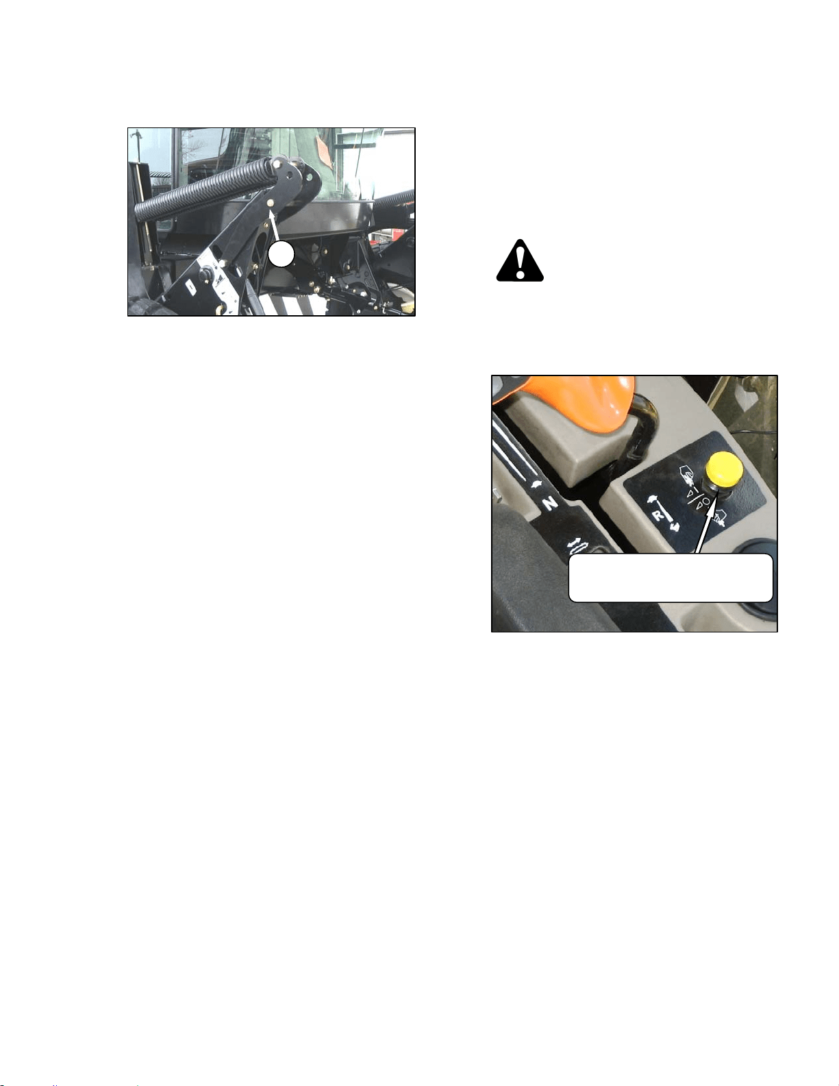
HEADER OPERATION
169304 73 Rev. C
f. If additional levelling is required, install the
removed shim on the opposite linkage.
g. Once header is level, return float pins to their
engaged position (F).
NOTE
If required, additional shims are available
from your dealer
NOTE
Float does not require adjustment after
levelling header.
6.4.3 Header Drive
The headers are hydraulically driven and
controlled from the windrower with no
mechanical drive shafts. One hydraulic piston
pump on the windrower provide fluid power to
the knife, and three gear pumps power the
drapers or auger, reel, lift and positioning
systems and optional attachments.
CAUTION
Check to be sure all bystanders have cleared
the area.
Engage the header as follows:
a. Move throttle to adjust engine speed to idle.
b. Engage header by pushing down on the yellow
knob and pulling up on the black ring at the base
of the switch.
c. A slight delay between switch on and operating
speed is normal.
d. Push yellow knob to disengage header drive.
F
HEADER DRIVE
ENGAGE – – Push Center & Pull Up
DISENGAGE – Push Down
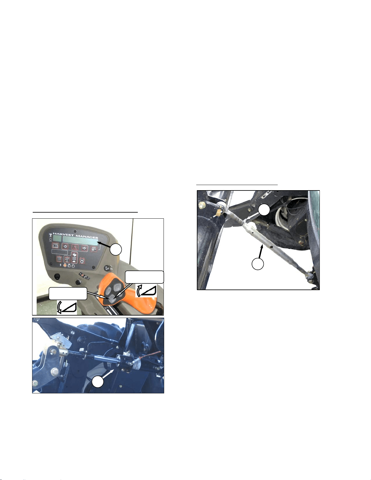
HEADER OPERATION
169304 74 Rev. C
6.4.4 Header Angle
Header angle is defined as the angle between
the ground and the drapers/cutterbar and is
adjustable to accommodate crop conditions
and/or soil type.
Refer to the appropriate operator’s manual for
range of adjustment and recommended settings
for your particular header.
IMPORTANT
Changing header angle will affect flotation
slightly because it has the effect of making
the header lighter or heavier.
IMPORTANT
To prevent excessive guard breakage
when cutting on the ground and when
conditions are not suited to heavier float
(e.g. rocky or wet), do not use the tilt
control on the go. Instead, use the header
height switch.
Change header angle as follows:
HYDRAULIC CENTER LINK (Optional)
a. To decrease (flatten) header angle, operate
HEADER TILT UP switch on GSL handle so that
cylinder (A) retracts. The CDM display will show
a reading on the lower line (B) of decreasing
value between 00.0 and 10.0.
b. To increase (steepen) header angle, operate
HEADER TILT DOWN switch on GSL handle so
that cylinder (A) extends. The CDM display will
show a reading on the lower line of increasing
value between 00.0 and 10.0.
c. The header tilt switch can be deactivated to
prevent inadvertent header angle changes when
pressing the header height control switches.
1. To deactivate, press and hold PROGRAM
switch and momentarily press either
HEADER TILT UP or HEADER TILT
DOWN.
NOTE
If either of the header tilt switches are
pressed while deactivated, the lower
display line will indicate “TILT DISABLED”
for five seconds along with a tone.
2. To reactivate, repeat above procedure.
MECHANICAL CENTER LINK
a. Loosen plate nut (C).
b. To increase (steepen) angle, rotate barrel (D) to
lengthen center link.
c. To decrease (flatten) angle, rotate barrel (D) to
shorten center link.
d. Tighten plate nut (C) with a slight tap of a
hammer.
D
C
HEADER
TILT UP
HEADER
TILT DOWN
B
A
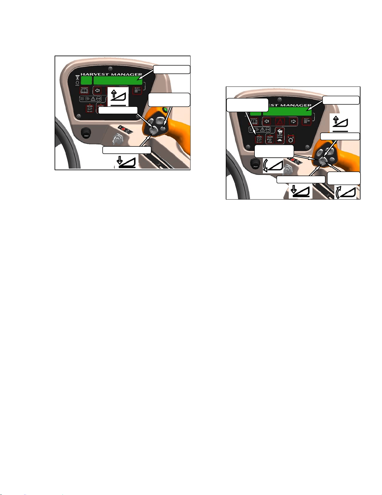
HEADER OPERATION
169304 75 Rev. C
6.4.5 Cutting Height
The header is raised or lowered with the
HEADER UP or HEADER DOWN switches on
the GSL. See illustration. The CDM indicates
the header height by a reading on the DISPLAY
lower line between 00.0 and 10.0, with 00.0
being on the ground. Use DISPLAY
SELECTOR switch to display the current setting.
6.4.5.1 Return To Cut (Optional)
The monitoring system assists the operator in
maintaining the desired cutting height with the
RETURN TO CUT feature that can be turned off
or on with a switch on the CDM.
The RETURN TO CUT feature enables the
operator to have the header return to a pre-
selected cutting height and angle. If desired, the
CDM can be programmed so that only the
cutting height feature is active. The unit is pre-
programmed to activate both cutting height and
header angle.
a. Program the RETURN TO CUT feature as
follows:
IMPORTANT
The windrower must be running with the
header engaged.
1. RETURN TO CUT switch must be off
(indicator light is off).
2. Adjust the header to the desired height with
the HEADER UP or HEADER DOWN
switches on the GSL. CDM displays
between 00.0 and 10.0.
3. Adjust the header angle with the HEADER
TILT UP or HEADER TILT DOWN switches
on the GSL. CDM displays between .0 and
10.0. This step is not required if height only
has been pre-selected.
4. Press the RETURN TO CUT switch on the
CDM. The indicator light will illuminate and
the settings are now programmed into the
WCM.
b. Use the RETURN TO CUT feature as follows:
IMPORTANT
Ensure the header is engaged and the
RETURN TO CUT switch is illuminated.
NOTE
The header can be raised or lowered at
any time by depressing and holding the
HEADER UP or HEADER DOWN
switches on the GSL.
1. If header is above the pre-set height,
momentarily press HEADER DOWN
switch and header will return to pre-set
height.
(continued next page)
DISPLAY
SELECTOR
DISPLAY
HEADER UP
HEADER DOWN
HEADER DOWN
DISPLAY
HEADER UP
HEADER
TILT DOWN
HEADER
TILT UP
RETURN TO
CUT
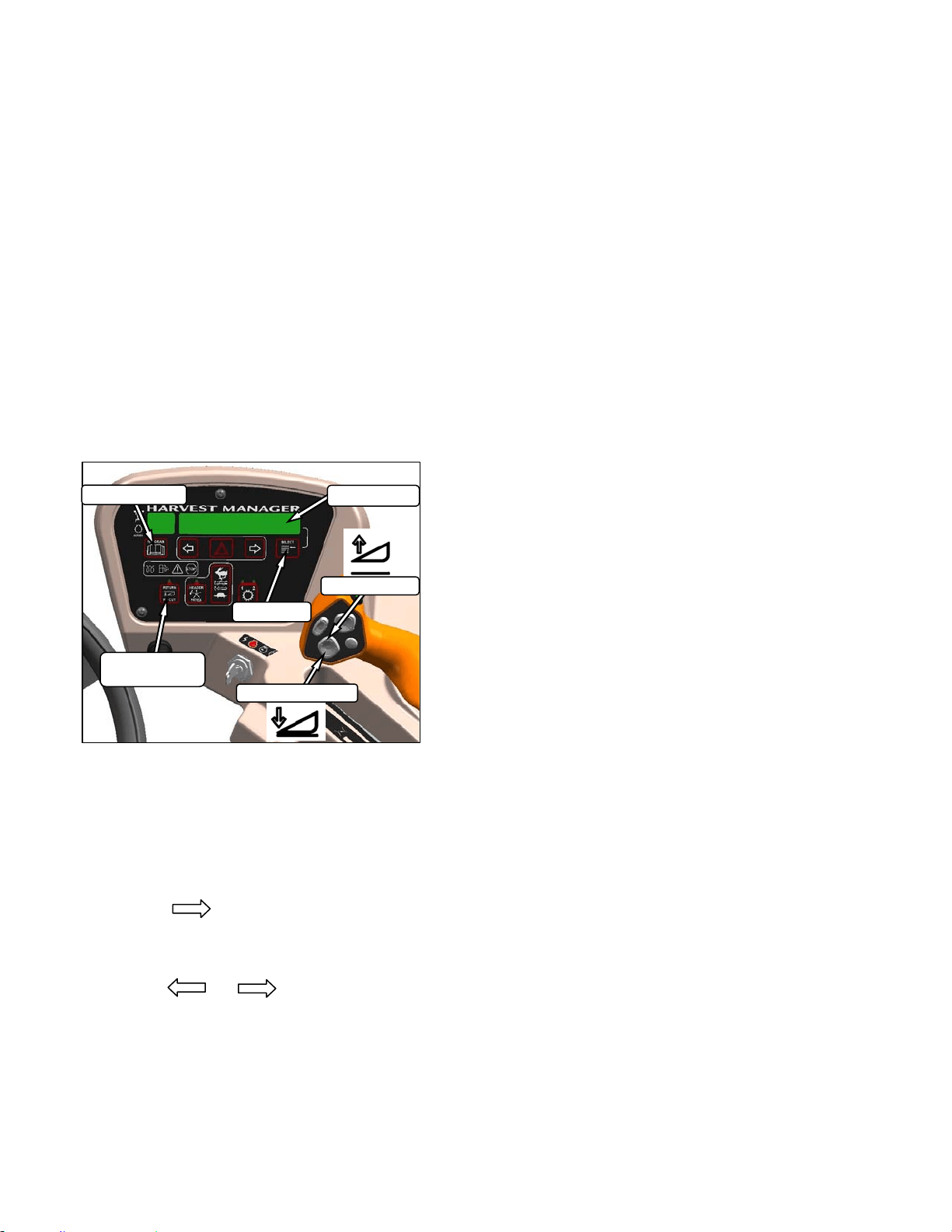
HEADER OPERATION
169304 76 Rev. C
2. If the header is below the pre-set height,
press and hold the HEADER UP switch to
raise the header. Release switch to stop
header. Alarm will sound when header rises
past the pre-set height.
3. If the header angle is changed, double click
(two clicks within 0.5 seconds) the HEADER
TILT UP or HEADER TILT DOWN switch
and the header will return to the pre-set
angle.
NOTE
If the header cannot return to the pre-set
height or angle within 30 seconds, the
RETURN TO CUT feature will deactivate
to prevent the hydraulic oil from
overheating. Push the RETURN TO CUT
switch to reactivate.
6.4.5.2 Auto-Raise Height
a. Program the AUTO RAISE HEIGHT feature as
follows:
1. RETURN TO CUT switch can be off or on.
2. PROGRAM and SELECT on CDM to enter
programming mode.
3. Press SELECT. TRACTOR SETUP? is
displayed on upper line.
4. Press , then SELECT. SET KNIFE
SPEED? is displayed.
5. Press SELECT until AUTO RAISE HEIGHT
is displayed.
6. Press or to change value on
lower line. Range is 0.0 to 10.0 where 10.0
is fully raised.
7. Press PROGRAM to exit programming
mode when finished entering desired values.
b. Use the AUTO RAISE HEIGHT feature as
follows:
IMPORTANT
The windrower must be running with the
header engaged at the cutting height and
the RETURN TO CUT switch activated.
1. Double click HEADER UP switch on the
GSL to raise the header to the AUTO RAISE
HEIGHT set point.
NOTE
If HEADER UP is pressed while header is
being raised, AUTO RAISE HEIGHT is
temporarily disabled and header will
maintain current height.
2. Momentarily press the HEADER DOWN
switch on the GSL to return the header to
the pre-set cutting height.
HEADER DOWN
DISPLAY
HEADER UP
PROGRAM
SELECT
RETURN TO
CUT
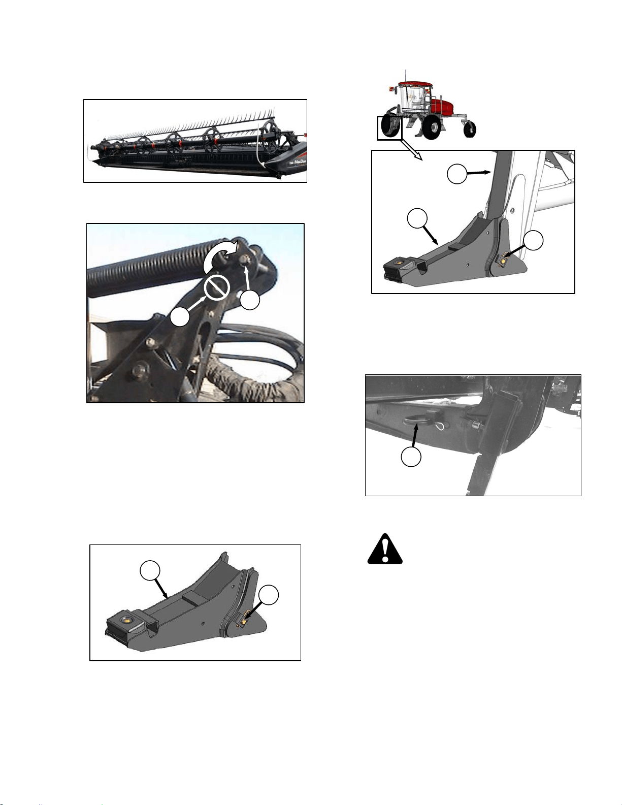
HEADER OPERATION – D SERIES
169304 77 Rev. C
6.5 D SERIES HEADER OPERATION
6.5.1 Header Attachments
IMPORTANT
To prevent damage to the lift system when
lowering header lift linkages without a
header or weight box attached to
windrower, ensure that float engagement
pin is installed in storage location (A), and
not installed at hole location (B).
a. If not installed, attach draper header boots
(supplied with header) to windrower lift linkage
as follows:
1. Remove hairpin and remove pin (C) from
boot (D).
2. Locate boot (D) on lift linkage (E) and
reinstall pin (C). Pin may be installed from
either side of boot.
3. Secure pin (A) with hairpin.
4. Repeat for opposite side.
b. Remove hairpin on pins (F) and remove pins
from header legs.
CAUTION
Check to be sure all bystanders have cleared
the area.
(continued next page)
C
D
D
E
C
F
B
A
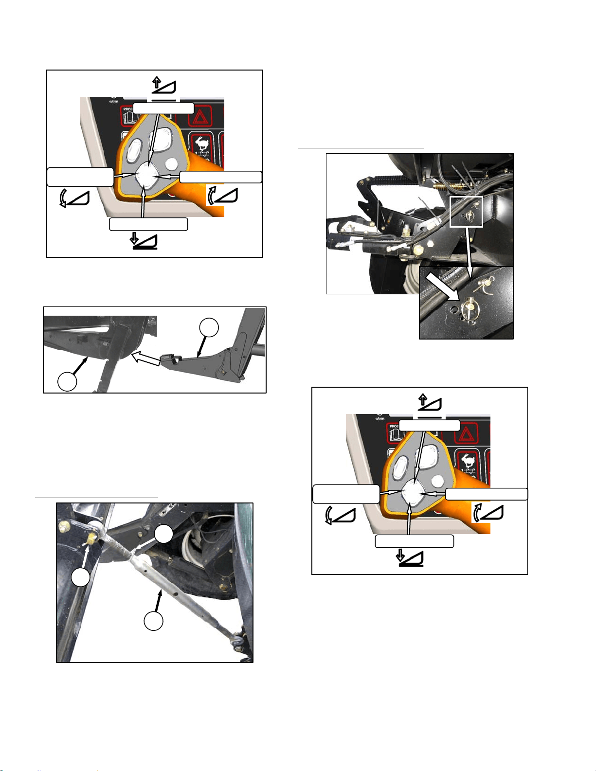
HEADER OPERATION – D SERIES
169304 78 Rev. C
c. 99Start the engine and activate header down
button on the GSL to fully retract header lift
cylinders.
d. Slowly drive windrower forward so that boots (D)
enter header legs (G). Continue to drive slowly
forward until lift linkages contact support plates
in the header legs, and header nudges forward.
e. Check that linkages are properly engaged in
header legs, contacting support plates.
Connect center link as follows:
MECHANICAL LINK – M150
1. Loosen nut (H) and rotate barrel (J) to adjust
length so that link lines up with header
bracket.
2. Install pin (K) and secure with cotter pin.
3. Adjust link to required length for proper
header angle by rotating barrel (J). Tighten
nut (H) against barrel. A slight tap with a
hammer is sufficient.
4. Proceed to step g.
HYDRAULIC LINK - OPTION
1. Re-locate the pin at the frame linkage as
required to position the hook over the
header pin.
2. Activate header tilt cylinder switches on GSL
to extend or retract center link cylinder so
that the hook lines up with the header
attachment pin.
(continued next page)
K
J
H
D
G
HEADER UP
HEADER TILT UP
HEADER DOWN
HEADER
TILT DOWN
HEADER UP
HEADER TILT UP
HEADER DOWN
HEADER
TILT DOWN
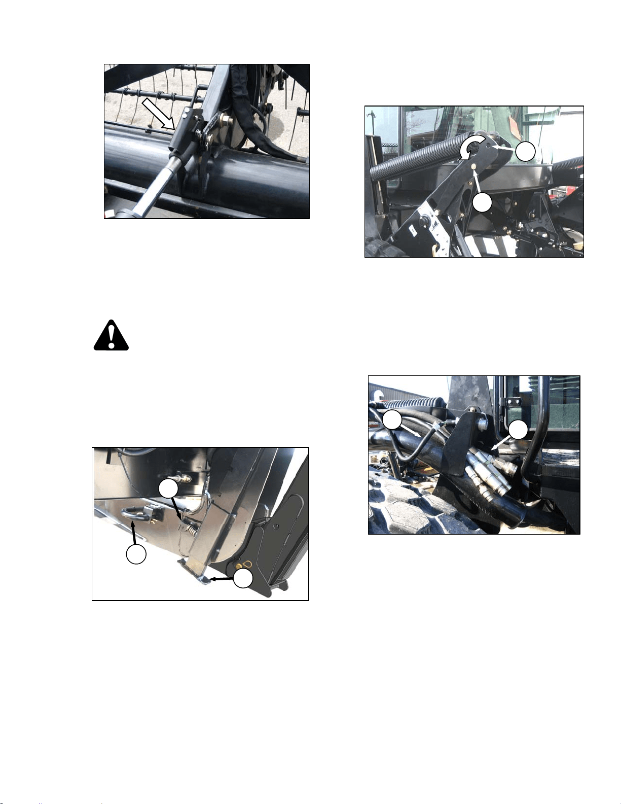
HEADER OPERATION – D SERIES
169304 79 Rev. C
3. Push down on rod end of link cylinder (K)
until hook engages pin on header and is
locked.
4. Check that center link is locked onto header
by pulling upward on rod end of cylinder.
g. Raise the header fully with the header up switch
on the GSL. Stop engine and remove key.
DANGER
To avoid bodily injury from fall of raised
header, always engage header lift cylinder
stops when working on or around raised
header.
h. Engage lift cylinder stops on both lift cylinders.
Refer to Section 6.4.1 Header Lift Cylinder
Stops.
i. Install pin (F) through header leg, (engaging U-
bracket in lift linkage) on both sides and secure
with hairpin.
NOTE
Install hairpin with open end facing aft.
j. Raise header stand (L) to storage position by
pulling pin (M) and lifting stand into uppermost
position. Release pin (M).
k. Remove pin from storage position (N) in linkage
and insert in hole (O) to engage float springs.
Secure with hairpin.
l. Disengage lift cylinder stops. Refer to Section
6.4.1 Header Lift Cylinder Stops.
m. Start engine and activate header lift cylinders
(switch on GSL) to lower header fully.
n. Stop engine and remove key.
o. Connect header drive hoses (P) and electrical
harness (Q) to header. Refer to the Draper
Header Operator’s Manual.
(continued next page)
HEADER DRIVE HOSES
Q
P
N
O
L
M
F
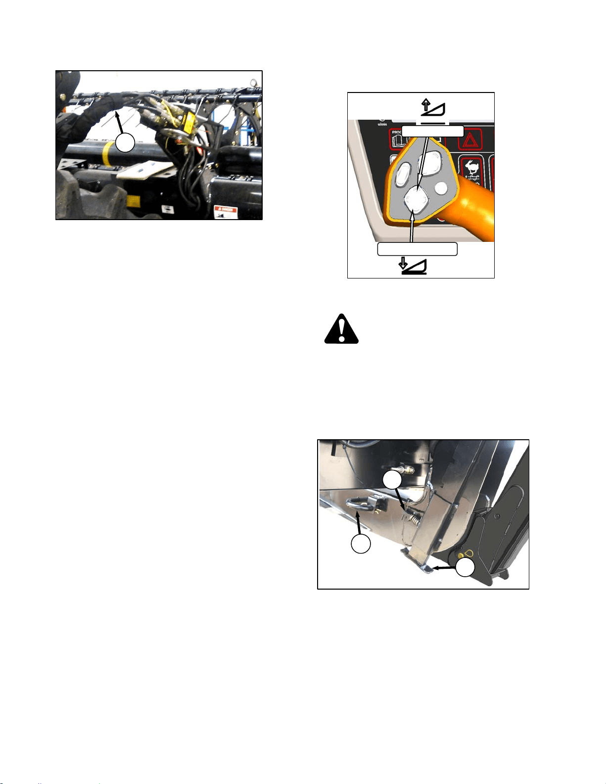
HEADER OPERATION – D SERIES
169304 80 Rev. C
p. Connect reel hydraulics (R) at RH side of
windrower. Refer to the Draper Header
Operator’s Manual.
6.5.2 Header Detachment
a. Raise the header fully with the header up switch
on the GSL. Stop engine and remove key.
DANGER
To avoid bodily injury from fall of raised
header, always engage header lift cylinder
stops when working on or around raised
header.
b. Engage lift cylinder stops on both lift cylinders.
Refer to Section 6.4.1 Header Lift Cylinder
Stops.
c. Remove pin (A) from header leg on both sides.
d. Lower header stand (B) by pulling spring loaded
pin (C). Release pin to lock stand.
(continued next page)
B
C
A
HEADER UP
HEADER DOWN
REEL HYDRAULICS
R

HEADER OPERATION – D SERIES
169304 81 Rev. C
e. Remove pin from location (D) to disengage float
springs, and insert in storage hole (E). Secure
with lynch pin.
IMPORTANT
To prevent damage to the lift system when
lowering header lift linkages without a
header or weight box attached to
windrower, ensure that float engagement
pin is installed in storage location (E), and
not installed at hole location (D).
f. Disengage lift cylinder stops.
g. Start engine, choose a level area and lower
header to the ground. Stop engine and remove
key.
h. Disconnect header drive hydraulics (F) and
electrical harness (G) from header. Refer to the
Draper Header Operator’s Manual.
i. Disconnect reel hydraulics (H) and store on
bracket at windrower LH side.
j. Disconnect center link as follows:
MECHANICAL LINK – M150
1. Loosen nut (J) and rotate barrel (K) to
relieve load on link.
2. Remove cotter pin on pin (L), and remove
pin to disconnect from windrower. Re-install
pin in header.
3. Tighten nut (J) against barrel. A slight tap
with a hammer is sufficient.
(continued next page)
D
E
REEL HYDRAULICS
H
L
K
J
HEADER DRIVE HOSES
G
F
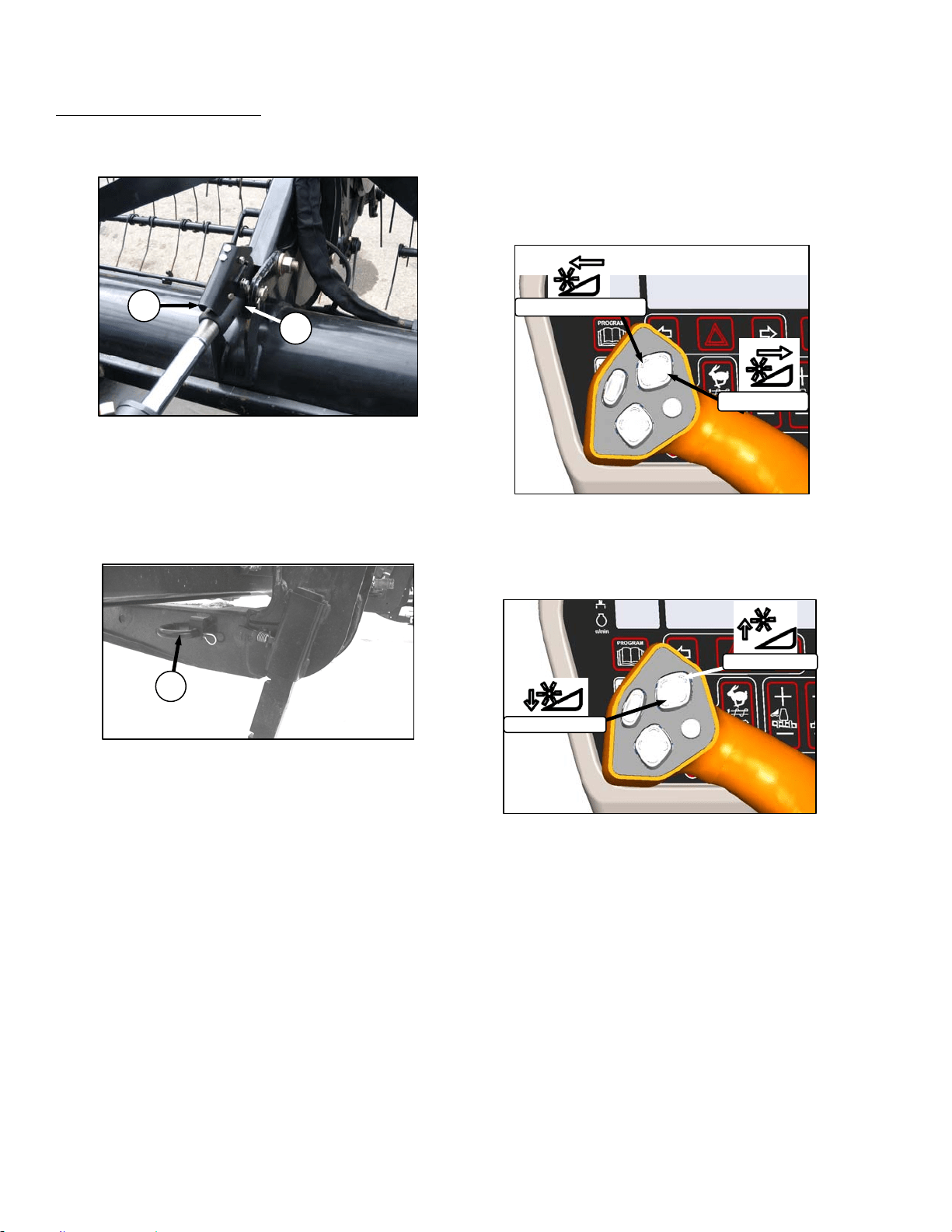
HEADER OPERATION – D SERIES
169304 82 Rev. C
HYDRAULIC LINK – OPTION
1. Start engine and activate header tilt cylinder
switch on GSL to release load on center link
cylinder.
2. Disconnect center link by lifting release (M)
and lift hook (N) off header.
k. Slowly back windrower away from header.
NOTE
If hay conditioner is installed, watch
clearances on both sides.
l. Reinstall pin (A) into header leg and secure with
hairpin.
6.5.3 Header Position Adjustments
Refer to Section 6.4 HEADER OPERATION for
procedures for controlling header height, header
tilt, and float.
6.5.4 Reel Fore-Aft Position (Optional)
Press and hold the switch for the desired fore or
aft movement of the reel.
6.5.5 Reel Height
Press and hold the switch for the desired up or
down movement of the reel.
A
M
N
REEL AFT
REEL FORWARD
REEL UP
REEL DOWN
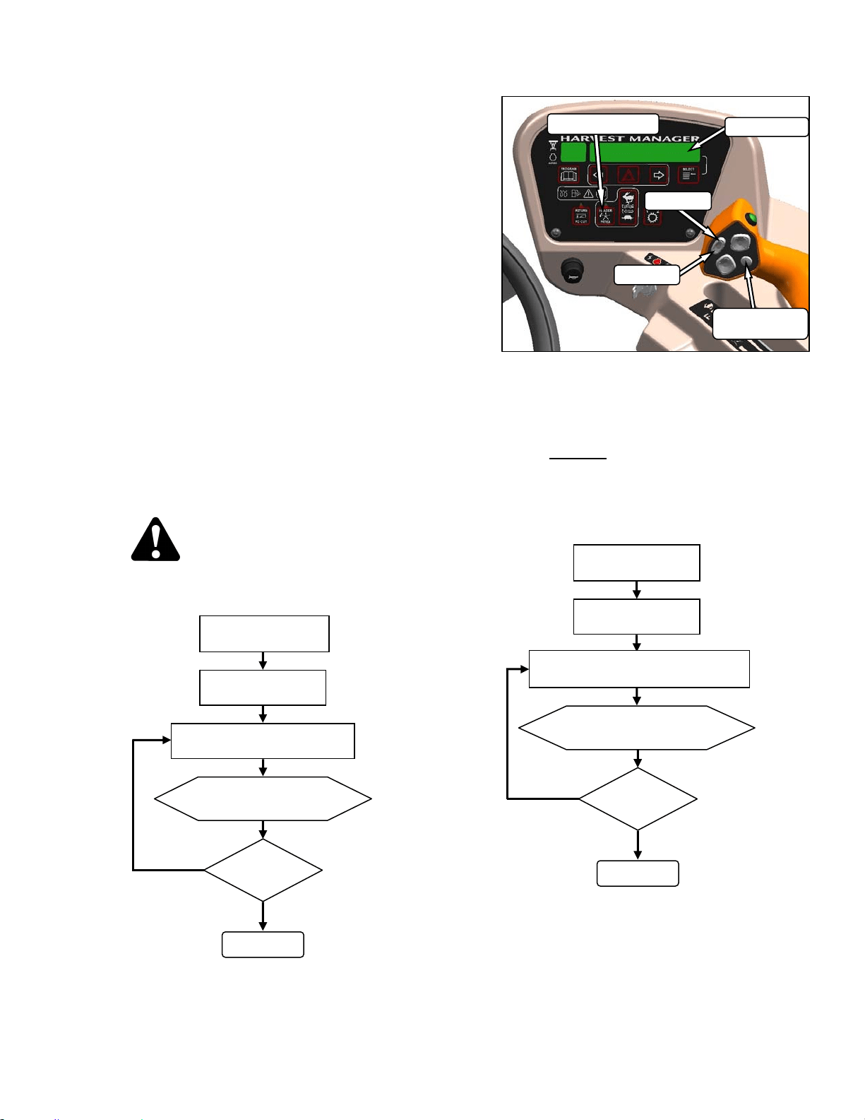
HEADER OPERATION – D SERIES
169304 83 Rev. C
6.5.6 Reel Speed
Reel speed is controlled with switches on the
CDM in the cab. On D Series draper headers, it
can be set relative to the ground speed of the
windrower using the Header Index feature, or
can run independently. Refer to the Operator’s
Manual for your specific header for windrowing
guidelines and recommended speeds.
6.5.6.1 Reel to Ground Speed – Index (Option)
Setting the speed of the reel relative to ground
speed using the Header Index function allows
the operator to maintain a preset reel to ground
speed, while operating at varying ground
speeds. This feature requires that an
“expansion module” has been installed, either at
the factory or at your dealer. To use this
feature, set the Minimum Reel Speed, and set
the Reel Index as follows:
a. Set Reel Minimum Speed
IMPORTANT
Windrower can be moving but must be
less than minimum reel speed.
CAUTION
Check to be sure all bystanders have cleared
the area.
NOTE
DISPLAY will flash ##.## MIN REEL
(MPH or KPH) to prompt the operator to
change the minimum set point or increase
ground speed if Ground Speed Plus Index
is less than
the Minimum Reel Speed Set
Point.
b. Set Reel Index while driving windrower at
normal operating speed and greater than
minimum reel speed.
NOTE
See example on following page.
(continued next page)
##.## = MPH or KPH
ENGAGE HEADER
HEADER INDEX
SWITCH - ON
ON GSL PRESS REEL SPEED
SWITCH FAST OR SLOW
DISPLAY SHOWS
##. ## MIN REEL
DONE
SPEED
O.K.?
NO
YES
##.## = MPH or KPH
##.# = 0.0 to 9.9
ENGAGE HEADER
HEADER INDEX
SWITCH - ON
ON GSL PRESS REEL SPEED
SWITCH FAST OR SLOW
DISPLAY SHOWS
##.## ##.# REEL IND
DONE
INDEX
O.K.?
NO
YES
DISPLAY
SELECTOR
DISPLAY
HEADER INDEX
FAST
SLOW
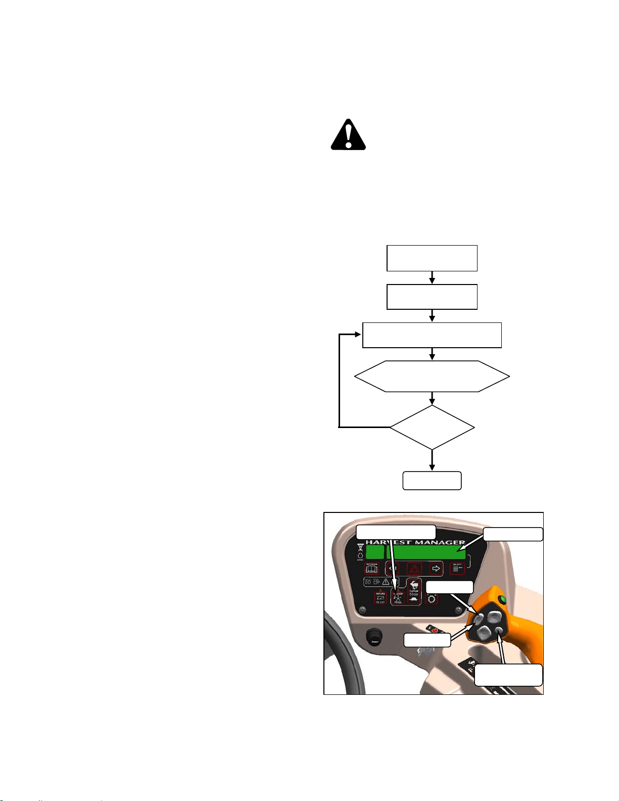
HEADER OPERATION – D SERIES
169304 84 Rev. C
Example:
Windrower is operating at 8 mph with Header
Index on and set at 5.5. Display shows;
13.5 5.5 REEL IND
where 13.5 (8+5.5) is the reel speed in mph, and
5.5 is the header index setting.
Windrower speed drops to 7.5 mph at same
Header Index setting. Display shows;
13.0 5.5 REEL IND
where 13.0 (7.5+5.5) is the reel speed in mph,
and 5.5 is the header index setting.
Windrower is operating at 8 mph with Header
Index on and set at 1.0. Display shows;
9.0 1.0 REEL IND
where 9.0 (8+1.0) is the reel speed in mph, and
1.0 is the header index setting.
6.5.6.2 Reel Only Speed
Set the reel speed independently of ground
speed as follows:
CAUTION
Check to be sure all bystanders have cleared
the area.
NOTE
This procedure can also be used to
change the draper speed “on the go”.
These changes become the new set-
points.
##.## = MPH or KPH
ENGAGE HEADER
HEADER INDEX
SWITCH - OFF
ON GSL PRESS REEL SPEED
SWITCH FAST OR SLOW
DISPLAY SHOWS
##.## REEL MPH
DONE
SPEED
O.K.?
NO
YES
DISPLAY
SELECTOR
DISPLAY
HEADER INDEX
FAST
SLOW
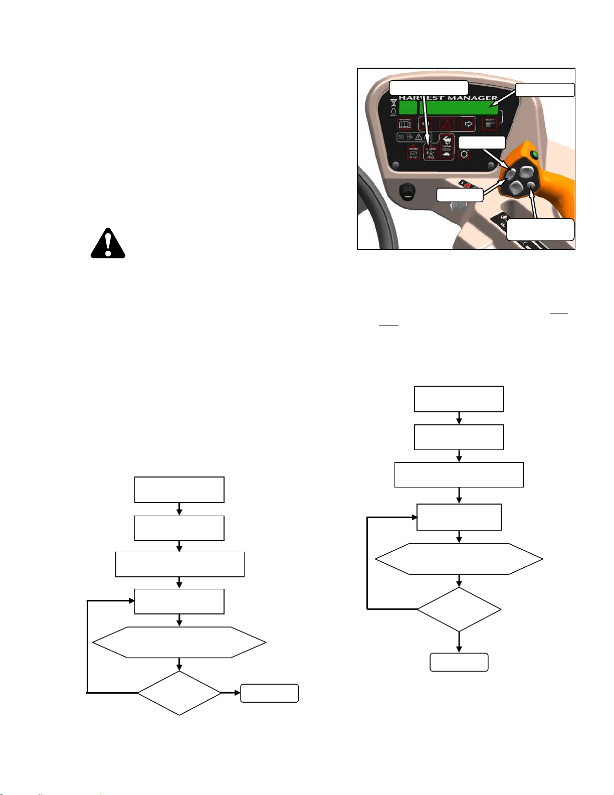
HEADER OPERATION – D SERIES
169304 85 Rev. C
6.5.7 Draper Speed
Draper speed affects the orientation of stalks in
the windrow. Faster draper speeds tend to form
herringbone or dovetail configurations. Refer to
your header operator’s manual for guidelines on
what speed to use.
The draper speed can be set with switches on
the CDM relative to the ground speed of the
windrower with the Header Index function, or
can run independently. This feature requires
that an “expansion module” has been installed,
either at the factory or at your dealer.
CAUTION
Check to be sure all bystanders have cleared
the area.
6.5.7.1 Draper To Ground Speed – Index
(Optional)
To use this feature, set the Draper Minimum
Speed, and set the Draper Index.
NOTE
Reducing engine speed saves fuel and
reduces noise in the cab. Ground/cutting
speed can be maintained using this
feature.
a. Set Draper Minimum Speed:
IMPORTANT
Windrower can be moving but must be
less than minimum reel speed.
NOTE
DISPLAY will flash ##.# MIN CONV (MPH
or KPH) to prompt the operator to change
the minimum set point or increase ground
speed if Ground Speed Plus Index is less
than the Minimum Draper Speed Set
Point.
b. Set Draper Index while driving windrower at
normal operating speed and greater than
minimum draper speed.
NOTE
See example on following page.
(continued next page)
##.# = MPH or KPH
ENGAGE HEADER
ON CDM PRESS
FAST OR SLOW
DISPLAY SHOWS
##.# DRAPER MIN
DONE
SPEED
O.K.?
NO
YES
PRESS DISPLAY SELECTOR
FOR DRAPER MIN
HEADER INDEX
SWITCH - ON
##.## = MPH or KPH
##.# = +5.0 to -5.0
ENGAGE HEADER
HEADER INDEX
SWITCH - ON
ON CDM PRESS
FAST OR SLOW
DISPLAY SHOWS
##.## ##.# DRAP IND
DONE
INDEX
O.K.?
NO
YES
PRESS DISPLAY SELECTOR
FOR DRAPER INDX
DISPLAY
SELECTOR
DISPLAY
HEADER INDEX
FAST
SLOW
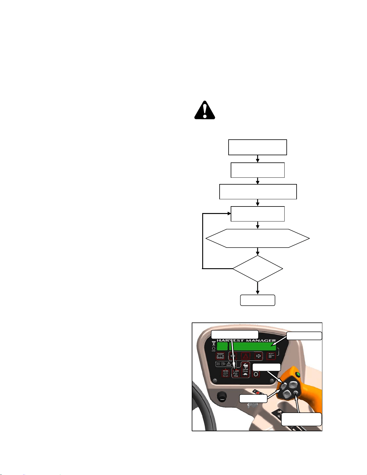
HEADER OPERATION – D SERIES
169304 86 Rev. C
Example:
Windrower is operating at 8 mph with Header
Index on and set at 1.5. Display shows;
9.5 1.5 DRAP INDX
where 9.5 (8+1.5) is the draper speed in mph,
and 1.5 is the header index setting.
Windrower speed drops to 7.5 mph at same
Header Index setting. Display shows;
9.0 1.5 DRAP INDX
where 9.0 (7.5+1.5) is the draper speed in mph,
and 1.5 is the header index setting.
Windrower is operating at 8 mph with Header
Index on and set at 0.9. Display shows;
8.9 0.9 DRAP INDX
where 8.9 (8+0.9) is the draper speed in mph,
and 0.9 is the header index setting.
6.5.7.2 Draper Speed Independent of Ground
Speed
Set the speed of the draper independently of
ground speed as follows:
NOTE
This procedure can also be used to
change the draper speed “on the go”.
CAUTION
Check to be sure all bystanders have cleared
the area.
##.# = MPH or KPH
HEADER ENGAGED
ON CDM PRESS
FAST OR SLOW
DISPLAY SHOWS
##.# DRAPER SPEED
DONE
SPEED
O.K.?
NO
YES
PRESS DISPLAY SELECTOR
FOR DRAPER SPHEADER
HEADER INDEX
SWITCH - OFF
DISPLAY
SELECTOR
DISPLAY
HEADER INDEX
FAST
SLOW
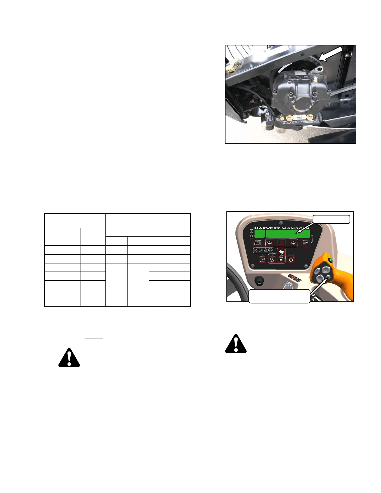
HEADER OPERATION – D SERIES
169304 87 Rev. C
6.5.8 Knife Speed
The ideal cutting speed of the knife should be
such that a clean cut is achieved. Crop types
and conditions usually influence the knife and
forward speeds. Refer to the header operator’s
manual for more information on knife speeds.
The knife speed is manually set by making
adjustments to the knife drive pump and has
been pre-set at the factory. For optimum
performance, adjust the knife speed according
to the header being used. See the following
table.
If the machine is equipped with the appropriate
sensor and optional module, the CDM will notify
the operator when the knife speed reaches an
overload pre-set (usually 75% of knife speed).
The pre-set can be changed on the CDM. Refer
to Section 5.18.5 CDM Programming.
NOTE
The knife speed should stay within the
range specified for each header.
HEADER
DESCRIPTION
KNIFE SPEED
TYPE SIZE MINIMUM MAXIMUM
RPM SPM RPM SPM
Draper DK 15 750 1500 950 1900
Draper DK 20 & 25 700 1400 850 1700
Draper DK 30
600 1200
800 1600
Draper DK 35 700 1400
Draper SK 20 & 25 750 1500
Draper SK 30
700 1400
Draper SK 35 550 1100
RPM = speed of wobble box pulley.
SPM = strokes per minute of knife (RPM x 2).
a. Determine the knife speed as follows if the
machine is not
equipped with the optional
module:
CAUTION
Check to be sure all bystanders have cleared
the area.
1. Run engine at 2600 rpm with the header
drive engaged and with ISC off.
2. Check wobble box pulley speed with a hand-
held tachometer.
3. Multiply the rpm reading by two for the knife
speed in strokes per minute.
b. Determine the knife speed as follows if the
machine is
equipped with the optional module:
1. Run engine at 2600 rpm with the header
drive engaged and ISC off.
2. Press SELECTOR button on the GSL until
the CDM displays the knife speed in SPM.
c. If required, adjust knife speed as follows:
DANGER
Stop engine and remove key from ignition
before leaving operator's seat for any
reason. A child or even a pet could engage
an idling machine.
1. Shutdown engine.
(continued next page)
DISPLAY
DISPLAY SELECTOR
FOR UPPER LINE
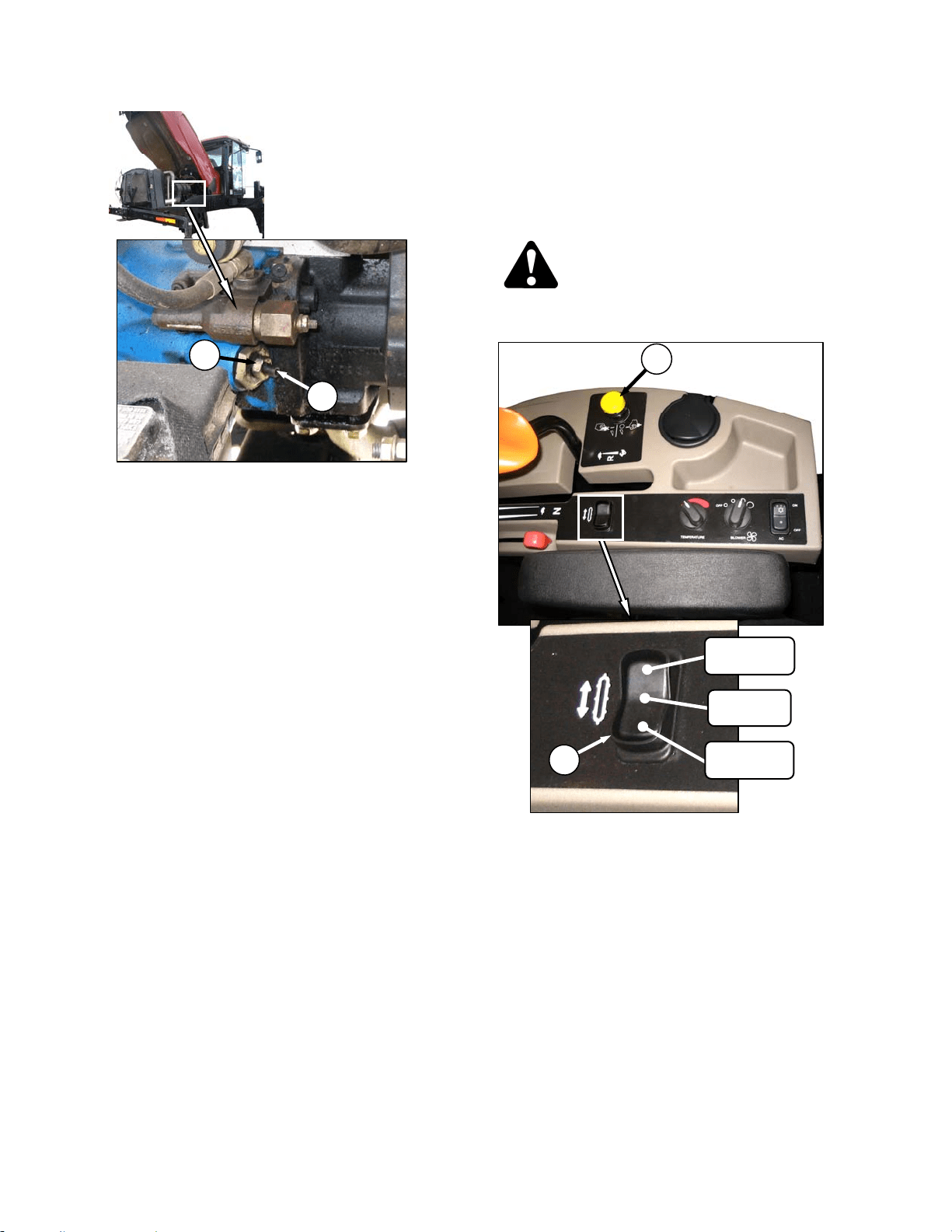
HEADER OPERATION – D SERIES
169304 88 Rev. C
2. Loosen jam-nut (A).
3. Turn adjuster screw (B) clockwise (screw in)
to decrease knife speed, and counter-
clockwise (screw out) to increase the knife
speed.
NOTE
One turn of the adjuster screw will change
the knife speed by approximately 116
strokes per minute, or the wobble box
pulley speed by 58 revolutions per minute.
4. Once adjustment has been made re-torque
jam nut (A) as shown.
d. Start engine and recheck knife speed.
6.5.9 Deck Shift (Optional)
The hydraulic deck shift option allows the
operator to control deck position and draper
rotation from the operator’s station. It enables
crop delivery from left side, center, or right side
of the header. Shift decks as follows:
CAUTION
Check to be sure all bystanders have cleared
the area.
a. Engage header by pushing down on the yellow
knob and pulling up on the black ring at the base
of the switch (A).
b. Push rocker switch (B) to desired delivery
position. Deck(s) will move, and direction of
drapers will change accordingly.
c. Operate windrower.
A
B
CENTER
DELIVERY
RIGHT SIDE
DELIVERY
LEFT SIDE
DELIVERY
A
B
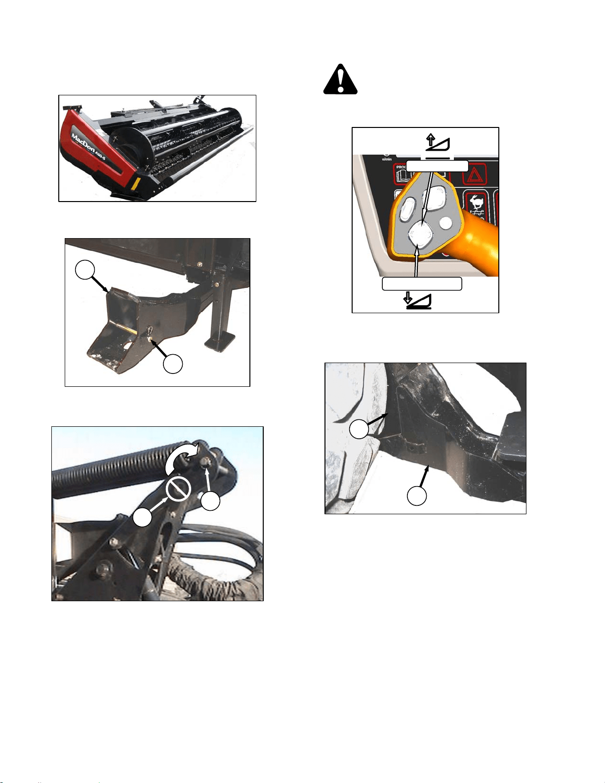
HEADER OPERATION – A SERIES
169304 89 Rev. C
6.6 A SERIES HEADER OPERATION
6.6.1 Header Attachment – A Series
a. Remove hairpin from pin (A), and remove pin
from left and right header boots (B) on header.
IMPORTANT
To prevent damage to the lift system when
lowering header lift linkages without a
header or weight box attached to
windrower, ensure that float engagement
pin is installed in storage location (C), and
not installed at hole location (D).
CAUTION
Check to be sure all bystanders have cleared
the area.
b. Start the engine and activate HEADER DOWN
button on the GSL to fully retract header lift
cylinders.
c. Slowly drive windrower forward so that feet (E)
on windrower enter boots (B) on the header.
Continue to drive slowly forward until feet
engage the boots, and header nudges forward.
(continued next page)
D
C
B
A
E
B
HEADER UP
HEADER DOWN
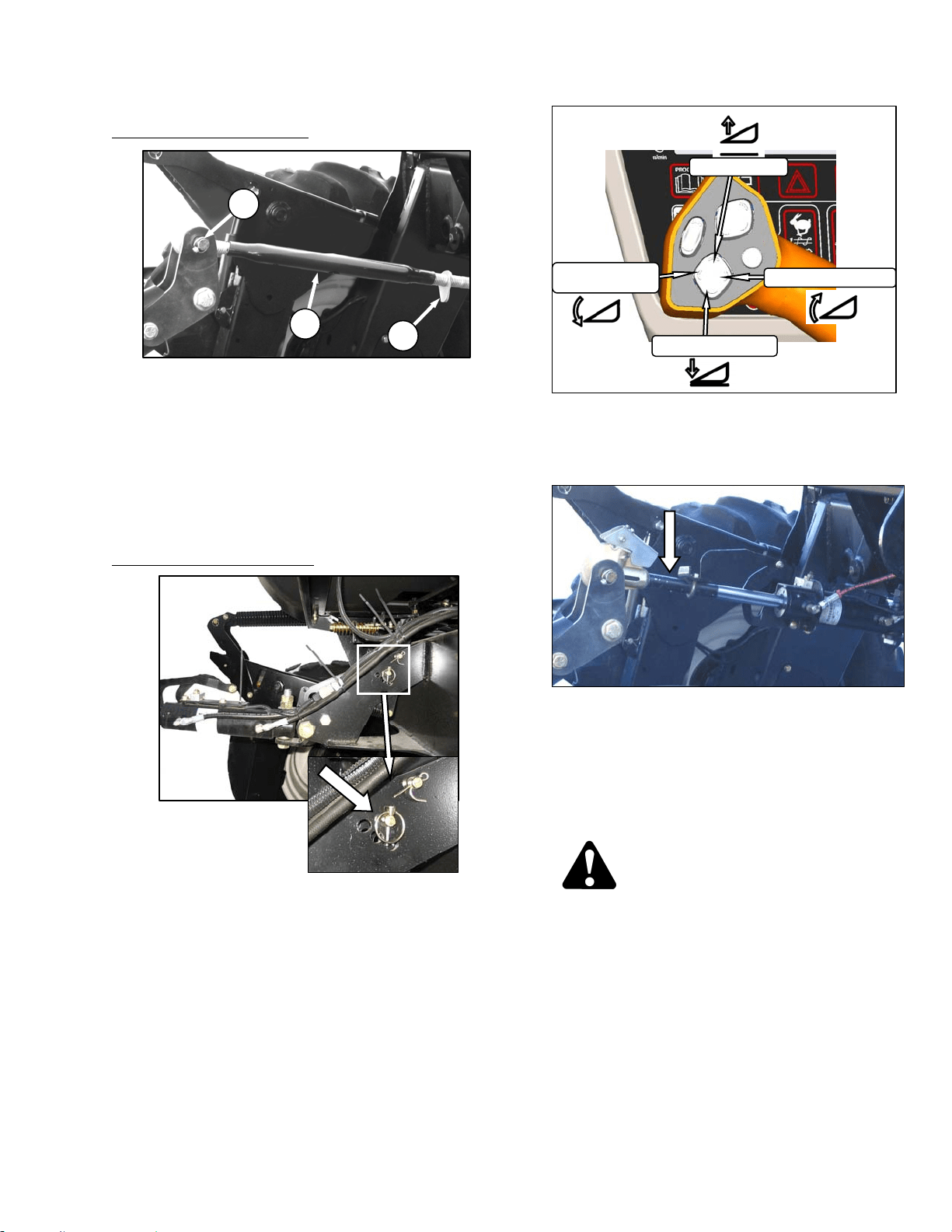
HEADER OPERATION – A SERIES
169304 90 Rev. C
d. Connect center link as follows:
MECHANICAL LINK – M150
1. Loosen nut (F) and rotate barrel (G) to
adjust length so that other end lines up with
header bracket.
2. Install pin (H) and secure with cotter pins.
3. Adjust link to required length for proper
header angle by rotating barrel (G). Tighten
nut (F) against barrel. A slight tap with a
hammer is sufficient.
4. Proceed to step e.
HYDRAULIC LINK - OPTION
1. Re-locate the pin at the frame linkage as
required to position the hook over the
header pin.
2. Activate HEADER TILT cylinder switches on
GSL to extend or retract center link cylinder
so that the hook lines up with the header
attachment pin.
3. Push down on rod end of link cylinder until
hook engages pin on header and is locked.
4. Check that center link is locked onto header
by pulling upward on rod end of cylinder.
e. Raise the header fully with THE HEADER UP
switch on the GSL. Stop engine and remove
key.
DANGER
To avoid bodily injury from fall of raised
header, always engage header lift cylinder
stops when working on or around raised
header.
f. Engage lift cylinder stops on both lift cylinders.
Refer to Section 6.4.1 Header Lift Cylinder
Stops.
(continued next page)
G
F
H
HEADER UP
HEADER TILT UP
HEADER DOWN
HEADER
TILT DOWN
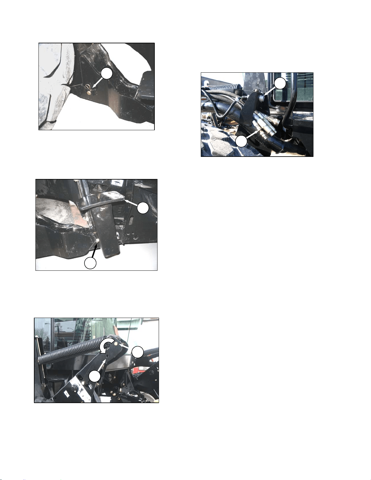
HEADER OPERATION – A SERIES
169304 91 Rev. C
g. Install pin (A) through each boot and foot and
secure with hairpin..
IMPORTANT
Ensure pin (A) is fully inserted and hairpin
is installed behind bracket.
h. Remove lynch pin from pin (J) in stand (K).
i. Hold stand and remove pin (J).
j. Reposition stand to storage position by inverting
stand and re-locating on bracket as shown.
Reinsert pin (J) and secure with lynch pin.
k. Remove pin (L) from storage position in linkage
and insert in hole (M) to engage float springs.
Secure with lynch pin.
l. Disengage lift cylinder stops.
m. Start engine, and activate header lift cylinder
switch on GSL to lower header fully. Stop
engine and remove key.
n. Connect header drive hydraulics (N) and
electrical harness (O) to header. Refer to Auger
Header Operator’s Manual.
J
K
M
L
N
O
A
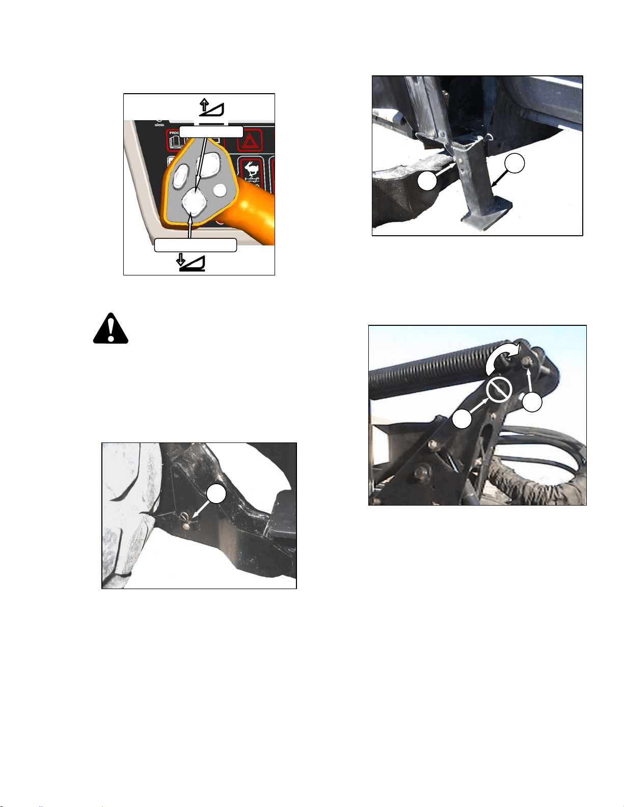
HEADER OPERATION – A SERIES
169304 92 Rev. C
6.6.2 Header Detachment
a. Raise the header fully with the header up switch
on the GSL. Stop engine and remove key.
DANGER
To avoid bodily injury from fall of raised
header, always engage header lift cylinder
stops when working on or around raised
header.
b. Engage lift cylinder stops on both lift cylinders.
Refer to Section 6.4.1 Header Lift Cylinder
Stops.
c. Remove hairpin from pin (A), and remove pin
from left and right header boots on header.
d. Lower stand (C) by pulling pin (D), inverting
stand and re-locating on bracket. Reinsert pin
(D) and secure with hairpin.
e. Remove pin from linkage (E) to disengage float
springs, and insert in storage hole (F). Secure
with lynch pin. Repeat for opposite linkage.
IMPORTANT
To prevent damage to the lift system when
lowering header lift linkages without a
header or weight box attached to
windrower, ensure that float engagement
pin is installed in storage location (F), and
not installed at hole location (E).
f. Disengage lift cylinder stops.
g. Start engine, choose a level area and lower
header to the ground.
(continued next page)
HEADER UP
HEADER DOWN
E
F
A
C
D
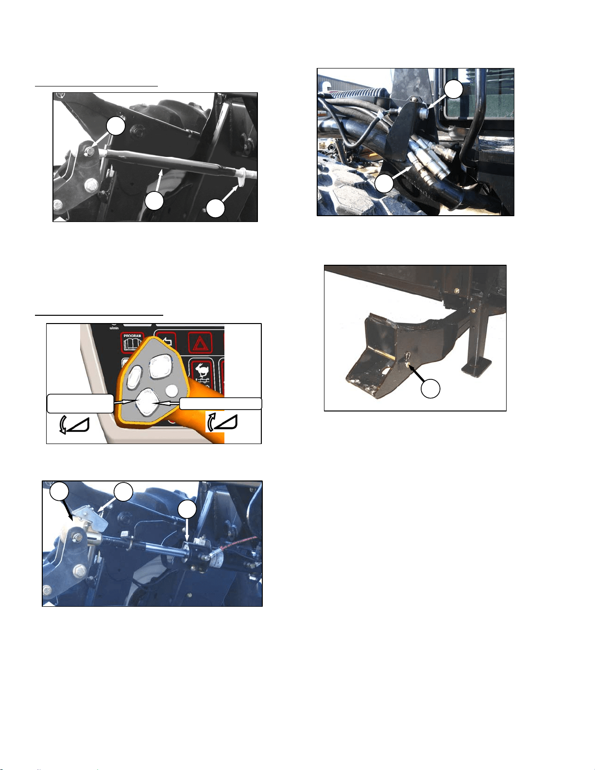
HEADER OPERATION – A SERIES
169304 93 Rev. C
h. Disconnect center link as follows:
MECHANICAL LINK – M150
1. Loosen nut (G) and rotate barrel (H) to
relieve load on link.
2. Remove cotter pin on pin (J), and remove
pin to disconnect from header. Re-install pin
in header.
3. Proceed to step i.
HYDRAULIC LINK – OPTION
1. Activate header tilt cylinder switch on GSL to
release load on center link cylinder (K).
2. Lift hook release (L) and lift hook (M) off
header pin.
i. Disconnect header drive hydraulics (N) and
electrical harness (O). Refer to the Auger
Header Operator’s Manual.
j. Slowly back windrower away from header.
k. Re-install pins (A) in header boots.
K
L
M
H
G
J
N
O
HEADER TILT UP
HEADER
TILT DOWN
A
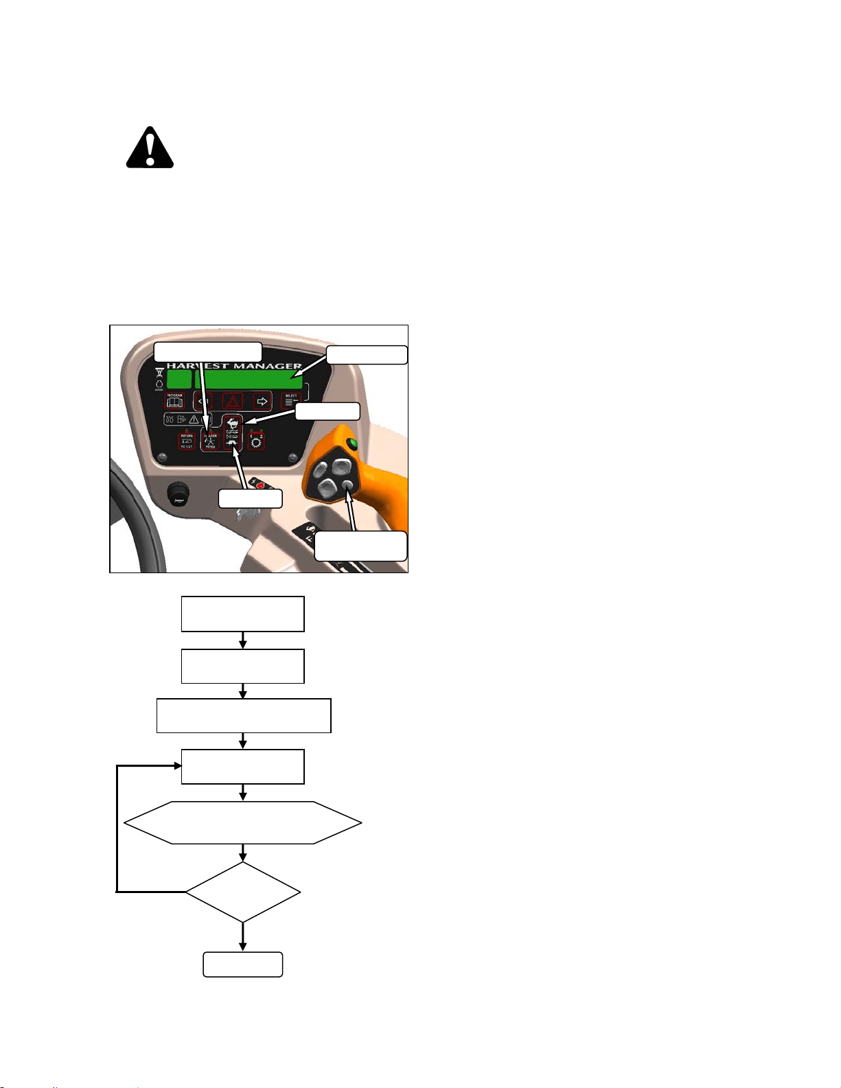
HEADER OPERATION – A SERIES
169304 94 Rev. C
6.6.3 Auger Speed
CAUTION
Check to be sure all bystanders have cleared
the area.
6.6.3.1 A40-D Headers
On A40-D double knife headers, the auger
speed can be changed independently from the
reel speed with a switch on the CDM. Change
auger speed as follows:
6.6.3.2 A30-S and A30-D Headers
On A30 Series auger headers, the auger speed
is fixed to the knife speed.
NOTE
The auger speed can be independently
changed from the knife speed by changing
the drive sprocket. Refer to A30-S, A30-D
& A40-D Self Propelled Windrower
Headers OPERATOR’S MANUAL.
DISPLAY
SELECTOR
DISPLAY
HEADER INDEX
FAST
SLOW
ENGAGE HEADER
ON CDM PRESS
FAST OR SLOW
DISPLAY SHOWS
##.# AUGER SPEED
DONE
SPEED
O.K.?
NO
YES
PRESS DISPLAY SELECTOR
FOR ##.# AUGER SPEED
HEADER INDEX
SWITCH - OFF
##.# = 4.7 – 9.9
4.7 = 150 rpm
* 9.9 = 320 rpm
* Auger Speed Not To Exceed 320 rpm.
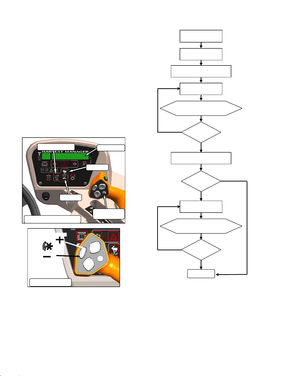
HEADER OPERATION – A SERIES
169304 95 Rev. C
6.6.4 Reel Speed
6.6.4.1 A30-S and A30-D Headers
The reel speed is fixed to the auger speed and
to the knife speed. Both can be changed by
installing alternate drive sprockets. Refer to
your Auger Header Operator’s Manual.
6.6.4.2 A40-D Header
The A40-D auger header features a hydraulic
direct drive reel with operating speed range of
51 to 76 rpm and is controlled with switches on
the CDM, and on the GSL at the operator’s
station. The hydraulic flows for the reel and
auger are interconnected so that the auger and
reel speeds are controlled using a combination
of the CDM switches and the GSL switches.
ENGAGE HEADER
ON CDM PRESS
FAST
DISPLAY SHOWS
##.# AUGER SPEED
DONE
SPEED
99.0?
NO
YES
PRESS DISPLAY SELECTOR
FOR ##.#
A
UGER SPEED
HEADER INDEX
SWITCH - OFF
##.# = 0.00 – 9.9
00.0 = 150 rpm
* 9.9 = 320 rpm
* Auger Speed Not To Exceed 320 rpm.
ON GSL PRESS
FAST OR SLOW
DISPLAY SHOWS
##.## REEL SPEED
SPEED
OK?
NO
YES
PRESS DISPLAY SELECTOR
FOR ##.## REEL SPEED
SPEED
OK?
NO
YES
##.## = RPM
DISPLAY
SELECTOR
DISPLAY
HEADER INDEX
FAST
SLOW
AUGER & REEL SPEED
SLOW
FAST
REEL SPEED

HEADER OPERATION – A SERIES
169304 96 Rev. C
6.6.5 Knife Speed
The ideal cutting speed of the knife should be
such that a clean cut is achieved. Crop types
and conditions usually influence the knife and
forward speeds.
The knife speed is manually set by making
adjustments to the knife drive pump and has
been pre-set at the factory. For optimum
performance, adjust the knife speed according
to the header being used. See the following
table.
If the machine is equipped with the appropriate
sensor and optional module, the CDM will notify
the operator when the knife speed reaches an
overload pre-set (usually 75% of knife speed).
The pre-set can be changed on the CDM. Refer
to Section 5.18.5 CDM Programming
NOTE
The knife speed should stay within the
range specified for each header.
HEADER
DESCRIPTION
KNIFE SPEED
TYPE SIZE MINIMUM MAXIMUM
RPM SPM RPM SPM
Auger
A40D
All
700 1400
950 1900
Auger
A30D
775 1550
Auger
A30S
625 1250 775 1550
RPM = speed of wobble box pulley.
SPM = strokes per minute of knife (RPM x 2).
a. Determine the knife speed as follows if the
machine is not
equipped with the optional
module:
CAUTION
Check to be sure all bystanders have cleared
the area.
1. Run engine at 2600 rpm with the header
drive engaged and with ISC off.
2. Check wobble box pulley speed with a hand-
held tachometer.
3. Multiply the rpm reading by two for the knife
speed in strokes per minute.
b. Determine the knife speed as follows if the
machine is
equipped with the optional module:
1. Run engine at 2600 rpm with the header
drive engaged and ISC off.
2. Press SELECTOR button on the GSL until
the CDM displays the knife speed in SPM.
c. If required, adjust knife speed as follows:
DANGER
Stop engine and remove key from ignition
before leaving operator's seat for any
reason. A child or even a pet could engage
an idling machine.
1. Shutdown engine.
(continued next page)
DISPLAY
DISPLAY SELECTOR
FOR UPPER LINE
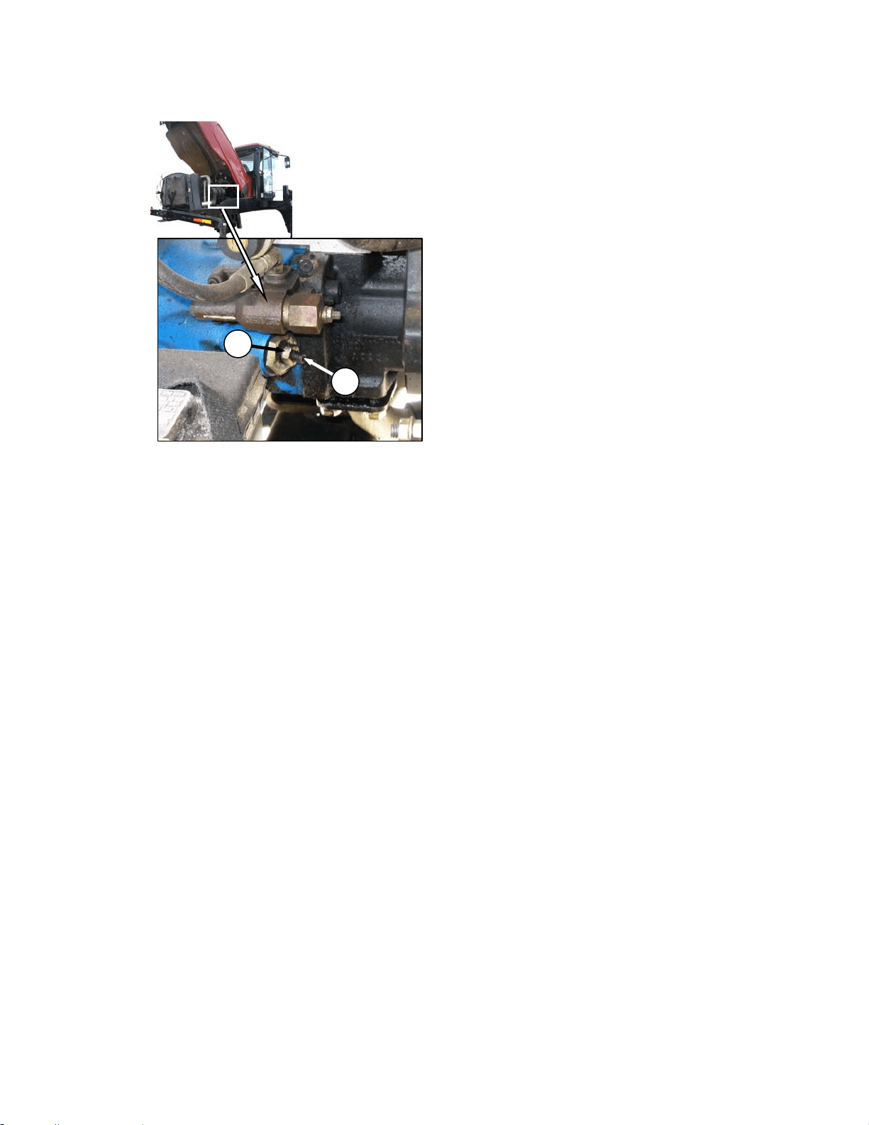
HEADER OPERATION – A SERIES
169304 97 Rev. C
2. Loosen jam-nut (A).
3. Turn adjuster screw (B) clockwise (screw in)
to decrease knife speed, and counter-
clockwise (screw out) to increase the knife
speed.
NOTE
One turn of the adjuster screw will change
the knife speed by approximately 116
strokes per minute, or the wobble box
pulley speed by 58 revolutions per minute.
4. Once adjustment has been made re-torque
jam nut (A) as shown.
d. Start engine and recheck knife speed.
A
B
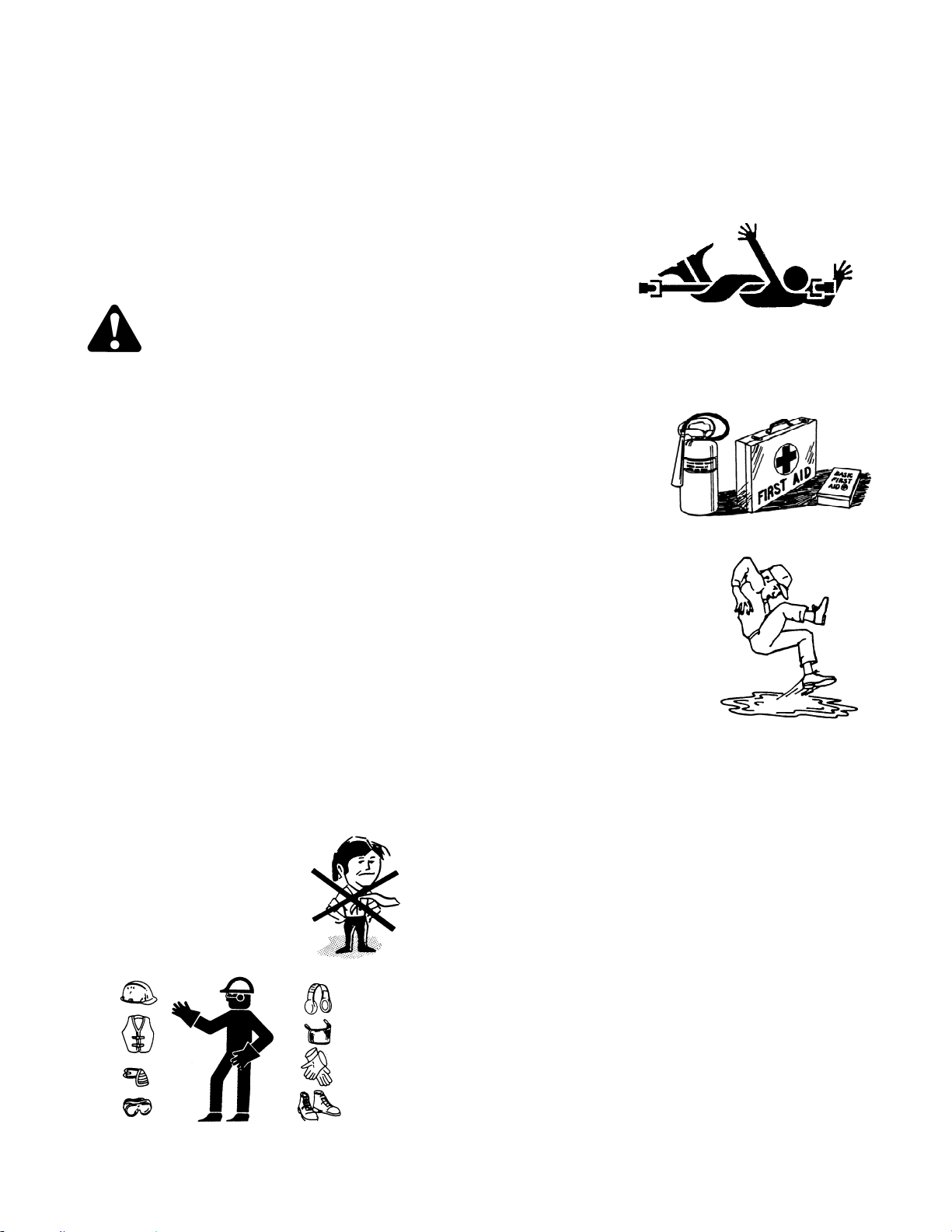
MAINTENANCE/SERVICE
169304 98 Rev. C
7 MAINTENANCE/SERVICE
The following instructions are provided to assist
the operator in the use of the M100 Windrower.
Detailed maintenance, service, and parts
information are contained in the Service
Instruction Manual and Parts Catalog that are
available from your dealer.
7.1 PREPARATION FOR SERVICING
WARNING
To avoid personal injury, before servicing
adapter/header or opening drive covers:
• Fully lower the header. If necessary to
service in the raised position, always
engage lift cylinder stops.
• Disengage drives.
• Stop engine and remove key.
• Wait for all moving parts to stop.
7.1.1 Welding Precautions
IMPORTANT
High currents and voltage spikes
associated with welding can cause
damage to electronic components. Before
welding on any part of the windrower or an
attached header, disconnect all electronic
module harness connections as well as
the battery cables. These electronic
modules include;
• Engine Control Module (ECM)
• Cab Display Module (CDM)
7.2 RECOMMENDED SAFETY
PROCEDURES
• Wear close-fitting
clothing and cover
long hair. Never wear
dangling items such
as scarves or
bracelets.
• Wear protective shoes with slip-resistant
soles, a hard hat, protective glasses or
goggles and heavy gloves.
• If more than one person is servicing the
machine at the same time, be aware that
rotating a driveline or other mechanically
driven
component
by hand (for
example,
accessing a
lube fitting)
will cause drive components in other
areas (belts, pulleys, and sickle) to move.
Stay clear of driven components at all
times.
• Be prepared if an
accident should
occur. Know
where the first aid
kit and fire
extinguishers are
located and how
to use them.
• Keep the service
area clean and dry.
Wet or oily floors are
slippery. Wet spots
can be dangerous
when working with
electrical equipment.
Be sure all electrical
outlets and tools are
properly grounded.
• Use adequate light for the job at hand.
• Replace all shields removed or opened
for service.
• Park on a level surface when possible.
Block wheels securely.
• Use only service and repair parts made
or approved by the equipment
manufacturer. Substituted parts may not
meet strength, design or safety
requirements.
• Keep the machine clean. Never use
gasoline, naphtha or any volatile material
for cleaning purposes. These materials
may be toxic and/or flammable.

MAINTENANCE/SERVICE
169304 99 Rev. C
7.3 MAINTENANCE SPECIFICATIONS
7.3.1 Recommended Fluids, Fuel, and
Lubricants
7.3.1.1 Fuel
FUEL SPEC SULPHUR
(by weight)
WATER &
SEDIMENT
(by weight)
CETANE
NO.
LUBRI
CITY
Diesel
Grade
No.2
ASTM
D-975
As Per
Spec
As Per
Spec
As Per
Spec
As Per
Spec
Diesel
Grade
No.1 &
2 mix *
n/a
1% Max.
0.5% Max.
Preferred
0.1% Max.
45-55
Cold
Weather/
High Alt.
460
HFRR
* Optional when operating temp below 0˚C. (32˚F.).
In extreme situations, when available fuels are
of poor quality or problems exist which are
peculiar to certain operations, additives can be
used. However, the engine manufacturer
recommends consultation with the fuel supplier
or engine manufacturer prior to use of fuel
additives. Among the situations where additives
can prove useful are the following:
• A cetane improver additive can be used with
low cetane fuels.
• A wax crystal modifier can help with fuels
with high cold filter plugging points (CFPP).
• An anti-icer can help prevent ice formation in
wet fuel during cold weather.
• An anti-oxidant or storage stability additive
can help with fuel system deposits and poor
storage stability.
• A lubricity enhancer can be used to increase
the lubricity of fuels so that they meet the
requirements given in the table on the
previous page.
Diesel fuel conditioner is available from your
dealer.
7.3.1.2 Fluids
FLUID SPEC DESCRIPTION USE
Anti-Freeze
ASTM
D-4985
Ethylene Glycol
With SCA
Engine
Coolant *
Air
Conditioning
Refrigerant
R134A Refrigerant
Cab Air
Conditioning
System.
Compressor
Oil
SP-15 Compressor Oil
Cab Air
Conditioning
Compressor
Lubricant
* Mix with equal parts of high quality, soft, de-ionized, or distilled
water.
7.3.1.3 Lubricants
LUBRICANT SPEC/DESCRIPTION USE
Grease
SAE Multi-Purpose.
High Temp. Extreme
Pressure (EP2) Performance
With 1% Max Molybdenum
Disulphide (NLGI Grade 2).
Lithium Base
As Required
Unless
Otherwise
Specified.
Engine Oil
SAE 15W40 Compliant With
SAE Specs For API Class SJ
And CH-4 Engine Oil.
Engine
Crankcase
Hydraulic Oil
SAE 15W40 Compliant With
SAE Specs For API Class SJ
And CH-4 Engine Oil
Windrower
Drive.
Header
Drive.
Gear Lubricant
SAE 85W-140
API Service Class GL-5.
Extreme Pressure Gear
Lubricant
Drive Wheel
Gears
Before Initial
Change.
SAE 75W-90
API Service Class GL-5.
Fully Synthetic Gear
Lubricant
(SAE J2360 Preferred)
Drive Wheel
Gears After
Initial
Change.
7.3.1.4 Capacities
ITEM CAPACITY
Fuel Tank 97 U.S. Gallons (378 liters)
Hydraulic Reservoir 11.5 U.S. Gallons (45 liters)
Drive Wheel 1.5 U.S. Quarts (1.4 liters)
Engine Cooling System 5.3 U.S. Gallons (20 liters)
Engine Crankcase 7.6 U.S. Quarts (7 liters)
Air Cond. Refrigerant 3.6 lb (1.63 kg)
Air Cond. Compressor 8.1 fl. oz. (240 cc)
7.3.1.5 Storage
Your machine can operate at top efficiency only
if clean fuel and lubricants are used.
• Use clean containers to handle all fuels and
lubricants.
• Store in an area protected from dust,
moisture, and other contaminants.
• Buy good quality, clean fuel from a reputable
dealer.
• Avoid storing fuel over long periods of time.
If you have a slow turnover of fuel in
windrower tank or supply tank, add fuel
conditioner to avoid condensation problems.
• Store fuel in a convenient place away from
buildings.
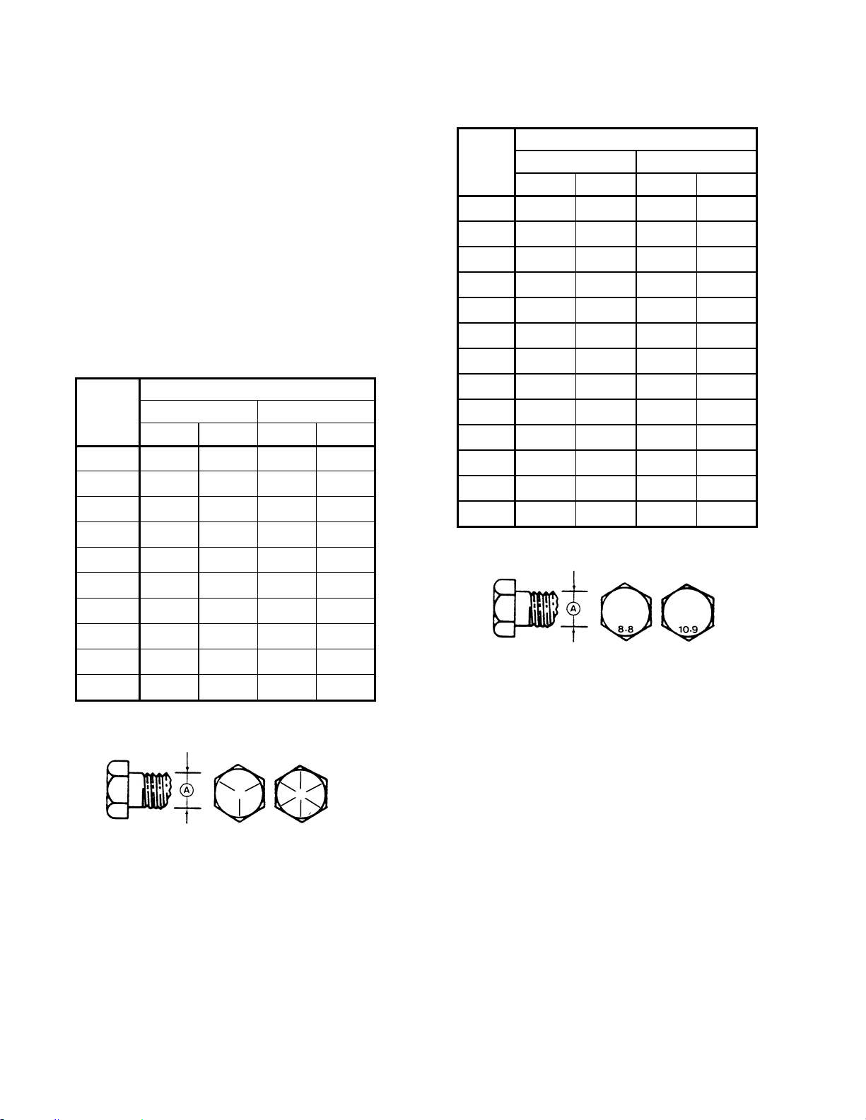
MAINTENANCE/SERVICE
169304 100 Rev. C
7.3.2 Recommended Torques
• Tighten all bolts to the torques specified in
chart unless otherwise noted throughout this
manual.
• Check tightness of bolts periodically, using
bolt torque chart as a guide.
• Replace hardware with the same strength
bolt.
• Torque figures are valid for non-greased or
non-oiled threads and heads unless
otherwise specified. Do not grease or oil
bolts or capscrews unless specified in this
manual. When using locking elements,
increase torque values by 5%.
7.3.2.1 SAE Bolts
BOLT
DIA. "A"
in.
NC BOLT TORQUE*
SAE 5 SAE 8
lbf·ft N·m lbf·ft N·m
8 1/4 9 9 10 12 11 11 12 15
13 5/1
6
14 18 15 24 16 25 17 34
18 3/8 19 32 20 43 21 41 22 56
23 7/1
6
24 50 25 68 26 70 27 95
28 1/2 29 75 30 10
2
31 10
5
32 14
2
33 9/1
6
34 11
0
35 14
9
36 14
9
37 20
2
38 5/8 39 15
0
40 20
3
41 20
0
42 27
1
43 3/4
44 26 45 35
46 36
5
47 49
5
48 7/8 49 42
0
50 56
9
51 60
0
52 81
3
53 1 54 64
0
55 86
7
56 89
0
57 12
0
* Torque categories for bolts and capscrews are identified by their
head markings.
57.1.1.1 Metric Bolts
BOLT
DIA.
"A"
NC BOLT TORQUE*
8.8 10.9
lbf·ft N·m lbf·ft N·m
M3 0.4 0.5 1.3 1.8
M4 2.2 3 3.3 4.5
M5 4 6 7 9
M6 7 10 11 15
M8 18 25 26 35
M10 37 50 52 70
M12 66 90 92 125
M14 103 140 148 200
M16 166 225 229 310
M20 321 435 450 610
M24 553 750 774 1050
M30 1103 1495 1550 2100
M36 1917 2600 2710 3675
* Torque categories for bolts and capscrews are identified by their
head markings.
SAE-5 SAE-8
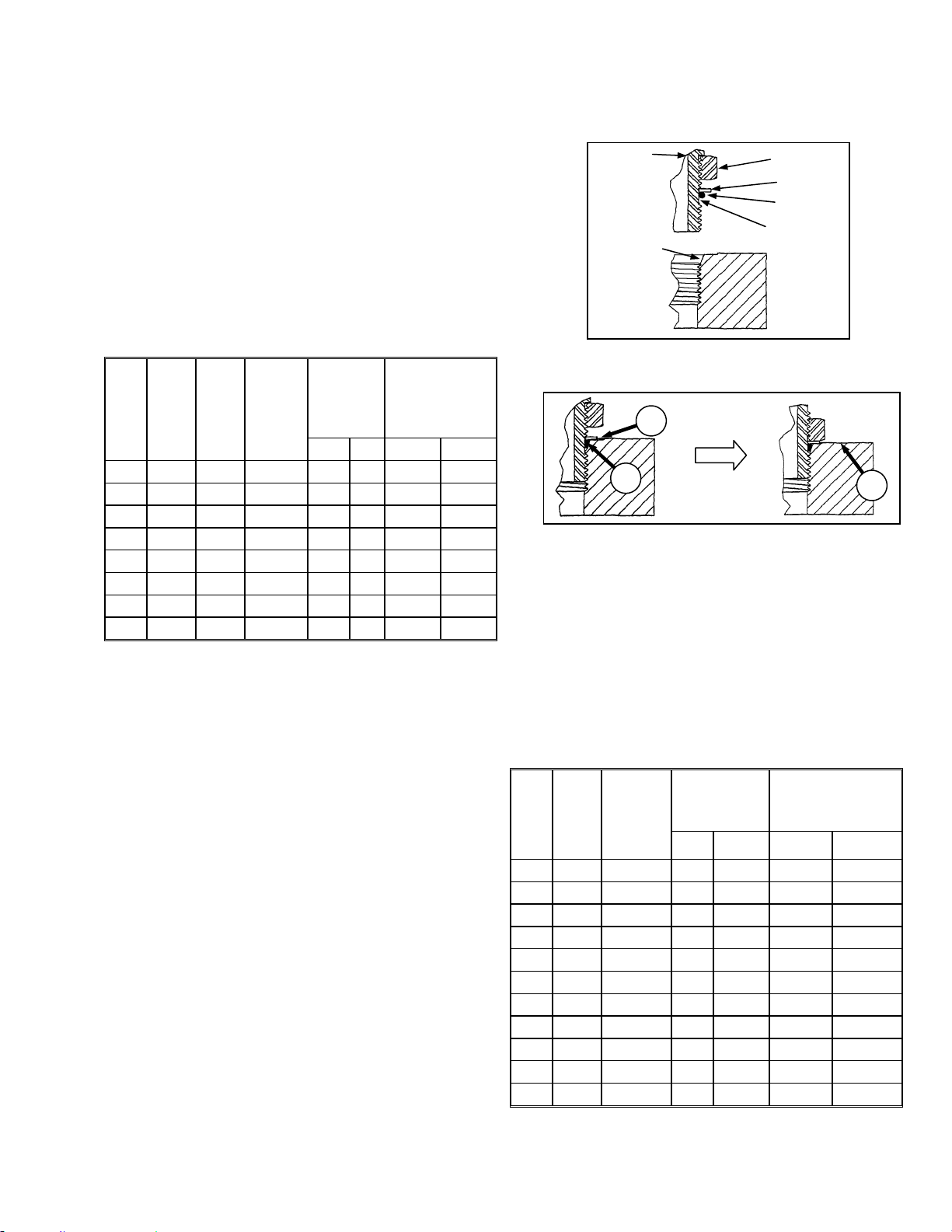
MAINTENANCE/SERVICE
169304 101 Rev. C
57.1.1.2 Flare Type Hydraulic Fittings
a. Check flare and flare seat for defects that might
cause leakage.
b. Align tube with fitting before tightening.
c. Lubricate connection and hand tighten swivel
nut until snug.
d. To prevent twisting the tube(s), use two
wrenches. Place one wrench on the connector
body and with the second tighten the swivel nut
to the torque shown.
SAE
NO.
TUBE
SIZE
O.D.
(in.)
THD
SIZE
(in.)
NUT
SIZE
ACROSS
FLATS
(in.)
TORQUE
VALUE*
RECOMMENDED
TURNS TO
TIGHTEN
(AFTER FINGER
TIGHTENING)
ft·lbf N·m Flats Turns
3 3/16
3/8
7/16 6 8 1 1/6
4 1/4
7/16
9/16 9 12 1 1/6
5 5/16
1/2
5/8 12 16 1 1/6
6 3/8
9/16
11/16 18 24 1 1/6
8 1/2
3/4
7/8 34 46 1 1/6
10 5/8
7/8
1 46 62 1 1/6
12 3/4
1-1/16
1-1/4 75 102 3/4 1/8
14 7/8
1-3/8
1-3/8 90 122 3/4 1/8
* The torque values shown are based on lubricated connections
as in reassembly.
57.1.1.3 O-ring Type Hydraulic Fittings
a. Inspect O-ring and seat for dirt or obvious
defects.
b. On angle fittings, back off the lock nut until
washer (A) bottoms out at top of groove (B) in
fitting.
c. Hand tighten fitting until back up washer (A) or
washer face (if straight fitting) bottoms on part
face (C) and O-ring is seated.
d. Position angle fittings by unscrewing no more
than one turn.
e. Tighten straight fittings to torque shown.
f. Tighten angle fittings to torque shown in the
following table while holding body of fitting with a
wrench.
SAE
NO.
THD
SIZE
(in.)
NUT SIZE
ACROSS
FLATS
(in.)
TORQUE
VALUE*
RECOMMENDED
TURNS TO TIGHTEN
(AFTER FINGER
TIGHTENING)
ft·lbf N·m Flats Turns
3 3/8 1/2 6 8 2 1/3
4 7/16 9/16 9 12 2 1/3
5 1/2 5/8 12 16 2 1/3
6 9/16 11/16 18 24 2 1/3
8 3/4 7/8 34 46 2 1/3
10 7/8 1 46 62 1-1/2 1/4
12 1-1/16 1-1/4 75 102 1 1/6
14 1-3/16 1-3/8 90 122 1 1/6
16 1-5/16 1-1/2 105 142 3/4 1/8
20 1-5/8 1-7/8 140 190 3/4 1/8
24 1-7/8 2-1/8 160 217 1/2 1/12
* The torque values shown are based on lubricated connections
as in reassembly.
LOCKNUT
SEAT
WASHE
R
O-RING
GROOVE
FITTING
A
B
C

MAINTENANCE/SERVICE
169304 102 Rev. C
57.1.2 Conversion Chart
QUANTITY
INCH-POUND UNITS
FACTOR
SI UNITS (METRIC)
UNIT NAME ABBR. UNIT NAME ABBR.
Area acres acres x 0.4047 = hectares ha
Flow US gallons per minute (gpm) x 3.7854 = liters per min L/min
Force pounds force lbf x 4.4482 = Newtons N
Length
inch in. x 25.4 = millimeters mm
foot ft x 0.305 = meters m
Power horsepower hp x 0.7457 = kilowatts kW
Pressure pounds per square inch psi
x 6.8948 = kilopascals kPa
x .00689 = megapascals MPa
Torque
pound feet or foot pounds lbf·ft or ft·lbf x 1.3558 = newton meters N·m
pound inches or inch pounds lbf·in. or in·lbf x 0.1129 = newton meters N·m
Temperature degrees Fahrenheit ˚F (F- 32) x 0.56 = Celsius ˚C
Velocity
feet per minute ft/min x 0.3048 = meters per min m/min
feet per second ft/s x 0.3048 = meters per sec m/s
miles per hour mph x 1.6063 = kilometers per hour km/h
Volume
US gallons US gal. x 3.7854 = liters L
ounces oz. x 29.5735 = milliliters ml
cubic inches in.
3
x 16.3871 = cubic centimeters cm
3
or cc
Weight pounds lb x 0.4536 = kilograms kg
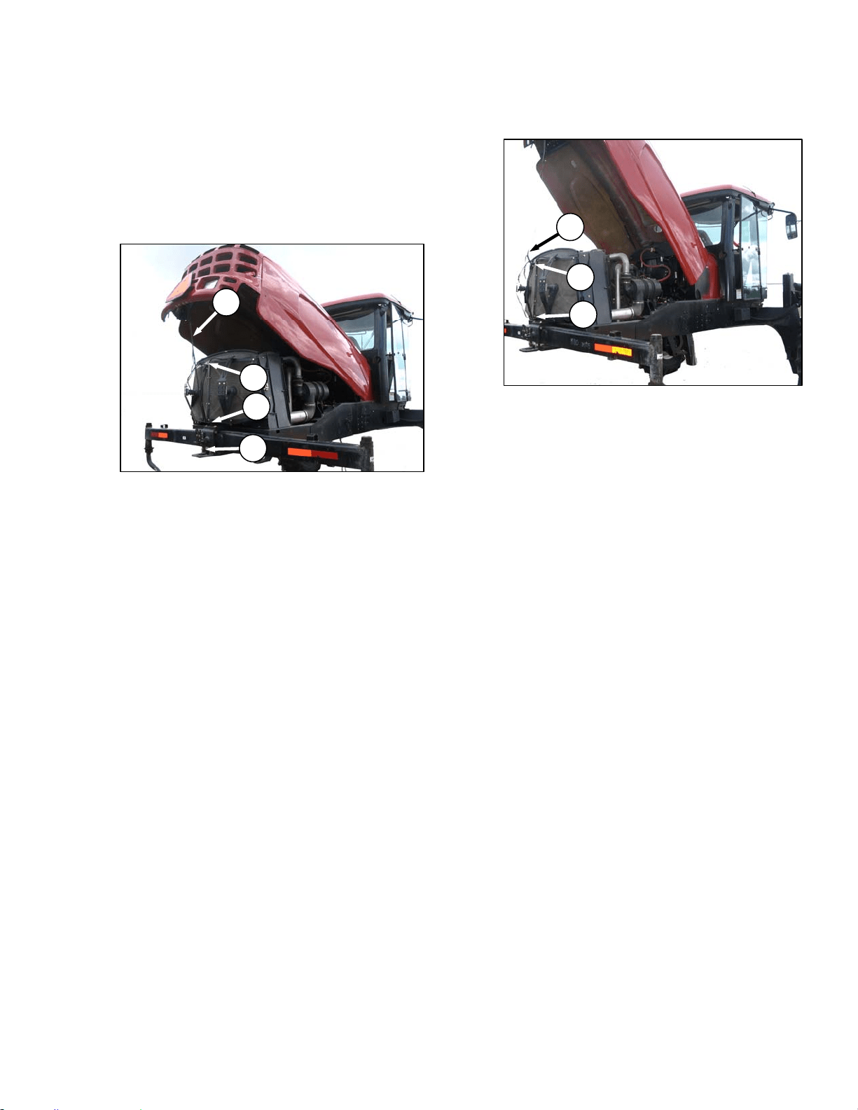
MAINTENANCE/SERVICE
169304 103 Rev. C
57.2 ENGINE COMPARTMENT HOOD
The engine hood has two open positions. The
lowest is for general maintenance such as
checking and adding fluid, servicing the cooling
box, etc. The highest position accommodates
full access to the engine bay.
a. Open the hood at the lowest position as follows:
1. Locate latch (A) behind grill and lift to
release hood.
2. Raise hood until strap (B), which should be
looped under hooks (C) and (D), stops it at
approximately a 40 degree angle.
b. To close hood:
1. Pull down on strap (B), grasp the hood when
within reach and lower until hood engages
latch (A).
c. Open the hood at the highest position as follows:
1. Open hood to lowest position.
2. Remove strap from hooks (C) and (D) and
allow hood to raise fully to approximately 65
degrees.
d. To close hood:
1. Grasp the strap at (B) and loop under upper
hook (C).
2. Pull down on strap and loop under lower
hook (D).
IMPORTANT
Failure to hook strap may result in it
becoming entangled with the screen
cleaners or the latch.
3. Pull down on strap, grasp the hood when
within reach and lower until hood engages
latch (A).
B
A
D
C
B
C
D
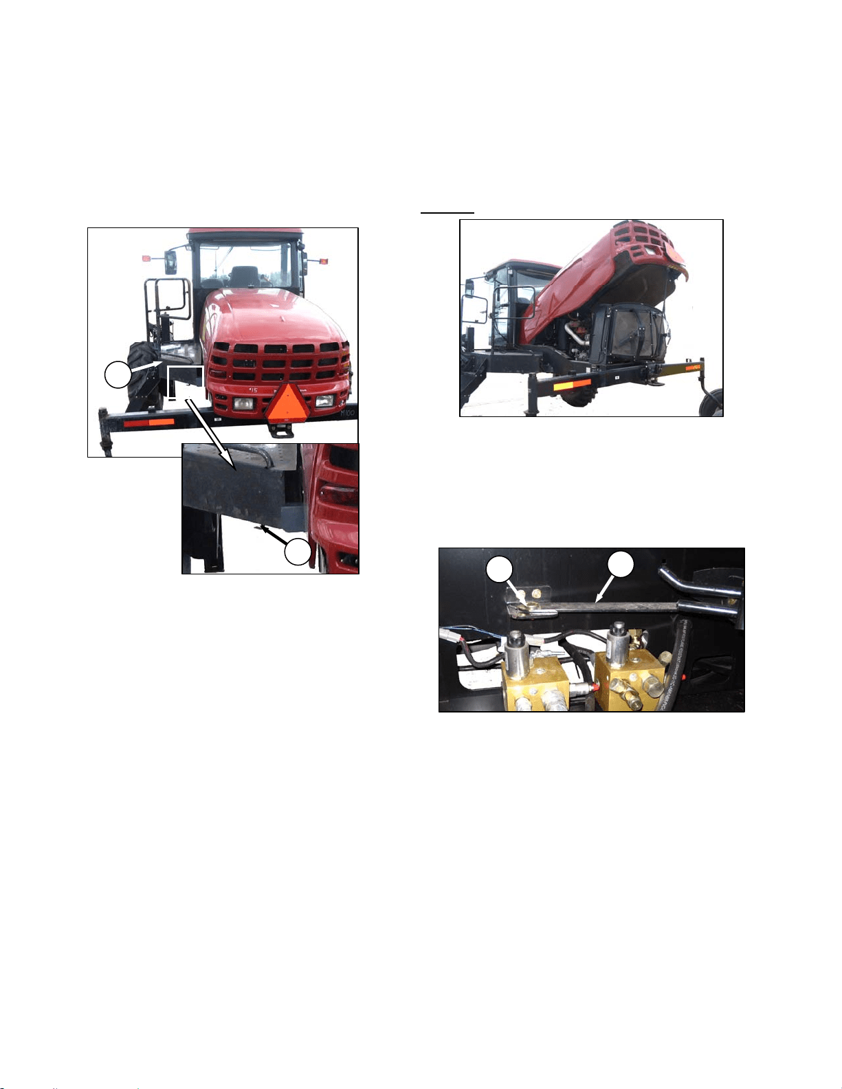
MAINTENANCE/SERVICE
169304 104 Rev. C
57.3 MAINTENANCE PLATFORM
A swing away platform/stair unit is provided on
the left side of the windrower for access to the
operator’s station and engine bay maintenance.
57.3.1 Opening/Closing Platform
a. Push latch (A) down and pull platform (B) toward
walking beam until it stops and latch re-engages
in open position.
b. To move platform back to closed position,
release latch (A) and move platform forward until
it stops and latch re-engages.
57.3.2 Opening/Closing Platform for Major
Servicing
To improve access to the hydraulics plumbing,
the platform can be swung away from the
windrower.
To Open
:
a. Open engine compartment hood to lowest
position.
IMPORTANT
Failure to open hood will result in damage
to the hood when the platform is
repositioned.
b. Unlock latch (A) and move platform (B) toward
open position.
c. Remove nut and bolt (C) and swing link (D) clear
of valve block.
(continued next page)
D
C
B
A
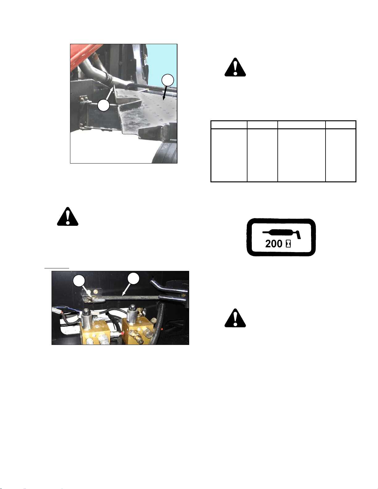
MAINTENANCE/SERVICE
169304 105 Rev. C
d. At the same time pull front end of platform away
from frame while moving it towards the walking
beam. Aft corner (E) of platform should project
slightly into engine bay when optimum opening
is reached.
CAUTION
Do not stand on the platform in the unlocked
position. It is unstable and may result in a
fall.
e. Swing link (D) under platform.
To Close
:
a. Swing link (D) out from under platform all the
way forward.
b. Move platform front end inboard while moving it
away from the walking beam.
c. Position link (D) on bracket and install bolt and
nut (C). Do not fully tighten.
d. Move platform to closed position, ensuring it is
locked.
e. Close engine compartment hood.
57.4 LUBRICATING THE WINDROWER
WARNING
To avoid personal injury, before servicing
windrower or opening drive covers, follow
procedures in Section 7.1, Preparation for
Servicing.
Recommend Lubricant
LUBRICANT SPEC DESCRIPTION USE
Grease
SAE Multi-
Purpose.
High Temp.
Extreme Pressure
(EP2)
Performance With
1% Max
Molybdenum
Disulphide (NLGI
Grade 2).Lithium
Base
As Required
Unless
Otherwise
Specified.
The greasing points are marked on the machine
by decals showing a grease gun and grease
interval in hours of operation. See illustration
below.
Log hours of operation and use the
"Maintenance Checklist" provided to keep a
record of scheduled maintenance. Refer to
Section 7.13, Maintenance Schedule.
57.4.1 Procedure
DANGER
Stop engine and remove key from ignition
before leaving operator's seat for any
reason. A child or even a pet could engage
an idling machine.
a. Wipe grease fitting with a clean cloth before
greasing, to avoid injecting dirt and grit.
b. Inject grease through fitting with grease gun until
grease overflows fitting, except where noted.
c. Leave excess grease on fitting to keep out dirt.
d. Replace any loose or broken fittings
immediately.
e. If fitting will not take grease, remove and clean
thoroughly. Also clean lubricant passageway.
Replace fitting if necessary.
E
B
D
C
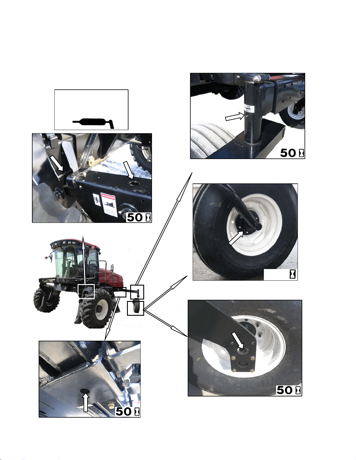
MAINTENANCE/SERVICE
169304 106 Rev. C
57.4.2 Lubrication Points
Refer to the illustrations on the following page
for identifying the various locations that require
lubrication.
TOP LINK – TWO FITTINGS
(
BOTH SIDES
)
CASTER PIVOT
(
BOTH SIDES
)
High Temp. Extreme Pressure
(EP2) Performance With 1%
Max Molybdenum Disulphide
(NLGI Grade 2).Lithium Base
WALKING BEAM PIVOT
)
FORKED CASTER SPINDLE BEARINGS
TWO PLACES (BOTH WHEELS)
FORMED CASTER WHEEL BEARING
1 PLACE (BOTH WHEELS)
200

MAINTENANCE/SERVICE
169304 107 Rev. C
57.5 OPERATOR’S STATION
57.5.1 Seat Belts
Keep the operator and trainer seat belts in good
condition as follows:
a. Keep sharp edges and items that can cause
damage away from the belts.
b. From time to time, check belts, buckles,
retractors, tethers, slack take-up system and
mounting bolts for damage.
c. Replace all parts that have damage or wear.
d. Replace belts that have cuts that can weaken
the belt.
e. Check that bolts are tight on the seat bracket or
mounting.
f. Keep seat belts clean and dry. Clean only with a
soap solution and warm water. DO NOT use
bleach or dye on the belts, as this may weaken
the material.
57.5.2 Safety Systems
Perform the following checks on the operator’s
presence and engine lock-out systems annually
or every 500 hours whichever occurs first.
57.5.2.1 Operator’s Presence System
a. With the windrower engine running, place the
GSL in Neutral and turn the steering wheel until
it locks.
b. With everyone clear of the machine, engage
header drive switch;
1. After header drives are running, stand up
out of the seat. In approximately 5 seconds
the header should shut off.
2. If not, the operator presence system
requires adjustment. See your MacDon
dealer.
NOTE
To restart the header, the operator must
move the header engage switch to “OFF”
position and back to the “ON” position
again.
c. With the windrower engine running, place the
GSL in Neutral but out of N-DETENT;
1. Stand up. After 2 seconds, the lower display
will flash “NOT IN NEUTRAL” accompanied
by a continuous loud tone. Move the GSL
into N-DETENT to cancel the alarm.
2. If there is no warning, the operator presence
system requires adjustment. See your
MacDon dealer.
d. With the windrower in forward motion at
approximately 2-3 mph;
1. Stand up out of the seat.
2. The CDM will flash “NO OPERATOR” on the
upper line, and “ENGINE SHUTS DOWN
5…4…3…2…1…0” accompanied by a
steady tone.
3. If not, the operator presence system
requires adjustment. See your MacDon
dealer.
57.5.2.2 Engine Interlock
a. With the engine shut down and the header drive
switch engaged, try to start the engine. If the
engine turns over, the system requires
adjustment. See your MacDon dealer.
b. With the engine shut down, steering wheel not
centered, and the GSL in neutral but not in N-
DETENT, try to start the engine. The CDM will
flash “NOT IN NEUTRAL” on the display upper
line, and “CENTER STEERING WHEEL” on the
lower line, accompanied by a short beep with
each flash, and the engine should not turn over.
If the engine turns over, the system requires
adjustment. See your MacDon dealer.
A properly functioning system should operate as
follows, if not, see your MacDon dealer.
• The starter should engage ONLY
when the
GSL is in N-DETENT, steering wheel locked
in the CENTER position, and the header
drive switch is in the OFF position.
• Under the above conditions, the brake
should engage and the machine should not
move after engine start-up.
• The steering wheel should not lock with the
engine running and the GSL is out of the N-
DETENT.
• The machine should not move with the
engine running and with the steering wheel
still centered, when the GSL is pulled
straight out of N-DETENT (not in forward or
reverse).
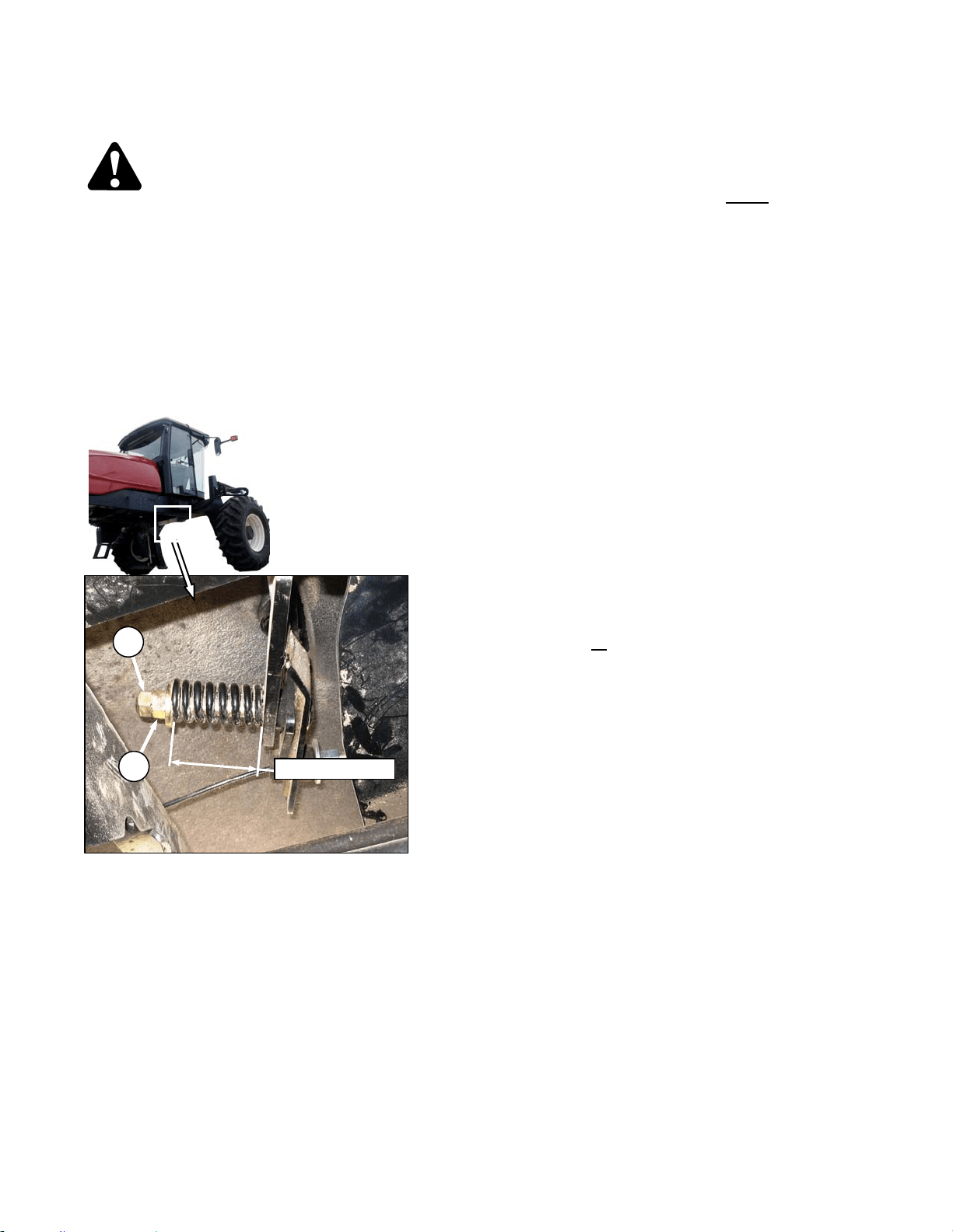
MAINTENANCE/SERVICE
169304 108 Rev. C
57.5.3 Traction Drive Adjustments
DANGER
Stop engine and remove key from ignition
before leaving operator's seat for any
reason. A child or even a pet could engage
an idling machine.
57.5.3.1 GSL Fore-Aft Movement
The GSL should remain as positioned by the
operator and yet can be moved without
excessive force. The spring is set at the factory
to 2.50 in. (64 mm) shown on the illustration. If
necessary, adjust as follows:
a. Hold nut (A) from turning and loosen jam-nut
(B).
b. To increase the pivot resistance, turn the nut (A)
clockwise to compress the spring.
c. To decrease the resistance, turn the nut (A)
counterclockwise to release the spring tension.
d. Hold nut (A) from turning and tighten jam-nut
(B).
57.5.3.2 Neutral Interlock Checks
A properly functioning system should operate as
follows:
• The starter should engage ONLY
when the
GSL is in N-DETENT, steering wheel locked
in the CENTER position, and the header
drive switch is in the OFF position.
• Under the above conditions, the brake
should engage and the machine should not
move after engine start-up.
• The steering wheel should not lock with the
engine running and the GSL is out of the N-
DETENT.
• The machine should not move with the
engine running and with the steering wheel
still centered, when the GSL is pulled
straight out of N-DETENT (not in forward or
reverse).
Any problem with the neutral lock and steering
controls could be caused by loose, worn, or
improperly adjusted parts. Perform the following
checks if the neutral interlock system is not
functioning as described above. See Table next
page.
IMPORTANT
When servicing this area, it is important to
perform all
of the checks to avoid missing
the problem and providing only a
temporary fix.
B
2.50 in. (64 mm)
A

MAINTENANCE/SERVICE
169304 109 Rev. C
PROBLEM CHECK
ITEM
NO.
Steering wheel will not lock in neutral. GSL Position 7.7.3.3
Cable Tension 7.7.3.4
Neutral Lock 7.7.3.5
Neutral Start Switch 7.7.3.6
Ground speed lever will not go into reverse or forward. Cable Tension 7.7.3.4
Ground speed lever rattles in neutral Cable Tension 7.7.3.4
Neutral Lock 7.7.3.5
Ground speed lever not spring loaded towards the center of forward travel slot Cable Tension 7.7.3.4
Neutral Lock 7.7.3.5
Steering wheel locks in neutral, but neutral start switch does not compress Neutral Start Switch 7.7.3.6
Neutral Lock Adjust Bolts 7.7.3.7
Cable Tension 7.7.3.4
GSL Position 7.7.3.3
Neutral Lock 7.7.3.5
Perform Neutral Set-up
Procedure.
7.7.4
Machine "growls" severely or moves after engine start-up. Neutral Start Switch 7.7.3.6
Neutral Lock Adjust Bolts 7.7.3.7
Cable Tension 7.7.3.4
GSL Fore-Aft Movement 7.7.3.1
GSL Position 7.7.3.3
Neutral Lock 7.7.3.5
Loose Hardware 7.7.3.8
Perform Neutral Set-up
Procedure.
7.7.4
Steering wheel locks in neutral only after several left to right rotations of wheel Neutral Lock Adjust Bolts 7.7.3.7
Cable Tension 7.7.3.4
GSL Position 7.7.3.3
Neutral Lock 7.7.3.5
Perform Neutral Set-up
Procedure.
7.7.4
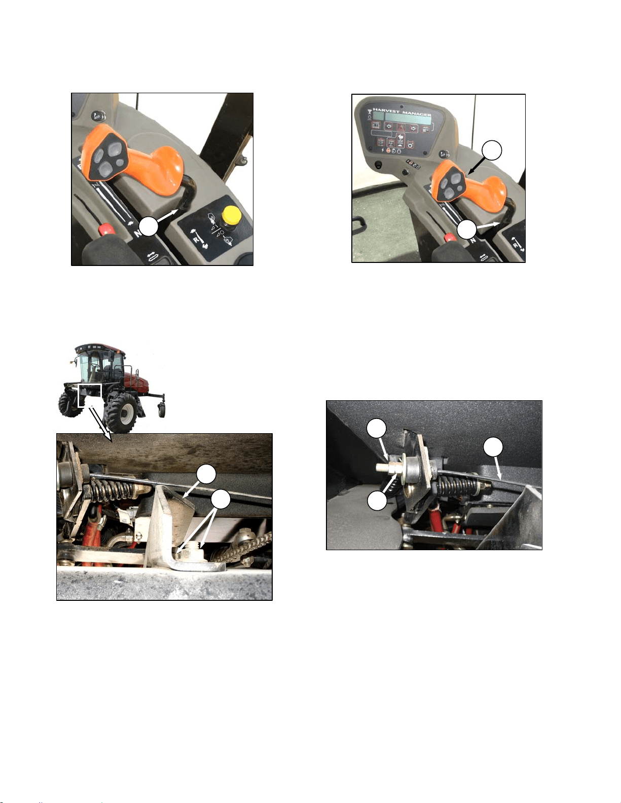
MAINTENANCE/SERVICE
169304 110 Rev. C
57.5.3.3 GSL Position
The GSL should be centered fore-aft (A) in the
N-Detent slot when the steering wheel is
centered and locked.
If necessary, adjust as follows:
IMPORTANT
Neutral Interlock must be properly
adjusted before adjusting GSL position.
a. Lock pintle arms.
b. Loosen nuts (B).
c. Hold GSL in center of N-Detent slot to locate
support (C).
d. Tighten nuts (B) and torque to 80-90 ft·lbf (108-
122 Nm).
57.5.3.4 Cable Tension
The GSL (D) should easily move into the N-
DETENT (E) by itself, and the cable (F) should
be tight when the GSL is at the right hand side
of the neutral detent on side console. The
neutral start switch should also be fully
compressed. If the cable is too tight, it will
prevent the neutral start switch from fully
compressing and prevent proper engagement of
adjustment bolts on pintle arm.
Adjust the cable tension as follows:
a. Hold nut (G) from turning and loosen jam-nut
(H).
b. To increase the tension, turn the nut (G)
clockwise.
c. To decrease the cable tension, turn the nut (G)
counterclockwise.
d. Hold nut (G) from turning and tighten jam-nut
(H).
A
E
D
B
C
H
G
F
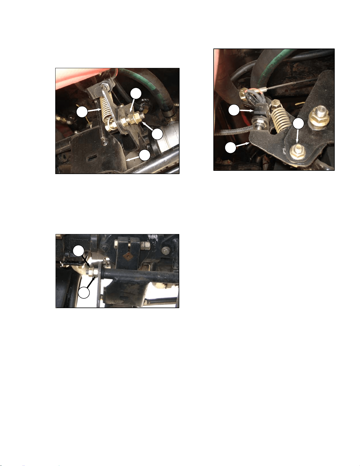
MAINTENANCE/SERVICE
169304 111 Rev. C
57.5.3.5 Neutral Lock Structure
a. Check for proper movement of interlock support
structure as follows:
1. Disconnect spring (A) to unload pivots.
2. Check that support (B) rotates freely and
that there is no fore-aft movement of
structure.
3. If no adjustment is required, reconnect
spring (A).
b. If necessary, adjust as follows:
1. Loosen outer nut (C).
2. Turn inner nut (D) until washer just contacts
the plastic bushing. This pivot must allow
free rotation of the support structure.
3. Hold inner nut (D) with a wrench and tighten
outer nut (C) against nut (D).
4. Loosen outer nut (E).
5. Turn inner nut (F) until washer contacts the
front support. Check again for free rotation
of the structure with no fore-aft movement.
6. Hold inner nut (F) with a wrench and tighten
outer nut (E) against inner nut (F).
7. Torque outer nuts (C) & (E) to 60-70 ft·lbf
(80-90 Nm).
8. Reconnect spring (A).
57.5.3.6 Neutral Start Switch
The neutral start switch (G) must be closed
before the engine can be started. The switch is
closed when the neutral interlock on the pump is
activated by positioning the GSL into N-DETENT
and locking the steering wheel in centre position.
When the switch closes, and machine starts and
runs, the brakes continue to be applied to the
drive wheels as park brake solenoid 3 is
energized preventing brake release. The neutral
switch is located on the frame adjacent to the
hydrostatic transmission.
a. Check that electrical connections are good at
neutral start switch (G).
b. Check that the plunger of switch is fully
compressed when the steering is locked and the
GSL is fully in N-DETENT. Adjust switch
support if required as follows:
1. Loosen nut (H) and adjust support (J) as
required.
2. Tighten nut (H).
IMPORTANT
Do not over-adjust switch support, as this
will prevent pintle arms from locking.
D
C
A
B
F
E
G
H
J

MAINTENANCE/SERVICE
169304 112 Rev. C
57.5.3.7 Neutral Lock Adjustment Bolts
The neutral lock adjustment bolts must fully
engage the pintle arms. Check and adjust as
follows:
a. Ensure GSL is in N-DETENT position and the
steering wheel is locked in the centre position.
b. Shut down the engine.
c. Using a feeler gauge, gap between pivot
channel (A) and rear pintle arm (B) should be
0.04-0.20 inch (1-5 mm).
d. If required, adjust the interlock release cable (C)
as follows:
1. Loosen jam nut (D) and turn nut (E)
counterclockwise to increase the gap and
clockwise to decrease.
2. Tighten jam nut (D) against nut (E).
3. Check neutral start switch plunger is fully
depressed.
57.5.3.8 Loose Hardware
Check all hardware (not included in the previous
checks) is properly tightened to torque
specifications on ground speed controls, control
rods, pump pintle arms and neutral start
mechanisms.
0.08-0.20 in. (2-5 mm)
A
B
80-90 ft·lbf (108-122 Nm) (2 PLCS)
5-10 ft·lbf (6.8-13.6 Nm) (3 PLCS)
5-10 ft·lbf (6.8-13.6 Nm) (2 PLCS)
D
E
C
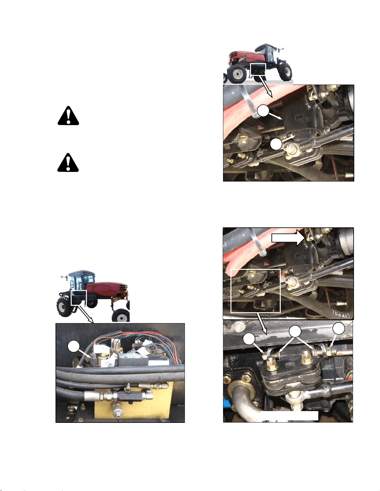
MAINTENANCE/SERVICE
169304 113 Rev. C
57.5.4 Neutral Set-Up Procedure
This procedure should be performed only after
the preceding checks and adjustments have
failed to solve the neutral lock/steering problem.
This procedure will eliminate machine
movement in neutral and will improve neutral
locking ability.
CAUTION
Use jack-stands with a minimum capacity of
3 tons (2720 kg) to provide adequate support
for machine.
DANGER
Never attempt neutral set-up procedure
without raising front wheels off the ground
so they are free to turn. Failure to raise front
wheels will result in machine runaway,
causing severe personal injury or death.
a. Detach header and remove hay conditioner
forming shields from under windrower.
b. Raise front of machine high enough to allow
both wheels to turn freely and support with jack-
stands. See "Jacking Procedure" under Wheel &
Tire Maintenance in this section.
c. Open maintenance platform.
d. Disconnect electrical connector V3 (wire 2-2002)
(A) at brake solenoid 3.
e. Ensure GSL is fully in N-DETENT and that
neutral lock mechanism (B) has engaged pintle
arms (C).
f. Start engine and run at 1100 rpm.
g. Adjust REAR pintle interlock as follows:
1. Loosen jam-nuts (D) and back off adjusting
bolts (E) in rear pintle arm.
(continued next page)
A
B
C
D
FWD
REAR PINTLE
E
D
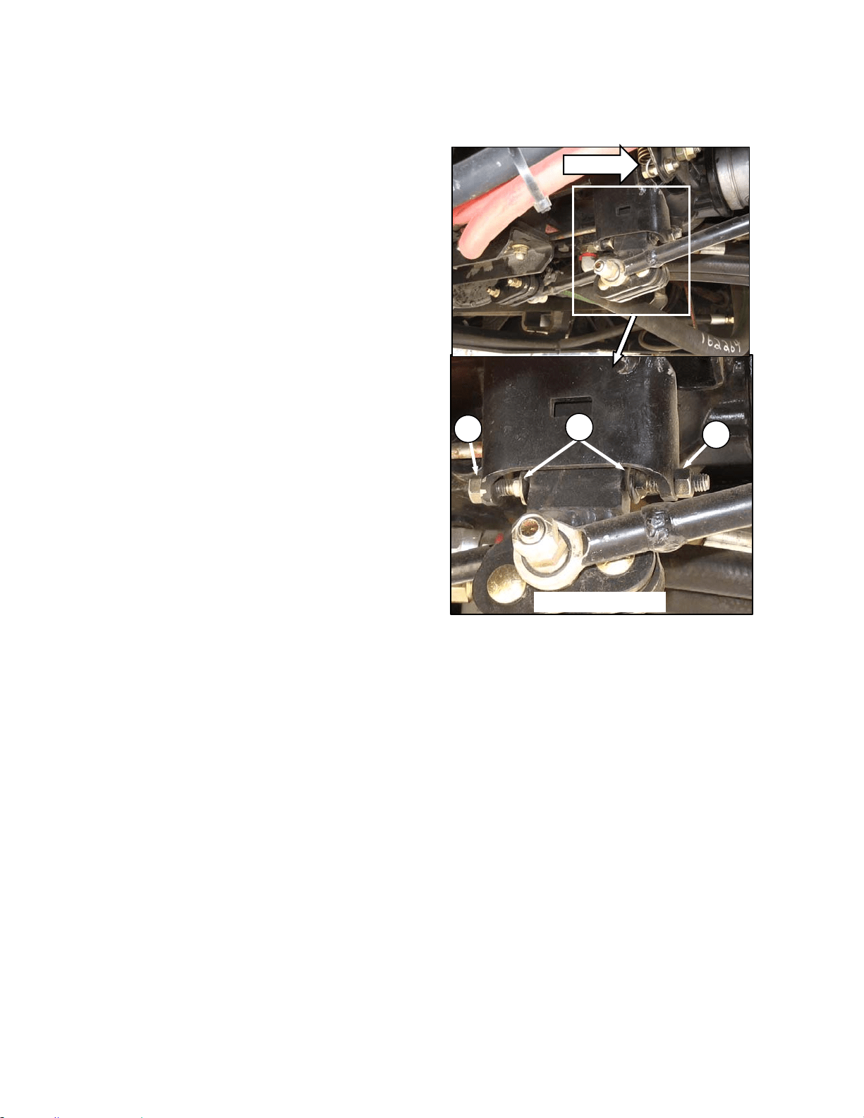
MAINTENANCE/SERVICE
169304 114 Rev. C
2. Move pintle arm a small amount forward and
hold so that LH wheel rotates forward for 2
or 3 seconds.
3. Move pintle arm a small amount rearward
and hold so that LH wheel rotates backward
for 2 or 3 seconds.
4. Position pintle arm so that the LH wheel
remains stationary and the pump is the
quietest to obtain the exact neutral position.
5. Turn the forward adjusting bolt (E) by hand
until it contacts the pintle arm.
6. Move the pintle arm firmly against the
adjusting bolt to check the setting – it’s
acceptable for the LH wheel to just begin to
creep forward. Hand tighten the jam-nut (D)
at the forward adjusting bolt.
7. Return pintle arm to the neutral position.
8. Turn the rear adjusting bolt (E) by hand until
it contacts the pintle arm.
9. Move the pintle arm firmly against the rear
adjusting bolt to check the setting – it’s
acceptable for the LH wheel to just begin to
creep backward. Hand tighten the jam-nut
(D) at the rear adjusting bolt.
10. Verify the adjusting bolt setting by again
moving the pintle arm forward, then
rearward to check that the LH wheel just
begins to creep in both cases.
11. Fully tighten jam-nuts on both adjusting
bolts. Ensure that the bolts do not rotate as
the jam-nuts are tightened.
12. Check that the rear interlock engages and
disengages freely onto the pintle arm in the
neutral position.
h. Adjust FRONT pintle interlock (actuates RH
wheel) using same procedure for the REAR
pintle:
i. Apply a small amount of grease to the head of
the adjusting bolts.
j. Shut-off engine.
k. Check GSL position in N-DETENT and adjust as
necessary. See 7.7.3.3.
l. Reconnect connector V3 at brake solenoid 3.
m. Close maintenance platform.
n. Lower machine to ground.
D
FWD
FRONT PINTLE
D
E
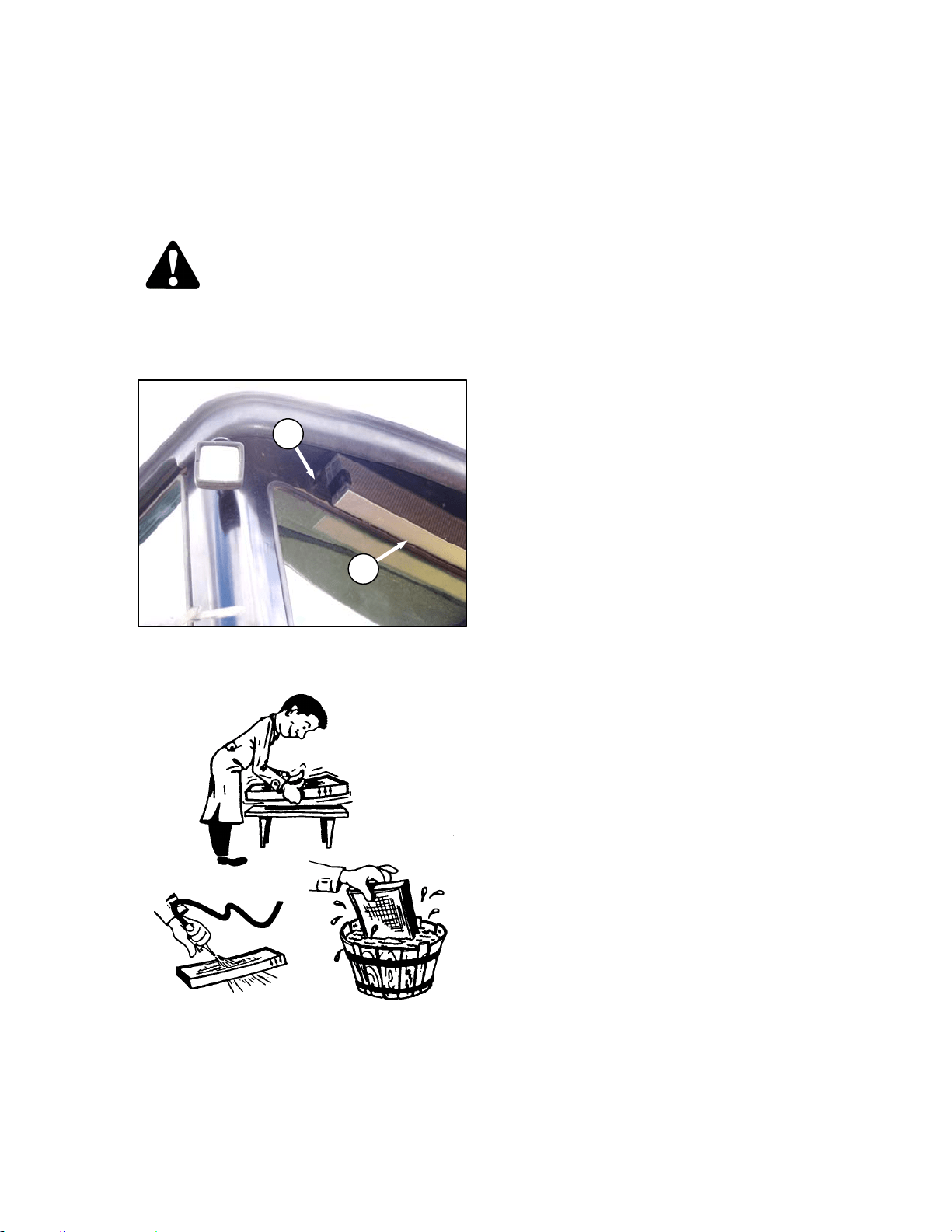
MAINTENANCE/SERVICE
169304 115 Rev. C
57.5.5 HVAC System
57.5.5.1 Fresh Air Intake Filter
The fresh air filter is located under the cab roof
behind the rear window and should be serviced
daily. Service the filter as follows:
DANGER
Stop engine and remove key from ignition
before leaving operator's seat for any
reason. A child or even a pet could engage
an idling machine.
a. Loosen knob (A) and slide retainer out to
release filter (B) from rear of cab roof.
b. Tap filter gently on a flat surface, dirty side
down. Do not tap on a tire, treads may damage
filter pleats.
c. Direct compressed air (100 psi [700 kPa]
maximum) through filter in opposite direction of
air flow arrows.
d. Wash filter as required:
1. Soak 15 minutes in warm water (not over
100°F [40°C]) with Filter Element Cleaner,
(Donaldson D 1400 or equivalent).
2. Rinse thoroughly with clean water,
(maximum pressure 40 psi [275 kPa]).
3. Shake excessive water from filter and allow
element to dry. Do not use compressed air
to dry filter; it may rupture the wet element.
Protect element from freezing until dry.
e. Inspect filter before installing as follows:
1. Hold a bright light on one side element and
check carefully for holes. Discard any
element which shows the slightest hole.
2. Be sure outer screen is not dented. Vibration
would quickly wear a hole in the filter.
3. Be sure filter gasket is in good condition. If
gasket is damaged or missing, replace
element
f. If element is coated with oil or soot, replace the
element.
g. Reinstall filter, making sure air flow arrows point
towards cab.
B
A
CLEANING AIR FILTER
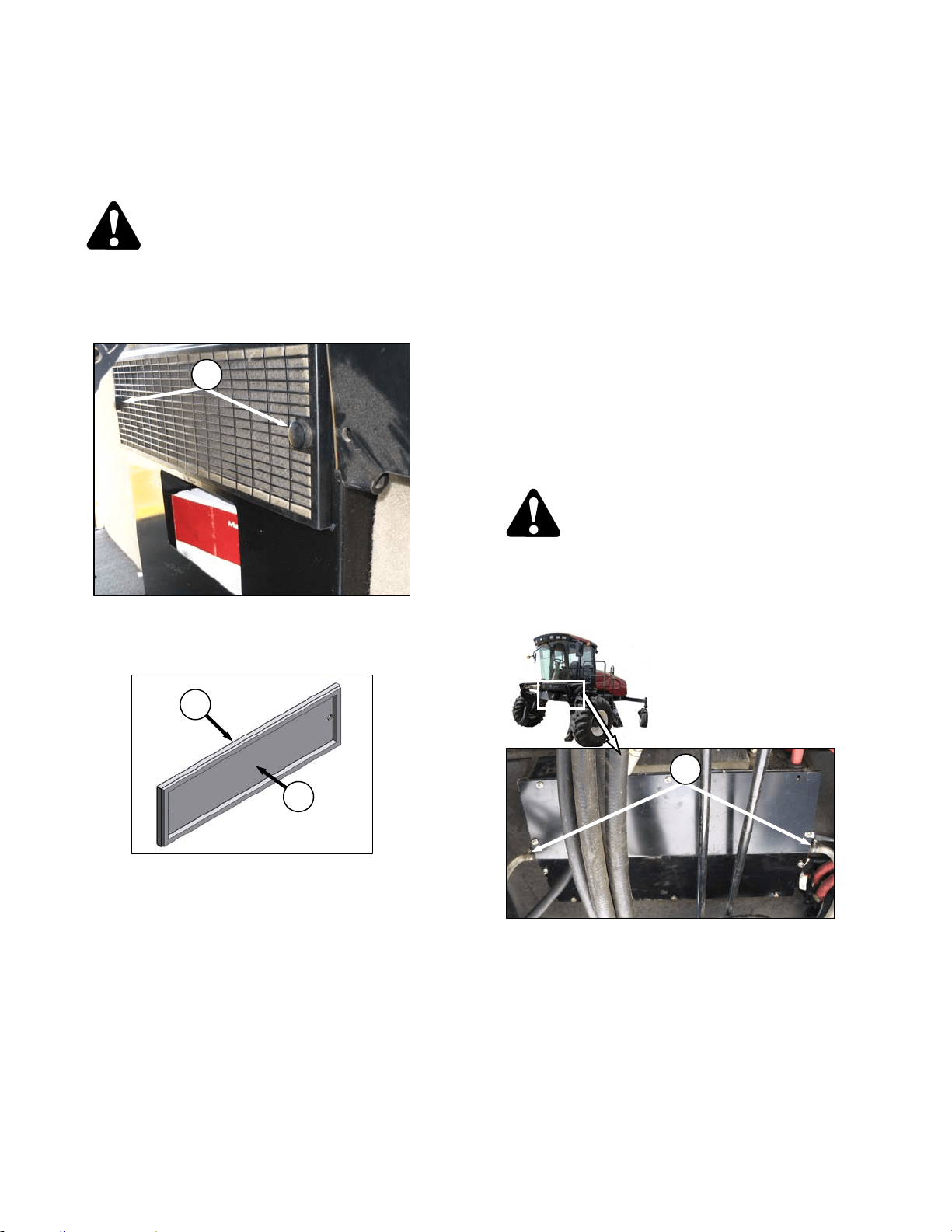
MAINTENANCE/SERVICE
169304 116 Rev. C
57.5.5.2 Return Air Cleaner
The return air filter is located behind the
operator’s seat on the cab wall and should be
serviced every 100 hours as follows:
DANGER
Stop engine and remove key from ignition
before leaving operator's seat for any
reason. A child or even a pet could engage
an idling machine.
a. Unscrew the two knobs (A) attaching cover and
filter to cab wall, and pull off the cover and filter
assembly.
b. Separate the filter (B) from the cover (C).
c. Clean the filter as follows:
1. Mix a solution of warm water and detergent
in a suitable container so that the filter can
soak for a few minutes.
2. Agitate to flush out the dirt.
3. Rinse with clean water and dry with
compressed air.
4. Inspect filter for damage, separation, and
holes. Replace if damaged.
d. Assemble the filter (B) and cover (C) and
position on cab wall over opening.
e. Secure to cab wall with knobs (A).
57.5.5.3 A/C Condenser
The air conditioning condenser should be
cleaned daily with compressed air and more
frequent cleaning may be necessary in severe
conditions. Cleaning the condenser can be
done at the same time as the radiator, oil cooler,
and charge air cooler. Refer to Section 7.9.2
Cooling Box Maintenance.
57.5.5.4 A/C Evaporator
The air conditioning evaporator should be
checked annually for cleanliness. If the air
conditioning system produces insufficient
cooling, a possible cause is clogged evaporator
fins. Fins will clog up from the side opposite the
blowers.
The evaporator is located inside the heating air
conditioning unit under the cab. To clean the
evaporator, proceed as follows:
DANGER
Stop engine and remove key from ignition
before leaving operator's seat for any
reason. A child or even a pet could engage
an idling machine
a. Loosen the clamps (D) on the two drain hoses
and pull the hoses off the air conditioning drain
tubes.
(continued next page)
D
C
B
A
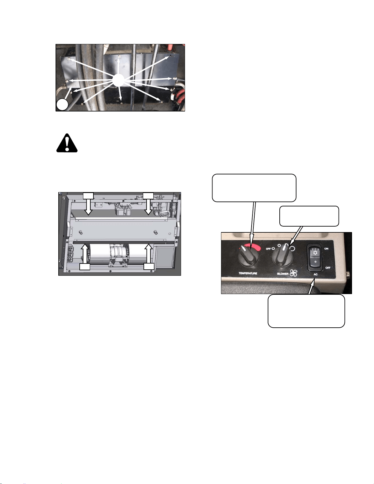
MAINTENANCE/SERVICE
169304 117 Rev. C
b. Remove the ten screws (H) that attach the cover
(J) and remove the cover.
WARNING
To avoid cuts from evaporator fins, do not
use bare hands to brush away clogs.
c. Use a vacuum or compressed air to remove dirt
from inside the unit.
d. Blow compressed air through the evaporator fins
from the blower side first as shown. Direct the
air straight into the evaporator to prevent fin
damage. A nozzle extension would make this
procedure easier.
e. Repeat the previous step from the side opposite
the blowers.
f. If dirt is still present, soak evaporator in water to
loosen dirt, and then blow out with compressed
air.
g. Straighten any bent fins.
h. Reposition cover (J) and attach with eight
screws (H).
i. Reattach drain hoses to drain tubes and secure
with hose clamps (G).
57.5.5.5 A/C Compressor Protection
The compressor is protected from excessively
low and high pressures by two switches that
shut down the compressor to prevent damage to
the system. These switches do not require any
regular servicing or maintenance, so if problems
occur and the switches are suspect, contact
your dealer.
57.5.5.6 Refrigerant and Oil
IMPORTANT
Perform the following steps whenever the
machine is first started after storage for
more than one week:
a. Ensure heater shut-off valve at engine is open.
See 5.10.3 Heater Shut-off Valve.
b. Turn blower switch to first position, turn
temperature control switch to maximum heating,
and A/C control to “OFF”.
c. Start engine and operate at low idle until engine
is warm.
d. Click A/C switch from "OFF" to "ON" for one
second, then back to "OFF" for 5 to 10 seconds.
Repeat this step ten times.
AIR
AIR
AIR
AIR
TEMPERATURE CONTROL
Controls Cab Temperature
INCREASE – Clockwise
DECREASE - Counter-Clockwise
BLOWER SWITCH
Controls Blower Speed
OFF/LO/MEDIUM/HI
AIR CONDITIONING SWITCH
Controls A/C System
OFF - A/C Does Not Operate.
ON - A/C Operates With Blower
Switch On.
H
J
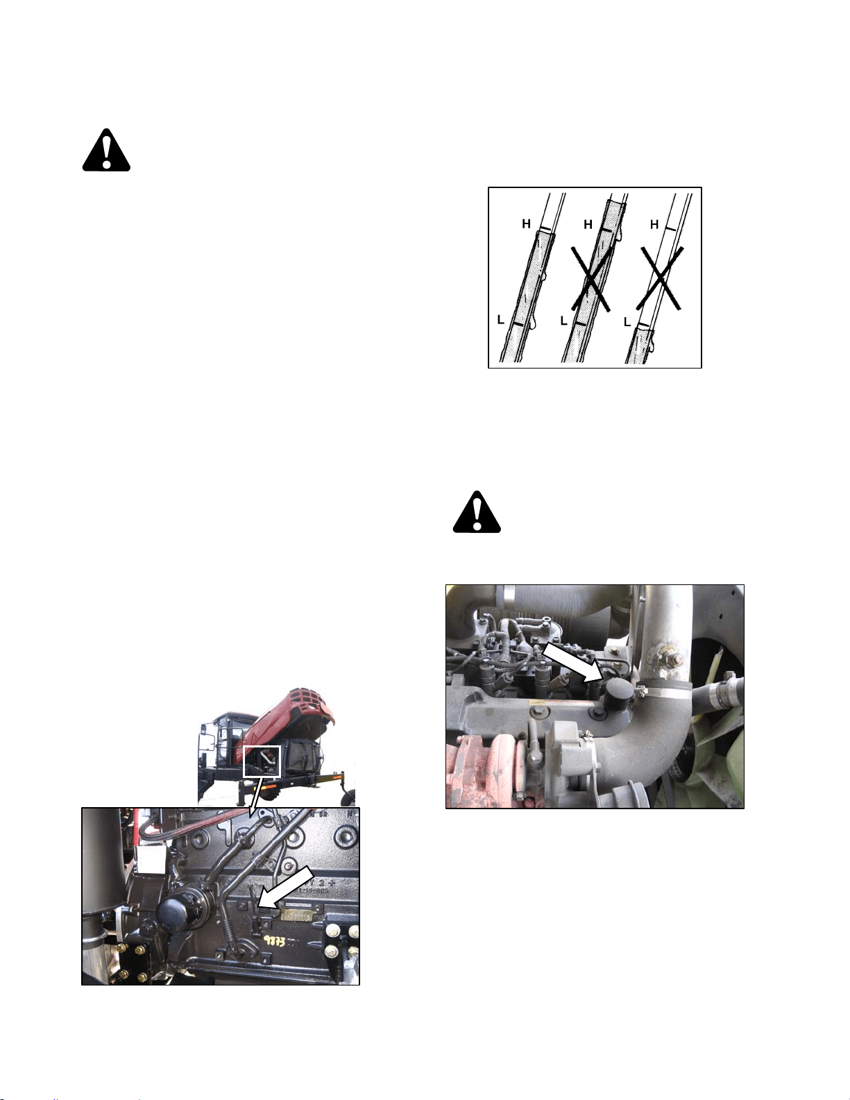
MAINTENANCE/SERVICE
169304 118 Rev. C
57.6 ENGINE
CAUTION
• Never operate engine in a closed
building. Proper ventilation is required to
avoid exhaust gas hazards.
• Keep the engine clean. Straw and chaff
on a hot engine are a fire hazard.
• Never use gasoline, naphtha or any other
volatile material for cleaning purposes.
These materials are toxic and/or
flammable.
57.6.1 General Engine Inspection
Have the overhead valve lash checked and
adjusted every 5000 hours or 4 years by your
Windrower dealer.
A general engine inspection, including the fuel
injection pump and nozzle inspection, is
recommended every 2000 hours. See your
dealer.
57.6.2 Oil Level
Check engine oil level frequently and watch for
any signs of leakage.
NOTE
During the break-in period, a higher than
usual oil consumption should be
considered normal.
a. Stop the engine and remove the key. Wait
about 5 minutes.
b. Open engine compartment hood to lowest
position.
c. Remove dipstick by turning it counterclockwise
to unlock and remove.
d. Wipe clean, reinsert in engine and remove.
e. Oil level should be between LOW and HIGH
marks.
f. Replace dipstick.
g. Add oil as follows if level is below the LOW
mark. One U.S. qt. (1 liter) will raise the level
from LOW to HIGH:
CAUTION
Do not fill above the HIGH mark.
1. Move platform to aft position.
2. Remove filler cap on top of engine.
3. Carefully pour the oil. Use SAE 15W40
Compliant With SAE Specs for API Class SJ
and CH-4 Engine Oil. A funnel is
recommended to avoid spillage.
4. Replace oil filler cap.
h. Close engine compartment hood.
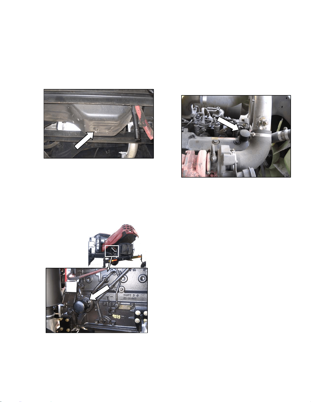
MAINTENANCE/SERVICE
169304 119 Rev. C
57.6.3 Changing Oil and Oil Filter
NOTE
The engine should be warm prior to
changing the oil.
a. Stop the engine and remove the key.
b. Place a drain pan of about 5 U.S. gallons (20
liters) under the engine oil drain.
c. Remove oil pan drain plug and allow the oil to
completely finish draining.
d. Check the condition of the used oil. If either of
the following is evident, have your dealer correct
the problem before starting the engine:
1. Thin black oil indicates fuel dilution.
2. Milky discoloration indicates coolant dilution.
e. Open engine compartment hood to lowest
position.
f. Clean around the filter head.
g. Remove filter.
h. Clean gasket mating surface.
i. Apply a thin film of clean oil to the gasket on the
new filter.
j. Screw the new filter onto the filter mount until
the gasket contacts the filter head.
k. Tighten the filter an additional ½ to ¾ turn by
hand.
IMPORTANT
Do not use a filter wrench to install the oil
filter. Over-tightening can damage the
gasket and filter.
l. Install the oil pan drain plug.
m. Remove oil filler pipe cap and add engine oil.
The engine requires 7.6 U.S. quarts (7 liters) of
SAE 15W40 Compliant with SAE Specs for API
Class SJ and CH-4 Engine Oil. Replace filler
pipe cap.
n. Operate the engine at low idle and check for
leaks at the filter and drain plug.
o. Stop the engine, wait 5 minutes and check the
oil level. Add or remove oil to bring oil to HIGH
level mark on dipstick.
p. Close engine compartment hood.
q. Properly dispose of used oil and filter.
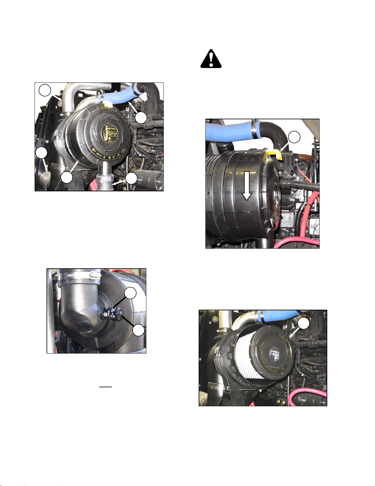
MAINTENANCE/SERVICE
169304 120 Rev. C
57.6.4 Air Intake System
IMPORTANT
Do not run engine with air cleaner
disconnected or disassembled.
Engine intake air (A) is drawn through a duct (B)
from the cooling box that pre-cleans the air, then
through a dual element filter (C) to the turbo-
charger intake (D). The charged air then passes
through a cooler and into the engine. The air
cleaner canister is equipped with a vacuator
valve (E) that removes dust continuously from
the air cleaner housing.
57.6.4.1 Restriction Gauge
The air cleaner is also equipped with a
mechanical sensor (F) which indicates red when
the primary filter element requires servicing.
a. Check restriction gauge daily
.
b. After servicing, re-set restriction gauge by
pushing button (G) on top of gauge.
NOTE
Only service filter element when restriction
gauge indicates red. Over-servicing the filter
element increases the risk of dirt being ingested
by the engine, and severely damaging the
engine.
57.6.4.2 Air Filter Servicing
DANGER
Stop engine and remove key from ignition
before leaving operator's seat for any
reason. A child or even a pet could engage
an idling machine.
a. Open engine compartment hood to highest
position.
b. Slide yellow locking tab (H) to release canister
end cap and rotate end cap counterclockwise
until it stops.
c. Pull off end cap.
d. Check the vacuator valve (E) daily for
obstructions or damage. Clean or replace if
necessary.
e. Pull out the primary filter element (J) and inspect
as follows:
(continued next page)
A
B
C
E
D
H
J
F
G
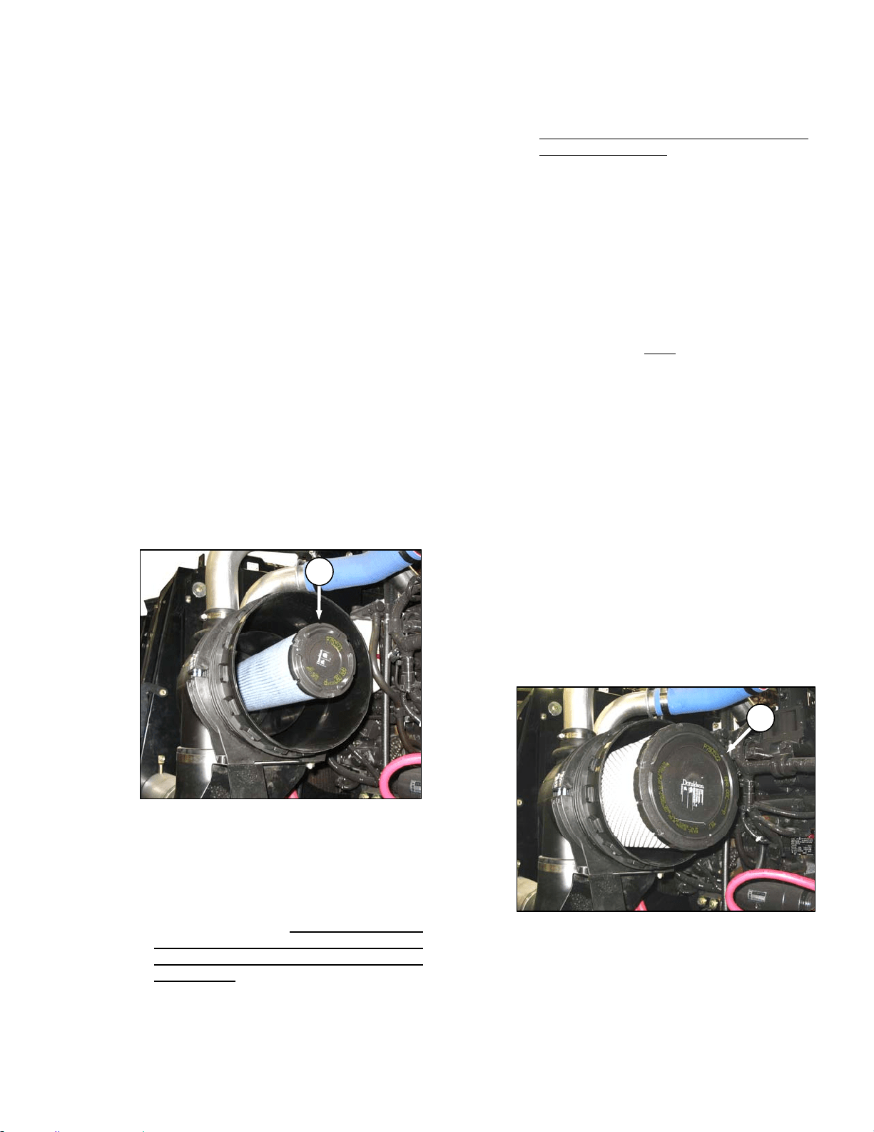
MAINTENANCE/SERVICE
169304 121 Rev. C
IMPORTANT
Air filter element cleaning is not
recommended due to the possible
degradation of the element material. If
cleaning is performed, there are several
risks involved, and the following
procedures should be followed:
1. Hold a bright light inside element and check
carefully for holes. Discard any element
which shows the slightest hole.
2. Be sure outer screen is not dented. Vibration
would quickly wear a hole in the filter.
3. Be sure filter gasket is in good condition. If
gasket is damaged or missing, replace
element.
4. If element is coated with oil or soot, replace
the element.
f. Inspect the air intake piping for damage, cracked
hoses, loose clamps, etc. Repair or replace
damaged parts and tighten loose clamps.
IMPORTANT
Do not remove the secondary filter
element (K) unless it needs replacing. Do
not attempt to clean the secondary (inner)
element.
g. Check the secondary element (K) for
cleanliness. If there is visible dirt on the
secondary element, replace both primary and
secondary elements.
IMPORTANT
The air cleaner's primary (outer) filter
element should be replaced after three
cleanings or at the specified interval.
Refer to Section 7.13 MAINTENANCE
SCHEDULE.
IMPORTANT
The secondary (inner) element should be
replaced every third time the primary
element is changed.
h. Clean inside of canister and cover with a damp
cloth.
IMPORTANT
Leave secondary element in place to
prevent ingress of dirt into engine intake.
i. Pat sides of primary element gently to loosen
dirt. Do not tap element against a hard surface.
j. Using a Dry Element Cleaner Gun, clean
element with compressed air.
k. Hold nozzle next to inner
surface, and move up
and down pleats.
IMPORTANT
Air pressure must not exceed 60 psi (414
kPa). Do not direct air against outside of
element, as dirt might be forced through to
inside.
l. Repeat steps h. and i. to remove additional dirt.
m. Repeat inspection before installing.
n. To remove the secondary element (K), pull it out
of the canister.
o. Insert secondary filter element into canister,
seal first, and push until seal is seated inside
canister.
IMPORTANT
When replacing secondary filter, reinsert
new filter as soon as possible to prevent
dirt entering engine intake
p. Insert primary filter element (J) into canister over
secondary element and push into place,
ensuring that element is firmly seated in
canister.
K
J
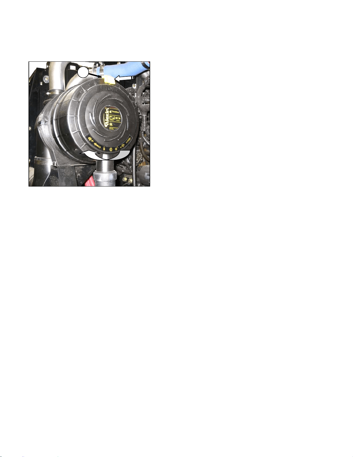
MAINTENANCE/SERVICE
169304 122 Rev. C
q. Position end cap onto filter housing with
vacuator valve pointing approximately down.
r. Rotate end cap clockwise until it stops.
s. Slide yellow locking tab (H) to lock end cap in
place.
t. Close engine compartment hood.
57.6.4.3 Charge Air Cooling
After the intake air passes through the air filter, it
passes through the turbocharger which boosts
the pressure. This process heats the air so it is
passed through a cooler before entering the
engine intake. The cooler is located in the
cooling box behind the radiator and should be
cleaned daily with compressed air. Refer to
Section 7.9.2, Cooling Box Maintenance.
H
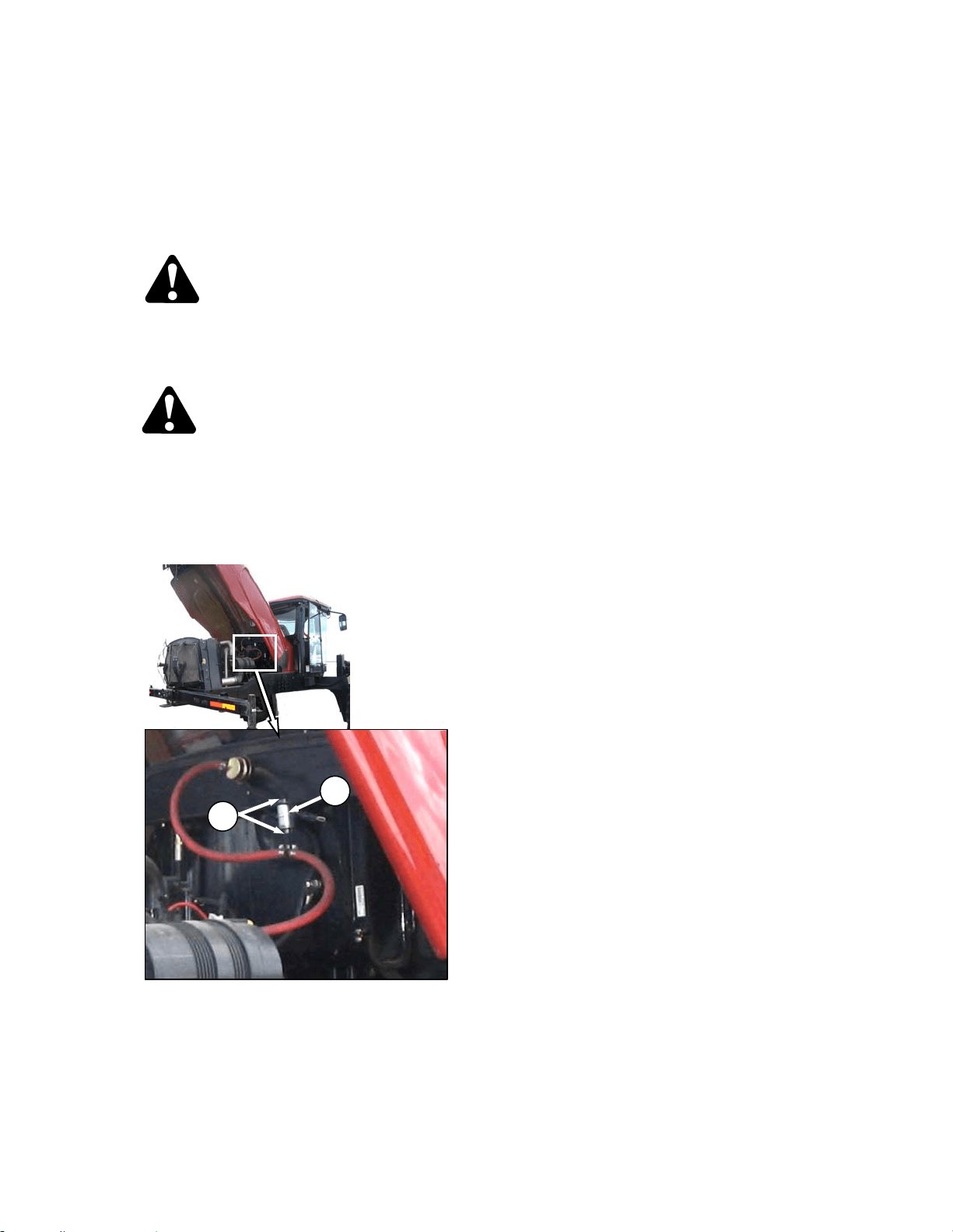
MAINTENANCE/SERVICE
169304 123 Rev. C
57.6.5 Fuel System
57.6.5.1 Fuel Tank Venting
The fuel tank is vented by a hose that is
connected to the filler tube. The hose is
connected to a filter that should be changed
annually. Change the filter as follows:
DANGER
Stop engine and remove key from ignition
before leaving operator's seat for any
reason. A child or even a pet could engage
an idling machine.
WARNING
To avoid personal injury or death from
explosion or fire, do not smoke or allow
flame or sparks near windrower when
servicing.
a. Open engine compartment hood to highest
position.
b. Locate filter (A) on vent line against hydraulic oil
reservoir.
c. Release hose tension clamps (B) and slide away
from filter. Pull hoses off filter.
d. Position new filter through hole in frame and
attach top hose onto filter. “IN” marking should
face down.
NOTE
If filter has an arrow instead of an IN
marking, arrow should point up.
e. Attach lower hose to filter and secure both
hoses with tension clamps (B).
B
A
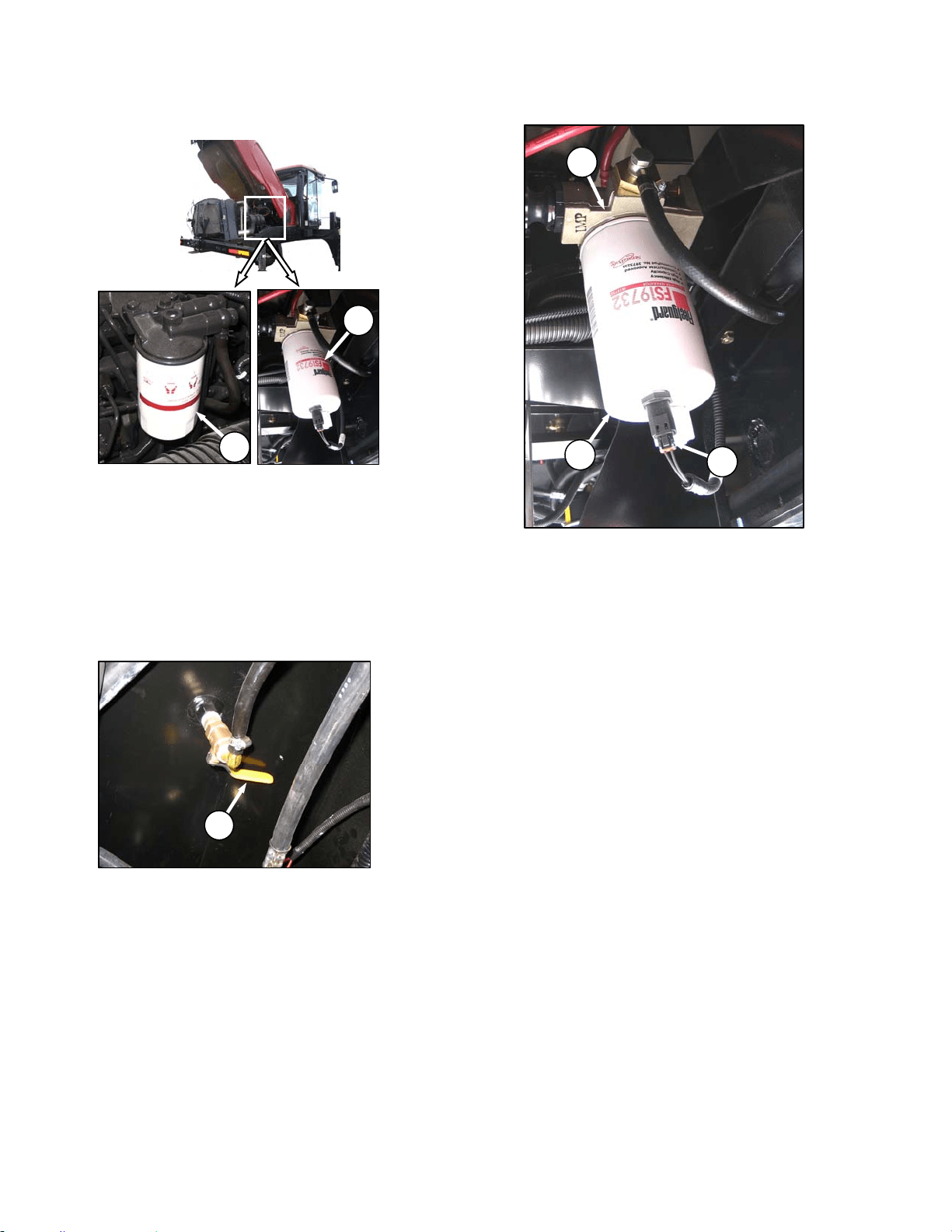
MAINTENANCE/SERVICE
169304 124 Rev. C
57.6.5.2 Fuel Filters
The M100 windrower fuel system is equipped
with primary (C) and secondary (D) filters. Both
filters are screw-on cartridge type but the
primary (C) filter is equipped with a separator
that separates sediment and water from the fuel.
Change both filters as follows every 500 hours
of operation:
a. Open engine compartment hood to highest
position.
b. Close fuel supply valve (E) under fuel tank.
c. Change primary filter (C) as follows:
1. Clean around the filter head (F).
2. Disconnect Water in Fuel (WIF) sensor (G)
from bottom of filter.
3. Remove filter (C) with a filter wrench.
4. Clean gasket mating surface.
5. Fill new filter with clean fuel and apply a thin
film of clean oil to the gasket on the new
filter.
6. Screw the new filter (C) onto the filter mount
until the gasket contacts the filter head.
7. Reconnect WIF sensor (G).
8. Tighten the filter an additional ½ to ¾ turn by
hand.
IMPORTANT
Do not use a filter wrench to install the
filter. Over-tightening can damage the
gasket and filter.
(continued next page)
E
D
C
C
F
G
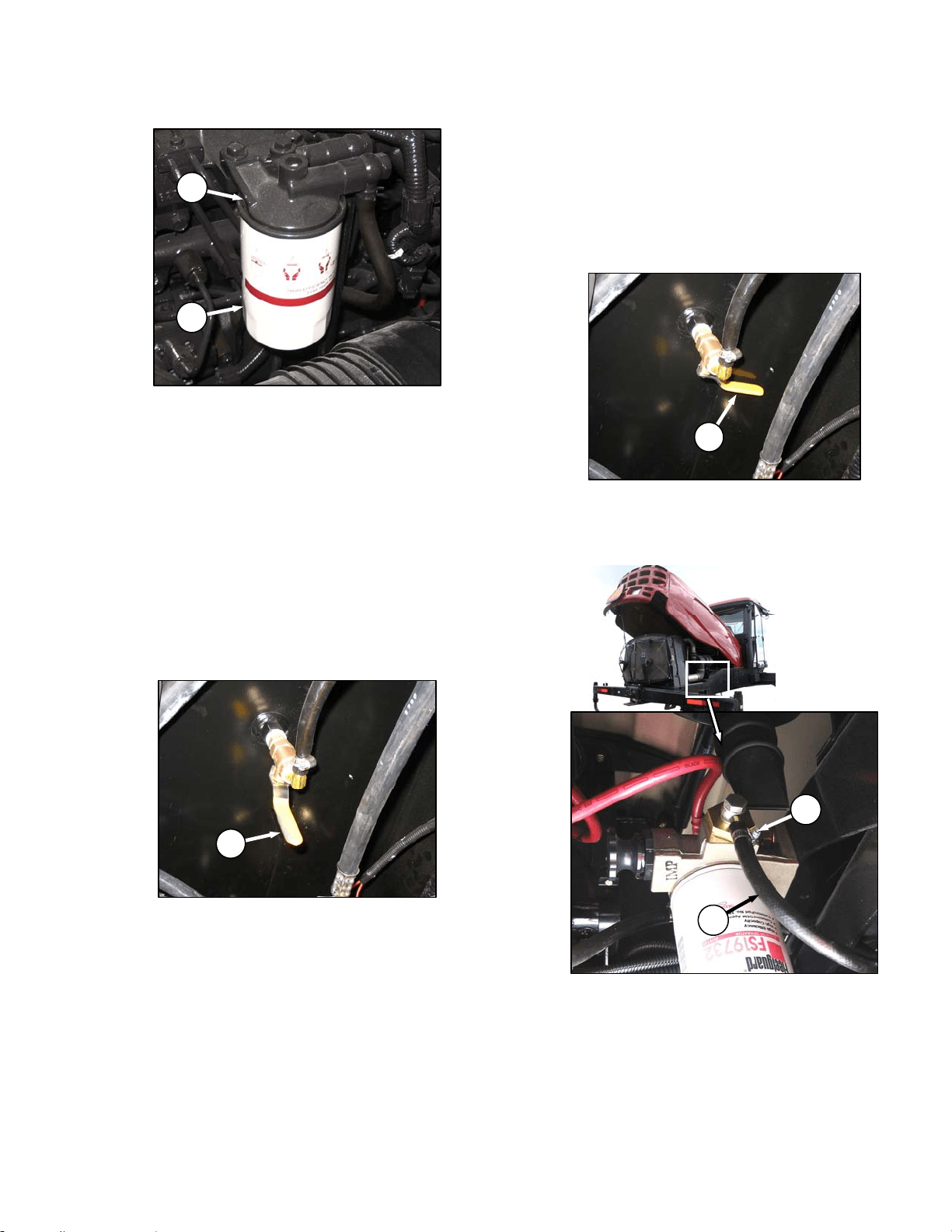
MAINTENANCE/SERVICE
169304 125 Rev. C
d. Change secondary filter (D) as follows:
1. Clean around the filter head (H).
2. Remove filter (D) with a filter wrench.
3. Clean gasket mating surface.
4. Apply a thin film of clean oil to the gasket on
the new filter.
5. Screw the new filter onto the filter mount
until the gasket contacts the filter head.
6. Tighten the filter an additional ½ to ¾ turn by
hand.
IMPORTANT
Do not use a filter wrench to install the
filter. Over-tightening can damage the
gasket and filter.
e. Open fuel valve (E) under fuel tank.
f. Use priming pump on primary filter to fill new
filter.
g. Close engine compartment hood.
57.6.5.3 Draining Fuel Tank
Draining the fuel tank is necessary to remove
old or contaminated fuel. To drain the tank refer
to following illustrations and proceed as follows:
a. Stop the engine and remove the key.
b. Open engine compartment hood to lowest
position.
c. Close fuel supply valve (E).
d. Place a drain pan of about 5 U.S. gallons (20
liters) under the fuel supply line (J).
e. Loosen clamp (K) and pull hose (J) off fitting.
f. Route hose to drain pan and open valve (E) to
drain tank.
(continued next page)
E
E
J
K
H
D
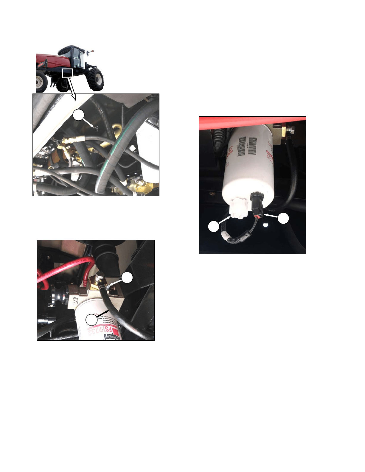
MAINTENANCE/SERVICE
169304 126 Rev. C
g. Remove plug (L) to ensure tank is completely
drained after fuel has stopped flowing from
hose.
h. Add some clean fuel to tank to flush out any
remaining contaminants.
i. Replace drain plug and reattach hose (J) to
fitting. Install clamp (K) and tighten.
j. Refill tank.
57.6.5.4 Separator
A fuel water separator is incorporated into the
primary fuel filter. The separator is equipped
with a sensor (G) that detects water in the fuel
and alerts the operator on the CDM. Drain the
water and sediment as follows from the
separator daily or at any time the CDM Water in
Fuel (WIF) light illuminates.
a. Stop engine and remove key.
b. Turn drain valve (M) by hand 1½ to 2 turns
counterclockwise until draining occurs.
c. Drain the filter sump of water and sediment until
clear fuel is visible.
d. Turn the valve clockwise to close the drain.
L
G
M
J
K
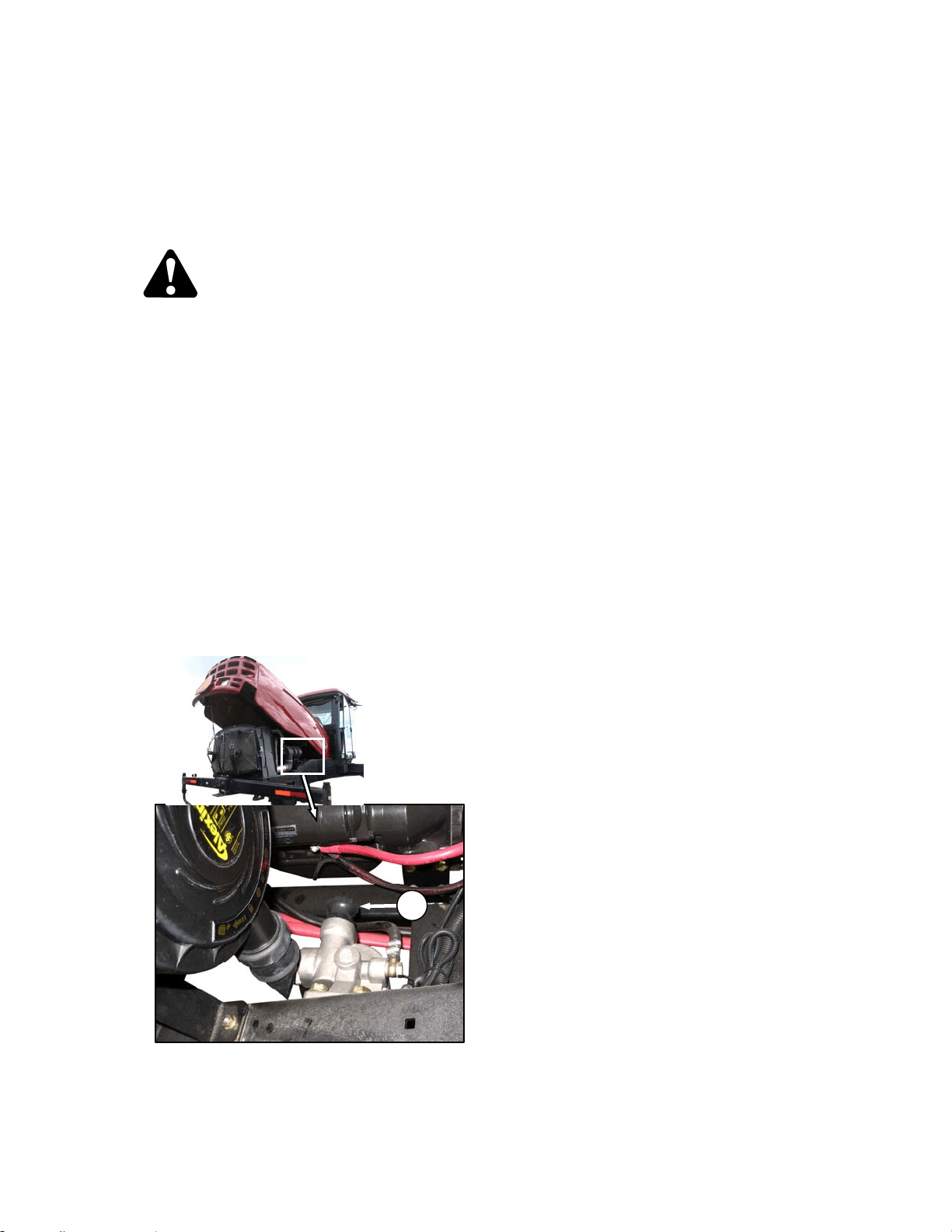
MAINTENANCE/SERVICE
169304 127 Rev. C
57.6.5.5 System Priming
Controlled venting of air is provided at the
injection pump through the fuel drain manifold.
Small amounts of air introduced by changing
filters or injection pump supply line will be
vented automatically, if the fuel filters are
changed in accordance with instructions.
WARNING
The fuel pump high-pressure fuel lines and
fuel rail contain extremely high pressure fuel.
Never loosen any fittings. Personal injury
and property damage can result.
IMPORTANT
Bleeding the fuel system is not
recommended nor required.
a. Manual priming may be required if:
• The fuel filter is not filled prior to installation.
• Injection pump is replaced.
• High-pressure fuel lines are replaced.
• Engine is run until fuel tank is empty.
b. Prime the fuel system as follows:
1. Stop the engine and remove the key.
2. Open engine compartment hood to lowest
position.
3. Turn the priming knob (A) counterclockwise
to unlock the plunger on the primary filter
head.
4. Pump approximately 120 times to pressurize
the fuel system.
5. Lock the plunger by turning knob (A)
clockwise until snug.
A
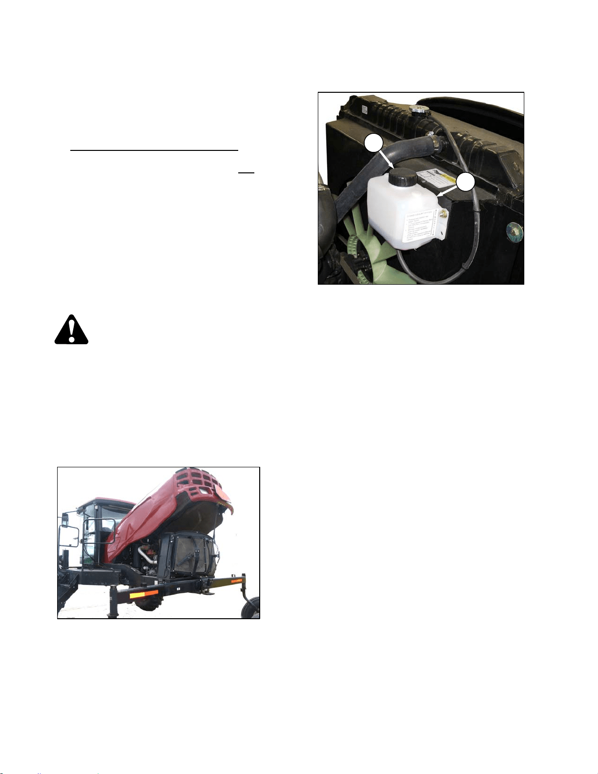
MAINTENANCE/SERVICE
169304 128 Rev. C
57.6.6 Engine Cooling System
The engine cooling system is designed to
maintain the engine operating temperature
within the specified operating range.
NOTE
Anti-freeze is essential in any climate
. It
broadens the operating temperature range
by lowering the coolant freezing point and
by raising its boiling point. Anti-freeze
also contains rust inhibitors and other
additives to prolong engine life.
IMPORTANT
If anti-freeze strength is not adequate, do
not drain cooling system to protect against
freezing. System may not drain
completely, and damage from freezing
could still result.
To service the cooling system, perform the
following:
DANGER
Stop engine and remove key from ignition
before leaving operator's seat for any
reason. A child or even a pet could engage
an idling machine.
a. Stop engine and remove key.
b. Move the maintenance platform to the open
position for access to the coolant tank and
radiator. Ensure the platform latch is engaged in
open position.
c. Raise engine compartment hood to lowest
position.
57.6.6.1 Coolant Level and Concentration
a. Check daily the coolant level in the coolant
recovery tank (A). Tank should be at least half
full.
b. If less, then remove cap (B) and add coolant.
Use Ethylene Glycol with SCA and equal parts
of high quality, soft, de-ionized, or distilled water
as recommended by the supplier to protect the
engine to temperatures of -30°F (-34°C).
NOTE
Do not add coolant to radiator except
when changing coolant.
c. Replace cap (B).
B
A
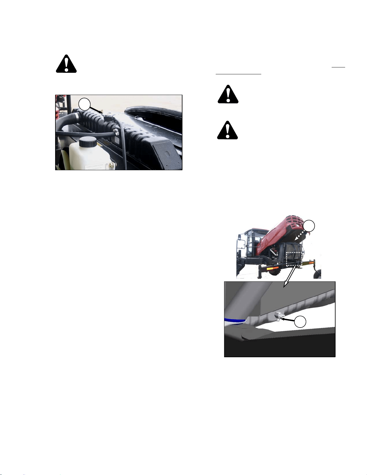
MAINTENANCE/SERVICE
169304 129 Rev. C
57.6.6.2 Radiator Cap
CAUTION
To avoid personal injury from hot coolant, do
not turn radiator cap until engine has cooled.
a. Remove the radiator cap (C) and check as
follows:
1. The radiator cap must fit tightly.
NOTE
Cap gasket must be in good condition to
maintain the 14-18 psi (97-124 kPa)
pressure in the cooling system. To check
the cap, proceed as follows:
2. Turn the cap counterclockwise to the first
notch to relieve pressure before removing
cap completely.
3. Turn the cap again and remove.
4. Check the gasket for cracks or deterioration
and replace the cap if necessary.
5. Check that the spring in the cap moves
freely.
6. Check the anti-freeze in the radiator with a
tester annually, preferably before off-season
storage. Tester should indicate protection to
temperatures of -30°F (-34°C).
b. Replace the cap if spring is stuck.
c. Close engine compartment hood and move
maintenance platform to working position.
57.6.6.3 Changing Coolant
Coolant should be drained, and the system
flushed and filled with new coolant every 2000
hours or 2 years. Change coolant, and flush the
system as follows:
CAUTION
To avoid personal injury from hot coolant, do
not turn radiator cap until engine cools.
DANGER
Stop engine and remove key from ignition
before leaving operator's seat for any
reason. A child or even a pet could engage
an idling machine.
a. Stop engine and let it cool.
b. Move the maintenance platform toward the rear
of the windrower. Ensure the lock is engaged.
c. Raise engine compartment hood to lowest
position.
d. Turn the radiator cap (C) to the first notch to
relieve pressure before removing cap
completely.
e. Place a drain pan (about 8 U.S. gallons (30
liters)) under the engine and radiator.
f. Remove the radiator cap and open radiator drain
valve (D) on the engine side of the radiator lower
tank. Use a deflector or a hose to prevent
coolant running onto frame.
(continued next page)
C
C
D
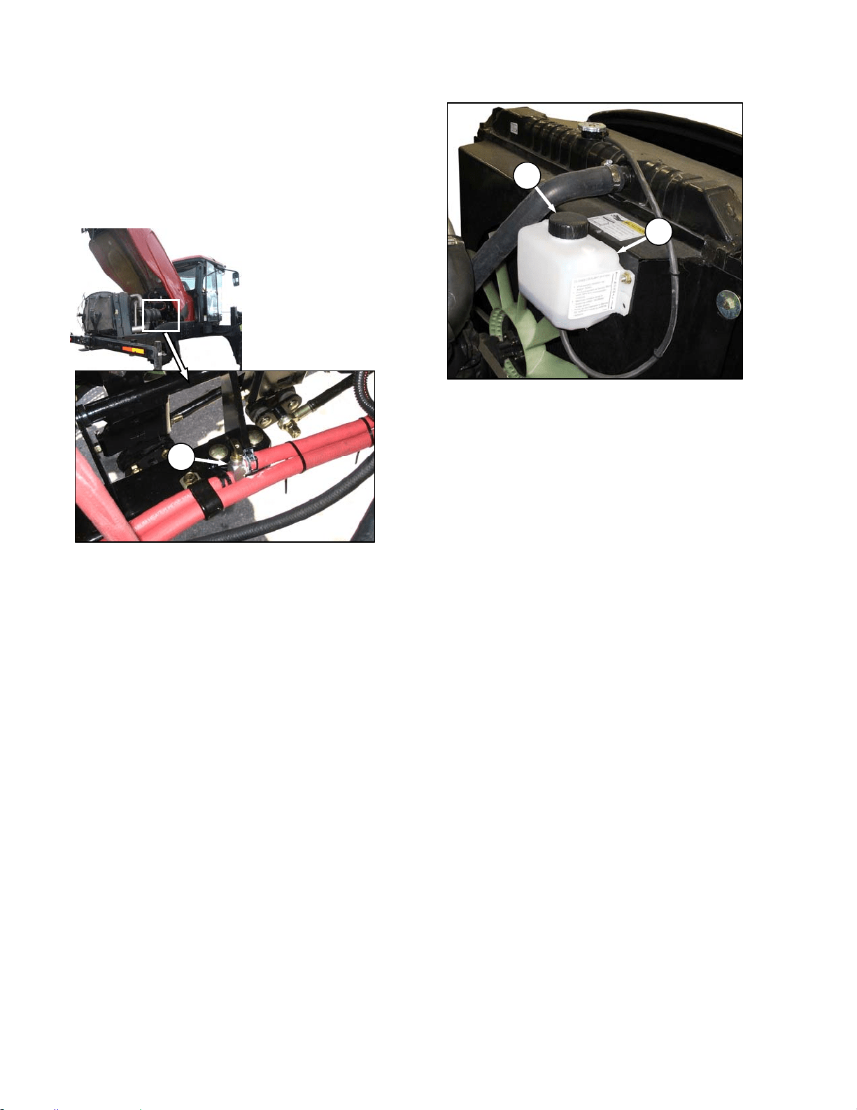
MAINTENANCE/SERVICE
169304 130 Rev. C
g. Loosen drain plug in engine block so that
coolant drains.
h. When system is drained, replace drain plug in
block and close radiator drain valve (D).
i. Fill system with clean water through the radiator
and replace radiator cap.
j. Open heater shut-off valve (E).
k. Start engine and turn temperature control knob
to high. Run engine until normal operating
temperature is reached.
l. Stop engine and drain water out before rust or
sediment settles. See steps d. to g.
m. Close drain valves and fill system with a solution
of clean water and a heavy duty radiator
cleaner. Follow instructions provided with
cleaner.
n. After using cleaner solution, again flush system
with clean water. Inspect radiator, hoses and
fittings for leaks.
o. Close drain valves and fill system through
radiator with an equal part mix of anti-freeze and
clean, soft water. Use Ethylene Glycol with SCA
and equal parts of high quality, soft, de-ionized,
or distilled water as recommended by the
supplier to protect the engine to temperatures of
-30°F (-34°C). System capacity is 5.3 U.S.
Gallons (20 liters).
p. Close radiator cap tightly.
q. Remove cap (B) from recovery tank (A) and add
coolant until half full.
r. Move maintenance platform to working position
and close engine compartment hood.
E
B
A
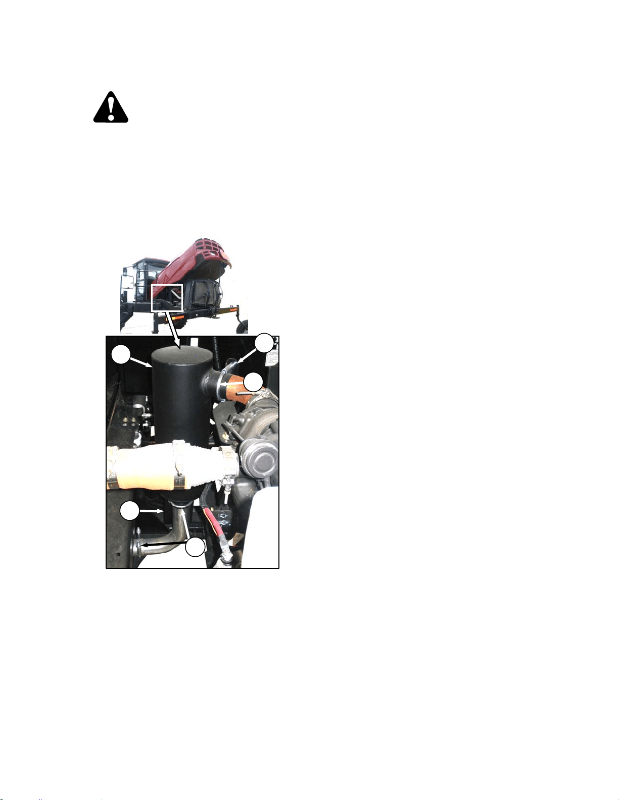
MAINTENANCE/SERVICE
169304 131 Rev. C
57.6.7 Exhaust System
CAUTION
To avoid burns, do not touch muffler when
engine is running or before allowing
sufficient cooling time after shut-down
The exhaust system requires no regular
maintenance but it should be inspected
periodically as follows:
a. Open engine compartment hood to highest
position.
b. Inspect the area around clamps (A) for
breakage, cracks and rust-through. In addition
to excess noise, a leaky exhaust system may
allow exhaust gases to escape to the cab.
c. Dents or crushed portions of any tubing create
exhaust flow restriction and increase back
pressure significantly. Even relatively small
dents will cause decreased fuel economy and
increased turbo wear. If dents are relatively
large, increased bearing and cylinder wear will
occur due to increased exhaust temperature.
d. The exhaust system should be secured to
eliminate vibration. The brackets (B) should fit
securely to the muffler (C) and to the engine.
e. Do not change muffler type, piping sizes or
exhaust configuration; these have all been
selected for some very specific, technical
reasons by the engineer. See your dealer for
proper replacement parts.
B
C
B
A
A
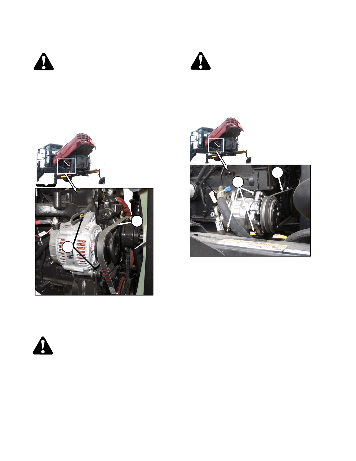
MAINTENANCE/SERVICE
169304 132 Rev. C
57.6.8 Belts
DANGER
Stop engine and remove key from ignition
before leaving operator's seat for any
reason. A child or even a pet could engage
an idling machine.
57.6.8.1 Fan Belt Tension
a. Shutdown engine and open engine compartment
access hood to lowest position.
b. Loosen alternator mounting hardware (A).
c. Pry alternator away from engine so that a force
of 22 lbf (100 N) deflects belt (B) 5/16 to 1/2 inch
(8 to 12 mm) at mid-span between fan pulley
and alternator.
CAUTION
Overtightening the belt will result in
alternator damage.
d. Tighten alternator mounting hardware (A).
e. Recheck tension and re-adjust as required.
57.6.8.2 Fan Belt Replacement
DANGER
Stop engine and remove key from ignition
before leaving operator's seat for any
reason. A child or even a pet could engage
an idling machine.
a. Shutdown the engine and open engine
compartment access hood to highest position.
b. Loosen compressor mounting hardware (C) and
push compressor towards engine to release belt
(D) tension.
c. Remove belt (D).
d. Loosen alternator mounting hardware (A) and
push alternator towards engine to release belt
(B) tension.
e. Remove belt (B).
f. Install new belt (B) on pulleys.
g. Pry alternator away from engine so that a force
of 22 lbf (100 N) deflects belt (B) 5/16 to 1/2 inch
(8 to 12 mm) at mid-span between fan pulley
and compressor.
h. Tighten alternator mounting hardware (A).
i. Recheck tension and re-adjust as required.
j. Install A/C compressor belt (D) on pulleys.
k. Pry compressor away from engine so that a
force of 8 to 12 lbf (35-55 N) deflects the belt (D)
3/16 inch (5 mm) at mid-span.
l. Tighten compressor mounting hardware (C).
m. Recheck tension and re-adjust as required.
n. Close engine compartment hood.
B
A
C
D
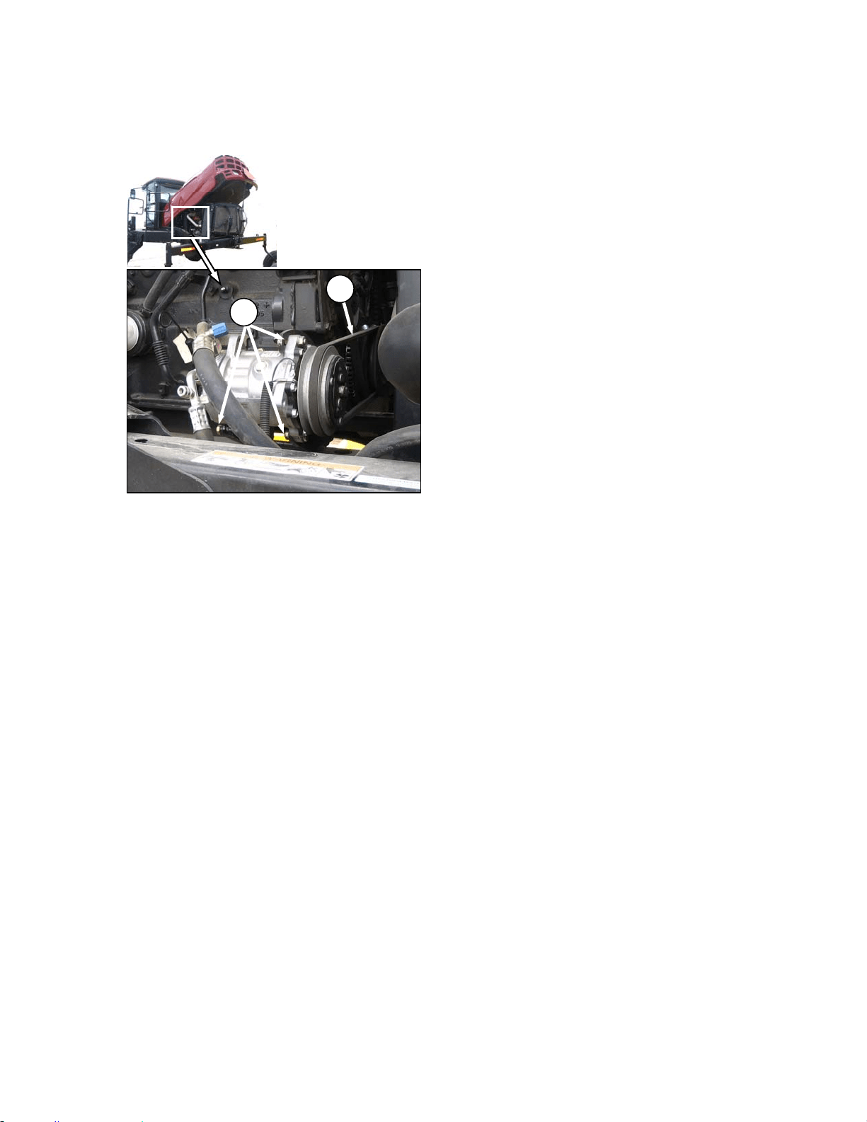
MAINTENANCE/SERVICE
169304 133 Rev. C
57.6.8.3 A/C Compressor Belt Tension
a. Shutdown engine and open engine compartment
access hood to lowest position.
b. Loosen compressor mounting hardware (A).
c. Pry compressor away from engine so that a
force of 8 to 12 lbf (35-55 N) deflects the belt (B)
3/16 inch (5 mm) at mid-span.
d. Tighten compressor mounting hardware (A).
e. Recheck tension and re-adjust as required.
f. Close engine compartment hood.
57.6.8.4 A/C Compressor Belt Replacement
a. Shutdown the engine and open engine
compartment access hood to lowest level.
b. Loosen compressor mounting hardware (A) and
push compressor towards engine to release
tension.
c. Remove belt (B).
d. Install new belt (B) on pulleys.
e. Pry compressor away from engine so that a
force of 8 to 12 lbf (35-55 N) deflects the belt (B)
3/16 inch (5 mm) at mid-span.
f. Tighten compressor mounting hardware (A).
g. Recheck tension and re-adjust as required.
h. Re-adjust tension of a new belt after a short run-
in period (about 5 hours).
57.6.9 Engine Speed
The maximum and idle engine speeds are
determined by the ECM software, and factory
set. See Section 4 Specifications. If specified
speeds cannot be maintained, see your
Windrower dealer.
57.6.9.1 Intermediate Engine Speeds
The engine operating speed can be
programmed to enable the windrower to operate
at reduced engine rpm without significantly
affecting the ground or header speeds.
Intermediate Speed Control (ISC) is useful in
where operating loads are reduced such as in
light crop conditions which do not require the
maximum engine rpm. Reduced engine speed
lowers fuel consumption, noise levels, and
exhaust emissions in addition to reducing engine
wear.
ISC Off (Normal) – 2600 rpm.
ISC On (Intermediate) – 2400 rpm.
Programming instructions are given in Section
5.18.5 Cab Display Monitor (CDM)
Programming. The programmed engine speed
is activated when the header is engaged.
57.6.9.2 Throttle Adjustment
The engine speed is controlled with the throttle
lever that is connected to an electronic sensor
inside the console. The throttle lever in the cab
should move the throttle sensor the full range
between slow speed stop and full RPM stop
without contacting the console at either position.
If the throttle lever is contacting the console and
interferes with specified engine speeds, the
sensor position possibly requires adjustment.
See your Windrower dealer.
A
B
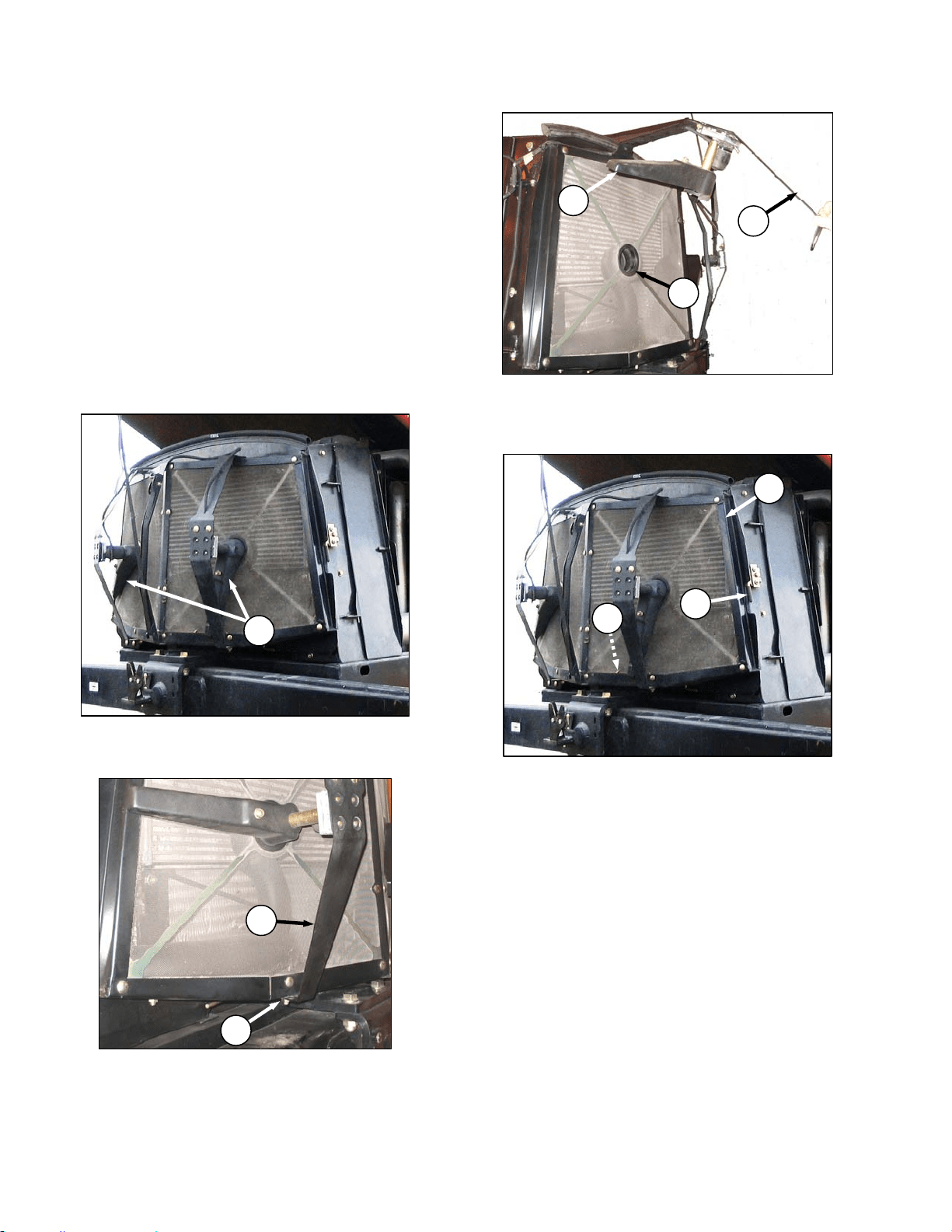
MAINTENANCE/SERVICE
169304 134 Rev. C
57.7 COOLING BOX
57.7.1 Cooling Box Screen Cleaners
The cooling box screen is equipped with an
automatic cleaning device which "vacuums" the
screen by means of two rotors. They only
operate when the key is on. The rotors are
electrically driven and the suction is provided by
the engine cooling fan.
If the screen is not being cleaned by the rotors,
they may be plugged. Service rotors and screen
as follows:
a. Stop engine and remove key.
b. Raise engine compartment hood fully.
c. If rotors (A) are plugged, clean as follows:
1. Remove nut (B).
2. Pivot rotor assembly (C) away from screen.
3. Blow out debris from rotors (A) with
compressed air.
d. Push latch (D) and open screen assembly
access door (E). Secure with rod (F) stored
inside screen door.
e. If duct (G) is plugged, blow out debris with
compressed air.
f. Clean screen with compressed air.
g. Reposition rotor assembly (C) secure with bolt
and nut (B).
h. Check clearance between trailing edge of
cleaner ducts (A). It should be .04-.32 inches
(1-8 mm) at all locations when rotating.
NOTE
Cleaner duct may touch screen as long as
duct continues to rotate.
(continued next page)
D
E
F
A
B
C
C
A
G
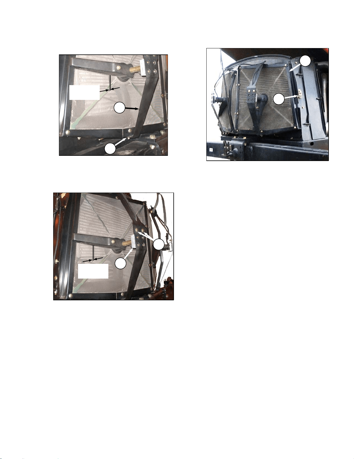
MAINTENANCE/SERVICE
169304 135 Rev. C
i. If necessary, adjust clearance as follows:
1. Loosen nut (B) on motor support (C).
2. Move support in or out until duct is 0.08-0.24
in. (2-6 mm) from screen near the center.
3. Re-tighten nut (B).
4. Loosen the two motor mount bolts (H).
5. Move motor/ duct assembly (J) to obtain
0.04-0.32 in. (1-8 mm) gap to screen at full
rotation of the duct.
6. Re-tighten nuts (H) on motor mount.
j. Close screen access door (E) and engage latch
(D).
k. Lower engine compartment hood.
B
C
0.08-0.24 in.
(
2-6 mm
)
D
E
H
J
0.04-0.32 in.
(1-8 mm)
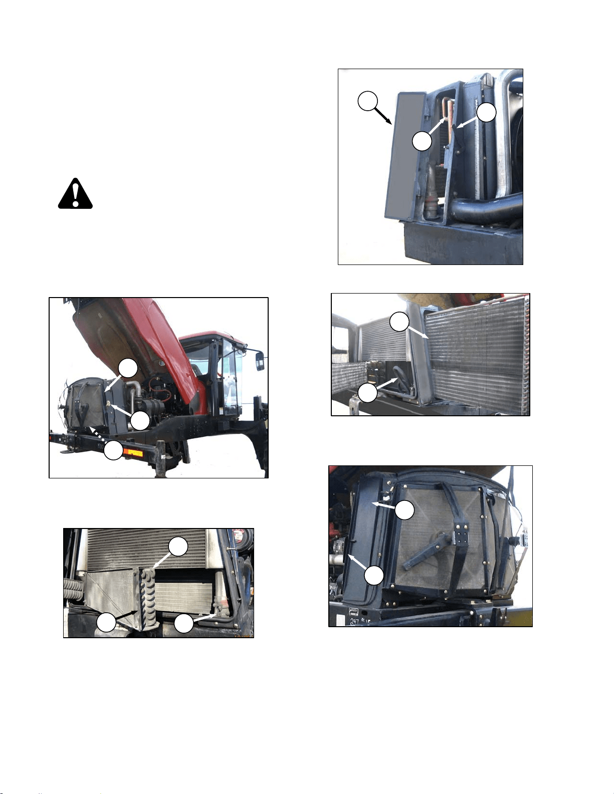
MAINTENANCE/SERVICE
169304 136 Rev. C
57.7.2 Cooling Box Maintenance
The radiator and oil cooler should be cleaned
daily with compressed air and more frequent
cleaning may be necessary in severe conditions.
The charge air cooler and air conditioning
condenser may also be cleaned at the same
time. To clean these components, refer to
illustrations below and proceed as follows:
DANGER
Stop engine and remove key from ignition
before leaving operator's seat for any
reason. A child or even a pet could engage
an idling machine.
a. Stop engine and remove key.
b. Raise engine compartment hood fully.
c. Push latch (A) and open screen assembly
access door (B). Secure with rod (C) stored
inside the screen door.
d. Rotate retainer (D), pull open condenser (E),
and secure with support rod at (F).
e. Lift lever (G) and pull open access door (J).
f. Slide out the oil cooler assembly (K) with handle.
If movement is restricted by hose (L), lift up on
hose so that it moves away from frame.
g. Lift latch (M) and open access door (N) on the
cooling box.
IMPORTANT
Fins on coolers can be very easily bent
which may interfere with its function.
Exercise caution when cleaning.
(continued next page)
L
K
D
E
F
A
B
C
K
J
G
N
M
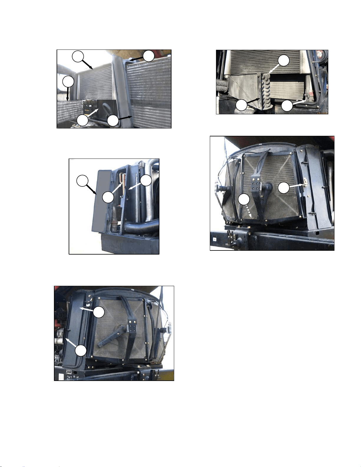
MAINTENANCE/SERVICE
169304 137 Rev. C
h. Clean radiator (O), oil cooler (K), charge air
cooler (P), air conditioning condenser (E) and
cooling box (Q) with compressed air.
i. Slide oil cooler (K) back into cooling box.
j. Close side access door (J) and lock with lever
(G).
k. Close side door (N) and secure with latch (M).
l. Remove support rod at (F), swing condenser (E)
back into position and secure with retainer (D).
m. Unhook support rod (C) in screen door and store
at base of cooling box.
n. Close door until latch engages pin (A).
o. Lower hood and hood latch will lock hood.
E
O
P
Q
K
K
J
G
A
C
N
M
D
E
F
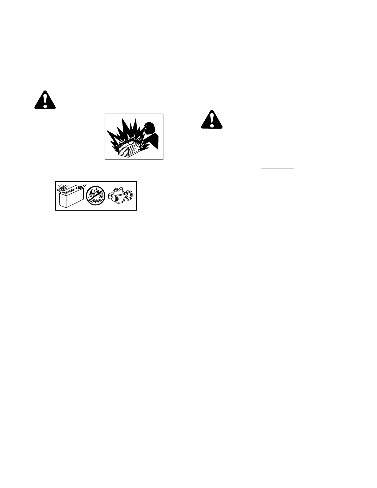
MAINTENANCE/SERVICE
169304 138 Rev. C
57.8 ELECTRICAL SYSTEM
Electrical schematics are attached at the back of
this manual.
57.8.1 Battery
WARNING
• Gas given off by
battery electrolyte
is explosive. Keep
all smoking
materials, sparks
and flames away
from batteries.
• Follow proper charging and boosting
procedures given in this section.
• Ventilate when charging in enclosed
space.
• Always wear protective eye-wear when
working near batteries.
• Do not tip batteries more than 45 to
avoid electrolyte loss.
• Battery electrolyte causes severe burns.
Avoid contact with skin, eyes or clothing.
• Keep batteries out of reach of children.
• If electrolyte is spilled or splashed on
clothing or the body, neutralize it
immediately with a solution of baking
soda and water, then rinse with clean
water.
• Electrolyte splashed into the eyes is
extremely dangerous. Should this occur,
force the eye open and flood with cool,
clean water for five minutes. Call a doctor
immediately.
• To avoid shocks, burns or damage to
electrical system, disconnect battery
ground cable before working in an area
where you might accidentally contact
electrical components.
• Do not operate the engine with alternator
or battery disconnected. With battery
cables disconnected and engine running,
a high voltage can be built up if terminals
touch the frame. Anyone touching the
frame under these conditions would be
severely shocked.
• When working around storage batteries,
remember that all of the exposed metal
parts are "live". Never lay a metal object
across the terminals because a spark or
short circuit will result.
57.8.1.1 Maintenance
CAUTION
Do not attempt to service battery unless you
have the proper equipment and experience
to perform the job. Have it done by a
qualified dealer
a. Check battery charge once a year
, more often if
operating in cold weather. Hydrometer readings
should be 1.260 to 1.300. Readings below
1.250 indicate charging is required. See Section
7.10.1.2 Charging. Add electrolyte if necessary.
See Section 7.10.1.4 Adding Electrolyte.
b. Keep battery clean by wiping it with a damp
cloth.
c. Keep all connections clean and tight. Remove
any corrosion and wash terminals with a solution
of baking soda and water. A light coating of
grease on terminals (after cables are attached)
will reduce corrosion.
d. To prolong battery life, store batteries fully
charged and at +20° to +80°F (-7° to +26°C).
Check voltage after storage and recharge as
needed, according to battery and charger
manufacturer recommendations.
e. Do not stack batteries on top of each other.
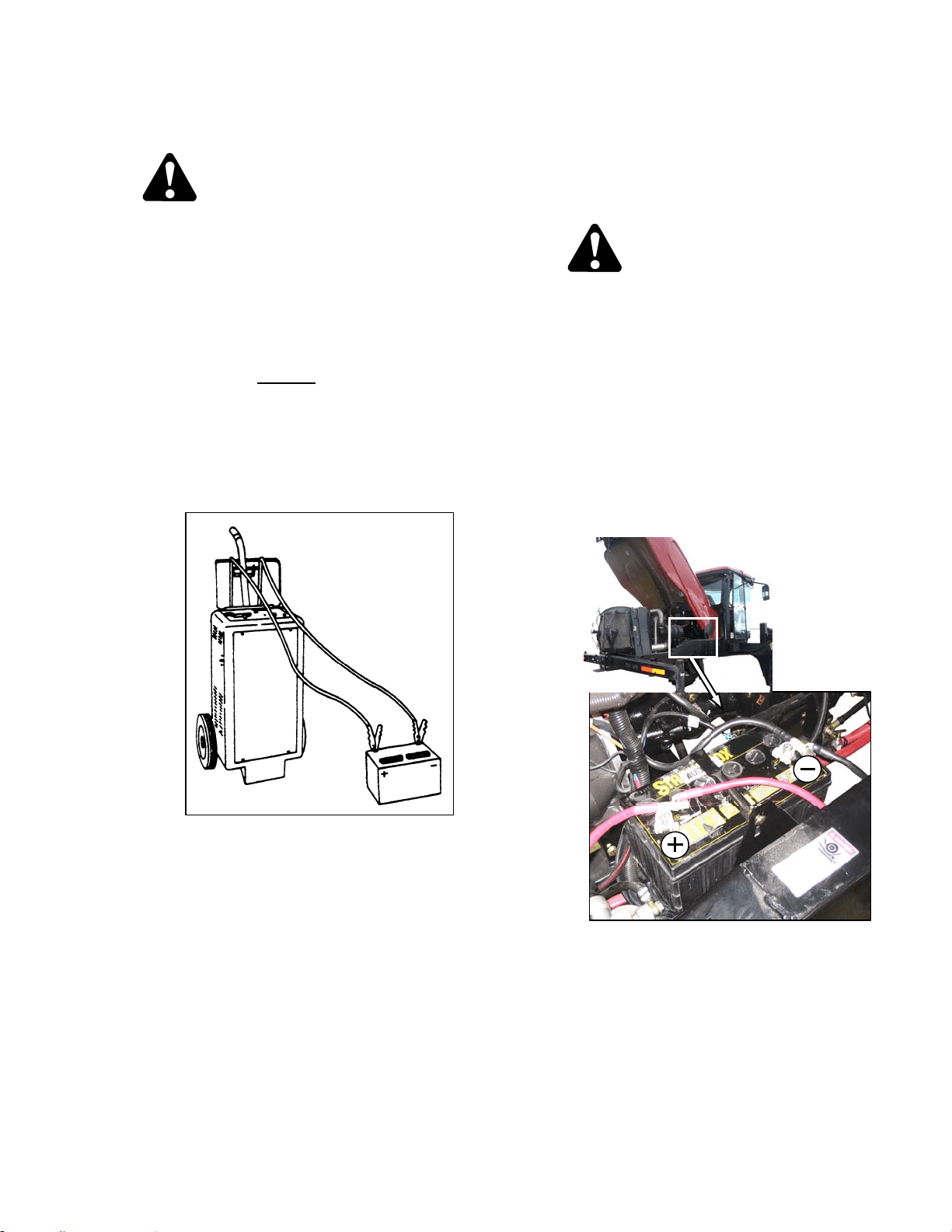
MAINTENANCE/SERVICE
169304 139 Rev. C
57.8.1.2 Charging
CAUTION
• Ventilate the area where batteries are
being charged.
• Do not charge a frozen battery. Warm to
60°F (16°C) before charging.
• Do not connect or disconnect live
circuits. To prevent sparks, turn off
charger and connect positive cable first.
If charging battery in windrower,
disconnect positive
battery cable before
connecting charger cable, then connect
ground cable last, away from battery.
• Stop or cut back charging rate if battery
feels hot, or is venting electrolyte.
Battery temperature must not exceed
125°F (52°C).
• Follow all instructions and precautions
furnished by the battery charger
manufacturer. Charge at recommended
rates and times.
57.8.1.3 Boosting
A twelve volt battery can be connected in
parallel (+ to +) with the windrower battery. Use
heavy duty battery cables.
CAUTION
• Gas given off by batteries is explosive.
Keep sparks and flames away from
batteries.
• Make last connection and first
disconnection at a point furthest away
from the batteries.
• Wear protective eye-wear when using a
booster battery.
• Be sure everyone is clear of machine
when starting engine. Start engine from
operator's station only.
a. Open engine compartment hood.
b. Remove red rubber cover (if attached) from
windrower battery positive terminal.
(continued next page)
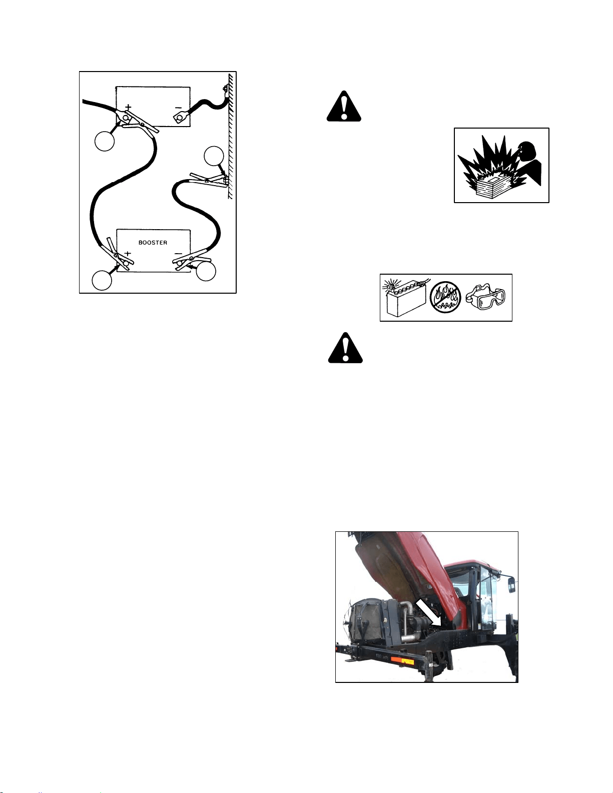
MAINTENANCE/SERVICE
169304 140 Rev. C
c. Attach one end of battery cable to positive
terminal (A) of booster battery and other end to
positive terminal (B) of windrower batteries.
d. Attach second cable to negative terminal (C) of
booster battery and then to a good ground (D)
on windrower frame.
e. Turn ignition switch in cab as with normal start
up.
f. After engine starts, disconnect cable from
windrower ground first, and then disconnect the
other cables.
g. Close hood.
57.8.1.4 Adding Electrolyte
WARNING
• Keep all smoking
materials, sparks and
flames away from
electrolyte container
and battery, as gas
given off by
electrolyte is
explosive.
• Battery electrolyte causes severe burns.
Avoid contact with skin, eyes or clothing.
Wear protective eyewear and heavy
gloves.
WARNING
If electrolyte is spilled or splashed on
clothing or on the body, neutralize it
immediately with a solution of baking soda
and water, then rinse with clean water.
Electrolyte splashed into the eyes is
extremely dangerous. Should this occur,
force the eye open and flood with cool, clean
water for five minutes. Call a doctor
immediately.
a. If battery is installed in windrower, shutdown the
engine and remove the key.
b. Open engine compartment hood to highest
position.
c. Add electrolyte in accordance with the battery
manufacturer’s instructions.
B
D
C
A
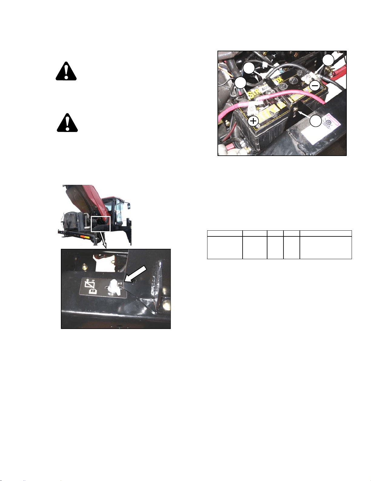
MAINTENANCE/SERVICE
169304 141 Rev. C
57.8.1.5 Replacing Battery
CAUTION
Do not attempt to service battery unless you
have the proper equipment and experience
to perform the job. Have it done by a
qualified dealer
DANGER
Stop engine and remove key from ignition
before leaving operator's seat for any
reason. A child or even a pet could engage
an idling machine.
a. Stop engine and remove key.
b. Open engine compartment hood.
c. Switch the battery disconnect switch to OFF.
d. Remove red plastic cover (if attached) from
positive cable clamp (A). Loosen the clamp and
remove cable from battery.
e. Loosen clamp (B) on negative terminal and
remove cable from battery.
f. Remove bolt (C) securing strap (D) to frame,
and remove strap.
g. Lift battery off holder.
RATING GROUP CCA VOLT MAX. DIMENSION
Heavy Duty,
Off-Road,
Vibration
Resistant
BCI 31A 950 12
13x6.81 x9.43 in.
(330x173x240 mm).
h. Position new battery on holder.
i. Install strap (D) with bolt (C).
IMPORTANT
BATTERY IS NEGATIVE GROUNDED.
Always connect starter cable to the
positive (+) terminal of battery and battery
ground cable to negative (-) terminal of
battery. Reversed polarity in battery or
alternator may result in permanent
damage to electrical system.
j. Attach negative (black) cable clamp (B) to
negative post on battery and tighten clamp.
k. Attach positive (red) cable clamp (A) to positive
post on battery and tighten. Reposition plastic
covers onto clamps.
l. Switch battery disconnect switch to ON.
m. Close hood.
A
B
C
D
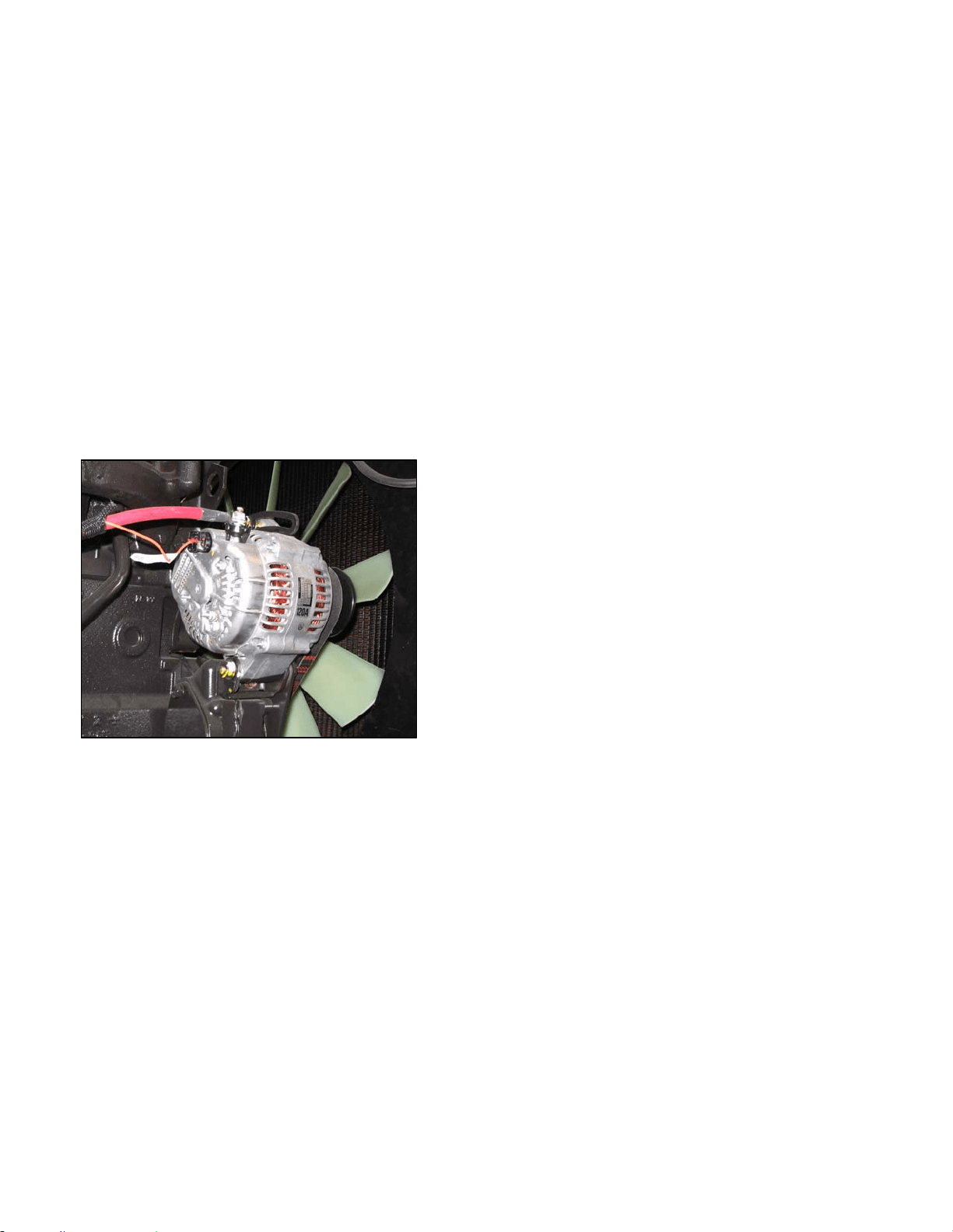
MAINTENANCE/SERVICE
169304 142 Rev. C
57.8.1.6 Preventing Electrical System Damage
a. Carefully observe polarity when attaching
booster battery.
b. Do not short across battery or alternator
terminals, or allow battery positive (+) cable or
alternator wire to become grounded.
c. Be sure alternator connections are correct
before cables are connected to battery. Refer to
illustration below.
d. When welding on any part of the machine,
disconnect battery cables and alternator wire.
e. Always disconnect battery ground cable when
working with the alternator or regulator.
f. Never attempt to polarize alternator or regulator.
g. If wires are disconnected from the alternator,
use the illustration below to ensure proper
reconnection.
h. Never ground the alternator field terminal or field
circuit.
i. Never connect or disconnect alternator or
regulator wires with battery connected or
alternator operating.
j. Always disconnect cables from the battery when
using a charger to charge battery in windrower.
k. Ensure all cables are securely connected before
operating engine.
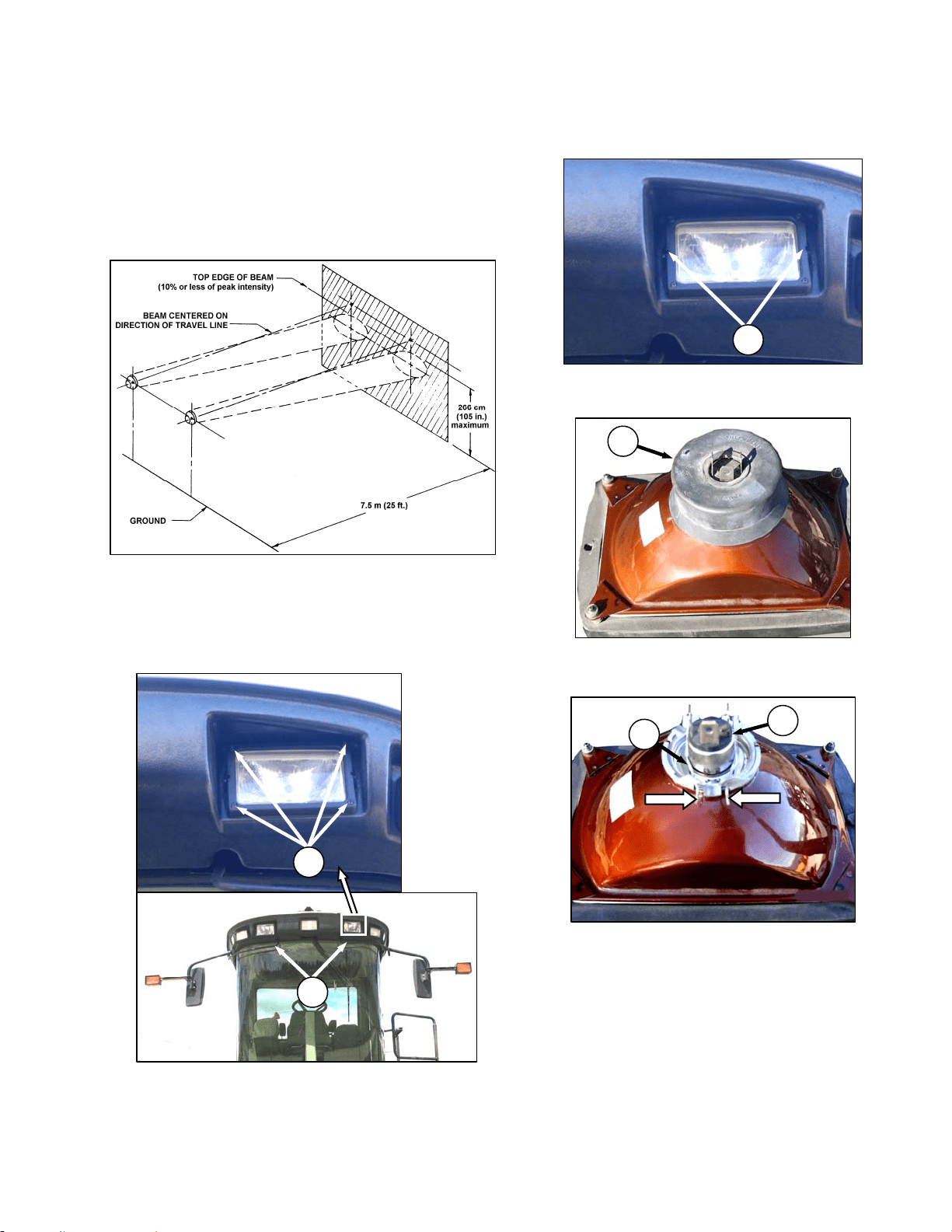
MAINTENANCE/SERVICE
169304 143 Rev. C
57.8.2 Headlights
57.8.2.1 Adjustment
Adjust for maximum illumination while ensuring
oncoming traffic cannot be blinded by the lights.
The recommended setting is:
• Light beams laterally centered on the
“direction of travel” line from the headlights
(i.e. not skewed left or right).
• Upper limit of the beam not higher than 105
inches (266 cm) above ground at a distance
of 25 ft. (7.5 m) from the headlight
a. Hold onto the hand-holds (A) on the cab front
corners and stand on the header anti-slip strips.
b. Adjust the lights with screws (B).
57.8.2.2 Bulb Replacement
a. Remove the two screws (C) and remove light
assembly.
b. Pull wiring harness connector off the headlight
assembly and remove rubber insulator boot (D).
c. Pinch the wire retainer (E) and lift away from
hooks.
d. Remove bulb (F) from body.
IMPORTANT
Do not touch the glass of the halogen bulb
as the oils or other chemicals from your
skin will cause the bulb to fail prematurely.
(continued next page)
C
B
A
E
F
D
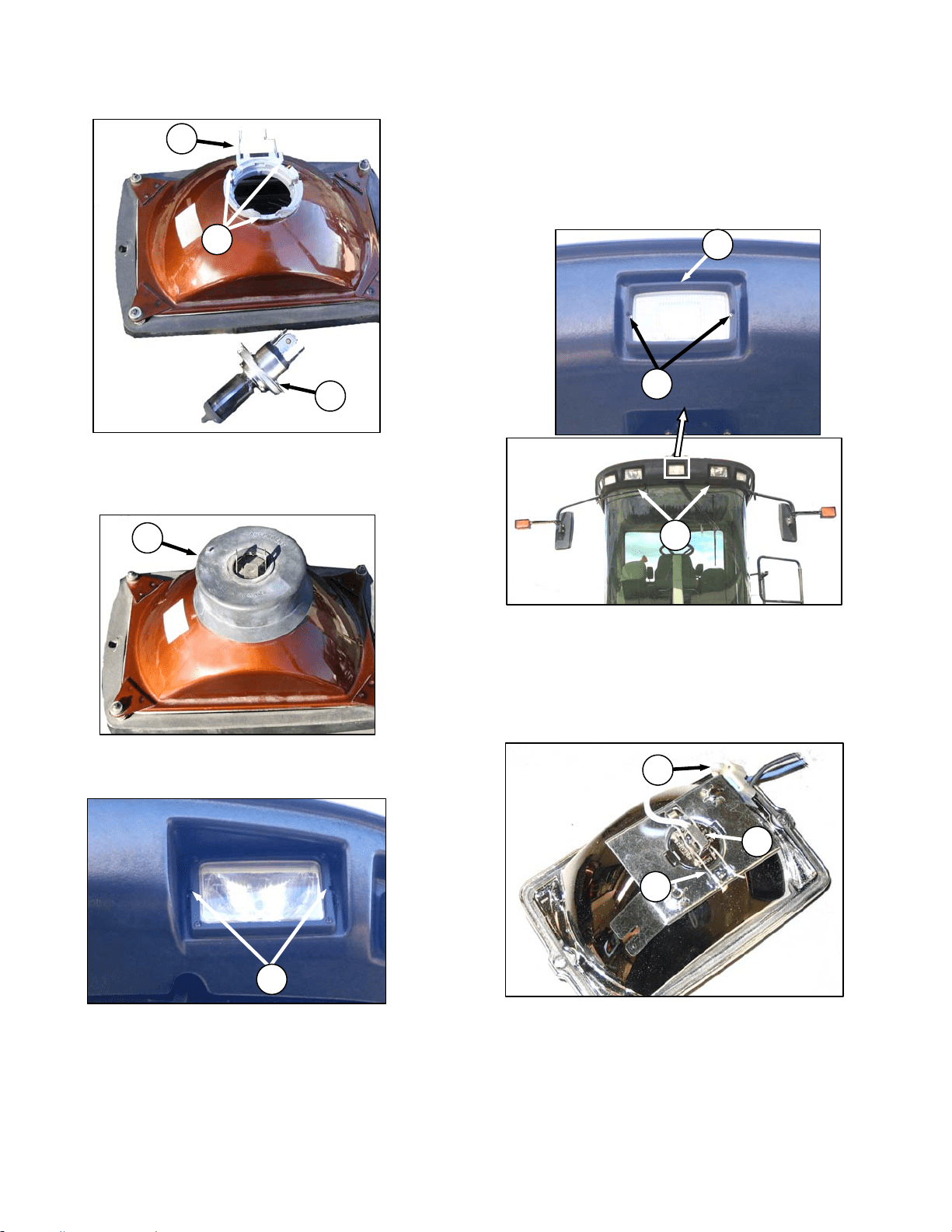
MAINTENANCE/SERVICE
169304 144 Rev. C
N
M
L
e. Align lugs on new bulb with slots (G) in body and
push into place.
f. Secure bulb with wire retainer (E)
g. Replace rubber insulator boot (D).
h. Push connector onto light bulb.
i. Position headlight into light receptacle, ensuring
top is up, and secure with screws (C).
NOTE
Aligning of light should not be necessary.
57.8.3 Flood Lights - Forward
The forward floodlights are not adjustable.
Replace bulbs as follows:
a. Shutdown engine and remove the key. Turn off
the lights.
b. Hold onto the hand-holds (H) on the cab front
corners and stand on the header anti-slip strips
when removing the forward field lights.
c. Remove the two screws (J) and remove light
bezel (K).
d. Remove light from receptacle.
e. Pinch the wire retainer (L) and lift away from
hooks.
f. Remove bulb (M) from body and pull wire from
connector (N).
(continued next page)
J
K
H
E
F
G
D
C
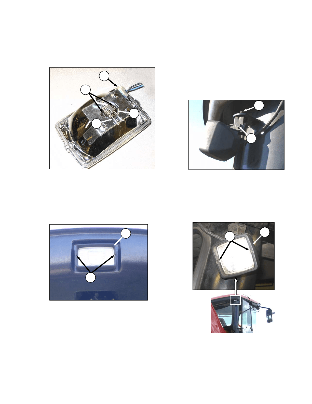
MAINTENANCE/SERVICE
169304 145 Rev. C
IMPORTANT
Do not touch the glass of the halogen bulb
as the oils or other chemicals from your
skin will cause the bulb to fail prematurely.
g. Match slots on new bulb (M) with lugs (O) in
optical unit and insert bulb into unit.
h. Secure bulb with wire retainer (L).
i. Push wire into connector (N).
IMPORTANT
For proper lighting pattern, be sure lights
are installed right side up.
j. Position light into light receptacle, ensuring top
is up, and secure with bezel (K) and screws (J).
57.8.4 Flood Lights - Rear
57.8.4.1 Adjustment
The rear floodlights are best adjusted with the
machine in the field or the equivalent to suit
operator preference.
a. Shutdown engine and remove the key. Turn on
lights.
b. Loosen bolts (A) and (B).
c. Position light to desired position.
d. Tighten bolts (A) and (B).
57.8.4.2 Bulb Replacement
a. Shutdown engine and remove the key. Turn off
the lights.
b. Remove the two screws (C) and remove light
bezel (D).
c. Remove light from receptacle.
(continued next page)
A
B
J
K
C
D
L
M
N
O
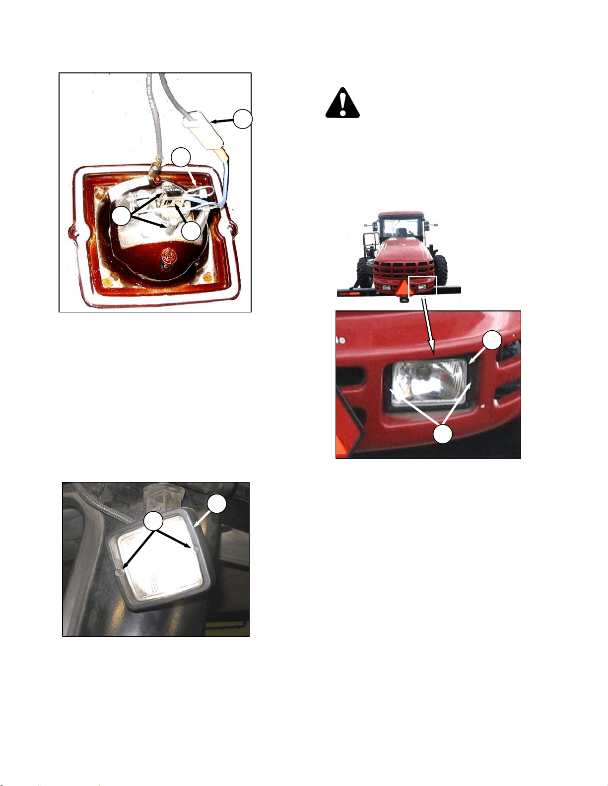
MAINTENANCE/SERVICE
169304 146 Rev. C
d. Pinch the wire retainer (E) and lift away from
hooks.
e. Remove bulb (F) from body and pull wire from
connector (G).
IMPORTANT
Do not touch the glass of the halogen bulb
as the oils or other chemicals from your
skin will cause the bulb to fail prematurely.
f. Match slots on new bulb (F) with lugs (H) in
optical unit and insert bulb into unit.
g. Secure bulb with wire retainer (E).
h. Push wire into connector (G).
i. Position light into light receptacle, ensuring top
is up, and secure with bezel (D) and screws (C).
57.8.5 Swath Lights
DANGER
Stop engine and remove key from ignition
before leaving operator's seat for any
reason. A child or even a pet could engage
an idling machine.
The swath lights are not adjustable. Replace
bulbs as follows:
a. Remove the two screws (A) and remove light
bezel (B).
b. Remove light from receptacle.
(continued next page)
C
D
G
H
E
F
A
B
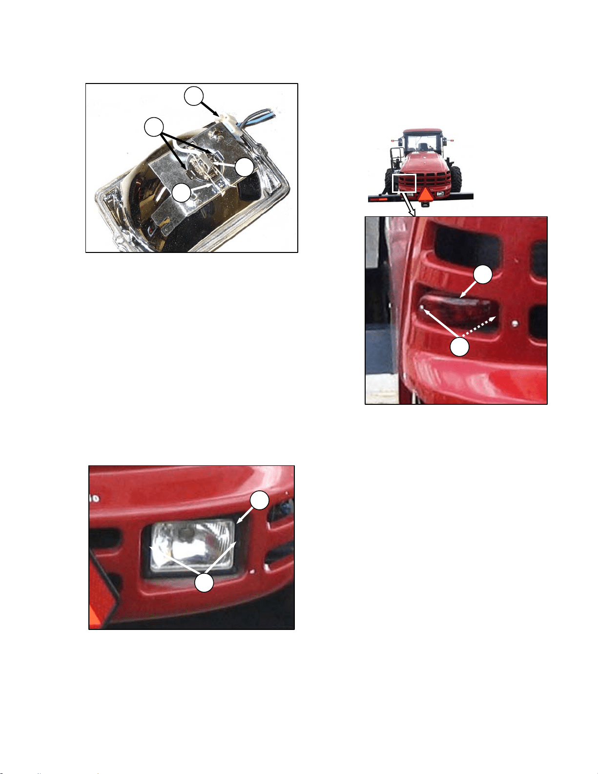
MAINTENANCE/SERVICE
169304 147 Rev. C
c. Pinch the wire retainer (J) and lift away from
hooks.
d. Remove bulb (K) from body and pull wire from
connector (L) .
IMPORTANT
Do not touch the glass of the halogen bulb
as the oils or other chemicals from your
skin will cause the bulb to fail prematurely.
e. Match slots on new bulb (K) with lugs (O) in
optical unit and insert bulb into unit.
f. Secure bulb with wire retainer (J).
g. Push wire into connector (L).
IMPORTANT
For proper lighting pattern, be sure lights
are installed right side up.
h. Position light into light receptacle, ensuring top
is up, and secure with bezel (B) and screws (A).
57.8.5.1 Red Tail Lights
a. Shutdown engine and remove the key. Turn off
the lights.
b. Remove two screws (C) from light (D) and
remove light.
c. Remove connector from light.
d. Connect wiring harness to new light and install
light with screws (C).
D
C
J
K
L
O
A
B
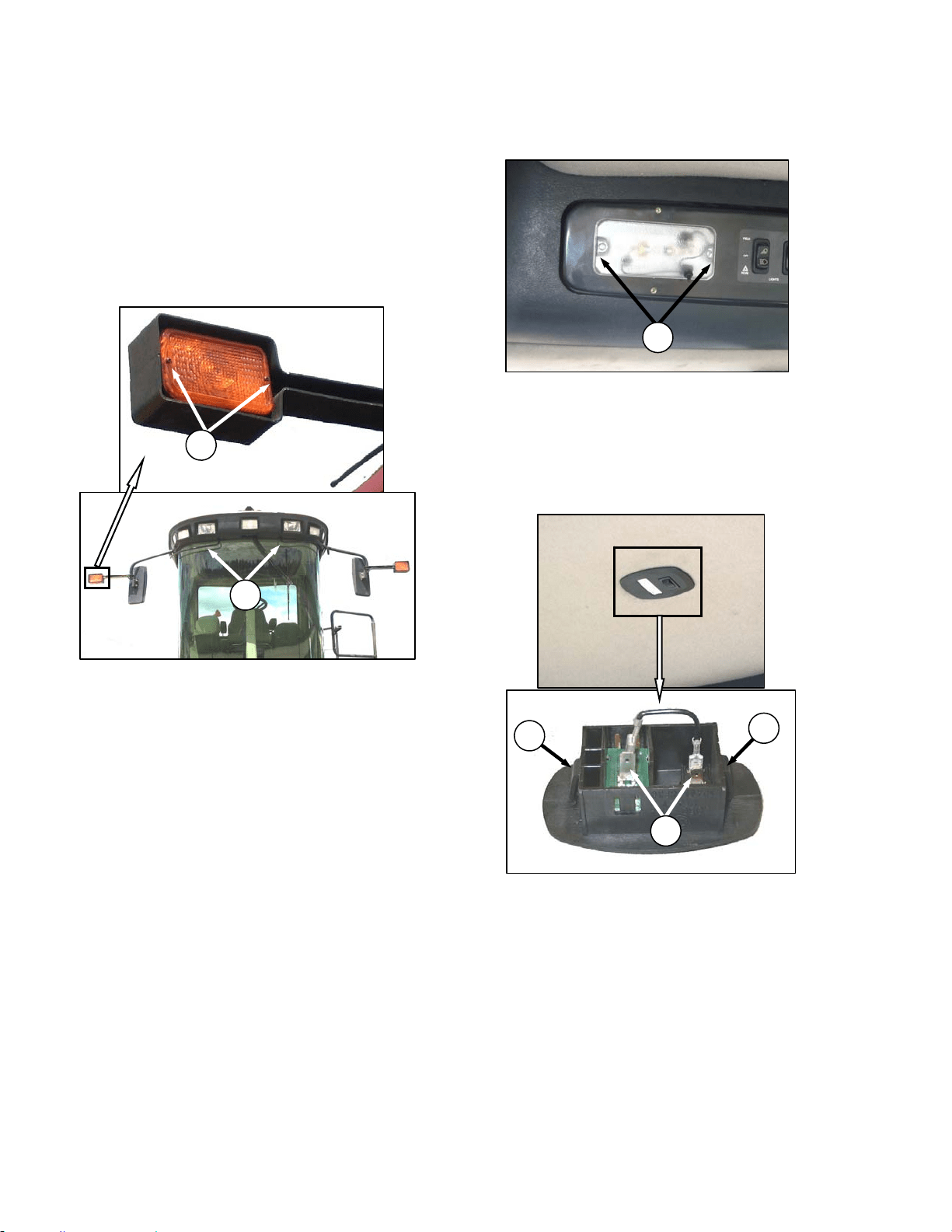
MAINTENANCE/SERVICE
169304 148 Rev. C
57.8.5.2 Amber Lights
a. Shutdown engine and remove the key. Turn off
the lights.
NOTE
Hold onto the hand-holds (A) on the cab
front corners and stand on the header
anti-slip strips or stand on the
maintenance platform when accessing the
amber lights.
b. Remove two screws (B) from lens and remove
lens.
c. Push and twist light bulb to remove from socket.
d. Install new bulb ensuring that bulb base is
properly engaged in socket. Use Bulb Trade
#1156.
e. Reinstall lens with screws (B).
57.8.5.3 Dome Light
a. Shutdown engine.
b. Remove two screws (C) from plastic lens and
remove lens.
c. Replace bulb.
d. Reinstall plastic lens with screws (C).
57.8.6 Ambient Light
a. Shutdown engine.
b. Push against tabs (D) with a screwdriver and
pull ambient light fixture out of cab roof.
c. Remove connectors (E).
d. Connect wires to new light fixture.
e. Push into place in cab roof until tabs hold fixture
in place.
57.8.7 Turn Signal Indicators
If the turn signal indicators on the CDM do not
function, contact your Windrower dealer.
C
A
B
D
E
D
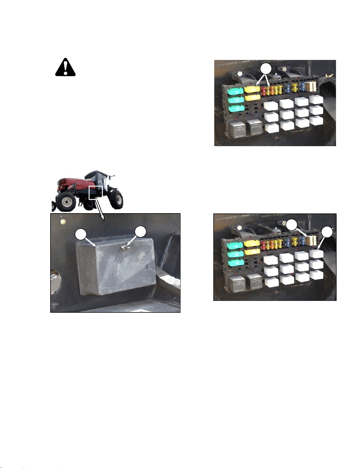
MAINTENANCE/SERVICE
169304 149 Rev. C
57.8.8 Circuit Breakers and Fuses
DANGER
Stop engine and remove key from ignition
before leaving operator's seat for any
reason. A child or even a pet could engage
an idling machine.
The circuit breakers and fuses are located inside
the fuse box that is mounted on the frame on the
right side of the windrower. The circuit breakers
automatically reset and the fuses are the plastic
blade type.
Access the breakers and fuses as follows:
a. Stop engine and remove key.
b. Remove wing nut (A) and remove fuse box
cover (B).
c. Refer to decal on inside of cover for
identification of fuses and circuit breakers. See
illustration next page. SEE BG
57.8.8.1 Checking/Replacing Fuses
a. To check fuse, pull fuse (C) out of receptacle
and visually examine.
b. To replace fuse, insert new fuse into receptacle.
IMPORTANT
Replacement fuses should match rating
on decal shown on following page.
57.8.8.2 Replacing Circuit Breakers
a. To replace circuit breaker (D), pull breaker out of
receptacle, and install new circuit breaker.
b. To replace relay (E), pull relay out of receptacle,
and install new relay.
c. Reinstall cover and secure with wing nut.
C
A
B
D
E
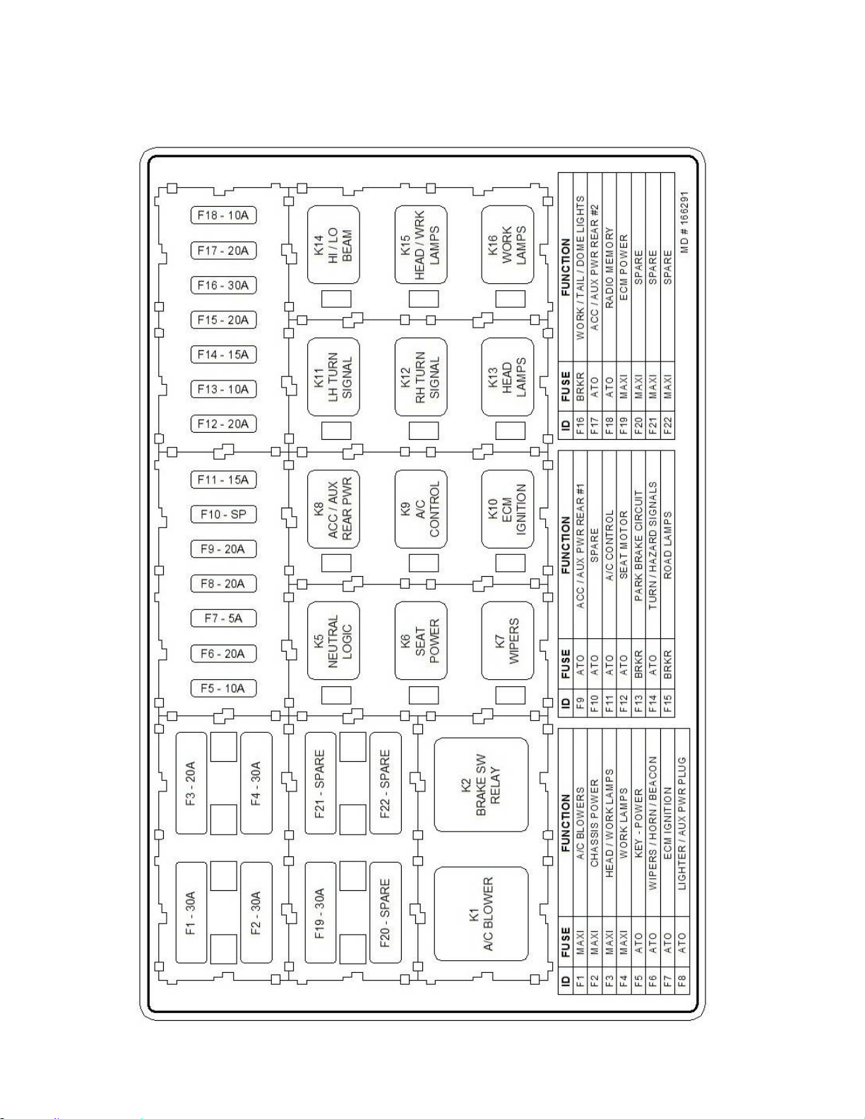
MAINTENANCE/SERVICE
169304 150 Rev. C
57.8.8.3 Fuse Box Decal
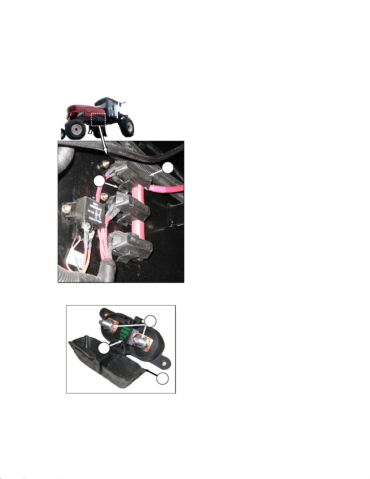
MAINTENANCE/SERVICE
169304 151 Rev. C
57.8.8.4 Main Fuses - 125 Amp
The 125 amp main fuse holders are located
inside the frame beside the battery and are
accessed from underneath the windrower.
a. Stop engine and remove key.
b. To check condition of fuse, pull tab (A) and open
cover (B).
c. Visually examine fuse (C) for indications of
melting.
d. To remove fuse (C), remove two nuts (D) and
pull fuse free from holder. Existing wiring may
need to be pulled off the stud first.
e. Install new fuse on studs and any existing wiring
that was removed.
f. Secure with nuts (D).
g. Close cover (B) and secure with tab (A).
A
B
B
D
C
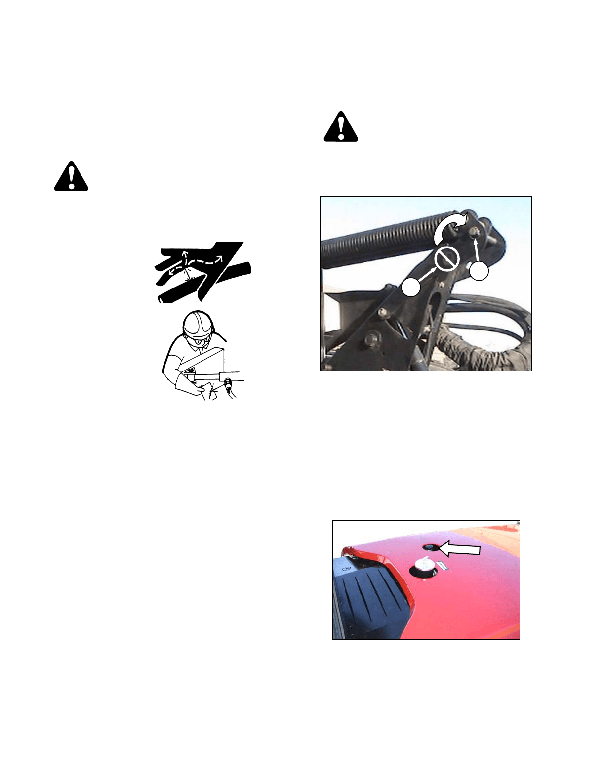
MAINTENANCE/SERVICE
169304 152 Rev. C
57.9 HYDRAULIC SYSTEM
The M100 Windrower hydraulic system provides
oil for the windrower drive system, and header
lift and drive systems.
Hydraulic schematics are placed at the back of
this manual.
WARNING
Avoid high pressure fluids. Escaping fluid
can penetrate the skin causing serious
injury. Relieve pressure before
disconnecting hydraulic lines. Tighten all
connections
before applying
pressure. Keep
hands and body
away from pin-
holes and nozzles
which eject fluids
under high
pressure. Use a
piece of
cardboard or
paper to search
for leaks. If ANY
fluid is injected
into the skin, it
must be surgically removed within a few
hours by a doctor familiar with this type of
injury or gangrene may result.
IMPORTANT
Dirt, dust, water and foreign material are
the major causes of trouble developing in
the hydraulic system. If the hydraulic
system should be disconnected for
service, protect the ends of hoses, tubing
and ports of components from
contamination with clean, lint-free towels
or clean plastic bags. Before installing
any replacement hose, flush the inside of
it with unused diesel fuel or unused
commercial petroleum cleaning solvent for
ten seconds minimum. Do not use water,
water soluble cleaners or compressed air.
IMPORTANT
The components in this system are built to
very close tolerances and have been
adjusted at the factory. Do not attempt to
service these components except to
maintain proper oil level, change oil and
filters and to adjust relief pressures as
described in this manual. See your
Windrower Dealer for all other service.
57.9.1 Oil Level
Check hydraulic oil level when oil is cold for
most accurate reading:
DANGER
Stop engine and remove key from ignition
before leaving operator's seat for any
reason. A child or even a pet could engage
an idling machine.
IMPORTANT
To prevent damage to the lift system when
lowering header lift linkages without a
header or weight box attached to
windrower, ensure that float engagement
pin is installed in storage location (A), and
not installed at hole location (B).
a. Park windrower on level ground and lower
header and reel so that lift cylinders are fully
retracted.
b. Stop engine and remove key.
c. Stand on platform to access the filler pipe.
d. Turn filler cap counterclockwise to loosen bung,
and remove dipstick.
(continued next page)
B
A

MAINTENANCE/SERVICE
169304 153 Rev. C
e. Maintain level between LOW and FULL marks.
If necessary, add SAE 15W40 Compliant with
SAE Specs for API Class SJ and CH-4 Engine
Oil.
NOTE
LOW to FULL capacity is approximately 1
U.S. gallon (4 liters).
f. Reinstall filler cap and turn clockwise to tighten
bung.
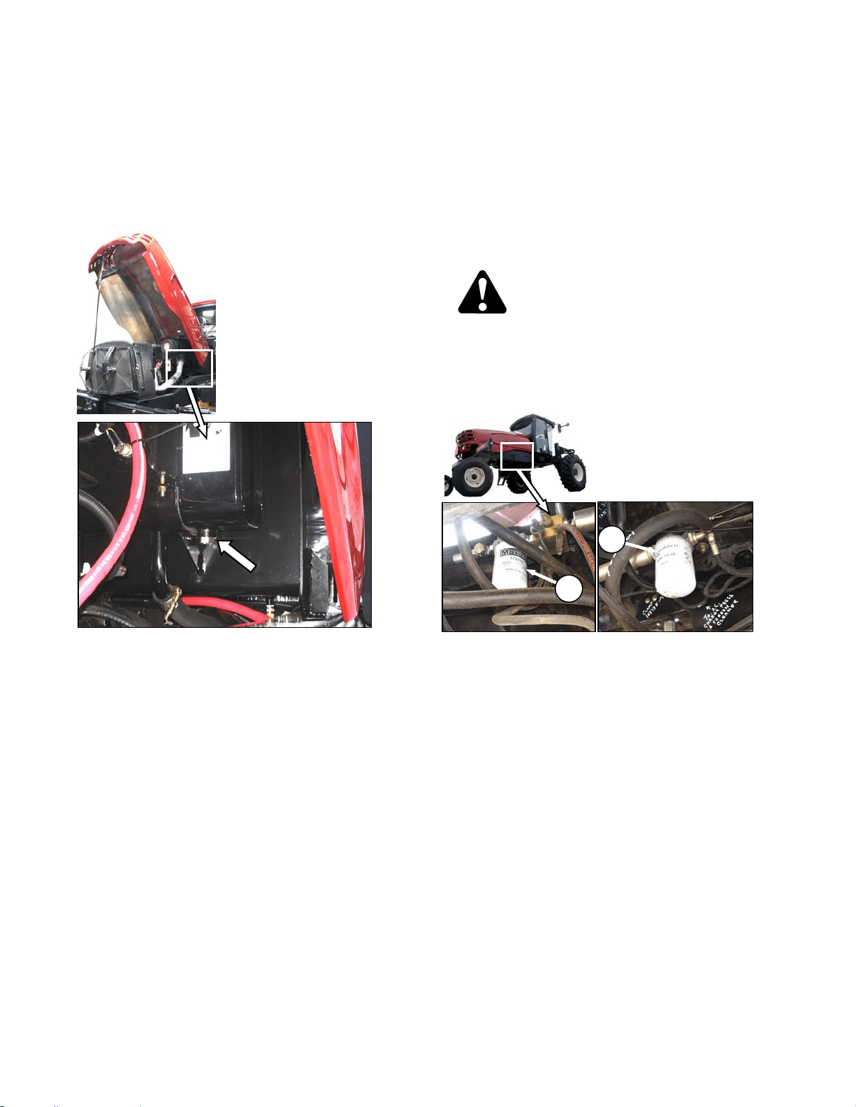
MAINTENANCE/SERVICE
169304 154 Rev. C
57.9.2 Changing Hydraulic Oil
NOTE
Change hydraulic oil every 2000 hours.
a. Stop engine and remove key.
b. Open engine compartment hood to highest
position.
c. Place a suitable container (at least 20 gal. US
(75 liters)) under drain to collect oil.
d. Remove drain plug from bottom of hydraulic oil
reservoir and allow oil to drain.
e. Clean off any metal debris that my have
accumulated on magnetic drain plug. Replace
and tighten drain plug.
f. Add oil to the tank to the required level through
the filler pipe. Refer to previous section.
57.9.3 Hydraulic Oil Cooler
The hydraulic oil cooler is located inside the
cooling box behind the radiator. It should be
cleaned daily with compressed air. Refer to
Section 7.9.2 Cooling Box Maintenance.
57.9.4 Hydraulic Oil Filters
NOTE
Change hydraulic oil filters after the first
50 hours of operation and every 500 hours
thereafter. Filter (A) part #112420 and
filter (B) part #151975 can be obtained
from your dealer.
The hydraulic system contains two filters.
Change hydraulic oil filters as follows:
DANGER
Stop engine and remove key from ignition
before leaving operator's seat for any
reason. A child or even a pet could engage
an idling machine.
a. Stop engine and remove key.
b. Clean around heads of the filters (A) and (B).
c. Unscrew the filters with a filter wrench.
d. Clean the gasket surface of the filter heads.
e. Fill new filters with clean oil and apply a thin film
of clean oil to the filter gaskets.
f. Screw the new filters onto the mount until the
gasket contacts the filter head.
g. Tighten filters an additional ½ turn by hand.
IMPORTANT
Do not use a filter wrench to install oil
filter. Over-tightening can damage gasket
and filter.
A
B
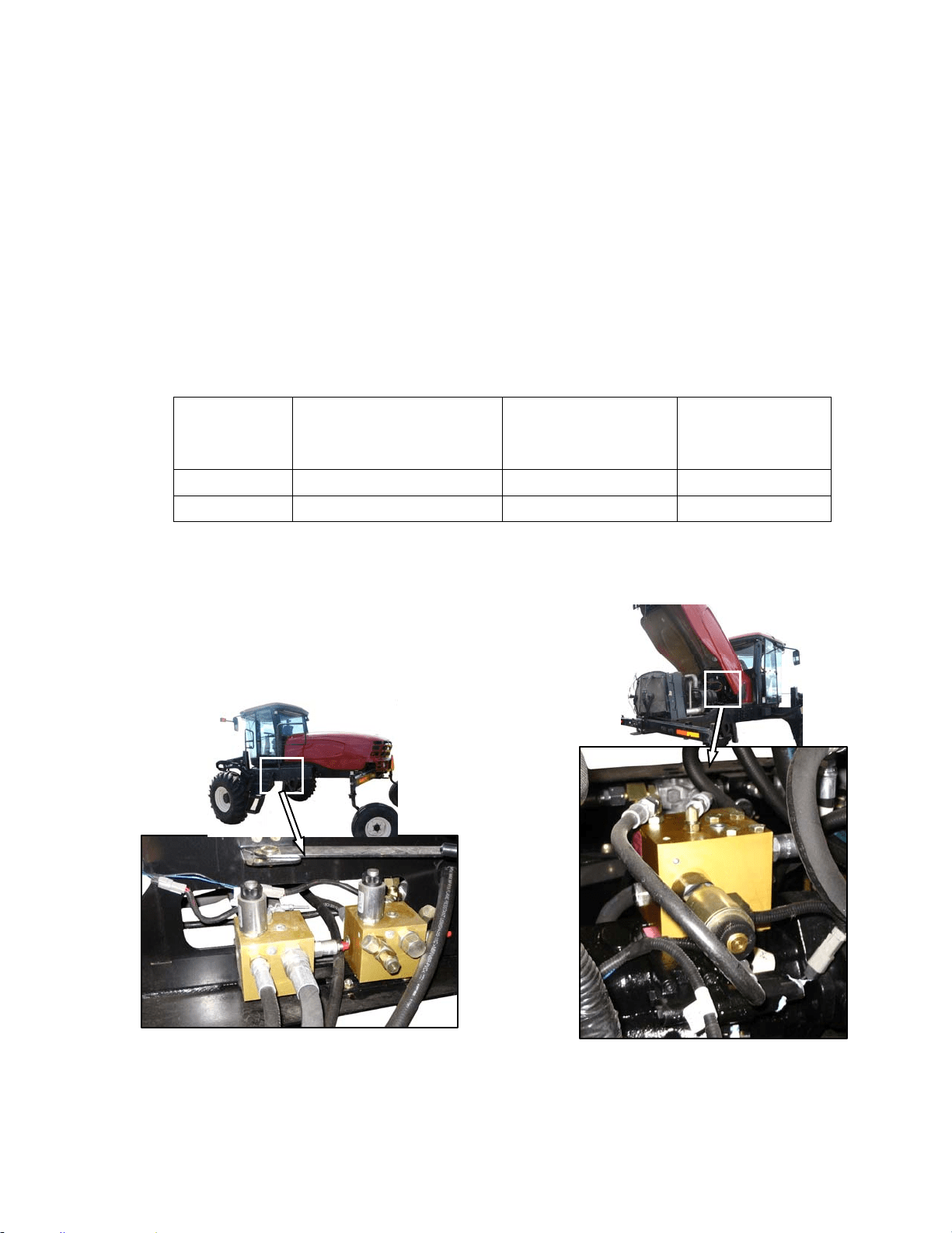
MAINTENANCE/SERVICE
169304 155 Rev. C
57.9.5 Header and Reel Hydraulics
57.9.5.1 Pressure Compensator Valve
The pressure compensator valve is pre-set to be
sufficient for all header sizes and options. See
table below.
When the knife drive pressure approaches the
compensator valve setting, a warning tone
sounds on the CDM, indicating a potential
overload on the header drive. If operation
continues, and the pressure reaches the setting,
the compensator valve is activated. The header
drive will begin to slow down. To avoid
overheating the drive pumps, reduce the ground
speed to maintain the correct system load and
knife drive operation.
NOTE
The warning tone is normal when the
operating pressure is very close to the
compensator valve pressure setting.
If lift and reel or draper drive capacity problems
develop, the pressure compensator valve may
require adjusting. Contact your Windrower
Dealer or refer to the Technical Service Manual
for your Windrower.
HEADER MODEL APPLICATION/SYSTEM SUGGESTED OVERLOAD
WARNING SETTING
psi (kPa)
WINDROWER
PRESSURE COMP
SETTING
psi (kPa)
D60 & A40D Reel/Draper Pressure 3000 (20684) 3200 (22063)
D60 & A40D Knife/Conditioner Pressure 4000 (27579) 4200 (28958)
57.9.5.2 Reel/Conveyor Flow Control Block
Two hydraulic valve blocks control the reel and
conveyor functions, and are controlled by the
Windrower Control Module (WCM) according to
the inputs from the operator. The valve blocks
are located behind the maintenance platform.
The valve blocks do not require any scheduled
maintenance other than to check for leaking
fittings or loose electrical connections. If service
is required, contact your Windrower Dealer or
refer to the Technical Service Manual for your
Windrower.
57.9.5.3 Knife Drive Valve Block
The ON/OFF valve on the valve block regulates
the knife speed, and is mounted on top of the

MAINTENANCE/SERVICE
169304 156 Rev. C
knife drive pump. The flow to the knife drive is
mechanically set on the pump itself.
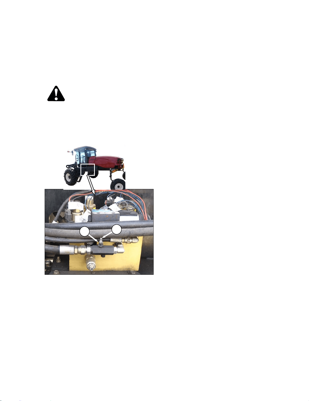
MAINTENANCE/SERVICE
169304 157 Rev. C
57.9.5.4 Header Drop Rate
The header should lower gradually when the
lower header switch is pressed. From full height
to ground should take approximately 3.5
seconds.
Adjust as follows:
DANGER
Stop engine and remove key from ignition
before leaving operator's seat for any
reason. A child or even a pet could engage
an idling machine.
a. Lower header to ground, stop engine, and
remove key.
b. Move maintenance platform rearward.
c. Loosen jam-nut (A) on needle valve and turn
screw (B) clockwise to decrease the drop rate
and counter-clockwise to increase the drop rate.
d. Tighten jam-nut (A).
e. Close platform and engine compartment hood.
f. Check drop rate and re-adjust as required.
B
A
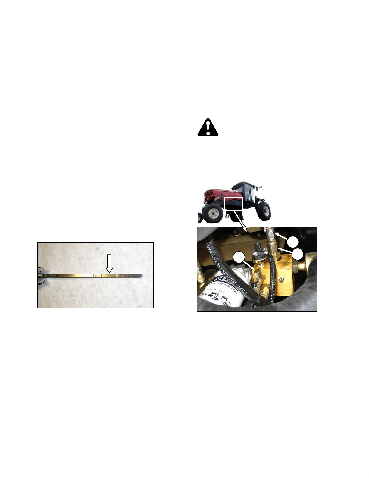
MAINTENANCE/SERVICE
169304 158 Rev. C
57.9.6 Traction Drive Hydraulics
57.9.6.1 Transmission Oil Pressure
The windrower transmission consists of two
variable displacement axial piston hydraulic
pumps, one for each drive wheel. The pumps
are direct driven through a coupling to the
engine. Each pump requires charge flow to
make up for internal leakage, maintain positive
pressure in the main circuit, provide flow for
cooling and replace any leakage losses from
external valving or auxiliary systems. The
charge pressure is monitored and if it drops
below 150 psi (1035 kPa), the CDM sounds a
tone and displays a flashing warning. Refer to
Section 5.17.4 Warnings and Alarms.
IMPORTANT
Rated charge pressure must be
maintained under all conditions of
operation to prevent damage to the
transmission.
If the TRANS OIL PRESSURE warning is
displayed, shutdown the engine and proceed as
follows:
a. Check the hydraulic fluid level in the tank. Refer
to Section 7.11.1 Oil Level.
b. Check the hoses and lines for leakage.
c. Check the charge pressure relief valve. Refer to
following section.
d. If charge pressure still cannot be maintained, do
not operate the windrower. Contact your
windrower dealer.
57.9.6.2 Charge Pump Pressure
Incorrect charge pressure settings may result in
the inability to build required system pressure
and/or inadequate loop flushing flows. Correct
charge pressure must be maintained under all
conditions to maintain pump control
performance and to operate the brake release
Check and adjust charge pump pressure as
follows:
DANGER
Stop engine and remove key from ignition
before leaving operator's seat for any
reason. A child or even a pet could engage
an idling machine.
a. Open engine compartment hood fully.
b. Remove cap (A) at fitting.
c. Attach a 0 - 600 psi (4000 kPa) pressure gauge
to a hose that is long enough to allow pressure
gauge to be read from the operator's seat.
Attach hose to the fitting.
d. Start engine and leave at idle. Pressure should
be 200 to 250 psi (1379 to 1724 kPa) with the
hydraulic oil at 100°F. (40°C) minimum.
e. If pressure is not within this range, adjust relief
pressure as follows:
1. Shut off engine and remove key.
2. Remove cap (C) from relief valve (B) for
access to adjustment screw.
(continued next page)
A
C
B
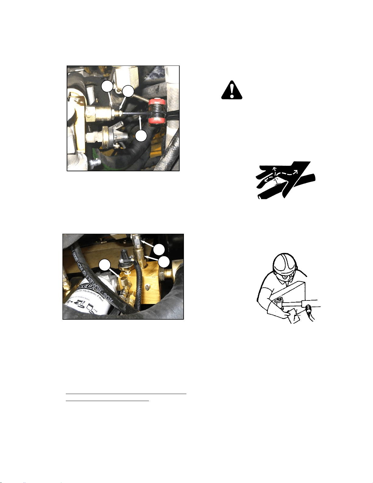
MAINTENANCE/SERVICE
169304 159 Rev. C
3. Hold screw (D) with Allen wrench (E) and
loosen jam-nut (F).
4. Adjust screw as required.
5. Repeat checking and adjustment until relief
pressure is correct, then tighten jam-nut (E)
while holding screw (D). Replace cap (C).
f. If relief pressure does not increase after
adjusting two or three times, check relief valve
as follows:
1. Remove relief valve (B) from manifold.
2. Check that no contaminant is preventing the
spring-loaded poppet from properly seating
against the valve body.
3. Clean as required with a solvent type
cleaner and compressed air, and reinstall
valve.
4. Check all seals for integrity.
5. Reset adjustment screw to original position
before checking relief pressure.
g. Remove pressure gauge hose and reinstall cap
(A) to fitting.
57.9.7 Hoses and Lines
Check hydraulic hoses and lines daily for signs
of leaks.
WARNING
Avoid high-pressure fluids. Escaping fluid
can penetrate the skin causing serious
injury. Relieve pressure before
disconnecting hydraulic lines. Tighten all
connections before applying pressure. Keep
hands and body away from pin- holes and
nozzles which eject fluids under high
pressure.
If ANY fluid is injected into the skin, it must
be surgically removed within a few hours by
a doctor familiar with this type of injury or
gangrene may result. Use a piece of
cardboard or paper to search for leaks.
IMPORTANT
Keep hydraulic coupler tips and
connectors clean. Dust, dirt, water and
foreign material are the major causes of
hydraulic system damage. DO NOT
attempt to service hydraulic system in the
field. Precision fits require WHITE ROOM
CARE during overhaul.
E
F
D
A
C
B
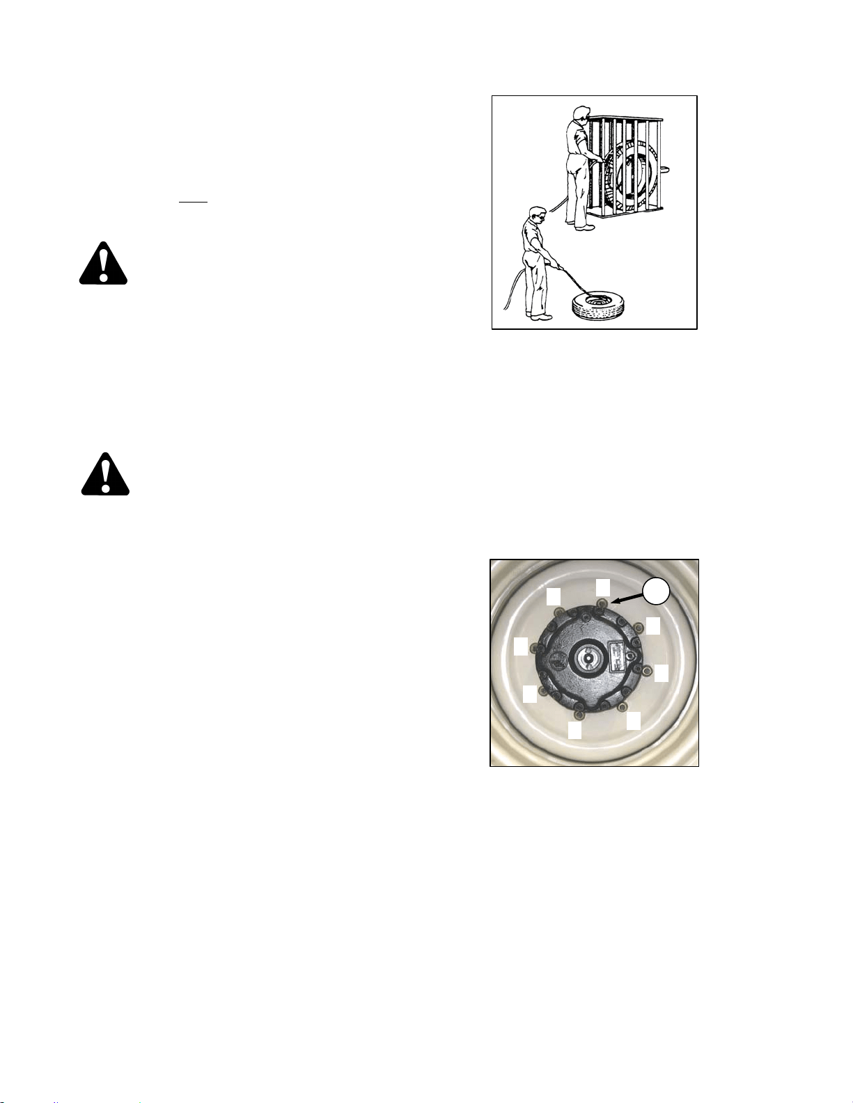
MAINTENANCE/SERVICE
169304 160 Rev. C
57.10 WHEELS AND TIRES
57.10.1 Drive Wheels
57.10.1.1 Tire Inflation
a. Visually check daily
that tires have not lost
pressure. Under-inflation of drive tires can
cause side wall cracks.
DANGER
To avoid severe personal injury or death
caused by machine runaway, shut off engine
and remove key before performing any of the
following checks and/or adjustments.
b. Measure tire pressure annually with a gauge.
Maintain the pressure as follows:
Bar – 32 psi (221 kPa)
Turf – 20 psi (138 kPa)
DANGER
• Never install a tube in a cracked wheel
rim.
• Never weld a wheel rim.
• Make sure all the air is removed from a
tire before removing the tire from the rim.
• Never use force on an inflated or partially
inflated tire. Make sure the tire is
correctly seated before inflating to
operating pressure.
• Do not remove, install or make repairs to
a tire on a rim unless you have the
proper equipment and experience to
perform the job. Take the tire and rim to a
qualified tire repair shop.
• If the tire is not in correct position on the
rim, or if too full of air, the tire bead can
loosen on one side, causing air to leak at
high speed and with great force. An air
leak of this nature can thrust the tire in
any direction, endangering anyone in the
area.
• Do not exceed manufacturer’s
recommended inflation pressure.
• Use a safety cage if available.
• Do not stand over tire. Use a clip-on
chuck and extension hose.
57.10.1.2 Wheel Nut Torque
At first use, or when a wheel is removed, check
drive wheel nut torque every 15 minutes on the
road or 1 hour in the field until the specified
torque is maintained. Continue with a checking
schedule of 10 and 50 hours (field or road
operation), and then every 200 hour intervals
thereafter.
a. Tighten nuts (C) to 220 ft·lbf (300 N·m) using the
tightening sequence as shown.
NOTE
To avoid damage to wheel disks, do not
over-tighten wheel nuts.
b. Repeat sequence three times.
1
5
3
7
8
2
4
6
C
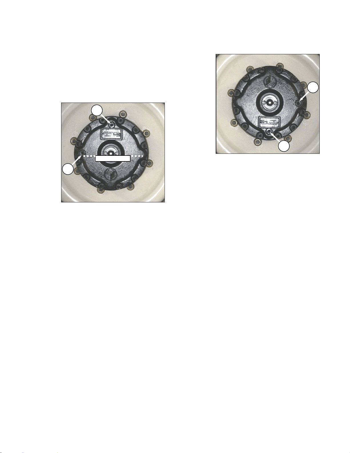
MAINTENANCE/SERVICE
169304 161 Rev. C
57.10.1.3 Lubricant
The drive wheel gearbox lubricant should be
changed after the first 50 hours. Check the level
every 200 hours or annually and change every
1000 hours. The windrower should be on level
ground when checking lubricant level.
a. Check the lubricant as follows:
1. Rotate wheel so that plug (A) is located at
the top as shown.
2. Remove plug (B). The lubricant should be
visible through the hole or slightly running
out.
NOTE
Type of lubricant used after first lubricant
change is different from factory supplied
lubricant.
b. If lubricant needs to be added, remove plug (A),
and add lubricant until lubricant runs out at (B).
Prior to first change, use SAE 85W-140, API
Service, Class GL-5, Extreme Pressure Gear
Lubricant. After first change, use SAE 75W-90,
API Service, Class GL-5, Fully Synthetic
Transmission Lubricant (SAE J2360 preferred).
c. Replace plugs and tighten.
d. Change the lubricant as follows:
1. Rotate the wheel so that plug (A) is located
at the bottom.
2. Place a large enough container (about 2
quarts U.S. (2 liters) under the drain plug
(A).
3. Remove plugs (A) and (B) and drain
lubricant. Ideally, the lubricant should be at
operating temperature for good draining.
4. When lubricant has drained, rotate wheel so
that plug (A) is at the top.
NOTE
Type of lubricant used after first lubricant
change is different from factory supplied
lubricant.
5. Add lubricant through (A) until lubricant runs
out of hole at (B). Use SAE 75W-90, API
Service, Class GL-5, Fully Synthetic
Transmission Lubricant (SAE J2360
preferred). Drive wheel gearbox capacity is
1.5 qts. U.S. (1.4 liters).
6. Replace both plugs and tighten.
A
B
OIL LEVEL
A
B
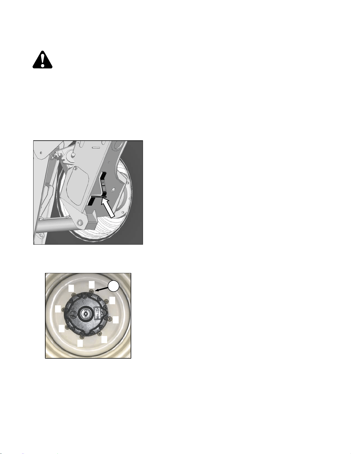
MAINTENANCE/SERVICE
169304 162 Rev. C
57.10.1.4 Drive Wheel Removal/Installation
DANGER
To avoid severe personal injury or death
caused by machine runaway, shut off engine
and remove key before performing any of the
following checks and/or adjustments.
a. Remove header.
b. Park windrower on level ground and block all
wheels.
c. Place GSL in N-DETENT, shutdown engine and
remove key.
d. Position a 5000 lb (2270 kg) jack under leg jack
point and raise windrower wheel slightly off
ground.
e. Undo wheel nuts (C) and remove wheel.
f. To install new tire, ensure that air valves are on
outside and tire tread point forward. For "Turf”
tires (diamond tread), be sure arrow on sidewall
points in forward rotation.
g. Position wheel on hub and install wheel nuts (C).
h. Tighten nuts (C) to 220 ft·lbf (300 N·m) using the
tightening sequence as shown.
NOTE
To avoid damage to wheel disks, do not
over-tighten wheel nuts.
i. Repeat sequence three times.
j. Lower windrower and remove jack.
1
5
3
7
8
2
4
6
C
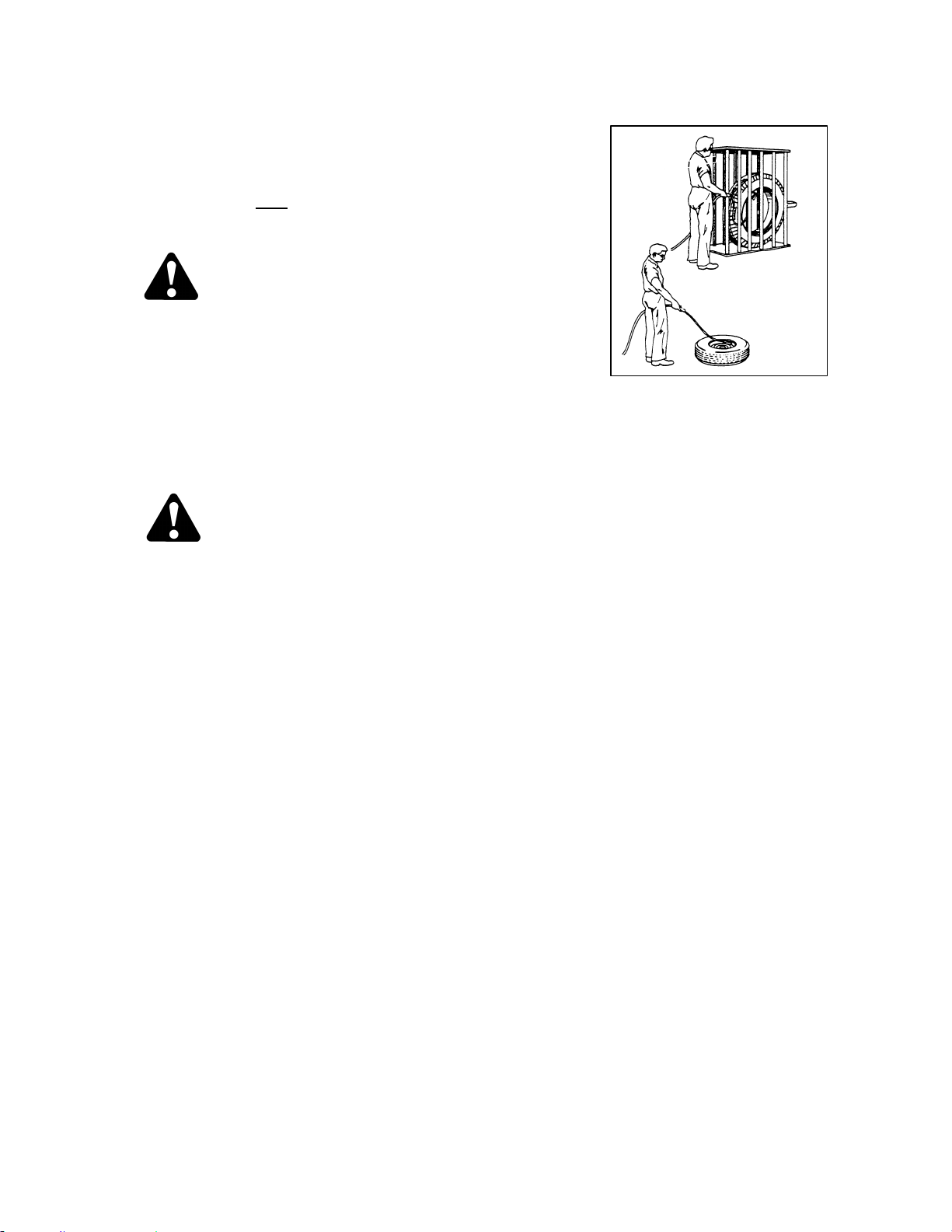
MAINTENANCE/SERVICE
169304 163 Rev. C
57.10.2 Caster Wheels
57.10.2.1 Tire Inflation
a. Visually check daily
that tires have not lost
pressure. Under-inflation of drive tires can
cause side wall cracks.
DANGER
To avoid severe personal injury or death
caused by machine runaway, shut off engine
and remove key before performing any of the
following checks and/or adjustments.
b. Measure tire pressure annually with a gauge.
Maintain the pressure at 10 psi (69 kPa).
NOTE
If caster wheels shimmy a possible cause
is over-inflation:
DANGER
• Never install a tube in a cracked wheel
rim.
• Never weld a wheel rim.
• Make sure all the air is removed from a
tire before removing the tire from the rim.
• Never use force on an inflated or partially
inflated tire. Make sure the tire is
correctly seated before inflating to
operating pressure.
• Do not remove, install or make repairs to
a tire on a rim unless you have the
proper equipment and experience to
perform the job. Take the tire and rim to a
qualified tire repair shop.
• If the tire is not in correct position on the
rim, or if too full of air, the tire bead can
loosen on one side, causing air to leak at
high speed and with great force. An air
leak of this nature can thrust the tire in
any direction, endangering anyone in the
area.
• Use a safety cage if available.
• Do not stand over tire. Use a clip-on
chuck and extension hose.

MAINTENANCE/SERVICE
169304 164 Rev. C
57.10.2.2 Ballast Requirements
Fluid ballasting of rear caster tires is
recommended to provide adequate machine
stability when using large headers on the
windrower. Also, the stability of machine varies
with different attachments, windrower options,
terrain and operator’s driving technique.
Ballast capability per tire is at a maximum fill of
75% or when fluid is level with valve stem when
the stem is positioned at 12 o’clock. Fluid can
be added to any level up to maximum fill and
always add an equal amount of fluid on both
sides.
TIRE SIZE
FLUID PER
TIRE
AT 75% FILL
U.S. Gal. (Liters)
TOTAL WEIGHT
OF BOTH
TIRES
lb (kg) *
7.5X16
(A)
10 (38) 200 (91)
10X16
(B)
18 (69) 380 (170)
16.5X16.1
(C)
41 (158) 830 (377)
* Weights are given for typical calcium chloride
and water mixtures. Weight is reduced by 20%
if only water is used (for areas that do not
require anti-freeze protection).
HEADER DESCRIPTION
RECOMMENDED BALLAST
RECOMMENDED
TIRE SIZE
LEVEL GROUND HILLS
TYPE SIZE
PER
TIRE BOTH TIRES PER TIRE BOTH TIRES
U.S. Gal.
(Liters)
lb (kg) *
U.S. Gal.
(Liters)
lb (kg) *
A & D Series All
Options
25’ and Down 0 0 0 0 A,B,C
D Series
30’ Single Or
Split Reel W/O
Conditioner.
35’ Single Reel
0 0 10 (38) 200 (91) A,B,C
30’ Split Reel.
Steel Fingers &
Conditioner.
35’ Split Reel (5
Or 6 Bat)
18 (69) 380 (170) 30 (115) 630 (288)
Level Ground –
B, C
Hills - C
* If only water is used, increase volume of water by 20% (up to maximum allowable fill per tire) to compensate.
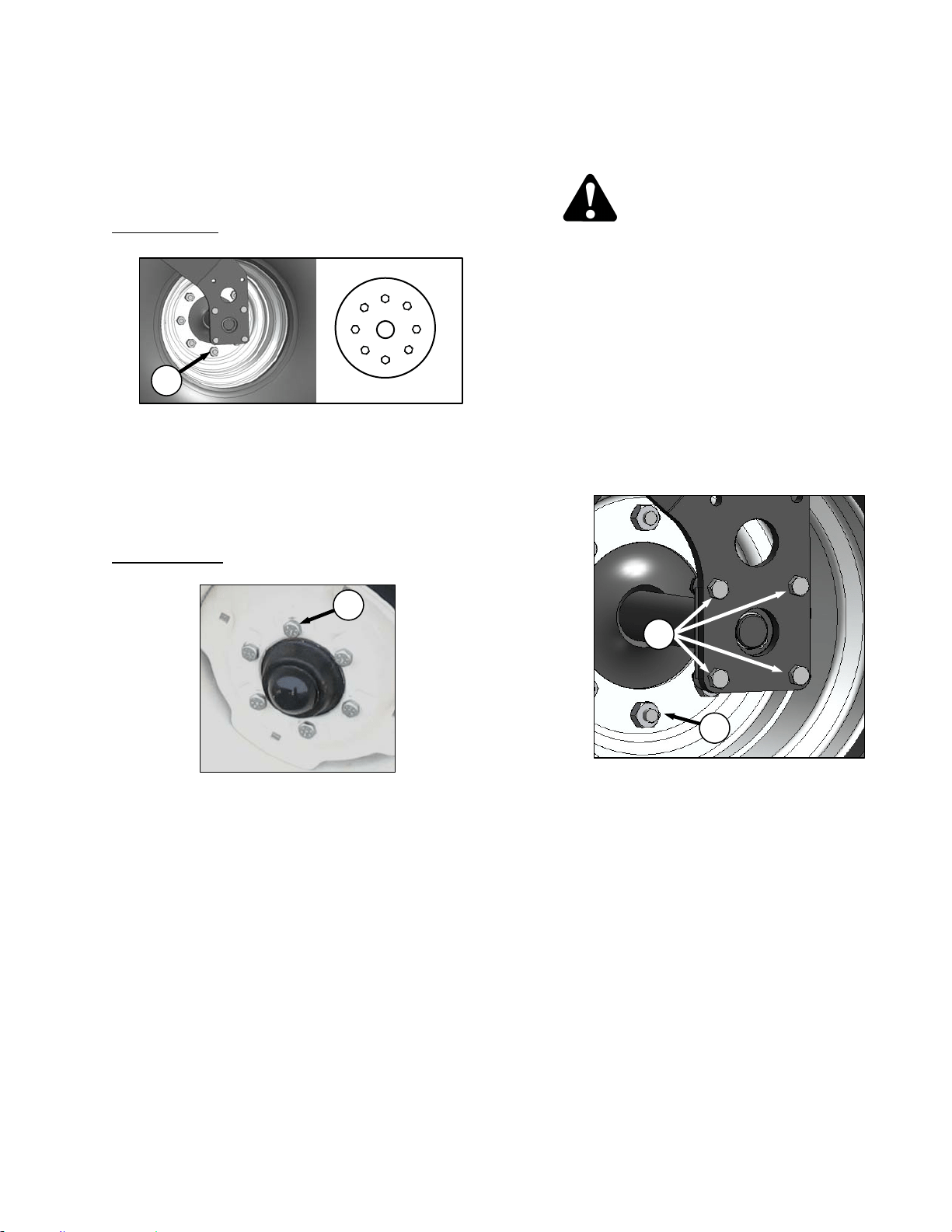
MAINTENANCE/SERVICE
169304 165 Rev. C
57.10.2.3 Wheel Nut Torque
At first use, or when a wheel is removed, check
caster wheel bolt torque as follows after 5 hours
and then at 200 hour intervals:
Forked Casters
a. Tighten nuts (A) to 120 ft·lbf (163 N·m) using the
tightening sequence as shown.
NOTE
To avoid damage to wheel disks, do not
over-tighten wheel nuts.
b. Repeat sequence three times.
Formed Casters
a. Tighten bolts (B) to 120 ft·lbf (163 N·m) using
the tightening sequence as shown.
NOTE
To avoid damage to wheel disks, do not
over-tighten wheel bolts.
b. Repeat sequence three times.
57.10.2.4 Forked Caster Wheel
Removal/Installation
DANGER
To avoid severe personal injury or death
caused by machine runaway, shut off engine
and remove key before performing any of the
following checks and/or adjustments.
a. Remove the caster wheel as follows:
1. Park windrower on level ground and block
all wheels.
2. Place GSL in N-DETENT, shutdown engine
and remove key.
3. Raise end of walking beam using a 2000 lb
(908 kg) capacity jack or other suitable lifting
device until the wheel is slightly off the
ground.
4. Remove the eight bolts (C) attaching axle to
forked caster and remove wheel assembly
from caster.
5. Undo the eight wheel nuts (D) and remove
wheel from axle.
b. Install the caster wheel as follows:
1. Position wheel on axle and install wheel nuts
(D).
2. Torque nuts (D) as specified in previous
section.
3. Position wheel assembly in forked caster
and install with bolts (C). Torque bolts to
75-79 ft·lbf (97-107 N·m).
4. Lower windrower and remove jack.
D
C
1
5
3
2
4
6
B
A
1
5
3
7
8
2
4
6
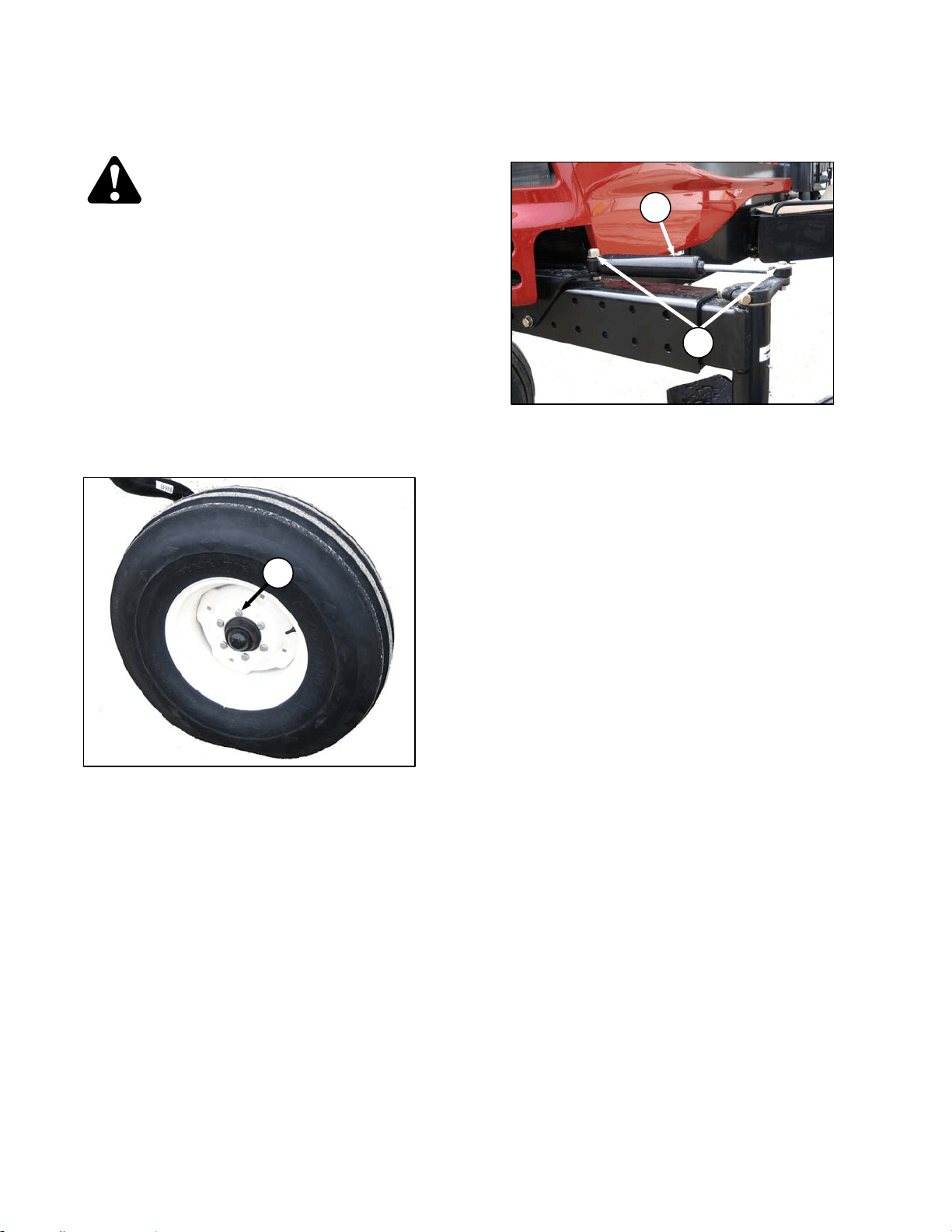
MAINTENANCE/SERVICE
169304 166 Rev. C
57.10.2.5 Formed Caster Wheel
Removal/Installation
DANGER
To avoid severe personal injury or death
caused by machine runaway, shut off engine
and remove key before performing any of the
following checks and/or adjustments.
a. Remove the caster wheel as follows:
1. Park windrower on level ground and block
all wheels.
2. Place GSL in N-DETENT, shutdown engine
and remove key.
3. Raise end of walking beam using a 2000 lb
(908 kg) capacity jack or other suitable lifting
device until the wheel is slightly off the
ground.
4. Undo the six wheel bolts (E) and remove
wheel from hub.
b. Install the caster wheel as follows:
1. Position wheel on hub and install wheel
bolts (E).
2. Torque bolts (E) to 120 ft·lbf (163 N·m) using
the tightening sequence as shown on
previous page.
3. Lower windrower and remove jack.
57.10.2.6 Caster Wheels Anti-Shimmy Dampeners
- Optional
Each caster is equipped with a fluid filled anti-
shimmy dampener (F). The mounting bolts (G)
need to be checked periodically for security.
Refer to Section 7.13, Maintenance Schedule.
Inboard bolt should be tightened to 100 ft·lbf
(135 N·m). Outboard bolt should be tightened to
85 ft·lbf (115 N·m).
F
G
E

MAINTENANCE/SERVICE
169304 167 Rev. C
57.11 MAINTENANCE SCHEDULE
The maintenance schedule (see next page)
specifies the periodic maintenance procedures
and service intervals. Regular maintenance is
the best insurance against early wear and
untimely breakdowns. Following this schedule
will increase machine life. For detailed
instructions, refer to Sections 7.6 to 7.12. Use
the fluids and lubricants specified in Section
7.3.1, Recommended Fuel, Fluids and
Lubricants.
Service Intervals: The recommended service
intervals are in hours of operation. Where a
service interval is given in more than one time
frame, e.g. "100 hours or Annually", service the
machine at whichever interval is reached first.
IMPORTANT
Recommended intervals are for average
conditions. Service the machine more
often if operated under adverse conditions
(severe dust, extra heavy loads, etc.).
CAUTION
Carefully follow safety messages given
under Section 7.1 PREPARATION FOR
SERVICING, and Section 7.2
RECOMMENDED SAFETY PROCEDURES.
57.11.1 Break-In Inspection
HRS ITEM CHECK REF.
Every .25
Road or 1 in
Field
Drive Wheel Nuts
Torque – 220 ft·lbf (300 N·m)
Repeat Checks Until Torque Stabilizes.
7.12.1
5
A/C Belt Tension 7.8.8.3
Caster Wheel Nuts Torque – 120 ft·lbf (163 N·m) 7.12.2
Caster Wheel Anti-Shimmy
Dampener Bolts (Optional)
Inboard Bolt Torque – 100 ft·lbf (135 N·m)
Outboard Bolt Torque – 85 ft·lbf (115 N·m)
Walking Beam Width Adjustment
Bolts (Optional)
Torque – 330 ft·lbf (448 N·m)
6.3.7
10
Walking Beam Width Adjustment
Bolts (Optional)
Torque – 330 ft·lbf (448 N·m)
Drive Wheel Nuts Torque – 220 ft·lbf (300 N·m) 7.12.1
Neutral Dealer Adjust -
50
Hose Clamps – Air
Intake/Radiator/Heater/Exhaust/
Hydraulic
Hand Tighten Unless Otherwise Noted. 7.8.4,
7.8.6,
7.8.7 &
7.3
Walking Beam Width Adjustment
Bolts (Optional)
Torque – 330 ft·lbf (448 N·m) 6.3.7
Caster Wheel Anti-Shimmy
Dampener Bolts (Optional)
Inboard Bolt Torque – 100 ft·lbf (135 N·m)
Outboard Bolt Torque – 85 ft·lbf (115 N·m)
7.12.2
Drive Wheel Nuts Torque 220 ft·lbf (300 N·m) 7.12.1
Drive Wheel Lubricant Change 7.12.1.3
Hydraulic Oil Filters Change 7.11.4

MAINTENANCE/SERVICE
169304 168 Rev. C
57.11.2 Interval Maintenance
INTERVAL SERVICE
FIRST USE
Refer To Break-In Inspection On Previous Page.
ANNUALLY *
1. Change Fuel Tank Vent Line Filter.
2. Check Battery Fluid Level.
3. Check Battery Charge.
4. Check Anti-Freeze Concentration.
5. Cycle A/C Blower Switch To Distribute Refrigerant Oil.
6. Check Safety Systems (or 500 hours whichever occurs first).
END OF
SEASON
Refer To Section 6.3.9 Storage.
10 HOURS OR
DAILY
1. Check Tire Inflation.
2. Check Engine Oil Level.
3. Check Engine Coolant Level At Reserve Tank.
4. Clean Radiator, Hydraulic Oil Cooler, Charge Air Cooler, And A/C Condenser.
5. Check Hydraulic Oil Level.
6. Drain Fuel Filter Water Trap.
7. Fill Fuel Tank.
8. Check Hydraulic Hoses And Lines For Leaks.
50 HOURS
1. Grease Caster Pivots.
2. Grease Walking Beam Center Pivot.
3. Grease Top Lift Link Pivots.
4. Grease Forked Caster Spindle Bearings.
5. Clean Cab Fresh Air Intake Filter.
100 HOURS OR
ANNUALLY *
1. Clean Cab Air Return Filter.
200 HOURS OR
ANNUALLY *
1. Check Drive Wheel Lubricant Level.
2. Grease Formed Caster Wheel Hub Bearings.
3. Check Wheel Nut Torque.
250 HOURS OR
3 MONTHS
1. Change Engine Oil And Filter.
2. Change Engine Air Cleaner Primary Filter Element (CDM displays ENGINE AIR
FILTER).
500 HOURS
1. Change Fuel Filters.
2. Change Hydraulic Oil Filters.
3. Check Engine Valve Tappet Clearance.
1000 HOURS
1. Change Drive Wheel Lubricant.
2. Check Engine Valve Tappet Clearance.
2000 HOURS
1. Change Hydraulic Oil.
2. Perform General Engine Inspection.
3. Change Engine Coolant.
* IT IS RECOMMENDED THAT ANNUAL MAINTENANCE BE DONE PRIOR TO START OF OPERATING
SEASON.

MAINTENANCE/SERVICE
169304 169 Rev. C
WINDROWER Serial No._______________
Combine this record with the record in the Header Operator’s Manual.
Refer to Section 7, Maintenance/Service for details on each maintenance procedure.
Copy this page to continue record.
ACTION:
- Check - Lubricate - Change - Clean + - Add
MAINTENANCE
RECORD
Hour Meter
Reading
Date
Serviced By
FIRST USE Refer to Section 7.13.1 Break-In Inspection
10 HOURS OR DAILY
NOTE: A RECORD OF DAILY MAINTENANCE IS NOT NORMALLY
REQUIRED BUT IS AT THE OWNER/OPERATOR’S DISCRETION.
A/C Condenser
Charge Air Cooler
Engine Oil Level
Engine Coolant Level
Fuel Tank
Fuel Filter Water Trap
Hydraulic Hoses And Lines
Hydraulic Oil Cooler
Hydraulic Oil Level
Radiator
Tire Inflation
ANNUALLY
A/C Blower
Anti-Freeze Concentration
Battery Charge
Battery Fluid Level
Fuel Tank Vent Line Filter
Safety Systems (or 500 hours)
50 HOURS
Cab Fresh Air Intake Filter
Caster Pivots
Forked Caster Spindle Bearings
Top Lift Link Pivots
Walking Beam Center Pivot
100 HOURS OR ANNUALLY
Cab Air Return Filter
200 HOURS OR ANNUALLY
Formed Caster Wheel Hub Bearings
Drive Wheel Lubricant
Wheel Nut Torque
Continued Next Page

MAINTENANCE/SERVICE
169304 170 Rev. C
ACTION:
- Check - Lubricate - Change - Clean + - Add
MAINTENANCE
RECORD
Hour Meter
Reading
Date
Serviced By
250 HOURS OR 3 MONTHS
Engine Oil And Filter
Engine Air Cleaner Primary Filter
Element
500 HOURS
Fuel Filters
Engine Valve Tappet Clearance (1
st
)
Crankcase Breather
Hydraulic Oil Filters
1000 HOURS
Drive Wheel Lubricant
Engine Valve Tappet Clearance
2000 HOURS
Engine Coolant
General Inspection
Hydraulic Oil

TROUBLESHOOTING
* See your MacDon dealer
** Refer to Windrower Technical Manual
169304 171 Rev. C
58 TROUBLESHOOTING
58.1 ENGINE
SYMPTOM PROBLEM SOLUTION SECTION
Engine Hard To Start Or Will Not
Start.
Controls not in neutral. Move GSL to neutral.
Move steering wheel to locked
position.
Disengage header clutch.
6.3.5.1
6.3.5.1
5.16.1
Neutral interlock misadjusted.
Contact MacDon dealer.
*
No fuel to engine. Fill empty fuel tank, replace
clogged filter.
6.3.5.4
7.8.5.2
Old fuel in tank. Drain tank, refill with fresh fuel. 7.8.5.3
Water, dirt or air in fuel system. Drain, flush, fill and prime
system.
7.8.5.3
Improper type of fuel. Use proper fuel for operating
conditions.
7.3.1
Crankcase oil too heavy. Use recommended oil. 7.3.1
Low battery output. Have battery tested. Check
battery electrolyte level.
7.10.1.4
Poor battery connection. Clean and tighten loose
connections.
7.10.1.4
Faulty starter.
Contact MacDon dealer.
*
Wiring shorted, circuit breaker open. Check continuity of wiring and
breaker (manual reset).
7.10.8.1
Loose connection at fuel pump. Ensure connector at pump is
fully pushed in.
-
ECM fuse (1 of 2) blown.
Replace. 7.10.8.2
ECM Ignition relay faulty.
Neutral Logic relay faulty.
Faulty injectors
.
Contact MacDon dealer.
*
Engine Knocks.
Insufficient oil. Add oil. 7.8.2
Engine out of time.
Contact MacDon dealer.
*
Low or high coolant temperature. Remove and check thermostat.
See "Engine Overheats".
**
Improper fuel. Use proper fuel. 7.3.1
Low Oil Pressure.
Low oil level. Add oil. 7.8.2
Improper type of oil. Drain, fill crankcase with proper
oil.
7.8.3
Worn components.
Contact MacDon dealer.
*
High Oil Consumption.
Crankcase oil too light. Use recommended oil. 7.3.1
Oil leaks. Check for leaks around gaskets,
seals, and drain plugs.
7.8.3
Internal parts worn.
Contact MacDon dealer.
*
Engine Runs Irregularly Or Stalls
Frequently.
Unsteady fuel supply. Change filter on fuel tank vent
line. Replace clogged fuel filter.
7.8.5.1
7.8.5.2
Water or dirt in fuel system. Drain, flush, and fill system. 7.8.5.3
Air in fuel system. Contact MacDon dealer. *
Low coolant temperature. Remove and check thermostat. **
Dirty or faulty injectors. Contact MacDon dealer. *
(continued next page)

TROUBLESHOOTING
* See your MacDon dealer
** Refer to Windrower Technical Manual
169304 172 Rev. C
SYMPTOM PROBLEM SOLUTION SECTION
Lack Of Power.
Incorrect timing. Contact MacDon dealer. *
Engine oil viscosity too high. Use recommended oil. 7.3.3
Intake air restriction. Service air cleaner. 7.8.4.1
Clogged fuel filter. Replace primary fuel filter and if
necessary, replace secondary
fuel filter.
7.8.5.2
High back pressure. Clean out muffler. 7.8.7
Improper type of fuel. Use proper fuel. 7.3.1
High or low engine temperature. Remove and check thermostat.
See "Engine Overheats".
**
Improper valve clearance.
Contact MacDon dealer.
*
Faulty injectors. Contact MacDon dealer. *
Engine Temperature Below
Normal.
Defective thermostat. Remove and check thermostat.
*
Warning Alarm Sounds.
Engine overheated. Check coolant level. 7.8.6.1
Check thermostat. **
Low engine oil pressure. Check oil level.
Check oil level.
7.8.2
Low transmission oil pressure. 7.8.2
Engine Overheats.
Low coolant level. Fill reserve tank to proper level.
Check system for leaks.
7.8.6.1
Engine overloaded. Reduce ground speed. 6.3.6.2
Defective radiator cap. Replace cap. 7.8.6.2
Defective fan belt. Replace belt. 7.8.8.3
Dirty radiator screen:
• Rotors turning
Check for obstructions in ducting
from screen to fan shroud.
7.10.1
• Rotors not turning
Check connections to rotor
electric motor.
Dirty radiator core. Clean radiator. 7.10.2
Cooling system dirty. Flush cooling system. 7.8.6.3
Defective thermostat. Remove and check thermostat. **
Defective temperature gauge or
sender.
Check coolant temperature with
thermometer, replace if
necessary.
7.8.6.2
Defective water pump.
Contact MacDon dealer.
*
Use antifreeze. 7.8.6.1
Engine RPM Cannot Exceed
2400.
ISC engaged. Disengage ISC
5.18.5
High Fuel Consumption.
Improper type of fuel. Use proper fuel. 7.3.1
Clogged or dirty air cleaner. Service air cleaner. 7.8.4.1
Engine overloaded. Reduce ground speed. 6.3.6.2
Improper valve clearance. Reset valves. *
Engine out of time. Contact MacDon dealer. *
Low engine temperature. Check thermostat. **
Injection nozzles dirty. Contact MacDon dealer. *
(continued next page)

TROUBLESHOOTING
* See your MacDon dealer
** Refer to Windrower Technical Manual
169304 173 Rev. C
SYMPTOM PROBLEM SOLUTION SECTION
Engine Emits Black Or Grey
Exhaust.
Improper type of fuel. Consult your fuel supplier and
use proper type fuel for
conditions.
7.3.1
Engine overloaded. Reduce ground speed. 6.3.6.2
Clogged or dirty air cleaner. Service air cleaner. 7.8.4.1
Defective muffler. Check muffler for possible
damage which might create back
pressure.
7.8.7
Dirty or faulty injectors.
Contact MacDon dealer. *
Engine out of time.
Air in fuel system.
Engine Emits White Exhaust.
Improper type of fuel. Consult your fuel supplier and
use proper type fuel for
conditions.
7.3.1
Cool engine. Warm engine up to normal
operating temperature.
6.3.5.2
Defective thermostat. Remove and check thermostat. **
Engine out of time. Contact MacDon dealer. *
Starter Cranks Slowly Or Will
Not Operate.
Low battery output. Check battery charge. 7.10.1.1
Controls not in neutral. Move GSL to neutral.
Move steering wheel to center
position.
Disengage header clutch.
6.3.6
6.3.5.1
5.16.1
Relay not functioning. Check relay and wire
connections.
7.10.8.1
Loose or corroded battery
connections.
Clean and tighten loose
connections.
7.10.1.4
Key switch worn or terminals loose.
Contact MacDon dealer.
*
Crankcase oil too high viscosity. Use recommended oil. 7.3.3
Main fuse defective/blown. Replace main fuse. 7.10.8
Key power fuse blown. Replace. 7.10.8
Switch at interlock not closed or
defective.
Adjust switch or replace.
*
Air Filters Require Frequent
Cleaning.
Vacuator plugged. Clean out vacuator.
7.8.4.1
Pre-cleaner rotor not turning freely. Repair/replace. 7.10.1
58.2 ELECTRICAL
SYMPTOM PROBLEM SOLUTION SECTION
Low Voltage And/Or Battery Will
Not Charge.
Defective battery. Have battery tested.
7.10.1.4
Defective alternator belt. Replace worn belt. 7.8.8.2
Loose or corroded connections. Clean and tighten battery
connections.
7.10.1.4
Dirty or defective alternator,
defective voltage regulator, or high
resistance in circuit.
Contact MacDon dealer.
*
Alternator or voltage regulator not
connected properly.
Connect properly.
7.10.1.6
(continued next page)

TROUBLESHOOTING
* See your MacDon dealer
** Refer to Windrower Technical Manual
169304 174 Rev. C
SYMPTOM PROBLEM SOLUTION SECTION
Lights Dim.
High resistance in circuit or poor
ground on lights.
Check the wiring circuit for a
break in a wire or a poor ground.
---
Defective light switch.
Contact MacDon dealer.
*
Lights Do Not Light.
Burnt out light bulb. Replace light bulb. 7.10.2 to
7.10.9
Defective light switch.
Contact MacDon dealer.
*
Broken wiring. Check wiring for broken wire or
shorts.
---
Open or defective circuit breaker. Check circuit breaker.
7.10.8.1
Defective relay. Replace relay.
Poor ground on lights.
Clean and tighten ground wires.
---
Turn Signals Or Indicators
Showing Wrong Direction.
Reversed wires.
Contact MacDon dealer.
*
No Current To Cab.
Circuit breaker tripped. Breaker automatically resets. ---
Broken or disconnected wire.
Contact MacDon dealer.
*
58.3 HYDRAULICS
SYMPTOM PROBLEM SOLUTION SECTION
Header Or Reel Not Lifting.
Contaminant in relief valve. Clean relief valve at cylinder
control valve.
**
Appropriate solenoids not being
energized by activating switch.
Contact MacDon dealer.
*
Header Or Reel Lifts But Lacks
Power.
Relief pressure too low or
contaminant in relief valve.
Check/adjust/clean relief valve at
cylinder control valve.
**
Reel And/Or Conveyor Not
Turning.
Header drive switch not engaged. Engage switch.
5.16.1
Flow controls adjusted too low. Toggle speed controls on CDM
to increase flow.
6.5.3,
6.5.4, 6.6.4
Appropriate solenoid on flow control
block not being energized.
Contact MacDon dealer.
*
Reel And/Or Conveyor Turns But
Lacks Power.
Relief pressure too low. Check/adjust/clean compensator
pump.
**
58.4 HEADER DRIVE
SYMPTOM PROBLEM SOLUTION SECTION
Sickle Drive Not Engaging.
Header drive switch in cab not
engaged.
Engage switch.
5.16.1
Appropriate solenoid not being
energized by activating switch.
Contact MacDon dealer.
*
Operator presence switch not
closed or faulty.
Occupy operator’s seat or
replace switch.
*
Sickle Drive Lacks Power
Header drive overload. Reduce ground speed. 6.3.6.2
Pressure too low or contaminant in
pump compensator valve.
Check/adjust/clean compensator
valve on knife drive pump.
*
Warning Alarm Sounds
Header drive overload. Reduce ground speed. 6.3.6.2
Compensator valve setting too low.
Adjust compensator valve on knif
e
drive pump.
*

TROUBLESHOOTING
* See your MacDon dealer
** Refer to Windrower Technical Manual
169304 175 Rev. C
58.5 TRACTION DRIVE
SYMPTOM PROBLEM SOLUTION SECTION
Warning Alarm Sounds And
Transmission Oil Light Is On.
Low hydraulic oil level. Stop engine and add oil to
hydraulic system.
7.12.1
Low hydraulic pressure.
Contact MacDon dealer.
*
Foreign material shorting sender.
Short in alarm wiring.
Faulty sender.
Wheels Lack Pulling Ability On A
Grade Or Pulling Out Of A Ditch.
Insufficient torque at drive wheels. Move speed-range control to
field position and reduce ground
speed.
6.3.6
Loose or worn controls. Check controls. 7.8.3
Air in system. Use proper oil. 7.3.3
Check oil level, and leaks. 7.11.1
Check oil filters.
7.11.4
Brakes binding or not releasing fully. Check pressure (min. 200 psi
(1379 kPa)) on brake release
valve.
**
Internal pump or motor damage.
Contact MacDon dealer.
*
Relief valve in tandem pump dirty or
damaged.
Replace relief valve. **
Both Wheels Will Not Pull In
Forward Or Reverse.
Low oil level. Check oil reservoir level. 7.11.1
Power hubs disengaged. Engage power hubs. 6.3.8.4
Damaged hydraulic lines preventing
proper oil flow.
Replace damaged lines. *
Steering controls worn or defective. Check GSL and steering for
loose, worn or dam-aged ball
joints and connecting rods.
7.7.3 &
7.7.4
Speed-range control not working.
Contact MacDon dealer.
*
Pump arms have broken shaft or
loose hardware.
Repair or tighten. **
Brakes binding or not releasing fully.
Check pressure (min. 200 psi
(1379 kPa)) on brake release
valve.
**
Charge pressure relief valve
misadjusted or damaged.
Check the valve adjustment.
Check valve parts and seat.
7.11.6.2
Failed pump or motor.
Contact MacDon dealer.
*
One Wheel Does Not Pull In
Forward Or Reverse.
One final drive disengaged. Engage final drive. 6.3.8.3
Pump arm or shaft are broken.
Contact MacDon dealer.
*
Steering controls worn or defective. Check GSL and steering for
loose, worn or damaged ball
joints and connecting rods.
7.7.3 &
7.7.4
Damaged hydraulic lines preventing
proper oil flow.
Contact MacDon dealer.
*
Brakes binding or not releasing fully.
Check pressure (min. 200 psi on
brake release valve.
**
Speed-range control not working.
Contact MacDon dealer.
*
(continued next page)

TROUBLESHOOTING
* See your MacDon dealer
** Refer to Windrower Technical Manual
169304 176 Rev. C
SYMPTOM PROBLEM SOLUTION SECTION
One Wheel Does Not Pull In
Forward Or Reverse
(Continued).
High pressure relief valve stuck
open, damaged seat.
Check valve and clean or
replace.
**
Failed pump, motor or power hub.
Contact MacDon dealer.
*
With Steering Wheel Centered,
One Wheel Pulls More Than The
Other.
Leakage at pump or motor.
Contact MacDon dealer.
*
Wheels not in same speed range.
Faulty relief valve. Repair or replace valve. 7.11.6.2
Excessive Noise From Drive
System.
Hydraulic line clamps loose. Tighten clamps. ---
Mechanical interference in steering
or ground speed linkage.
Adjust, repair, replace. 7.7.3 &
7.7.4
Brakes binding or not releasing fully. Check pressure (min. 200 psi on
brake release valve.
**
Faulty pump or motor.
Contact MacDon dealer.
*
Air in system. Check lines for leakage. ---
Hydraulic Oil Filter Leaks At
Seal.
Not properly tightened. Tighten filter element. 7.11.4
Damaged seal or threads. Replace filter or filter head. 7.11.4
58.6 STEERING AND GROUND SPEED CONTROL
SYMPTOM PROBLEM SOLUTION SECTION
Machine Will Not Steer Straight.
Linkage worn or loose. Adjust steering chain tension.
Replace worn parts, adjust
linkage.
7.7.4.2
7.7.4.1
Machine Moves On Flat Ground
With Controls In Neutral.
Neutral interlock misadjusted.
Contact MacDon dealer.
*
Parking brake not functioning.
Insufficient Road Speed.
Speed-range control in field
position.
Move to road position. 6.3.8.1
Steering Wheel Will Not Lock
With GSL In N-DETENT.
Transmission interlock misadjusted.
Contact MacDon dealer.
*

TROUBLESHOOTING
* See your MacDon dealer
** Refer to Windrower Technical Manual
169304 177 Rev. C
58.7 CAB AIR
SYMPTOM PROBLEM SOLUTION SECTION
Blower Fan Will Not Run.
Burned out motor.
Contact MacDon dealer.
*
Burned out switch.
Motor shaft tight or bearings worn.
Faulty wiring - loose or broken.
Blower rotors in contact with
housing.
Blower Fan Operating But No Air
Coming Into Cab.
Dirty fresh air filter. Clean filter. 7.7.5.1
Dirty recirculating air. Clean filter. 7.7.5.2
Evaporator clogged. Clean evaporator. 7.7.5.4
Air flow passage blocked. Remove blockage. ---
Heater Not Heating.
Heater shut-off valve at engine
closed.
Open valve.
5.10.1.1
Defective thermostat in engine
water outlet manifold.
Replace thermostat.
**
Heater temperature control
defective.
Replace control.
**
No thermostat in engine water outlet
manifold.
Install thermostat.
**
Odour From Air Louvers.
Plugged drainage hose. Blow out hose with compressed
air.
---
Dirty filters. Clean filters. 7.7.5.1 &
7.7.5.2
Air Conditioning Not Cooling.
Low refrigerant level. Add refrigerant *
Switch contacts in thermostat
burned excessively, or sensing
element defective.
Replace thermostat.
**
Clutch coil burned out or
disconnected.
Contact MacDon dealer.
*
Condenser fins plugged. Clean condenser. 7.9.2
Blower motor disconnected or
burned out.
Contact MacDon dealer.
*
Loose or broken drive belt. Replace drive belt and/ or tighten
to specs.
7.8.8.4
Compressor partially or completely
seized.
Remove compressor for service
or replacement.
**
Dirty filters. Clean fresh air and re-circulation
filters.
7.7.5.1 &
7.7.5.2
Broken or disconnected electrical
wire.
Check all terminals for loose
connections; check wiring for
hidden breaks.
---
Broken or disconnected ground
wire.
Check ground wire to see if
loose, broken, or disconnected.
---
Expansion valve stuck in open or
closed position.
Contact MacDon dealer.
*
Broken refrigerant line.
Leak in system.
(continued next page)

TROUBLESHOOTING
* See your MacDon dealer
** Refer to Windrower Technical Manual
169304 178 Rev. C
SYMPTOM PROBLEM SOLUTION SECTION
Air Conditioning Not Cooling.
(Continued)
Compressor shaft seal leaking.
Contact MacDon dealer.
*
Clogged screen in receiver-drier;
plugged hose or coil.
Air Conditioning Not Producing
Sufficient Cooling.
(Sufficient Cooling Defined As
When Air Temperature In Cab,
Measured At Louvered Vent, Can
Be Maintained At 25°F (14°C)
Below Ambient Air Temperature.)
Compressor clutch slipping. Remove clutch assembly for
service or replacement.
**
Clogged air filters. Remove air filters and clean or
replace as necessary.
7.7.5.1 &
7.7.5.2
Heater circuit is open. Close heater valves (1 in cab, 1
at engine).
5.10.1.1
Too little air circulation over
condenser coil; fins clogged with dirt
or insects.
Clean condenser.
7.9.7.3
Evaporator fins clogged. Clean evaporator fins (under cab
floor).
7.7.5.4
Too little refrigerant in system.
Contact MacDon dealer.
*
Clogged expansion valve.
Clogged receiver-drier.
Excessive moisture in system.
Air in system.
Thermostat defective or improperly
adjusted.
Replace thermostat.
**
Blower motor sluggish in operation.
Contact MacDon dealer.
*
Air Conditioning System Too
Noisy.
Defective winding or improper
connection in compressor clutch coil
or relay.
Contact MacDon dealer.
*
Loose or excessively worn drive
belt.
Tighten or replace as required.
7.8.8.4
Noisy clutch. Remove clutch for service or
replacement as required.
**
Noisy compressor. Check mountings and repair.
Remove compressor for service
or replacement.
**
Compressor oil level low. Add SP-15 PAG refrigerant oil. **
Blower fan noisy due to excessive
wear.
Remove blower motor for service
or replacement as necessary.
**
Excessive charge in system.
Contact MacDon dealer.
*
Low charge in system.
Contact MacDon dealer.
*
Excessive moisture in system.
(continued next page)

TROUBLESHOOTING
* See your MacDon dealer
** Refer to Windrower Technical Manual
169304 179 Rev. C
SYMPTOM PROBLEM SOLUTION SECTION
Air Conditioning Cools
Intermittently.
Compressor clutch slipping.
Contact MacDon dealer.
*
Unit icing up due to:
• Thermostat adjusted too low.
Adjust thermostat.
**
• Excessive moisture in system.
Contact MacDon dealer.
*
• Incorrect super-heat
adjustment in expansion valve.
Thermostat defective.
Defective blower switch or blower
motor.
Partially open, improper ground or
loose connection in compressor
clutch coil.
Windows Fog Up.
High humidity. Run A/C to dehumidify air and
heater to control temperature.
5.10.1.1
58.8 OPERATOR’S STATION
SYMPTOM PROBLEM SOLUTION SECTION
Rough Ride.
Seat suspension not adjusted for
operator's weight.
Adjust seat suspension.
5.3
High air pressure in tires. Deflate to proper pressure. 7.12.1 &
7.12.2

OPTIONS
169304 180 Rev. C
59 OPTIONS
59.1 REEL DRIVE & LIFT PLUMBING
Reel drive and lift plumbing for draper headers
on windrowers that are shipped from the factory
in auger header configuration. Installation
instructions are included.
59.2 WINDROWER HYDRAULIC
COMPLETION FOR DRAPER
HEADER REEL FORE/AFT
Allows reel fore/aft hydraulic adjustment for
draper headers on windrowers that are shipped
from the factory in auger header configuration.
Kit includes valve for selection of reel fore/aft or
double windrow attachment functions.
Installation instructions are included.
59.3 BOOSTER SPRING KIT
Available for headers over 6000 lb (2724 kg).
Installation instructions are included.
59.4 INTERNAL BOOSTER SPRING KIT
Internal spring for right side lift linkage to
improve float capacity. Standard equipment on
left side. Installation instructions are included.
59.5 LIGHT HEADER FLOTATION KIT
Available for headers that do not require as
much spring tension for float. Installation
instructions are included.
59.6 AM-FM RADIO
Available for installation into pre-wired cab.
Speakers are factory installed.
Refer to M100 Self-Propelled Windrower
Unloading and Assembly Instructions supplied
with your windrower for installation details.
59.7 HYDRAULIC CENTER LINK
The hydraulic center link allows the operator to
adjust the header angle from the cab.
Installation instructions are included.
59.8 FAN AIR BAFFLE KIT
Provides a baffle to reduce windrow disturbance
by air exiting the engine cooling fan.
59.9 TRAINING SEAT
A wall mounted fold-up training seat complete
with seat belt is available to assist in training a
new operator. Installation instructions are
included.
59.10 KNIFE SPEED, REEL SPEED
INDEX, AND TILT SENSOR
MODULE
To allow the electronic monitoring of header
knife speed, reel speed and header angle. Also
enables the indexing of reel speed to ground
speed. Installation instructions are included.
59.11 ANTI-SHIMMY KIT FOR CASTERS
Prevents caster wheel shimmy when traveling at
road speed.
59.12 SWATH ROLLER
If a swath roller is desired for canola or other
similar crops, an axle mounted design is
recommended. Windrower can be fitted with
hydraulic lift version of swath rollers featuring in
console controls.
59.13 WARNING BEACONS
Two roof mounted rotating warning beacons are
available for installation into pre-wired cab. The
beacons are standard equipment for export
windrowers and optional for North America.
Installation instructions are included.
59.14 AUTO-STEER
A MacDon approved auto-steer system is
available for your windrower. Contact your
dealer for further information.
Cabs have been prepared with “access routing
knock outs” to enable easy wiring harness
installation and display mounting. The GSL has
been pre-wired with an auto-steer engage
switch.
59.15 ENGINE BLOCK HEATER
Contact your nearest Cummins Engine
Distributor and provide your engine model and
serial numbers to ensure the proper heater is
supplied.
(continued next page)

OPTIONS
169304 181 Rev. C
59.16 TRANSPORT DRAWBAR
Allows an M100 Windrower to tow MacDon headers
equipped with a Slow Speed Transport system.
Includes drawbar, related parts, and installation
instructions.

INDEX
169304 182 Rev. C
Abbreviations .................................................................. 12
Air Cleaner ....................................................................120
Air Conditioning
compressor protection ........................................ 23, 117
condenser ......................................................... 116, 136
controls ...................................................................... 22
evaporator ................................................................116
operation ...................................................................117
troubleshooting .........................................................176
Alternator .......................................................................142
Anti-freeze ...................................................................... 99
Attachments ..................................................................179
Auger Header
attachment ................................................................. 89
auger speed ............................................................... 94
detaching ................................................................... 92
reel speed .................................................................. 95
Auxiliary Power ............................................................... 23
Ballast
caster wheels ............................................................163
Battery ...........................................................................138
adding electrolyte .....................................................140
boosting ....................................................................139
charging ....................................................................139
maintenance .............................................................138
replacement ..............................................................141
Belts
compressor ...............................................................133
fan ............................................................................132
Break-In Period .............................................................. 47
Cab
air vents ..................................................................... 22
ingress/egress ........................................................... 54
interior lighting ........................................................... 23
operator amenities ..................................................... 23
radio........................................................................... 24
Cab Air Filters
servicing ........................................................... 115, 116
Cab Display Module .................................................. 30, 31
Cab Forward ................................................................... 55
Cab Temperature ........................................................... 22
Capacities ....................................................................... 99
Caster Wheels ...............................................................162
anti-shimmy ..............................................................165
ballast .......................................................................163
bolt torque .................................................................164
removal/installation ........................................... 164, 165
tread adjustment ........................................................ 57
CDM ............................................................................... 30
CDM Displays ................................................................. 31
Circuit Breakers .............................................................149
Compressor Oil .............................................................. 99
Console .......................................................................... 16
Cooler ............................................................................. 23
Daily check ..................................................................... 48
Deck Shift Switch ........................................................... 29
Dimensions ..................................................................... 13
Display
set-up
......................................................................... 42
Display Warnings ........................................................... 37
Draper Header
attachment ................................................................. 77
deck shift ................................................................... 88
detaching .................................................................... 80
draper speed .............................................................. 85
knife speed ........................................................... 87, 96
reel speed ................................................................... 83
Drawbar ........................................................................... 63
swath roller ................................................................. 65
Drive Wheels ................................................................. 159
bolt torque ................................................................ 159
lubricant .................................................................... 160
removal/installation ................................................... 161
Driving
roads .......................................................................... 58
spin turn ...................................................................... 56
stopping ...................................................................... 56
windrower ................................................................... 53
Electrical System
circuit breakers ......................................................... 149
fuses ......................................................................... 149
main fuses ................................................................ 151
troubleshooting ......................................................... 172
Engine
air filters .................................................................... 120
alternate speeds ................................................. 52, 133
battery ...................................................................... 138
battery maintenance ................................................. 138
belt replacement ....................................................... 133
belt tension ............................................................... 132
break-in ...................................................................... 47
changing oil .............................................................. 119
charge air ................................................................. 122
exhaust ..................................................................... 131
fan belt ...................................................................... 132
fuel ...................................................... See Fuel System
inspection ................................................................. 118
monitoring ................................................................... 30
oil level ..................................................................... 118
oil pressure ................................................................. 52
operating temperature ................................................ 51
operation .................................................................... 49
speed adjustment ..................................................... 133
starting ........................................................................ 49
throttle adjustment .................................................... 133
troubleshooting ......................................................... 170
voltage ........................................................................ 52
warm-up ..................................................................... 50
warning lights ....................................................... 36, 52
Engine Cooling System ................................................. 128
changing coolant ...................................................... 129
coolant level & concentration .................................... 128
cooling box servicing ................................................ 136
radiator screen.......................................................... 134
Engine Electrical System
damage prevention ................................................... 142
Engine Hood ................................................................. 103
Engine Lock-out
checks ...................................................................... 107
Error Codes ................................................................... 185
Exhaust ......................................................................... 131
Fan Belt
replacement .............................................................. 132
tension ...................................................................... 132
Field Lights .................................................................... 143
Final Drive ....................................................................... 68

INDEX
169304 183 Rev. C
Float ................................................................................ 70
Float Adjustment ............................................................. 70
Flood Lights .......................................................... 144, 145
Fuel ................................................................................. 99
Fuel System
filters ......................................................................... 124
priming ..................................................................... 127
separator .................................................................. 126
supply valve .............................................................. 125
tank venting .............................................................. 123
Fuel Tank
draining .................................................................... 125
Fueling ............................................................................ 51
Fuses ............................................................................ 149
Gauges ........................................................................... 25
Ground Speed
control lever ................................................................ 26
range switch ............................................................... 26
GSL
fore/aft ...................................................................... 108
position ..................................................................... 110
GVW
allowables................................................................... 60
Hazard Warning Lights .................................................... 26
Header
angle adjustment ........................................................ 74
attaching draper ......................................................... 77
detaching draper ........................................................ 80
drive ........................................................................... 73
drop rate ................................................................... 156
engage ....................................................................... 73
float adjustment .......................................................... 70
float switch.................................................................. 29
flotation ....................................................................... 70
functions ..................................................................... 30
height control .............................................................. 75
levelling ...................................................................... 72
lift cylinder stops ......................................................... 69
monitoring................................................................... 30
on/off switch ............................................................... 27
operation .................................................................... 69
position switch ............................................................ 28
programming .............................................................. 39
return to cut ................................................................ 75
reverse ....................................................................... 73
stand .......................................................................... 79
troubleshooting ......................................................... 173
Header Control Switches .......................................... 27, 29
Header Controls .............................................................. 27
Heater
controls ....................................................................... 22
shut-off valve .............................................................. 22
Height Control ................................................................. 75
Hub Locks ....................................................................... 68
Hydraulic System .......................................................... 152
charge pump pressure ............................................. 157
oil changing .............................................................. 154
oil cooler ................................................................... 154
oil filter ...................................................................... 154
oil level ..................................................................... 152
relief pressure ........................................................... 155
traction drive ............................................................. 157
transmission oil pressure .......................................... 157
troubleshooting ......................................................... 173
valve block ............................................................... 155
Hydraulics
hoses and lines ........................................................ 158
leaks ......................................................................... 158
Ignition Switch ................................................................. 25
Interior Lights ................................................................ 148
Jacking .......................................................................... 161
Knife Drive
valve block ............................................................... 155
Knife Speed
draper header ............................................................. 96
Levelling the Header ....................................................... 72
Lift Cylinder Stops ........................................................... 69
Lighting
engine forward ........................................................... 20
road ............................................................................ 58
Lights .............................................................................. 19
floodlight bulb replace .............................................. 144
headlight adjustment ................................................ 143
headlight bulb ........................................................... 143
rear flood .................................................................. 145
red tail ...................................................................... 147
swath ........................................................................ 146
Lubricants ....................................................................... 99
Lubrication .................................................................... 105
Maintenance Platforms ................................................. 104
Maintenance Record ..................................................... 168
Maintenance Schedule ................................................. 166
Manual Storage ............................................................... 23
Monitoring System .......................................................... 31
Neutral Set-Up .............................................................. 113
Neutral Start Switch ...................................................... 111
Oil Cooler ...................................................................... 136
Oil Filter......................................................................... 119
Operating Screens .......................................................... 31
Operator's Console ......................................................... 16
Operator's Presence ....................................................... 18
checks ...................................................................... 107
engine ........................................................................ 18
header drive ............................................................... 18
transmission ............................................................... 18
Operator's Station ........................................................... 16
troubleshooting ......................................................... 178
Options ......................................................................... 179
Owner/Operator Responsibilities .................................... 45
Pre-Season Check .......................................................... 48
Programming .................................................................. 39
Radiator Cap ................................................................. 129
Radio .............................................................................. 24
Rear View Mirrors ........................................................... 21
Reel
position switch ............................................................ 28
speed switch .............................................................. 28
Refrigerant ...................................................................... 99
Relief Valve ................................................................... 157
Return to Cut ................................................................... 75
Rotors
screen cleaners ........................................................ 134
Safety
general ....................................................................... 10
operation .................................................................... 47
procedures ................................................................. 98
signal words ................................................................. 5
signs ............................................................................. 5

INDEX
169304 184 Rev. C
symbols ....................................................................... 5
Seat Adjustment ............................................................. 16
Seat Belts ....................................................................... 17
maintenance .............................................................107
Serial Number .................................................................. 1
Servicing
preparation ................................................................ 98
Signal Lights ..................................................................148
Specifications ............................................................ 13, 14
Starting Engine ............................................................... 49
Steering Column Adjust .................................................. 17
Storage
fuel and lubricants ..................................................... 99
windrower .................................................................. 68
Swath Lights ..................................................................146
Symbol Definitions .......................................................... 45
Tail Lights ......................................................................147
Tire Inflation
caster wheels ............................................................162
drive wheels ..............................................................159
Torques .........................................................................100
Tow-Bar
attachment ................................................................. 63
Towing
electrical .................................................................... 64
header ....................................................................... 60
Towing Windrower .......................................................... 67
Traction drive
neutral start switch ....................................................111
Traction Drive
adjustments ..............................................................108
cable tension ............................................................110
GSL fore/aft ..............................................................108
GSL position .............................................................110
hub locks .................................................................... 68
neutral interlock ........................................................ 108
neutral lock ............................................................... 111
neutral set-up procedure .......................................... 113
troubleshooting ................................................. 174, 175
Training Seat ................................................................... 17
Transport Mode ............................................................... 61
Transporting .................................................................... 58
Troubleshooting
air conditioning ......................................................... 176
electrical ................................................................... 172
engine ....................................................................... 170
header drive ............................................................. 173
hydraulics ................................................................. 173
operator's Station ..................................................... 178
traction drive ............................................................. 174
Turn Signals .................................................................... 26
Warnings
engine ......................................................................... 36
Water In Fuel Sensor .................................................... 120
WCM ............................................................................... 31
Weight Box ...................................................................... 62
Wheel Bolt Torque................................................. 159, 164
Windrower
break-in ...................................................................... 48
dimensions ................................................................. 13
driving ......................................................................... 53
driving on road ............................................................ 58
electrical ...................................... See Electrical System
monitoring ................................................................... 30
specifications .............................................................. 14
towing ......................................................................... 67
transporting ................................................................ 58
Windshield Wipers........................................................... 21

CDM/WCM FAULT CODES
169304 185 Rev. C
E 1
E 2
R
TCH NOT
A
LLOWED
Return To Cut activated with the header off.
E 3
E 4
E 5
E 6
TEMP G
A
UGE SHO
R
T
Wirin
g
/ connection
p
roblem.
E 7
SPEED ST I CK SHO
R
T
Wirin
g
/ connection
p
roblem.
E 8
HE
A
DE
R
EN
A
BLE SHO
R
T
Wirin
g
/ connection
p
roblem.
E 9
E 10
CDM I NTE
R
N
A
LE
R
R
O
R
Internal hardware or software
p
roblem.
E 11
CDM POWE
R
UP
CDM Module did not
p
ower u
p
correctl
y
.
E 12
E 13
FUEL SOLENO I D
WCM Fuel solenoid out
p
ut fault detected.
E 14
E 15
KN I FE D
R
I
V
EPWM
V
8
Knife drive - PWM solenoid drive fault detected.
E 16
D
R
A
PE
R
D
R
V
PWM
V
9
A
Dra
p
er Drive - PWM solenoid drive fault detected.
E 17
R
EEL D
R
I
V
EPWM
V
9B
Reel Drive - PWM solenoid drive fault detected.
E 18
E 19
E 20
E 21
E 22
E 23
E 24
E 25
E 26
E 27
E 28
TILT
R
ET
R
A
CT
V
2B
Tilt retract solenoid V2B fault detected.
E 29
TILT E
X
TEND
V
2
A
Tilt extend solenoid V2A fault detected.
E 30
4W
A
Y
V
A
L
V
E
V
6
4 Wa
y
valve V6 fault detected.
E 31
B
Y
P
A
SS
V
A
L
V
E
V
1
B
yp
ass valve V1 fault detected.
E 32
HE
A
DE
R
UP
/
DOWN
V
4
A
Header u
p
/ down solenoid V4A fault detected.
E 33
SC
R
EEN CLE
A
NE
R
S
Screen cleaner out
p
ut fault detected
(
shorted or o
p
en
)
.
E 34
R
IGHT STOP L
A
MP
Ri
g
ht sto
p
lam
p
out
p
ut fault detected
(
shorted or o
p
en
)
.
E 35
LEFT STOP L
A
MP
Left sto
p
lam
p
out
p
ut fault detected
(
shorted or o
p
en
)
.
E 36
R
IGHT TU
R
NL
A
MP
Ri
g
ht turn lam
p
out
p
ut fault detected
(
shorted or o
p
en
)
.
E 37
LEFT TU
R
NL
A
MP
Left turn lam
p
out
p
ut fault detected
(
shorted or o
p
en
)
.
E 38
M
A
IN D
R
I
V
E
V
10
Main header drive solenoid V10 fault detected.
E 39
E 40
HIGH
R
A
NGE
V
5
A
Hi
g
h ran
g
e solenoid V5A fault detected.
E 41
R
EEL
A
FT
V
2B
Reel aft solenoid V2B fault detected.
E 42
R
EEL FO
R
E
V
4D
Reel fore solenoid V4D fault detected.
E 43
R
EEL UP
/
DOWN
V
4B
Reel u
p
/ down solenoid V4B fault detected.
E 44
E 45
E 46
SENSO
R
V
OLTS H I GH
Sensor volta
g
e out
p
ut hi
g
h.
E 47
SENSO
R
V
OLTS LOW
Sensor volta
g
e out
p
ut low.
E 48
E 49
E 50
B
A
TT+ OUT OF
R
A
NGE
S
y
stem volta
g
e above 16.5 VDC.
E 51
E 64
E 65
E 66
## . # LOW
V
OLTS
Low s
y
stem volta
g
e <11.5 VDC
E 67
T
R
A
NS O I L P
R
ESSU
R
E
Drive char
g
e
p
ressure low
E 68
T
R
A
NS O I L TEMP
Trans oil tem
p
>221 de
g
F.
E 69
E 70
E 71
LOW H
Y
D
R
A
UL I C OI L
Low h
y
draulic oil level sensor tri
pp
ed
E 72
## . # HIGH
V
OLTS
S
y
stem volta
g
e above
E101
SP I E
R
R
O
R
J1939 Can error
E102
C
A
NE
R
R
O
R
J1939 Can error
E103
EEP
R
OM
R
E
A
DE
R
R
O
R
Internal erro
r
E104
EEP
R
OM W
R
ITE E
R
R
O
R
Internal erro
r
E105
TEMP SENSO
R
E
R
R
O
R
Internal tem
p
erature sensor error.
ENG I NE O I L P
R
ESSU
R
E
En
g
ine oil
p
ressure warnin
g
.
ENG I NE TEMPE
R
A
TU
R
E
En
g
ine coolant tem
p
erature warnin
g
.
C
A
NBUSS E
R
R
O
R
NO OPERATOR
Operator not detected in seat (~3 second delay before message)
NO HEADER
No header ID detected - not hooked up or wiring error.
DISENGAGE HEADER
Header engage switch on when ignition turned on.
SFC
Engine code configuration (Canbus)
CENTER STEER I NG
GSL or Pintal switches not closed with the key on / engine off.
NOT I N PARK
GSL or Pintal switches not closed with the key on / engine off.
CDM / WCM FAULT CODES
MISC INFORMATION / ERROR CODES
Error codes E52 to E63 not allocated
Error codes E73 to E100 not allocated

ENGINE ERROR CODES
169304 186 Rev. C
Example: CDM displays the Error Code 110S 16F 28C
STEP 1.
110S – S is SPN column, then locate code 110 in that column.
STEP 2. 16F – F is the FMI column, then locate code 16 in that column.
STEP 3.
28C – C is occurrences, 28 is the quantity.
STEP 4. DESCRIPTION - Coolant Temperature High - Data Valid but above Normal Operational Range -
Moderately Severe Level
Engine Coolant Temp.
STEP 5. Refer to LAMP COLOR and specific CUMMINS ENGINE CODES as required.
J1939 SPN
Description
J1939
SPN
J1939
FMI
Lamp
Color
Cummins
Engine
Code
Cat
Engine
Code
Cummins / Caterpillar Description
Crankcase
Pressure
22
3 Amber 719
Extended Crankcase Blow-by Pressure Circuit - Voltage Above
Normal, or Shorted to High Source
4 Amber 729
Extended Crankcase Blow-by Pressure Circuit - Voltage Below
Normal, or Shorted to Low Source
Coolant
Temperature
32 3 Amber 2111
Coolant Temperature 2 Sensor Circuit - Voltage Above Normal, or
Shorted to High Source
52
0 Red 2114
Coolant Temperature 2 - Data Valid but Above Normal Operational
Range - Most Severe Level
4 Amber 2112
Coolant Temperature 2 Sensor Circuit - Voltage Below Normal, or
Shorted to Low Source
16 Amber 2113
Coolant Temperature 2 - Data Valid but Above Normal Operational
Range - Moderately Severe Level
Accelerator
Pedal Position
91
0 Red 148
Accelerator Pedal or Lever Position Sensor Circuit – Abnormal
Frequency, Pulse Width, or Period
1 Red 147
Accelerator Pedal or Lever Position Sensor Circuit – Abnormal
Frequency, Pulse Width, or Period
2 Red 1242 91
Accelerator Pedal or Lever Position Sensor 1 and 2 - Data Erratic,
Intermittent, or Incorrect
3 Red 131 91
Accelerator Pedal or Lever Position Sensor Circuit - Voltage Above
Normal, or Shorted to High Source
4 Red 132 91
Accelerator Pedal or Lever Position Sensor Circuit - Voltage Below
Normal, or Shorted to Low Source
8 154 91 Abnormal frequency, pulse width, or period
12 154 91 Bad Device or component
19 Red 287
SAE J1939 Multiplexing Accelerator Pedal or Lever Sensor System
Error - Received Network Data In Error
Fuel Delivery
Pressure
94
1 Amber 2216
Fuel Pump Delivery Pressure - Data Valid but Above Normal
Operational Range – Moderately Severe Level
2 Amber 268
Fuel Pressure Sensor Circuit - Data Erratic, Intermittent, or
Incorrect
3 Amber 546
Fuel Delivery Pressure Sensor Circuit - Voltage Above Normal or
Shorted to High Source
4 Amber 547
Fuel Delivery Pressure Sensor Circuit - Voltage Below Normal or
Shorted to Low Source
15 Maint 2261
Fuel Pump Delivery Pressure – Data Valid but Above Normal
Operational Range - Least Severe Level
17 Maint 2262
Fuel Pump Delivery Pressure – Data Valid but Below Normal
Operational Range - Least Severe Level
18 Amber 2215
Fuel Pump Delivery Pressure - Data Valid but Below Normal
Operational Range - Moderately Severe Level
Engine Fuel
Filter
Differential
Pressure
95 16 Amber 2372
Engine Fuel Filter Differential Pressure - Data Valid but Above
Normal Operational Range - Moderately Severe level
Water in Fuel
Indicator
97
3 Amber 428
Water in Fuel Sensor Circuit - Voltage Above Normal, or Shorted to
High Source
4 Amber 429
Water in Fuel Sensor Circuit - Voltage Below Normal, or Shorted to
Low Source
15 Maint 418
Water in Fuel Indicator High - Data Valid but Above Normal
Operational Range – Least Severe Level
16 Amber 1852
Water in Fuel Indicator - Data Valid but Above Normal Operational
Range - Moderately Severe Level

ENGINE ERROR CODES
169304 187 Rev. C
J1939 SPN
Description
J1939
SPN
J1939
FMI
Lamp
Color
Cummins
Engine
Code
Cat
Engine
Code
Cummins / Caterpillar Description
Engine Oil
Pressure
100
1 Red 415 360
Oil Pressure Low – Data Valid but Below Normal Operational
Range - Most Severe Level
2 Amber 435 Oil Pressure Sensor Circuit - Data Erratic, Intermittent, or Incorrect
3 Amber 135 100
Oil Pressure Sensor Circuit - Voltage Above Normal, or Shorted to
High Source
4 Amber 141 100
Oil Pressure Sensor Circuit - Voltage Below Normal, or Shorted to
Low Source
10 157 100 Engine oil pressure sensor 5V supply connection open circuit
17 N/A 360 Low oil pressure - WARNING
18 Amber 143 360
Oil Pressure Low – Data Valid but Below Normal Operational
Range - Moderately Severe Level
Boost
Pressure
102
2 Amber 433
Intake Manifold Pressure Sensor Circuit - Data Erratic, Intermittent,
or Incorrect
3 Amber 122
Intake Manifold Pressure Sensor Circuit – Voltage Above Normal,
or Shorted to High Source
4 Amber 123
Intake Manifold Pressure Sensor Circuit – Voltage Below Normal,
or Shorted to Low Source
16 Amber 124
Intake Manifold 1 Pressure Data Valid but Above Normal –
Operational Range - Moderately Severe Level
Turbocharger
1 Speed
103
10 Amber 2345
Turbocharger speed invalid rate of change detected - Abnormal
Rate of Change
16 Amber 595
Turbocharger #1 Speed High - Data Valid but Above Normal
Operational Range – Moderately Severe Level
18 Amber 687
Turbocharger #1 Speed Low - Data Valid but Below Normal
Operational Range – Moderately Severe Level
Intake
Manifold #1
Temp
105
0 Red 155
Intake Manifold Air Temperature High – Data Valid but Above
Normal Operational Range - Most Severe Level
3 Amber 153 172
Intake Manifold Air Temperature Sensor Circuit - Voltage Above
Normal, or Shorted to High Source
4 Amber 154 172
Intake Manifold Air Temperature Sensor Circuit - Voltage Below
Normal, or Shorted to Low Source
15 None 2964 539
Intake Manifold Temperature High - Data Valid but Above Normal
Operational Range - Least Severe Level
16 Amber 488 539
Intake Manifold 1 Temperature - Data Valid but Above Normal
Operational Range - Moderately Severe Level
Inlet Manifold
Pressure
Sensor
106
3 135
1785 Voltage above normal or shorted high
4 135 1785 Voltage below normal or shorted low
10 135 1785 Inlet Manifold Pressure Sensor 5V supply connection open circuit
Barometric
Pressure
108
2 Amber 295
Barometric Pressure Sensor Circuit - Data Erratic, Intermittent, or
Incorrect
3 Amber 221
Barometric Pressure Sensor Circuit – Voltage Above Normal, or
Shorted to High Source
4 Amber 222
Barometric Pressure Sensor Circuit – Voltage Below Normal, or
Shorted to Low Source
Coolant
Pressure
109
3 Amber 231
Coolant Pressure Sensor Circuit - Voltage Above Normal, or
Shorted to High Source
4 Amber 232
Coolant Pressure Sensor Circuit - Voltage Below Normal, or
Shorted to Low Source
18 Amber 233
Coolant Pressure - Data Valid but Below Normal Operational
Range - Moderately Severe Level
Engine
Coolant
Temperature
110
0 Red 151 361
Coolant Temperature Low - Data Valid but Above Normal
Operational Range - Most Severe Level
2 Amber 334
Coolant Temperature Sensor Circuit – Data Erratic, Intermittent, or
Incorrect
3 Amber 144 110
Coolant Temperature Sensor Circuit – Voltage Above Normal, or
Shorted to High Source
4 Amber 145 110
Coolant Temperature Sensor Circuit – Voltage Below Normal, or
Shorted to Low Source
15 None 2963 361
Engine Coolant Temperature High - Data Valid but Above Normal
Operational Range - Least Severe Level
16 Amber 146 361
Coolant Temperature High - Data Valid but Above Normal
Operational Range - Moderately Severe Level

ENGINE ERROR CODES
169304 188 Rev. C
J1939 SPN
Description
J1939
SPN
J1939
FMI
Lamp
Color
Cummins
Engine
Code
Cat
Engine
Code
Cummins / Caterpillar Description
Injector
Metering Rail
1 Pressure
157
0 Red 449
Fuel Pressure High - Data Valid but Above Normal Operational
Range – Moderately Severe Level
1 Amber 2249
Injector Metering Rail 1 Pressure - Data Valid but Below Normal
Operational Range - Most Severe Level
2 Amber 554 Fuel Pressure Sensor Error - Data Erratic, Intermittent, or Incorrect
3 Amber 451 1797
Injector Metering Rail #1 Pressure Sensor Circuit - Voltage Above
Normal, or Shorted to High Source
4 Amber 452 1797
Injector Metering Rail #1 Pressure Sensor Circuit - Voltage Below
Normal, or Shorted to Low Source
16 Amber 553
Injector Metering Rail #1 Pressure High – Data Valid but Above
Normal Operational Range - Moderately Severe Level
18 Amber 559
Injector Metering Rail #1 Pressure Low – Data Valid but Below
Normal Operational Range - Moderately Severe Level
Key Switch 158 2 439 1834 Data erratic, intermittent, or incorrect
Cylinder
Power
166 2 None 951
Cylinder Power Imbalance Between Cylinders - Data Erratic,
Intermittent, or Incorrect
Alternator
Potential
(voltage)
167
1 Red 598
Electrical Charging System Voltage Low – Data Valid but Below
Normal Operational Range - Most Severe Level
16 Amber 596
Electrical Charging System Voltage High – Data Valid but Above
Normal Operational Range - Moderately Severe Level
18 Amber 597
Electrical Charging System Voltage Low – Data Valid but Below
Normal Operational Range - Moderately Severe Level
ECM battery
power
168
0
422
168 Excessive battery power
1 168 Low battery power
2 168 Intermittent
16 Amber 442
Battery #1 Voltage High - Data Valid but Above Normal Operational
Range – Moderately Severe Level
18 Amber 441
Battery #1 Voltage Low - Data Valid but Below Normal Operational
Range – Moderately Severe Level
Ambient Air
Temperature
171
3 Amber 249
Ambient Air Temperature Sensor Circuit - Voltage Above Normal,
or Shorted to High Source
4 Amber 256
Ambient Air Temperature Sensor Circuit - Voltage Below Normal,
or Shorted to Low Source
Fuel
Temperature
174
3 Amber 263
Engine Fuel Temperature Sensor 1 Circuit - Voltage Above Normal,
or Shorted to High Source
4 Amber 265
Engine Fuel Temperature Sensor 1 Circuit - Voltage Below Normal,
or Shorted to Low Source
16 Amber 261
Engine Fuel Temperature - Data Valid but Above Normal
Operational Range - Moderately Severe Level
Oil
Temperature
175
0 Red 214
Engine Oil Temperature - Data Valid but Above Normal Operational
Range - Most Severe Level
2 Amber 425 Engine Oil Temperature -Data Erratic, Intermittent, or Incorrect
3 Amber 212
Engine Oil Temperature Sensor 1 Circuit - Voltage Above Normal,
or Shorted to High Source
4 Amber 213
Engine Oil Temperature Sensor 1 Circuit - Voltage Below Normal,
or Shorted to Low Source
Engine Speed 190
0 Red 234
Engine Speed High - Data Valid but Above Normal Operational
Range - Most Severe Level
2 Amber 689
Primary Engine Speed Sensor Error – Data Erratic, Intermittent, or
Incorrect
8 141 190 Abnormal signal frequency
15 N/A 362 Engine Overspeed - WARNING
Real Time
Clock Power
251 2 Maint 319
Real Time Clock Power Interrupt - Data Erratic, Intermittent, or
Incorrect
Exhaust Gas
Recirculation
Temperature
412
3 Amber 2375
Exhaust Gas Recirculation Temperature Sensor Circuit - Voltage
Above Normal, or Shorted to High Source
4 Amber 2376
Exhaust Gas Recirculation Temperature Sensor Circuit - Voltage
Below Normal, or Shorted to Low Source
OEM
Temperature
#1
441
3 Amber 293
Auxiliary Temperature Sensor Input # 1 Circuit -Voltage Above
Normal, or Shorted to High Source
4 Amber 294
Auxiliary Temperature Sensor Input # 1 Circuit -Voltage Below
Normal, or Shorted to Low Source

ENGINE ERROR CODES
169304 189 Rev. C
J1939 SPN
Description
J1939
SPN
J1939
FMI
Lamp
Color
Cummins
Engine
Code
Cat
Engine
Code
Cummins / Caterpillar Description
14 Red 292
Auxiliary Temperature Sensor Input # 1 Circuit - Special
Instructions
Accelerator
Pedal Low Idle
Switch
558
2 Amber 431 91
Accelerator Pedal or Lever Idle Validation Circuit - Data Erratic,
Intermittent, or Incorrect
2 155 774 Data erratic, intermittent, or incorrect
4 Amber 551
Accelerator Pedal or Lever Idle Validation Circuit - Voltage Below
Normal, or Shorted to Low Source
13 Red 432
Accelerator Pedal or Lever Idle Validation Circuit - Out of
Calibration
System
Diagnostic
code # 1
611
3 Amber 2185
Sensor Supply Voltage #4 Circuit – Voltage Above Normal, or
Shorted to High Source
4 Amber 238
Sensor Supply Voltage #3 Circuit – Voltage Below Normal, or
Shorted to Low Source
Fuel Inlet
Meter Device
16 Amber 2292
Fuel Inlet Meter Device - Data Valid but Above Normal Operational
Range - Moderately Severe Level
18 Amber 2293
Fuel Inlet Meter Device flow demand lower than expected - Data
Valid but Below Normal Operational Range - Moderately Severe
Level
Electronic
Control
Module
31 Amber 757
Electronic Control Module data lost - Condition Exists
System
Diagnostic
Code # 2
612 2 Red 115
Engine Speed / Position Sensor Circuit lost both of two signals from
the magnetic pickup sensor - Data Erratic, Intermittent, or incorrect
Red Stop
Lamp
623 4 Amber 244
Red Stop lamp Driver Circuit - Voltage Below Normal, or Shorted to
Low Source
Power Supply 627 2 Amber 434
Power Lost without Ignition Off - Data Erratic, Intermittent, or
Incorrect
Controller #1 629 12 Red 111
Engine Control Module Critical internal failure - Bad intelligent
Device or Component
Calibration
Memory
630
2 Amber 341 268
Engine Control Module data lost - Data Erratic, Intermittent, or
Incorrect
13 Red 342 Electronic Calibration Code Incompatibility - Out of Calibration
31 Amber 2217 ECM Program Memory (RAM) Corruption - Condition Exists
Engine
software
631 2 415
253 Data incorrect
Fuel Control
Valve #1
633 31 Amber 2311
Fueling Actuator #1 Circuit Error – Condition Exists
Primary to
secondary
speed signal
637 11 143
261 Calibration fault
SAE J1939
Datalink
639
9 Amber 285 247
SAE J1939 Multiplexing PGN Timeout Error - Abnormal Update
Rate
13 Amber 286 SAE J1939 Multiplexing Configuration Error – Out of Calibration
Variable
Geometry
Turbocharger
641
3 Amber 2385
VGT Actuator Driver Circuit - Voltage Above Normal, or Shorted to
High Source
4 Amber 2384
VGT Actuator Driver Circuit - Voltage Below Normal, or Shorted to
Low Source
Turbo
Wastegate
646
5 177
526 Solenoid Current Low
6 177 526 Solenoid Current High
Injector
Cylinder #01
651
5 Amber 322 1
Injector Solenoid Cylinder #1 Circuit – Current Below Normal, or
Open Circuit
6 N/A 1 Injector Current High
7 Amber 1139 1
Injector Cylinder #1 - Mechanical System Not Responding Properly
or Out of Adjustment
Injector
Cylinder #02
652
5 Amber 331 2
Injector Solenoid Cylinder #2 Circuit – Current Below Normal, or
Open Circuit
6 N/A 2 Injector Current High
7 Amber 1141 2
Injector Cylinder #2 - Mechanical System Not Responding Properly
or Out of Adjustment
Injector
Cylinder #03
653 5 Amber 324 3
Injector Solenoid Cylinder #3 Circuit – Current Below Normal, or
Open Circuit

ENGINE ERROR CODES
169304 190 Rev. C
J1939 SPN
Description
J1939
SPN
J1939
FMI
Lamp
Color
Cummins
Engine
Code
Cat
Engine
Code
Cummins / Caterpillar Description
6 N/A 3 Injector Current High
7 Amber 1142 3
Injector Cylinder #3 - Mechanical System Not Responding Properly
or Out of Adjustment
Injector
Cylinder #04
654
5 Amber 332 4
Injector Solenoid Cylinder #4 Circuit – Current Below Normal, or
Open Circuit
6 N/A 4 Injector Current High
7 Amber 1143 4
Injector Cylinder #4 - Mechanical System Not Responding Properly
or Out of Adjustment
Injector
Cylinder #05
655
5 Amber 323 5
Injector Solenoid Cylinder #5 Circuit – Current Below Normal, or
Open Circuit
6 N/A 5 Injector Current High
7 Amber 1144 5
Injector Cylinder #5 - Mechanical System Not Responding Properly
or Out of Adjustment
Injector
Cylinder #06
656
5 Amber 325 6
Injector Solenoid Cylinder #6 Circuit – Current Below Normal, or
Open Circuit
6 N/A 6 Injector Current High
7 Amber 1145 6
Injector Cylinder #6 - Mechanical System Not Responding Properly
or Out of Adjustment
Glow Plug
Start Aid relay
676
5 199
2246
Current Low
6 199 Current High
Starter
Solenoid
Lockout Relay
Driver Circuit
677
3 Amber 584
Starter Relay Circuit - Voltage Above Normal, or Shorted to High
Source
4 Amber 585
Starter Relay Circuit - Voltage Below Normal, or Shorted to Low
Source
8V DC supply 678
3 517
41
ECM 8V DC supply – voltage above normal or shorted high
4 517 ECM 8V DC supply – voltage below normal or shorted low
Engine Speed
Sensor #2
723
2 Amber 753
Engine Speed/Position #2 Camshaft sync error -Data Erratic,
Intermittent, or Incorrect
7 Amber 731
Engine Speed/Position #2 mechanical misalignment between
camshaft and crankshaft sensors - Mechanical System Not
Responding Properly or Out of Adjustment
8 142 342 Abnormal signal frequency
Intake Air
Heater #1
729
3
Amber
2555
Intake Air Heater #1 Circuit - Voltage Above Normal, or Shorted to
High Source
4
Amber
2556
Intake Air Heater #1 Circuit - Voltage Below Normal, or Shorted to
Low Source
Internal
Sensor
Voltage
Supply
1043
3 Amber 387
Accelerator Pedal or Lever Position Sensor Supply Voltage Circuit -
Voltage Above Normal, or Shorted to High Source
4 Amber 284
Engine Speed/Position Sensor (Crankshaft) Supply Voltage Circuit
- Voltage Below Normal, or Shorted to Low Source
Electric Lift
Pump for
Engine Fuel
1075
3 Amber 2265
Fuel Priming Pump Control Signal Circuit – Voltage Above Normal,
or Shorted to High Source
4 Amber 2266
Fuel Priming Pump Control Signal Circuit – Voltage Below Normal,
or Shorted to Low Source
5 Volts DC
Supply
1079
3 Amber 386 262
Sensor Supply Voltage #1 Circuit – Voltage Above Normal, or
Shorted to High Source
4 Amber 352 262
Sensor Supply Voltage #1 Circuit – Voltage Below Normal, or
Shorted to Low Source
5 Volts DC
Supply
1080
3 Amber 227
Sensor Supply Voltage #2 Circuit – Voltage Above Normal, or
Shorted to High Source
4 Amber 187
Sensor Supply Voltage #2 Circuit – Voltage Below Normal, or
Shorted to Low Source
Sensor Circuit
- Voltage
1136
3 Amber 697
ECM Internal Temperature Sensor Circuit - Voltage Above Normal,
or Shorted to High Source
4 Amber 698
ECM Internal Temperature Sensor Circuit - Voltage Below Normal,
or Shorted to Low Source
Turbocharger
#1Compressor
Inlet
Temperature
1172
3 Amber 691
Turbocharger #1 Compressor Inlet Temperature Sensor Circuit –
Voltage Above Normal, or Shorted to High Source
4 Amber 692
Turbocharger #1 Compressor Inlet Temperature Sensor Circuit –
Voltage Below Normal, or Shorted to Low Source
Turbo
Wastegate
1188 7 177
526 Turbo Wastegate not responding

ENGINE ERROR CODES
169304 191 Rev. C
J1939 SPN
Description
J1939
SPN
J1939
FMI
Lamp
Color
Cummins
Engine
Code
Cat
Engine
Code
Cummins / Caterpillar Description
Exhaust Gas
Pressure
1209
3 Amber 2373
Exhaust Gas Pressure Sensor Circuit - Voltage Above Normal, or
Shorted to High Source
4 Amber 2374
Exhaust Gas Pressure Sensor Circuit - Voltage Below Normal, or
Shorted to Low Source
Fuel Pump
Pressurizing
Assembly #1
1347
3 Amber 272
High Fuel Pressure Solenoid Valve Circuit – Voltage Above
Normal, or Shorted to High Source
4 Amber 271
High Fuel Pressure Solenoid Valve Circuit – Voltage Below Normal,
or Shorted to Low Source
5 162 1779 Output current low
6 162 1779 Output current high
7 Amber 281 1779
High Fuel Pressure Solenoid Valve #1 – Mechanical System Not
Responding Properly or Out of Adjustment
Engine Oil
Change
Interval
1378 31 Maint 649
Change Lubricating Oil and Filter – Condition Exists
Auxiliary
Pressure
1388
3 Amber 297
Auxiliary Pressure Sensor Input # 2 Circuit - Voltage Above
Normal, or Shorted to High Source
4 Amber 298
Auxiliary Pressure Sensor Input # 2 Circuit - Voltage Below Normal,
or Shorted to Low Source
14 Red 296 Auxiliary Pressure Sensor Input 1 - Special Instructions
J1939 Error 1484 31 None 211 Additional Auxiliary Diagnostic Codes logged - Condition Exists
Control
Module
Identification
Input State
1563 2 Amber 1256
Control Module Identification Input State Error - Data Erratic,
Intermittent, or Incorrect
Accelerator
Pedal Position
2623
3 Amber 1239
Accelerator Pedal or Lever Position Sensor 2 Circuit - Voltage
Above Normal, or Shorted to High Source
4 Amber 1241
Accelerator Pedal or Lever Position Sensor 2 Circuit - Voltage
Below Normal, or Shorted to Low Source
System
Diagnostic
Code #1
2629 15 None 2347
Turbocharger Compressor Outlet Temperature (Calculated) - Data
Valid but Above Normal Operational Range – Least Severe Level
System
Diagnostic
Code #1
2789 15 None 2346
Turbocharger Turbine Inlet Temperature (Calculated) - Data Valid
but Above Normal Operational Range – Least Severe Level
Coolant
Pressure
2981
3 Amber 2115
Coolant Pressure 2 Circuit - Voltage Above Normal, or Shorted to
High Source
4 Amber 2116
Coolant Pressure 2 Circuit -Voltage Below Normal, or Shorted to
Low Source
18 Amber 2117
Coolant Pressure 2 - Data Valid but Below Normal Operational
Range - Moderately Severe Level
System
Diagnostic
Code # 1
3511
4 Amber 238
Sensor Supply Voltage #3 Circuit – Voltage Below Normal, or
Shorted to Low Source
3 Amber 239
Sensor Supply Voltage #3 Circuit – Voltage Above Normal, or
Shorted to High Source
