Programmable AC Power
Supply
Series IT7300 User’s Manual
Model:
IT7321/IT7322/IT7322H/IT7324/IT7324H/IT7326/
IT7326H/IT7322T/IT7322HT/IT7324T/IT7324HT/
IT7326T/IT7326HT
Version: V2.4
Statement
© Itech Electronic, Co., Ltd. 2019
No part of this manual may be
reproduced in any form or by any means
(including electronic storage and
retrieval or translation into a foreign
language) without prior permission and
written consent from Itech Electronic,
Co., Ltd. as governed by international
copyright laws.
Manual Article No.
IT7300-402210
Revision
Revision 2, published on
May 29th, 2019
Itech Electronic, Co., Ltd.
Trademark Statement
Pentium is a registered trademark of
Intel Corporation in the United States.
Microsoft, Visual Studio, Windows and
MS Windows are trademarks of
Microsoft Corporation in the United
States and/or other countries/regions.
Guarantee
The materials contained in this
document are provided “as is”, and is
subject to change, without prior notice,
in future editions. Further, to the
maximum extent permitted by applicable
laws, ITECH disclaims all warrants,
either express or implied, with regard to
this manual and any information
contained herein, including but not
limited to the implied warranties of
merchantability and fitness for a
particular purpose. ITECH shall not be
held liable for errors or for incidental or
indirect damages in connection with the
furnishing, use or application of this
document or of any information
contained herein. Should ITECH and the
user enter into a separate written
agreement with warranty terms covering
the materials in this document that
conflict with these terms, the warranty
terms in the separate agreement shall
prevail.
Technology license
Hardware and/or software in this
document cannot be provided without a
license and can only be used or copied
according to the license.
Restricted permission statement
Restricted permissions of the U.S.
government. Permissions for software
and technical data which are authorized
to the U.S. Government only include
those for custom provision to end users.
ITECH follows FAR 12.211 (technical
data), 12.212 (computer software).
DFARS 252.227-7015 (technical
data--commercial products) for national
defense and DFARS 227.7202-3
(permissions for commercial computer
software or computer software
documents) while providing the
customized business licenses of
software and technical data.
Safety Statement
“Caution” signs indicate danger. It is
required to pay attention to the contents
of these signs during implementation of
operations.
The damage to the product or loss of
important data may be caused in case of
improper operation steps or failure to
follow operation steps. Do not continue
to implement any improper operation
indicated in “Caution” signs when the
specified conditions are not fully
understood or these conditions are not
satisfied.
“Warning” indicates danger. It is required
to pay attention to the contents of these
signs during implementation of
operation steps. Personal casualties
may be caused in case of improper
operation steps or failure to follow these
operation steps. Do not continue to
implement any improper operation
indicated in “Warning” signs when the
specified conditions are not fully
understood or these conditions are not
satisfied.
NOTE
“Instructions” indicates operation
instructions. It is required to refer to the
contents of these signs during operation
steps. These signs are used for
providing tips or supplementary
information for operators.
IT7300 User’s Manual
Copyright © Itech Electronic Co., Ltd. i
Certification and Quality Assurance
IT7300 series programmable AC power supply fully meet all of the technical
specification in the manual.
Warranty Service
ITECH Company will provide one-year warranty services for the product
materials and manufacturing (excluding the following limitations).
⚫ When warranty service or repair is needed, please send the product to the
service unit specified by ITECH Company.
⚫ When the product is sent to ITECH Company for warranty service, the
customer must pay the one-way freight to the maintenance department of
ITECH, and ITECH will be responsible for return freight.
⚫ If the product is sent to ITECH for warranty service from other countries,
the customer will be responsible for all the freight, duties and other taxes.
Limitation of Warranty
⚫ Warranty service does not apply to the damage caused in the following
circumstances:
⚫ Damage resulting from customer-wired circuits or customer-supplied parts
or accessories;
⚫ Product which has been modified or repaired by the customer;
⚫ Damage caused by the circuit installed by the customer or damage caused
by operation of the product in non-specified environment;
⚫ The product model or serial number is altered, deleted, removed or made
illegible by customer;
⚫ Damage caused by accidents, including but not limited to lightning, water,
fire, abuse or negligence.
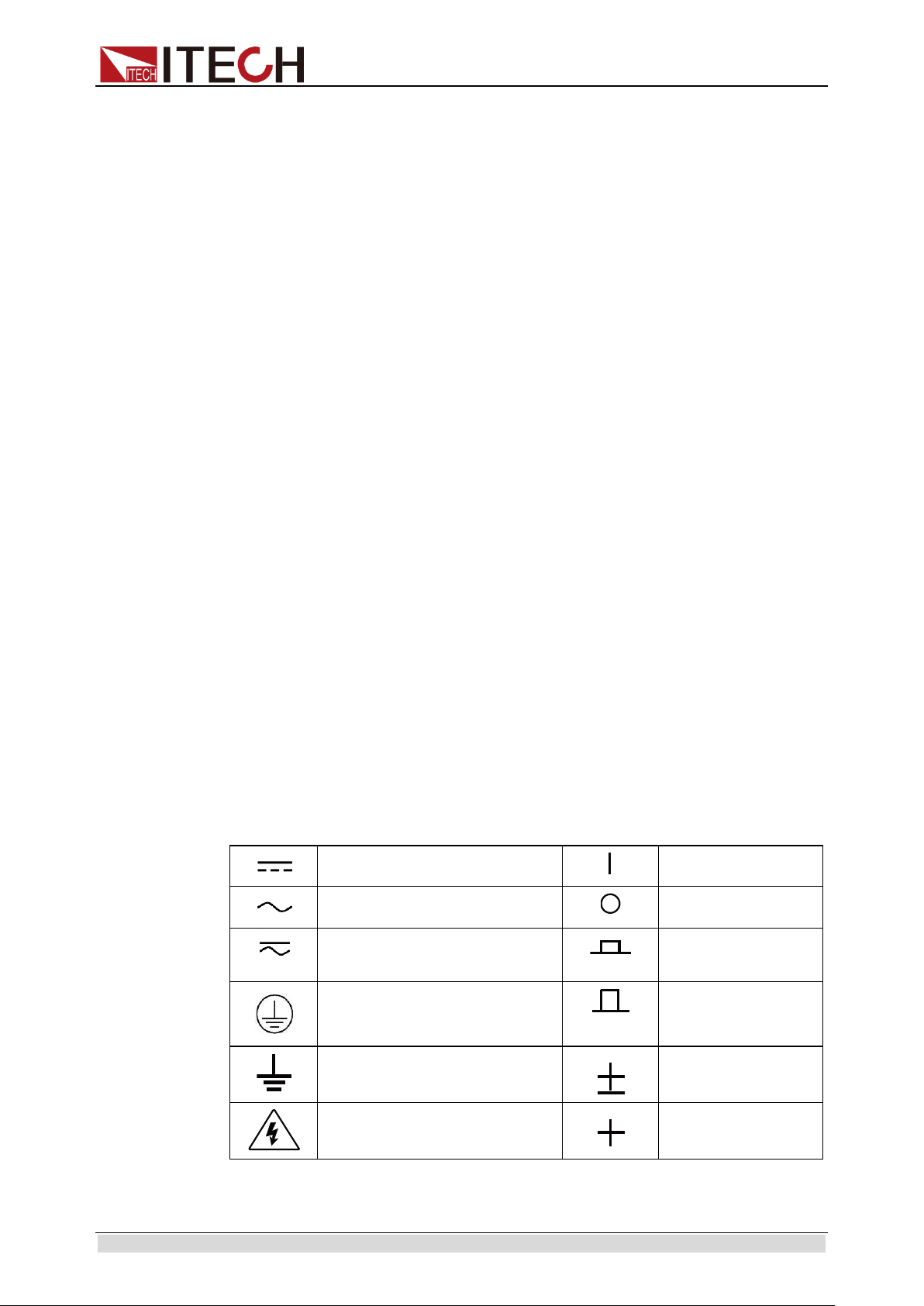
Safety Signs
Direct current
ON (power)
Alternating current
OFF (power)
Both direct and alternating
current
Power-on state
Protective earth (ground)
terminal
Power-off state
Earth (ground) terminal
Reference terminal
Caution
Positive terminal
IT7300 User’s Manual
Copyright © Itech Electronic Co., Ltd. ii
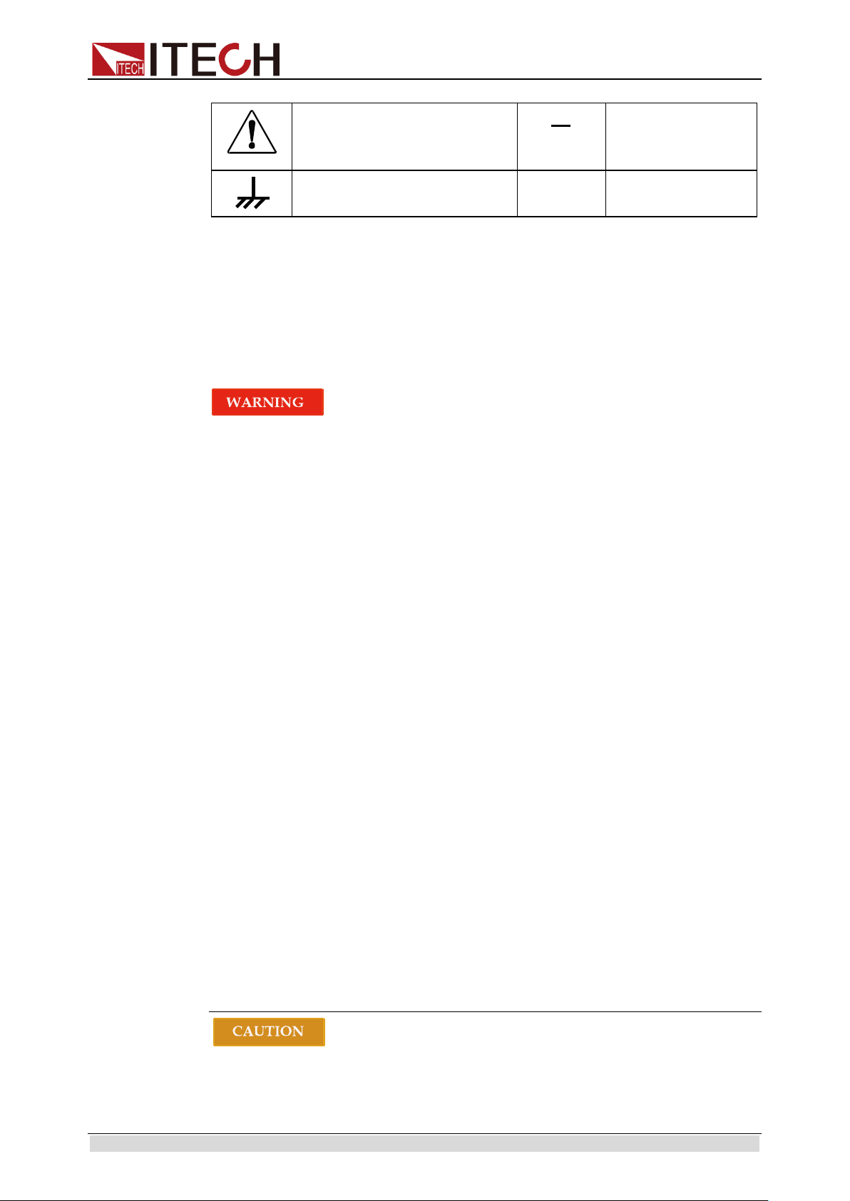
Warning (refer to this manual
for specific Warning or
Caution information)
Negative terminal
A chassis terminal
-
-
Safety Precautions
The following safety precautions must be observed during all phases of
operation of this instrument. Failure to comply with these precautions or specific
warnings elsewhere in this manual will constitute a default under safety
standards of design, manufacture and intended use of the instrument. ITECH
assumes no liability for the customer’s failure to comply with these precautions.
⚫ Do not use the instrument if it is damaged. Before operation, check
the casing to see whether it cracks. Do not operate the instrument in
the presence of inflammable gasses, vapors or dusts.
⚫ The power supply is provided with a power line during delivery and
should be connected to junction box. Before operation, be sure that
the power supply is well grounded. Make sure to use the power cord
supplied by ITECH.
⚫ Check all marks on the instrument before connecting the instrument
to power supply.
⚫ Use electric wires of appropriate load. All loading wires should be
capable of bearing maximum short-circuit of electronic load without
overheating. If there are multiple loads, each pair of the load power
cord must be carry out the full rated short-circuit output current of
the power securely.
⚫ Ensure the voltage fluctuation of mains supply is less than 10% of the
working voltage range in order to reduce risks of fire and electric
shock.
⚫ Do not install alternative parts on the instrument or perform any
unauthorized modification.
⚫ Do not use the instrument if the detachable cover is removed or
loosen.
⚫ To prevent the possibility of accidental injuries, be sure to use the
power adapter supplied by the manufacturer only.
⚫ We do not accept responsibility for any direct or indirect financial
damage or loss of profit that might occur when using the instrument.
⚫ This instrument is used for industrial purposes, do not apply this
product to IT power supply system.
⚫ Never use the instrument with a life-support system or any other
equipment subject to safety requirements.
⚫ Failure to use the instrument as directed by the manufacturer may
render its protective features void.
⚫ Always clean the casing with a dry cloth. Do not clean the internals.
IT7300 User’s Manual
Copyright © Itech Electronic Co., Ltd. iii
⚫ Make sure the vent hole is always unblocked.
Environmental Conditions
The IT7300 series power supply can only be used indoors or in low
condensation areas. The following table shows general environmental
requirements for this instrument.
Environmental conditions
Requirement
Operating temperature
0°C - 40°C
Operating humidity
20% - 80%(non condensing)
Storage temperature
-10°C - 70 ° C
Altitude
Operating up to 2,000 meters
Installation category
II
Pollution degree
Pollution degree 2
NOTE
In order to ensure the accuracy of measurement, it is recommended to operate the
instrument half an hour after start-up.
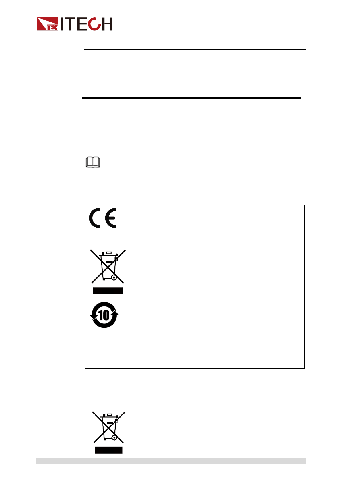
Regulation Tag
The CE tag shows that the product
complies with the provisions of all
relevant European laws (if the year is
shown, it indicates that the year when
the design is approved).
This instrument complies with the WEEE
directive (2002/96/EC) tag
requirements. This attached product tag
shows that the electrical/electronic
product cannot be discarded in
household waste.
This symbol indicates that no danger
will happen or toxic substances will not
leak or cause damage in normal use
within the specified period. The
service life of the product is 10 years.
The product can be used safely within
the environmental protection period;
otherwise, the product should be put
into the recycling system.
Waste Electrical and Electronic Equipment (WEEE)
Directive
Waste electrical and electronic equipment (WEEE) directive,
2002/96/EC
The product complies with tag requirements of the WEEE
directive (2002/96/EC). This tag indicates that the electronic
equipment cannot be disposed of as ordinary household
waste.

IT7300 User’s Manual
Copyright © Itech Electronic Co., Ltd. iv
Product Category
According to the equipment classification in Annex I of the
WEEE directive, this instrument belongs to the “Monitoring”
product.
If you want to return the unnecessary instrument, please
contact the nearest sales office of ITECH.

IT7300 User’s Manual
Copyright © Itech Electronic Co., Ltd. v
Compliance Information
Complies with the essential requirements of the following applicable European
Directives, and carries the CE marking accordingly:
⚫ Electromagnetic Compatibility (EMC) Directive 2014/30/EU
⚫ Low-Voltage Directive (Safety) 2014/35/EU
Conforms with the following product standards:
EMC Standard
IEC 61326-1:2012/ EN 61326-1:2013 ¹²³
Reference Standards
CISPR 11:2009+A1:2010/ EN 55011:2009+A1:2010 (Group 1, Class A)
IEC 61000-4-2:2008/ EN 61000-4-2:2009
IEC 61000-4-3:2006+A1:2007+A2:2010/ EN 61000-4-3:2006+A1:2008+A2:2010
IEC 61000-4-4:2004+A1:2010/ EN 61000-4-4:2004+A1:2010
IEC 61000-4-5:2005/ EN 61000-4-5:2006
IEC 61000-4-6:2008/ EN 61000-4-6:2009
IEC 61000-4-11:2004/ EN 61000-4-11:2004
1. The product is intended for use in non-residential/non-domestic environments. Use of the
product in residential/domestic environments may cause electromagnetic interference.
2. Connection of the instrument to a test object may produce radiations beyond the specified
limit.
3. Use high-performance shielded interface cable to ensure conformity with the EMC standards
listed above.
Safety Standard
IEC 61010-1:2010/ EN 61010-1:2010

IT7300 User’s Manual
Copyright © Itech Electronic Co., Ltd. vi
Content
Certification and Quality Assurance ........................................................................................................... i
Warranty Service ........................................................................................................................................ i
Limitation of Warranty ................................................................................................................................. i
Safety Signs................................................................................................................................................ i
Safety Precautions ..................................................................................................................................... ii
Environmental Conditions .......................................................................................................................... iii
Regulation Tag ........................................................................................................................................... iii
Waste Electrical and Electronic Equipment (WEEE) Directive .................................................................. iii
Compliance Information ............................................................................................................................. v
Chapter1 Acceptance and Installation ................................................................................................ 1
1.1 Confirm Package Contents.................................................................................................................. 1
1.2 Installation Position .............................................................................................................................. 1
1.3 Installation of Power Cord ................................................................................................................. 15
1.4 Connecting Test Cables (Optional) .................................................................................................... 16
Chapter2 Quick Start........................................................................................................................... 20
2.1 Brief Introduction ............................................................................................................................... 20
2.2 Introduction of Front Panel ................................................................................................................ 21
2.3 Key Introduction ................................................................................................................................. 23
2.4 VFD Indicator Description.................................................................................................................. 24
2.5 Introduction of Rear Panel ................................................................................................................. 25
2.6 Power-on Selftest .............................................................................................................................. 27
2.7 Voltage Output Checkout................................................................................................................... 29
Chapter3 Function and Features ....................................................................................................... 30
3.1 Switching of Local/Remote Operation Modes ................................................................................... 30
3.2 Voltage Setup .................................................................................................................................... 30
3.3 Frequency Setup ............................................................................................................................... 31
3.4 Phase Angle Setup ............................................................................................................................ 31
3.5 Output On/Off Operation ................................................................................................................... 31
3.6 Switch the VFD Display Items ........................................................................................................... 31
3.7 Save and Recall Operation................................................................................................................ 32
3.8 Trigger Operation ............................................................................................................................... 32
3.9 Menu Operation ................................................................................................................................. 33
3.10 Function Operation .......................................................................................................................... 37
3.11 Output Range................................................................................................................................... 44
3.12 Key Lock .......................................................................................................................................... 44
3.13 BNC ................................................................................................................................................. 45
3.14 3ø-Setup .......................................................................................................................................... 46
Chapter4 Specification ....................................................................................................................... 49
4.1 Specification ...................................................................................................................................... 49
4.2 Supplemental Characteristics ............................................................................................................ 69
Chapter5 Remote Control ................................................................................................................... 70
5.1 RS232 Interface ................................................................................................................................. 70
5.2 USB Interface .................................................................................................................................... 71
5.3 LAN Interface ..................................................................................................................................... 72
5.4 GPIB Interface ................................................................................................................................... 72
Appendix .................................................................................................................................................... 73
Specifications of Red and Black Test Lines ............................................................................................. 73
Acceptance and Installation
Copyright © Itech Electronic Co., Ltd. 1
Chapter1 Acceptance and Installation
Power supply is a high level safety equipment, there is a protected ground
terminal. Before Installation or operation, please read the safety signs and
instructions in this manual.
1.1 Confirm Package Contents
Open the package and check the articles within package box before operation.
In case of any non-conformity, missing or appearance wearing, please contact
ITECH immediately.
The package box should comprise:
Device name
Quantity
Model
Remarks
Programmable
AC Power
Supply
x1
IT7300
series
IT7300 series include:
IT7321/IT7322/IT7322H/IT7324/
IT7324H/IT7326/IT7326H/IT7322T/
IT7322HT/IT7324T/IT7324HT/IT73
26T/IT7326HT
Power Cord
x1
-
Different types of instruments are
equipped with different power
cables. For detailed specifications,
refer to 1.3 Installation of power
cord.
USB cable
x1
-
-
CD
x1
-
Comprising user manual and
documents related to programming
and grammatical guidelines.
Factory
alignment
report
x1
-
Test report before delivery
NOTE
After confirming that package contents are consistent and correct, please appropriately
keep package box and related contents. The package requirements should be met when
the instrument is returned to factory for repair.
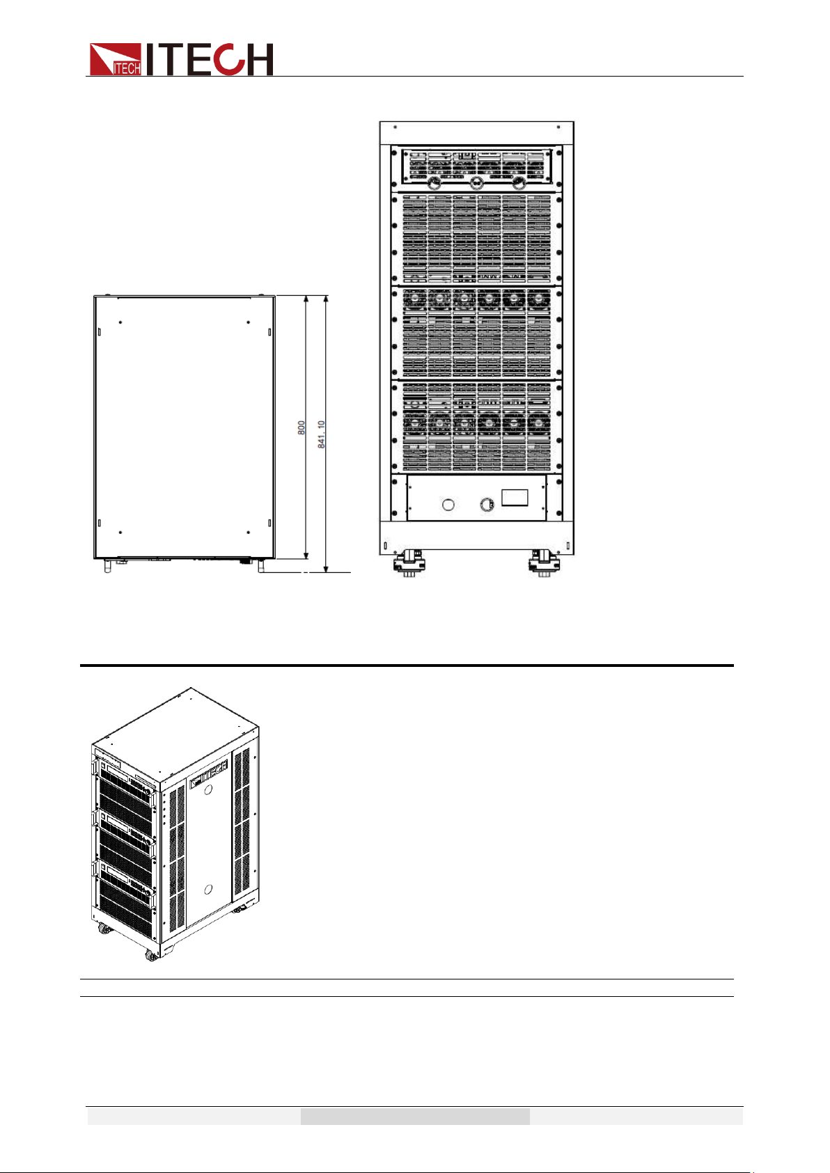
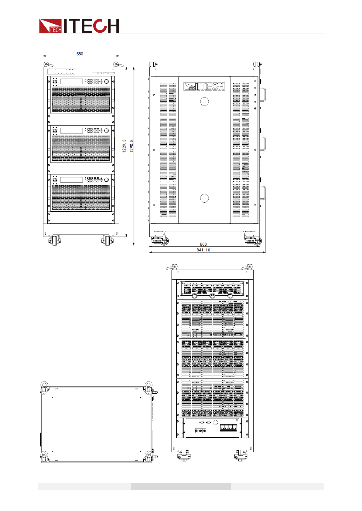
1.2 Installation Position
The instrument should be installed at well-ventilated and rational-sized space.
Please select appropriate space for installation based on the power supply size
Acceptance and Installation
Copyright © Itech Electronic Co., Ltd. 2
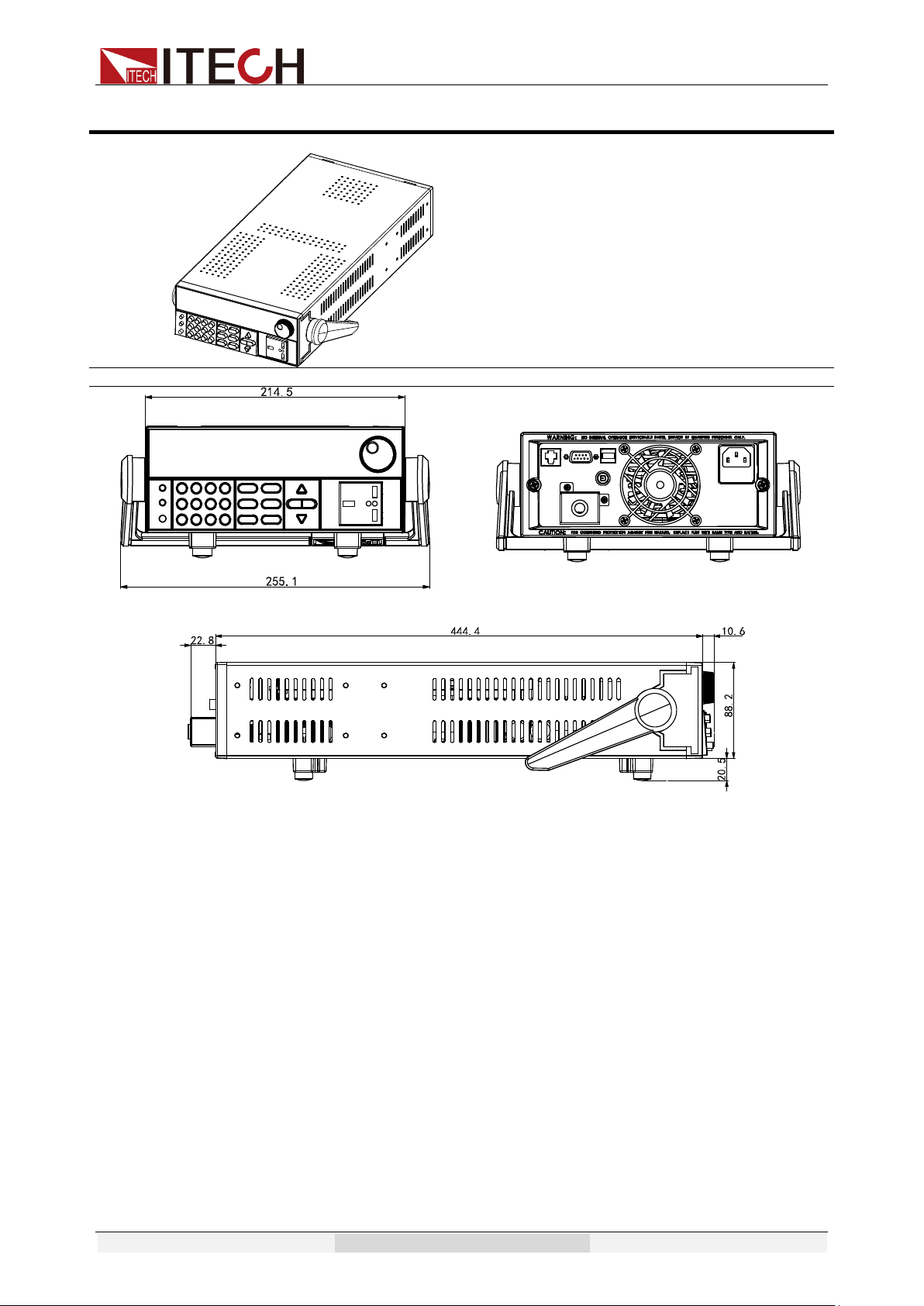
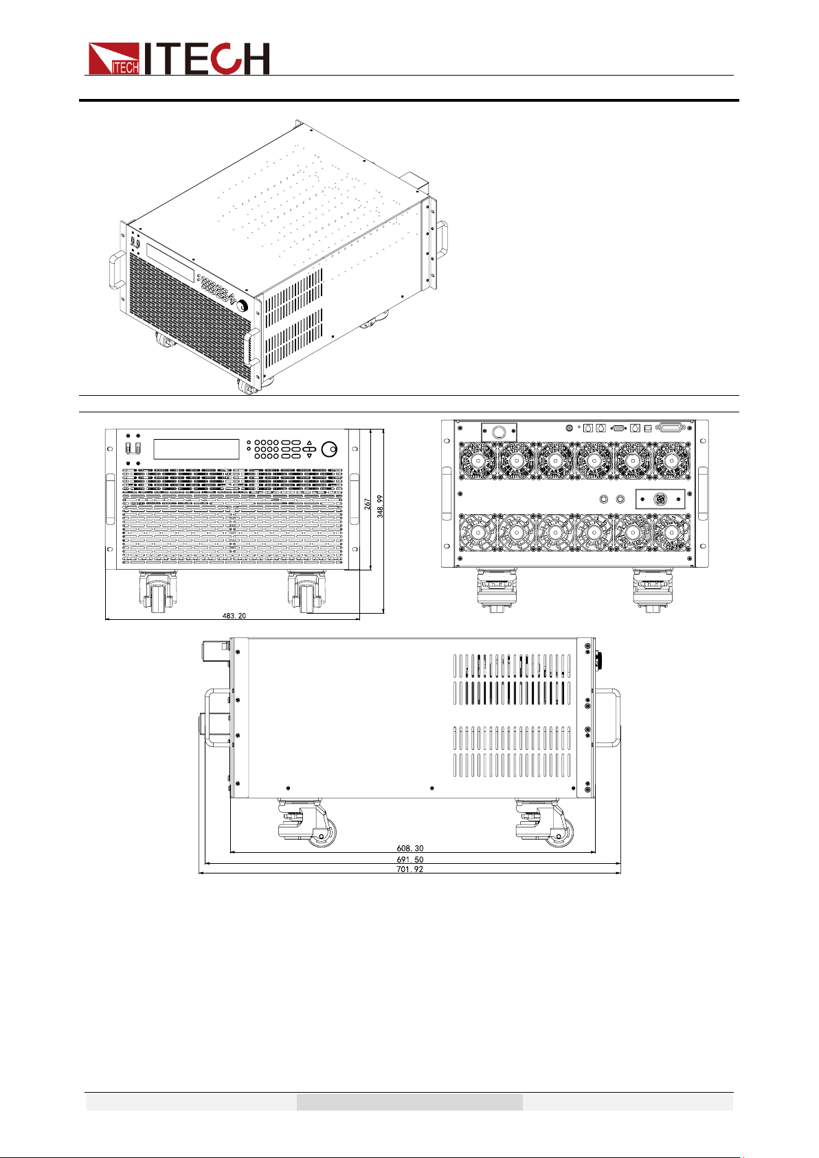
Model IT7321
Detailed dimensional drawings
Acceptance and Installation
Copyright © Itech Electronic Co., Ltd. 3
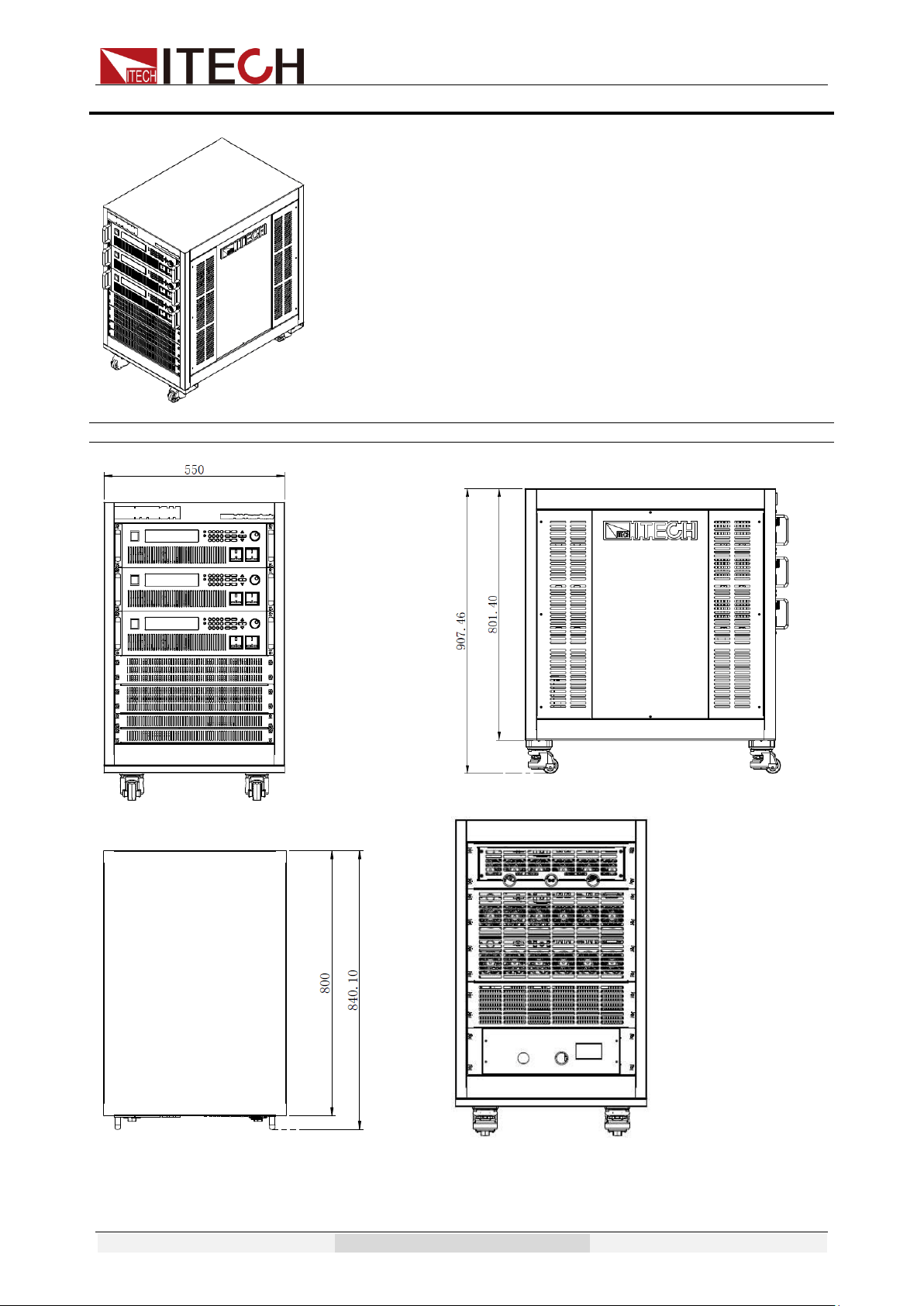
Model IT7322/IT7324
Detailed dimensional drawings
Acceptance and Installation
Copyright © Itech Electronic Co., Ltd. 4
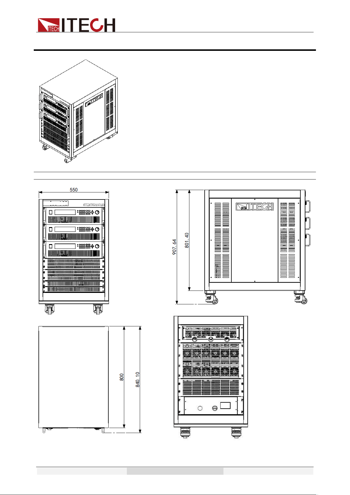
Model IT7322H/IT7324H
Detailed dimensional drawings
Acceptance and Installation
Copyright © Itech Electronic Co., Ltd. 5
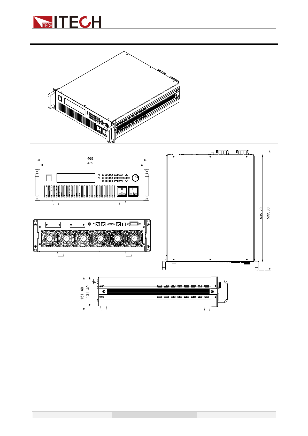
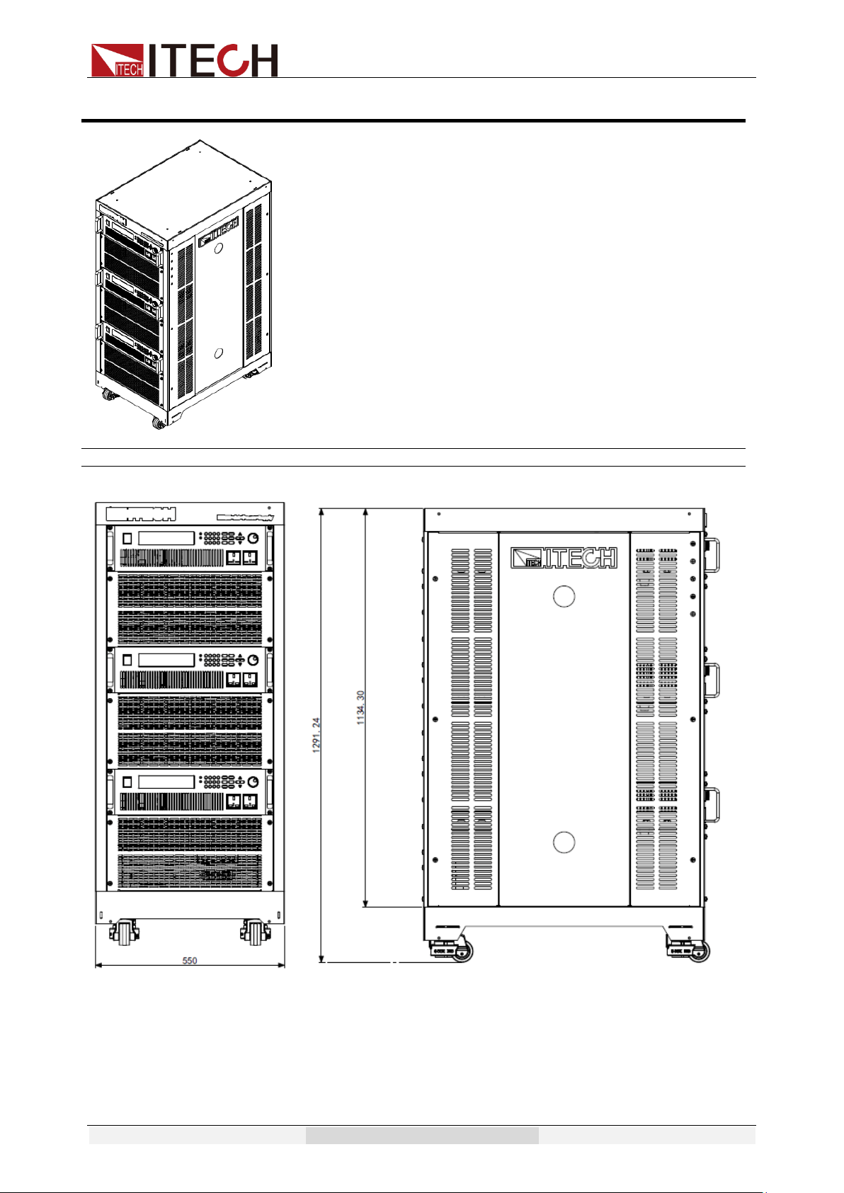
Model IT7326
Detailed dimensional drawings
Acceptance and Installation
Copyright © Itech Electronic Co., Ltd. 6
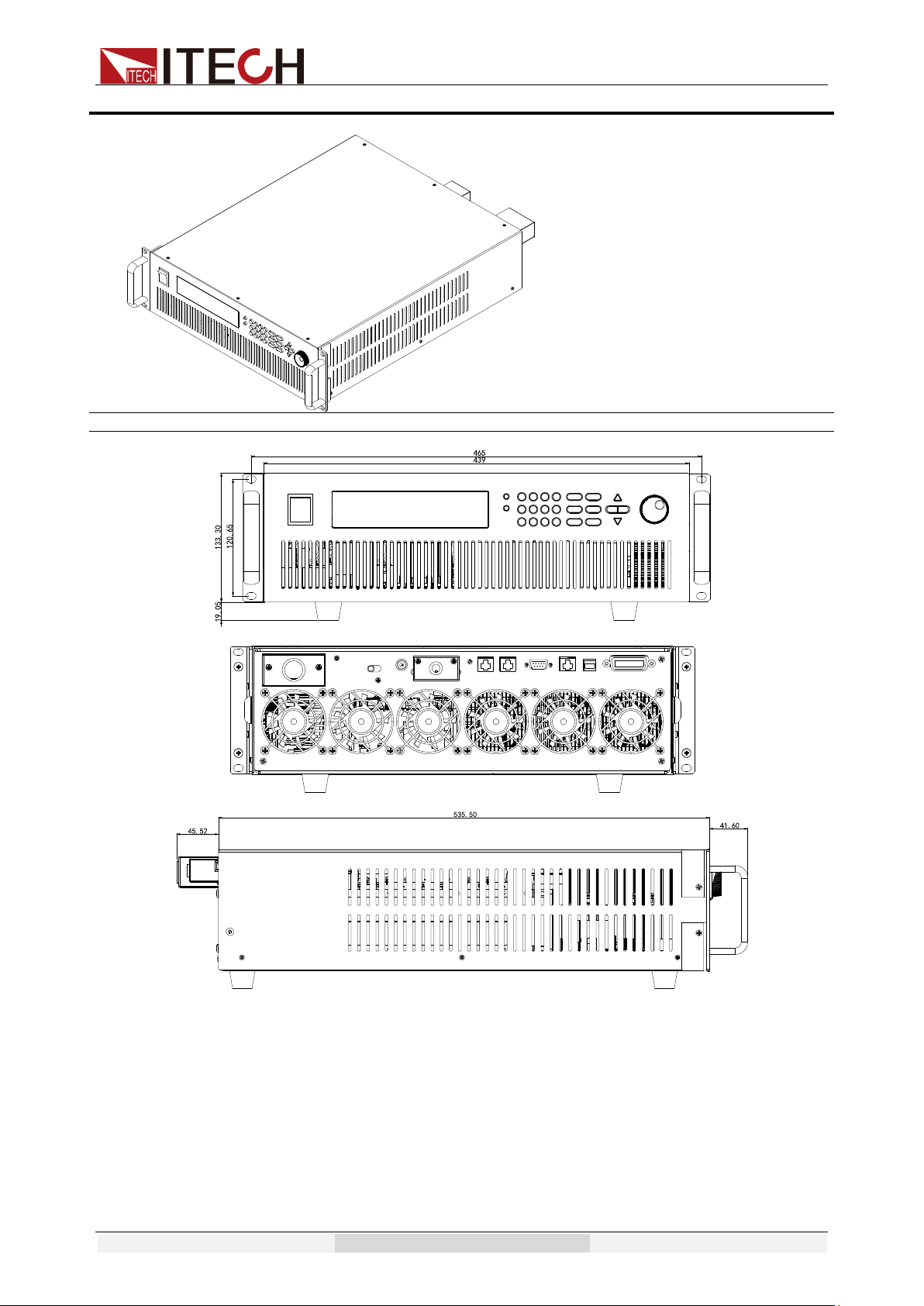
Model IT7326H
Detailed dimensional drawings
Acceptance and Installation
Copyright © Itech Electronic Co., Ltd. 7
Model IT7322T
Detailed dimensional drawings
Acceptance and Installation
Copyright © Itech Electronic Co., Ltd. 8
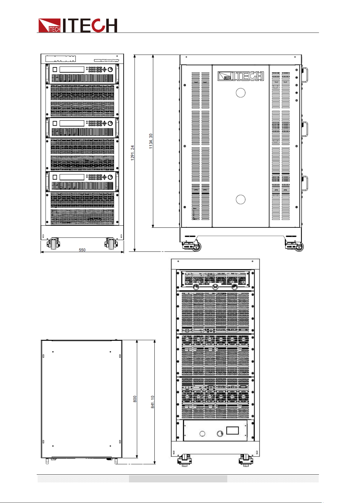
Model IT7322HT
Detailed dimensional drawings
Acceptance and Installation
Copyright © Itech Electronic Co., Ltd. 9
Model IT7324T
Detailed dimensional drawings
Acceptance and Installation
Copyright © Itech Electronic Co., Ltd. 10
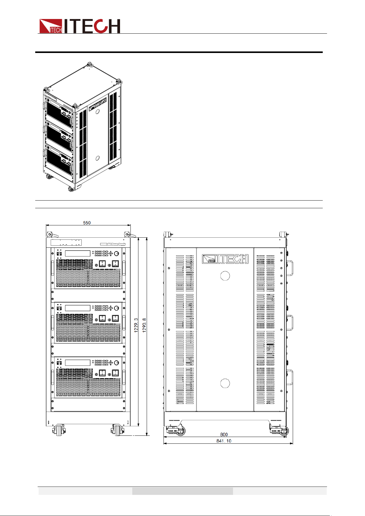
Model IT7324HT
Detailed dimensional drawings
Acceptance and Installation
Copyright © Itech Electronic Co., Ltd. 11
Acceptance and Installation
Copyright © Itech Electronic Co., Ltd. 12
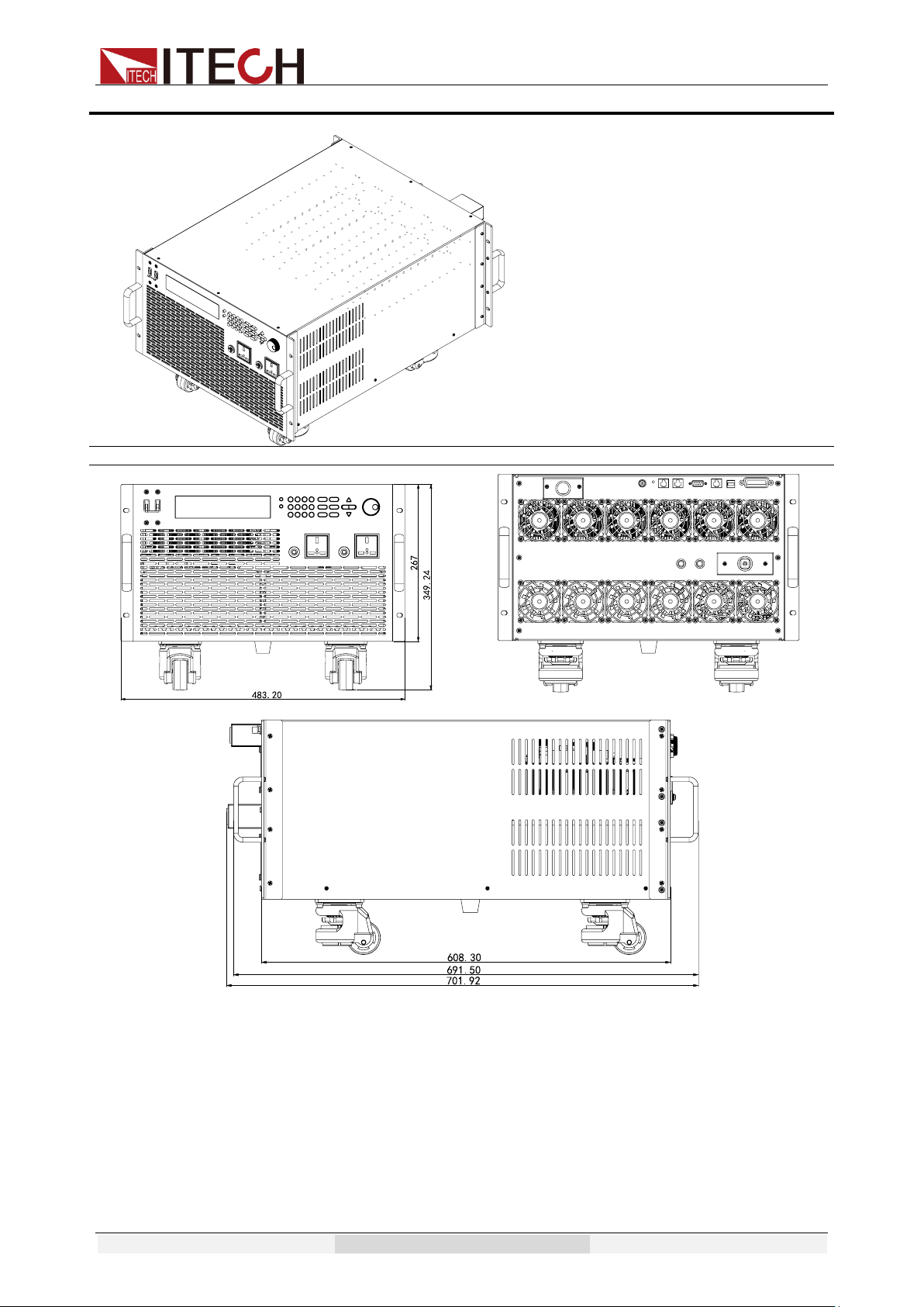
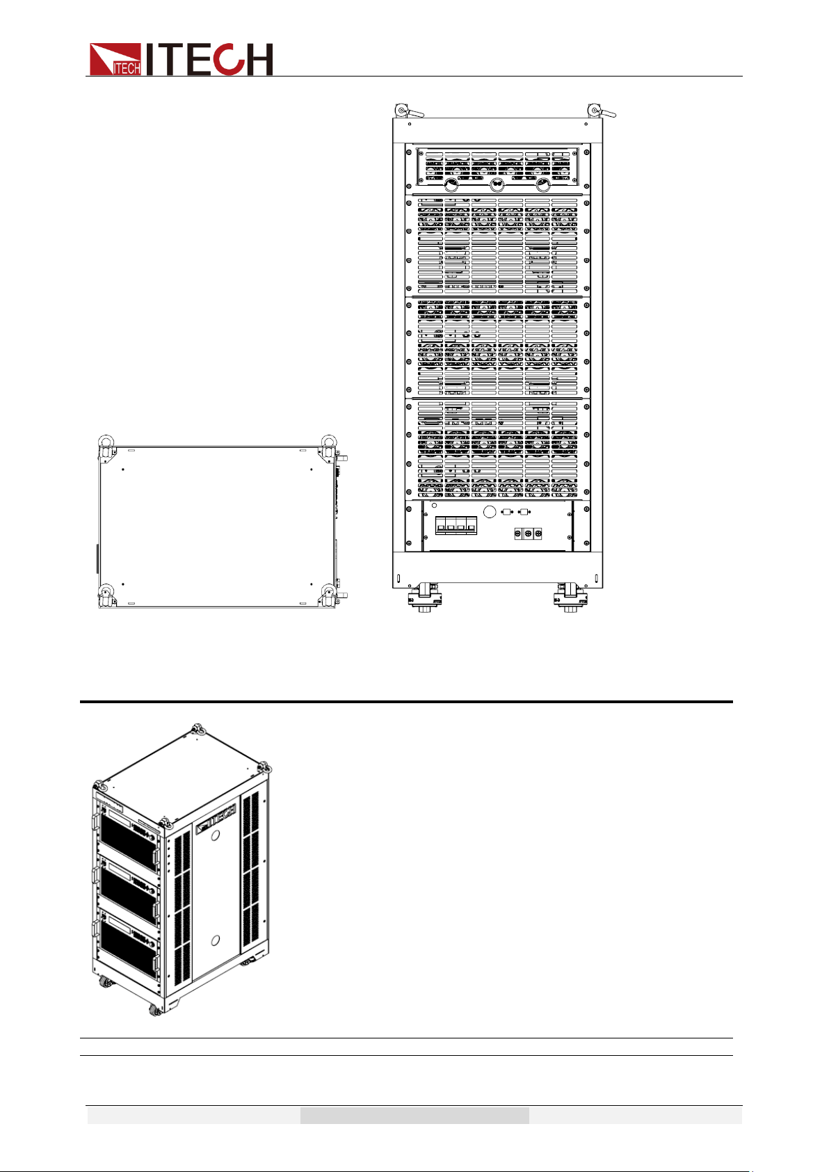
Model IT7326T
Detailed dimensional drawings
Acceptance and Installation
Copyright © Itech Electronic Co., Ltd. 13
Model IT7326HT
Detailed dimensional drawings
Acceptance and Installation
Copyright © Itech Electronic Co., Ltd. 14
Acceptance and Installation
Copyright © Itech Electronic Co., Ltd. 15
1.3 Installation of Power Cord
Connect power cord of standard accessories and ensure that the power supply
is under normal power supply.
AC power input level
Working voltage for IT7300 series power supply is shown as follows. So please
pay attention to the working input voltage.
⚫ IT7321, IT7322, IT7322H, IT7324, and IT7324H models support
110V/220V AC input.
The AC line switch of IT7321 is located at the bottom of the unit.
The AC line switches of IT7322, IT7322H, IT7324, and IT7324H are
located at the rear of the unit. Please pay attention to the AC level setup
before provide AC power.
AC power input level:
- Option 01:220VAC ± 10%, 47 to 63 Hz
- Option 02: 110VAC ± 10%, 47 to 63 Hz
⚫ IT7326 and IT7326H models support 220V AC input.
⚫ IT7322T, IT7322HT, IT7324T, IT7324HT, IT7326T and IT7326HT models
support 380V AC input.
Connecting AC Input
The power cords supplied with this product is certified for safety. In case
the supplied lines assembly needs to be replaced, or an extension lines
must be added, be sure that it can meet the required power ratings of this
product. Any misuse voids the warranty of this product.
Before connecting power cords, turn off the power.
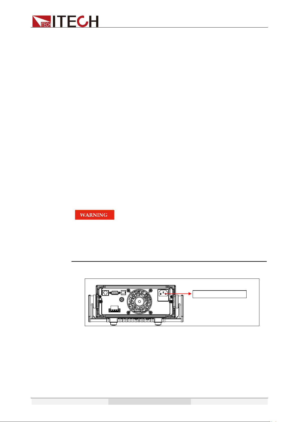
⚫ IT7321: Connect standard power cord to the power supply input terminal.
⚫ IT7322/IT7322H/IT7324/IT7324H/IT7326/IT7326H AC input connector as
follows. (Take the example of IT7324H.)
Connecting AC Input
Acceptance and Installation
Copyright © Itech Electronic Co., Ltd. 16
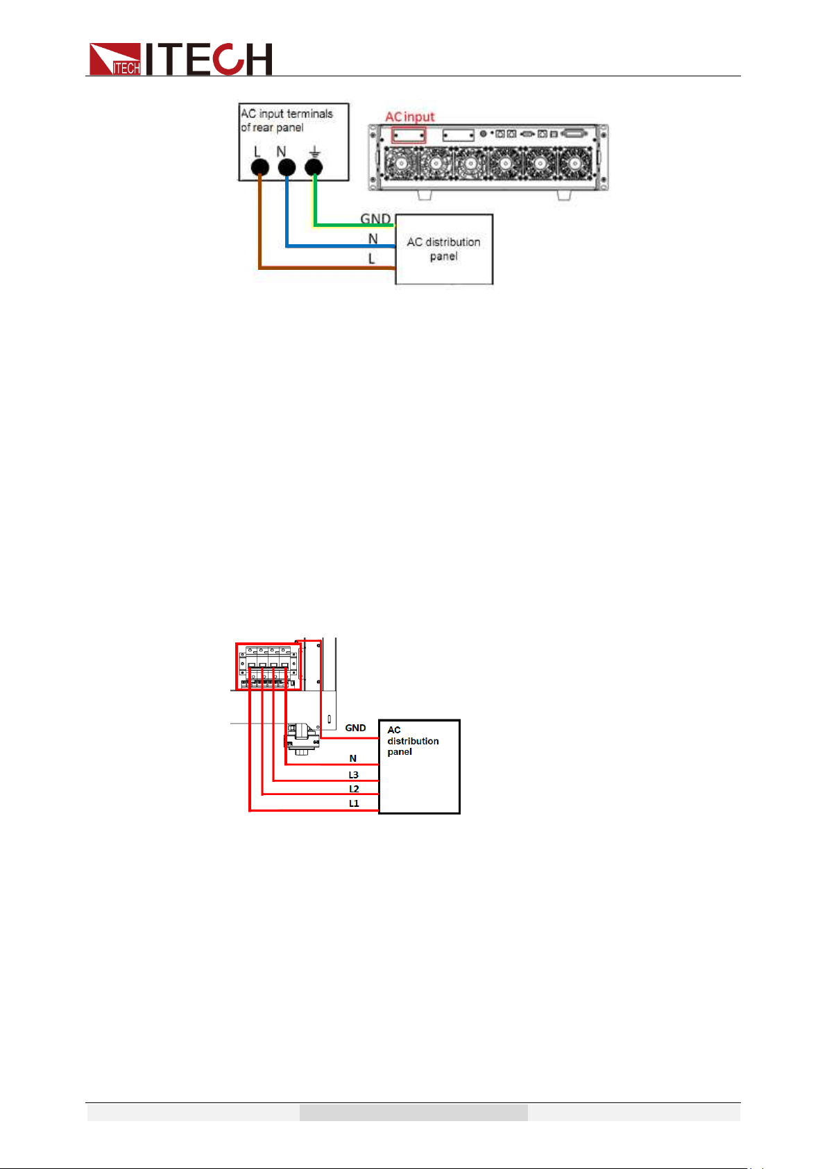
1. In the above illustration, one end of the AC power cord is connected to
the AC input terminal in the rear panel of the power supply.
Connect the wire, zero line and ground to the corresponding terminal of
the device. Before inserting, please loose the screw, lock the screw
when it is inserted.
2. Connect the three terminals brown to line (L), blue to neutral (N), and
yellow-green to ground (GND) on the other end of the power cord to
your AC distribution panel.
⚫ IT7322T/IT7322HT/IT7324T/IT7324HT/IT7326T/IT7326HT AC input
connections are the same, and the end of the AC power cord connected to
the AC input terminal on the rear panel of the power supply is connected.
The user only needs to connect the other end of the AC power cord to the
AC distribution panel, the brown terminal is connected to L1, the gray
terminal is connected to L2, the black terminal is connected to L3, the blue
terminal is connected to N, and the yellow terminal is connected to the
GND.
The connection diagram is as follows:
1.4 Connecting Test Cables (Optional)
Test cables are not standard accessories of the instrument. Please select
optional red and black test cables for individual sales based on the maximum
current value. For specifications of test cables and maximum current values,
refer to “Specifications of Red and Black Test Lines” in “Appendix”.

Acceptance and Installation
Copyright © Itech Electronic Co., Ltd. 17
⚫ Before connecting test cables, be sure to switch off the instrument.
Power switch is in Off position. Otherwise, contact with output
terminals in rear panel may cause electrical shock.
⚫ To avoid electrical shock, before testing, please make sure the rating
values of the testing cables, and do not measure the current that
higher than the rating value. All test cables shall be capable of
withstanding the maximum short circuit output current of the power
supply without causing overheat.
⚫ If several loads are provided, each pair of load wires shall safely
withstand the rated short circuit output current of the power supply
under full load.
⚫ Always use test cables provided by ITECH to connect the equipment.
If test cables from other factories are used, please check that the test
cable can withstand maximum current.
The front panel of IT7300 series power supply is equipped with the front panel
output terminal and rear panel output terminal (see 2.2 Introduction of front
panel and 2.5 Introduction of rear panel).
Before using the output terminal of the rear panel to connect the device under
test (DUT), remove the protective cover or panel covering the output terminal
on the rear panel firstly, then connect the test cables, and take the other end of
the test cables out of the hole in the protective cover or panel, and then put the
protective cover or panel back in place. To avoid the risk of electric shock if the
output terminal is accidentally touched during the test operation.
Connection of the front panel output terminal
The models that support the front panel output are: IT7321, IT7322, IT7324,
IT7326, IT7322T, IT7324T, and IT7326T.
The connection method of the front panel output is as follows: directly insert the
plug at one end of the cable into the output interface of the front panel, and
connect the other end to the DUT.
The maximum output current of the front panel output terminal is 10A. In order
to facilitate operation, the user can directly connect the front panel output
terminal if the output current is less than 10A.
If the output current of the output terminal of power supply exceeds 10A, the
user must connect the rear panel output terminal. If you want to obtain the
specifications of the equipment, please refer to 4.1 Specification.
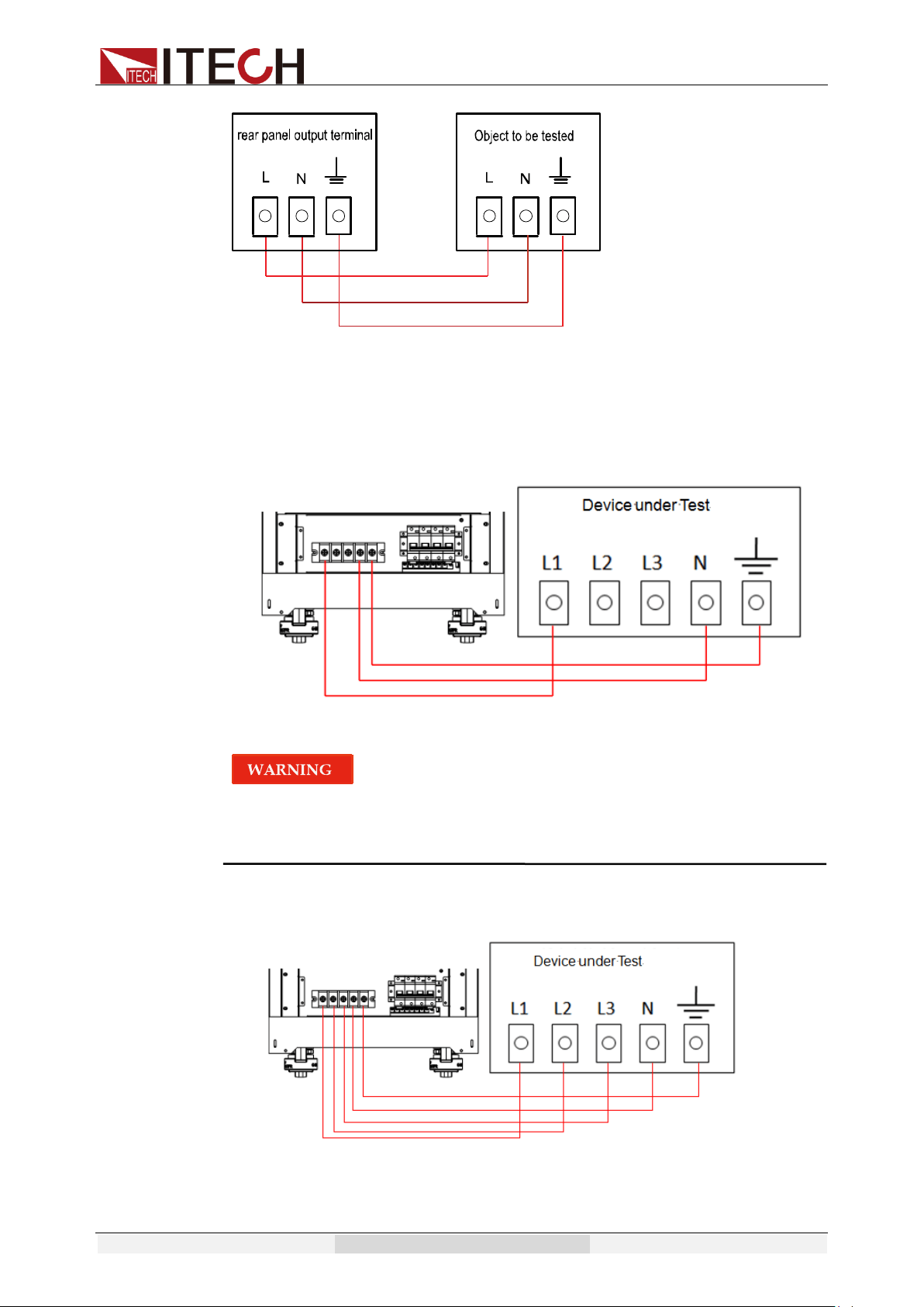
Connection of the rear panel output terminal
The user can connect the rear panel output terminal according to the power
output specifications. Specific connection of
IT7321/IT7322/IT7322H/IT7324/IT7324H/IT7326/IT7326H (after removing the
protective cover) is shown in the figure below.
Acceptance and Installation
Copyright © Itech Electronic Co., Ltd. 18
Specific connection of
IT7322T/IT7322HT/IT7324T/IT7324HT/IT7326T/IT7326HT (after removing the
panel) is shown in the figure below.
⚫ When used as a single-phase power source, the connection is shown in
the next figure.
When IT7322T/IT7322HT/IT7324T/IT7324HT/IT7326T/IT7326HT is
used as a single-phase power source, please connect the output
terminals: L1, N, GND.
⚫ When used as a three-phase power source, the connection is shown in the
next figure.
The specific steps for connecting the rear panel output terminals are as follows:

Acceptance and Installation
Copyright © Itech Electronic Co., Ltd. 19
1. Make sure the power switch of the instrument is off.
2. Remove the protective cover or panel that covers the rear panel output
terminals.
3. Unscrew the screws of the output terminals and connect the red and black
test cables to the output terminals. Re-tighten the screws.
When maximum current that one test cable can withstand fails to meet the
current rated current, use several pieces of red and black test cables. For
example, the maximum current is 1,200A, then 4 pieces of 360A red and
black cables are required.
4. Take the other end of the test cables out of the hole in the protective cover
or panel and install the cover or panel back.
5. Connect the other end of the red and black cables to the DUT terminal.

Quick start
Copyright © Itech Electronic Co., Ltd. 20
Chapter2 Quick Start
This chapter introduces the front panel, the rear panel, key functions and VFD
display function of the power supply, make sure that you can quickly know the
appearance, instruction and the key function before you operate the power
supply. Help you make better use of this series of power supply.
2.1 Brief Introduction
IT7300 series of power supply is divided into the single-phase
(IT7321/IT7322/IT7322H/IT7324/IT7324H/IT7326/IT7326H) and three-phase
(IT7322T/IT7322HT/IT7324T/IT7324HT/IT7326T/IT7326HT) programmable AC
power supply. The three-phase power supply is assembled by three
corresponding single-phase power supplies. For example, IT7322T is
assembled by IT7322. Therefore, the introduction to front panel, key, VFD
indicator, rear panel, power-on selftest, voltage output checkout, and function
and features of three-phase power supply are similar to those of single-phase
power supply.
IT7300 series can analog various AC inputs, and measure a series of important
parameters of DUT. IT7300 series power supply has following standard
communication interfaces: LAN, USB, GPIB (except IT7321) and RS232. With
combined features of both desktop and systematic power supplies, it can
deliver multi-purpose solutions based on design and test requirements. Main
features and advantages are listed below:
⚫ Vacuum fluorescent display (VFD)
⚫ LED display of panel function keys
⚫ Adjustable set values by knob
⚫ Output is switch control
⚫ Display Vrms, Irms, Ipeak, frequency, PF, apparent power and active
power simultaneously
⚫ Programmable frequency:45HZ-500HZ
⚫ Turn on, turn off phase angle control (0-360°)
⚫ Analog surge/trapped wave
⚫ Support front and rear panel output
⚫ High accuracy and resolution
⚫ Memory capacity:10 groups
⚫ Over-voltage, over-power, over-current, over-temperature protection
features
⚫ Smart temperature-control fan with low noise
⚫ Standard communication interface LAN, USB, GPIB (except IT7321),
RS232
⚫ Software monitoring via computer
⚫ Support 3-phase AC power supply function when 3 units are
connected together via System Bus (except IT7321)
Model
Voltage
Current
Power
IT7321
300V
3A
300VA
IT7322
300V
6A
750VA
IT7322H
500V
3A
750VA
Quick start
Copyright © Itech Electronic Co., Ltd. 21
IT7324
300V
12A
1500VA
IT7324H
500V
6A
1500VA
IT7326
300V
24A
3000VA
IT7326H
500V
12A
3000VA
IT7322T
300V
6A
2250VA
IT7322HT
500V
3A
2250VA
IT7324T
300V
12A
4500VA
IT7324HT
500V
6A
4500VA
IT7326T
300V
24A
9000VA
IT7326HT
500V
12A
9000VA
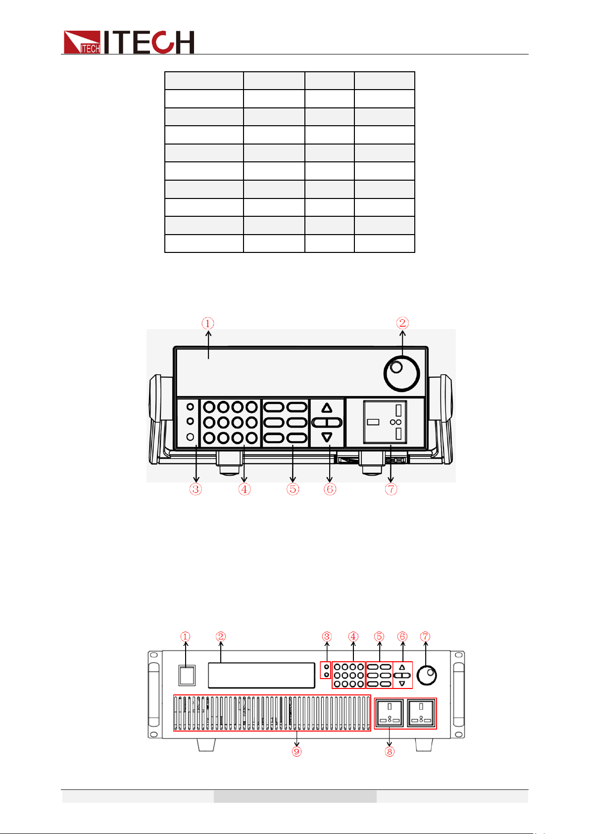
2.2 Introduction of Front Panel
⚫ Front panel of IT7321
1. VFD display
2. Rotary knob
3. Compound key, the local switch key and power switch
4. Numeric keys and ESC
5. Function keys
6. UP, DOWN, LEFT and RIGHT key
7. Output terminals
⚫ Front panel of IT7322/IT7324
1. Power button
Quick start
Copyright © Itech Electronic Co., Ltd. 22
2. VFD display
3. Compound key, the local switch key and power switch
4. Numeric keys and ESC
5. Function keys
6. UP, DOWN, LEFT and RIGHT key
7. Rotary knob
8. Output terminals
9. Fan
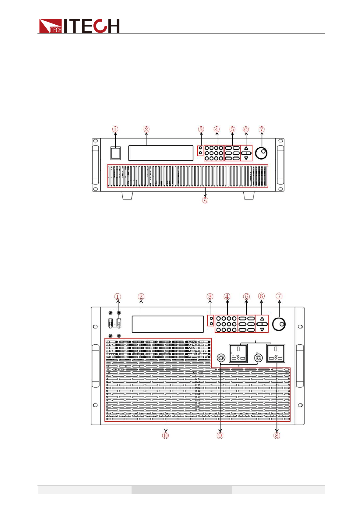
⚫ Front panel of IT7322H/IT7324H
1. Power button
2. VFD display
3. Compound key, the local switch key and power switch
4. Numeric keys and ESC
5. Function keys
6. UP, DOWN, LEFT and RIGHT key
7. Rotary knob
8. Fan
⚫ Front panel of IT7326
1. Power button
2. VFD display
3. Compound key, the local switch key and power switch
4. Numeric keys and ESC
Quick start
Copyright © Itech Electronic Co., Ltd. 23
5. Function keys
6. UP, DOWN, LEFT and RIGHT key
7. Rotary knob
8. Output terminals
9. Fuses
10. Fan
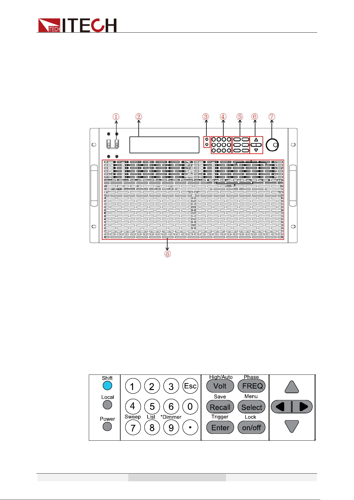
⚫ Front panel of IT7326H
1. Power button
2. VFD display
3. Compound key, the local switch key and power switch
4. Numeric keys and ESC
5. Function keys
6. UP, DOWN, LEFT and RIGHT key
7. Rotary knob
8. Fan
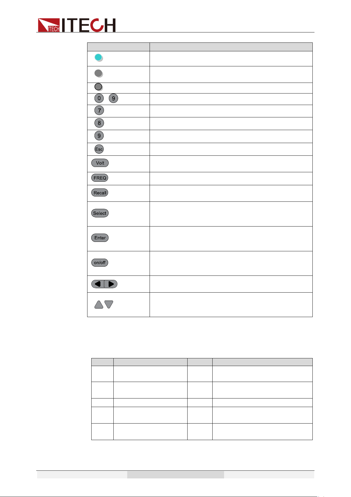
2.3 Key Introduction
Key description, see the table below:
Quick start
Copyright © Itech Electronic Co., Ltd. 24
Keys
Name and the function
(Shift)
Compound key, co-work with High/Auto, Phase, Save,
Menu, Trigger, Lock, Sweep, List and*Dimmer.
(Local)
Local button, switch from remote mode to local
operation mode
(Power)
Power on key
~
Numeric keys
/Sweep
Number 7/Sweep function key
/List
Number 8/List function key
/*Dimmer
Number 9/Dimmer function key
Cancel /return keys
/High/Auto
Set the voltage value/Switch the voltage range
between high range and Auto range mode
/Phase
Set the frequency /set the phase angle
/Save
Recall the setup from internal memory/ Store the
AC source settings in non-volatile memory.
/Menu
Switch the VFD display to be apparent power,
peak current, active power and power factor/entry
the menu setup
/Trigger
Enter key, to confirm the number entered and
operation/trigger button, which is used to trigger
the List test
/Lock
Output on (off) keys, control power output state /
keypad lock function keys, used to lock the panel
buttons
Left and right direction keys, used to set the value,
to adjust the cursor to the specified location
Up and down keys, used to turn over the item in
the menu or increase (decrease) the output
voltage or current values
2.4 VFD Indicator Description
VFD indicator function description as follow:
Char
Function description
Char
Function description
OFF
Output is off
Prot
OCP/OVP/OTP/OPP Protection
Rmt
The AC source is in
remote mode
Auto
Auto change the voltage
range
SRQ
Service request
*
Dimmer function is enabled
Error
The power supply
has an error
Shift
Shift button is pressed
Trig
Awaiting for a trigger
signal
Lock
Key operation is locked
Quick start
Copyright © Itech Electronic Co., Ltd. 25
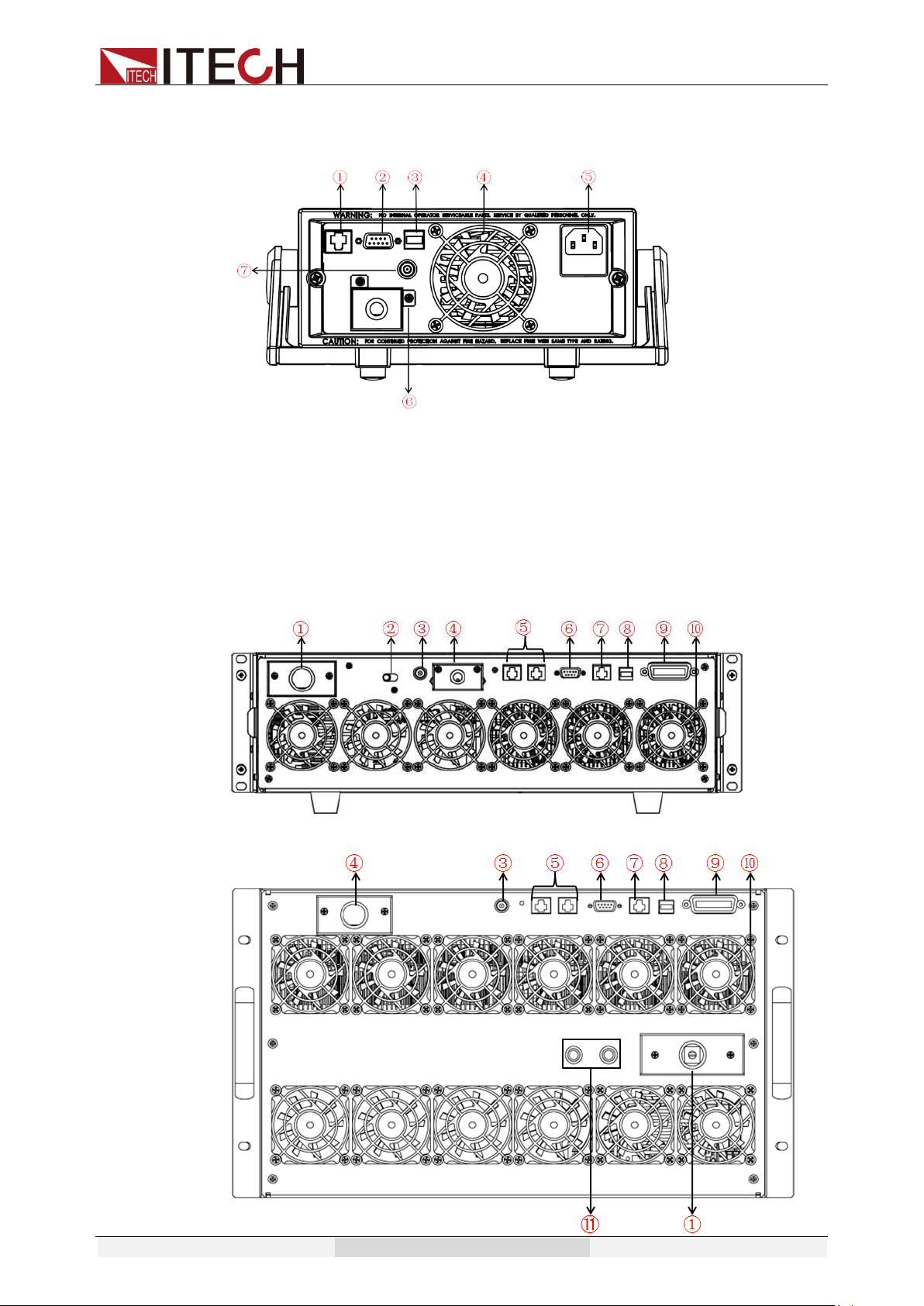
2.5 Introduction of Rear Panel
⚫ Rear panel of IT7321
1. LAN communication interface
2. RS232 communication interface
3. USB communication interface
4. Cooling fans
5. AC power socket and Fuse
6. Output terminals
7. BNC terminal
⚫ Rear panel of IT7322/IT7322H/IT7324/IT7324H
⚫ Rear panel of IT7326/IT7326H
Quick start
Copyright © Itech Electronic Co., Ltd. 26
1. AC power input socket
2. 110V/220V AC power selection switch
3. BNC terminal
4. Output terminals
5. System Bus
6. RS232 communication interface
7. LAN communication interface
8. USB communication interface
9. GPIB communication interface
10. Cooling fans
11. Fuses
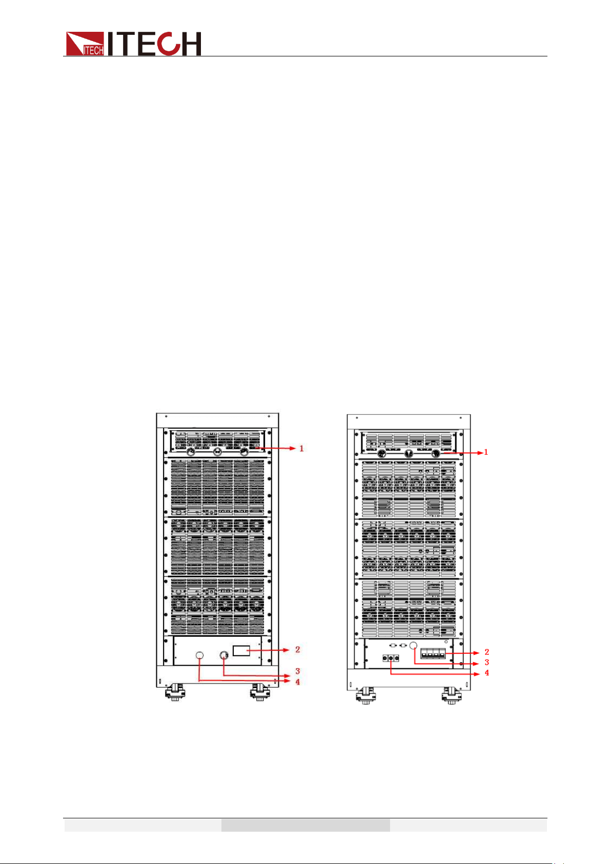
The IT7322T, IT7322HT, IT7324T, IT7324HT, IT7326T, and IT7326HT are
three-phase models that are composed of three single-phase power supplies.
The AC power input terminals and output terminals are located below the rear
panel of the cabinet. See the following illustration for details. For other terminals
(such as communication interface terminals), you need to remove the rear
panel of the corresponding position of the A-phase power supply, and then
connect the terminals.
The IT7322T, IT7322HT, IT7324T, and IT7324HT rear panels have the same
structure, so the IT7324HT is used as an example.
IT7324HT rear panel IT7326HT rear panel
1. The rear panel of the corresponding position of the A-phase power supply.
Before using the rear panel terminal function, remove the panel and then connect
the terminals.
Quick start
Copyright © Itech Electronic Co., Ltd. 27
The rear panel of the A-phase power supply (IT7322, IT7322H,
IT7324, and IT7324H) of IT7322T, IT7322HT, IT7324T, and IT7324HT
contains a 110V/220V switch. Do not move the transfer switch here,
and keep it at 220V.
2. The main power switch of the cabinet.
3. The outlet hole of the AC power input cord.
4. The outlet hole of the AC power output cord (i.e., the test cables).
2.6 Power-on Selftest
A successful selftest indicates that the purchased power product meets delivery
standards and is available for normal usage.
Before operation, please confirm that you have fully understood the safety
instructions.
⚫ To avoid burning out, be sure to confirm that power voltage matches with
supply voltage.
⚫ Be sure to connect the main power socket to the power outlet of protective
grounding. Do not use terminal board without protective grounding. Before
operation, be sure that the power supply is well grounded.
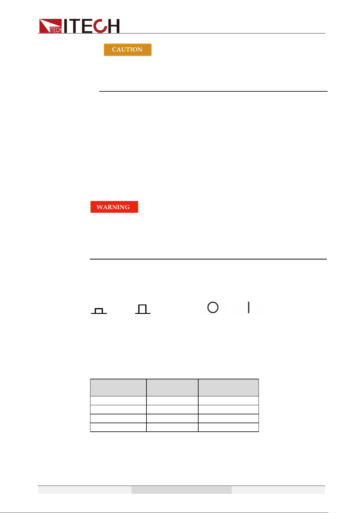
Power Switch Introduction
The switch status of single-phase power supply is as follows.
The three-phase power supplies are equipped with separate power switches,
such as master switch and branch switch. The relationship of state of all
equipment and switch states is as follow.
Master switch
state
Branch
switch state
State of all
equipment
ON
ON
ON
ON
OFF
OFF
OFF
ON
OFF
OFF
OFF
OFF
Selftest steps
Normal selftest procedures:
1. Correctly connect the power cord. Press Power key to start up.
ON OFF
OFF ON
Quick start
Copyright © Itech Electronic Co., Ltd. 28
With regards to IT7322T, IT7322HT, IT7324T, IT7324HT, IT7326T and
IT7326HT, you need to turn on three single instruments.
The power supply starts to selftest.
2. After selftest, VFD display the status as below:
During self-test of the power supply, if EEPROM has error, the “Error” indicator
on the status bar lights up. You can check the selftest error on the INFOR item
in the MENU.
Exception handling
If the power supply cannot start normally, please check and take measures by
reference to steps below.
1. Check whether the power cord is correctly connected and confirm whether
the power supply is powered.
Correct wiring of power cord => 2
Incorrect wiring of power cord => Re-connect the power cord and check
whether the exception is removed.
2. Check whether the power in On. Power key is under “ ” On status.
Yes => 3
No => Please check the Power key to start power and check whether the
exception is removed.
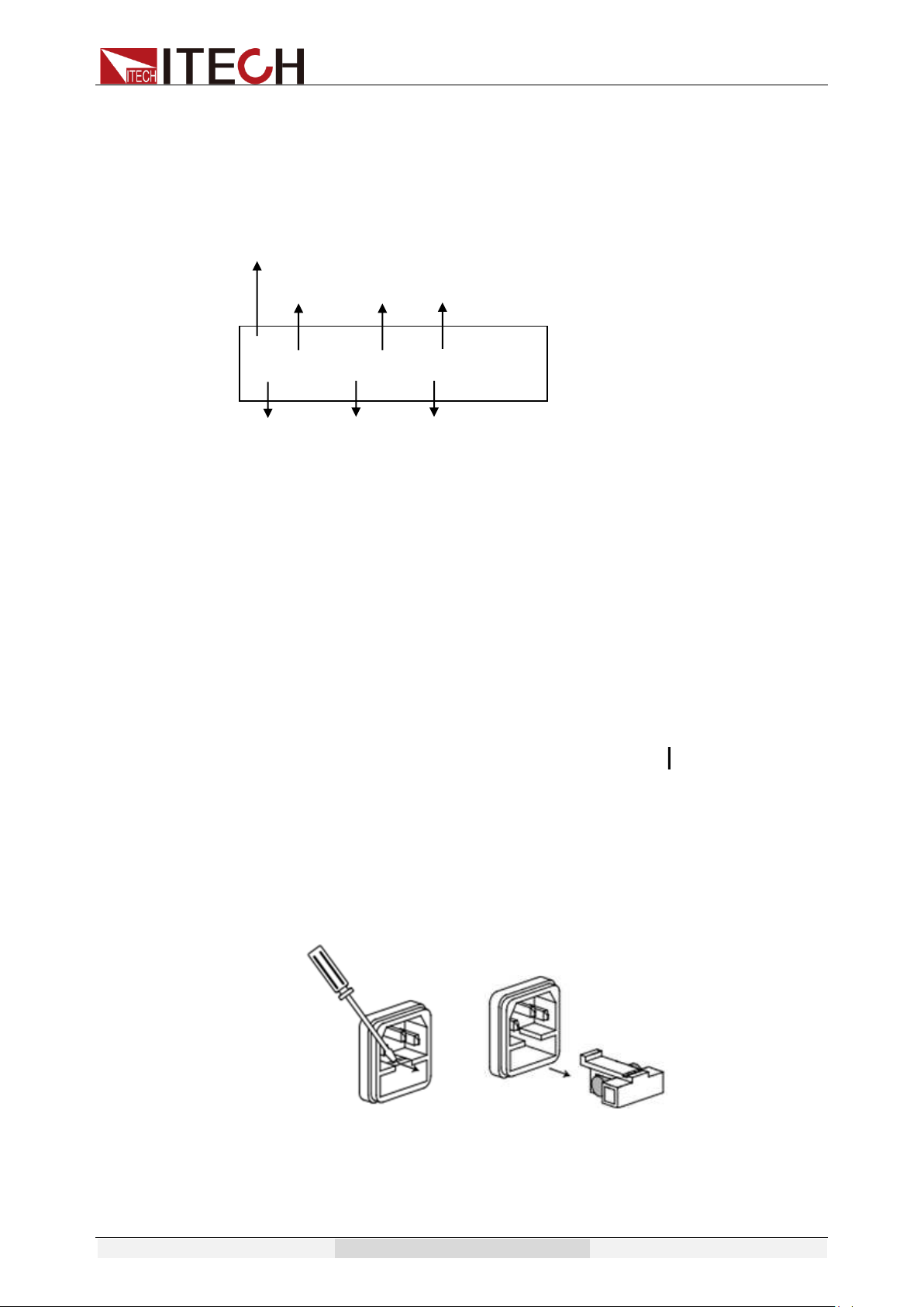
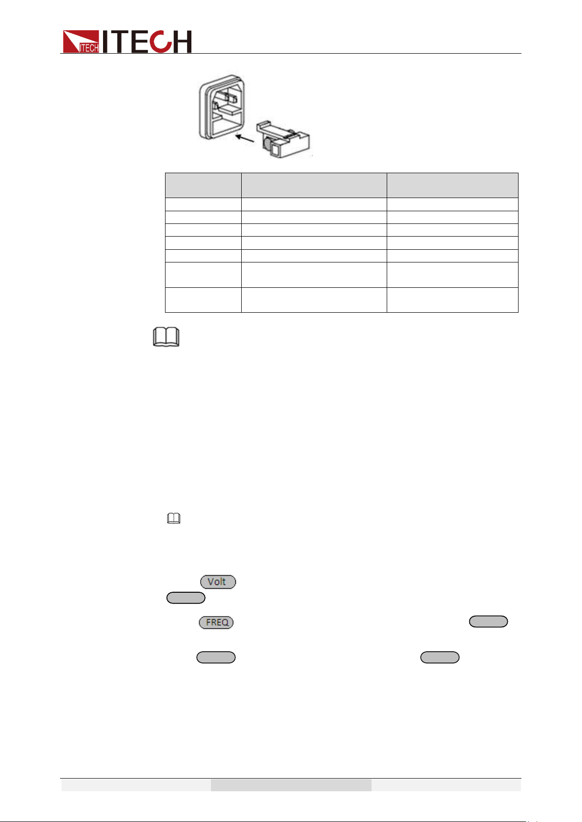
3. Check whether the fuse of power supply is burned out.
If yes, change fuse. Detailed steps: (Taking an example of IT7321):
1) Remove the AC power cord and open the plastic cover located at
the AC power inlet, then you will see the fuse.
2) Replace with a fuse of the same specification and install it.
OFF
200.0V 0.0mA 60.0
0.00W PF=0.000 0.0S
Effective power
Power factor
Output time
Output state
Effective
voltage
Current
Frequency
Quick start
Copyright © Itech Electronic Co., Ltd. 29
Fuse specification list:
Model
Fuse
specification(220VAC)
Fuse
specification(110VAC)
IT7321
6.3A
10A
IT7322
15A
30A
IT7322H
15A
30A
IT7324
30A
60A
IT7324H
30A
60A
IT7326
60A
Does not support
110VAC input
IT7326H
60A
Does not support
110VAC input
NOTE
Fuse of IT7326/IT7326H/IT7326T/IT7326HT can unscrew directly by hand. For fuse
position, see Introduction of Rear Panel for details. Remove the rear panel before
replacing the fuse of IT7326T/IT7326HT.
IT7322/IT7322H/IT7324/IT7324H/IT7322T/IT7322HT/IT7324T/IT7324HT fuse is inside
the power supply and must be replaced by professional personnel.
2.7 Voltage Output Checkout
The following procedures check to ensure that the power supply develops its
rated outputs and properly responds to operation from the front panel.
The following steps verify basic voltage functions without load.
1. Turn on the power supply.
Note
IT7322T, IT7322HT, IT7324T, IT7324HT, IT7326T and IT7326HT are assembled by
three single-phase instruments and can output three-phase AC power source. When
you operate the instrument which is set to Phase A, the other two instruments will
execute the same operation.
2. Press and numeric key to set an effective voltage, press
to confirm.
3. Press and numeric key to set the frequency, press to
confirm.
4. Press to turn on the output. Note: When button is lit
which means the output is ON, meanwhile indicator light of “OFF” on
VFD will disappear.
5. Check the output waveform with an oscilloscope. Set different
voltage and check whether the displayed voltage is close to setting
voltage.
6. Ensure that the voltage can be adjusted from zero to the full rated
value.
EnterEnter
EnterEnter
On/Off
On/Off
Function and Features
Copyright © Itech Electronic Co., Ltd. 30
Chapter3 Function and Features
This chapter introduces the basic operations of IT7300 series AC source.
IT7322T, IT7322HT, IT7324T, IT7324HT, IT7326T and IT7326HT are
assembled by three single-phase instruments and can output
three-phase AC power source. When you operate the instrument which
is set to Phase A, the other two instruments will execute the same
operation. The operations of the Phase A instrument are consistent with
those of the corresponding single instrument.
Including the following subdivisions:
⚫ Switching of local/remote operation modes
⚫ Voltage setup
⚫ Frequency setup
⚫ Phase angle setup
⚫ Output on/off operation
⚫ Switch the VFD display items
⚫ Save/recall operation
⚫ Trigger operation
⚫ Menu operation
⚫ Function operation
⚫ Output range
⚫ Key lock
⚫ BNC terminals function
⚫ 3-phase AC power supply function
3.1 Switching of Local/Remote Operation Modes
Press the local button to change the AC source from remote to local
operation. After you power on the AC source, it defaults in local mode, all
buttons are enabled. While in remote mode, most buttons are disabled except
Shift and Local keys. In addition, the mode modification will not affect the output
parameters.
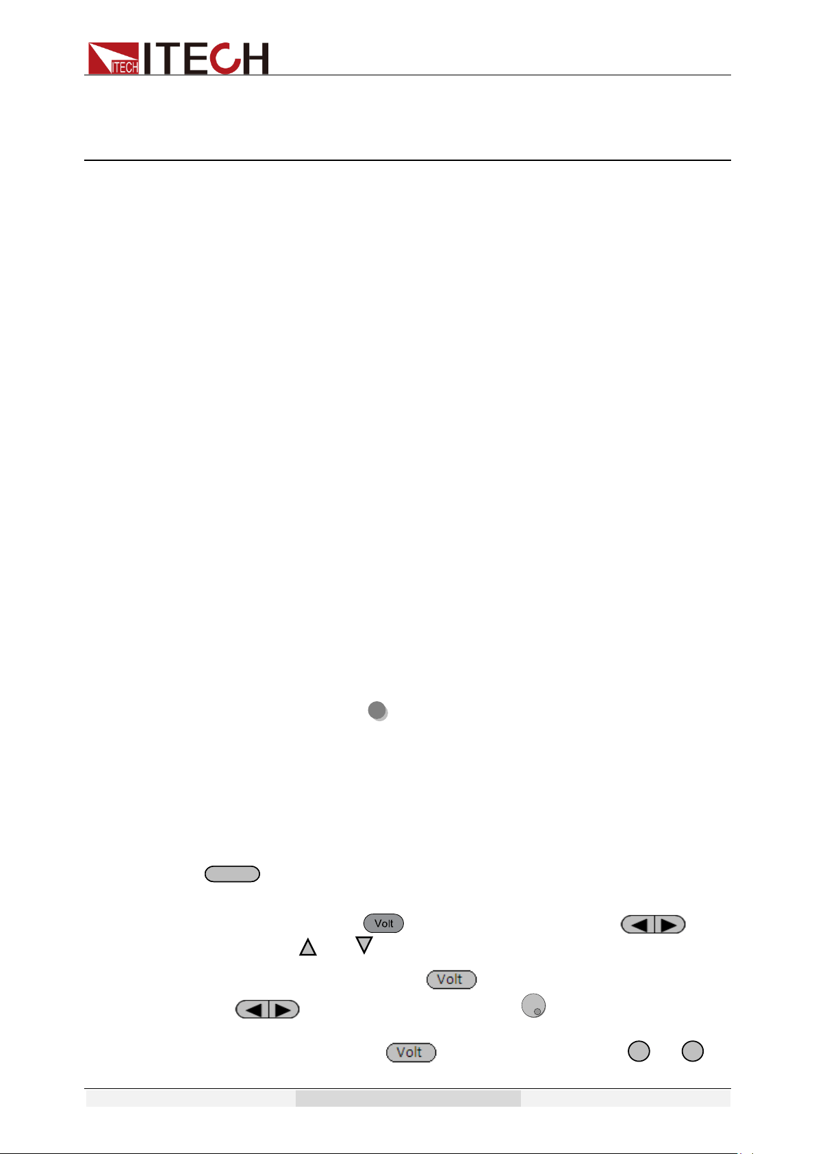
3.2 Voltage Setup
You can set voltage within the range of rated voltage value. When you press
button, the button will be lit. This indicates that you can set voltage.
There are three ways to set output voltage through front panel.
⚫ The first way: press , adjust cursor location through button,
pressing and will enable you to adjust the setting voltage value.
⚫ The second way: press , adjust cursor location through
button, adjust rotary knob to change the setting
voltage value.
⚫ The third way: press button and numeric key ( to ) to
set voltage value.
V-setV-set
0
9
Function and Features
Copyright © Itech Electronic Co., Ltd. 31
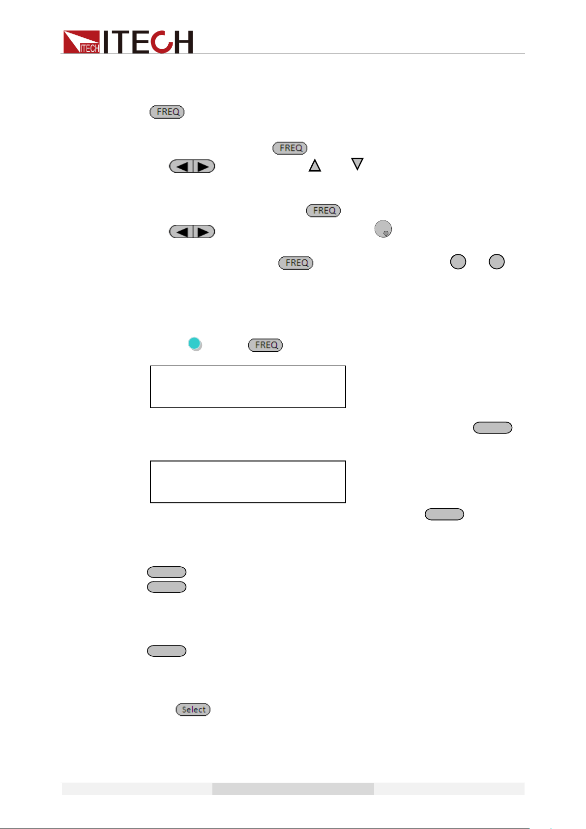
3.3 Frequency Setup
You can set frequency within the range 45Hz to 500Hz. When you press
, the button will be lit. This indicates that you can set frequency. There
are three ways to set frequency through front panel.
⚫ The first way: press , adjust cursor location through
button, pressing and will enable you to increase or
decrease the setting frequency value.
⚫ The second way: press , adjust cursor location through
button, adjust rotary knob to change the setting
frequency value.
⚫ The third way: press button and numeric key( to ) to
set frequency value
3.4 Phase Angle Setup
You can set the starting and stop phase angle within range of 0~360° by
pressing (Shift)+ (Phase),VFD will display as below:
Press numeric keys to set the starting phase angle and press to
confirm. Then the VFD will indicate next operation to set stop phase.
Press numeric keys to set the stop phase angle and press to confirm.
3.5 Output On/Off Operation
button is used to control the output state of AC source. When
button is lit, it indicates the output in on state. When output button is
dark which means the output is turned off.
Note:
make sure you have connected AC source and test DUT very well, then press
button to minimize shock hazard.
3.6 Switch the VFD Display Items
Press button to change the VFD display of bottom line.
Default VFD display: effective voltage, effective current, frequency
Active power, power factor, output time
0
9
Enter
Enter
On/Off
On/Off
On/Off
OFF
0.0V 0.0mA 50.0
Start Phase= 0.0° 0.6S
OFF
0.0V 0.0mA 50.0
Stop Phase= 0.0° 0.6S
Function and Features
Copyright © Itech Electronic Co., Ltd. 32
Press to switch the display:
effective voltage, effective current, frequency
apparent power, peak current, output time
Notes:
The time shown on the VFD is the output time of AC source. Press to
start the timing when power is on; press again to turn off power. The
duration of power supply will be displayed on the VFD until the next power
starts when the timer will reset. The timing is based on the decimal system:
when the time reaches 999.9 s, the timing will be displayed in minutes (m);
when the time reaches 999.9 m, the timing will be displayed in hours (h).
3.7 Save and Recall Operation
IT7300 series AC source provides10 non-volatile registers to save instrument
settings for recall later. Each operating state includes preset voltage, preset
frequency, starting and stop phase angle, output range level and dimmer phase
angle.
Press(Shift) + (Save) key to recall /save settings.
Save operation:
To save the instrument’s settings to a register, press shift +
(Save).You’ll be prompted for a register number. Enter a number between 0 and
9, then press the Enter key. The setting is saved.
Recall operation:
Press button, you’ll be prompted for a register number. Enter a
number between 0 and 9, then press the Enter key. The setting is recalled.
3.8 Trigger Operation
IT7300 power supply can be triggered by means of manual trigger (MENU),
command trigger (BUS) and external trigger (EXTERN). Manual trigger means
to trigger by keys; command trigger means to trigger through the
communication command when PC is used for control; and external trigger
On/Off
On/Off
Recall
Recall
Recall
OFF
0.0V 0.0mA 50.0
0.00W PF= 0.000 0.0S
OFF
0.0V 0.0mA 50.0
0.00VA 0.00Apk 0.0S
OFF
2.0V 0.0mA 50.0
Save data bank=0 0.0S
OFF
2.0V 0.0mA 50.0
Recall data bank=0 0.0S
Function and Features
Copyright © Itech Electronic Co., Ltd. 33
means to trigger by the BNC terminal at rear panel.
To trigger operation by the panel, you need to set the trigger operation mode
(TRIG) in the system menu to MENU. For details, see Section 3.9 Menu
Operation.
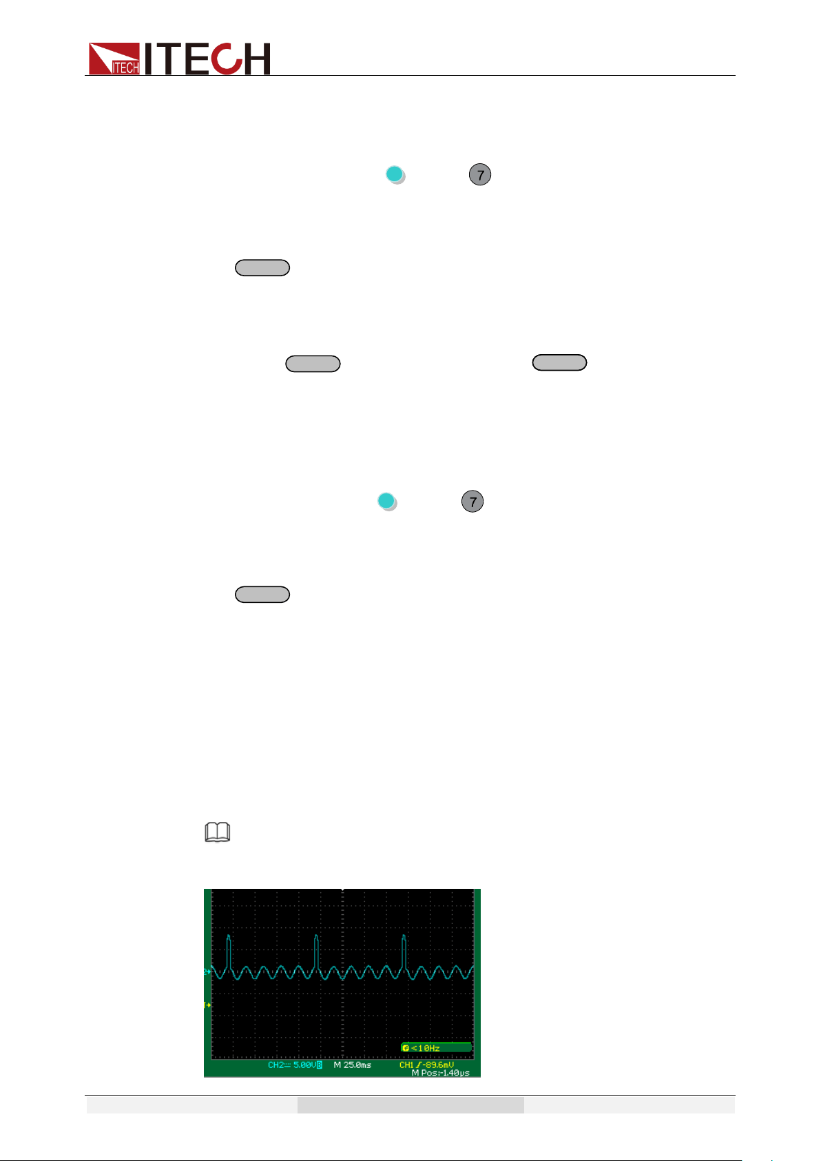
During surge/trapped wave test under List operation, press (Shift) +
(Trigger) to trigger surge/trapped wave. When LIST file is running, the
trigger function key (Trigger) will flick.
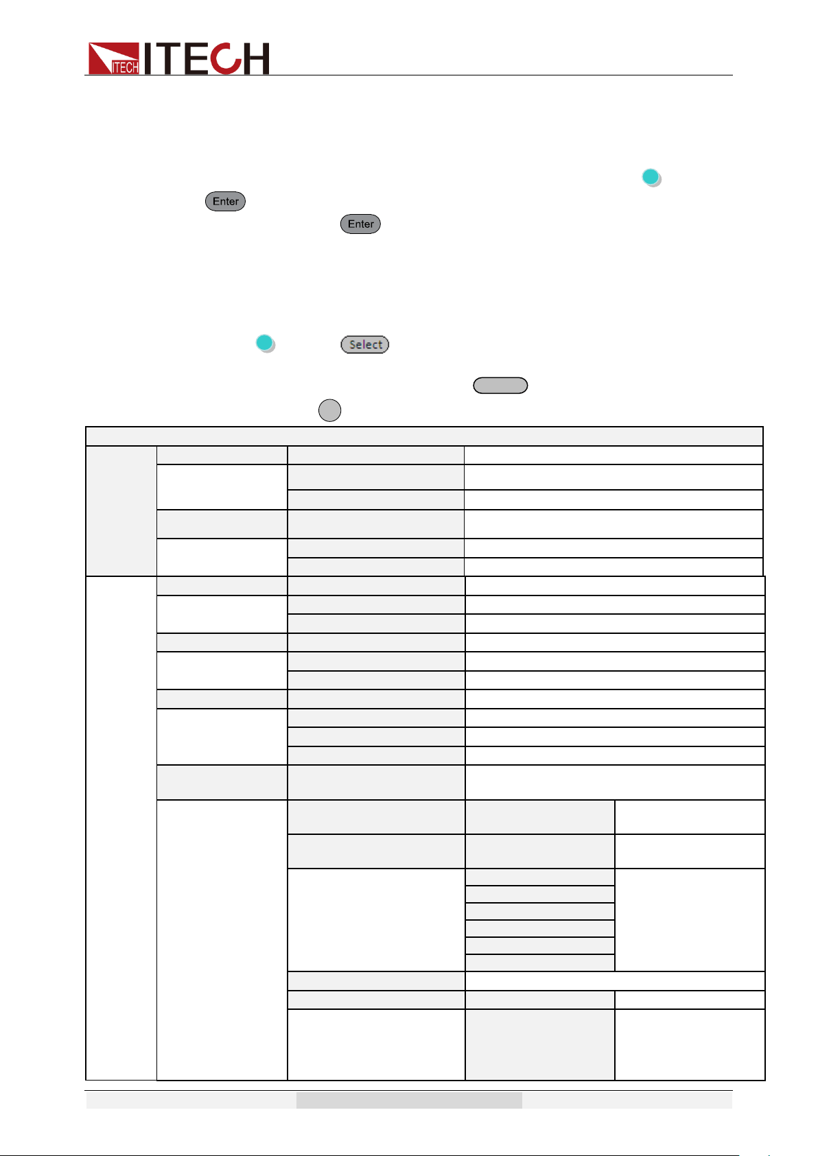
3.9 Menu Operation
3.9.1 Menu Description
Press (Shift)+ (Menu)to enter menu. View the menu on the
VFD, and use the direction keys or the knob to scroll through the
complete menu listed below. Press to enter the selected menu
function, press to return to the previous menu.
MENU
System
Init
INITIALIZE
Initialize system menu
Esc
Cancel initialization
Enter
Confirm initialization
Power-On
POWER-ON PARAMENT
Set the Power ON/OFF state after power up.
Sav0(Def)
The preset parameter stored in group 0
Rst
Factory Default
Power-Out
POWER-OUT
Power on state set
Off(Def)
In the state of power off
Last
In the state of latest power-off state
Buzzer
BUZZER
Set buzzer state
On(Def)
Buzzer on
Off
Buzzer off
Trigger
TRIGGER SOURCE
Trigger source selection.
Manual(Def)
Manual trigger
Bus
Bus trigger
Extern
External trigger
Communication
COMMUNICATION
Communication interface and parameter
setting
RS232(Def)
RS232
Select RS232
interface
GPIB
Address
Available range from
0-31
4800, 8, N, 1
Set Baud rate, data
bit, odd-even check,
stop bit and address
9600 O 2
19200 E
38400
57600
115200
USB
Select USB interface
LAN
LAN
Select LAN interface
Gateway=192.168.0.1
IP=192.168.0.125
Mask=255.255.255.0
Socket Port=30000
Set gateway, IP
address, mask
address and port.
Enter
ESC
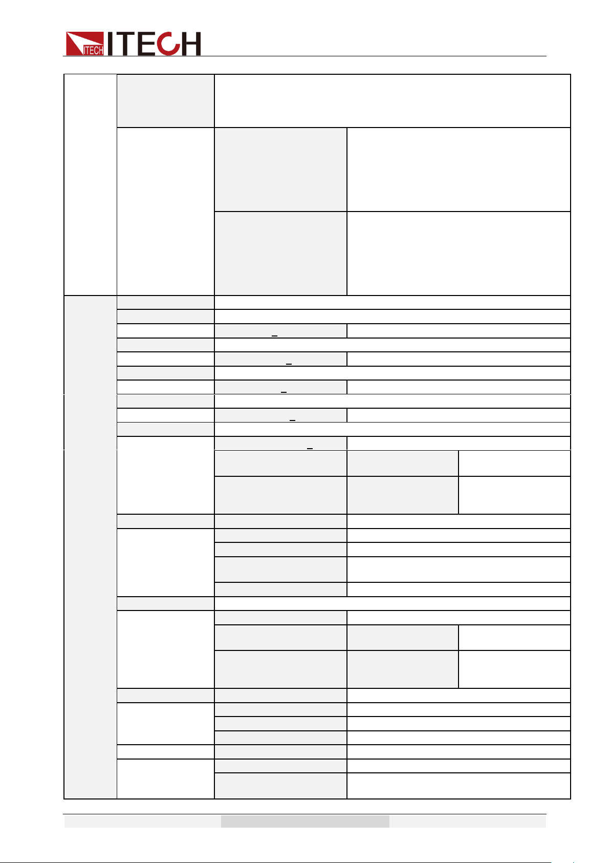
Function and Features
Copyright © Itech Electronic Co., Ltd. 34
RelayCtrl
It is used to control whether the switch status of the output relay is frequently
closed. When set to the Close state, the relay is always closed regardless of
whether the output is turned on or off, which is convenient for extending the
useful life of the relay.
Open
The switch status of the relay switches with the
state of the output.
⚫ When the output is turned on, the relay is
closed;
⚫ When the output is turned off, the relay is
disconnected.
Close
The switch status of the relay is frequently
closed.
⚫ When the output is turned on, the relay is
closed;
⚫ When the output is turned off, the relay is
closed.
Config
CONFIG
Config menu
Volt-Min
Voltage lower limit
Volt-Min=0.0V
Set Min. voltage
Volt-Max
Voltage upper limit
Volt-Max=300.0V
Set Max, voltage
Freq-Min
Frequency lower limit
Freq-Min=45.0Hz
Set frequency lower limit
Freq-Max
Frequency upper limit
Freq-Max=500.0Hz
Set frequency upper limit
Irms-Protect
Current RMS protect point
Irms-Protect=12.000A
Set current RMS protect point
Delay
Irms protection will
be triggered in 1s
Immediate
Protection will be
triggered
immediately.
BNC-Set
BNC PORT SETUP
I-Trigger
Input interface for external trigger
I-Ri
Input interface for on/off control
O-Sync
Output interface for AC phase
synchronization signal
O-On
Output interface for on/off state interface
Ipeak-Protect
Current peak protect point
Ipeak-Protect=12.000A
Set Current peak protect point
Delay
Irms protection will
be triggered in 1s
Immediate
Protection will be
triggered
immediately.
Dimmer
DIMMER
Phase dimmer
LeadingEdge
LeadingEdge Phase dimmer function
TrailingEdge
TrailingEdge Phase dimmer function
Off
Disable Phase dimmer function
List-Set
LIST START MODE
List start mode
On/Off
Press On/Off to start/stop running
Trigger
Press Shift + Enter (Trigger) to start/stop
running
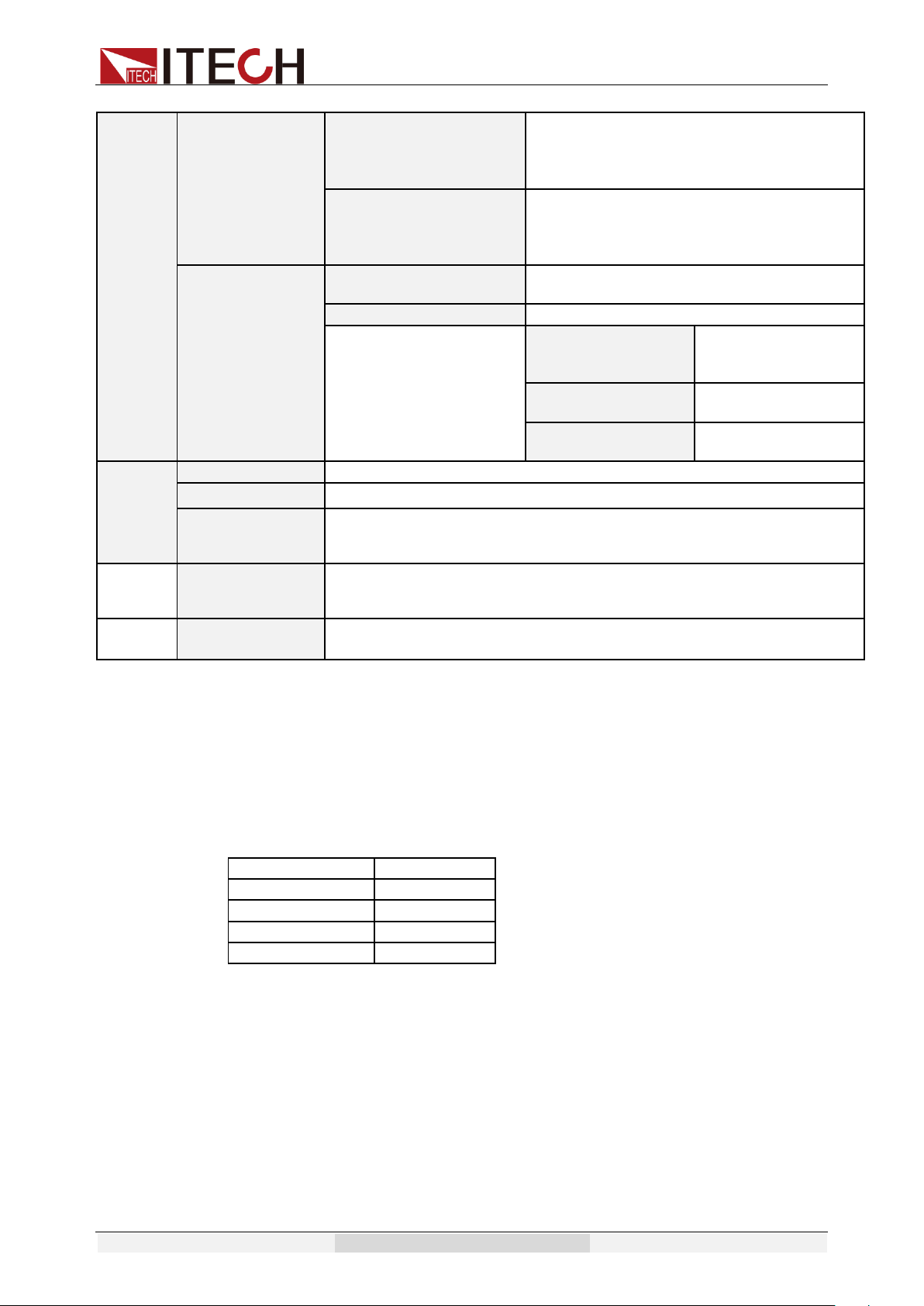
Function and Features
Copyright © Itech Electronic Co., Ltd. 35
3ø-Setup
A-Phase/ B-Phase /
C-Phase
Set the power supply to A-Phase, B-Phase
or C-Phase of AC power supply, with
difference of 120 degrees between any two
phases.
Disable/Enable
Turn on or turn off three-phase output
function.
To achieve this function, user need to
combine three units.
Meas- Curr-mode
Auto
Select automatic current measurement
mode
Manual
Select manual current measurement mode
High
Select high-range
current
measurement
Middle
Select mid-range
measurement
Low
Select low-range
measurement
Info
PRODUCT INFO:
Power information
ERROR INFO:
For look up error information
PRODUCT INFO:
IT73XX
Ver:0.01~0.01
Instrument type/Firmware version
PRODUCT SN:
XXXXXXXXXX
XXXXXXXX
Instrument SN
RECORD INFO:
Record information
Notes:
IT7321 has no GPIB and 3ø-Setup menu items.
3.9.2 Menu Function
Initialize the system menu
Relative factory default setup as follows:
Power-On
Sav0
Power-Out
Off
Buzzer
On
Trigger
Manual
Communication
RS232
Power-On
This parameter determines the state of the AC source after power up. If you
select “Rst”, the default output parameter settings will be active after power up.
The default setup is 0V,50HZ, 0° and 0°. If you select “Sav0”, then the AC
source will automatically recall the output parameters setting saved in 0 register
Note, please save these parameters in memory0 according to 3.7.
Power-Out
This parameter sets the output on/off state at power up. If you select “Last”, the

Function and Features
Copyright © Itech Electronic Co., Ltd. 36
AC source will save the output state prior to power down and revert to that state
at power up. If you select “off”, the output state is always “off” when the power
supply is turned on. The recommend setting is “OFF”.
Buzzer
This item can set the key sound state. If in ON mode, then when you press a
button, the power supply will beep. If in OFF mode, the beeper will not make a
sound. The default set is in ON mode.
Trigger source
This item can set the trigger signal to Keyboard trigger, Command trigger or
External trigger during surge/trapped wave test under List operation. If Manual
is selected, the trigger signal is provided by (Shift) + (Trigger) on
the panel; if Bus is selected, command trigger mode is used; if External trigger
is selected, the trigger signal is provided by the trigger terminal (BNC) at the
rear panel. BNC is a composite terminal. You need to set its function to I-Trigger
in the Menu. For details, refer to Section 3.13 BNC. Set Factory Setting to
Manual.
Setting of Communication Interface
This item can set communication modes of the power supply. IT7321 has the
following standard communication interfaces: LAN/USB/RS232; and the others
have the following standard communication interfaces: LAN/USB/RS232/GPIB.
You can choose any one of them to communicate.
RS232 Baud rate: 4800/9600/19200/38400/57600/115200. Data bit: 8; check
bit: NONE, ODD, EVEN; stop bit: 1~2;
LAN parameters include Gateway address (Gateway), IP address (IP), Mask
address (Mask) and port (Socket Port).
When communication with computer, you need to select a communication
interface and set its corresponding configurations so that the communication
settings of the power supply are same with the PC configurations.
Config menu
The configuration menu is described below:
Volt-Min:
Voltage lower limit setting
Volt-Max:
Voltage upper limit setting
Freq-Min:
Frequency lower limit setting
Freq-Max:
Frequency upper limit setting
Irms-Protect:
Current RMS upper limit setting
BNC-Set:
Select BNC composite terminal function
Ipeak-Protect:
Peak Current upper limit setting
Dimmer:
Set phase dimmer
List-Set
Select List start mode
3ø-Setup
Set 3-phase AC power supply function
Meas-Curr-mode
Switch current measurement mode
Switch current measurement mode (Meas-Curr-mode)
This item can set the current measurement mode of the power supply. IT7300

Function and Features
Copyright © Itech Electronic Co., Ltd. 37
series has two measurement modes: Auto and Manual. When Auto mode is
chosen, the switchover among High range, Middle range and Low range will be
performed by the instrument automatically. When Manual mode is chosen, the
switchover among High range, Middle range and Low range will be performed
by the user manually.
Check instrument information
1. Press (Shift)+ (Menu)to enter menu operation
Off
0.0V 0.0mA 50.0
0.00W PF=0.000 0.0S
2. Press right direction key to select INFO, press to confirm
MENU
System Config Info
3. VFD displays product model and firmware version number. Press
right key to display product serial number.
PRODUCT INFO:
IT73XX Ver:0.06~0.06
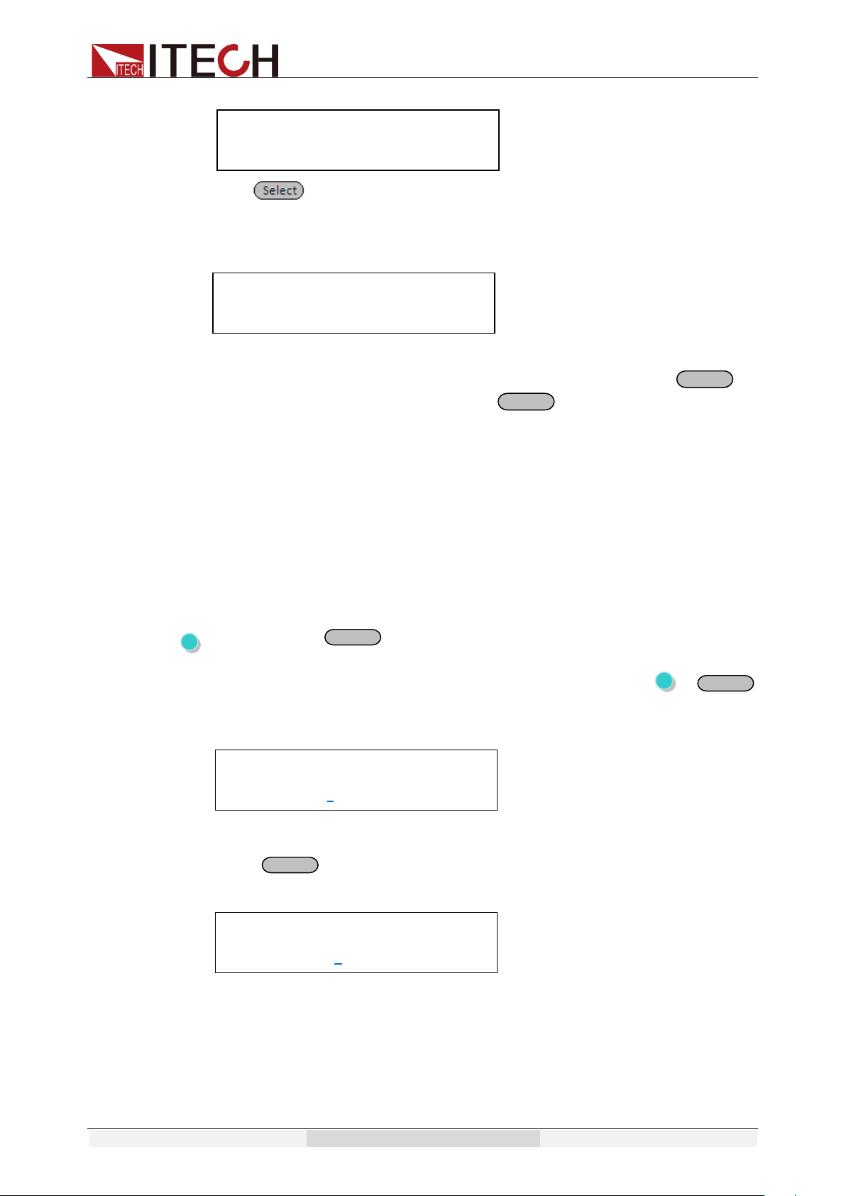
3.10 Function Operation
3.10.1 Sweep
The Sweep function is used to test efficiency of switching power supply and
capture the voltage and frequency at the maximum power point. The voltage
and frequency of power may be altered in the form of step ladder by setting the
initial voltage, final voltage, step voltage, initial frequency, final frequency, step
frequency and one-step time. The one-step time may be indicated in seconds,
minutes or hours. A maximum of 10 files may be stored. As the test closes,
voltage, frequency and current at the maximum power point may be displayed.
Note
This feature is not available in the three-phase model.
> Edit sweep file
NOTE
In the following operations, up and down keys are used to turn over steps, but
not to increase or decrease value. When up arrow appears in the lower left
corner, you can press the up key to jump to the previous step. When down
arrow appears in the lower right corner, press down key can entry the next step.
1. Press (Shift)+ (Sweep)to enter menu operation
Off
0.0V 0.0mA 50.0
0.00W PF=0.000 0.0S
2. Press to confirm when Edit is shining.
SWEEP
Edit Recall Disable
3. Press number key or knob to set start voltage, press to
confirm
START VOLTAGE
Voltage= 0.0V
Enter
Enter
Enter
Function and Features
Copyright © Itech Electronic Co., Ltd. 38
4. Press numeric key or knob to set stop voltage, press to
confirm
END VOLTAGE
Voltage= 0.0V
5. Press numeric key or knob to set step voltage, press to
confirm
STEP VOLTAG
Voltage=0.1V
6. Press left and right arrow keys to select time unit second, minute and
hour, press to confirm.
TIME UNIT
Second Minute Hour
7. Set step last time(0.1s~999.9s), press to confirm
STEP TIME
Time=2.0S
8. Set start frequency(45Hz~500Hz), press to confirm
START FREQUENCY
Frequency=50.0Hz
9. Set stop frequency(45Hz~500Hz), press to confirm
END FREQUENCY
Frequency=50.0Hz
10. Set step frequency, press to confirm
STEP FREQUENCY
Frequency=1.0Hz
11. Press left and right arrow keys to select whether save sweeping file,”
No” means do not saving,” Yes” means saving.
SWEEP SAVE
No Yes
12. Select save position(0~9), press to confirm, VFD display
“Save Data success!“ for 1 second.
SWEEP SAVE
Save data bank=0
13. Return to Previous Menu and press to exit menu.
SWEEP
Edit Recall Disable
> Recall sweep file
1. Press multiple keys (Shift)+ (Sweep) to menu operation
Off
0.0V 0.0mA 50.0
0.00W PF=0.000 0.0S
2. Press right arrow key then press key to confirm when
Recall key is shining.
SWEEP
Edit Recall Disable
3. Press numeric key to select needed recall file and press
key to confirm. VFD display “Recall Data success! “ for 1 second.
RECALL SWEEP
Recall Sweep=0
4. Return to Previous Menu and press to exit menu.
SWEEP
Enter
Enter
Enter
Enter
Enter
Enter
Enter
Enter
Enter
Enter
Function and Features
Copyright © Itech Electronic Co., Ltd. 39
Edit Recall Disable
> Set sweep test state and start test
1. Press multiple keys (Shift)+ (Sweep) to menu.
Off
0.0V 0.0mA 50.0
0.00W PF=0.000 0.0S
2. Press right arrow key to “Disable”, press down arrow key and
to infirm when “Disable” is shining. The word ”Sweep”
appears at the right bottom, which means the Sweep function is
active.
SWEEP
Edit Recall Disable
3. Press key to start sweep test. key will be shining
during test and will stop after that with power off automatically.
Off
0.0V 0.0mA 50.0
0.00W PF=0.000 Sweep
After the test is finished, to exit Sweep function, you need to change the Sweep
test status to Disable. Operating steps:
1. Press multiple key (Shift)+ (Sweep) to menu operation.
Off
0.0V 0.0mA 50.0
0.00W PF=0.000 0.0S
2. Press right arrow key to “Enable”, press down arrow key and
key to confirm and then exit sweep function (Sweep words
will disappeared on lower right of VFD display )
SWEEP
Edit Recall Enable
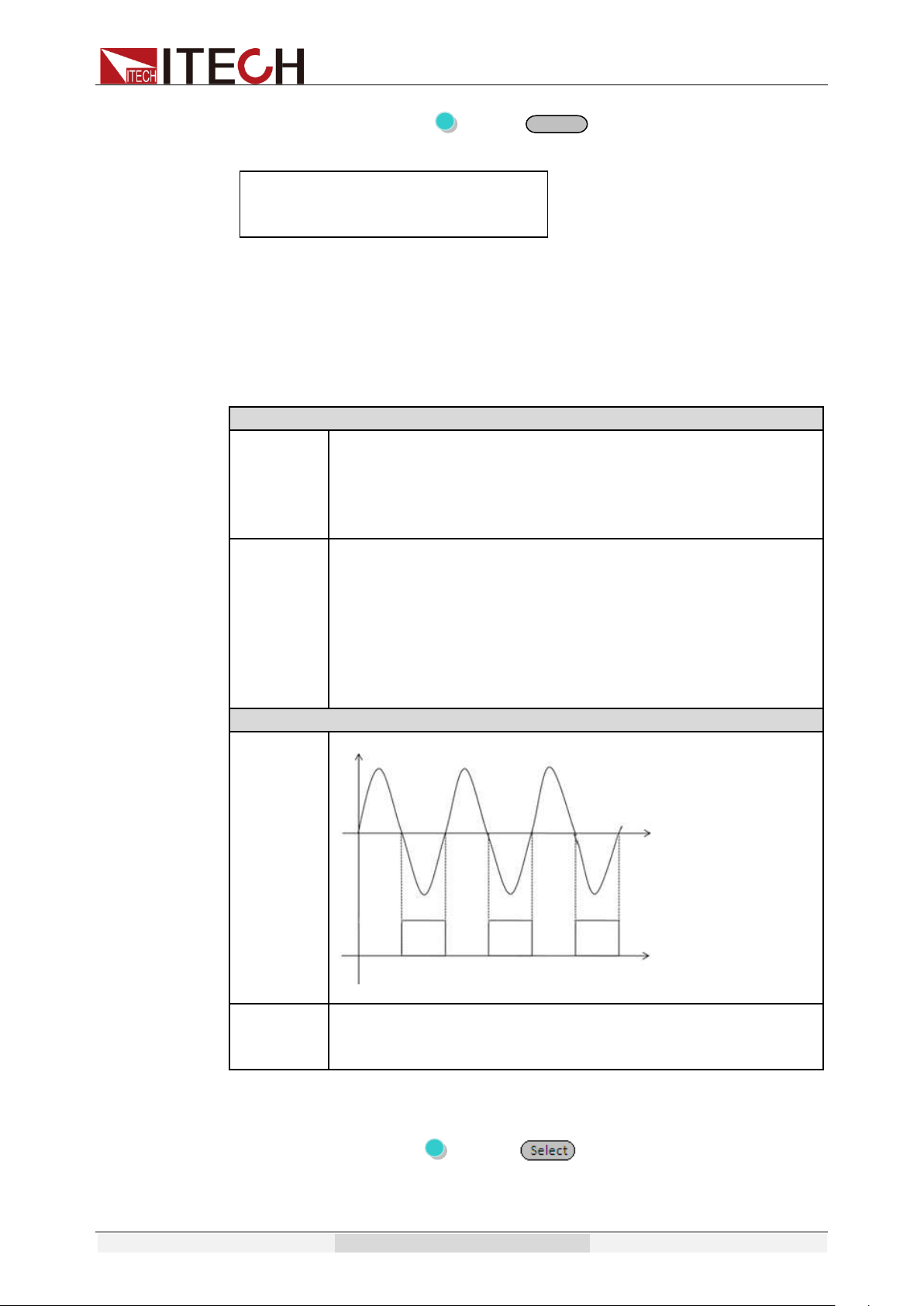
3.10.2 List Operation
With List operation applied to the alternating power supply, alternating
waveform sequences in various ranges may be output. The surge/trapped
wave may be added as required to simulate fluctuation of network voltage so as
to evaluate the test result of the instrument under such situation.
Various alternating sequences with output varied may be formed by listing the
voltage, frequency, slope, surge/trapped wave each step.
Note
This feature is not available in the three-phase model.
Enter
On/Off
EnterEnter
Enter
Function and Features
Copyright © Itech Electronic Co., Ltd. 40
Surges wave
List sequences of IT7300 series can be stored into a non-volatile register, with a
capacity of 100 steps. The user can edit up to 10 files. Following shows how to
edit, recall and run a list file:
> Set Trigger Source
The surge/trapped wave test of LIST may be manually triggered to
control the start time of the surge/trapped wave.
Press (Shift)+ (Menu) to entry the menu. Then the system
will keep flickering------press to confirm. Press right key to select
Trigger. When selected, trigger item will be twinkling. Press to
confirm. Press right key to select Manual and press to confirm.
> Edit LIST File
1. Press (Shift)+ (List) button.
Off
0.0V 0.0mA 50.0
0.00W PF=0.000 0.0S
2. Select Edit, press to confirm.
LIST
Edit Recall Disable
3. Press numeric key, set the step counts(range:1~100), press
to confirm.
STEP COUNT
Step Count=0
4. Press numeric key, set number of cycles(range:1~1000), press
to confirm.
LIST REPEAT
List Repeat=0
5. Set the first step voltage and press to confirm.
LIST VOLTAGE
Step 0 Voltage=0.0V
6. Set the first step frequency and press to confirm.
LIST FREQUENCY
Step 0 Frequency=50.0Hz
7. Set the slope(0.1~999.9),press to confirm.
LIST SLOPE
Step 0 Slope=0.0S
8. Set the time unit: S, min, hour, press to confirm.
DWELL UNIT
Second Minute Hour
9. Set delay time(0.1~999.9),press to confirm.
LIST DWELL
Step 0 Dwell=0.0S
10. Disable or enable the surges or trap state, press to confirm. If
select Disable, then do nothing for step11-step14.
SD STATE
Disable Enable
11. Press left/right key to set whether create surges/wave traps
Enter
Enter
Enter
8
Enter
Enter
Enter
Enter
Enter
Enter
Enter
Enter
Enter
Function and Features
Copyright © Itech Electronic Co., Ltd. 41
continuously. If select Yes, power supply will create surges/wave
traps in at intervals of 100ms.Press to confirm.
SD CONTINUE
No Yes
12. Press numeric keys to set voltage of surges/wave traps, press
to confirm. If set voltage is higher than current working
voltage, then it is surges, or it is wave traps.
SD VOLTAGE
Step 0 Voltage=0.0V
13. Set the starting time of surges/wave traps, press to confirm.
With the restriction of frequency, the max settable time is 25ms.
SD SITE
Step 0 Site= 0ms
14. Set the duration time of surges/wave traps. Press to
confirm.
SD TIME
Step 0 Time=0ms
15. Repeat step4-13.
LIST VOLTAGE
Step 1 Voltage=0V
16. NO: Do not save the list file, after power off the unit, current file will
lose. Yes: Save list file to assigned memory room for quickly recall at
any time.
LIST SAVE
No Yes
17. Store file to specified storage space(0~9 groups), press to
confirm. VFD will display “Save data success!”
LIST SAVE
Save data bank=0
> Set LIST State
1. Press (Shift)+ (List) to entry the List menu.
Off
0.0V 0.0mA 50.0
0.00W PF=0.000 0.0S
2. Press right key to select Disable, when it flickers, press up/down key
to select Enable, and press to confirm.
LIST
Edit Recall Disable
3. Now the List mode is enabled. Escape menu, the front panel will
display “LIST 0”.
LIST
Edit Recall Enable
4. List mode is enabled
Off
0.0V 0.0mA 50.0
0.00W PF=0.000 List 0
> Run LIST File
When LIST is in Enable status, exit menu.
⚫ If List-Set under Config menu is set to On/Off: Press key to turn on
Enter
Enter
Enter
Enter
Enter
8
Enter
Function and Features
Copyright © Itech Electronic Co., Ltd. 42
power supply output, and LIST file starts running. Press to stop
running.
⚫ If List-Set under Config menu is set to Trigger: Press (Shift)+
(Trigger) key to trigger and the LIST file starts running. Press (Shift)+
(Trigger) again to stop running.
List running flag: When List is running, is flicking, and LIST step
displayed at the right bottom of VFD will also change by setting as time
elapses.
> Quit LIST Mode
1. Press (Shift)+ (List) to entry the List menu.
Off
0.0V 0.0mA 50.0
0.00W PF=0.000 0.0S
2. Press right key to select Enable, when it flickers, press up/down key
to select Disable, and press to confirm. Indicating List mode
is disabled.
LIST
Edit Recall Enable
3. Press to quit the List menu.
LIST
Edit Recall Disable
> Recall LIST Mode
If several List files are edited, you can recall the List file to be tested by Recall.
When LIST is in Enable status, exit the menu to perform test.
1. Press (Shift)+ (List)button to entry the List menu
Off
0.0V 0.0mA 50.0
0.00W PF=0.000 0.0S
2. Press right key to select Recall, when it flickers, press to
confirm.
LIST
Edit Recall Disable
3. Press the file number to recall the assigned file. Press to
confirm. when recall successfully, the VFD will display ”Recall data
success!”.
RECALL LIST
Recall List=0
4. Return to Previous Menu and press to exit menu.
LIST
Edit Recall Disable
5. After recall, please enable the LIST state, then quit the menu and
press ON/OFF to trigger the execution.
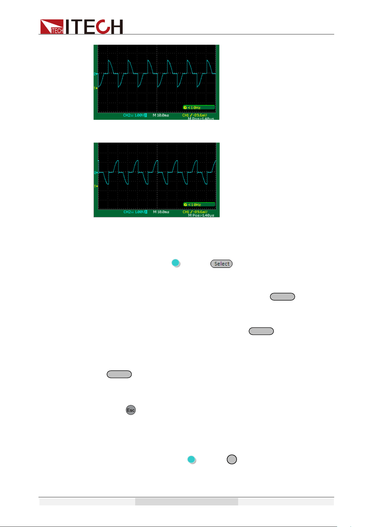
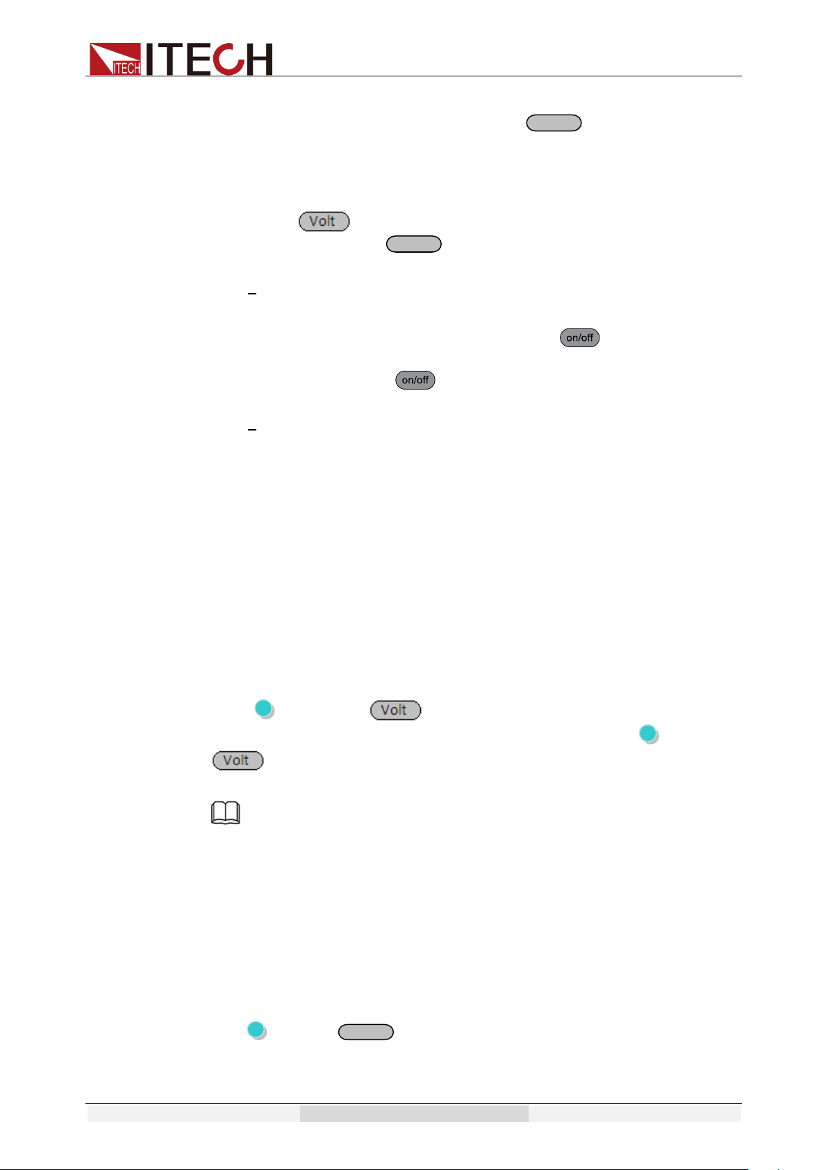
3.10.3 Dimmer
The leading and lagging edge of the waveform can by concealed and the
phase angle set with Dimmer function to regulate the active power, thus
adjusting the lighting intensity.
8
Enter
8
Enter
Enter
Function and Features
Copyright © Itech Electronic Co., Ltd. 43
Dimmer of leading edge
Dimmer of lagging edge
> Active dimmer function, set LeadingEdge /LaggingEdge
1. Press multiple keys (Shift)+ (Menu)to menu
Off
0.0V 0.0mA 50.0
0.00W PF=0.000 0.0S
2. Press right arrow key to select “ Config”, press to confirm
when “Config” is shining
MENU
System Config Info
3. Press right arrow key to “Dimmer” press to confirm when
“Dimmer” is shining.
CONFIG
Volt-Min Volt-Max >
4. Select “LeadingEdge” or “LaggingEdge” to active the function. Press
key to confirm when it is shining. Shining”*” indicate on
VFD means dimmer function is in used, conversely,”*” disappeared.
DIMMER
LeadingEdge TrailingEdge Off
5. Press to quit the menu.
DIMMER
LeadingEdge TrailingEdge Off
> Set phase angle and start test
1. Press compound key (Shift)+ (*Dimmer) and enter menu
operation
Off *
0.0V 0.0mA 50.0
Enter
Enter
Enter
9
Function and Features
Copyright © Itech Electronic Co., Ltd. 44
0.00W PF=0.000 0.0S
2. Press numeric key to set angle, press to confirm. Also you
can adjust angle by knob to view real-time waveform changes along.
Off *
0.0V 0.0mA 50.0
Dimmer=30.0° 0.1S
3. Press and numeric key to set voltage based on
requirement. Press to confirm.
Off *
0.0V 0.0mA 50.0
0.00W PF=0.000 0.0S
4. Confirm that both List and Sweep are in Disable status (VFD
appears no words of List or Sweep). Press to turn on Output.
The power supply starts outputting phase dimmer wave, and the “*”
on VFD flicks. Press again to stop output.
Off *
0.0V 0.0mA 50.0
0.00W PF=0.000 0.0S
3.11 Output Range
IT7300 series AC source will allow switchover between High range and Auto
range. Take IT7321 as example, the voltage, current and apparent power at the
High range is 300V/1.5A/300VA; the voltage, current and apparent power at the
Low range is 150V/3A/300VA. Auto range refers to auto switchover mode
between High range and Low range.
You can choose the range according to actual test requirements. When Auto
range is chosen, the switchover between High range and Low range will be
performed by the instrument automatically, thus sparing complicated operations
such as manual setting.
Switch High range and Auto range:
Press (Shift) and (High/Auto) together to switch between High
range and Auto range. When High range is chosen, press the (Shift) and
(High/Auto) together to switch to Auto range. The indicator “Auto” on
the VFD will be on.
Note
There is a temporary OFF to the AC source during the switchover of range.
3.12 Key Lock
The front panel keys can be locked to prevent unwanted changes to output
settings and AC source configurations. Follow the steps below to
enable/disable key lock.
Press ( (Shift)+ (Lock) button to set the key lock state. If keyboard
has been locked, the indicator light ”Lock” will display on the VFD. In addition,
when keyboard is locked, all buttons can’t be used except ON/OFF key, Shift
Enter
Enter
On/Off
Function and Features
Copyright © Itech Electronic Co., Ltd. 45
key and Select key. Press (Shift)+ (Lock) once again will relieve
key lock function.
3.13 BNC
There is a composite terminal at the rear panel of the AC source (see
description of rear panel), which can be used as:
Input signal:
I-Trigger
Serve as input signal by external trigger. Connect the
positive and negative end of the terminal to generate a
trigger signal. To use this function, you need to set the
Trigger item under System menu to Extern (External
Trigger).
I-Ri
Serve as the control signal for On/Off. When the positive
and negative end of the terminal is in short circuit, the
status of AC source is OFF; when the circuit is open, the
status of AC source is ON.
Note: Only when the front panel and BNC are set to On at
the same time, the power supply outputs. Otherwise, the
power supply is OFF.
Output signal:
O-Sync
as synchronizing signal of alternating phase:
O-On
as status signal for On/Off. When the status of AC source
is ON, the terminal will output high level; when the status
of power supply is OFF, the terminal will output low level
Before using BNC terminal, you need to define its function firstly by following
steps below:
1. Press multiple key (Shift)+ (Menu) to menu operation.
Off
0.0V 0.0mA 50.0
0.00W PF=0.000 0.0S
On/Off
OFF
0.0V 0.0mA 50.0
0.00W PF=0.000 Lock
Function and Features
Copyright © Itech Electronic Co., Ltd. 46
2. Press right arrow key and select “config”, press key when
“Config” is shining.
MENU
System Config Info
3. Press right arrow key to BNC-Set and press key when
“BNC-Set” is shining.
CONFIG
V-Min V-Max >
4. Press left and right arrow keys to select interface function and press
. Press ESC key to exit menu.
BNC PORT SETUP
I-Trigger I-Ri O-Sync O-On >
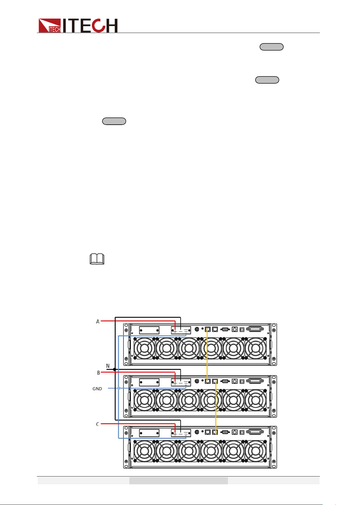
3.14 3ø-Setup
IT7322/IT7322H/IT7324/IT7324H/IT7326/IT7326H supports 3-phase output via
three units. The three units need to be connected together via SYSTEM BUS to
achieve 3-phase output function of AC power supply.
The IT7322T, IT7322HT, IT7324T, IT7324HT, IT7326T and IT7326HT can
output the three-phase AC power source and are assembled by three
single-phase instruments. Furthermore, the three single-phase instruments of
the three-phase power supply are set to Phase A, Phase B and Phase C
before shipment. Therefore, the following operations don’t apply to the
three-phase power supplies.
NOTE
After being assembled into three-phase, the List and Sweep functions
will not be available.
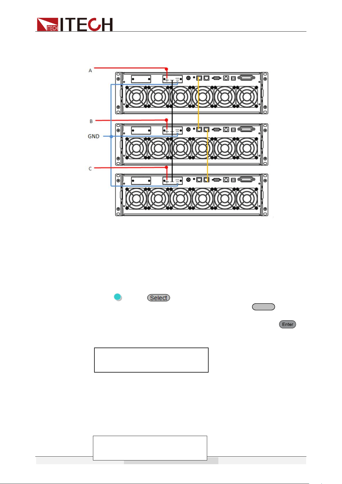
Take IT7324 as example for description. 3-phase output includes two
connection types of “Y” or “Delta”.
⚫ Y type connection:
Enter
Enter
Enter
Function and Features
Copyright © Itech Electronic Co., Ltd. 47
⚫ Delta connection:
SYSTEM BUS: User need to connect three units together via a straight network
cable. Please see figure above.
Select one connection method as shown above. After wiring, set 3 power
supplies to Phase A, Phase B and Phase C respectively. Phase A power supply
will automatically search for Phase B and Phase C power supplies. Detailed
operation steps are shown below:
Set Phase A
1. Press (Shift)+ (Menu)to enter the menu operation.
2. Press right-key to select CONFIG, then press button to
confirm.
3. Press left and right arrow keys to select 3ø-Setup. Press to
enter configuration of 3-phase AC power supply function. Interface
displays as below:
Two parameters need to be set from the menu to enable this function:
A-Phase/ B-Phase / C-Phase Configure the phase line of each unit
Disable/Enable Turn on or turn off 3-phase function
Press right key to select item to be set and press Up/Down key to select.
4. After setting of Phase A, press [Esc] to return to the Main Interface,
which displays as follows:
Enter
OFF
3ø-Setup
A-Phase Disable
OFF Auto
0.0V 0.0mA 50.0
0.00W 3ø-B,C Loss 3ø-A
Function and Features
Copyright © Itech Electronic Co., Ltd. 48
Set Phase B/C
Follow same setting steps 1-3 of Phase A to set Phase B/C. After setting of
Phase B/C, press [Esc] to return to the Main Interface. Take Main Interface of
Phase B as example, as shown below.
After setting of Phases B and C, the main interface of Phase A power supply
displays as follows:
Note
When you operate the instrument which is set to Phase A, the other two instruments will
execute the same operation.
OFF Auto
0.0V 0.0mA 50.0
0.00W PF=0.000 3ø-B
OFF Auto
0.0V 0.0mA 50.0
0.00W 3ø-B,C Loss 3ø-A
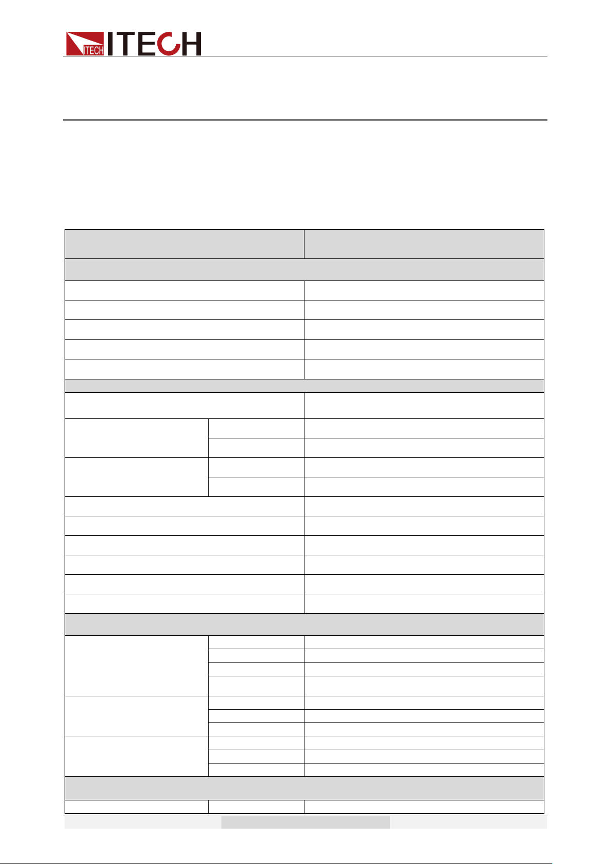
Specification
Copyright © Itech Electronic Co., Ltd. 49
Chapter4 Specification
This chapter will introduce the main technical parameters of IT7300, such as
rated voltage/current/power and so on. Besides, this part will introduce the
working environment and storage temperature.
4.1 Specification
Model
IT7321
INPUT
Phase
1
Voltage
220Vac±10% or 110Vac±10%
Frequency
47-63Hz
Max.Current
6.3A(220Vac) or 10A(110Vac)
Power Factor
0.5(typical)
AC OUTPUT
Max.Power
300VA
Max Current(rms)
0-150V
3A
0-300V
1.5A
Max Current(peak)
0-150V
9A
0-300V
4.5A
Phase
1Φ/2W
Total Harmonic Distortion(T.H.D)
≤0.5% at 45-500Hz (Resistive Load)
Crest Factor
3
Line Regulation
0.1% max for a ±10% line change
Load Regulation
≤0.5%FS(Resistive Load)
Response Time
<100uS
SETTING
Voltage
Range
0-300V High, 150/300V Auto
Resolution
0.1V
Accuracy
±(0.2%+0.6V)
Temp. coefficient
±(0.04% per degree from 25℃)
Frequency
Range
45-500Hz
Resolution
0.1Hz at 45-99.9Hz 1Hz at 100-500Hz
Accuracy
0.1Hz
Phase Angle
Range
0-360°
Resolution
0.1°
Accuracy
±1°(45-65Hz)
MEASUREMENT
Voltage(rms)
Range
0-300V
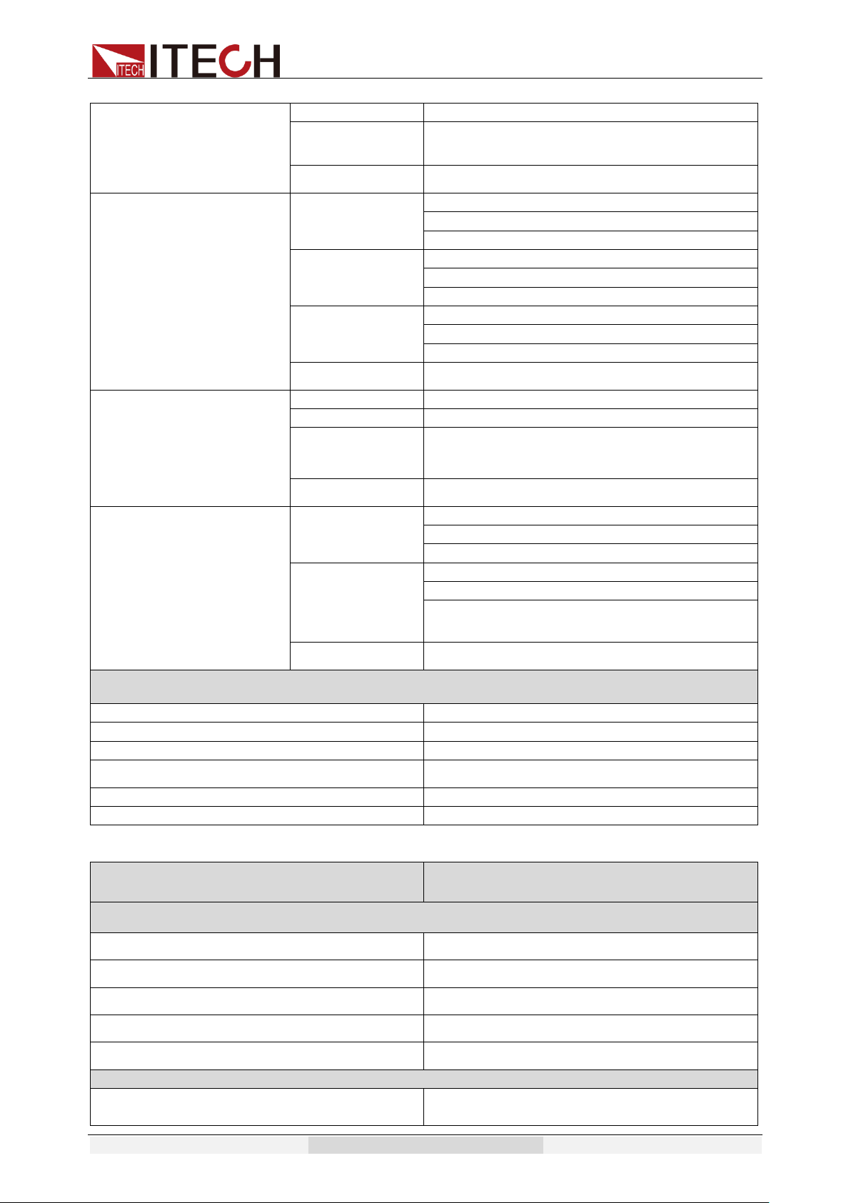
Specification
Copyright © Itech Electronic Co., Ltd. 50
Resolution
0.1V
Accuracy
±(0.2%+0.6V)
Temp. coefficient
±(0.04% per degree from 25℃)
Current(rms)
Range
L:120.0mA *
M:1.200A *
H:3.00A *
Resolution
L:0.1mA
M:1mA
H:10mA
Accuracy
L:±(0.2%+0.6mA)
M:±(0.2%+6mA)
H:±(0.2%+40mA)
Temp. coefficient
±(0.04% per degree from 25℃)
Current(peak)
Range
0-12A
Resolution
0.01A
Accuracy
±(1%+0.36A)
Temp. coefficient
±(0.05% per degree from 25℃)
Power
Resolution
L:0.01W
M:0.1W
H:1W
Accuracy
L:±(0.2%+0.2W) (47HZ-65HZ)
M:±(0.2%+2W) (47HZ-65HZ)
H:±(0.2%+4W) (47HZ-65HZ)
Temp. coefficient
±(0.05% per degree from 25℃)
GENERAL
Memory
10 memories
Sync Output Signal
Output Signal 5V,BNC type
Interface(Option)
LAN,USB,RS232
Operation Environment
0-40℃/20-80%RH
Dimension
1/2 19" 2U
Weight
10Kg
Model
IT7322
INPUT
Phase
1
Voltage
220Vac±10% or 110Vac±10%
Frequency
47-63Hz
Max.Current
15A(220Vac) or 30A(110Vac)
Power Factor
0.7(typical)
AC OUTPUT
Max.Power
750VA

Specification
Copyright © Itech Electronic Co., Ltd. 51
Max Current(rms)
0-150V
6A
0-300V
3A
Max Current(peak)
0-150V
18A
0-300V
9A
Phase
1Φ/2W
Total Harmonic Distortion(T.H.D)
≤0.5% at 45-500Hz (Resistive Load)
Crest Factor
3
Line Regulation
0.1% max for a ±10% line change
Load Regulation
≤0.5%FS(Resistive Load)
Response Time
<100uS
SETTING
Voltage
Range
0-300V High, 150/300V Auto
Resolution
0.1V
Accuracy
±(0.2%+0.6V)
Temp. coefficient
±(0.04% per degree from 25℃)
Frequency
Range
45-500Hz
Resolution
0.1Hz at 45-99.9Hz 1Hz at 100-500Hz
Accuracy
0.1Hz
Phase Angle
Range
0-360°
Resolution
0.1°
Accuracy
±1°(45-65Hz)
MEASUREMENT
Voltage(rms)
Range
0-300V
Resolution
0.1V
Accuracy
±(0.2%+0.6V)
Temp. coefficient
±(0.04% per degree from 25℃)
Current(rms)
Range
L:120.0mA *
M:1.200A *
H:6.00A *
Resolution
L:0.1mA
M:1mA
H:10mA
Accuracy
L:±(0.2%+0.6mA)
M:±(0.2%+6mA)
H:±(0.2%+60mA)
Temp. coefficient
±(0.04% per degree from 25℃)
Current(peak)
Range
0-18A
Resolution
0.01A
Accuracy
±(1%+0.36A)
Temp. coefficient
±(0.05% per degree from 25℃)
Power
Resolution
L:0.01W
M:0.1W
H:1W
Accuracy
L:±(0.2%+0.2W) (47HZ-65HZ)
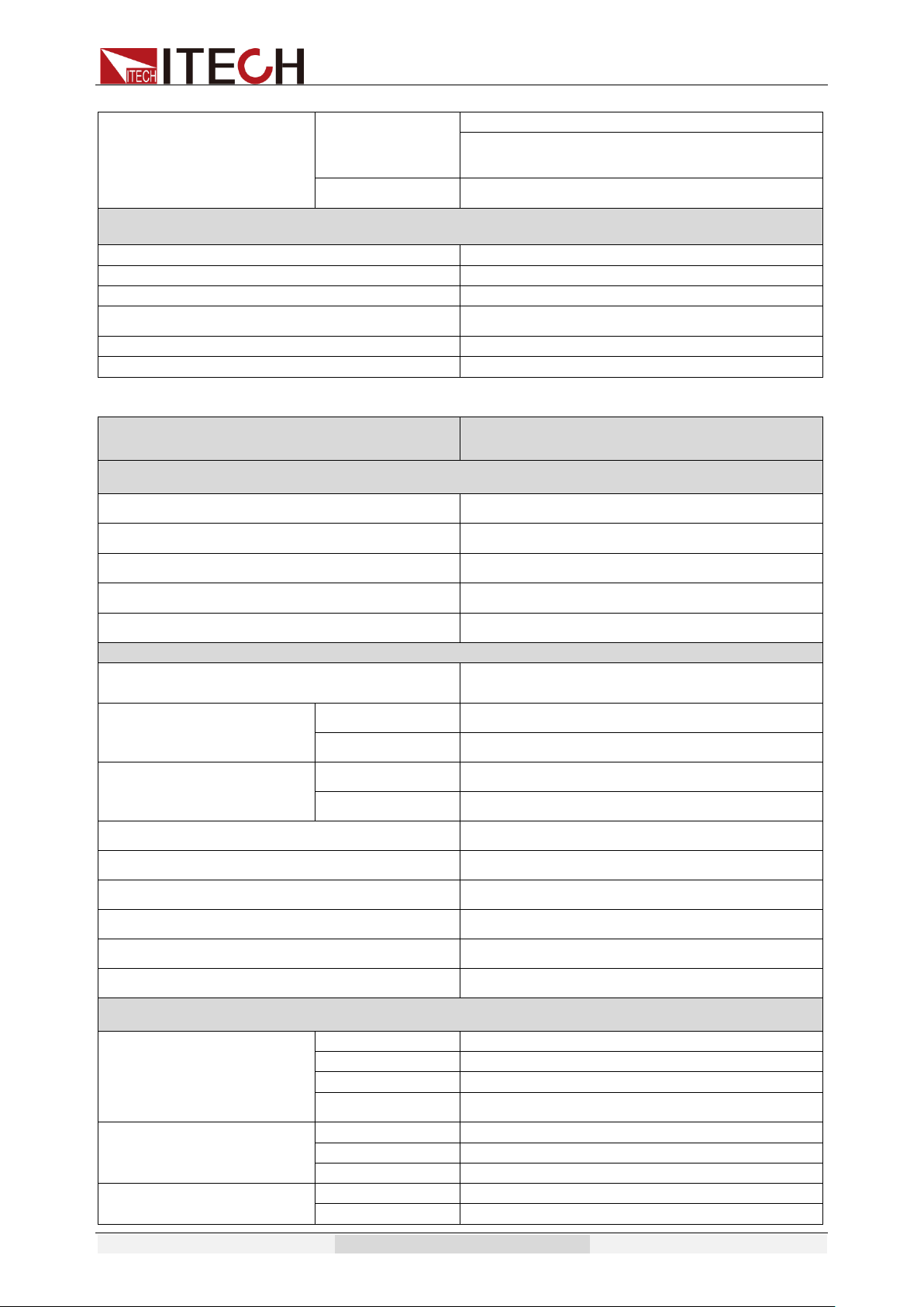
Specification
Copyright © Itech Electronic Co., Ltd. 52
M:±(0.2%+2W) (47HZ-65HZ)
H:±(0.2%+6W) (47HZ-65HZ)
Temp. coefficient
±(0.05% per degree from 25℃)
GENERAL
Memory
10 memories
Sync Output Signal
Output Signal 5V,BNC type
Interface(Option)
LAN,USB,RS232,GPIB
Operation Environment
0-40℃/20-80%RH
Dimension
19" 3U
Weight
37Kg
Model
IT7322H
INPUT
Phase
1
Voltage
220Vac±10% or 110Vac±10%
Frequency
47-63Hz
Max.Current
20A(220Vac) or 40A(110Vac)
Power Factor
0.7(typical)
AC OUTPUT
Max.Power
750VA
Max Current(rms)
0-250V
3A
0-500V
1.5A
Max Current(peak)
0-250V
9A
0-500V
4.5A
Phase
1Φ/3W
Total Harmonic Distortion(T.H.D)
≤1% at 45-500Hz (Resistive Load)
Crest Factor
≤3
Line Regulation
0.1% max for a ±10% line change
Load Regulation
≤0.5%FS(Resistive Load)
Response Time
<100uS
SETTING
Voltage
Range
0-500V High, 250/500V Auto
Resolution
0.1V
Accuracy
±(0.2%+1.2V)
Temp. coefficient
±(0.04% per degree from 25℃)
Frequency
Range
45-500Hz
Resolution
0.1Hz at 45-99.9Hz 1Hz at 100-500Hz
Accuracy
0.1Hz
Phase Angle
Range
0-360°
Resolution
0.1°
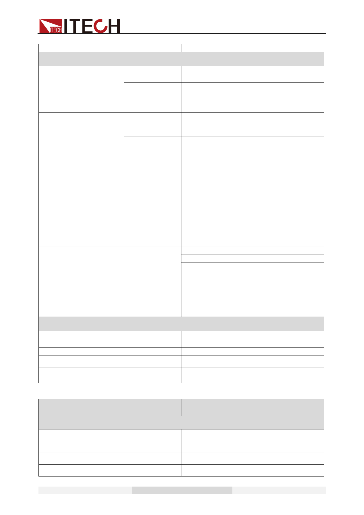
Specification
Copyright © Itech Electronic Co., Ltd. 53
Accuracy
±1°(45-65Hz)
MEASUREMENT
Voltage(rms)
Range
0-500V
Resolution
0.1V
Accuracy
±(0.2%+1.2V)
Temp. coefficient
±(0.04% per degree from 25℃)
Current(rms)
Range
L:120.0mA *
M:1.200A *
H:3.00A *
Resolution
L:0.1mA
M:1mA
H:10mA
Accuracy
L:±(0.2%+0.6mA)
M:±(0.2%+6mA)
H:±(0.2%+40mA)
Temp. coefficient
±(0.04% per degree from 25℃)
Current(peak)
Range
0-9A
Resolution
0.01A
Accuracy
±(1%+0.36A)
Temp. coefficient
±(0.05% per degree from 25℃)
Power
Resolution
L:0.01W
M:0.1W
H:1W
Accuracy
L:±(0.2%+0.2W) (47HZ-65HZ)
M:±(0.2%+2W) (47HZ-65HZ)
H:±(0.2%+6W) (47HZ-65HZ)
Temp. coefficient
±(0.05% per degree from 25℃)
GENERAL
Memory
10 memories
Sync Output Signal
Output Signal 5V,BNC type
Interface(Option)
LAN,USB,RS232,GPIB
Operation Environment
0-40℃/20-80%RH
Dimension
19" 3U
Weight
37Kg
Model
IT7324
INPUT
Phase
1
Voltage
220Vac±10% or 110Vac±10%
Frequency
47-63Hz
Max.Current
30A(220Vac) or 60A(110Vac)
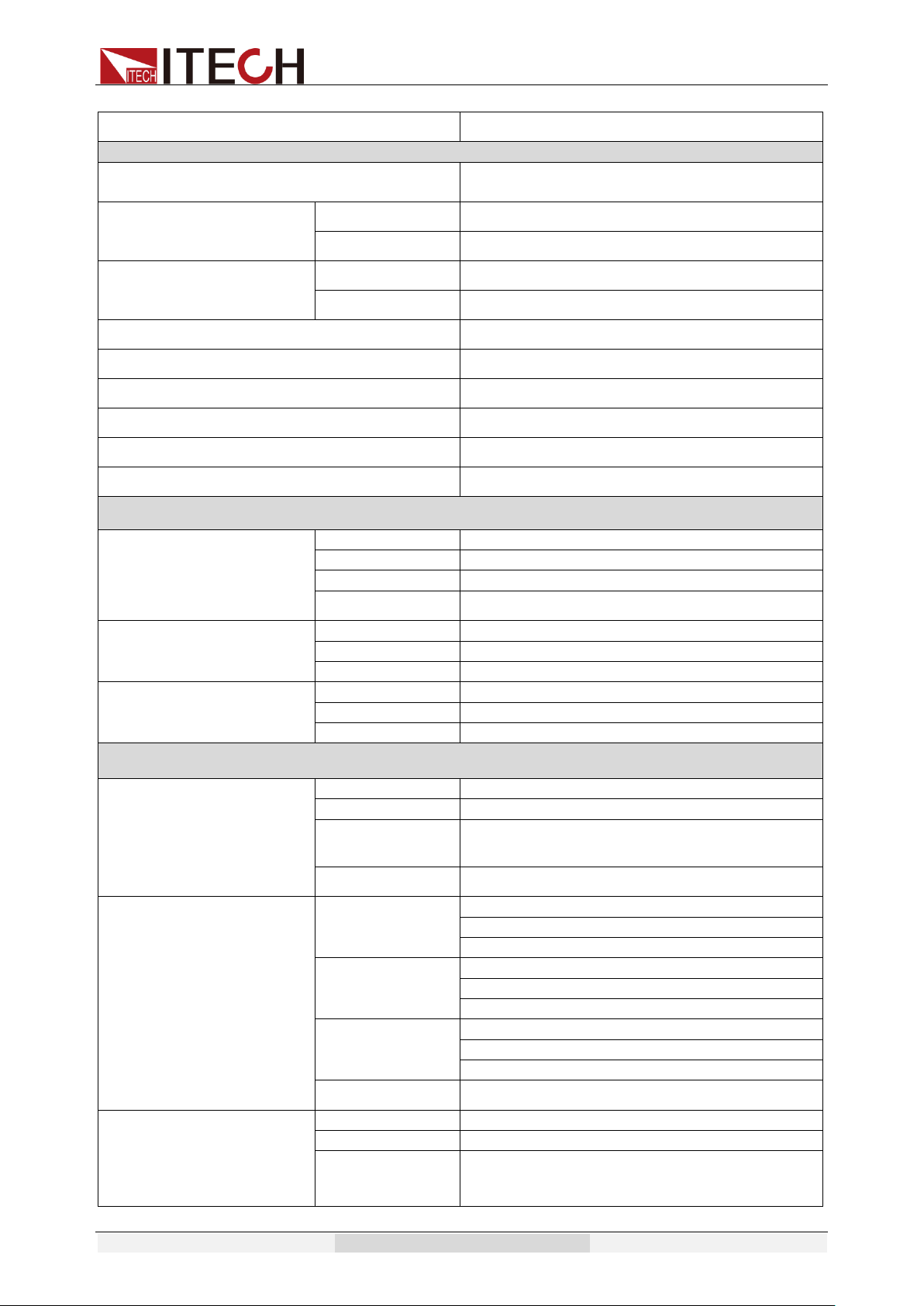
Specification
Copyright © Itech Electronic Co., Ltd. 54
Power Factor
0.7(typical)
AC OUTPUT
Max.Power
1500VA
Max Current(rms)
0-150V
12A
0-300V
6A
Max Current(peak)
0-150V
36A
0-300V
18A
Phase
1Φ/2W
Total Harmonic Distortion(T.H.D)
≤0.5% at 45-500Hz (Resistive Load)
Crest Factor
3
Line Regulation
0.1% max for a ±10% line change
Load Regulation
≤0.5%FS(Resistive Load)
Response Time
<100uS
SETTING
Voltage
Range
0-300V High, 150/300V Auto
Resolution
0.1V
Accuracy
±(0.2%+0.6V)
Temp. coefficient
±(0.04% per degree from 25℃)
Frequency
Range
45-500Hz
Resolution
0.1Hz at 45-99.9Hz 1Hz at 100-500Hz
Accuracy
0.1Hz
Phase Angle
Range
0-360°
Resolution
0.1°
Accuracy
±1°(45-65Hz)
MEASUREMENT
Voltage(rms)
Range
0-300V
Resolution
0.1V
Accuracy
±(0.2%+0.6V)
Temp. coefficient
±(0.04% per degree from 25℃)
Current(rms)
Range
L:120.0mA *
M:1.200A *
H:12.00A *
Resolution
L:0.1mA
M:1mA
H:10mA
Accuracy
L:±(0.2%+0.6mA)
M:±(0.2%+6mA)
H:±(0.2%+80mA)
Temp. coefficient
±(0.04% per degree from 25℃)
Current(peak)
Range
0-48A
Resolution
0.01A
Accuracy
±(1%+0.36A)
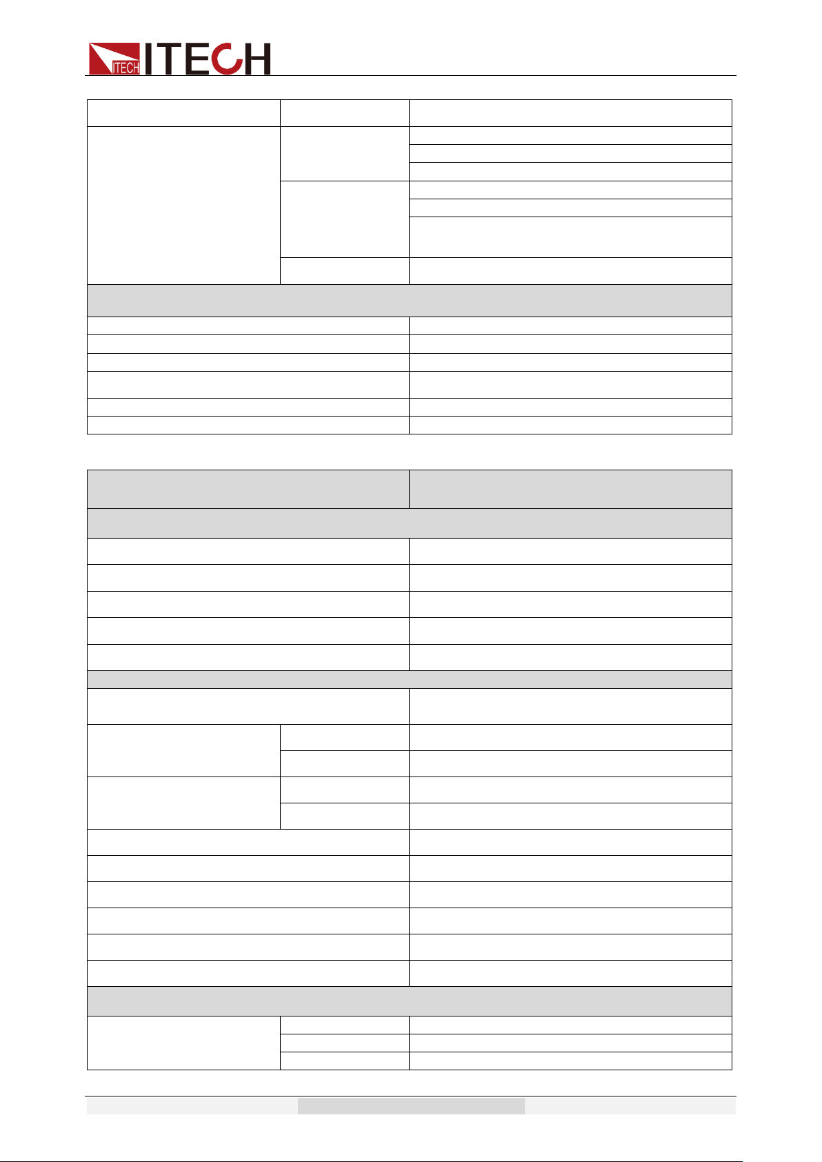
Specification
Copyright © Itech Electronic Co., Ltd. 55
Temp. coefficient
±(0.05% per degree from 25℃)
Power
Resolution
L:0.01W
M:0.1W
H:1W
Accuracy
L:±(0.2%+0.2W) (47HZ-65HZ)
M:±(0.2%+2W) (47HZ-65HZ)
H:±(0.2%+10W) (47HZ-65HZ)
Temp. coefficient
±(0.05% per degree from 25℃)
GENERAL
Memory
10 memories
Sync Output Signal
Output Signal 5V,BNC type
Interface(Option)
LAN,USB,RS232,GPIB
Operation Environment
0-40℃/20-80%RH
Dimension
19" 3U
Weight
48Kg
Model
IT7324H
INPUT
Phase
1
Voltage
220Vac±10% or 110Vac±10%
Frequency
47-63Hz
Max.Current
30A(220Vac) or 60A(110Vac)
Power Factor
0.7(typical)
AC OUTPUT
Max.Power
1500VA
Max Current(rms)
0-250V
6A
0-500V
3A
Max Current(peak)
0-250V
18A
0-500V
9A
Phase
1Φ/2W
Total Harmonic Distortion(T.H.D)
≤1% at 45-500Hz (Resistive Load)
Crest Factor
3
Line Regulation
0.1% max for a ±10% line change
Load Regulation
≤0.5%FS(Resistive Load)
Response Time
<100uS
SETTING
Voltage
Range
0-500V High, 250/500V Auto
Resolution
0.1V
Accuracy
±(0.2%+1.2V)
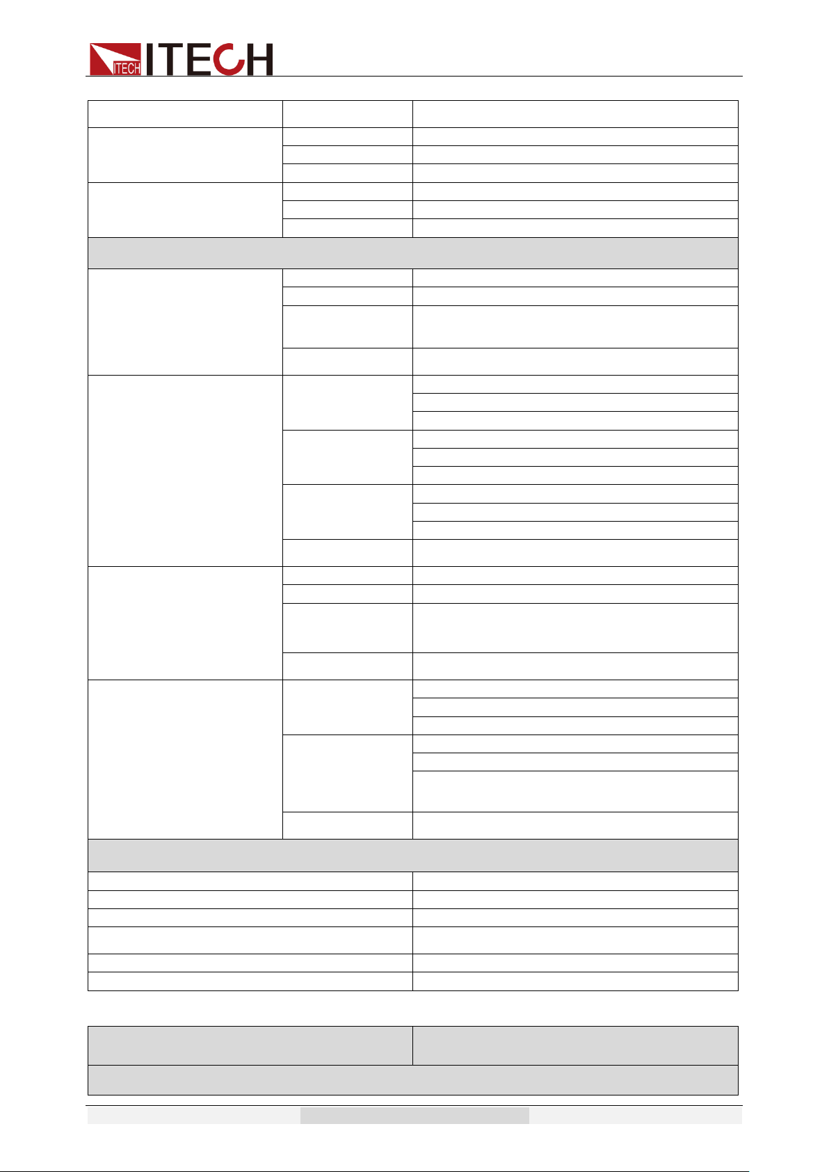
Specification
Copyright © Itech Electronic Co., Ltd. 56
Temp. coefficient
±(0.04% per degree from 25℃)
Frequency
Range
45-500Hz
Resolution
0.1Hz at 45-99.9Hz 1Hz at 100-500Hz
Accuracy
0.1Hz
Phase Angle
Range
0-360°
Resolution
0.1°
Accuracy
±1°(45-65Hz)
MEASUREMENT
Voltage(rms)
Range
0-500V
Resolution
0.1V
Accuracy
±(0.2%+1.2V)
Temp. coefficient
±(0.04% per degree from 25℃)
Current(rms)
Range
L:120.0mA *
M:1.200A *
H:6.00A *
Resolution
L:0.1mA
M:1mA
H:10mA
Accuracy
L:±(0.2%+0.6mA)
M:±(0.2%+6mA)
H:±(0.2%+60mA)
Temp. coefficient
±(0.04% per degree from 25℃)
Current(peak)
Range
0-24A
Resolution
0.01A
Accuracy
±(1%+0.36A)
Temp. coefficient
±(0.05% per degree from 25℃)
Power
Resolution
L:0.01W
M:0.1W
H:1W
Accuracy
L:±(0.2%+0.2W) (47HZ-65HZ)
M:±(0.2%+2W) (47HZ-65HZ)
H:±(0.2%+10W) (47HZ-65HZ)
Temp. coefficient
±(0.05% per degree from 25℃)
GENERAL
Memory
10 memories
Sync Output Signal
Output Signal 5V,BNC type
Interface(Option)
LAN,USB,RS232,GPIB
Operation Environment
0-40℃/20-80%RH
Dimension
19" 3U
Weight
37Kg
Model
IT7326
INPUT
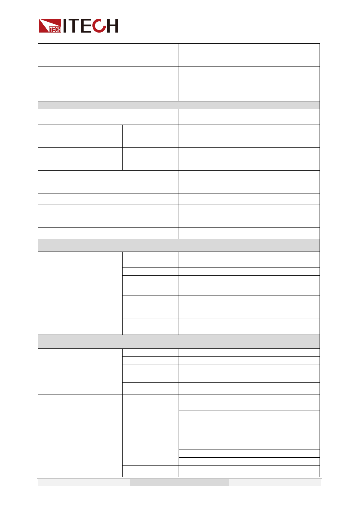
Specification
Copyright © Itech Electronic Co., Ltd. 57
Phase
1
Voltage
220Vac±10%
Frequency
47-63Hz
Max.Current
60A
Power Factor
0.7(typical)
AC OUTPUT
Max.Power
3000VA
Max Current(rms)
0-150V
24A
0-300V
12A
Max Current(peak)
0-150V
72A
0-300V
36A
Phase
1Φ/2W
Total Harmonic Distortion(T.H.D)
≤0.5% at 45-500Hz (Resistive Load)
Crest Factor
3
Line Regulation
0.1% max for a ±10% line change
Load Regulation
≤0.5%FS(Resistive Load)
Response Time
<100uS
SETTING
Voltage
Range
0-300V High, 150/300V Auto
Resolution
0.1V
Accuracy
±(0.2%+0.6V)
Temp. coefficient
±(0.04% per degree from 25℃)
Frequency
Range
45-500Hz
Resolution
0.1Hz at 45-99.9Hz 1Hz at 100-500Hz
Accuracy
0.1Hz
Phase Angle
Range
0-360°
Resolution
0.1°
Accuracy
±1°(45-65Hz)
MEASUREMENT
Voltage(rms)
Range
0-300V
Resolution
0.1V
Accuracy
±(0.2%+0.6V)
Temp. coefficient
±(0.04% per degree from 25℃)
Current(rms)
Range
L:120.0mA *
M:1.200A *
H:24.00A *
Resolution
L:0.1mA
M:1mA
H:10mA
Accuracy
L:±(0.2%+0.6mA)
M:±(0.2%+6mA)
H:±(0.2%+0.1A)
Temp. coefficient
±(0.04% per degree from 25℃)
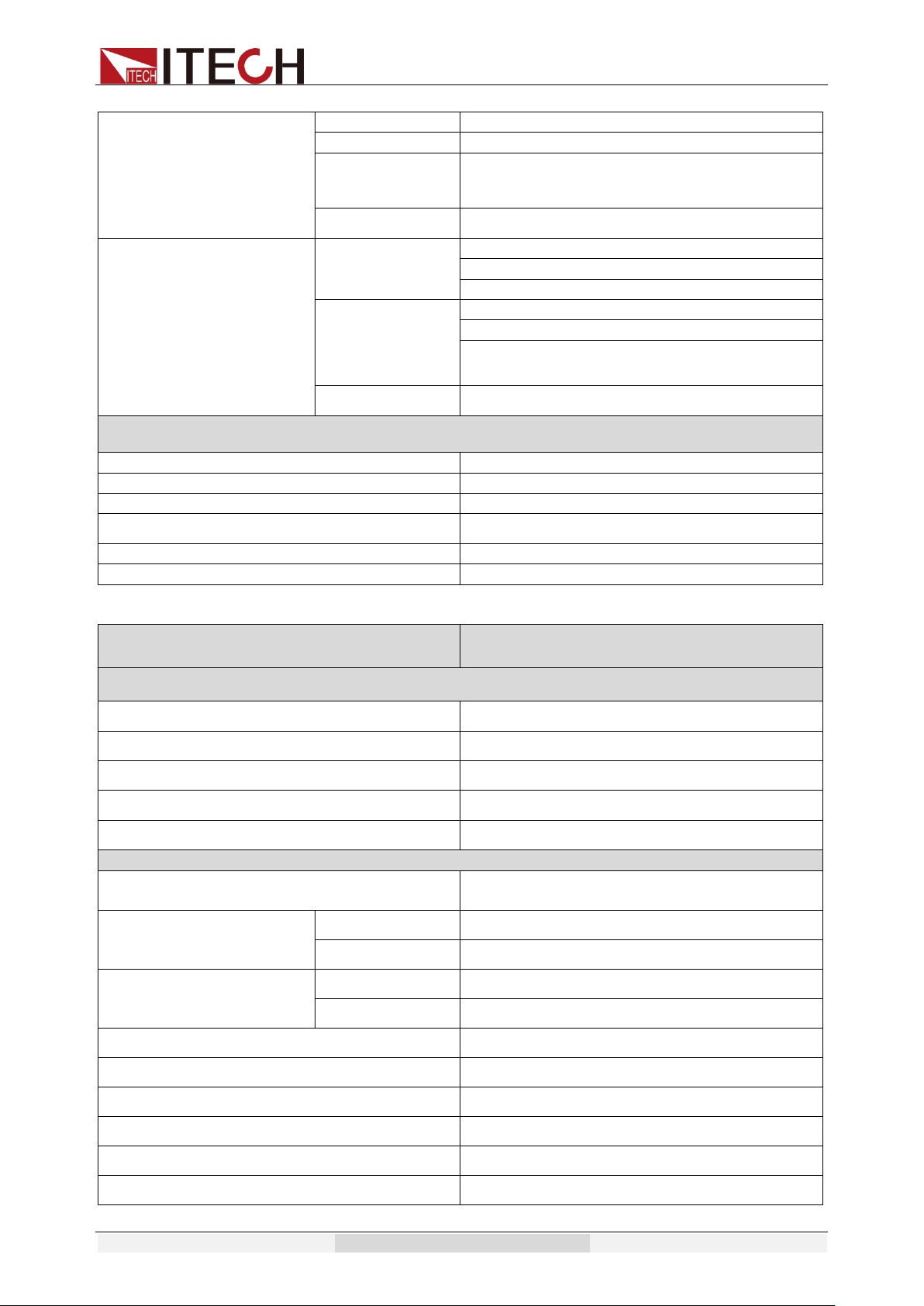
Specification
Copyright © Itech Electronic Co., Ltd. 58
Current(peak)
Range
0-96A
Resolution
0.01A
Accuracy
±(1%+0.36A)
Temp. coefficient
±(0.05% per degree from 25℃)
Power
Resolution
L:0.01W
M:0.1W
H:1W
Accuracy
L:±(0.2%+0.2W) (47HZ-65HZ)
M:±(0.2%+2W) (47HZ-65HZ)
H:±(0.2%+15W) (47HZ-65HZ)
Temp. coefficient
±(0.05% per degree from 25℃)
GENERAL
Memory
10 memories
Sync Output Signal
Output Signal 5V,BNC type
Interface(Option)
LAN,USB,RS232,GPIB
Operation Environment
0-40℃/20-80%RH
Dimension
19" 6U
Weight
103Kg
Model
IT7326H
INPUT
Phase
1
Voltage
220Vac±10%
Frequency
47-63Hz
Max.Current
60A
Power Factor
0.7(typical)
AC OUTPUT
Max.Power
3000VA
Max Current(rms)
0-250V
12A
0-500V
6A
Max Current(peak)
0-250V
36A
0-500V
18A
Phase
1Φ/2W
Total Harmonic Distortion(T.H.D)
≤1% at 45-500Hz (Resistive Load)
Crest Factor
3
Line Regulation
0.1% max for a ±10% line change
Load Regulation
≤0.5%FS(Resistive Load)
Response Time
<100uS
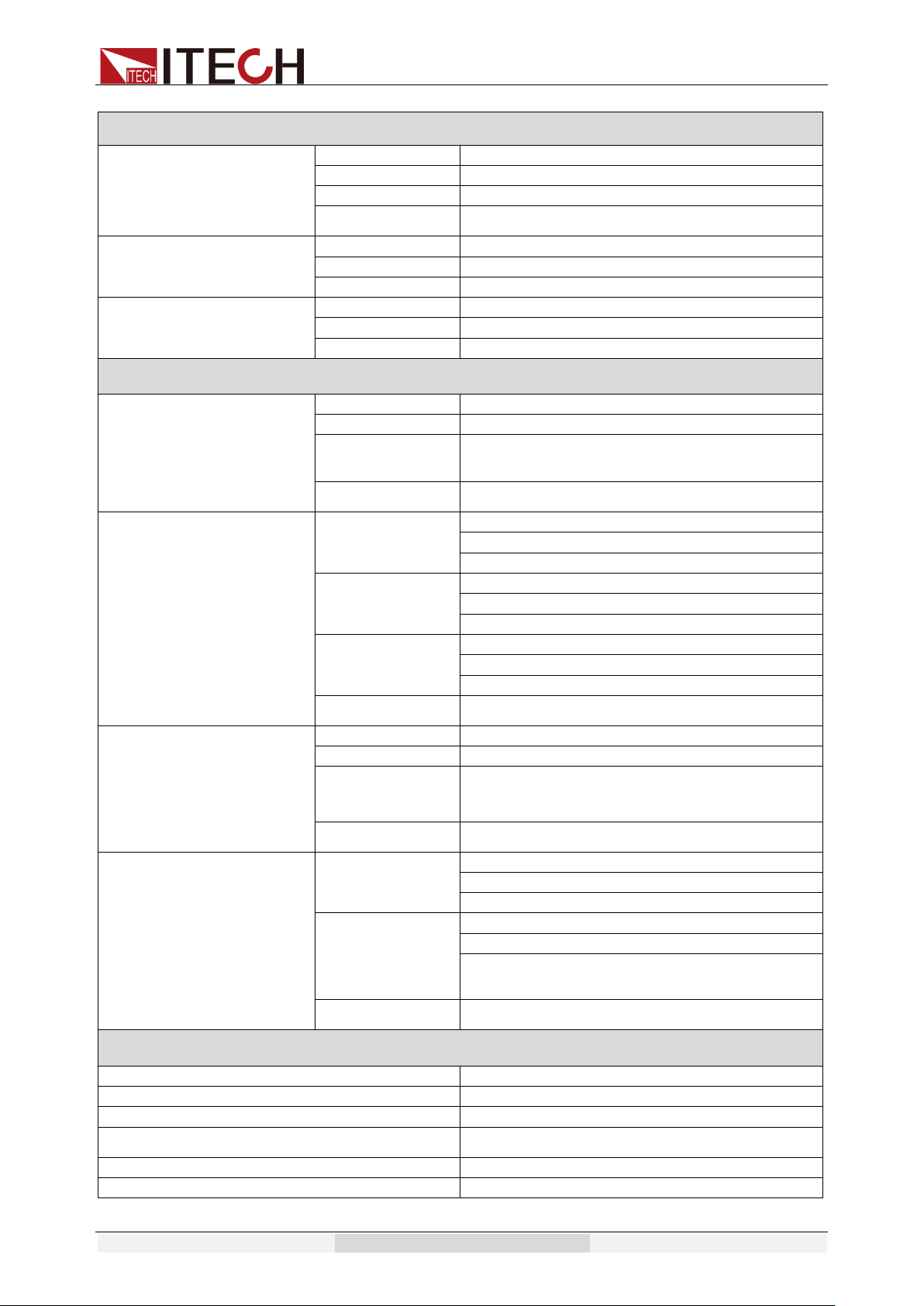
Specification
Copyright © Itech Electronic Co., Ltd. 59
SETTING
Voltage
Range
0-500V High, 250/500V Auto
Resolution
0.1V
Accuracy
±(0.2%+1.2V)
Temp. coefficient
±(0.04% per degree from 25℃)
Frequency
Range
45-500Hz
Resolution
0.1Hz at 45-99.9Hz 1Hz at 100-500Hz
Accuracy
0.1Hz
Phase Angle
Range
0-360°
Resolution
0.1°
Accuracy
±1°(45-65Hz)
MEASUREMENT
Voltage(rms)
Range
0-500V
Resolution
0.1V
Accuracy
±(0.2%+1.2V)
Temp. coefficient
±(0.04% per degree from 25℃)
Current(rms)
Range
L:120.0mA *
M:1.200A *
H:12.00A *
Resolution
L:0.1mA
M:1mA
H:10mA
Accuracy
L:±(0.2%+0.6mA)
M:±(0.2%+6mA)
H:±(0.2%+60mA)
Temp. coefficient
±(0.04% per degree from 25℃)
Current(peak)
Range
0-48A
Resolution
0.01A
Accuracy
±(1%+0.36A)
Temp. coefficient
±(0.05% per degree from 25℃)
Power
Resolution
L:0.01W
M:0.1W
H:1W
Accuracy
L:±(0.2%+0.2W) (47HZ-65HZ)
M:±(0.2%+2W) (47HZ-65HZ)
H:±(0.2%+10W) (47HZ-65HZ)
Temp. coefficient
±(0.05% per degree from 25℃)
GENERAL
Memory
10 memories
Sync Output Signal
Output Signal 5V,BNC type
Interface(Option)
LAN,USB,RS232,GPIB
Operation Environment
0-40℃/20-80%RH
Dimension
19" 6U
Weight
103Kg
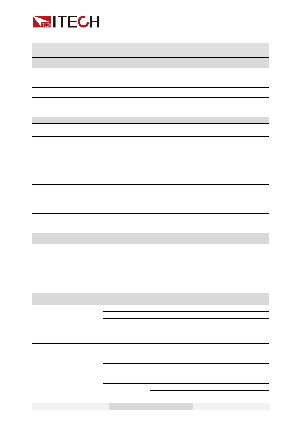
Specification
Copyright © Itech Electronic Co., Ltd. 60
Model
IT7322T
INPUT
Phase
3
Voltage
380Vac±10%(Y)
Frequency
47-63Hz
Max.Current
15A
Power Factor
0.7(typical)
AC OUTPUT
Max.Power
2250VA
Max Current(rms)
0-150V
6A
0-300V
3A
Max Current(peak)
0-150V
18A
0-300V
9A
Phase
3φ
Total Harmonic Distortion(T.H.D)
≤0.5% at 45-500Hz (Resistive Load)
Crest Factor
3
Line Regulation
0.1% max for a ±10% line change
Load Regulation
≤0.5%FS(Resistive Load)
Response Time
<100uS
SETTING
Voltage
Range
0-300V High, 150/300V Auto
Resolution
0.1V
Accuracy
±(0.2%+0.6V)
Temp. coefficient
±(0.04% per degree from 25℃)
Frequency
Range
45-500Hz
Resolution
0.1Hz at 45-99.9Hz 1Hz at 100-500Hz
Accuracy
0.1Hz
MEASUREMENT
Voltage(rms)
Range
0-300V
Resolution
0.1V
Accuracy
±(0.2%+0.6V)
Temp. coefficient
±(0.04% per degree from 25℃)
Current(rms)
Range
L:120.0mA *
M:1.200A *
H:6.00A *
Resolution
L:0.1mA
M:1mA
H:10mA
Accuracy
L:±(0.2%+0.6mA)
M:±(0.2%+6mA)
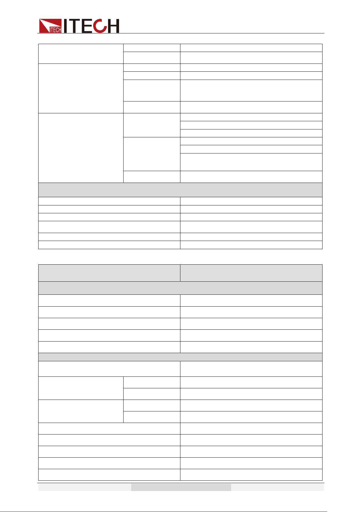
Specification
Copyright © Itech Electronic Co., Ltd. 61
H:±(0.2%+0.1A)
Temp. coefficient
±(0.04% per degree from 25℃)
Current(peak)
Range
0-18A
Resolution
0.01A
Accuracy
±(1%+0.36A)
Temp. coefficient
±(0.05% per degree from 25℃)
Power
Resolution
L:0.01W
M:0.1W
H:1W
Accuracy
L:±(0.2%+0.2W) (47HZ-65HZ)
M:±(0.2%+2W) (47HZ-65HZ)
H:±(0.2%+15W) (47HZ-65HZ)
Temp. coefficient
±(0.05% per degree from 25℃)
GENERAL
Memory
10 memories
Sync Output Signal
Output Signal 5V,BNC type
Interface(Option)
LAN,USB,RS232,GPIB
Operation Environment
0-40℃/20-80%RH
Dimension
15U
Weight
150Kg
Model
IT7322HT
INPUT
Phase
3
Voltage
380Vac±10%(Y)
Frequency
47-63Hz
Max.Current
15A
Power Factor
0.7(typical)
AC OUTPUT
Max.Power
2250VA
Max Current(rms)
0-250V
3A
0-500V
1.5A
Max Current(peak)
0-250V
9A
0-500V
4.5A
Phase
3φ
Total Harmonic Distortion(T.H.D)
≤1% at 45-500Hz (Resistive Load)
Crest Factor
3
Line Regulation
0.1% max for a ±10% line change
Load Regulation
≤0.5%FS(Resistive Load)

Specification
Copyright © Itech Electronic Co., Ltd. 62
Response Time
<100uS
SETTING
Voltage
Range
0-500V High, 250/500V Auto
Resolution
0.1V
Accuracy
±(0.2%+1.2V)
Temp. coefficient
±(0.04% per degree from 25℃)
Frequency
Range
45-500Hz
Resolution
0.1Hz at 45-99.9Hz 1Hz at 100-500Hz
Accuracy
0.1Hz
MEASUREMENT
Voltage(rms)
Range
0-500V
Resolution
0.1V
Accuracy
±(0.2%+1.2V)
Temp. coefficient
±(0.04% per degree from 25℃)
Current(rms)
Range
L:120.0mA *
M:1.200A *
H:3.00A *
Resolution
L:0.1mA
M:1mA
H:10mA
Accuracy
L:±(0.2%+0.6mA)
M:±(0.2%+6mA)
H:±(0.2%+60mA)
Temp. coefficient
±(0.04% per degree from 25℃)
Current(peak)
Range
0-9A
Resolution
0.01A
Accuracy
±(1%+0.36A)
Temp. coefficient
±(0.05% per degree from 25℃)
Power
Resolution
L:0.01W
M:0.1W
H:1W
Accuracy
L:±(0.2%+0.2W) (47HZ-65HZ)
M:±(0.2%+2W) (47HZ-65HZ)
H:±(0.2%+10W) (47HZ-65HZ)
Temp. coefficient
±(0.05% per degree from 25℃)
GENERAL
Memory
10 memories
Sync Output Signal
Output Signal 5V,BNC type
Interface(Option)
LAN,USB,RS232,GPIB
Operation Environment
0-40℃/20-80%RH
Dimension
15U
Weight
150Kg

Specification
Copyright © Itech Electronic Co., Ltd. 63
Model
IT7324T
INPUT
Phase
3
Voltage
380Vac±10%(Y)
Frequency
47-63Hz
Max.Current
30A
Power Factor
0.7(typical)
AC OUTPUT
Max.Power
4500VA
Max Current(rms)
0-150V
12A
0-300V
6A
Max Current(peak)
0-150V
36A
0-300V
18A
Phase
3φ
Total Harmonic Distortion(T.H.D)
≤0.5% at 45-500Hz (Resistive Load)
Crest Factor
3
Line Regulation
0.1% max for a ±10% line change
Load Regulation
≤0.5%FS(Resistive Load)
Response Time
<100uS
SETTING
Voltage
Range
0-300V High, 150/300V Auto
Resolution
0.1V
Accuracy
±(0.2%+0.6V)
Temp. coefficient
±(0.04% per degree from 25℃)
Frequency
Range
45-500Hz
Resolution
0.1Hz at 45-99.9Hz 1Hz at 100-500Hz
Accuracy
0.1Hz
MEASUREMENT
Voltage(rms)
Range
0-300V
Resolution
0.1V
Accuracy
±(0.2%+0.6V)
Temp. coefficient
±(0.04% per degree from 25℃)
Current(rms)
Range
L:120.0mA *
M:1.200A *
H:12.00A *
Resolution
L:0.1mA
M:1mA
H:10mA
Accuracy
L:±(0.2%+0.6mA)
M:±(0.2%+6mA)
H:±(0.2%+0.1A)

Specification
Copyright © Itech Electronic Co., Ltd. 64
Temp. coefficient
±(0.04% per degree from 25℃)
Current(peak)
Range
0-36A
Resolution
0.01A
Accuracy
±(1%+0.36A)
Temp. coefficient
±(0.05% per degree from 25℃)
Power
Resolution
L:0.01W
M:0.1W
H:1W
Accuracy
L:±(0.2%+0.2W) (47HZ-65HZ)
M:±(0.2%+2W) (47HZ-65HZ)
H:±(0.2%+15W) (47HZ-65HZ)
Temp. coefficient
±(0.05% per degree from 25℃)
GENERAL
Memory
10 memories
Sync Output Signal
Output Signal 5V,BNC type
Interface(Option)
LAN,USB,RS232,GPIB
Operation Environment
0-40℃/20-80%RH
Dimension
24U
Weight
250Kg
Model
IT7324HT
INPUT
Phase
3
Voltage
380Vac±10%(Y)
Frequency
47-63Hz
Max.Current
30A
Power Factor
0.7(typical)
AC OUTPUT
Max.Power
4500VA
Max Current(rms)
0-250V
6A
0-500V
3A
Max Current(peak)
0-250V
18A
0-500V
9A
Phase
3φ
Total Harmonic Distortion(T.H.D)
≤1% at 45-500Hz (Resistive Load)
Crest Factor
3
Line Regulation
0.1% max for a ±10% line change
Load Regulation
≤0.5%FS(Resistive Load)

Specification
Copyright © Itech Electronic Co., Ltd. 65
Response Time
<100uS
SETTING
Voltage
Range
0-500V High, 250/500V Auto
Resolution
0.1V
Accuracy
±(0.2%+1.2V)
Temp. coefficient
±(0.04% per degree from 25℃)
Frequency
Range
45-500Hz
Resolution
0.1Hz at 45-99.9Hz 1Hz at 100-500Hz
Accuracy
0.1Hz
MEASUREMENT
Voltage(rms)
Range
0-500V
Resolution
0.1V
Accuracy
±(0.2%+1.2V)
Temp. coefficient
±(0.04% per degree from 25℃)
Current(rms)
Range
L:120.0mA *
M:1.200A *
H:6.00A *
Resolution
L:0.1mA
M:1mA
H:10mA
Accuracy
L:±(0.2%+0.6mA)
M:±(0.2%+6mA)
H:±(0.2%+60mA)
Temp. coefficient
±(0.04% per degree from 25℃)
Current(peak)
Range
0-18A
Resolution
0.01A
Accuracy
±(1%+0.36A)
Temp. coefficient
±(0.05% per degree from 25℃)
Power
Resolution
L:0.01W
M:0.1W
H:1W
Accuracy
L:±(0.2%+0.2W) (47HZ-65HZ)
M:±(0.2%+2W) (47HZ-65HZ)
H:±(0.2%+10W) (47HZ-65HZ)
Temp. coefficient
±(0.05% per degree from 25℃)
GENERAL
Memory
10 memories
Sync Output Signal
Output Signal 5V,BNC type
Interface(Option)
LAN,USB,RS232,GPIB
Operation Environment
0-40℃/20-80%RH
Dimension
24U
Weight
250Kg
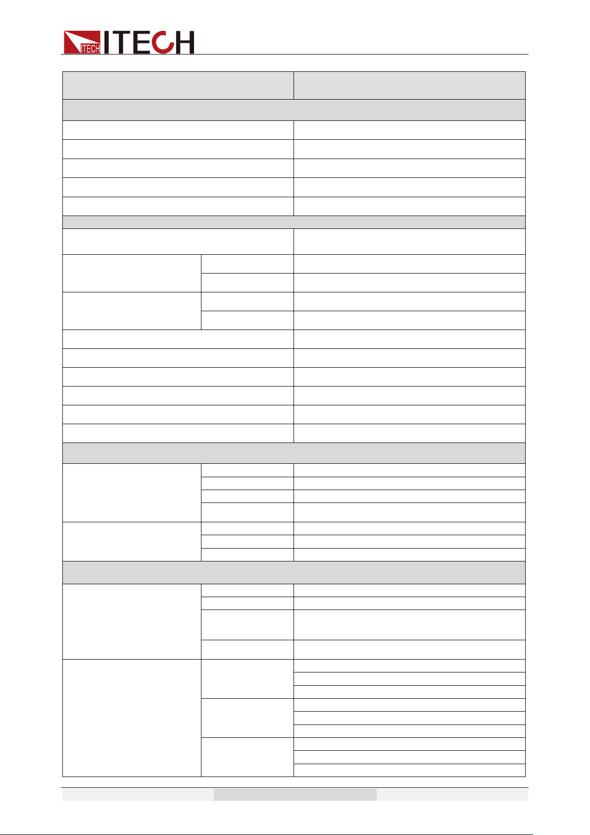
Specification
Copyright © Itech Electronic Co., Ltd. 66
Model
IT7326T
INPUT
Phase
3
Voltage
380Vac±10%(Y)
Frequency
47-63Hz
Max.Current
60A
Power Factor
0.7(typical)
AC OUTPUT
Max.Power
9000VA
Max Current(rms)
0-150V
24A
0-300V
12A
Max Current(peak)
0-150V
72A
0-300V
36A
Phase
3φ
Total Harmonic Distortion(T.H.D)
≤0.5% at 45-500Hz (Resistive Load)
Crest Factor
3
Line Regulation
0.1% max for a ±10% line change
Load Regulation
≤0.5%FS(Resistive Load)
Response Time
<100uS
SETTING
Voltage
Range
0-300V High, 150/300V Auto
Resolution
0.1V
Accuracy
±(0.2%+0.6V)
Temp. coefficient
±(0.04% per degree from 25℃)
Frequency
Range
45-500Hz
Resolution
0.1Hz at 45-99.9Hz 1Hz at 100-500Hz
Accuracy
0.1Hz
MEASUREMENT
Voltage(rms)
Range
0-300V
Resolution
0.1V
Accuracy
±(0.2%+0.6V)
Temp. coefficient
±(0.04% per degree from 25℃)
Current(rms)
Range
L:120.0mA *
M:1.200A *
H:24.00A *
Resolution
L:0.1mA
M:1mA
H:10mA
Accuracy
L:±(0.2%+0.6mA)
M:±(0.2%+6mA)
H:±(0.2%+0.1A)
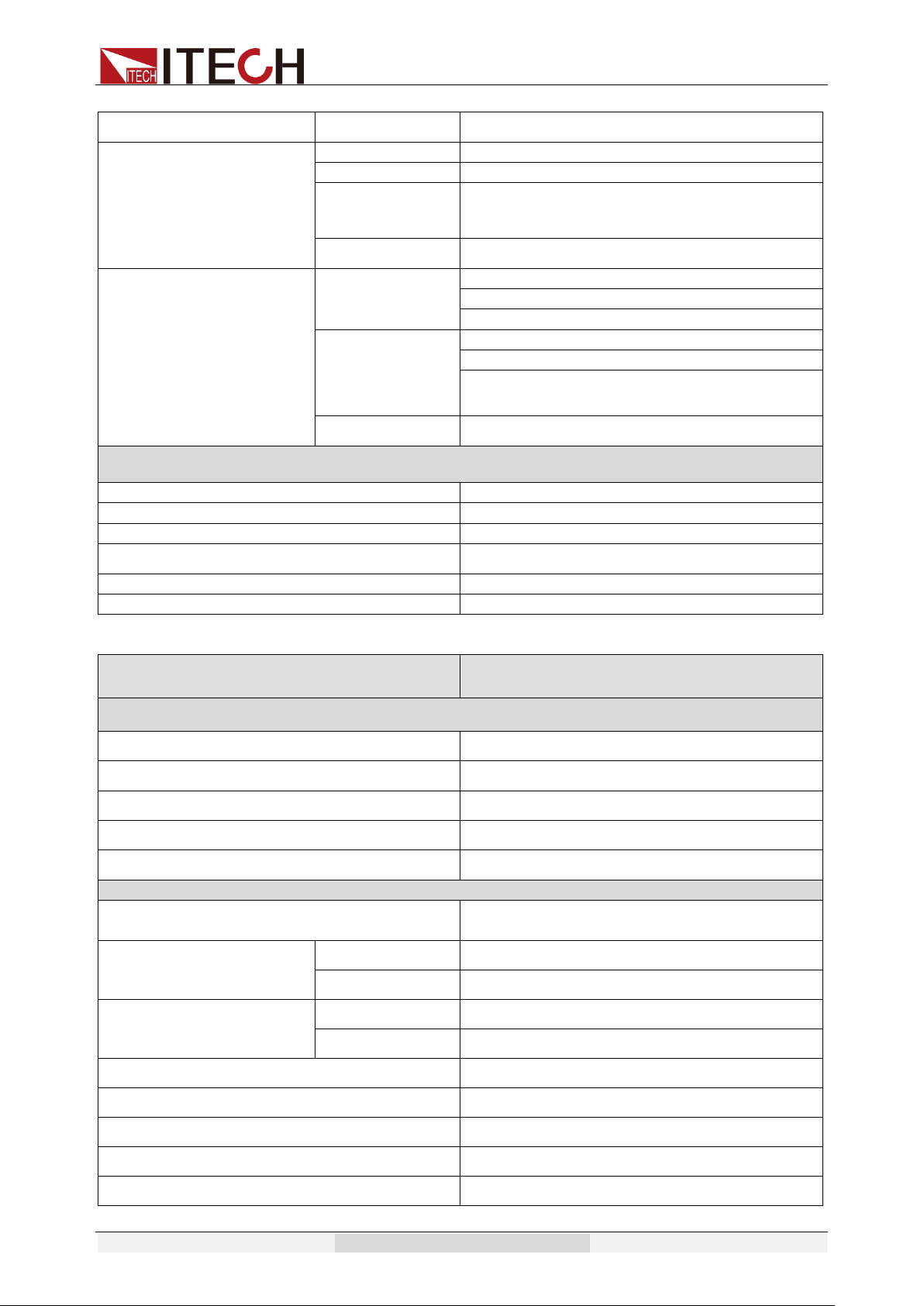
Specification
Copyright © Itech Electronic Co., Ltd. 67
Temp. coefficient
±(0.04% per degree from 25℃)
Current(peak)
Range
0-72A
Resolution
0.01A
Accuracy
±(1%+0.36A)
Temp. coefficient
±(0.05% per degree from 25℃)
Power
Resolution
L:0.01W
M:0.1W
H:1W
Accuracy
L:±(0.2%+0.2W) (47HZ-65HZ)
M:±(0.2%+2W) (47HZ-65HZ)
H:±(0.2%+15W) (47HZ-65HZ)
Temp. coefficient
±(0.05% per degree from 25℃)
GENERAL
Memory
10 memories
Sync Output Signal
Output Signal 5V,BNC type
Interface(Option)
LAN,USB,RS232,GPIB
Operation Environment
0-40℃/20-80%RH
Dimension
24U
Weight
400Kg
Model
IT7326HT
INPUT
Phase
3
Voltage
380Vac±10%(Y)
Frequency
47-63Hz
Max.Current
60A
Power Factor
0.7(typical)
AC OUTPUT
Max.Power
9000VA
Max Current(rms)
0-250V
12A
0-500V
6A
Max Current(peak)
0-250V
36A
0-500V
18A
Phase
3φ
Total Harmonic Distortion(T.H.D)
≤1% at 45-500Hz (Resistive Load)
Crest Factor
3
Line Regulation
0.1% max for a ±10% line change
Load Regulation
≤0.5%FS(Resistive Load)
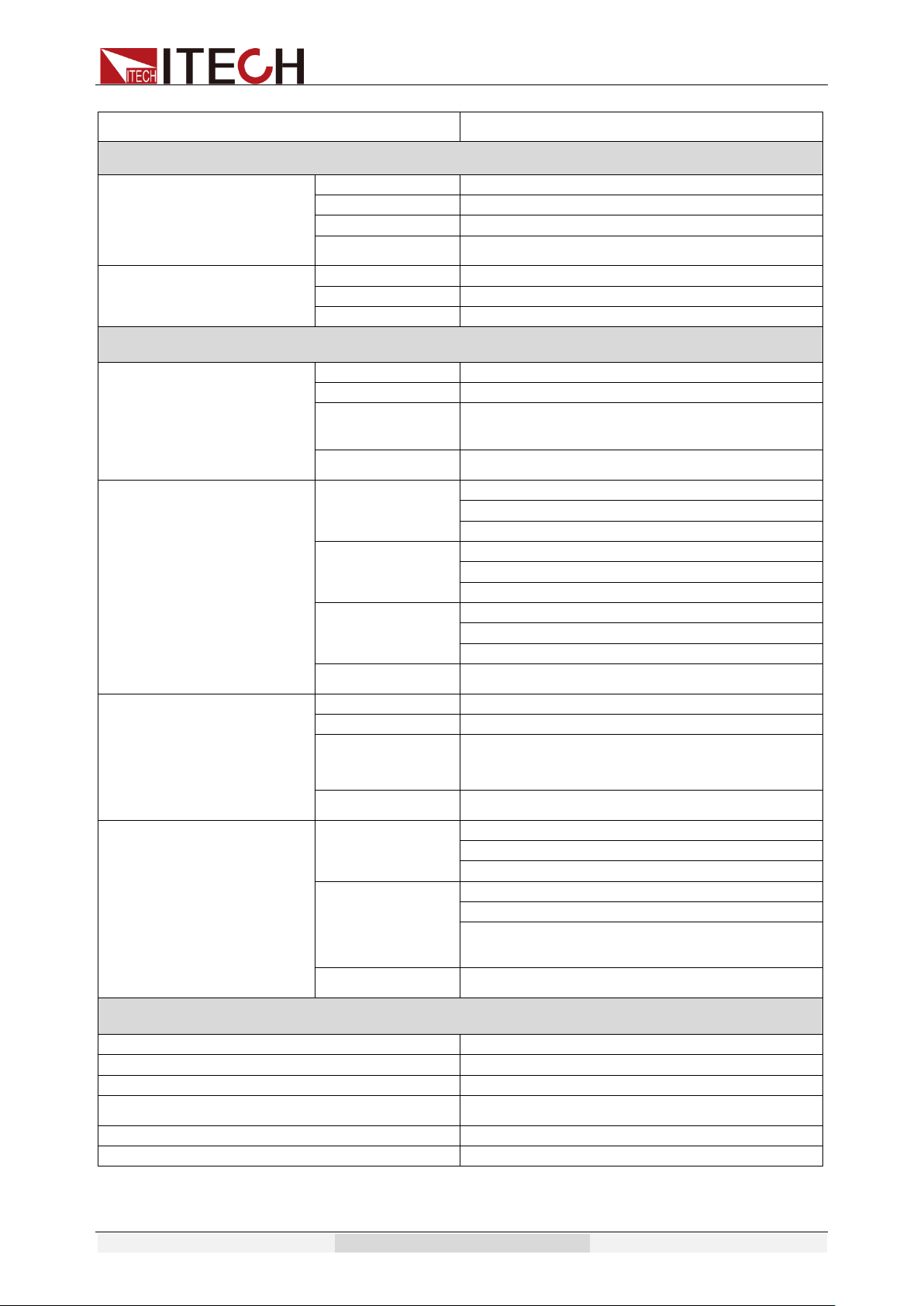
Specification
Copyright © Itech Electronic Co., Ltd. 68
Response Time
<100uS
SETTING
Voltage
Range
0-500V High, 250/500V Auto
Resolution
0.1V
Accuracy
±(0.2%+1.2V)
Temp. coefficient
±(0.04% per degree from 25℃)
Frequency
Range
45-500Hz
Resolution
0.1Hz at 45-99.9Hz 1Hz at 100-500Hz
Accuracy
0.1Hz
MEASUREMENT
Voltage(rms)
Range
0-500V
Resolution
0.1V
Accuracy
±(0.2%+0.6V)
Temp. coefficient
±(0.04% per degree from 25℃)
Current(rms)
Range
L:120.0mA *
M:1.200A *
H:12.00A *
Resolution
L:0.1mA
M:1mA
H:10mA
Accuracy
L:±(0.2%+0.6mA)
M:±(0.2%+6mA)
H:±(0.2%+0.1A)
Temp. coefficient
±(0.04% per degree from 25℃)
Current(peak)
Range
0-36A
Resolution
0.01A
Accuracy
±(1%+0.36A)
Temp. coefficient
±(0.05% per degree from 25℃)
Power
Resolution
L:0.01W
M:0.1W
H:1W
Accuracy
L:±(0.2%+0.2W) (47HZ-65HZ)
M:±(0.2%+2W) (47HZ-65HZ)
H:±(0.2%+15W) (47HZ-65HZ)
Temp. coefficient
±(0.05% per degree from 25℃)
GENERAL
Memory
10 memories
Sync Output Signal
Output Signal 5V,BNC type
Interface(Option)
LAN,USB,RS232,GPIB
Operation Environment
0-40℃/20-80%RH
Dimension
24U
Weight
400Kg
*Description about the switch of current range:

Specification
Copyright © Itech Electronic Co., Ltd. 69
When Ipeak > 300% (Full rms), the current switch from low range to high range (L to M, M to H).
When Ipeak < 20% (Full rms), the current switch from high range to low range (M to L).
When Ipeak < 80% (3Arms), the current switch from high range to Middle range (H to M).
The above specifications may be subject to change without prior notice.
4.2 Supplemental Characteristics
⚫ State storage capacity
10sets
⚫ Recommended calibration frequency
once a year
⚫ Cooling style
fans
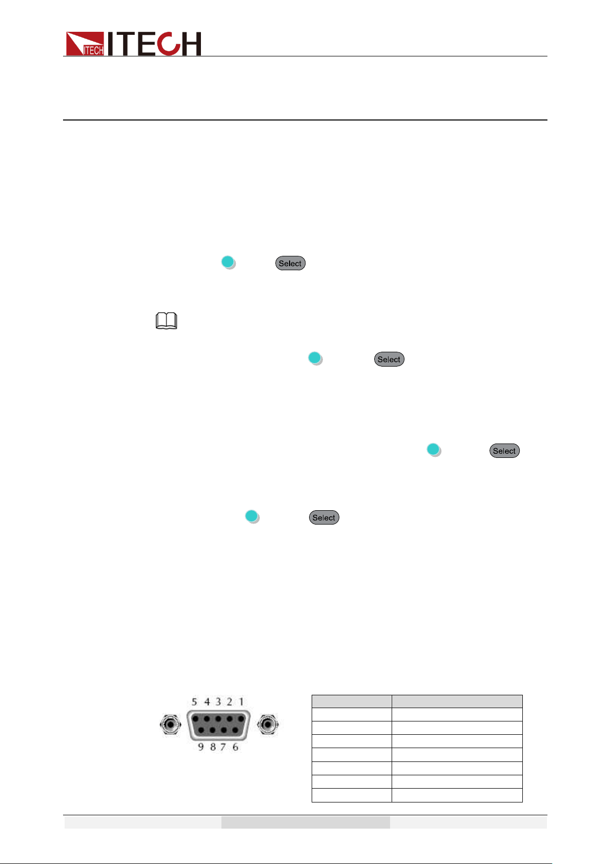
Remote Control
Copyright © Itech Electronic Co., Ltd. 70
Chapter5 Remote Control
IT7300 series AC source (except IT7321) has four standard
communication interfaces: LAN RS232, USB, and GPIB. IT7321 has
standard communication interface: LAN/USB/RS232. You can choose
any one of them to communicate with PC.
5.1 RS232 Interface
There is a DB9 connector at the rear of the power supply, when connect to
computer, you need to select a cable with COM port on both side; To active you
need to press (Shift)+ (Menu) button to enable the settings in menu to
be the same with the PC communication configuration. You could do the
secondary development with all SCPI commands.
Note
The RS232 settings must match the settings in front panel system information.
If any change, please press (Shift) + (Menu) key to modify the
menu: SYST SET\COMM.
RS232 data format
RS232 data is a 10-bit word with one start bit and one stop bit. The number of
start bit is not programmable. Stop bit is selectable between 1&2.Besides, you
can set the parity bit in the menu using the front panel (Shift) + key.
Parity options are stored in a non-volatile memory.
Baudrate
The front panel (Shift) + (Menu) button allows the user to set
baud rate which is stored in the non-volatile memory: 4800,9600,19200
38400, 57600,115200
RS-232 connection
Adopt the RS232 cable with DB-9 interface because the serial port of RS232
can be connected with that of the controller (e.g. PC). The modulating cable of
the air-conditioner is not recommended. The pins of plug are shown as the
following table.
If your computer is provided with a RS232 interface with DB-25 plug, a cable
and an adapter with DB-25 plug (one end) and DB-9 plug (the other end) are
required (not the modulating cable of the air-conditioner)
RS-232 plug pins
Pin number
Description
1
No connection
2
TXD, transfer data
3
RXD, receive data
4
No connection
5
GND, ground
6
No connection
7
CTS, clear transfer

Remote Control
Copyright © Itech Electronic Co., Ltd. 71
8
RTS, ready to transfer
9
No connection
RS-232 Troubleshooting
In case of connection failure of RS232, perform following check:
⚫ Check if the computer and power supply are provided with same
Baud rate, parity check bit, data bit and flow control. The power
supply shall be configured with one start bit (fixed) and one or two
stop bits.
⚫ Just as described in the RS232 connector, appropriate interface
cable or adapter shall be adopted. Notes: even if the cable is
equipped with right plug, internal wiring may be incorrect.
⚫ The interface cable must be connected to the right serial port (COM1
and COM2) of the computer.
Communication Setup
Please ensure the PC and power supply has the same configuration in the
following items.
Baudrate: 9600(4800, 9600, 19200, 38400, 57600, 115200). You could enter
the system menu to set the baudrate.
Data bit: 8
Stop bit: 1
Parity bit: (none, even, odd)
EVEN 8 data bits have even parity
ODD 8 data bits have odd parity
NONE 8 data bits have no parity
Native machine address: (0 ~31, factory default is 0)
Start Bit
8 Data Bits
Parity=None
Stop Bit
5.2 USB Interface
Use a cable with two USB ports to connect power supply and PC. You can
program through USB interface to achieve all functions of power supply.
The functions of USB488 interface are as follows:
⚫ Interface is 488.2 USB488 interface
⚫ Receive the following request: REN_CONTROL, GO_TO_LOCAL, and
LOCAL_LOCKOUT
⚫ When the interface receives MsgID = TRIGGER USBTMC command, it will
transmit the TRIGGER command to the function layer.
The functions of power supply’s USB488 are as follows:
⚫ receive all SCPI commands
⚫ device is SR1 enabled
⚫ device is RL1 enabled
⚫ device is DT1 enabled

Remote Control
Copyright © Itech Electronic Co., Ltd. 72
5.3 LAN Interface
Press (Shift) + (Menu) on the front panel together to access the
menu. Select LAN in the Communication from System and then configure
Gateway, IP, Mask and SocketPort in the LAN option.
Connect the LAN interface of power supply to the computer with a reticle
(crossed).
5.4 GPIB Interface
Use a IEEE488 bus to connect GPIB interfaces of power supply and PC.
Please ensure that the screws have been screwed down in order to have a full
connection. Then press + (Menu) to enter the system menu, and
then select the Communication to set the GPIB address. The address range of
power supply is 0 to 30. After you set the address, please press
button to confirm, GPIB address is saved in nonvolatile memory.
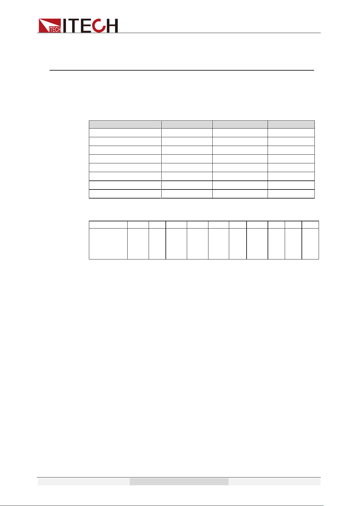
Appendix
Copyright © Itech Electronic Co., Ltd. 73
Appendix
Specifications of Red and Black Test Lines
ITECH provides you with optional red and black test lines, the user can choose
the company's test line for testing. For specifications of ITECH test lines and
maximum current values, refer to the table below.
Model
Specification
Cross section
Length
IT-E301/10A
10A
-
1m
IT-E301/30A
30A
6mm
2
1.2m
IT-E301/30A
30A
6mm
2
2m
IT-E301/60A
60A
20mm
2
1.5m
IT-E301/120A
120A
50mm
2
2m
IT-E301/240A
240A
70mm
2
1m
IT-E301/240A
240A
70mm
2
2m
IT-E301/360A
360A
95mm
2
2m
For maximum current of AWG copper wire, refer to table blow.
AWG
10
12
14
16
18
20
22
24
26
28
The
Maximum
current
value( A)
40
25
20
13
10
7
5
3.5
2.5
1.7
Note: AWG ( American Wire Gage), it means X wire ( marked on the wire). The
table above lists current capacity of single wire at working temperature of 30°C.
For reference only.