
Programmable AC Power
Source
IT-M7700 Series User Manual
Model: IT-M7700 Series
Version: V1.1/5,2020
Notices
© Itech Electronic, Co.,
Ltd. 2020
No part of this manual
may be reproduced in any
form or by any means (in-
cluding electronic storage
and retrieval or translation
into a foreign language)
without prior permission
and written consent from
Itech Electronic, Co., Ltd.
as governed by interna-
tional copyright laws.
Manual Part Number
Warranty
The materials contained in this docu-
ment are provided “as is”, and is sub-
ject to change, without prior notice, in
future editions. Further, to the maxi-
mum extent permitted by applicable
laws, ITECH disclaims all warrants, ei-
ther express or implied, with regard to
this manual and any information con-
tained herein, including but not limited
to the implied warranties of merchant-
ability and fitness for a particular pur-
pose. ITECH shall not be held liable
for errors or for incidental or indirect
Safety Notices
A CAUTION sign denotes
a hazard. It calls attention
to an operating procedure
or practice that, if not cor-
rectly performed or ad-
hered to, could result in
damage to the product or
loss of important data. Do
not proceed beyond a
CAUTION sign until the in-
dicated conditions are
fully understood and met.
damages in connection with the fur-
nishing, use or application of this
document or of any information con-
Trademarks
Pentium is U.S. registered
trademarks of Intel
Corporation.
Microsoft, Visual Studio,
Windows and MS Win-
dows are registered
trademarks of Microsoft
Corporation in the United
States and/or other coun-
tries and regions.
tained herein. Should ITECH and the
user enter into a separate written
agreement with warranty terms cover-
ing the materials in this document that
conflict with these terms, the warranty
terms in the separate agreement shall
prevail.
Technology Licenses
The hardware and/or software de-
scribed herein are furnished under a li-
cense and may be used or copied only
in accordance with the terms of such
license.
Restricted Rights Legend
Restricted permissions of the U.S.
government. Permissions for software
and technical data which are author-
ized to the U.S. Government only in-
clude those for custom provision to
end users. ITECH follows FAR 12.211
(technical data), 12.212 (computer
software). DFARS 252.227-7015
(technical data–commercial products)
for national defense and DFARS
227.7202-3 (permissions for commer-
cial computer software or computer
software documents) while providing
the customized business licenses of
software and technical data.
A WARNING sign denotes
a hazard. It calls attention
to an operating procedure
or practice that, if not cor-
rectly performed or ad-
hered to, could result in
personal injury or death.
Do not proceed beyond a
WARNING sign until the
indicated conditions are
fully understood and met.
A NOTE sign denotes im-
portant hint. It calls atten-
tion to tips or
supplementary informa-
tion that is essential for
users to refer to.

IT-M7700 Series User Manual
Copyright © Itech Electronic Co., Ltd.
I
Quality Certification and Assurance
We certify that series instrument meets all the published specifications at time
of shipment from the factory.
Warranty
ITECH warrants that the product will be free from defects in material and work-
manship under normal use for a period of one (1) year from the date of delivery
(except those described in the Limitation of Warranty below).
For warranty service or repair, the product must be returned to a service center
designated by ITECH.
•
The product returned to ITECH for warranty service must be shipped PRE-
PAID. And ITECH will pay for return of the product to customer.
•
If the product is returned to ITECH for warranty service from overseas, all
the freights, duties and other taxes shall be on the account of customer.
Limitation of Warranty
This Warranty will be rendered invalid in case of the following:
•
Damage caused by circuit installed by customer or using customer own
products or accessories;
•
Modified or repaired by customer without authorization;
•
Damage caused by circuit installed by customer or not operating our prod-
ucts under designated environment;
•
The product model or serial number is altered, deleted, removed or made il-
legible by customer;
•
Damaged as a result of accidents, including but not limited to lightning, mois-
ture, fire, improper use or negligence.
IT-M7700 Series User Manual
Copyright © Itech Electronic Co., Ltd.
II
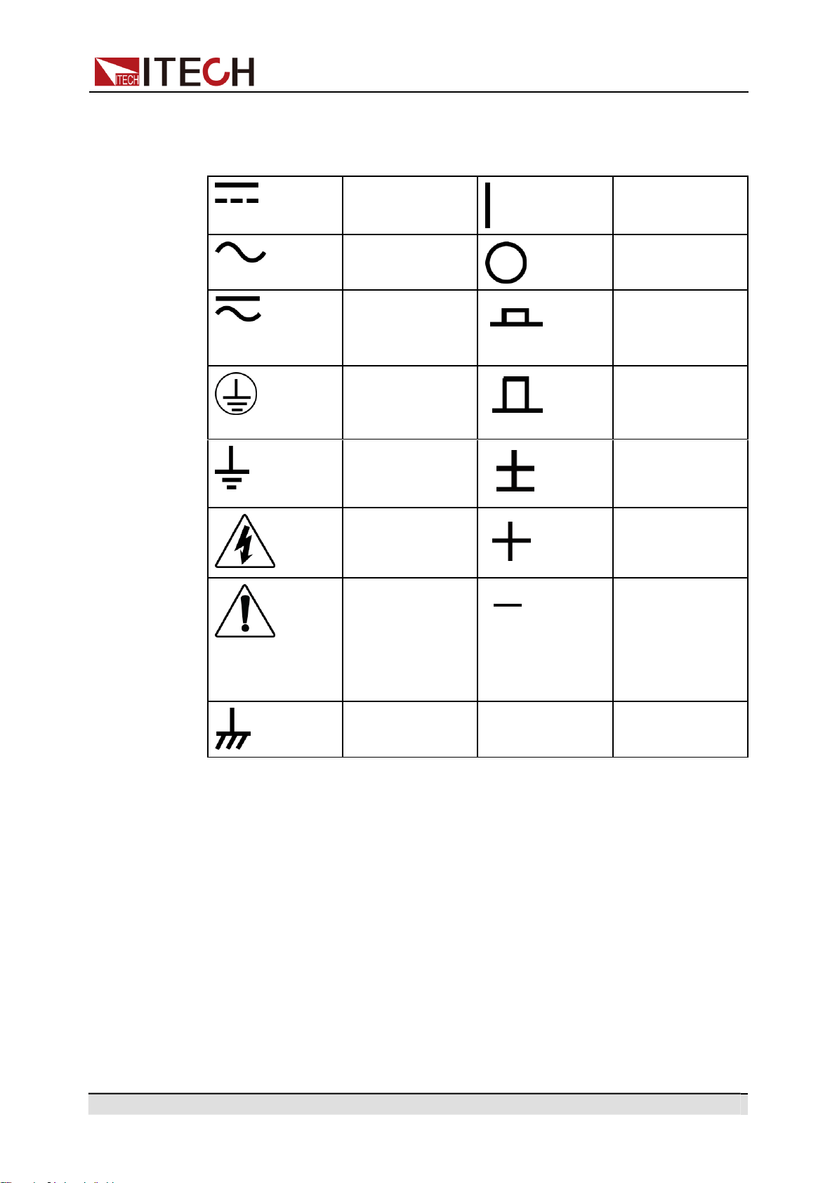
Safety Symbols
Direct current
ON ( power)
Alternating
current
OFF ( power)
Both direct and
alternating
current
Power-on state
Chassis (earth
ground) symbol.
Power-off state
Earth ( ground)
terminal
Reference
terminal
Caution
Positive terminal
Warning ( refer to
this manual for
specific Warning
or Caution
information)
Negative terminal
A chassis
terminal
-
-
Safety Precautions
The following safety precautions must be observed during all phases of opera-
tion of this instrument. Failure to comply with these precautions or specific warn-
ings elsewhere in this manual will constitute a default under safety standards of
design, manufacture and intended use of the instrument. ITECH assumes no li-
ability for the customer’s failure to comply with these precautions.

Copyright © Itech Electronic Co., Ltd.
III
IT-M7700 Series User Manual
•
Do not use the instrument if it is damaged. Before operation, check
the casing to see whether it cracks. Do not operate the instrument
in the presence of inflammable gasses, vapors or dusts.
•
The instrument is provided with a power cord during delivery and
should be connected to a socket with a protective earth terminal, a
junction box or a three-phase distribution box. Before operation, be
sure that the instrument is well grounded.
•
Please always use the provided cable to connect the instrument.
•
Check all marks on the instrument before connecting the instru-
ment to power supply.
•
Ensure the voltage fluctuation of mains supply is less than 10% of
the working voltage range in order to reduce risks of fire and elec-
tric shock.
•
Do not install alternative parts on the instrument or perform any un-
authorized modification.
•
Do not use the instrument if the detachable cover is removed or
loosen.
•
To prevent the possibility of accidental injuries, be sure to use the
power adapter supplied by the manufacturer only.
•
We do not accept responsibility for any direct or indirect financial
damage or loss of profit that might occur when using the
instrument.
•
This instrument is used for industrial purposes, do not apply this
product to IT power supply system.
•
Never use the instrument with a life-support system or any other
equipment subject to safety requirements.

Copyright © Itech Electronic Co., Ltd.
IV
IT-M7700 Series User Manual
•
SHOCK HAZARD Ground the Instrument. This product is provided
with a protective earth terminal. To minimize shock hazard, the in-
strument must be connected to the AC mains through a grounded
power cable, with the ground wire firmly connected to an electrical
ground (safety ground) at the power outlet or distribution box. Any
interruption of the protective (grounding) conductor or disconnec-
tion of the protective earth terminal will cause a potential shock
hazard that could result in injury or death.
•
Before applying power, verify that all safety precautions are taken.
All connections must be made with the instrument turned off, and
must be performed by qualified personnel who are aware of the
hazards involved. Improper actions can cause fatal injury as well as
equipment damage.
•
SHOCK HAZARD, LETHAL VOLTAGES This product can output the
dangerous voltage that can cause personal injury, and the operator
must always be protected from electric shock. Ensure that the out-
put electrodes are either insulated or covered using the safety cov-
ers provided, so that no accidental contact with lethal voltages can
occur.
•
Never touch cables or connections immediately after turning off the
instrument. Verify that there is no dangerous voltage on the electro-
des or sense terminals before touching them.
•
After using the device, turn off the power switch of the device be-
fore unplugging the power cord or disassembling the terminals. Do
not touch the cable or the terminal immediately. Depending on the
model, the dangerous voltage at the plug or terminal is maintained
for 10 seconds after the device is switched off. Make sure that there
is no dangerous voltage before touching them.
•
Failure to use the instrument as directed by the manufacturer may
render its protective features void.
•
Always clean the casing with a dry cloth. Do not clean the internals.
•
Make sure the vent hole is always unblocked.
Environmental Conditions
The instrument is designed for indoor use and an area with low condensation.
The table below shows the general environmental requirements for the
instrument.
Copyright © Itech Electronic Co., Ltd.
V
IT-M7700 Series User Manual
Environmental Conditions Requirements
Operating temperature 0 40
Operating humidity 20% 80% (non-condensation)
Storage temperature -20 70
Altitude Operating up to 2,000 meters
Installation category II
Pollution degree Pollution degree 2
In order to ensure the accuracy of measurement, it is recommended to oper-
ate the instrument half an hour after start-up.
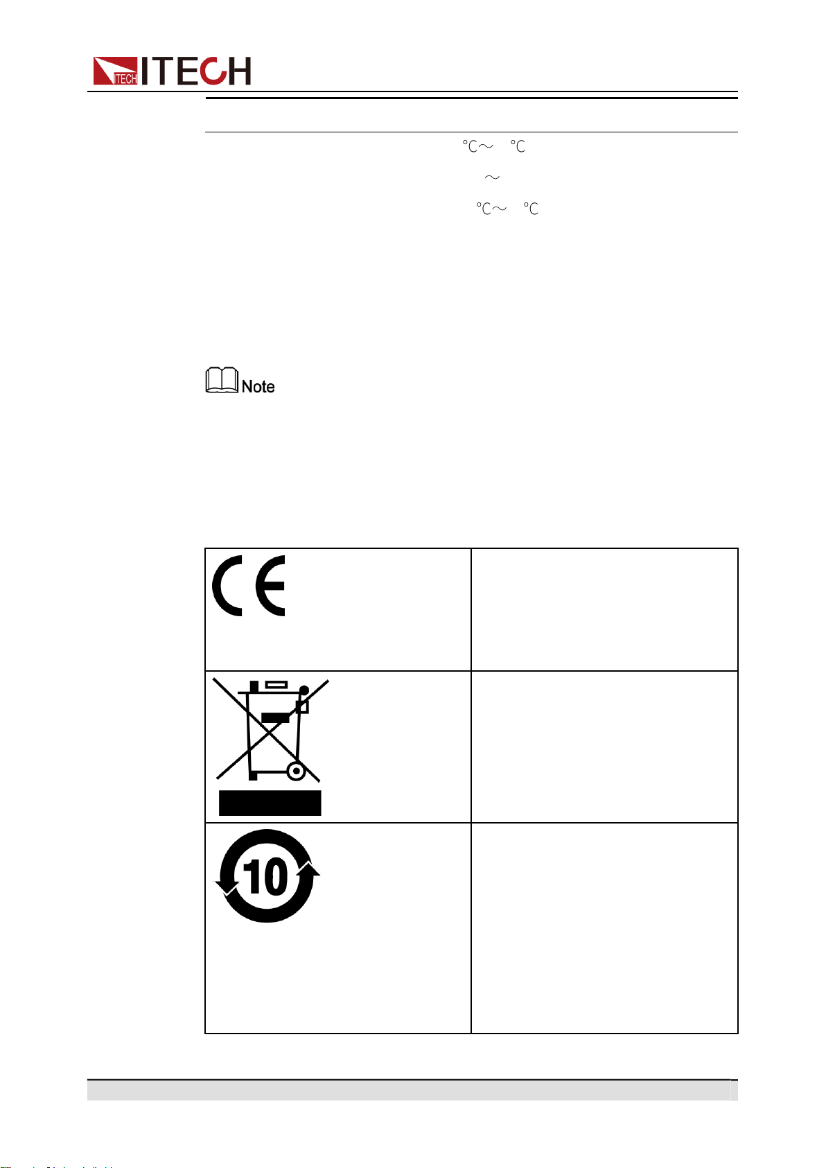
Regulation Tag
The CE tag shows that the product
complies with the provisions of all rel-
evant European laws (if the year is
shown, it indicates that the year when
the design is approved).
This instrument complies with the
WEEE directive (2002/96/EC) tag re-
quirements. This attached product
tag shows that the electrical/elec-
tronic product cannot be discarded in
household waste.
This symbol indicates that no danger
will happen or toxic substances will
not leak or cause damage in normal
use within the specified period. The
service life of the product is 10 years.
The product can be used safely within
the environmental protection period;
otherwise, the product should be put
into the recycling system.

Copyright © Itech Electronic Co., Ltd.
VI
IT-M7700 Series User Manual
Waste Electrical and Electronic Equipment
(WEEE) Directive
Waste electrical and electronic equip-
ment (WEEE) directive, 2002/96/EC
The product complies with tag re-
quirements of the WEEE directive
(2002/96/EC). This tag indicates that
the electronic equipment cannot be
disposed of as ordinary household
waste. Product Category
According to the equipment classifi-
cation in Annex I of the WEEE direc-
tive, this instrument belongs to the
“Monitoring” product.
If you want to return the unnecessary
instrument, please contact the near-
est sales office of ITECH.

Copyright © Itech Electronic Co., Ltd.
VII
IT-M7700 Series User Manual
Compliance Information
Complies with the essential requirements of the following applicable European
Directives, and carries the CE marking accordingly:
•
Electromagnetic Compatibility (EMC) Directive 2014/30/EU
•
Low-Voltage Directive (Safety) 2014/35/EU
Conforms with the following product standards:
EMC Standard
IEC 61326-1:2012/ EN 61326-1:2013 ¹²³
Reference Standards
CISPR 11:2015+A1:2016 Ed 6.1
IEC 61000-3-2: 2018 RLV
IEC 61000-3-3: 2013+A1:2017
IEC 61000-4-2:2008
IEC 61000-4-3 2006+A1:2007+A2:2010/ EN 61000-4-3 A1:2008+A2:2010
IEC 61000-4-4:2012
IEC 61000-4-5:2014+A1:2017
IEC 61000-4-6:2013+cor1:2015
IEC 61000-4-11:2004+A1:2017
1.
The product is intended for use in non-residential/non-domestic environments. Use of the
product in residential/domestic environments may cause electromagnetic interference.
2.
Connection of the instrument to a test object may produce radiations beyond the specified
limit.
3.
Use high-performance shielded interface cable to ensure conformity with the EMC standards
listed above.
Safety Standard
IEC 61010-1:2010+A1:2016

Copyright © Itech Electronic Co., Ltd.
VIII
IT-M7700 Series User Manual
Content
Quality Certification and Assurance ............................................................................... I
Warranty ........................................................................................................................ I
Limitation of Warranty .................................................................................................... I
Safety Symbols ............................................................................................................. II
Safety Precautions. ....................................................................................................... II
Environmental Conditions. .......................................................................................... IV
Regulation Tag ............................................................................................................ V
Waste Electrical and Electronic Equipment (WEEE) Directive ..................................... VI
Compliance Information ............................................................................................. VII
1
Quick Reference ............................................................................................................. 1
1.1
Brief Introduction .................................................................................................. 1
1.2
Front Panel at a Glance ........................................................................................ 2
1.3
Front Panel Keys at a Glance ............................................................................... 3
1.4
Rear Panel at a Glance ......................................................................................... 5
1.5
Front Panel Display at a Glance ............................................................................ 6
1.6
Configuration Menu at a Glance ............................................................................ 9
1.7
System Menu at a Glance ................................................................................... 10
1.8
Optional Accessories .......................................................................................... 14
2
Inspection and Installation ............................................................................................ 16
2.1
Verifying the Shipment ........................................................................................ 16
2.2
Instrument Size Introduction ............................................................................... 17
2.3
Rack Mounting ................................................................................................... 17
2.4
Connecting the Power Cord ................................................................................ 18
2.5
Connecting the Device Under Test (DUT) ........................................................... 20
2.6
Connecting the Interface ..................................................................................... 22
2.6.1
USB Interface ........................................................................................... 23
2.6.2
GPIB Interface .......................................................................................... 24
2.6.3
LAN Interface ........................................................................................... 25
2.6.4
RS-232 Interface ...................................................................................... 31
2.6.5
CAN Interface ........................................................................................... 33
3
Getting Started ............................................................................................................. 35
3.1
Power-on the Instrument .................................................................................... 35
3.2
Applying DC Output ............................................................................................ 37
3.3
Applying Waveform Output ................................................................................. 38
4
Operation and Application ............................................................................................ 41
4.1
Select the Output Mode ...................................................................................... 41
4.2
Set the AC Output ............................................................................................... 42
4.2.1
Set the AC Voltage ................................................................................... 42
4.2.2
Set the AC Frequency ............................................................................... 43
4.2.3
Set the AC Phase Angle ........................................................................... 43
4.2.4
Select the Output Waveform ..................................................................... 44
4.3
Set the DC Output .............................................................................................. 45
4.3.1
Set the DC Voltage ................................................................................... 45
4.3.2
Set the DC Voltage Rise Time .................................................................. 45
4.4
Set the Over-current Protection Point ................................................................. 46
4.5
Turning the Output On and Off ............................................................................ 47
4.6
Executing Measurement ..................................................................................... 47
4.6.1
Measurement Functions ........................................................................... 47
4.7
Function Operation ............................................................................................. 48
4.7.1
List Function ............................................................................................. 48
4.7.2
Dimmer Function ...................................................................................... 50
4.7.3
Surge/Trap Function ................................................................................. 51
4.8
Protection Function ............................................................................................. 53
4.8.1
Set the Over-Voltage Protection (rms) ...................................................... 53
4.8.2
Set the Over-Voltage Protection (peak) ..................................................... 54

Copyright © Itech Electronic Co., Ltd.
IX
IT-M7700 Series User Manual
4.8.3
Set the Under-Voltage Protection (rms) .................................................... 55
4.8.4
Set the Over-Current Protection (rms) ....................................................... 56
4.8.5
Set the Over-Current Protection (peak) ..................................................... 57
4.8.6
Set the Over-Power Protection ................................................................. 58
4.8.7
Set the Current Limiting Protection ........................................................... 59
4.8.8
Set the Sense Check Protection ............................................................... 59
4.8.9
Limiting the Setting Value Range .............................................................. 60
4.9
System-Related Operations. ............................................................................... 60
4.9.1
Switch Local/Remote Mode ...................................................................... 60
4.9.2
Save and Recall Operations ..................................................................... 61
4.9.3
Key Lock Function .................................................................................... 61
4.9.4
Set the Beeper Status ............................................................................... 62
4.9.5
Set the Power-on State ............................................................................. 62
4.9.6
Restore the as-shipped settings ................................................................ 63
4.9.7
View the System Information .................................................................... 65
4.9.8
Set the Relay Control. ............................................................................... 66
4.10
External Analog Quantity Function (Option) ...................................................... 66
4.10.1
Definition of Analog Interface .................................................................. 66
4.10.2
Enable/Disable Analog Control ............................................................... 69
4.10.3
Analog Quantity Control .......................................................................... 70
5
Multi-units operation ..................................................................................................... 75
5.1
Series Operation ................................................................................................ 75
5.2
Three-phase Operation....................................................................................... 78
6
Routine Maintenance .................................................................................................... 83
6.1
Instrument Self-Test. .......................................................................................... 83
6.2
Cleaning and Maintenance ................................................................................. 83
6.3
Prompt Information Reference ............................................................................ 84
6.4
Contact of ITECH Engineers ............................................................................... 85
6.5
Return for Repair. ............................................................................................... 87
7
Technical Specification ................................................................................................. 88
7.1 IT-M7721 ............................................................................................................ 88
7.2 IT-M7721L .......................................................................................................... 90
7.3 IT-M7722 ............................................................................................................ 92
7.4 IT-M7722L .......................................................................................................... 94
A
Appendix ...................................................................................................................... 97
A.1
Specifications of Red and Black Test Lines ........................................................ 97
A.2
Built -in Waveforms ............................................................................................ 98

Quick Reference
Copyright © Itech Electronic Co., Ltd.
1
1 Quick Reference
This chapter briefly introduces the front panel, rear panel, keyboard button func-
tions and front panel display functions of this series instrument to ensure a quick
understanding of the appearance, structure and key usage features of the in-
strument before operating the instrument. This chapter does not introduces
each operating characteristics in detail. It is just a quick reference guide to help
you quickly learn the operating characteristics of the instrument.
Brief Introduction
Front Panel at a Glance
Front Panel Keys at a Glance
Rear Panel at a Glance
Front Panel Display at a Glance
Configuration Menu at a Glance
System Menu at a Glance
Optional Accessories
1.1
Brief Introduction
ITECH newly-launched IT-M7700 High Performance Programmable AC Power
Supply combines intelligence and flexibility, breaks through the huge defects of
the traditional AC power source, reduces the size to only 1⁄2 1U, maximizes
space utilization. Built-in power meter and arbitrary waveform generator make it
convenient to simulate various arbitrary waveform outputs. IT-M7700 is de-
signed with advanced technologies of programmable AC and DC power sup-
plies, and can be widely used in multiple fields such as power energy products,
home appliances, industrial electronics, avionics, military and IEC standards
testing.
Features:
•
1⁄2 1U compact design, increased space utilization
•
AC, DC, AC + DC output modes, DC voltage offset simulation in AC + DC
mode
•
Built-in AC power meter with powerful functions
•
Built-in abundant waveform database, including 30 harmonic distortion
waveforms *1
•
List mode, simulate civil AC working condition, realize instantaneous power
interruption simulation function *1*2
•
Arbitrary waveform output function, user can customize waveforms *1
•
Harmonic analysis function *1
Quick Reference
Copyright © Itech Electronic Co., Ltd.
2
•
Harmonic simulation function *1
•
Surge/Trap function *1
•
Front and rear edge Dimmer phase dimming function Settable output wave-
form start/stop phase angle *1
•
Settable output waveform start/stop phase angle
•
Higher voltage available by two units in series connection *1*3
•
Three phase output available by three units Y-type external
connections *1*3
•
Optional interfaces include RS232, CAN, LAN, GPIB, USB_TMC,USB_
VCP, external analog, IO. Flexible and cost effective
•
With professional software, set up programs comply with multinational se-
curity regulations and test conditions, to complete military, civil aviation elec-
tronics and IEC related standards testing *1*4
*1 IT-M7721L/IT-M7722L do not support this function.
*2 Realize by PC software.
*3 IT-M7723/IT-M7724 do not support this function.
*4 Coming soon
Model Selection Table for IT-M7700 Series:
Model
Power(AC/DC)
Voltage
Current
Frequency
Height
IT-M7721
300 VA/300 W
300 V
3 A
45~1000 Hz
1/2 1U
IT-M7721L
300 VA/300 W
300 V
3 A
45~100 Hz
1/2 1U
IT-M7722
600 VA/600 W
300 V
6A
45~1000 Hz
1/2 1U
IT-M7722L
600 VA/600 W
300 V
6A
45~100 Hz
1/2 1U
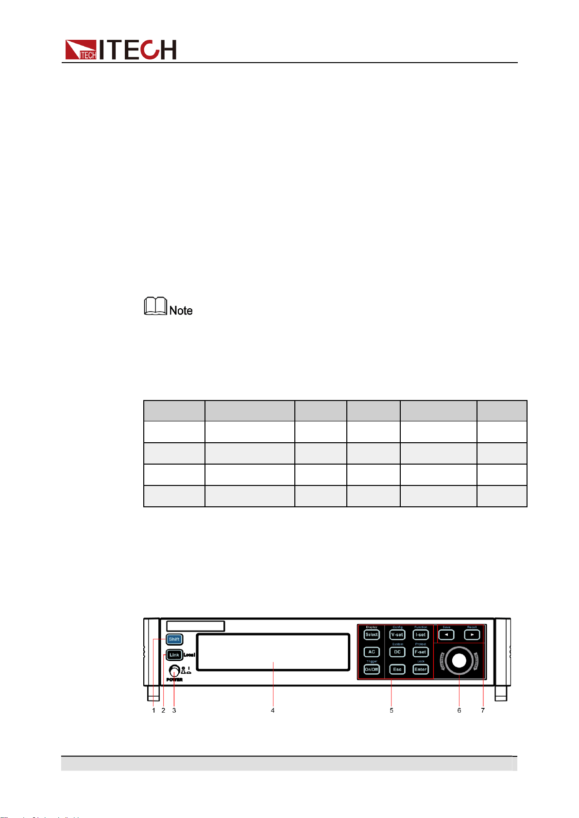
1.2
Front Panel at a Glance
The front panel of this series instruments is shown below.

Copyright © Itech Electronic Co., Ltd.
3
Quick Reference
1
[Shift]key Composite key, combined with other keys to realize
functions marked above keys.
2
[Link]
(Local)
key
The functions is described as follows.
•
[Link] key. When the instrument is connected to
the PC through the LAN interface, this key will
light up.
•
Local switch key. In remote control, press
[Shift] + [Link] (Local) keys to switch the instru-
ment to local control mode.
3
Power switch
Turns the instrument on or off.
4
Vacuum fluo-
Displays all instrument functions. The information
rescent display
changes based on selected function.
5
Function keys
Please refer to 1.3 Front Panel Keys at a Glance for
group
detailed description about the function keys.
6
Push button
rotary
The functions is described as follows.
•
Rotate the push button rotary to adjust the value
setting or scroll pages to view menu items. Ro-
tate the push button rotary clockwise to increase
the set value and anticlockwise to decrease the
set value
7 The left/right
navigation keys
and composite
keys
•
Pressing the push button rotary acts like press-
ing [Enter] key to confirm an operation.
The functions is described as follows.
•
The left and right navigation keys are used to
adjust the cursor to the specified position or
scrolls pages to view menu items.
•
Save/Recall the present settings.
1.3
Front Panel Keys at a Glance
The keys introduction of IT-M7700 series power source is shown as follows.
No. Name Description
Copyright © Itech Electronic Co., Ltd.
4
Quick Reference
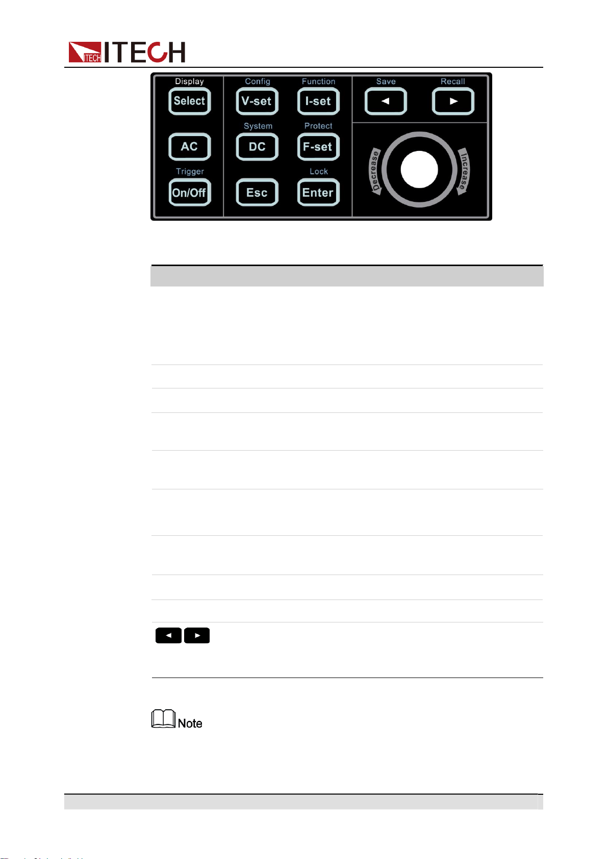
Key Name Description
Table 1–1 Keys Description
[Select] • AC Mode: Switches the AC main interface. Use this
key to switch the AC main interface 1 and AC main in-
terface 2.
•
DC Mode: [Select] key is not available.
[V-set] Sets the output voltage value.
[I-set] Sets the OCPrms value.
[AC] Press the [AC] key to set the instrument to AC output
mode.
[DC] Press the [DC] key to set the instrument to DC output
mode.
[F-set] • AC Mode: Sets the frequency value.
•
DC Mode: [F-set] key is not available.
[On/Off] Turns the instrument output on or off. When lit, indicates
that the output is on.
[Esc] Press this key to exit the current operation interface.
[Enter] Selects the menu item or confirm an operation.
The left and right navigation keys are used to adjust the
cursor to the specified position or scrolls pages to view
menu items.
Display is only used to prompt that the [Select] key is the display switch key
of the AC main interface, and has no other functions.
Copyright © Itech Electronic Co., Ltd.
5
Quick Reference
Key Name Description
Composite key [Shift], combined with other keys to realize functions marked
above keys. The detailed functions are listed as follows.
Table 1–2 Composite keys Description
[Shift]+[V-set](Config) Enter the Config menu.
[Shift]+[I-set](Function) Enter the Function menu.
[Shift]+[DC](System) Enter the System menu.
[Shift]+[F-set](Protect) Enter the Protect menu.
[Shift]+[On/Off]
(Trigger)
Generate a local trigger signal.
[Shift]+[Enter](lock) Turn the keyboard lock on or off.
[Shift]+
(Save)
Saves the present settings.
[Shift]+
(Recall)
Returns the instrument to the specified setup.
1.4
Rear Panel at a Glance
The rear panel of this series instruments is shown below.
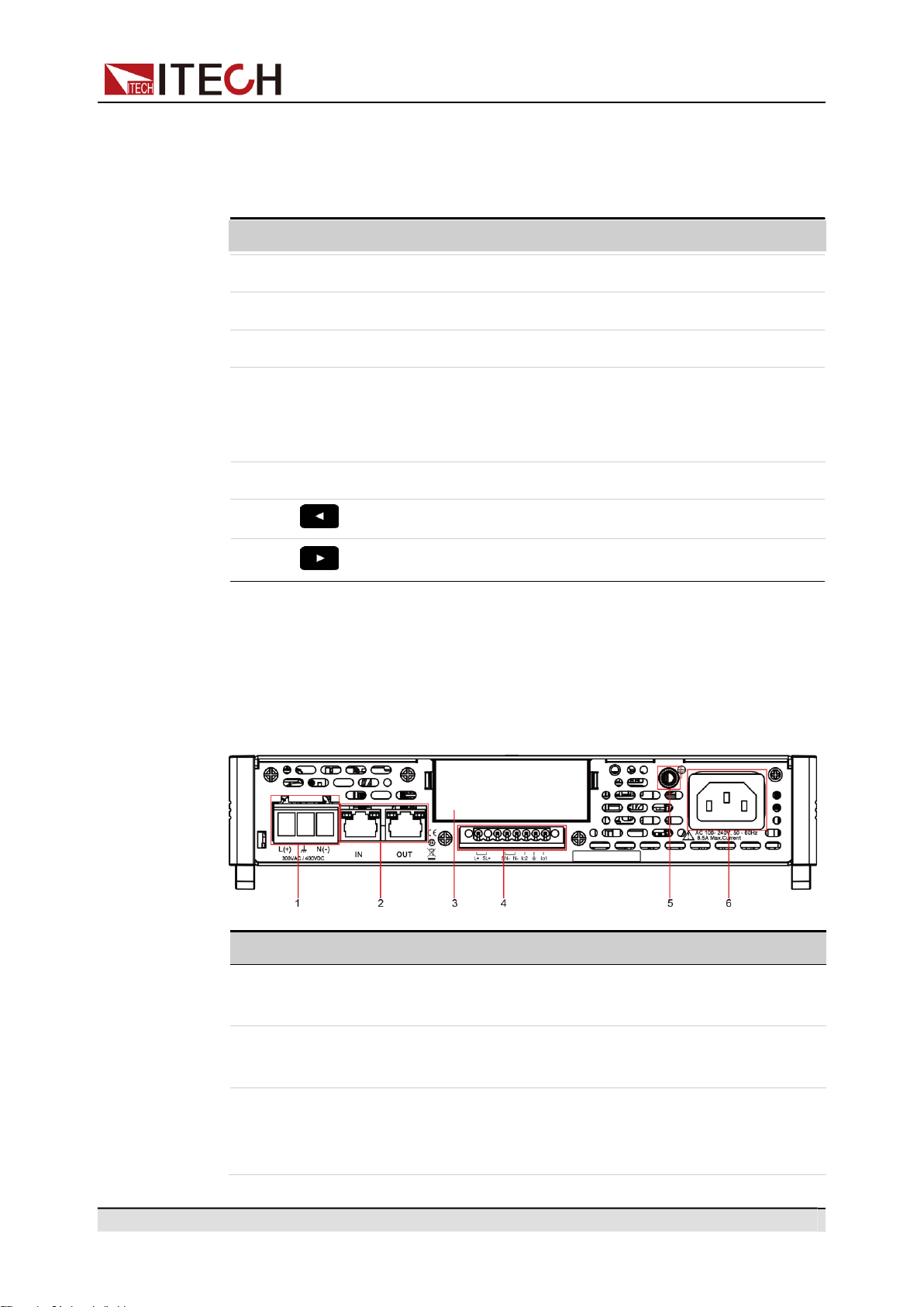
No.
Name
Description
1
Output terminals
AC or DC output terminals and chassis ground ter-
minals, used to connect DUT.
2
System bus
interfaces
Used for communication between instruments in
three phase or series operation feature.
3
Extended option-
al interface
Optional interfaces: (Plastic plugs are inserted by
default when the user does not purchase the
interface.)
Copyright © Itech Electronic Co., Ltd.
6
Quick Reference
4
Remote sense
terminals, Output
lock terminals
and I/O terminals
•
USB and LAN interfaces;
•
GPIB interface;
•
RS-232 and CAN interfaces;
•
Analog interface.
The descriptions of each terminals are as follows.
•
SL+ and SN- are remote sense terminals, used
for maximizing measurement accuracy.
•
L+ and N- are output terminals. These two ter-
minals are not suitable for transmitting large
current. Therefore, they cannot be connected
to the DUT, which are only used for short circuit
during local measurement.
•
I/O function has not yet fully supported.
5
Ground screw Ground screw for making chassis ground
connections.
6
AC power input
socket
Used to connect AC power to start instrument,
supports 110 V or 220 V.
1.5
Front Panel Display at a Glance
The IT-M7700 series power supply has different display information under the
AC mode and the DC mode. Details are as follows.
•
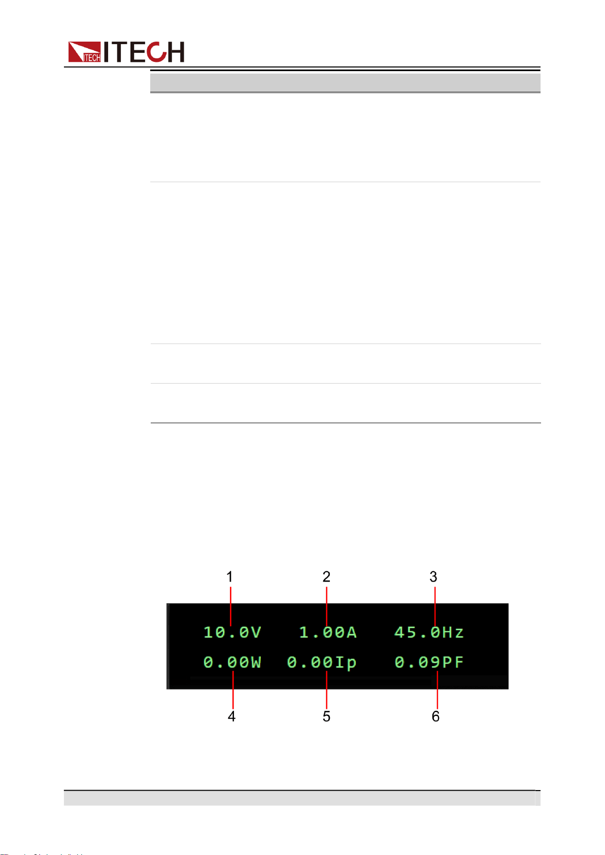
Under the AC mode, the AC main interface 1 is displayed as follows:
No. Name Description
Copyright © Itech Electronic Co., Ltd.
7
Quick Reference
1
Vac set value
/Vrms meter
value
2
OCPrms set
value
/Irms meter
value
3
Freq set value
/Freq meter
value
•
When output is Off, the AC voltage setting
value is displayed.
•
When output is On, the Meter value of volt-
age effective value is displayed.
•
When output is Off, the OCPrms setting val-
ue is displayed.
•
When output is On, the Meter value of cur-
rent effective value is displayed.
•
When output is Off, the frequency setting val-
ue is displayed.
•
When output is On, the Meter value of fre-
quency value is displayed.
4
P meter value Displays the Meter value of the active power.
5
Ip meter value Displays the Meter value of the maximum cur-
rent peak value.
6
PF meter value Displays the Meter value of the power factor.
•
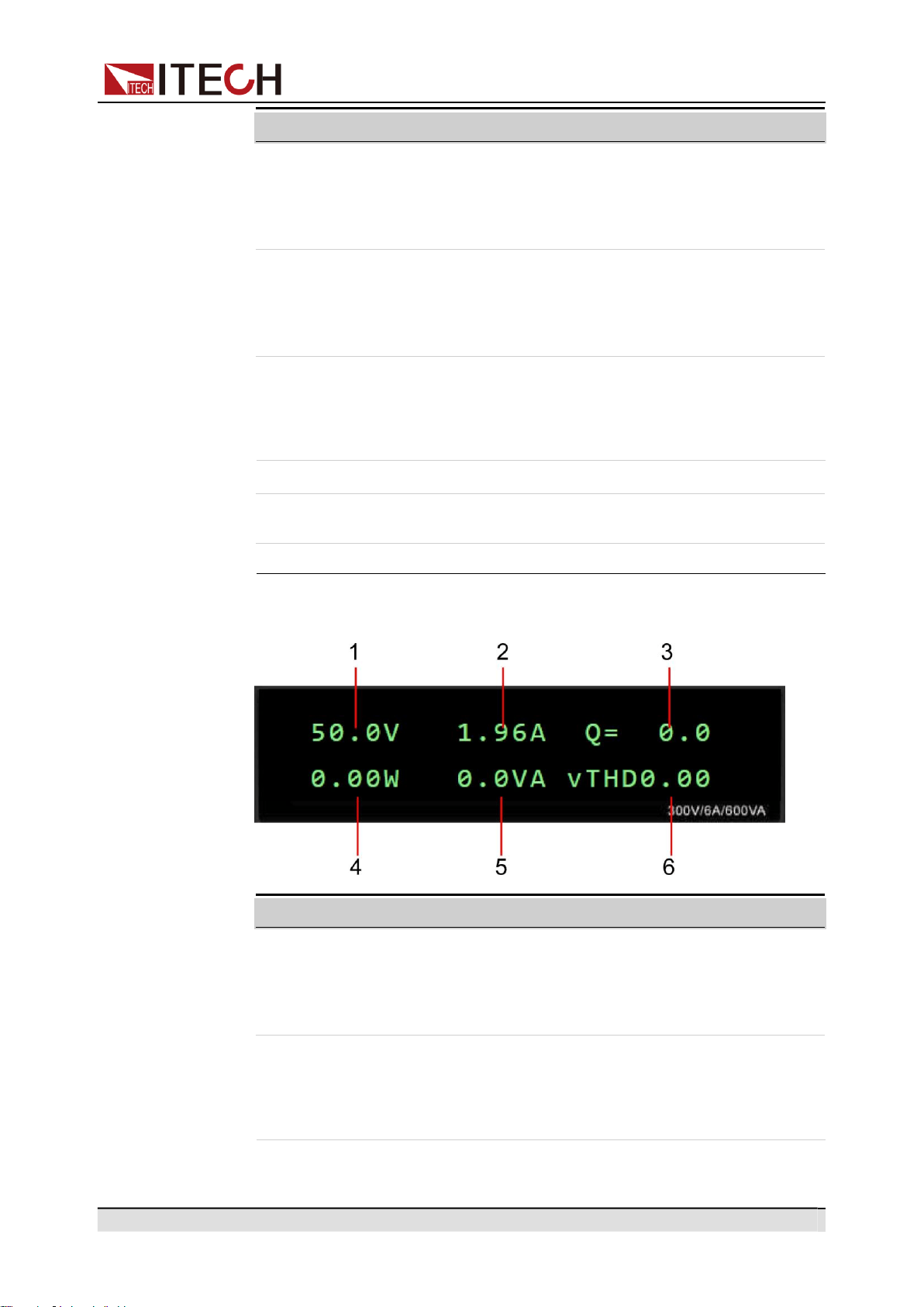
Under the AC mode, the AC main interface 2 is displayed as follows:
1
Vac set value
/Vrms meter value
2
OCPrms set value
/Irms meter value
•
When output is Off, the AC voltage set-
ting value is displayed.
•
When output is On, the Meter value of
voltage effective value is displayed.
•
When output is Off, the OCPrms setting
value is displayed.
•
When output is On, the Meter value of
current effective value is displayed.
No. Name Description
No. Name Description
Copyright © Itech Electronic Co., Ltd.
8
Quick Reference
No.
Name
Description
3
Q meter value
Displays the Meter value of the reactive
power.
4
P meter value
Displays the Meter value of the active
power.
5
S meter value
Displays the Meter value of the apparent
power.
6
vTHD meter value
Displays the Meter value of the total voltage
harmonic distortion.
iTHD meter value
Displays the Meter value of the total current
harmonic distortion.
Press the [Select] key to switch the AC main interface 1 and AC main in-
terface 2. When the AC main interface 1 is displayed, the [Select] key will
not light up; when the AC main interface 2 is displayed, the[Select] key
will light up. In the AC main interface 2, press the [Select] key to switch
the display among vTHD and iTHD, and press the [Select] key again to
switch back to AC main interface 1.
•
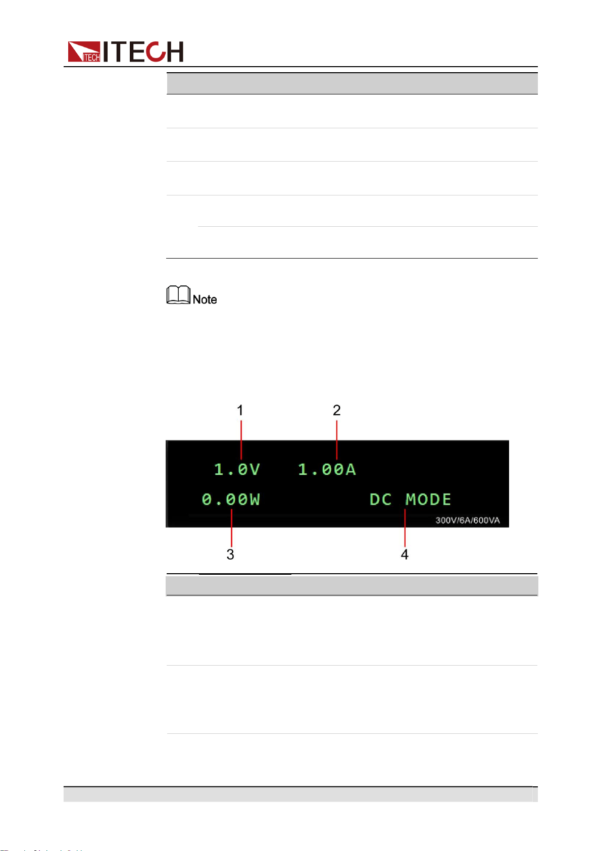
Under the DC mode, the DC main interface is displayed as follows:
1
Vdc set value
/Vdc meter
value
2
OCPrms set
value
/Idc meter value
•
When output is Off, the DC voltage setting
value is displayed.
•
When output is On, the Meter value of DC
voltage value is displayed.
•
When output is Off, the OCPrms setting val-
ue is displayed.
•
When output is On, the Meter value of DC
voltage value is displayed.
No. Name Description
Copyright © Itech Electronic Co., Ltd.
9
Quick Reference
No.
Name
Description
3
P meter value
Displays the Meter value of the power.
4
OUT Mode
Displays the output mode of the instrument.
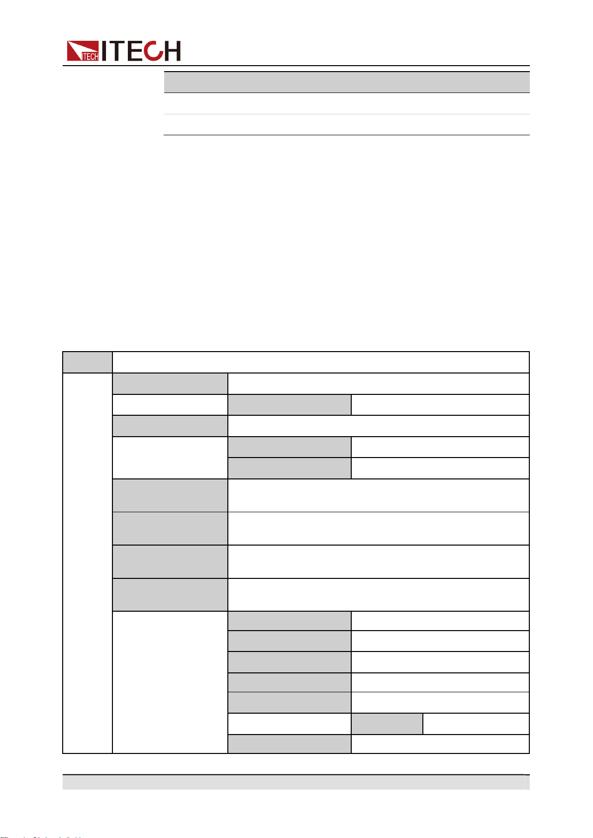
1.6
Configuration Menu at a Glance
Press the composite keys [Shift]+[V-set](Config) to enter into the Config menu
interface. At this time, the screen displays the optional menu. Click Rotary to
page up or page down the menu. Press the [Enter] key to enter into the se-
lected menu item. Press the [Esc] key to exit the menu function.
When the number before the menu item is in a flashing status (the digit is flash-
ing while the colon is not flashing), it indicates that this item is the selected
menu. The descriptions of configuration menu are listed in the table below.
Config
Configuration menu
I Range
Set the current measurement range.
High
High range
AC + DC
Set the AC + DC output mode.
Off
Turn off AC + DC output mode.
On
Turn on AC + DC output mode.
On Phase
Set the starting phase angle of the waveform. (only displayed
under the AC Mode)
Off Phase
Set the ending phase angle of the waveform. (only displayed
under the AC Mode)
V-Rise Time
Set the voltage rising time. (only displayed under the DC
Mode)
Wave
Set the output waveform type. (only displayed under the AC
Mode)
Sine
Sinusoidal
Square
Square
Triangle
Triangle
Saw
Sawtooth
Clip Sine
Clipped Sinusoidal
Clip Level
Clipped Percentage
THD1~THD30
30 sets of built-in waveforms.
Copyright © Itech Electronic Co., Ltd.
10
Quick Reference
USER1~USER5
5 sets of user-defined waveforms.
Parallel
Set the instruments to 3-phase or series operation mode.
Single
Set the instrument to single mode,
i.e., disable the 3-phase or series
operation mode.
600V/1A
Set the instruments to series oper-
ation mode.
3 Phase
Set the instruments to 3-phase op-
eration mode.
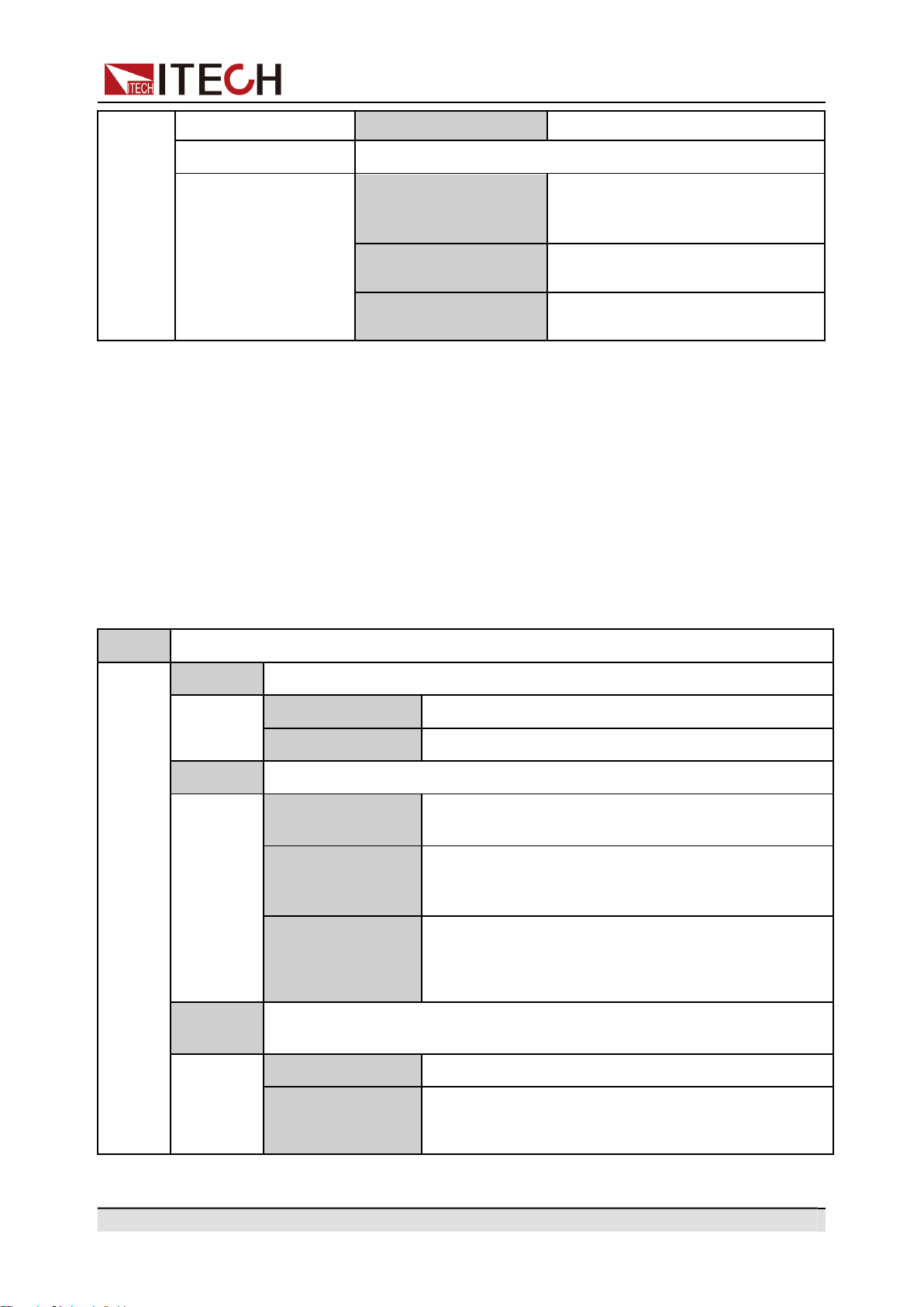
1.7
System Menu at a Glance
Press the composite keys [Shift]+[DC](System) to enter into the System menu
interface. At this time, the screen displays the optional menu. Click Rotary to
page up or page down the menu. Press the [Enter] key to enter into the se-
lected menu item. Press the [Esc] key to exit the menu function.
The descriptions of system menu are listed in the table below.
System
System menu.
Beep
Set the beeper status.
Off
Turn the beeper off.
On
Turn the beeper on.
PowerOn
Set the power-on state.
Reset
When the power source is powered on, the power
source will initialize some settings and output state.
Last
When the power source is powered on, the power
source will remain the same settings and output state
as last time you turned off the power source.
Last+Off
When the power source is powered on, the power
source will remain the same settings as last time you
turned off the power source, but the output state is
OFF state.
I/O Config
Select the interface communicated with the computer. The optional inter-
face is dynamically displayed based on different interface cards.
NULL
No optional communication interfaces.
GPIB
When the expansion slot is inserted into the IT-
E1205, you can select the GPIB communication
interface.
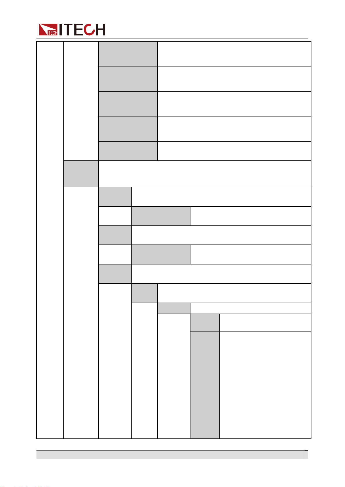
Copyright © Itech Electronic Co., Ltd.
11
Quick Reference
USB
When the expansion slot is inserted into the IT-
E1206 or IT-E1209, you can select the USB commu-
nication interface.
LAN
When the expansion slot is inserted into the IT-
E1206, you can select the LAN communication
interface.
RS232
When the expansion slot is inserted into the IT-
E1207, you can select the RS232 communication
interface.
CAN
When the expansion slot is inserted into the IT-
E1207, you can select the CAN communication
interface.
Analog
When the expansion slot is inserted into the IT-
E1208, you can select the Analog interface.
I/O Ad-
vance
Config
I/O Advance configuration. Based on the communication interface se-
lected by I/O Config, display configurable parameters of the communica-
tion interface in detail.
GPIB
When the I/O Config selects the GPIB interface, the following
information is displayed.
GPIB Address
Set the communication address within
the range from 1 to 30.
USB
When the I/O Config selects the USB interface, the following
information is displayed.
USBTM-
C&USBVCP
It is unnecessary to set the advancing
parameters for this interface.
LAN
When the I/O Config selects the LAN interface, the following
information is displayed.
IP
Config
Set the address of the instrument.
IP Mode
Set IP mode.
Auto
Auto: automatically configure
the address of the instrument.
Manu
Manual: manually configure
the address of the instrument
by entering values in the fol-
lowing five fields.
The following information only
appear when Manu is
selected.
•
IP: IP address
•
Gate: Default gateway
•
Mask: Subnet mask
•
DNS1: DNS1 (Primary
address)
Copyright © Itech Electronic Co., Ltd.
12
Quick Reference
•
DNS2: DNS2 (Secondary
address)
Server
Configure the LAN services.
Ping
Ping: Ping service state.
Off
On
mDNS
mDNS: mDNS service state.
Off
On
VXI-11
VXI-11: VXI-11 service state.
Off
On
Http
Http: Http service state.
Off
On
Telnet
Telnet: Telnet service state.
Off
On
Raw
Socket
RAWSocket: RAWSocket service state.
Off
On
Port
When the RAWSocket function is en-
abled, it is necessary to set the port num-
ber of the Raw- Socket interface.
LAN
Info
Viewing active LAN settings.
LAN Status
MAC Address
IP Address
Gateway Address
Submask Address
DHCP Server Address
DNS Server Address
Domain Name
Host Name
Description
LAN
Reset
Select whether to reset the LAN setting or not.
NO
YES
RS232
When the I/O Config selects the RS232 interface, the following
information is displayed.
Copyright © Itech Electronic Co., Ltd.
13
Quick Reference
Baudrate
Select the baud rate from the following
options: 4800, 9600, 19200, 38400,
57600, 115200. The data bit, parity bit
and stop bit are fixed: 8_None_1.
CAN
When the I/O Config selects the CAN interface, the following
information is displayed.
Can Address
Set the instrument address to a number
from 1 to 127.
Baudrate
Select the baud rate from the following
options: 125k, 250k, 500k.
Analog
When the I/O Config selects the Analog interface, the following
information is displayed.
Local/Analog
Enable or disable the analog control:
•
Local: local control;
•
Analog: external analog control.
Ext In Edge
Select the slope of the trigger signal: ris-
ing time or falling time.
External Cal
External voltage control calibration.
Relay Ctrl
Set the relay control.
Out Syn
The relay is linked with Output. When the instrument
output is On, the relay is closed; when the instrument
output is Off, the relay is open, and the instrument
and the load are electrically separated.
NC
The relay is normally closed. Whether the instrument
out is On or Off will not affect the operation of relay.
System
Reset
Select whether to restore the factory default settings or not.
No
Don’t restore the factory default settings.
Yes
Restore the factory default settings.
System
Info
View the system information.
Manufacturer
Display the manufacturer.
Model
Display the instrument model.
Version
Display the software version.
Serial Number
Display the serial number.
SCPI Error
Display SCPI command error information.
Last Cal. Date
Display last calibration date.
Copyright © Itech Electronic Co., Ltd.
14
Quick Reference
1.8
Optional Accessories
You can purchase accessories for the IT-M7700 series of instruments sepa-
rately, including the following:
•
Scalable interface
The interface expansion slot provided on the rear panel of the IT-M7700 ser-
ies instrument allows users to flexibly expand according to their needs. Dif-
ferent interface cards can be selected to achieve different functions.
Includes communication interface or external analog interface.
•
Cabinet installation
The IT-M7700 series instruments can be mounted on a standard 19-inch
cabinet. ITECH has prepared a special bracket for the user as a mounting
kit.
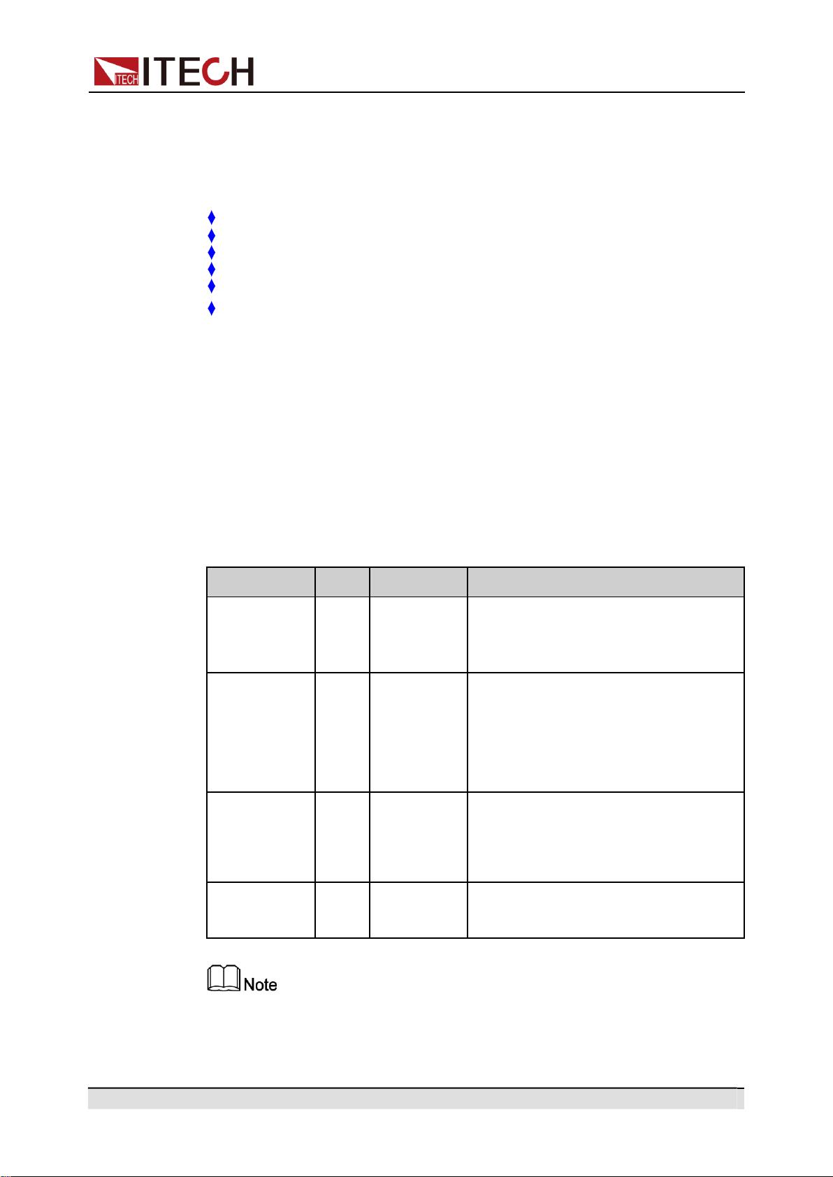
The detailed descriptions of the options are as follows.
The following optional accessories from ITECH are sold separately. Users
need to purchase separately.
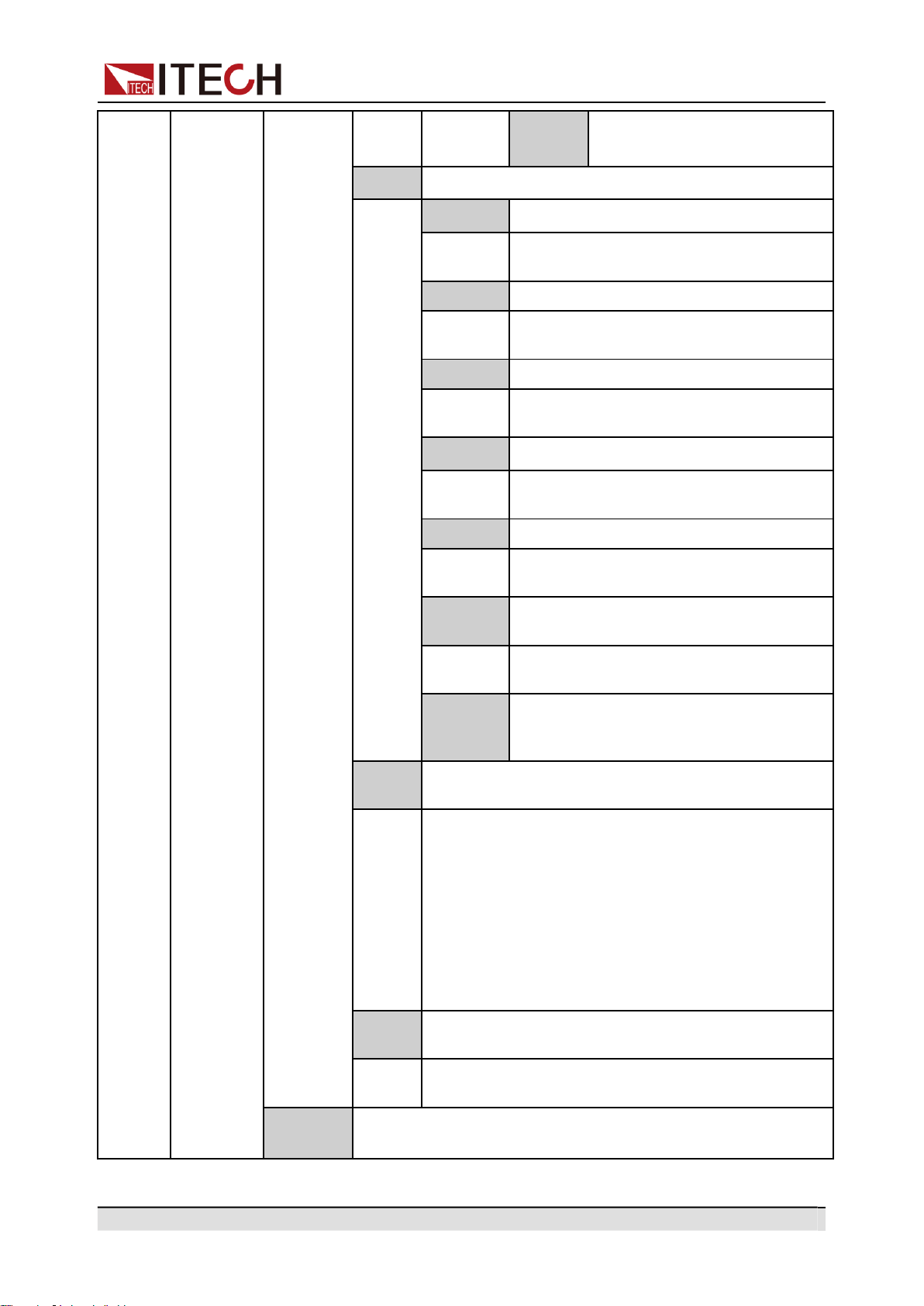
Device Name
Model
Description
GPIB communi-
cation interface
IT-E1205
When the user needs to use GPIB interface
to enable remote operation, this option is
the right choice.
USB/LAN com-
munication
interface
IT-E1206
When the user needs to use USB and LAN
interface to enable remote operation, this
option is the right choice.
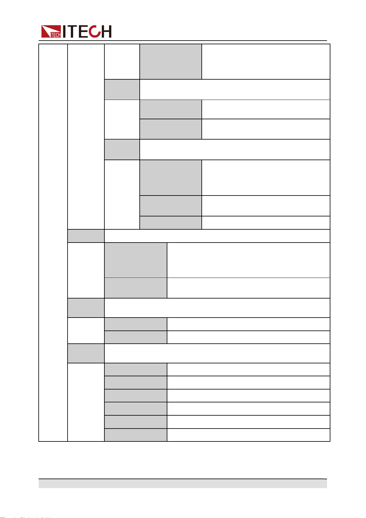
RS–232/CAN
communication
interface
IT-E1207
When the user needs to use RS–232 and
CAN interface to enable remote operation,
this option is the right choice.
Copyright © Itech Electronic Co., Ltd.
15
Quick Reference
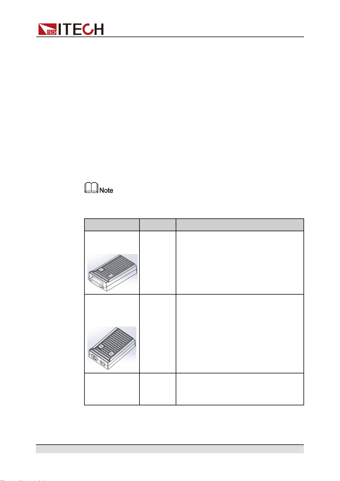
Device Name
Model
Description
External analog
communication
interface
IT-E1208
When the user needs to use external analog
function, this option is the right choice.
USB communica-
tion interface
IT-E1209
When the user needs to use USB interface
to enable remote operation, this option is
the right choice.
Cabinet installa-
tion kit
IT-E154
When the instrument needs to be installed
in cabinet, this kit is needed. Please refer to
《IT-E154 User Manual 》for detailed de-
scription about the installation method.
Hot swap is not available for the communication card and analog card. After
changing the communication card and analog card, you must re-start the
instrument.
Copyright © Itech Electronic Co., Ltd.
16
Inspection and Installation
2 Inspection and Installation
Verifying the Shipment
Instrument Size Introduction
Rack Mounting
Connecting the Power Cord
Connecting the Device Under Test (DUT)
Connecting the Interface
2.1
Verifying the Shipment
Unpack the box and check the contents before operating the instrument. If
wrong items have been delivered, if items are missing, or if there is a defect with
the appearance of the items, contact the dealer from which you purchased the
instrument immediately.
Table 2–1 Package box contents
Item
Qty.
Model
Remarks
Programma-
ble AC Power
Source
-
IT-M7700
series
This series include: IT-M7721/IT-
M7722/IT-M7721L/IT-M7722L
Power Cord
X 1
-
User may select an appropriate power
cord that matches the specifications of
power socket used in the area. See the
Section 2.4 Connecting the Power
Cord for details.
Multiple
instruments
connection
cables
X 1
IT-E251
When the user needs to connect the
System Bus interfaces between Multiple
instruments in series operation and
three-phase operation features, this
option is the right choice.
Ex-Factory
Test Report
X 1
-
It is the test report of the instrument be-
fore delivery.
Upon verification of the shipment, keep the package and relevant contents
thereof in a safe place. When returning the instrument for warranty service or
repair, the specified packing requirements shall be met.
Copyright © Itech Electronic Co., Ltd.
17
Inspection and Installation
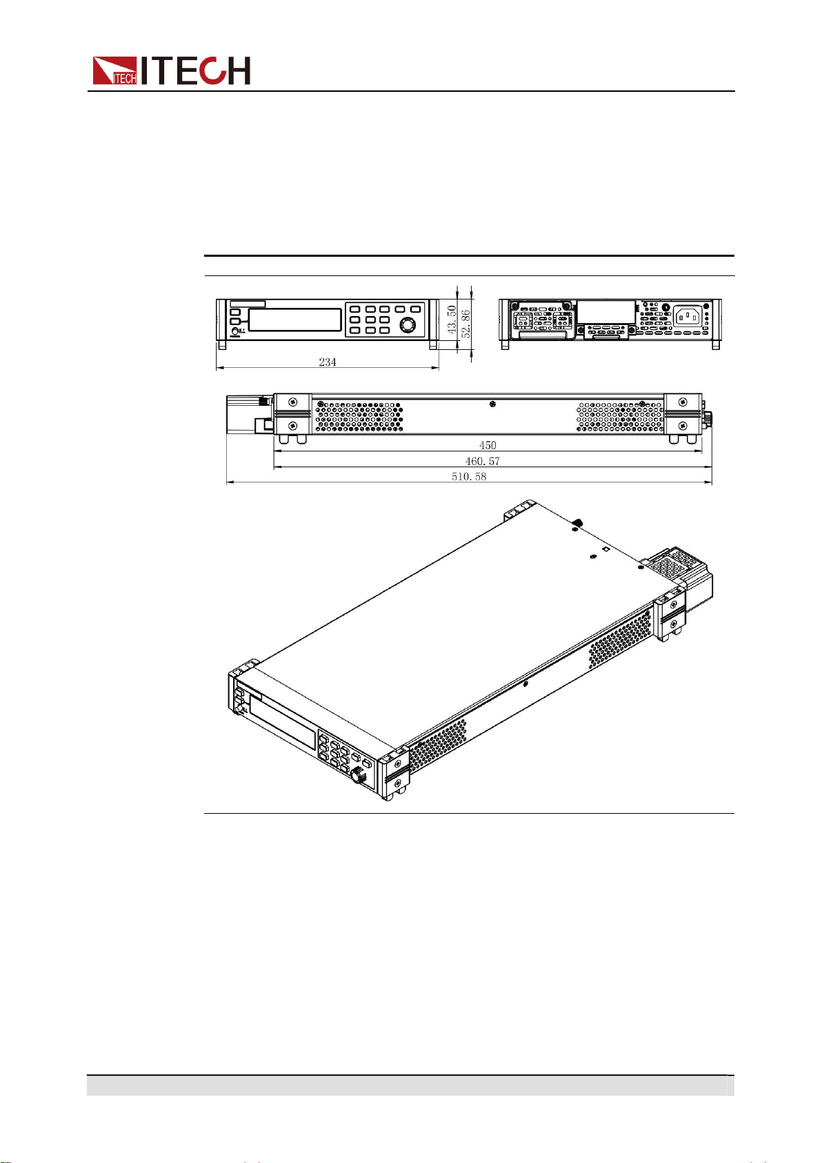
2.2
Instrument Size Introduction
The instrument should be installed at well-ventilated and rational-sized space.
Please select appropriate space for installation based on the instrument size.
The detailed dimension drawings of the IT-M7700 series are as follows:
IT-M7721/IT-M7722
2.3
Rack Mounting
IT-M7700 series power can be mounted on a standard 19” rack. ITECH pro-
vides user with IT-E154 rack, as an optional mount kit. The detailed operation
please refer to the User Manual of your mount kit.

Copyright © Itech Electronic Co., Ltd.
18
Inspection and Installation
2.4
Connecting the Power Cord
Precautions
To prevent electric shock and damage to the instrument, observe the following
precautions.
•
The power cords supplied with this product is certified for safety. In
case the supplied lines assembly needs to be replaced, or an exten-
sion lines must be added, be sure that it can meet the required
power ratings of this product. Any misuse voids the warranty of
this product.
•
Before connecting power cord, be sure to confirm that the power
voltage matches with the supply voltage.
•
Before connecting power cord, be sure to switch off the instrument.
Power switch is in Off position.
•
To avoid fire or electric shock, make sure to use the power cord
supplied by ITECH.
•
Do not use an extended power cord without protective grounding,
otherwise the protection function will fail.
•
Be sure to connect the main power socket to the power outlet with
protective grounding. Do not use terminal board without protective
grounding.
•
The instrument rear panel provides a separate screw used for chas-
sis ground. Please make proper connections. In the event of a fail-
ure, not using a properly grounded protective earth and grounded
outlet may result in personal injury or death due to electric shock.
Safety agency requirements dictate that there must be a way to
physically disconnect the AC mains cable from the unit. A dis-
connect device, either a switch or circuit breaker must be pro-
vided in the final installation. The disconnect device must be
close to the equipment, be easily accessible, and be marked as
the disconnect device for this equipment.
Categories of Power Cords
Please select appropriate power cords appropriate to local voltage based on the
specifications of power cords below. If purchased model fails to meet local volt-
age requirements, please contact distributor or factory for change.
Copyright © Itech Electronic Co., Ltd.
19
Inspection and Installation
China
IT-E171
United States &
Canada & Japan
IT-E172
Europe
IT-E173
England
IT-E174
AC Power Input Level
Working voltage for IT-M7700 series power is 100 ~ 240V, AC power input level:
100 ~ 240V, 50 ~ 60Hz.
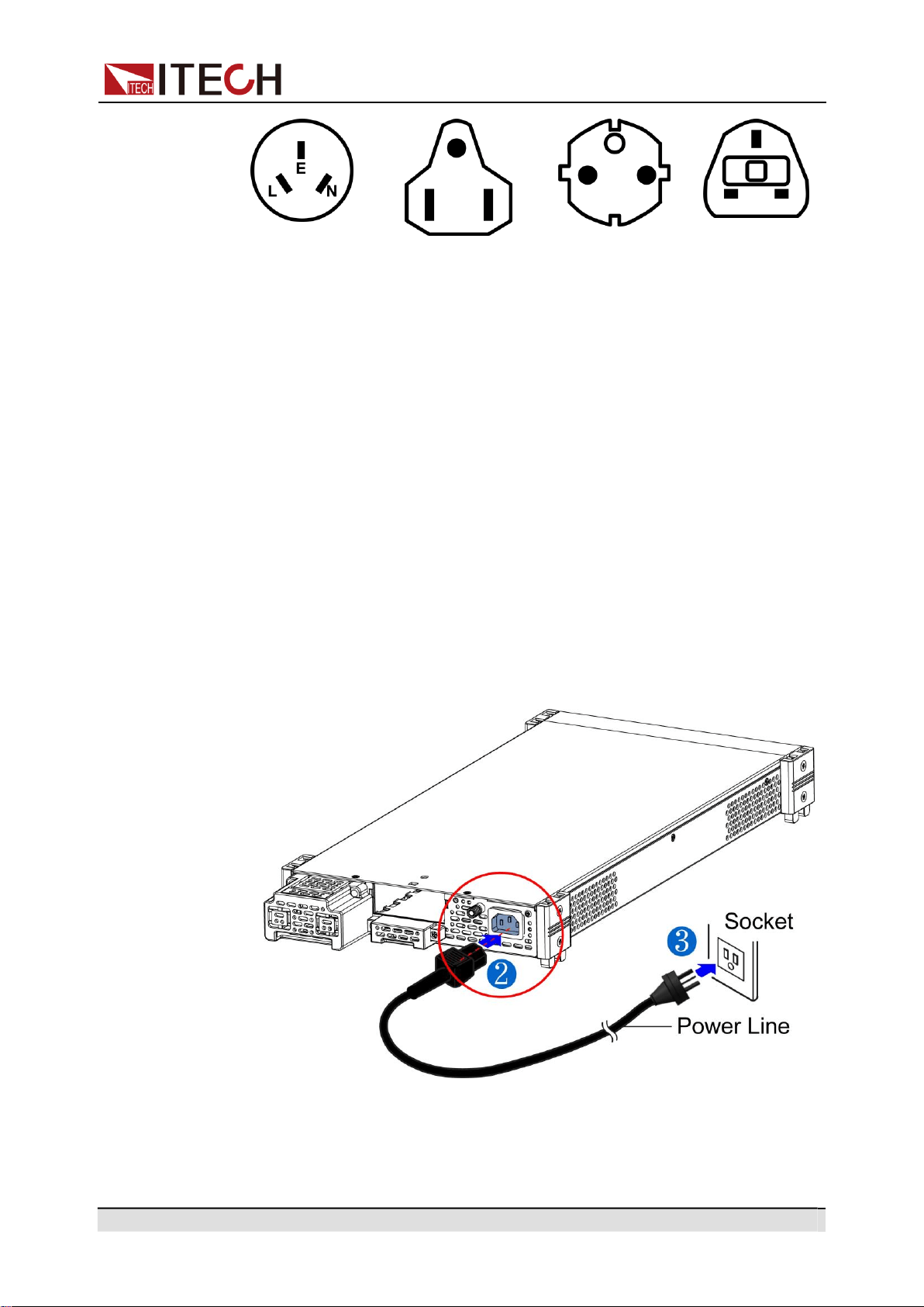
Connecting the Power Cord
To connect the power cord:
1.
Make sure that the front-panel power switch is in the Off position.
2.
Connect the female end of the supplied line cord to the AC receptacle on the
rear panel.
3.
Connect the plug of the power cord to a grounded AC outlet.
4.
Make proper connections of the chassis ground.

Copyright © Itech Electronic Co., Ltd.
20
Inspection and Installation
2.5
Connecting the Device Under Test (DUT)
The instrument supports two connection methods between power supply and
DUT: Local measurement and Remote sensing.
•
Local measurement The voltage sensed by the instrument is the voltage at
the output terminal of the instrument.
•
Remote sensing The voltage sensed by the instrument is the voltage at the
terminal of the remote object under test.
Precautions
To prevent electric shock and damage to the instrument, observe the following
precautions.
•
Before connecting DUT, be sure to switch off the power supply.
Power switch is in Off position, otherwise touching the output ter-
minals on the rear panel may result in personal injury or death due
to electric shock.
•
To avoid electrical shock, before testing, please make sure the rat-
ing values of the testing cables, and do not measure the current
that higher than the rating value. All test cables shall be capable of
withstanding the maximum short circuit output current of the
power supply without causing overheat.
•
If several loads are provided, each pair of load wires shall safely
withstand the rated short circuit output current of the power supply
under full load.
•
During wiring, check that the anode and cathode of the test lines
are properly and tightly connected; anode On and cathode Off are
prohibited.
Specification
Test cables are not standard accessories for the instrument. Please select op-
tional red and black test cables for individual sales based on the maximum cur-
rent value. For specifications of test cables and maximum current values, refer
to A.1 Specifications of Red and Black Test Lines for more information.
Connecting the DUT (Local Measurement)
The connection diagram and steps of local sensing are as follows:
Copyright © Itech Electronic Co., Ltd.
21
Inspection and Installation
1.
Before connecting the DUT, be sure that the instrument Power is in Off
position.
2.
Remove the cover of output terminal and remote sense terminal.
3.
Connect the L+ and SL+, N- and SN- for short circuit using the short clips on
the back panel of the instrument or electric wire. When using local sense,
the remote sense terminal cannot be disconnected.
4.
Loosen the screws of the output terminals and connect the red and black
test cables to the output terminals, and connect the ground terminal cor-
rectly. Re-tighten the screws.
5.
Thread the red and black test cables through the output terminals cover of
the instrument and install the cover.
6.
Directly connect the other end of the red and black cables to the DUT.
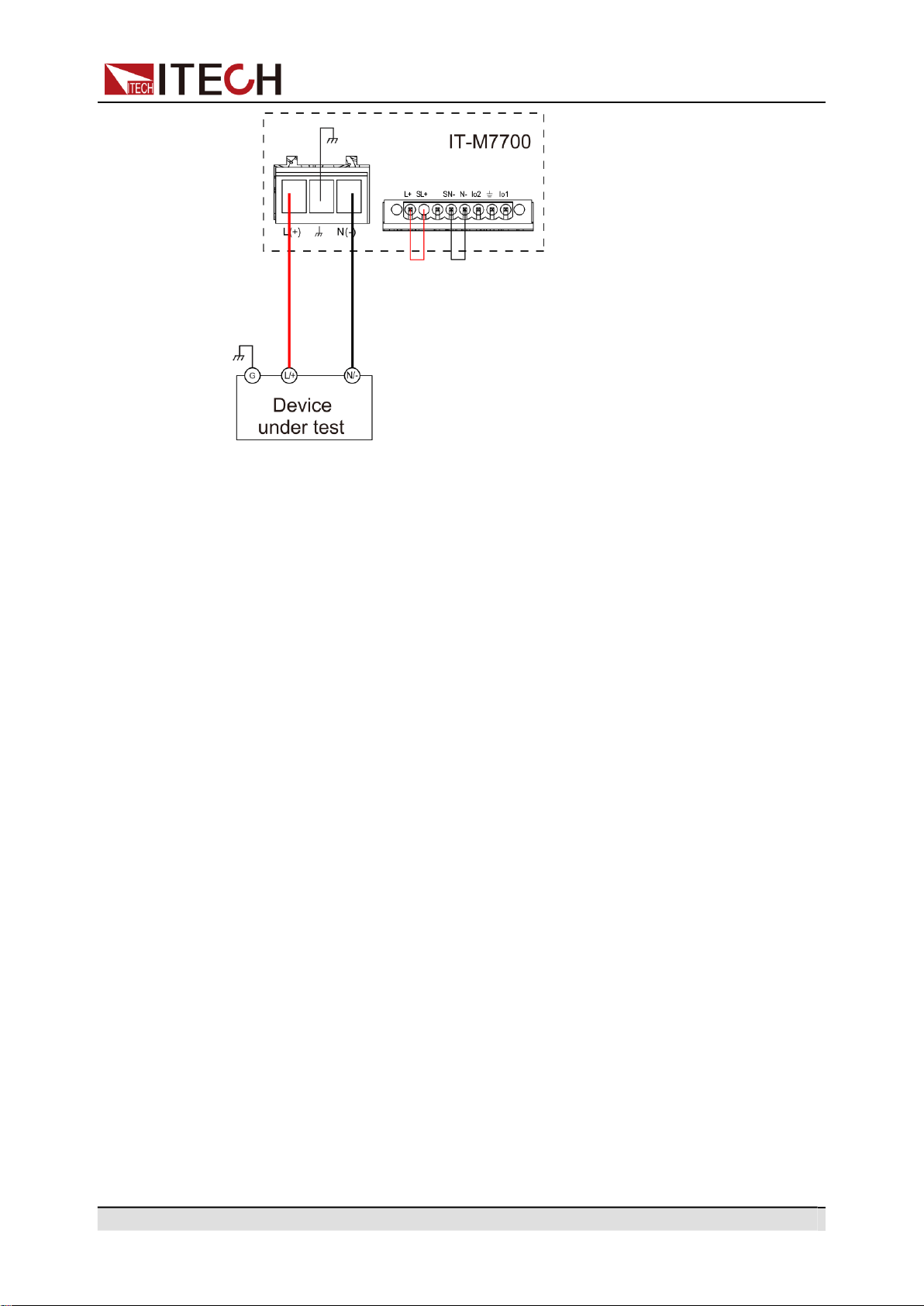
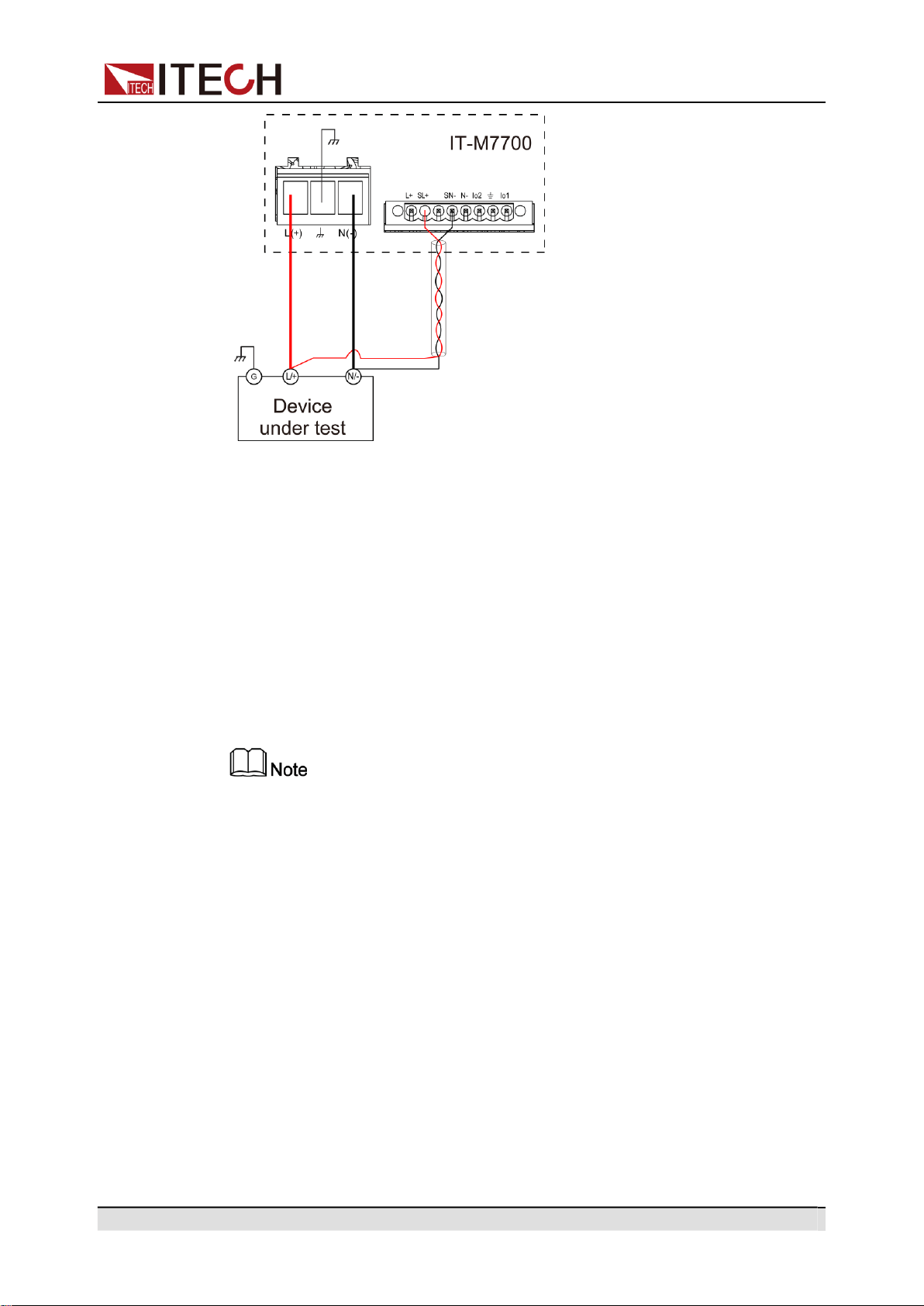
Connecting the DUT (Remote Sensing)
When the DUT consumes large current or the wires are too long, there is a volt-
age drop on the wires between the DUT and output terminal of the power sup-
ply. To maximize measurement accuracy, you can use remote sense wire
connections to monitor and improve the voltage adjustment on the DUT and
compensate for the voltage drop on the wires .
When the power supply is used for measuring battery charge in actual applica-
tions, the voltage drop of the wire will lead to voltage inconsistency of both ends
and inconsistency of the cutoff voltage of power supply and the actual voltage of
battery, resulting in inaccurate measurement.
The connection diagram and steps of remote sensing are as follows:
Copyright © Itech Electronic Co., Ltd.
22
Inspection and Installation
1.
Confirm that the power switch is in the Off position
2.
Remove the cover of output terminal and remote sense terminal.
3.
Disconnect the wires/short clips between SL+ and L+, SN- and N-.
4.
Use armored twisted-pair cables to connect the remote sense terminals and
the device under test.
5.
Loosen the screws of the output terminals and connect the red and black
test cables to the output terminals, and connect the ground terminal cor-
rectly. Re-tighten the screws.
6.
Install the terminal cover, leave the other end of remote sense cables and
the red and black cables outside.
7.
Connect the other end of the remote sense cables and the red and black ca-
bles to the DUT.
Test lines and sense lines should be as short as possible, and sense lines
should be twisted together.
2.6
Connecting the Interface
The IT-M7700 series power supply has no standard-equipped interfaces card.
Users can purchase interface cards separately. Users can choose one of RS-
232, USB, GPIB, LAN, CAN to communicate with the computer. For details, see
1.8 Optional Accessories
The reserved interface card installation slot is on the rear panel of the instru-
ment. Users can install it directly after purchasing the interface card. Hot swap
is not available for the interface card. After changing the interface card, you
must re-start the instrument.
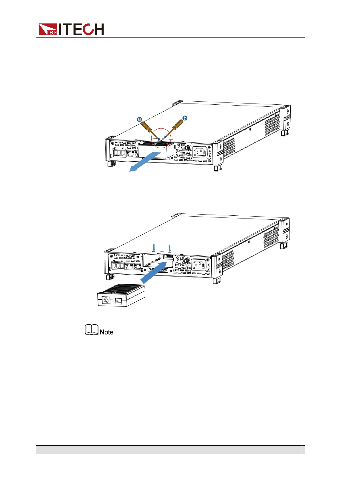
The installing steps for the purchased interface card are as follows:
Copyright © Itech Electronic Co., Ltd.
23
Inspection and Installation
1.
Remove the plug of the rear panel interface.
a.
Use a small flat screwdriver to press the clip at the upper cover opening.
b.
At the same time, use another small flat screwdriver to stir the slots one
by one from another opening of the upper cover, and push the plastic
plug out.
2.
Install the purchased communication card. Taking the LAN+USB interface
card as an example, push the card into the slot and secure with the screws
from the upper cover, it is shown as follow.
Firstly loosen the screws between upper cover and communication card and
removing the communication card like removing the plug, please use the
tools and remove it.
2.6.1
USB Interface
When the optional interface card is a stand-alone USB interface (IT-E1209) or
USB+LAN interface (IT-E1206), the following can help users quickly understand
the steps required to connect the USB interface. The figure below shows a typi-
cal USB interface system.

Copyright © Itech Electronic Co., Ltd.
24
Inspection and Installation
Take the IT-E1209 communication card box as an example. If you install IT-
E1206, please refer to the actual interface position.
The operation steps to use the USB interface are as follows.
1.
Refer to the USB connection diagram, Connect the power supply and the
computer using a cable with two USB interfaces (each end).
2.
Press the composite keys [Shift] + [DC](System) to enter into the system
menu interface.
3.
Rotate the knob to select I/O Config and press [Enter] key to confirm.
4.
Rotate the knob to select USB and press [Enter] key to confirm. The USB
communication supports the following two interface types and no need to se-
lect manually..
•
TMC: USB_TMC interface. When the host software uses USBTMC for
communication, this USB is the USB_TMC interface.
•
VCP: USB_VCP virtual serial port. When the host software uses the
USBVCP for communication(The WIN7/XP system needs to be installed
with IT-7722-VCP.inf. Download from the ITECH website or contact
ITECH agent), this USB is the USB_VCP interface.
5.
Press [Esc] to exit the system menu setting.
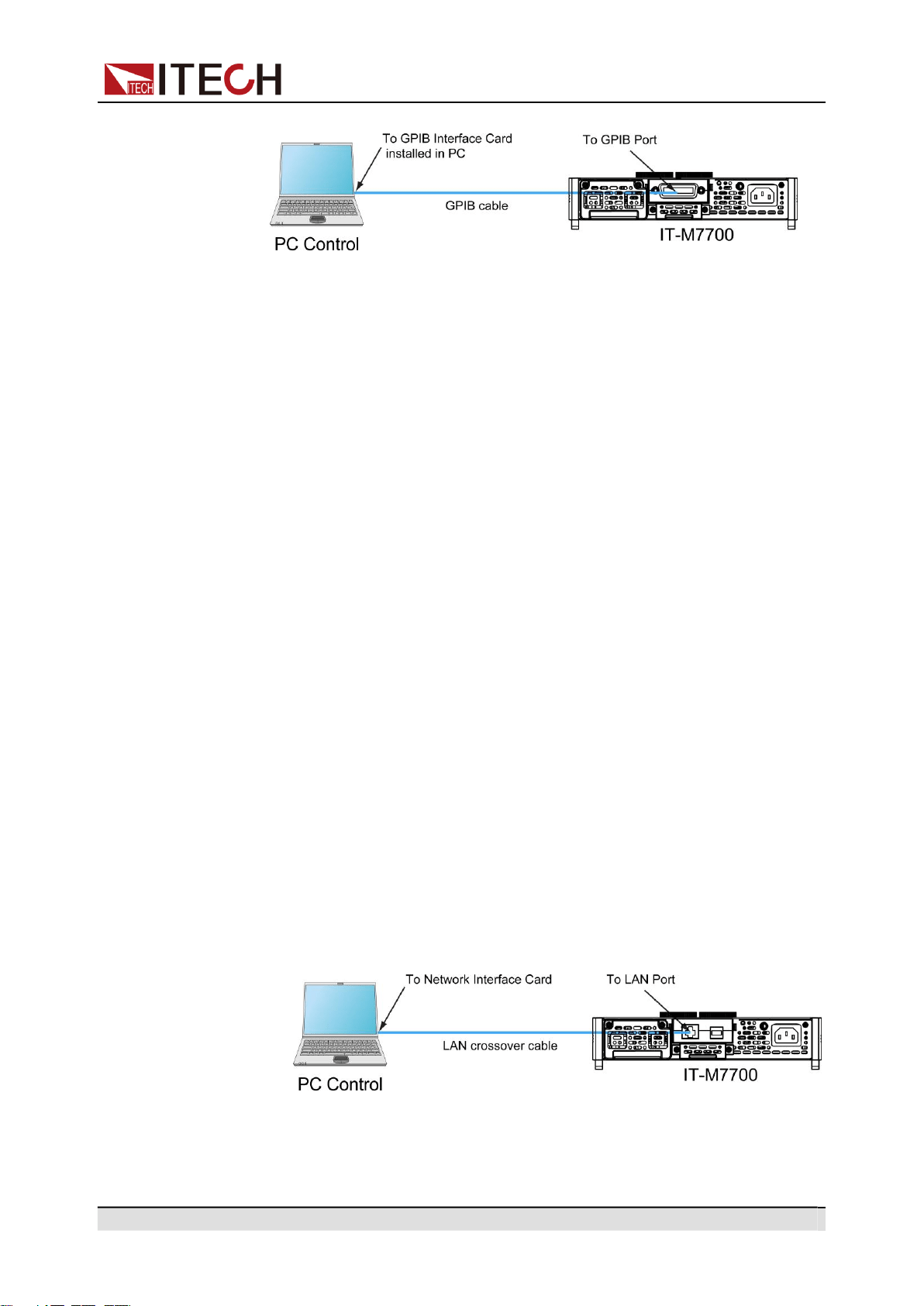
2.6.2
GPIB Interface
When the optional interface card is a GPIB interface (IT-E1205), you need to
know the following. Each device on the GPIB (IEEE-488) interface must have a
unique whole number address between 1 and 30. Your computer’s GPIB inter-
face card address must not conflict with any instrument on the interface bus.
This setting is nonvolatile; it will not be changed by power cycling or *RST. The
figure below shows a typical GPIB interface system.
Copyright © Itech Electronic Co., Ltd.
25
Inspection and Installation
The operation steps to use the GPIB interface are as follows.
1.
Refer to the GPIB connection diagram, Connect the power supply and the
computer using a IEEE-488 bus.
2.
Press the composite keys [Shift] + [DC](System) to enter into the system
menu interface.
3.
Rotate the knob to select I/O Advance Config and press [Enter] to enter
the GPIB advanced setting interface.
4.
Rotate the knob to select GPIB Address and press [Enter] key to confirm.
5.
Use left and right keys or rotate the knob to adjust the GPIB address and
press [Enter] key to confirm.
6.
Press [Esc] to exit the system menu setting.
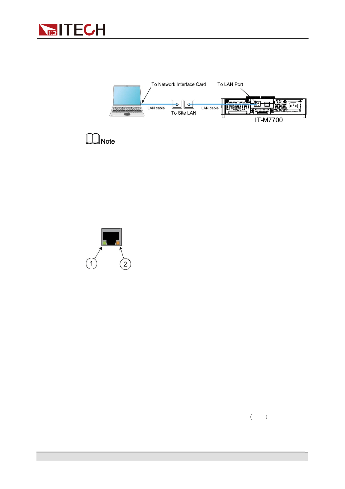
2.6.3
LAN Interface
When the user's optional interface card is a LAN+USB interface (IT-E1206), the
following is required to use the LAN interface.
Connect Interface
Use the following steps to quickly connect your instrument to your LAN and con-
figure it. Two typical LAN interface systems are described below: private LAN
and site LAN.
•
Connect to the private LAN
A private LAN is a network in which LAN-enabled instruments and com-
puters are directly connected. They are typically small, with no centrally
managed resources. When connected to a computer, a crossover cable can
be used to connect directly to the computer via the LAN interface.
•
Connect to the site LAN
A site LAN is a local area network in which LAN-enabled instruments and
computers are connected to the network through routers, hubs, and/or
Copyright © Itech Electronic Co., Ltd.
26
Inspection and Installation
switches. They are typically large, centrally-managed networks with services
such as DHCP and DNS servers. When connected to a computer, a direct
attached network cable can be used to connect to the router, and the com-
puter is also connected to the router.
•
When using one crossover cable to connect PC directly, the gateway address of
the instrument should be consistent with that of the PC, and the IP address
should be at the same network segment with the PC’s IP address.
•
When the instrument and computer are connected to the router, an independent
IP address must be assigned for the instrument.
LAN Status Indicator
The lower icon notes the two status LEDs located at the bottom of the LAN port.
If neither of the LEDs is lit, the network is not connected.
•
Position 1: when lit, it indicates that the LAN port is connected.
•
Position 2: When flashing, it indicates that the LAN port is receiving or send-
ing a message.
Configure LAN Interface Information
When shipped, DHCP is on, which may enable communication over LAN. The
letters DHCP stands for Dynamic Host Configuration Protocol, a protocol for as-
signing dynamic IP addresses to devices on a network. With dynamic address-
ing, a device can have a different IP address every time it connects to the
network.
The user can view the related information of LAN interface or configure the com-
munication parameters in system menu.
•
Automatically configure the address of the instrument. Auto
When selected, the instrument will first try to obtain an IP address from a
DHCP server. If a DHCP server is found, the DHCP server will assign an IP

Copyright © Itech Electronic Co., Ltd.
27
Inspection and Installation
address, Subnet Mask, and Default Gateway to the instrument. If a DHCP
server is unavailable, the instrument will try to obtain an IP address using
AutoIP. AutoIP automatically assigns an IP address, Subnet Mask, and De-
fault Gateway addresses on networks that do not have a DHCP server.
•
Manually configure the address of the instrument. Manual
Set the following parameter. The following information only appear when
Manual is selected.
–
IP: This value is the Internet Protocol (IP) address of the instrument. An
IP address is required for all IP and TCP/IP communications with the in-
strument. An IP Address consists of 4 decimal numbers separated by pe-
riods. Each decimal number ranges from 0 through 255 with no leading
zeros (for example, 169.254.2.20).
–
Gate: This value is the IP Address of the default gateway that allows the
instrument to communicate with systems that are not on the local subnet,
as determined by the subnet mask setting. The same numbering notation
applies as for the IP Address. A value of 0.0.0.0 indicates that no default
gateway is defined.
–
Mask: This value is used to enable the instrument to determine if a client
IP address is on the same local subnet. The same numbering notation
applies as for the IP Address. When a client IP address is on a different
subnet, all packets must be sent to the Default Gateway.
–
DNS1: This field enters the primary address of the server. Contact your
LAN administrator for server details. The same numbering notation ap-
plies as for the IP Address. A value of 0.0.0.0 indicates that no default
server is defined.
DNS is an internet service that translates domain names into IP ad-
dresses. It is also needed for the instrument to find and display its host
name assigned by the network. Normally, DHCP discovers the DNS ad-
dress information; you only need to change this if DHCP is unused or not
functional.
–
DNS2: This field enters the secondary address of the server. Contact
your LAN administrator for server details. The same numbering notation
applies as for the IP Address. A value of 0.0.0.0 indicates that no default
server is defined.
Operation Steps:
1.
Press the composite keys [Shift] + [DC](System) to enter into the system
menu interface.
2.
Rotate the knob to select I/O Config and press [Enter] key to confirm.
3.
Rotate the knob to select LAN and press [Enter] key to confirm.
4.
Rotate the knob to select I/O Advance Config and press [Enter] to enter
the LAN advanced setting interface.
5.
Rotate the knob to select IP Config and press [Enter] key to set the instru-
ment address.
6.
Rotate the knob to select IP Mode and press [Enter] key to select the IP set-
ting mode.

Copyright © Itech Electronic Co., Ltd.
28
Inspection and Installation
•
Auto: automatically configure the addressing of the instrument;
•
Manu: manually configure the addressing of the instrument. If Manu is
selected, set the parameters such as IP and Gate.
7.
After setting, press [Esc] to exit.
Reset the LAN Setting
After configuring the LAN settings, the user need to reset the settings to make it
valid in the instrument. The operation steps to reset the LAN settings are as
follows.
1.
Press the composite keys [Shift] + [DC](System) to enter into the system
menu interface.
2.
Rotate the knob to select I/O Config and press [Enter] key to confirm.
3.
Rotate the knob to select LAN and press [Enter] key to confirm.
4.
Rotate the knob to select I/O Advance Config and press [Enter] to enter
the LAN advanced setting interface.
5.
Rotate the knob to select LAN Reset and press [Enter] key to reset the LAN
parameter configuration.
•
NO: indicates refuse to reset the LAN setting.
•
YES: indicates reset the LAN setting.
View LAN Interface Information
The operation steps to view the LAN interface information are as follows.
1.
Press the composite keys [Shift] + [DC](System) to enter into the system
menu interface.
2.
Rotate the knob to select I/O Config and press [Enter] key to confirm.
3.
Rotate the knob to select LAN and press [Enter] key to confirm.
4.
Rotate the knob to select I/O Advance Config and press [Enter] to enter
the LAN advanced setting interface.
5.
Rotate the knob to select LAN Info and press [Enter] to view the LAN inter-
face information.
6.
Rotate the knob to view the LAN interface information. Refer to 1.7 System
Menu at a Glance for more information.
7.
After setting, press [Esc] to exit.
Enable LAN services
The configurable services include: mDNS, Ping, Http, Telnet, VXI-11 and Raw
Socket. When using the LAN interface, these services are enabled by default
and can be used directly. If you need to turn it off or on again, please refer to the
following steps:

Copyright © Itech Electronic Co., Ltd.
29
Inspection and Installation
1.
Press the composite keys [Shift] + [DC](System) to enter into the system
menu interface.
2.
Rotate the knob to select I/O Config and press [Enter] key to confirm.
3.
Rotate the knob to select LAN and press [Enter] key to confirm.
4.
Rotate the knob to select I/O Advance Config and press [Enter] to enter
the LAN advanced setting interface.
5.
Rotate the knob to select Server and press [Enter] key to enable or disable
the LAN service.
6.
Rotate the knob to select the service you want to enable and press[Enter]
key to confirm.
7.
Rotate the knob to switch On and Off options. After selecting On or Off,
press [Enter] key to confirm.
•
On: indicates enable the service.
•
Off: indicates disable the service.
8.
When enabling the Raw Socket service, the user needs to set the corre-
sponding Port.
9.
After setting, press [Esc] to exit.
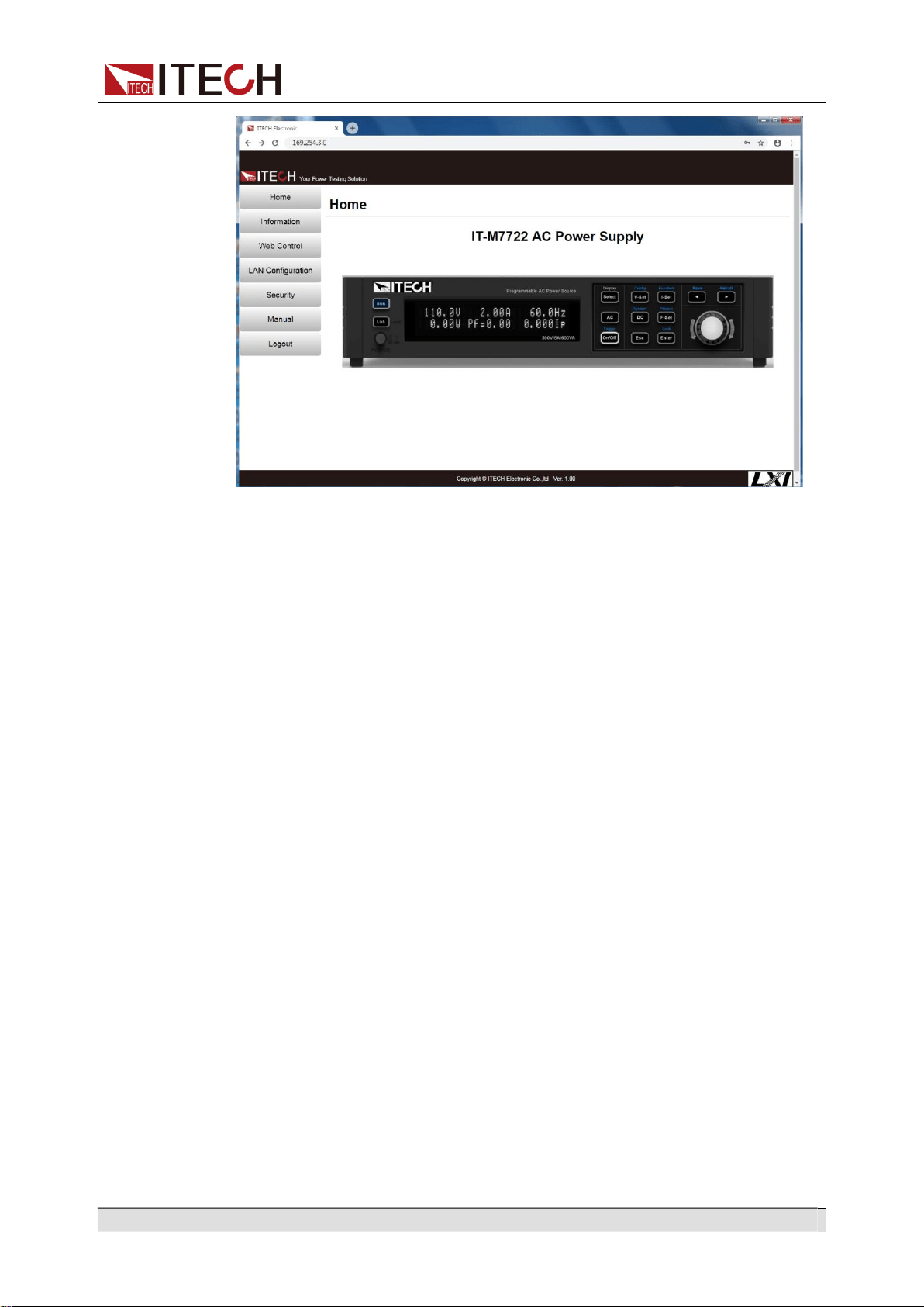
2.6.3.1
Using Http Server
The instrument has a built-in Http server for monitoring and controlling the in-
strument via a Http browser in PC. To use the Http server, connect the instru-
ment and PC over LAN interface and enter the instrument's IP address into the
address bar at the top of your PC's Http browser, you can access the front panel
control functions including the LAN configuration parameters.
•
If you want to remotely control the instrument using the built-in Http server, you
must enable the Http service. See 2.6.3 LAN Interface for details.
•
Up to six simultaneous connections are allowed. With additional connections,
performance will be reduced.
As shipped, the login password of the Http interface defaults to 12345678. To
change the password, click the Security button in the navigation bar on the left
side of the window after login.
Enter the password and then click the LOGIN button, the Http interface will ap-
pear in the browser as shown below.
Copyright © Itech Electronic Co., Ltd.
30
Inspection and Installation
You can select different interfaces by clicking the seven buttons shown in the
navigation bar on the left side of the window. The detailed descriptions are as
follows.
•
Home: Http home interface, displays the model and appearance of the
instrument.
•
Information: Displays the serial number of the instrument and more system
information as well as LAN configuration parameters.
•
Web Control: Enables the Web control to begin controlling the instrument.
This page allows you to monitor and control the instrument.
•
LAN Configuration: Reconfigure the LAN parameters.
•
Security: Change the password and control access to the Http interface.
•
Manual: Go to the ITECH official website and view or download the relevant
documents.
•
Logout: Logout the Http interface.
2.6.3.2
Using Telnet
The Telnet utility (as well as sockets), is another way to communicate with the
instrument without using I/O libraries or drivers. In all cases, you must first es-
tablish a LAN connection from your computer to the instrument as previously
described.
In an MS-DOS Command Prompt box, type “telnet hostname” where hostname
is the instrument’s hostname or IP address. Press the Enter key and you should
get a Telnet session box with a title indicating that you are connected to the
Copyright © Itech Electronic Co., Ltd.
31
Inspection and Installation
Pins Description
instrument and 23 is the instrument’s telnet port. Type the SCPI commands at
the prompt.
2.6.3.3
Using Sockets
The instruments allow any combination of up to six simultaneous
socket and telnet connections to be made.
ITECH instruments have SCPI socket services, which can be used to send and
receive ASCII/SCPI commands, queries, and query responses. All commands
must be terminated with a new line for the message to be parsed. All query re-
sponses will also be terminated with a new line.
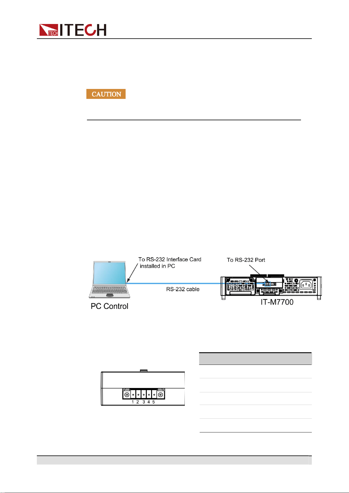
2.6.4
RS-232 Interface
When the optional interface card is RS232+CAN interface (IT-E1207), the fol-
lowing can help users quickly understand the steps required to connect the RS-
232 interface. The figure below shows a typical RS-232 interface system that
connects to your computer using an RS-232 cable.
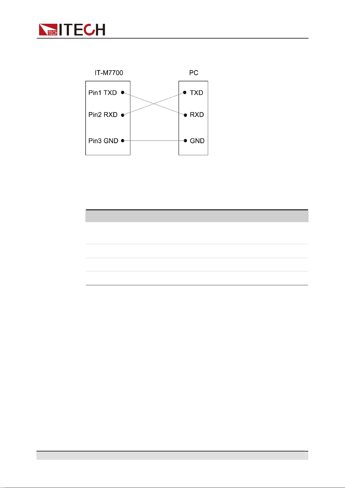
Definition of RS-232 Pins
The definition of RS-232 pins are as follows.
IT-E1207
1
TXD, transmit data
2
RXD, receive data
3
GND
4
CAN_H
5
CAN_L
Copyright © Itech Electronic Co., Ltd.
32
Inspection and Installation
Name Description
RS-232 Connection
Directly connected to the computer, as shown below:
RS–232 Configuration
The user needs to configure the RS–232 interface parameters in the system
menu before using the remote control. The RS–232 interface parameters are as
follows.
Baud rate Select the baud rate from the following options: 4800,
9600, 19200, 38400, 57600, 115200.
Data Bit 8 (fixed)
Parity bit None (fixed)
Stop bit 1(fixed)
The operation steps are as follows.
1.
Press the composite keys [Shift] + [DC](System) to enter into the system
menu interface.
2.
Rotate the knob to select I/O Config and press [Enter] key to confirm.
3.
Rotate the knob to select RS-232 and press [Enter] key to confirm.
4.
Rotate the knob to select I/O Advance Config and press [Enter] key to en-
ter the RS-232 Advancing Setting interface.
5.
Rotate the knob to select Baud Rate and press [Enter] key to confirm.
6.
Use left and right keys or rotate the knob to set the communication baud
rate, and press [Enter] key to confirm.
7.
Press [Esc] to exit the system menu setting.
Copyright © Itech Electronic Co., Ltd.
33
Inspection and Installation
Pins Description
RS-232 Troubleshooting
If you meet some problems when communicating with PC by RS-232 interface,
please check the following items:
•
PC and power source must have the same baud rate.
•
Ensure you have used the correct communication cable (CAN_H, CAN_L).
Please pay attention that some cable may not have a correct internal wiring
even it is with an appropriate interface.
•
The cable must be connected to the correct serial ports (COM1, COM2, etc)
of PC.
2.6.5
CAN Interface
When the optional interface card is RS232+CAN interface (IT-E1207), the fol-
lowing can help users quickly understand the steps required to connect to the
CAN interface.
The following figure shows the CAN interface system. The user can select the
CAN interface converter to connect to your computer according to the actual sit-
uation. Take the CAN to USB interface device as an example.
Definition of CAN Pins
The definition of CAN pins are as follows.
IT-E1207
1
TXD, transmit data
2
RXD, receive data
3
GND
4
CAN_H
5
CAN_L

Copyright © Itech Electronic Co., Ltd.
34
Inspection and Installation
Name Description
CAN Configuration
The user needs to configure the CAN interface parameters in the system menu
before using the remote control. The CAN interface parameters are as follows.
Baud rate Select the baud rate from the following options:
125k, 250k, 500k.
Instrument Address Range: 1 to 127.
The operation steps are as follows.
1.
Press the composite keys [Shift] + [DC](System) to enter into the system
menu interface.
2.
Rotate the knob to select I/O Config and press [Enter] key to confirm.
3.
Rotate the knob to select CAN and press [Enter] key to confirm.
4.
Rotate the knob to select I/O Advance Config and press [Enter] key to en-
ter the CAN Advancing Setting interface.
5.
Rotate the knob to select Can Address and press [Enter] key. After setting
the communication address, press [Enter] key to confirm.
6.
Rotate the knob to select Baudrate and press [Enter] key. After setting the
baudrate, press [Enter] key to confirm.
7.
Press [Esc] to exit the system menu setting.
CAN Troubleshooting
If you meet some problems when communicating with PC by CAN interface,
please check the following items:
•
PC and power source must have the same baud rate.
•
Ensure you have used the correct communication cable (CAN_H, CAN_L).
Please pay attention that some cable may not have a correct internal wiring
even it is with an appropriate interface.

Copyright © Itech Electronic Co., Ltd.
35
Getting Started
3 Getting Started
Before learning the details of IT-M7700, let us briefly cover the use of the IT-
M7700.
Power-on the Instrument
Applying DC Output
Applying Waveform Output
3.1
Power-on the Instrument
Precautions
To prevent electric shock and damage to the instrument, observe the following
precautions.
•
Before connecting power cord, be sure to confirm that the power
voltage matches with the supply voltage.
•
Be sure to connect the main power socket to the power outlet with
protective grounding. Do not use terminal board without protective
grounding. Before operation, be sure that the instrument is well
grounded.
•
Ensure that the output electrodes are either insulated or covered
using the safety covers provided, so that no accidental contact with
lethal voltages can occur.
•
If you notice strange sounds, unusual odors, fire, or smoke around
or from inside the instrument, flip the POWER switch to the (O) side
to turn the instrument off, or remove the power cord plug from the
outlet. The detachable power cord may be used as an emergency
disconnecting device. Removing the power cord will disconnect
AC input power to the unit.
Power Switch Introduction
The power switch is located in the lower left corner of the front panel. See 1.2
Front Panel at a Glance for details. The power switch is a push button. Press
the button once to turn the instrument on and press it again to turn the instru-
ment off.
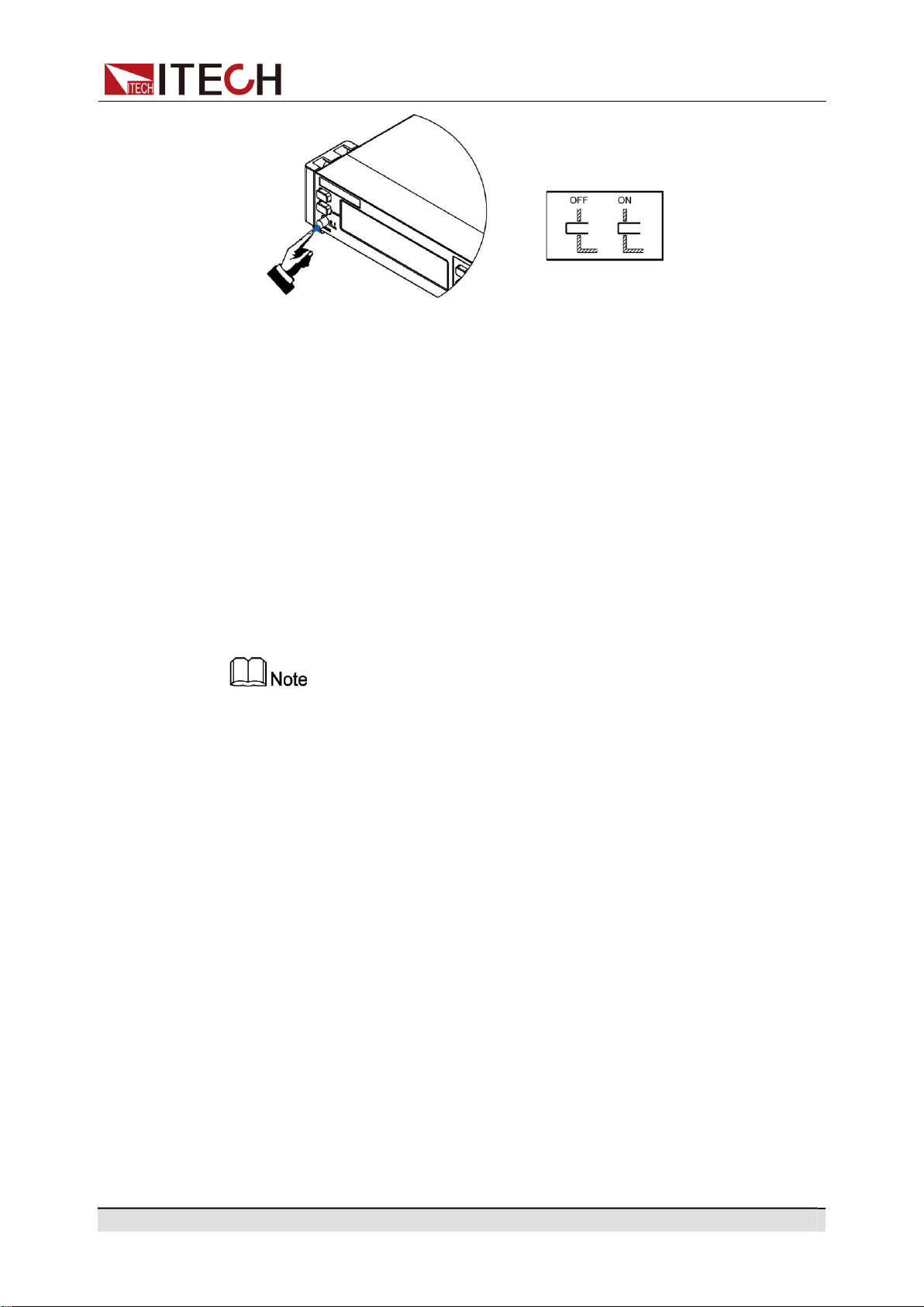
Copyright © Itech Electronic Co., Ltd.
36
Getting Started
Turning the POWER Switch On
Check that the power cord is connected properly.
Turn the unit on with the front panel power switch. The front panel display will
light up after a few seconds. A power-on self-test occurs automatically when
you turn the unit on. This test assures you that the power source is operational.
If a self-test error occurs, an error message will be displayed in the front panel.
Press the [Esc] button to try to clear the current fault status. The user can also
restart the instrument to try to clear the fault status. Wait until the power is
turned off and then start again. If the problem still cannot be solved after restart-
ing, please contact the ITECH engineer. Please refer to Error information list for
detailed information about common error messages.
•
It may take about 30 seconds or so for the power source to initialize before it is
ready for use.
•
When you turn the POWER switch on for the first time after purchase, the instru-
ment starts with its factory default settings. Each time thereafter, the instrument
starts according to the setting that you selected as outlined in 4.9.5 Set the
Power-on State.
Turning the POWER Switch Off
Turn the unit off with the front panel power switch. When it is turned off, the in-
strument interface will prompt “AC Power Off”.
After you turn the POWER switch off, wait at least 10 seconds after the fan
stops before you turn the POWER switch back on. Turning the instrument on
too soon after you turn it off can cause damage to the inrush current limiter cir-
cuit, as well as reduce the life of components such as the POWER switch and
the internal input fuses.

Copyright © Itech Electronic Co., Ltd.
37
Getting Started
3.2
Applying DC Output
The IT-M7700 can be used as a DC power supply. In the following process, the
IT-M7700 is configured as a DC power supply and outputs 20V voltage.
1.
Press the [DC] key to set the instrument to DC output mode.
10.0V 2.00A
0.00W DC MODE
2.
Setting the Source value (voltage output value).
a.
Press [V-set] key to position the cursor to the voltage setting value.
Meanwhile, the [V-set] key will light up.
10.0V 2.00A
0.00W DC MODE
b.
Rotate the knob clockwise to increase the voltage setting value and anti-
clockwise to decrease the value. Set the required value. When setting
the negative voltage value, rotate the current voltage setting value anti-
clockwise to 0, and then continue to rotate anticlockwise to the negative
voltage value.
The knob can be used together with the left/right navigation keys. Press
the left/right navigation keys to move the cursor to a digit. Rotate the
knob to change the digit value.
c.
Press [Enter] key to confirm the voltage setting value.
Press [Esc] key to exit the input mode.
3.
Setting the Limit value (current limit point).
a.
Press the composite keys [Shift]+[F-set](Protect) to enter Protect menu
interface.
1:OVP(rms) = 300.00V
2:OVP(peak) = 440.00V
b.
Rotate the knob to select MCL and press [Enter] key to confirm.
8:MCL =
20.0A
9:Sense Check = Off
c.
Rotate the knob to adjust the max current limit and press [Enter] key to
confirm.
If the input process suspends for more than 5 seconds, the input mode
will be automatically exited. If you want to abandon input, please press
[Esc] key to exit.
d.
Press [Esc] to exit the protection menu setting.
4.
Enable the Output.
Press [On/Off] key to enable the instrument output. When the Output is in
On status, the Output [On/Off] key will light up; when the Output is in Off sta-
tus, the Output [On/Off] will light off.
5.
Checking the Meter values of voltage, current, and power.
After the Output is enabled, the instrument will continuously measure and
display the Meter values of voltage, current, and power on the front panel.

Copyright © Itech Electronic Co., Ltd.
38
Getting Started
20.1V 0.08A
1.68W DC MODE
When the power supply is used as a DC power supply, please understand
the related ripple parameters for this instrument when served as a DC power
supply. If there are strict noise requirements, it is necessary to add additional
DC noise filter to obtain low noise and good and stable DC voltage for test.
3.3
Applying Waveform Output
IT-M7700 can be used as a waveform generator. In the following process, IT-
M7700 is configured as a waveform generator and outputs 10V/50Hz Sine
wave.
1.
Press the [AC] key to set the instrument to AC output mode.
50.0V
6.00A
60.0Hz
0.00W
0.00Ip
0.00PF
2.
Set the AC Voltage.
a.
Press [V-set] key to position the cursor to the voltage setting value.
50.0V
6.00A
60.0Hz
0.00W
0.00Ip
0.00PF
b.
Rotate the knob clockwise to increase the voltage setting value and anti-
clockwise to decrease the value. Set the required value.
The knob can be used together with the left/right navigation keys. Press
the left/right navigation keys to move the cursor to a digit. Rotate the
knob to change the digit value.
c.
Press [Enter] key to confirm the voltage setting value.
Press [Esc] key to exit the input mode.
3.
Set the AC Frequency.
a.
Press [F-set] key to position the cursor to the frequency setting value.
10.0V
6.00A
60.0Hz
0.00W
0.00Ip
0.00PF
b.
Rotate the knob clockwise to increase the frequency setting value and
anticlockwise to decrease the value. Set the required value.
The knob can be used together with the left/right navigation keys. Press
the left/right navigation keys to move the cursor to a digit. Rotate the
knob to change the digit value.
c.
Press [Enter] key to confirm the frequency setting value.
Press [Esc] key to exit the input mode.
4.
Set the AC Phase Angle.
a.
Press the composite keys [Shift]+[V-set](Config) to enter into the config-
uration menu interface.

Copyright © Itech Electronic Co., Ltd.
39
Getting Started
1:I Range = Auto
2:AC + DC = Off
b.
Rotate the knob to select On Phase and press [Enter] key to confirm.
3:On Phase = 0.0°
4:Off Phase = 0.0°
c.
Use left and right keys and rotate the knob to set the starting phase an-
gle. Press [Enter] key to confirm.
If the input process suspends for more than 5 seconds, the input mode
will be automatically exited. If you want to abandon input, please press
[Esc] key to exit.
d.
Rotate the knob to select Off Phase and press [Enter] key to confirm.
4:Off Phase = 0.0°
6:Wave = Sine
e.
Use left and right keys and rotate the knob to set the ending phase angle.
Press [Enter] key to confirm.
If the input process suspends for more than 5 seconds, the input mode
will be automatically exited. If you want to abandon input, please press
[Esc] key to exit.
5.
Select the Output Waveform.
a.
In the Config menu page, rotate the knob to select Wave and press
[Enter] to enter the setting page.
6:Wave = Sine
7: --EXIT--
b.
Rotate the knob to select Sine and press [Enter] key to confirm.
If the input process suspends for more than 5 seconds, the input mode
will be automatically exited. If you want to abandon input, please press
[Esc] key to exit.
c.
Press [Esc] to exit the configuration menu setting.
6.
Setting the Limit value (current limit point).
a.
Press the composite keys [Shift]+[F-set](Protect) to enter Protect menu
interface.
1:OVP(rms) = 300.00V
2:OVP(peak) = 440.00V
b.
Rotate the knob to select MCL and press [Enter] key to confirm.
8:MCL = 20.0A
9:Sense Check = Off
c.
Rotate the knob to adjust the max current limit and press [Enter] key to
confirm.
If the input process suspends for more than 5 seconds, the input mode
will be automatically exited. If you want to abandon input, please press
[Esc] key to exit.
d.
Press [Esc] to exit the protection menu setting.
7.
Enable the Output.

Copyright © Itech Electronic Co., Ltd.
40
Getting Started
Press [On/Off] key to enable the instrument output. When the Output is in
On status, the Output [On/Off] key will light up; when the Output is in Off sta-
tus, the Output [On/Off] will light off.
8.
Check the Meter value of the instrument.
After the output is enabled, the instrument will continuously measure and
display the Meter values of Vrms, Irms, Freq, Ip, PF, Q, P, S, vTHD, and
iTHD on the front panel.
10.03V 0.0005A
50.0Hz
0.00W 0.0056Ip
1.00PF
Press the [Select] key to switch the display of Meter value.
10.03V 0.0005A Q= 0.0
0.00W 0.0VA vTHD=1.02

Copyright © Itech Electronic Co., Ltd.
41
Operation and Application
4 Operation and Application
This chapter describes the operation and application of the instrument in
details.
Select the Output Mode
Set the AC Output
Set the DC Output
Set the Over-current Protection Point
Turning the Output On and Off
Executing Measurement
Function Operation
Protection Function
System-Related Operations
External Analog Quantity Function (Option)
4.1
Select the Output Mode
The IT-M7700 series power supply has 3 output modes: AC, DC and AC+DC.
The User should set specific output mode based on required applications.
AC Mode
This mode is the default mode when the instrument is powered on (It is neces-
sary to press [AC] key to switch the DC mode back to the AC mode), indicating
that the instrument is used as AC power supply. Under this mode, the instru-
ment will generate AC output.
Please refer to 4.2 Set the AC Output for the setting of related output parame-
ters of the instrument under AC mode.
DC Mode
Press [DC] key on the front panel to switch the instrument from AC mode to DC
mode. At this moment, the instrument serves as a DC power supply. Under this
mode, the instrument will generate DC output.
Please refer to 4.3 Set the DC Output for the setting of related output parame-
ters of the instrument under DC mode.

Copyright © Itech Electronic Co., Ltd.
42
Operation and Application
AC+DC Mode
When the AC+DC is turned on, it indicates that the instrument serves as an AC/
DC power supply. Under this mode, the instrument will stack DC voltage compo-
nents based on the generated AC voltage. The turning-on method is as shown
below:
1.
Press the composite keys [Shift] + [V-set](Config) to enter into the configu-
ration menu interface.
2.
Rotate the knob to select AC+DC and press [Enter] key to confirm.
3.
Rotate the knob to switch On and Off options. After selecting On, press
[Enter] key to confirm.
•
On: indicates that the AC+DC output mode is turned on.
•
Off: default value, indicates that the AC+DC output mode is turned off.
4.
Press [Esc] to exit the configuration menu setting.
The related output parameters of the instrument under the AC+DC mode must
be configured under the AC and DC mode independently. Please refer to 4.2
Set the AC Output and 4.3 Set the DC Output.
When the instrument Output is On, it is unable to switch the AC and DC out-
put mode. Only when the instrument Output is Off, you can switch the output
mode by pressing the [AC] and [DC] key.
4.2
Set the AC Output
You can set the voltage, frequency, starting/ending phase angle and waveform
type of the AC output. Before operating the AC output, please select the AC out-
put mode.
4.2.1
Set the AC Voltage
The setting range of AC voltage setting value is between 0V and full-scale rated
output voltage, which is limited by Vac-Max and Vac-Min, i.e., the Vac setting
value should not be higher than Vac-Max and not lower than Vac-Min. Please
refer to 4.8.9 Limiting the Setting Value Range for the setting of Vac-Max and
Vac-Min.
To set Vac, refer to the steps below:
1.
Press the [AC] key to set the instrument to AC output mode.
2.
Press [V-set] key to position the cursor to the voltage setting value. Mean-
while, the [V-set] key will light up.
50.0V 6.00A 60.0Hz

Copyright © Itech Electronic Co., Ltd.
43
Operation and Application
0.00W 0.00Ip 0.00PF
3.
Rotate the knob clockwise to increase the voltage setting value and anti-
clockwise to decrease the value. Set the required value.
The knob can be used together with the left/right navigation keys. Press the
left/right navigation keys to move the cursor to a digit. Rotate the knob to
change the digit value.
4.
Press [Enter] key to confirm the voltage setting value.
Press [Esc] key to exit the input mode.
4.2.2
Set the AC Frequency
The setting range of AC frequency setting value is between 45.0Hz and
1000.0Hz, which is limited by Freq-Max and Freq-Min, i.e., the Freq setting val-
ue should not be higher than Freq-Max and not lower than Freq-Min. Please re-
fer to 4.8.9 Limiting the Setting Value Range for the setting of Freq-Max and
Freq-Min.
To set Freq, refer to the steps below:
1.
Press the [AC] key to set the instrument to AC output mode.
2.
Press [F-set] key to position the cursor to the frequency setting value. Mean-
while, the [F-set] key will light up.
10.0V 6.00A 60.0Hz
0.00W 0.00Ip 0.00PF
3.
Rotate the knob clockwise to increase the frequency setting value and anti-
clockwise to decrease the value. Set the required value.
The knob can be used together with the left/right navigation keys. Press the
left/right navigation keys to move the cursor to a digit. Rotate the knob to
change the digit value.
4.
Press [Enter] key to confirm the frequency setting value.
Press [Esc] key to exit the input mode.
4.2.3
Set the AC Phase Angle
IT-M7700 series supports the initial phase and stop phase of the output wave-
form settable to meet different test requirements. The initial phase and stop
phase are set in the range of 0.0°~359.9°. By adjusting the phase angle, the
user can test the rush current of the product at different positions which is widely
applied to various switch current impulse tests and various rectifiers test. The
setting steps are as follows:
1.
Press the composite keys [Shift] + [V-set](Config) to enter into the configu-
ration menu interface.
2.
Rotate the knob to select On Phase and press [Enter] key to confirm.

Copyright © Itech Electronic Co., Ltd.
44
Operation and Application
3.
Use left and right keys and rotate the knob to set the starting phase angle.
Press [Enter] key to confirm.
4.
Rotate the knob to select Off Phase and press [Enter] key to confirm.
5.
Use left and right keys and rotate the knob to set the ending phase angle.
Press [Enter] key to confirm.
6.
Press [Esc] to exit the configuration menu setting.
4.2.4
Select the Output Waveform
The user can select the type of output waveform for this power supply, includ-
ing: sine wave, square wave, triangle wave, saw wave, clip sine wave,
THD1~THD30 wave, and USER1~USER5 wave. The setting steps are as
follows:
1.
Press the composite keys [Shift] + [V-set](Config) to enter into the configu-
ration menu interface.
2.
Rotate the knob to select Wave and press [Enter] key to confirm.
3.
Rotate the knob to switch the display of various waveform items. After se-
lecting one waveform, press [Enter] key to confirm.
•
Sine: Sinusoidal
•
Square:
•
Triangle
•
Saw: Sawtooth
•
Clip Sine: Clipped Sinusoidal
•
THD1~THD30: 30 sets of built-in waveforms.
•
USER1~USER5: 5 sets of user-defined waveforms.
4.
When the Clip Sine output waveform is selected, you can set the clipped
percentage.
a.
Rotate the knob to select Clip Level and press [Enter] key to enter the
setting page.
b.
Use left and right keys and rotate the knob to set the clipped percentage.
Press [Enter] key to confirm.
5.
Press [Esc] to exit the configuration menu setting.
•
The user-defined waveforms need to be defined in and downloaded from the re-
mote PC. Refer to the IT-M7700 Series Software User Manual for operation
methods.
•
Refer to A.2 Built -in Waveforms for detailed built-in THD waveforms.
•
IT-M7721L/IT-M7722L only supports sine waveform.

Copyright © Itech Electronic Co., Ltd.
45
Operation and Application
4.3
Set the DC Output
You can set the voltage and voltage rise time for the DC output. Before operat-
ing the DC output, please select the DC output mode.
4.3.1
Set the DC Voltage
The setting range of DC voltage setting value is between 0V and full-scale rated
output voltage, which is limited by Vdc-Max and Vdc-Min, i.e., the Vdc setting
value should not be higher than Vdc-Max and not lower than Vdc-Min. Please
refer to 4.8.9 Limiting the Setting Value Range for the setting of Vdc-Max and
Vdc-Min.
To set Vdc, refer to the steps below:
1.
Press the [DC] key to set the instrument to DC output mode.
2.
Press [V-set] key to position the cursor to the voltage setting value. Mean-
while, the [V-set] key will light up.
10.0V 2.00A
0.00W DC MODE
3.
Rotate the knob clockwise to increase the voltage setting value and anti-
clockwise to decrease the value. Set the required value.
The knob can be used together with the left/right navigation keys. Press the
left/right navigation keys to move the cursor to a digit. Rotate the knob to
change the digit value.
4.
Press [Enter] key to confirm the voltage setting value.
Press [Esc] key to exit the input mode.
When the power supply is used as a DC power supply, please understand
the related ripple parameters for this instrument when served as a DC power
supply. If there are strict noise requirements, it is necessary to add additional
DC noise filter to obtain low noise and good and stable DC voltage for test.
4.3.2
Set the DC Voltage Rise Time
With this power supply, you can set the voltage rise time under the DC mode,
with the setting range of 0ms ~ 99,999ms. 0ms means Off, indicating that the
power supply voltage rises quickly with maximum tolerance. The voltage rise
time means the time when the power supply output voltage reaches the stable
setting value for the first time from zero time. You can set the voltage rise time
on the front panel or through remote control operation. The set voltage rise time
will affect the voltage change speed when the real-time voltage changes. The
setting steps are as follows:

Copyright © Itech Electronic Co., Ltd.
46
Operation and Application
1.
Press the composite keys [Shift] + [V-set](Config) to enter into the configu-
ration menu interface.
2.
Rotate the knob to select V-Rise Time and press [Enter] key to confirm.
3.
Use left and right keys and rotate the knob to set the voltage rise time. Press
[Enter] key to confirm.
4.
Press [Esc] to exit the configuration menu setting.
4.4
Set the Over-current Protection Point
With this instrument, you can directly set the over-current protection point value
for the OCP (rms) function through the [I-set] key. Refer to 4.8.5 Set the Over-
Current Protection (peak) for the related description of OCP (rms).
The setting range of over-current protection point value is between 0A and full-
scale rated output current, which is limited by OCP-Max and OCP-Min, i.e., the
over-current protection point value should not be higher than OCP-Max and not
lower than OCP-Min. Please refer to 4.8.9 Limiting the Setting Value Range for
the setting of OCP-Max and OCP-Min.
To set OCPrms, refer to the steps below:
1.
Press [I-set] key to position the cursor to the OCPrms setting value.
Meanwhile, the [I-set] key will light up.
50.0V 6.00A 60.0Hz
0.00W 0.00Ip 0.00PF
2.
Rotate the knob clockwise to increase the OCPrms setting value and
anticlockwise to decrease the value. Set the required value.
The knob can be used together with the left/right navigation keys. Press the
left/right navigation keys to move the cursor to a digit. Rotate the knob to
change the digit value.
3.
Press [Enter] key to confirm the OCPrms setting value.
Press [Esc] key to exit the input mode.

Copyright © Itech Electronic Co., Ltd.
47
Operation and Application
4.5
Turning the Output On and Off
•
The [On/Off] key light is off and turning the output off does not
place the instrument in a safe state. Hazardous voltages may be
present on all output and guard terminals. Putting the equipment
into an output-off state does not guarantee that the outputs are
powered off if a hardware or software fault occurs. See the cautions
about connecting the DUT before connecting DUT.
•
To prevent electrical shock that could cause injury or death, please
ensure that the power source and DUT have been connected well
before you turn the output on.
•
The [On/Off] key is used to turn the output/input on or off under
normal circumstances. Even if the instrument is in control by PC or
the keyboard is locked, the [On/Off] is still valid.
You can turn the IT-M7700 output on or off from the front panel [On/Off] key.
Press the [On/Off] key, and the key lights up, indicating the real-time output is
On. The Meter value on the interface will display the voltage, current, or power
values of the real-time circuit; press [On/Off] key again, and the key lights off,
indicating that the real-time output is Off.
4.6
Executing Measurement
In this power supply, you can measure actual performance of the output termi-
nal of the power supply without using other measurement instruments. When
the power supply Output is On, it will measure the V, I, F, and P of the output ter-
minal of the power supply. Before executing measurement, the user needs to
set the current measurement range.
4.6.1
Measurement Functions
This power supply provides measurement functions for 12 types of electrical pa-
rameters. All these measurement parameters can be displayed on the main
interface.
•
Under the DC mode, the DC main interface displays all DC measurements:
Vdc, Idc and P.
•
Under the AC mode, the AC main interface 1 displays the following AC
measurements: Vrms, Irms, F, P, Ip, and PF; and the AC main interface 2
displays the following AC measurements: Vrms, Irms, Q、P, S, vTHD and

Copyright © Itech Electronic Co., Ltd.
48
Operation and Application
Function Definition
iTHD. You can use the [Select] key to switch between the AC main interface
1 and the AC main interface 2.
The definitions of the functions are listed in the following table:
AC Mode
Vrms It is the measurement of Voltage effective value.
Irms It is the measurement of Current effective value.
F It is the measurement of Frequency.
P
Active Power.
Ip Current peak-to-peak value.
PF It is the Power Factor, and its calculation formula = P/S.
Q
It is the Reactive Power, and its calculation formula =
.
S It is the Apparent Power, and its calculation formula =
Vrms × Irms。
vTHD Total voltage harmonic distortion factor.
iTHD Total current harmonic distortion factor.
DC Mode
Vdc It is the measurement of DC Voltage.
Idc It is the measurement of DC Current.
P Power.
4.7
Function Operation
4.7.1
List Function
IT-M7700 List mode supports program complex waveform editing. The users
can edite 5 list files (List1 to List5) , each file can be edited up to 50 steps. Each
step settable parameters include: basic waveform (incl. THD and user defined
waveform), AC/DC amplitude, slew rate, frequency, dwell time, start/stop phase
angle, times of repetition etc. This function with complex waveforms can help
users to simulate grid disturbance, periodic power off and so on.

Copyright © Itech Electronic Co., Ltd.
49
Operation and Application
This power supply needs to use the IT-M7700 Series Software to edit the List
function contents, and download the List files to local equipment. Then, the in-
strument can locally run the List function. The user can also run all functions of
the List in the IT- M7700 Series Software.
Operation Steps:
1.
Edit List Program.
Please refer to “Edit List File” or “Export/Import List in PC” in the IT-M7700
Series Software User Manual to edit the List file.
2.
Set the List mode.
a.
Press the composite keys [Shift] + [I-set](Function) to enter function
menu interface.
1:List Mode = Off
2:List Trigger = On
b.
Rotate the knob to select List Mode and press [Enter] key to confirm.
c.
Rotate the knob to select the name of the List file to be run and press
[Enter] key to confirm.
•
Off: Default value, indicating that the List Mode function is disabled.
•
1: indicate that the List Mode function is enabled, and List 1 file is
called.
•
2: indicate that the List Mode function is enabled, and List 2 file is
called.
•
3: indicate that the List Mode function is enabled, and List 3 file is
called.
•
4: indicate that the List Mode function is enabled, and List 4 file is
called.
•
5: indicate that the List Mode function is enabled, and List 5 file is
called.
3.
Set the trigger mode to run the List.
a.
Select List Trigger in the Function menu interface and press [Enter] key
to confirm.
b.
Rotate the knob to switch On and Off options. After selecting On or Off,
press [Enter] key to confirm.
•
Off: After the Trigger key is pressed, the instrument will automatically
run the real-time List file.
•
On: After the Trigger key is pressed, the instrument will run the real-
time List file in single step.
c.
Press [Esc] to exit the function menu setting.
4.
Press the [On/Off] key to turn on the instrument output.
50.0V 3.00A
50.0Hz
List 5 Step 0/ 7 Stop
5.
Press the composite keys [Shift] + [On/Off](Trigger) on the front panel to
run the selected List file.
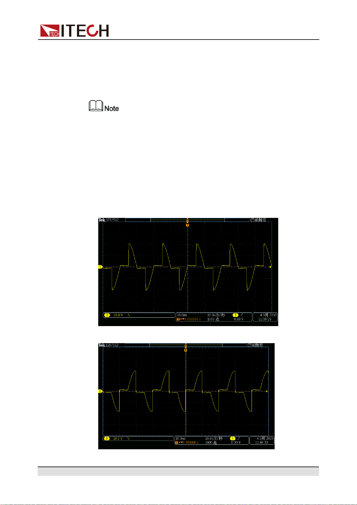
Copyright © Itech Electronic Co., Ltd.
50
Operation and Application
50.0V 3.00A
50.0Hz
List 5 Step 1/ 7
Run
•
When List Trigger = On, press the Trigger key once, and the instrument
will run one step of List output.
•
When List Trigger = Off, the instrument will output based on defined List.
IT-M7721L/IT-M7722L do not support list function.
4.7.2
Dimmer Function
The Dimmer Function aims to adjust the light illuminance intensity by setting the
phase angle and concealing the leading edge or trailing edge waveform. This
IT-M7700 series power supply supports front and rear phase angle dimmer or
speed adjustment test to verify whether the product has potential quality prob-
lem when the end user uses dimmer or the speed controller.
•
Dimmer of leading edge
•
Dimmer of trailing edge

Copyright © Itech Electronic Co., Ltd.
51
Operation and Application
1.
Press the [AC] key to set the instrument to AC output mode.
2.
Refer to 4.2 Set the AC Output to set parameters related to basic Sine
waveform.
3.
Enable the phase dimmer function.
a.
Press the composite keys [Shift] + [I-set](Function) to enter function
menu interface.
b.
Rotate the knob to select Dimmer and press [Enter] key to confirm.
c.
Rotate the knob to switch the display among Off, LeadingEdge and
TrailingEdge . After selecting LeadingEdge or TrailingEdge , press
[Enter] key to confirm.
•
Off: Default value, indicating that the Dimmer function is disabled.
•
LeadingEdge: indicate that the Leading Edge Dimmer function is
enabled.
•
TrailingEdge: indicate that the Trailing Edge Dimmer function is
enabled.
4.
Set the dimmer phase angle.
a.
Rotate the knob and select the Dimmer Phase. Press [Enter] key to set
the dimmer phase angle.
b.
Press [Esc] to exit the function menu setting.
5.
Press [On/Off] key, and the power supply outputs the set phase dimmer
waveform. Press[On/Off] again to stop output.
10.0V 3.00A 45.0Hz
Phase= 90.0° TrailingEdge
•
The phase dimmer function can only be used under the AC Mode.
•
IT-M7721L/IT-M7722L do not support dimmer function.
4.7.3
Surge/Trap Function
IT-M7700 provides surge/trap simulation. The user can add surge/trap to simu-
late abnormal voltage fluctuation on the basis of outputting Sin wave, and test
usage of the DUT under this circumstance. The descriptions of surge/trap menu
are listed in the table below.
Surge Trap
Surge/trap function.
Off
Turn the surge/trap function off.
On
Turn the surge/trap function on.
Period
Set the period of the surge/trap.

Copyright © Itech Electronic Co., Ltd.
52
Operation and Application
Width
Set the surge/trap width.
Percent
Set the percentage of the surge/
trap amplitude to AC signal ampli-
tude (rms).
Operation Steps:
1.
Press the [AC] key to set the instrument to AC output mode.
2.
Refer to 4.2 Set the AC Output to set parameters related to basic Sine
waveform.
3.
Turn the surge/trap function on.
a.
Press the composite keys [Shift] + [I-set](Function) to enter function
menu interface.
b.
Rotate the knob to select Surge Trap and press [Enter] key to confirm.
c.
Rotate the knob to switch On and Off options. After selecting On, press
[Enter] to turn on the glitch/notch function.
4.
Set the parameters of the surge/trap.
a.
Rotate the knob to select Period and press [Enter] key to set the period
of the surge/trap.
b.
Rotate the knob to select Width and press [Enter] key to set the width of
the surge/trap.
c.
Rotate the knob to select Percent and press [Enter] key to set the per-
centage of the surge/trap.
d.
Press [Esc] to exit the function menu setting.
5.
Press [On/Off] key, and the power supply outputs the set surge/trap wave-
form. Press[On/Off] again to stop output.
10.0V
3.00A
50.0Hz
1Cycle
1.00mS
30.0%
Waveform Example
•
The trap diagram when Period=2Cycle, Width=1.00mS, and Percent=30% is
as follows:
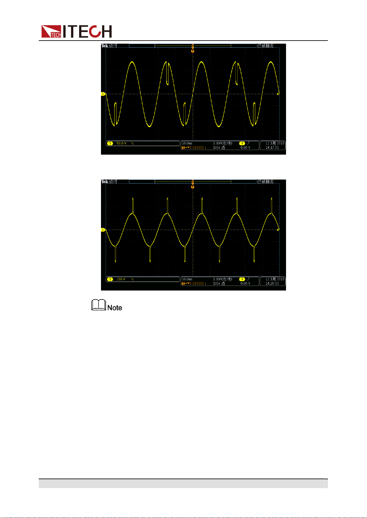
Copyright © Itech Electronic Co., Ltd.
53
Operation and Application
•
The surge diagram when Period=1Cycle, Width=0.4mS, and Percent=200%
is as follows:
•
The surge/trap function can only be used under the AC Mode.
•
IT-M7721L/IT-M7722L do not support surge/trap function.
4.8
Protection Function
4.8.1
Set the Over-Voltage Protection (rms)
The user can set the over-voltage protection point for the over-voltage protec-
tion (rms) function. When the output voltage reaches the over-voltage protection
point, the over-voltage protection (rms) will turn off the output. The function is
mainly used to protect the DUT connected during test to prevent it from damage
due to over-voltage. The OVP (rms) function is always enabled.

Copyright © Itech Electronic Co., Ltd.
54
Operation and Application
Set the OVP(rms) point
1.
Press the composite keys [Shift] + [F-set](Protect) to enter Protect menu
interface.
2.
Rotate the knob to select OVP(rms) and press [Enter] key to confirm.
3.
Rotate the knob to adjust the OVP(rms) point and press [Enter] key to
confirm.
4.
Press [Esc] to exit the protection menu setting.
Clear OVP(rms) status
When over-voltage protection occurs, the instrument responds as follows:
•
The instrument output is turned off, and other keys (except the [Esc] key)
are locked.
•
The buzzer sounds intermittently three times: one long beep and two short
beeps.
•
The interface displays “OVPrms Occurred!!”;
•
Status register, the OVPrms status bit is set to 1.
To clear the over-voltage and return to normal operation, firstly remove the con-
ditions that caused the protection fault. Press [Esc] key (or send the command
PROTect:CLEar) to clear the protection status. The “OVPrms Occurred!!” dis-
played in front panel is cleared and the instrument exits OVP(rms) status.
4.8.2
Set the Over-Voltage Protection (peak)
The user can set the over-voltage protection point for the over-voltage protec-
tion (peak) function. When the output voltage reaches the over-voltage protec-
tion point, the over-voltage protection (peak) will turn off the output. The
function is mainly used to protect the DUT connected during test to prevent it
from damage due to over-voltage. The OVP (peak) function is always enabled.
Set the OVP(peak) point
1.
Press the composite keys [Shift] + [F-set](Protect) to enter Protect menu
interface.
2.
Rotate the knob to select OVP(peak) and press [Enter] key to confirm.
3.
Rotate the knob to adjust the OVP(peak) point and press [Enter] key to
confirm.
4.
Press [Esc] to exit the protection menu setting.
Clear OVP(peak) status
When over-voltage protection occurs, the instrument responds as follows:

Copyright © Itech Electronic Co., Ltd.
55
Operation and Application
•
The instrument output is turned off, and other keys (except the [Esc] key)
are locked.
•
The buzzer sounds intermittently three times: one long beep and two short
beeps.
•
The interface displays “OVPpeak Occurred!!”;
•
Status register, the OVPpeak status bit is set to 1.
To clear the over-voltage and return to normal operation, firstly remove the con-
ditions that caused the protection fault. Press [Esc] key (or send the command
PROTect:CLEar) to clear the protection status. The “OVPpeak Occurred!!” dis-
played in front panel is cleared and the instrument exits OVP(peak) status.
4.8.3
Set the Under-Voltage Protection (rms)
The user can set the under-voltage protection limit for the under-voltage protec-
tion (rms) function. If the output voltage is lower than the under-voltage limit, the
under-voltage protection (rms) will turn off the output. The UVP (rms) functions
is always enabled.
Set the UVP(rms) limit
1.
Press the composite keys [Shift] + [F-set](Protect) to enter Protect menu
interface.
2.
Rotate the knob to select UVP(rms) and press [Enter] key to confirm.
3.
Rotate the knob to adjust the UVP(rms) limit and press [Enter] key to
confirm.
4.
Press [Esc] to exit the protection menu setting.
Clear UVP(rms) status
When under-voltage protection occurs, the instrument responds as follows:
•
The instrument output is turned off, and other keys (except the [Esc] key)
are locked.
•
The buzzer sounds intermittently three times: one long beep and two short
beeps.
•
The interface displays “UVPrms Occurred!!”;
•
Status register, the UVPrms status bit is set to 1.
To clear the under-voltage and return to normal operation, firstly remove the
conditions that caused the protection fault. Press [Esc] key (or send the com-
mand PROTect:CLEar) to clear the protection status. The “UVPrms Occurred!!”
displayed in front panel is cleared and the instrument exits UVP(rms) status.

Copyright © Itech Electronic Co., Ltd.
56
Operation and Application
4.8.4
Set the Over-Current Protection (rms)
The user can set the over-current protection point for the over-current protection
(rms) function. When the output current reaches the over-current protection
point, the over-current protection (rms) will turn off the output. The function is
mainly used to protect the DUT connected during test to prevent it from damage
due to over-current. The OCP (rms) function is always enabled.
Set the OCP(rms) point
1.
Press the composite keys [Shift] + [F-set](Protect) to enter Protect menu
interface.
2.
Rotate the knob to select OCP(rms) and press [Enter] key to confirm.
3.
Rotate the knob to adjust the OCP(rms) point and press [Enter] key to
confirm.
4.
Press [Esc] to exit the protection menu setting.
Set the OCP delay
You can specify an OCP delay to prevent momentary output settings, DUT and
status changes from tripping the over-current protection. In most cases these
momentary conditions would not be considered an over-current protection fault,
and having an OCP condition disable the output when they occur would be a
nuisance. Specifying an OCP delay lets the OCP circuit ignore these momenta-
ry changes during the specified delay period. Once the OCP delay time has ex-
pired and the over-current condition persists, the output will shut down.
1.
Press the composite keys [Shift] + [F-set](Protect) to enter Protect menu
interface.
2.
Rotate the knob to select OCP Delay and press [Enter] key to confirm.
3.
Rotate the knob to adjust the OCP delay time and press [Enter] key to
confirm.
4.
Press [Esc] to exit the protection menu setting.
Clear OCP(rms) status
When over-current protection occurs, the instrument responds as follows:
•
The instrument output is turned off, and other keys (except the [Esc] key)
are locked.
•
The buzzer sounds intermittently three times: one long beep and two short
beeps.
•
The interface displays “OCPrms Occurred!!”;
•
Status register, the OCPrms status bit is set to 1.

Copyright © Itech Electronic Co., Ltd.
57
Operation and Application
To clear the over-current and return to normal operation, firstly remove the con-
ditions that caused the protection fault. Press [Esc] key (or send the command
PROTect:CLEar) to clear the protection status. The “OCPrms Occurred!!” dis-
played in front panel is cleared and the instrument exits OCP status.
4.8.5
Set the Over-Current Protection (peak)
The user can set the over-current protection point for the over-current protection
(peak) function. When the output current reaches the over-current protection
point, the over-current protection (peak) will turn off the output. The function is
mainly used to protect the DUT connected during test to prevent it from damage
due to over-current. The OCP (peak) function is always enabled.
Set the OCP(peak) point
1.
Press the composite keys [Shift] + [F-set](Protect) to enter Protect menu
interface.
2.
Rotate the knob to select OCP(peak) and press [Enter] key to confirm.
3.
Rotate the knob to adjust the OCP(peak) point and press [Enter] key to
confirm.
4.
Press [Esc] to exit the protection menu setting.
Set the OCP delay
You can specify an OCP delay to prevent momentary output settings, DUT and
status changes from tripping the over-current protection. In most cases these
momentary conditions would not be considered an over-current protection fault,
and having an OCP condition disable the output when they occur would be a
nuisance. Specifying an OCP delay lets the OCP circuit ignore these momenta-
ry changes during the specified delay period. Once the OCP delay time has ex-
pired and the over-current condition persists, the output will shut down.
1.
Press the composite keys [Shift] + [F-set](Protect) to enter Protect menu
interface.
2.
Rotate the knob to select OCP Delay and press [Enter] key to confirm.
3.
Rotate the knob to adjust the OCP delay time and press [Enter] key to
confirm.
4.
Press [Esc] to exit the protection menu setting.
Clear OCP(peak) status
When over-current protection occurs, the instrument responds as follows:
•
The instrument output is turned off, and other keys (except the [Esc] key)
are locked.

Copyright © Itech Electronic Co., Ltd.
58
Operation and Application
•
The buzzer sounds intermittently three times: one long beep and two short
beeps.
•
The interface displays “OCPpeak Occurred!!”;
•
Status register, the OCPpeak status bit is set to 1.
To clear the over-current and return to normal operation, firstly remove the con-
ditions that caused the protection fault. Press [Esc] key (or send the command
PROTect:CLEar) to clear the protection status. The “OCPpeak Occurred!!” dis-
played in front panel is cleared and the instrument exits OCP status.
4.8.6
Set the Over-Power Protection
The user can set the over-power protection point for the over-power protection
function. When the output power reaches the over-power protection point, the
over-power protection will turn off the output. The function is mainly used to pro-
tect the DUT connected during test to prevent it from damage due to over-cur-
rent. The OPP function is always enabled.
Set the OPP point
1.
Press the composite keys [Shift] + [F-set](Protect) to enter Protect menu
interface.
2.
Rotate the knob to select OPP and press [Enter] key to confirm.
3.
Rotate the knob to adjust the OPP point and press [Enter] key to confirm.
4.
Press [Esc] to exit the protection menu setting.
Clear OPP status
When over-power protection occurs, the instrument responds as follows:
•
The instrument output is turned off, and other keys (except the [Esc] key)
are locked.
•
The buzzer sounds intermittently three times: one long beep and two short
beeps.
•
The interface displays “OPP Occurred!!”;
•
Status register, the OPP status bit is set to 1.
To clear the over-power and return to normal operation, firstly remove the condi-
tions that caused the protection fault. Press [Esc] key (or send the command
PROTect:CLEar) to clear the protection status. The “OPP Occurred!!” displayed
in front panel is cleared and the instrument exits OPP status.

Copyright © Itech Electronic Co., Ltd.
59
Operation and Application
4.8.7
Set the Current Limiting Protection
The user can set the current limiting point for the current limiting protection func-
tion. If the output current reaches the limiting current protection point, the pro-
tection will be activated. The power supply output current is controlled within the
current limiting value, and the output is stopped after several milliseconds. The
current limiting protection function can limit the instrument output to prevent the
DUT from being damaged. The operation steps are as follows.
1.
Press the composite keys [Shift] + [F-set](Protect) to enter Protect menu
interface.
2.
Rotate the knob to select MCL and press [Enter] key to confirm.
3.
Rotate the knob to adjust the current limiting point, and press [Enter] key to
confirm.
4.
Press [Esc] to exit the protection menu setting.
When the frequency setting is less than or equal to 100Hz, the MCL value
can be adjusted; if the frequency is set above 100Hz, the MCL value will be
locked at 20.0A.
4.8.8
Set the Sense Check Protection
Sense Check protection is a programmable and settable function by users,
which can be enabled or disabled. After this function is enabled, the remote
measurement will be checked before instrument output. If the remote sense ter-
minals (SL+, SN-) are inverted, the protection will be activated and the output
will be stopped. When this function is disabled, the instrument will not check
whether the remote sense terminals have been connected before output. The
operation steps are as follows.
1.
Press the composite keys [Shift] + [F-set](Protect) to enter Protect menu
interface.
2.
Rotate the knob to select Sense Check and press [Enter] key to confirm.
3.
Rotate the knob to switch On and Off options. After selecting On or Off,
press [Enter] key to confirm.
•
Off: Default value, indicating that the Sense Check protection is disabled.
•
On: indicate that the Sense Check protection is enabled.
4.
Press [Esc] to exit the protection menu setting.
When the Sense Check protection occurs, the power supply output will be
turned off. The user needs to check the wiring of the SL+ and SN- terminals on
the rear panel to remove abnormalities.

Copyright © Itech Electronic Co., Ltd.
60
Operation and Application
4.8.9
Limiting the Setting Value Range
All setting values (Vac, Vdc, Freq, OCPrms) can be adjusted between 0 and
100%. You can reset the upper and lower limits of all setting values in the
Protect menu. After setting the limiting values, the setting values of Vac, Vdc,
Freq, OCPrms can only be set within the upper and lower limit ranges. The
operation steps are as follows.
1.
Press the composite keys [Shift] + [F-set](Protect) to enter Protect menu
interface.
2.
Rotate the knob to select Range Set and press [Enter] key to confirm.
3.
Rotate the knob to switch the display of maximum value/minimum value
options of setting values like Vac, Vdc, Freq and OCPrms. Select one item
and press [Enter] key to confirm.
•
Vac-Max: set the maximum value of the AC voltage setting value.
•
Vac-Min: set the minimum value of the AC voltage setting value.
•
Vdc-Max: set the maximum value of the DC voltage setting value.
•
Vdc-Min: set the minimum value of the DC voltage setting value.
•
Freq-Max: set the maximum value of the frequency setting value.
•
Freq-Min: set the minimum value of the frequency setting value.
•
OCP-Max: set the maximum value of the OCPrms setting value.
•
OCP-Min: set the minimum value of the OCPrms setting value.
4.
Rotate the knob to adjust the parameter, and press [Enter] key to confirm.
5.
Press [Esc] to exit the protection menu setting.
4.9
System-Related Operations
4.9.1
Switch Local/Remote Mode
IT-M7700 series power source provide local operation and remote operation.
The default mode is local operation mode.
•
Local operation mode: use front panel keys to control the power source.
•
Remote operation mode: the power source is connected to PC, the user
uses the software in PC to control the power source remotely. During remote
control operation, the[Enter] key on the front panel is lit. All panel keys, ex-
cept the [On/Off] and [Shift] + [Link](Local) keys, are locked. You can
press[Shift] + [Link](Local) to switch the remote control to local control. The
mode modification will not affect the output parameters.

Copyright © Itech Electronic Co., Ltd.
61
Operation and Application
4.9.2
Save and Recall Operations
IT-M7700 series power source can save up to 10 common parameters in nonvo-
latile memory (No. 0 to No. 9) for user to recall conveniently. The contents
stored in each group include: output mode(AC/DC), voltage setting value(AC),
voltage setting value(DC), OCPrms, frequency setting value and phase angle.
Save Operations
1.
Press the composite keys [Shift] + (Save) to enter the parameter save
interface.
110.0V 1.00A 60.0Hz
Save data bank = 0
Information description:
•
The first line displays the content to be saved, i.e., the real-time setting
value.
•
The second line displays the setting value of the saved position.
2.
Rotate the knob and input the digits 0~9 to set the saved position.
3.
Press the [Enter] key to save the real-time setting value.
Recall Operations
1.
Press the composite keys [Shift] + (Recall) to enter the parameter re-
call interface.
5.00V 6.00A DC MODE
Recall data bank =3
Information description:
•
The first line displays the content to be recalled
•
The second line displays the setting value of the recalled position.
2.
Rotate the knob and input the digits 0~9 to set the recalled position.
3.
Press the [Enter] key to call the contents in the memory to use as the real-
time setting values.
4.9.3
Key Lock Function
The front panel controls can be locked to protect from accidental power source
parameter change. Press the composite keys[Shift] + [Enter] (Lock) to lock
front panel keys and the [Enter] key is lit. All panel keys, except the [On/Off]
and [Shift] + [Enter] (Lock) keys, are locked. You can repress [Shift] + [Enter]
(Lock) to unlock the front panel.

Copyright © Itech Electronic Co., Ltd.
62
Operation and Application
Parameter Fixed Value
4.9.4
Set the Beeper Status
This item can set the buzzer state.
Operation Steps:
1.
Press the composite keys [Shift] + [DC](System) to enter into the system
menu interface.
2.
Rotate the knob to select Beep and press [Enter] key to confirm.
3.
Rotate the knob to switch On and Off options. After selecting On or Off,
press [Enter] key to confirm.
•
On: default value, indicates the beeper is on.
•
Off: indicates the beeper is off.
4.
Press [Esc] to exit the system menu setting.
At this point, the beeper sound operation immediately becomes valid.
4.9.5
Set the Power-on State
This menu item is used to control the settings and output state when the power
source is powered on. The detailed power-on parameters and output state are
as follows.
•
Output mode(AC/DC), AC voltage setting value, DC voltage setting value,
OCPrms and frequency setting value.
•
The output state of the power source, i.e., the [On/Off] key state.
Operation Steps:
1.
Press the composite keys [Shift] + [DC](System) to enter into the system
menu interface.
2.
Rotate the knob to select PowerOn and press [Enter] key to confirm.
3.
Rotate the knob to set the power-on state and press [Enter] key to confirm.
•
Reset: default value, indicates that the power source recalls the fixed set-
tings at power-on. For details about the fixed settings of the instrument
are as shown in the following table.
Table 4–1 Fixed value of the parameter
Vac 50V
Vdc 0V
OCP Max
Freq 50.0Hz
AC + DC Off

Copyright © Itech Electronic Co., Ltd.
63
Operation and Application
Parameter Factory default value
Output Mode AC
[On/Off] status Off
•
Last: indicates when powered on, the power source will remain the same
settings and output state as last time you turned off the power source.
•
Last+Off: indicates when powered on, the power source will remain the
same settings as last time you turned off the power source, but the output
state is Off state.
4.
Press [Esc] to exit the system menu setting.
4.9.6
Restore the as-shipped settings
This menu item is used to restore the as-shipped settings. The procedures to
set the menu item are as follows.
1.
Press the composite keys [Shift] + [DC](System) to enter into the system
menu interface.
2.
Rotate the knob to select System Reset and press [Enter] key to confirm.
3.
Rotate the knob to switch Yes and No options. After selecting Yes or No,
press [Enter] key to confirm.
•
No: default value, indicates the power source cancels this menu setting.
•
Yes: indicates the power source restores the as-shipped settings.
4.
Press [Esc] to exit the system menu setting.
Table 4–2 The as-shipped settings
Source
Vac 50V
Vdc 0V
OCPrms 6A
Freq 50.0Hz
Config menu
I Range Auto
AC + DC Off
On Phase 0.0°
Off Phase 0.0°
Parameter Fixed Value

Copyright © Itech Electronic Co., Ltd.
64
Operation and Application
V-Rise Time Off
Wave Sine
System menu
Beep On
PowerOn Last+Off
CAN Address 1
CAN Baudrate 500K
IP Mode Auto
IP 192.168.0.2
Gate 192.168.0.1
Mask 255.255.255.0
DNS1 0.0.0.0
DNS2 0.0.0.0
Port 30000
GPIB Address 1
RS232 Baudrate 115200
Relay Ctrl Out Syn
System Reset
No
Protect menu
OVP(rms)
440.0V
OVP(peak)
440.00V
UVP(rms)
0.0V
OCP(rms)
6.00A
OCP(peak)
20.00A
OCP delay
50ms
OPP 600.00VA
MCL 20.0A
Sense Check Off
Vac-Max 300.0V
Parameter Factory default value

Copyright © Itech Electronic Co., Ltd.
65
Operation and Application
Name Description
Vac-Min 0.0V
Vdc-Max 400.0V
Vdc-Min -400.0V
Freq-Max
1000.0Hz
Freq-Min
45.0Hz
OCP-Max 6.10A
OCP-Min 0.00A
Function menu
List Mode Off
List Trigger
Off
Dimmer Off
Surge Trap Off
4.9.7
View the System Information
This menu item is used to view the system information of the instrument. The
procedures to view the system information are as follows.
1.
Press the composite keys [Shift] + [DC](System) to enter into the system
menu interface.
2.
Rotate the knob to select System Info and press [Enter] key to confirm.
3.
Rotate the knob to page up and down and check the instrument system in-
formation. Specific parameters are shown in the table below:
Manufacturer Display the manufacturer's name.
Model Display the instrument model.
Version Display the software version.
Serial Number Display the serial number.
SCPI Error Display SCPI command error
information.
Last Cal. Date Display last calibration date.
4.
Press [Esc] to exit the system menu setting.
Parameter Factory default value

Copyright © Itech Electronic Co., Ltd.
66
Operation and Application
4.9.8
Set the Relay Control
The power output has a built-in relay used for connecting the load, which can
realize electrical isolation between the power end and the load end.
•
When the output relay is set to NC, it indicates that the relay will be normally
closed in regardless of whether the power supply’s output status is Off or
not, i.e., accessing to the load circuit.
•
When the output relay is set to Out Syn, it indicates that the relay will be
closed only when the output status is On; if the output status is Off, the out-
put relay will be open, i.e., isolating the load circuit.
Operation Steps:
1.
Press the composite keys [Shift] + [DC](System) to enter into the system
menu interface.
2.
Rotate the knob to select Relay Ctrl and press [Enter] key to confirm.
3.
Rotate the knob to switch Out Syn and NC options. After selecting Out Syn
or NC, press [Enter] key to confirm.
•
Out Syn: The relay is linked with Output. When the instrument output is
On, the relay is closed; when the instrument output is Off, the relay is
open, and the instrument and the load are electrically separated.
•
NC: The relay is normally closed. Whether the instrument out is On or Off
will not affect the operation of relay.
4.
Press [Esc] to exit the system menu setting.
4.10
External Analog Quantity Function (Option)
IT-M7700 series power supply provides a optional DB25 analog interface(IT-
E1208). The analog interface provides the following capability:
•
Remote control of output voltage and current.
•
Remote control of output On/Off state.
•
Remote monitoring of output voltage/current measurement and AC/DC
mode.
•
Clear the instrument error status.
•
Remote monitoring of output On/Off state, load status and error status.
4.10.1
Definition of Analog Interface
Analog signal bandwidth is less than 100 Hz, supports any waveform within sig-
nal bandwidth. When the program signal frequency or amplitude exceeds output
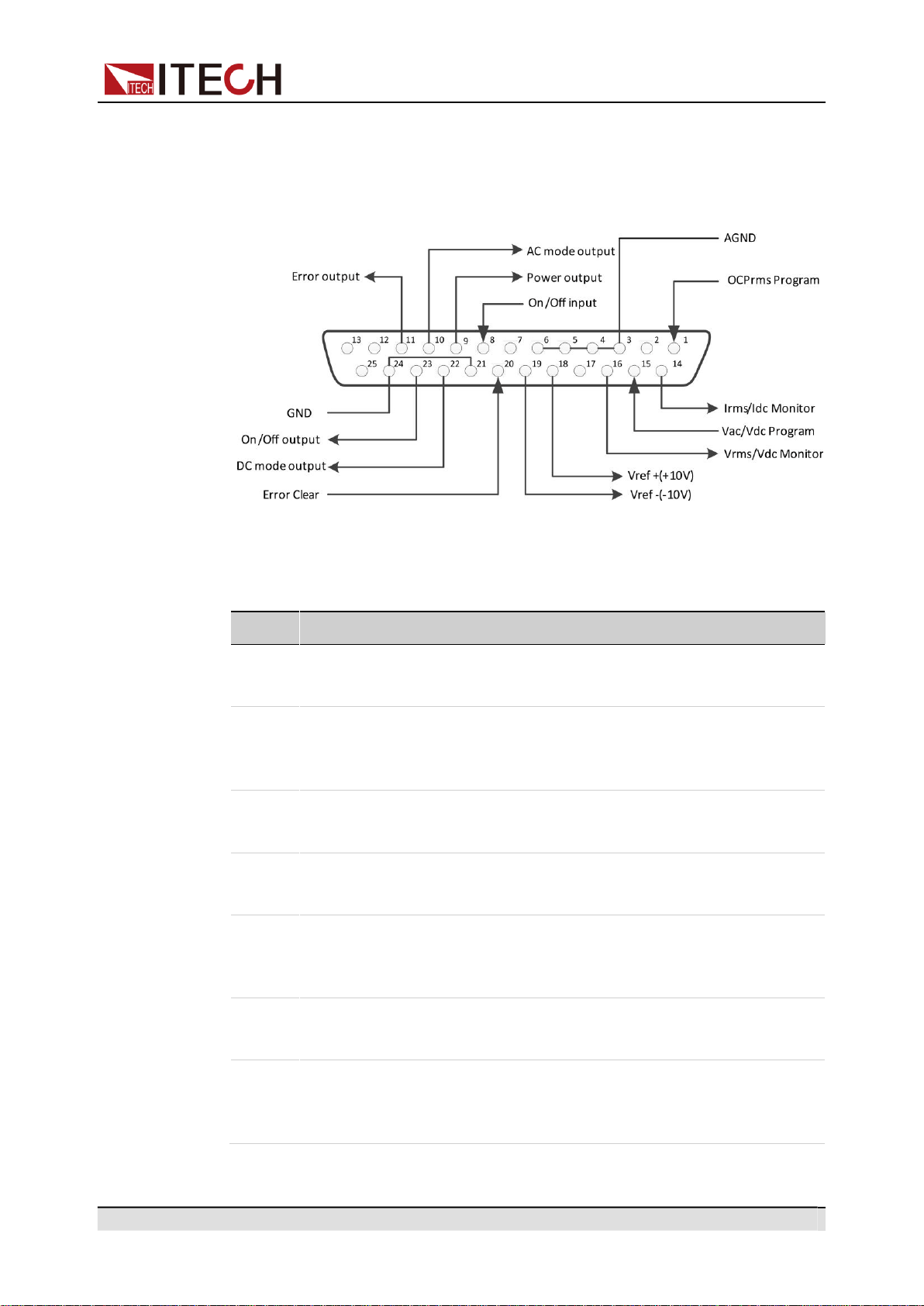
Copyright © Itech Electronic Co., Ltd.
67
Operation and Application
capacity, the output amplitude will be automatically limited. The definitions and
descriptions for analog interface are as follows.
Figure 4–1 DB25 Analog Interface
Table 4–3 Description of DB25 Analog Interface
Pin
Name
Type
Description
1
OCPrms
Analog in
Programs OCPrms.
Program
2/7/12/
Not used
-
-
13/17/
25
3/4/5/6
AGND
Ground
Ground for analog inputs and
outputs.
8
On/Off input
Digital in
Receives the signal that is used to
turn the output on or off.
9
Power output
Digital out
Sends the signal that is used to in-
dicate whether the output status is
normal or not.
10
AC mode
Digital out
AC output status indicator. High
output
when in AC mode.
11
Error output
Digital out
Sends the signal that is used to in-
dicate whether the power supply er-
rors or not.

Copyright © Itech Electronic Co., Ltd.
68
Operation and Application
Pin
Name
Type
Description
14
Irms/Idc
Analog out
Current monitor signal.
Monitor
15
Vac/Vdc
Analog in
Programs output voltage.
Program
16
Vrms/Vdc
Analog out
Voltage monitor signal.
Monitor
18
Vref+
Analog out
The +10Vdc/10mA reference volt-
age output by the power supply can
be connected to a resistance subdi-
vision for analog control.
19
Vref-
Analog out
The -10Vdc/10mA reference volt-
age output by the power supply can
be connected to a resistance subdi-
vision for analog control.
20
Error Clear
Digital in
Signal input for clearing the instru-
ment error.
21/24
GND
Ground
Ground for digital inputs and
outputs.
22
DC mode
Digital out
DC output status indicator. High
output
when in DC mode.
23
On/Off
Digital out
Signal output for indicating the out-
output
put On/Off status of the power
supply.
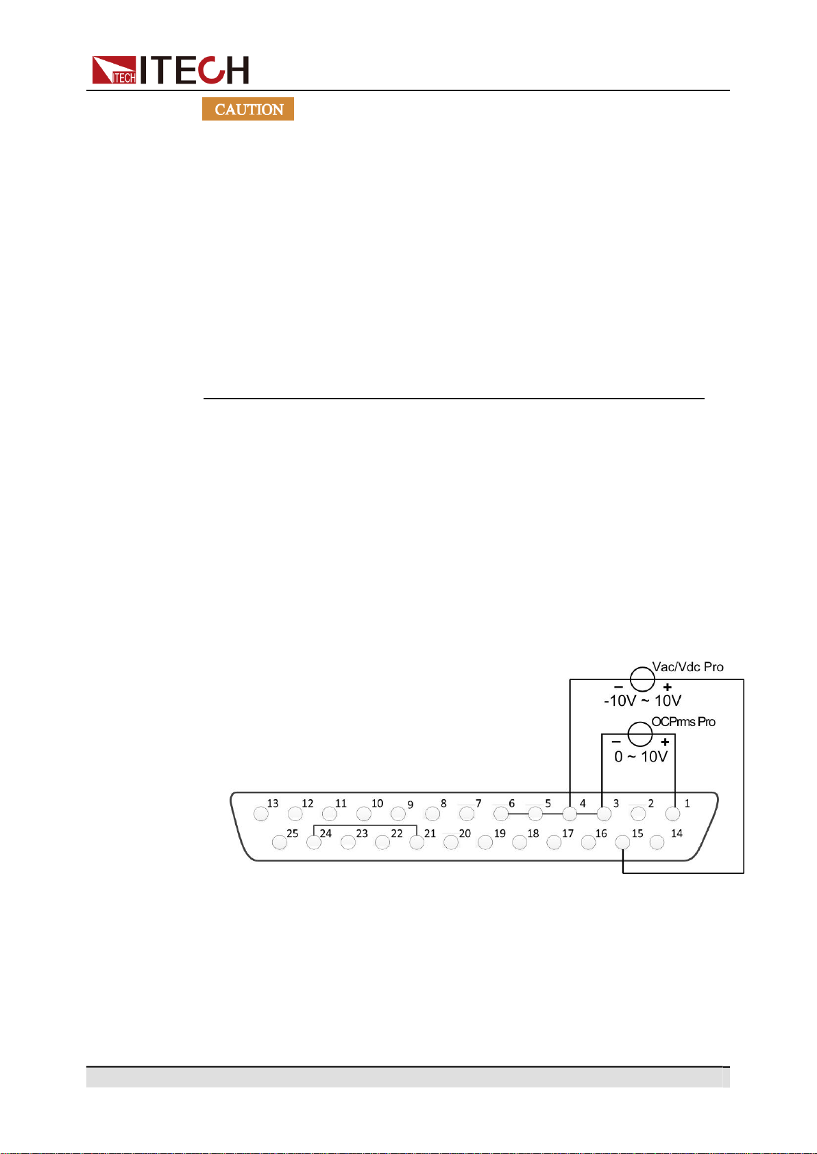
Copyright © Itech Electronic Co., Ltd.
69
Operation and Application
•
Before connecting the hardware device that controls the analog in-
terface, make sure that the hardware device does not output a volt-
age higher than 20% of the specified value to the pin, otherwise the
instrument will be damaged. For example, when setting the voltage
or current, the input voltage can’t exceed 12V, otherwise the instru-
ment will be damaged.
•
In analog remote control mode, the analog signal input pin cannot
be left floating. Before enabling the external analog function, verify
that pin 1 (OCPrms Program) and pin 15 (Vac/Vdc Program) are
connected correctly.
•
Safe electrical isolation is set between this analog interface and
output electrode. Do not connect any ground wire of the analog in-
terface to the positive and negative terminals of the output
interface.
4.10.2
Enable/Disable Analog Control
To use the external analog control function, you must enable the analog control
in the system menu. The setting steps are as follows:
1.
Correctly install the IT-E1208 optional card. For details, refer to 2.6 Connect-
ing the Interface.
2.
Correctly connect the Pin 1 (OCPrms Program) and Pin 15 (Vac/Vdc Pro-
gram): Connect an external DC voltage source capable of outputting 0V ~
10V voltage between Pin 1 and Pin 3 and between Pin 15 and Pin 4 respec-
tively, as shown below.
3.
Enable/disable analog quantity function.
a.
Press the composite keys [Shift] + [DC](System) to enter into the system
menu interface.
b.
Rotate the knob to select I/O Advance Config and press [Enter] key to
confirm.
c.
Rotate the knob to select Local/Analog and press [Enter] key to
confirm.

Copyright © Itech Electronic Co., Ltd.
70
Operation and Application
d.
Rotate the knob to switch Local and Analog options. After selecting
Local or Analog, press [Enter] key to confirm.
•
Local: Default value, indicating that the voltage and current setting
values are controlled by the front panel, and the DB25 device does
not receive input or output.
•
Analog: indicate that the [V-set] and [I-set] keys on the front panel
are invalid, and the voltage and current setting values are controlled
by the DB25 device.
e.
Press [Esc] to exit the system menu setting.
4.10.3
Analog Quantity Control
Output On/Off Control
Pin 8(On/Off input) can be used to control the power supply output, which is
controlled by the trigger signal input by this pin. The falling time or rising time of
the trigger signal controls the output. The operation steps are as follows:
1.
Enable the analog control. For details, refer to 4.10.2 Enable/Disable Analog
Control.
2.
Select the slope of the trigger signal: rising time or falling time.
a.
Press the composite keys [Shift] + [DC](System) to enter into the system
menu interface.
b.
Rotate the knob to select I/O Advance Config and press [Enter] key to
confirm.
c.
Rotate the knob to select Ext In Edge and press [Enter] key to confirm.
d.
Rotate the knob to switch Hi/Act and Lo/Act options. After selecting
Hi/Act or Lo/Act, press [Enter] key to confirm.
•
Hi/Act: default value, indicating that the rising time is triggered. If the
Pin 8 input signal is from 0V to 5V, the power output is controlled by
the [On/Off] key on the front panel.
•
Lo/Act: indicate that the falling time is triggered. If the Pin 8 input sig-
nal is from 5V to 0V, the power output is controlled by the [On/Off]
key on the front panel.
e.
Press [Esc] to exit the system menu setting.
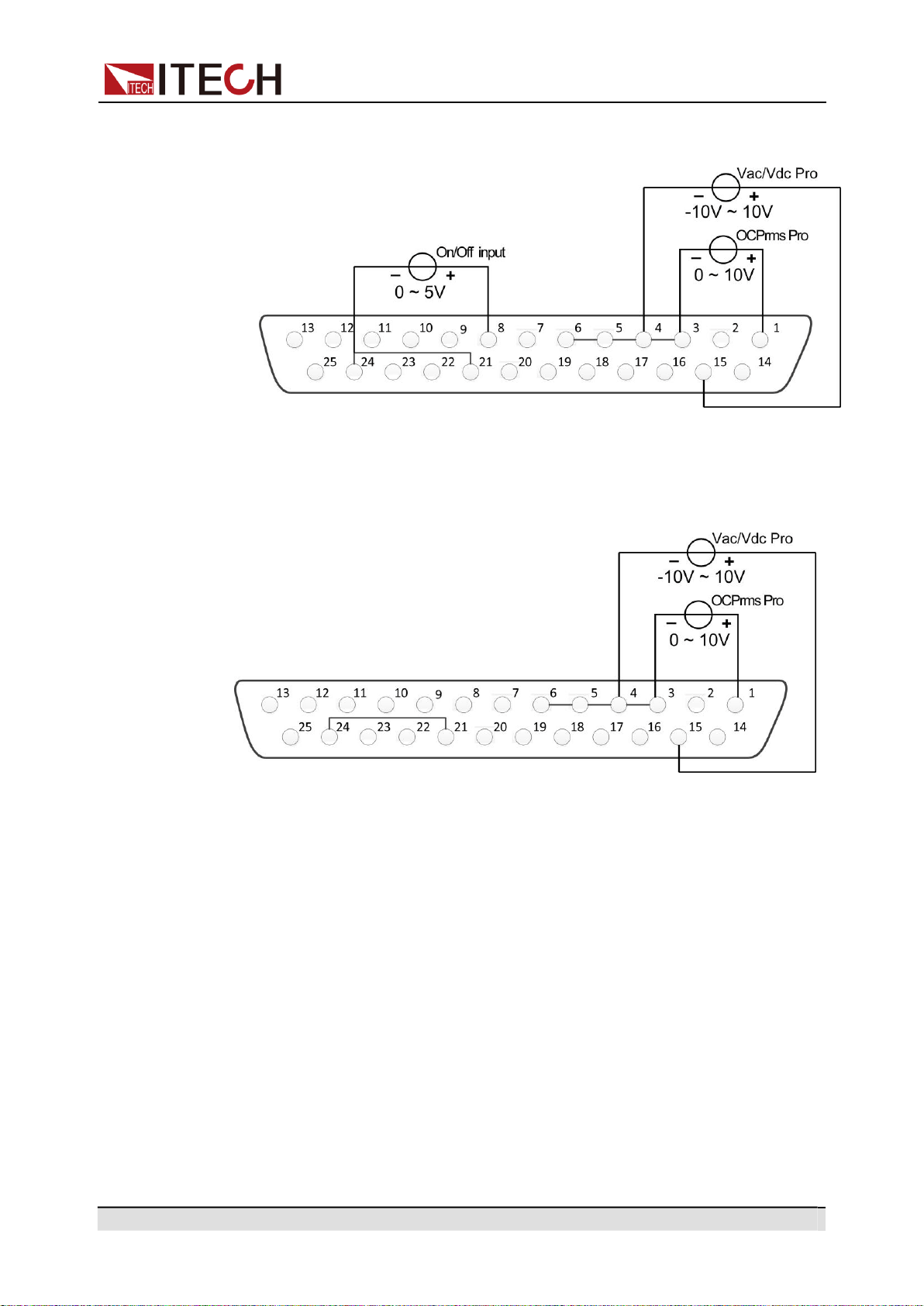
Copyright © Itech Electronic Co., Ltd.
71
Operation and Application
3.
There is an external DC voltage source capable of outputting 0V ~ 5V volt-
age between Pin 8 and Pin 24 of the DB25 interface to control power output.
Analog Programming of Voltage and Current
This function can remotely change the voltage and current settings by sending
an external analog signal. The connection diagram is as follows:
•
AC Mode
–
Voltage setting: Analog control of the output voltage can be accom-
plished by connecting external DC voltage sources in the range of 0 V to
10 V to the 15 and 4 pins.
–
Current setting: Analog control of the output current can be accomplished
by connecting external DC voltage sources in the range of 0 V to 10 V to
the 1 and 3 pins.
By connecting a voltage source to the Vac Pro or OCPrms Pro pins, a volt-
age setting from 0 to + 10 V corresponds to the zero to full-scale voltage or
current setting of the power supply.
For example, if the maximum rated value is 300 V, and if the voltage source
is set to 5 V, the setting voltage should be approximately 150 V. If the maxi-
mum rated value is 6 A, and if the voltage source is set to 5 V, the setting
current should be approximately 3 A.
•
DC Mode
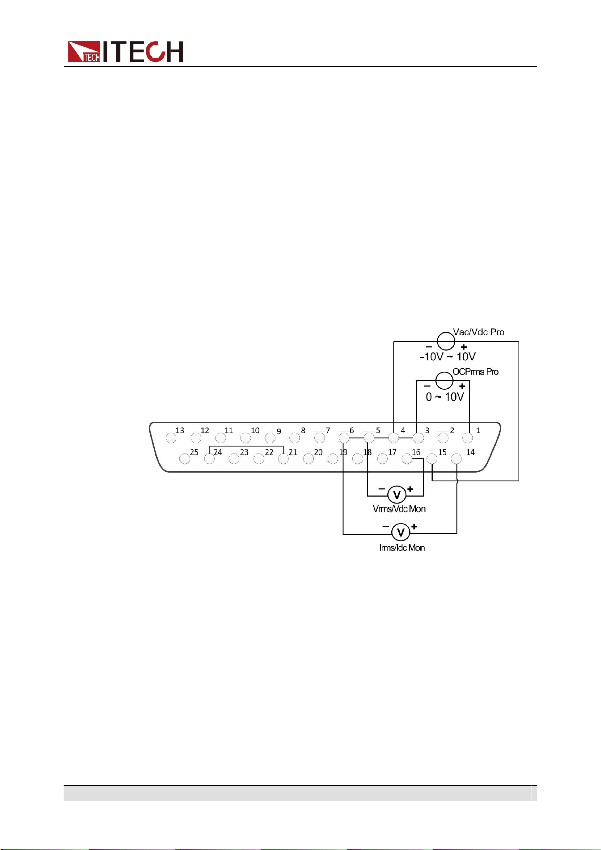
Copyright © Itech Electronic Co., Ltd.
72
Operation and Application
–
Voltage setting: Analog control of the output voltage can be accom-
plished by connecting external DC voltage sources in the range of -10 V
to 10 V to the 15 and 4 pins.
–
Current setting: Analog control of the output current can be accomplished
by connecting external DC voltage sources in the range of 0 V to 10 V to
the 1 and 3 pins.
By connecting a voltage source to the Vac Pro or OCPrms Pro pins, a volt-
age setting from - 10 V to + 10 V or 0 to + 10 V corresponds to the zero to
full-scale voltage or current setting of the power supply.
For example, if the rated value ranges from - 400 V to + 400 V , and if the
voltage source is set to -5 V, the setting voltage should be approximately
-200 V. If the maximum rated value is 6 A, and if the voltage source is set to
5 V, the setting current should be approximately 3 A.
Analog Monitoring of Voltage and Current
This function can monitor and read the output voltage and current values. The
connection diagram is as follows:
•
Current monitoring: Output voltage values can be monitored and read by
connecting a digital voltmeter to the 14 and 6 pins.
•
Voltage monitoring: Output current values can be monitored and read by
connecting a digital voltmeter to the 16 and 5 pins.
By connecting a digital voltmeter to the Vrms/Vdc Monitor or Irms/Idc Monitor
pins, a voltage reading from 0 to + 10 V corresponds to the zero to full-scale
voltage or current output of the power supply.
For example, if the maximum rated value is 300 V, and if the pin 16 generates
2.5 V, the output voltage should be approximately 75 V. If the maximum rated
value is 6 A, and if the pin 14 generates 1 V, the output current should be ap-
proximately 0.6 A.
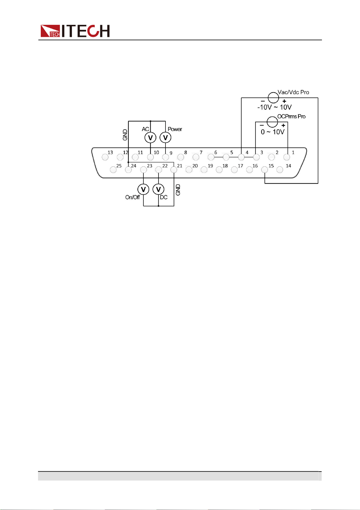
Copyright © Itech Electronic Co., Ltd.
73
Operation and Application
Monitoring of output status
You can connect a standard multi-meter to a pin with appropriate status to moni-
tor the output mode, loaded status and On/Off status of the instrument. The con-
nection diagram is as follows:
•
Monitor the AC output mode: When Pin 10 outputs 5V, it indicates that the
instrument is in the AC mode; otherwise, Pin 10 will output 0V.
•
Monitor the DC output mode: When Pin 22 outputs 5V, it indicates that the
instrument is in the DC mode; otherwise, Pin 22 will output 0V.
•
Monitor the instrument load status: If the instrument is under normal loading
status, Pin 9 will output 5V; if the instrument is in unloaded status, Pin 9 will
output 0V.
•
Monitor the instrument On/Off status: When the instrument is On, Pin 23 will
output 5V; when the instrument is Off, Pin 23 will output 0V.
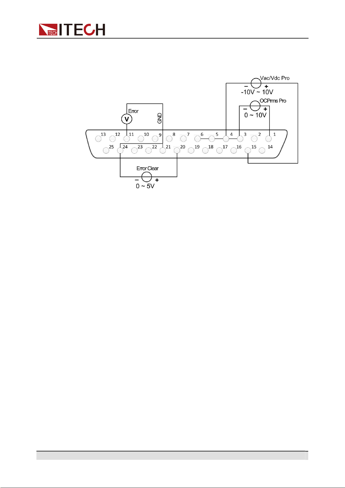
Copyright © Itech Electronic Co., Ltd.
74
Operation and Application
Monitor and Clear Error Status
This function can monitor and clear the instrument error status. The connection
diagram is as follows:
•
Monitor instrument error status: if the instrument occurs error status (Over
OVPrms or OVPpeakor UVPrms or OCPrmsor OCPpeak or Over tempera-
ture or Fan Error), Pin 11 will output 5V; if the instrument is in a non-error
status, Pin 11 will output 0V.
•
Clear instrument error status: when Ext In Edge = Hi/Act, if Pin 20 input is
from 0V to 5V, the error status indicated by Pin 11 will be cleared; when Ext
In Edge = Lo/Act, if Pin 20 input is from 5V to 0V, the error status indicated
by Pin 11 will be cleared.

Copyright © Itech Electronic Co., Ltd.
75
Multi-units operation
5 Multi-units operation
Series Operation
Three-phase Operation
In multi-units operation, the output waveform only supports Sine waveform.
5.1
Series Operation
IT-M7721/IT-M7722 power supply support series operation, series connection
can be applied between same models to increase output power and output volt-
age, but it can’t be applied between different models. IT-M7721/IT-M7722
power supply supports up to two power supplies in series.
For example, the output specification of IT-M7721 is 300V/1A/300VA, then the
total output after series is 600V/1A/600VA, the output power and output voltage
are both double. This chapter takes two IT-M7721 power supply as an example
to describe how to series the single units and how to return from series mode to
single mode.
Operation steps
1.
Connect the instruments according to the following diagram.
•
Local sense
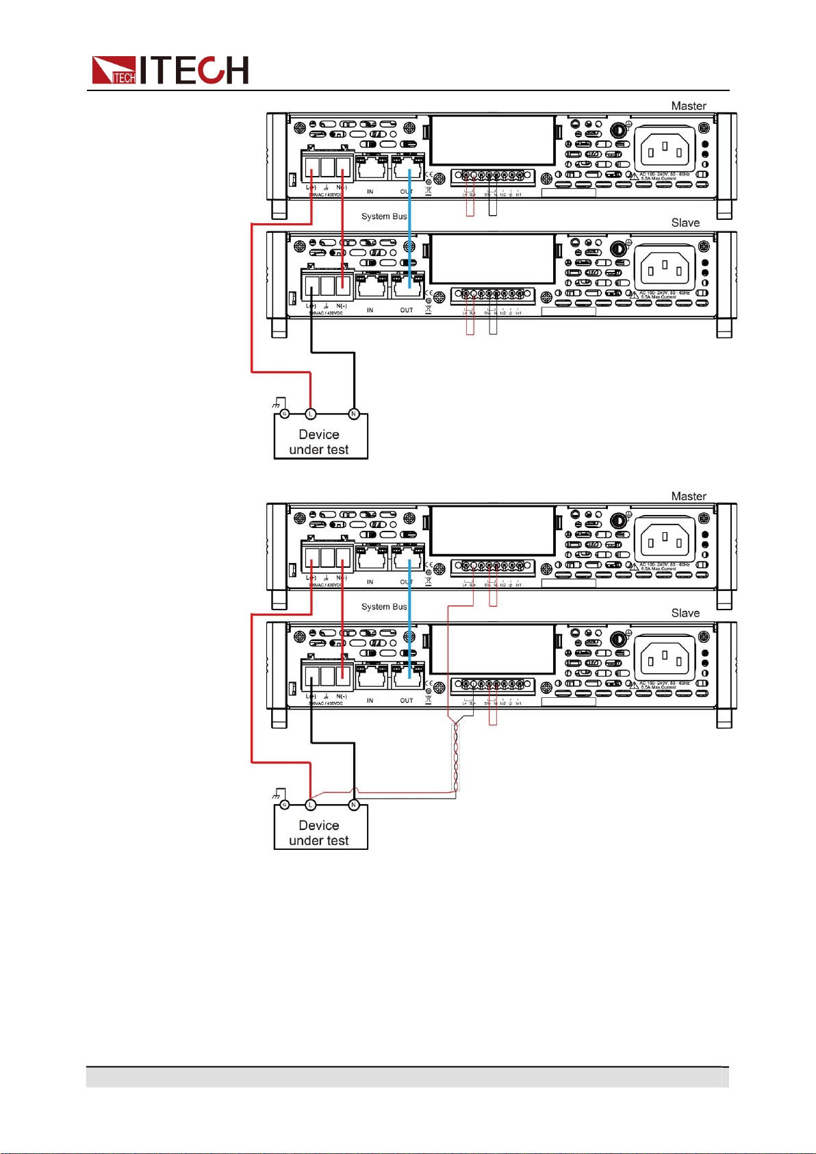
Copyright © Itech Electronic Co., Ltd.
76
Multi-units operation
•
Remote sense
a.
Use standard network cables to connect System Bus terminals.
b.
Connect the AC output terminals of the two units in series and connect
them to the DUT.
c.
Connect the power cords of 2 stand-alone units, please refer to 2.4 Con-
necting the Power Cord for details.
2.
Set two units as master 1 and slave 2 respectively.
a.
Press the composite keys [Shift]+[V-set](Config) to enter into the config-
uration menu interface.
b.
Rotate the knob to select Parallel and press [Enter] key to confirm.
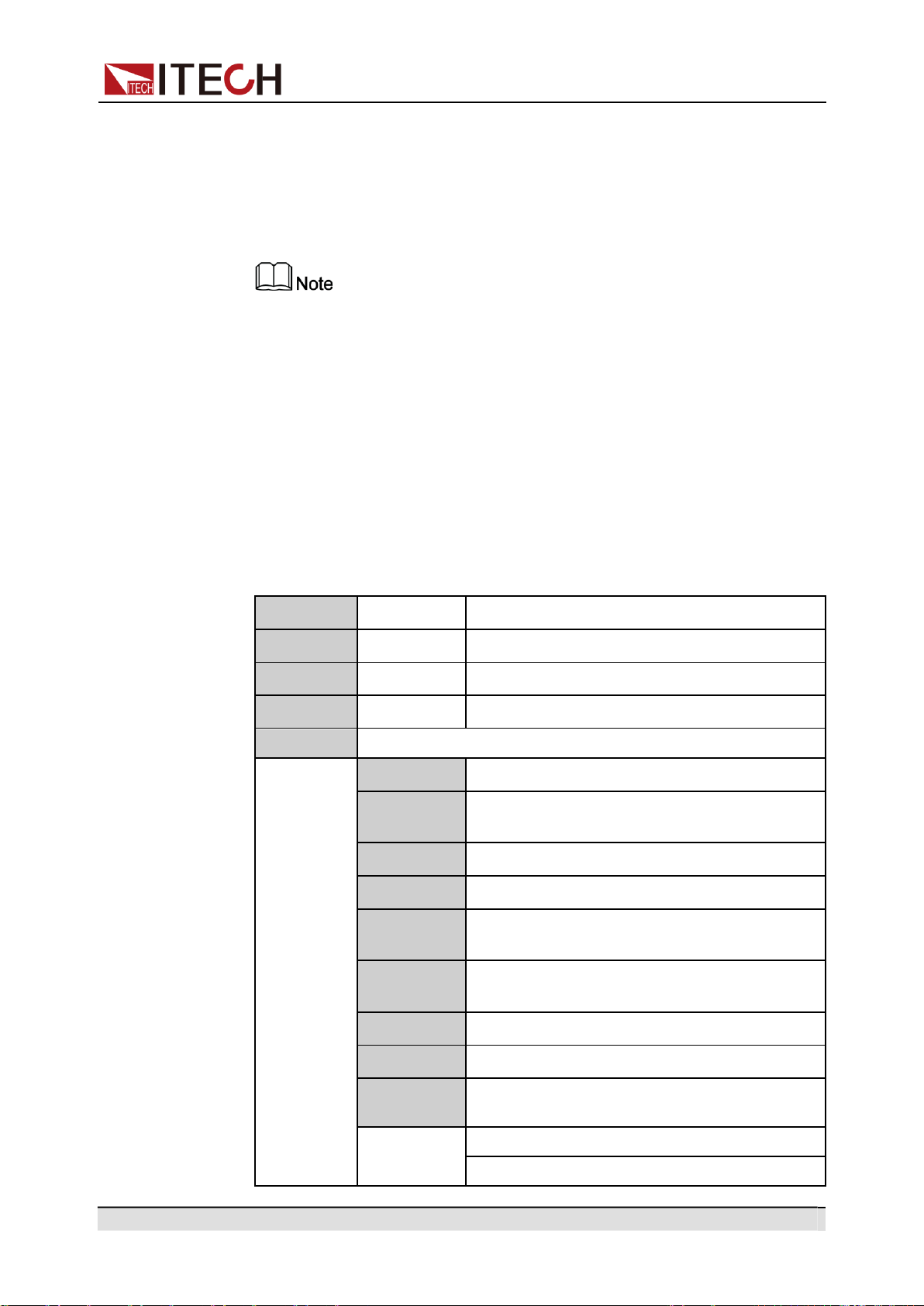
Copyright © Itech Electronic Co., Ltd.
77
Multi-units operation
c.
Rotate the knob to select “600V/1A” and press [Enter] key to confirm.
d.
Set the 600V/1A Role menu items of the two units to 1 and 2, respec-
tively, and press [Enter] to confirm.
•
600V/1A Role = 1, it means this unit is the master 1.
•
600V/1A Role = 2, it means this unit is the slave 2.
In series mode, the phase difference between the two power supplies is
fixed at 180 degree and cannot be changed.
3.
Connect two tandem units online.
Press the [Link] button on the front panel of the master A to connect the two
synchronous data. After the synchronization is complete, the [Link] indica-
tors of the master A and slave B will light up one after another. Press the
[Link] key on the front panel of the master A again to cancel the synchroni-
zation, and the [Link] lights of both power supplies will lights off.
4.
Set the series output.
Please refer to 3.3 Applying Waveform Output to set the series output. When
setting, just set the data of master A, slave B will automatically synchronize
the data of A. The details of the data that can be synchronized are shown in
the following table:
Vac
[V-set]
Sets the output voltage value.
OCPrms
[I-set]
Sets the OCPrms value.
Freq
[F-set]
Sets the frequency value.
On or Off
[On/Off]
Turns the instrument output on or off.
Protect
Protection function
1:OVP(rms)
Over-voltage protection(rms)
2:OVP
(peak)
Over-voltage protection(peak)
3:UVP(rms)
Under-voltage protection(rms)
4:OCP(rms)
Over-current protection(rms)
5:OCP
(peak)
Over-current protection(peak)
6:OCP
Delay
OCP delay
7:OPP
Over-power protection
8:MCL
Current limiting protection
10:Range
Set
Setting value range
1:Vac-Max
2:Vac-Min
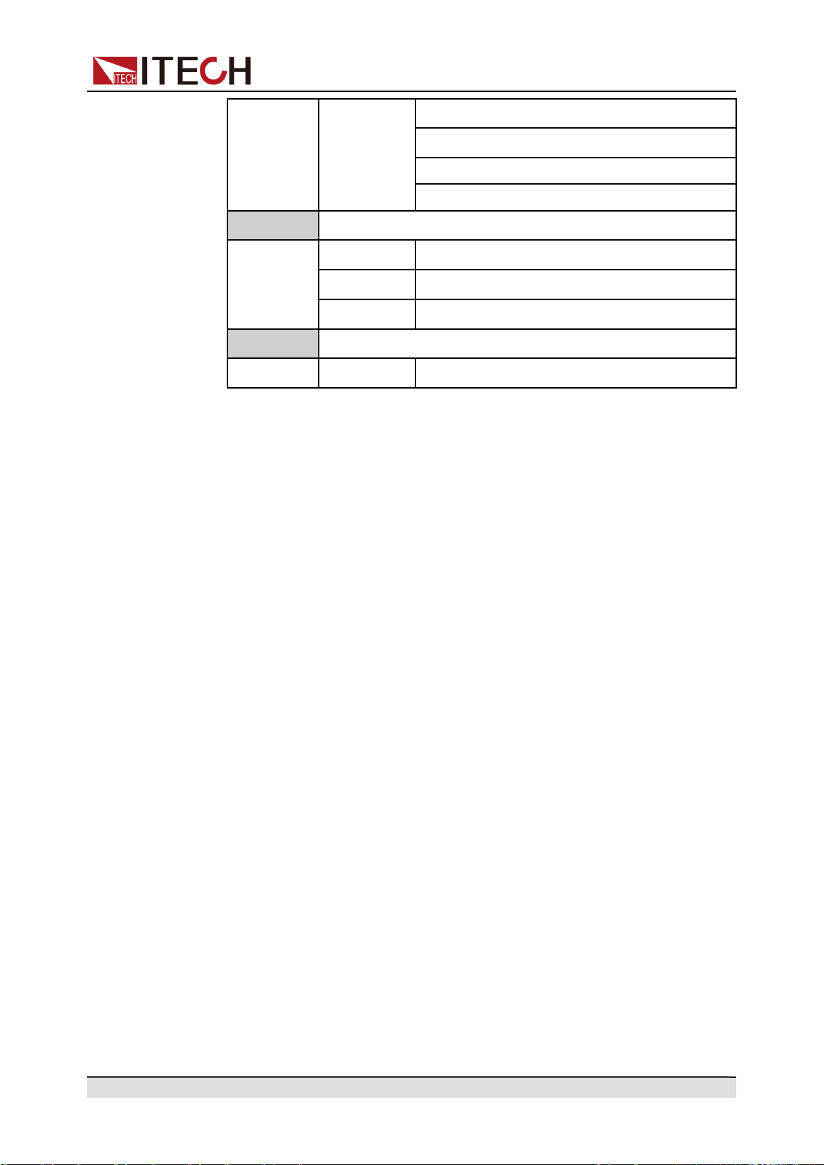
Copyright © Itech Electronic Co., Ltd.
78
Multi-units operation
5:Freq-Max
6:Freq-Min
7:OCP-Max
8:OCP-Min
Config
Config function
1:I Range
Set the current measurement range.
3:On Phase
Set the starting phase angle of the waveform.
4:Off Phase
Set the ending phase angle of the waveform.
System
System function
5:Relay Ctrl
Set the relay control.
Revert to single mode
1.
Press the [Link] key on the front panel of master A to cancel the serial
synchronization.
2.
Set each of the two instruments to single mode.
a.
Press the composite keys [Shift]+[V-set](Config) to enter into the config-
uration menu interface.
b.
Rotate the knob to select Parallel and press [Enter] key to confirm.
c.
Rotate the knob to select Single and press [Enter] key to confirm.
3.
Power off the two instruments and disconnect the power cord.
4.
Remove the cables connection of the System Bus and AC output terminals
between two units.
5.
Power on the two instruments separately. After the instrument is restarted,
the VFD shows that the instrument is working in single mode.
5.2
Three-phase Operation
Three AC sources can be combined to provide three-phase AC power when re-
quired. IT-M7721/IT-M7722 supports 3-phase output via three units. The three
units need to be connected together via System Bus to achieve 3-phase output
function of AC power supply. This chapter takes three IT-M7721 power supply
as an example to describe how to realize 3-phase in a single units and how to
return from 3-phase mode to single mode.
Operation steps
1.
Connect the instruments according to the following diagram.
•
Local sense
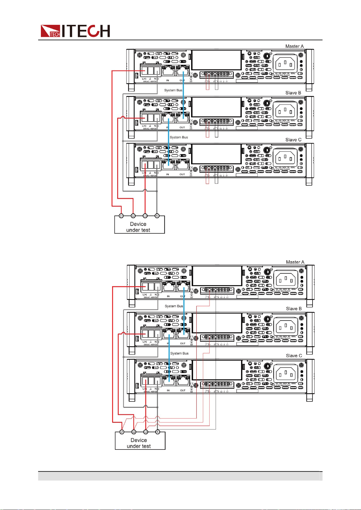

Copyright © Itech Electronic Co., Ltd.
80
Multi-units operation
a.
Use standard network cables to connect System Bus terminals.
b.
Connect the AC output terminals of the three units in three-phase and
connect them to the DUT.
c.
Connect the power cords of 3 stand-alone units, please refer to 2.4 Con-
necting the Power Cord for details.
2.
Set 3 single units as phase A, phase B and phase C respectively.
a.
Press the composite keys [Shift]+[V-set](Config) to enter into the config-
uration menu interface.
b.
Rotate the knob to select Parallel and press [Enter] key to confirm.
c.
Rotate the knob to select 3 Phase and press [Enter] key to confirm.
d.
Set the 3 Phase Role menu items of 3 units to A, B and C, and press
[Enter] to confirm.
•
3 Phase Role = A, it means this unit is the master A.
•
3 Phase Role = B, it means this unit is the slave B.
•
3 Phase Role = C, it means this unit is the slave C.
e.
Set the Degree menu items of 3 units to 0.0 degree, 120.0 degree and
240.0 degree, and press [Enter] to confirm.
•
Degree = 0.0° (Fixed value), it means this unit is the master A.
•
Degree = 120.0°, it means the slave B is 120 degree ahead of the
master A.
•
Degree = 240.0°, it means the slave C is 240 degree ahead of the
master A.
In 3-phase mode, the default phase difference between each two power
supplies is 120.0 degree, and the phase difference between each two
power supplies cannot be less than 5 degree.
3.
Connect three three-phase units.
Press the [Link] button on the front panel of the master A to connect the
three synchronous data. After the synchronization is complete, the [Link] in-
dicators of the master A, slave B and slave C will light up one after another.
Press the [Link] key on the front panel of the master A again to cancel the
synchronization, and the [Link] lights of three power supplies will lights off.
4.
Set the three-phase output.
Please refer to 3.3 Applying Waveform Output to set the three-phase output.
When setting, just set the data of master A, slave B and slave C will auto-
matically synchronize the data of A. The details of the data that can be
synchronized are shown in the following table:
Vac
[V-set]
Sets the output voltage value.
OCPrms
[I-set]
Sets the OCPrms value.
Freq
[F-set]
Sets the frequency value.
On or Off
[On/Off]
Turns the instrument output on or off.
Protect
Protection function
Copyright © Itech Electronic Co., Ltd.
81
Multi-units operation
1:OVP(rms)
Over-voltage protection(rms)
2:OVP
(peak)
Over-voltage protection(peak)
3:UVP(rms)
Under-voltage protection(rms)
4:OCP(rms)
Over-current protection(rms)
5:OCP
(peak)
Over-current protection(peak)
6:OCP
Delay
OCP delay
7:OPP
Over-power protection
8:MCL
Current limiting protection
10:Range
Set
Setting value range
1:Vac-Max
2:Vac-Min
5:Freq-Max
6:Freq-Min
7:OCP-Max
8:OCP-Min
Config
Config function
1:I Range
Set the current measurement range.
3:On Phase
Set the starting phase angle of the waveform.
4:Off Phase
Set the ending phase angle of the waveform.
System
System function
5:Relay Ctrl
Set the relay control.
5.
To test the DUT under Unbalance three-phase mode, you can connect the
communication interface (GPIB/USB/RS232/LAN/CAN) of the host A to the
PC. Please refer to 2.6 Connecting the Interface.
Set the three-phase voltage value and the angle difference of the three
phases through PC. For specific setting instructions, please refer to "IT-
M7700 Programming and Grammar Guide".
Revert to single mode
1.
Press the [Link] key on the front panel of master A to cancel the three-phase
synchronization mode.
2.
Set each of the three instruments to single mode.

Copyright © Itech Electronic Co., Ltd.
82
Multi-units operation
a.
Press the composite keys [Shift]+[V-set](Config) to enter into the config-
uration menu interface.
b.
Rotate the knob to select Parallel and press [Enter] key to confirm.
c.
Rotate the knob to select Single and press [Enter] key to confirm.
3.
Power off the three units and disconnect the power cord.
4.
Remove the cables connection of the System Bus and AC output terminals
between three units.
5.
Power on the three units separately. After the instrument is restarted, the
VFD shows that the instrument is working in single mode.

Copyright © Itech Electronic Co., Ltd.
83
Routine Maintenance
6 Routine Maintenance
This chapter describes general maintenance items and maintenance methods
of the IT-M7700 series power source.
Instrument Self-Test
Cleaning and Maintenance
Prompt Information Reference
Contact of ITECH Engineers
Return for Repair
6.1
Instrument Self-Test
Self-test checks that the minimum set of logic and power mesh systems are
functioning properly. Self-test does not enable the output or place any voltages
on the output. Self-test can be achieved in two ways:
•
Re-start the instrument. Each time the instrument is powered on, the selftest
is performed. This test assumes that the instrument is running.
•
SCPI command: *TST?. If the return value is 0, the self-test passes; if it is 1,
the self-test fails. If the self-test fails, please send command SYSTem:ER-
Ror? to view the self-test error. Please refer to IT-M7700 Programming
Guide for the list of error codes.
6.2
Cleaning and Maintenance
To ensure the safety function and performance of the instrument, please clean
and maintain the instrument properly.
•
To prevent electrical shock, disconnect the instrument from AC
mains power and disconnect all test leads before cleaning.
•
Do not use detergent or solvents.
•
Do not disassemble the instrument and attempt to clean internally.
Clean the outside and the front panel screen of the instrument using a soft, lint
free, cloth slightly dampened with water. Use a brush to clean the dust on the
vent and cooling fans.
Copyright © Itech Electronic Co., Ltd.
84
Routine Maintenance
6.3
Prompt Information Reference
The IT-M7700 series power supply has a detailed error and prompt information
function, so as to help the user to easily carry out positioning and measurement
during measurement and use.
This section describes all error information of the IT-M7700 series power supply
as well as disposals. All prompt information is listed.
Error information list
Error information
Description and disposals
OVPrms Occurred!!
The voltage value read on the panel exceeds the OVPrms setting
value. Check whether the OVPrms setting value is too low or the
output voltage setting value is too high.
OVPpeak Occurred!!
The peak value of the output voltage readback exceeds the OVP-
peak setting value. Check whether the OVPpeak setting value is
too low or the output voltage peak value is too high.
UVPrms Occurred!!
The readback value when the output voltage is stable is lower
than the UVPrms setting value. Check whether the UVPrms set-
ting value is too high or whether there is sudden voltage drop due
to abnormal loading.
OCPrms Occurred!!
The current value read on the panel exceeds the OCPrms setting
value. Check whether the OCPrms setting value is too low or
whether the load is too large.
OCPpeak Occurred!!
The peak value of the output current readback exceeds the OCP-
peak setting value. Check whether the OCPpeak setting value is
too low or the output current peak value is too high.
OPP Occurred!!
The total output power exceeds the OPP setting value. Check
whether the OPP setting value is too low or whether the load is
too large.
Over Temp Occurred!!
The system temperature is too high. Check whether the fan is
stopped or whether the rotation speed is not increased along with
the output load.
Fan Error Occurred!!
The fan rotation speed cannot be detected. Check whether the
fan is stopped due to abnormality.
DD_OCP Occurred!!
The over-current protection of the hardware (DCtoDC power lev-
el) is triggered. Check whether the output has short circuit or ab-
normal loading.
DA_OCOVP Occurred!!
The hardware protection of the hardware (DCtoAC power level) is
triggered. Check whether the output has short circuit or abnormal
loading.
PFC fail Occurred!!
The communication cannot be established between the DSP con-
trol board and PFC power level.
Copyright © Itech Electronic Co., Ltd.
85
Routine Maintenance
Error information
Description and disposals
OPP Limit Occurred!!
The instantaneous output power exceeds the maximum load that
the hardware can bear. Check whether the output has short cir-
cuit or abnormal loading.
DSP disconnected!!
The communication of the control board is abnormal. Check the
communication cable between the UI display board and the con-
trol board (DSP).
Interface disconnected!!
The adapter card communication is abnormal or the communica-
tion card is not installed.
SCPI Error xxx
There is a SCPI command error. Refer to “SYS- Tem:ERRor?” in
the IT-M7700 Programming and Syntax Guide for codes.
System Restart
PFC power level startup abnormal.
Prompt message list
Prompt message
Description
TEST MEMORY
The memory is initialized.
List Test x
The List x data is initialized.
Read LIST x Data
Read the xth LIST data.
AC Power Off
Switch off the power.
Invailid in Output Mode
This operation is unavailable under the Output mode.
Invailid in DC Mode
This operation is unavailable under the DC mode.
Over 100 Hz
The frequency setting is over 100 Hz and the MCL cannot be ad-
justed at this time.
Invalid in AC+DC = Off
When the AC+DC function is off, the AC or DC cannot be
switched when the power output is On.
Invalid in Analog Ctrl
V-Set and I-Set are controlled by analog and cannot be controlled
from the front panel of the power supply.
6.4
Contact of ITECH Engineers
This section describes operations to be carried out by the user in case of failure
of the instrument.
Preparation before contact
When the instrument fails, you should make the following preparations before
returning the instrument to ITECH for repair or contacting engineers.

Copyright © Itech Electronic Co., Ltd.
86
Routine Maintenance
•
Check all the items listed in the Self-inspection of equipment faults and con-
firm whether there are still some problems.
•
Collect the SN number
If there are still some problems, carefully read the Warranty and Limitation of
Warranty in the preface of the manual. Confirm that your instrument complies
with warranty service conditions. If after your warranty expires, ITECH offers re-
pair services at competitive prices.
Self-inspection of equipment faults
When the instrument fails, make the following checks to ensure that the failure
is in the instrument rather than any external connections. If the instrument fail-
ure can be eliminated via simple inspection, the maintenance cost and time can
be saved.
•
Check whether the AC power cord is securely connected to the instrument
and to a powered outlet.
•
Check whether the front-panel Power On switch has been pushed.
•
Check whether self-inspection of the instrument is successful and whether
the specifications and performance are within the indicator ranges.
•
Check whether the instrument displays error information.
•
Use other instruments instead of this instrument for confirmation.
Collect the SN number
ITECH will constantly improve the product performance, availability and reliabil-
ity. The service personnel of ITECH will record changes of each instrument. All
relevant information is marked uniquely according to the serial number of each
instrument. The equipment returned for repair must adopt the SN number as the
tracking ID.
When you contact the engineer, the effective SN number of the instrument will
be the effective guarantee for effective service and complete information. You
can obtain the SN number of the instrument by the following ways:
1.
Press the composite keys [Shift]+[DC](System) to enter into the system
menu interface.
2.
Rotate the knob to select System Info and press [Enter] key to confirm.
3.
Rotate the knob to view the SN number.
Please record the SN number and provide SN information when doing main-
tenance service.

Copyright © Itech Electronic Co., Ltd.
87
Routine Maintenance
How to contact ITECH engineers
Access ITECH official website www.itechate.com or call the service number
4006-025-000 for technical support and services.
6.5
Return for Repair
If your instrument fails during the warranty period, ITECH will repair or replace it
under the terms of your warranty. After your warranty expires, ITECH offers re-
pair services at competitive prices. Also you can purchase an extended mainte-
nance service contract that exceeds the standard warranty period.
Get Repair Service
To get the service for your instrument, choose the easiest way to contact the
ITECH engineers. ITECH will arrange for repair or replacement of your instru-
ment or provide warranty and repair cost information (if applicable).
Repackaging for Shipment
Never use styrene pellets in any shape as packaging materials.
They do not adequately cushion the instrument or prevent it from
shifting in the carton. Styrene pellets cause the instrument dam-
age by generating static electricity and by lodging in the rear
panel.
ITECH recommends that you retain the original shipping carton for return ship-
ments and always insure shipments. To ship the unit to ITECH for service or
repair:
1.
Download the ITECH maintenance service application from our website,
complete it and place it in the box with the instrument.
2.
Place the unit in its original container with appropriate packaging material.
If the original shipping container is unavailable, use a container that will en-
sure at least 10 cm (4 in.) of compressible packaging material around the en-
tire instrument. Use static-free packaging materials.
3.
Secure the container with strong tape or metal bands.
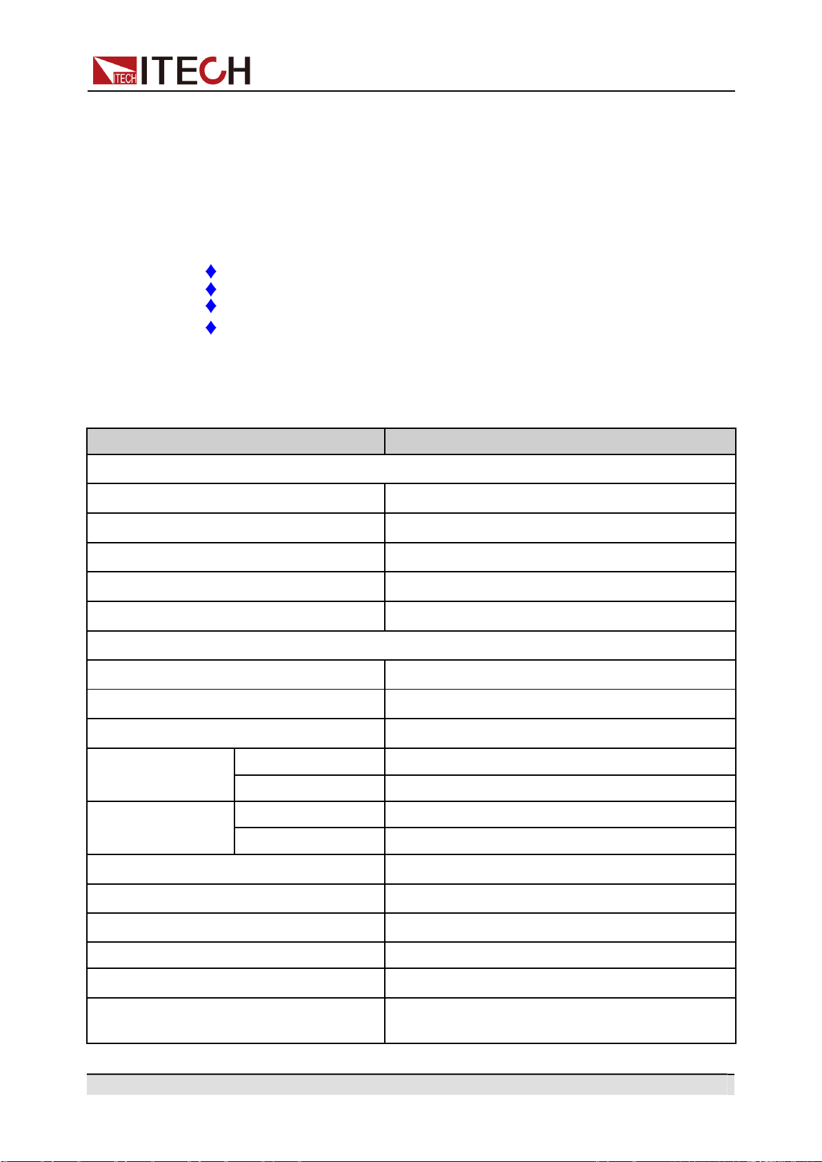
Copyright © Itech Electronic Co., Ltd.
88
Technical Specification
7 Technical Specification
This chapter will introduce the rated voltage, current, power and many other
main parameters of IT-M7700 series power source.
IT-M7721
IT-M7721L
IT-M7722
IT-M7722L
7.1 IT-M7721
Parameter
IT-M7721
AC Input
Input voltage
100–240Vac (±10%)
Phase
Single-phase
Frequency
47–63Hz
Max. input current
2A/4.3A
Power factor
0.99 (Typical)
AC Output
Max. output power
300VA
Max. output voltage
300V
Output phase
Single-phase
Current range(rms)
100V
3A
300V
1A
Current range
(peak)
100V
9A
300V
3A
Output frequency range
45–1000Hz
Phase angle degree range
0–359.9°
THD*2*4
≤0.3% at 45-100Hz; ≤1% at 101-1000Hz
Crest factor
3
Line Regulation *4
≤0.06% (100V±10%) ; ≤0.03% (240V±10%)
Load Regulation
≤0.13% (100V); ≤0.04% (200V); ≤0.015%
(300V)
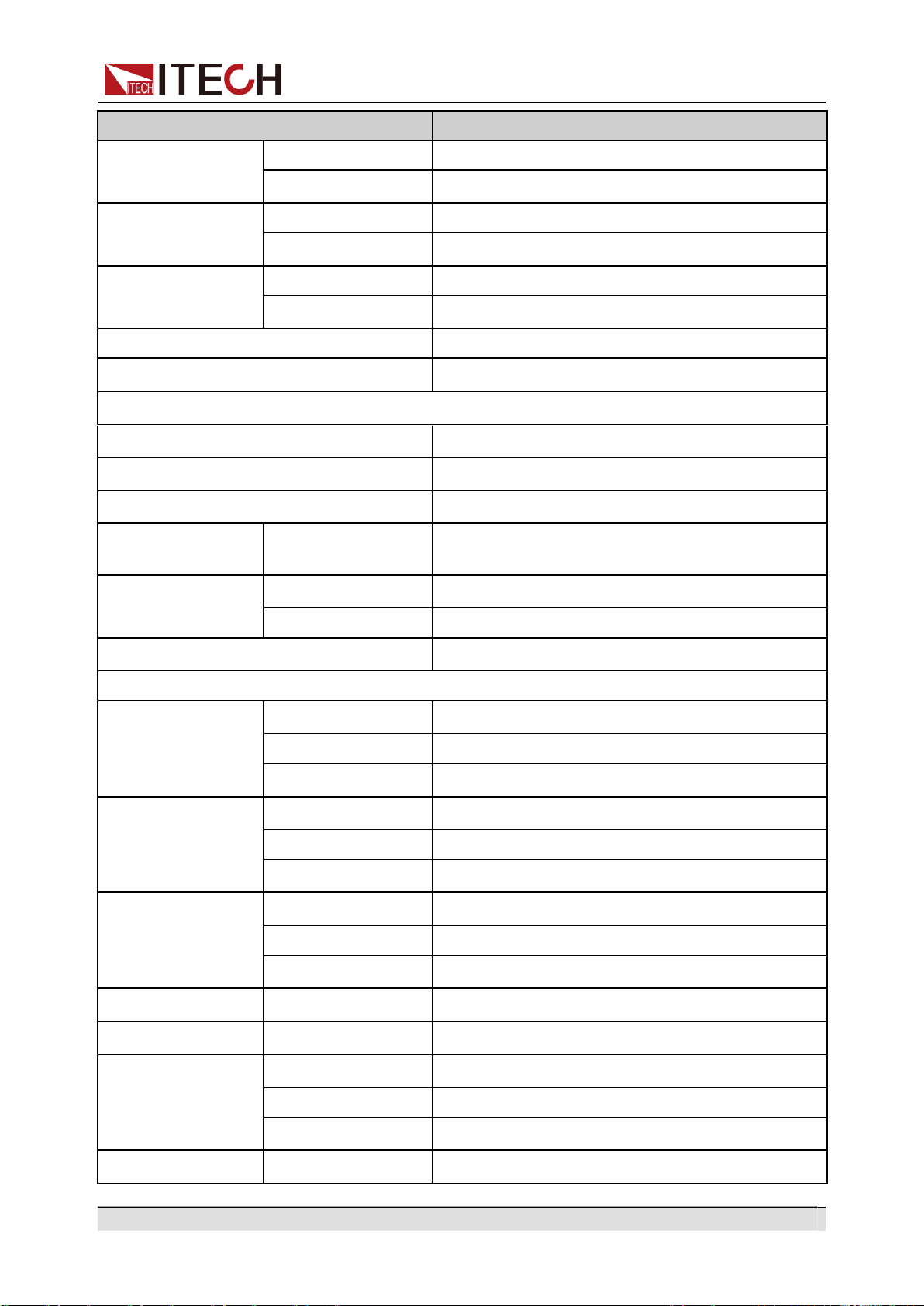
Copyright © Itech Electronic Co., Ltd.
89
Technical Specification
Parameter
IT-M7721
Output voltage
(VAC)
Resolution
0.1V
Accuracy
±(0.2%×VAC + 0.2%×F.S.)*1
Output frequency
Resolution
0.1Hz
Accuracy
±0.1%
Phase angle de-
gree range
Resolution
0.1°
Accuracy
0.5°
DC offset value
20mV
Efficiency
75% (Typical)
DC Output
Max. output power
300W
Max. output voltage
±400V
Maximum output current (rms)
±3A/±0.75A(±100V/±400V)
Output voltage
(VDC)
Accuracy
±(0.2%×VDC + 0.2%×F.S.) *1
Voltage ripple
Peak- peak
3.2V
RMS
1.27V
Dynamic response time *5
≤0.5ms
Meter
AC Voltage
Range
0-300V
Resolution
0.1V
Accuracy
±(0.25%×VAC + 0.25%×F.S.)*1
AC current (rms)
Range
0.1-3A
Resolution
10mA
Accuracy
±(0.25%×VAC + 0.25%×F.S.)*1
AC current (peak)
Range
0-4.2A
Resolution
10mA
Accuracy
±(0.4%×IP + 0.8%×F.S.)*1
DC voltage
Accuracy
±(0.25%×VDC + 0.25%×F.S.)*1
DC current
Accuracy
±(0.25%×IDC + 0.25%×F.S.)*1
Frequency
Range
45 - 1000Hz
Resolution
0.1Hz
Accuracy
±0.1%*3
Power (S)
Resolution
10mVA
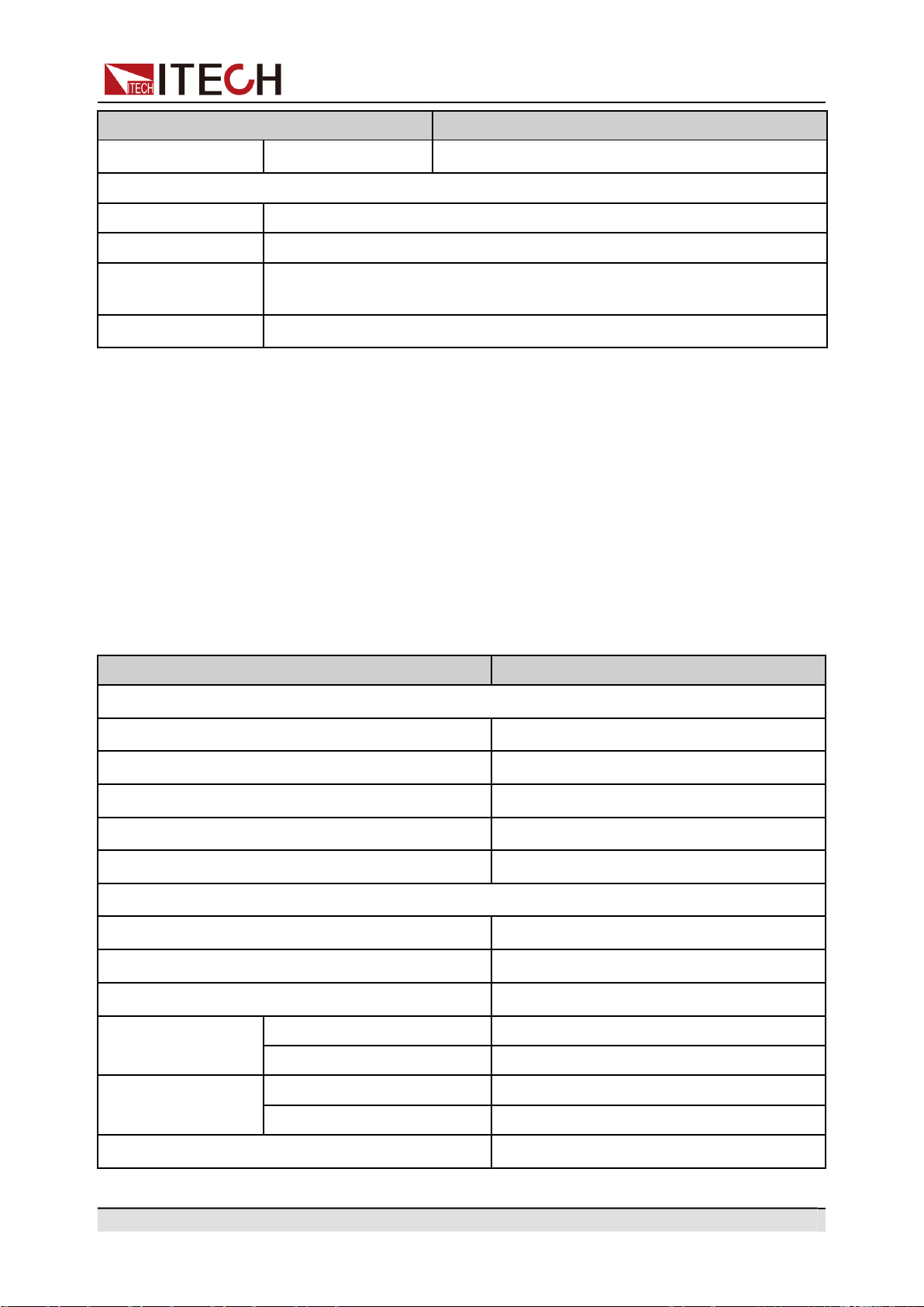
Copyright © Itech Electronic Co., Ltd.
90
Technical Specification
Parameter
IT-M7721
Accuracy
±(0.5%×S + 0.5%×F.S.)*1
Other
Protection
OVP、OCP、OTP、OPP
Interface
GPIB、USBTMC、LAN、RS232
Dimension
(WxHxD)
215 x 44.45(1U) x 450 mm
Weight
4.5Kg
*1: F.S. value is full range.
*2: Min voltage for THD test is 100Vac .
*3: Min voltage for frequency display accuracy is 100Vac.
*4: Tested with pure resistive load.
*5: From 10% to 90% full load.
7.2 IT-M7721L
Parameter
IT-M7721L
AC Input
Input voltage
100–240Vac (±10%)
Phase
Single-phase
Frequency
47–63Hz
Max. input current
2A/4.3A
Power factor
0.99 (Typical)
AC Output
Max. output power
300VA
Max. output voltage
300V
Output phase
Single-phase
Current range(rms)
100V
3A
300V
1A
Current range
(peak)
100V
9A
300V
3A
Output frequency range
45–100Hz
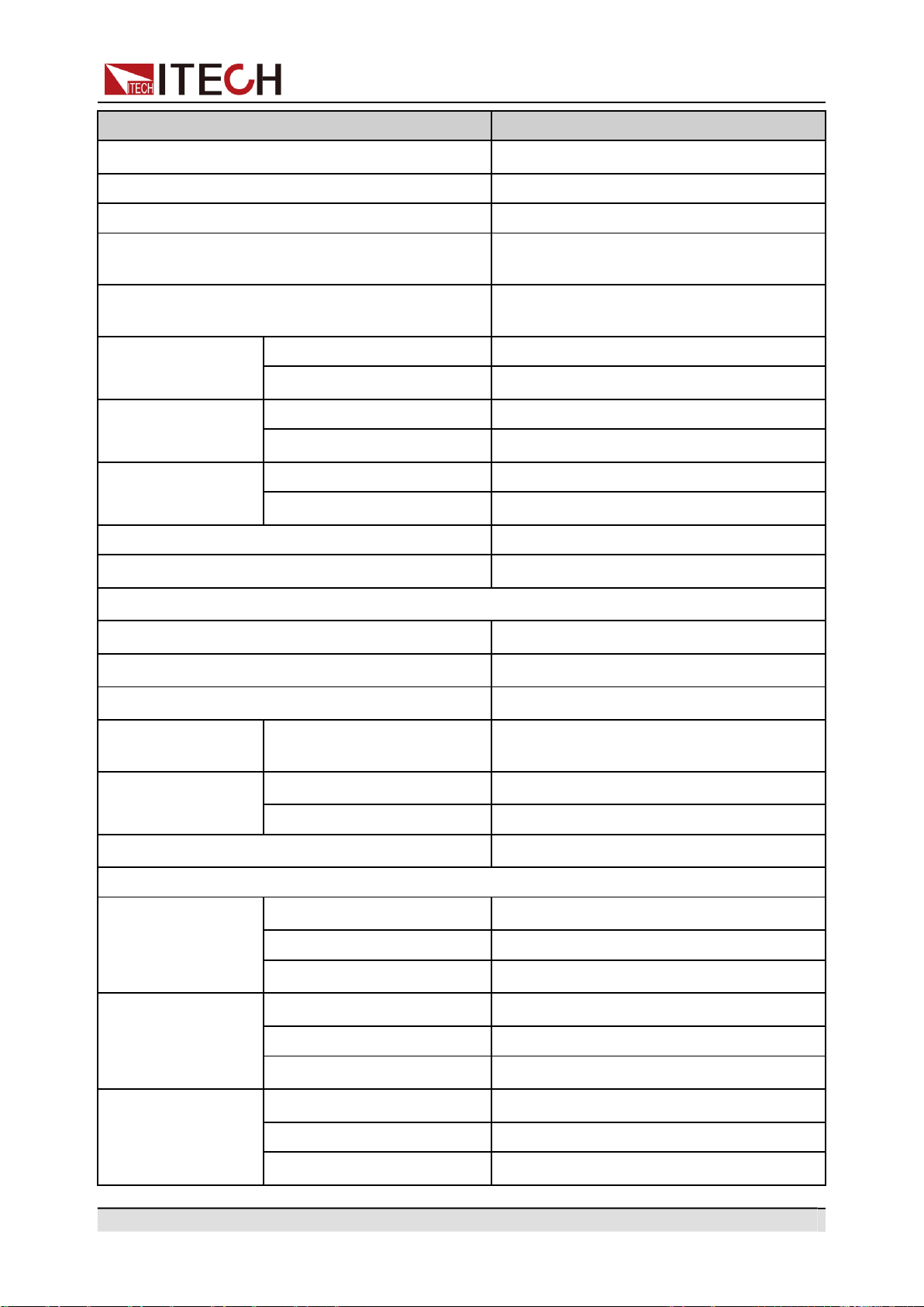
Copyright © Itech Electronic Co., Ltd.
91
Technical Specification
Parameter
IT-M7721L
Phase angle degree range
0–359.9°
THD*2*4
≤0.3% at 45-100Hz
Crest factor
3
Line Regulation *4
≤0.06% (100V±10%) ; ≤0.03% (240V
±10%)
Load Regulation
≤0.13% (100V); ≤0.04% (200V);
≤0.015% (300V)
Output voltage
(VAC)
Resolution
0.1V
Accuracy
±(0.2%×VAC + 0.2%×F.S.)*1
Output frequency
Resolution
0.1Hz
Accuracy
±0.1%
Phase angle de-
gree range
Resolution
0.1°
Accuracy
0.5°
DC offset value
20mV
Efficiency
75% (Typical)
DC Output
Max. output power
300W
Max. output voltage
±400V
Maximum output current (rms)
±3A/±0.75A(±100V/±400V)
Output voltage
(VDC)
Accuracy
±(0.2%×VDC + 0.2%×F.S.) *1
Voltage ripple
Peak- peak
3.2V
RMS
1.27V
Dynamic response time *5
≤0.5ms
Meter
AC Voltage
Range
0-300V
Resolution
0.1V
Accuracy
±(0.25%×VAC + 0.25%×F.S.)*1
AC current (rms)
Range
0.1-3A
Resolution
10mA
Accuracy
±(0.25%×VAC + 0.25%×F.S.)*1
AC current (peak)
Range
0-4.2A
Resolution
10mA
Accuracy
±(0.4%×IP + 0.8%×F.S.)*1
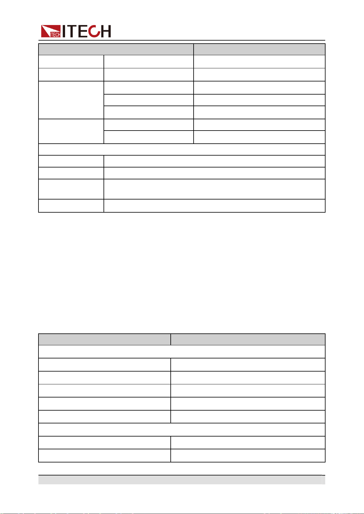
Copyright © Itech Electronic Co., Ltd.
92
Technical Specification
Parameter
IT-M7721L
DC voltage
Accuracy
±(0.25%×VDC + 0.25%×F.S.)*1
DC current
Accuracy
±(0.25%×IDC + 0.25%×F.S.)*1
Frequency
Range
45 - 100Hz
Resolution
0.1Hz
Accuracy
±0.1%*3
Power (S)
Resolution
10mVA
Accuracy
±(0.5%×S + 0.5%×F.S.)*1
Other
Protection
OVP、OCP、OTP、OPP
Interface
GPIB、USBTMC、LAN、RS232
Dimension
(WxHxD)
215 x 44.45(1U) x 450 mm
Weight
4.5Kg
*1: F.S. value is full range.
*2: Min voltage for THD test is 100Vac .
*3: Min voltage for frequency display accuracy is 100Vac.
*4: Tested with pure resistive load.
*5: From 10% to 90% full load.
7.3 IT-M7722
Parameter
IT-M7722
AC Input
Input voltage
100–240Vac (±10%)
Phase
Single-phase
Frequency
47–63Hz
Max. input current
4A/8.5A
Power factor
0.99 (Typical)
AC Output
Max. output power
600VA
Max. output voltage
300V
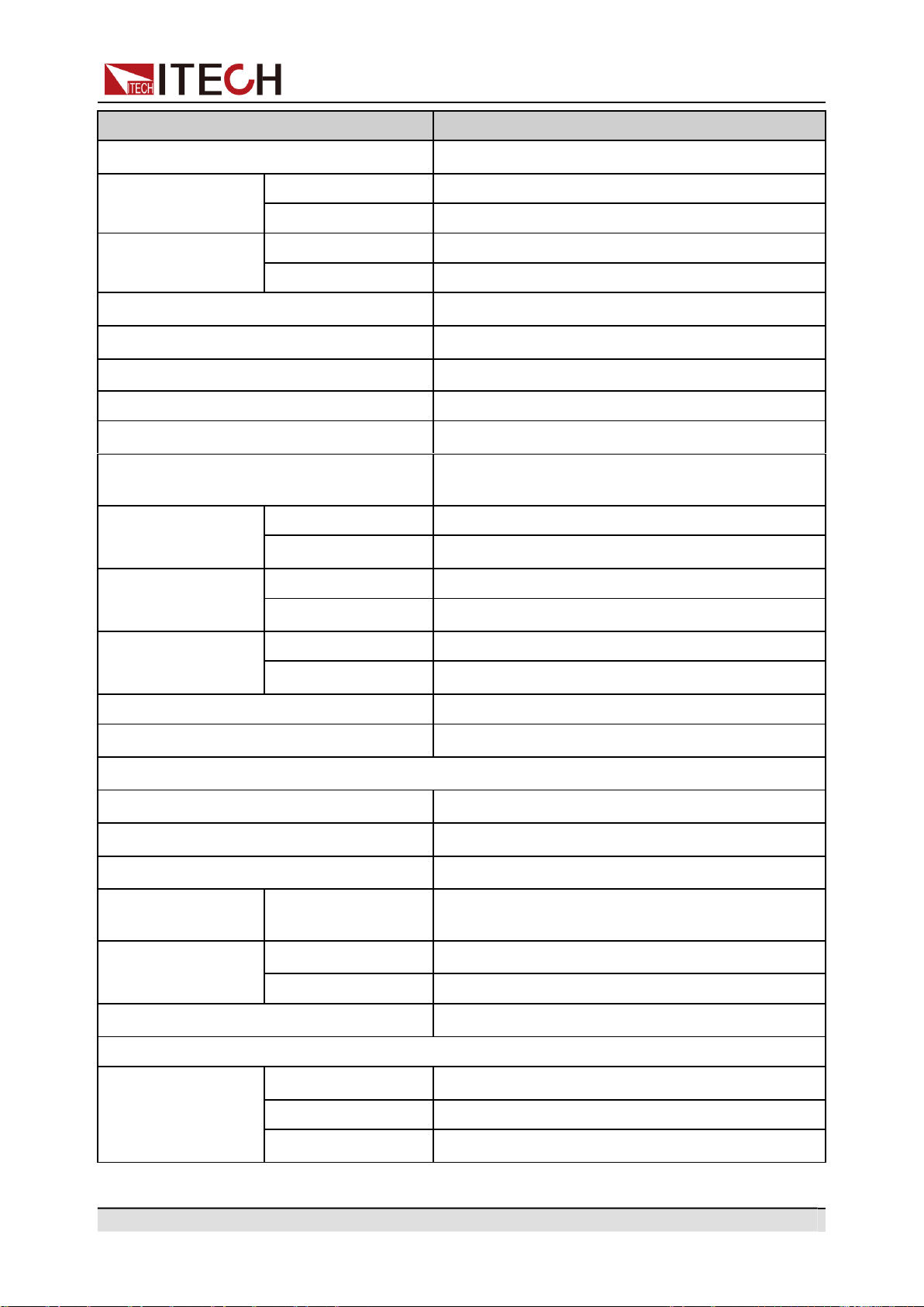
Copyright © Itech Electronic Co., Ltd.
93
Technical Specification
Parameter
IT-M7722
Output phase
Single-phase
Current range(rms)
100V
6A
300V
2A
Current range
(peak)
100V
18A
300V
6A
Output frequency range
45–1000Hz
Phase angle degree range
0–359.9°
THD*2*4
≤0.3% at 45-100Hz; ≤1% at 101-1000Hz
Crest factor
3
Line Regulation *4
≤0.06% (100V±10%) ; ≤0.03% (240V±10%)
Load Regulation
≤0.13% (100V); ≤0.04% (200V); ≤0.015%
(300V)
Output voltage
(VAC)
Resolution
0.1V
Accuracy
±(0.2%×VAC + 0.2%×F.S.)*1
Output frequency
Resolution
0.1Hz
Accuracy
±0.1%
Phase angle degree
range
Resolution
0.1°
Accuracy
0.5°
DC offset value
20mV
Efficiency
80% (Typical)
DC Output
Max. output power
600W
Max. output voltage
±400V
Maximum output current (rms)
±6A/±1.5A(±100V/±400V)
Output voltage
(VDC)
Accuracy
±(0.2%×VDC + 0.2%×F.S.) *1
Voltage ripple
Peak- peak
1.5V
RMS
0.53V
Dynamic response time *5
≤0.5ms
Meter
AC Voltage
Range
0-300V
Resolution
0.1V
Accuracy
±(0.25%×VAC + 0.25%×F.S.)*1
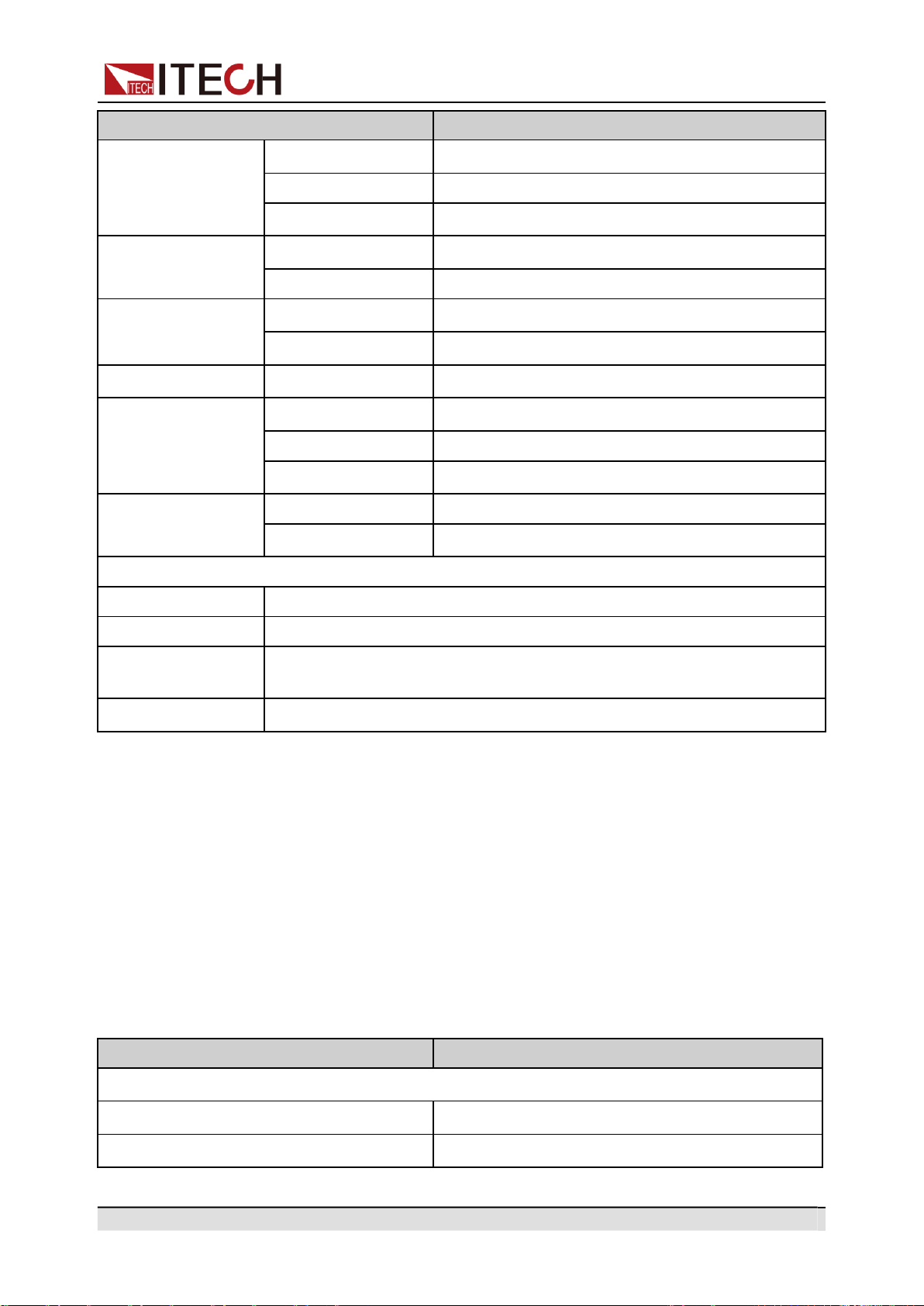
Copyright © Itech Electronic Co., Ltd.
94
Technical Specification
Parameter
IT-M7722
AC current (rms)
Range
0.1-6A
Resolution
10mA
Accuracy
±(0.25%×VAC + 0.25%×F.S.)*1
AC current (peak)
Range
0-8.5A
Resolution
10mA
DC voltage
Accuracy
±(0.4%×IP + 0.8%×F.S.)*1
Accuracy
±(0.25%×VDC + 0.25%×F.S.)*1
DC current
Accuracy
±(0.25%×IDC + 0.25%×F.S.)*1
Frequency
Range
45 - 1000Hz
Resolution
0.1Hz
Accuracy
±0.1%*3
Power (S)
Resolution
10mVA
Accuracy
±(0.5%×S + 0.5%×F.S.)*1
Other
Protection
OVP、OCP、OTP、OPP
Interface
GPIB、USBTMC、LAN、RS232
Dimension
(WxHxD)
215 x 44.45(1U) x 450 mm
Weight
4.5Kg
*1: F.S. value is full range.
*2: Min voltage for THD test is 100Vac .
*3: Min voltage for frequency display accuracy is 100Vac.
*4: Tested with pure resistive load.
*5: From 10% to 90% full load.
7.4 IT-M7722L
Parameter
IT-M7722L
AC Input
Input voltage
100–240Vac (±10%)
Phase
Single-phase
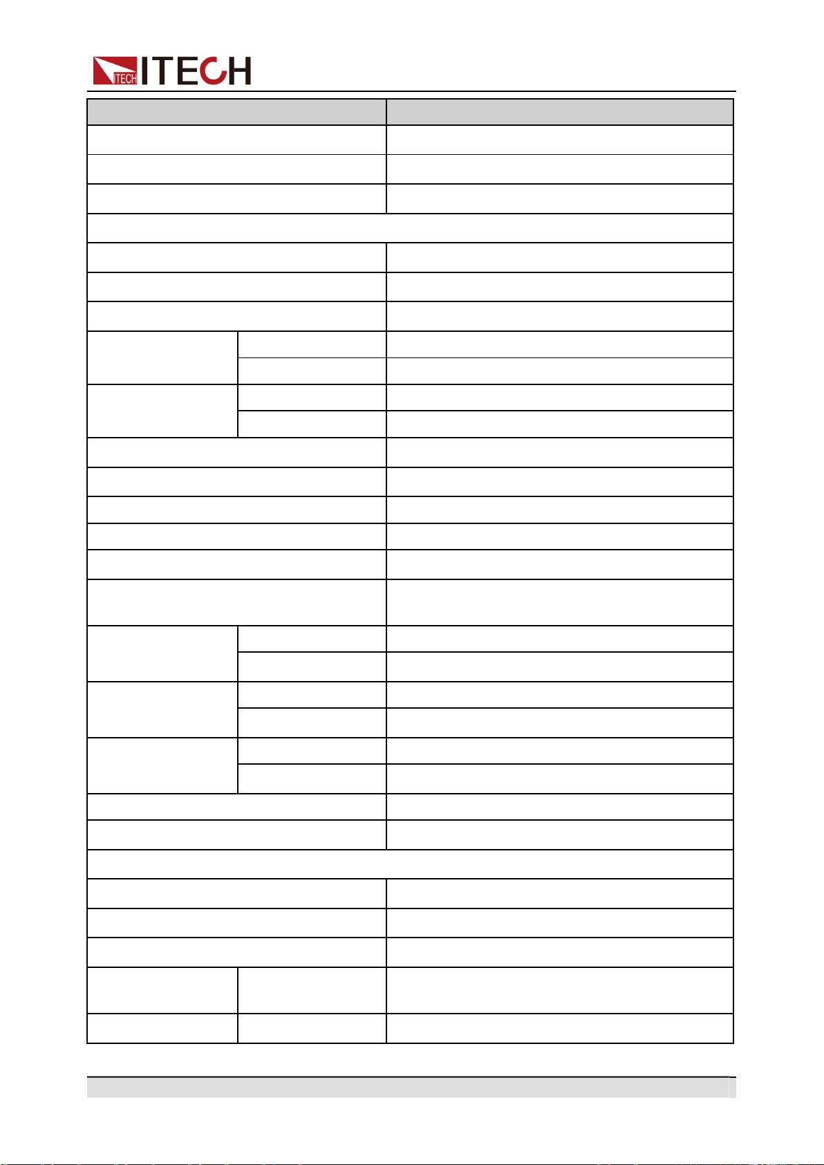
Copyright © Itech Electronic Co., Ltd.
95
Technical Specification
Parameter
IT-M7722L
Frequency
47–63Hz
Max. input current
4A/8.5A
Power factor
0.99 (Typical)
AC Output
Max. output power
600VA
Max. output voltage
300V
Output phase
Single-phase
Current range(rms)
100V
6A
300V
2A
Current range(peak)
100V
18A
300V
6A
Output frequency range
45–100Hz
Phase angle degree range
0–359.9°
THD*2*4
≤0.3% at 45-100Hz
Crest factor
3
Line Regulation *4
≤0.06% (100V±10%) ; ≤0.03% (240V±10%)
Load Regulation
≤0.13% (100V); ≤0.04% (200V); ≤0.015%
(300V)
Output voltage
(VAC)
Resolution
0.1V
Accuracy
±(0.2%×VAC + 0.2%×F.S.)*1
Output frequency
Resolution
0.1Hz
Accuracy
±0.1%
Phase angle degree
range
Resolution
0.1°
Accuracy
0.5°
DC offset value
20mV
Efficiency
80% (Typical)
DC Output
Max. output power
600W
Max. output voltage
±400V
Maximum output current (rms)
±6A/±1.5A(±100V/±400V)
Output voltage
(VDC)
Accuracy
±(0.2%×VDC + 0.2%×F.S.) *1
Voltage ripple
Peak- peak
1.5V
Copyright © Itech Electronic Co., Ltd.
96
Technical Specification
Parameter
IT-M7722L
RMS
0.53V
Dynamic response time *5
≤0.5ms
Meter
AC Voltage
Range
0-300V
Resolution
0.1V
Accuracy
±(0.25%×VAC + 0.25%×F.S.)*1
AC current (rms)
Range
0.1-6A
Resolution
10mA
Accuracy
±(0.25%×VAC + 0.25%×F.S.)*1
AC current (peak)
Range
0-8.5A
Resolution
10mA
Accuracy
±(0.4%×IP + 0.8%×F.S.)*1
DC voltage
Accuracy
±(0.25%×VDC + 0.25%×F.S.)*1
DC current
Accuracy
±(0.25%×IDC + 0.25%×F.S.)*1
Frequency
Range
45 - 100Hz
Resolution
0.1Hz
Accuracy
±0.1%*3
Power (S)
Resolution
10mVA
Accuracy
±(0.5%×S + 0.5%×F.S.)*1
Other
Protection
OVP、OCP、OTP、OPP
Interface
GPIB、USBTMC、LAN、RS232
Dimension (WxHxD)
215 x 44.45(1U) x 450 mm
Weight
4.5Kg
*1: F.S. value is full range.
*2: Min voltage for THD test is 100Vac .
*3: Min voltage for frequency display accuracy is 100Vac.
*4: Tested with pure resistive load.
*5: From 10% to 90% full load.
Copyright © Itech Electronic Co., Ltd.
97
Appendix
A Appendix
Specifications of Red and Black Test Lines
Built -in Waveforms
A.1
Specifications of Red and Black Test Lines
ITECH provides you with optional red and black test lines, which are sold indi-
vidually and you can select for test. For specifications of ITECH test lines and
maximum current values, refer to the table below.
Model
Specification
Cross Section
Length
IT-E301/10A
10A
-
1m
IT-E301/30A
30A
6mm
2
1.2m
IT-E301/30A
30A
6mm
2
2m
IT-E301/60A
60A
20mm
2
1.5m
IT-E301/120A
120A
50mm
2
2m
IT-E301/240A
240A
70mm
2
1m
IT-E301/240A
240A
70mm
2
2m
IT-E301/360A
360A
95mm
2
2m
For maximum current of AWG copper wire, refer to table blow.
AWG
10
12
14
16
18
20
22
24
26
28
The Maxi-
mum Current
Value( A)
40
25
20
13
10
7
5
3.5
2.5
1.7
AWG ( American Wire Gage), it means X wire ( marked on the wire). The table
above lists current capacity of single wire at working temperature of 30°C. For refer-
ence only.
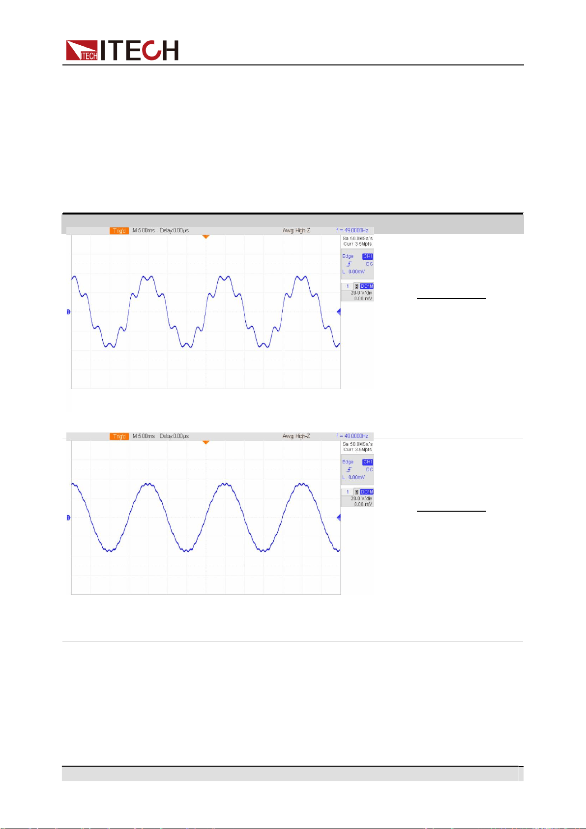
Copyright © Itech Electronic Co., Ltd.
98
Appendix
Waveforms
Component
A.2
Built -in Waveforms
The ITM7700 series power supply is built in with 30 waveforms up to 40 times of
harmonic distortion. The table below lists each time of harmonic component of
each harmonic wave. In the table below, N means the number of harmonic
waves, and % means the percentage of this time of harmonic wave in the base
waveform (1 time) components. The component of other times of harmonic
waves not listed is 0.
THD1
N
%
1
100
2
2.1
5
9.9
7
16
8
2.2
THD2
N
%
1
100
3
1.6
7
1.6
19
2.5
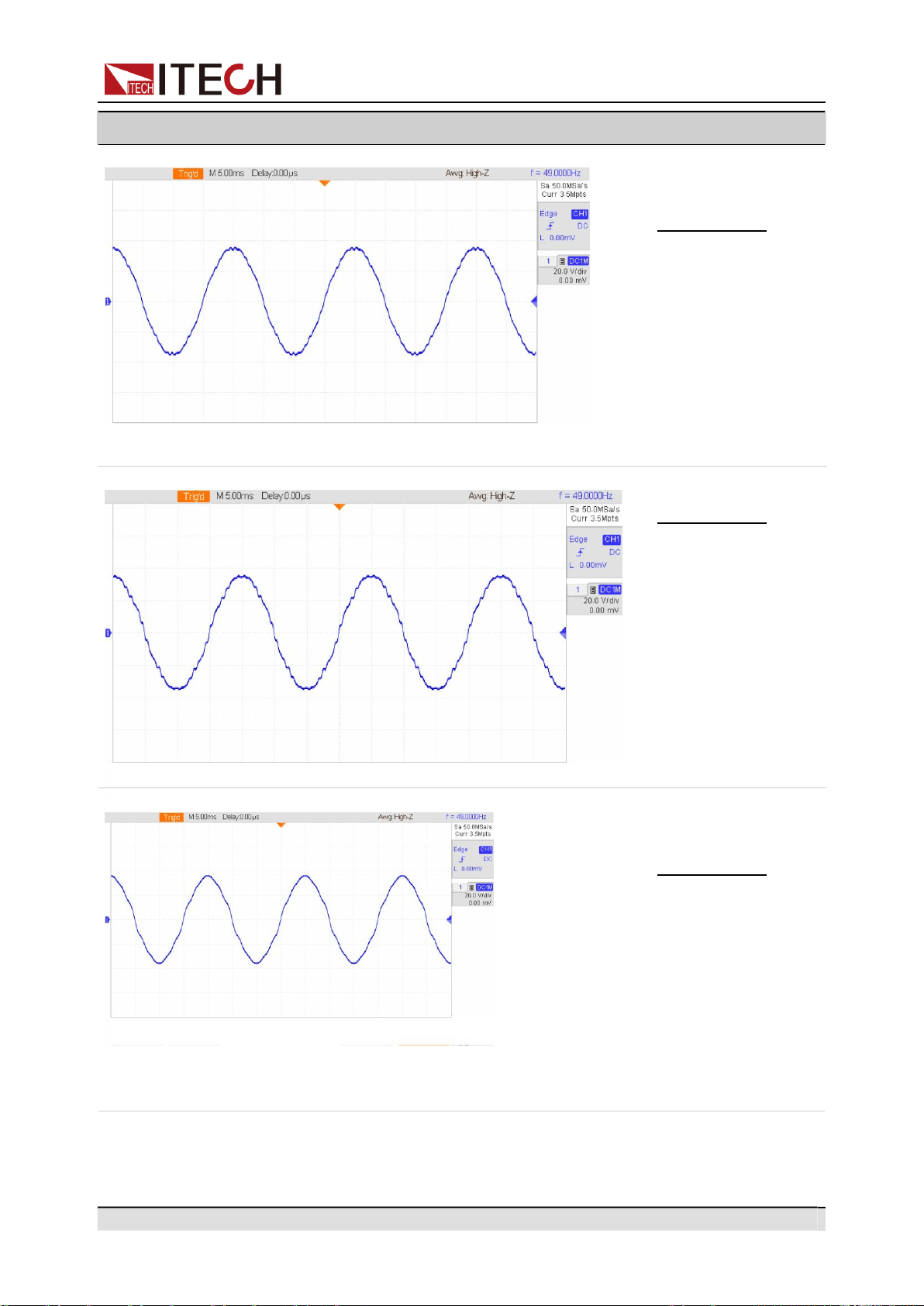
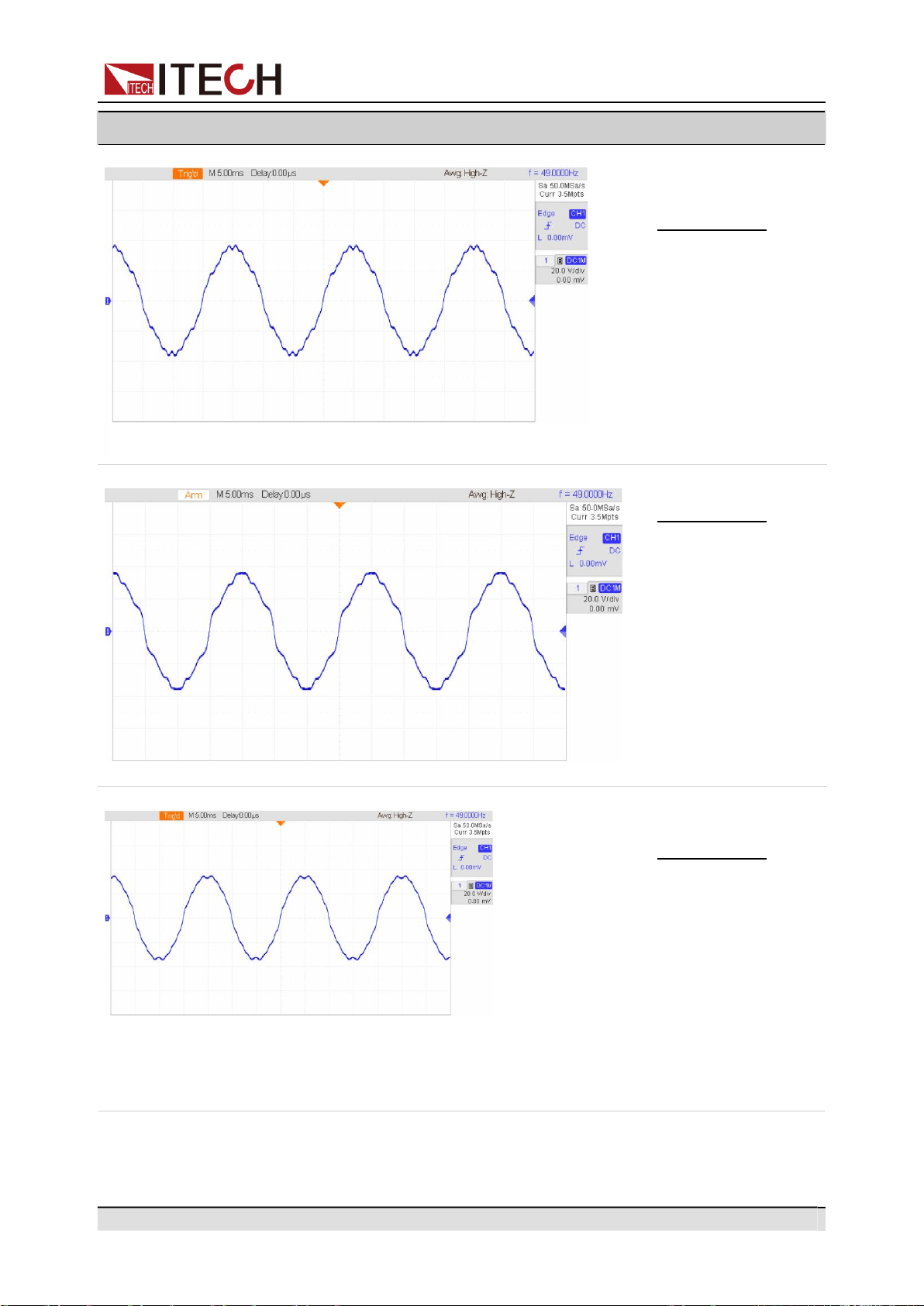
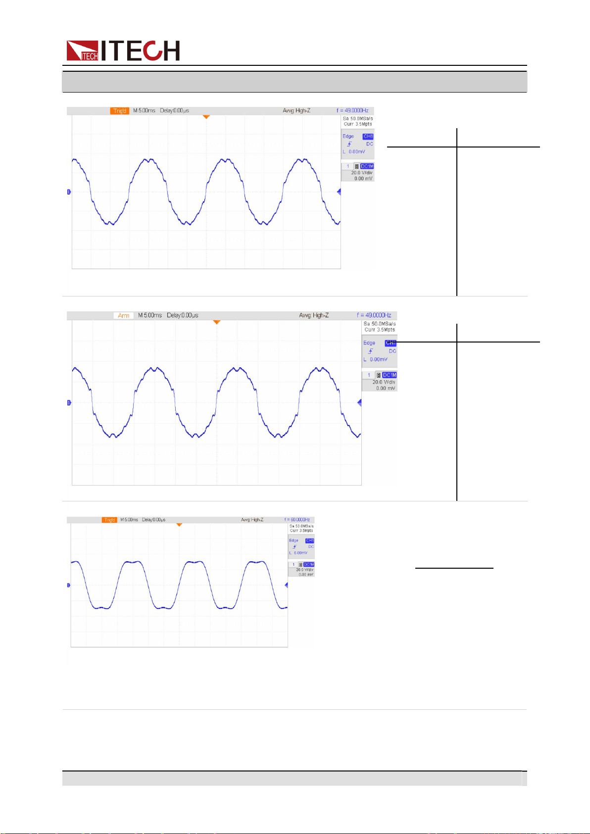
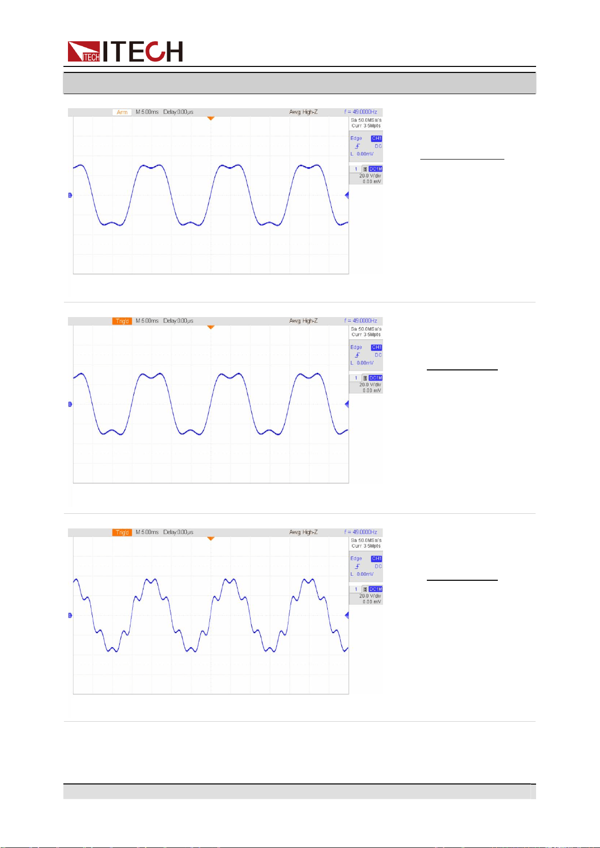
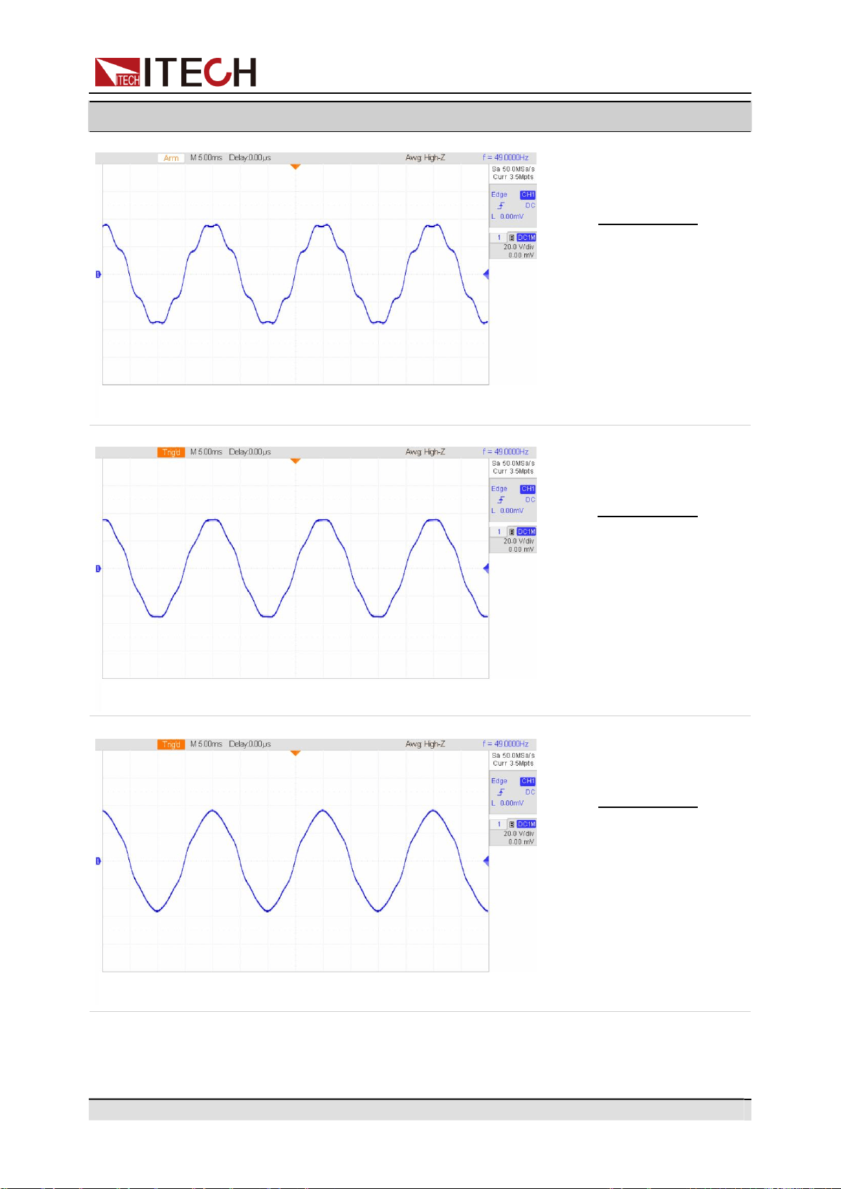
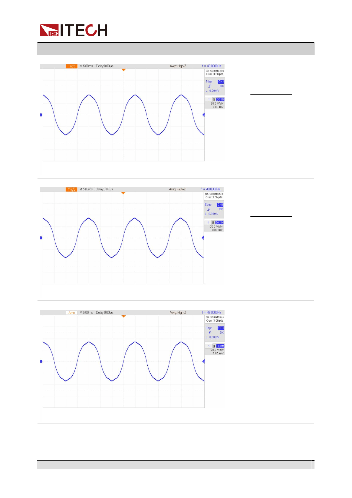
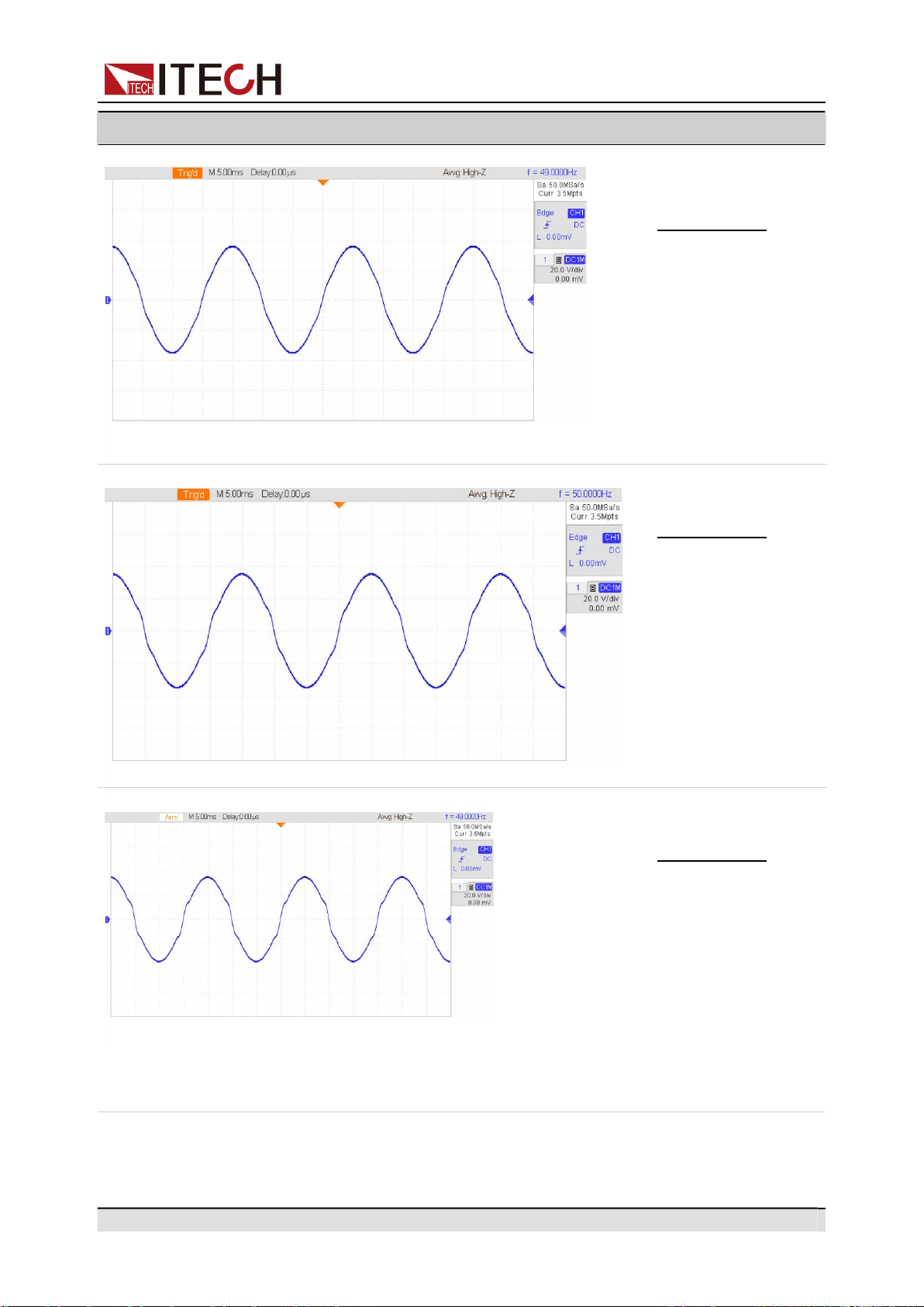
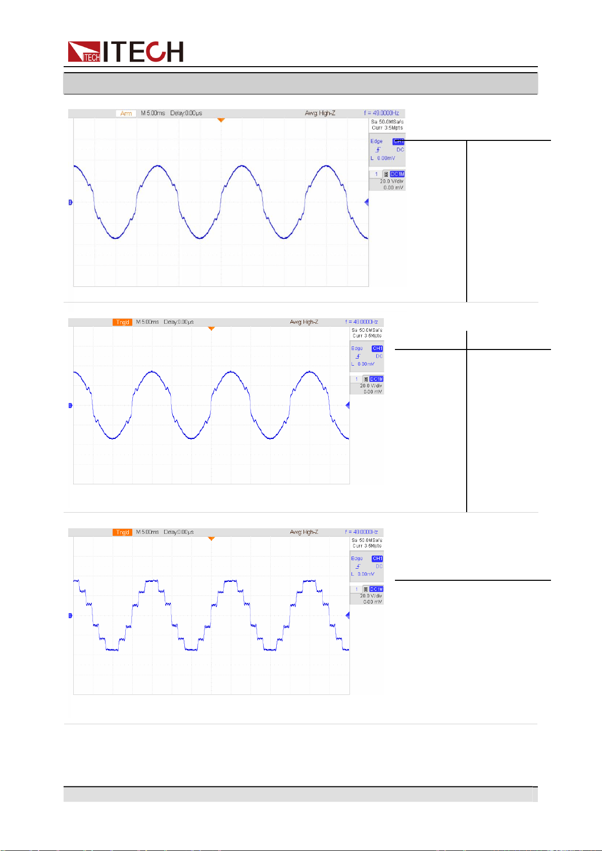
Appendix
Component
Waveforms
Copyright © Itech Electronic Co., Ltd.
106
THD24
N
%
N
%
1
100
15
0.8
3
5.65
21
1.05
5
5.14
23
1.26
7
4.43
25
1.33
9
3.55
27
1.21
11
2.64
29
0.94
13
1.67
THD25
N
%
N
%
1
100
15
1.03
3
7.29
21
1.33
5
6.32
23
1.64
7
5.72
25
1.68
9
4.6
27
1.55
11
3.43
29
1.25
13
2.18
THD26
N
%
N
%
1
100
19
1.03
5
3.55
23
4.13
7
2.67
25
4.15
11
8.88
35
2.62
13
7.85
37
2.85