
Projector
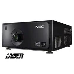
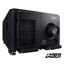
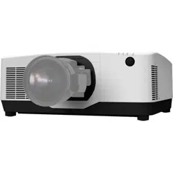
PA1705UL-W/PA1705UL-B
PA1505UL-W/PA1505UL-B
User’s Manual
Model No.
NP-PA1705UL-W/NP-PA1705UL-B/NP-PA1505UL-W/NP-PA1505UL-B

i
Introduction ............................................................................................................................................... ii
Important Information ....................................................................................................................... iii
1. Check the product overview, supplied items and part names .................................... 1
1-1. Introduction to the Projector ............................................................................................................ 1
1-2. What’s in the Box? ................................................................................................................................. 4
1-3. Part Names of the Projector .............................................................................................................. 5
1-4. Part Names of the Remote Control .............................................................................................. 11
2. Projecting an Image (Basic Operation) ................................................................................. 18
2-1. Flow of Projecting an Image .......................................................................................................... 18
2-2. Connecting Your Computer/Connecting the Power Cord .................................................. 19
2-3. Turning on the Projector ................................................................................................................. 22
2-4. Selecting a Source ............................................................................................................................. 25
2-5. Adjusting the Picture Size and Position ..................................................................................... 27
2-6. Adjusting a picture and sound ...................................................................................................... 34
2-7. Turning o the Projector ................................................................................................................. 35
2-8. After Use ................................................................................................................................................ 36
3. Appendix ............................................................................................................................................... 37
3-1. Specications ...................................................................................................................................... 37
3-2. Troubleshooting ................................................................................................................................. 40
3-3. Mounting a lens (sold separately) ................................................................................................ 46
REGISTER YOUR PROJECTOR! (for residents in the United States, Canada, and Mexico)
......... Back cover
Table of Contents

ii
Thank you for purchasing the NEC projector.
This projector can be connected to computers, video devices, etc. to project images sharply onto
a screen.
Please read this manual carefully before using your projector.
Read this manual if you have any doubts about operation or if you believe the projector may be faulty.
The Installation Manual provides detailed instructions on installation, adjustments, maintenance,
etc., is posted on our website.
https://www.sharp-nec-displays.com/dl/en/pj_manual/lineup.html
Ver. 1 7/23
NOTES
(1) The contents of this manual may not be reprinted in part or whole without permission.
(2) The contents of this manual are subject to change without notice.
(3) Great care has been taken in the preparation of this manual; however, should you notice any
questionable points, errors or omissions, please contact us.
(4) The image shown in this manual is indicative only. If there is inconsistency between the image
and the actual product, the actual product shall govern.
(5) Notwithstanding article (3) and (4), we will not be responsible for any claims on loss of prot or
other matters deemed to result from using this device.
(6) This manual is commonly provided to all regions so they may contain descriptions that are
pertinent for other countries.
Introduction
iii
About the symbols
To ensure safe and proper use of the product, this manual uses a number of symbols to prevent
injury to you and others as well as damage to property.
The symbols and their meanings are described below. Be sure to understand them thoroughly
before reading this manual.
WARNING
Failing to heed this symbol and handling the product erroneously
could result in accidents leading to death or major injury.
CAUTION
Failing to heed this symbol and handling the product erroneously
could result in personal injury or damage to surrounding property.
Examples of symbols
This symbol indicates you should be careful of electric shocks.
This symbol indicates you should be careful of high temperatures.
This symbol indicates something that must be prohibited.
This symbol indicates something that must not be got wet.
This symbol indicates you should not touch with wet hands.
This symbol indicates something that must not be disassembled.
This symbol indicates things you must do.
This symbol indicates that the power cord should be unplugged from the power outlet.
Important Information
Important Information
iv
Safety Cautions
WARNING
Projected light
Projected light and the pictogram/label indicated on the cabinet
PROHIBITED
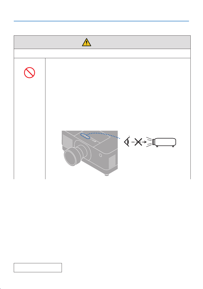
• Do not look into the projector’s lens.
Strong light that could damage your vision is projected when the projec-
tor is operating. Laser energy exposure near aperture may cause burns. Be
especially careful when children are around.
• Do not look at the projected light using optical devices (magnifying glasses,
reectors, etc.). Doing so could result in vision impairment.
• Check that there is no one looking at the lens within the projection range
before turning on the projector.
• Do not allow children to operate the projector alone. When a child is operating
the projector an adult should always be present and watch the child carefully.
• The below pictogram, that is indicated near the lens on the cabinet, describes
looking into the projector is prohibited.
Continue to next page
Important Information
v
WARNING
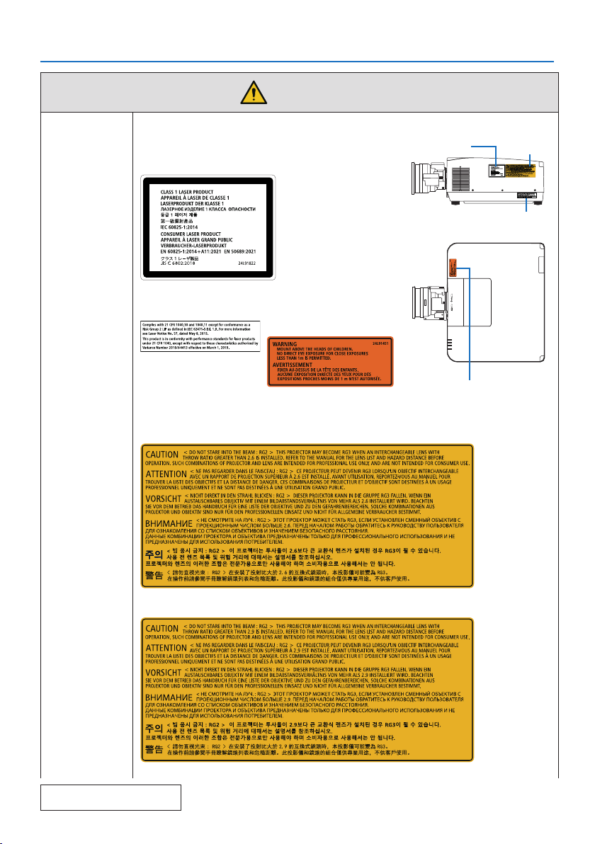
• The following labels are stuck on the projector.
Label 1
Laser explanatory label
This product complies
with EN 50689:2021
except using the lens
of NP55ZL and NP56ZL.
Label 1
Label 2
Label 4
Label 3
Label 2
FDA certication label
Label 3
FDA additional warning
label
Label 4
Lens replacement caution label
PA1705UL-W/PA1705UL-B
PA1505UL-W/PA1505UL-B
Continue to next page
Important Information
vi
WARNING
• This projector is classied as either IEC/EN 62471-5:2015 risk group 2 or risk
group 3 depending on the lens unit.
When classied as risk group 3, this projector is intended for professional use
and must be installed by professional installer to ensure safety.
See page xv for risk groups.
• See page xiv for Laser Safety Caution.
Power supply
Use a suitable voltage power supply.
REQUIRED
• This projector is designed to be used with a 100–240 V AC, 50/60 Hz power
supply. Before using the projector, check that the power supply to which the
projector is to be connected meets these requirements.
• Use a power outlet as the projector’s power supply. Do not connect the
projector directly to electrical light wiring. Doing so is dangerous.
Connecting the power cord to earth
REQUIRED
• This equipment is designed to be used in the condition of the power cord
connected to earth. If the power cord is not connected to the earth, it may
cause electric shock. Please make sure the power cord is connected to the
wall outlet directly and earthed properly.
Do not use a 2-pin plug converter adapter.
• Be sure to connect the projector and the computer (signal source) to the
same earth point. If the projector and the computer (signal source) will be
connected to dierent earth points, uctuations in the earth potential may
cause re or smoke.
Handling the power cord
REQUIRED
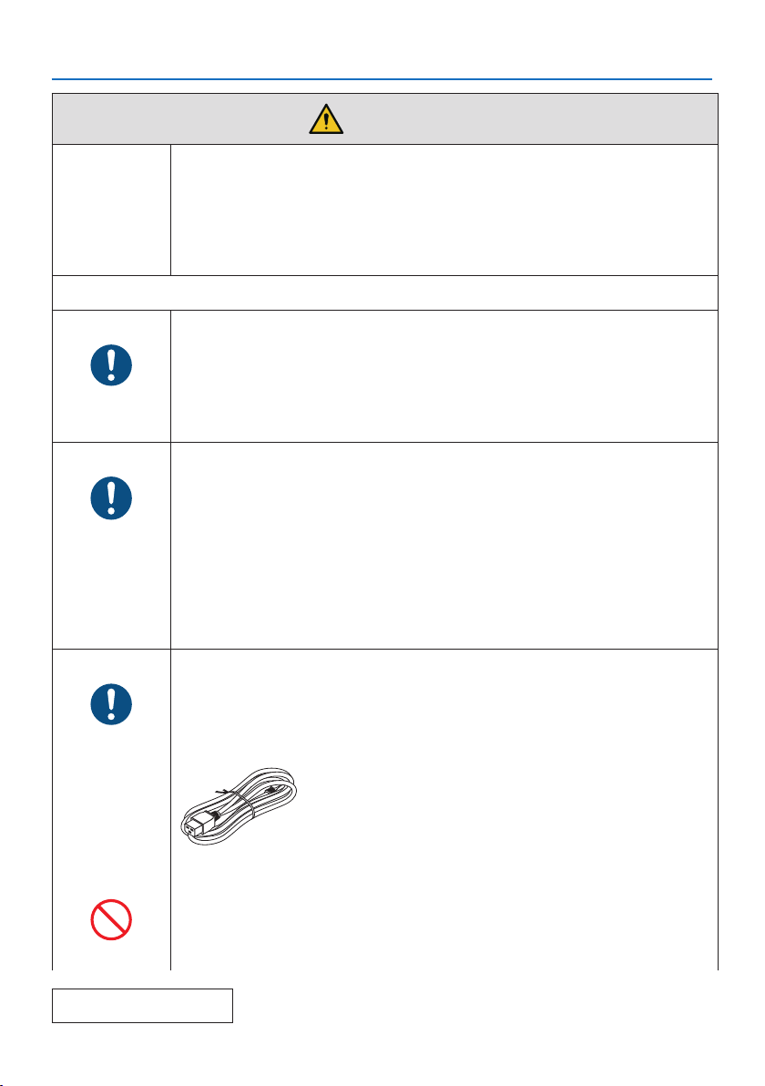
• Please use the power cord supplied with this projector. If the supplied power
cord does not satisfy requirements of your country’s safety standard, and
voltage and current for your region, make sure to use the power cord that
conforms to and satises them.
• The power cord you use must be approved by and
comply with the safety standards of your country.
Please refer to the page 38 about the power cord
specication.
For selecting an appropriate power cord, please check
rated voltage for your region by yourself.
PROHIBITED
• The power cord included with this projector is exclusively for use with this
projector. For safety, do not use it with other devices.
Continue to next page
Important Information
vii
WARNING
HAZARDOUS
VOLTAGE
• Handle the power cord with care. Damaging the cord could lead to re or
electric shock.
- Do not place heavy objects on the cord.
- Do not place the cord under the projector.
- Do not cover the cord with a rug, etc.
- Do not scratch or modify the cord.
- Do not bend, twist or pull the cord with excessive force.
- Do not apply heat to the cord.
Should the cord be damaged (exposed core wires, broken wires, etc.), ask
your dealer to replace it.
• Do not touch the power plug should you hear thunder. Doing so could result
in electric shock.
DO NOT TOUCH
WITH WET
HANDS
• Do not connect or disconnect the power cord with wet hands. Doing so could
result in electric shock.
Installation
Do not use in places such as those described below.
PROHIBITED
• Do not use in places such as those described below. Doing so could lead to
re or electric shock.
- Shaky tables, inclined surfaces or other unstable places
- Near heating appliances or places with heavy vibrations
- Outdoors or humid or dusty places
- Places exposed to oil smoke or steam
- Near cooking appliances, humidiers, etc.
DO NOT WET
• Do not use in places such as those described below where the projector could
get wet. Doing so could lead to re or electric shock.
- Do not use in the rain or snow, on a seashore or waterfront, etc.
- Do not use in a bathroom or shower room.
- Do not install under equipment that discharges water, such as air condition-
ers.
- Do not place vases or potted plants on the projector.
- Do not place cups, cosmetics or medicines on the projector.
Should water, etc. get inside the projector, rst turn o the projector’s power,
then unplug the power cord from the power outlet and contact your dealer.
UNPLUG THE
POWER CORD
Important Information
viii
WARNING
Installing suspended from the ceiling
CAUTION
• Consult your dealer for installing the projector on the ceiling. Special skills
are required for ceiling installation.
DO NOT perform installation work by people other than installers. Doing so
may result in the projector falling and causing injury.
• We are not liable for any accident or/and damage resulting from improper
installation or handling, misuse, modication, or natural disasters.
• When installed suspended from the ceiling, etc. do not hang from the projec-
tor. The projector could drop and cause injury.
• When installing suspended from the ceiling, use a power outlet that is within
reach so the power cord can be easily plugged and unplugged.
Attach the separately sold option cover for tilted installation
REQUIRED
• For tilted installation of the projector, depending on the angle, be sure to at-
tach the separately sold option cover for safety. (→ page xxvi) Using without
the option cover violates safety regulations. Also, powering the projector on
without the option cover installed could result in a re.
• Do not put bundled cables in the option cover. Doing so may damage the
power cord, resulting in a re.
PROHIBITED
On use
Do not place objects inside the projector.
PROHIBITED
• Do not insert or drop metal or combustible objects or other foreign materials
into the projector from the vents. Doing so could lead to re or electric shock.
Be particularly careful if there are children in the home. Should a foreign object
get inside the projector, rst turn o the projector’s power, then unplug the
power cord from the power outlet and contact your dealer.
UNPLUG THE
POWER CORD
Unplug the power cord if the projector malfunctions.
UNPLUG THE
POWER CORD
• Should the projector emit smoke or strange odors or sounds, or if the projec-
tor has been dropped or the cabinet broken, turn o the projector’s power,
then unplug the power cord from the power outlet. It may cause not only re
or electric shock but also serious damage to your eyesight or burns. Contact
your dealer for repairs.
Never try to repair the projector on your own. Doing so is dangerous.
Important Information
ix
WARNING
Do not disassemble the projector.
DO NOT
DISASSEMBLE
• Do not remove or open the projector’s cabinet.
Also, do not modify the projector. There are high voltage areas in the projec-
tor. It may cause re, electric shock, or laser light leakage, resulting in serious
damage to your eyesight or burns.
Have qualied service personnel perform inspection, adjustments and repairs
of the interior.
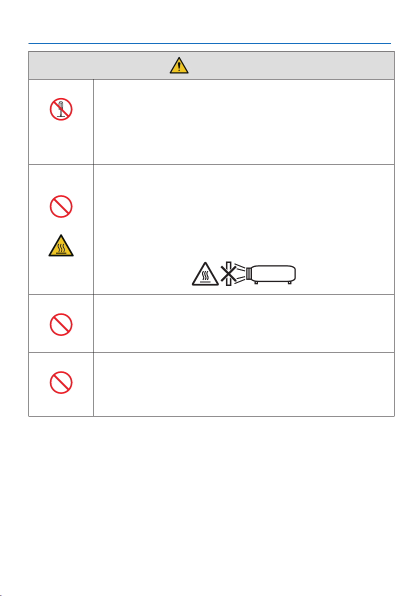
Do not place objects in front of the lens while the projector is
operating.
PROHIBITED
• Do not leave the lens cap on the lens while the projector is operating. The
lens cap could get hot and be warped.
• Do not place objects in front of the lens that obstruct the light while the
projector is operating. The object could get hot and be broken or catch re.
• The below pictogram indicated on the cabinet means the precaution for
avoiding to place objects in front of the projector lens.
CAUTION
FOR HIGH
TEMPERATURE
When cleaning the projector
PROHIBITED
• Do not use ammable gas sprays to remove dust from the lens, cabinet, etc.
Doing so could lead to re.
Do not use in high security locations.
PROHIBITED
• Usage of the product must not be accompanied by fatal risks or dangers that,
could lead directly to death, personal injury, severe physical damage or other
loss, including nuclear reaction control in nuclear facility, medical life support
system, and missile launch control in a weapon system.
Important Information
x
CAUTION
Power cord
Handling the power cord
REQUIRED
• The projector should be installed close to an easily accessible power outlet.
• When connecting the power cord to the projector’s AC IN terminal, make sure
the connector is fully and rmly inserted. Be sure to x the power cord using
the power cord stopper. Loose connection of the power cord could lead to
re or electric shock.
Handling the power cord by following below to avoid re or
electric shock
REQUIRED
UNPLUG THE
POWER CORD
• When connecting or disconnecting the power cord, pull the power cord out
by holding onto its plug.
• Unplug the power cord from the power outlet before cleaning the product
or when not planning to use the product for an extended time.
• When the power cord or plug is heat or damaged, unplug the power cord
from the power outlet, and contact your dealer.
Periodically clean dust and other debris from the power plug
REQUIRED
• Failure to do so could result in re or electric shock.
Disconnect power cords and other cables before moving the
projector
REQUIRED
• Before moving the product, make sure the product power is o, then unplug
the power cord from the power outlet and check that all cables connecting
the product to other devices are disconnected.
Do not use the power cord with a power tap
PROHIBITED
• Adding an extension cord may lead to re as a result of overheating.
Important Information
xi
CAUTION
Installation
Securing the lens unit with the fall prevention wire
REQUIRED
• If the projector is going to be suspended from a ceiling or another high place,
secure the lens unit using the fall prevention wire (sold separately). If the lens
unit is not secured, it may fall down if it comes lose.
On use
Do not use on networks subject to overvoltage.
PROHIBITED
• Connect the projector’s HDBaseT port and LAN port to a network for which
there is no risk of overvoltage being applied.
Overvoltage applied to the HDBaseT or LAN port could result in electric shock.
Lens shift, focus and zoom operations
REQUIRED
• When shifting the lens or adjusting the focus or zoom, do so from either
behind or the side of the projector. If adjustments are performed from the
front, your eyes could be exposed to strong light and get injured.
• Keep your hands away from the lens area when performing the lens shift op-
eration. If not, your ngers could get caught in the gap between the cabinet
and the lens.
Important Information
xii
CAUTION
Handling batteries
PROHIBITED
Incorrect usage of batteries can result in leaks or bursting.
• Use the specied batteries only.
• Insert batteries matching the (+) and (–) signs on each battery to the (+) and
(–) signs of the battery compartment.
• Do not mix battery brands.
• Do not combine new and old batteries. This can shorten battery life or cause
liquid leakage of batteries.
• Remove dead batteries immediately to prevent battery acid from leaking into
the battery compartment.
If leaked battery uid gets on your skin or clothing, rinse immediately and
thoroughly. If it gets into your eye, bathe your eye well rather than rubbing
and seek medical treatment immediately. Leaked battery uid that gets into
your eye or your clothing may cause a skin irritation or damage your eye.
• If you will not use the remote control for a long time, remove the batteries.
• Leaving a battery in an extremely high temperature surrounding environ-
ment, or a battery subject to extremely low air pressure, that can result in an
explosion or the leakage of ammable liquid or gas.
• Properly dispose of depleted batteries. Disposal of a battery into water, re,
or a hot oven, or mechanically crushing, cutting, or modifying a battery can
result in an explosion.
• Do not short-circuit the batteries.
• Do not charge the batteries. The batteries provided are not rechargeable.
• Contact your dealer or local authorities when disposing of batteries.
About the vents
PROHIBITED
• Do not obstruct the projector’s vents. Also, do not place such soft objects as
paper or cloths underneath the projector. Doing so could lead to re.
Leave sucient space between the place where the projector is installed and
its surroundings. (→ page xxix)
• Do not touch the exhaust vent area while projecting or immediately after
projecting images. The exhaust vent area may be hot at this time and touch-
ing it could cause burns.
CAUTION
FOR HIGH
TEMPERATURE
Important Information
xiii
CAUTION
Moving the projector
PROHIBITED
• When carrying the projector, remove the lens unit and carry it with at least
two people. Attempting to move the projector alone could result in back pain
or other injuries.
• When carrying the projector with the lens unit removed, do not touch the
mounting area of the lens with your hands. Also, do not put your hand into
the recess of the connection terminal. The projector could be damaged or
fall down, resulting in injuries.
• When moving the projector with the option cover attached, do not hold it by
the option cover. The option cover could come lose and the main unit could
fall down, causing injuries.
Attaching/detaching the lens
REQUIRED
• Turn o the projector and disconnect the power cord before attaching or
detaching the lens unit. Failure to do so could result in visual impairment or
burns.
• Do not attach or detach the lens unit with the projector installed in a high
location.
The lens unit could fall and cause damage or injury.
About option cover (separately sold)
REQUIRED
• Be sure to tighten the screws after attaching the option cover. Failure to do so
may cause the option cover to come o and fall, resulting in injury or damage
to the option cover.
PROHIBITED
• Do not hold the option cover while moving the projector or do not apply
excessive force to the option cover. Doing so may damage the option cover,
resulting in injury.
Avoid locations with extreme temperatures and humidity
REQUIRED
• Failure to do so could lead to re or electric shock or damage to the projector.
The usage environment for this projector is as follows:
- The operating temperature: 0°C to 45°C / 32°F to 113°F / humidity: 20 to
80% (without condensation)
- The storage temperature: -10°C to 50°C / 14°F to 122°F / humidity: 20 to
80% (without condensation)
Inspections and Cleaning
Inspecting the projector and cleaning the inside
REQUIRED
• Consult with your dealer about once per year for cleaning of the inside of the
projector. Dust could accumulate inside of the projector if it is not cleaned
for extended periods of time, leading to res or malfunction.
Important Information
xiv
Laser Safety Caution
WARNING
CLASS 1 LASER PRODUCT [IEC 60825-1:2014]
CLASS 1 CONSUMER LASER PRODUCT OF EN 60825-1:2014+A11:2021 (For EU and UK)
• The laser module is equipped in this product. Use of controls or adjustments of procedures
other than those specied herein may result in hazardous radiation exposure.
Laser energy exposure near aperture may cause burns.
• This product is classied as Class 1 of IEC 60825-1:2014.
• For EU and UK, EN 60825-1:2014+A11:2021 and EN 50689:2021 are also conformed.
Except using the lens of NP55ZL and NP56ZL.
• Obey the laws and regulations of your country in relation to the installation and management of
the device.
For USA
Complies with 21 CFR 1040.10 and 1040.11 except for conformance as a Risk Group 2 LIP as
dened in IEC 62471-5:Ed. 1.0. For more information see Laser Notice No. 57, dated May 8, 2019.
However, when using the NP55ZL and NP56ZL lenses, the following applies.
This product is in conformity with performance standards for laser products under 21 CFR 1040,
except with respect to those characteristics authorized by Variance Number 2018-V-4413 eec-
tive on March 1, 2019.
WARNING
• Do not allow to look into the projector beam at any distance from the projector. An adult
should supervise the children to prevent exposure risks.
• Check that there is no one looking at the lens, when using the remote control for starting the
projector.
• Do not look at the projected light using optical devices(binoculars, telescopes, magnifying
glasses, reectors, etc).
• [ WARNING: MOUNT ABOVE THE HEADS OF CHILDREN. ]
The use of a ceiling mount is recommended with this product to place it above the eyes of
children.
• Outline of laser emitted from the built-in light module:
- Wave length: 455 nm
- Maximum power: 390 W (PA1705UL-W/PA1705UL-B), 346 W (PA1505UL-W/PA1505UL-B)
Light Module
• A light module containing multiple laser diodes is equipped in the product as the light source.
• These laser diodes are sealed in the light module. No maintenance or service is required for the
performance of the light module.
• End user is not allowed to replace the light module.
• Contact qualied distributor for light module replacement and further information.
Important Information
xv
Risk groups
This projector is classied as either IEC/EN 62471-5:2015 risk group 2 or risk group 3 depending
on the lens unit.
Risk group 2 (RG2)
WARNING
As with any bright light source, do not stare into the beam, RG2 IEC/EN 62471-5:2015.
Risk group 3 (RG3)
WARNING
RG3 PRODUCT OF IEC/EN 62471-5:2015
• When classied as RG3, this projector is for professional use and must be installed in location
where safety is assured. For this reason, be sure to consult your dealer as installation must be
performed by a professional installer. Never try to install the projector by yourself. This may
result in visual impairment etc.
• No direct exposure to the beam shall be permitted, RG3 IEC/EN 62471-5:2015.
• Do not look into the projector’s lens. Serious damage to your eyes could result.
• Operators shall control access to the beam within the hazard distance or install the product
at the height that will prevent exposures of spectators’ eyes within the hazard distance.
• When turning on the power, operate from the side or rear of the projector (outside the hazard
zone). Also, when turning on the power, make sure no one within the projection range is look-
ing at the lens.
Important Information
xvi
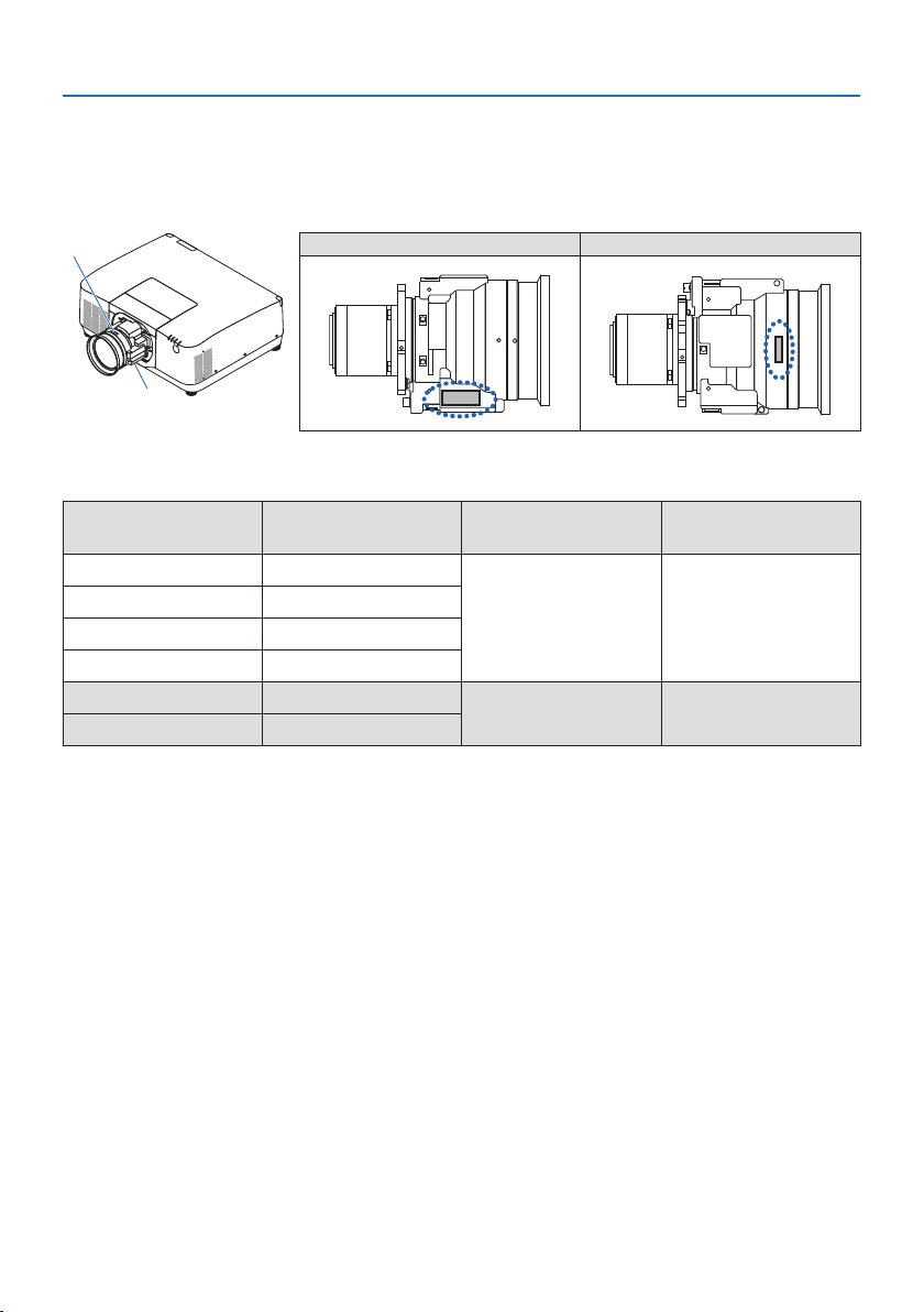
• Check before installing the projector
① Lens model name or throw ratio
The lens model name and throw ratio are listed in the image below.
a
b
a: Lens model name b: Throw ratio
② Combining lens units and risk groups
Lens model name Throw ratio
PA1705UL-W
PA1705UL-B
PA1505UL-W
PA1505UL-B
NP51ZL 0.53 - 0.65
RG2 RG2
NP52ZL 0.65 - 0.87
NP53ZL 0.86 - 1.25
NP54ZL 1.24 - 2.01
NP55ZL 1.98 - 3.95
RG3 RG3
NP56ZL 3.92 - 7.50
Important Information
xvii
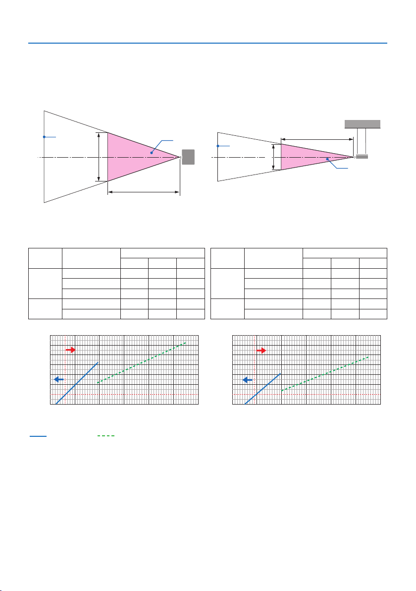
• Hazard zone
The below gure describes the radiation zone (hazard zone) of light emitted by the projector that
is classied as Risk Group 3 (RG3) of IEC/EN 62471-5:2015.
Overhead view Side view
H
a
b
HD
HD
V
a
b
a: Screen / b: Hazard zone
PA1705UL-W/PA1705UL-B PA1505UL-W/PA1505UL-B
Lens Throw ratio
Hazard zone (m)
HD H V
NP55ZL
1.98 (Wide) - - -
2.60 (Middle) 1.00 0.4 0.3
3.95 (Tele) 1.65 0.5 0.3
NP56ZL
3.92 (Wide) 1.23 0.3 0.2
7.50 (Tele) 2.04 0.3 0.2
Lens Throw ratio
Hazard zone (m)
HD H V
NP55ZL
1.98 (Wide) - - -
2.90 (Middle) 1.00 0.4 0.2
3.95 (Tele) 1.43 0.4 0.3
NP56ZL
3.92 (Wide) 1.06 0.2 0.2
7.50 (Tele) 1.75 0.2 0.2
2.0 3.0
2.6
4.0 5.0 6.0 7.0 8.0
0.8
1.0
1.2
1.4
1.6
1.8
2.0
2.2
HD [m]
0.8
1.0
1.2
1.4
1.6
1.8
2.0
2.2
HD [m]
2.0 3.0 4.0 5.0 6.0 7.08.0
2.9
RG3
RG3
RG3
RG2
RG2
RG2
RG3
RG3
RG3
RG2
RG2
RG2
Throw ratio Throw ratio
NP55ZL NP56ZL (Provisional value)
Calculation of the throw ratio
Throw ratio = L: Throw distance (m) / W: Screen width (m)
For throw distances and screen widths, refer to “Lens types and throw distance” in the installation
manual.
Important Information
xviii
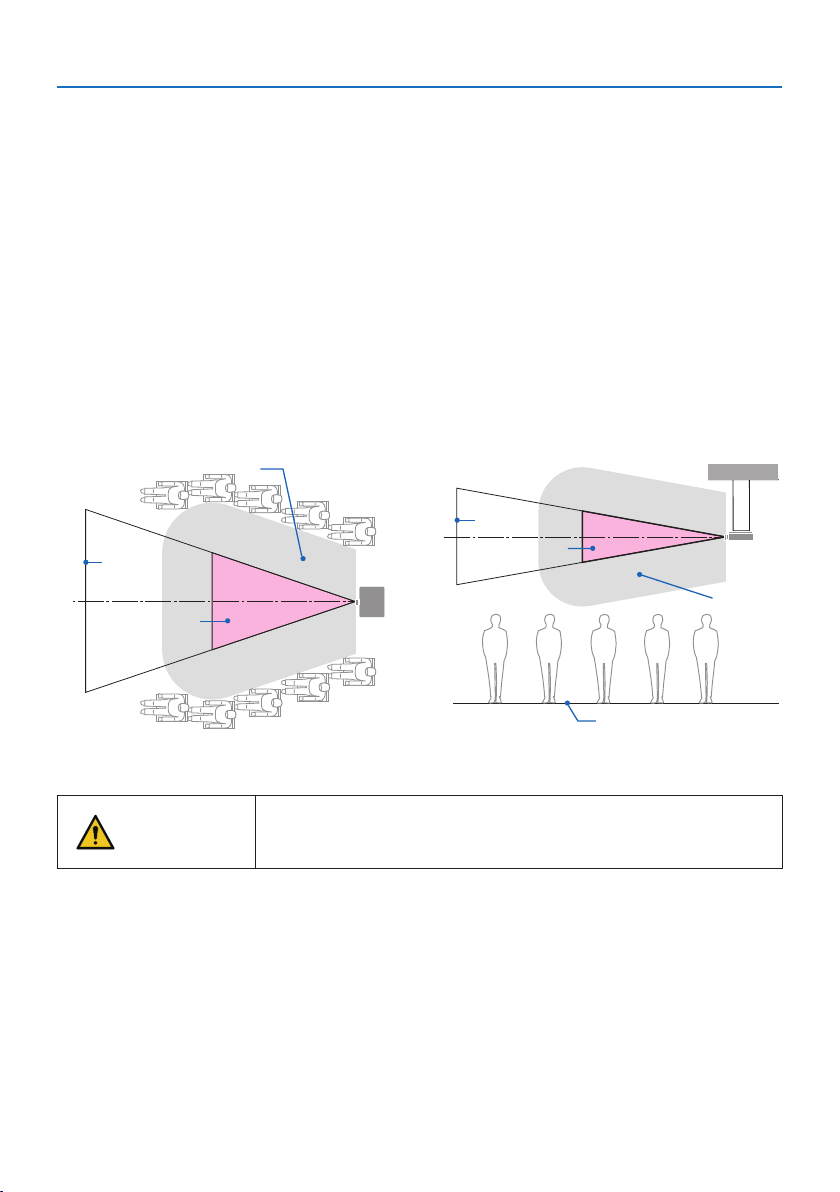
• About the precautionary zone
By providing a precautionary zone or physical barriers, it is possible to prevent human eyes from
entering the hazard zone.
When the manager of the projector (operator) cannot prevent spectators from entering the hazard
zone such as in public facilities, it is recommended to secure a space of 1 m or more from the haz-
ard zone as “the precautionary zone” for the safety of the spectators. When installing the projector
overhead, it is recommended that the distance between the oor and the hazard zone be at least
3 m in the vertical direction.
In the United States, provide a horizontal distance of 2.5 meters from the hazard zone.
When installthe projector overhead, provide a vertical distance of 3 meters from the oor to the
hazard zone.
• Installation example considering the precautionary zone
① Floor or desktop installation example
a
b
c
② Ceiling installation example
a
b
d
c
a: Screen / b: Hazard zone / c: Precautionary zone / d: oor
CAUTION
If it is expected that spectators will intrude into the hazard zone when
installed on the ceiling, it is necessary to prevent spectators from
entering that area.
Important Information
xix
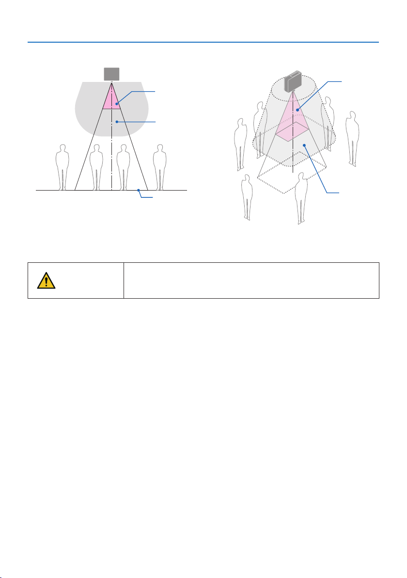
③ Example of downward projection installed on the ceiling
b
d
c
b
d
c
a: Screen / b: Hazard zone / c: Precautionary zone / d: oor
CAUTION
If the precautionary zone between the oor and the hazard zone can-
not be secured, it is necessary to prevent spectators from entering the
area around the screen as shown in the gure on the right.
* If using lens shift, please consider the shift of projected image according to the volume of lens shift. Instal-
lation example considering the precautionary zone

Important Information
xx
CAUTION
Please follow all safety precautions.
Installing the projector
• When planning the layout of the projector, make sure to follow the safety measures listed in
the installation Manual.
• In order to avoid danger, either install the device within easy reach of a wall outlet or provide
a device like a breaker to disconnect power to the projector in emergency.
• Take safety measures to prevent human eyes from entering the hazard zone.
• Select an appropriate lens for the installation location and secure the safety zone set for each
lens.
Ensure that appropriate safety measures have been taken when operating the projector,
adjusting the light, etc.
• Check whether the appropriate safety zone for the installed lens has been adequately secured.
Periodically check the zone and maintain a record of verications.
The installer or dealer must instruct the manager (operator) of the projector of the fol-
lowing:
• Educate the manager of the projector (operator) about safety before operating the projector.
• Instruct the manager of the projector (operator) to perform inspections (Including safety
checks on light emitted by the projector) before powering the projector on.
• Instruct the manager of the projector (operator) to be able to control the projector whenever
the projector is powered on in case of an emergency.
• Instruct the manager of the projector (operator) to keep the installation Manual, user’s manual
and inspection records in an easy-to-reach place.
• Instruct them to determine whether the projector conforms to the standards of each country
and region.

Important Information
xxi
Cable information
Use shielded cables or cables attached ferrite cores so as not to interfere with radio and television
reception.
FCC Information (for USA only)
WARNING
• The Federal Communications Commission does not allow any modications or changes to the
unit EXCEPT those specied by Sharp NEC Display Solutions of America, Inc. in this manual.
Failure to comply with this government regulation could void your right to operate this equip-
ment.
• This equipment has been tested and found to comply with the limits for a class A digital device,
pursuant to Part 15 of the FCC Rules. These limits are designed to provide reasonable protection
against harmful interference when the equipment is operated in a commercial environment.
This equipment generates, uses, and can radiate radio frequency energy and, if not installed
and used in accordance with the instruction manual, may cause harmful interference to radio
communications. Operation of this equipment in a residential area is likely to cause harmful
interference in which case the user will be required to correct the interference at his own
expense.
Supplier’s declaration of conformity
This device complies with Part 15 of the FCC Rules. Operation is subject to the following two
conditions.
(1) This device may not cause harmful interference, and (2) this device must accept any interfer-
ence received, including interference that may cause undesired operation.
U.S.Responsible Party: Sharp NEC Display Solutions of America, Inc.
Address: 3250 Lacey Rd, Ste 500
Downers Grove, IL 60515
Telephone Number: 630-467-3000
Type of Product: Projector
Equipment Classication: Class A Peripheral
Model Number: NP-PA1705UL-W/NP-PA1705UL-B/
NP-PA1505UL-W/NP-PA1505UL-B
Notice Concerning Electromagnetic Interference (EMI) (For other regions)
WARNING:
Operation of this equipment in a residential environment could cause radio interference.
Important Information
xxii
(For Customers in U.K.)
IMPORTANT
• The wires in this mains lead are coloured in accordance with the following code:
GREEN-AND-YELLOW: “Earth”
BLUE: “Neutral”
BROWN: “Live”
• As the colours of the wires in the mains lead of this apparatus may not correspond with the
coloured markings identifying the terminals in your plug proceed as follows:
• The wire which is coloured GREEN-AND-YELLOW must be connected to the terminal in the
plug which is marked by the letter E or by the safety earth symbol or coloured green or
green-and-yellow.
• The wire which is coloured BLUE must be connected to the terminal which is marked with the
letter N or coloured black.
• The wire which is coloured BROWN must be connected to the terminal which is marked with
the letter L or coloured red.
• Ensure that your equipment is connected correctly. If you are in any doubt consult a qualied
electrician.
“WARNING: THIS APPARATUS MUST BE EARTHED.”
Important Information
xxiii
Disposing of your used product
In the European Union
EU-wide legislation as implemented in each Member State requires that used electrical
and electronic products carrying the mark (left) must be disposed of separately from
normal household waste. This includes the projector or electrical accessory, such as a
power cord. When you dispose of such products, please follow the guidance of your
local authority and/or ask the shop where you purchased the product.
After collecting the used products, they are reused and recycled in a proper way. This
eort will help us reduce the wastes as well as the negative impact to the human health
and the environment at the minimum level.
The mark on the electrical and electronic products only applies to the current European
Union Member States.
Outside the European Union
If you wish to dispose of used electrical and electronic products outside the European
union, please contact your local authority and ask for the correct method of disposal.
For EU: The crossed-out wheeled bin implies that used batteries should not be put to
the general household waste! There is a separate collection system for used batteries,
to allow proper treatment and recycling in accordance with legislation.
According the EU directive 2006/66/EC, the battery can’t be disposed improperly. The battery
shall be separated to collect by local service.
(for Germany only)
Machine Noise Information Regulation - 3. GPSGV,
The highest sound pressure level is less than 70 dB (A) in accordance with EN ISO 7779.
Information of the AUDIO OUT mini jack
The AUDIO OUT mini jack does not support earphone/headphone terminal.

Important Information
xxiv
Notes on installation and maintenance
Do not install or store in such places as those described below.
• Locations that amplify vibrations and impacts
If installed in places where the vibrations from power sources and the like are conveyed, or in
vehicles or on vessels, etc. the projector could be aected by vibrations or shocks that may dam-
age internal parts and lead to malfunction.
• Close to high voltage power lines and power sources
It could disrupt the unit.
• Places where strong magnetic elds are generated
Doing so could lead to malfunction.
• Outdoors and places with humid or dust
Places exposed to oil smoke or steam
Places where corrosive gases are generated
Attached substances such as oil, chemicals and moisture may cause deformation or cracks of the
cabinet, corrosion of the metal parts, or malfunction.
To the dealer and the installer
When installing the projector, please see the Installation Manual provided on our web site.
1. To prevent the projector from falling, install it on the ceiling in a way with sucient strength to
withstand the combined weight of the projector and the ceiling mount unit for an extended
period of time.
2. When installing the projector on the ceiling, be sure to do so correctly in accordance with the
installation Manual for the Ceiling Mount Unit. Be sure to use the xed metal ttings and to tighten
the screws securely.
3. To prevent the projector from falling, use fall prevention wires.
• Use commercially available metal ttings to join the robust part of a building or construction
and the security bar of the projector with the fall prevention wires.
• Use commercially available metal ttings and fall prevention wires that have sucient strength
to withstand the combined weight of the projector and the ceiling mount unit.
• Slightly slack o the fall prevention wires so as not to put a load on the projector.
• Refer to the “Part Names of the Projector” for the location of the security bar. (→ page 6)

Important Information
xxv
Cautions for ensuring the projector’s performance
• If intense light like laser beams enters from the lens, it could lead to malfunction.
• Consult your dealer before using in places where much cigarette smoke or dust is present.
• When the same still image is projected for a long period of time with a computer, etc. the pattern
of the image may remain on the screen after the projection is stopped, but it will disappear after
a while. This happens due to the properties of liquid crystal panels, and is not a malfunction. We
recommend using a screensaver on the computer side.
• When the projector is used at high altitudes (places where the atmospheric pressure is low), it
may be necessary to replace the optical parts sooner than usual.
• About moving the projector
- Detach the lens unit once, and be sure to attach the lens cap so as not to scratch the lens. Also,
attach a dust protective cap to the projector.
- Do not subject the projector to vibrations or strong shocks.
The projector could be damaged otherwise.
• Do not use the tilt feet for purposes other than adjusting the projector’s tilt.
Improper handling, such as carrying the projector by the tilt feet or using it leaned against a wall,
could lead to malfunction.
• The projector does not support stack installation. Do not stack projectors directly on top of each
other. Failure to do so may cause damage or failure.
• Do not touch the surface of the projection lens with bare hands.
Fingerprints or dirt on the surface of the projection lens will be enlarged and projected on the
screen. Do not touch the surface of the projection lens.
• Do not unplug the power cord from the projector or the power outlet while projecting. Doing so
could cause deterioration of the projector’s AC IN terminal or power plug contact. To interrupt
the AC power supply while images are being projected, use a breaker, etc.
• About handling of the remote control
- The remote control will not work if the projector’s remote signal sensor or the remote control’s
signal transmitter is exposed to strong light or if there are obstacles between them that obstruct
the signals.
- Operate the remote control from within 20 meters from the projector, pointing it at the projec-
tor’s remote signal sensor.
- Do not drop the remote control or handle it improperly.
- Do not let water or other liquids get on the remote control. Should the remote control get wet,
wipe it o immediately.
- Avoid using in hot and humid places as far as possible.
• Take measures to prevent external light from shining on the screen.
Make sure only the light from the projector shines on the screen. The less external light on the
screen, the higher the contrast and the more beautiful the images.
• About screens
Images will not be clear if there is dirt, scratches, discoloration, etc. on your screen. Handle the
screen with care, protecting it from volatile substances, scratches and dirt.
• Concerning to all maintenance operations, refer to Installation Manual and follow all instructions
properly.
Important Information
xxvi
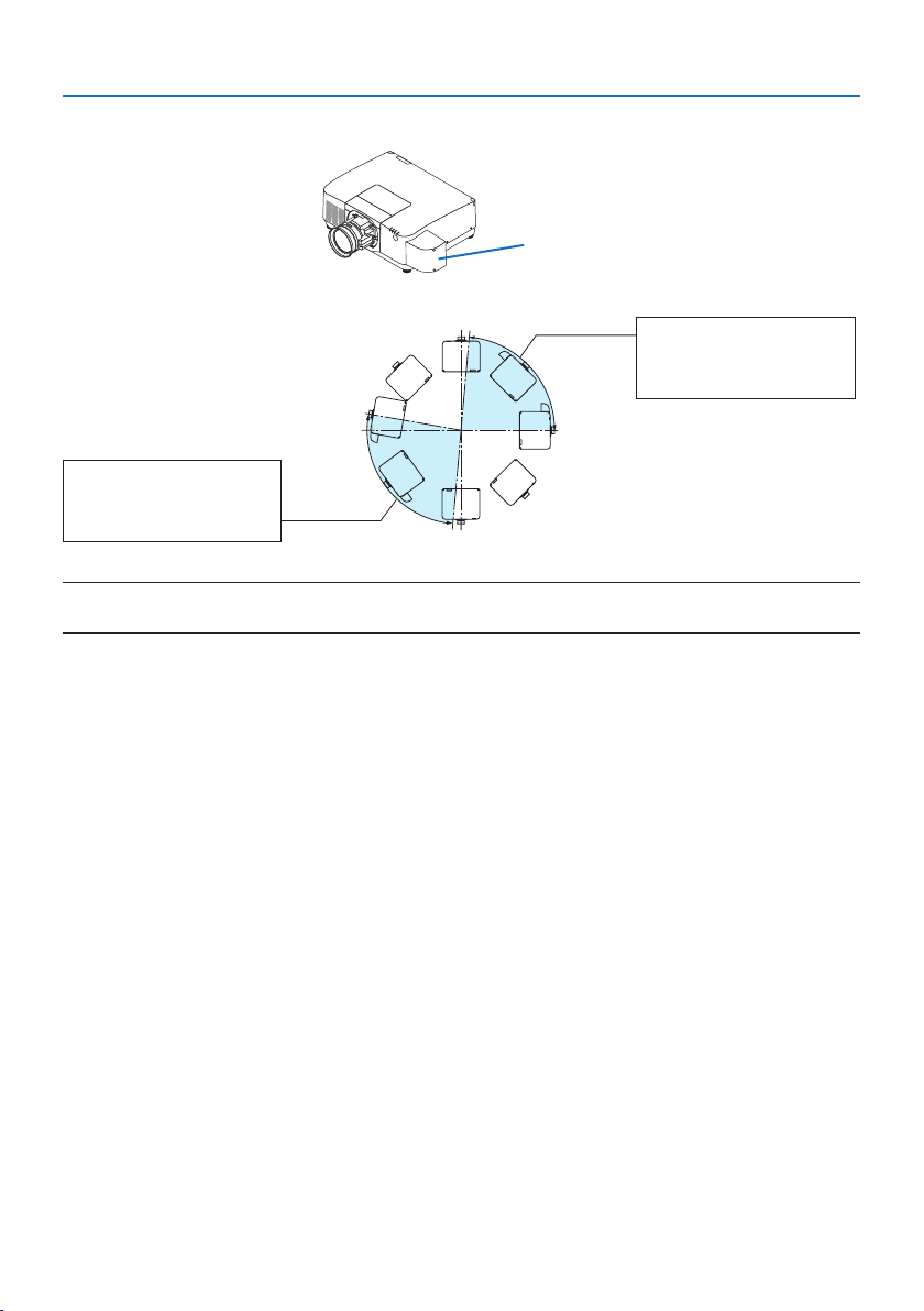
Precautions when installing the projector at an angle
This projector can be installed universally in every angle. When installing the projector at the angles
shown below, the separately sold option cover is required to be attached to the projector.
For tilted installation of the projector, use a metal tting with sucient strength to prevent it from
falling.
WARNING
• Using without the option cover violates safety regulations. Also, powering the projector on
without the option cover installed could result in a re.
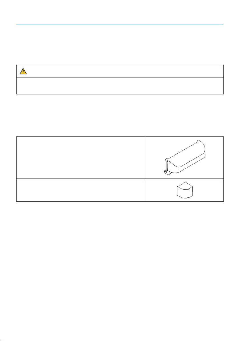
Model name of option cover
NP13CV-W for PA1705UL-W/PA1505UL-W
NP13CV-B for PA1705UL-B/PA1505UL-B
Two covers are packaged with the option cover NP13CV-W and NP13CV-B.
Option cover A: for attaching to the connection terminal
area
Option cover B: for attaching to the exhaust vent
Important Information
xxvii
The drawings below show the installation angle required to attach the option cover A and B re-
spectively.
• Both option cover A and B may need to be attached depending on the installation position of
the projector.
• Whether the option cover needs to be attached in the current installation position can be checked
on the [INFO.] screen of the on-screen menu.
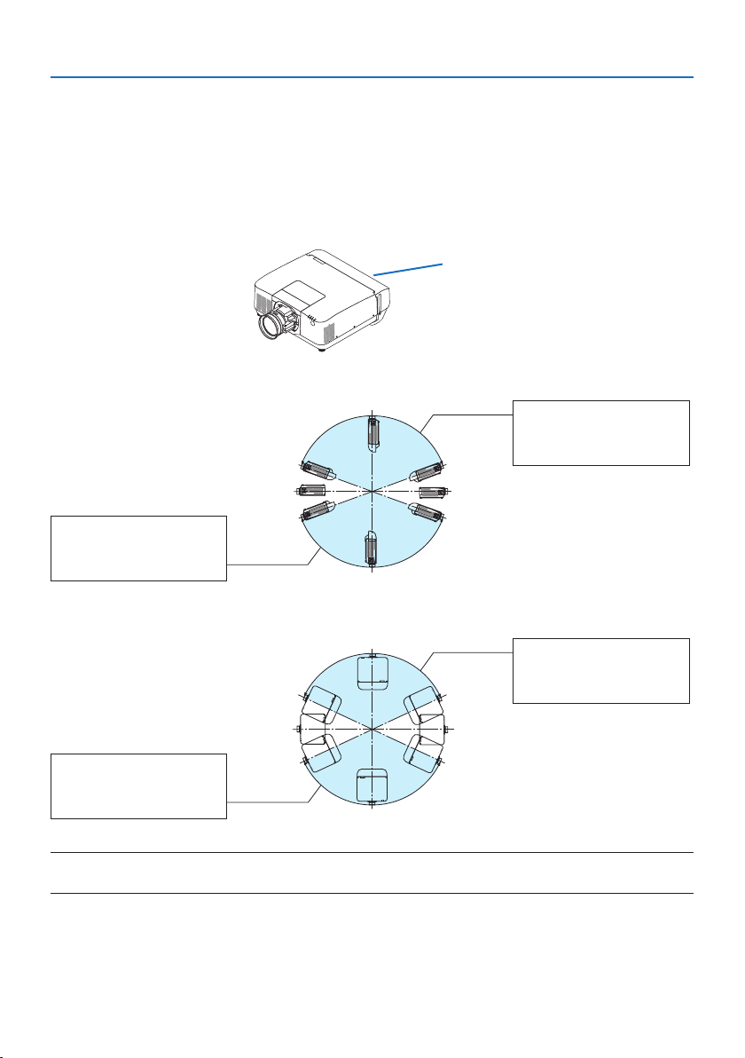
Installation angles required to attach the option cover A
Option cover A
In the direction of back and forth
20°–150°
Option cover A must be
attached
90°
270°
180° 0°
200°–330°
Option cover A must be
attached
In the direction of left and right
20°–160°
Option cover A must be
attached
90°
270°
180° 0°
200°–340°
Option cover A must be
attached
NOTE:
• The drawings show the image of installation angle as a reference. They are slightly dierent from the actual one.
Important Information
xxviii
Installation angles required to attach the option cover B
Option cover B
0°–85°
Option cover B must be
attached
90°
270°
180° 0°
170°–265°
Option cover B must be
attached
NOTE:
• The drawings show the image of installation angle as a reference. They are slightly dierent from the actual one.
Important Information
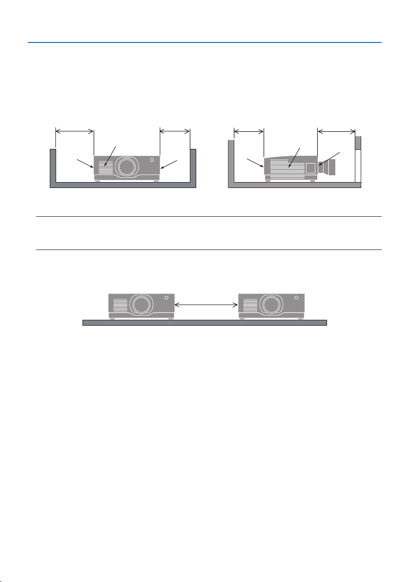
xxix
Clearance for Installing the Projector
• When installing the projector, keep sucient space around it, as described below. If not, the hot
exhaust emitted from the projector may be taken back in.
Also, make sure no wind from an air-conditioner hits the projector.
The projector’s heat control system may detect an abnormality (temperature error) and automati-
cally shut o the power.
dc
b
b
a
a
b
a
c
d
a: Intake vent / b: Exhaust vent / c: 20 cm/8" or greater / d: 30 cm/12" or greater
NOTE:
• In the above gure, it is assumed that there is sucient space above the projector.
• If the option cover is installed, leave a space of 20 cm/8" between the projector and the option cover.
• When using multiple projectors together for multi-screen projection, provide sucient space
around the projectors for air intake and exhaust. When the intake and exhaust vents are obstructed,
the temperature inside the projector will rise and this may result in a malfunction.
About Copyright of original projected pictures:
Please note that using this projector for the purpose of commercial gain or the attraction of public
attention in a venue such as a coee shop or hotel and employing compression or expansion of the
screen image with the following functions may raise concern about the infringement of copyrights
which are protected by copyright law.
[ASPECT RATIO], [KEYSTONE], Magnifying feature and other similar features.
[AUTO POWER OFF] Function
The factory default setting for [AUTO POWER OFF] is 15 minutes. If no input signal is received and no
operation is performed on the projector during 15 minutes, the projector is automatically powered
o for saving the power consumption. In order to control the projector by an external device, set
the [AUTO POWER OFF] to [OFF].

Important Information
xxx
Trademarks
• Cinema Quality Picture logo, ProAssist, and Virtual Remote are trademarks or registered trademarks
of Sharp NEC Display Solutions, Ltd. in Japan, in the United State and other countries.
• The terms HDMI, HDMI High-Denition Multimedia Interface, HDMI Trade dress and the HDMI
Logos are trademarks or registered trademarks of HDMI Licensing Administrator, Inc.
• HDBaseT™ and the HDBaseT Alliance logo are trademarks of the HDBaseT Alliance.
• Trademark PJLink is a trademark applied for trademark rights in Japan, the United States of America
and other countries and areas.
• Blu-ray is a trademark of Blu-ray Disc Association.
• CRESTRON and CRESTRON ROOMVIEW are trademarks or registered trademarks of Crestron
Electronics, Inc. in the United States and other countries.
• Extron and XTP are registered trademarks of RGB Systems, Inc. in the United States.
• Art-Net™ Designed by and Copyright Artistic Licence Holdings Ltd.
• Other product and company names mentioned in this user’s manual may be the trademarks or
registered trademarks of their respective holders.
• Virtual Remote Tool uses WinI2C/DDC library, © Nicomsoft Ltd.
1
1-1. Introduction to the Projector
This section introduces you to your new projector and describes the features and controls.
• Liquid crystal type high brightness/high resolution projector
This projector has a display resolution of 1920 dots × 1200 lines (WUXGA) and an aspect ratio
of 16:10.
Model Brightness
PA1705UL-W/PA1705UL-B 16000 lm (Center 17000 lm)
PA1505UL-W/PA1505UL-B 14000 lm (Center 15000 lm)
• A long-life laser diode is equipped in the light module
The laser light source has a long service life, so replacement, adjustment, and other maintenance
should not be necessary for an extended period of time.
• A proprietary sealed structure that achieves highly dust-proof performance
Due to its excellent dust-proof performance, the projector is not equipped with a lter. Filter
replacement is therefore unnecessary.
• Wide range of optional lenses selectable according to the place of installation
This projector supports 6 types of optional lenses, providing a selection of lenses adapted to a
variety of places of installation and projection methods.
Note that no lens is mounted upon shipment from the factory. Please purchase optional lenses
separately.
• 360 dgeree free projection
The projector is equipped with a “tilt-free” function for 360° projection vertically and a “roll-free”
function for 360° projection horizontally.
Note, however, that the separately sold option cover is required to be attached to the projector depending
on the installation angle of the projector.
• High quality pictures using Cinema Quality Picture technology
The projector displays extremely high quality pictures by combining the tech-
nology used to develop digital cinema projectors with the image processing
technologies we have amassed over our countless years of developing projectors.
• Multi-screen projection using multiple projectors
This projetor equips the HDBaseT IN and HDBaseT OUT ports. Using a LAN cable, control signals
can be transmitted in addition to the audio/visual signals (up to four devices can be connected).
The edge blending function creates smooth borders when using multiple units to project a
single image.
1. Check the product overview, supplied items and part names

1. Check the product overview, supplied items and part names
2
• Simultaneous display of 2 images (PIP/PICTURE BY PICTURE)
Two images can be projected simultaneously with a single projector.
There are two types of layouts for the two images: [PIP] in which a sub-picture is displayed on
the main picture, and [PICTURE BY PICTURE] in which the main and sub pictures are displayed
next to each other.
• Seamless switch function for smoother screen changes when switching the signal
When the input connector is switched, the image displayed before switching is held so that that
the new image can be switched to without a break due to absence of a signal.
• Supports wired LAN
Equips the LAN and HDBaseT ports. Utilizing a wired LAN connected with these ports, it enables
to control the projector by a computer.
• Convenient software applications
Compatible with our software applications (NaViSet Administrator 2, ProAssist, Virtual Remote
Tool, etc.). The projector can be controlled from a computer connected via a wired LAN.
• NaViSet Administrator 2
You can monitor the status of the projector and control a variety of functions.
• ProAssist
Necessary adjustments can be made smoothly for multi-screen projection.
• Virtual Remote Tool
A virtual remote control is displayed on the computer screen to perform simple controls
such as turning the projector on/o, switching signals, etc. It is also possible to change the
background logo of the projector.
Please visit our web site for downloading each software.
URL: https://www.sharp-nec-displays.com/dl/en/index.html
• CRESTRON ROOMVIEW and Extron XTP compatibility
The projector supports CRESTRON ROOMVIEW and Extron XTP, allowing multiple devices con-
nected in the network to be managed and controlled from a computer. Moreover, it enables to
output and control image via an Extron XTP transmitter connected with the projector.
• Energy-saving design with a standby power consumption of 0.15 W (100-130 V AC) / 0.20
W (200-240 V AC)
Selecting [ON] for [POWER-SAVING] from the menu can put the projector in power-saving mode.
When network is enabled: 0.4 W (100-130 V AC)/0.5 W (200-240 V AC)
When the network is disabled: 0.15 W (100-130 V AC)/0.20 W (200-240 V AC)

1. Check the product overview, supplied items and part names
3
• [LIGHT MODE] and “Carbon Meter” display
Three [LIGHT MODE] options can be selected according to the purpose of use. [LIGHT ADJUST]
can also be used to reduce output power and control energy consumption. The energy-saving
eect from that time will be factored into the amount of reduced CO
2
emissions and displayed
in the conrmation message when turning the power o as well as the [INFO.] area in the on-
screen menu (CARBON METER)
1. Check the product overview, supplied items and part names
4
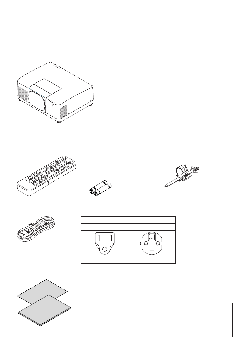
1-2. What’s in the Box?
Make sure your box contains everything listed. If any pieces are missing, contact your dealer.
Please save the original box and packing materials if you ever need to ship your projector.
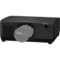
Projector
Dust cap for lens
(9NER0271)
* The projector is shipped without a lens.
Remote control
(7N901322)
AAA alkaline batteries (x2) Power cord stopper
(24C10881)
Plug type
For USA For EU
7N080534 7N080032
Power cord
• Important Infomation
(TINS-0015VW01)
• Quick Setup Guide
(TINS-0016VW01)
• Security Sticker
(Use this sticker when security password is set on.)
For USA and Canada only
Limited warranty
For customers in Europe
You will nd our current valid Guarantee Policy on our Web Site:
https://www.sharpnecdisplays.eu
1. Check the product overview, supplied items and part names
5
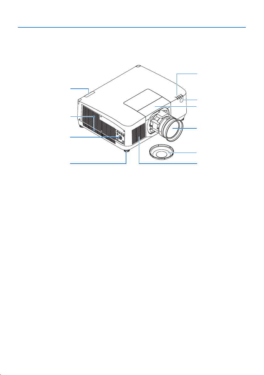
1-3. Part Names of the Projector
Front
The lens is sold separately. The description below is for when the NP54ZL lens is mounted.
1
2
3
8
6
5
4
7
6
9
1. Exhaust vent
Heated air is exhausted from here.
2. Controls
The projector’s power can be turned ON/
OFF, and the signal for the projected image
can be switched here.
3. Adjustable Tilt Foot
Rotate the tilt feet to adjust the left/right
orientation.
4. Intake vent
Takes in outside air to cool the unit.
5. Indicator Section
The indicator light turns on or blinks to
relay the status of the projector (Power ON/
Standby/etc.)
6. Remote Sensor
This part receives signals from the remote
control. There are two locations on the front
and back of the projector.
7. Lens
Images are projected from here. (Lens unit
sold separately.)
8. Lens Cap
(The optional lens is shipped with the lens
cap.)
9. Lens cover
Remove this when installing and removing
a lens unit.
1. Check the product overview, supplied items and part names
6
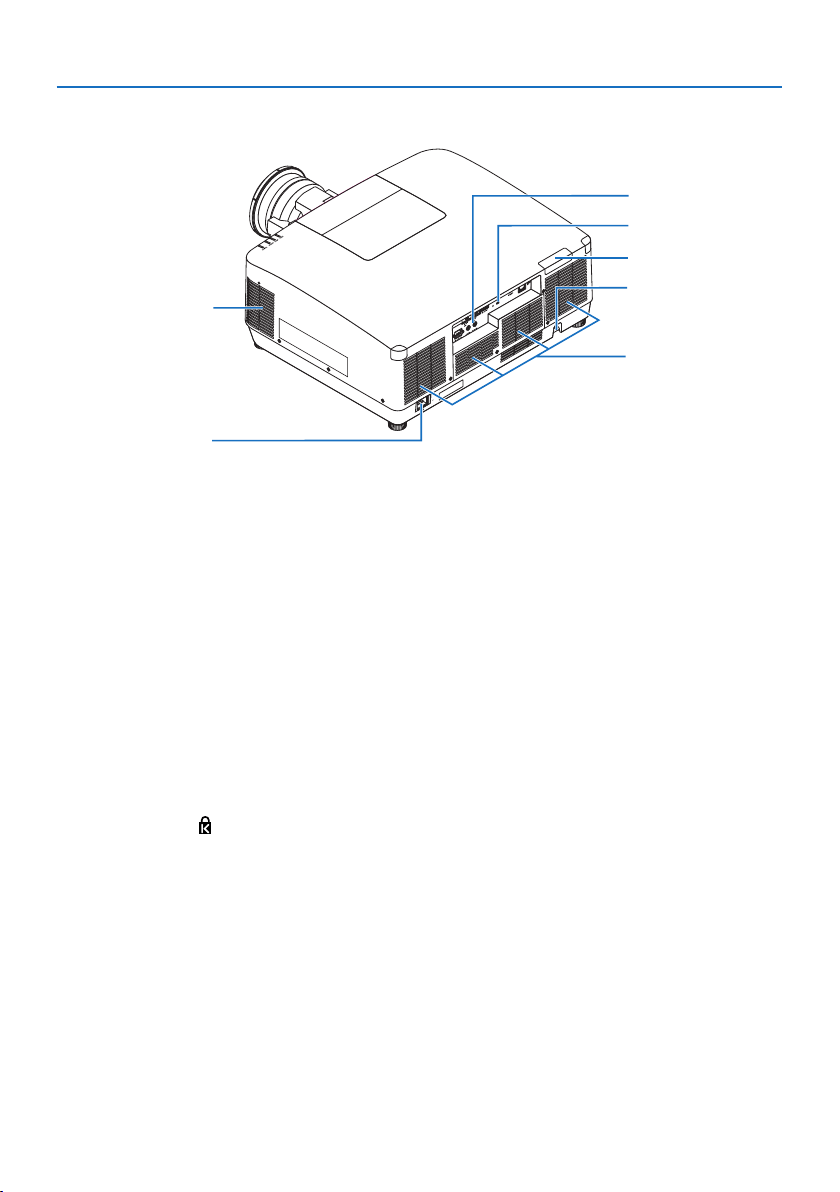
* Security and theft protection lock compatible with Kensington security cables/equipment. For products,
visit Kensington’s website.
Rear
1
7
2
3
4
6
5
1. Exhaust vent
Heated air is exhausted from here.
2. Intake vent
Takes in outside air to cool the unit.
3. Security Bar
Attach an anti-theft device. The security bar
accepts security wires or chains up to 0.18
inch/4.6 mm in diameter.
4. Remote Sensor
This part receives signals from the remote
control. There are two locations on the front
and back of the projector.
5. Security Slot ( )*
This is used when attaching an anti-theft
cable.
6. Terminals
Connect the cables for the various audio
and video signals.
7. AC IN Terminal
Connect the supplied power cord’s three-
pin plug here, and plug the other end into
an active wall outlet.
1. Check the product overview, supplied items and part names
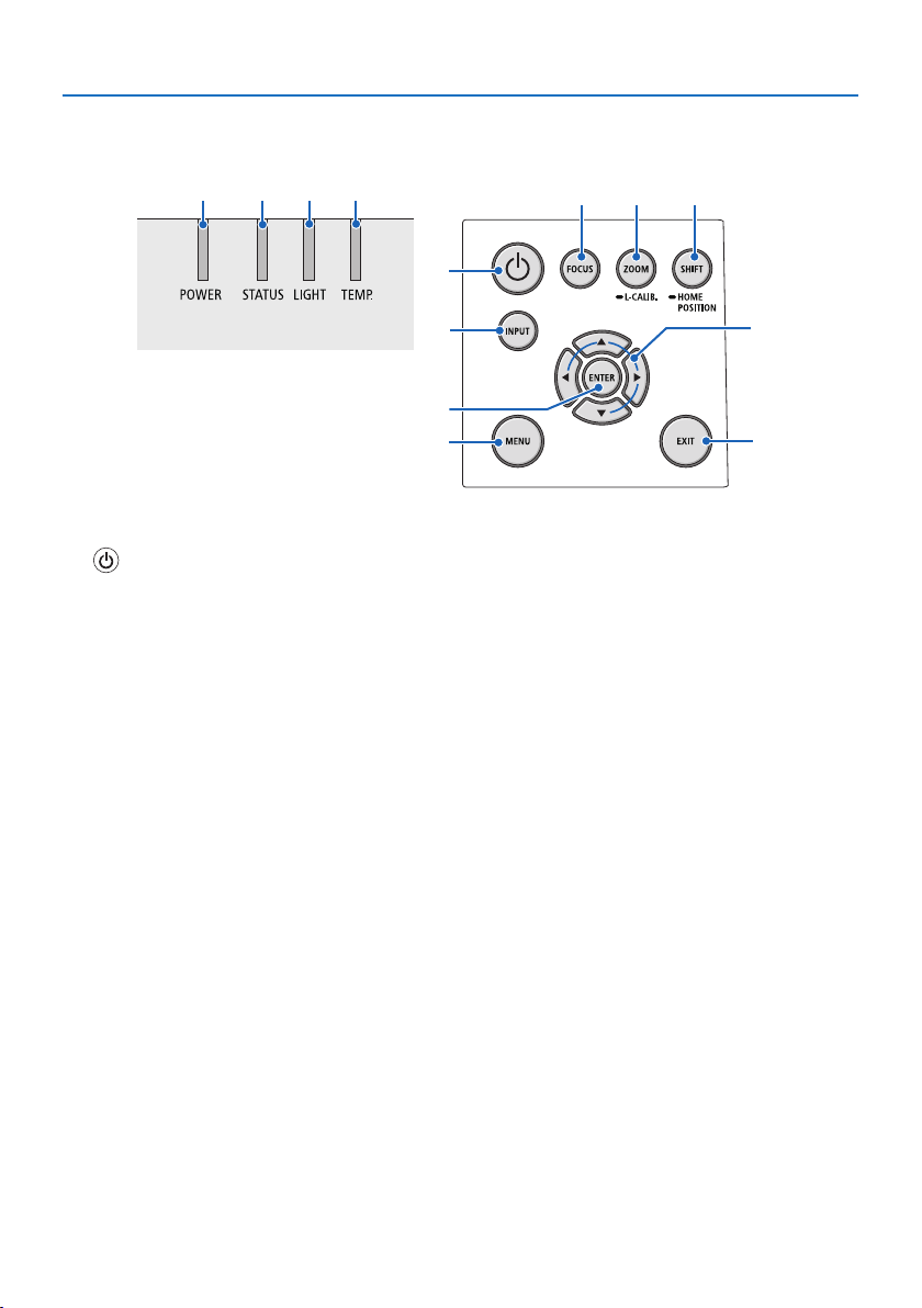
7
Controls/Indicators
2 3 4 5
10
7
8
1
6
9
11 12
13
1. (POWER) Button
Switches between projector’s power on and
standby.
When turning off the power (standby),
pressing the button once will bring up a
confirmation message on the screen, so
press the button one more time.
2. POWER Indicator
Indicates the projector’s power state. The
indicator lights up in blue when the power is
on. Depending on the state of power, it will
light up or blink in either green or orange
when power is o. Refer to the “Indicator
Message” section for details.
(→ page 40)
3. STATUS Indicator
This lights up or blinks when an operation
button is pressed while the unit is in key
lock mode, while the lens is calibrating, etc.
Refer to the “Indicator Message” section for
details.
(→ page 40)
4. LIGHT Indicator
Indicates the state of the light source.
5. TEMP. Indicator
Indicates high temperatures around the
projector.
6. INPUT Button
Selects the input signal. Pressing it quickly
will display the input selection screen. Press-
ing it for one second or longer will begin a
series of automatic checks in the order of
HDMI1 → HDMI2 → HDBaseT → SDI, and if
an input signal is detected then that signal
will be projected.
7. MENU Button
Displays the on-screen menu for various
settings and adjustments.
8. ▲▼◀▶ / Volume Buttons ◀▶
• When the on-screen menu is displayed,
use the ▼▲◀▶ buttons to select the item
that you wish to set or adjust.
• Changes the pattern when the test pat-
tern is displayed.
• When the on-screen menu is not dis-
played, use the ◀ / ▶ buttons to adjust
the sound output from the projector.
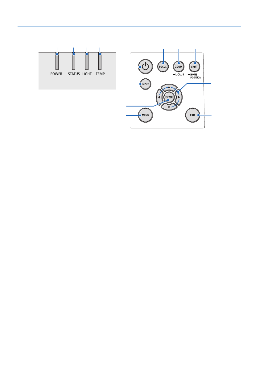
1. Check the product overview, supplied items and part names
8
9. ENTER Button
Moves to the next menu when the on-
screen menu is displayed. Confirms the
item when the confirmation message is
displayed.
10. EXIT Button
Returns to the menu on the previous
level when the on-screen menu is displayed.
Closes the menu when a cursor appears in
the main menu. Cancels the operation when
the conrmation message is displayed.
11. FOCUS Button
Open the focus adjustment screen and focus
the projected image.
12. ZOOM/L-CALIB. Button
• Short press to open the zoom adjust-
ment screen. Finely adjust the size of the
projected image.
• Long press (two seconds or longer) to cor-
rect the adjustment range of the attached
lens unit (calibration).
13. SHIFT/HOME POSITION Button
• Short press to display the lens shift screen.
Adjust them using the ▼▲◀▶ buttons.
• Long press (2 seconds or longer) to return
the lens shift adjustment to its initial posi-
tion.
2 3 4 5
10
7
8
1
6
9
11 12
13
1. Check the product overview, supplied items and part names
9
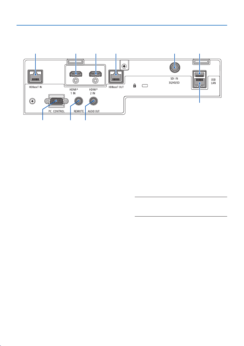
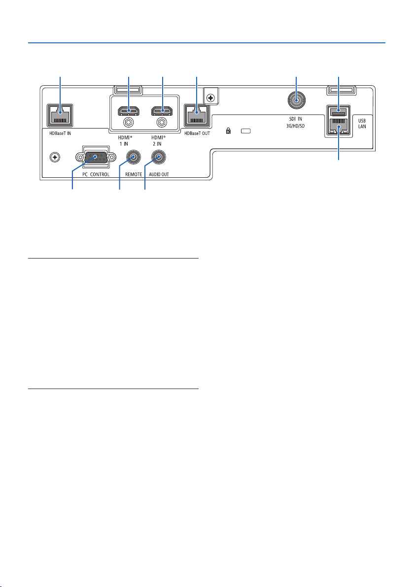
Terminal Panel Features
25
13
6910
8
4
7
1. HDMI 1 IN Terminal (Type A)
Connects to the output terminals of a com-
puter, blu-ray player, etc.
2. HDMI 2 IN Terminal (Type A)
Connects to the output terminals of a com-
puter, blu-ray player, etc.
3. SDI IN Terminal (BNC)
Connects to the SDI output terminal on the
video device.
4. HDBaseT IN Port (RJ-45)
Connects to a commercially available HD-
BaseT compatible transmission devices.
Also used when connecting multiple projec-
tors in daisy chaining.
5. HDBaseT OUT Port (RJ-45)
Outputs incoming signals from the HDMI
1 IN terminal, HDMI 2 IN terminal, and
HDBaseT IN Port.
6. AUDIO OUT Mini Jack (Stereo Mini)
Outputs the audio signal corresponding to
the image projected from the projector. The
output volume can be adjusted using the
◀ / ▶ buttons.
7. USB Port (Type A)
Connect a commercially available USB
mouse and use it to navigate the menu.
NOTE:
• Not guarantee the performance of all USB mouse avail-
able on the market.
8. LAN Port (RJ-45)
Connects the unit to a wired LAN.
9. PC CONTROL Port (D-Sub 9 Pin)
Use this port to connect a PC or control
system. This enables you to control the pro-
jector using serial communication protocol.
1. Check the product overview, supplied items and part names
10
25
13
6910
8
4
7
10. REMOTE Terminal (Stereo Mini)
Use this terminal for wired remote control
of the projector.
NOTE:
• When a remote control cable is connected to the REMOTE
terminal, infrared remote control operations cannot be
performed.
• When [HDBaseT] is selected in the [REMOTE SENSOR] and the
projector is connected to a commercially-available transmis-
sion device that supports HDBaseT, remote control operations
in infra-red cannot be carried out if transmission of remote
control signals has been set up in the transmission device.
However, remote control using infrared rays can be carried
out when the power supply of the transmission device is
switched o.

1. Check the product overview, supplied items and part names
11
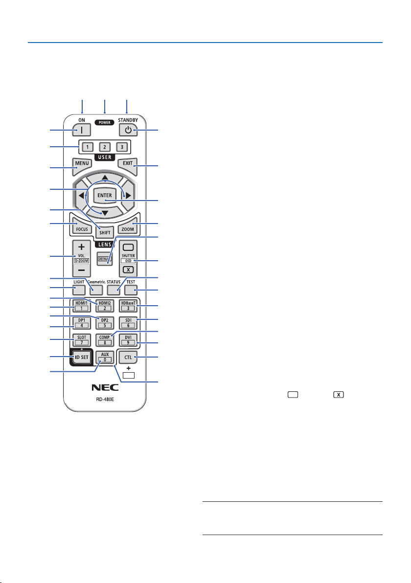
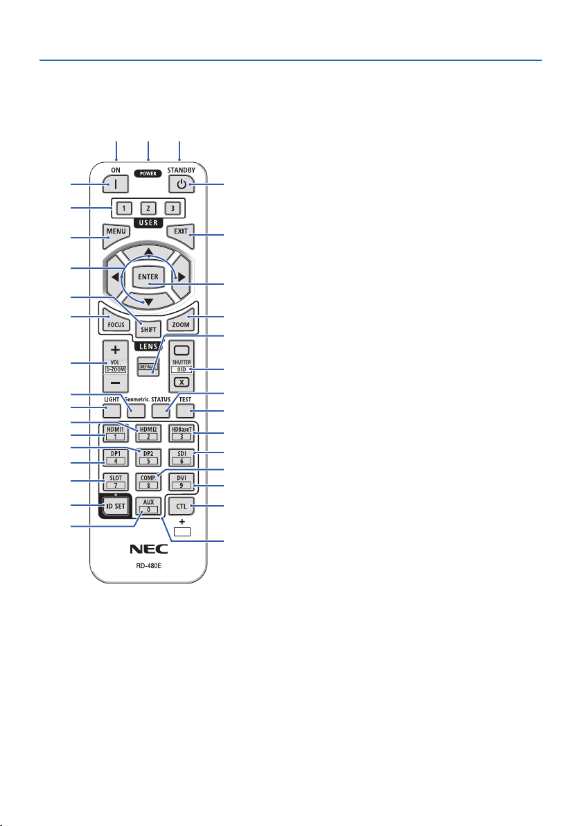
1-4. Part Names of the Remote Control
112
3
5
4
7
6
9
8
12
15
14
10
11
13
16
17
20
21
18
19
25
27
28
31
23
26
30
29
24
22
32
1. Infrared Transmitter
Remote control signals are sent via infrared signal.
Point the remote control at the remote control
receiver on the projector.
2. Remote Jack
Connect a commercially available remote cable
here for wired operation.
3. POWER ON Button ( )
Turns power ON when in sleep or standby mode.
4. POWER STANDBY Button ( )
Pressing the button once will display the shutdown
conrmation message. Press the POWER STANDBY
(or ENTER) button once more to power down the
projector.
5. USER 1/2/3 Button
The following 14 functions can be selected and set.
When the character input screen is displayed, use
this to switch the character keyboard, insert a
space, and erase characters.
6. MENU Button
Displays the on-screen menu for various settings
and adjustments.
7. EXIT Button
Returns to the menu on the previous level when
the on-screen menu is displayed. Closes the menu
when a cursor appears in the main menu. Cancels
the operation when the conrmation message is
displayed.
8. ▲▼◀▶ Button
• When the on-screen menu is displayed, use the
▼▲◀▶ buttons to select the item that you wish
to set or adjust.
• Changes the pattern when the test pattern is
displayed.
1. Check the product overview, supplied items and part names
12
9. ENTER Button
Moves to the next menu when the on-screen menu
is displayed. Conrms the item when the conrma-
tion message is displayed.
10. FOCUS Button
Opens the focus adjustment screen. Adjust the
focus (of the lens) with the ◀ / ▶ buttons.
11. SHIFT Button
The lens shift adjustment screen will be displayed.
Use the ▼▲◀▶ buttons to adjust the lens position.
12. ZOOM Button
Opens the zoom adjustment screen. Adjust zoom
with the ◀ / ▶ buttons.
13. VOL./D-ZOOM (+)(−) Button
Adjusts the volume level of the audio output termi-
nals. Simultaneously pressing the CTL button will
expand or shrink the image (return to the original
state).
14. DEFAULT Button
Simultaneously pressing the CTL button when the
on-screen menu is displayed will reset the adjust-
ment values.
This only works for the items with DEFAULT dis-
played in the Operation Guide.
15. SHUTTER/OSD OPEN ( )/CLOSE ( ) Button
Press the CLOSE button to turn o the light source
and temporarily stop projection. Press the OPEN
button to resume. Simultaneously press the CTL
and CLOSE buttons to close the on-screen display
(On-Screen Mute). Simultaneously press the CTL
and OPEN buttons to go back.
16. LIGHT Button
Displays the light mode screen.
NOTE:
• The settings in [ADJUST] → [PICTURE] → [MODE] change the
screen displayed.
112
3
5
4
7
6
9
8
12
15
14
10
11
13
16
17
20
21
18
19
25
27
28
31
23
26
30
29
24
22
32

1. Check the product overview, supplied items and part names
13
17. Geometric. Button
Displays [GEOMETRIC CORRECTION] from the
on-screen menu. Use it to adjust distortions in
projected images.
18. STATUS Button
Displays [USAGE TIME] of [INFO.] from the on-
screen menu.
19. TEST Button
Projects a test pattern.
20. HDMI1 Button
Selects the HDMI1 input.
21. HDMI2 Button
Selects the HDMI2 input.
22. HDBaseT Button
Selects the HDBaseT input.
23. DP1 Button
(Not available on this series of projectors.)
24. DP2 Button
(Not available on this series of projectors.)
25. SDI Button
Selects the SDI input.
26. SLOT Button
(Not available on this series of projectors.)
27. COMP. Button
(Not available on this series of projectors.)
28. DVI Button
(Not available on this series of projectors.)
29. AUX Button
(Not available on this series of projectors. For future
expansion)
112
3
5
4
7
6
9
8
12
15
14
10
11
13
16
17
20
21
18
19
25
27
28
31
23
26
30
29
24
22
32
1. Check the product overview, supplied items and part names
14
30. ID SET Button
Used to set the control ID when performing indi-
vidual operations on multiple projectors using the
remote control. Also used to toggle the character
keyboard when the character input screen is dis-
played.
31. Numeric Keypad Button
Used to input the control ID when performing
individual operations on multiple projectors using
the remote control (set the control ID). Pressing
the 0 button while holding down the ID SET but-
ton will remove any control ID settings. Used to
enter alphanumeric characters directly when the
character input screen is displayed.
32. CTL Button
This is a multipurpose button for combined use
with other buttons.
112
3
5
4
7
6
9
8
12
15
14
10
11
13
16
17
20
21
18
19
25
27
28
31
23
26
30
29
24
22
32
1. Check the product overview, supplied items and part names
15
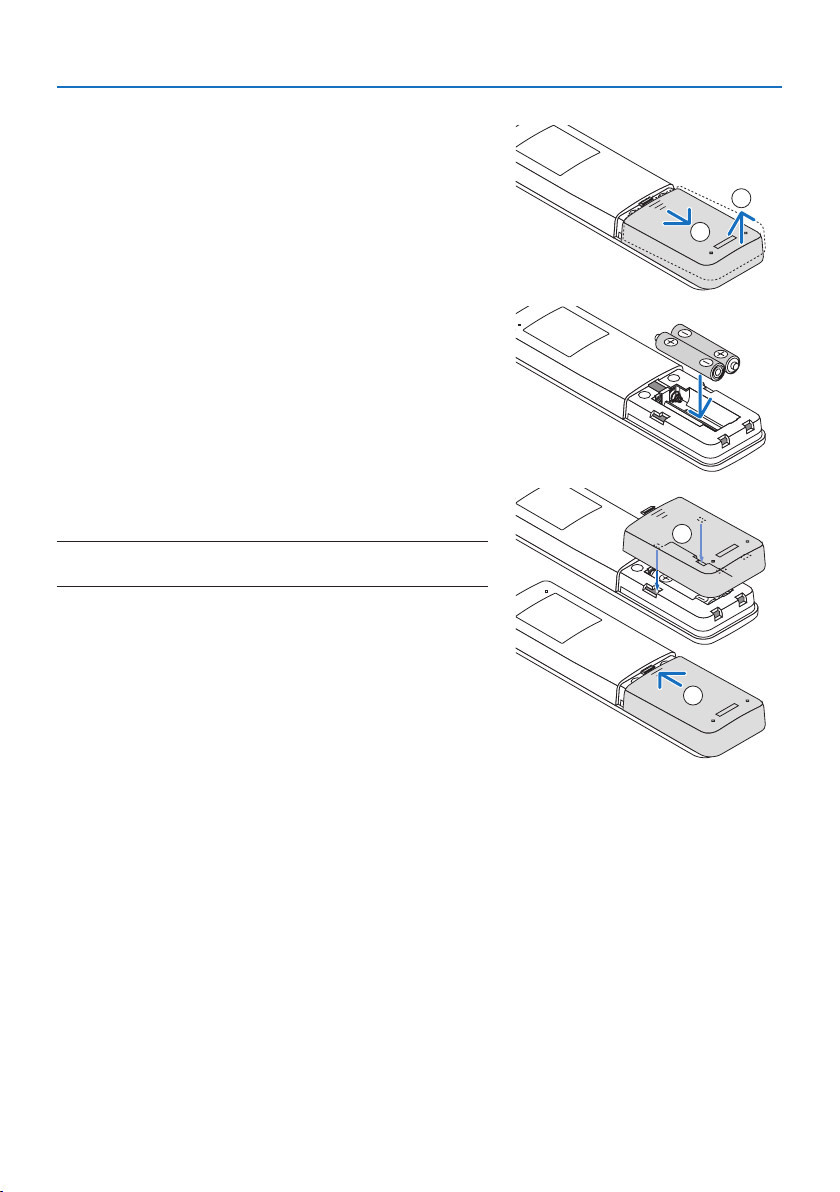
Battery Installation
1. Press the catch and remove the battery cover.
1
2
2. Install new ones (AAA). Ensure that you have the
batteries’ polarity (+/−) aligned correctly.
3. Slip the cover back over the batteries until it snaps
into place.
NOTE:
• Do not mix dierent types of batteries or new and old batteries.
1
2
Remote Control Precautions
• Handle the remote control carefully.
• If the remote control gets wet, wipe it dry immediately.
• Avoid excessive heat and humidity.
• Do not short, heat, or take apart batteries.
• Do not throw batteries into re.
• If you will not be using the remote control for a long time, remove the batteries.
• Ensure that you have the batteries’ polarity (+/−) aligned correctly.
• Do not use new and old batteries together, or use dierent types of batteries together.
• Dispose of used batteries according to your local regulations.
• Please note that if multiple projectors are installed nearby, other projectors may unintentionally
light up when you turn on the power using the remote control.
1. Check the product overview, supplied items and part names
16
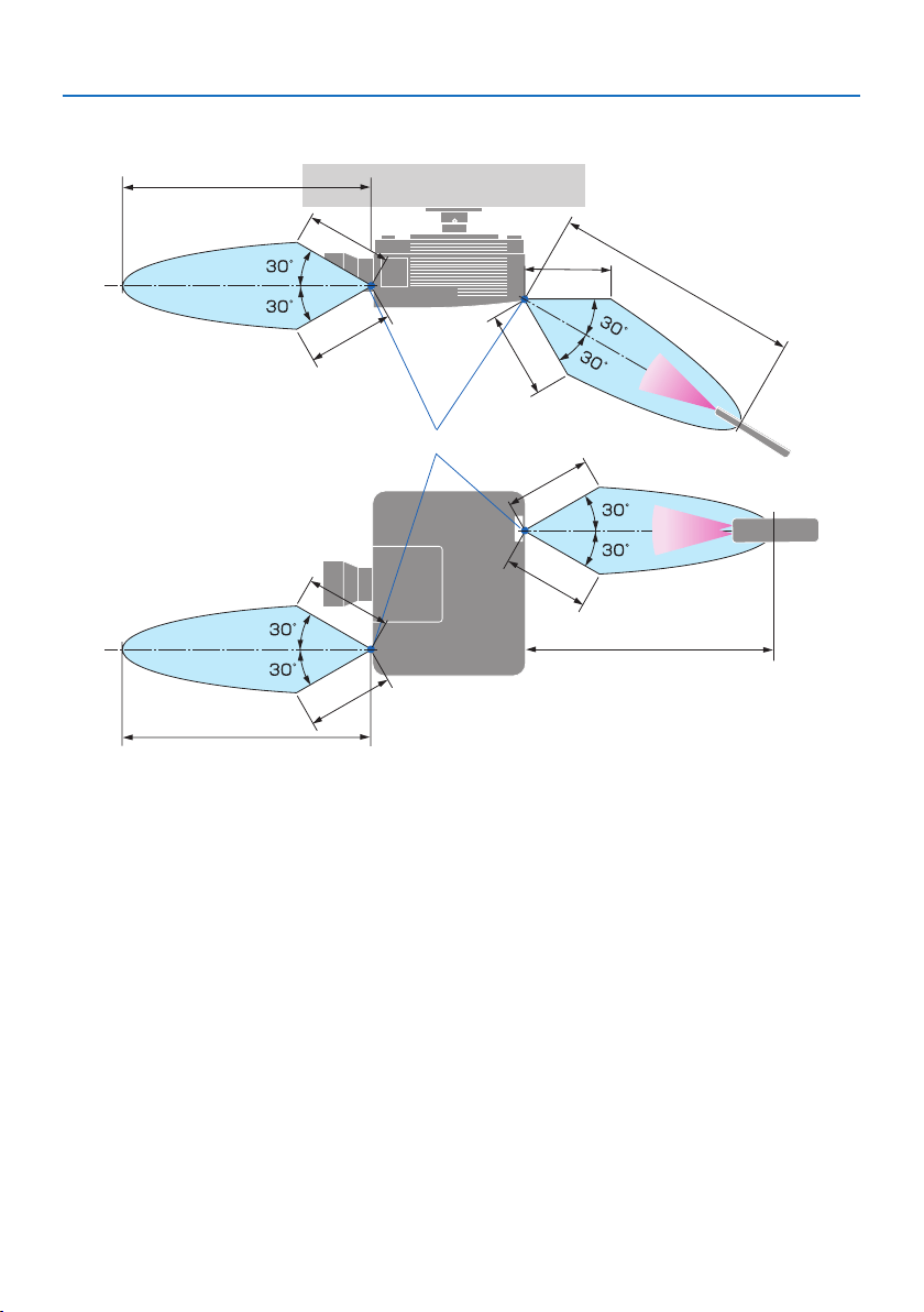
Operating Range for Wireless Remote Control
a
a
a
a
a
a
a
a
b
c
d
d
b
b
b
a: 7 m/276" / b: 20 m/787" / c: Remote sensor on projector cabinet / d: Remote control
• The projector will not respond if there are objects between the remote control and the sensor,
or if strong light falls on the sensor. Weak batteries will also prevent the remote control from
properly operating the projector.
1. Check the product overview, supplied items and part names
17
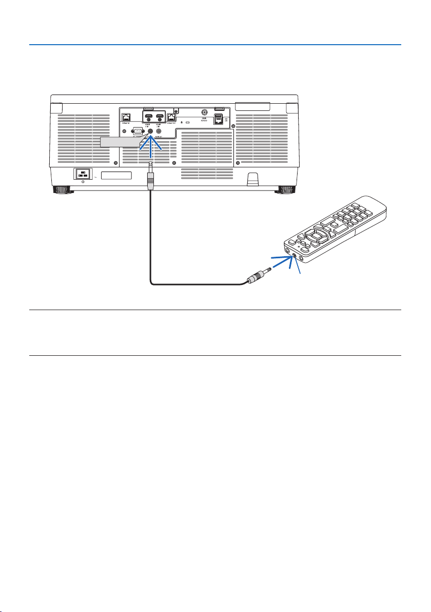
Using the Remote Control in Wired Operation
Connect one end of the remote cable to the REMOTE terminal and the other end to the remote
jack on the remote control.
REMOTE
a
a: Remote jack
NOTE:
• When a remote cable is inserted into the REMOTE terminal, the remote control does not work for infrared wireless communication.
• Power will not be supplied to the remote control by the projector via the REMOTE jack. Battery is needed when the remote control
is used in wired operation.

18
This section describes how to turn on the projector and to project a picture onto the screen.
2-1. Flow of Projecting an Image
Step 1
• Connecting your computer / Connecting the power cord (→ page 19)
Step 2
• Turning on the projector (→ page 22)
Step 3
• Selecting a source (→ page 25)
Step 4
• Adjusting the picture size and position (→ page 27)
Step 5
• Adjusting a picture and sound (→ page 34)
Step 6
• Making a presentation
Step 7
• Turning o the projector (→ page 35)
Step 8
• After use (→ page 36)
2. Projecting an Image (Basic Operation)

2. Projecting an Image (Basic Operation)
19
2-2. Connecting Your Computer/Connecting the Power Cord
1. Connect your computer to the projector.
This section will show you a basic connection to a computer.
Connect a commercially available HDMI cable between the computer's HDMI output connector
and the projector's HDMI 1 IN or HDMI 2 IN connector.
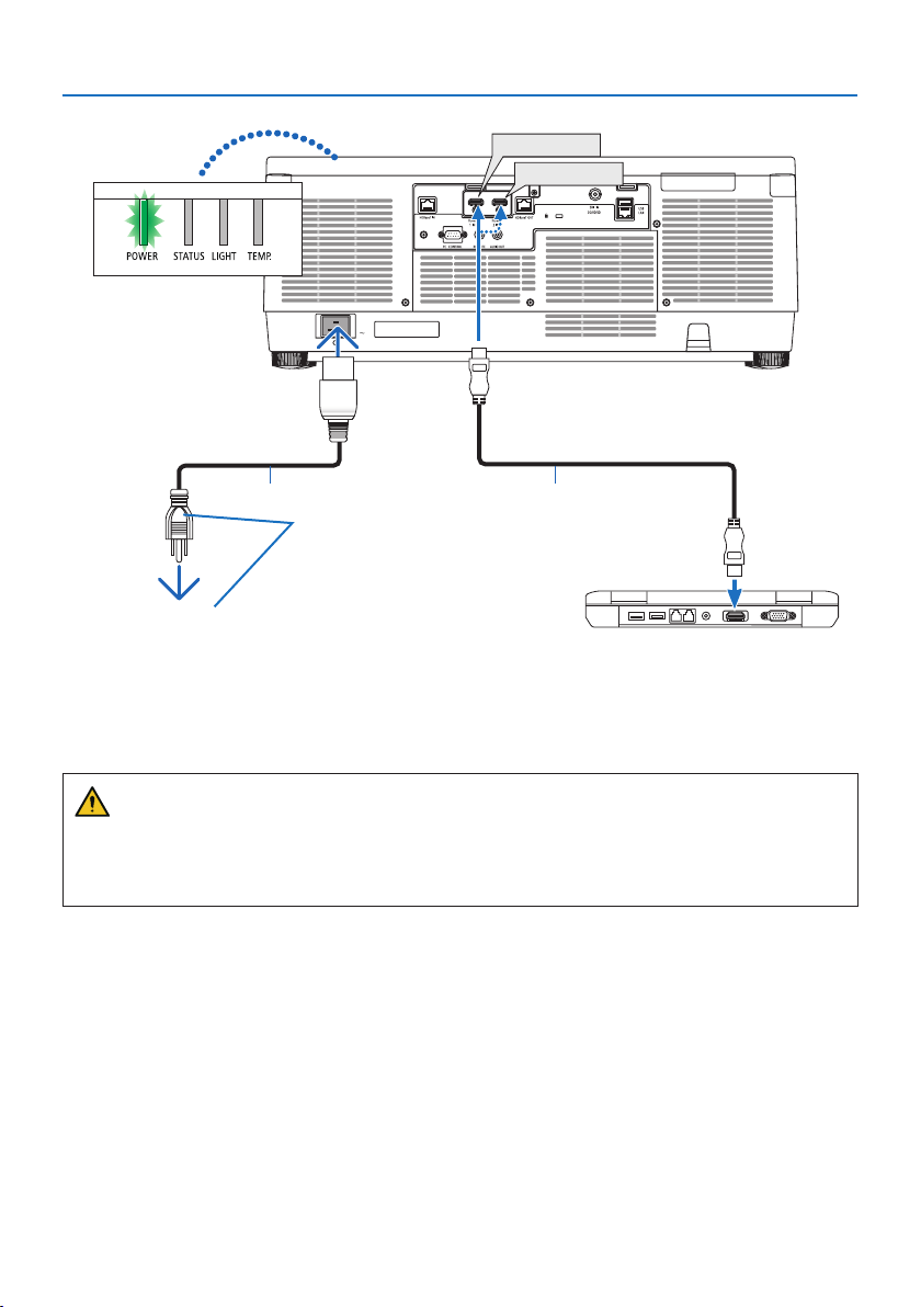
2. Connect the supplied power cord to the projector.
First connect the supplied power cord’s three-pin plug to the AC IN terminal of the projector,
and then connect another plug of the supplied power cord directly in the wall outlet. Do not
use any plug converter.
CAUTION:
• This equipment is designed to be used in the condition of the power cord connected to
earth. If the power cord is not connected to the earth, it may cause electric shock. Please
make sure the power cord is connected to the wall outlet directly and earthed properly.
Do not use a 2-core plug converter adapter.
• Be sure to connect the projector and the computer (signal source) to the same earth point.
If the projector and the computer (signal source) will be connected to dierent earth
points, uctuations in the earth potential may cause re or smoke.
• To prevent the power cord from coming loose, make sure that all the prongs of the power
cord plug are fully inserted into the AC IN terminal of the projector before using the power
cord stopper. A loose contact of the power cord may cause a re or electric shock.
Upon connecting the power cable, the POWER indicator of the projector will light.
2. Projecting an Image (Basic Operation)
20
a
b
HDMI 2 IN
HDMI 1 IN
Make sure that the prongs are fully inserted
into both the AC IN and the wall outlet.
To wall outlet
a: Power cord (supplied) / b: HDMI cable (not supplied)
• Use a Premium High Speed HDMI Cable.
CAUTION:
Parts of the projector may become temporarily heated if the projector is turned o with the
POWER button or if the AC power supply is disconnected during normal projector operation.
Use caution when picking up the projector.
2. Projecting an Image (Basic Operation)
21
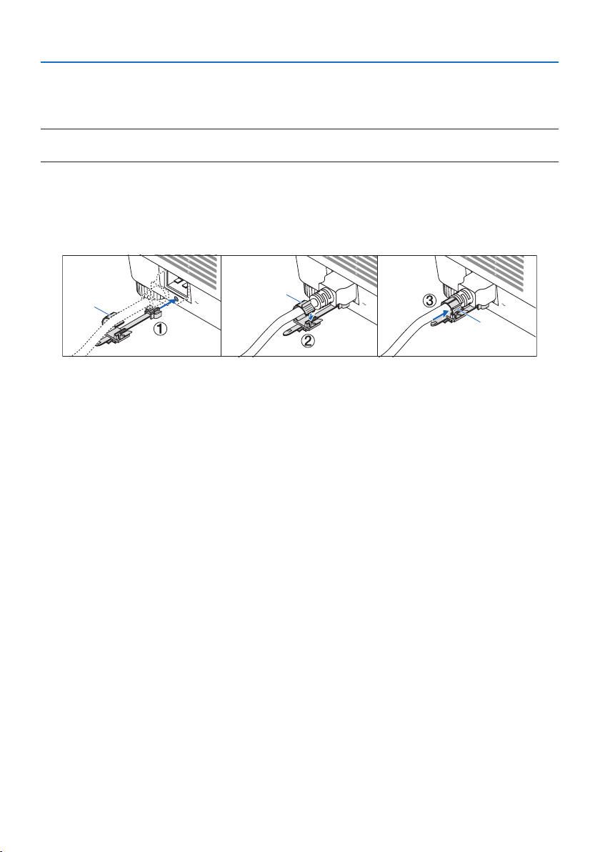
Using the power cord stopper
To prevent the power cord from accidently removing from the AC IN of the projector, use the power
cord stopper.
NOTE:
• If you pull on the power supply cord while the connector is xed, the main unit may fall down and be damaged
① With the clamper facing the power supply cord, align the tip of the power supply cord stopper
with the hole below the AC IN terminal and push it in.
②
Pass the power supply cord through the clamper and press the clamper to x it.
③ Slide the clamper until the base of the power plug.
a
a
a
a: Clamper
2. Projecting an Image (Basic Operation)
22
2-3. Turning on the Projector
WARNING
The projector produces a strong light. When turning on the power, operate from the side or rear
of the projector (outside the hazard zone). Also, when turning on the power, make sure no one
within the projection range is looking at the lens.
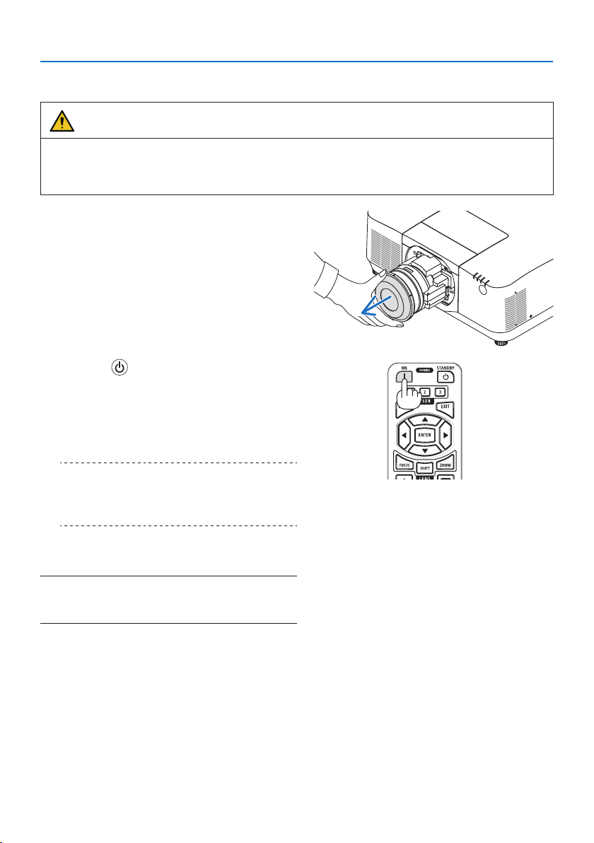
1. Remove the lens cap.
2. Press the (POWER) button on the projec-
tor cabinet or the POWER ON button on the
remote control.
The POWER indicator lit in green will start
to blink in blue. After that, the image will be
projected onto the screen.
TIP:
• When the message “PROJECTOR IS LOCKED! ENTER YOUR
PASSWORD.” is displayed, it means that the [SECURITY]
feature is turned on.
After you turn on your projector, ensure that
the computer or video source is turned on.
NOTE:
• A blue screen (blue background) is displayed when no signal is
being input (by factory default menu settings).
2. Projecting an Image (Basic Operation)
23
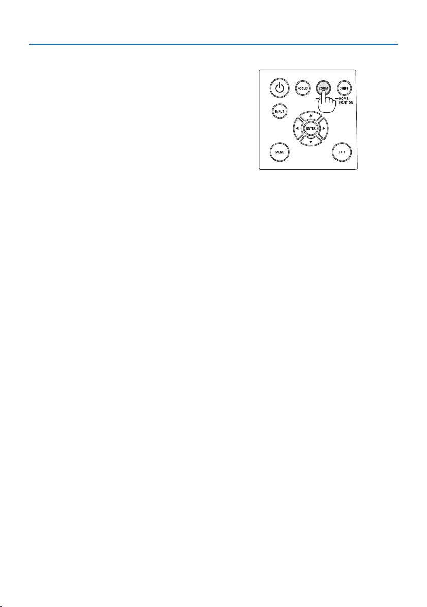
Performing Lens Calibration
After mounting the separately available lens unit or
replacing a lens unit, perform [LENS CALIBRATION]
by holding to press ZOOM/L-CALIB. button on the
cabinet over two seconds.
Calibration corrects the adjustable zoom, shift, and
focus range. If calibration is not performed, you may
not be able to get the best focus and zoom even if
you adjust the focus and zoom for the lens.
2. Projecting an Image (Basic Operation)
24
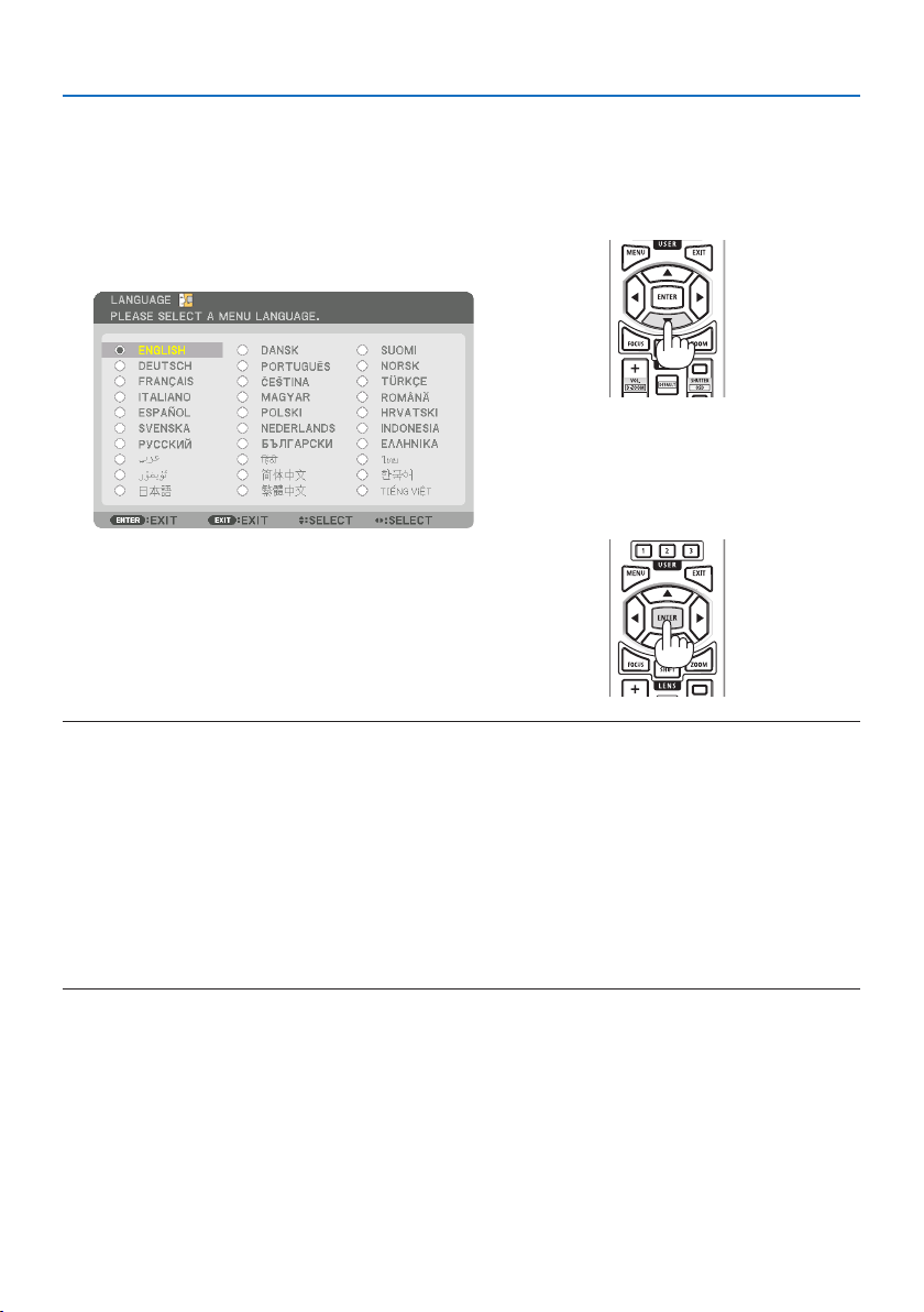
Note on Startup screen (Menu Language Select screen)
When you rst turn on the projector, you will get the Startup menu. This menu gives you the op-
portunity to select one of the 30 menu languages.
To select a menu language, follow these steps:
1. Use the ▲, ▼, ◀ or ▶ button to select one of
the 30 languages from the menu.
2. Press the ENTER button to execute the selec-
tion.
After this has been done, you can proceed to
the menu operation.
If you want, you can select the menu language
later.
NOTE:
• If the message, [PLEASE SET "DATE AND TIME".] is shown, please set the current date and time.
In the case this message is not shown, the [DATE AND TIME SETTINGS] is recommended to complete.
• Keep the lens cap o the lens while the projector’s power is on.
If the lens cap is on, it could be warped due to high temperature.
• If the STATUS indicator lights orange with the power button pressed, the projector will not be turned on since the [CONTROL PANEL
LOCK] has been [ON]. Cancel the lock by turning it o.
• While the POWER indicator is blinking blue in short cycles, the power cannot be turned o by using the power button.
• If the projector is kept in sleep mode or other similar state, the temperature of the internal components could rise even when the
projector is being used within its normal operating temperate. If the power is turned on in that state, the cooling fan will turn on
and the image will be projected after a short while.
2. Projecting an Image (Basic Operation)
25
2-4. Selecting a Source
Selecting the computer or video source
NOTE:
• Turn on the computer or video source equipment connected to the projector.
Detecting the Signal Automatically
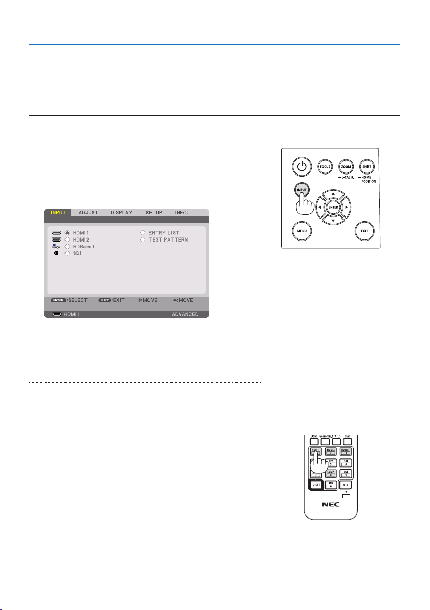
Press the INPUT button for 1 second or longer. The projector
will search for the available input source and display it. The
input source will change as follows:
HDMI1 → HDMI2 → HDBaseT → SDI → HDMI1 → …
• Press it briey to display the [INPUT] screen.
• Press the ▼/▲ buttons to match the target input terminal
and then press the ENTER button to switch the input. To
delete the menu display in the [INPUT] screen, press the
MENU or EXIT button.
TIP:
• If no input signal is present, the input will be skipped.
Using the Remote Control
Press any one of the HDMI1, HDMI2, HDBaseT, or SDI button.
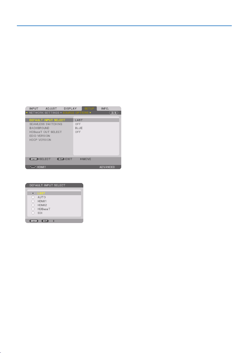
2. Projecting an Image (Basic Operation)
26
Selecting Default Source
You can set a source as the default source so that it will be displayed each time the projector is
turned on.
1. Press the MENU button.
The menu will be displayed.
2. Press the ▶ button to select [SETUP] and press the ▼ button or the ENTER button to select
[MENU(1)].
3. Press the ▶ button to select [SOURCE OPTIONS] and press the ▼ button or the ENTER
button.
4. Select [DEFAULT INPUT SELECT] and press the ENTER button.
The [DEFAULT INPUT SELECT] screen will be displayed.
5. Select a source as the default source, and press the ENTER button.
6. Press the EXIT button a few times to close the menu.
7. Restart the projector.
The source you selected in step 5 will be projected.
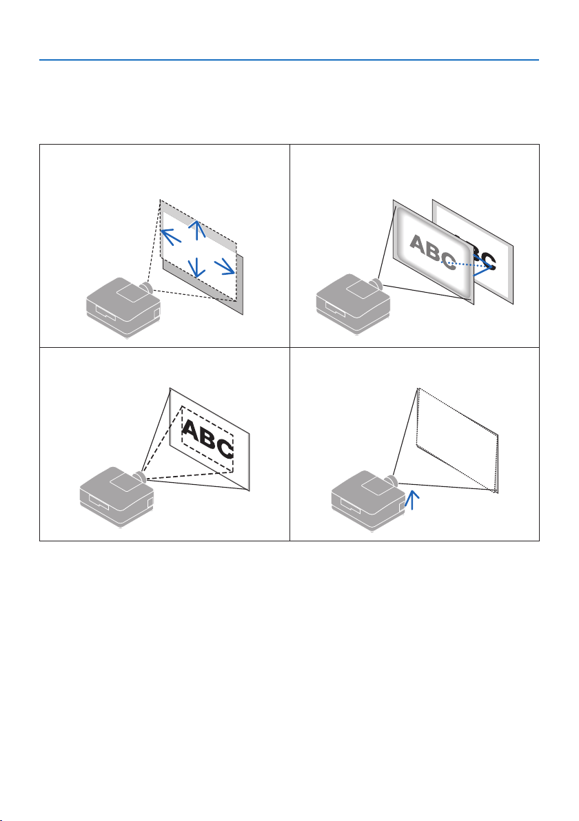
2. Projecting an Image (Basic Operation)
27
2-5. Adjusting the Picture Size and Position
Use the lens shift, the adjustable tilt foot, the zoom and the focus to adjust the picture size and
position.
In this chapter drawings and cables are omitted for clarity.
Adjusting the projected image’s vertical and
horizontal position
“Lens shift” (→ page 28)
Adjusting the focus
“Focus” (→ page 30)
Finely adjusting the size of an image
“Zoom” (→ page 32)
Adjusting the projected image’s inclination
“Tilt foot” (→ page 33)
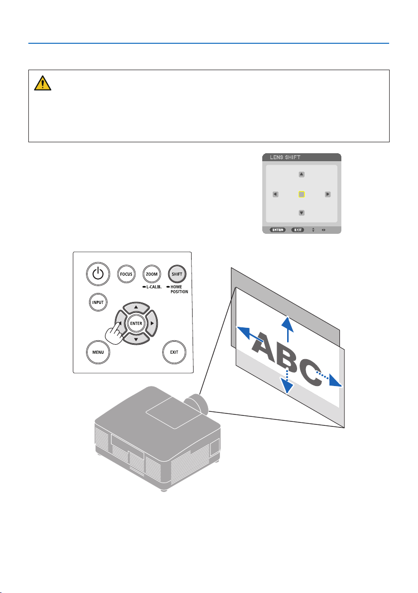
2. Projecting an Image (Basic Operation)
28
Adjusting the vertical position of a projected image (Lens shift)
CAUTION
• Perform the adjustment from behind or from the side of the projector. If adjustments are
performed from the front, your eyes could be exposed to strong light and get injured.
• Keep hands away from the lens mounting portion while performing a lens shift. Failure to do
so could result in ngers being pinched by the moving lens.
1. Press either SHIFT/HOME POSITION button
on the cabinet or SHIFT button on the remote
control.
The [LENS SHIFT] screen will be displayed.
2. Press the ▼▲◀▶ buttons to move the projected image.
To set back the lens to the home position
Press and hold the SHIFT/HOME POSITION button over 2 seconds. The lens mounted on the projec-
tor goes back to the home position. (roughly to the center position)
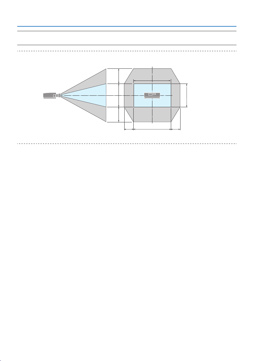
2. Projecting an Image (Basic Operation)
29
NOTE:
• If the lens is shifted to the maximum in the diagonal direction, the screen peripheral area will be dark or shaded.
TIP:
• The gure below shows the lens shift adjustment range (projection method: Desktop/Front) of the NP54ZL lens unit.
H
V
100 %V
65 %V
65 %V
100 %H
25 %H 25 %H
Description of symbols: V indicates vertical (height of the projected image), H indicates horizontal (width of the projected image).
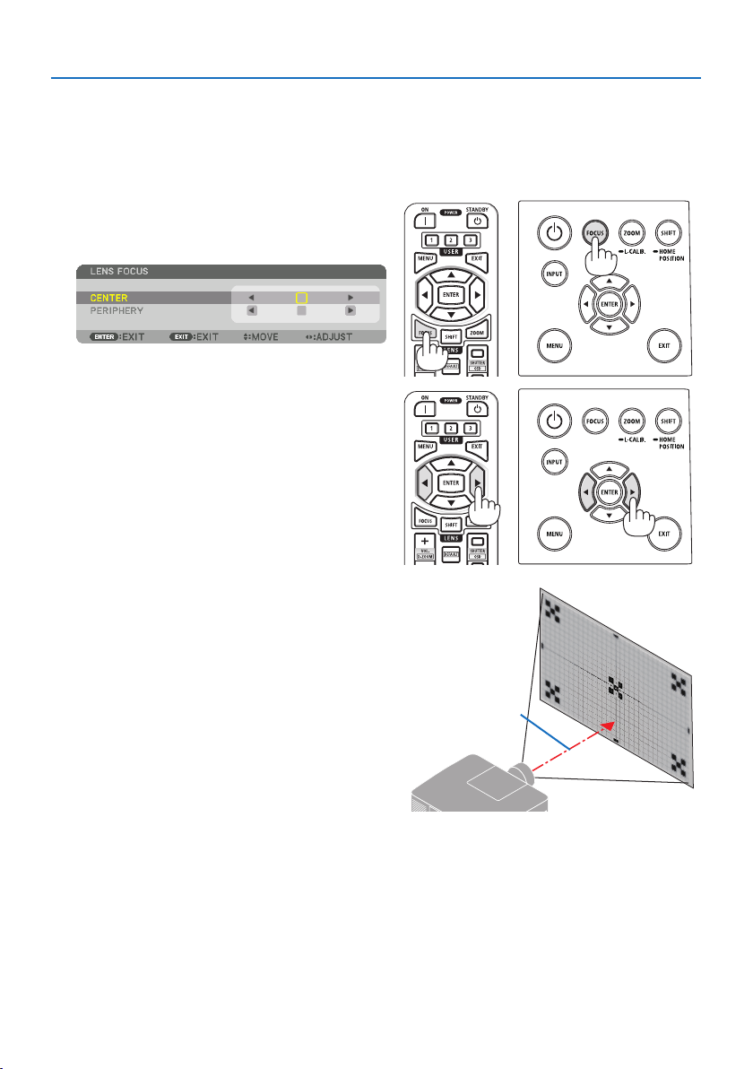
2. Projecting an Image (Basic Operation)
30
Focus
Recommend to perform the focus adjustment after leaving the projector under the state the TEST
PATTERN has been projected for over 30 minutes.
Applicable lens: NP51ZL/NP52ZL/NP53ZL
1. Press the FOCUS button.
The [LENS FOCUS] control screen will be dis-
played on.
Press ◀▶ buttons to adjust focus.
2. When the cursor is on the [CENTER] on on-
screen menu, press either ◀ or ▶ button to
align focus around the optical axis.
* The picture shows and example when the
lens shift is moved upward. Adjust the lens
until the bottom edge of the projection
screen is in focus.
Optical axis
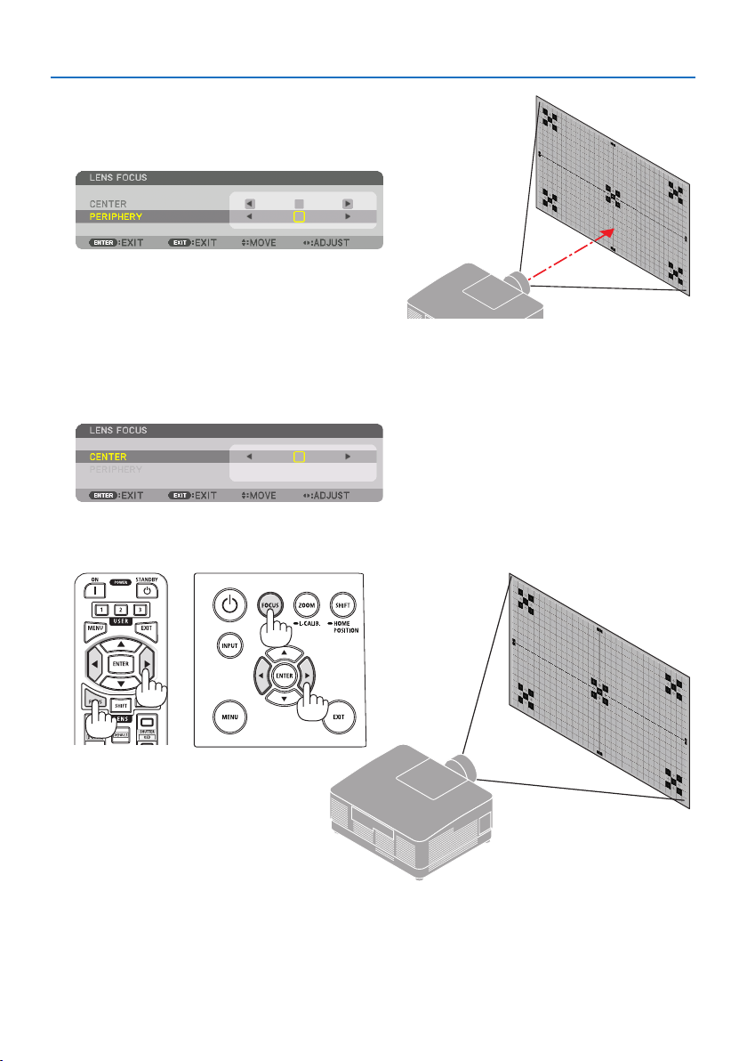
2. Projecting an Image (Basic Operation)
31
3. Press ▼ button to select the [PERIPHERY] on
the on-screen menu, and then press either
◀ or ▶ button to align the focus of screen
peripheral area.
4. Repeat steps 2 and 3 until the entire projec-
tion screen is in focus.
Applicable lens: NP54ZL/NP55ZL/NP56ZL
1. Press the FOCUS button.
The [LENS FOCUS] control screen will be displayed on.
Press ◀▶ buttons to adjust focus.
* [PERIPHERY] LENS FOCUS is not available for this lens unit.
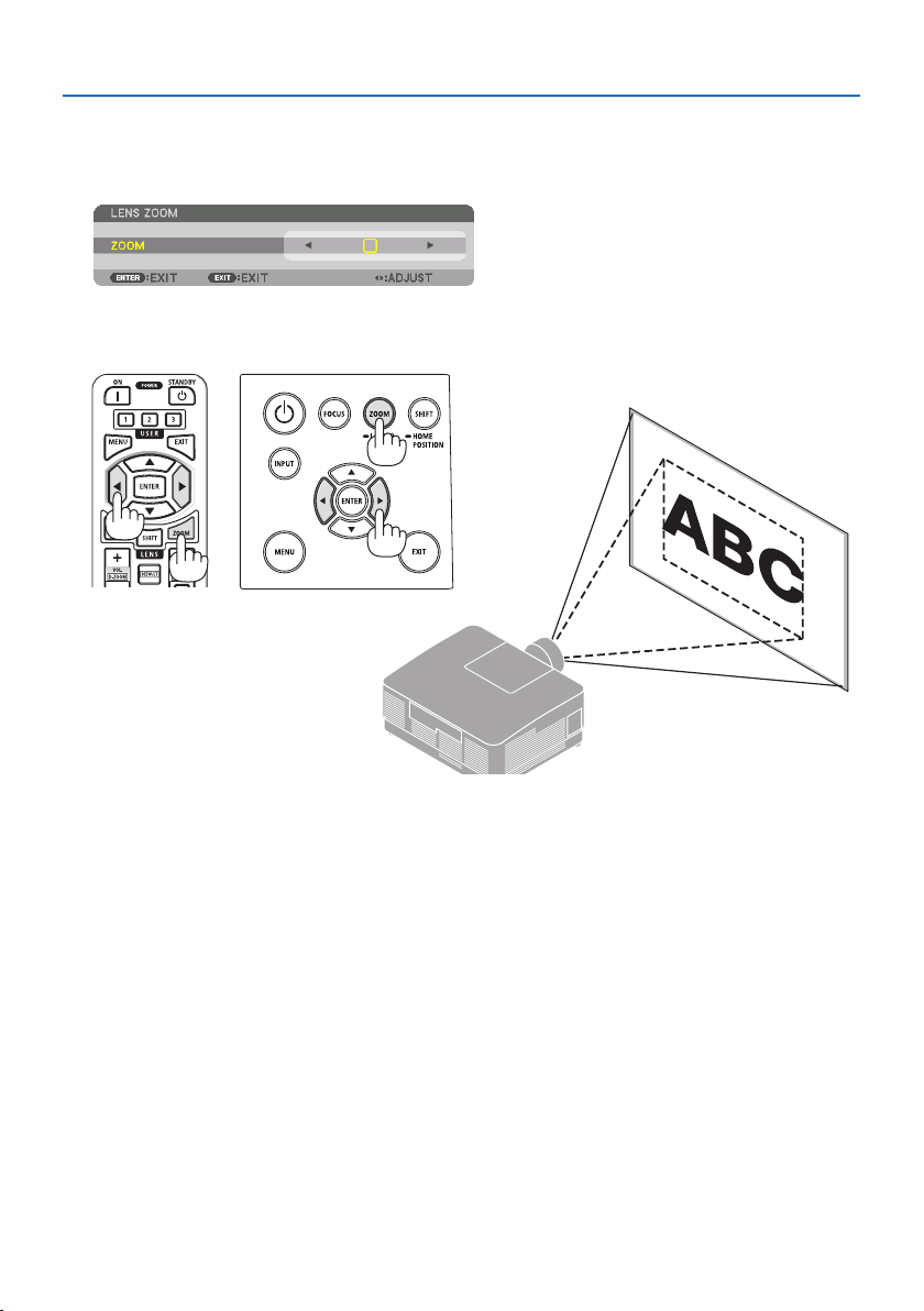
2. Projecting an Image (Basic Operation)
32
Zoom
1. Press ZOOM/L-CALIB. button.
The [ZOOM] adjustment screen will be displayed on.
* In another way, press the ZOOM button on the remote control.
Press ◀▶ buttons to adjust zoom.
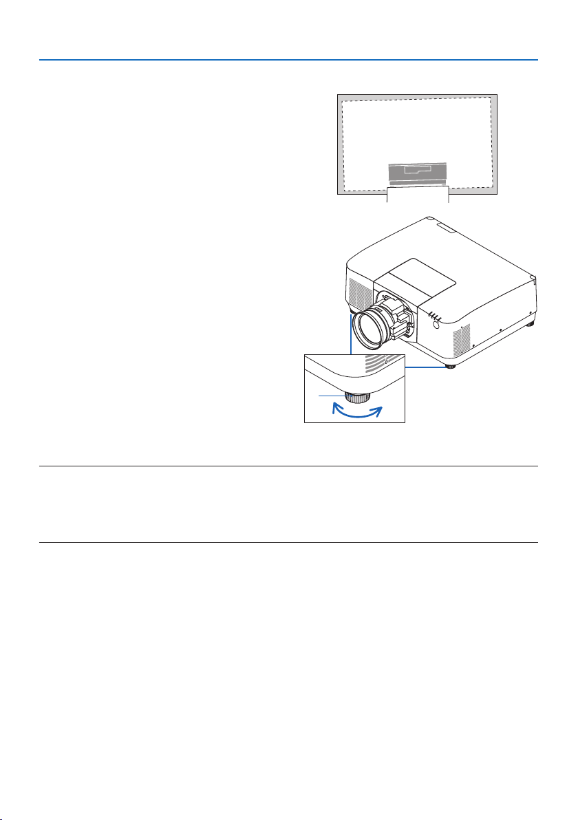
2. Projecting an Image (Basic Operation)
33
Adjusting the Tilt Foot
1. Turn the left and right tilt foot to adjust.
The tilt foot lengthen and shorten when turned.
Turn one of the tilt foot to adjust the image so
that it is level.
• The tilt foot can be lengthened by a maxi-
mum of 10 mm/0.4".
• The tilt foot can be used to tilt the projector
by a maximum of 1.4°.
a
bc
a: Tilt foot / b: Up / c: Down
NOTE:
• Do not lengthen the tilt foot any more than 10 mm/0.4". Doing so will make the projector unstable.
• Do not use the tilt foot for any purpose other than adjusting inclination of the projector installation angle.
Handling the tilt foot improperly, such as carrying the projector by grasping the tilt foot or hooking it onto a wall using the tilt
foot, could damage the projector.
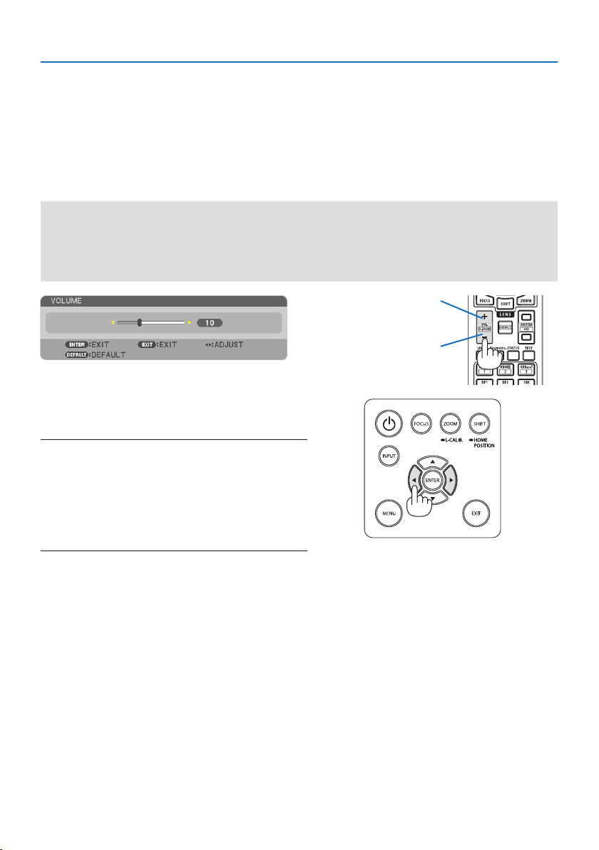
2. Projecting an Image (Basic Operation)
34
2-6. Adjusting a picture and sound
Adjusting the picture
Display [ADJUST] in the on-screen menu and adjust the picture. Refer to the Installation Manual
for details.
Turning Up or Down Volume
Sound level from the AUDIO OUT terminal can be adjusted.
Important:
• Do not turn up the volume to the maximum level on the external speaker system connected to the AUDIO OUT of the projector.
Doing so may produce an unexpected, loud sound at the time of turning on or o the projector, causing damage to your hearing.
When adjusting the volume on the external speaker system, set volume level of the speaker system to less than half its rating and
adjust the volume on the projector to get appropriate sound level.
When no menus appear, the ◀ and ▶ buttons on
the projector cabinet work as a volume control.
• On the remote control, press the VOL./D-ZOOM
(+) or (−)button.
NOTE:
• The volume cannot be adjusted using the ◀ or ▶ button in the
following cases.
• When the on-screen menu is displayed
• When the screen is enlarged by pressing the VOL./D-ZOOM (+)
(−) buttons while holding down the CTL button on the remote
control
X
Increase volume
Decrease volume
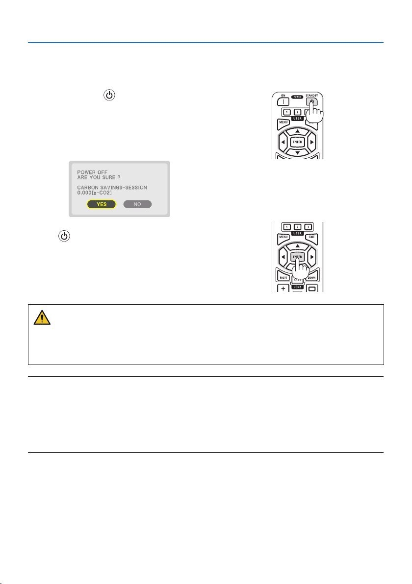
2. Projecting an Image (Basic Operation)
35
2-7. Turning off the Projector
To turn o the projector:
1. First, press the (POWER) button on the
projector cabinet or the STANDBY button on
the remote control.
The [POWER OFF / ARE YOU SURE ? / CARBON
SAVINGS-SESSION 0.000[g-CO2]] message will
appear.
2. Secondly, press the ENTER button or press
the
(POWER) or the STANDBY button
again.
The light source will be turned o and the power
supply will be cut.
CAUTION
• Parts of the projector may become temporarily heated if the projector is turned o with the
POWER button or if the AC power supply is disconnected during normal projector operation.
Use caution when picking up the projector.
NOTE:
• While the POWER indicator is blinking blue in short cycles, the power cannot be turned o.
• Do not unplug the power cord from the projector or from the power outlet while an image is being projected. Doing so could
deteriorate the projector’s AC IN terminal or the power plug’s contact. To turn o the AC power while an image is being projected,
use the breaker, etc.
• Do not disconnect the AC power supply to the projector within 10 seconds of making adjustment or setting changes and closing
the menu. Doing so can cause loss of adjustments and settings.
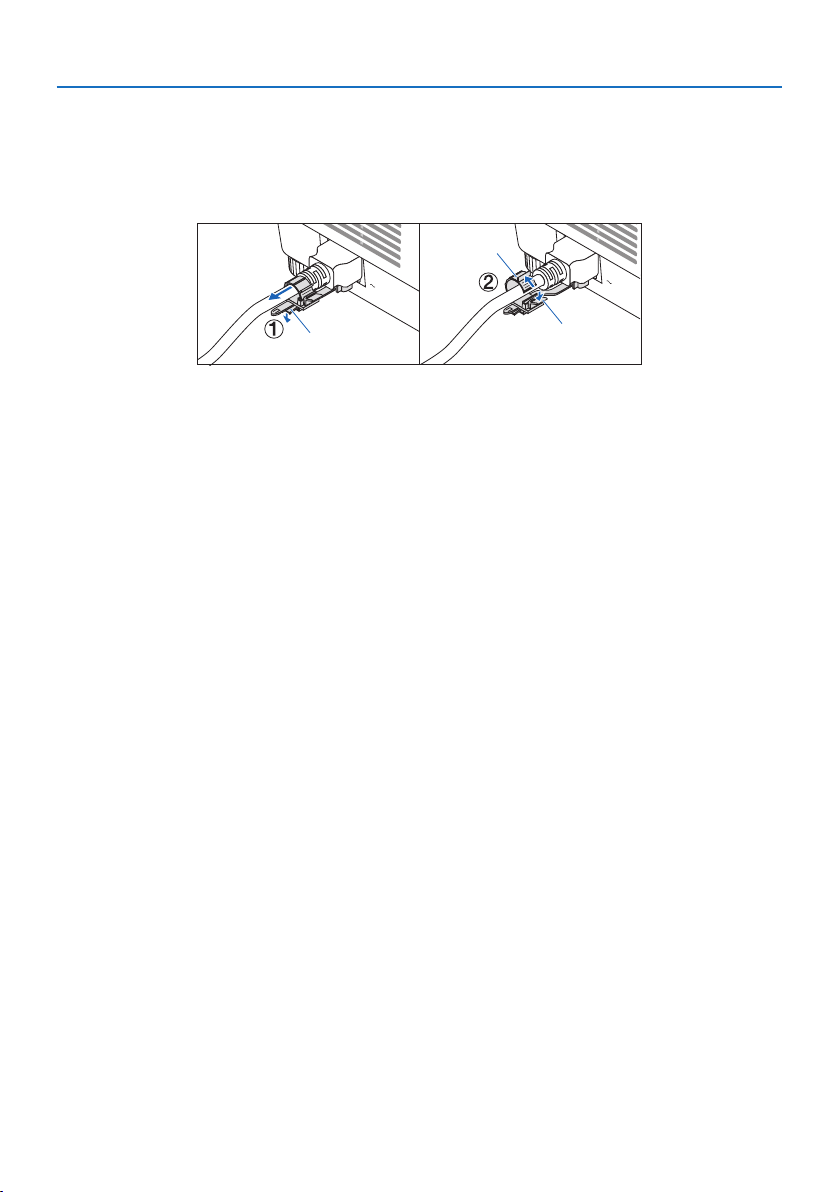
2. Projecting an Image (Basic Operation)
36
2-8. After Use
1. Unplug the power cord.
① Pull to an appropriate position while pushing down the knob of the power cord stopper.
② Press down the knob on the clamper to open the clamper and take out the power cord.
b
c
a
a: Clamper / b: Knob (power cord stopper) / c: Knob (clamper)
2. Disconnect any other cables.
3. Mount the lens cap on the lens.
4. Before moving the projector, screw in the tilt foot if they have been lengthened.
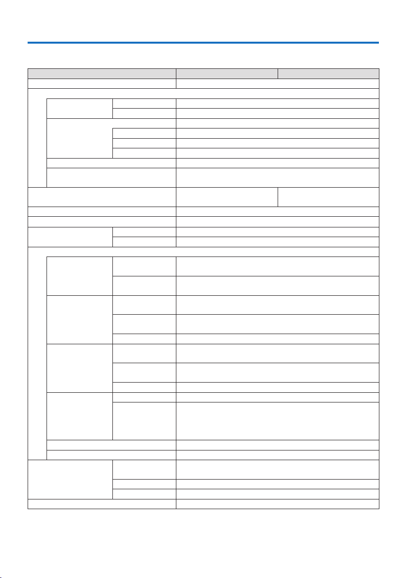
37
3. Appendix
3-1. Specifications
Model name PA1705UL-W/PA1705UL-B PA1505UL-W/PA1505UL-B
Method Three primary color liquid crystal shutter projection method
Specications of main parts
Liquid crystal
panel
Size 1.0" × 3 (aspect ratio: 16:10)
Pixels
(*1)
2,304,000 (1920 dots × 1200 lines)
Projection lenses Refer to the specications of option lens (→ 39 page)
Zoom Motorized
Focus Motorized
Lens shifting Motorized
Light source Laser diode with Phosphor
Optical device Optical isolation by dichroic mirror, combining by dichroic
prism
Light output
(*2)
16000 lm
(*3)
17000 lm (Center)
14000 lm
(*3)
15000 lm (Center)
Screen size (throw distance) 60"–500" (Throw distance depends on the lens)
Color reproducibility 10-bit color processing (approx. 1.07 billion colors)
Scanning frequency Horizontal 15 kHz, 24 to 153 kHz
Vertical 24, 25, 30, 48 Hz, 50 to 85 Hz, 100, 120 Hz
Input/output connectors
HDMI IN 1/2 Video input Type A × 2
Deep Color, LipSync, HDCP
(*4)
, 4K
Audio input Sampling frequency: 32/44.1/48 kHz
Sampling bits: 16/20/24 bit
HDBaseT IN Video input RJ-45 x1,
Deep Color, LipSync, HDCP
(*4)
, 4K
Audio input Sampling frequency: 32/44.1/48 kHz
Sampling bits: 16/20/24 bit
Control 100BASE-TX, Art-Net, PJLink class2
HDBaseT OUT
Video output RJ-45 x1,
Deep Color, LipSync, HDCP
(*4)
, 4K
Audio output Sampling frequency: 32/44.1/48 kHz
Sampling bits: 16/20/24 bit
Control 100BASE-TX, Art-Net, PJLink class2
SDI IN
Video input BNC x1 3G/HD/SD
Audio input 2ch Setereo Audio
Audio Channel1 : L ch
Audio Channel2 : R ch
Sampling frequency : 48kHz
AUDIO OUT Stereo mini jack × 1 (Common to all signals)
USB USB type A × 1, 5.0 V/1.4 A power supply
Control Terminals LAN RJ-45 × 1, 10BASE-T/100BASE-TX,
Art-Net, PJLink class2
PC CONTROL D-Sub 9-pin × 1, RS232C
REMOTE Stereo mini jack × 1
Built-in Speaker Not applicable

3. Appendix
38
Model name PA1705UL-W/PA1705UL-B PA1505UL-W/PA1505UL-B
Usage environment
(*5)
Operating temperature: 32 to 113°F (0 to 45°C)
Operating humidity: 20 to 80% (with no condensation)
Storage temperature: 14 to 122°F (−10 to 50°C)
Storage humidity: 20 to 80% (with no condensation)
Operating altitude: 0 to 3650 m/12000 feet
Power supply 100-240 V AC, 50/60 Hz
Power consumption 1035 W (100-130 V AC)
995 W (200-240 V AC)
960 W (100-130 V AC)
925 W (200-240 V AC)
Power consumption
(Standby state)
Network enabled 0.4 W (100-130 V AC) / 0.5 W (200-240 V AC)
Network disabled 0.15 W (100-130 V AC) / 0.20 W (200-240 V AC)
Rated input current 12.8 A (100-130 V AC)
5.6 A (200-240 V AC)
11.6 A (100-130 V AC)
5.1 A (200-240 V AC)
Power cord specication 15 A or higher
External dimensions 23.6" (width) × 9.0" (height) × 19.3" (depth)/
599 (width) × 230 (height) × 490 (depth) mm
(not including protruding parts)
23.6" (width) × 9.4" (height) × 19.3" (depth)/
599 (width) × 238 (height) × 490 (depth) mm
(including protruding parts)
Weight 63.3 lbs/28.7 kg
(not including lens)
*1 Eective pixels are more than 99.99%.
*2 This is the brightness when lens unit NP54ZL (sold separately) is attached and [REF. LIGHT MODE] is set to
[NORMAL], [REF. LIGHT ADJUST] is set to [100], and [PRESET] is set to [HIGH-BRIGHT]. Using [LIGHT ADJUST]
will reduce brightness. If any other mode is selected as the [PRESET] mode, the light output value may drop
slightly.
*3 Compliance with ISO21118-2020
*4 If you are unable to view material via the HDMI input, this does not necessarily mean the projector is not
functioning properly. With the implementation of HDCP, there may be cases in which certain content is
protected with HDCP and might not be displayed due to the decision/intention of the HDCP community
(Digital Content Protection, LLC).
Video: HDR, Deep Color, 8/10/12-bit, Lip Sync.
Audio: LPCM; up to 2 ch, sample rate 32/44.1/48 KHz, sample bit; 16/20/24-bit
HDMI: Supports HDCP 2.2/1.4
HDBaseT: Supports HDCP 2.2/1.4
*5 The projector’s protection functions will activate depending on the temperature of the operating environ-
ment.
• For additional information visit:
US: https://www.sharpnecdisplays.us
Europe: https://www.sharpnecdisplays.eu
Global: https://www.sharp-nec-displays.com/global/
For information on our optional accessories, visit our website or see our brochure.
The specications are subject to change without notice.
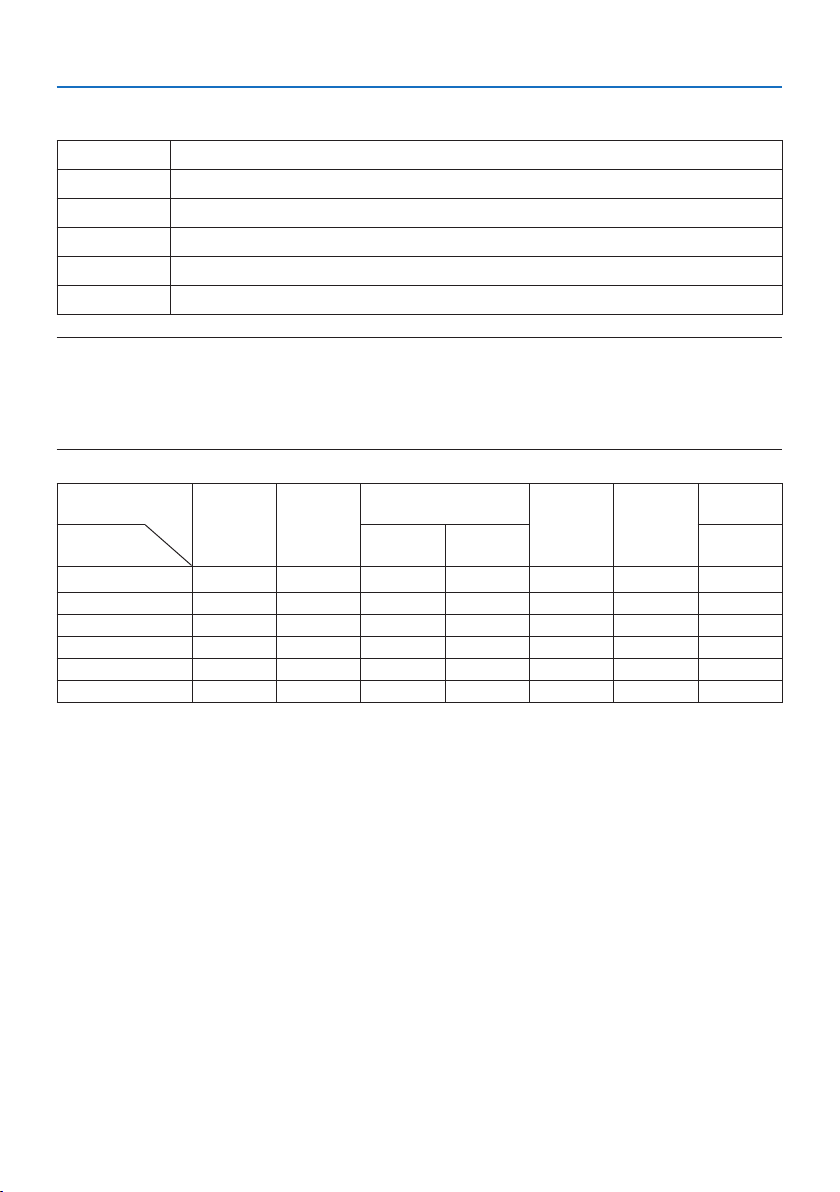
3. Appendix
39
Option lens (sold separately)
NP51ZL Throw ratio 0.53–0.65 : 1, F1.85–2.20, f=12.0-14.6 mm
NP52ZL Throw ratio 0.65–0.87 : 1, F1.84–2.25, f=14.4-19.1 mm
NP53ZL Throw ratio 0.86–1.25 : 1, F1.80–2.24, f=19.0-27.6 mm
NP54ZL Throw ratio 1.24–2.01 : 1, F1.80–2.24, f=27.7-44.3 mm
NP55ZL Throw ratio 1.98–3.95 : 1, F1.84–2.58, f=43.8-86.0 mm
NP56ZL Throw ratio 3.92–7.50 : 1, F1.80-2.40, f=86.0-165.0 mm
NOTE:
• The above throw ratio is for projecting on 100" screen.
• NP51ZL, NP52ZL, and NP56ZL will be available on market after April 2024. The values for NP51ZL, NP52ZL, and NP56ZL on this
manual are tentative, please contact your dealer about their detailed information or refer to the latest manual uploaded on our
web site.
Function
Motorized
lens shift
Motorized
zoom
Motorized focus
LENS
CALIBRATION
Home
position
REF. LENS
MEMORY
Lens model
name
CENTER PERIPHERY
LENS
MEMORY
NP51ZL Yes Yes Yes Yes Yes Yes Yes
NP52ZL Yes Yes Yes Yes Yes Yes Yes
NP53ZL Yes Yes Yes Yes Yes Yes Yes
NP54ZL Yes Yes Yes No Yes * Yes Yes *
NP55ZL Yes Yes Yes No Yes * Yes Yes *
NP56ZL Yes Yes Yes No Yes * Yes Yes *
* Except [PERIPHERY] focus
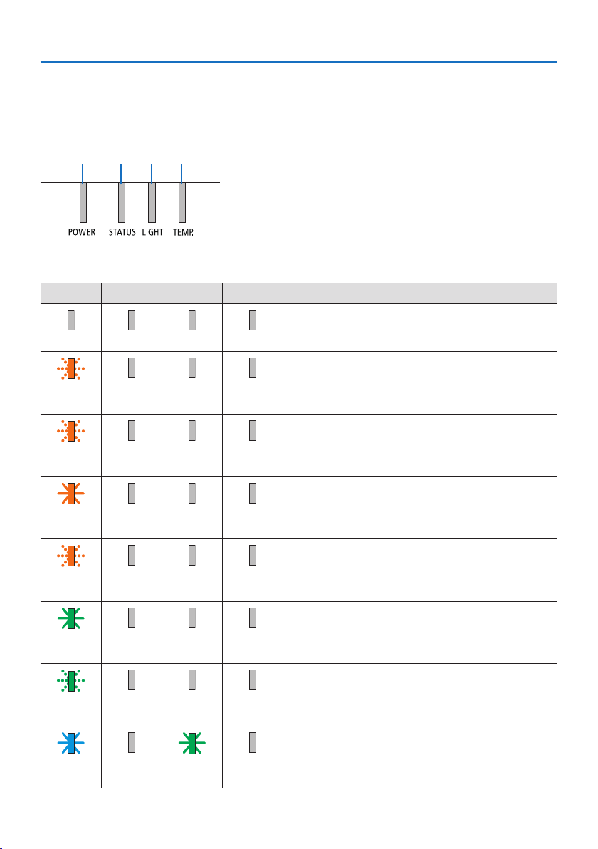
3. Appendix
40
3-2. Troubleshooting
This section helps you resolve problems you may encounter while setting up or using the projector.
Feature of each indicator
① ② ③ ④
① POWER indicator
②
STATUS indicator
③
LIGHT indicator
④
TEMP. indicator
Indicator Message (Status message)
POWER STATUS LIGHT TEMP. Projector status
Power is o
O O O O
In the state of Standby ([POWER-SAVING] is [ON] and
the network is ready.
Orange
(Blink*
1
)
O O O
In the state of Standby ([POWER-SAVING] is [ON] and
the network is unavailable.
Orange
(Blink*
2
)
O O O
In the state of Standby ([POWER-SAVING] is [ON] and
the network is available)
Orange
(Light)
O O O
[ON] time as the [PROGRAM TIMER] is activated. (In the
state of Standby)
Orange
(Blink*
3
)
O O O
In the state of Sleep
Green
(Light)
O O O
[ON] time as the [PROGRAM TIMER] is activated. (In the
state of Sleep)
Green
(Blink*
3
)
O O O
Powered state ([REF. LIGHT MODE] is [NORMAL])
Blue
(Light)
O Green
(Light)
O
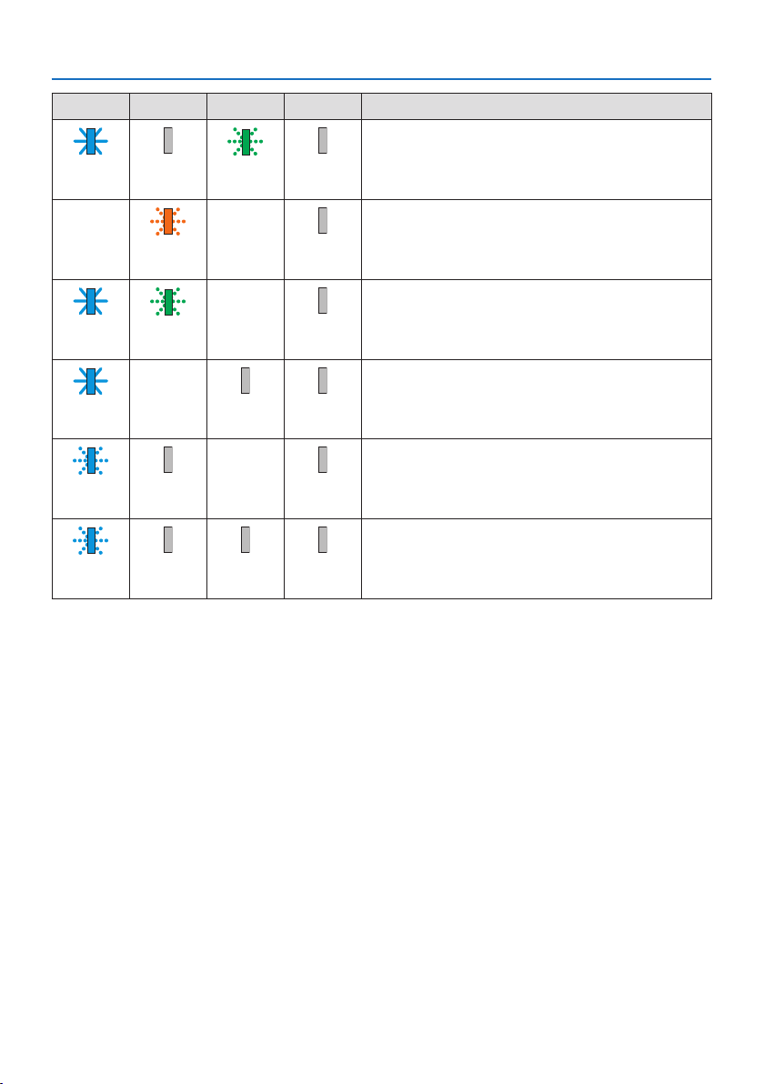
3. Appendix
41
POWER STATUS LIGHT TEMP. Projector status
Powered state ([REF. LIGHT MODE] is [SILENT] or [LONG
LIFE])
Blue
(Light)
O Green
(Blink*
3
)
O
[LENS CALIBRATION] implement request.
Status varies Orange
(Blink*
4
)
Status varies O
Performing the lens calibration
Blue
(Light)
Green
(Blink*
4
)
Status varies O
Shutter function is activating
Blue
(Light)
Status varies O O
[OFF TIMER] is activated, [OFF] time as the [PROGRAM
TIMER] is activated (Powered state)
Blue
(Blink*
3
)
O Status varies O
Preparing for powering [ON]
Blue
(Blink*
5
)
O O O
*1 Repetition to light on for 1.5 seconds / o for 1.5 seconds
*2 Repetition to light on for 1.5 seconds / o for 7.5 seconds
*3 Repetition to light on for 2.5 seconds / o for 0.5 seconds
*4 Repetition to light on for 0.5 seconds / o for 0.5 seconds / on for 0.5 seconds / o for 2.5 seconds
*5 Repetition to light on for 0.5 seconds / o for 0.5 seconds
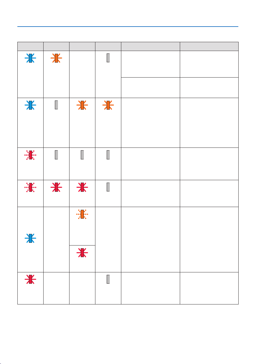
3. Appendix
42
Indicator Message (Error message)
POWER STATUS LIGHT TEMP. Projector status Procedure
A button has been
pressed while the [CON-
TROL PANEL LOCK] is
activated.
The [CONTROL PANEL
LOCK] is activated. The
setting must be canceled
to operate the projector.
Blue
(Light)
Orange
(Light)
Status varies O
ID numbers for the
projector and the remote
control do not match.
Check the [CONTROL ID]
Temperature problem Ambient temteprature
is high. The projector's
protection functions will
activate depending on
the temperature of the
operating environment.
Lower the room tempera-
ture.
Blue
(Light)
O Orange
(Light)
Orange
(Light)
Temperature problem Ambient temperature
is out of the operation
temperature. Check if any
obstruction stays near the
exhaust vent.
Red
(Blink*
5
)
O O O
Lens mounting error Lens is not mounted
properly. Mount it.
Red
(Blink*
5
)
Red
(Light)
Red
(Light)
O
Error requiring service
support
Although the projector
can still be used, we rec-
ommend that you contact
your dealer or service
personnel and request an
inspection.
Orange
(Blink*
3
)
or
(Blink*
5
)
Blue
(Light)
Status varies
Status varies
Red
(Light)
Error requiring service
support
Contact your dealer or
service personnel. Make
sure to check and inform
indicator status for asking
to repair.
Red
(Light)
Status varies Status varies O
*3 Repetition to light on for 2.5 seconds / o for 0.5 seconds
*5 Repetition to light on for 0.5 seconds / o for 0.5 seconds

3. Appendix
43
When the thermal protector is activated:
When inside temperature of the projector becomes too high or low, the POWER indicator start to
red blink in a short cycle. After this happened, the thermal protector will activate and the projector
may be turned o.
In this case, please take the below measures:
• Pull out the power plug from the wall inlet.
• Place the projector in cool place if it has been placed in high ambient temperature.
• Clean the exhaust vent if dust has accumulated on.
• Leave the projector for about one hour until inside temperature gets lower.

3. Appendix
44
Common Problems & Solutions
Problem Check These Items
Does not turn on or shut
down
• Check that the power cord is plugged in and that the power button on the projector cabinet or the
remote control is on.
• Check to see if the projector has temperature error, If projector inside temperature is too hot or cool,
it disabled to turn on the projector as the protection. Wait for a moment and try turn on the projector
again.
• In case it’s hard to think the trouble is not caused on the above mentioned conditions, unplug the
power cord from the outlet. Then wait 5 minutes before plugging it in again.
Will turn o
• Ensure that the [OFF TIMER], [AUTO POWER OFF] or [PROGRAM TIMER] is o.
No picture
• Check if the appropriate input is selected. If there is still no picture, press the INPUT button or one of
the input buttons again.
• Ensure your cables are connected properly.
• Use menus to adjust the brightness and contrast.
• Is the [POWER ON SHUTTER] in the on-screen menu set to [CLOSE]?
• Check that the SHUTTER CLOSE button is not pressed.
• Reset the settings or adjustments to factory preset levels using the [RESET] in the Menu.
• Enter your registered keyword if the Security function is enabled.
• If the HDMI input signal cannot be displayed, try the following.
Reinstall your driver for the graphics card built in your computer, or use the updated driver.
For reinstalling or updating your driver, refer to the user guide accompanied with your computer or
graphics card, or contact the support center for your computer manufacturer.
Install the updated driver or OS on your own responsibility.
We are not liable for any trouble and failure caused by this installation.
• The signal may not be supported depending on the HDBaseT transmission device. In addition, RS232C
interface may not be supported.
• If the projector is kept in sleep mode or other similar state, the temperature of the internal compo-
nents could rise even when the projector is being used within its normal operating temperate. If the
power is ON when that occurs, the cooling fan will turn on and it will take a little bit of time before
the image is projected. Please wait for a while.
Picture suddenly becomes
dark
• A hot room may trigger the projector's protection functions, which can result in a temporary reduction
in luminance (brightness). Reduce the temperature in the room.
Color tone or hue is unusual
• Check if an appropriate color is selected in [WALL COLOR]. If so, select an appropriate option.
• Adjust [HUE] in [PICTURE].
Image isn’t square to the
screen
• Reposition the projector to improve its angle to the screen.
• Perform [GEOMETRIC CORRECTION] when the trapezoid is distorted.
Picture is blurred
• Adjust the focus.
• Reposition the projector to improve its angle to the screen.
• Ensure that the distance between the projector and screen is within the adjustment range of the
lens.
• Has the lens been shifted by an amount exceeding the guaranteed range?
• Condensation may form on the lens if the projector is cold, brought into a warm place and is then
turned on. Should this happen, let the projector stand until there is no condensation on the lens.

3. Appendix
45
Problem Check These Items
Image is scrolling vertically,
horizontally or both
• Check the computer’s resolution and frequency. Make sure that the resolution you are trying to display
is supported by the projector.
• Adjust the computer image manually with the Horizontal/Vertical in the [IMAGE OPTIONS].
Remote control does not
work
• Aim the remote control's infrared transmitter towards the projector's remote control receiver.
• Install new batteries.
• Make sure there are no obstacles between you and the projector.
• Stand within 20 m/787 inch of the projector.
• If a [CONTROL ID] has been set, check whether the ID number for the remote control matches the ID
number for the projector.
On-screen menu is not
displayed
• Check whether On-screen mute is active.
On-screen mute can be turned o using one of the following ways:
- Press the OSD OPEN button while holding down the CTL button on the remote control.
- Holding down the MENU button on the projector cabinet for at least 10 seconds.
Indicator is lit or blinking
• See the Indicator Message.
For more information contact your dealer.
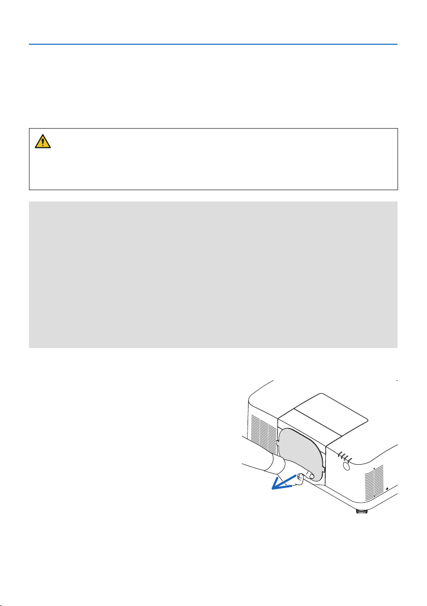
3. Appendix
46
3-3. Mounting a lens (sold separately)
Six separate bayonet style lenses can be used with this projector. The descriptions here are for the
NP54ZL lens. Mount other lenses in the same manner.
After installing or replacing the lens unit, press the ZOOM/L-CALIB. button on the projector to carry
out [LENS CALIBRATION]. By carrying out [LENS CALIBRATION], the adjustment range of the lens
shift is calibrated.
WARNING:
(1) Turn o the power and wait for the cooling fan to stop, (2) disconnect the power cord and
wait for the unit to cool before mounting or removing the lens. Failure to do so can result in eye
injury, electric shock, or burn injuries.
Important:
• The projector and lenses are made of precision parts. Do not subject them to shock or excessive forces.
• Remove the separately sold lens when moving the projector. If not, the lens could be subject to shock while the projector is being
moved, damaging the lens and the lens shift mechanism.
• If the projector must be moved with the lens unit attached, such as when it is installed in a high or specic location, use the screws
included with the lens unit to secure it to the projector. Do not hold the lens when moving the projector.
• When dismounting the lens from the projector, return the lens position to the home position before turning o the power. Failure
to do so may prevent the lens from being mounted or dismounted because of narrow space between the projector and the lens.
• Never touch the lens surface while the projector is operating.
• Be very careful not to let dirt, grease, etc., on the lens surface and not to scratch the lens surface.
• Perform these operations on a at surface over a piece of cloth, etc., to prevent the lens from getting scratched.
• When leaving the lens o the projector for long periods of time, mount the dust cap on the projector to prevent dust or dirt from
getting inside.
Mounting
1. Remove the dust cap from the projector.
Pull on the bottom edge of the dust cap with
your ngers.
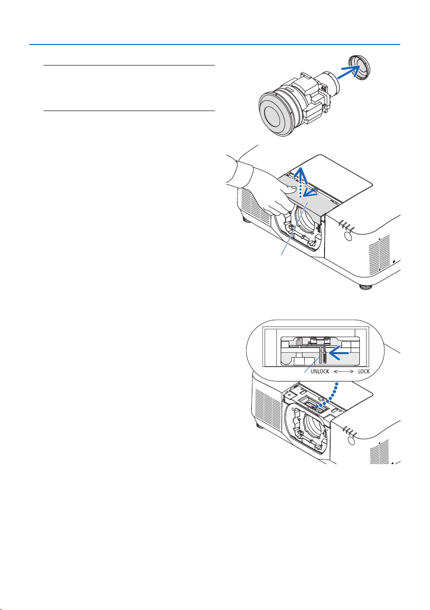
3. Appendix
47
2. Remove the lens cap on the back of the lens.
NOTE:
• Make sure to remove the lens cap at the unit back side. If
the lens unit with the lens cap remaining on is installed
on the projector, it may cause of malfunction.
3. Remove the lens cover.
Pull the cover about 2 cm forward, then lift
it up.
a
a: Lens cover
4. Check that the lens lock lever is in the UN-
LOCK position.
If it is in the LOCK position, press the right
side of the lens lock lever to move it to the
UNLOCK position.
b
b: Lens lock lever
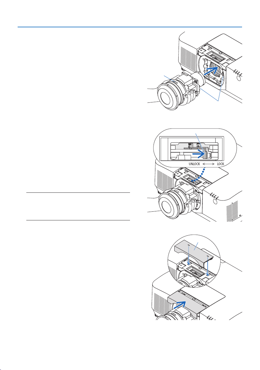
3. Appendix
48
5. With the plate on the lens unit facing up,
insert the lens unit into the projector's lens
hole.
Align the position of the connector and gently
insert it as far back as possible.
c
d
c: Plate / d: Connector
6. While supporting the lens unit with your
hand, press the left side of the lens lock
lever towards the LOCK position until it
stops.
A clicking sound will conrm that the lens unit
is attached to the projector body.
The left and right parts of the lens lock lever
will open when the lens unit is attached cor-
rectly.
NOTE:
• The lens unit will not lock in place if it is tilted. Move the
lens lock lever while the lens unit is still attached to the
lens hole.
b
b: Lens lock lever
7. Attach the lens cover to the projector.
(1) Leave a gap of about 2 cm when attaching
the lens cover.
(2) Push it in the direction of the arrow.
a
a: Lens cover
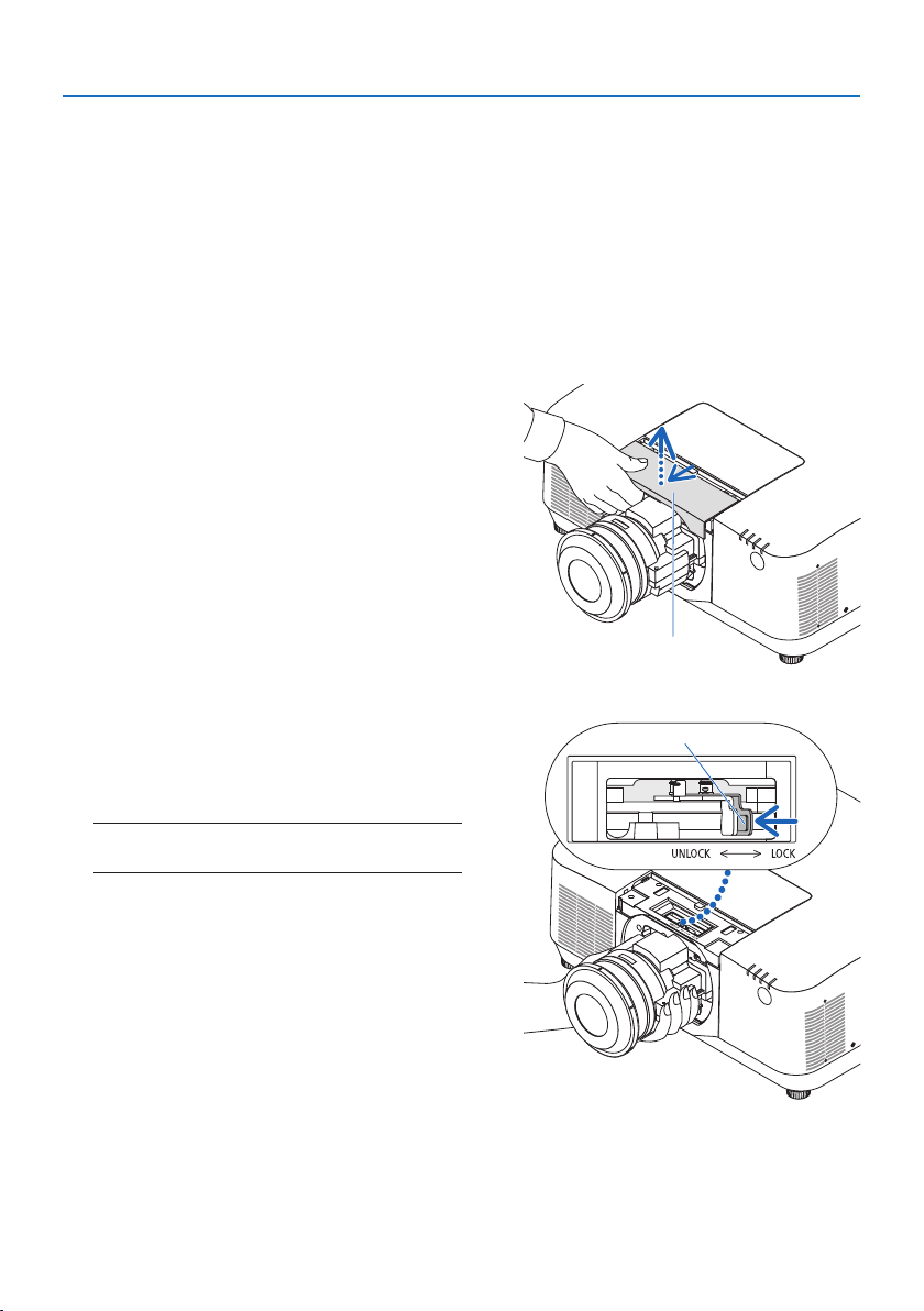
3. Appendix
49
Removing
Preparations:
1. Turn on the projector and display an image.
2. Press and hold the SHIFT/HOME POSITION button over 2 seconds. The lens position will be
moved to the home position.
3. Turn o the main power switch, and then unplug the power cord.
4. Mount the lens cap on the lens.
5. Wait until the projector cabinet is cool enough to handle.
1. Remove the lens cover.
Pull the cover about 2 cm forward, then lift
it up.
a
a: Lens cover
2. While supporting the lens unit with one
hand, press the right side of the lens lock
lever towards the UNLOCK position until it
stops.
NOTE:
• Hold the lens unit securely to prevent it from falling.
b
b: Lens lock lever
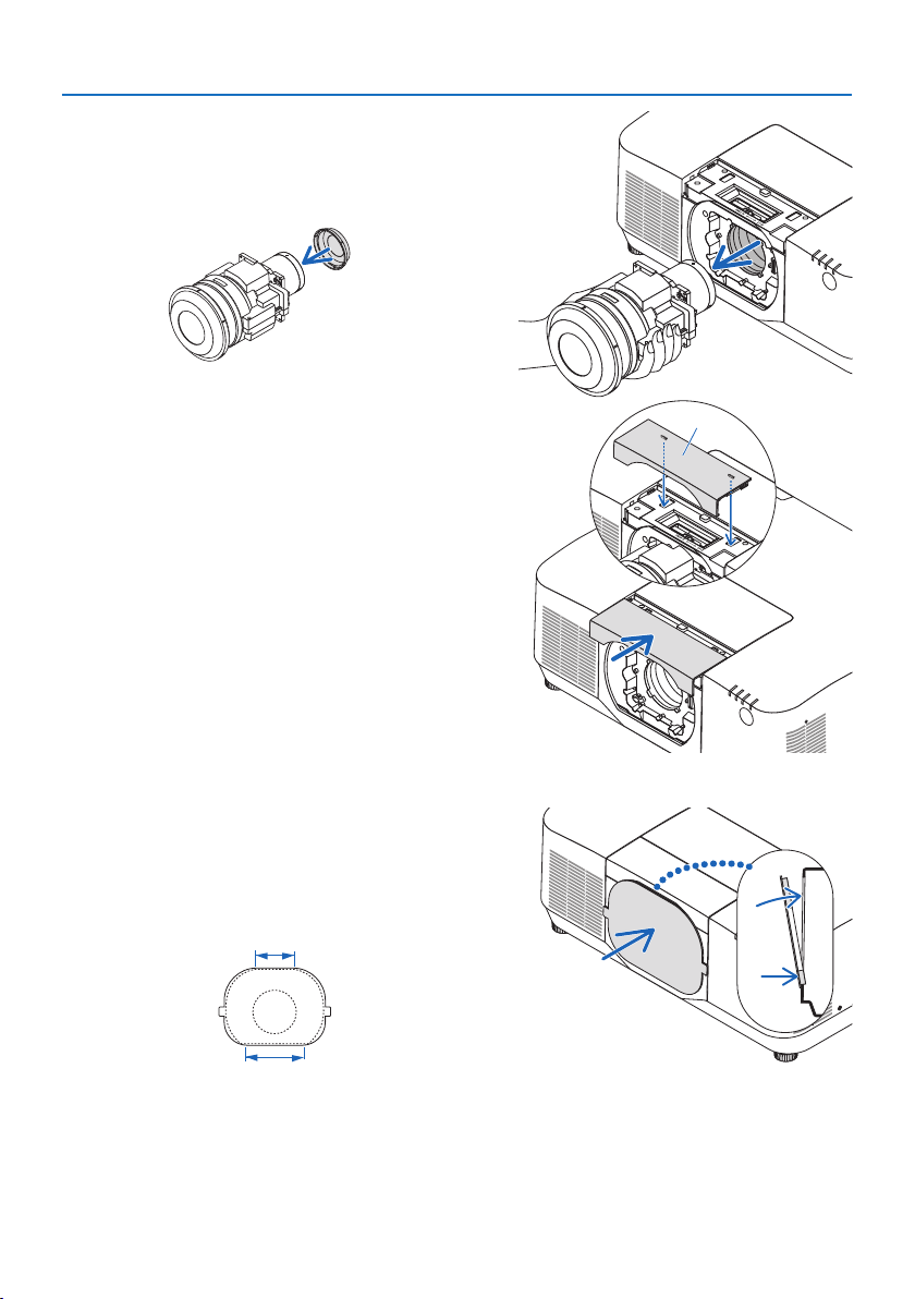
3. Appendix
50
3. Gently pull the lens unit out from the pro-
jector.
Once the lens unit has been removed, attach
the rear lens cap included with the lens unit
before storing.
4. Attach the lens cover to the projector.
(1) Leave a gap of about 2 cm when attaching
the lens cover.
(2) Push it in the direction of the arrow.
a
a: Lens cover
* When not attaching a lens unit, attach the dust
cap supplied with the projector.
Align the dust cap with the projector body, place
the lower section on the projector, then push the
surrounding area.
The bottom side of the dust cover is the side
with the longer at area.

© Sharp NEC Display Solutions, Ltd. 2023
REGISTER YOUR PROJECTOR! (for residents in the United States, Canada,
and Mexico)
Please take time to register your new projector. This will activate your limited parts and labor war-
ranty and InstaCare service program.
Visit our web site at https://www.sharpnecdisplays.us, click on support center/register product and
submit your completed form online.
Upon receipt, we will send a conrmation letter with all the details you will need to take advantage
of fast, reliable warranty and service programs from the industry leader, Sharp NEC Display Solu-
tions of America, Inc.