Loading ...
Loading ...
Loading ...
Installation
10
Gas Connection
NOTE: ALL GAS FITTING MUST ONLY BE CARRIED OUT BY AN QUALIFIED SERVICE PERSON.
1. It is essential that gas supply is correct for appliance to be installed and that adequate supply
pressure and volume are available. The following checks should be made before installation:-
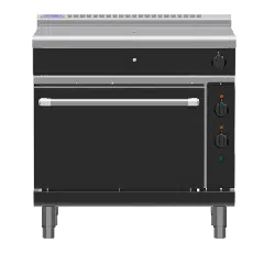
a. Gas Type the appliance has been supplied for is shown on
coloured stickers located above gas connection and onrating
plate. Check this is correct for gas supply the appliance is being
installed for. Gas conversion procedure is detailed in this
manual.
b. Supply Pressure required for this appliance is shown in
‘Specifications’ section in this manual. Check gas supply to
ensure adequate supply pressure exists.
c. The Input Rate of this appliance is shown on Rating Plate and
in ‘Specifications’ section in this manual. Input rate should be
checked against available gas supply line capacity. Particular
note should be taken if appliance is being added to an
existing installation.
NOTE: It is important that adequately sized piping runs directly to connection joint on appliance
with as few tees and elbows as possible to give maximum supply volume.
2. Fit gas regulator supplied, into gas supply line as close to appliance as possible.
NOTE: Gas pressure regulator provided with this appliance is convertible between Natural Gas and
LPG as per ‘Gas Conversion Section’ in this manual.
Ensure regulator is converted to correct gas type that appliance will operate on.
Regulator outlet pressure is fixed ex-factory for gas type that regulator is converted to and it
is NOT to be adjusted.
Regulator connections are
3
/
4
" BSP female.
Connection to appliance is
3
/
4
" BSP male.
(Refer to ‘Specifications’ section for gas supply location dimensions).
NOTE: A Manual Isolation Valve must be fitted to individual appliance supply line.
3. Correctly locate appliance into its final operating position and using a spirit level, adjust legs so that
appliance is level and at correct height.
4. Connect gas supply to appliance. A suitable joining compound which resists breakdown action of
LPG must be used on every gas line connection, unless compression fittings are used.
5. Check gas operating pressure is as shown in ‘Specifications’ section.
6. Check all gas connections for leakages using soapy water or other gas detecting equipment.
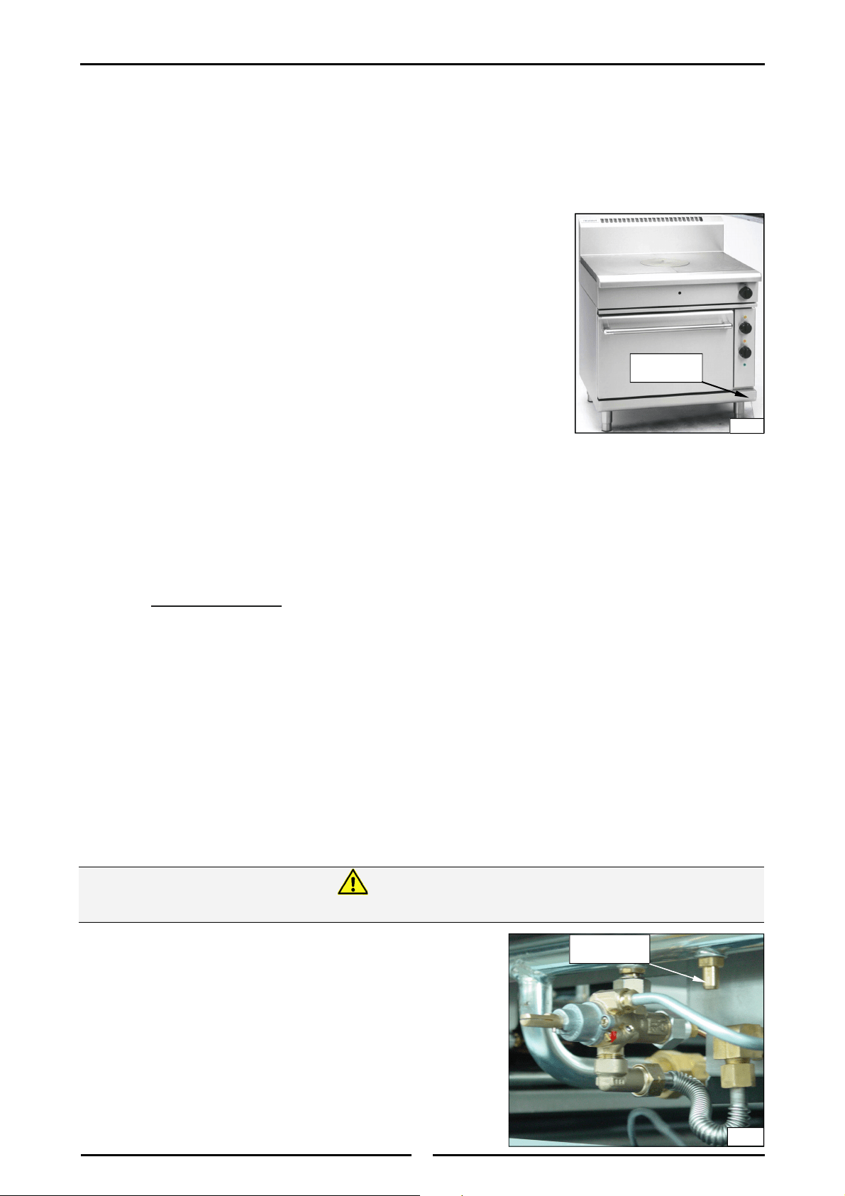
NOTE: Measure burner operating pressure at target top
hob manifold test point with target top burner (Inner
and outer ring) operating at full setting.
7. Verify operating pressure remains correct.
Rating Plate
Location
Fig 2
Fig 3
Manifold Test
Point
DO NOT USE A NAKED FLAME TO CHECK FOR GAS LEAKAGES.
Warning
Loading ...
Loading ...
Loading ...