The world’s most powerful color correction now on
Linux and Mac!
DaVinci color correctors have been the standard in
post production since 1984. There are thousands
of colorists worldwide who understand the
performance, quality and workflow of DaVinci.
DaVinci is the name behind more feature films,
television commercials, documentaries, television
production and music videos than any other
grading system.
When you’re in a room full of demanding clients
with conflicting ideas, colorists know that DaVinci
Resolve has the quality, real time performance,
creative features, and powerful control panel you
need to work fast! DaVinci Resolve is now available
for both Mac OS X and the clustered super
computer power of Linux!
Welcome to DaVinci Resolve 8
CONTENTS
USER MANUAL
DAVINCI RESOLVE USER MANUAL
Introduction 14
Introducing DaVinci Resolve 15
What’s New in DaVinci Resolve 8 16
System Setup 22
Media Storage Volumes 23
Video Capture Hardware 24
Control Panel Type 24
Quick Start Guide 26
Quick Start Project 34
Control Panels 36
Getting Started 40
Starting DaVinci Resolve 41
User Login Screen 41
Login To An Existing User 41
Exiting Resolve 41
Creating A New User 42
Deleting An Existing User 42
Changing A User Password 43
Multiple Database Support 43
Selecting the Database 43
Creating a New Database 44
Create a New Database Image 45
Remote Database Server 45
Optimizing a Database 45
Backing up a Database 45
Restoring a Database 45
Configuration 48
The User List 50
The Configuration List 51
Modifying and Saving an Existing Configuration 51
Creating a Facility Default Configuration 52
Projects List 52
Shared Database And Locked Projects 54
Configuration Screen Tabs 55
Project Tab 56
Timeline Format 56
Image Format Scaling 57
Common use of Input Format Preset 58
Deck Capture and Playback 58
Input Scaling 60
Low Resolution Proxies 61
Chapter 1
Chapter 2
Chapter 3
Chapter 4
Chapter 5
Chapter 6
DaVinci Resolve 8

DAVINCI RESOLVE USER MANUAL
Timeline Conform Options 62
Conforming by Reel Number 63
Reel Number Support from Final Cut Pro EDLs 65
Changing the Conform Frame Rates 65
Video Monitoring 66
LUTs Tab 68
Timeline Lookup Tables 68
Generate Soft Clip LUT 69
Generate LUT from Current Grade 69
Apply LUT to Waveform 71
Printer Light Step Calibration 71
Settings Tab 72
Project Settings 73
Dynamic Profiles 76
Timeline Ripple Mode 76
Working Folders 77
Control Panel 78
Autosave Tab 79
Source Tab 80
Master Decode Settings 81
Image Decode Settings 82
Project Image Decoder Settings 83
Browse 86
Media Storage 88
Splitting Clips Based on an EDL 89
Add Material into the Media Pool Based on an EDL 90
Offsetting the Source Timecode from a Clip 91
Copy and Paste Function For Clips 91
Disk Speed Benchmarking 92
Clip Details 93
Add as an Offline Clip 94
Add into Proxy Manager 94
Scene Cut Detector 94
Changing the Source Timecode In Header 95
Converting a Clip to another File Format 96
Add as Matte 96
Extract Audio From QuickTime 97
The Media Pool 98
Media Pool Folders 98
Media Pool Clips 99
Remove selected Clips 100
Remove from Master Session 100
Remove all Clips 100
Set Reel Number 101
Change Pixel Aspect Ratio 101
Chapter 7

CONTENTS
USER MANUAL
DAVINCI RESOLVE USER MANUAL
Source Flip 101
Change Input Format Preset 102
Change Parent Directory 103
Switch Parent Directory 104
The .deleted Folder 104
Clip Replacement and Automatic Proxy Generation 105
Viewer Window 106
Browse Screen Buttons 107
Clip Task Manager 107
Proxy Manager 108
Conform 110
Overview of the Conform Page 111
Controls of the Conform Page 112
The Media Pool 112
The Timeline Management List 113
The Conform EDL List 115
The Source, Offline, and Timeline Tabs 117
The Timeline 119
The Master Timeline 122
Creating and Importing Sessions 123
Creating the Master Session 123
Creating a Blank Session 124
Importing EDL Files 124
Conforming EDLs to Discrete Media Files 125
Conforming EDLs to “Flattened” Master Media Files 125
About AAF Import 129
About XML Import 130
Supported Effects 130
Unsupported Effects 130
Effects Processing When Finishing in DaVinci Resolve 131
Effects Processing in Round-Trip Workflows 131
Importing AAF and XML Files 132
Dealing With Reel Conflicts 136
Exporting Sessions 139
Rendering Media to Accompany Exported Projects 139
Creating a Session With Handles 139
Exporting EDLs 141
Exporting XML Files Back to Final Cut Pro 141
Exporting CDL Files 142
Exporting ALE Files 143
Editing in Source/Timeline Mode 144
Simple Editing 144
Finding Media 148
Replacing Media in the Timeline 149
Chapter 8
DaVinci Resolve 8

DAVINCI RESOLVE USER MANUAL
Reconform From Folders 150
Force Conform 152
Working with Transitions 152
Working With Effects 153
Composite Modes 153
Speed Effects 154
Syncing Sessions to Audio 155
Making Comparisons in Offline/ Timeline Mode 158
Setting Up an Offline/Timeline Comparison 160
Adjusting the Offline/Timeline Sync Offset 160
Alternate Online and Offline Comparison Modes 160
Using ColorTrace™ to Apply Grades From One Project to Another 161
Using ColorTrace™ in Automatic Mode 162
Using ColorTrace™ in Manual Mode 165
Importing CDL Data Using ColorTrace™ 167
Example CMX EDL File 168
Example CCC file: 169
Example CDL file: 169
Color 172
Viewer 174
Interactive Dirt & Dust Removal Tool 176
Viewer Window Options 177
Viewer Stills Display 178
PlayHeads 179
Creating a Stereoscopic Project 179
PlayHeads Via the DaVinci Resolve Control Panel 182
3D Display Modes 185
Waveform displays 186
Show Timecode at 30 fps 186
Stills, PowerGrade and Memories 187
Stills 188
Copying Grades From Stills 190
Preserving Nodes and Parameters When Copying Grades 190
Append Grade 191
Copying Individual Nodes From Stills 192
Export and Import Stills with DaVinci Resolve eXchange (DRX)
color correction metadata 193
Sorting Stills 193
Other Still Options 194
Searching For Stills 194
PowerGrade 195
Memories 196
Node Graph 197
Managing Nodes 198
Manually Connecting Corrector Nodes 200
Chapter 9

CONTENTS
USER MANUAL
DAVINCI RESOLVE USER MANUAL
Rearranging Your Tree in the Node Graph 202
Toggling Nodes On and Off 203
Resetting Node Trees Using the Base Memory Commands 204
Preview and Base Memory 204
Outside Nodes 205
Parallel Mixer Node 206
Layer Mixer Node 207
Key Mixer Node 208
LUT applied within a node 209
External Matte Support 210
Compositing Using the Alpha Output 211
RED HDR Input Support 215
Timeline 219
Clip Thumbnails/VSRs 219
Correction Management with the Thumbnail Timeline Display 220
Clip Thumbnail Indicators 220
Local and Remote Versions 223
Group Versions 224
Batch Versions 225
Display Node Graph 225
Wipe Timeline 225
Update All VSRs 225
Edit PAR Value (Pixel Aspect Ratio) 225
Change Input Format Preset for Clips 226
Switch Parent Directory 226
DaVinci Revival 226
Render Cache Clip 227
View Clip Details 228
Audio Timeline 228
RED r3d Clip Decoder Control 229
Master RED Decoder Settings 230
Image Decoder Settings 232
Clip Decoder Settings 233
Primary Tab 235
Primary Slider Controls 235
Noise Reduction 237
Using Noise Reduction 238
Limiting Noise Reduction 239
Controlling the Order of Operations for Noise Reduction 239
Using Noise Reduction Controls with the DaVinci Resolve Control Surface 240
Input Sizing Controls 241
Primary Tab System Status 241
3-Way Color Corrector 242
Color Wheels 242
Master Scroll Wheel 243
Resets 244
Hue, Saturation and Lum Mix 244
DaVinci Resolve 8

DAVINCI RESOLVE USER MANUAL
Auto Color 243
RGB Mixer Tab 244
RGB Mixer Examples 246
Example 1: Increasing Saturation While Reducing Cross-Talk 246
Example 2: Patching Clipped Color Channels 247
Using the RGB Mixer in Monochrome Mode 250
Using the RGB Mixer Controls with the DaVinci Resolve Control Surface 251
Curves Tab 253
Adjusting Curves Using the Mouse 252
About Custom Curves 254
Ganging and Unganging Custom Curves 255
Copying Color Channel Curves 256
Copying Color Channel Curves 257
Curve Mix Sliders 257
YSFX Sliders 258
Adjusting Custom Curves with the DaVinci Resolve Control Surface 258
About the Soft Clip Tab 260
Ganging and Unganging Soft Clip Curves 262
High Clipping Point 262
High Soft 264
Low Soft Clipping Point 265
Low Soft 265
Using Soft Clipping Controls with the DaVinci Resolve Control Surface 265
About the Hue and Sat Curves 266
Image sampling for Hue and Sat curves 267
Additional Controls in the Hue and Sat Curves 268
Hue vs Hue 269
Hue vs Sat 270
Hue vs Lum 271
Lum vs Sat 272
Using Hue and Sat Curves With the DaVinci Resolve Control Surface 273
Hue, Saturation and Luminance Qualification 275
RGB Qualification 277
Luminance Qualification 278
Qualifier Blur 278
Color Picker Mode 278
Power Windows 279
Adjusting PowerWindows 279
Inside and Outside Window Grades 280
Circular Power Window 280
Linear Power Window 281
Polygon Power Window 281
Power Curve Windows 282
Power Window 3D Object Tracking 283
Blur 284
Sharpen 285
Mist 285
Key 285

CONTENTS
USER MANUAL
DAVINCI RESOLVE USER MANUAL
DaVinci Resolve 8
Dynamics Timeline 286
Dynamics Indicators 287
Adding Dynamics 288
Render Cache Options 289
Other Color Screen Features 290
Switching Between Conforms within the Color Page 290
Scroll Mode 290
Scroll Controls 290
Viewer 292
Full Screen Viewer 294
Interactive Dirt & Dust Removal Tool 295
Viewer Window Options 296
Viewer Stills Display 297
PlayHeads 298
Waveform displays 299
Show Timecode at 30fps 299
Object Tracking and Image Stabilization 300
Simple Tracking Using the Tracker Menu 300
Simple Ways of Working With Existing Tracking Data 302
Combining Tracking and Dynamics (Keyframing) 303
Object Tracking Controls on the Viewer Page 303
Tracking Type 303
Object Tracking 304
Interactive 305
Interpolate 306
Adjust 307
Track 307
Cue To 308
Stabilization 308
Object Tracking Workflows 309
Using the Interactive Tracking Controls 310
Using the Interpolate Controls 312
Image Stabilization 312
Stabilization Controls 312
Using Stabilization 313
Using Tracking and Stabilization Commands With the DaVinci
Resolve Control Surface 314
Gallery 318
Gallery Database Browser 320
Gallery Database Tabs 321
Stills 321
Memories 321
PowerGrades 322
Orphan Stills 323
Current Project Stills 324
Chapter 10
Chapter 11

DAVINCI RESOLVE USER MANUAL
Switch Wipe Mode 324
Trace Timeline 324
One Still Per Scene 325
Apple Display LUT 325
Sorting Stills 325
Stills Import and Export 326
Still Properties 326
Adding Gallery Pages 326
Format 328
Input 330
Input Transform 330
Presets 330
Input Transform Controls 331
Source Blanking 331
Convergence for Stereoscopic 3D 331
Reference Still Resize and Reposition 331
Output 332
Output Transform 332
Presets 332
Transform Controls 333
Output Blanking 333
Output Format 334
Slate 335
Custom Text 336
Deck 338
Deck Viewer 340
Ingest 341
Source Timecode 342
Clip Name 342
Batch List Settings 342
Audio Options 343
Folder Options 343
Capture 343
Disconnect 343
EDL Ingest 344
Scan list export 344
Record 345
Clip Information 345
Timecode on Tape 346
Audio Options 346
Batch Output Handles 346
Source Selection 346
Deck Viewer Stereo Eye Selection 348
Recording 348
Batch Output 348
Chapter 12
Chapter 13
CONTENTS
USER MANUAL
DAVINCI RESOLVE USER MANUAL
DaVinci Resolve 8
Revival 350
Marking clips for Revival restoration 352
Revival Grain Settings 352
Scene 356
Scene Cut Detector 357
Loading Clips for Scene Cut Detection 357
Scene Cut Viewers 358
Scene Cut Detector Controls 359
Automatic Scene Detection 359
Scene Marks 359
Export/Import List 359
Scene Cut Detector Graph 360
Cut List 361
Reviewing the Detected Cuts 362
Splitting and Saving Cut Lists 363
Render 366
Render Timeline 368
Rendering Versions 369
Render Properties 370
Easy Setup Menu 370
Render Properties Settings 371
Output Type 372
Rendering Mode 372
Use Commercial Workflow 373
Including or Excluding Versions in the Render 374
Stereoscopic Render 375
Other Render Properties Settings 375
Render Path Settings 376
Batch Render 377
Render Queue 378
Stereoscopic Grading 380
Creating a Stereoscopic Project 381
Choosing Which Session to Grade 382
Monitoring Stereoscopic 3D 382
Grading Stereoscopic 3D 384
Stereo Batch Modes 384
Protecting Stereo Adjustments When Copying Grades 385
Stereo Status Display on the Color Page 385
Convergence 385
Automatic Color and Geometry Matching 386
Stereo Color Match 386
Stereo Align 387
Chapter 16
Chapter 15
Chapter 17
Chapter 14
DAVINCI RESOLVE USER MANUAL
Remote Grading 390
Requirements 391
Setup 391
Restrictions 391
DaVinci Resolve Control Surface 394
Shift Key Convention 395
T-Bar Panel 396
Mode Control Group 396
Session Management 398
Marking Dynamics 399
Memory Access 399
Menu Navigation and Node Control 401
Reference Configuration 403
Trackball Panel 404
Transport Panel 406
Reference Configuration 406
Transport Control Keys 408
Memory Access Keys 410
Numerical Entry Key Group 411
List Marking 412
Menus, Soft Keys and Soft Pot Controls 413
Soft Key and Soft Pot Control Conventions 413
Menu Layouts 414
Glossary 424
Chapter 19
Chapter 20
Chapter 18


1
Introduction
CHAPTER
INTRODUCTION
INTRODUCTION15
1
Welcome to the DaVinci Resolve user manual. DaVinci Resolve carries the tradition of DaVinci color
correction into the next generation of color enhancement.
DaVinci Resolve carries the 25 year tradition of DaVinci color correction combined with DaVinci’s Emmy
award-winning image enhancement expertise and the latest GPU technology. DaVinci Resolve provides
the most efficient workflow for television long form, TV commercials, and feature film digital intermediate
color grading and finishing applications.
Color enhancement in DaVinci Resolve centers around clip-based color correction and real time
conforming process. Within each clip, nodes are used to create and control the color correction and
to enhance the image by simply adding a series of nodes together. Within each node, a primary and/
or secondary YRGB correction may be applied and combined with a Circular, Linear, Polygon, or Power
Curve Window. Each node can also have image and matte defocus as well as custom curves.
DaVinci Resolve also includes an automatic image tracking tool for PowerWindows, native file support
for a number of camera and image formats, powerful EDL and XML conforming tools, and real time SD
and HD tape ingest and playout.
You can use internal, external direct attached, or even Open File System LAN or SAN storage with
DaVinci Resolve and connection to the control panels is as simple as plugging in the USB connection.
We invite you to read on and discover all the features of this exciting new system. You’ll soon learn that
it’s the most powerful and easy to operate color enhancement system that has ever been introduced.
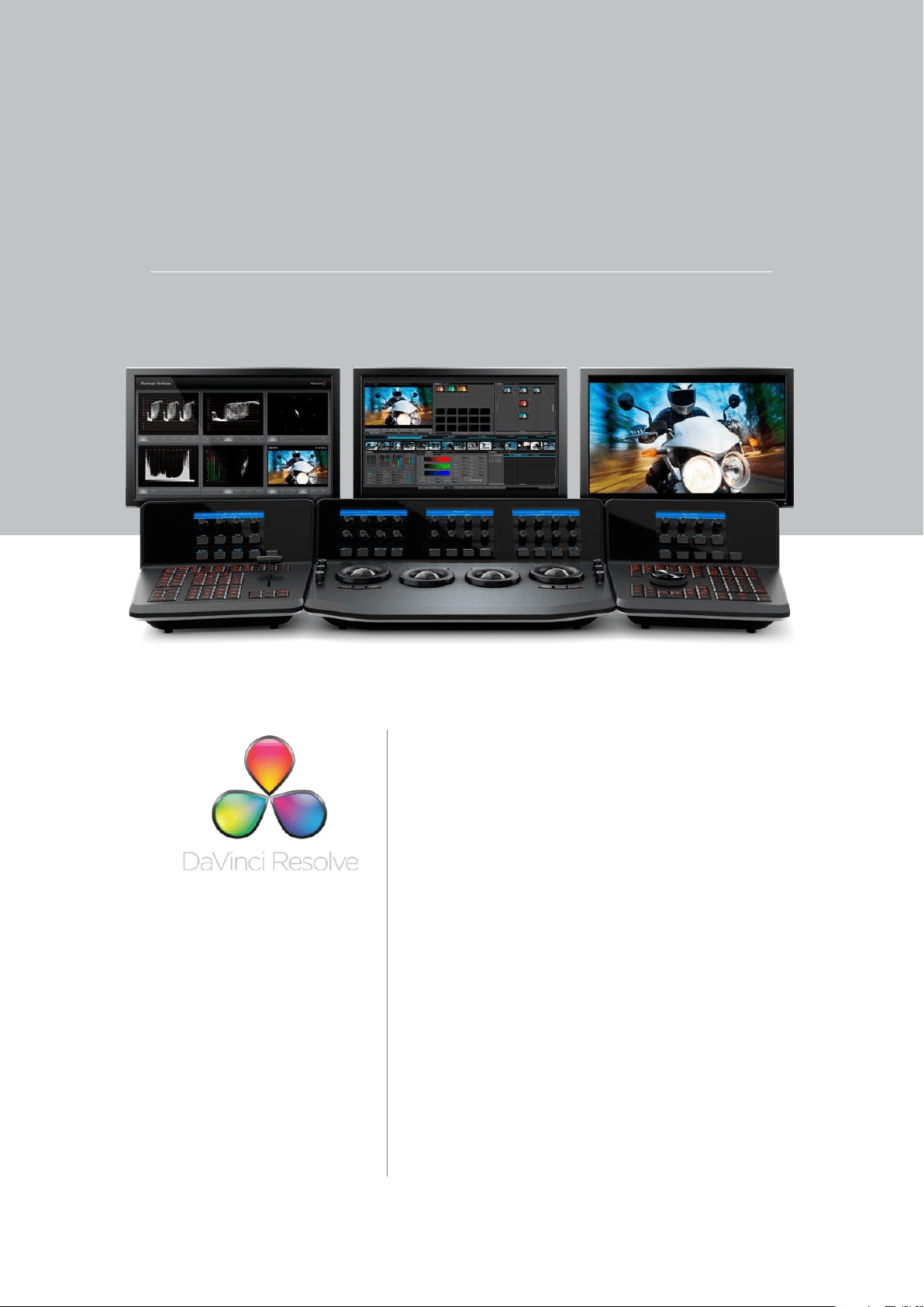
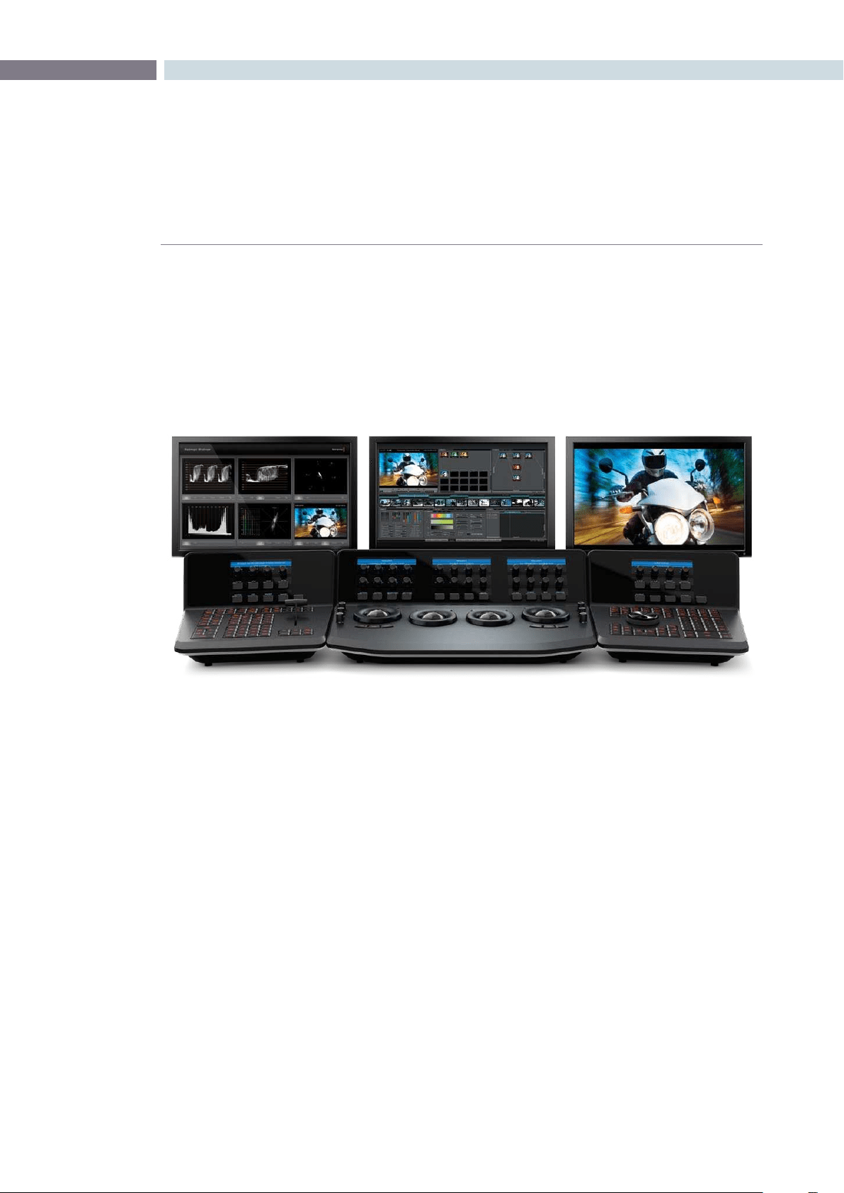
Introducing DaVinci Resolve
Shown with Blackmagic UltraScope

INTRODUCTION 16
Final Cut Pro X XML roundtrip support for frame accurate:
•Cuts
•Dissolves
•Speedchangedevents
•SelectFinalCutProeasysetuptoconguretherendersettings.Afterrenderingthetimeline,
export the Final Cut Pro X XML to complete the round trip.
•EventsnotfullysupportedinFinalCutProXXMLexportarediscardedtopreservetheXML
round trip.
UltraStudio 3D support using ThunderBolt
™
•ProvidesvideomonitoringanddeckI/Ofor2011iMacandMacBookProwithThunderBolt
™
.
•UsesthesamedriverasDesktopVideoforeasierapplicationinterchange
ACES Colorspace support
•ACES/IIFisanewcolorspaceandleformatpromotedbytheAcademyofMotionPictures
Arts and Sciences technology committee to provide a universal and open image interchange
and processing format
•IIFleformatsupport(16-bitoatingpoint.exr)
•UserselectableProjectbasedInputDeviceTransforms
•IncludesclipbyclipsupportintheMediaPoolfor:
•ProjectlevelIDT
•ArriAlexa
•Canon
•RED
•UserselectableProjectbasedOutputDeviceTransformsincluding:
•Rec.709
•DCDM
•P3D60
Support for 3D shaper LUTs
•Controltherangeofyour3DLUTinuencewitha1DLUT
Avid AAF export for simplified Avid AMA round trip
•Supportstimelinerenderwithhandles
•ExportedAAFfromResolveimportsclipsintoMediaComposerbin
What’s New in DaVinci Resolve 8.1

CHAPTER
INTRODUCTION
INTRODUCTION17
1
Avid AAF import support for:
•Diptocolor
•Edgewipewithborder
•Centerwipewithborder
•Clockwipe
•VenetianBlindWipe
•Cross,OvalandDiamondIrisWipe
•SizingEffectwithPTZR
•OverlayComposite
Final Cut Pro 7 XML clip by clip selectable import of image sizing data
•ImportsizingandpositiondataforallorselectedclipstorenderusingthehighqualityResolve
image resizing engine
•Rightclickoncolortimelinethumbnailtoselectsizingforthatindividualclip
Ignore file extension option when conforming using AAF or XML
•Automatically import source clips with either AAF or XML or import with .mov extension and
select .r3d for automatically linking to RED files
•Use low resolution files in editing and conform in Resolve with full resolution files
‘Hover over’ corrector node grading status display to reveal list of changes within the node
•Including:
•Primary
•Saturation,HueandLumMix
•Customcurves
•SoftClips
•Hue,SatandLumCurves
•HSL,RGBandLumSecondaries
•Windows
•Blur,SharpenandMist
•Keycontrol
•Also include indications for:
•Marks
•Tracking

INTRODUCTION 18
Hover node over connector link to auto connect
•Rightclickonthenodegraphtoaddanodeandmoveitoveraconnectorlinkforauto
connection
•+iconindicatesautoconnectisavailable,releasemousetoconnect
HDR source icon in color page timeline thumbnails
•Highdynamicranger3dclipsareindentiedbyanHDRicononthetimelinethumbnail
•Theseclipshaveasecond‘shortexposure’nodegraphinputavailableforusetopermitthefull
HDRx dynamic range to be used
Layer node composite effects
•Offerscoloristsgreatercreativegradingcontrolwith:
•Add
•Subtract
•Difference
•Multiply
•Screen
•Overlay
•Darkerandlighteneffects
Copy and paste node grading metadata between nodes including dynamics
•Makescopyinggradesbetweennodeseasierandfaster
•OnMac,useCommandCandCommandV
•OnLinux,useControlCandControlV
•Ifdestinationclipisshorterthansourceclipthedynamicsareappliedfromtherstframewith
the duration as the destination clip permits
•Alsocopiestrackingmetadata
Clip based Auto/Video/Data level selection
•Automodematchessourcecliporuserselectablescalingtoalternatelevel
•RightclickintheMediaPooltoselectnormallyscaledvideoorfulldatalevelsbycliporgroup
of clips

CHAPTER
INTRODUCTION
INTRODUCTION19
1
Timeline based Auto/Video/Data level render selection
•UsingtheRenderscreenDataLevelpulldownselectthenormallyscaledvideoorfulldatalevel
for rendering clips
•AutomodeselectsformatbasedonselectedleOutputType
Load EDL to new track in existing session
•Ontheconformpage,contextualmenupermitsaddingEDLeventstoanewtracktoaddnewor
changed shots with ease
•Newclipsonhighertrackwillhavegreaterpriorityoverlowertracks
•Deleteoriginalornewclipasrequiredtogeneratenewconformedtimeline
Save EDL of missing clips
•GenerateanEDLofyourmissingclipstouseforselectiveadditiontotheMediaPool
•RightclickonConformtimelinetoselectSaveMissingClipEDL
•UsethisEDLtoAddFolderandSubfolderofnewclips
•Idealforaddingclipsfromadditionfoldersordrivevolumes
Display source timecode option in conform timeline viewer
•Selectthetimecodewithyourmousetotogglebetweensourceandrecordtimecode
•Thetimecodeiconisippedwheninsourcemode
Cut, copy and paste clip keyboard shortcuts in conform timeline
•Selectedclipsintheconformedtimelinecanbecut,copiedandpastedtothesameorother
tracks in the timeline
•OnMac,useCommandX,CommandCandCommandV
•OnLinux,useControlX,ControlCandControlV
•Ifthedestinationclipspaceisshorterthanthesourcetheclipistruncatedtotthedestination
space
•Clipsarepastedstartingfromthetimelinecursor
Additional Pixel Aspect Ratio Option for DVCPRO HD
•SelectableintheMediaPoolwithotherPARoptions

INTRODUCTION 20
Support for Early 2011 MacBook Pro 15” with 1680x1050 display
General performance and stability improvements


2
System Setup
CHAPTER
SYSTEM SETUP
SYSTEM SETUP23
2
DaVinci Resolve on Mac systems require three simple hardware items to be configured when you start
the application for the very first time.
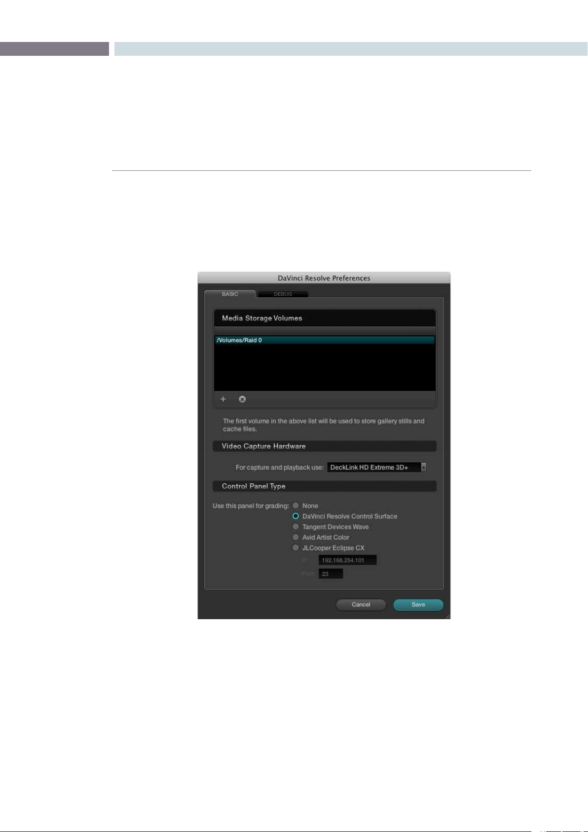
Start the application, select the DaVinci Resolve menu, and choose Preferences. The three items to
establish are: the location of your media images; the video capture card, if any; and the type of control
panel that will be connected to your system, if any.
Media Storage Volumes
IntheMediaStorageVolumeswindowselectthe‘+’(add)buttontoaddavolume,folder,ormount
point to the list of disk storage for your media. The first location in the storage list will become the
default location for images, all proxies, cached files and gallery stills. This location should have plenty of
storage capacity and be permanently connected to your Mac. Often this is the internal RAID you have
established, but it can be an external drive too.
Clickonthe‘-’(remove)buttontoremoveavolume,folderormountpointfromthelistofdiskstorage.
System Setup
DaVinci Resolve Preferences

SYSTEM SETUP 24
Video Capture Hardware
If you have a video capture and playback card, select it from the pulldown list. The options include
supported cards, so if you do not see your card on this list, it has either not been detected by DaVinci
Resolve or it is not currently supported.
Control Panel Type
Finally, select which control panel hardware you have connected to your DaVinci Resolve from the
list provided.
Afteryouhavemadeeachoftheseselectionsselect‘Save’andthenrestarttheDaVinciResolve
application.
Youmayhavenoticeda‘Debug’tab.Thisisusedforengineeringandisnotrequiredforgeneraluse.


3
Quick Start Guide
CHAPTER
QUICK START GUIDE
QUICK START GUIDE27
3
Before getting into the details of grading with DaVinci Resolve let’s have a quick look at each of the
main application screens and their functions.
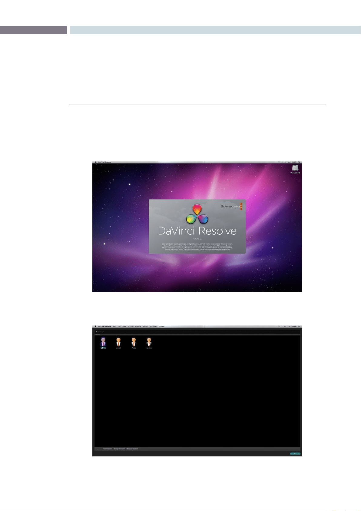
When you start DaVinci Resolve the launch window opens and each software module reports its
loading status.
When the start-up is complete the User Login screen appears. Double click on a User icon to switch to
the Configuration screen for that user.
Mac Start-Up
User Login
Quick Start Guide
QUICK START GUIDE 28
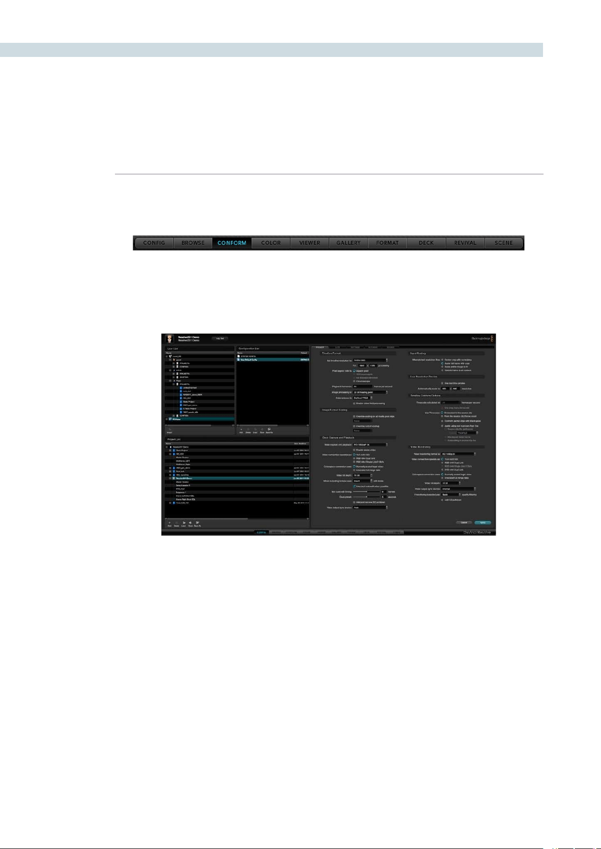
After you login to Resolve, this navigation bar appears at the bottom of every main screen. Use a left
mouse click on this bar to switch to each screen.
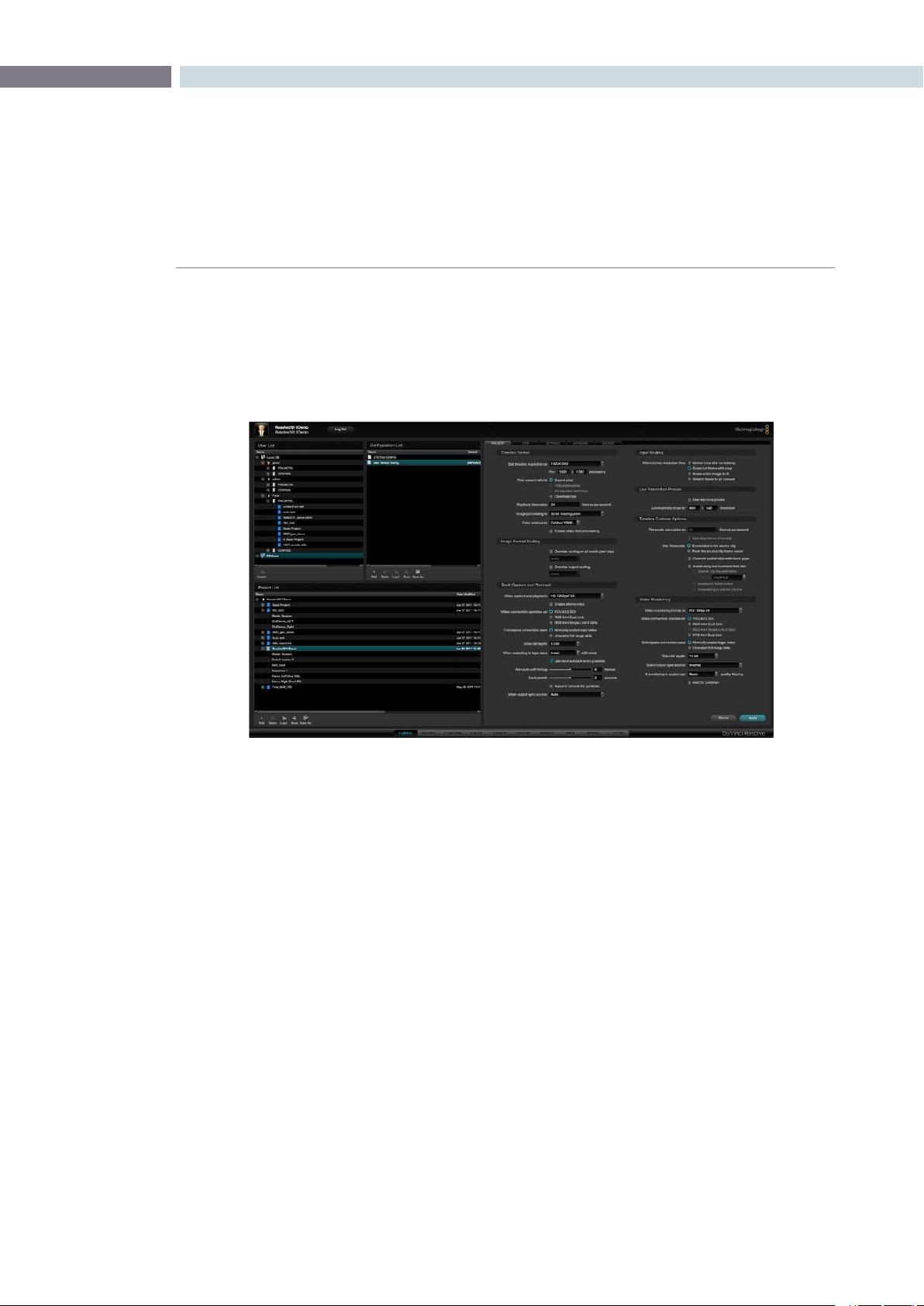
The Configuration screen shown below is used to configure projects based on the user. With the five
tabs located on the right half of this screen you can set up new projects, load existing projects, and
select the format and connection type for deck capture and playback.
Configuration Screen
Navigation Bar
CHAPTER
QUICK START GUIDE
QUICK START GUIDE29
3
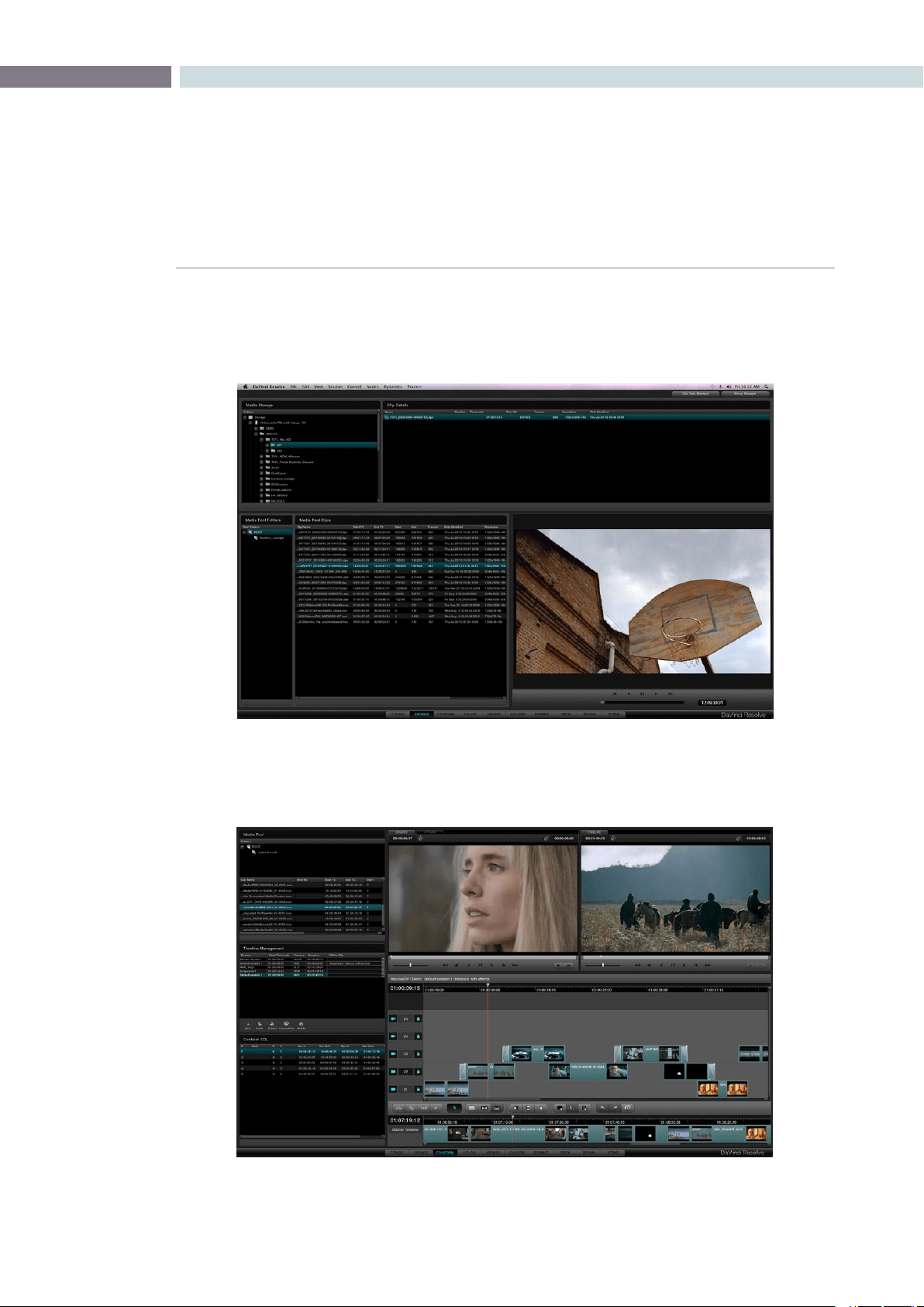
Use the Browse screen shown below to select and review clips that are in your media storage and to mark
the individual clips you need for your project. On the Browse screen you can create a Master timeline, load
your EDLs and compare the hi-res source clips to your offline video from the edit system.
The Conform screen is used to establish your Master Session/ timeline, organize clips into a numbered
order designated by an edit decision list and to confirm the edit via an offline video.
Conform
Browse
QUICK START GUIDE 30
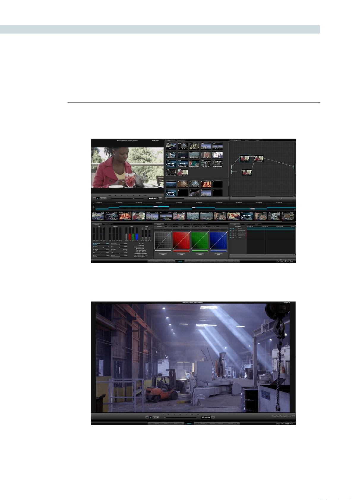
Most of your grading time will be spent here, at the Color screen. This includes a viewer, gallery of stills, a
project and clip timeline and all the tools you need to create a master grade.
The Viewer screen provides a full screen view of your images with transport controls, and controls for the
automatic image object tracker.
Color
Viewer
CHAPTER
QUICK START GUIDE
QUICK START GUIDE31
3
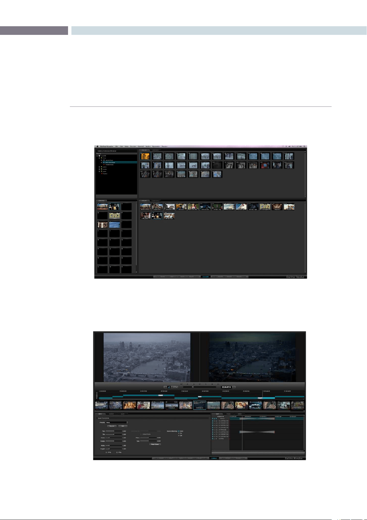
When you capture or import stills, they are all displayed in the Gallery screen. Here you can move them
between different folders and name them as you like.
The DaVinci Resolve Format screen interface makes it simple to format an image. You can adjust input
and output image formats and size, pan and tilt the image, even zoom and rotate, all while seeing your
changes in the viewer in real time.
Format
Gallery
QUICK START GUIDE 32
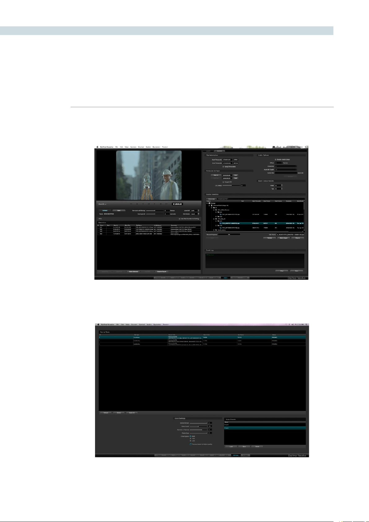
Ingest from, or record to videotape all your SD and HD images using the Deck screen. There is also a
batch capture option to speed up those otherwise cumbersome ingests from a long list of clips.
If your DaVinci Resolve is connected to a DaVinci Revival image restoration system you can use the
Revival screen shown below to manage interaction between the systems.
Deck
Revival
CHAPTER
QUICK START GUIDE
QUICK START GUIDE33
3
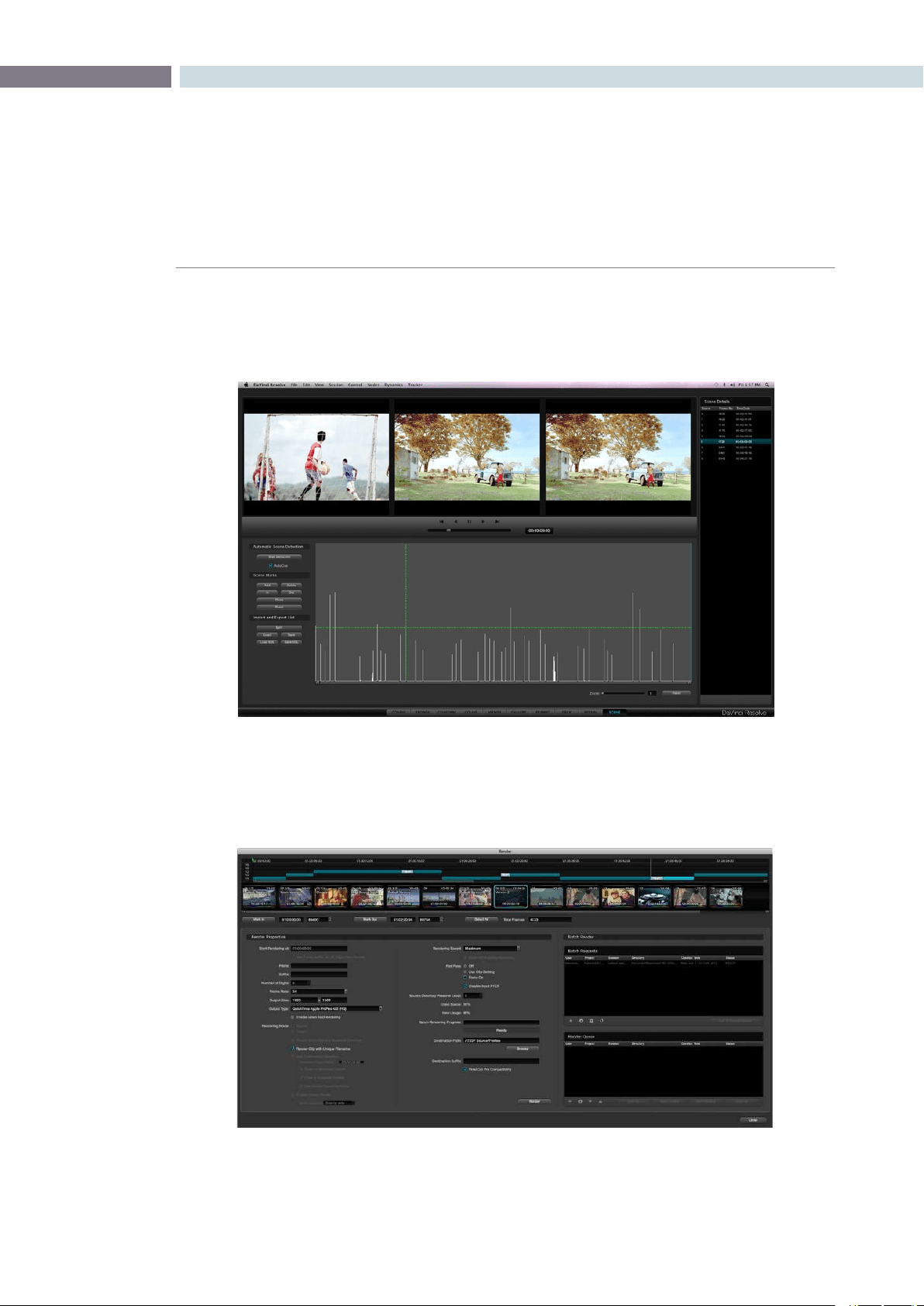
Sometimes you have images to grade but no EDL to split them into clips. No problem; just use the
Scene Cut Detector to find those scene cut points automatically and split the source clip. It works five
times faster than real time so you can start grading faster.
The Render screen is used to set up the configuration and initiate rendering of the timeline images.
Many systems limit the render of clips to the settings used in the timeline. Resolve is not restricted by
this limitation and this provides you with significant workflow advantages unmatched in the industry.
Render
Scene Cut

QUICK START GUIDE 34
Quick Start Project
This Quick Start overview is designed to skip past much of the detail and get you quickly to the Color
screen so you can learn how to login, configure and load a project, select clips, create a master timeline
and start grading. Once you have these basics understood, you can continue learning the details of
DaVinci Resolve operation as you reference each of the chapters in this User Manual.
Assuming you have installed the DaVinci Resolve application and used the Preferences menu, as
detailed in Chapter 2, to set up your media storage, video capture hardware, and control panel type, the
final preparation step is to put some images on your media storage drives.
OntheDaVinciResolveapplicationDVDthereisafoldercalled‘SampleImages.’UseMacFinderoryour
Linux Browser to copy this folder and contents to your media storage.
1. Start DaVinci Resolve. At the Login screen double click on the Guest icon.
2.TheCongurationscreenwillautomaticallyopenafterthelogin.Selectthe‘Add’button
on the bottom left of the screen in the Project List display. In the window enter the new
projectname,‘SampleProject’and’Save.’
3. Using the navigation buttons, select the Browse screen and look for your media
storage at the top left. Expand the folder view, if necessary, and select the folder
‘SampleImages’thatyoucopiedfromtheDVD.Nowrightclickonthefolderandselect
theseconditemintheoptionslist,‘AddFolderIntoMediaPool.’YouwillseetheMedia
Pool populated with a few files.
4. Select the Conform navigation button and, on the left in the Timeline Management
display,select‘New’andconrm‘OK.’AtthebottomyouwillseetheEDLdisplaylist
the events, which will show as clips on the Master Session timeline.
5. You are ready to switch to the Color screen. The timeline will be populated and the
Viewer will show the first frame of the first clip. You can jump to clips by selecting them
on the Thumbnail Timeline or use the transport controls under the Viewer.
6. Within the Primary tab, click and drag the red, green or blue slider within the Lift,
Gamma, or Gain display. To the left of these is the Luminance Gain. Click and drag the
Luminance Lift a little lower and the Luminance Gain a little higher.
7. To add a PowerWindow, click on the Windows tab and select the circular window, turn
it on, and note the window cursors on the Viewer. Select a cyan anchor point and click
and drag to change the size or aspect. Now adjust the primary controls or curves and
note that the grade you apply is inside the window.
Follow the rest of this User Manual to learn the full power of DaVinci Resolve.


4
Control Panels
CHAPTER
CONTROL PANELS
CONTROL PANELS37
4
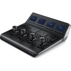
While DaVinci Resolve can be operated with a mouse and keyboard, the full creative power of the
system is unleashed when used with the DaVinci Resolve Control Surface.
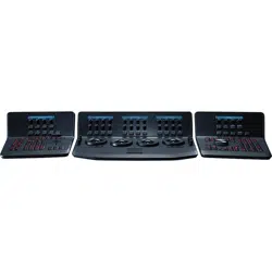
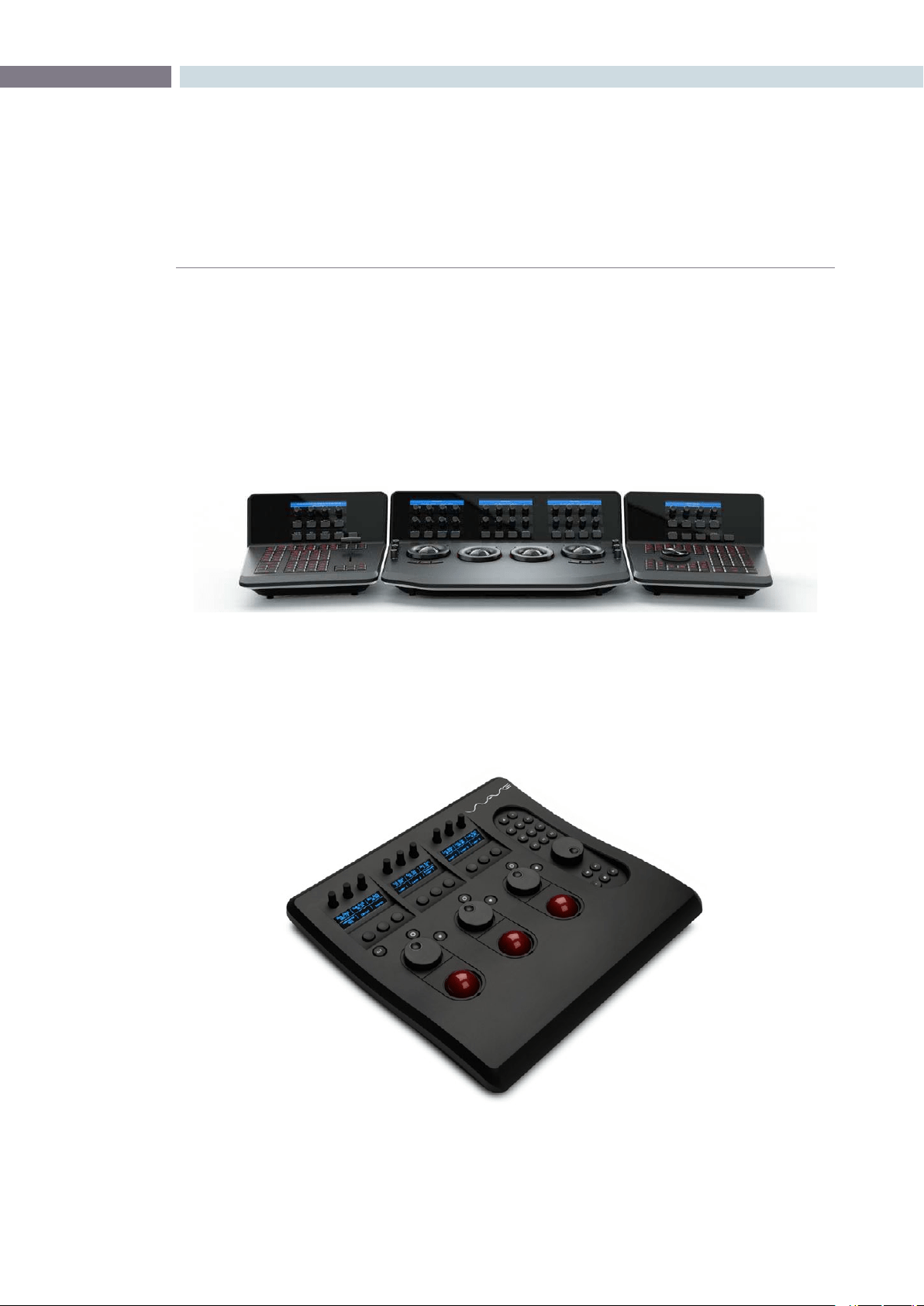
The DaVinci Resolve Control Surface consists of three panels. The center Trackball panel is used for
most grading operations and includes a slide-out keyboard and trackballs. The two side panels are
interchangeable for left- and right-handed operation. The Transport panel includes a jog/shuttle control
and is often placed on the right (for right-handed colorists) with the T-bar panel on the left. The panels
are usually located some distance from the Resolve workstation, however it is very simple to connect
them together with a USB2.0 cable.
Details of the panel operation and menus are found later in this guide.
DaVinciResolvealsosupportstheAvidArtistColor,TangentDevices‘Wave’andtheJLCooper‘Eclipse
CX’ panels. These panels offer significantly improved creative control compared to using a mouse,
however there are a number of features offered with the DaVinci Resolve Control Surface that are not
possible on the third party panels.
Control Panels
Tangent Devices Wave

CONTROL PANELS 38


5
Getting Started
CHAPTER
GETTING STARTED
GETTING STARTED41
5
Starting DaVinci Resolve
Click the DaVinci Resolve icon to start the application. As the system is starting the launch window
opens and each of the software modules reports its loading status. When the start-up is complete the
UserLoginscreenwillappear.YoucancloseDaVinciResolveusingthe‘Exit’button,whichisonthe
User Login/Exit page.
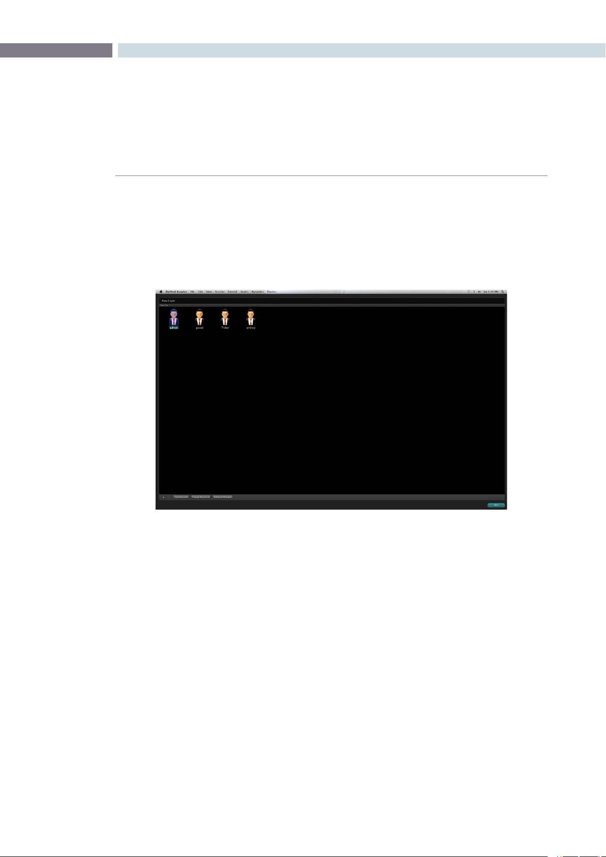
User Login Screen
DaVinci Resolve uses a database to store grading information for each project and each user. Each
user’s file contains stored color corrections and system configurations for your projects.
Login To An Existing User
The User Login screen displays an icon for Admin, Guest, and all other users. To login without a password,
simply double click on the Guest icon. If you double click a password protected user, just enter the
password and continue. If needed, easily create a new user as indicated below. As all projects require
pre-configuration prior to grading, once the login is successful, DaVinci Resolve will automatically switch
to the Configuration screen.
Exiting Resolve
When you have completed your work, save the project, use the log out button on the Configuration
screen and then Exit on the User screen.
Getting Started
Colorist Login
GETTING STARTED 42
Creating A New User
TosetupanewuserselecttheAdminiconandthenthe+buttononthebottomleftofthescreen..
The administrator can use password protection to lockout the New User function. When DaVinci Resolve
is first installed the Admin password is left blank. If the Administrator has protected the operation with
a password please see your Admin to gain access.
You may also change the graphic for each user by right mouse clicking on the icon and selecting
‘ChangePicture’.
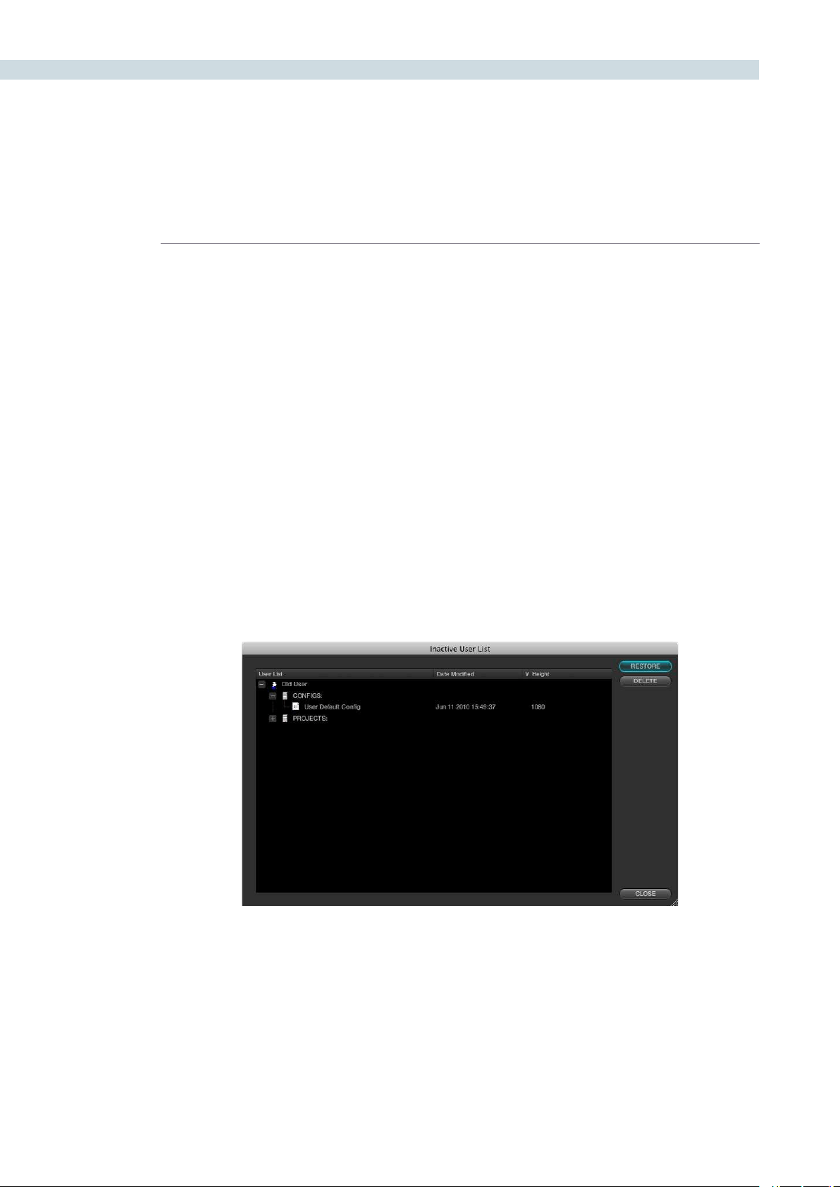
Deleting An Existing User
To delete a user select the user’s icon and then the - button at the bottom of the screen. Confirm the
Admin password and then a prompt will appear asking you to confirm the user deletion. Don’t worry if
you have done this accidentally as DaVinci Resolve stores the old user information in an Inactive User
file so you can recall the data whenever you need to.
Byclickingonthe‘InactiveUsers’buttonatthebottomoftheLoginscreen(youmusthaveAdmin
privileges), the Inactive User List will appear and allow you to either reactivate or permanently delete
the users listed.
This permanent deletion of the user is final! Be sure you really want to delete the user and their projects,
stills, configurations, etc.
Inactive Users List
CHAPTER
GETTING STARTED
GETTING STARTED43
5
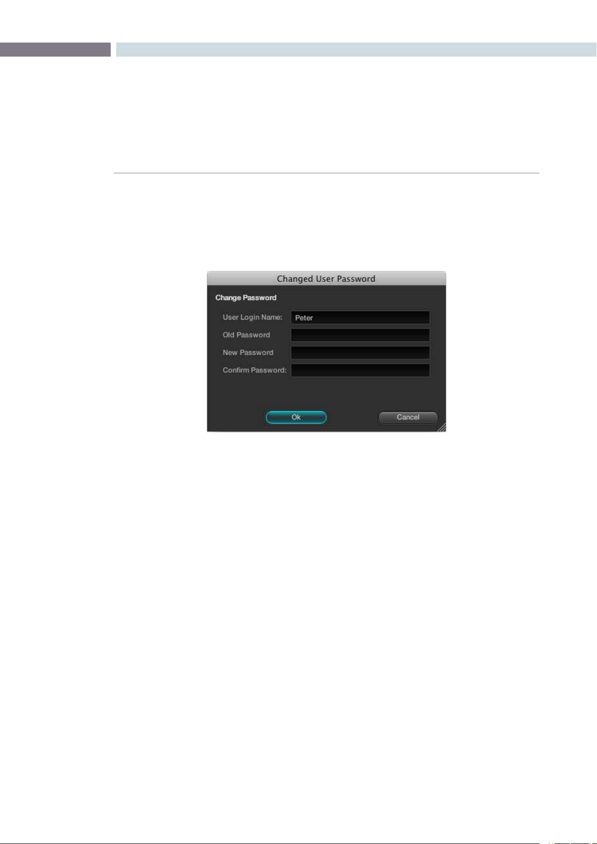
Changing A User Password
Change your user password by simply selecting your User Icon to make it active and then the
‘ChangePassword’button.IntheChangedUserPasswordwindowenteryouroldandnewpasswords
and confirm.
Multiple Database Support
DaVinci Resolve works from an internal database server so it’s possible to have multiple databases for
maximum flexibility in organizing your projects. You can create a database for each year, or whatever
timeframe you desire. Keeping the database size small makes loading and saving faster.
Facilities with multiple systems can implement a shared Remote Database Server.
Selecting the Database
You don’t need to do or know anything about databases to use DaVinci Resolve. It’s all set up for you
when you install the software.
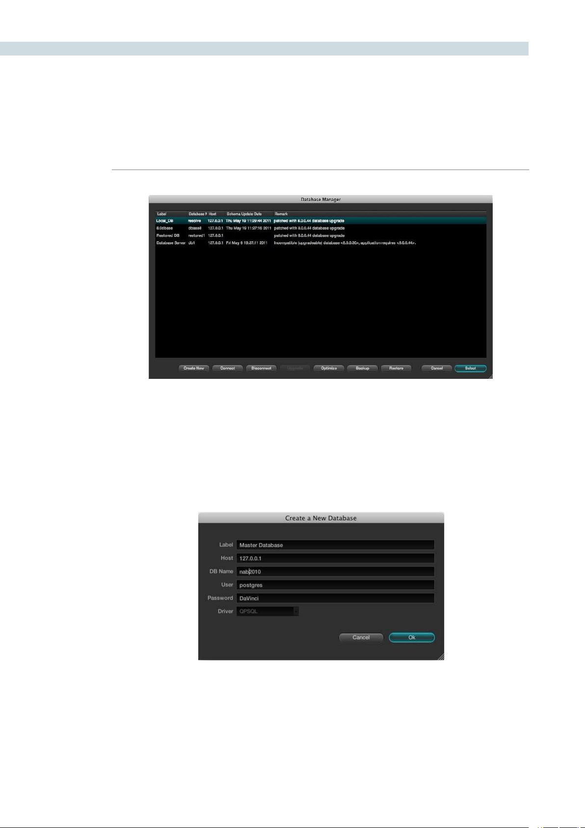
Tomakeadatabaseyouractiveworkingdatabase,clickthe‘DatabaseManager’buttonontheLogin
screen. Select a database from the list and confirm with the Select button. This database will now
be used for saving all new projects. The other databases that are connected, the internal and also
remote databases, will continue to appear in the list and you can import projects from those databases.
However when you save a project, regardless of its origin, it will save into the active working database
you selected.
Change User Password
GETTING STARTED 44
Creating a New Database
OntheDatabaseManagerwindowselect‘CreateNew’tocreateandaddanewdatabasetoyouravailable
database list. Enter a label name to help identify the database in DaVinci Resolve and a unique database name,
in lower case. If you are using the database on this workstation leave the other items unchanged and confirm
OK. This new database is now available and you can add your user as detailed above. All of the old projects are
still available. How to import them is found later in this guide.
Database Manager
New Database Popup

CHAPTER
GETTING STARTED
GETTING STARTED45
5
Create a New Database Image
If you are connecting to a Remote Database Server, change the IP address from the local machine address, which
weshowasdefaulttoyourRemoteDatabaseServer.Entertheremotedatabasenameandselect‘postgres’
forallnewdatabaseswithfullread/writeaccessor‘MySQL’forreadonlyaccesstolegacyDaVincidatabases.
Remote Database Server
Multiple DaVinci Resolve systems can also work on the same project at the same time using the shared
database. For example an assistant could be working with the colorist to prepare files for the next reel
by conforming shots, managing the VFX replacements or using the system to do dust busting repairs,
etc. Resolve automatically prevents two users working on the exact same item by opening a copy of a
project if one is already in use and will advise you when the other session is closed.
We highly recommend the use of a separate workstation to operate as the Remote Database Server for
facilitieswithmorethantwoDaVinciResolvesystems.Byselecting‘Connect’intheDatabaseManager
youcanentertheinformationrelatingtotheremotedatabase.JustllineachitemandconrmOK
Optimizing a Database
If the database in Resolve becomes too large you may need to optimize it to improved the access speeds.
Simplyselectthe‘Optimize’buttonandthedatabasewillvacumnedofunrequiredspacesandreindexed.
Backing Up a Database
You can at any time back up and restore a database. This provides added protection should your database hard
drivefailorcanbeusedtomovemultipleprojectsbetweensystems.Selecting‘Backup’willopenthender
window and you can define the file name and location to backup. Be sure not to change the .backup extention.
Restoring a Database
If you have previously backed up a database, or have one from another system you can restore this database
over the orginal or create a new empty database to restore too. Select the destination database and then click
‘Restore’.Navigateusingtheopenndertothedatabaseyouwishtorestoreandselect‘Open’.Youthenneed
to confirm to overwrite the database you selected as the destination and the database will be restored.

GETTING STARTED 46


6
Configuration
CHAPTER
CONFIGURATION
CONFIGURATION49
6
At the commencement of every project a number of user, project, deck and monitor configurations
should be set to provide the correct environment for your color-grading project. You can open the
default or an existing project and/or may change the various settings to accommodate the project
needs. You can also assign a name to the project. These tasks are performed on the Configuration
screen which is the first screen always opened by DaVinci Resolve after you log in.
At the commencement of every project a number of user, project and operational configurations
should be set to provide the correct environment for your color-grading project. You can open the
default or an existing project and/or may change the various parameters of the configuration in order
to accommodate the project needs. You can also assign a name to the project within this page. These
tasks are performed on the configuration screen which is the first screen always opened by Resolve.
Configuration
Configuration
CONFIGURATION 50
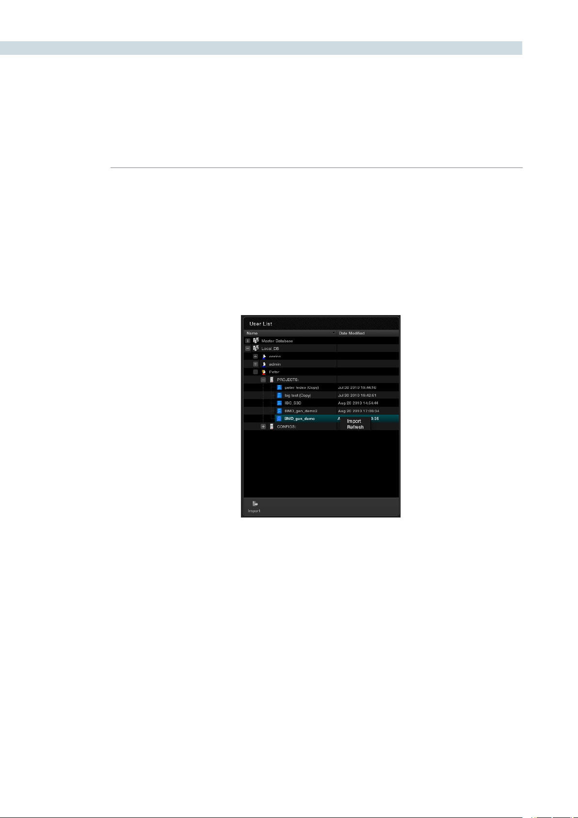
The User List
This screen lists all available databases with the users and their associated projects and system
configuration files. Note that you will not see your user ID within the current database. This list allows you
to simply import projects from other database or from other users into the current database and user.
Expandthelisttondandselecttheprojectorcongurationandselectthe‘Import’button.DaVinci
Resolve will import that project or configuration and place it in your active database.
User List
CHAPTER
CONFIGURATION
CONFIGURATION51
6
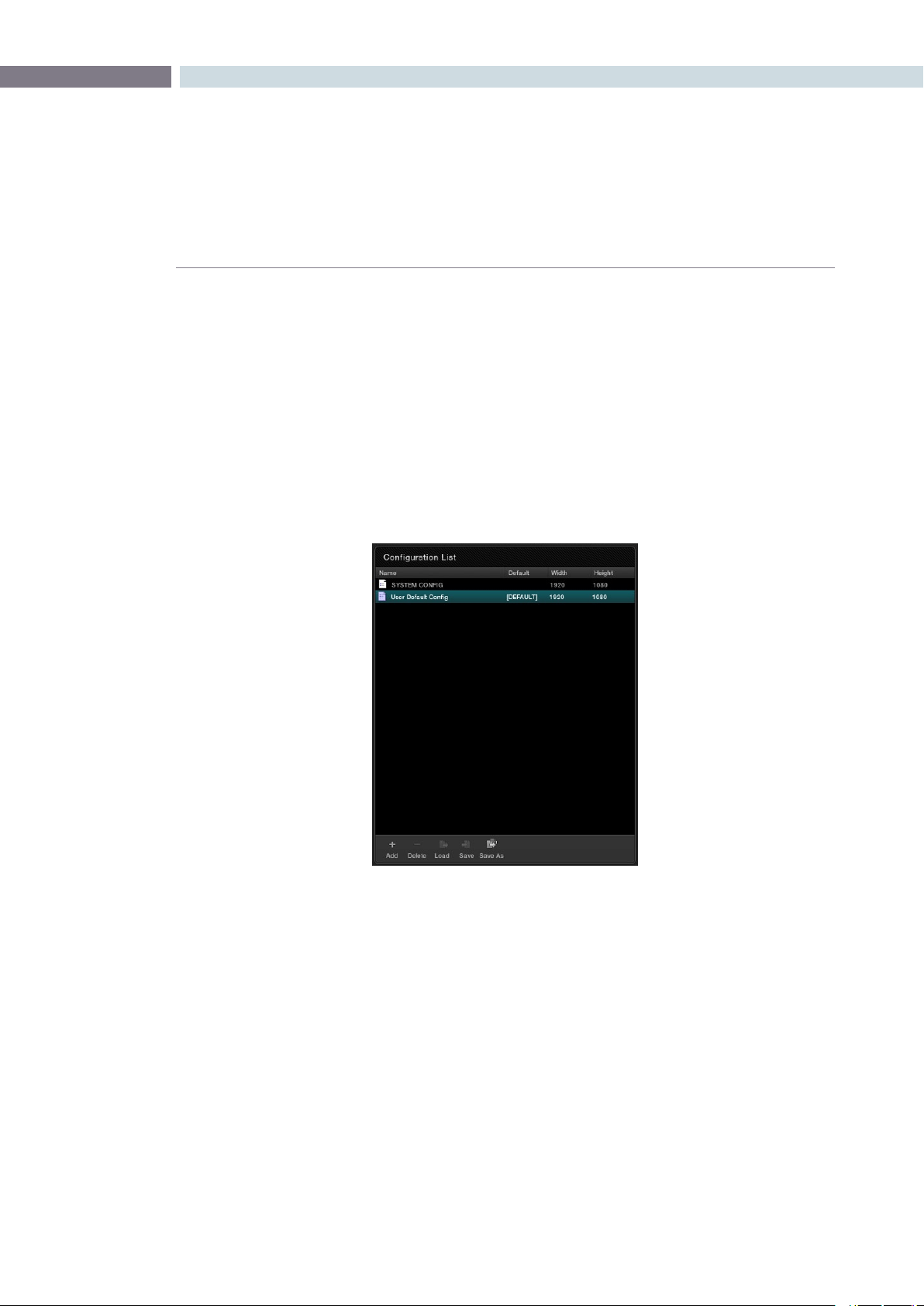
The Configuration List
The Configuration List will show all configurations saved within the current database for the current user.
As the Admin you can define a User Default Config that can be used as a default system configuration
for all new projects.
Modifying and Saving an Existing Configuration
To modify an existing configuration, highlight the configuration and make the changes, or modify the
project configuration. Save these settings to the configuration or cancel to revert to the original.
Further details on the Configuration screen tabs and their operation follow later in this section of the guide.
Within the Configuration List window you can:
Add: This allows you add a new config with the current settings.
Delete: To delete an existing config, select the config with your mouse and then the
‘Delete’button.
Load: This will load the selected configuration file.
Save: Any changes that have been made into the existing (i.e., highlighted)
configuration file are saved.
Save As: To save configurations with an alternate name and thus create a new
configuration file use Save As.
Configuration List
CONFIGURATION 52
Creating a Facility Default Configuration
There are two default configurations in DaVinci Resolve: a User Default and a System Configuration.
To modify a System Configuration and save it as the default configuration for all new users, first login
asAdmin,thenselect‘SystemCong’withintheCongurationList,makethechangestotheproject
andusercongurationsandselect‘Save’.Allnewusersthatareaddedtothesystemwillautomatically
inherit these User default settings which can then be modified by the individual users and saved on a
per project or configuration basis.
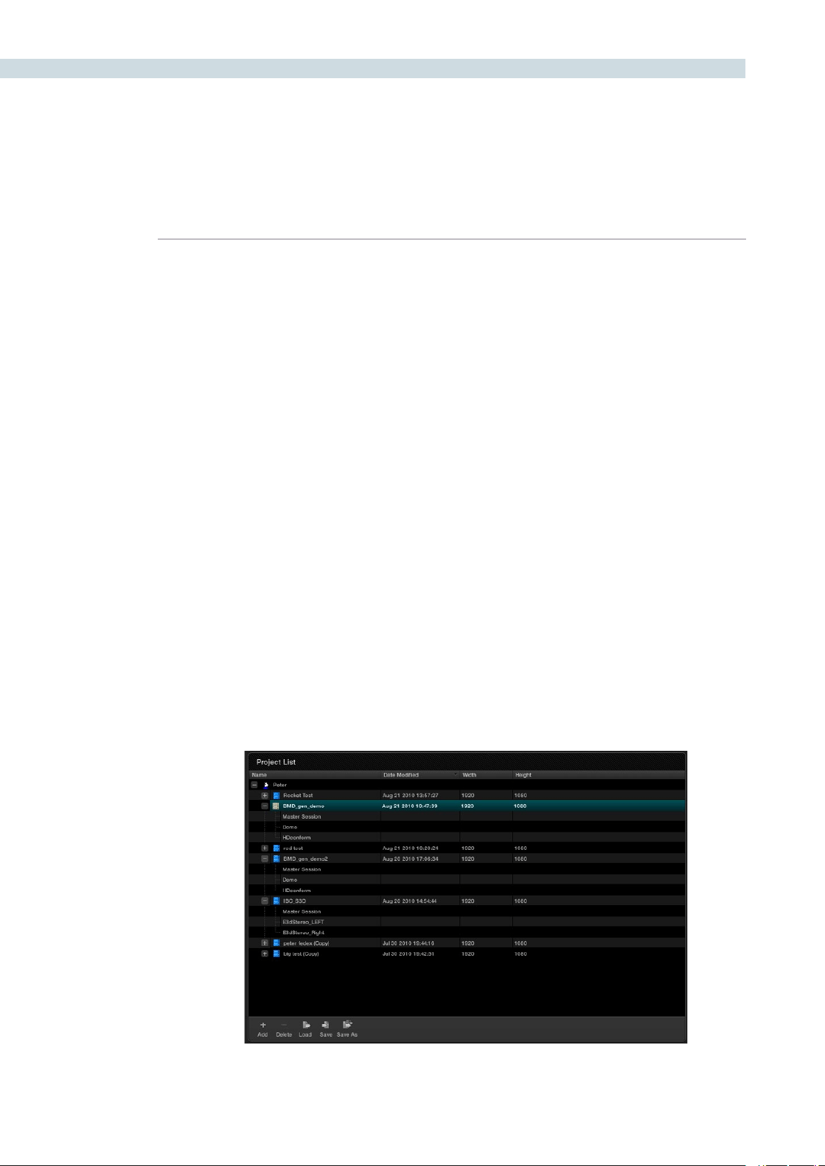
Projects List
TheloggedinuserhasaProjectListtoshowallprojectsassociatedwiththatuser.Clickingonthe’+’
located to the left of the User ID will reveal the projects associated with that user. It also shows the date
onwhichtheprojectwasmodiedandtheprojectresolution.Byselectingthe’+’thatislocatedtothe
left of the project name, the project file and any associated sessions (EDLs) are also revealed.
There are a number of user controls in this window.
Add: Create new project.
Delete: When you select a project, then delete, that project will be deleted from the
database. Please be sure you wish to delete the project.
Load: The selected project in the project list will be loaded.
Save: Any changes that have been made into the selected project file are saved.
Save As: To save a project with an alternate name and thus create a new project file use
Save As.
Project List
CHAPTER
CONFIGURATION
CONFIGURATION53
6
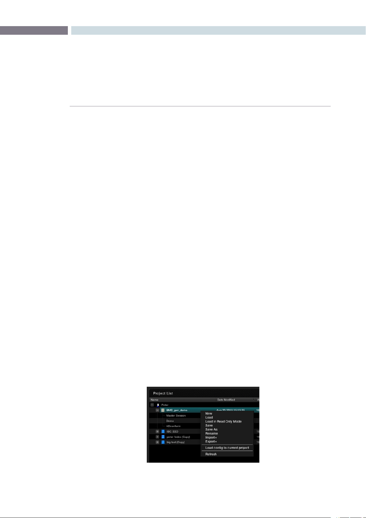
There are also a number of features available via a right mouse click within the Project window. If you
select a project and right click the pop-up display will provide the following options, depending on the
status of the current project.
New: Opens a window to create a new project name for the new
project.
Load: Will recall the project configuration and sessions, but only after
checking if the current project has been saved. If it has not
been saved, it will give you that option.
Load in Read Only Mode: Like Load, this will recall the project and load it into the system.
This feature is used for loading a locked project when in a
shared database environment. You are not permitted to save
any changes to the project in this mode.
Save As: You can save a project with a new name. Often ideal for
creating multiple versions of projects or versions for export.
Delete: Allows you to delete a project.
Rename: Use this to rename an existing project.
Import +: DaVinci Resolve allows you to Import and Export projects and
will package all the project metadata, EDLs, LUTs and audio
material into a compressed file which may be easily imported
or exported between systems. If the project images are not
on a shared SAN, you must manually manage the required
images.UseImport+tobringprojectsintothisdatabase.
Export +: If you wish to create a backup of this project with the grading
metadata,orexportitforuseelsewhereuseExport+.
Load config to current project: Uses the configuration selected in the configuration list to
replace the current project’s configuration. A simple way to
make sure your project uses the correct settings.
Refresh: To refresh the display simply right click and select Refresh.
Project List Options (Right Click)
CONFIGURATION 54
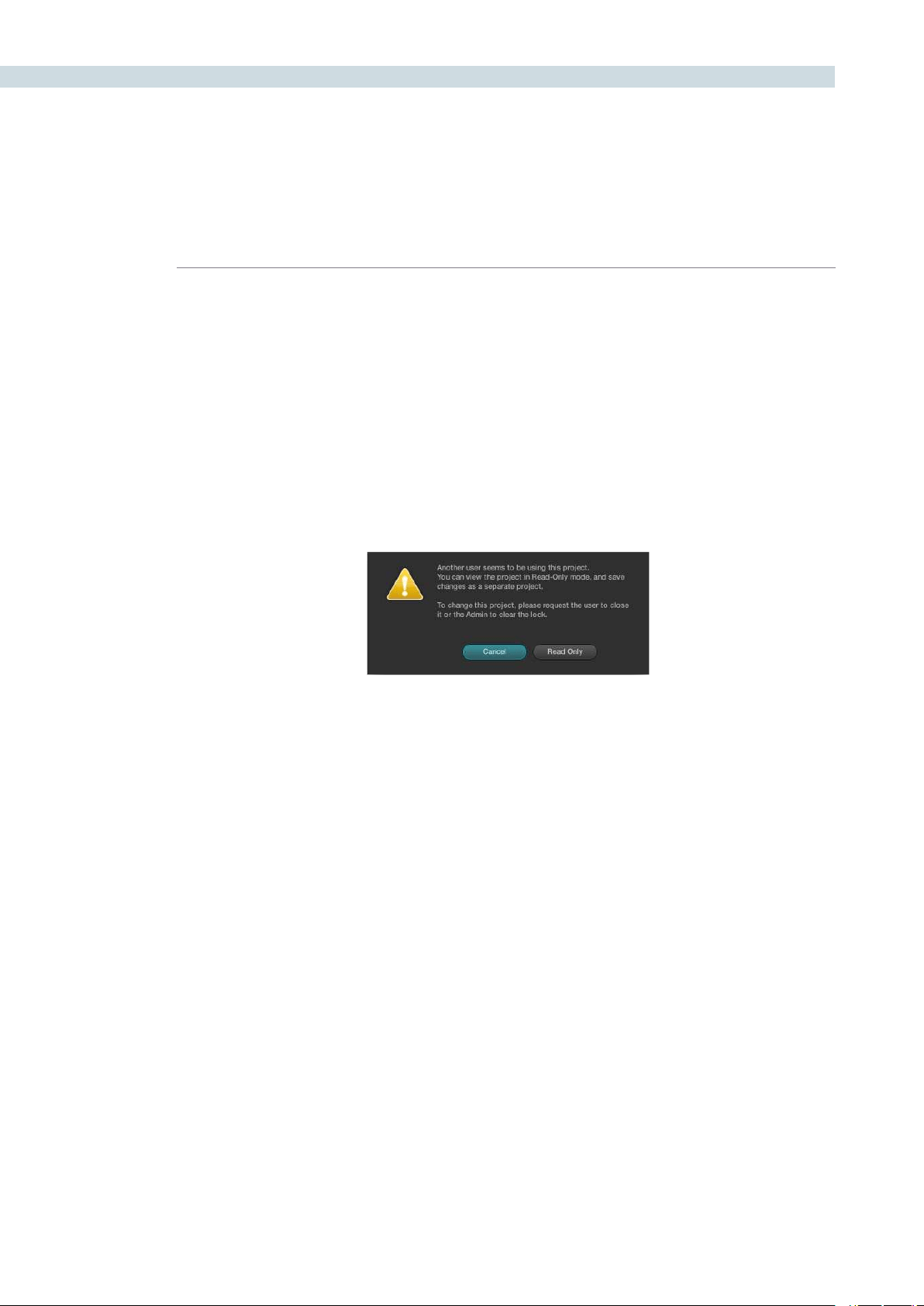
Shared Database and Locked Projects
If you are using a shared database with other DaVinci Resolve systems some of the projects will have
a lock icon to the left of the project name. A locked project is loaded in read-only mode and changes
must be saved to a new file name. Once a shared project is loaded, it is automatically locked in order
to prevent multiple users from accessing the project at the same time. To unlock the project, login as
Adminandthenclickonthe‘Unlock’button.
For large projects that are being worked on in parallel, often the project is split into logical segments
so users can work simultaneously in different suites. For example, a feature film may be split into reels,
or the film separated from the trailer and video press kit. Each segment can use grades from the other
segments as required to keep the shots in balance.
Read-Only Confirmation Dialog
CHAPTER
CONFIGURATION
CONFIGURATION55
6
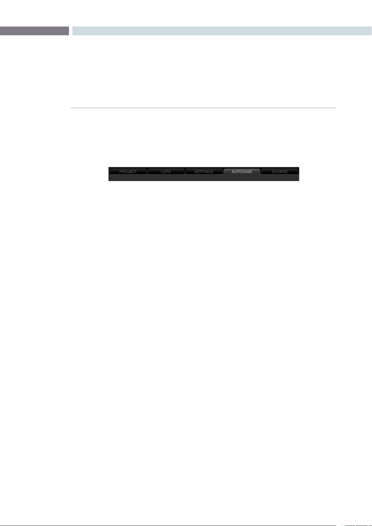
Configuration Screen Tabs
Using the five tabs on the Config screen you can make changes to the configuration to suit your project
orles.Ineachcase,the‘Apply’and‘Cancel’buttonslocatedatthebottomofthetabssaveorcancel
any changes made.
The tabs are:
Project: Provides the main configuration settings for DaVinci Resolve to process your
images. The first step in setting up the configuration for any project is to determine
which resolution you will use. You may also choose to change the standard for
monitoring as well as Deck standards for importing and exporting material.
LUT’s: Select, trim and generate look up tables and define where they are used.
Settings: Selections for many user and project variables, including the default dynamic
profile and automatic dynamic ripple features, are made in the Settings tab.
Autosave: Displays the auto project backup information.
Source: While DaVinci Resolve’s default file format is the SMPTE standard dpx file, many
other formats are processed natively within Resolve. This tab provides system based
configuration and adjustments for the RED camera r3d files.
Other formats will be added in the future.
Config page tabs
CONFIGURATION 56
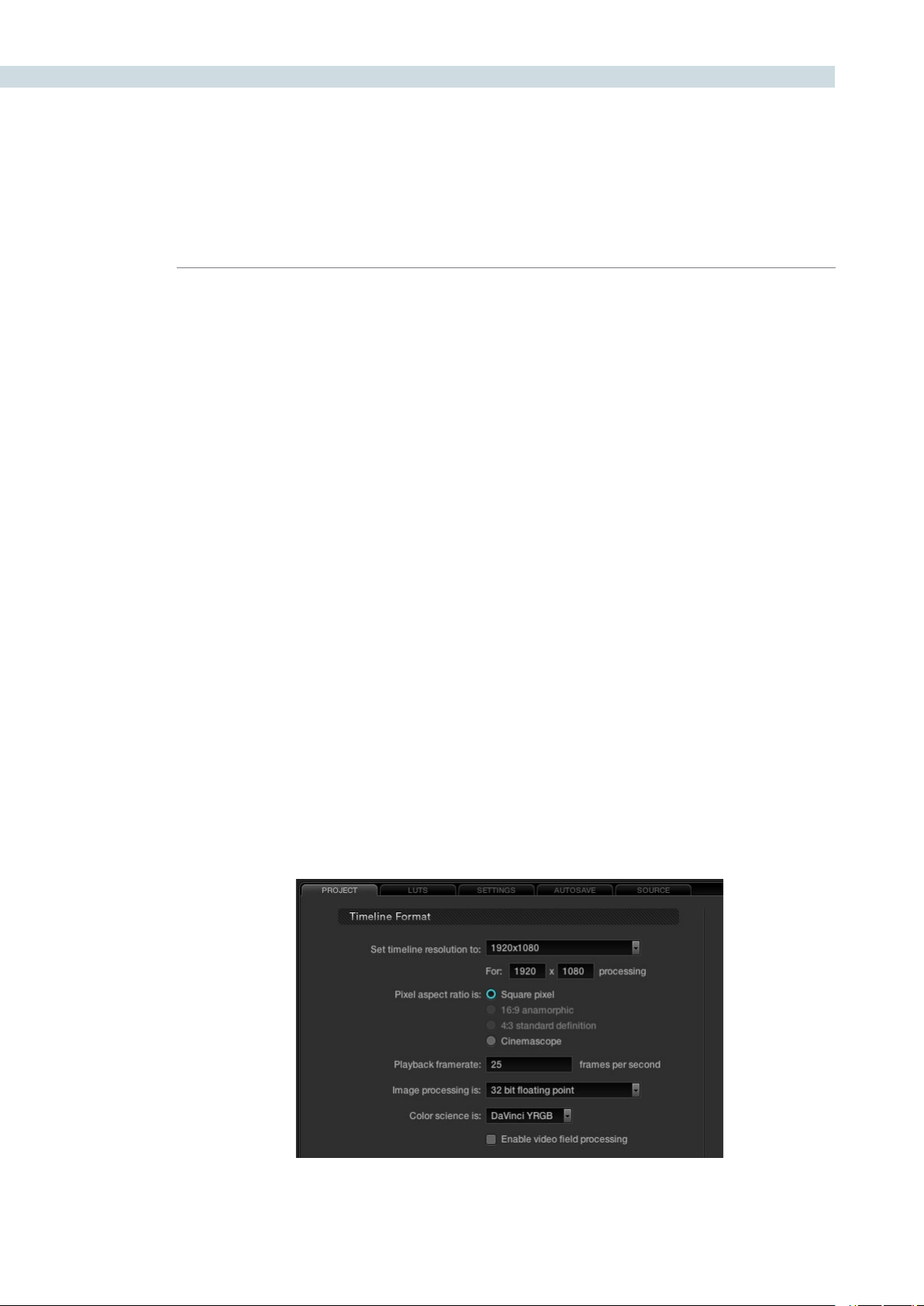
Timeline Format
The Timeline Format section defines the parameters used for image processing during grading.
For example, if you use a HD grading monitor, setting the system resolution to 1920x1080 provides
automatic up or down sampling of the source images on the grading display. When you render the
files, the render resolution can be set to any other parameter so this system resolution is just to set the
working specification for the system while grading and it does not limit the settings for deliverables.
You can customize the timeline format settings or use the templates provided. The controls are:
Timeline Resolution selects from a preset list and then displays the resolution selected for image
processing while grading. You can change the setting for resolutions not found in the presets. The
Pixel Aspect Ratio is used to select other than the normal square pixel format. You can apply a 16:9
anamorphic pixel aspect, a 4:3 for SD images or Cinemascope ratio.
Playback framerate is often based on the setting of the grading monitor so a 50Hz monitor will need
a 25 fps playback speed for a synchronous display without dropping frames. If you want to see the
playback at a slower rate set it here and DaVinci Resolve will make the appropriate calculations and
drop or repeat frames as necessary. This can be handy to see how images look in slow motion.
DaVinci Resolve uses 32 bit floating point processing for all grading calculations and this currently is the
only option available as is the legendary and unique DaVinci YRGB color science.
Resolve is a frame based system but it can process interlace video material. If your source format and
record format are the same, for example HD in and HD out, you may use Resolve in its native frame
based configuration, even for projects that have 100% interlace material. If however you use the image
resizing engine to change the image size, including resize a HD to SD image, or to make significant
imagesharpeningorblurprocessingyoumaywishto‘Enablevideoeldprocessing’.Resolvesinterlace
image processing consumes significantly more GPU power to maintain the high picture quality so
enabling this checkbox will result in a slower playback speed or a reduced number of nodes at real time.
Project Tab
Project Tab
CHAPTER
CONFIGURATION
CONFIGURATION57
6
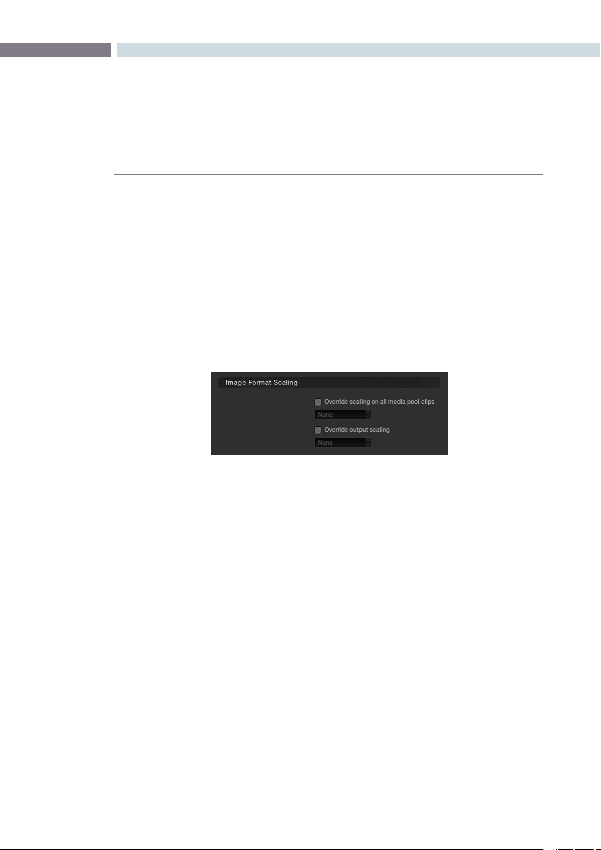
Image Format Scaling
You can set Input and Output Format Presets that can be used with session clips or for a complete
timeline. These presets may be applied as Global presets from the Configuration screen or a Clip preset
within the Media Pool which you will find on the Browse screen. Presets may also be applied from within
the Format screen or even by right mouse clicking on a thumbnail within the Color or Format screens.
There are more details on presets later in this guide.
These user-defined presets are settings for various image sizes and are very useful, for example, when
a film has been over scanned. Instead of having to resize every clip independently you can resize a
clipandusethepresettoapplytoall.Ifyouselect‘None,’thiswillindicatethatnosettingshavebeen
applied.Withinthe‘ImageFormatScaling’selections,ifthecheckboxesareactivatednexttoeach
option, the programmed settings will be overwritten with the newly selected presets.
Format Preset Selection
CONFIGURATION 58
Common use of Input Format Preset
If your project originated on film it will have been scanned at some time prior to editing and grading, and
often to make sure all the image area is captured the image is slightly over-scanned. This means you will
see the full open gate image and depending on the scanner, some of the edges around the image, or
even sometimes the round corners or distortion in the corners of the image.
To avoid the time prohibitive process of manually resizing every shot so that it matches every other,
simply create a resize of a reference image. Save this new image size as an Input Format Preset and
select this preset. The optical quality zoom and positioning controls will produce outstanding results,
on the fly, so you don’t need to pre-render and you can always make further adjustments during your
grading session. To create an Image Format Preset, simply make a size change with the formatter on the
Formatscreen,clickonthe‘SaveAs’button,enterapresetname,andsave.
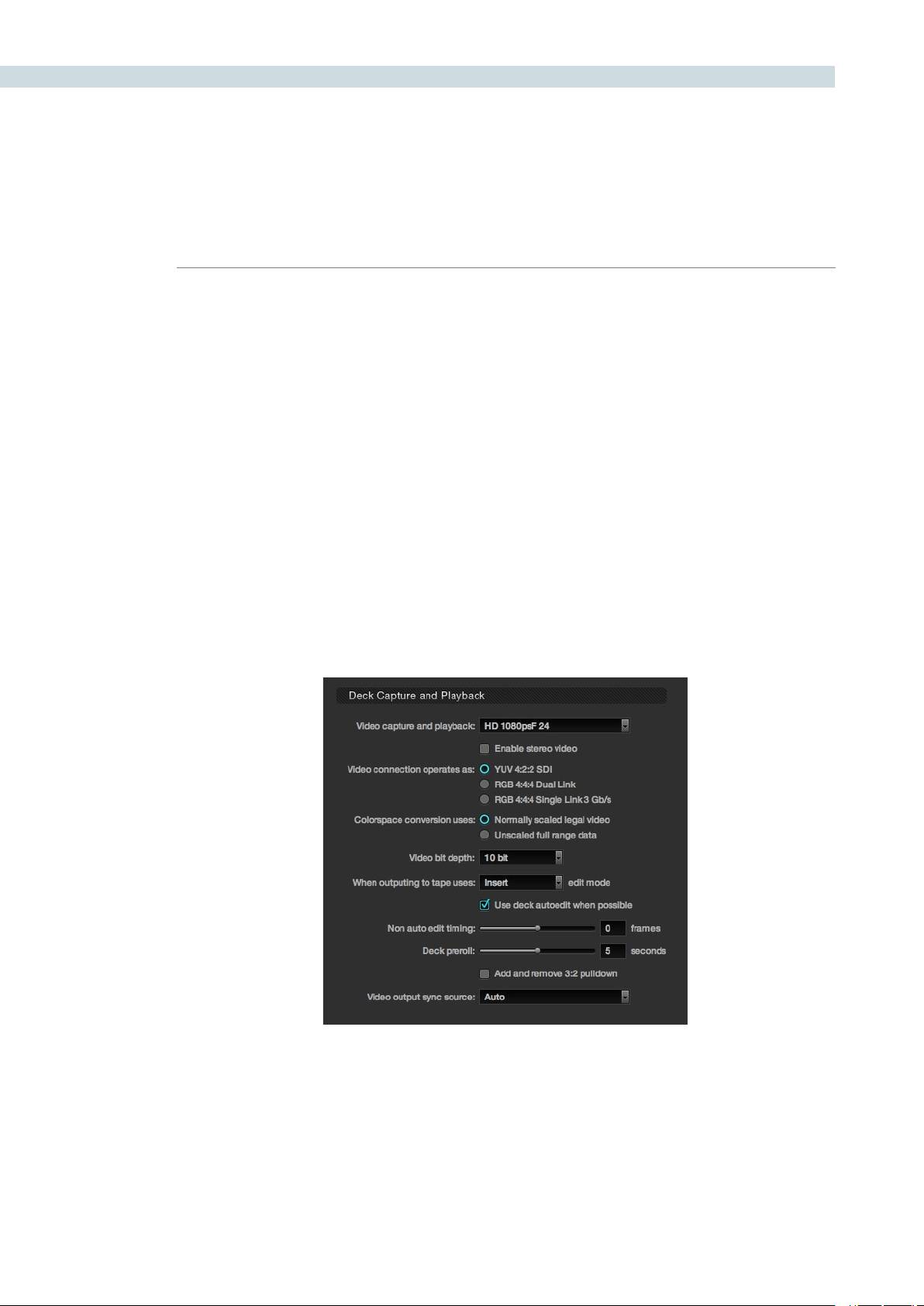
Deck Capture and Playback
The deck window is used to select the format of video that will be either imported or exported from the
system when using a video tape recorder. You should set these parameters before selecting the Deck
screenandonceset,selectthe‘Apply’buttonatthebottomoftheCongscreen.
Deck Capture and Playback

CHAPTER
CONFIGURATION
CONFIGURATION59
6
The Deck Capture and Playback controls are as follows:
Video capture & playback: Selects video standard from the pulldown list.
There is also a checkbox selection to enable stereo video ingest
and playout.
Video connection: Selects between the available connections: YUV 422 SDI, RGB
444 Dual Link and 444 single link using 3 Gb/s. Note these options
depend on which video capture card you are using and are all
available with the Blackmagic Design DeckLink HD Extreme 3
and 3D.
Colorspace Conversion: DaVinci Resolve normally uses computer RGB levels internally and so
the normally scaled legal video option will perform a color mapping
conversion to and from the SMPTE video levels when ingesting from
or recording to tape. By selecting the Unscaled full range data no
scaling will be performed in either ingest or playout.
Video Bit Depth: 10 bit is the current option.
Edit mode for recording: Select whether to record the material to tape in Insert, Assemble, or
Crash record edit mode.
Auto Edit: If your deck supports it, this is the best method to record video to
the deck. If deselected, a basic the Edit On/Off mode can be used.
Non Auto Edit timing: Adjusts the edit synchronization for the deck when auto edit is
not selected.
Deck Preroll: Set the number of seconds for preroll depending on the
performance of your deck.
Add and remove 3:2 pulldown: Enable for working with NTSC/59.94i-based material. This will remove
the 3:2 sequence on ingest or will add 3:2 on export to tape.
Video output sync source: With the Decklink this is set to Auto, but with some other capture
cardsyoumaywishtosetthesyncsourceto‘Reference’forplayout
and‘Input’foringest.
CONFIGURATION 60
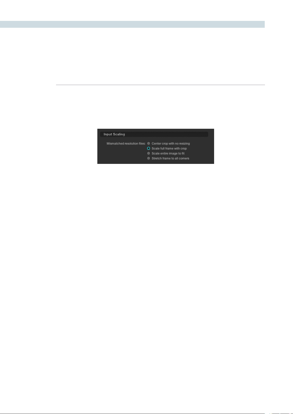
Input Scaling
When your source images are of a different size or aspect ratio to the grading timeline you need to
select how DaVinci Resolve will scale the images so they all match.
Input Scaling
CHAPTER
CONFIGURATION
CONFIGURATION61
6
The options available are:
Centre crop with no resizing This option makes no attempt to resize the image to fit the aspect
ratio selected. A simple crop is used from the center of the source
image if it’s larger than the timeline format.
Scale to full frame with crop Automatically inserts blanking within the image area to
compensate for a difference in the source to timeline
aspect ratio.
Scale entire image to fit The image will be resized in order to completely fill the frame.
In some cases, a part of the image will be cut from the left and
right sides of the source image or the top and bottom. You can
reposition the image using the Input Format sizing controls within
the Format screen.
Stretch frame to all corners When you select this option, DaVinci Resolve will fit the frame
to the output aspect ratio. In this mode, the frame edges will
be stretched to the corners and no information will be lost.
However, this option can also result in squeezing or stretching of
the image in order to fit the output format.
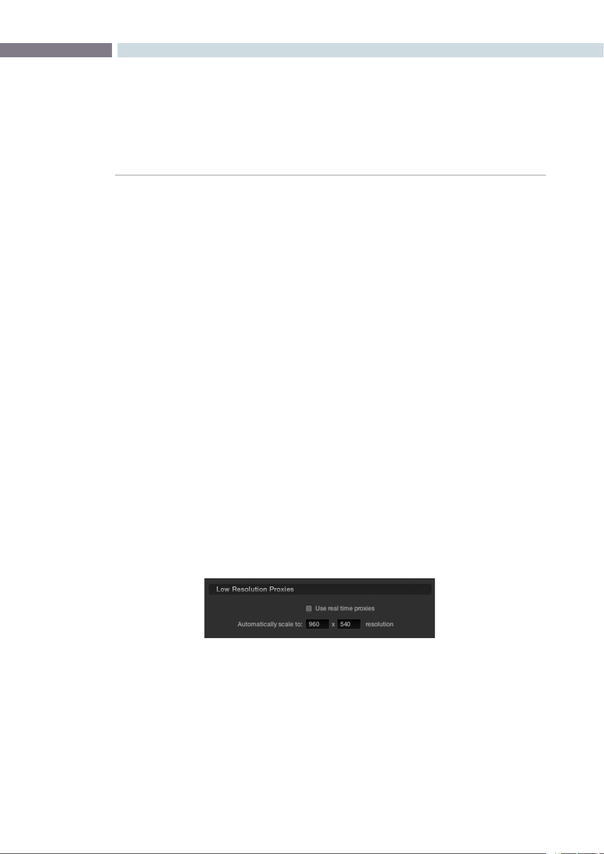
Low Resolution Proxies
The proxy mode can be enabled from the Project tab or on the DaVinci Resolve control surface. When
using the Low Resolution Proxies section of the Project tab, select the resolution for the proxy, which
is often exactly half the system resolution. Proxies on DaVinci Resolve are made with our optical-
quality resizing engine and have been used for major-budget film outs. There are two types of proxies.
The traditional pre-generated proxies which are managed from the Browse screen and often used for
4Kprojectswherethesystemhardwareonlypermitsrealtime2Kperformanceandtheadvanced‘On
the Fly Proxy (OFP) which DaVinci Resolve generates in real time.
Proxies are generally used when a complex color correction is created and the system begins to run
a little slower than real time. When this occurs, the proxy mode can be activated in order to see the
results running in real time. Alternatively, you can cache the clip to gain real time performance again.
The Low Resolution Proxies display shows the resolution of the generated proxy and the ’Use real
time proxies’ checkbox allows the operator to activate the Proxy mode.
Low Resolution Proxies
CONFIGURATION 62
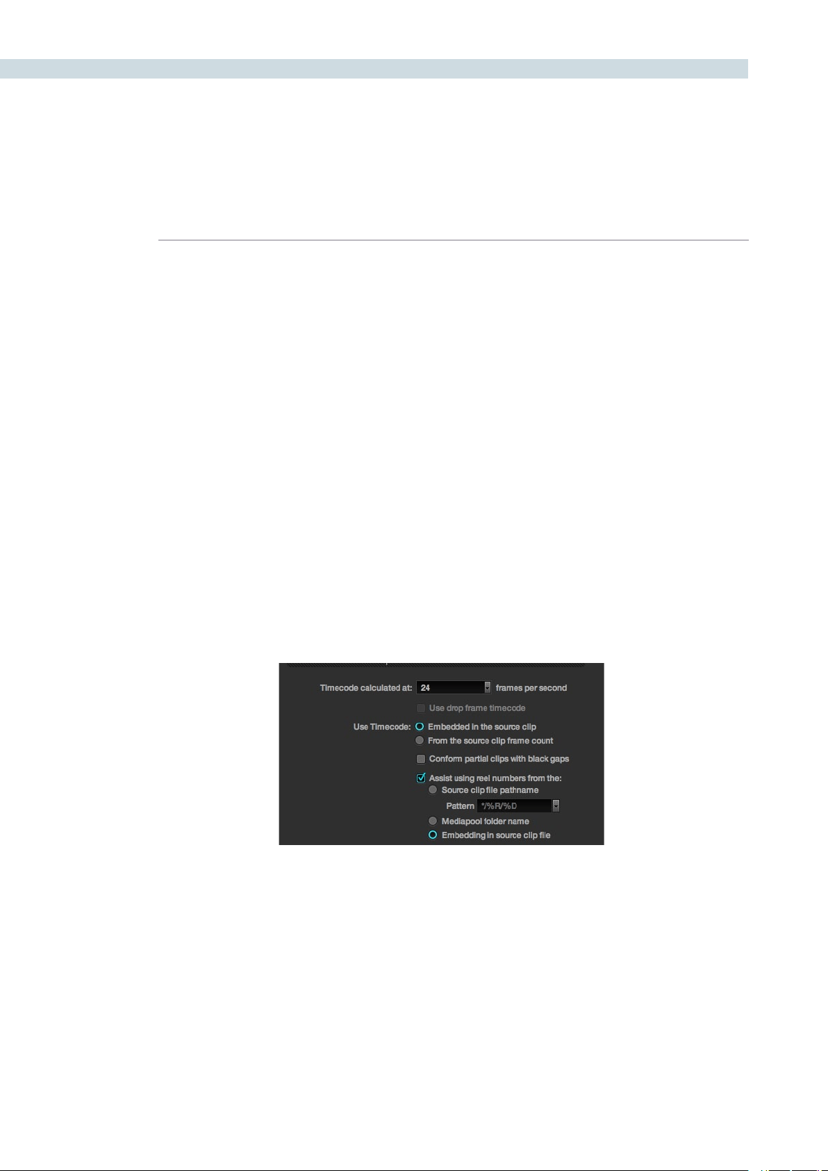
Timeline Conform Options
DaVinci Resolve will make a conformed timeline of the selected clips using a number of parameters
to make it easy to deal with missing timecodes or conflicting reel names. It is important to select the
conformed frame rate of the clips and how the header or file metadata will be used. These parameters
must be set PRIOR to selecting source clips in the Browse screen as they impact speed and frame
rate calculations used in DaVinci Resolve when establishing metadata for the grades.
SMPTE-standard DPX files contain both image and metadata for every frame independent to every
other frame. This permits DaVinci Resolve to generate complex metadata and reference the source
clips via the timecode in the DPX header. Many other formats have options for timecode and other
metadata to be recorded with each frame and DaVinci Resolve uses these on a number of occasions.
Usetimecode‘embeddedinthesourceclip’formostprojects,especiallythosethathaveDPXles,so
that conforming and applying grades to the material will be automatic. You can re-conform shots, or
even completely change the image material, and as long as DaVinci Resolve can reference the header
metadata (i.e., the timecode) for that clip, the grading metadata will automatically re-align to the new
and correct position in the timeline. If the source clips frame count is all that is available, select the
‘Fromthesourceclipframecount’option.
The ’conform partial clips with black gaps’ option will allow you to conform a clip that may not contain
all the required frames. When this option is selected you will be alerted in the Conform screen by
seeinga‘P’,representingapartialclip,withinthethumbnailoftheclipthatitislackingframes.
Sometimes you will also need assistance in conforming using reel numbers. When this checkbox is
enabled DaVinci Resolve offers a number of options. To obtain reel number information from the
Clip’s Path name, Media pool Folder Name, or from the embedding in the source clip select the
appropriate option. This is particularly helpful when working with projects that have a large number
of source reels or when the source clip file path is complex.
Timeline Conform Options

CHAPTER
CONFIGURATION
CONFIGURATION63
6
Conforming by Reel Number
DaVinci Resolve can conform clips by reel identification. There are three options for this operation.
1) Use reel number from the source clip file pathname: The reel number is derived from the
information in the directory path or the name of the file.
2) Use reel number from the Media Pool’s folder name: The conform operation will use the
folder identification within the Media Pool.
3) Use reel number embedded in source clip file: When this option is selected the system will
searchforthereelnumberinthe‘InputDeviceName’eldintheheaderoftheDPXle.Itis
important to note that the reel numbers retrieved from the header should match the reel numbers
within the EDL.
If you use the source clip file pathname for extracting the reel number, be sure to define the search
pattern that enables DaVinci Resolve to extract the reel name. This pattern consists of a series of text
characters and “wild cards” that are unique to your facility. The extraction pattern is interpreted from
right to left.
Here are a series of search characters that may be used.
? This will look for matches of any single character.
* This wildcard will create matches for any sequence of zero or more characters.
%R Use this option in order to specify the reel number’s location. It is important to note that reel
numbers may contain any character, but should not contain any directory separators. The real
number extraction pattern %_R is used to extract reel numbers and strip out the r3d file name
underscore for FCP EDL’s.
%D This will match any directory name or file name. It will not include a forward slash.
To test the extraction path select the pulldown arrow next to the current path and a dialog will open.
Enter your test patten using the search characters and then the path to a clip you wish to extract. Press
the‘Test’buttontoviewtheresultoftheextractiontest.Ifthereelnumberinformationextractedproves
correct,selecttheapplybuttontoplacethepatternintothe‘TimelineConformOptions’display.
Examples of Reel Number Path Extractions
In order to better understand how this process works, there are several examples showing the various
methods of reel number extractions. The / is used as the separator between control parameters.

CONFIGURATION 64
Example 1: This example shows the reel number stored within the parent folder name of the clip.
Pattern: */%R/%D
Clip Name: vol0/MyMovie/Scans/004B/Frame[1000-2000].dpx
Reel number: 004B
Parsing takes place from right to left so to analyze this pattern start at the right end. In this case the
%D matches to the file name “FrameNNNN.dpx” where NNNN is the frame number in each file of the
clip. Moving left of the file name, the /%R/ section of the string is next. This specifies that the reel
number will be the entire name of the parent directory immediately above the file. Then the * at the
beginning of the string says match any pathname in front of the directory name that has the reel
number. This string would find the parent directory regardless of how many levels deep it is nested
on the directory path.
Example 2: Here we see the reel number stored in the parent folder name of the clip along with being
prefixed by reel number.
Pattern: */????%R/%D or alternatively */Reel%R/%D
Clip Name: /vol0/MyMovie/Scans/Reel1234/Frame[1000-2000].dpx
Reel number: 1234
In this example both of these extractions patterns produce the same result. They are also similar to the
first example. The reel number is still in the parent directory name but in this case it will have the fixed
characters “Reel” prefixed in front of the reel number. The first pattern with ???? would actually match
with any 4 character in front of the reel number. The second pattern is more specific and would only
match the word “Reel” in the directory name.
Example 3: This example will show the reel number stored within the parent folder name two directory
levels up.
Pattern: */%R/%D/%D
Clip Name: /vol0/MyMovie/Scans/004B/134500-135000/Frame[1000-2000].dpx
Reel number: 004B
This example is again similar to example 1. The difference is that the reel number is the directory name
two levels above the clip. In the example 1, the reel number was in the directory name only one level up.
Example 4: Finally, we see the reel number that is embedded within the clip name of the material.
Pattern: */Reel%R_*
Clip Name: /vol0/MyMovie/Scans/Reel004B_[1000-2000].dpx
Reel number: 004B
This example shows a method for extracting the reel number for the file name of the clip. Again, starting
at the right the two pattern characters “_*” match any series of characters up to the first underscore
character. Which in this case will pick up the file extension (.dpx) and the frame number portion of the
lename.Next,the“/Reel%R”charactersindicatethereelnumberisthecharactersbetweenthe‘/Reel”
and _ character. The * at the beginning of the pattern will match a file path any number of directories
deep in front of the file name.

CHAPTER
CONFIGURATION
CONFIGURATION65
6
Reel Number Support from Final Cut Pro EDLs
To be able to handle larger than 8 character reel numbers from Final Cut Pro EDLs, DaVinci Resolve
supports extraction of the reel name using the comments.
On the settings tab of the config screen, select the option called “Extract Reel Names from
EDL comments”.
e.g. Consider the following event in the CMX EDL
001 REEL02_T V C 01:02:54:24 01:02:50:24 01:00:54:24 * FROM CLIP NAME: REEL02_TEST.MOV
DaVinci Resolve will read the reel name as REEL02_TEST
This option is especially useful for conforming CMX EDLs generated with reference to RED r3d clips,
which have longer than 8 character reel numbers.
Changing the Conform Frame Rates
As mentioned, it is important that you apply the correct frame rate for the material within the Conform
Options display prior to adding material into the Media Pool or creating a Master Session within the
Conform page.
If you enter an incorrect frame rate in the Timeline Conform Options display, the resulting source
timecodes that are calculated will be incorrect. Once information is added into the Media Pool or a
Master Session is created, this control within the Configuration screen will become unavailable.
To change the value within the Timeline Conform Options display you must delete the Master Session
and remove any information in the Media Pool.
CONFIGURATION 66
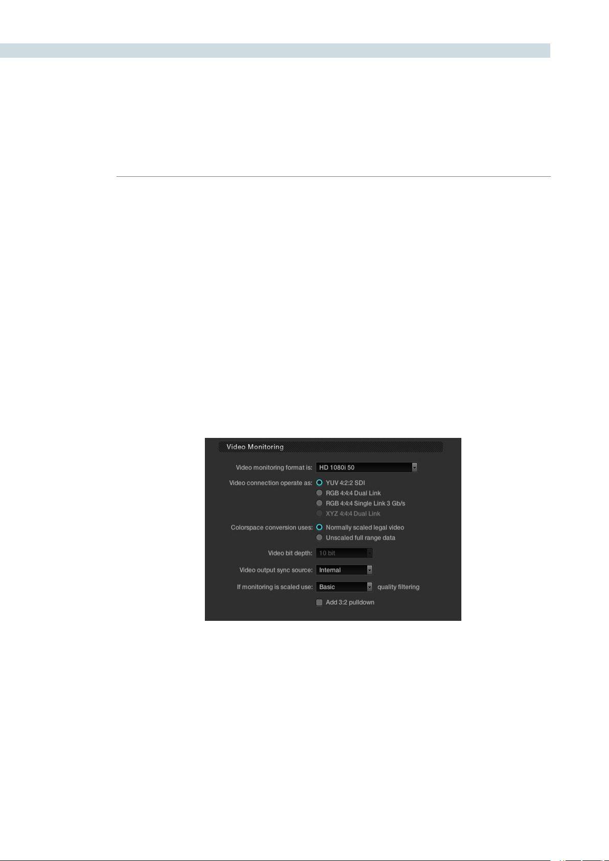
Video Monitoring
The Video Monitoring display should be adjusted to reflect the monitor you use for color correction.
The settings here have frame rate and screen refresh implications, so making the correct selection
is important.
For example, if you are working with 2K files in a 2K environment but color correcting using a high
definition monitor, you should select the appropriate HD standard for that monitor.
There are many options for the video monitoring format, so first select one from the pulldown list. Then
selectthevideoconnectiontooperateasYUV422,RGB444dualorsinglelink;ortheXYZoption.
The Colorspace conversion selection will perform a color mapping conversion to work with data to
video level translations. Remember your images are often stored in full 0-1023 data but the monitor is
generally expecting, and can process, the 64-940/960 video levels as specified by SMPTE. If you wish
to monitor the full 10-bit data range (0- 1023) of the monitoring output, simply change the colorspace
conversion to unscaled full range data. If the Colorspace conversion is set to the normally scaled legal
video then the data range is scaled down to video range (64-940/960).
With some video I/O and monitoring cards there is an option for 12-bit monitoring. If applicable to
your system, you may select the 12-bit option. This is often used when monitoring through a projector
capable of accepting a 12-bit HD-SDI input.
The output video sync source control is used with some video I/O cards but not required with all. It
will select between internal and external bi-level or tri-level synchronization. This is particularly relevant
when two NVidia SDI optional cards are installed for Stereoscopic 3D grading as they both must have
the same physical input sync, as the 3D processor and display device.
Video Monitoring

CHAPTER
CONFIGURATION
CONFIGURATION67
6
The filter selection for monitor scaling is usually set to basic and only enabled to smooth edges when
viewing with a video projector and a very large screen. These settings minimize any high frequency
artifacts that may be seen. This may also be noticeable if you have a 2K or HD project but are monitoring
on a SD monitor. Normally this should be in the basic mode. The other options, Bilinear, Bicubic and
Bspline will have different impact depending on your display device so you may need to test each to
verify which is best for your facility.
The 3:2 Pull down switch can be utilized for monitoring in NTSC while the user grades 24fps material.
If you have selected NTSC, 59.94i or a playback rate of 24fps will automatically activate this option.
CONFIGURATION 68
From the LUTs tab on the Configuration screen you may select various Input, Output, or Display look-
uptablesorLUTs.Thereisalsoanoptionto‘ApplyLUTtoWaveform’,whenchecked,willapplythe
selected LUT to the DaVinci Resolve Waveform display. This can be useful when working in Video
grading mode when a 3D LUT has been applied.
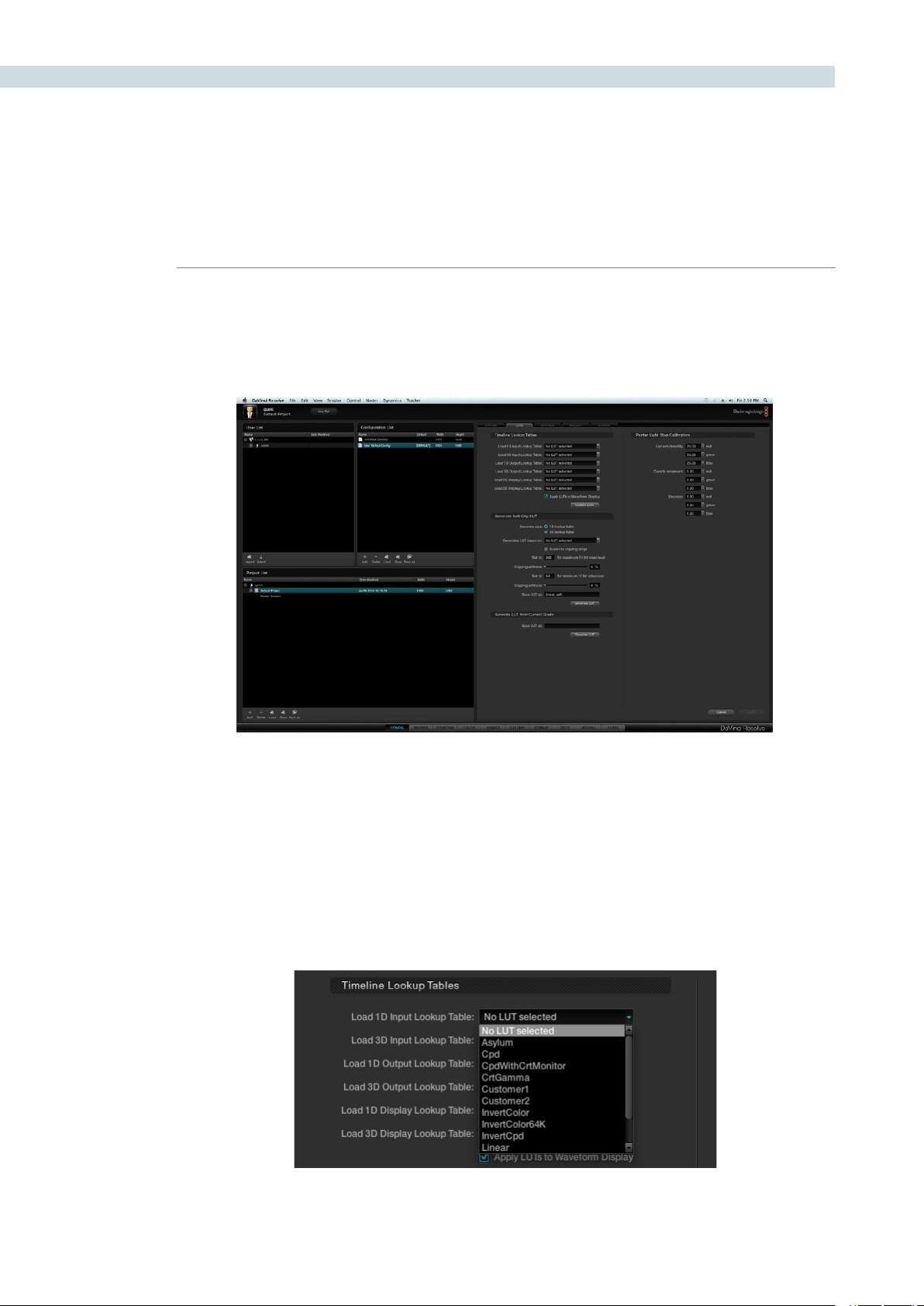
Timeline Lookup Tables
Within the Timeline Lookup Tables display are the factory preset lookup tables along with those that have
been generated or imported into DaVinci Resolve. If new lookup tables are imported into the system, the
Update lists button should be clicked to refresh the contents of the pull down menus. Resolve uses both
1D and 3D LUTs.
3D LUTs that are generated in DaVinci Resolve are in the .cube format and are configured as 33x33x33
cubes in 32 bit floating point. DaVinci Resolve can also read and use LUTs in the Cinespace format.
LUTs Tab
LUT Tab
LUT Table
CHAPTER
CONFIGURATION
CONFIGURATION69
6
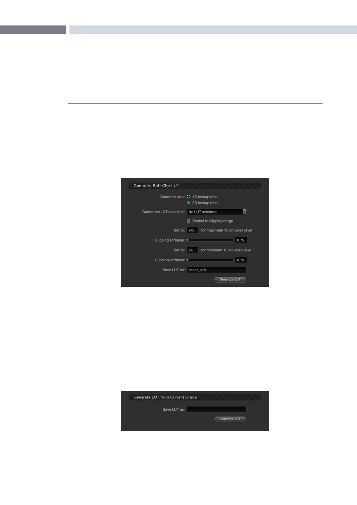
Generate Soft Clip LUT
To edit an existing LUT by adding soft clipping to it, select either the 1D LUT or 3D LUT option then the
original LUT from the pulldown list. You can then scale the new LUT to a clipping range (i.e., 940) for the
maximum 10-bit video level as well as the minimum clipping level. The clipping softness controls allow
you to apply soft ramps to the high and low clip level. Type in a name for the new LUT, and generate by
clickonthe‘GenerateLUT’button.ThenewLUTwillbeavailablethenexttimeyouupdatetheLUTlist.
Generate LUT from Current Grade
DaVinci Resolve offers a LUT generation and trimmer tool that you can use to tweak existing LUTs or
build new LUTs. These LUTs can be used internally or for other LUT management products as “Looks”.
The 3D LUT generated is in the .cube format, which is readable by the Blackmagic Design HDLinkPro.
The 3D LUTs you generate are stored at /Library/Application Support/Blackmagic Design/DaVinci
Resolve/LUT/CineSpace
Before you can use this feature, you need access to a unique DaVinci Resolve Trim_LUT0.DPX image,
which is located at /Library/Application Support/Blackmagic Design/DaVinci Resolve/trim_lut0.dpx
Generate Soft Clip LUT
Save LUT as

CONFIGURATION 70
There are two workflows for generating the LUT:
Workflow A. Using the color correction controls and the Trim LUT DPX image within
Resolve to generate the LUT.
Workflow B. Using an external software/product capable of applying a color correction
effect which you want to capture as a LUT.
Workflow A:
1. Set your resolution to High Definition within the Config screen.
2. Load the trim_lut0.dpx file located at /Library/Application Support/Blackmagic Design/
DaVinci Resolve/trim_lut0.dpx into the Browse screen’s media pool. Within the Color screen
you will now see the Trim LUT file within the thumbnails.
3. Select a normal image clip on the timeline and color grade the desired offset or effect. You
can grade this image like any other. Once done, select the Trim LUT clip on the thumbnail
timeline with your mouse to make it the current clip.
4. With the Trim LUT file as the current clip, using the center mouse button, click on the clip you
just graded with the desired offset grade. This offset grading will now be applied to the Trim
LUT file. (This is a standard DaVinci Resolve copy grade operation).
5. Then, within the Config screen LUT tab, assign a name to the new LUT to be generated using
the‘SaveLUTas’window.
6. Clicking on the Generate LUT button will create the new LUT that is an offset grade. It’s the
grade you made to the original image. This LUT can now be selected like any other.
7. Update the LUT list that’s at the top of the LUT tab and select as an input, output or display
LUT as required. You can also use the LUT on the color page in any node.
The new LUT will appear in the 3D LUT options and can be used in any of the places DaVinci Resolve
normally uses 3D LUTs. It is also possible to capture an external Trim LUT or generate one with the
Resolve LUT configuration and resolution by placing this Trim LUT Clip into an external device that
applies a LUT.
Trim LUT Clip (One Frame)
CHAPTER
CONFIGURATION
CONFIGURATION71
6
Workflow B:
1. Load the trim_lut0.dpx file located at /Library/Application Support/Blackmagic Design/
DaVinci Resolve/trim_lut0.dpx into the external device or feed the external device the image
via an HD-SDI connection.
2. MakesuretheexternaldeviceisoutputtingHDin‘Fulldatalevels’mode.
3. Connect the output video from the external device to the input video of DaVinci Resolve.
4. Using the deck Input interface on DaVinci Resolve, crash record or capture a few frames. You
only need a few.
5. Use the captured frames as the test pattern in Workflow A above to generate the new LUT.
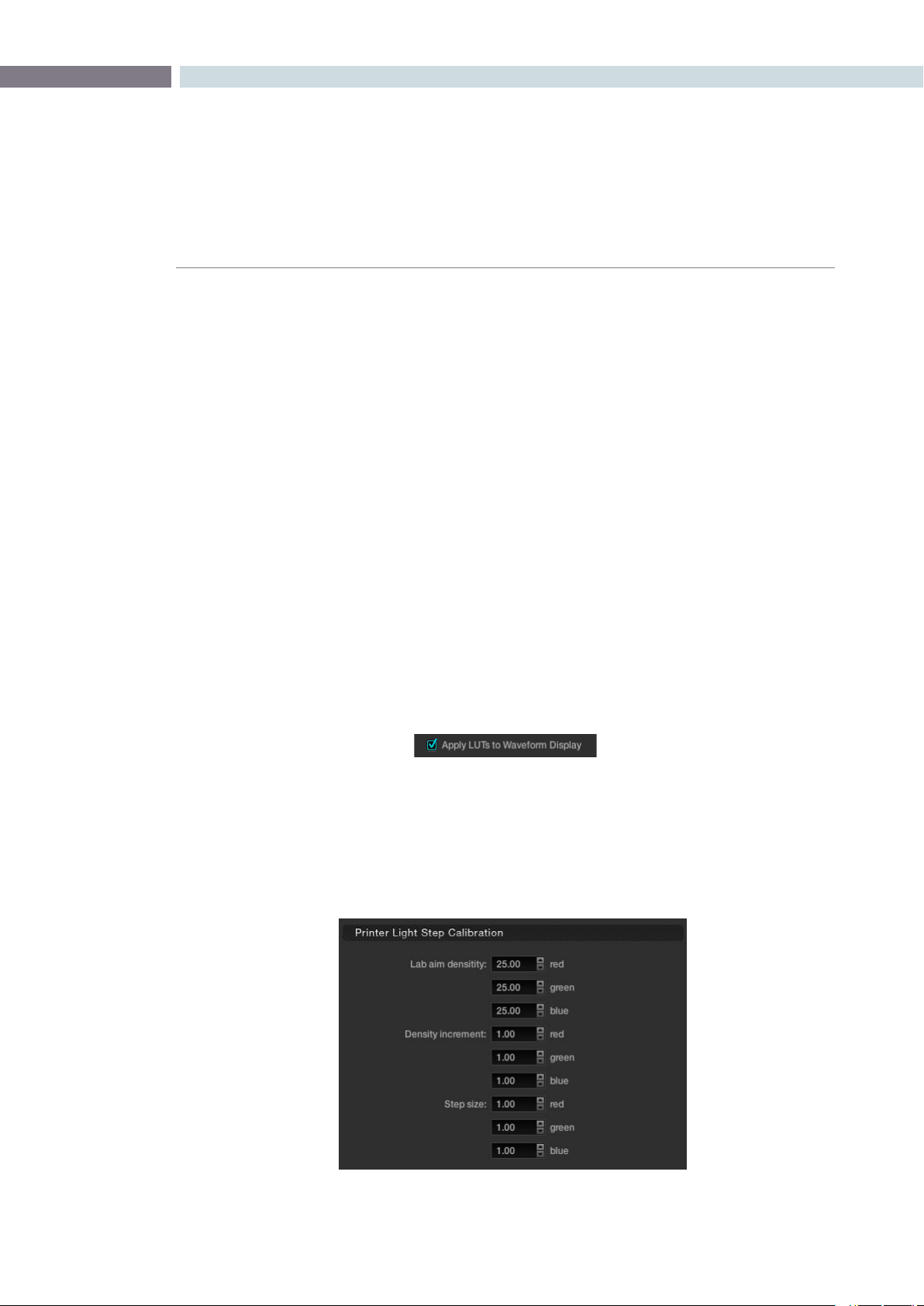
Apply LUT to Waveform
Often when grading feature films you will use a LUT in the grading monitor path to emulate the film
recorder, film lab and print stock used for a film out to ensure the print shown in the cinema will appear
the same as the image on your grading monitor. Physical and hardware exceptions apply, but the principle
is that with the film out 3D LUT in the Display path, what you see is what you get.
Of course often you don’t want this LUT to influence the waveform monitor displays as these are providing
an accurate indication of the levels and phase, etc. of the image and are not subjected to the limitations
of the grading monitor calibration or the film out/film lab/print stock limits. With DaVinci Resolve, you can
select to apply or not apply the LUT to the waveform displays by using the checkbox.
Printer Light Step Calibration
For film projects, when you have a tight integration with a film lab, it is possible to adjust the printer
light calibration sets to match the lab you are using. You should work with your lab technician to set up
the Lab Aim settings, the Steps adjustments, which is an incremental value, and the Density Increment
adjustment, which is the amount of correction applied within each step. Generally the Step and Density
values will be identical, but this will be up to your lab and your preference.
Printer Light Step Calibration
CONFIGURATION 72
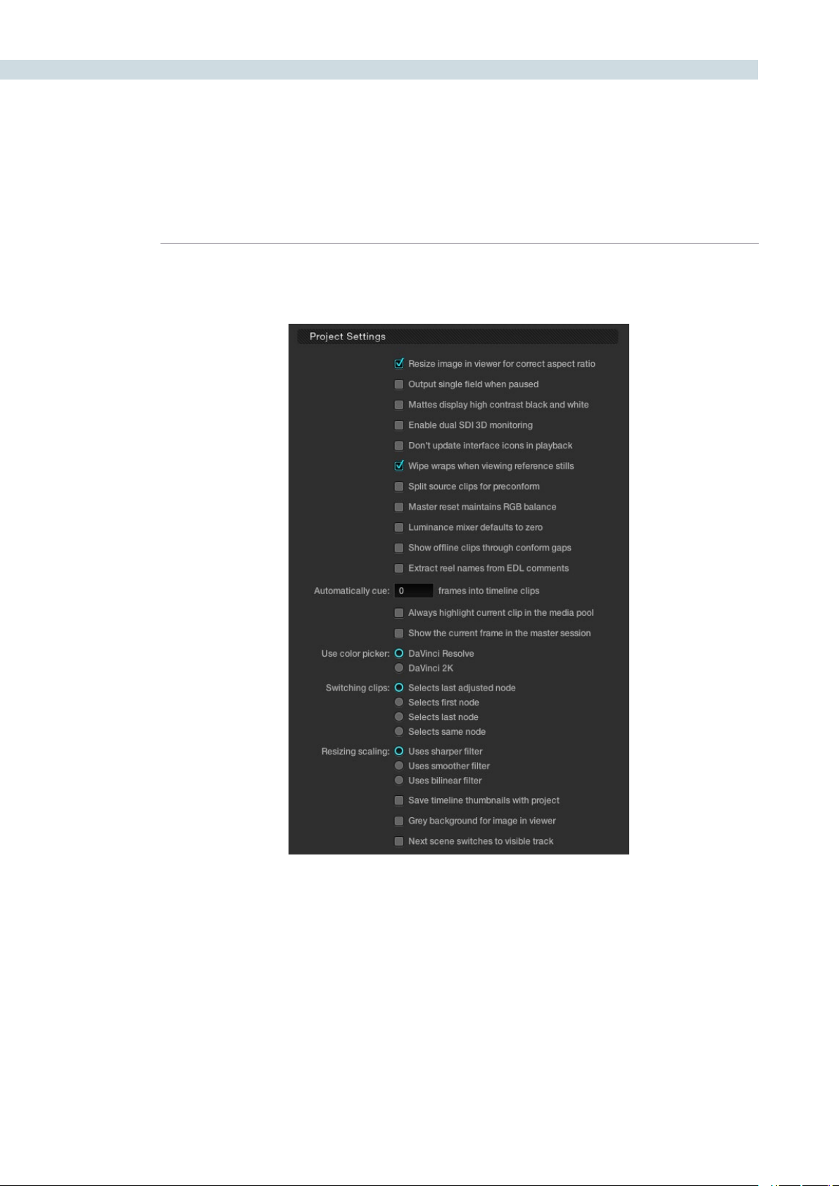
The Settings tab displays a number of checkboxes used to customize the operations within DaVinci
Resolve for the current project.
Project Settings
Settings Tab

CHAPTER
CONFIGURATION
CONFIGURATION73
6
Project Settings
The first section within the Settings tab is for Project options.
Resize image in viewer for correct aspect ratio:
This control will select between using a square or non-square
pixel aspect ratio within the viewer. This is important when
working with SD images which do not have a square pixel
aspect ratio.
Output single field when paused: This setting will reduce flicker when grading using a computer
monitor or when working with interlaced material. Ordinarily,
when viewing interlaced material in stop or pause mode,
field one is displayed followed by field two. Depending on
the image, this can result in a flicker on the display. When this
option is enabled, only field one will be shown on the monitor
when playback is paused; however both fields will be shown
when the clips are played.
Mattes display high contrast black and white:
This option will show a black and white display (i.e., high
contrast) rather than the standard grey matte when
highlighting a secondary color correction isolation.
Enable dual SDI 3D Monitoring: All DaVinci Resolve systems can generate a side by side
display that can be sent to a Stereoscopic monitor via the
HD-SDI output of a DeckLink HD Extreme card. When dual
SDI 3D monitoring is enabled, each eye is output separately
at full resolution on either the DeckLink HD Extreme 3D, or the
NVIDIA dual SDI monitoring outputs. In this mode, split-screen
wipes and cursors will not be visible on the grading monitor,
nor will you be able to view image resizing.
Don’t update interface icons in playback:
Selecting this option forces a priority to update the playback
image at the selected frame rate by reducing UI updates.
This mode is helpful when complex grades are used on
low processing power systems or when working with
higher resolutions.

CONFIGURATION 74
Wipe wraps when viewing reference stills:
With this option the stills wipe mode will wrap around rather
than stop at each side of the screen.
Split source clips for Pre-conform: Select to split the source clip in the Media Pool and the
master session when using the “Preconform” operation.
Master reset maintains RGB Balance:
This control defines how the panel reset buttons reset the
primary color correction. Normally, a reset will return the
primary correction values to their default values. When this
option is selected, reset will function as follows:
1) Clicking the master reset key will reset the YRGB values so
that the overall values are kept and the ratio of YRGB to each
other is maintained.
2) Clicking the RGB reset button will find the average value
of RGB, and set the RGB to that value.
Luminance mixer defaults to zero: Selecting this option sets the Y of the YRGB value for all grades
to zero. This is needed for export of an ASC-CDL and will have
an impact on all your grades if you have used the Lum Mix
control.
Show offline clips through conform gaps:
Normally, if there is a missing clip in a conformed timeline the
position of the clip is shown on the thumbnail and viewer as
black. This option permits the offline clip, with the appropriate
timecode synchronization, to be displayed in place of the black
orto‘shinethrough’theholemadebythemissingclip.
Extract reel names from EDL comments:
Some file formats have reel names longer than eight characters,
and also complex file name structures. The RED r3d file is an
example. This option allows DaVinci Resolve to extract the reel
names from the EDL comments, as often used in an FCP EDL.

CHAPTER
CONFIGURATION
CONFIGURATION75
6
Automatically cue number of frames into timeline clips:
Use this control to change from the default cue point
operation, the first frame of the clip, to some number of
frames after the first. This is handy if the source material has
black or camera rollup flashes at the beginning of each clip.
Always highlight the current clip in the media pool:
If you select this option, any clips that are current on the
Color or Conform screen will be automatically identified in
the media pool within the Browse screen.
Show the current frame in the master session:
When selected, the current frame for the current session
will automatically be identified on the master session. If
you are in the Color screen with an EDL/timeline open and
you switch to the master session, DaVinci Resolve will auto
cue to the same frame within the master session. This is
particularly helpful when working with multiple sessions and
local versions of grades.
Use color picker: The Color Picker Style setting changes the manner of
selecting colors within the Secondary color correction
controls. DaVinci Resolve is the normal and modern mode,
however some colorists who are familiar with the legacy 2K
prefer the DaVinci 2K mode.
Switching clips selects: When switching clips, DaVinci Resolve can switch to the
same or another node in the node graph. The four options
below determine which node is selected:
Last Adjusted Node: Each clip retains its node
settings. This is the normal
setting.
First Node: The first node is selected as the
current node.
Last Node: The last node is selected as the
current node.
Same Node: The same node will be selected,
if available.
Resize scaling uses: When resizing images with DaVinci Resolve, particularly with
SD images, you may want to change the resizing filter from
thenormal‘Usessharperlter’settingto‘Usessmoother
filter.’ Remember, if your project uses HD-resolution media
and you’re outputting an SD version to tape, this is a resize of
theimagetoSD.Weadvisethatyoureviewthe‘Sharper’and
‘Smoother’ltersettingstoselectyourpreference.Ifyou’re
working on a system with less processing performance, you
canalsochoosethelessprocessor-intensive‘Usesbilinear
filter’ option for better performance previews while grading,
before switching to one of the higher-quality options
for rendering.
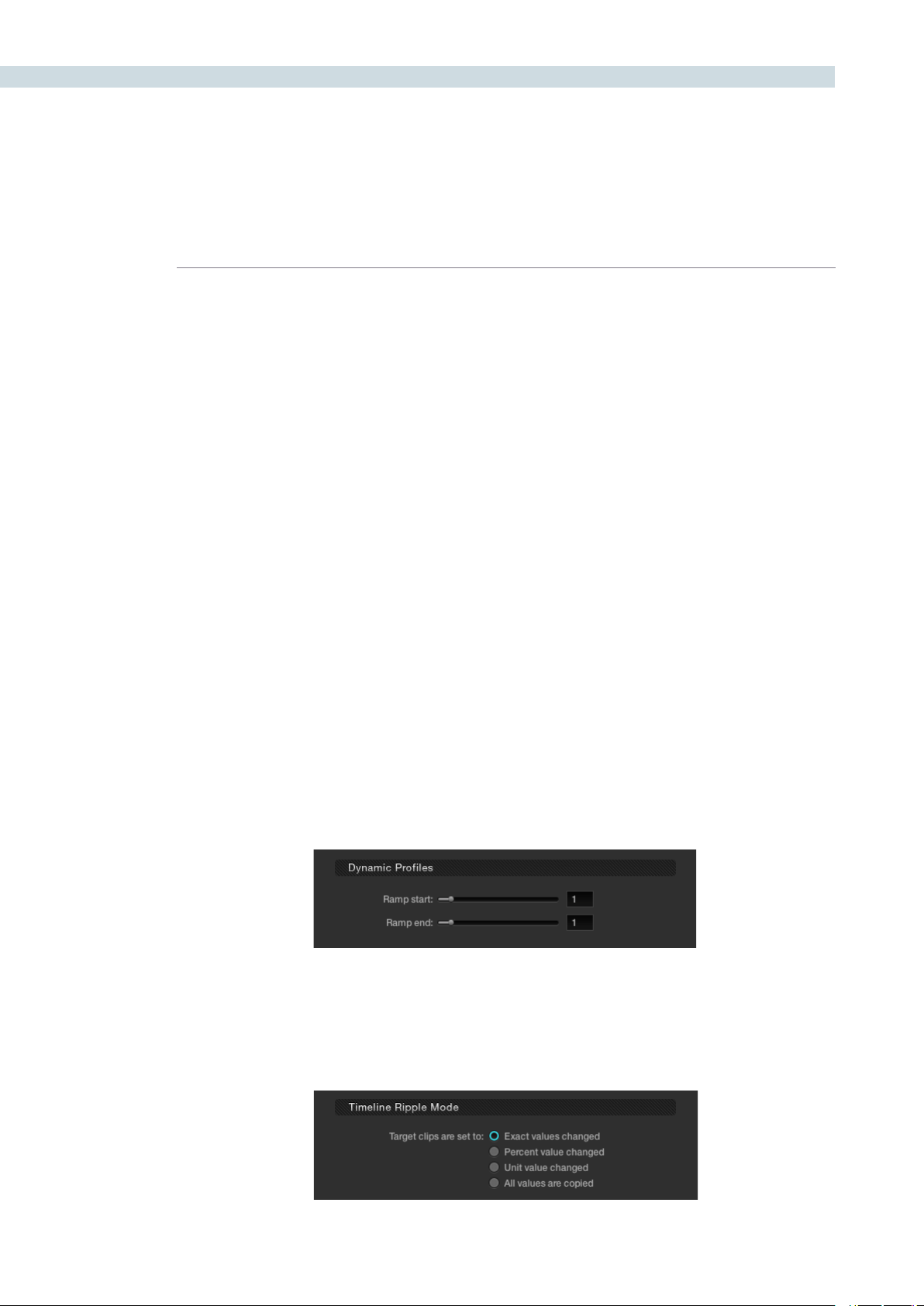
CONFIGURATION 76
Save timeline thumbnails with project:
To minimize project size and maximize speed of your project
Save and Load operations, you should leave this checkbox
un-checked. If you select the checkbox, all of your timeline
thumbnails will be stored with every project (Save and Auto
Save). This provides a good history of the project, but takes
much longer to complete and uses more hard disk space.
Grey background for image in viewer:
There are occasions when it is easier to see the image
blankingorminorPTZRchangesintheviewerwithagrey
rather than black background. Select this option to make the
background around the viewer grey.
Next scene switches to visible track:
When grading a multiple track timeline colorists may prefer
tousethisoptiontoalterthe‘nextscene’operation.Normally
when‘nextscene’isselectedonthepanelsorkeyboard
shortcuts the viewer would display the next thumbnail in
thethumbnailtimelinebutwiththe‘Nextsceneswitchesto
visible track’ option the scene that is displayed is the highest
track in a multiple track timeline, then switching to the next
lower track when next scene is selected again.
Dynamic Profiles
Using the slide controls you can adjust the default curve for the start and end parameters of for all
dynamics. Individual adjustments for clips can be made in the dynamic timeline on the Color screen.
Timeline Ripple Mode
This section determines the default setting for a correction ripple, i.e., how to copy grades or ripple
them from one clip to another.
Dynamic Profiles
Timeline Ripple Mode
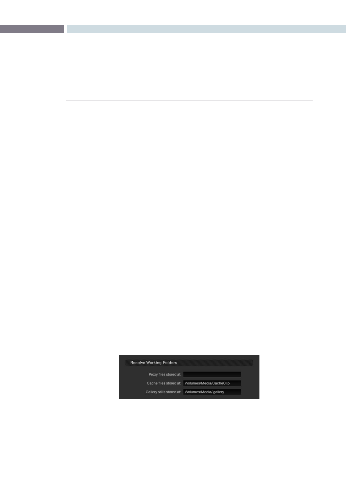
CHAPTER
CONFIGURATION
CONFIGURATION77
6
In each case the target clips are set to:
Exact values changed: Changes made to the current scene are rippled to the
additional scene(s) using the exact control setting changes.
For example, if Master Gain in the current scene is changed
and set to 75 percent of its range, each scene rippled will
then have a Master Gain setting of 75 percent. This is useful
for setting consistent levels throughout the entire list.
Percent value changed: Any change made to the current scene is rippled to the
additional scene(s) by the same percentage of change. For
example, if the current scene has a Master Gain level of a
hundred units and is changed to ninety units, then each
rippled scene will have a relative reduction of 10 percent
in its Master Gain level. This modification is based on the
Master Gain level in the rippled scene(s) before the change.
So if a particular rippled scene originally had a Master
Gain level of fifty units, the relative change of 10 percent
would reduce the rippled scene’s video gain level to forty-
five units.
Unit value changed: Any changes made to the current scene are rippled to the
additional scene(s) by the same number of units of change.
For example, if the current scene has a Master Gain level of
eighty units and is increased to ninety units, each rippled
scene’s master gain level increases by ten units.
All values are copied: The current scene grade is rippled, or copied, to other
events. No comparison is made with the original scene
memory, and all memory parameters are rippled.
Working Folders
These controls are used to change the file path for Proxy, Cache and Gallery storage data.
It is important that these settings are not set to the computer’s system disk as it will quickly fill up with
proxies/cache. If this happens it’s likely your computer will not boot the next time you start.
Resolve Working Folders
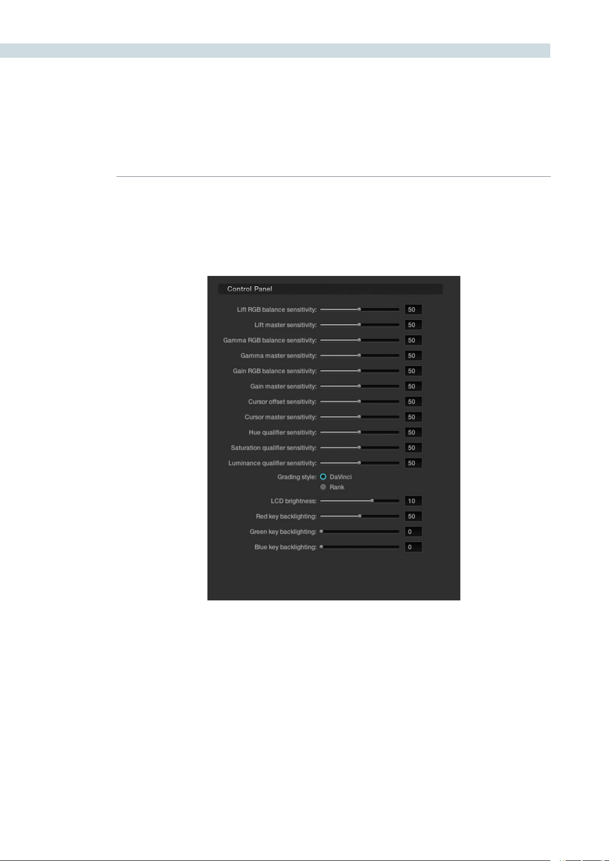
CONFIGURATION 78
Control Panel
These controls set the sensitivity of the primary grading controls for Lift, Gamma and Gain balance and
master, the Cursor trackball offset and master, and also the Hue, Saturation, and Luminance qualifiers.
There are two options for the trackball Grading style, labeled DaVinci and Rank. Most users will be
familiar with the standard DaVinci controls as this mimics the Vectorscope. If you move the trackball to
the right, and lower, a little, the image will become more blue; move to the top for more red and to the
lower left for more green. The Rank settings are somewhat different, so this option is for users who are
familiar with color controls that the Rank control system offered.
There are also settings on this screen for the DaVinci Resolve Control Surface LCD brightness and the
color of the key backlighting.
Control Panel Layout
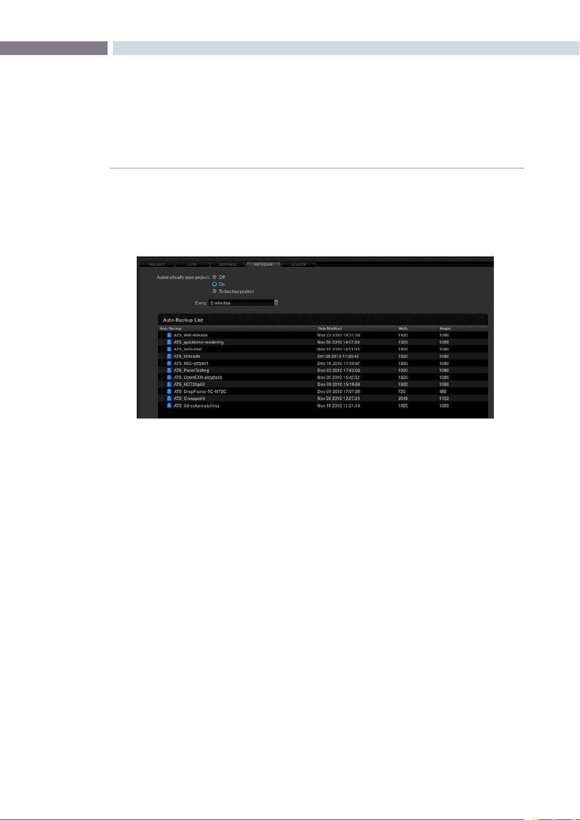
CHAPTER
CONFIGURATION
CONFIGURATION79
6
Your project database is extremely valuable, so DaVinci Resolve has an Autosave feature that will make
copies of your active database while you work. On the Autosave tab you will see the list of files that
havebeenstoredandyoucansettheintervalforautosaves.Simplyclickonthe‘Load’buttontorecall
a project from this list.
ColoristscanselecttheAutosaveto‘On’forfastincrementalsavingofthecurrentprojector‘Tobackup
project’ for a full backup of the current project.
The incremental autosave mode emulates a manual save and is quite fast. While the full backup takes
longer than the incremental autosave and is often used by colorists at the end of each workday or
grading session.
Autosave Tab
Autosave tab
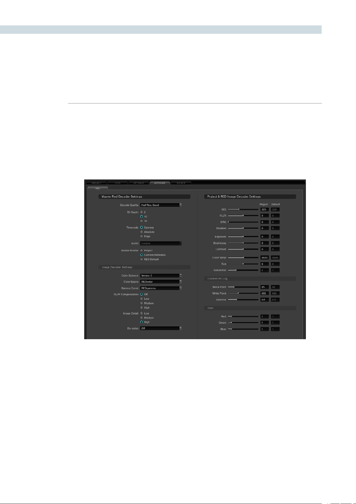
CONFIGURATION 80
DaVinci Resolve natively supports a number of file formats, some of which require you to set decoder
parameters. When processing r3D files from the RED camera you can set the control variables from the
RED sub tab within the DaVinci Resolve Source tab. Individual controls are also available for each r3d
clip on the Color screen. You may also select a clip or number of clips in the Media Pool and access the
settings that way. In the Media Pool you can select clips by various criteria and assign settings specific
to a given camera, shoot day, etc. The same settings found on the Config page are available per clip on
the timeline pop-up, and you can select the DaVinci Resolve config settings as well.
Source Tab
RED File Decode Settings
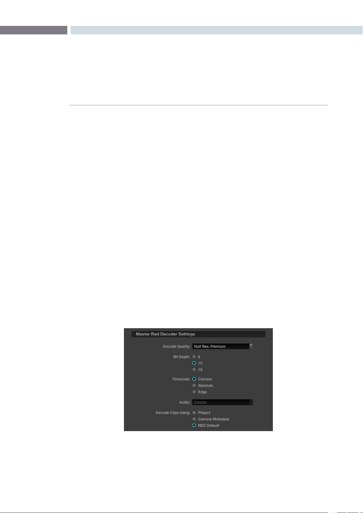
CHAPTER
CONFIGURATION
CONFIGURATION81
6
Master Decode Settings
DaVinci Resolve provides RED source clip settings in two ways: project and clip based. You can set
the decoder for the entire project using these controls;
Decode Quality: The decode quality will have a direct impact on the performance of the
system, so you may want to grade in a resolution which provides real-time
playback, then use the config settings to switch to a higher quality/resolution
for rendering. Performance will depend entirely on the hardware capabilities of
your system.
DaVinci Resolve offers RED decoding on all of its systems using the onboard
CPUs and can also decode in 4K Premium quality on a suitably equipped
system using the RED Rocket card.
Bit Depth: Resolve will decode the r3d files and generate an 8, 10 or 16-bit image file.
Using 16-bit for maximum quality may impact playback performance on
some hardware.
Timecode: You may set DaVinci Resolve to use either the Camera timecode, the Absolute
code, which is the time of day timecode, or Edge code which is the timecode
that defines each frame. Edge timecode is particularly valuable for off-
speed recordings.
Audio: Enable or Disable audio playback. (This feature is to be implemented in a
future release.)
Decode Clips Using: This is a key parameter to define. Decode the RED images using the project-
basedsettingsfoundonthisscreen(madeactivebychoosing‘Project’here),
or the metadata recorded by the camera when making the clip, or use the
RED default settings.
Master Red Decoder Settings
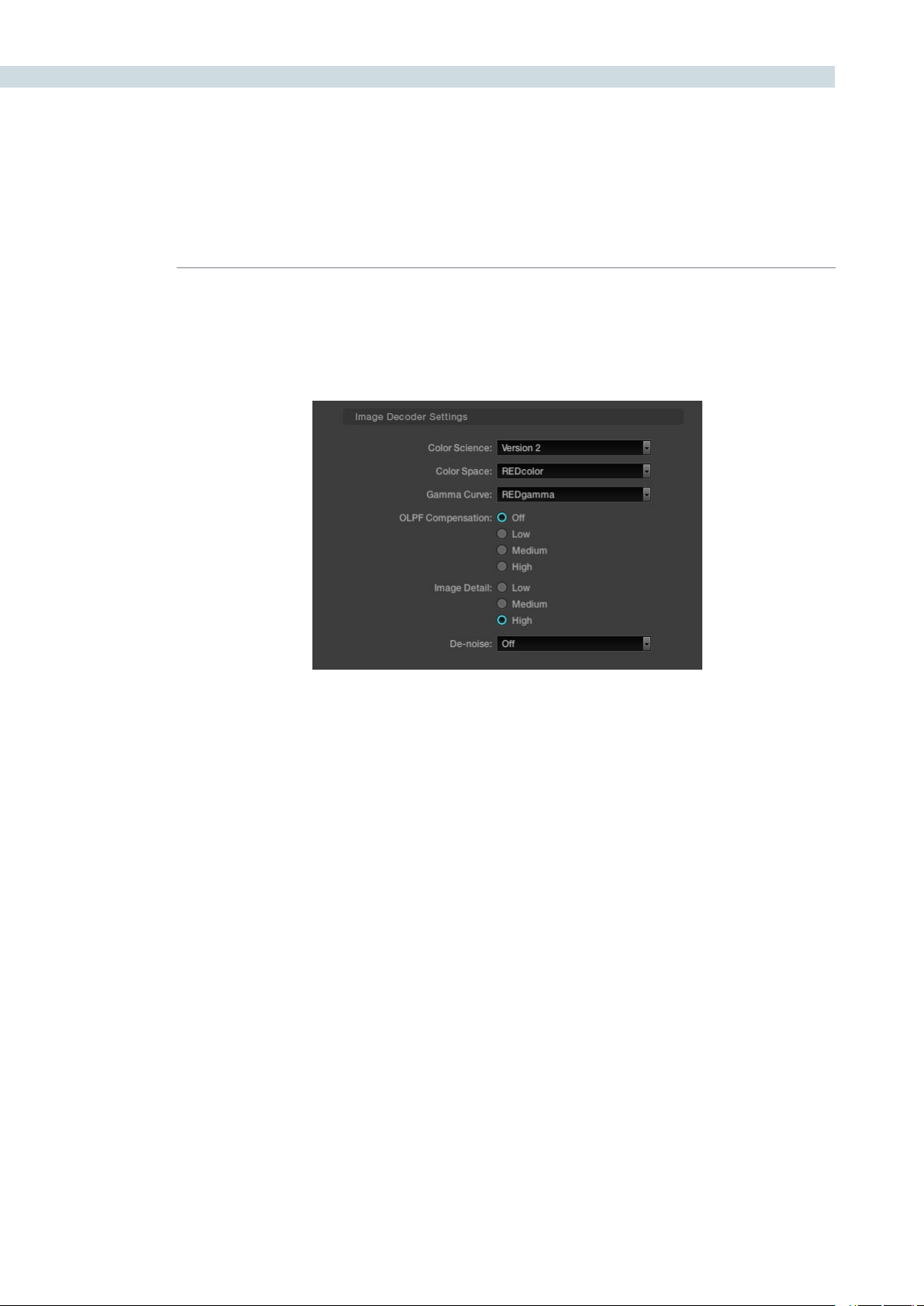
CONFIGURATION 82
Image Decode Settings
IfyouchosetomodifythedecodingparametersforyourREDlesbychoosingthe‘Project’optionin
the Decode Clips Using setting, the following controls become active.
Color Science: The original REDone camera builds used a different color science to the
more recent builds. Select here as appropriate.
Color Space: Red offers a number of color space options when decoding the RAW images:
REDcolor, which is default color space; Camera RGB, which bypasses the matrix
in the camera and uses uncorrected sensor data; REDSpace, which extracts
a color space larger than REC.709, often used for film work; sRGB, which is a
color space used for monitors, printers and the Internet and REC.709, which is
the standard for HDTV.
Gamma Curve: The Gamma selections include: Linear, where no gamma adjustment is applied;
REC.709, which is the standard HDTV gamma; sRGB which has the REC.709
color space with slightly different gamma; REDSpace, which is a higher
contrast color space than REC.709; REDlog, which maps the native 12-bit RAW
image data into a standard 10-bit Log curve and Custom PDLog, which offers
users an alternative LOG curve, similar to Cineon, and also provides for custom
adjustments as described below. The PDLog 685 and 985 offer alternative
white points for the gamma curve. The default is REDgamma, which is a log
gamma with a smooth highlight roll off.
OLPF Comp: The OLPF compensation sets a low pass filter to reduce color moiré. There
are four options with Off being the default.
Image Detail: Select from the low, medium or high sensor detail extraction options.
Denoise: There are seven settings from mild to maximum to adjust for the best noise
reduction without image degradation.
Image Decoder Settings
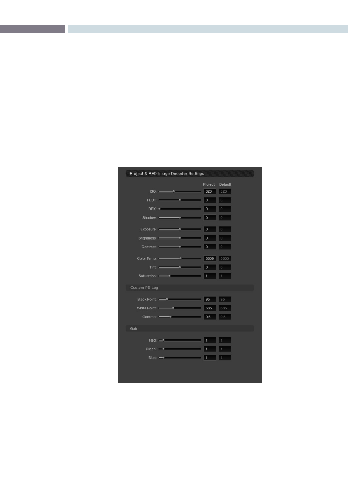
CHAPTER
CONFIGURATION
CONFIGURATION83
6
Project Image Decoder Settings
IfyouhavesettheDecodeClipsUsingparametertodecodeclipsusing‘Project’settings,thefollowing
controls become active. The RED default values are shown on the right hand column for your reference
andeachcontrolisadjustabletoestablishtheproject-baseddecodervalues.Justliketheotherproject
settings these can be set for each clip in the Color screen and also in the Media Pool.
Project Image Decoder Settings for RED Files

CONFIGURATION 84
ISO: Similar to exposure, this control adjusts gain from the black point to white in
a linear manner. 320 is the default.
FLUT: The Floating Point Look-Up Table controls operate within the new color
space to give cleaner and finer ISO and mid grey variation without
introducing clipping. Use in conjunction with ISO.
DRX: DRX is a dynamic range control that takes into account Color Temp (degrees
Kelvin) and Tint.
Shadow: Provides adjustments at the toe of the FLUT.
Exposure: Calibrated to replicate industry standard f-stops, Exposure increases or
decreases the image lightness and clips the data levels at each end.
Brightness: This also adjusts the image brightness by changing the black level, but unlike
Exposure, this control will compress the image at each end of its range.
Contrast: With the midtones maintained, the Contrast control adjusts the number of
discreet steps in the grey scale by changing the slope of the response curve.
Color Temp: Sometimes referred to as Kelvin, the color temperature adjusts the RGB matrix
to consider the blue/red ratio. Common values are 3200 for Tungsten lighting
and 5600 for daylight.
Tint: Use the tint control to adjust the yellow parameters of the RGB matrix. Ideal
to correct fluorescent or sodium vapor lamp problems.
Saturation: Color Saturation is varied from monochrome at 0 value, to the default (or
unity) of 1, up to very over saturated at 5.
Custom PDLog: The Custom PDLog parameter, Black Point, White Point and Gamma are
adjustable from their respective default values of 95, 685 and 0.6 gamma.
Gain: The Red, Green and Blue Gain controls adjust each color channels gain with
0 being the reference point. One (1) is unity gain and the maximum 10 is ten
times greater amplitude than unity.


7
Browse
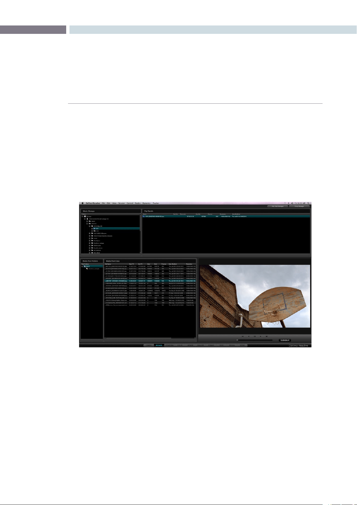
CHAPTER
BROWSE
BROWSE87
7
One of the fantastic features of DaVinci Resolve is that clips can be in any folder or volume that is
connected to the system.
Simply identify each clip (or folder of clips) and place it via a smart link into the active image storage
area called the media pool. The files are not physically moved or copied into the media pool. A virtual
path to each clip is created so it’s easy to identify all the clips needed for the project.
All clips that are to be graded must be in the Media Pool as they are used to form the Master Session
that is used to associate all color grading decisions within the DaVinci Resolve database. The Browse
screen gives you a number of ways to manage what clips are placed in the media pool and then to
configure them for grading, if required.
Browse
Browse
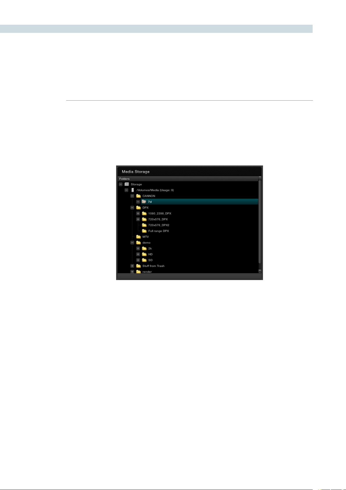
BROWSE 88
The upper left of the Browse screen displays all the media storage drives and folders within the storage
that you selected using the Preferences window. You can expand the folder structure to display folders
within folders. The sub folders or clips within folders will be visible on the Clip Details window directly to
the right of Media Storage display. Click on each folder to expand and view the clip metadata and the
actual content in the Viewer display. Or simply double click and the clip is then placed into the media
pool that will make it available for grading.
Media Storage
Folder Tree Expanded
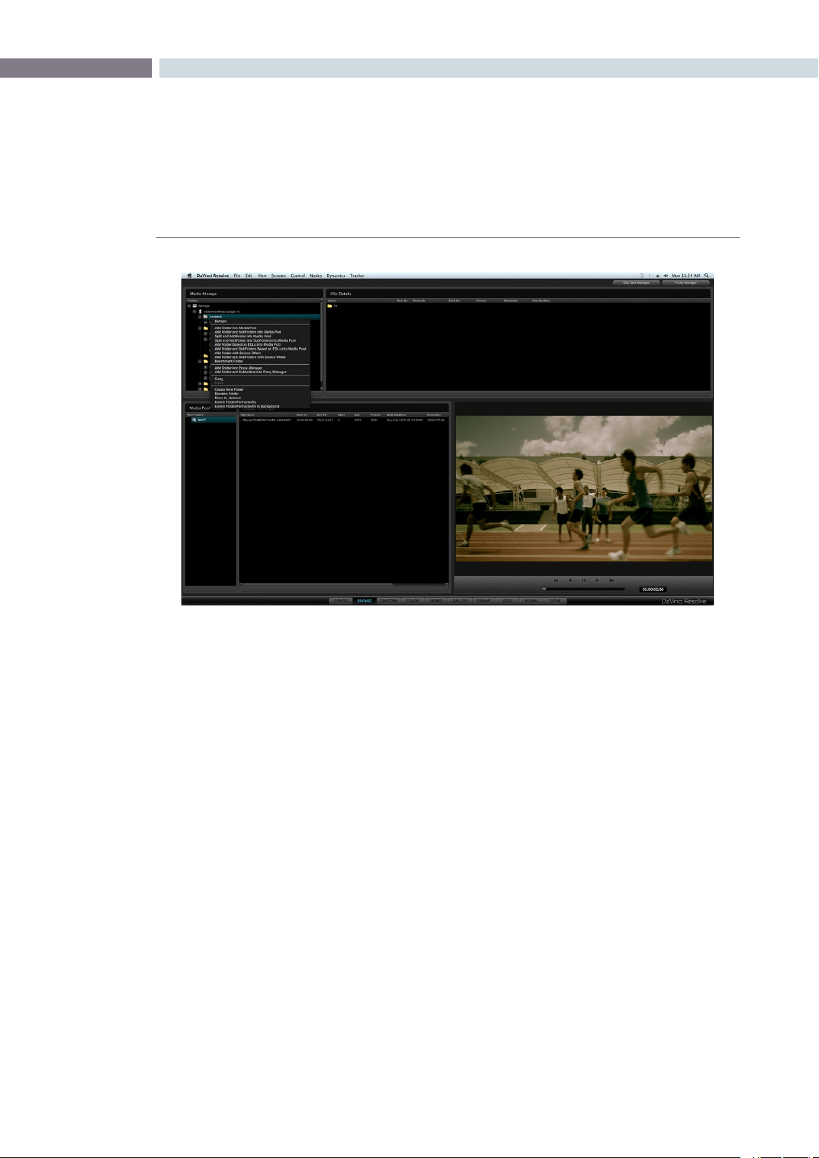
CHAPTER
BROWSE
BROWSE89
7
A right mouse click within the Media Storage display reveals a number of options.
Splitting Clips Based on an EDL
To split a clip based upon an EDL so that only the required material is placed within the Media Pool,
rightmouseclickonthedesiredcliporfolderandselect‘SplitandAddFolderandSub-Foldersinto
MediaPool’or‘SplitandAddfolderintotheMediaPool’fromthepop-upmenu.ThenfromFileBrowser
windowselectanEDLtouseforsplittingthesourcematerialandclickon‘Open’.Whenprompted,
select the handle size you need to be added to the clips: 5 frames, or 15 or 30, and ’Confirm’ to split the
clips. You will now see them in the Media Pool.
Browse Right Click over Folder Window
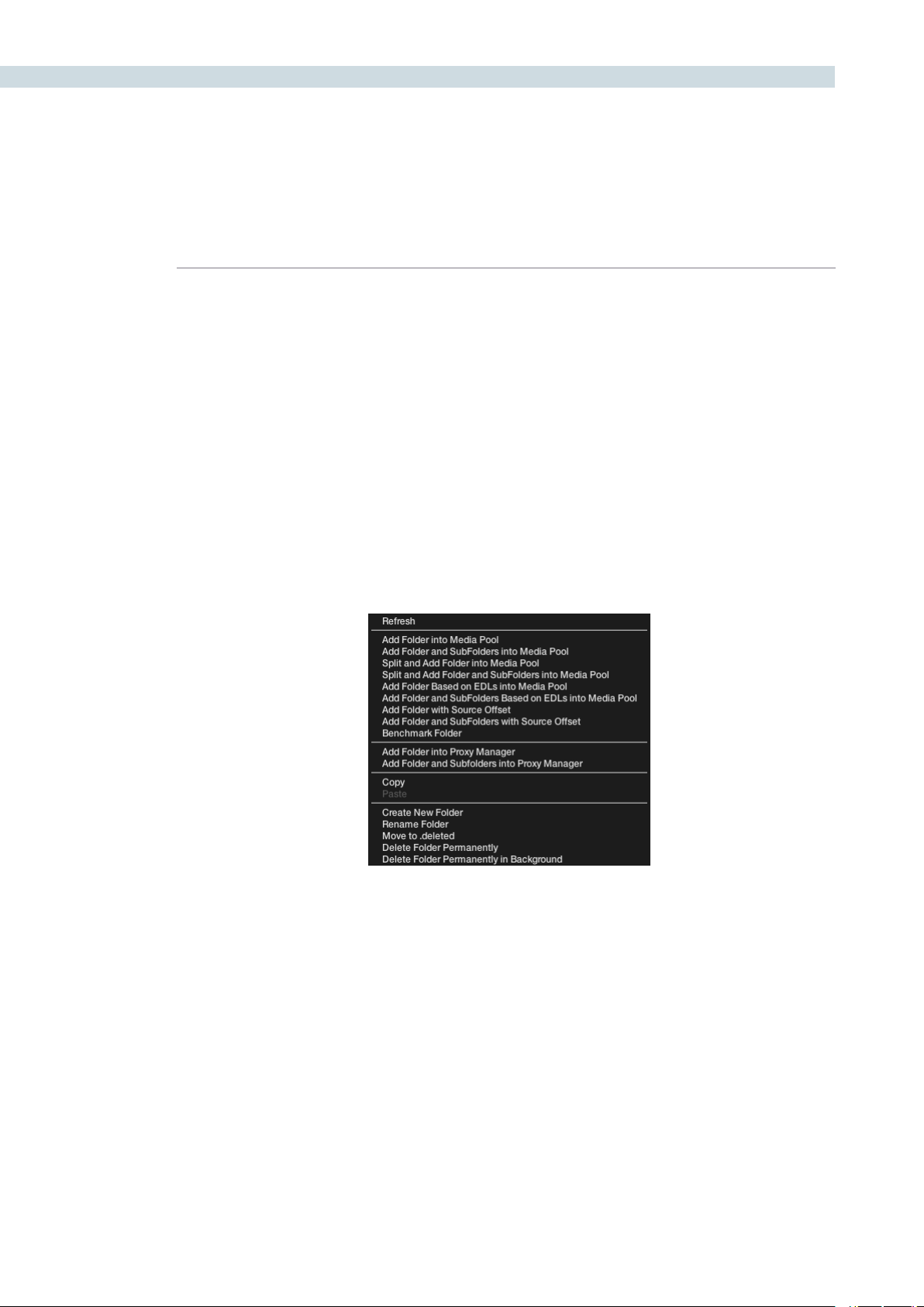
BROWSE 90
Add Material into the Media Pool Based on an EDL
Similartothe‘SplitandAdd’functionabove,youcanautomaticallyaddmaterialintotheMediaPool
based upon an EDL, however with this selection you can use multiple EDLs and many source folders.
Clickonthedirectorywheretherequiredmaterialislocatedandrightclicktoselect‘AddFolderand
SubFolders Based on EDLs’. Specify one or more EDLs. DaVinci Resolve searches the entire directory
tree starting from the selected directory for any clips referenced by source timecode and the reel ID in
the EDLs. Reel number sourcing is controlled in the same manner as Reel number conforming.
This automation does away with having to manually find and add clips to the Media Pool; a laborious
task for large conforms.
The EDLs will reference clips via their timecode and sometimes Reel name and path. It is these settings
and the conform frame rate that you made in the Configuration screen previously that are now utilized
to place images correctly into the Media Pool.
Close up view of Browse screen right mouse click over the folder window
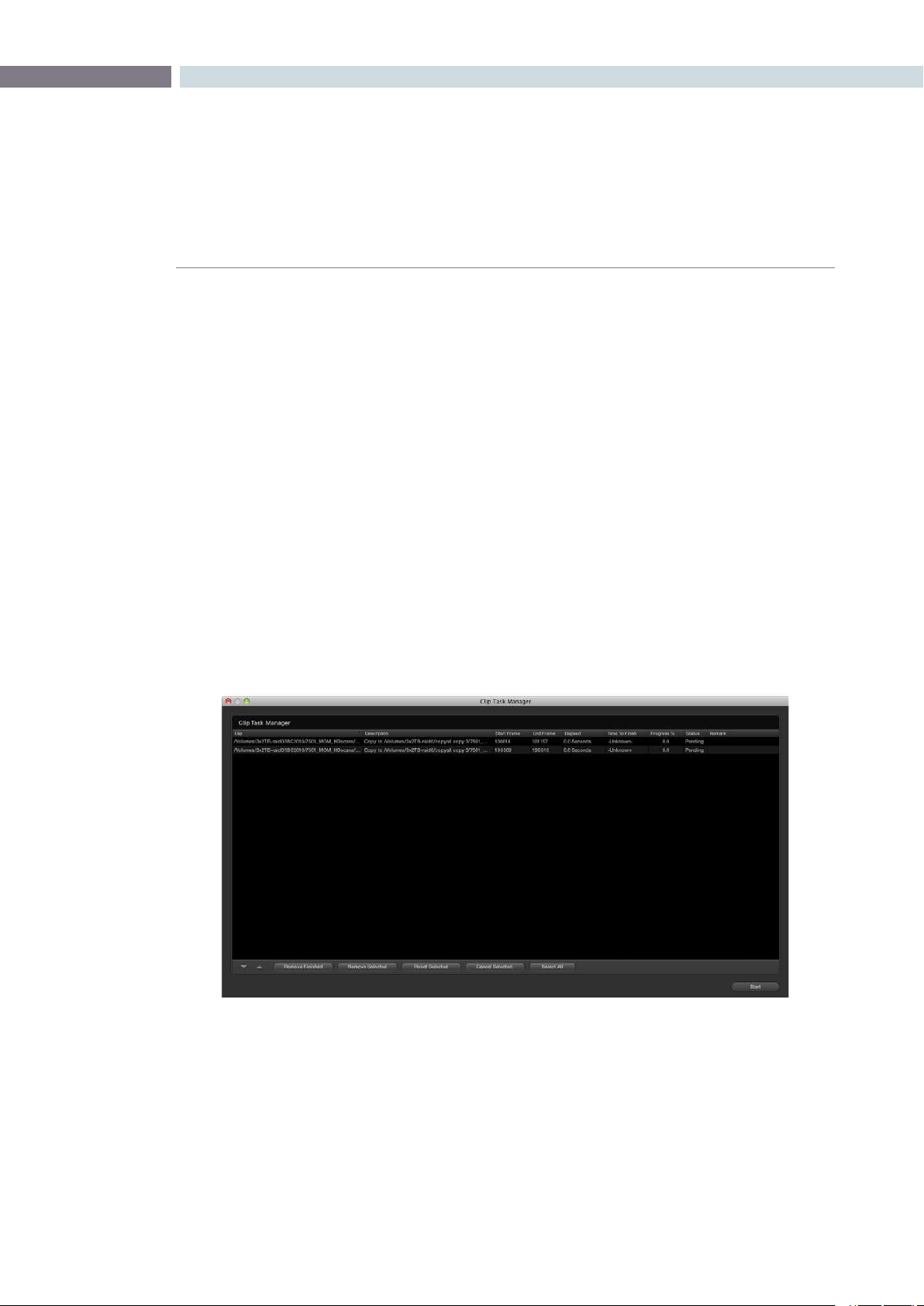
CHAPTER
BROWSE
BROWSE91
7
Offsetting the Source Timecode from a Clip
Sometimes source clips have an offset timecode due to a mistake made prior to introducing the images
toDaVinciResolve.Youcanselect‘AddFolderwithSourceOffset’andthenusedthepop-updialog
to enter the required frame count/timecode to offset the clips prior to loading into the Medial Pool.
HighlightthedesiredclipwithintheMediaPoolandrightmouseclick.Select‘OffsetSourceTimecode’
andthenthedesiredoffsettimecodevaluewithinthedisplay.Clickon‘Apply’toconrm.
Copy and Paste Function For Clips
You can create new folders, rename them, move folders and their clips to the deleted bin or permanently
delete the files with the Browse screen using the Clip Task Manager.
ToCopyaclip,rightmouseclickonthecliporfolderandselectthe‘Copy’function.Locatethedestination
folder,rightmouseclickselect‘Paste’.TheClipTaskManagerwillopenandallowyoutostartorprioritize
theCopyprocedure.Youmaystarttheprocessbyclickingonthe‘StartProcessing’buttonorCancel,
Remove or Move items within the display by using the editing tools on the right hand side of the display.
If changes are made in the folder structure, or files and folders are added to the storage you may need
torightclickontheMediaStoragedisplayto‘Refresh’thelist.
Clip Task Manager Dialog
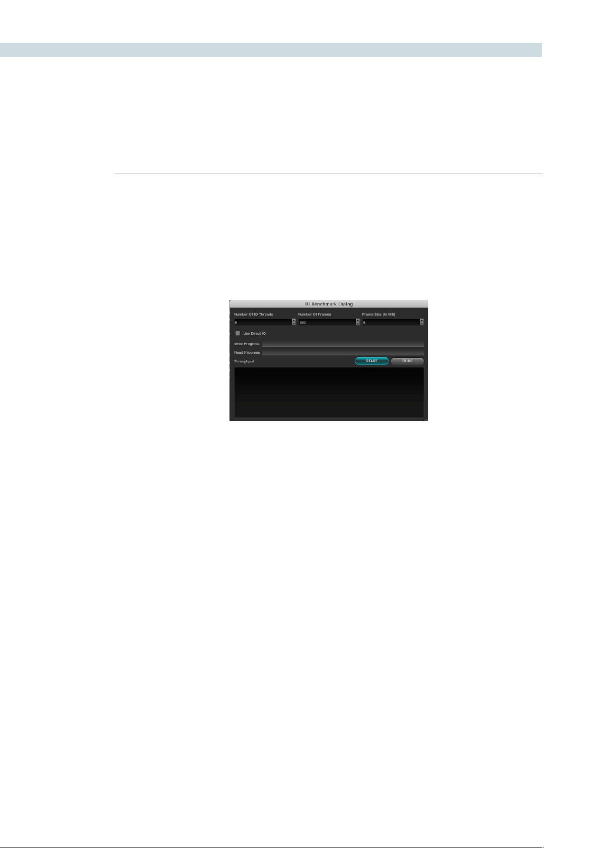
BROWSE 92
Disk Speed Benchmarking
OnLinuxsystems,ifyourightclickwithintheMediaStoragedisplay,youcanselectthe‘Benchmark
Folder’ tool that will benchmark the speed of the storage/SAN for either new or existing clips. This tool
may be used to ascertain whether fragmentation may be causing playback problems or if the storage
isfastenough.The‘UseDirectI/O’checkboxshouldbecheckedforCXFS/XFS/NFSlesystemsand
should not be checked for ADIC file systems.
The I/O Benchmark Dialog Display
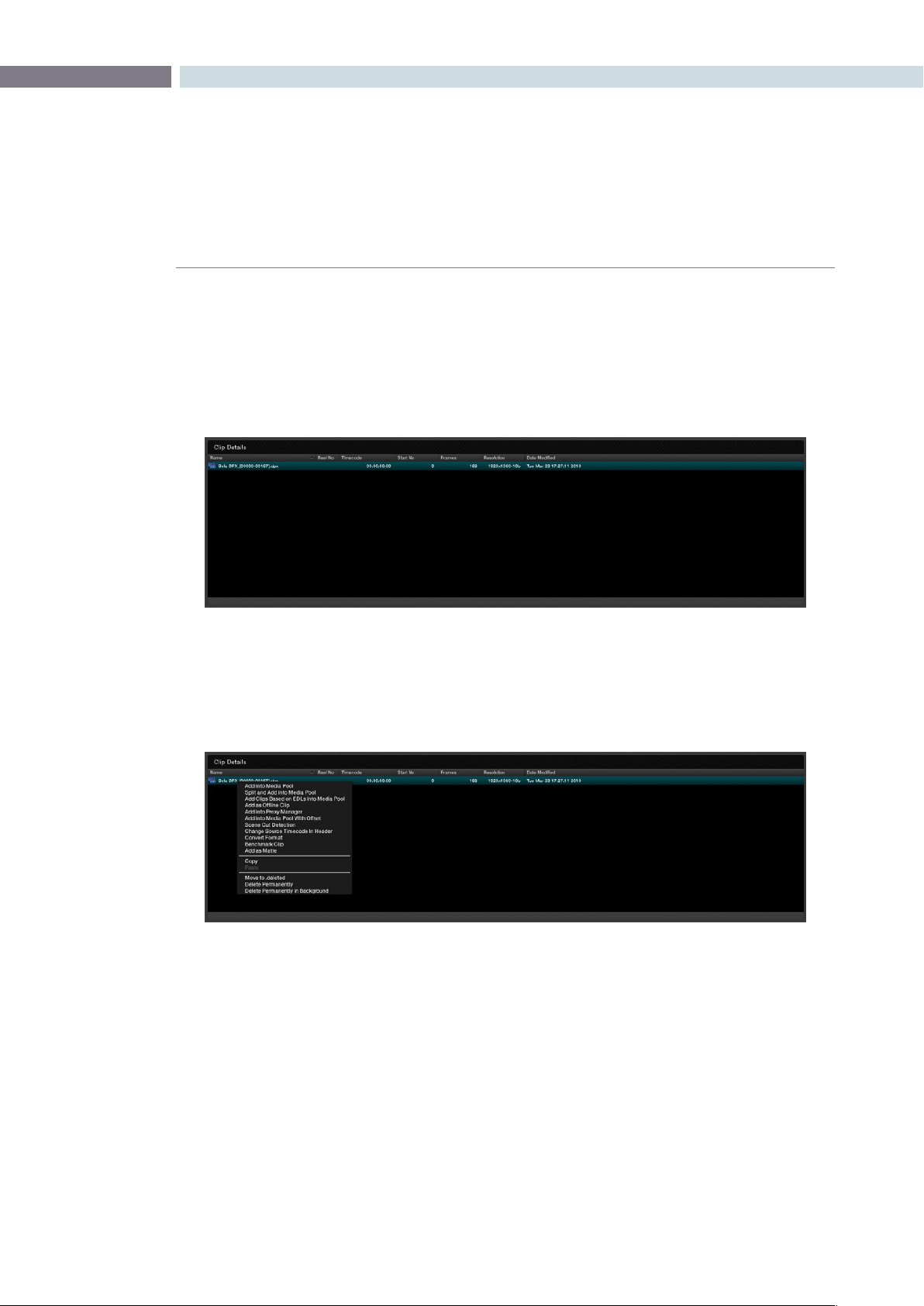
CHAPTER
BROWSE
BROWSE93
7
When you select any folder within the Media Storage window the folders and clips within that folder will
be visible in the Clip Details window. Clips will be identified by the film icon on the left-hand side of the
file name. When an individual clip is displayed in the Clip window you will also see metadata extracted
from the clip relating to timecode, the starting frame number and count, resolution, bit depth and the
date the file was modified. The file name will also include the post-fix identification of the file type. (DPX,
MOV, r3D, etc.).
The purpose of the Browse screen is to identify clips to place into the Media Pool. At any time a double
click on a clip will put it in the Media Pool. You may select multiple clips by holding down the shift key on
the keyboard and selecting the desired clips. While some of the options here are the same as the right
click over the Media Storage display, there are some extra functions found in Clip Details.
Clip Details
Clip Window
Clip Window Options
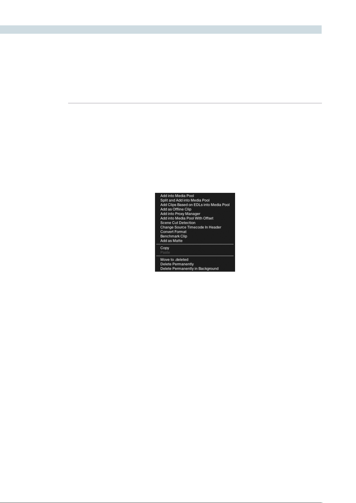
BROWSE 94
Add as an Offline Clip
Selecting a clip to add to the Media Pool as an offline clip makes an important distinction to these clips.
A DPX or MOV clip can be added to the Media Pool as an Offline clip and it will be designated by a
Magnifying Glass icon.
Identifying an Offline Clip, will allow DaVinci Resolve to treat this clip differently in the Conform screen
where you want to compare the high-resolution Online clips with the Offline, to establish that the EDL
matches the Offline clip.
Add into Proxy Manager
The Proxy Manager can also be accessed from the Media Pool and the Proxy Manager button; which is
at the top of the Browse screen. As this functionality is considerable, please review the operation details
later in this chapter.
Scene Cut Detector
All color corrections in the DaVinci Resolve database are related to individual source clips and their
timecode (and as selected file name and path). If you have imported a clip with numerous scene
changes and it does not have an EDL, the fastest way to split the clip is with the Scene Cut Detector.
By selecting this option the clip will be loaded into the Scene Cut Detector screen and be ready for
processing. Please review the Scene Cut Detector feature details in the Scene chapter.
Clip Window – right mouse click
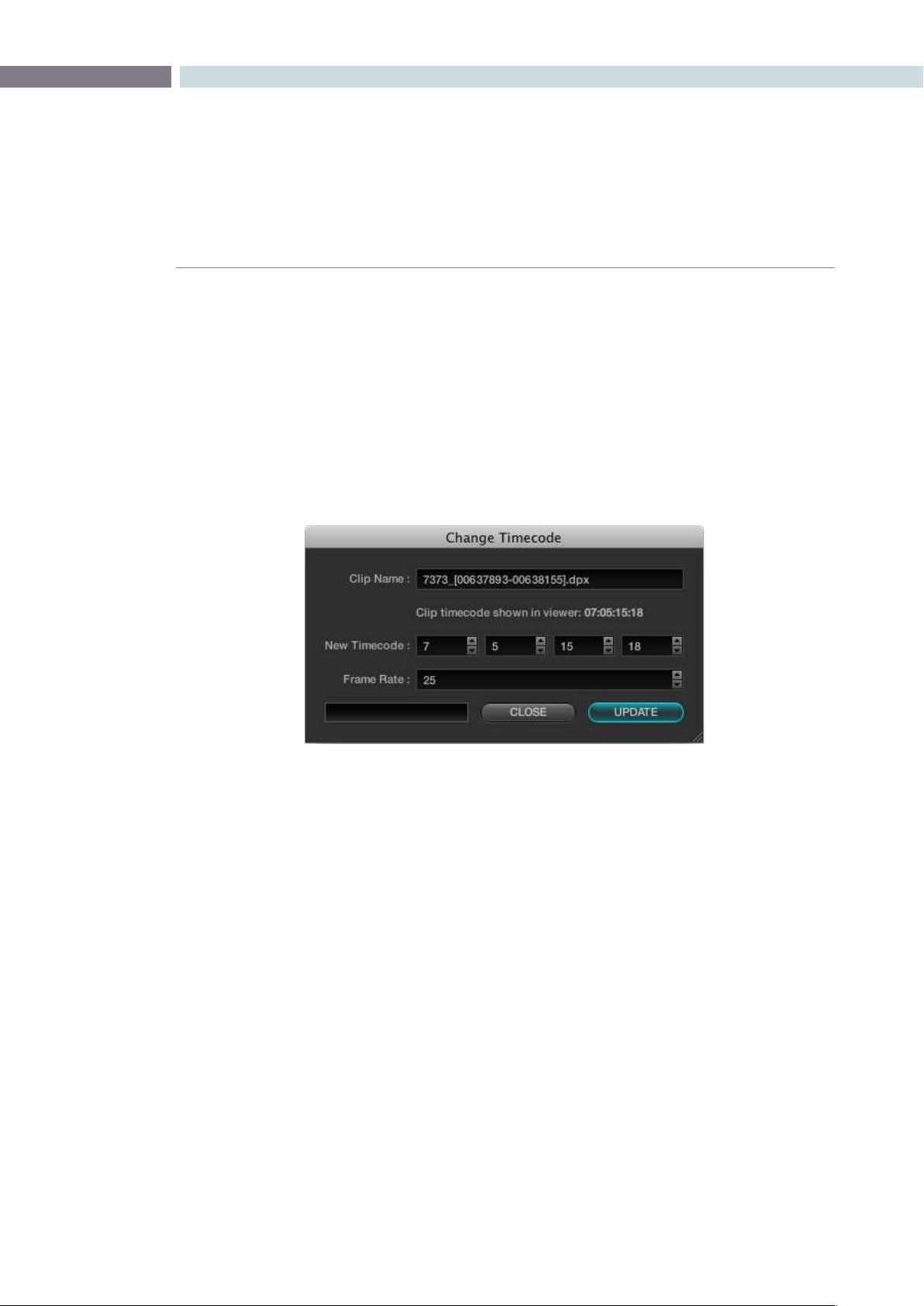
CHAPTER
BROWSE
BROWSE95
7
Changing the Source Timecode in Header
Previously, we discussed the option to add clips to the Media Pool with a frame offset. While that is
a commonly used feature, quite often you will find that your clips have no timecode or the wrong
timecode. DaVinci Resolve is capable of changing or assigning a different timecode to a clip. If there is
no timecode present in the clip header you can insert the timecode of your choice, or you can alter the
existing timecode to whatever number may be required.
Firstselectthele,thenrightmouseclickandchoosethe‘ChangeTimecode’option.Inthe‘Change
Timecode’ window select the new timecode for the first frame of the clip and also the frame rate, then
click‘Update.’
Change Timecode In Header
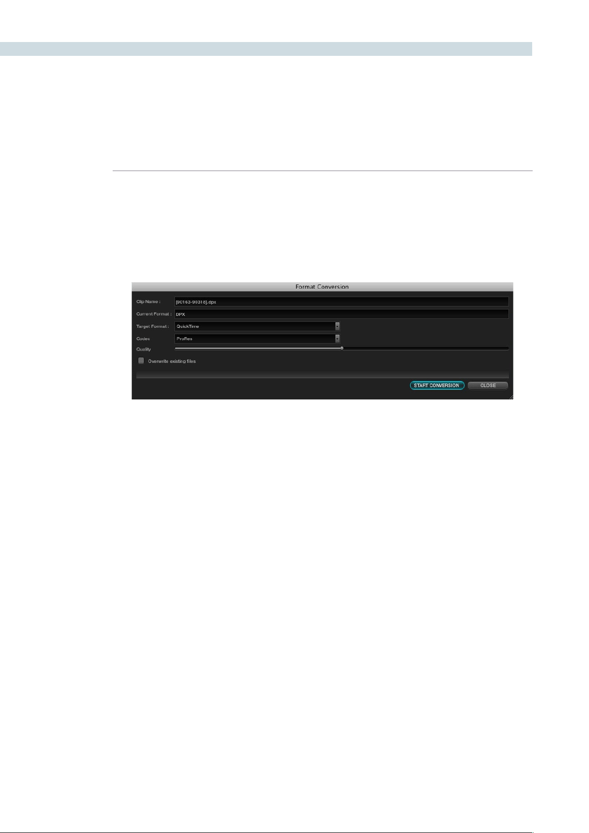
BROWSE 96
Converting a Clip to another File Format
You may find that clips come in a file format that DaVinci Resolve does not play natively in the timeline.
The Format Conversion pop-up allows you to change the file type. Simply select the clip within the Clip
Details display, right mouse click and select Format Conversion. In the new window select the Target
formatfortheclipand‘StartConversion.’
Add as Matte
IfyouhaveaclipfromaVFXsystemthereisoccasionallyanassociatedmattele.Byusingthe‘Add
as Matte’ you place the file in the Media Pool with the correct identification, shown as a Mask icon so
that DaVinci Resolve can use the file as a Matte. After you have placed the main image clip into the
Media Pool, highlight the clip. Then find the matte in the Clip Details display, right click on that matte
andselect‘AddasMatte.’IntheMediaPool,themainclipwillhaveacyanboxjustbeforetheclipname
and if you double click the main clip, the associated matte will be shown with the Mask icon; it is linked
to the main clip.
Format Conversion
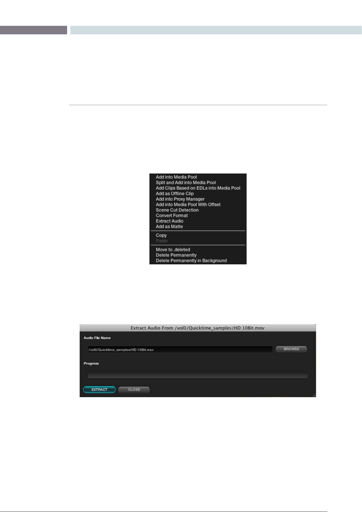
CHAPTER
BROWSE
BROWSE97
7
Extract Audio from QuickTime
DaVinci Resolve is a color correction and enhancement system, but it also offers synced audio playback
of .wav or AIFF audio files. To extract audio from a QuickTime file into a separate .wav file for synced
playback,rightclickonanyQuickTimeleinthebrowsescreenandselect‘ExtractAudio’tobringup
the Audio Extraction window.
Specifywheretheextractedaudioleshouldbestoredandthenselectthe‘Extract’buttontostart
audio extraction. If the QuickTime audio track is encoded with incompatible audio codec, an error
message box will be displayed to notify the user. After audio extraction is complete, you can attach the
extracted .wav to a session in the Conform screen.
Clip window – right mouse click over QT file
Audio Extraction from QT files.
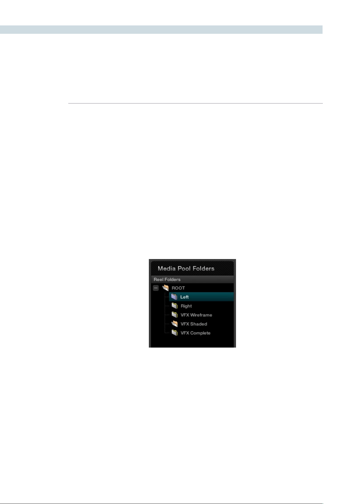
BROWSE 98
Media Pool Folders
As previously noted, all clips that are destined for color grading must be in the Media Pool, so all grading
metadata can be associated to the clips with clip timecode on the frame reference. The Media Pool
display is in two parts: Folders, which actually is the top level of the Media Pool structure, and Clips.
The Media Pool Folders display allows you to place clips into the Media Pool in one or many layers of
virtual folders. These virtual folders could be associated with the clip’s reel names or numbers, segmented
by images for the trailer, feature or video press kit, used to manage the workflow transition from VFX
wireframes to VFX shaded and then fully rendered VFX images, or in the case of a Stereoscopic project,
separated into left and right eyes.
Addingfoldersiseasy.Rightmouseclickwithinthedisplayandselect‘AddNewFolder’or‘Rename
Folder’ to change the name of an existing folder. When you have your folders set up, just select the
specific folder to which you wish to add clips.
Another key benefit of separating source files into virtual folders within the Media Pool will be seen later
when we are on the Conform screen. We can apply an EDL to all clips in the Media Pool to create a new
timeline (Session) or to only those clips in one of the virtual folders.
The Media Pool
Media Pool Folder Display
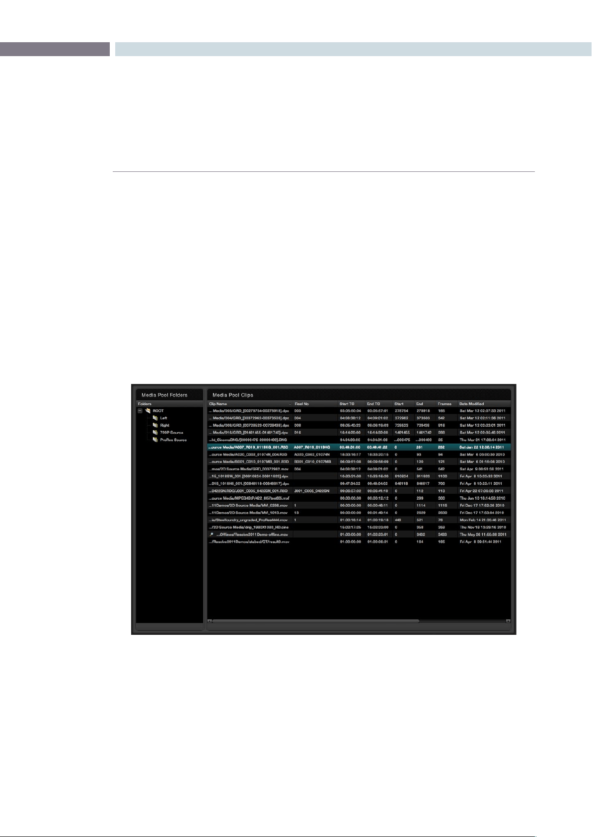
CHAPTER
BROWSE
BROWSE99
7
Media Pool Clips
The Media Pool Clips display shows each clip with its name, reel number, start and end timecode, start
and end frame number, actual number of frames, the date the file was modified, its resolution and bit
depth, and the file name itself, identifies the type of file. The last two columns are PAR (Pixel Aspect
Ratio) and Start KeyKode. Not all files are from film scans, and even then not all have KeyKode, so this
column may be blank.
You will also notice a column labeled Usage. This column will display how many times a clip is used
within the EDL. After you have loaded the EDL on the Conform screen, you must right click over this
windowandselect‘UpdateInformation’fortheUsageinformationtobevalid.Whilethismayseem
redundant, it does allow you to verify that all the clips in the Media Pool, and thus, the master Session
timeline, actually need to be there and can therefore, reduce the render and playout time if you are
renderingallthesourceclips.Justasthereareright-clickpop-upsontheotherwindows,theMediaPool
has its own, shown on the next page.
Media Pool
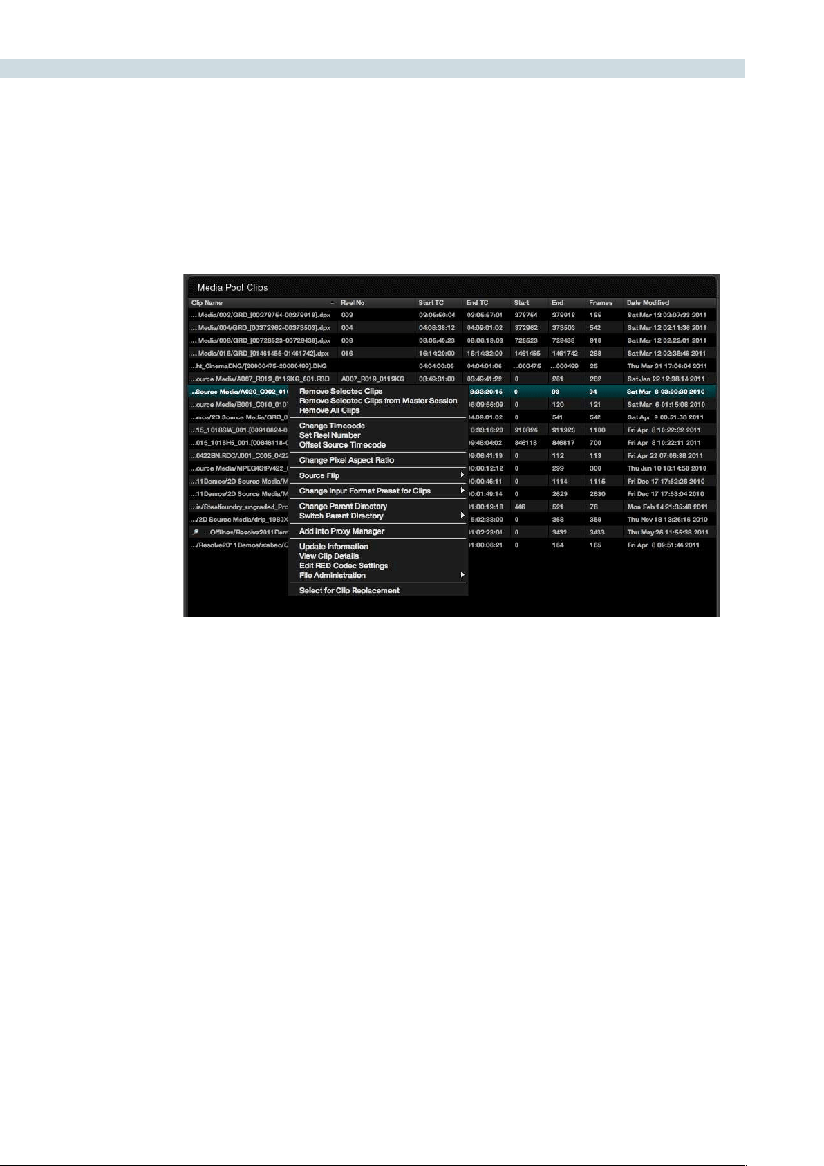
BROWSE 100
Remove selected Clips
This action will remove these clips from the Media Pool. The Master Session Timeline will display the clip
position and duration, but with a blue cross over the clip indicating that the clip is no longer in the Media
Pool. This can be helpful when changing source images with the same timecode.
Remove from Master Session
This operation will remove the clips from the Media Pool and also remove them from the Master Session.
Remove all Clips
This operation will remove all of the clips from the Media Pool but not from the Master Session.
Media Pool – right click options
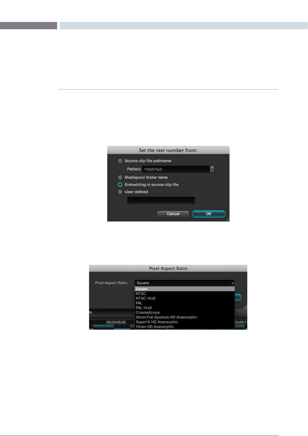
CHAPTER
BROWSE
BROWSE101
7
Set Reel Number
Justasweselectedonthecongurationpage,projecttab,conformtimelinesection,youcanselector
change the way Resolve defines the clip reel number in the media pool. There is one additional option
here, to have a user defined reel number, which is quite helpful when the automatic conforming of clips
is not possible or a reel name in the file is incorrect.
Change Pixel Aspect Ratio
You can change this for any clip with the right-click option, then select the appropriate PAR.
Source Flip
DaVinci Resolve supports the horizontal and vertical image flip camera metadata for r3d clips, which is
very helpful for stereoscopic 3D projects to flip the eye that is shot through the mirror rig. This technical
flip can be manually set, or overridden, using the Source Flip option in the Media Pool and is different to
the creative HFlip and VFlip colorists set in the Format screen.
Change Pixel Aspect Ratio
Set Reel Number
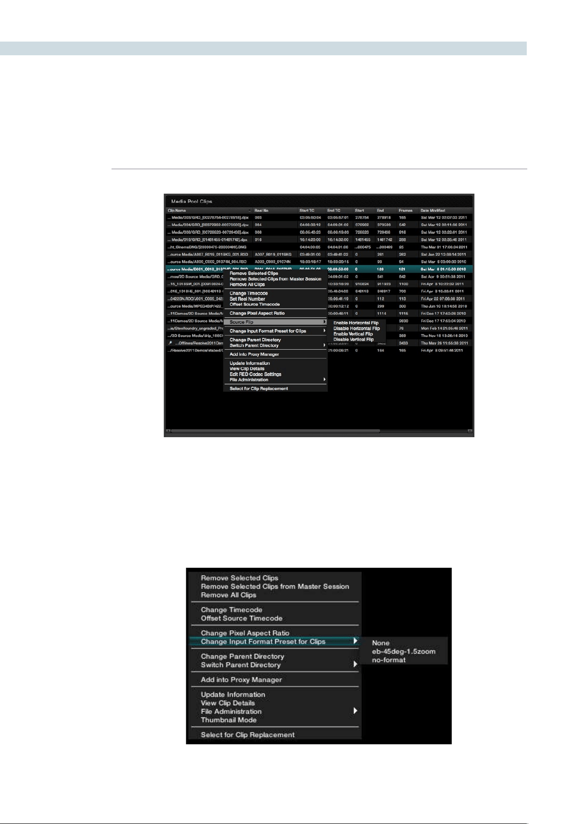
BROWSE 102
Change Input Format Preset
The Media Pool right-click allows the selection of the Input Format Preset to be changed. On the Config
screen tab you can set the default Input and Output format presets. Within the Media Pool you can set
the Input format for each specific clip. Place your mouse over the clip and right click to show the options
andthenselect‘ChangeInputFormatPresetforClips’andselectfromthepresetformatsyoumadein
the Format Screen.
Select to Enable Flip
Change Input Format Preset
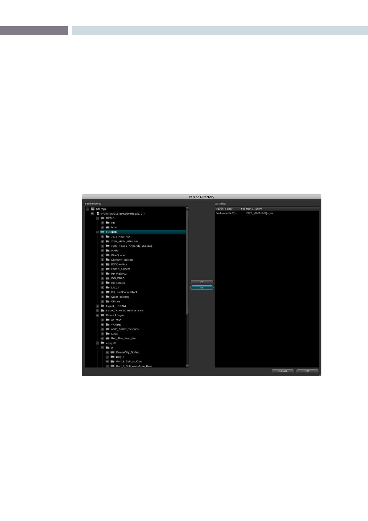
CHAPTER
BROWSE
BROWSE103
7
Change Parent Directory
Whenthelocationofthesourceclipshaschanged,usethe‘ChangeParentDirectory’optiontorelink
to the new clip location. This will automatically search for the new parent location of the clips that have
been placed into the Media Pool. Highlight one or more clips within the Media Pool and right click to
select‘ChangeParentDirectoryofClips.’Awindowwilldisplaytheoriginalpathforthematerialandlet
you enter or browse to the new path. Select the Change button to start the relink. If there is no match
found, no change will occur.
Customize Parent Directories Dialog
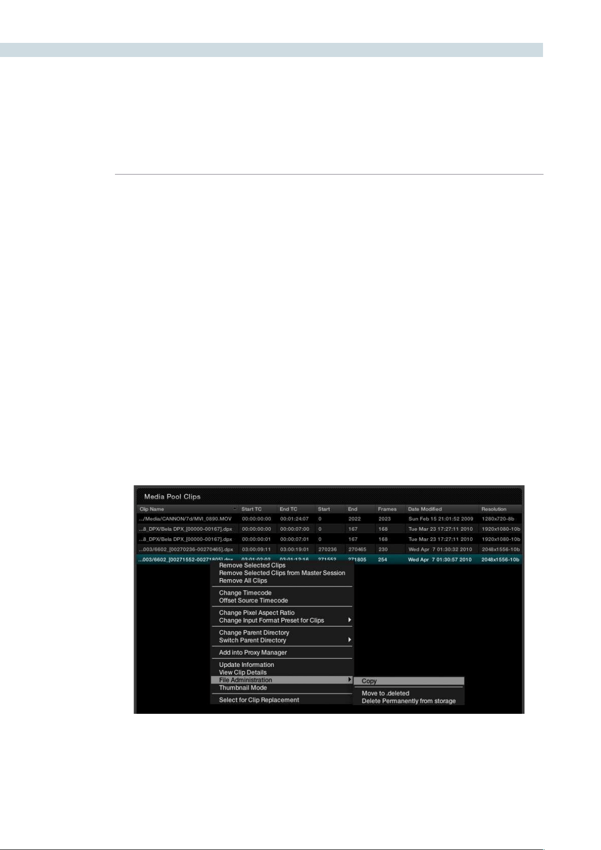
BROWSE 104
Switch Parent Directory
With a pre-conform workflow, there are often different versions of edits that are in separate folders.
DaVinci Resolve allows easy toggling of different versions of conform using switchable parent directories
from the right-click menu in the Media Pool. In the Parent Directory window, browse to the pre-conform
directory folder and click the right arrow button to add the selected directory into the Parent Directory
List. Click the left arrow button to remove the selected directories from the directory list. Confirm your
selectionwiththe‘OK’button.
The .deleted Folder
Tomoveacliptothe.deletedfolder,rightmouseclickontheleandselecttheoption‘Moveto.deleted’
from the File Administration menu. A prompt will ask you to confirm or to Cancel the operation.
If you wish to remove a file or files from the .deleted folder, open the .deleted folder and highlight the
clip.Rightmouseclickandselect‘RestoreClip.’
Topermanentlydeleteacliporfolder,select‘DeletePermanently’whenrightmouseclickinguponthe
clip within the .deleted folder or within any of the other files or folders.
You may select the option of deleting material in the background without the user interface being locked
during the delete process. During this operation the clips or folders will be deleted in the background
and a prompt will appear to inform you when the process is complete.
File Administration within the Media Pool
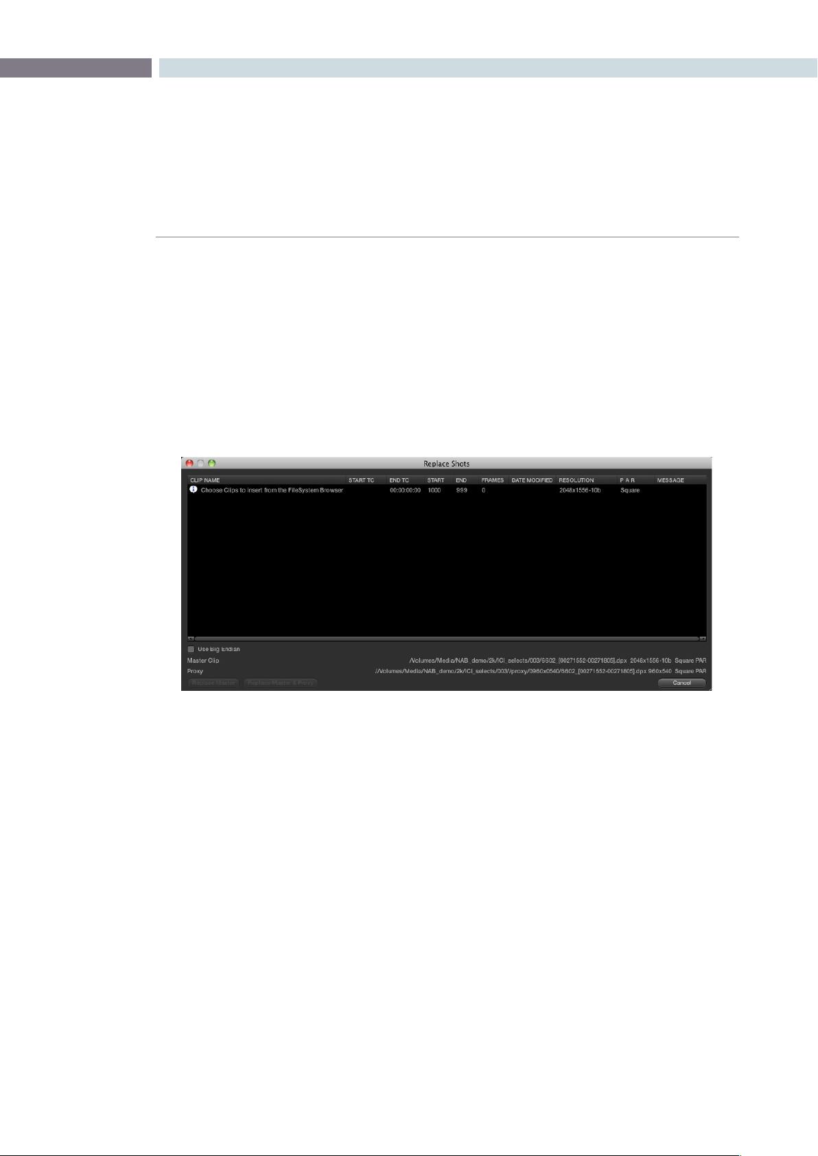
CHAPTER
BROWSE
BROWSE105
7
Clip Replacement and Automatic Proxy Generation
To replace sections of a master clip with frames from another location or to automatically generate
proxies for the selected frames, use the Replace Shots tool. This option comes in handy when you
modify a subset of a clip using different tools and want to merge their modifications in the current clip.
First,rightmouseclickonthemasterclipwithintheMediaPoolandselect‘SelectforClipReplacement.’
Next,buildareplacementshotlistbyrightmouseclickingontherequiredclipsandselectthe‘Add
toReplaceList’option.Then,eitherselectthe‘ReplaceMaster’buttonorthe‘ReplaceMasterand
Proxy’ button.
The Replace Shot Display
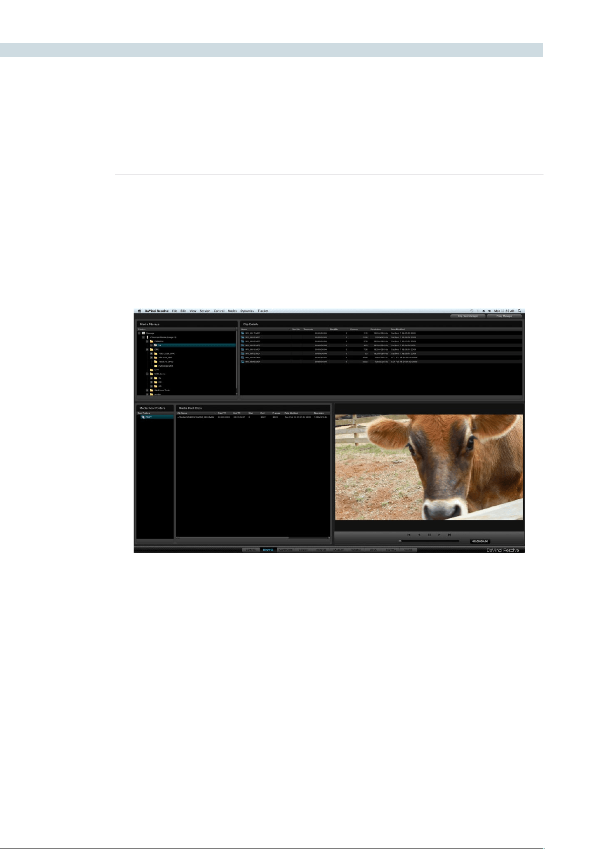
BROWSE 106
The Viewer window is used to preview clips located either in the storage area or within the Media
Pool. The bottom of the window has transport controls for Stop, Forward, Reverse, Fast Forward and
Fast Reverse. Below the transport controls is a slider bar that can be dragged with the mouse to scroll
through the clip area. This slider will display the relative position of the frame within the full clip.
The clip’s timecode is also displayed. If you right mouse click on the image you can superimpose
KeyKode information if it is in the file.
Viewer Window
Viewer Window
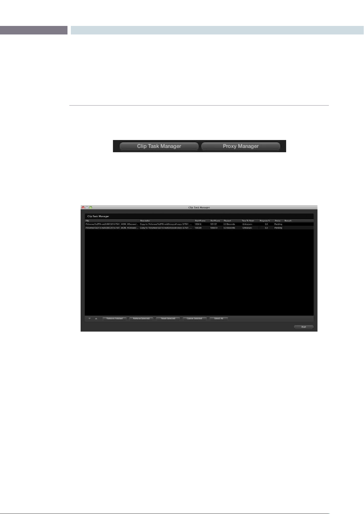
CHAPTER
BROWSE
BROWSE107
7
Located at the top of the Browse display are two buttons used to select either the Clip Task Manager
or the Proxy Manager.
Clip Task Manager
The Clip Task Manager can be selected from the Browse screen buttons, or via the Proxy generation
config, or if a clip Copy and Paste operation is initiated. To close the Clip Task Manager display, simply
clickonthe‘CloseDialog’button.
Browse Screen Buttons
Clip task manager
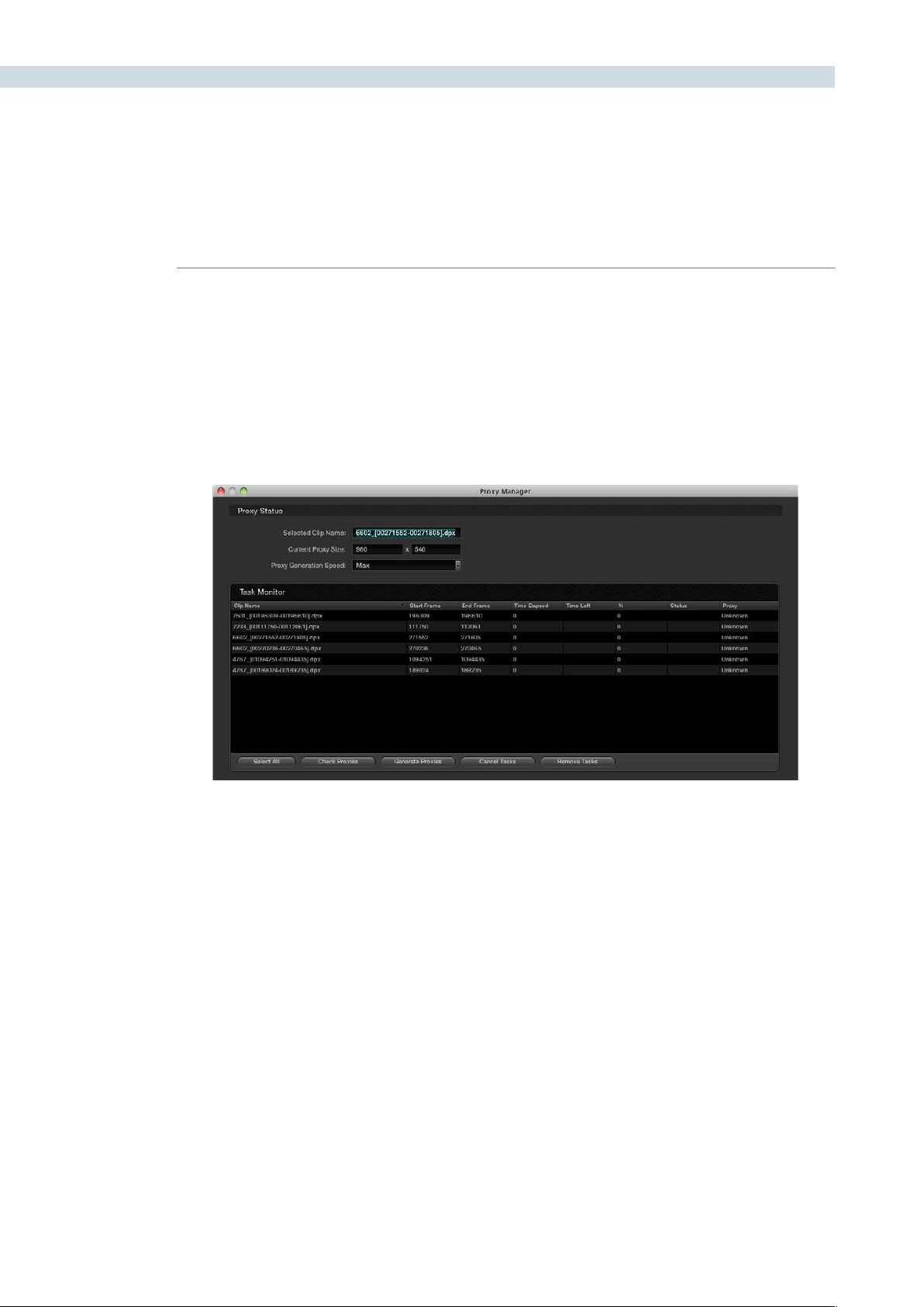
BROWSE 108
Proxy Manager
The Proxy Manager lets you control the proxy generation process. To send a clip to the Proxy Manager
rightclickontheselectionfromtheFolderandClipWindows,orMediaPool,thenselect‘AddIntoProxy
Manager.’ To add the entire contents of a folder into the Proxy Manager, right click within the Media
storagesectionandselect‘AddFolderIntoProxyManager’fromtheoptions.
If you prefer, proxies may be pre-generated before a session. If generating proxies, a half or quarter of
the resolution is recommended for maximum speed.
TheProxymodemaybeactivatedbycheckingthe‘UseRealTimeProxies’optionthatislocatedinthe
Congurationscreenorbypressingthe‘Proxy’buttonontheResolvecontrolpanel.Theuseofproxies
is generally required when a highly complex color correction causes the system to run slightly slower
than real time. If there are pre-generated proxies, DaVinci Resolve will use them automatically, otherwise,
DaVinci Resolve will generate them on the fly.
TheProxyManagerdisplayhasvebuttonstomanagethegenerationofproxies.‘CheckProxies’looks
fortheexistenceofthegeneratedproxies.‘CheckSelectedProxies’willcheckfortheexistenceof
onlytheselectedles.‘GenerateAllProxies’willgenerateproxiesforallleswithintheTaskManager
windowand‘GenerateProxies’willgenerateproxiesfortheleswithintheTaskManagerthathavebeen
highlighted.The‘CancelTasks’buttonwillcancelallproxy-generatingprocesses,and‘CancelSelected
Tasks’willcancelonlytheselectedproxygeneration.‘RemoveTasks’willclearallclipsthatarepresent
within the Task Manager window.
JustasDaVinciResolveallowsthrottlingofrenderspeed,youcanthrottleproxygenerationspeeds.
This enables you to control SAN bandwidth utilization and select the speed of proxy generation your
storage system can manage. Located at the top of the Proxy Manager window, the Proxy Status shows
the name of the selected clip. Also shown, is the current proxy width and height.
Proxy Manager Display


8
Conform
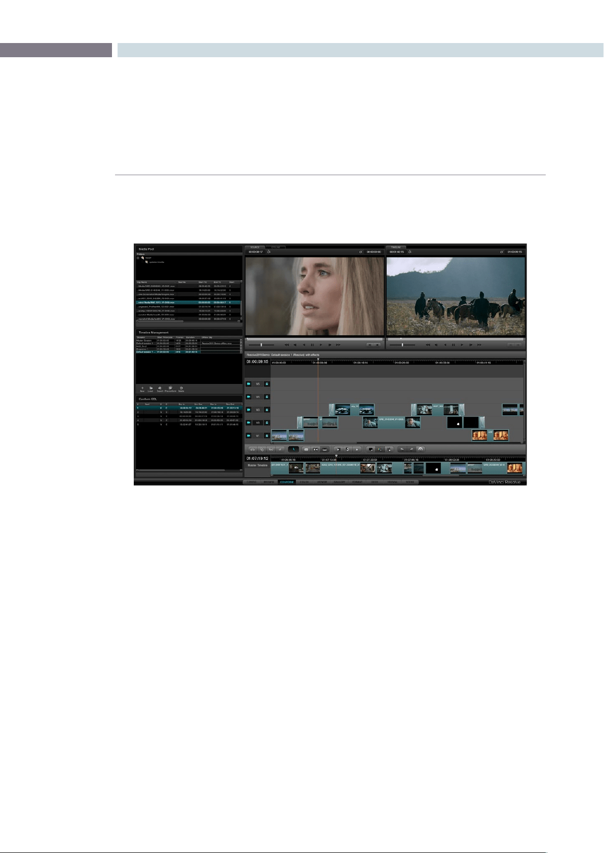
CHAPTER
CONFORM
CONFORM111
8
Overview of the Conform Page
The Conform page is where you import edited projects from other applications via EDL, AAF, or XML.
This edited project data is used to arrange the clips in the Media Pool into the session that constitutes
the program you’re grading.
While some project formats make it possible to import a project’s referenced media at the same time
as its edit data, it’s important to understand that the Resolve database organizes an edited timeline and
the media it uses separately. This makes it possible to import multiple versions of a project using several
EDL, AAF, or XML files, with the result being a Resolve project with multiple timelines (referred to as
sessions), each having a differently edited arrangement of the same media.
Additionally, in Source mode the Conform page enables you to perform simple editorial functions that
are useful for making the small alterations that grading sometimes requires, such as replacing media,
splitting clips, adding transitions, or changing the composite modes of superimposed clips.
Finally, in Offline mode the Conform page can be used for loading an offline clip, which is useful both for
confirming that the imported project in fact matches the original project as output from the NLE, and
for comparing the new color adjustments and geometric transforms that you’re making against offline
effects that were made during editorial.
This chapter covers different ways of working within the Conform page, including workflows for project
import, editorial, and offline comparison. Keep in mind that many of the commands in the conform screen
are found within the contextual menus that appear when you Right-click various items and objects.
Tip: You can resize the height of the Media Pool, Timeline Managment, and Conform EDL lists by
dragging the border between them up and down.
An imported project shown in the Conform page. Its media appears in the Media Pool, the edit appears as a
session in the Timeline Management list, and the edited project appears in the Timeline.

CONFORM 112
Controls of the Conform Page
The conform page is divided into six regions, all of which help you to manage the multiple forms of
data within a particular project. In DaVinci Resolve, Projects contain one or more sessions organized in
the Timeline Management list but displayed in the Timeline. They are divided into individual edit events
shown in the Conform EDL list. Each event references a particular clip that’s shown in the Media Pool.
This database structure is what lets you manage one set of grades that can be used by multiple sessions,
each of which is a different version of the edit.
By default, grades are associated with the timecode of the source clip they’re applied to. When a new
session rearranges clips into a different order, grades automatically follow the clips, so each new session
inherits the grades you created in other sessions.
Note: This relationship can be suspended so that different sessions can have independent sets of
grades using Local versions. However, by default, a clip’s grades are shared by every instance of that clip
in all sessions using Remote versions.
The Hierarchy of the DaVinci Resolve Database
To provide a better understanding of how data is managed within each project, here is the
hierarchy of how all information is stored in the database:
Database>Users>Projects>Sessions>Clips>Timecode>Versions>PTZR/Grade
In plain English, each database is organized into a number of users. Each user is a container
that holds one or more projects that are unique to that user. Each project contains one or
more sessions, and each session contains one or more clips. Each clip contains a range of
timecode and a reel, each of which points to three independent sets of adjustment data:
Source settings (such as R3D or Alexa metadata), and versions that contain pan/tilt/zoom/
rotate/3D(PTZR)settings,andgrades,whichareappliedtoeachclipinthatorder.
The Media Pool
Miniature versions of the Media Pool folders and clips lists found on the Browse page are also available
on the Conform page. Using it, you can troubleshoot the correspondence of a clip in the timeline with the
source media it references, edit new clips into a Timeline, replace a clip in the Timeline with another clip
in the Media Pool, or load an offline-identified media file of a program to compare it against your project.
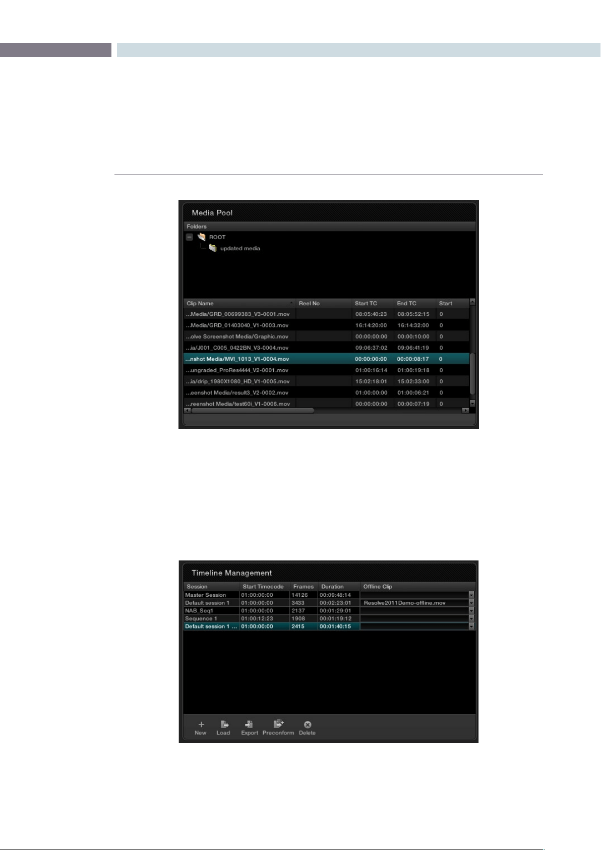
CHAPTER
CONFORM
CONFORM113
8
Right-clicking a folder or anywhere within the clip list shows every menu option that’s available from the
Media Pool in the Browse page. For more information, see the Browse chapter.
The Timeline Management List
This list has all of the commands that are available for creating a project’s master session, creating blank
sessions, importing EDL, AAF, or XML projects as sessions, and managing these sessions.
The Media Pool in the Conform page
The Timeline Management list in the Conform page

CONFORM 114
Every EDL, AAF, or XML file you import appears as a new session in this list, and you can have as many
sessions as you like within a single project. However, since each session must reference clips in that
project’s media pool, multiple sessions are most often used for multiple edited versions of a particular
program or reel. Additionally, multiple sessions can also be used to store differently graded versions of
a particular session.
Note: The first session that is created, either by you or automatically, and the first item in the Timeline
Management list is always the Master Session.
There is no right-click menu available in the Timeline Management list. However, there are five buttons
running along the bottom:
New: Click to create either the Master Session, which is always the first
session that’s created, or a new blank session once the Master
Session has already been created.
Load: Click to import an EDL, AAF, or XML project file from
another application.
Export: Click to export the selected session as an XML file that can be
opened in Final Cut Pro.
Preconform: Click to “notch” or split a flattened master media file into
individual clips in the using a matching EDL.
Delete: Click to delete the selected session. A dialog appears giving you
the option to save the stills for that Session, in the event you
want to keep them for later reference.
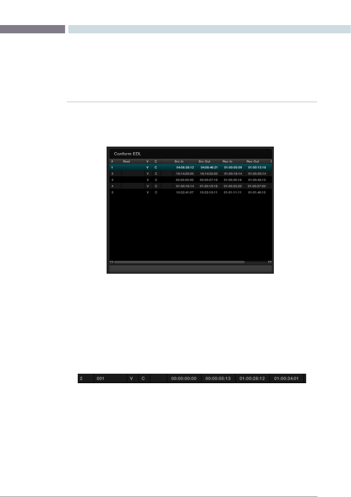
CHAPTER
CONFORM
CONFORM115
8
The Conform EDL List
The Conform EDL list shows an EDL-style list view of all the edit events within a particular session.
Whichever session is selected in the Timeline Management list displays its events here.
Each clip and transition is shown as an individual event, each of which contains multiple columns of
information. If you re-edit a session, your changes are also reflected in this list.
Note: There is no contextual menu available in the Conform EDL list.
Whenever you move the Timeline playhead to intersect a clip, the Conform EDL list updates to show
only the clips on the video track the intersecting clip is on, and that clip’s event is highlighted in the
Conform EDL list. This makes it easy to see the correspondence between a clip in the Timeline and its
event, which is helpful when troubleshooting problem sessions.
Each event contains the following columns of information:
#: The event number, which corresponds to the clip number shown
in the Thumbnail Timeline of the Color page
Reel: The reel name of the corresponding clip
V: Video event
The Conform EDL list in the Conform page
An individual event in the Timeline Management list
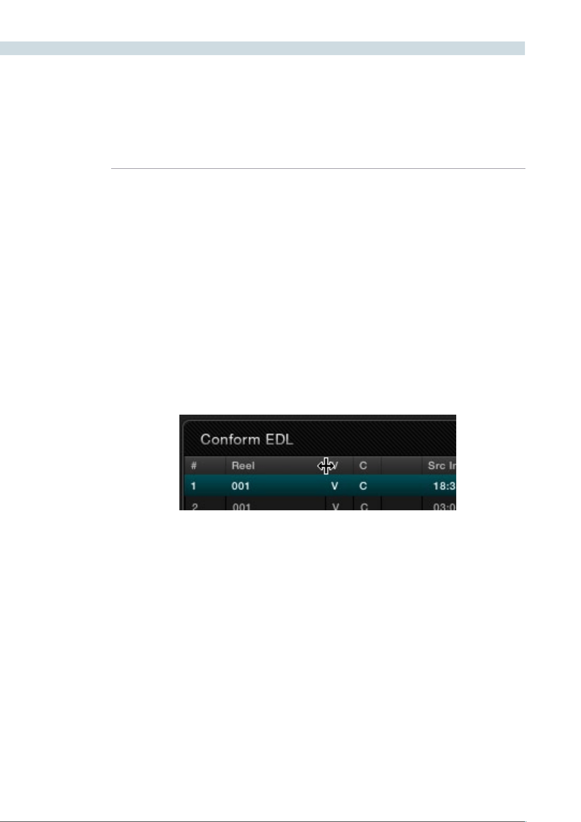
CONFORM 116
C: The event type (C for cut, D for dissolve or transition)
Blank: A number showing the duration of a transition in frames.
Src In/Src Out: The Source In and Source Out timecode indicating the
originating timecode referenced by that clip
Rec In/Rec Out: Record In and Record Out timecode indicating that clip’s
position in the Timeline.
Comments: Whatever comments were present in the EDL that was
imported, typically clip names exported from the original NLE to
be used as Reel Names in RED workflows.
There are two ways of customizing the Conform EDL list.
To resize any column of the Conform EDL list:
•Moveyourpointeroverthedividerbetweenanytwocolumnsanddragtotheright
when the horizontal resize cursor appears.
The column widens, letting you see its full contents.
Resizing a column in the Conform EDL list
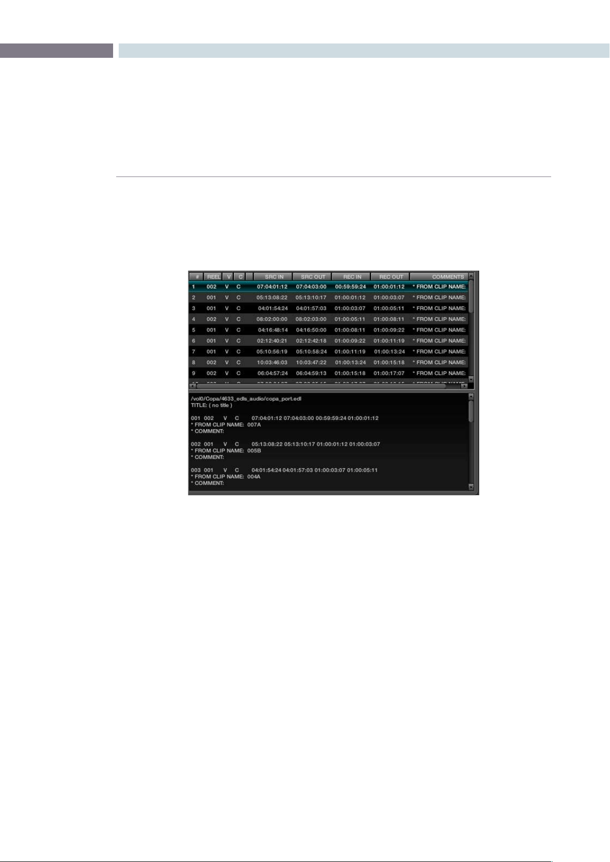
CHAPTER
CONFORM
CONFORM117
8
To display the originally imported EDL:
•PlaceyourpointeroverthebottomborderoftheConformEDLlistsothatitturns
into a vertical resize cursor, and drag the bottom border up to reveal a split-window
showing the text of the original EDL that was imported.
Note: If the session was imported via an AAF or XML file, nothing will appear in this split view.
The Source, Offline, and Timeline Tabs
The Source and Offline tabs let you switch between two modes of operation in the Conform page.
Open the Source tab to view individual clips from the Media Pool in preparation for editing. Open the
Offline tab to load an offline-identified clip of a project that you can compare with the Timeline.
Meanwhile, the Timeline tab shows the frame at the position of the playhead of the currently open session.
EDL Display above and raw EDL text below
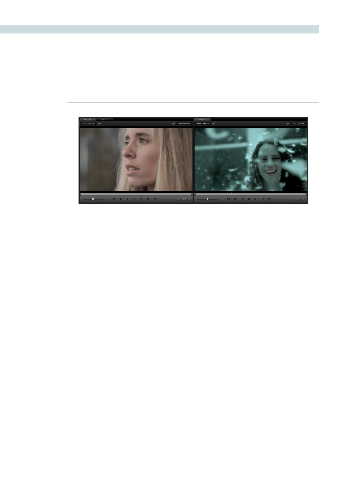
CONFORM 118
The Source and Timeline tabs share the following onscreen controls:
Duration field: In the Source tab, this displays the total duration of the clip, or
the duration from the in to the out point, if these have been
placed. In the Timeline tab, this displays the total duration of the
currently selected session.
Current frame field: In the Source tab, this field shows the timecode of the current
frame at the position of the playhead in the Source tab’s
scrubber bar. In the Timeline tab, this field shows the timecode of
the current frame at the position of the playhead in the Timeline.
Scrubber bar: In the Source tab, drag within the scrubber bar to reposition the
Source playhead, scrubbing through the clip. In the Timeline tab,
drag to reposition the playhead throughout the entire program.
Shuttle slider: Drag the shuttle handle to the right to play forward; the farther
right you drag the faster the playhead moves. Drag the shuttle
handle to the left to play in reverse, playing faster the farther left
you drag.
Transport controls: These controls include, from left to right, Rewind, Step Back,
Play Reverse, Pause, Play Forward, Step Forward, Fast Forward.
Clicking Rewind or Fast Forward multiple times increases the
rate of speed at which the playhead moves.
In/Out buttons: Places In and Out points with which to define a range of the clip,
or of the timeline, in preparation for editing.
The Offline tab has one different control that takes the place of the Duration field:
Offset field: Lets you specify an offset, in frames, with which to sync an
offline-identified media clip that you’ve imported to compare to
the currently selected session. You can select the number in this
field in order to type a new value, or you can use the Up/Down
arrow buttons to alter this value.
The Source and Timeline tabs in the Conform page
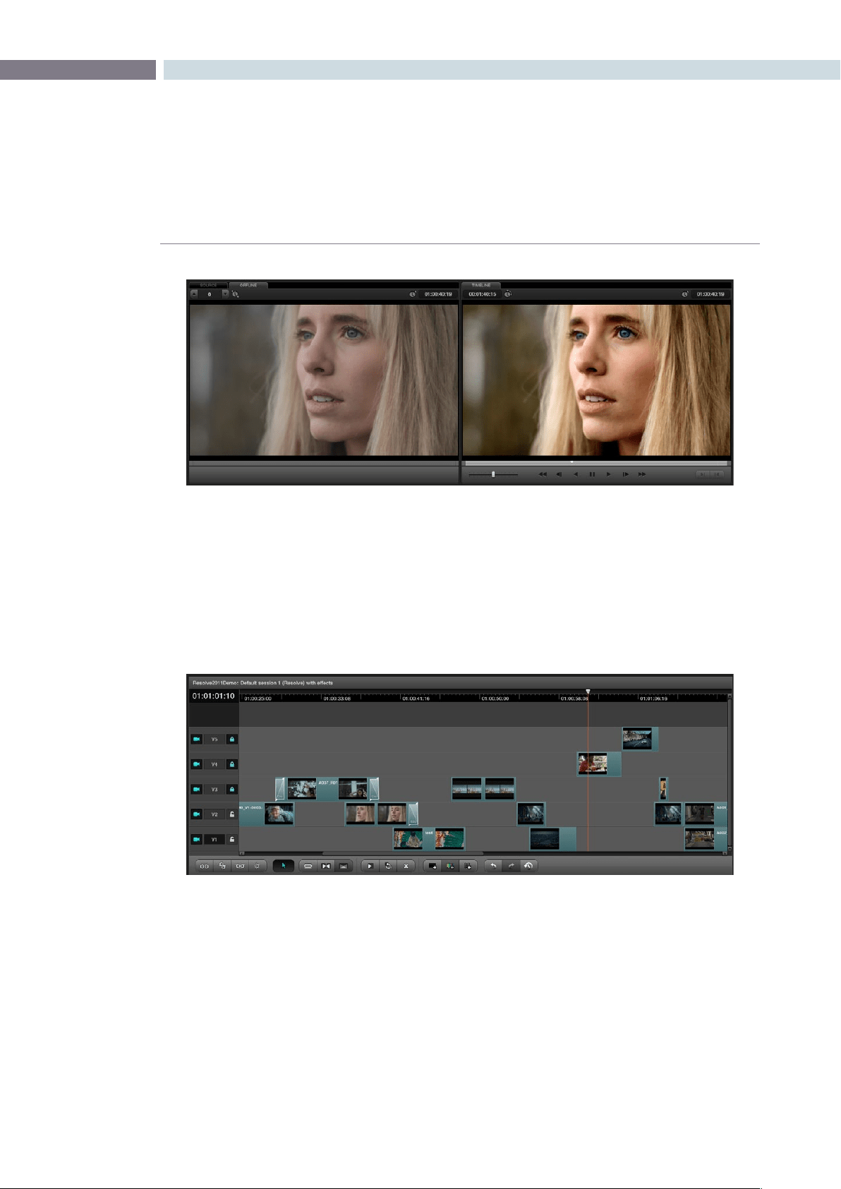
CHAPTER
CONFORM
CONFORM119
8
The Timeline
The multi-track Timeline shows the currently selected session in the Timeline Management list. It
provides a visual representation of the edited program that is helpful for verifying that the project was
imported correctly, checking the media corresponding to each clip in the program, and performing
simple editorial tasks necessary for the grading of some programs, such as replacing or adding clips,
and modifying composite mode or opacity settings.
The Timeline’s contextual menu also contains commands for reconforming clips, adding handles for
rendering, and importing an audio file for synchronized audio during playback. All of these topics will be
covered later in this chapter.
The Offline tab lets you compare an offline export of a sequence at left to the
corresponding graded session clip at right.
The Timeline in the Conform page showing multiple tracks
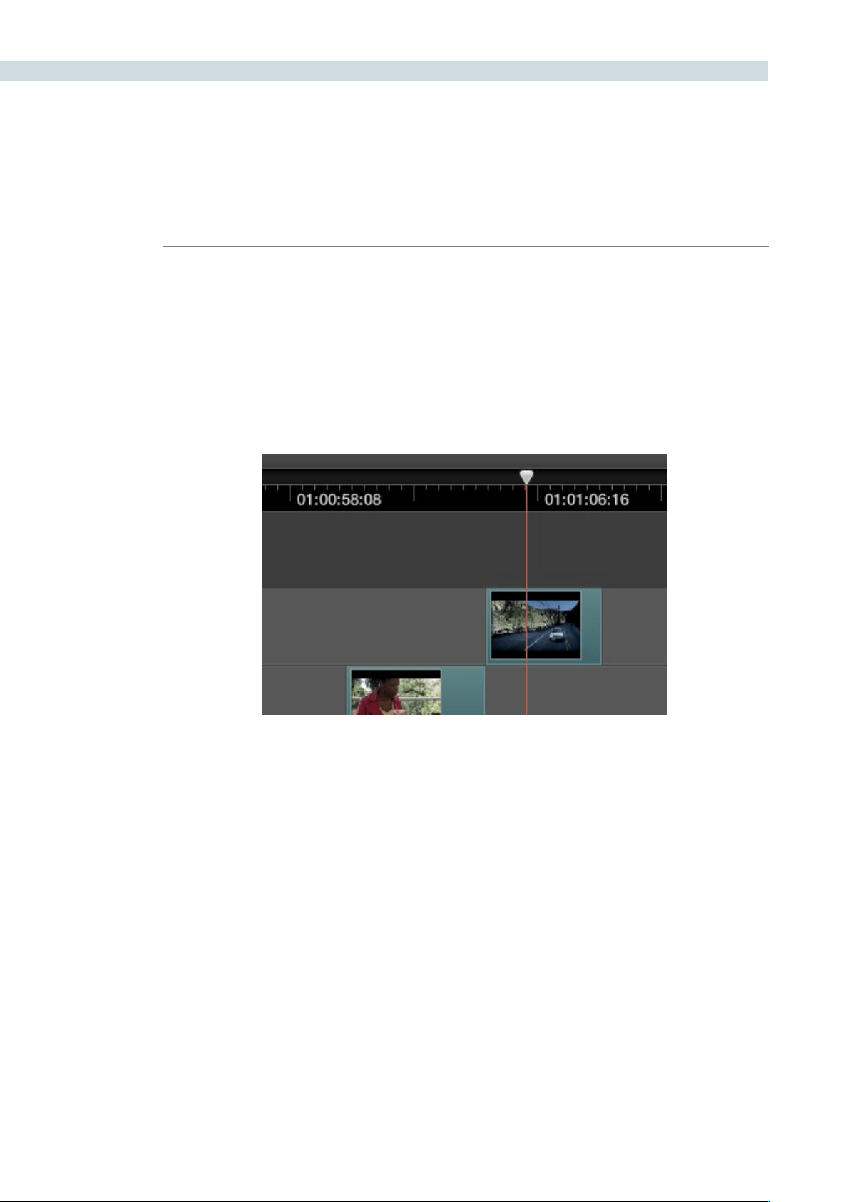
CONFORM 120
The main controls found within the Timeline include:
Current Frame field: Shows the current timecode value corresponding to the position
of the playhead.
Timeline Ruler and Playhead: The Timeline Ruler shows the program’s timecode, and the
playhead indicates the current frame of the current clip.
Whichever clip intersects the playhead is the one that you’ll be
working on in the Color page. Dragging within the Timeline Ruler
moves the playhead.
The Timeline playhead automatically keeps in sync with the Timeline tab’s scrubber bar playhead, the
playheads in the Mini-timeline and Thumbnail timeline of the color page, and the playhead on the Viewer
page. Furthermore, whichever Conform EDL list event corresponds to the clip intersecting the playhead
is automatically highlighted.
Video Tracks: DaVinci Resolve supports multiple video tracks. At the left of
each track is a header area that contains a number of controls.
The playhead, draggable within the Timeline ruler, lets you control playback,
make edits, and select the current clip
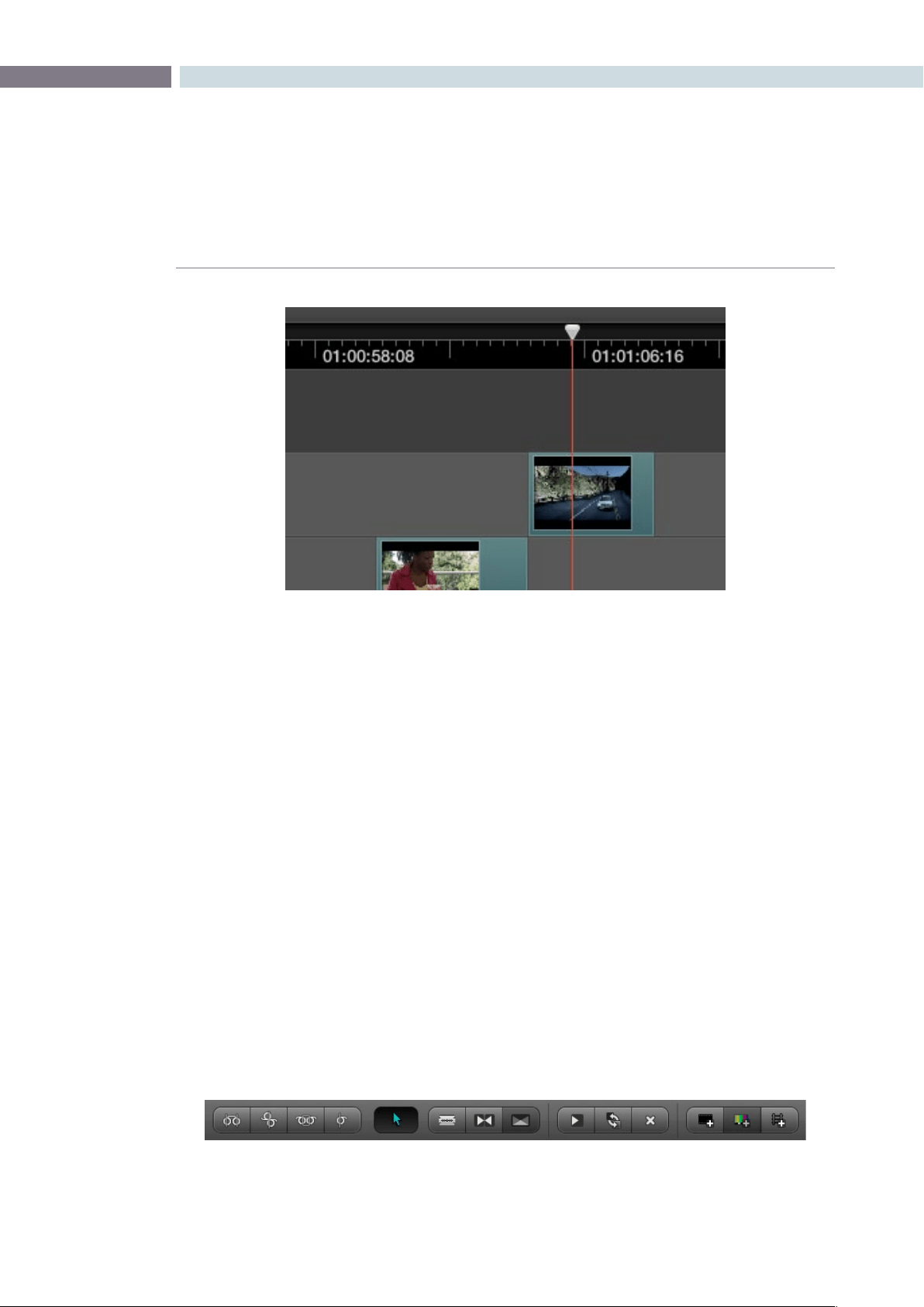
CHAPTER
CONFORM
CONFORM121
8
Enable Track button: The leftmost button lets you turn tracks on and off. The clips for
tracks that are turned off aren’t visible in the Viewer, don’t show
up in the Color page, and aren’t available in the Render window.
Track Number: Each track is numbered according to its position. The bottom
track is V1, and subsequently numbered tracks appear higher
in the Timeline. Click any track’s number to select that track
for different editing functions, the selected track is highlighted
black.
Lock Track button: When turned on, clips can’t be replaced, moved, or otherwise
edited. When turned off, all editorial functions are enabled.
Vertical and horizontal scroll bars:
If your project is longer than the current width of the Timeline, or
the number of video tracks is taller then the current height of the
Timeline, these scroll bars let you navigate around your program.
Use the scroll wheel of your mouse to horizontally zoom into
and out of the Timeline. Scrolling up zooms in, while zooming
down zooms out.
Editing controls: Fourteen buttons starting from the left, running along the
bottom of the timeline, let you perform various editing
functions. These functions are described in greater detail later in
this chapter.
Timeline header area with Enable, Track Number, and lock controls
Editing controls along the bottom of the Timeline
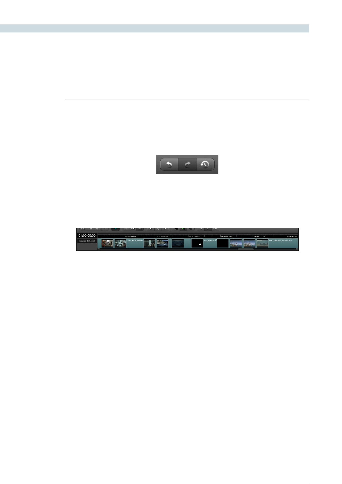
CONFORM 122
Undo/Redo/Edit History: Two buttons let you undo and redo, similarly to using the
Command-ZandCommand-Ykeyboardshortcuts.Athird
button lets you open the Edit History, which shows a list of
each edit you’ve made since creating a particular session, for
purposes of keeping track of your changes.
The Master Timeline
The Master Timeline, at the bottom of the Conform page, always show the contents of the Master
Session, no matter which session is selected in the Timeline Management list.
The Master Session consists of every clip in the Media Pool, excluding offline-designated and matte
clips, arranged in ascending order by timecode.
The Master Session is useful for preliminary grading of media for which no editing has yet been done,
such as digital dailies. For example, you can add all the new media for a project to the Media Pool,
create a Master Session in the Timeline Management list, and then immediately start grading each clip,
exporting the results as a new set of “pre-graded” media with cloned timecode and reel names for the
offline edit.
After editorial, the edited project data can be imported (via EDL, AAF, or XML) as a new session, which
is automatically reconformed to the original media that you graded. Because the grades follow the
timecode of the clips, the new reconformed session already contains your original grades, and you’re
ready to continue working from where you left off.
The Locate in Master Session command lets you see the correspondence between a clip in a session,
and that same clip in the Master Session.
To find a clip in the Master Session:
•Right-clickanyclipintheTimeline,andchoose“LocateinMasterSession”fromthe
contextual menu.
The Master Timeline in the Conform page
Undo, Redo, and Edit History buttons at the bottom right of the Timeline
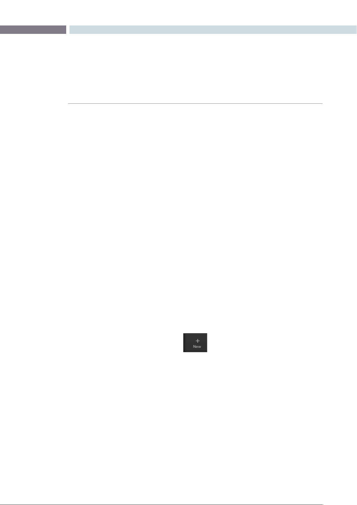
CHAPTER
CONFORM
CONFORM123
8
Creating and Importing Sessions
DaVinci Resolve is extremely flexible, and supports many different workflows such as digital dailies
management, custom project assembly, and project import via EDL, AAF, and XML. When importing
projects, each format has different advantages and disadvantages, and which one is right for any
particular workflow depends mainly on the source application from which the project came.
This section covers the different ways that you can create sessions from scratch, and import project
data to DaVinci Resolve from other applications.
Creating the Master Session
The first session you create within a new project is always the Master Session. Even if you import an AAF
of XML file with its accompanying source media, a Master Session is automatically created, and always
appears at the top of the Timeline Management list.
The Master Session consists of one long sequence of every clip in the Media Pool, arranged in ascending
order by timecode. Each clip in the Master Session appears at its full duration, regardless of the duration
of its corresponding clip in an EDL, AAF, or XML-imported session. Whenever you add more clips to the
Media Pool, they’re automatically added to the Master Session.
The Master Session is useful for organizing media for which no editing has yet been done, such as when
grading digital dailies. The Master Session is also useful for identifying a range of similar clips, based on
their similar ranges of timecode. For example, you could find all the talking head shots from a particular
section of tape clustered together in the Master Session.
To create a Master Session:
1. Open the Browse page, and add one or more media files into the Media Pool.
You cannot create a Master Session unless there’s media in the Media Pool.
2. Open the Conform page, and click the New button, at the bottom of the Timeline
Management list.
3. When the New Session Options window opens, change the Start Timecode if
necessary, and click OK. All new sessions start at hour one by default.
The Master Session appears in the Timeline Management list.

CONFORM 124
Creating a Blank Session
Once the Master Session has been created, you also have the option of creating new, blank sessions.
This can be useful for assembling your own subset of media for grading for example, to sort the Media
Pool by Reel No and add all clips from a particular reel, It can also be useful for manually editing together
your own sequences of clips.
To create a blank session:
1. Open the Conform page, and click the New button, at the bottom of the Timeline
Management list.
2. When the New Session Options window opens, change the Start Timecode if
necessary, enter a name into the Session Name field, turn on the Empty Session
checkbox, and click OK.
A new, empty session is created, ready for you to edit clips into. For more information
on editing in the Conform page, see”Editing in Source/Timeline Mode,” later in
this chapter.
Importing EDL Files
DaVinci Resolve supports the CMX 3600 format for EDL import. The EDL (edit decision list) is the
lowest common denominator project exchange format there is, and most professional postproduction
applications are capable of exporting and importing projects in this format.
Their universality is due, in part, to their longevity; different EDL formats have been in use for decades.
It’s also due to their simplicity. At least as used by DaVinci Resolve, EDLs describe a very narrow range of
editorial information, including clip arrangement, clip name (via embedded comments), video transitions
(dissolves only), and linear speed settings (percentage of fast forward or slow motion) for a sequence
of shots on a single video track.
Note: While the EDL format supports a variety of SMPTE-defined video transition codes, all EDL
transitions are turned into cross dissolves of the same duration in Resolve.
DaVinci Resolve provides several methods of importing projects using EDLs. In all cases, you must first
add the media referenced by that EDL to the Media Pool before you can import its EDL.
The two primary workflows are:
Importing an EDL that references a collection of discrete media files.
Importing an EDL that references a “flattened” master media file. Flattened master
media files are created when an entire program is exported from an NLE as a single
self-contained media file.
CHAPTER
CONFORM
CONFORM125
8
Conforming EDLs to Discrete Media Files
The advantages of working with discrete media files is that they are the “purest” version of the media,
without any effects (such as dissolves or superimpositions) that are “baked” into the visuals that might
create issues when you’re grading.
To create a Master Session:
1. Before you import any media, make sure that the “Timecode calculated at:” pop-up
menu in the Project tab of the Config page is set to a frame rate that matches your
project and media.
2. Open the Browse page, and do one of the following:
Add Folder into Media Pool:
Adds all compatible media files within that folder to the Media Pool. Subfolders are
not traversed.
Add Folder and SubFolders into Media Pool:
Adds all compatible media files from that folder, and all subfolders within that folder, to
the Media Pool.
Add Folder Based on EDLs into Media Pool:
Prompts you to choose an EDL. Only media referenced by that EDL is imported, and
only the selected folder is searched for that media.
Add Folder and SubFolders Based on EDLs into Media Pool
Prompts you to choose an EDL. Only media referenced by that EDL is imported, and the
selected folder and all subfolders are searched for that media.
Tip: The “Add...Based on EDLs” commands are useful for efficiently adding just the media
you need to the Media Pool in instances where there might be terabytes of unmanaged
source media, most of which is unused.
3. Open the Conform page, and click the Load button at the bottom of the Timeline
Management list.
A window appears prompting you to “Choose a file to import.”
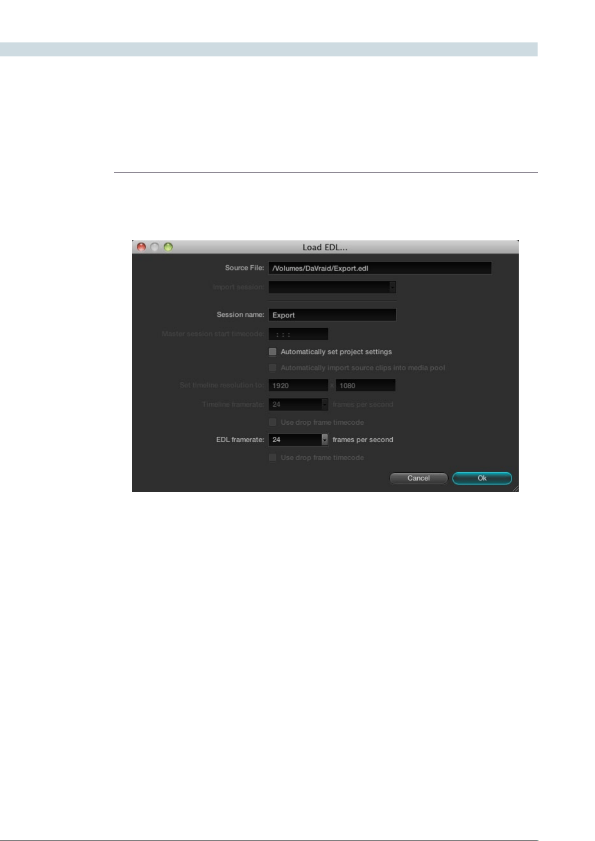
CONFORM 126
4. Navigate to the EDL file you want to use, select it, and click Open.
The Load EDL window appears.
5. Choose the options that are applicable to your particular project:
Source File:
The file you selected in the previous step.
Session name:
The name of the session (or timeline) you’re about to create. This defaults to the name
of the EDL file you selected.
Master session start timecode:
Not editable. The timecode at which the project starts as specified by the first event of
the EDL.
Automatically set project settings checkbox:
Turn this option on if you want to overwrite the frame size setting in the Project tab of
the Config page. You cannot overwrite the Timeline framerate when importing an EDL.
Automatically import source clips into media pool checkbox:
Disabled. You cannot automatically import source clips based on an EDL.
The Timeline in the Conform page showing multiple tracks

CHAPTER
CONFORM
CONFORM127
8
Set timeline resolution to:
Two fields let you specify the width and height of the framesize you want to work at in
Resolve. This defaults to your project settings, but can be overridden by turning on the
“Automatically set project settings” checkbox.
Timeline framerate:
Disabled. This defaults to your project settings.
Use drop frame timecode checkbox:
By default, this is derived from the frame rate of the selected file.
EDL framerate:
Choose the framerate of the sequence that you exported as an EDL. You can convert
the EDL framerate from 30 to 24 frames per second if you set the Timeline framerate
to 24 fps and if the EDL framerate is set to 30 fps; this is useful when an offline edit is
done at 30 fps with media using 3:2 pulldown. Note that 25 fps to 24 fps conversion is
not supported.
Use drop frame timecode checkbox:
Only enabled if the EDL framerate pop-up menuis set to 30 fps, turn this on if your EDL
uses drop-frame timecode.
6. When you’re finished choosing options, click OK.
The EDL is imported, a new session appears highlighted in the Timeline Management
list, and its corresponding sequence of clips appears in the Timeline. Clips that could not
be linked to a corresponding file in the Media Pool appear with a red x to indicate that
they’re unconformed.
Conforming EDLs to “Flattened” Master Media Files
On the other hand, preparing an edited sequence for grading, along with each individual clip of media,
can be time-consuming for effects-intensive projects, or it may be an unnecessary step for a project
with no effects whatsoever.
In these cases, it can be simpler and quicker to export a flattened master media file that can be split
back apart into its individual clips in DaVinci Resolve. This workflow is similar to the traditional tape-to-
tape workflow, except that you’re using a digital, rather then a tape-based master to work from.
There are two ways you can do this. The easiest is to use the Preconform button in the Conform page
to split a single master file back into the individual clips it’s made up within a new session.
To preconform a flattened master media file to an EDL:
1. Before you import any media, make sure that the “Timecode calculated at:” pop-
up menu in the Project tab of the Config page is set to a frame rate that matches
your project.
Make sure you’ve picked the correct frame rate, since this option can’t be changed
once you’ve added media to the Media Pool.
CONFORM 128
2. If necessary, turn on the “Assist using reel numbers from the:” checkbox in the Project tab
of the Config page, and click to choose the appropriate option underneath. For example,
if you’re relinking to R3D media, the default setting of the “Source clip file pathname” will
base the reel names of each clip on the source media’s file name.
If you discover later that you’ve chosen the wrong option, you can change this
setting later.
3. Open the Browse page, use the Media Storage and Clip Details lists to navigate to the
flattened master media file that contains the entire program, and double-click the file to
add it to the Media Pool.
4. Open the Conform page, and click the Preconform button.
5. In the “Select an EDL file” dialog that appears, navigate to the EDL that matches the
flattened master media file, select it, and click Open.
6. In the “Parse preconform options” dialog that appears, give the new session a name,
and click OK.
A new session appears in the Timeline Management list, the Conform EDL list is populated
with the events of the imported EDL, and the Timeline shows the session’s edited clips,
ready for grading. Clips that could not be linked to a corresponding file in the Media Pool
appear with a red x to indicate that they’re unconformed.
The second method of conforming an EDL to a flattened file is to use the “Split and Add” command in
the Browse page to split one or more master media files into individual clips that match those of an EDL,
importing the EDL itself in the Conform page in a second step.
This method is useful if there are clips in different folders or volumes that you want to conform to a
single EDL. For example, the majority of the first reel of a program may have been exported as a single
flattened file, but the corresponding EDL may require an additional folder of effects clips be added to
the Media Pool in order to be fully conformed.
Splitting a flattened media file in the Browse page, and importing its EDL in the Conform page:
1. Before you import any media, make sure that the “Timecode calculated at:” pop-
up menu in the Project tab of the Config page is set to a frame rate that matches
your project.
2. Open the Browse page, use the Media Storage and Clip Details lists to navigate to the
flattened master media file that contains the entire program.
3. Select the flattened media file, right-click it, and choose “Split and Add into Media Pool.”
4. In the “Select EDL files for splitting clips” dialog that appears, navigate to the EDL that
matches the flattened master media file, select it, and click Open.

CHAPTER
CONFORM
CONFORM129
8
5. Select the frame rate of the project from the File Conform Frame Rate dialog that
appears. This frame rate should be identical to the “Timecode calculated at:” pop-up
you set in step 1.
6. Choose the appropriate options in the “Enter handle size for splitting” dialog
that appears:
Handle size in number of frames:
Enter a number of frames to be added as handles to the first and last frame of the clip.
This is useful when you’re using the “Split and Add into Media Pool” command to import
only the referenced sections of a directory of individual media files.
Split Unreferred Clips:
Useful when the referenced media files include segments that aren’t “referred to” by
the EDL used to split them up. Turning this checkbox on adds all such unreferred clip
segments to the Media Pool as separate clips, for possible later use.
7. Click Split & Add.
The Media Pool fills up with individual segments of the flattened master media file,
each of which matches an event in the EDL you used to split it.
8. Open the Conform page, and click the Load button at the bottom of the Timeline
Management list.
9. In the “Choose a file to import” dialog that appears, navigate to the EDL that matches
the flattened master media file, select it, and click Open.
10. Choose whatever options are necessary from the Load EDL dialog that appears, and
click OK. The default settings should work fine.
The Master Session and the session you just imported appear in the Timeline
Management list, the Conform EDL list updates with the events from the imported
EDL, and the Timeline shows the session’s edited clips, ready for grading.
Clips that could not be linked to a corresponding file in the Media Pool appear with a
red x to indicate that they’re unconformed.
About AAF Import
AAF (advanced authoring format) is another project exchange format, originally developed by the
Advanced Media Workflow Association (AMWA), that contains more metadata then the simpler EDL
format. Commonly used applications that export project data in the AAF format include Avid Media
Composer and Adobe Premiere Pro.
When you import AAF files, you don’t have to import media into the Media Pool first. You have the
option to automatically import all source clips that are referenced by the AAF file into the Media Pool.
However, automatically imported source clips must be in a format that is compatible with DaVinci
Resolve. Both Media Composer and Premiere Pro are compatible with more media formats than
Resolve, and if you try to automatically import unsupported media, project import will be cancelled.

CONFORM 130
Because of its similarity to importing XML files, the procedure for importing AAF files can be found
later in this chapter, in “Importing AAF and XML Files .” A list of compatible media formats appears
in an appendix to this manual. For the most up to date list of compatible media formats, see
www.blackmagic-design.com.
About XML Import
DaVinci Resolve can also import projects that were exported to the Final Cut Pro XML format. Since this
format was designed to contain every type of editorial construct and effect that Final Cut Pro is capable
of using within a project, this project format has the most metadata of all.
DaVinci Resolve is capable of translating a subset of the effects in a Final Cut Pro XML project file into
their Resolve equivalents, but not all.
Supported Effects
The following subset of effects are compatible with DaVinci Resolve:
Composite Modes
Transitions
Opacity settings
(along with keyframes, they’re nonadjustable within Resolve)
Linear Speed effects
For more information about supported effects in Resolve, see the “Working With Effects” section later
in this chapter.
Unsupported Effects
Resolve is not currently compatible with:
Still images with greater then 1 frame duration
Freeze Frames
Final Cut Pro Filters
Variable Speed effects
Motion settings, either animated or non-animated
Generators, Motion clips, and Master Templates
Nested sequences
(XML files with nested sequences won’t import at all)
Audio (all audio is stripped from the project)
Even though these unsupported effects are neither imported nor displayed in Resolve, the majority
of them are preserved internally, and are reinserted into exported XML files so that those effects will
reappear in Final Cut Pro.
Important: When preparing edited sequences for DaVinci Resolve import, do not use media with mixed
frame rates. Resolve treats all media as if it were at the frame rate of the project, so importing a mixed
frame rate sequence may produce unexpected results.

CHAPTER
CONFORM
CONFORM131
8
Effects Processing When Finishing in DaVinci Resolve
When you’re outputting to tape, rendering a QuickTime master of your project, or rendering a DPX
image sequence for film output, all supported effects are rendered by Resolve and “baked” into the
output media.
Unsupported effects are completely ignored, cannot be seen, and have no effect on media that’s
rendered and output. If there is an unsupported effect applied to a clip in your NLE of choice that you
want to move into DaVinci Resolve, for example a pan and scan effect that’s applied to a still image file,
here’s a simple workflow to follow.
To “bake” an effect into a clip you’re sending to DaVinci Resolve:
1. Export that clip as a self-contained media file using whatever Resolve-compatible
mastering codec you prefer.
2. Reimport the resulting media file into your project.
3. Edit it into the sequence to replace the original effects clip.
4. Export an XML version of the resulting sequence for use in Resolve.
This is a good way of prepping the titles and effects of projects that you want to finish in DaVinci
Resolve. If you create self-contained QuickTime movies of all title clips and effects, then these elements
will import cleanly and easily, and you can export a complete, texted version of your program out
of Resolve.
Here’s another tip. If a superimposed clip is using unsupported effects, for example, a filtered still image
with pan and scan effects that’s superimposed using the Overlay composite mode and set to 70%
opacity, an ideal way to prep this clip for XML export to Resolve is to set the composite mode to
Normal, set Opacity to 100%, and then export the resulting clip as a self-contained QuickTime movie.
Reimport the result, edit it back into the timeline to replace the original superimposed clip, and then
set its composite mode to Overlay and its Opacity to 70% to match the original settings. Now the
unsupported effects are “baked” into the clip, but the effects that Resolve does support are still live, and
can be readjusted in context while grading.
Effects Processing in Round-Trip Workflows
In workflows where you want to send a project back to an NLE after grading for final finishing, adding
titles and other effects before to final delivery, Resolve handles different effects in different ways.
Unsupported effects do not appear in Resolve. However, the effects data is preserved, invisibly, and
when you export an XML file to send back to Final Cut Pro, the effects all reappear, this time applied to
the color corrected media that you rendered out of DaVinci Resolve.
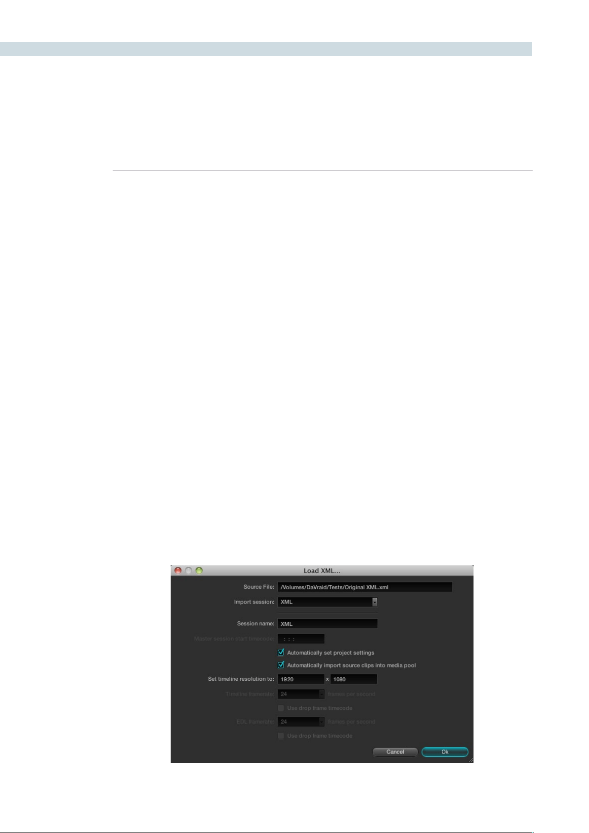
CONFORM 132
Speed effects, composite modes, opacity settings, and transitions are handled differently. Even though
these effects are visible in Resolve while you work, they’re not “baked” into the final media that you
render in preparation for sending back to Final Cut Pro. Instead, the portion of each media clip that’s
used in your project is rendered as an individual file, and the XML file that you export from Resolve
contains all the effects information necessary to reassemble the rendered media into a timeline that
uses Final Cut Pro effects applied to Resolve-graded media.
At that point, you’re free to readjust these effects in the course of the finishing of your program,
without the need to re-render individual clips in Resolve.
Important: There are two exceptions to the preservation of media and effects in round trip workflows.
Audio is permanently stripped from the XML of any projects that are imported into Resolve, and does
not reappear in Final Cut Pro. Also, nested sequences are not compatible with Resolve; XML files
containing nested sequences cannot be imported at all.
Importing AAF and XML Files
The procedure for importing projects via an AAF or XML file is very similar to that for importing an EDL.
However, because AAF and XML files contain metadata describing the location of referenced media,
you have the option of importing a project and the source clips it references at the same time, without
the need to add clips to the Media Pool first.
To load an AAF or XML file and automatically link to its referenced media:
1. Open the Conform page, and click the Load button at the bottom of the Timeline
Management list.
A window appears prompting you to “Choose a file to import.”
2. Navigate to the AAF/XML file you want to use, select it, and click Open.
The Load AAF or Load XML window appears, depending on your selection.

CHAPTER
CONFORM
CONFORM133
8
3. Choose the options that are applicable to your particular project. By default, these
options are based on metadata within the file you selected.
Source File:
The file you selected in the previous step.
Session name:
The name of the session, or timeline, you’re about to create. This defaults to the name of
the sequence that was exported.
Master session start timecode:
The timecode at which the project starts.
Automatically set project settings checkbox:
Turn this option on if you want to overwrite the frame size and frame rate settings in the
Project tab of the Config page with those in this window.
Automatically import source clips into media pool checkbox:
Turn this option on to automatically import the media referenced by the AAF or XML
project file you selected into the Media Pool for immediate reconnection.
Set timeline resolution to:
Two fields let you specify the width and height of the framesize you want to work at in
Resolve.
Timeline framerate:
By default, this is derived from the frame rate of the selected file.
Use drop frame timecode checkbox:
By default, this is derived from the frame rate of the selected file.
EDL framerate:
By default, this is derived from the frame rate of the selected file.
Use drop frame timecode checkbox:
By default, this is derived from the frame rate of the selected file.
4. After choosing all necessary settings, click OK.
5. As a result of enabling “Automatically import source clips into media pool,” another
window appears prompting you to choose the folder within which the media for this
project is stored. Navigate to the folder containing your media, select it, and click Ok. All
subfolders will be automatically traversed as well.
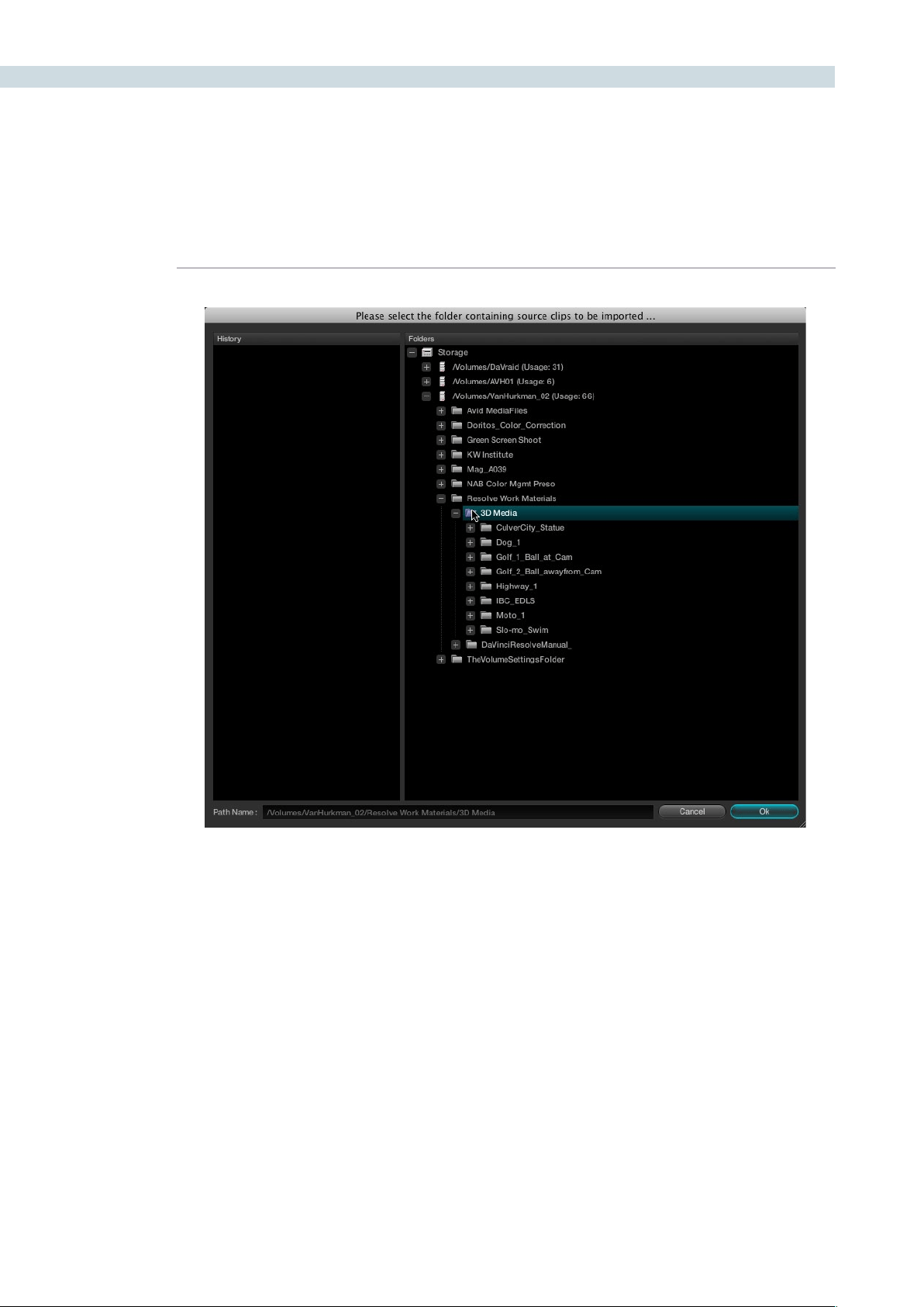
CONFORM 134
For example, if you’re importing an AAF from Avid Media Composer, you’ll likely want to
select the “Avid Media Files” folder, on whichever volume you’ve put it. Be aware that even
though Resolve traverses all the subfolders of whichever folder you select, if you select
a folder with many subfolders such as your entire hard drive, it may take considerably
longer to find the media.
Important: If you didn’t add the volume containing the AAF media to the Media Storage
Volumes list of the DaVinci Resolve Preferences, it won’t be available to select.
The AAF/XML file is imported. A new session appears in the Timeline Management list,
the referenced media files appear in the Media Pool, and the edit appears in the Timeline.
Clips that could not be linked to a corresponding file in the Media Pool appear with a red
x to indicate that they’re unconformed.
If the media referenced by the AAF or XML file is not in a compatible format, or if you want to reconform
the AAF or XML project to a higher-quality set of media files, then you can follow a different procedure.

CHAPTER
CONFORM
CONFORM135
8
Import a different set of Resolve-compatible media into the Media Pool of the Browse page that has
identical timecode and reel names to that referenced by the project. Then, import the AAF or XML file
without automatically importing source clips in order. When you do this, the new session is reconformed
to the Media Pool clips.
To load an AAF or XML file and manually reconform it to clips in the Media Pool:
1. Before you import any media, make sure that the “Timecode calculated at:” pop-up menu
in the Project tab of the Config page is set to a frame rate that matches your project.
2. If necessary, turn on the “Assist using reel numbers from the:” checkbox in the Project tab
of the Cofig page, and click to choose the appropriate option underneath. For example,
if you’re relinking to R3D media, the default setting of the “Source clip file pathname” will
base the reel names of each clip on the source media’s file name.
If you discover later that you’ve chosen the wrong option, you can change this
setting later.
3. Open the Browse page, and do one of the following:
Add Folder into Media Pool:
Adds all compatible media files within that folder to the Media Pool. Subfolders are
not traversed.
Add Folder and SubFolders into Media Pool:
Adds all compatible media files from that folder, and all subfolders within that folder, to
the Media Pool.
Note: You cannot use the Add Folder...Based on EDLs into Media Pool” commands with
either XML or AAF files.
4. Open the Conform page, and click the Load button at the bottom of the Timeline
Management list.
A window appears prompting you to “Choose a file to import.”
5. Navigate to the AAF/XML file you want to use, select it, and click Open.
The Load AAF or Load XML window appears, depending on your selection.
6. Turn off the “Automatically import source clips into media pool” checkbox.
7. Choose any other options that are applicable to your particular project, and click OK.
For more information on these options, see the previous procedure in this section.
The AAF/XML file is imported and relinked to the corresponding media in the Media
Pool using reel name and timecode. A new session appears in the Timeline Management
list, and the edit appears in the Timeline.
Clips that could not be linked to a corresponding file in the Media Pool appear with a
red x to indicate that they’re unconformed.
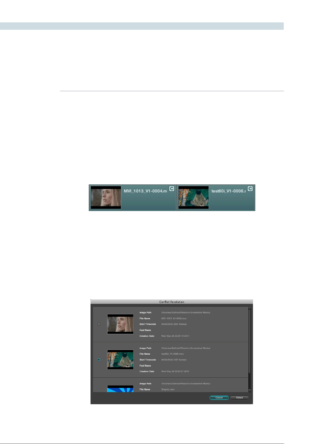
CONFORM 136
Dealing With Reel Conflicts
While importing projects from other applications, clips with overlapping timecode and reel names will
cause reel conflicts. This often occurs when media has been added with timecode but no reel identifier,
for example shots from multiple unidentified reels that all start at 0 hour. This may also occur if shots are
added to the Media Pool incorrectly, such as when replacement shots are added to the Media Pool but
the original media is still there.
Tip: Overlapping timecode often occurs in the normal course of work, but should be managed by
altering each clip’s embedded reel name, or by organizing media in different folders.
Reel conflicts within a session can be identified in the timeline by a “C” icon in the thumbnail.
Fortunately, DaVinci Resolve has an easy way of resolving reel conflicts.
To resolve a reel conflict by relinking a clip’s media:
1. Right-click the “C” icon of any clip in a session’s timeline, in the middle of the
Conform page.
The Conflict window appears, showing a list of all the files in the Media Pool with timecode
that overlaps the clip you right-clicked. Each item in the list has a thumbnail of the clip,
the path of the file, file name, starting timecode, reel name, and creation date, to help you
determine which of the clips in that list is the correct one.
Timeline with two clips indicating timecode conflicts
The Conflict Resolution dialog
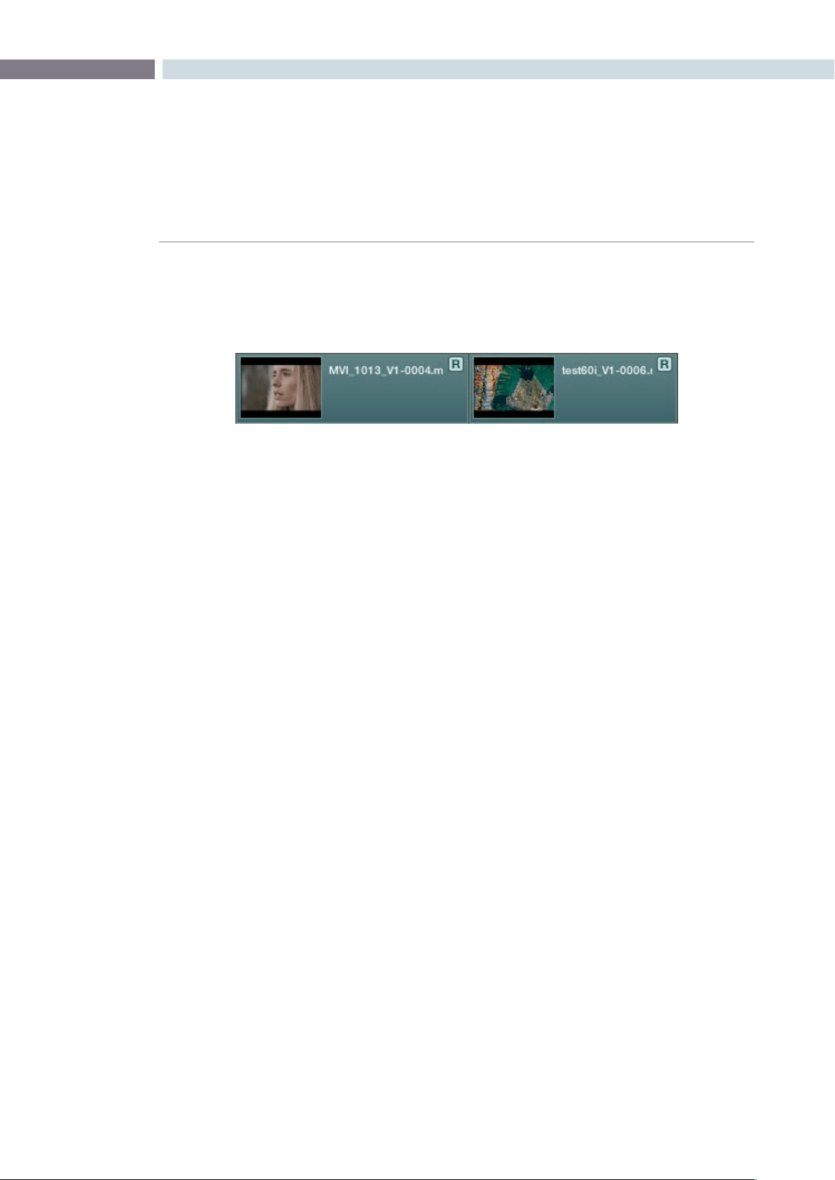
CHAPTER
CONFORM
CONFORM137
8
2. Click the radio button of the correct media file for that clip, and click Apply.
The clip in the Timeline changes to reflect the media you selected, and the “C” icon is
replaced with an “R,” indicating the conflict has been resolved.
To resolve a reel conflict by copying a grade:
1. Right-click the “C” icon of any clip in the Master Session, at the bottom of the
Conform page.
The Conflict window appears, showing a list of all the clips with overlapping timecode.
Each item in the list has a thumbnail of the clip, the path of the file, file name, starting
timecode, reel name, and creation date, to help you determine which of the clips in that
list is the correct one.
2. Choose the correct media file for that clip by clicking its radio button, and click Apply.
What happens after you click Apply depends on whether you right-clicked the session
Timeline in the middle of the Conform page, or the “C” icon in the Master Session at the
bottom of the Conform page.
•Right-clickingthe“C”iconinaselectedsession’sTimelinechangeswhatmediathat
clip is linked to.
•Right-clickingthe“C”iconintheMasterSessioncopiesthatclip’scorrectionfromthe
Master Session clip to the conflicting clip in the other timeline.
What happens after you click Apply depends on whether you Right-clicked the session
Timeline in the middle of the Conform page, or the “C” icon in the Master Session at the
bottom of the Conform page.
The “C” icon is replaced with an “R,” indicating that the conflict has been resolved.
Timeline with two clips indicating timecode conflicts

CONFORM 138
Linked and Unlinked Grades in Multiple Sessions
By default, any clips that refer to the same file in the Media Pool are linked and share the same
remote versions of grades that are applied to them. For example, two clips that are close-ups
from the same take refer to the same media file, so they’re both automatically linked to one
another and share the same remote grades.
This is also true for clips that appear in multiple sessions. Clips that are located in different
sessions, but that refer to the same file in the media pool, are linked and share the same
remote versions of grades. This is why you can grade one session, and then import a reedited
version via EDL, AAF, or XML, and have the new session automatically inherit all of the grades
from the previous session.
However, you can override this behavior to have one session that’s independently graded
from the others. Simply select that session, open the Color page, right-click any clip in the
Thumbnail timeline, and choose Batch Copy from the contextual menu. All grades are copied
to Local Versions, and from that point on all changes you make to grades in that session have
no effect on the other sessions in your project.
For more information about Local and Remote sections, see the Color chapter.
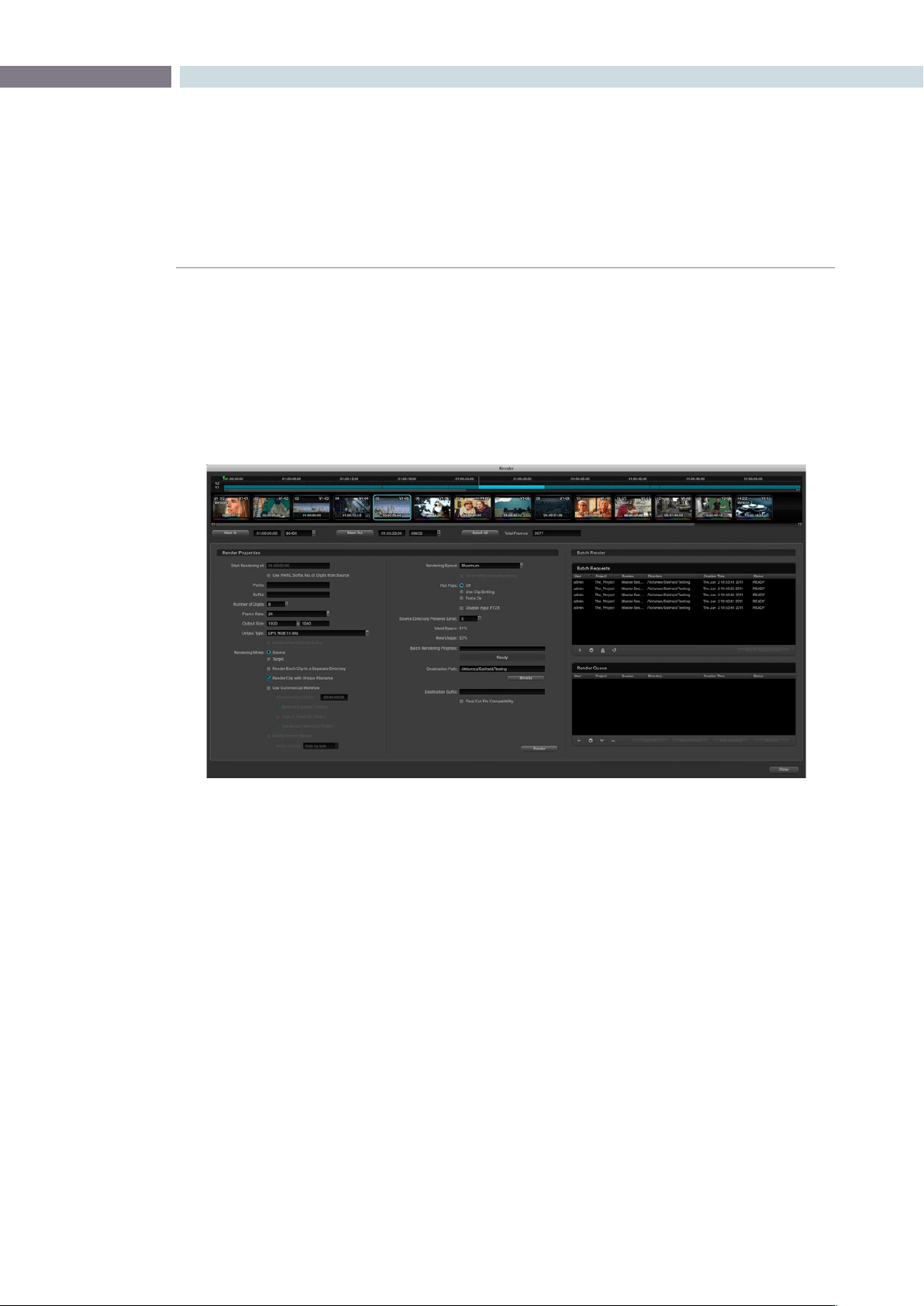
CHAPTER
CONFORM
CONFORM139
8
Once you’ve graded a program, you may find it necessary to send it to another application for finishing.
DaVinci Resolve lets you export individual sessions as EDLs or XML files, for sending to an NLE or
finishing application along with its accompanying rendered media.
Rendering Media to Accompany Exported Projects
To send a graded project to another application, you need to render it first using the Render window,
available from the Session menu when you’re in the Color page.
There are numerous options in the Render window for selecting which clips are rendered, and controlling
how they’re named, whether they’re exported as individual clips (Source mode) or as one long flattened
file (Target mode), where they’re written to, etcetera.
For purposes of sending a session and its rendered media to another application, you need to render
a session in Source mode. In this mode, Reel Name and Timecode metadata for each rendered clip are
cloned from the original media, making it possible maintain the correspondence between project and
media. Furthermore, if you’re exporting XML to send back to Final Cut Pro, a “Final Cut Pro Compatibility”
checkbox automatically chooses all the optimal settings for rendering media that will smoothly relink to
the accompanying XML file.
For detailed information about using the Render window, the Render chapter.
Creating a Session With Handles
If you need to render media with handles before exporting a session to another application, you first
need to create a duplicate version of the graded session, or the Master Session, in the Conform page.
Handles are useful if you’re recording a session to tape and need pre-roll time. They’re also good for
handing a graded project and its media back to an editor for continued re-editing in their NLE of choice.
Exporting Sessions
The Render window lets you render some or all of the clips in your graded project for export.
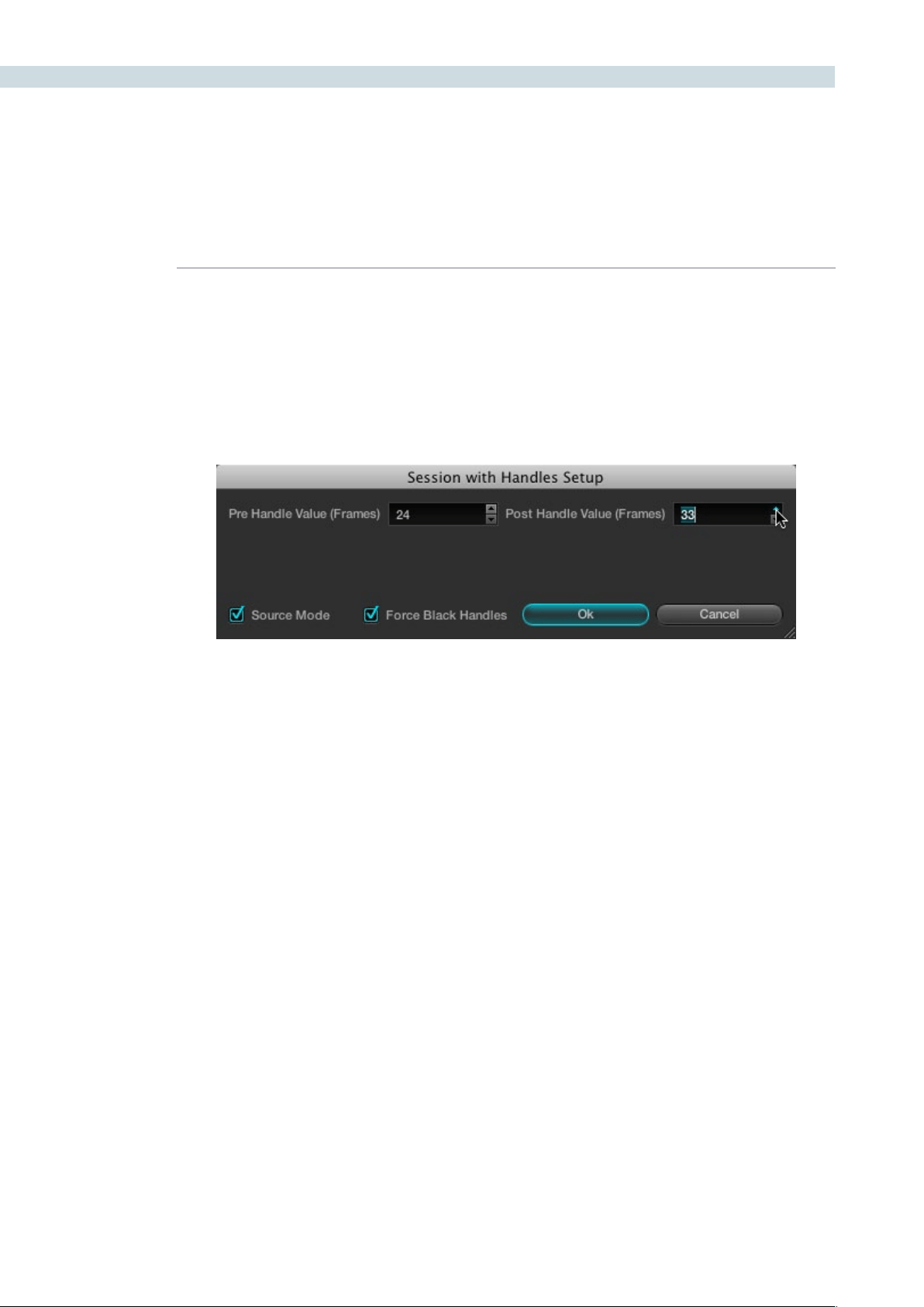
CONFORM 140
To create a session with handles:
1. Open the Conform page and select the session you want to add handles to in the
Timeline Management list.
2. Right-click anywhere in the Timeline and choose “Create Session with Handles” from
the contextual menu.
The Session with Handles Setup dialog appears.
3. Adjust the following settings:
•PreHandleValue(Frames)eld:Thenumberofframestoaddbeforetheinpoint
of the clip. Type a number in the field, or use the up/down arrows to adjust the value
a frame at a time.
•PostHandleValue(Frames)eld:Thenumberofframestoaddaftertheoutpoint
of the clip. Type a number in the field, or use the up/down arrows to adjust the value
a frame at a time.
•SourceModecheckbox:Sortstheclipsinthenewsessioninascendingorder,
according to source timecode.
•ForceBlackHandlescheckbox:Forclipsthatlackextramediaattheheadortail,
turning on this checkbox renders black instead, creating handles where previously
there were none.
4. When you’re finished, click OK, and when a Conform Settings dialog appears, verify the
settings you selected and click OK a second time.
5. If you want, type a custom name for the new session in the Session Name dialog that
appears, and click OK. By default, the new name is that of the previous session with
“(Handles)” appended to it.
A new session is created, with clips that are longer to reflect the handles that
were added.

CHAPTER
CONFORM
CONFORM141
8
Keep in mind that sessions with handles have completely different timing then the original session, and
are not meant to be used, played, or exported in place of the originally graded session. Sessions with
handles are only meant to be used to render media with handles. To export an EDL or XML file, select
the originally graded session first.
Exporting EDLs
If you’ve re-edited a session, or you’ve rendered media with reel names or timecode that doesn’t match
the original media you imported, you can export a new EDL that reflects these changes, and that can
be reimported into whatever application you want to send the graded project to.
Tip: If you haven’t re-edited the session, and you haven’t changed the reel names or timecode of the
rendered clips, you may be able to simply relink the original edited sequence in whichever NLE it
originated to the graded media rendered by DaVinci Resolve. Keep in mind that in Source mode, the
Render window automatically clones the reel names and timecode of each rendered clip so that the
graded clips match the original ungraded clips.
To export an EDL:
1. Open the Conform page and select the session you want to export an EDL from in the
Timeline Management list.
2. Right-click anywhere in the Timeline and choose “Save EDL” from the contextual menu.
3. When the Save EDL dialog appears, type a name and choose a location for the
exported EDL, then click Save.
The EDL is saved, and a dialog appears reminding you of the file path to which it was
saved. Click OK to dismiss it.
Exporting XML Files Back to Final Cut Pro
If you’re doing a Final Cut Pro to Resolve round trip, the Conform page is where you export the XML file
you want to send back to Final Cut Pro after you’ve rendered the graded media.
Keep in mind that you can freely re-edit projects that you’re planning to send back to Final Cut Pro,
splitting clips, adding transitions, adding and replacing media, and altering edit points. The state of a
session’s timeline when you export an XML file is what appears when you import that XML file back into
Final Cut Pro.
You can also send projects back to Final Cut Pro via XML if they were originally imported via EDL or
AAF, making this a very robust way of moving projects from Resolve to Final Cut Pro regardless of
where they originated from.
To export an XML file after you’ve rendered the graded clips:
1. Open the Conform page and select the session you want to export an XML file from in
the Timeline Management list.
2. Click the Export button at the bottom of the Timeline Management list.

CONFORM 142
3. When the Export XML dialog appears, type a name for the file and choose a location
for the exported XML file, then click Save.
An XML version of that session is saved, complete with internal references to the
graded media you rendered, and ready for importing into Final Cut Pro.
Exporting CDL Files
DaVinci Resolve can export and import basic grading data to and from other applications via a Color
Decision List (CDL). CDLs are an industry-standard file format originally developed by the American
Society of Cinematographers’ technology committee, and Resolve supports the 1.2 CDL standard that
defines the slope, offset, and power for each of the red, green, and blue channels, as well as the overall
saturation (SOPS) of each clip in a program.
CDL files are formatted similarly to EDLs, with the addition of embedded SOPS values. Here’s an
example a single CDL event:
020 001 V C 03:02:49:13 03:02:53:00 01:01:28:11 01:01:31:22
*ASC_SOP (1.109563 1.717648 0.866061)(-0.238880 -0.390357 0.353743)(0.672948
1.384022 0.889876)
*ASC_SAT 1.000000
Because the CDL definition of a grade is so narrow, projects that you’re planning to export to other
applications via a CDL must be constrained to only those operations the CDL defines. Here are some
things to keep in mind:
Restrict yourself to using the Lift/Gamma/Gain, Offset, and Saturation controls.
Only the primary grades on the first node of every clip are exported.
Marks (keyframes) are not exported. If marks are present in a grade, only the parameter
values at first frame of the clip are used.
Nodes added to the Track tab are ignored.
If there is HSL Qualification or a Power Window in the first node, it is ignored and the
grade is exported as if it were a primary correction.
Do not make Y’-only adjustments, they’re not compatible with CDLs. To ensure that
yourexportedCDLisaccurate,setthe‘MakeLUM’parameterforeachgradeto0.
For workflows involving frequent CDL export, you can turn on the “Luminance Mixer
defaults to zero” option in the Settings tab of the Config page to make sure it’s always
set to 0.
If your session conforms to all of these restrictions, then you’re ready to export a CDL.

CHAPTER
CONFORM
CONFORM143
8
To export a CDL:
1. Open the Conform page and select the session you want to export an EDL from in the
Timeline Management list.
2. Right-click anywhere in the Timeline and choose “Save CDL” from the contextual menu.
3. If a warning dialog appears warning that the Lum Mix parameter is not set to 0, it’s
recommended that you cancel the operation and fix the issue. Otherwise, if you’re
certain that your grades are set up properly, click Save to continue.
4. Enter a name for the CDL, choose a location to save it to, and click OK.
For more information on importing a CDL to add grades to your project, see “Using Color Trace to Apply
Grades From One Project to Another,” later in this chapter.
Exporting ALE Files
DaVinci Resolve is also capable of exporting ALE (Avid Log Exchange) files. ALE is an ASCII text-based
clip logging list format that enables the exchange of clip metadata that can’t be included with MXF files.
To export an ALE file:
1. Open the Conform page and select the session you want to export an ALE file from in
the Timeline Management list.
2. Right-click anywhere in the Timeline and choose “Export ALE” from the contextual
menu.
3. Enter a name for the ALE file, choose a location to save it to, and click OK.
The ALE file is saved, and a dialog appears reminding you of the file path to which it
was saved. Click OK to dismiss it.
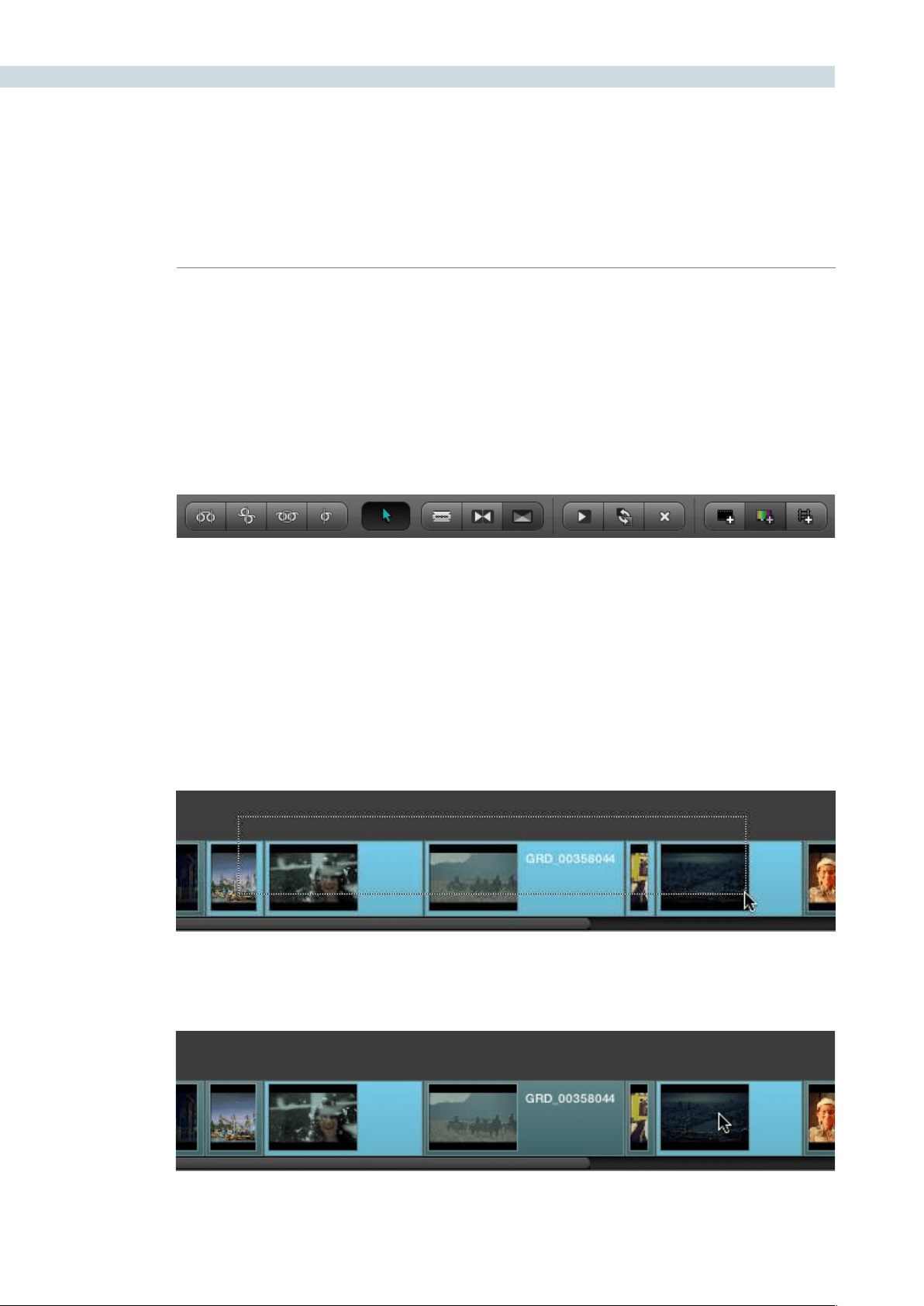
CONFORM 144
DaVinci Resolve has a suite of simple editing tools that make it convenient to perform common online
editorial and timeline management operations. There are also effects functions available for making
alterations to clip speed, opacity, and composite modes for superimposed clips.
Simple Editing
This section outlines the different editing techniques that you can use in the Conform page of DaVinci
Resolve. Most editing functions can be accessed either using the tool buttons at the bottom of the
Timeline, or from the Timeline contextual menu available by right-clicking various objects in the Timeline.
Note: Not every editing button is currently functional. At the time of this writing, the Transitions and
Color Bars buttons are inactive pending future development.
The following procedures outline editing methods available in the Conform page of DaVinci Resolve.
Methods of selecting clips in the Media Pool or Timeline:
To select a contiguous range of clips:
Drag a selection box over all the clips you want to select.
To select a noncontiguous range of clips:
Command-click each clip you want to include in the selection.
Editing in Source/Timeline Mode
Editingtoolsfromlefttoright:Slip,Roll,Slide,Ripple,NormalEditMode,SplitClips,JoinClips,Transition(disabled),
Insert Clip, Replace Clip, Delete Clips, Insert Black, Insert Color Bar (disabled), Add Track

CHAPTER
CONFORM
CONFORM145
8
To add clips to the Timeline by drag and drop:
Drag a clip from the Media Pool to a location in the Timeline.
To insert-edit one or more clips into the timeline:
1. Move the playhead to the frame of the Timeline where you want to insert a clip.
2. If necessary, create a new track if you want to superimpose the new clip.
3. Click the track number control of the track you want to insert the clip onto.
4. Select one or more clips in the Media Pool, right-click one of the selected clips, and
choose “Insert Selected Clips to Session”
The selected clips in the Media Pool are insert edited to the selected track at the position
of the playhead, pushing all other media in that track back by the total duration of the
selected clips.
To append one or more clips to the end of a track:
1. Move the playhead to the frame of the Timeline where you want to insert a clip.
2. If necessary, create a new track if you want to superimpose the new clip.
3. Click the track number control of the track you want to insert the clip onto.
4. Select one or more clips in the Media Pool, right-click one of the selected clips, and
choose “Append Selected Clips to Session.”
The selected clips are added to the selected track after the last clip on that track.
Simple editing techniques in the Timeline:
To move clips in the Timeline:
Click the”Normal Edit Mode” tool (the arrow), and then drag any
clip in the timeline to any other position. If you drag a clip to overlap
another clip, the overlap range becomes a dissolve transition.
To shorten or lengthen clips:
Move the Arrow pointer over the beginning or end of a clip, and
when it turns into the resize cursor, drag the in or out point to the
left or right to change the clip’s length.
To split clips:
Drag the playhead to the frame where you want to split a clip, and
click the Split Clips button (the razor blade).

CONFORM 146
To join two clips together:
Drag the playhead to the edit point between the two clips you
wanttojoin,andclicktheJoinClipsbutton.Twoclipsmustbe
from the same media file to be joined.
To remove one clip from the Timeline, leaving a gap:
Move the playhead to intersect a clip you want to remove, and
click the Delete Clips button (the X). Or, right-click a clip and
choose Remove Clip from the contextual menu.
To remove multiple clips from the Timeline, leaving a gap:
Select all the clips you want to remove, right-click one of them,
and choose Remove Selected Clips from the contextual menu.
To insert a clip of black into the timeline:
Move the playhead to the in point of the Timeline where you want
to insert a clip, click the track number control of the track you
want to insert black onto, and then click the Insert Black button.
A black clip appears at the position of the playhead, pushing all
other clips in the selected track back.
To append a clip of black into the timeline:
Click the track number control of the track you want to insert black
onto, and then right-click in the Timeline and choose Append
Black Clip from the contextual menu. A black clip appears after
the last clip on the selected track.
To turn clip and playhead snapping on and off:
Right-click anywhere in the Timeline, and choose Enable Snapping
from the contextual menu. When snapping is turned on, the in
and out point of clips and the playhead all snap to one another.
Methods for adding, removing, and rearranging tracks:
To add a track to the timeline:
Click the Add Track button (the train track icon), or right-click
anywhere within the Timeline and choose Add Track from the
contextual menu.
To remove a track from the timeline:
Right-click within the track you want to remove, and choose
Remove Track from the contextual menu. If there are clips on a
track you remove, they are deleted from the session.
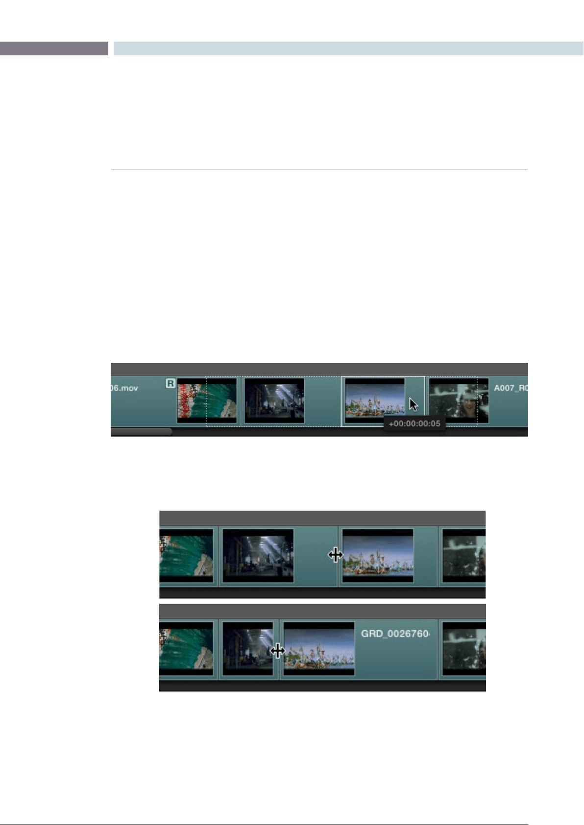
CHAPTER
CONFORM
CONFORM147
8
To move tracks up and down:
Right-click within the track you want to remove, and choose
Move Track Up or Move Track Down from the contextual menu.
That track, along with all clips on it, will be moved up or down
relative to the other tracks in the Timeline.
To trim clips and edit points in the Timeline, do one of the following:
Slip:
To slip a clip’s frame range without changing its position in
the timeline, click the Slip tool, and then click the clip you want
to adjust and drag to the left or right to “slip” a new range of
frames into the clip. A dashed overlay shows the total duration
of media available for you to slip with, which moves left and right
as you drag.
Roll: To roll an edit, moving the out point of the outgoing clip and the
in point of the incoming clip at the same time, click the Roll tool
and drag an edit point to the left or right.
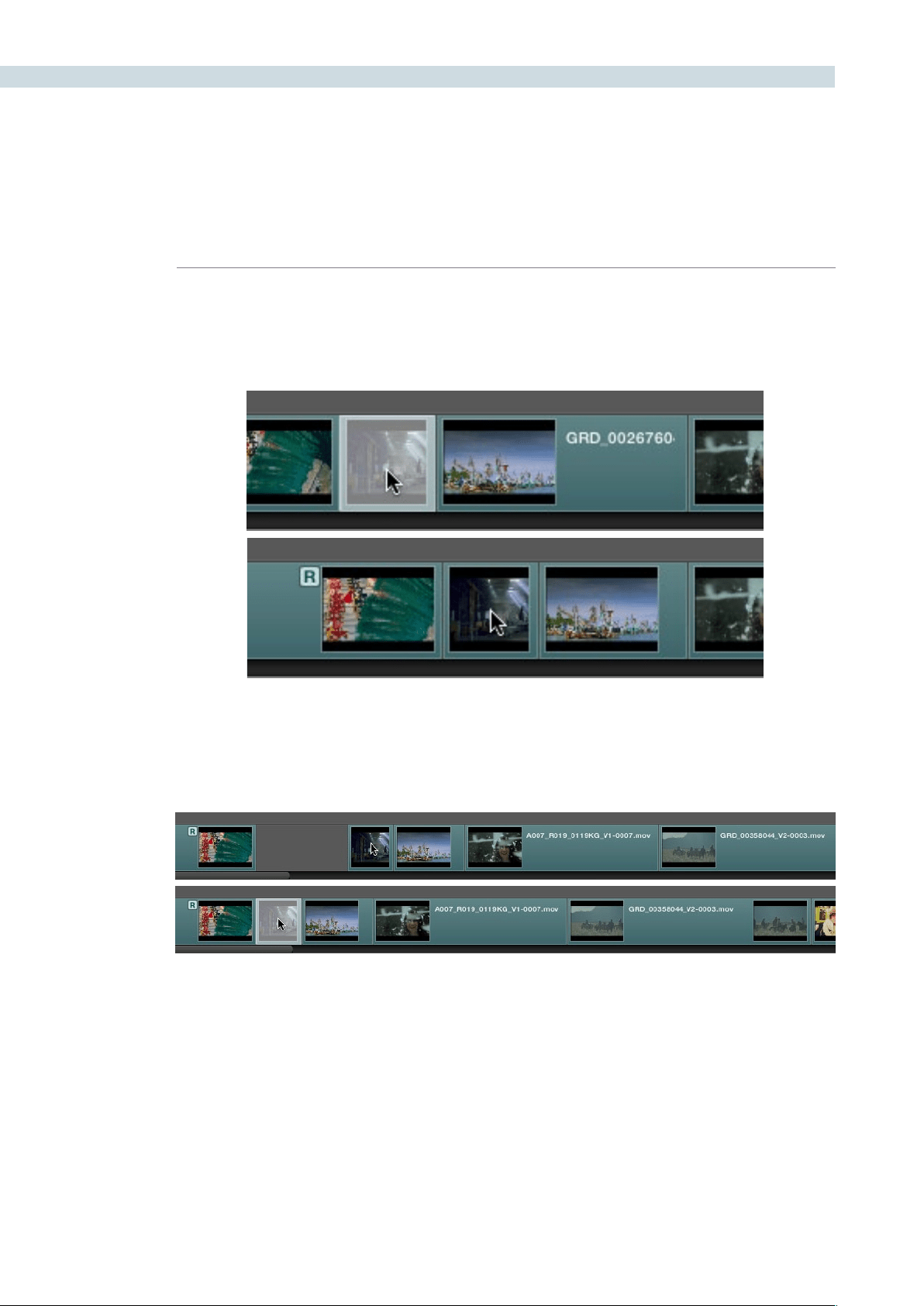
CONFORM 148
Slide: To slide an edit, moving that clip while simultaneously adjusting the
out point of the previous clip and the in point of the next clip to
accommodate the change, click the Slide tool and drag a clip to the
left or right.
Ripple clip: To ripple a clip, moving that clip while simultaneously moving every
other clip that comes after it back or forward on the Timeline to
make room, click the Ripple tool, and drag a clip to a new position in
the timeline.
Warning: While the Slip, Roll, and Slide tools will change the sync relationship of the clips you’re adjusting
with a matching soundtrack, the rest of the session won’t be affected. Using the Ripple tool can alter the
overall sync relationship of large portions of your session and its matching soundtrack, so you should
use it with extreme care in situations when you’re grading a locked program that’s having its audio
mixed at the same time.
Finding Media
DaVinci Resolve has three methods of locating clips, to help you troubleshoot problem sessions, or to
find media that you want to edit into a session differently.
CHAPTER
CONFORM
CONFORM149
8
To locate an event in the Conform EDL list:
•DragtheplayheadtointersectanyclipintheTimeline.
That clip’s corresponding event, or events if there is a transition, are automatically
highlighted in the Conform EDL list.
To locate a clip in the Media Pool:
•Right-clickanyclipintheTimeline,andchooseLocateinMediaPoolfromthe
contextual menu.
That clip appears highlighted in the Media Pool.
To locate a clip in the Master Session:
•Right-clickanyclipintheTimeline,andchooseLocateinMasterSessionfromthe
contextual menu.
That clip appears highlighted in the Master Timeline at the bottom of the Conform
page, and the Master Timeline playhead moves to intersect that clip.
Replacing Media in the Timeline
Often you have to replace one clip in a session with a different clip. For example, you may need to
replace an old version of an effects shot with a newer one that’s just been delivered, or an offline version
of a stock footage shot with a higher quality one.
1. Select the clip in the Media Pool that you want to swap into the Timeline.
2. Select the clip in the Timeline that you want to swap out.
3. Do one of the following:
•ClicktheReplaceClipbutton.
•Right-clicktheclipintheTimeline,andchoose“ReplaceWithSelectedClipinMedia
Pool” from the contextual menu.
The clip in the Timeline is now replaced with the clip from the Media Pool.
Tip: Another way of managing multiple versions of updated effects shots is to superimpose each
updated shot onto a new video track. That way you can keep older clips, along with their grades,
available in the session for later reference.
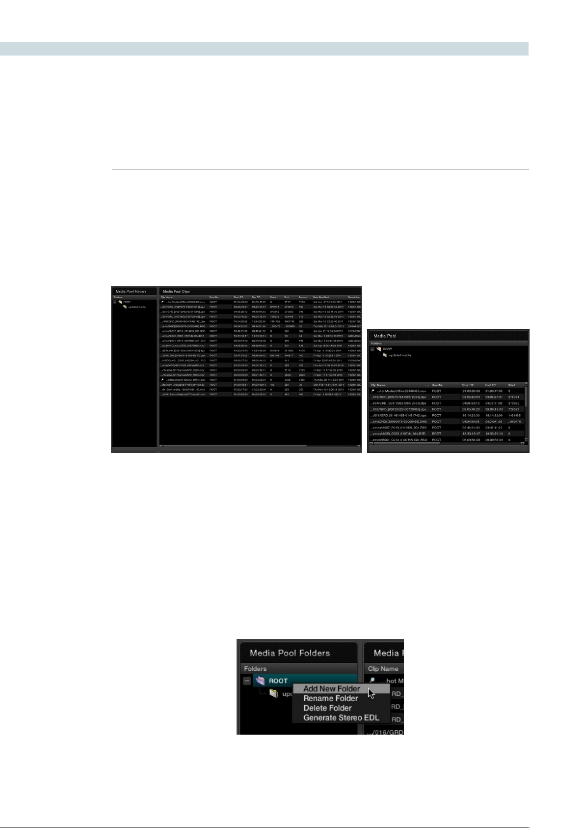
CONFORM 150
Reconform From Folders
The “Reconform From Folders” command is useful for helping you to manually choose what media,
in projects with multiple Media Pool sub-folders containing duplicate versions of clips, you want the
current session to be conformed to.
By default, all clips that you add to the Media Pool are stored in the Root folder, which can be seen in
the Media Pool Folders list of the Browse page, or at the top of the Media Pool in the Conform page.
However, you can create subfolders, located within the Root folder, for adding media that you want to
organize separately. For example, you could use subfolders to:
Add new versions of effects clips that you want to switch to.
Add online quality media with which to replace the offline quality media you’ve been working
with so far.
Add rescanned stock footage to replace the original temp clips you were using.
In all of these cases, a good way to organize new clips is to create a new Media Pool subfolder, by right-
clicking on Root and choosing Add New Folder, and then select the new folder when you add new clips
to the Media Pool.
The Media Pool Folders list in the Browse and Conform pages
Creating a new Media Pool subfolder
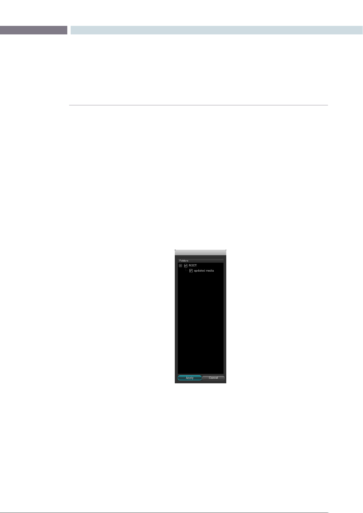
CHAPTER
CONFORM
CONFORM151
8
Once you’ve organized subfolders of clips in this way, you can use “Reconform From Folders” to select
which subfolders you want to conform to the current session. Keep in mind that for this to work, the
replacement media that you’re adding to these subfolders must have identical timecode and reel names
to the media that it’s meant to replace. If the timecode doesn’t match, you’ll need to manually replace
the clip in the timeline.
To reconform the clips in a sequence to specific clips within Media Pool subfolders:
1. Right-click anywhere in the Timeline, and choose Reconform From Folders from the
contextual menu.
A folders list dialog appears, with the Root folder displayed.
2.Clicktheplus(+)totherightoftheRootfoldertorevealallthesubfolders
contained within.
3. Turn on the checkboxes for the subfolders with media you want to conform the
session to, and turn off the checkboxes for subfolders with outdated media that you
want to ignore.
4. Click Apply
The Timeline is automatically updated to conform to the media contained within all
the subfolders you checked.
When you use “Reconform From Folders,” and two versions of a clip are both in selected folders, you’ll
have a reel conflict in the Timeline. By default, the clip that was most recently added to the Media Pool
is used by default, but you may want to manually resolve the reel conflicts just to be sure that you’re
using the correct version.

CONFORM 152
Force Conform
If you have a problem with a session such that an unconformed clip simply won’t automatically conform
to any clip in the Media Pool, even if you know the clip is there, you can use the Force Conform command
to force a clip in the session to conform to a clip of your choosing in the Media Pool.
To force conform an unconformed clip to another clip in the Media Pool:
1. Select a clip in the Media Pool.
2. Right-click an unconformed clip in the Timeline, and choose Force Conform from the
contextual menu.
The selected clip in the Timeline is conformed to the clip you selected in the Media
Pool in one of two ways:
•IftheselectedclipintheMediaPoolhasmatchingtimecodeandreelmetadata,then
the new clip is perfectly conformed as originally specified by the original EDL/AAF/
XML project data.
•IftheMediaPoolclipdoesnothavetimecodethatmatchestheselectedclipinthe
Timeline, then the new clip is conformed such that the first frame of the Media Pool
clip is aligned with the first frame of the reconformed clip in the session, and
occupies the same duration.
If you right-click that clip again, you’ll see that the box next to the Force Conform menu item is checked,
showing you that the clip has been force conformed to media that it wasn’t originally a match for.
Important: The clip you select in the Media Pool must be equal in length or longer then the clip you
select in the session for Force Reconform to work.
Working with Transitions
DaVinci Resolve supports a variety of different transitions besides the traditional cross-dissolve, allowing
for greater flexibility when finishing creative edits. The following are transition types that are supported
within Resolve:
Default
Center Wipe
Clock Wipe
Edge Wipe
Venetian Blind Wipe
Additive Dissolve
Cross Dissolve
Dip to Color Dissolve
Cross Iris

CHAPTER
CONFORM
CONFORM153
8
Diamond Iris
Oval Iris
Other
The following procedures describe how to work with transitions in DaVinci Resolve.
Methods of working with transitions:
To add a transition:
Drag one clip so it overlaps another. A transition appears where
the clips overlap.
To add a transition to the beginning or end of a clip:
Right-click a clip in the Timeline, and choose Add Start Transition
or Add End Transition from the contextual menu. Start and End
transitions function as fade from and fade to black.
To change a transition type:
Right-click a transition in the Timeline, and choose a different
transition type from the Transition Effect submenu.
To remove a transition:
Right-click a transition in the Timeline and choose Delete Transition
from the contextual menu. Or, drag one of the overlapping clips
away from the other until they no longer overlap, and the transition
will be gone.
Working With Effects
While traditionally effects weren’t within the domain of color grading software, today a wide variety
of effects are added to programs during the initial edit, and many of these can now be carried over
into DaVinci Resolve, including composite modes, opacity settings, linear speed changes, and different
video transitions.
Composite Modes
Composite Modes are effects that use various mathematical operations to blend one superimposed
clip with another. When you import XML project files, Resolve also imports whatever Composite modes
were used by clips in the original Final Cut Pro sequence. If necessary, you can change a clip’s Composite
mode to one that will work better with whatever grade you’re creating.
Furthermore, you can add composite modes to clips that didn’t originally have one, adding new effects
of your own. For example, you could superimpose a clip against itself and use a composite mode to
combine two differently graded versions of the same clip.
Or, you could import an entirely different clip and use composite modes to create interesting or utilitarian
blends between the two. For example, the Add and Overlay composite modes can be useful for creating
glow effects, while Subtract and Difference can create more surreal effects.

CONFORM 154
In more practical examples for titling, if you superimpose a clip that consists of white text against black
and set its Composite Mode to Screen, the black background disappears and the white text is combined
with the underlying clip. Similarly, if you superimpose and Multiply a clip consisting of black text against
a white background over another clip, the white background disappears and the black text is combined
with the underlying clip.
There are ten Blend Modes to choose from:
Normal
Add
Subtract
Difference
Multiply
Screen
Overlay
Darken
Lighten
Unknown
Working with composite modes is simple.
To set or change a composite mode for any clip:
Right-click the clip you want to change the the transfer mode
of, and choose one of the options from the Composite Mode
submenu.
To turn composite modes off:
Right-click the clip you want to turn the composite mode off of,
and choose Normal from the Composite Mode submenu.
Note: Composite modes are designed to be used on clips that are superimposed over other clips
in the Timeline. If you apply a composite mode to a clip that’s not superimposed, you may get
unexpected results.
Speed Effects
DaVinci Resolve is capable of reading linear speed effects from imported EDL, AAF, and XML projects,
and playing clips at the specified speed from within Resolve. Resolve is not compatible with non-
linear speed effects, and there is no frame blending or interpolation. For this reason, you may find it
advantageous to render clips with speed effects as self-contained media files in your NLE or compositing
software before sending the project to Resolve for grading, in order to obtain the best quality.
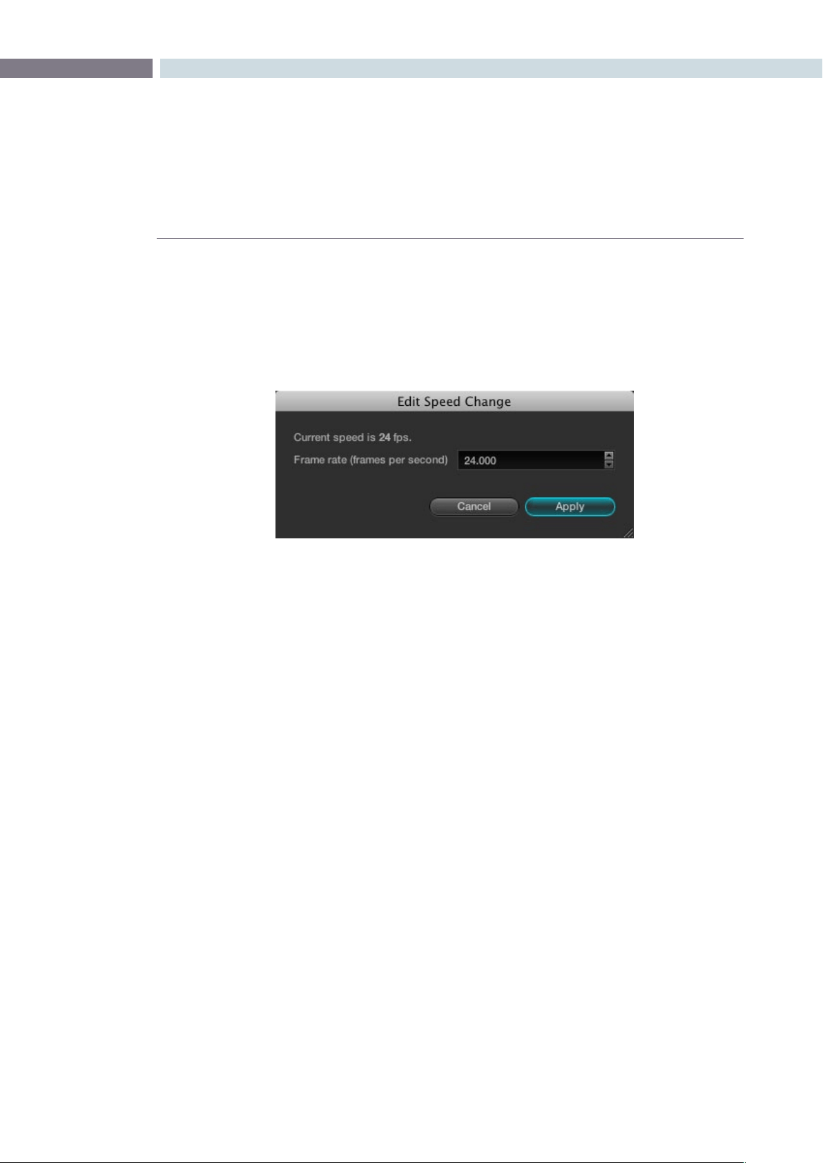
CHAPTER
CONFORM
CONFORM155
8
To change a clip’s speed:
1. Right-click a clip in the Timeline, and choose Change Clip Speed from the
contextual menu.
2. Enter a new frame rate into the Frame rate field, or click the Up/Down arrow buttons to
change the value in one frame increments.
For example, in a project set to 24 fps, to set a clip to 50% speed, change its frame rate
to 12. To set a clip to 200% speed, set the frame rate to 48.
3. Click Apply.
The speed of the clip changes to reflect the new frame rate, however the duration and
position of the clip remain unchanged.
Syncing Sessions to Audio
DaVinci Resolve lets you synchronize a session to audio so you can grade it within context to the
program’s soundtrack, host client review sessions with synced audio, or output with audio to tape.
Sessions can be synced to one of two different sources of audio:
A timecode-controllable audio playback device, such as a DAT deck.
A single 16 or 24-bit/48KHz AIFF or WAV file on an accessible volume.
Here are all of the procedures for audio synchronization.
To synchronize a session to audio from a timecode controllable playback device:
1. Right-click anywhere within the Timeline, and choose Audio Options from the
contextual menu.
2. Open the LTC tab, and enter the starting timecode value of the recorded audio on tape
you’re syncing into the “Start Timecode” fields.
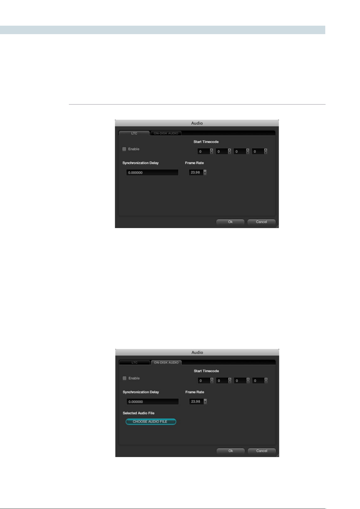
CONFORM 156
3. Set a Synchronization Delay to account for any latency between Resolve and the audio
playback device, and choose the proper frame rate.
4. When you’re finished, turn on the Enable checkbox and click OK.
Once synchronized, LTC timecode output from your Resolve workstation’s video I/O
card will lock and synchronize the external audio device whenever you play the session.
It’s vital to make sure that the audio frame rate is set correctly or you will experience
audio/video sync slippage.
To synchronize a session to a WAV or AIFF audio file:
1. Right-click anywhere within the Timeline, and choose Audio Options from the
contextual menu.
2. Open the On-Disk Audio tab and click Choose Audio File.
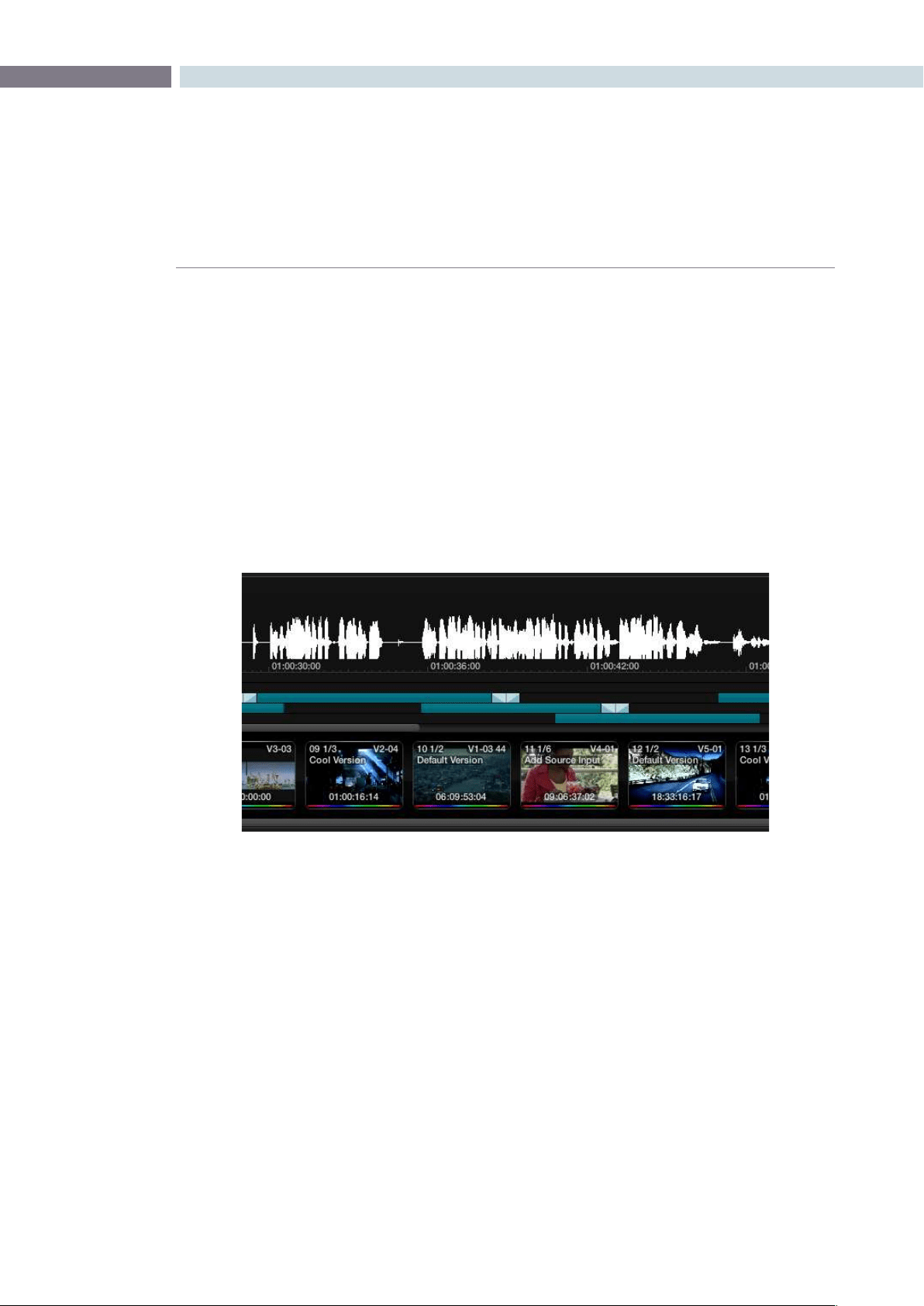
CHAPTER
CONFORM
CONFORM157
8
3. When the Choose Audio File window opens, located and select the audio file you want
to sync the current session to, and click Open.
4. If necessary, change the Start Timecode fields to account for any offset between the
start frame of the session and the start frame of the audio in the file, and choose the
proper frame rate.
5. Turn on the Enable checkbox, and click OK.
To view the waveform of a synchronized audio file in the Color Page:
•Right-clickthemini-TimelineandchooseShowAudioInfofromthecontextualmenu.
The audio waveform appears in a track above the mini-Timeline. To hide it again, right-
click in the audio track and choose Hide Audio Info.
To change the offset between video and audio in the Color page:
1. With the audio waveform track open above the mini-Timeline, right-click in the audio
track and choose Adjust Audio Offset.
2. When the audio offset window appears, choose values for the Hour, Minute, Second,
Frame, and SubFrame fields that will eliminate the offset between the visuals and the
audio, and click Apply.
3. Play the program, and if the audio is still out of sync, repeat from step 1.

CONFORM 158
When you open the Offline tab of the Conform page, you switch into a mode where you can compare
an “offline-identified” media file to a session such that both playheads are locked or “ganged” together.
As you play the session, the media file plays as well.
An offline-identified clip must be added to the Media Pool specifically as an “offline” clip, and is
associated with a particular session by being chosen from a pop-up menu in the Offline Clip column of
the Timeline Management list.
The idea is that if your client exports a flattened version of their edited sequence at the same time as
they export the EDL, AAF, or XML project file they want graded, then you can compare the project data
that’s imported into Resolve to the actual video of the offline version of the program that the editor had
created.
Note: Often, the flattened version of the program you’re given uses a low-quality codec and contains
effects and color correction that’s not final, which is why it’s called an offline clip. These clips are imported
in a particular way in the Media Pool.
There are two reasons for comparing an offline-identified clip to a session:
Verifying the clip order: If you’re unsure whether you’ve properly resolved reel conflicts or
other problems that occurred while you were conforming a session,
you can compare each edit to the offline version of the program to
spot problems and identify the proper media that should correspond
to any clip.
Recreating effects: If there are offline effects such as temporary grading done in an NLE
or pan and scan transforms that the client would like to recreate or
have you reference, the Offline/Timeline mode lets you examine the
editor’s version of an effect from within Resolve.
Setting Up an Offline/Timeline Comparison
Here’s how to compare offline-identified clips to a session.
To compare a session with an offline-identified media file:
1. Open the Browse page, and use the Media Storage browser and Clip Details list to find
the flattened “offline” version of the edited program that you want to use for comparison.
2. Right-click the “offline” media file and choose Add as Offline Clip from the
contextual menu.
The clip is added to the Media Pool as an “offline-identified” clip, with a magnifying-glass
icon to the left of its name.
Making Comparisons in Offline/
Timeline Mode
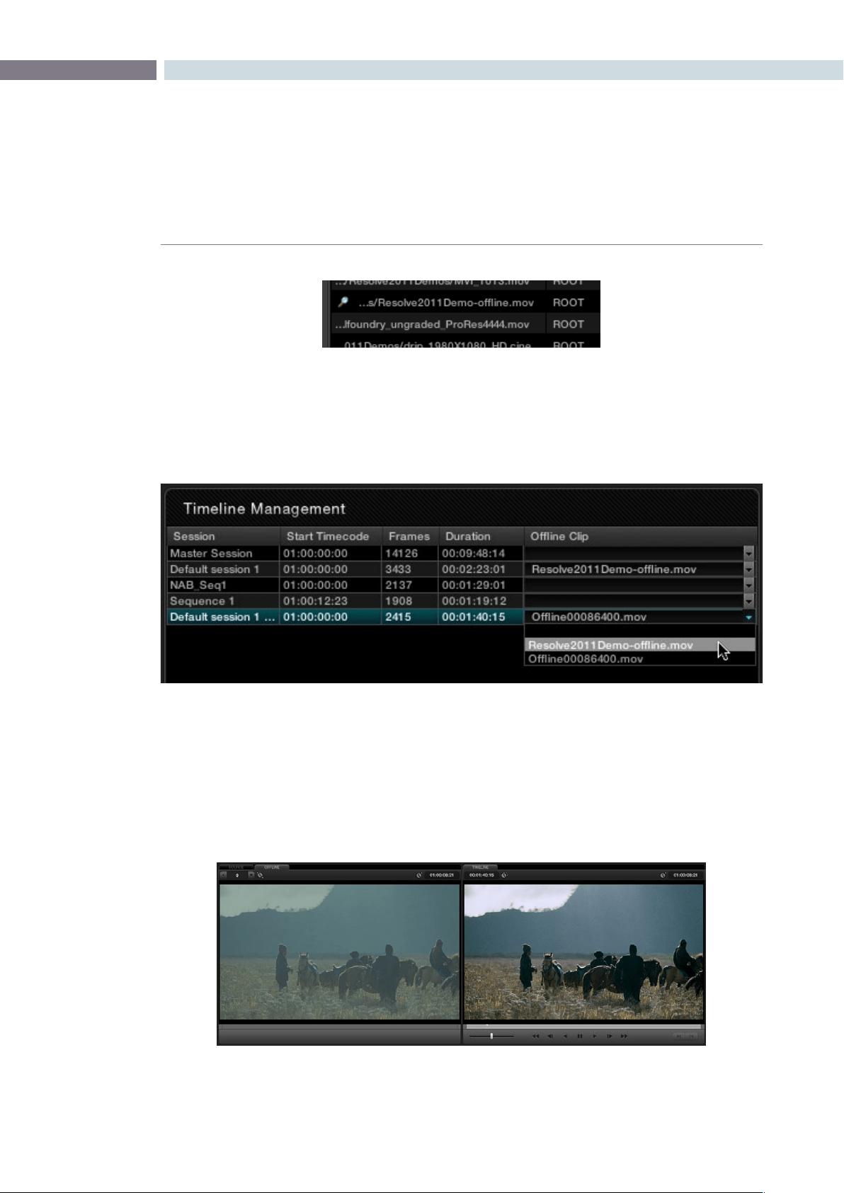
CHAPTER
CONFORM
CONFORM159
8
3. Open the Conform page, select the session you want to review, then click the pop-up
menu in the Offline Clip column all the way to the right of the Timeline Management list,
and select the offline-identified clip that you want to compare that session to.
4. Click the Offline tab, to the right of the Source tab.
The offline-identified clip appears within the Offline tab, and plays back in sync with the
Timeline. If your clips are graded, you can see the comparison between the state of each
clip in the offline-identified clip, and the graded session clip.
Offline identified clips appear with a magnifying glass icon
to the left of their path and name in the Media Pool
Choosing one of two available offline-identified clips from the Offline Clip column’s
pop-up menu in the Timeline Management list
The Conform page in Offline/Timeline mode
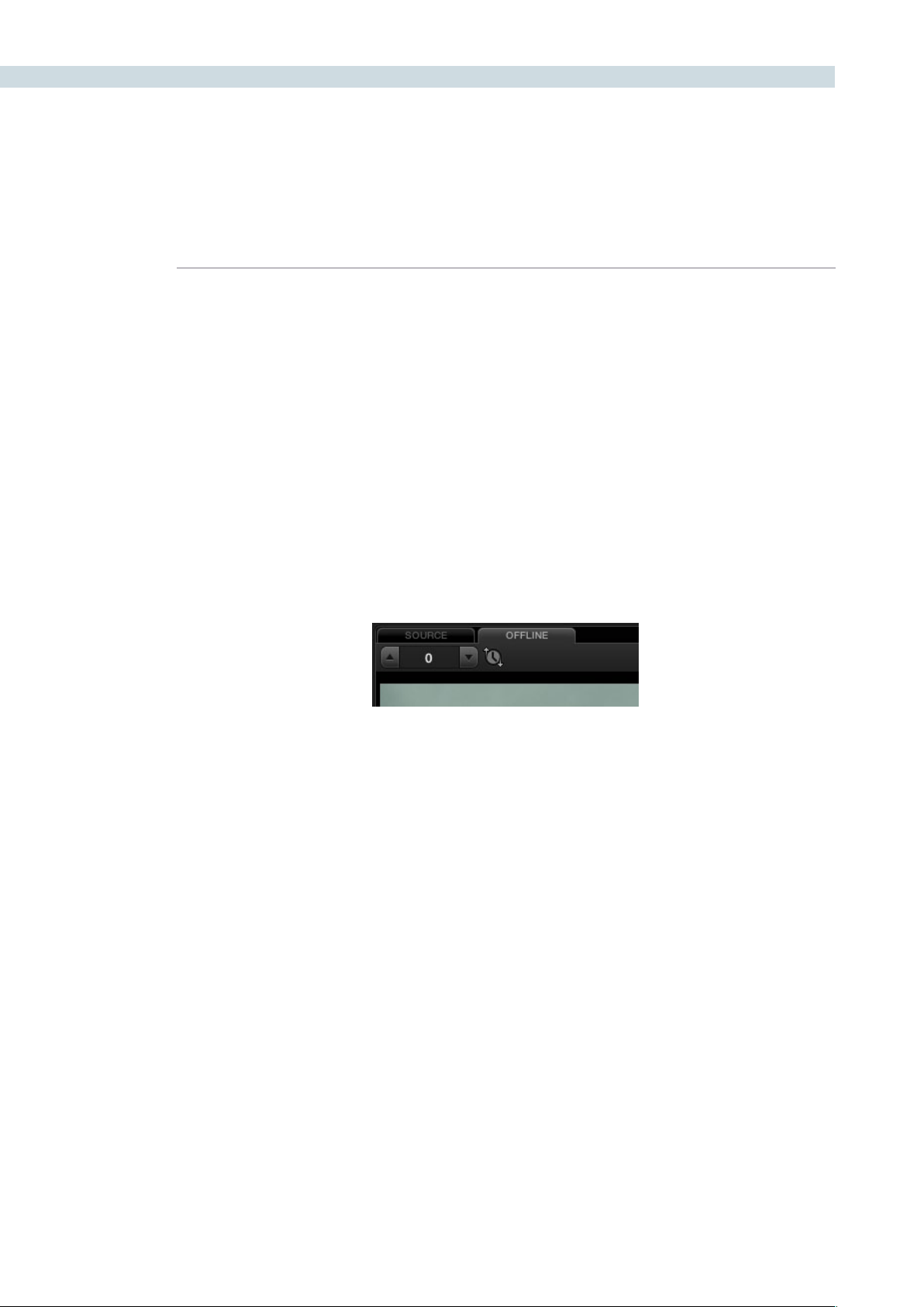
CONFORM 160
Adjusting the Offline/Timeline Sync Offset
Ideally, the starting timecode of the offline-identified clip should be identical to that of the session you’re
comparing it to. However, it may happen that the timecode of each is offset by several minutes, seconds,
or frames.
To adjust the sync offset between the offline clip and your session:
1. In Offline/Timeline mode, play the session until you find an easy-to-identify sync frame,
perhaps the first frame of a clip with unique visuals. Note the playhead’s timecode.
2. Scrub the playhead forward until the frame you found in step 1 is visible in the Offline
tab, and note the second playhead value.
3. Subtract the first timecode value from the second timecode value, and enter the
difference into the sync offset field, or click the up/down buttons to adjust sync one
frame at a time if the difference is small.
The frames shown in the Offline tab and Timeline tab should now be identical. If not,
keep adjusting the offset field until they are.
Note: If the Offline tab continues to only display black, it might be because the timecode is completely
unmatched to the EDL. You might need to right-click the offline clip in the Media Pool and choose
Change Timecode from the contextual menu to open the Change Timecode dialog, and change the
timecode to accurately match your session.
Alternate Online and Offline Comparison Modes
The standard comparison between the Online and Offline viewers will show the two images side by side,
however if you right click within the Offline Viewer you can select one of the alternate display options.
Horizontal wipe, vertical wipe and mixed will sometimes show errors more apparently than side by side.
For the wipe modes you can use your mouse to move the position of the wipe.
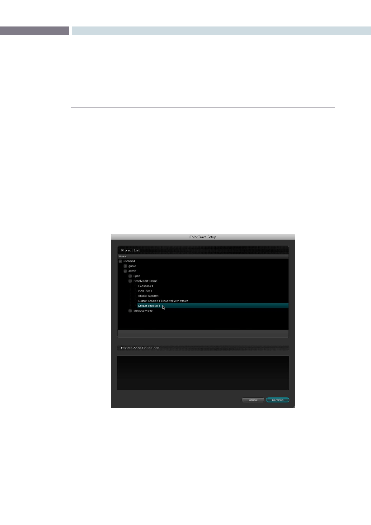
CHAPTER
CONFORM
CONFORM161
8
ColorTrace™ is a key feature of DaVinci Resolve, which lets you copy grades quickly and easily from the
clips of one session to those within another, based on the source timecode of each clip, or using clip
names when in Automatic mode.
Important: During ColorTrace™ operations, only the default grade is copied from one session to another.
All other grade versions are ignored.
To use ColorTrace™:
1. Open the Conform page and select the session you want to use ColorTrace™ with in
the Timeline Management list.
2. Right-click anywhere within the timeline, and choose ColorTrace™.
The ColorTrace™ Setup window appears, which shows every database, user, project,
and session within a single hierarchical list.
3. Using the Project List, select the specific session you want to copy grades from.
You’llneedtoclickthesmall+totheleftofthedatabase,username,andprojectthat
contains that session to select it.
4. Click Continue.
The ColorTrace™ window appears.
Using ColorTrace™ to Apply Grades From
One Project to Another
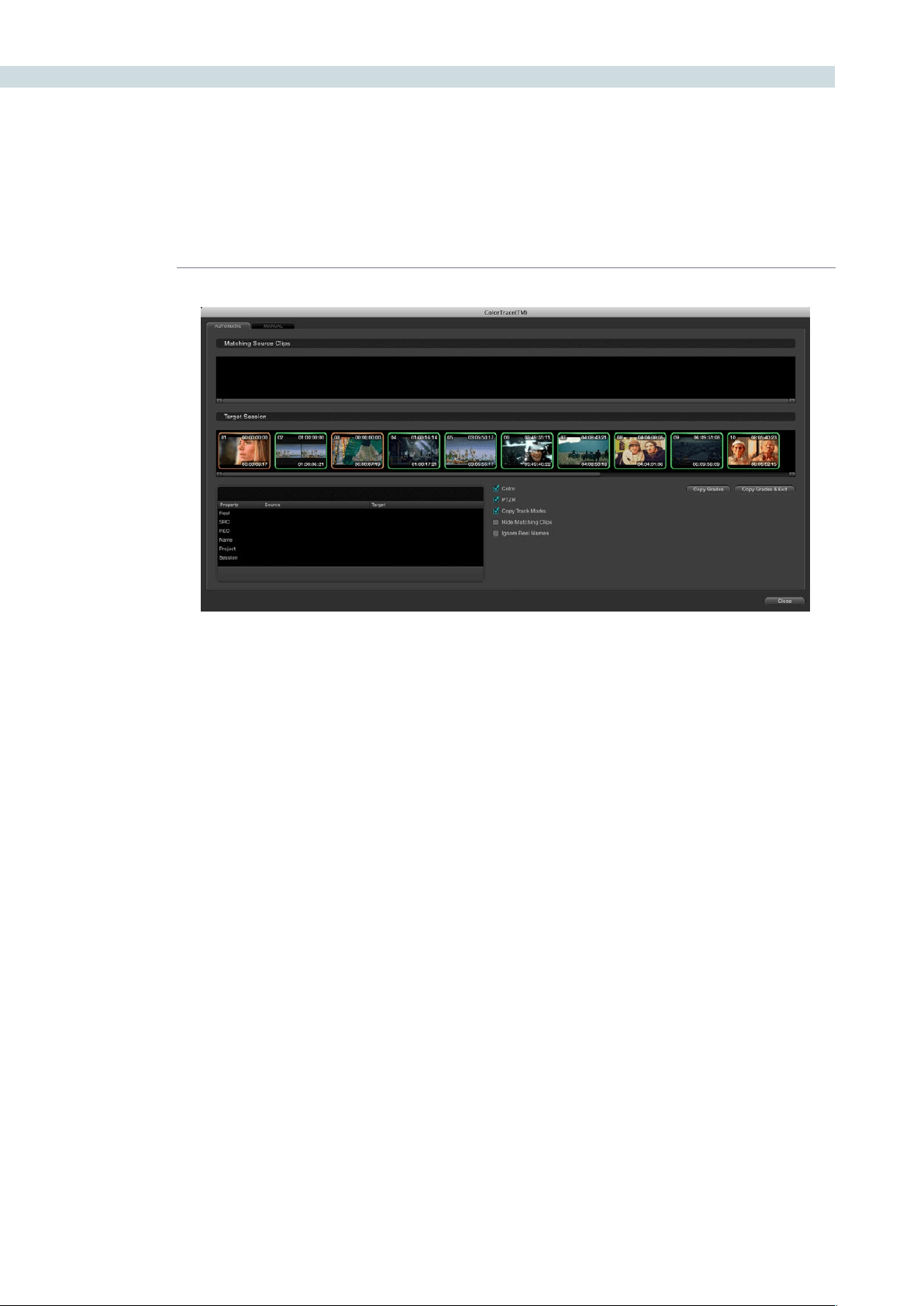
CONFORM 162
5. Choose which mode to work in by clicking the Automatic or Manual tabs:
•InAutomaticmode,ColorTrace™automaticallysearchesformatchingclipsbetween
the selected session and the current session. Each clip is color-coded depending on
the correspondence that’s been identified.
•InManualmode,youcopygradesyourself,usingtheCopyandPasteprocedures,or
by dragging and dropping using your mouse.
The ColorTrace™ window is complex; details about the operation of each mode are
covered separately in the following sections.
6. When you’re finished using ColorTrace™, click Close.
Using ColorTrace™ in Automatic Mode
In Automatic mode, ColorTrace™ automatically finds the correspondences between clips in the selected
session that you want to copy grades from (the Source session), and those in the current session that
you want to copy grades to (the Target session).
`
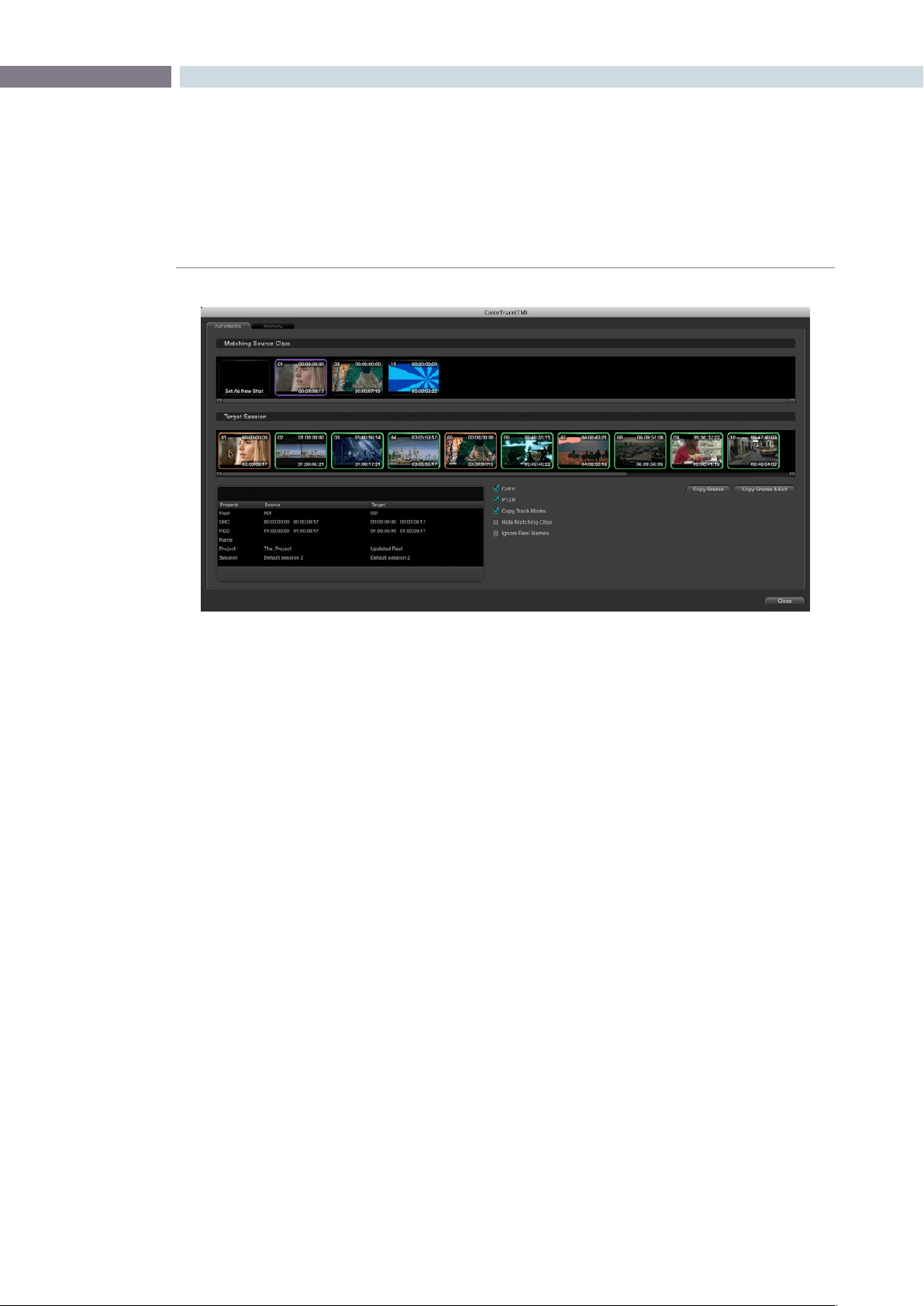
CHAPTER
CONFORM
CONFORM163
8
Each clip in the Target Session thumbnail timeline is outlined with a color that indicates its status.
Green: A perfect match has been found.
Orange: Due to overlapping timecode and reel names, multiple
correspondences have been found (similar to a reel conflict), and
you must select the correct one for each clip.
Red: No match was found at all.
In Automatic mode the correspondence between each clip in the source session and each clip in the
Target session should be automatically made. However, overlapping timecode and reel names can
cause problems. The other controls in the ColorTrace™ window help you deal with the subset of clips
can’t be automatically matched, or are matched in error. These controls are:
Target Session timeline: Shows each clip in the session you want to copy grades to, color-
coded according to how good a match it is.
Matching Source Clips list: Shows a scrollable collection of thumbnails that might correspond
to the selected clip in the Target Session timeline.
Clip Info pane: Displays two columns of properties for the source clip and the target
clips that you’ve selected. These properties include the Reel, Source
timecode, Record timecode, clip name, project names, and session
names of each clip, for easy comparison.
The ColorTrace™ window shown in Automatic mode, with a selected clip in the
Target Session timeline revealing a number of different possible
correspondences in the Matching Source Clips timeline.

CONFORM 164
Color/PTZR/Copy Track Marks checkboxes:
Turn off the checkboxes of any clip characteristics that you don’t
want to copy as part of the ColorTrace™ operation. For example, if
youwanttocopygrades,butyoudon’twanttocopyPTZRorTrack
Marks (keyframes), you can turn those off.
Hide Matching Clips: Hides all clips which have been successfully matched, and only show
the clips with multiple or no matches. This lets you focus on the
subset of problem clips within a potentially long timeline.
Ignore Reel Names: If you believe the reel names are in error, you can turn this checkbox
on to ignore them, matching all Source and Target clips by
timecode alone.
Copy Grades: Copies the matched Source grades to each green and purple
Target clip.
Copy Grades & Exit: Once you’ve finished making all the grade matches you can, click
this button to copy the matched Source grades to each green and
purple Target clip, and close the ColorTrace™ window.
Here’s how to use these controls to sort out which Source clips to copy from for each orange and red
Target clip in the Target Session timeline.
To manually choose which Source grades should be copied to which Target clips:
1. Click any clip thumbnail in the Target Session timeline.
A collection of clips with overlapping timecode and reel names appears. If you want to
ignore the reel names because you believe they might be in error, turn on the Ignore Reel
Names checkbox.
2. If a comparison of the Source and Target thumbnails doesn’t make the choice obvious,
then click any of the source clips to view its metadata in the Source/Target columns
for comparison.
3. Once you’ve decided on a clip correspondence, double-click the Matching Source Clip
thumbnail you want to copy from. Or, if no clip in the Matching Source Clip pane is a
good match, double-click the “Set As New Shot” box.
The Source and Target thumbnails both turn purple, to show that you’ve created
a correspondence.
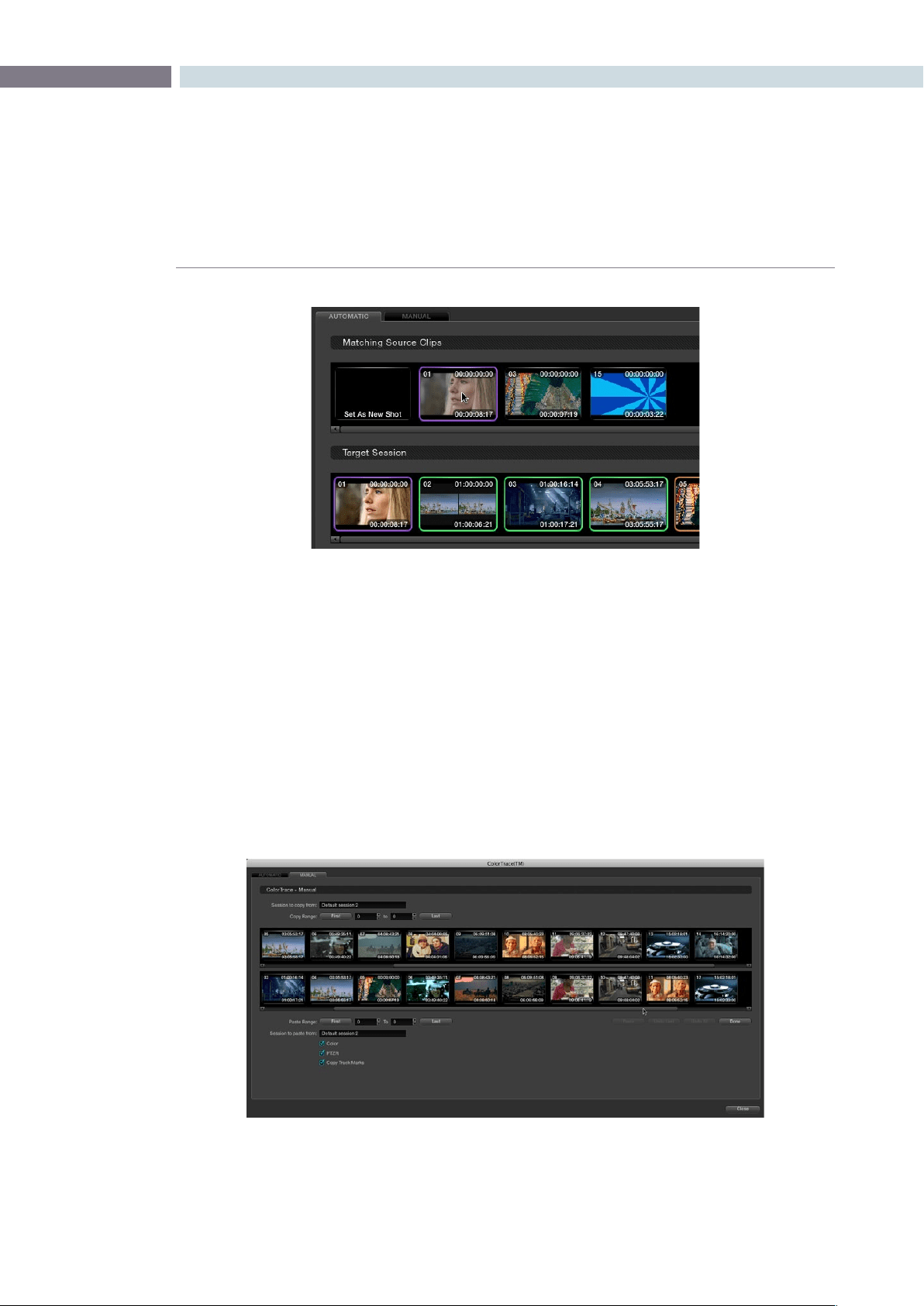
CHAPTER
CONFORM
CONFORM165
8
Continue working your way through every thumbnail with Orange and Red Xs until
you’ve found matches for every clip in the session for which it’s possible.
4. When you’re finished, click Copy Grades & Exit.
Using ColorTrace™ in Manual Mode
Manual mode is ideal for situations where you want to copy grades between programs with clips that
have no timecode or reel name correspondence at all. The Manual ColorTrace™ interface is designed
to let you move through two different sessions, either a clip at a time, or in matching multiples of clips,
copying grades from the source session to the target session.
Purple thumbnails in the Target Session timeline indicate
that you’ve made a manual match
The ColorTrace™ window shown in Manual mode

CONFORM 166
For example, if you’re trying to copy grades from a session that was conformed from individual media
files, to another session that was conformed from a flattened master media file, you can use the
ColorTrace™ Manual mode to accomplish this.
The manual interface consists of two sets of controls that correspond to the source session labeled
“Session to copy from”, and the target session labeled “Session to past to”. The general idea is that you
move through both sets of timelines one clip at a time, or in matching multiples of clips at a time, and
copy grades from the “Copy from” session to the “paste to” session.
Manual mode has the following controls:
Copy Range controls: Two fields show the range of clips in the current selection that you’ll
be copying from, referred to by their numeric position in the Source
session timeline. You can change the range numerically by either
entering new numbers in the fields, or by using the up/down arrow
buttons to alter the value by one. The First button automatically adds
all clips from the first one in the session into the current selection.
The Last button automatically adds every clip going to the last one
in the session to the current selection.
Source session timeline: Shows all clips in the source session you selected; the clips you’re
copying grades from. Click any one clip thumbnail to select it, or
click a thumbnail, and then shift-click another thumbnail to select a
contiguous range of clips. You cannot select a noncontiguous range
of clips.
Target session timeline: Shows all clips in the target session you selected; the clips you’re
pasting grades to. Selecting clips works identically as with the
Source session timeline.
Paste Range controls: Two fields show the range of clips in the current selection that
you’ll be pasting to, referred to by their numeric position in the
Source session timeline. All controls work identically to the Copy
Range controls.
Color/PTZR/Copy Track Marks checkboxes:
Turn off the checkboxes of any clip characteristics that you don’t
want to copy as part of the ColorTrace™ operation. For example, if
youwanttocopygrades,butyoudon’twanttocopyPTZRorTrack
Marks (keyframes), you can turn those off.
Paste button: Once you’ve selected one or more Source clips and a matching
numberofTargetclips,clickingPastecopiesthegrades,PTZR
settings, and marks, depending on the corresponding checkboxes.
Undo Last: Lets you undo the most recent paste action.
Undo All: Lets you undo all paste actions in Manual mode.
Done: Finishes the operation and closes the ColorTrace™ window.

CHAPTER
CONFORM
CONFORM167
8
If you’re cherry-picking individual grades from one session to paste into shots in another, you can copy
grades one at a time.
To copy one source grade to one target clip:
•Click a thumbnail in the Source session timeline (on top) to copy from, then click a
thumbnail in the Target session timeline (on the bottom), and click Paste.
You can also simultaneously copy the grades of entire scenes of clips from one session to another. For
example, if you’re copying grades from an originally graded session to a re-edited version of the same
program, you can copy every grade from a 10-clip scene in the Source session to the same 10 clips in
the Target session which have been pushed back later in the timeline.
To copy a group of source grades to a group of target clips:
1. Choose a continuous range of Source clips by doing one of the following:
•Clicktherstclipintherange,andthenShift-clickthelastclipintherange.
•Entertheclipnumberoftherstclipintheleft“CopyRange”eld,andthenenter
the clip number of the last clip in the right field.
•Clickaclip,andthenclickFirsttoselecteveryclipfromthatonetotherstclipin
the session.
•Clickaclip,andthenclickLasttoselecteveryclipfromthatonetothelastclipin
the session.
2. Choose a continuous range of Target clips by using the same procedures as in the
previous step, but using the “Paste Range” controls.
IMPORTANT: You must select the same number of Target clips as you did Source clips
for the Paste button to become enabled.
3. When you’ve made your selections, click Paste.
The grade settings from the source clips are pasted to the destination clips, in order. In
other words, if you copy from clips 27, 28, and 29 to clips 4, 5, and 6, then grade 27 is
copied to shot 4, grade 28 is copied to shot 5, and grade 29 is copied to shot 6.
Importing CDL Data Using ColorTrace™
The ColorTrace™ CDL command lets you import ASC CDL file formats from other applications into
DaVinci Resolve.
There are three supported file formats:
CMX EDL: An EDL with comments referring to CCC/CDL XML files, or even
Slope, Offset, and Power (SOP) data within the comment area.
CCC and CDL XML: A file format that contains various color correction looks, and
even references.

CONFORM 168
To import CDL data into DaVinci Resolve:
1. If you’re importing CCC/CDL XML correction looks:
•OpentheGallerypage,right-clickanywherewithintheStillstab,andchoose
“Import” from the contextual menu.
•WhentheImportStillsdialogappears,opentheCDL/CCCles.Whentheseare
finished importing into the Gallery, an ASC logo will appear along with them.
2. Open the Conform page and select the session you want to use ColorTrace™ with in
the Timeline Management list.
3. Right-click anywhere within the timeline, and choose ColorTrace™ CDL.
4. Select an EDL using the Select EDL dialog, and click Open.
5. Select its corresponding CDL and CCC files using the Select CDL Files dialog. If there are
no CDL or CCC files which is the case if there are inline SOP comments within the EDL,
you should click cancel.
6. Using the ColorTrace™ With CDL window, copy the Source grades from the CMX EDL/
CCC & CDL XML files to the Target session.
At this point, the ColorTrace™ window works identically as previously described.
For formatting reference, here are some examples of CMX, CCC and CDL files.
Example CMX EDL File
TITLE: Final EDL
FCM: NON-DROP FRAME
010 001 V C 01:19:28:16 01:19:28:16 01:00:41:18 01:00:42:18
*ASC_CC_XML test_cc.102
011 001 V C 00:00:00:00 01:19:28:16 01:00:42:18 01:00:43:18
*ASC_SOP (0.9 1.2 0.5)(0.4 -0.5 0.6)(1.0 0.8 1.5)

CHAPTER
CONFORM
CONFORM169
8
Example CCC file:
<ColorCorrectionCollection xmlns:”urn:ASC:CDL:v0.5” >
<InputDescription>
test corrections for ref_input_image.1920
</InputDescription>
<ViewingDescription>
for mathematical analysis only
</ViewingDescription>
<ColorCorrection id=”test_cc.100”>
<SOPNode>
<Description> for ref_output_image.0100 </Description>
<Slope> 1.0 1.0 1.0 </Slope>
<Offset> 0.0 0.0 0.0 </Offset>
<Power> 1.0 1.0 1.0 </Power>
</SOPNode>
</ColorCorrection>
<ColorCorrection id=”test_cc.101”>
<SOPNode>
<Description> for ref_output_image.0101 </Description>
<Slope> 1.0 1.5 0.6 </Slope>
<Offset> 0.0 -0.1 0.01 </Offset>
<Power> 1.0 1.5 0.5 </Power>
</SOPNode>
</ColorCorrection>
</ColorCorrectionCollection>
Example CDL file:
<ColorDecisionList xmlns=<94>urn:ASC:CDL:v0.5<94> >
<InputDescription> GeneralProducts M1 std thru GP M1 LUT4 </InputDescription>
<ViewingDescription> GP P1, DCI P3, Pathe color emul </ViewingDescription>
<ColorDecision>
<MediaRef ref=<94>/some/Project/frame%250900-0954%5B.dpx<94>/>
<ColorCorrection id=”cc03340”>
<SOPNode>
<Description>change+1red,contrastboost</Description>
<Slope>1.2 1.3 1.4</Slope>
<Offset>0.3 0.0 0.0</Offset>
<Power>1.0 1.0 1.0</Power>
</SOPNode>
</ColorCorrection>
</ColorDecision>
</ColorDecisionList>

CONFORM 170
Calculating CDL Functions
In order to turn the SOP values into a primary correction, the following math is used by
DaVinci Resolve:
Output=(Input*Slope+Offset)
Power
Output refers to the final grade. Input is the value of each pixel within each color channel, on a
scale from 0-1) The detente value for Slope is 1. The detente value for Offset is 0. The detente
value for Power is 1.


Color
9
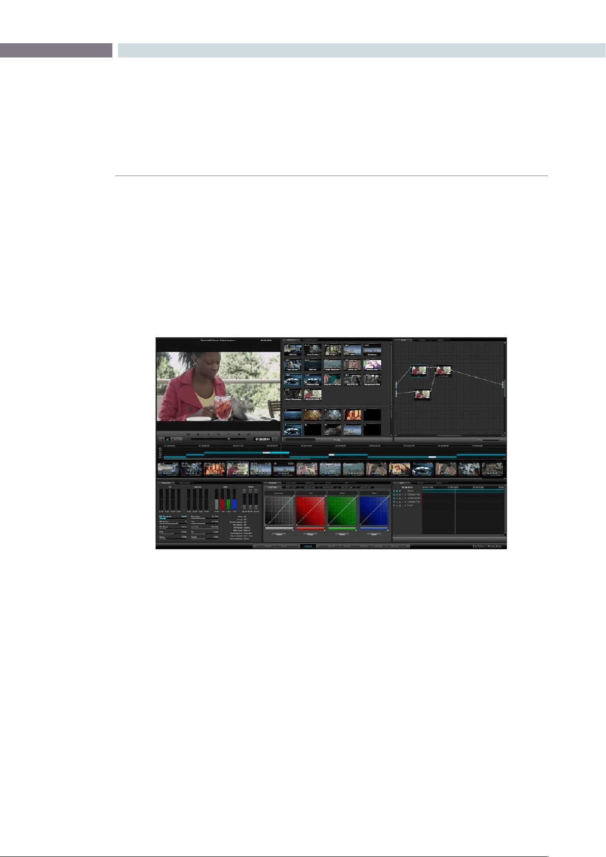
CHAPTER
COLOR
COLOR173
9
The Color screen is essentially the heart of the DaVinci Resolve system.
In addition to basic color correction you also have the option of applying a PowerWindow or even Blur,
Pro-Mist and Aperture Correction Effects to each clip. The color enhancement process is clip based and
centers on the usage of nodes. Each corrector node can be considered a full featured color corrector
and multiple nodes can be applied in either Parallel or Serial, depending upon the desired correction.
The Color Enhancement screen has a number of areas of display that all work together. From left to right
they are: the Viewer with Transport Controls, Stills display, and Node graph. Under these displays is the
track timeline and the thumbnails timeline. Below that are the primary controls, secondary controls, and
the dynamics timeline.
Most of the controls are active by both mouse and control panel operation. For example, clicking and
dragging the controls with the mouse within the Primary Color Correction window will carry out color
enhancement adjustments. The DaVinci Resolve control surface provides concurrent control over
many functions.
Color
Color screen

COLOR 174
Located at the upper left of the Color screen, the Viewer displays the current clip and the current frame.
At the top of the Viewer in the center of the window bar, the Project and Session names are shown. To
the left of this is a GPU status display and the Playback Speed display in frames per second. DaVinci
Resolve uses GPUs for image processing, so the GPU status indicates the percentage of use that the
current color correction demands of the GPU. A full green indication shows there is plenty of GPU
headroom. As the GPU processing resources are used by additional color correction the green bars will
reduce. A flashing red indication means that the GPU is unable to consistently process the correction in
real time. Ultimately, as you add a larger number of corrections, you will reach the real time limit of the
GPU and DaVinci Resolve will then play back at a slower than selected playback speed.
Youcancontinuewiththeslowerthanrealtimeoperation,select‘OntheFlyProxy’soDaVinciResolve
can generate proxy source images in real time, or, you can select Render Cache to cache the clip.
In cache mode, once the clip has been played once it will be cached for real time playback. More
information on Render Cache options appears later in this chapter.
On the bottom right of the Viewer window is the primary timecode display for the clip being played.
Justlikewiththetopdisplay,youcanchangetheinformationshowninthetimecodesectionofthe
Viewer area by clicking on the timecode display with the mouse to toggle the display between the five
options as described above. To the right of the primary timecode display is the ’Clip Loop’ selection
button. Enable this for looped clip playback. Click again to disable. You can also select ’Loop’ from the
DaVinci Resolve control surface.
Viewer
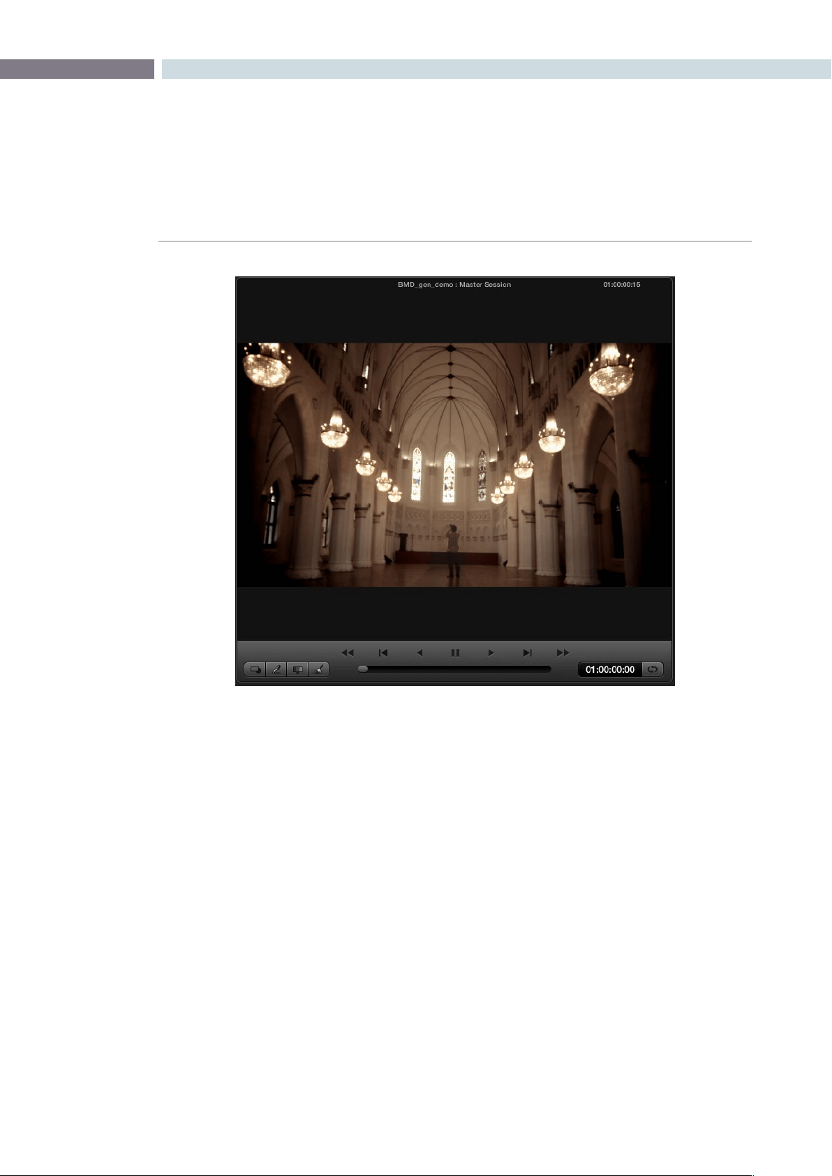
CHAPTER
COLOR
COLOR175
9
Located at the bottom of the Viewer display are controls for playing the clip Forward, Reverse, Fast
Forward, Fast Reverse, Step Forward, and Step Reverse. These are accessed by clicking on the
appropriate control with the mouse or by using the Transport Controls on the DaVinci Resolve control
surface, or a standard keyboard. Below the transport controls, is a scroll bar for scrolling through a clip
by dragging the bar back and forth using a mouse.
At the bottom left of the Transport Controls there are four buttons. These viewing options alter what
is being displayed on the Viewer. The button on the left will select and deselect the PowerWindows
overlay. The next button will change the cursor into the Color Picker mode for selecting a specific color
from the viewer image. When the third button is activated the Gallery Wipe will be visible to show Stills.
The right button is used to activate the interactive Dirt and Dust tool.
Viewer
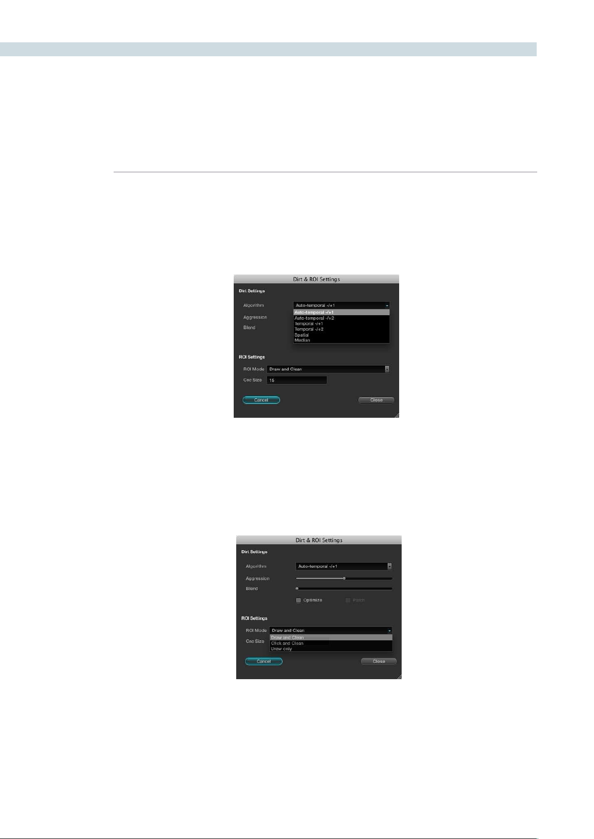
COLOR 176
Interactive Dirt & Dust Removal Tool
DaVinci Resolve provides an interactive Dirt and Dust Removal tool which may be accessed from either
the Viewer or Color screens by clicking on the Dirt Removal Tool icon, located at the left of the Viewer
display. A right mouse click on the button will open the setup window.
Within the Dirt Settings section you can adjust the Algorithm section to select the filtration being used
for the correction and also the Aggression and Blend sliders depending on the degree of correction to
be applied. The ROI Settings allows you to select the correction method. If you choose the Click and
Clean mode, this will apply the correction once you click on the object. If you select the Draw and Clean
mode, you can highlight the dirty area with the mouse and then the correction will be applied. If you are
unhappy with your correction select, undo to return to the original image.
Dirt and dust set up widget
Dirt and dust set up widget
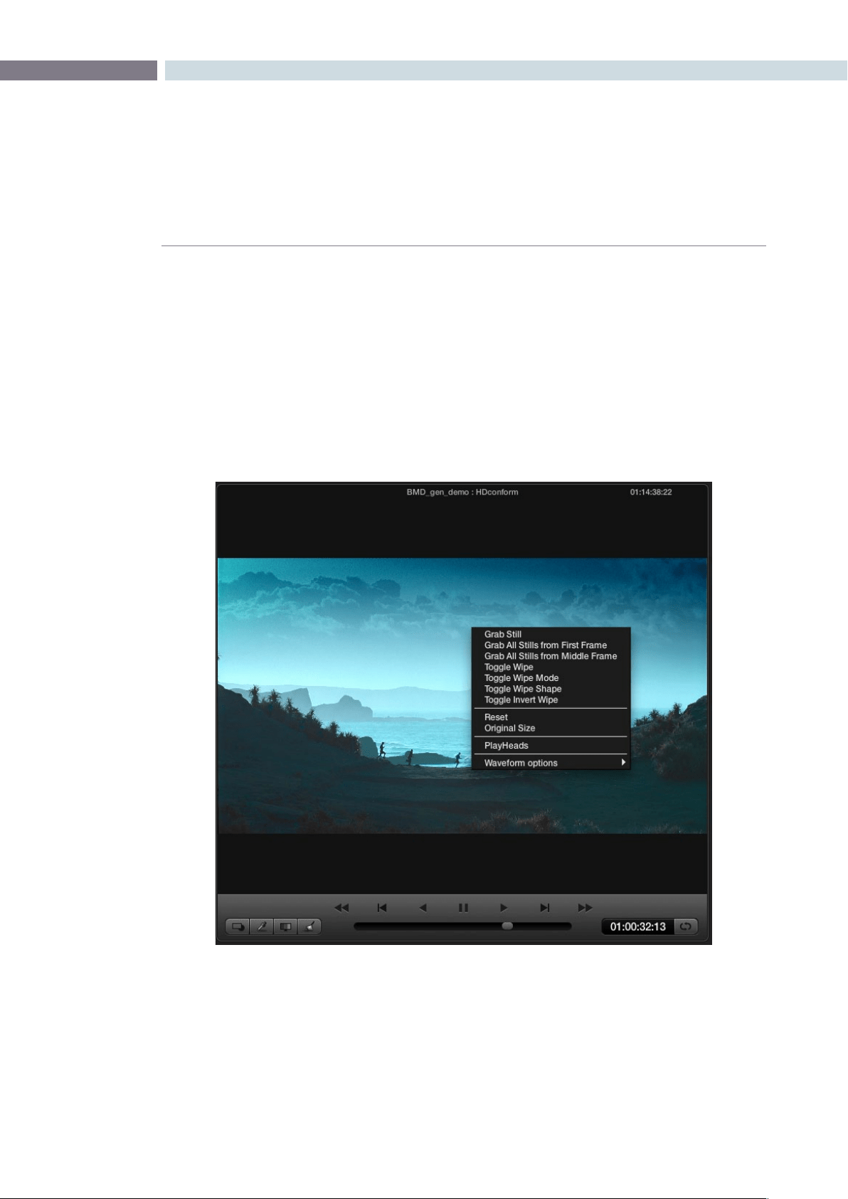
CHAPTER
COLOR
COLOR177
9
Viewer Window Options
There are a number of center and right click mouse options for the viewer.
YoumayZoomInandOutoftheimagewithintheViewerbyusingarotarycontrolwithinthecenter
mousebutton.YoumayalsoZoomInandOutoftheimagewithintheViewerdisplaybyusingthe+
and – keys on the computer keyboard. If you hold down the center mouse button and drag the mouse,
it will move the image position within the Viewer display. To reset the Viewer display to the original size
andposition,rightmouseclickwithintheViewerwindowandselect‘Reset’fromthemenuthatappears.
A right-click on the mouse while it’s over the Viewer will pop-up an options window.
Color screen right-click options
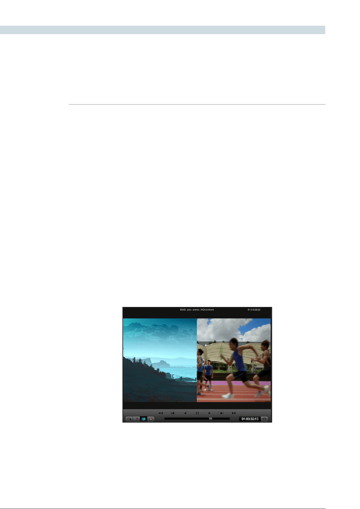
COLOR 178
Viewer Stills Display
Therstfewofthepop-upoptionsrelatestostills.‘GrabStill’willsimplygrabthecurrentframetomake
a still and place it in the Gallery Stills display. This still can then be used as a reference for comparison in
otherscenes.‘Graballstillsfromrstframe’willgrabastillfromeverycliponthetimelineusingtherst
frame of each clip.
‘GraballstillsfromMiddleFrame’willperformthesamefunctionexceptusethemiddleframeofeach
clip as the source of the still. Once this procedure has started, it will continue until completed, which
could take some time.
The‘ToggleWipe’selectionwillturnthewipeonandoff.ThisfunctionontheDaVinciResolvecontrol
surfaceiscalled‘PlayStill.’TheToggleWipemodewillselecttocomparethecurrenttimelinecliptoeither
the Gallery Still, the matching Offline frame or another clip on the timeline. To use, select a clip on the
timeline, toggle the mode to Timeline and then use the mouse to select the thumbnail of the reference
clip.Rightclickonthethumbnailtoselect‘WipeTimeline’andthereferenceclipwillbehighlightedin
yellow when you move to the clip to compare.
Alternatively,tocomparethecurrentcliptotheOfine,selectthe‘Still/Timeline’buttonontheDaVinci
Resolve control surface until the Offline label is seen on the status display. (More on the Status display
later in this chapter.) You will then be able to perform a wipe with the offline recording in conjunction
with the clip.
The Toggle Wipe Shape option switches between Vertical Wipe, Horizontal Wipe, Mix, or a Key or Alpha
control. (More on this later when we look at green screen keying and display.) Toggle Invert Wipe will
swap the reference and current images in the Wipe display so you can see the other side of the images.
The Reset option will set the image to the normal display for the viewer. The original setting will display
the image pixel for pixel so it is usually used for getting quick zooms to the source image size to look for
imperfections in the original image.
Wipe between the current clip and the still
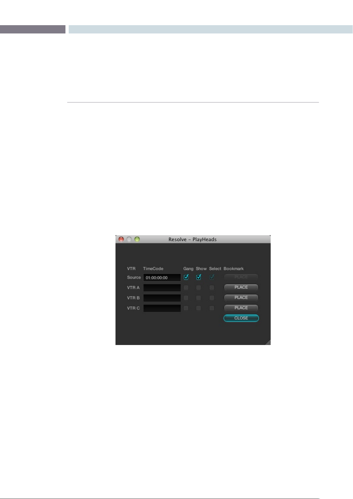
CHAPTER
COLOR
COLOR179
9
The PlayHeads Viewer mode is commonly used to compare a reference clip with up to three additional
clips, by placing a total of four playheads in the timeline. Multiple playheads are useful for many things,
for example, comparing clips from the same angle of coverage that you’re trying to balance evenly with
one another. Alternately, you could use them to simultaneously view a variety of shots in the timeline
with which to preview different looks.
PlayHeads can be configured using the PlayHeads window in the GUI, or by pressing the MODES button
of your DaVinci Resolve Control Surface, and pressing the PLAY HEADS display button to access this
functionality and which will be covered later in this section.
Creating a Stereoscopic Project
Using the GUI and your mouse, playheads can be enabled and configured using the PlayHeads window.
To open the PlayHeads window:
Right-click the Viewer, and choose PlayHeads from the shortcut menu.
Once the PlayHeads window appears, you can use its checkboxes and buttons to choose which
playhead is attached to which clip in the timeline.
To assign a new playhead to a clip using the PlayHeads window:
1. Click a thumbnail in the timeline to place the initial “Source” playhead, or leave this set
to the current clip.
2. Choose a VTR (A, B, or C) that you want to use to place the next playhead by clicking
its Place button. It’s best to choose the next one down on the list.
The PlayHeads window
PlayHeads
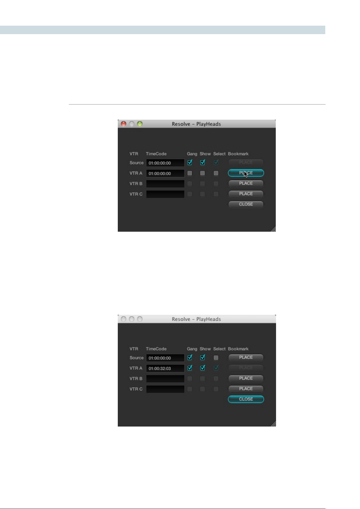
COLOR 180
The Gang and Show checkboxes of VTR B are now enabled.
3. Turn on its Gang checkbox to display that playhead in the Viewer.
The accompanying Show checkbox automatically turns on, and a second frame
appears side by side next to the first one in the Viewer.
4. To select which clip appears in this new frame, turn on the Select checkbox of the VTR
you just ganged, and then click a different thumbnail in the Timeline.
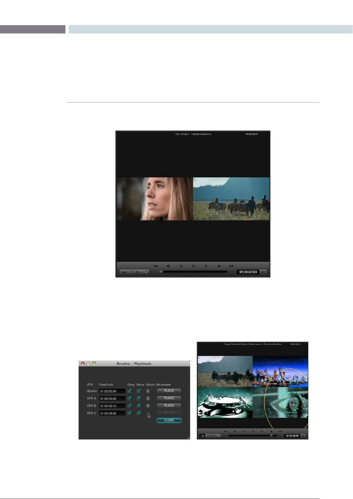
CHAPTER
COLOR
COLOR181
9
At this point, you’ve set up a side by side view comparing two different clips.
You can choose to display up to four different frames in the Viewer, using the Source and VTR A, B,
and C controls in the PlayHeads window. The Viewer will show a two-up, three-up, or four-up view
as necessary to accommodate the extra PlayHeads you enable, all of which will be output to your
client display.
Color screen viewer with four playheads active

COLOR 182
Once you’ve configured the PlayHeads window, the following controls let you reconfigure the available
playheads:
Gang checkbox: Lets you choose which playheads will play during playback. If a
VTR’s checkbox is turned off, that playhead will only display a
still image.
Show checkbox: Lets you turn playheads on and off in the Viewer.
Select checkbox Turning on a VTR’s select checkbox lets you move that playhead to
another clip by clicking a thumbnail in the thumbnail timeline. This
also determines which clip is currently selected for correction.
Place checkbox: Lets you assign a previously unassigned playhead.
It’s important to understand that, once multiple playheads have been placed in the Timeline, the
currently selected playhead (the VTR with the Select checkbox turned on) determines which clip is
currently selected for correction.
Once multiple playheads have been configured, you can disable this functionality by turning off the
Show checkboxes for VTR A, B, and C.
PlayHeads Via the DaVinci Resolve Control Panel
On the DaVinci Resolve control surface, playhead and VTR linking is done using the PlayHeads mode,
whichexposescontrolsonthecenterpanel.AdditionalplayheadbuttonscanbefoundontheJog/
Shuttlepanel,abovetheJog/Shuttlewheelitself.
To open the PlayHeads mode of the DaVinci Resolve control surface:
1. Press the Modes button on the center panel.
The display buttons directly underneath the rotary knobs update to show the available
mode options.
2. Press the PLAY HEADS display button on the center panel.
The display buttons update to show the various playhead controls.
Once you’ve entered playheads mode on your control panel, you can assign playheads using the
following procedures.
To enable one of the three playheads in addition to the source, then display them in the Viewer:
1. Press GANG ON/OFF.
2. Do one of the following:
•PressPLACEA(orB,orC)toenablethatplayhead.
•OntheJog/Shuttlepanel,pressSHIFTUPandthenPLACE(A),PLACE(B),or
PLACE (C).
If you have the PlayHeads window open in the GUI, you can see the corresponding VTR (playhead)
checkboxes becoming enabled with each PLACE button you press. By default, they remain off.

CHAPTER
COLOR
COLOR183
9
3. Press GANG SRC, GANG A, GANG B, or GANG C to display that playhead in the Viewer.
Pressing the same button again hides that playhead in the Viewer.
As with the PLACE buttons, the GANG buttons correspond to controls within the
PlayHeads window of the GUI. As you press the PLACE buttons, you can see the Gang
and Show checkboxes turn on and off.
Once multiple playheads are placed in the Timeline, It’s also possible to switch among clips with
playheadsusingtheSRC(L),A(R),B,andCbuttonsoftheDaVinciResolvecontrolsurface’sJog/
Shuttle panel.
To switch which playhead is the currently selected shot:
1.PresstheSRC(L),A(R),B,orCbuttonsontheJog/Shuttlepaneltoswitchthecurrent
shot to that playhead.
2. Use the transport controls, or press PREV SCENE or NEXT SCENE to switch the shot
at the new current playhead.
The currently selected playhead which clip is currently selected for correction. This is the same as
clicking the Select button in the PlayHeads window of the GUI.
To switch between viewing multiple playheads, and a single playhead:
Press the GANG/SOLO display button on the center panel.
If you have the PlayHeads window open in the GUI, you can see every Show checkbox except for the
one corresponding to the currently viewed playhead turn off. Pressing GANG/SOLO again would turn
them back on.
If you’re finished altering the playhead settings, you can exit playhead mode.
To exit playheads mode on the DaVinci Resolve Control Surface:
Press the EXIT display button on the center panel.
Exiting playhead mode doesn’t disable multiple playhead display in the Viewer, it simply puts the control
surface’s center panel back to the default button and knob mapping.

COLOR 184
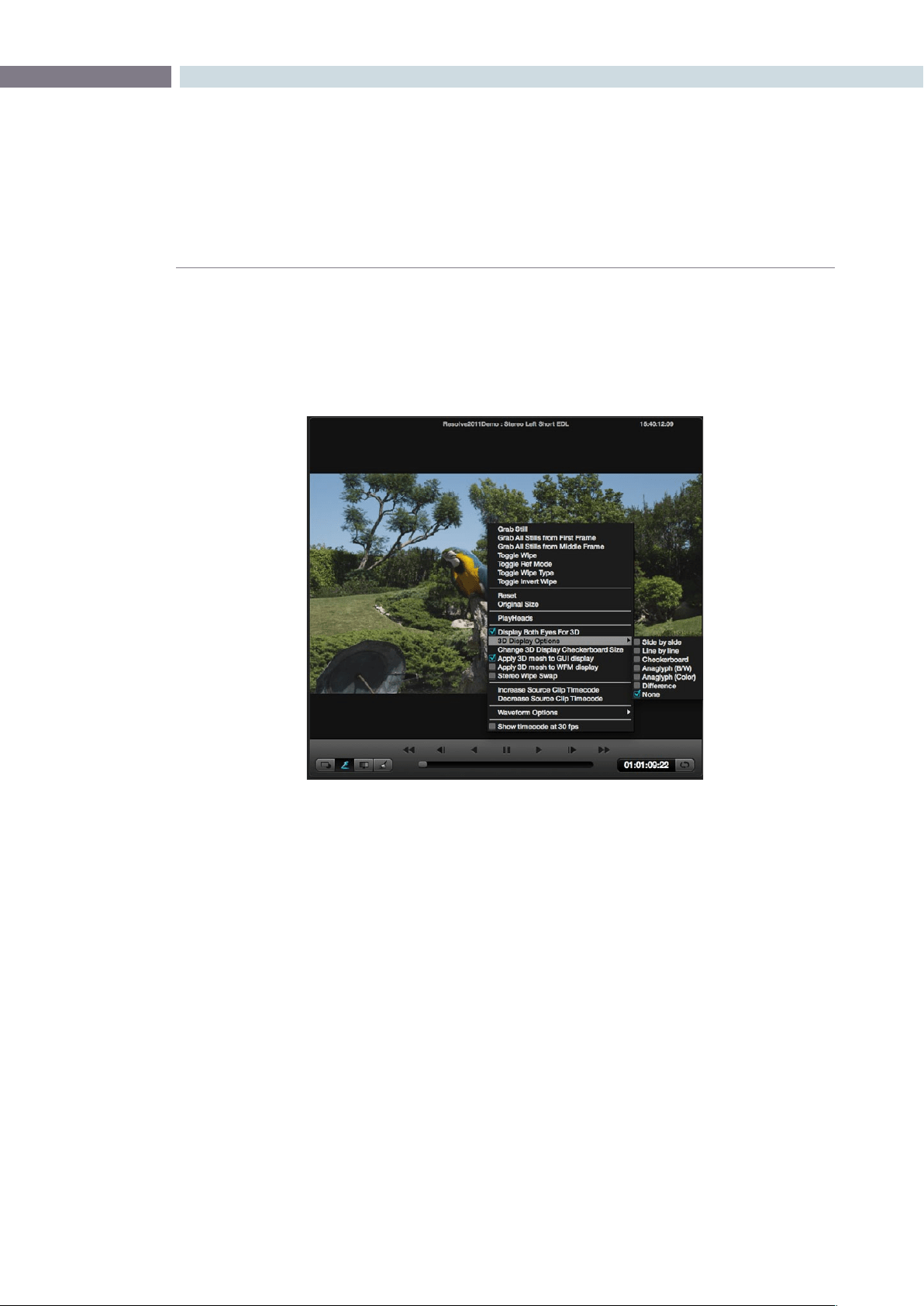
CHAPTER
COLOR
COLOR185
9
3D Display Modes
For Stereoscopic 3D projects, set the selection “Display Both Eyes for 3D” to see both eyes on the SDI
output. The format of the display can be selected from the various display types. Side-by-side, Line-by-
Line, Checkerboard Anaglyph B&W or Anaglyph Color, Difference or none.
To see these selections on the viewer and WFM check the option to apply the mesh display.
Stereoscopic3Dimagesareoftenproducedoutofsyncandthe‘IncreaseandDecreaseSourceClip
Timecode’ selections move the active clip one frame at a time to permit visual resyncing.
Color screen viewer with four playheads active
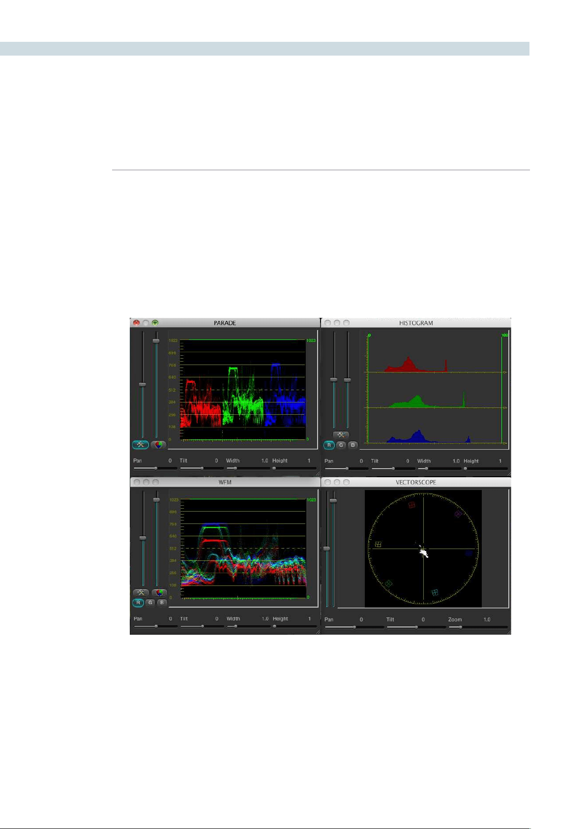
COLOR 186
Waveform displays
DaVinci Resolve offers a number of built in waveform displays, all of which work at the native resolution
of the system rather than at the video standard selected for clip playout. This means you can see the
full data range of the source image with the correction applied, regardless of which video standard you
wish to master.
The displays Waveform, Parade, Vectorscope and Histogram allow you to monitor the levels of the
correction that are being applied to the image. Within each display, there are the controls that allow you
to vary the brightness of the scale and information displayed.
Show Timecode at 30 fps
The final item on the list of options is a checkbox to show the timecode in the timecode display at 30 fps.
This is used to show timecode as it would appear on tape in a 2:3 pull up mode from a 24 fps project.
Waveform Display
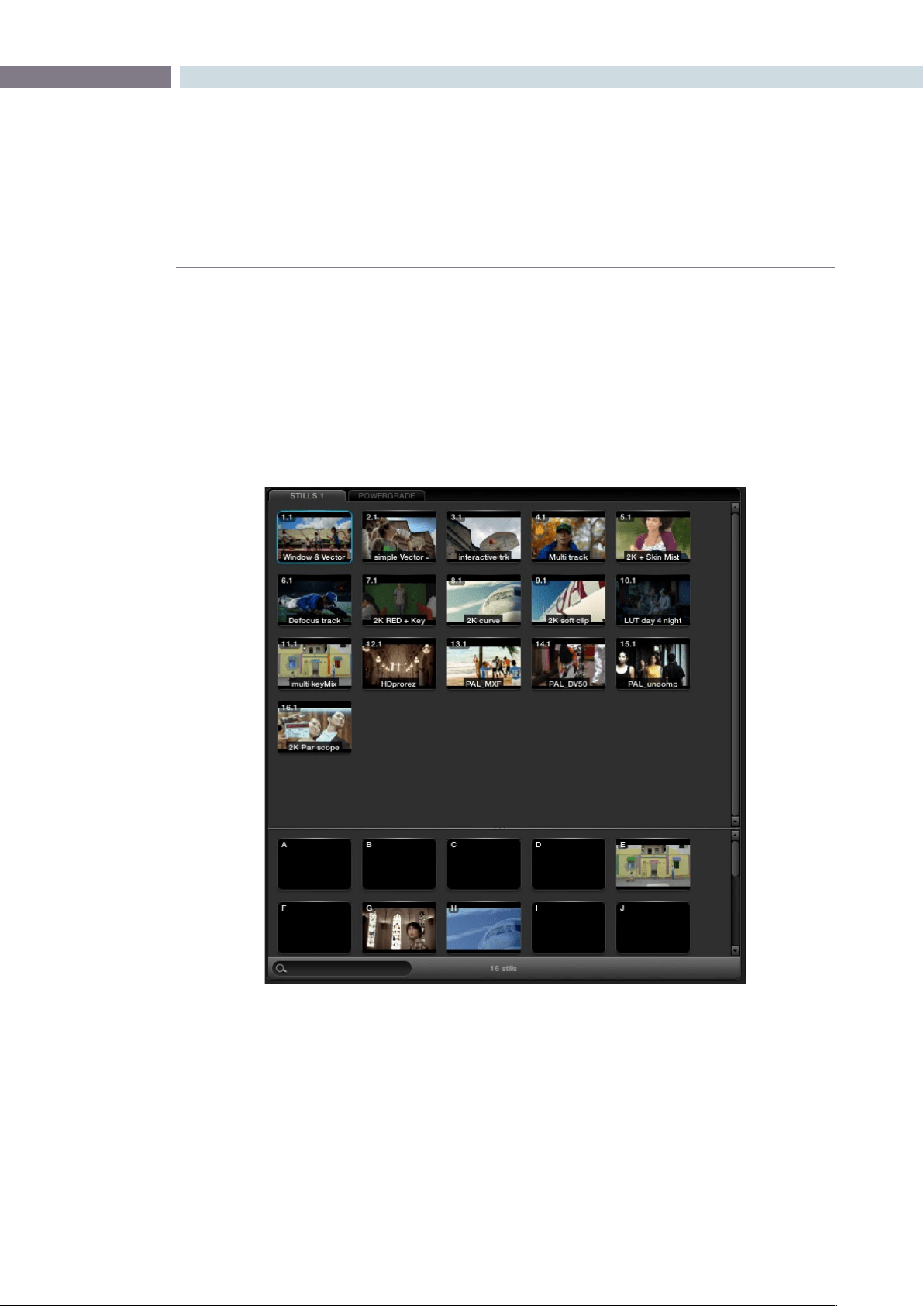
CHAPTER
COLOR
COLOR187
9
In the center top of the Color screen are the Stills, PowerGrade and Memories tabs. While all of these are
managed on the Gallery screen, they are displayed on the Color screen for quick selection and are used
for color matching during the grading session.
As described in the Viewer section, you may compare the stored images to those being graded by
using a Wipe or Mix. This provides a simple and fast method of matching grades between scenes.
There can be multiple Stills and PowerGrade tabs. The Memories are shown in the lower section of
this window.
Stills, PowerGrade and Memories
Stills, PowerGrade and Memories
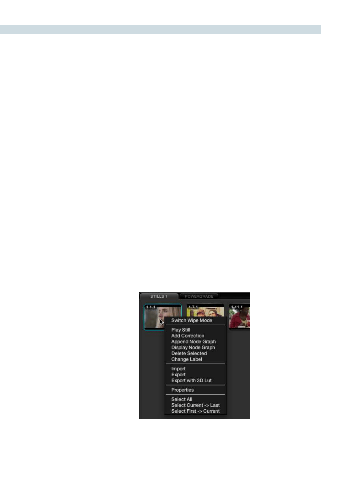
COLOR 188
Whenyoupressthe‘GrabStill’buttonontheDaVinciResolvecontrolpanel,orright-click’GrabStill’on
the Viewer, you’re capturing a high resolution still image of the frame currently displayed on the timeline
and at the same time capturing the grading metadata information relating to that grade. This means the
still can be used for both visual reference and also for direct grade Copy and Paste operations.
Note: All stills are saved internally as DPX image files.
Saved still frames (stills) are added to the current Still tab on the Color screen which is mirrored on
the Gallery page. You can Delete stills by right-clicking a still and choosing “Delete Selected” from the
contextual menu. One or more stills can be deleted at once. Right click and use the ’Select Current ->
Last’ or ’First -> Current’ selection, or hold the Shift key while selecting multiple stills for an operation to
impact more that one still at a time.
Stills display an identification number in the upper left corner, that consists of three numbers separated
by periods:
The first number is the video track it’s saved from.
The second number is the number of the clip the still is from.
The third number is incremented every time you save another still from that same clip.
For example, the third still that’s saved from clip 4 in track V1 is numbered 1.4.3.
Multiple stills for a clip are displayed adjacent to one another for quick reference.
Stills
Individual Still Right Click Options
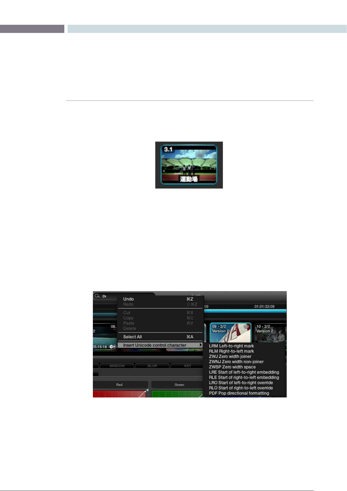
CHAPTER
COLOR
COLOR189
9
Stills can be named/renamed by placing the cursor over the still, right clicking, and choosing the pull
downoption‘ChangeLabel’.IfyoursystemhasUnicodelanguageoptionsloadedyoucanaddnames
in different languages.
Comparing Stills in the Viewer
Selecting‘PlayStill’viarightclickonthestill,oronthecontrolpanelwilldisplaythestillontheViewer
with a wipe to the current scene/frame. The Wipe mode can be a Horizontal or Vertical Wipe, or a Mix;
these options are select from the panel directly or via the mouse on the Viewer using the right-click
pull-down‘SwitchWipeMode.’Ifyoudoubleclickonastoredimage,theViewerwillautomaticallyenter
into Wipe mode and you may adjust the wipe by using the fader bar. You can also place your mouse
over the wipe on the Viewer and click and drag to move the wipe position.
Japaneseisoneofthemany
languages supported
Unicode Name Controls

COLOR 190
Copying Grades From Stills
When you save a still or memory from a clip using the Grab Still command, DaVinci Resolve also saves
thatclip’saccompanyinggrade.The‘AddCorrection’commandappliestheentiregradeincluding
eachnodeofadjustment,thePTZRand3Dsettings,andtheSourcemetadatasettingsforR3DorArri
Alexamediafromastilltothecurrentclip.Theclip’spreviousgrade,PTZR,3D,andSourcesettingsare
overwritten. This makes it easy to copy grades and settings from other shots in a program, or to store
grades and settings for future use.
Note:EachversioncanhaveindividualPTZRand3Dsettings,butallversionsbelongingtoaparticular
clip share common Source settings.
Preserving Nodes and Parameters When Copying Grades
A group of settings, within the contextual menu of the Still Store and Powergrade tabs are available
to prevent you from accidentally overwriting clip settings or nodes that you want to preserve when
copying grades to the current clip.
There are two cases where this is particularly valuable:
ThePTZR,3D,andSourcesettingscanallbeoverwrittenwhenapplyingasavedgrade.
Many colorists grade in a very structured manner, using the first one or two nodes as the underlying
grade with which to optimize each clip and balance it with the rest of the scene. By default, applying
a grade overwrites all nodes, losing such initial adjustments.
To preserve clip settings when copying grades:
Right-click anywhere within a Still or PowerGrade tab, except on a thumbnail, and choose one of
the following options:
Copy Grade: Preserve Number of Nodes:
Lets you choose 0, 1, or 2 nodes to be protected when applying a
grade. When set to 1 or 2, that number of nodes from the copied
correction will be ignored when applying a grade to a clip that
already has the same number of nodes. For example, if you set
this to 2, but the clip you’re copying to only has one node, only
the first node will be ignored from the copied grade.
Copy Grade: Preserve Stereo Adjustments:
When enabled, every node of a saved or copied grade is applied,
but the stereo adjustments of the current clip are preserved.
Copy Grade: Preserve Source Settings:
When enabled, every node of a saved or copied grade is applied,
but the Source settings of the current clip are preserved.
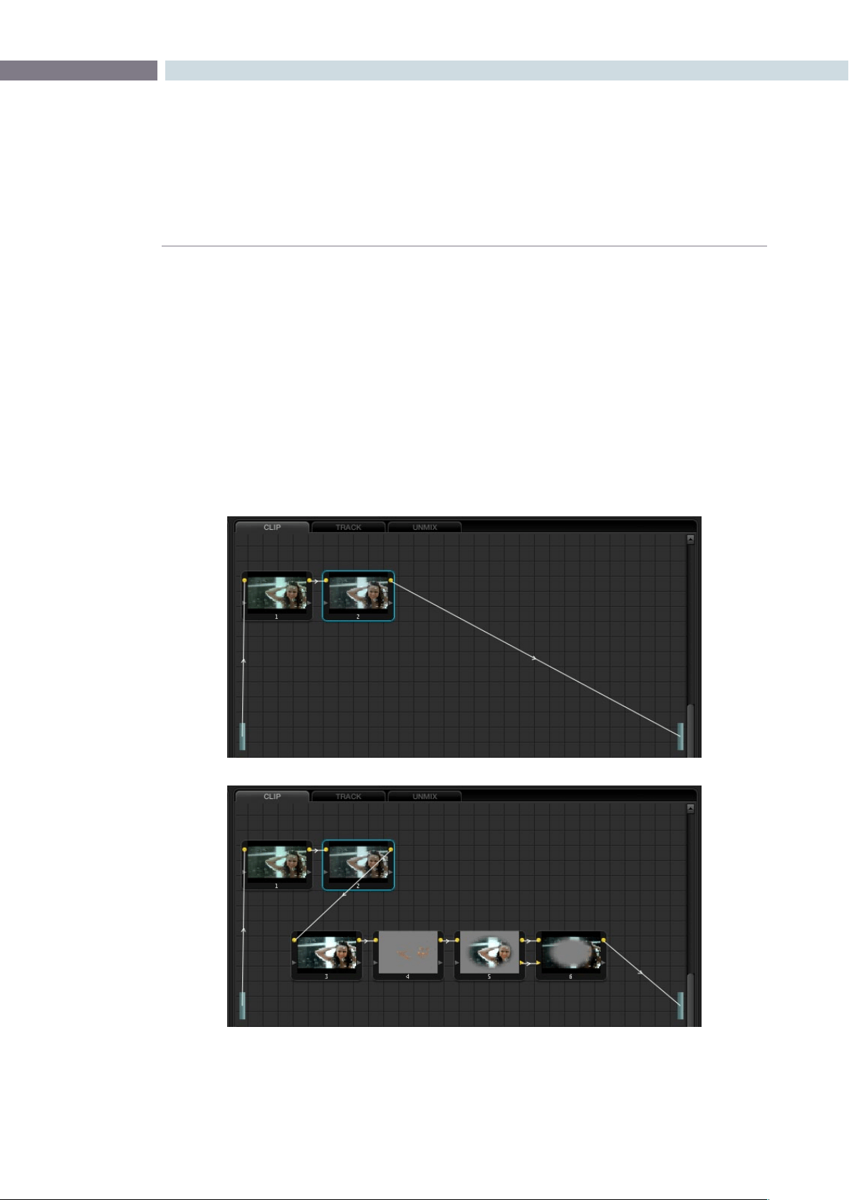
CHAPTER
COLOR
COLOR191
9
Append Grade
When right-clicking on a still in the Stills or Powergrade tabs, you can also choose “Append Node
Graph.” This adds the entire node graph of the saved still to the end of the node tree of the current clip.
In other words, the current clip’s grade isn’t overwritten, the applied grade is added to it.
If you plan ahead, saving fragmentary grades that create specific effects or adjustments within a few
nodes, this is a great way of creating a grading toolkit that you can use to mix and match different
specific adjustments or effects that you’d like to add to other grades that you’re creating.
For example, you could create a two-node glow effect, save it, and then apply that effect at the end of
a completely different clip’s grade.
A clip’s node graph before appending a grade, and after appending a grade
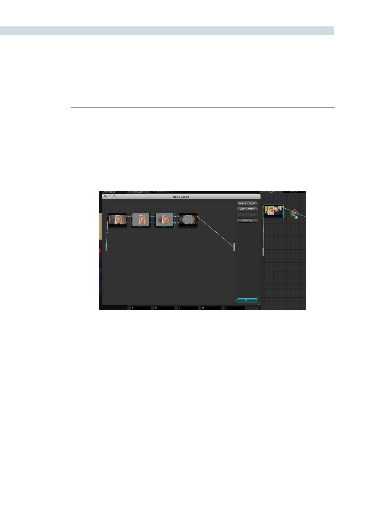
COLOR 192
Copying Individual Nodes From Stills
If you want to use specific nodes or adjustments from a particular saved still, you can also use the
‘DisplayNodeGraph’commandtoopenanystill’snodegraphandthencopyeitherallofthegraph,or
any one node.
Justselectthenodewithyourmouse,clickanddragittotheNodeGraphdisplayontherightofthe
main screen, and place it where you would like the correction applied in the image correction path.
Alternatively,youcanselectjustthecolorparametersorjustthePTZRparametersfromthestill,orfrom
thiswindow,youcanselectall.‘Exit’toclosethewindowwhenyouhavenished.
Dragging a node from a displayed node graph onto the node tree of another clip
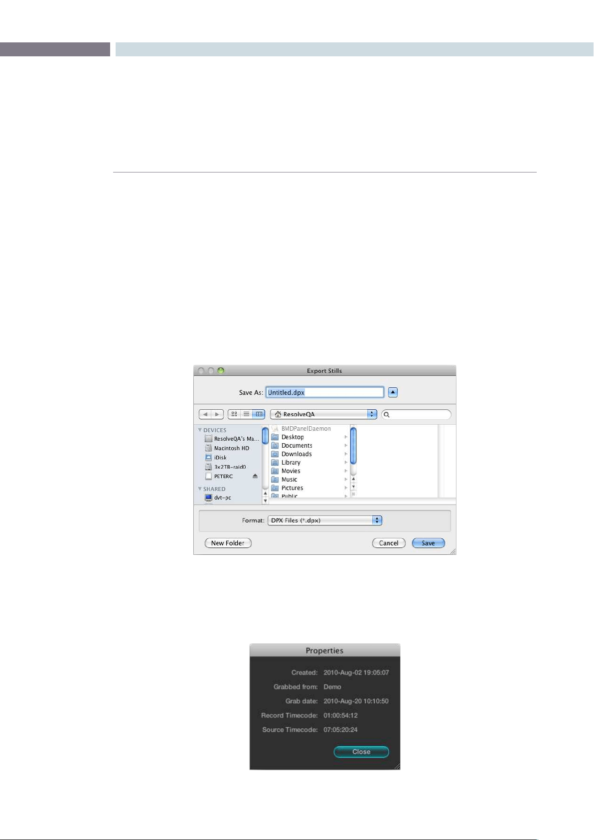
CHAPTER
COLOR
COLOR193
9
Export and Import Stills with DaVinci Resolve eXchange (DRX)
color correction metadata
To export images simply select the still and right click for Export or Export with Display LUT option.
The Display LUT used in this case is the one selected on the Configuration page. All stills exported also
have an associated DRX file saved in the same folder which contains the color correction and node
graph metadata. The still and DRX file can be copied to another DaVinci Resolve and when the still in
imported, the grading metadata will be read and stored with the still in the Gallery for use in any grading
session. If when importing stills from other systems and applications Resolve does not locate the DRX
metadata file the still will be imported to use as a visual reference but no color correction metadata will
be associated with the still.
The supported file formats for importing and exporting stills are: dpx, cin, tiff, jpeg, png, ppm, bmp and cpm.
Sorting Stills
These parameters are used by DaVinci Resolve for sorting the stills using the options that are selectable
with a right mouse click.
Stills Properties
Export Still Pop-up window with file options displayed
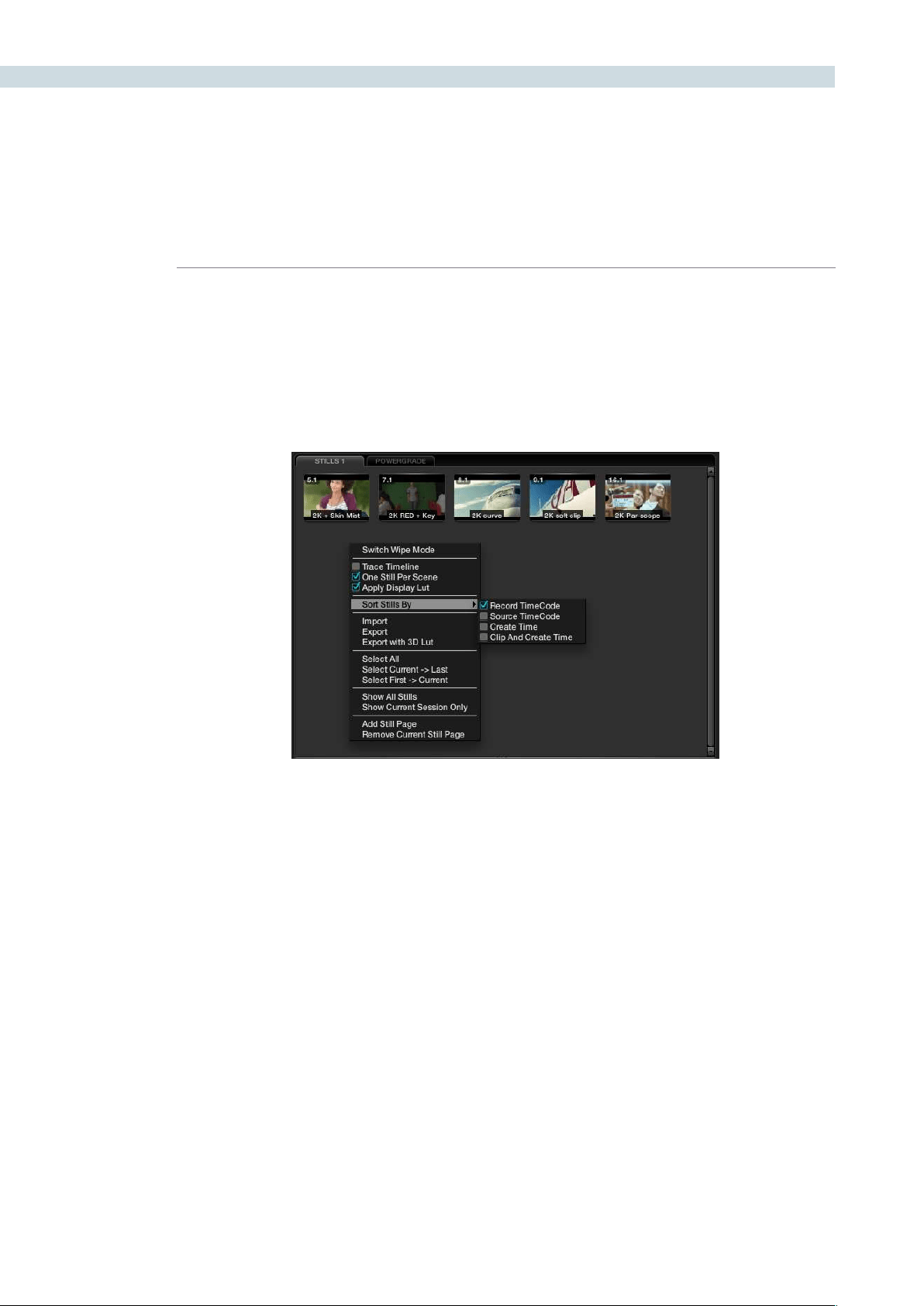
COLOR 194
When stills are added to the Still tab they are placed next to other stills from the same scene and
generally in record timecode order. You can also select the stills to be sorted and displayed in the
order of the source timecode or the creation date and time, or by the clip order with the creation date
and time.
If you have multiple sessions in your project you can also select to display stills from just this Session or
stills from all Sessions.
Other Still Options
Images can be stored in multiple Still pages to make it easier to find or switch between stills. These
pages are configurable and while the Gallery screen offers the full suite of still management tools, on the
Color screen you can add or remove a Stills tab.
JustclickanddragastilltotheMemoriessection,ifyouusethisstilloften.Thiswillgiveyouaonekey
selection for even faster operation.
Youwillnotethatthereisanoptionto‘TraceTimeline.’Withthisselected,thestillthat’shighlightedwill
always match the scene selected on the main timeline.
The‘OneStillperScene’selectionwillforceasinglestilltobesavedforeachclip.Anyclipswithmultiple
stills will retain those stills until you capture another for that clip.
Searching For Stills
You can search for stills within the selected tab by using the Search window at the bottom left of
the Stills display. Simply place your cursor in the Search window and click, then type the name or
description you are searching for and DaVinci Resolve will automatically show the results in the tab
above. Note there is also a still count, which will show how many stills are in this tab, or how many are
shown based on the search.
Stills Right Click Options
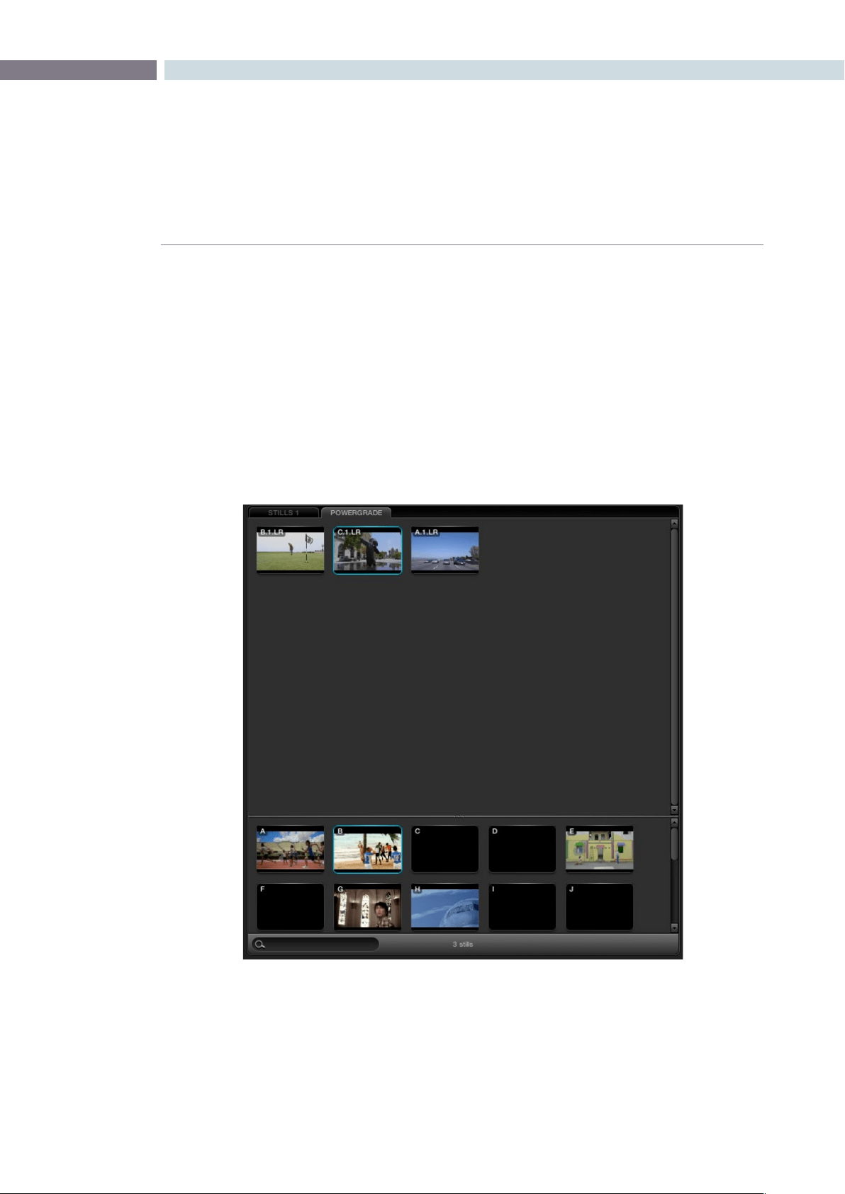
CHAPTER
COLOR
COLOR195
9
The PowerGrade tab shows stills that are always available and referenced to the User Name no matter
which Project you have open. Normally stills relate to Sessions within a particular project. You can always
copy stills from other Users and other Projects, but this is a manual process and there are times when
you may just want to have specific stills, with their Node Graphs, that are always available to you no
matter which project you have open.
The PowerGrade stills are the same as all others in most respects. The ability to see these stills when
you open another Project provides a simple way to copy grading information between Projects. As the
Node Graph is saved with the PowerGrade still, complex multilayer grades with LUTs can be saved and
recalled with ease.
Thisalsomakesthemidealforspecic‘looks’thatacoloristmakesforlateruse.Youcandragstillsinto
the PowerGrade tab from your Memories, or save directly to the tab.
PowerGrade
PowerGrade
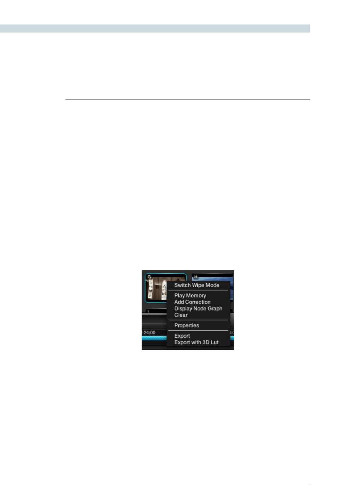
COLOR 196
Within DaVinci Resolve, every scene has a grade that is stored in an active Memory. Colorists consistently
refer to this current Memory and compare it to the stills to match grades. You can always clear this
Memory to get to a default Memory by using the Base Mem control. Comparison of the current Memory
andMemoriesthatareusedveryoften,iseasilydoneusingtheAtoZMemories,whichyouwillndat
the bottom of the Still section. These stills are in most respects the same as the others in the Stills or
PowerGrade tab with the exception that you can save and recall the stills from the control panel with
great speed.
OntheDaVinciResolvecontrolsurface,simplyselect‘Current’andthenoneoftheAtoZMemorykeys
tosavethecurrentscenesgradetothatMemory.The‘Current’andAtoZkeysareonthefaderand
also the Transport panel. In each case, the Memory is seen in the Memory display with a small letter that
identifies to which Memory it was saved. To recall a grade from the Memory, simply select that Memory
with a one button selection.
A key feature for the stills is the capture and display of the Node Graph which will show you how the
grades were constructed. This also applies to the Memories. Right mouse click on an image within the
Stillsdisplay,andthe‘DisplayNodeGraph’optiontodisplaytheNodeGraph.Varioussectionsofthe
correction can be copied to the current correction by dragging the appropriate nodes to the current
NodeGraphdisplay,orselectthe‘ApplyCorrection’buttontocopytheentirecorrectionintothecurrent
clip. The Still Nodes may be dragged on top of an existing node to replace that node’s enhancement or
a node can be dragged and inserted independently into the Node Graph line.
Memories
Memory Right Click Options
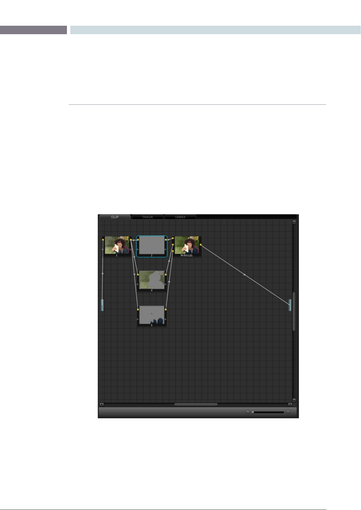
CHAPTER
COLOR
COLOR197
9
Whenever a color correction or enhancement is performed on DaVinci Resolve, it must be carried
out within a node. The Node Graph, found in the upper right of the Color screen, provides a visual
representation of the image processing path and node/layer priority for every correction for each clip.
The Viewer display and the grading monitor present the output from this Node Graph. There are three
tabs in this window: Clip, Track, and Unmix.
Functionally, the Node Graph works the same for each tab, however, each shows a different perspective
of Resolves image processing. Detail of this will be covered later in the Dynamics Timeline section of this
chapter. On the left and right hand side of the Node Graph is a blue rectangle. Consider these points
the Input and Output, respectively. By default, DaVinci Resolve draws the Node Graph with a single
‘Correction’nodefromtheProcessingInputboxandthenodesoutputconnectedtotheProcessing
Output box.
Node Graph
Node Graph
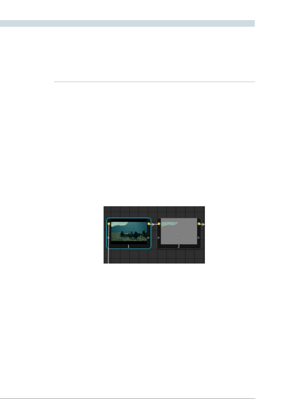
COLOR 198
The nodes have a yellow dot for the image Input and Output hooks, and a yellow triangle for the Key
or Matte Input and Output hooks. It is important that the connecting line from the processing input on
the left through the various nodes via the image hooks, is connected to the output on the right. If the
connection path is not complete the nodes will not display images, but instead will show an icon and
the correction will not be visible on the Viewer or Grading monitor.
With the path complete, the image shown in each node within the graph will give you a visual indication
of the correction that is taking place within that node. The Node Graph display may be zoomed by using
the rotary center mouse button, and moved by dragging the mouse while holding down the center
mouse button.
Managing Nodes
Ambitious grades may require trees of multiple nodes to create the necessary effect. This section covers
the mechanics of putting nodes together into the structures that are described in more detail later in
this chapter.
You can only select one node at a time. When you adjust any of the parameters or settings in the Color
page, you’re adjusting the current node, which is highlighted with a blue border.
To select a node, making it the current node, do one of the following:
•Double-clickanynodeinthenodegraph.
•UsingtheDaVinciResolvecontrolsurface,pressthePreviousNodeorNextNode
buttons(foundontheJog/ShuttlepanelunderneaththeShuttlecontrol)
•UsingtheDaVinciResolvecontrolsurface,enterthenumberofthenodeyouwant
to select using the keypad, and then press the SELECT NODE button (all on the
Jog/Shuttlepanel).
The following procedures describe all of the ways you can add nodes to the node graph as you build
each grade’s node tree.
The currently selected node has a blue border.

CHAPTER
COLOR
COLOR199
9
Basic methods of adding nodes to the tree:
To add a serial node after the currently selected node:
Press the S key, choose Nodes > Add Serial from the menu, or
press the ADD SERIAL button on the T-bar panel of the DaVinci
Resolve control surface.
To add a node in parallel to the currently selected node:
Press the P key, choose Nodes > Add Parallel from the menu,
or press the ADD PARALLEL button on the T-bar panel of the
DaVinci Resolve control surface.
To add a serial node to the very end of the node tree:
Press Shift-A, choose Nodes > Append Node from the menu,
or press the APPEND NODE button on the T-bar panel of the
DaVinci Resolve control surface.
To add a serial node before the currently selected node:
Press Control-Shift-S, or choose Nodes > Add Before Current, or
press SHIFT DOWN and then ADD SERIAL on the T-bar panel of
the DaVinci Resolve control surface.
To add a disconnected node to the node graph:
Right-click anywhere within the node graph’s background,
and choose Add Node > Corrector from the contextual menu.
Disconnected nodes have no effect on a node tree until
they’re connected.
There is no limit to the number of nodes you can create and connect to one another, and you can make
as many or as few parameter adjustments as you like within each node.
In addition to these basic methods of creating nodes, there are also dedicated commands (available
from the keyboard, menu, or control surface) for adding serial nodes with Circular/Linear/Polygon/
Curve windows automatically turned on to their default settings
Basic methods of adding nodes to the tree:
To add a serial node after the currently selected node:
•Node+CPW(CircularPowerWindow,Shift-C)
•Node+LPW(LinearPowerWindow,Shift-Q)
•Node+PPW(PolygonalPowerWindow,ShiftG)
•Node+PCW(PowerCurveWindow,ShiftB)
To delete a node, do one of the following:
•Selectanode,thenpresstheForward-Deletekey.
•Right-clickanode,andchooseDeleteNode.
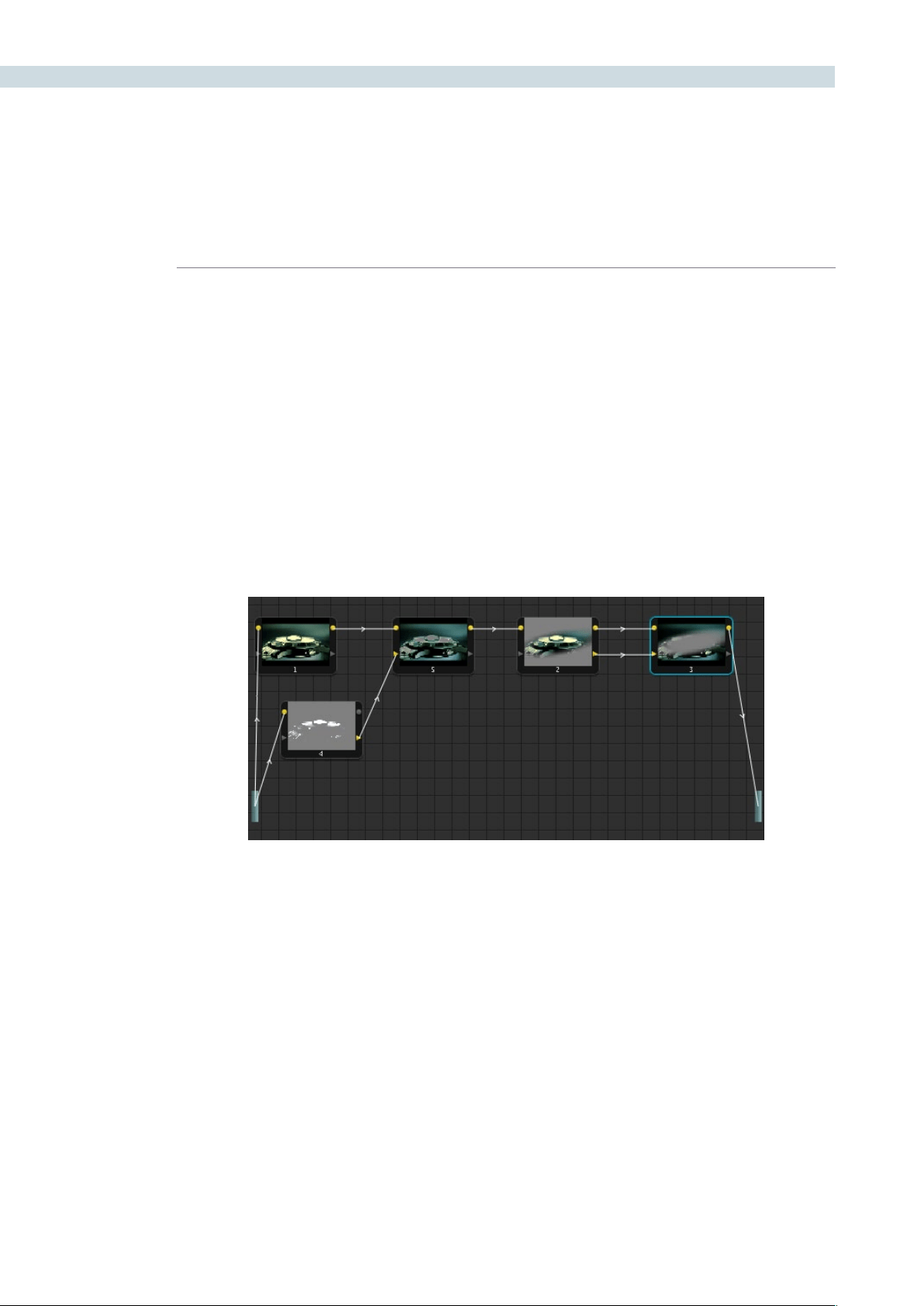
COLOR 200
•UsingtheDaVinciResolvecontrolsurface,selectanynode,andpresstheDEL-
CURRENT button (on the T-bar panel).
After you’ve deleted a node, the node to the left and right of the node you deleted are automatically
connected together so that the node tree is unbroken.
Manually Connecting Corrector Nodes
Every serial and parallel node you add is a “Corrector” node, which is capable of either primary or
secondary correction, depending on whether or not you enable the Qualifier/Window/Matte controls.
As a result, each Corrector node has two inputs and two outputs, which lets you separately manage the
RGB image channel, and the Key channel (Alpha or Matte). Here’s an explanation of the components of
a basic node tree, and how they fit together.
The Source:
ThesourceistheclipasprocessedbythePTZRandSourcedecodesettings,
ungraded. It’s represented by the blue bar to the center left of the node graph. The
Source bar outputs RGB data, and is connected to the RGB input of the first node
in your tree. You can connect the Source bar to more then one corrector node,
creating multiple simultaneous streams of image processing that you can eventually
recombine in different ways using the Parallel or Layer mixer nodes.
RGB Inputs and Outputs:
The yellow dots at the upper right and left of each node are used to connect the
RGB image output from one node to the RGB input of the next node. For a corrector
node to have an effect, you must connect both its RGB Input and its RGB output to
neighboring nodes in the tree.
An example node tree with both image and matte processing. The RGB Outputs and inputs of nodes 1, 5, 2, and 3
are connected in serial. Node 4 is feeding a Key into node 5, and node 3 is an Outside node with both its Key and
RGB inputs connected to the node before it.

CHAPTER
COLOR
COLOR201
9
Key Inputs and Outputs:
The gray triangles at the bottom right and left of each node are used to route the
key channel generated by a node’s Qualifier or Window controls, or imported via a
Matte clip that you previously associated with a clip in the Browse page. When you
connect the Key output of one node to the Key input of another, you basically copy
the first node’s key to the second node. You can also combine the Key outputs of
multiple nodes in various ways using the Key Mixer node.
The Output:
The RGB output of the last node in a tree must be connected to the Output bar,
which “completes the circuit” of image processing, and passes that correction on to
the next stage in the DaVinci Resolve image processing pipeline. If the output is not
connected, the node tree has no effect on the clip. You can only connect one RGB
output at a time to the Output bar.
Nodes are connected to one another by “connection lines,” with a small arrow bisecting each line that
indicates the direction in which image or key data is flowing.
To connect two disconnected nodes:
•Click-and-dragfromtheRGBorKeyoutputofonenodetothecorresponding
RGB or Key input of another, and when the dotted line turns solid, release the
mouse button.
To disconnect two nodes:
•Clickalinktoselectit(selectedlinksturnyellow),andthenpresstheForward-
Delete key.
•Right-clickalinkandchooseDeleteLink.
You can connect any node’s RGB or Key output to as many inputs as you want, but you can only have
one connection going to a node’s input (although some nodes have multiple inputs for combining
multiple nodes, including the Parallel, Mixer, and Key Mixer nodes).
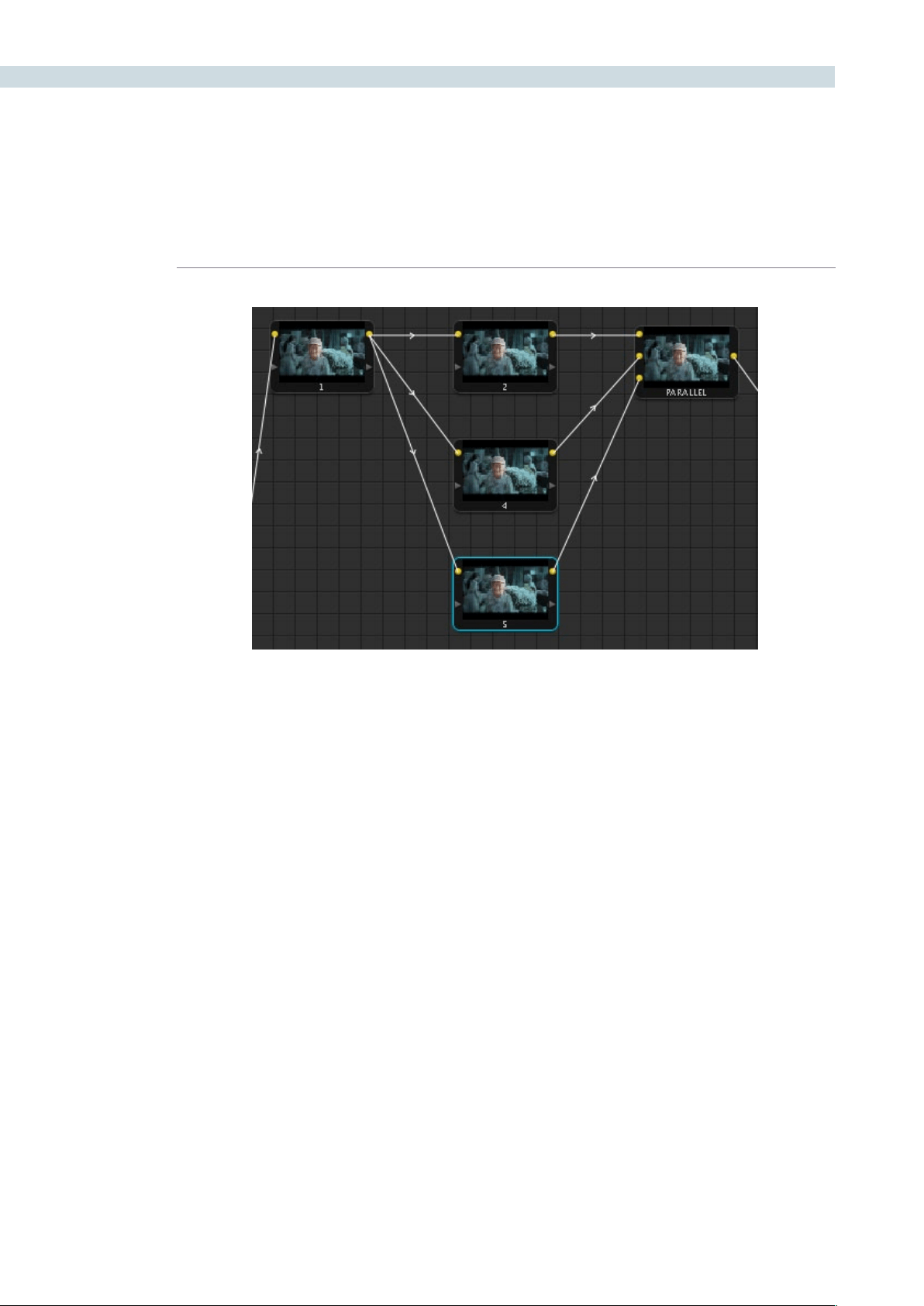
COLOR 202
The order in which nodes are connected in your tree effects the end result of a grade. For example, if
you boost the highlights in the first node, and then you try to isolate a portion of the picture in a second
node that you now realize has been clipped, you’re going to need to change your order of operations
to optimize your corrections.
To reorder two or more nodes:
1. Delete every link that connects the nodes you want to rearrange.
2. Drag the nodes into the new order you want them in the node graph (it pays to be
tidy), and then reconnect the RGB outputs and inputs until all of the nodes in your
tree are reconnected.
Rearranging Your Tree in the Node Graph
It’s a good idea to keep the arrangement of your nodes in the node graph clean and neat. It’ll make
it easier to read your tree if you need to revisit a grade later on, and it will also make it easier for other
colorists working on the same project to figure out what you’re doing. The following procedures describe
how to rearrange the nodes in your tree, and the node tree working area, to help you keep on top of
your grades.
To move a node to another position in the grid:
•Dragitwhereveryouwantittobe.
Any output can be connected to multiple inputs (node 1), but corrector inputs can only be
connected once (nodes 2, 4, and 5). Nodes intended for combining multiple images have
multiple inputs (Parallel node).

CHAPTER
COLOR
COLOR203
9
To expand the size of the node tree’s working area:
•Right-clickanywherewithinthenodegraph(exceptonanode)andchooseToggle
Display Mode.
The Viewer disappears and the gallery tabs are moved to the right, so that the node
grid is larger.
To zoom into and out of the node tree, do one of the following:
•Scrolluptozoomin,scrolldowntozoomout.
•Middle-clickanddragtomovethenodetreearound.
•Right-clickandchooseZoomInorZoomOut.
•Right-clickandchooseZoomtoWindowtotthenodetreetothecurrentsizeof
the node graph.
•Right-clickandchooseOriginalSizetoreturnthenodegraphtothedefaultsize.
Toggling Nodes On and Off
In the process of creating a node tree, it’s often useful to turn nodes off to disable their effect on your
grade. It’s also useful to turn the entire node tree off and on to get
Disabled nodes are not processed during rendering, and they remain disabled when you save that
grade along with a still in the Gallery and then apply that grade to another shot.
To toggle individual nodes off and on:
•Clickthenumberofanynodeinthenodegraphtodisablethatnodebyitself.
•Selectanode,andchooseNodes>Enable/DisableCurrent
•PressControl-D.
•OntheDaVinciResolvecontrolsurface,presstheDisableCurrentbutton(onthe
T-bar panel).
To turn every node off and on at once:
•PresstheUpArrowkeytoturnoffallnodes,andpresstheDownArrowkeytoturn
them on again.
•OntheDaVinciResolvecontrolsurface,pressSHIFT-DOWNandthentheDISABLE
CURRENT button (on the T-bar panel)
Note: When you turn every node off and then on again, every single node is re-enabled, even nodes that
had previously been individually disabled.

COLOR 204
Resetting Node Trees Using the Base Memory Commands
If you’re dissatisfied with your current set of operations and want to start over again, there are three
ways you can reset the node tree.
Base Memory:
Resets the currently selected node, eliminating all marks, to the default parameter
settings.
Base Memory All:
Resets every single node in the current node tree, without affecting the node tree’s
structure; all nodes remain where they were. However, each node has been reset to
the default parameter settings, and all marks have been eliminated.
Base Memory Reset:
Deletes every node and mark, and restores a single node set to the default
parameter settings.
Preview and Base Memory
There are also two other methods of quickly dealing with unwanted changes you’ve made to node
trees, without using undo.
Preview Memory:
Lets you preview the effect of any saved grade on the current clip. To preview,
choose Session > Preview Memory (Shift-Command-M), and then right-click any
saved still in the gallery (or memory) and choose Add Correction.
If you like the effect, then you can leave it be. If you don’t like the effect, then
choosing Session > Preview Memory again reverts the clip to the original grade.
Original Memory:
This command lets you quickly revert a clip’s grade to its original state when you first
selected that clip. This is useful for getting immediately back to a clip’s original grade
if you’ve made a series of changes that you then regret.
Please note that selecting another clip in the timeline and then reselect the clip you
made changes to resets what is considered to be the current grade.
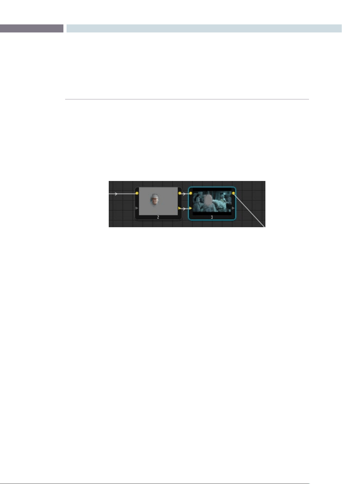
CHAPTER
COLOR
COLOR205
9
Outside Nodes
Whenever you use a Power Window or HSL Qualifier to limit a correction within one node, there is a
special node structure you can use to automatically create a second node that’s set up to correct the
inverse of the isolated region within the first. This is the Outside node, and Outside nodes make it easy
to apply separate corrections to an isolated subject and its surroundings.
In the following example, a woman’s face has been isolated using HSL Qualification, and an Outside
node has been added to make an additional correction to everything else within the shot.
To add an Outside node to a node creating a secondary correction:
1. Select a node that has been limited using a Power Window or HSL Qualifier.
2. Do one of the following:
•ChooseNodes>AddOutside
•PressShift-O
•OntheDaVinciResolvecontrolsurface,presstheADDOUTSIDEbuttononthe
T-bar panel.
A new node is created immediately after the selected node, and the RGB and Key outputs of the first
node have been automatically connected to its RGB and Key inputs. Within the new node’s Key tab, the
External Key group’s Invert checkbox is automatically on, which is what inverts the matte.
In this two node correction, node 1 isolates the woman’s face, and node 2 is an outside
node that is correcting everything but the face
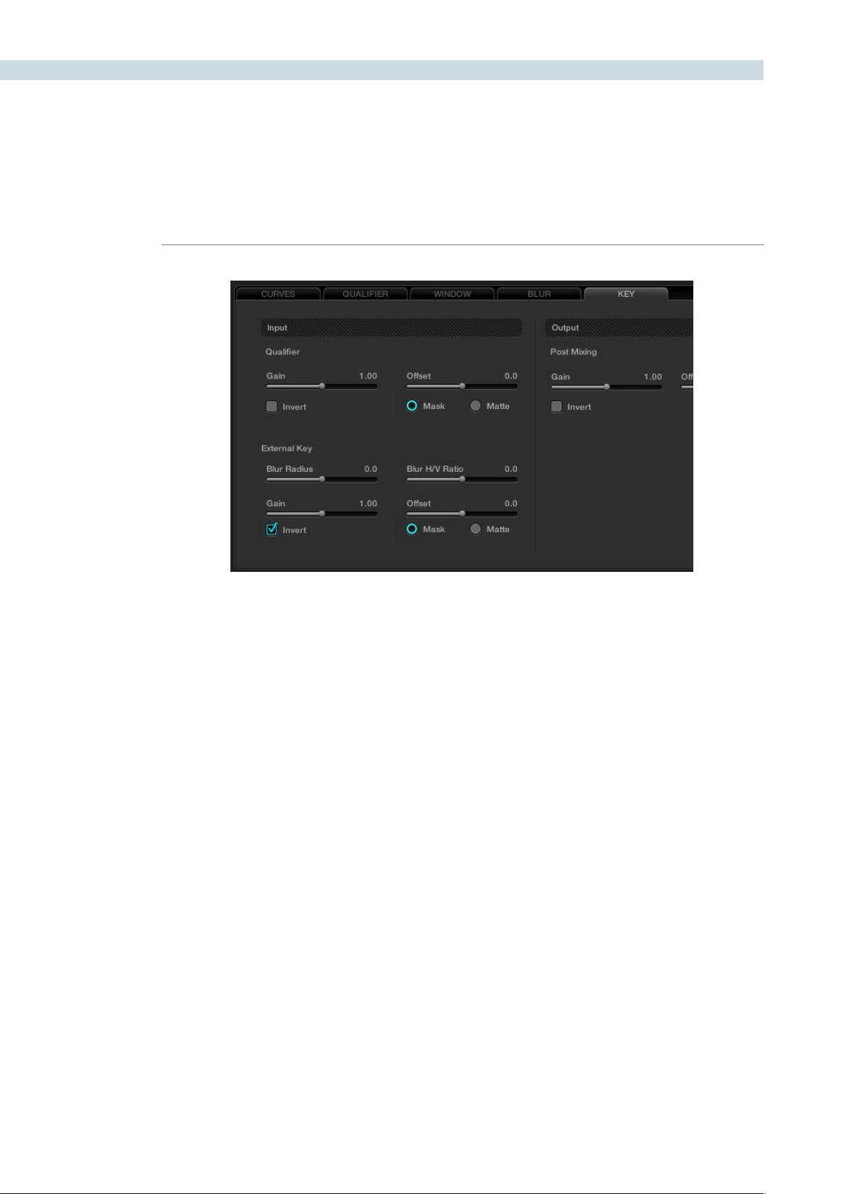
COLOR 206
Parallel Mixer Node
When nodes are connected one after the other this Serial or Cascade configuration effectively links the
output of the first node to the input of the next and so on until the last node, which finally links to the
Node Graph output. This is the point where the Viewer and Grading monitor is connected.
As each node modifies the image it changes the range of data available to the next node. An example
would be a node one that removes all the color in the image. Its output is a black and white image and
the following node only has this black and white image to work with. You can not add color on node two
by increasing the gain for any color channel as there is no color at the input as supplied by node one.
The External Key Invert checkbox, found within the Key tab
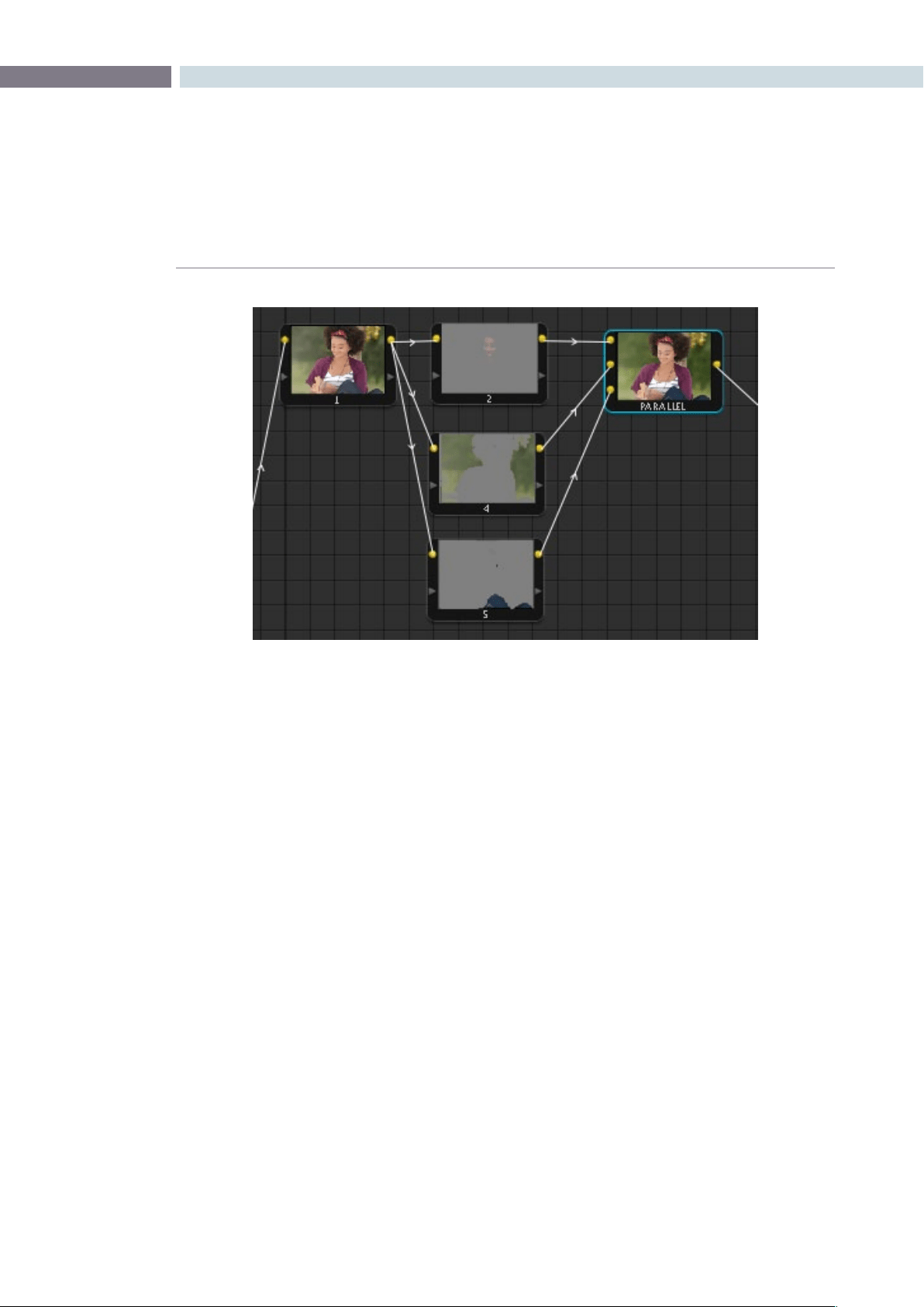
CHAPTER
COLOR
COLOR207
9
An alternative way to work is to put the nodes in parallel rather than in series. The nodes can then have
a common input, the full range data, and each can produce the individual enhancement and output to
a Parallel Mixer node.
The Parallel Mixer node is a multiple input and single output node for images. (There is a Key Mixer node
we will cover later.) When you add a Parallel node to an existing node, DaVinci Resolve will automatically
add one Corrector node below the current node and will also add a Parallel Mixer node. The current
node and the new Corrector node will have the same input source, which can be the original file source
or the output from another node. Both the current and the new Corrector nodes will have their outputs
connected to an input on the Parallel Mixer. If you add one more Parallel Corrector node the Mixer will
add another input.
A Parallel Mixer node will mix all the inputs with equal processing priority.
Layer Mixer Node
The Layer Mixer node appears at first sight to be similar to the Parallel Mixer in that it allows for multiple
Corrector node outputs to be mixed into one node. While the Parallel Mixer processes all the inputs with
equal priority, the corrections in a Layer Mixer are prioritized from top (least priority) to bottom (greater
priority). As you add additional Corrector nodes to the Layer Mixer they are placed with a higher priority
on the Node Graph below the preceding nodey.
Changing the position of the links that are connected to the Layer Mixer node inputs will change the
priority. You may also add additional inputs to the Layer Mixer node with a right mouse click on the
LayerMixernodeandselecting‘AddInput.’
Layer node operation is ideal when you have multiple inputs to the mixer and you want some to mask
others or have a greater influence over the mixed image.
Parallel Mixer
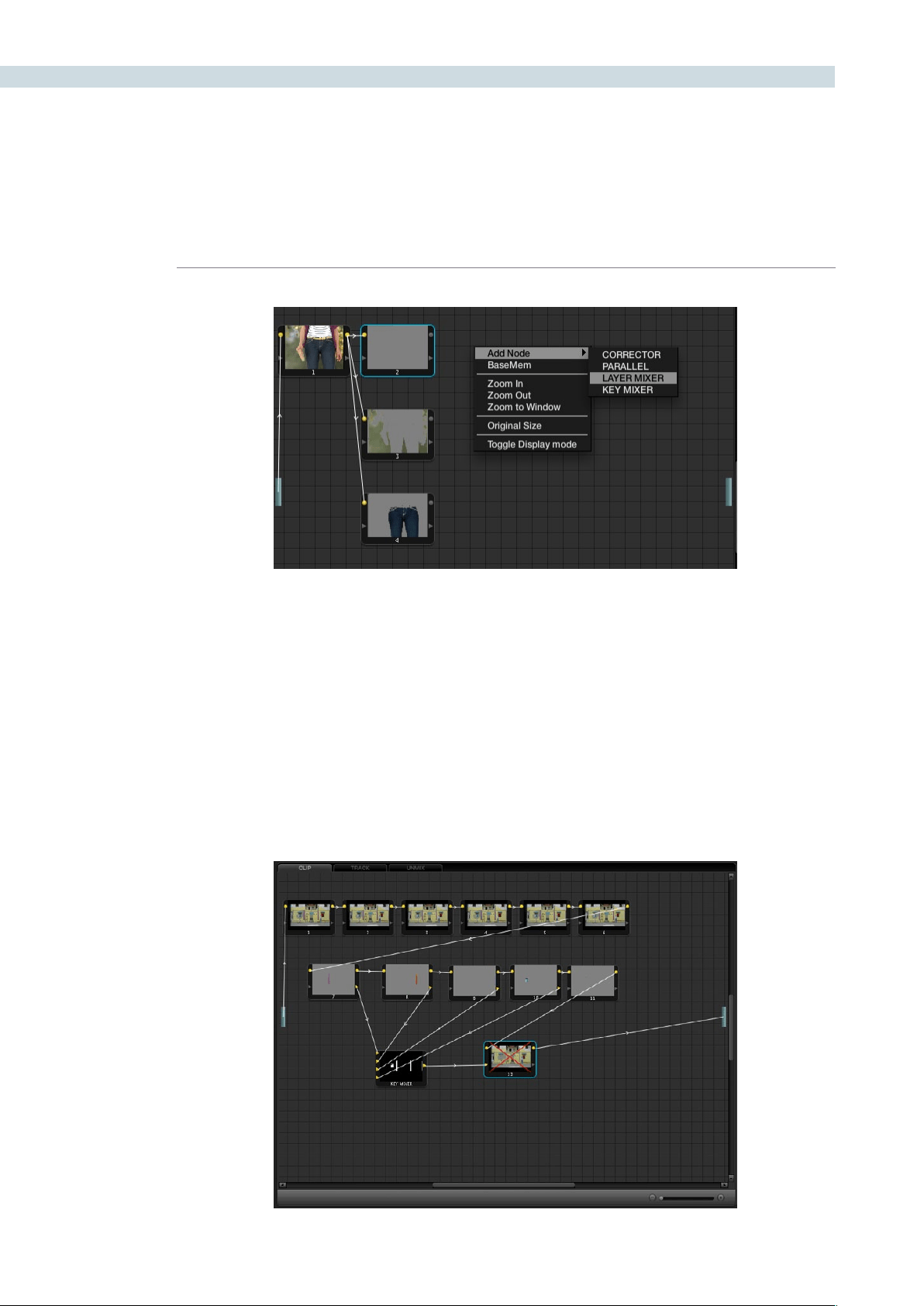
COLOR 208
Key Mixer Node
The Key Mixer node allows you to mix the key outputs from multiple nodes and combine them within
the Key Mixer node in order to produce a composite key signal. To create a Key Mixer node, right mouse
clickwithintheNodeGraphdisplayandaddaKeyMixernodebyselectingtheoptionwithinthe‘Add
Node’ section of the menu.
The Key Mixer node comes with two inputs when first created, but additional ones can be added with a
rightmouseclickwithintheNodeGraphdisplayandchoosingtheoption‘AddOneInput.’
To adjust the parameters of each node, which is fed into the Key Mixer node, use the Input section of
the Key tab. The Gain Control within the Post Mixing section can be extremely useful for adjusting the
amount of effect the final correction will have within the image.
Layer Mixer
Key Mixer Node
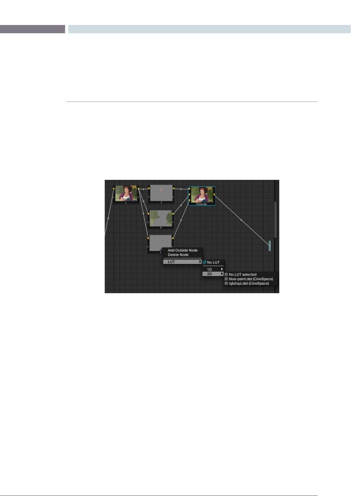
CHAPTER
COLOR
COLOR209
9
LUT applied within a node
You can apply look up tables (LUTs) to nodes within the DaVinci Resolve Node Graph display. Simply
right mouse click on the desired node and apply either a 1D or a 3D LUT from within the options
available in the menu. Applying LUTs in this fashion allows you to emulate various effects and can also
be used with the qualifiers.
The LUT list used here is the same as found on the Config screen.
Adding a LUT to a Node
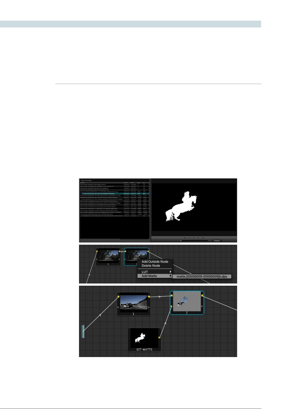
COLOR 210
External Matte Support
DaVinci Resolve supports unlimited external mattes within a clip. These external mattes must be linked
to the associated image within the Browse screen Media Pool. To recall the external matte within the
Color screen, right mouse click on the node within the Node Graph display and select the associated
matte file or press the M key on the DaVinci Resolve control panel keyboard.
Once the external matte has been associated you may apply a grading inside the defined area. If you
selectthe‘ExtMatte’nodewiththemouse,anewseriesofcontrolswillappearontheDaVinciResolve
control surface.
These controls allow you to adjust the matte for optimum results. A second key tab in the UI allows
further adjustments to position and size.
External Matte Support
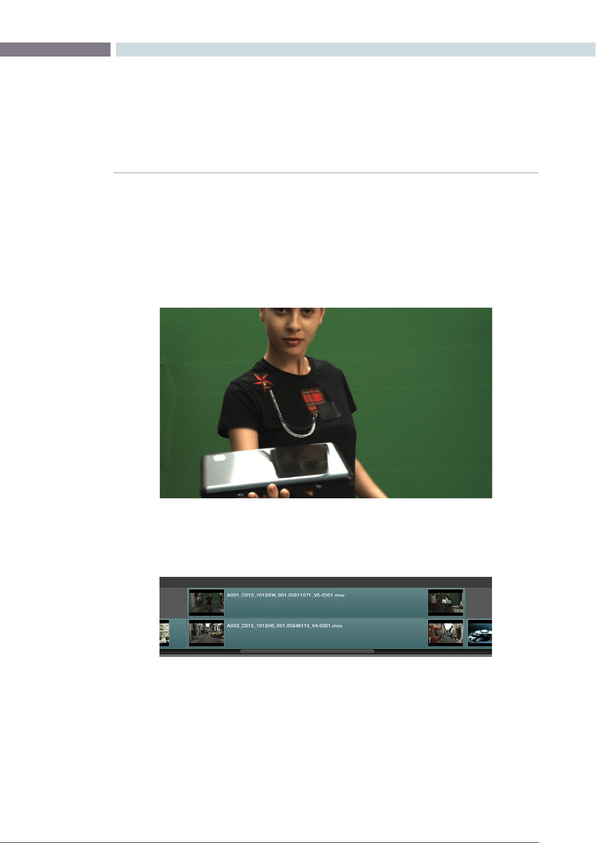
CHAPTER
COLOR
COLOR211
9
Compositing Using the Alpha Output
The Alpha Output is an optional output bar that you can turn on in the node graph, that appears
underneath the Output bar. The Alpha Output bar is useful for creating true transparency in a clip in
order to composite it with other clips on lower video tracks.
There are many ways of using the Alpha Output, but let’s focus on two examples. In the first one, we’ll
use the Alpha Output to composite a greenscreen clip with a background plate.
In preparation for this composite, the background plate is on track V1 of the Timeline, and the greenscreen
clip has been superimposed on track V2.
To create a chroma-key composite :
1. Right-click anywhere within the node tree working area and choose Add Alpha Output
from the contextual menu to add the Alpha Output bar at the left of the node graph.
An Alpha Output bar appears underneath the Output bar.
A greenscreen clip, ready for compositing
A superimposed greenscreen clip on track V2 of the Timeline, above a background plate
on track V1, ready for compositing.
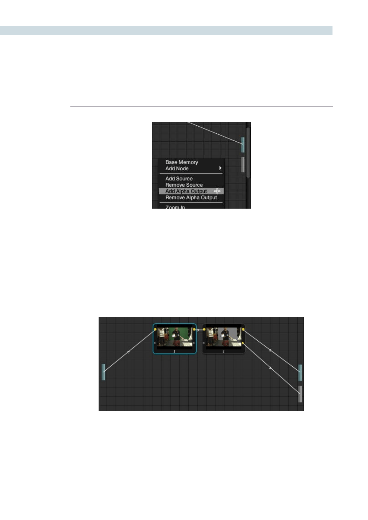
COLOR 212
The Add Alpha Output menu item, next to the actual Alpha Output,
located underneath the Output bar.
2. Add a serial node after node 1 and connect its Key output to the Alpha Output bar. This
is a fast way to build this composite if you’re confident that the corrections you’ve made
in node 1 won’t adversely affect the key, or if you know they’ll improve it by expanding
the contrast of a flat-contrast source clip.
Alternately, you could create a second processing branch by adding a disconnected
node (node 2), connecting the Source bar to its RGB input, and then connecting its Key
output to the Alpha Output bar you just added. Creating a second image processing
branch from which to pull your key lets you key directly from the Source, avoiding any
problems that grading the first node could introduce to the key.
3. Use the Qualifier controls of node 2 to key out the green background, and then turn on
the invert checkbox to create the proper composite.
4. If necessary, adjust the primary correction being applied in node 1, and make whatever
corrections are necessary to the background plate clip to make the composite blend
together more seamlessly.
Node 1 grades the clip, expanding contrast to improve both the image, and its ability to be keyed.
Node 2 uses Qualifier controls to pull the key.
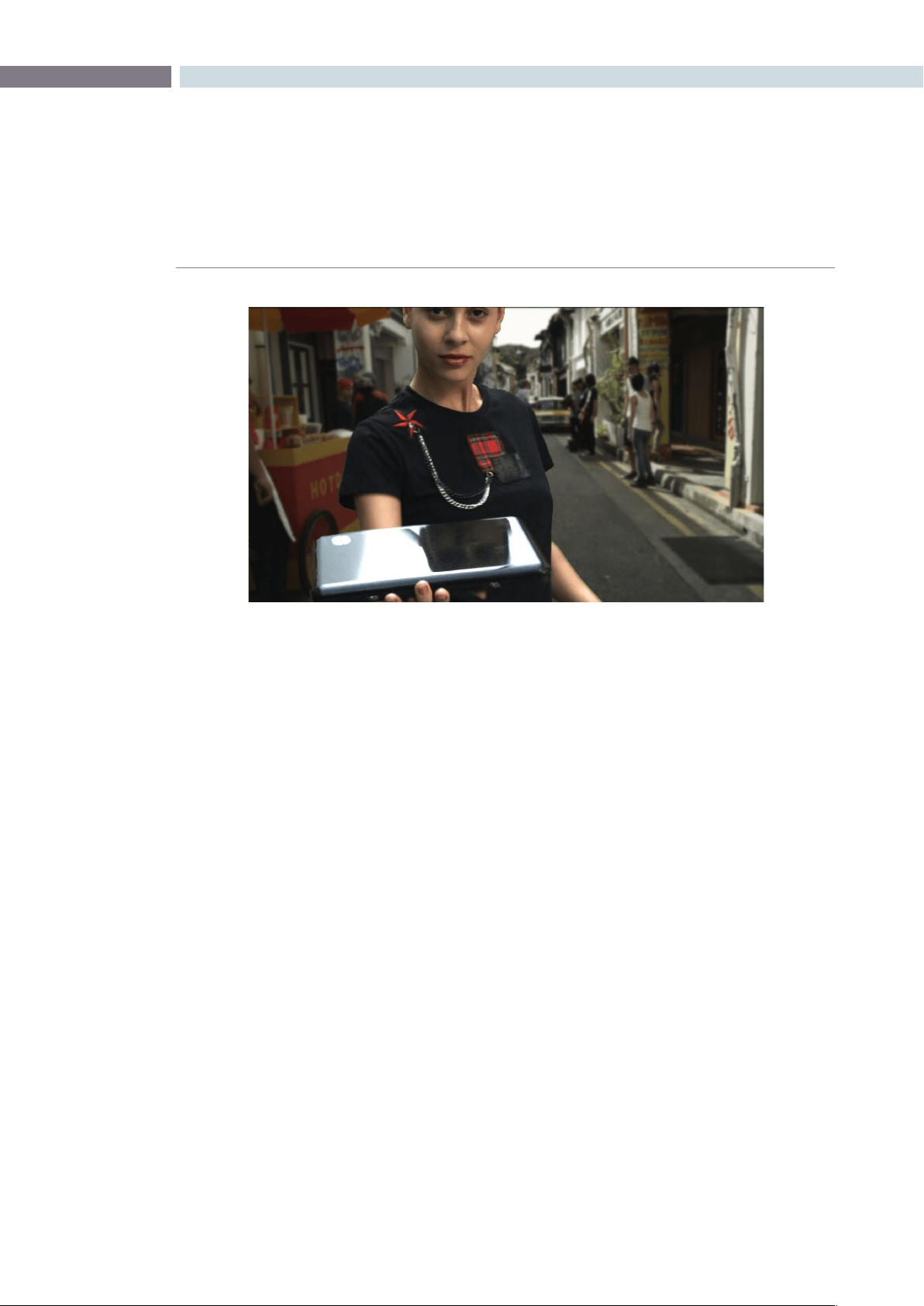
CHAPTER
COLOR
COLOR213
9
You’ve already seen that you can import an external matte clip to use for isolating clips in Resolve.
Although DaVinci Resolve isn’t compatible with embedded alpha channels, if you’ve exported a clip’s
alpha channel as a separate matte clip, you can use that matte clip with a superimposed clip to create
an identical composite using the Alpha Output.
To create a composite using an external matte:
1. To associate an external matte with a clip, open the Browse page, select the clip
you want to add a matte to in the Media Pool, navigate to the matte file using the
Media Storage and Clip Details lists, and then right-click the matte file and choose
Add as Matte.
2. Open the Color page and select the foreground clip in the thumbnail timeline, then
right-click node 1 in the node graph and choose the matte you added from the Add
Matte submenu.
An EXT MATTE node appears underneath Node 1, with the first of its three Key outputs
connected to node 1’s Key Input. Working with external mattes is covered in more detail
in a prior section of this chapter.
3. Now, right-click anywhere within the node graph, other then on a node, and choose Add
Alpha Output from the contextual menu.
An Alpha Output bar appears underneath the Output bar.
An initial chroma key composite, ready for refinement
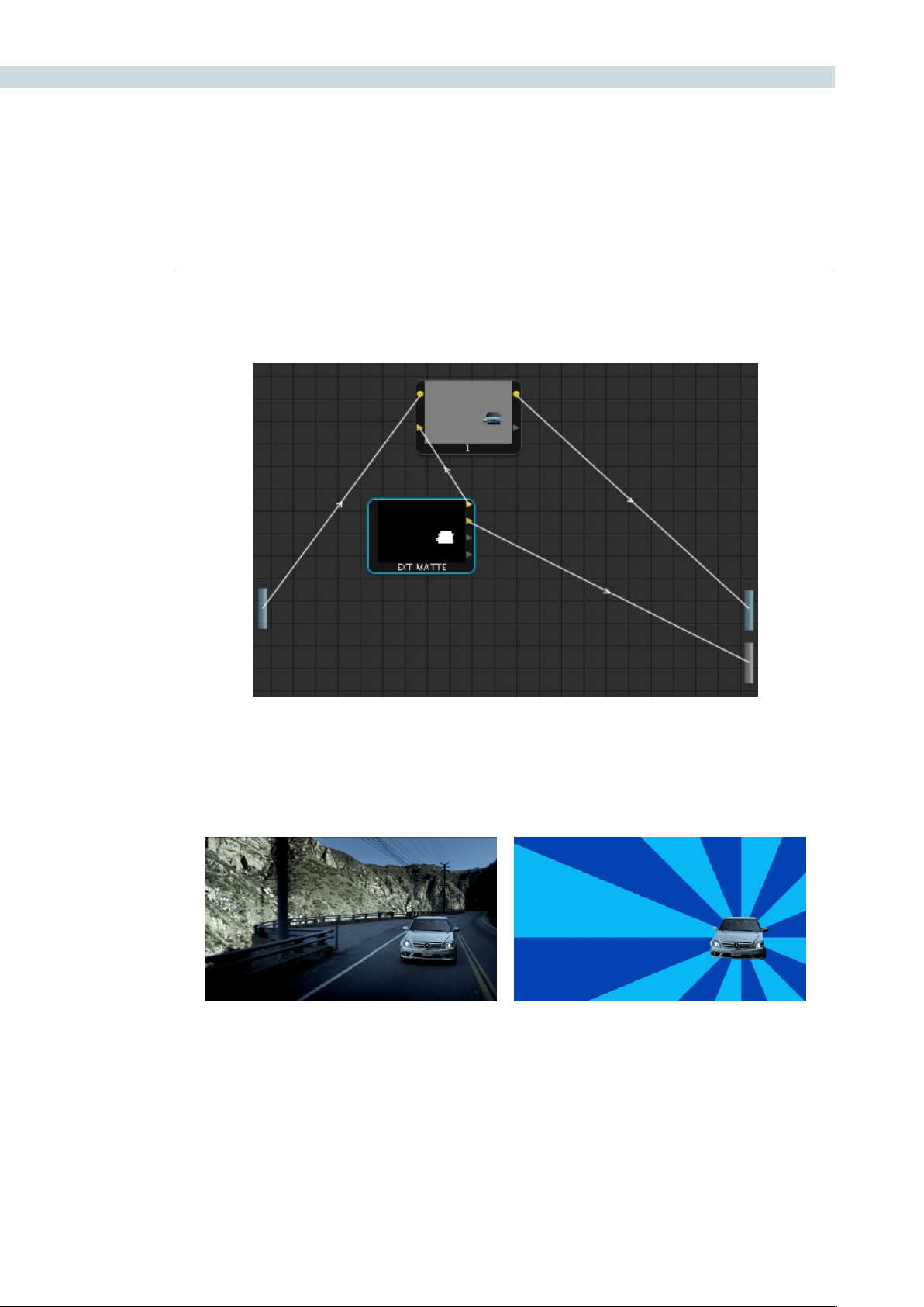
COLOR 214
4. Drag a connection line from the second Key output of the EXT MATTE node to the
Alpha Output bar.
You should now see a successful composite, with the external matte creating a region of transparency
in the foreground clip though which the background clip shows through.
Before and after the final composite, created by connecting an
Ext Matte node to the Alpha Output in the Node Graph
External Matte Support
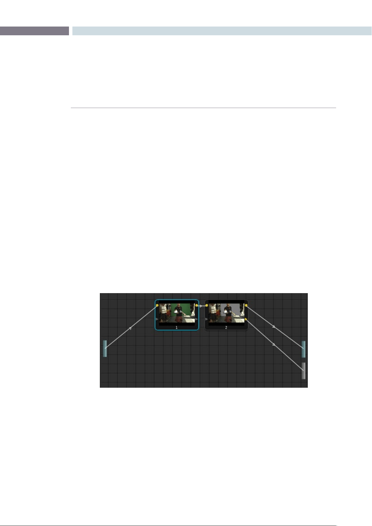
CHAPTER
COLOR
COLOR215
9
RED HDR Input Support
The RED EPIC and SCARLET cameras are capable of shooting in an HDR mode that effectively
“brackets” two different exposures of each frame. The resulting image data stores two channels of image
data; the regular exposure, and a “highlight exposure” that’s underexposed by a user-selectable margin
(+3,+4,+5,or+6ƒ-stopsdifference).
By default, the Input bar in the node graph feeds the regular exposure to your grade’s node tree. To
take advantage of the additional “highlight” exposure, you can add an additional Source input to the
node graph that feeds a second stream of image data that you can mix with the regular exposure in
different ways.
To set up a node tree combining the normal and highlight HDR versions:
1. Using the first default node (node 1), grade the image to see if you even need to use the
alternate exposure that’s available. We’ll assume for this example that you do.
2. Create a Layer Mixer node by choosing Nodes > Add Layer (Shift-L), or press the ADD
LAYER button of your control surface.
Two nodes are created, a Layer Mixer node that’s added after node 1, and a third node
(node 3) that’s connected to a second RGB input of the Layer Mixer node in parallel
to node 1.
3. Right-click anywhere within the node graph, except on a node, and choose Add Source
from the contextual menu.
A second Source bar appears underneath the first, which outputs the highlight exposure
of the image as a separate image stream.
Node 1 grades the clip, expanding contrast to improve both the image, and its ability to be keyed.
Node 2 uses Qualifier controls to pull the key.
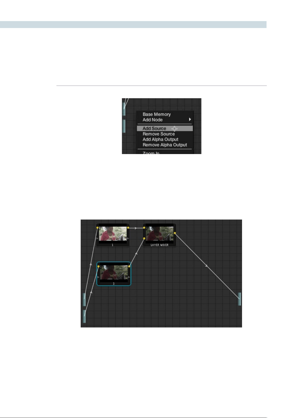
COLOR 216
4. Delete the connection between the top Source bar and node 3, and then connect the
bottom Source bar to the RGB input of node 3.
Immediately, the image in the node thumbnail and Viewer updates to show the darker,
underexposed version of the HDR image. This is because, by default, the Layer Mixer is
mixing 100% of node 3 over node 1.
A node tree that uses a Layer Mixer node to mix two Corrector nodes, each connected to
separate Outputs for the regular and highlight exposures.
The second Source bar, next to the menu command
that creates it
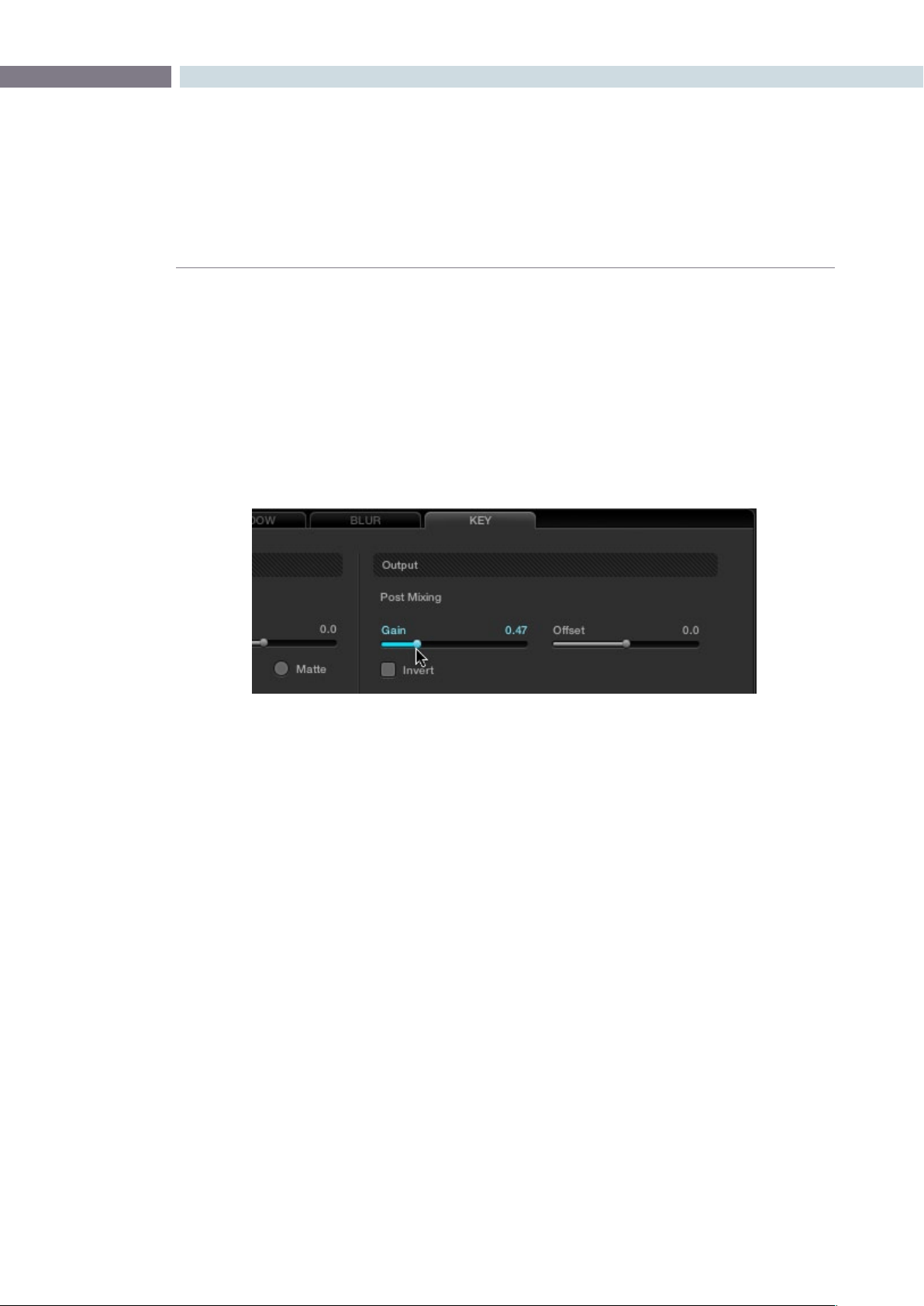
CHAPTER
COLOR
COLOR217
9
5. Select node 3 and use one of the following two procedures to create a useful combination
of the two exposures:
•Tocreateamixofthetwoexposures,opentheKeytab,anddragthePostMixing
Gain slider to the left to lower the contribution of node 3 to the overall image (you
can also do this using the DaVinci control panel by pressing the KEY MODE soft
button, and then using the Post Mix Gain rotary control). Using dynamics (keyframing),
this is a good way to animate a dissolve from the regular exposure to the highlight
exposure if you’re going from a dark environment to a bright environment in the
same take and you want to create a smooth transition between both exposures.
•Tousethehighlightexposuretoselectivelyputdetailbackintotheimage(for
example, to retrieve blown-out windows), use a Power Window, HSL Qualification, or
a combination of the two to isolate the region you want to retrieve in node 3. Be
careful if you’re using HSL Qualification to combine both exposures, as keyed edges
can be tricky to blend.
Dissolving between the regular and highlight exposures of RED HDR media using the Post
Mixing Gain slider of a Corrector node connected to a Layer Mixer node.
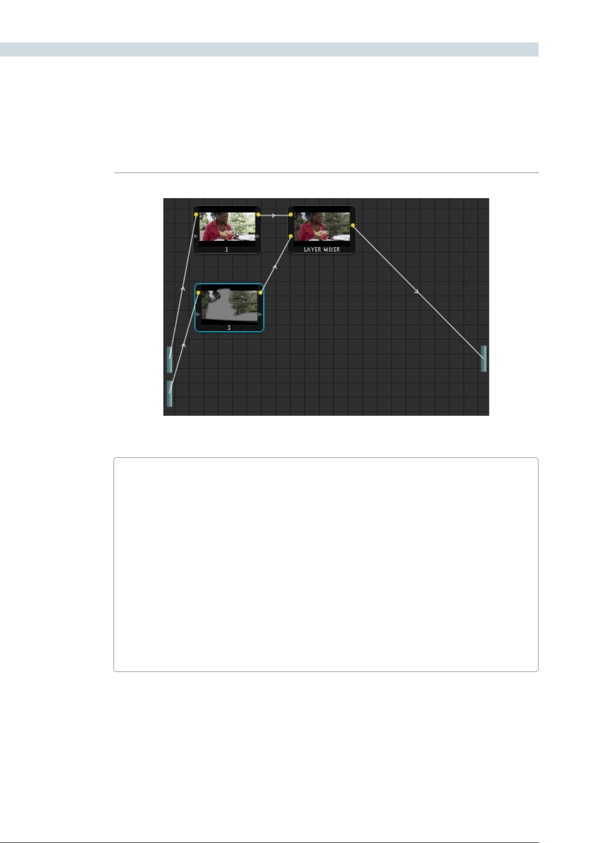
COLOR 218
Isolating a region of the image to replace using the highlight exposure image of a RED HDR clip
A Note About RED HDR Media and Performance
Since RED HDR media records two complete streams of image data, DaVinci Resolve must
simultaneously decode two separate tracks whenever you add a second Source bar. If you
don’t add the second Source bar, only the first stream is decoded.
Because of this, whether you’re relying on your computer’s CPU to decode RED media, or
you’re using a single RED ROCKET card, you’ll get half the performance when using the
highlight stream of an HDR clip.
To improve performance, you can set any RED HDR clip’s Render Cache Mode to “User” by
choosing Session > Render Cache Mode, pressing Option-R, or pressing the CACHE MODE
button on the T-bar panel of your control surface repeatedly until you toggle to User mode.
DaVinci Resolve renders all cached clips in the background, so the next time you play a cached
clip, it will play at full speed.
If you regularly use RED HDR media, two RED ROCKET cards are recommended for optimal
decoding performance.
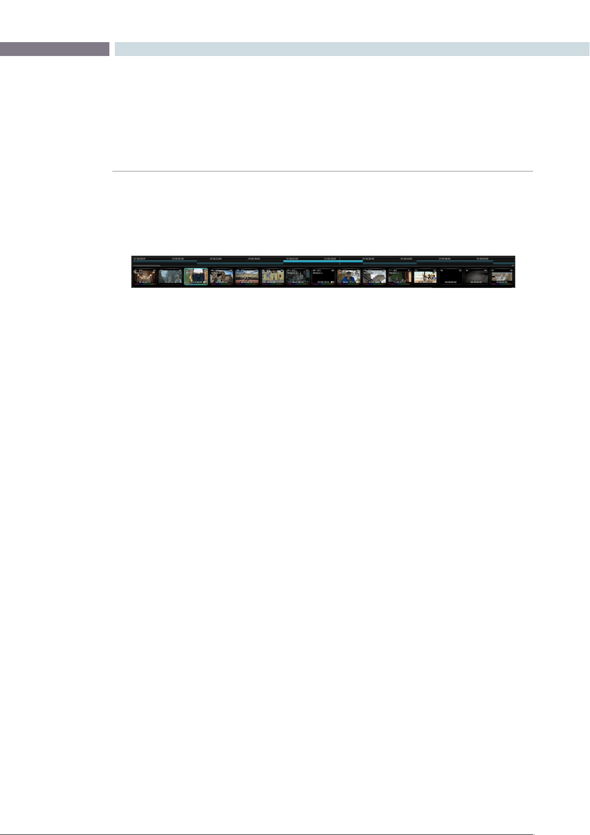
CHAPTER
COLOR
COLOR219
9
Directly below the Viewer, Stills, and Node Graph display is the timeline which shows all the clips in
timecode ascending order. The timeline can be sorted in Source (C-Mode) or Record (A-Mode) order.
In Source mode, no EDL is considered as all clips are placed one after the other in timecode ascending
order, complete with holes in the continuity of the timecode.
In Record timecode order (A-Mode), the EDL defines which clip is placed first and the following clip
order. Each clip is not only sorted for order, but the in and out points of each clip are use to define the
clip length. If there is a dissolve between two clips this is also displayed in the timeline. Change the
sortmodeofthetimelinebyselectingthe‘CommandPageDown’buttononthekeyboardtoselect
theRecordorA-Mode.Selectthe‘CommandPageUp’buttononthekeyboardtodisplayasourceor
C-Modeorderofclips.IfSourcemodeisselected,theword‘Source’willbedisplayedontherighthand
end of the timeline.
The white vertical line shows the current position along the timeline and this matches the frame displayed
intheViewer.Whenyouselect‘Play’onthecontrolpanel,ormouseontheUI,orusethespacebaron
the keyboard, you can then play the various clips one after another within the Project. The current clip
is highlighted for easy identification.
If you are in Loop mode the timeline will also display in and out markers and a highlight showing the
frames that are in loop play. You can also scroll through the various clips by dragging the vertical white
line back forth across the timeline or jump to another clip by clicking on the timecode portion of the
timeline. The vertical white line will jump to that location.
Below the timeline is a scroll slider that is used to expand and contract the timeline so you can zoom in
to review a single scene or expand to see the whole Project.
Clip Thumbnails/VSRs
Located directly below the timeline scroll slider are the Clip thumbnails. The current clip will have an
outline. When the Project has more than 15 clips, the current clip will be positioned in the center of the
clip thumbnail display with thumbnails either side, indicating the clips on either side of the current clip,
regardless of the length of those clips. If you click with the mouse on a thumbnail, this will automatically
cue, or jump, to this clip.
Timeline
Timeline with clip thumbnails
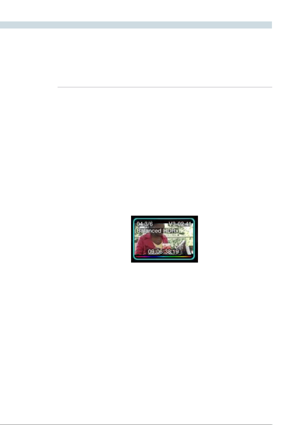
COLOR 220
Correction Management with the Thumbnail Timeline Display
When any type of correction is applied to a clip, metadata for the change is automatically saved for
the clip into the clip thumbnail. You can copy any corrections from one clip to another by recalling a
Memory, a clip number or even by scrolling to another clip, making it current, and copying the correction
to the new clip using the center mouse click.
Clip Thumbnail Indicators
In addition to displaying the color corrected image in the clip thumbnail, each thumbnail has a number
of other valuable indicators of the clip and operational status.
The clip number can be seen on the upper left of the thumbnail. If there are multiple versions of the
grade for this clip the numbers to the immediate right of the clip number will show the current version
number and how many versions there are. In the screen capture below there are six versions of grade
and version three is current. Under these numbers is the version name. If you have entered one, in this
case “Balanced HDRx”, this same location would also indicate a local or default version if alternatives are
made. See Versions later in this chapter for additional details.
Clip Thumbnail
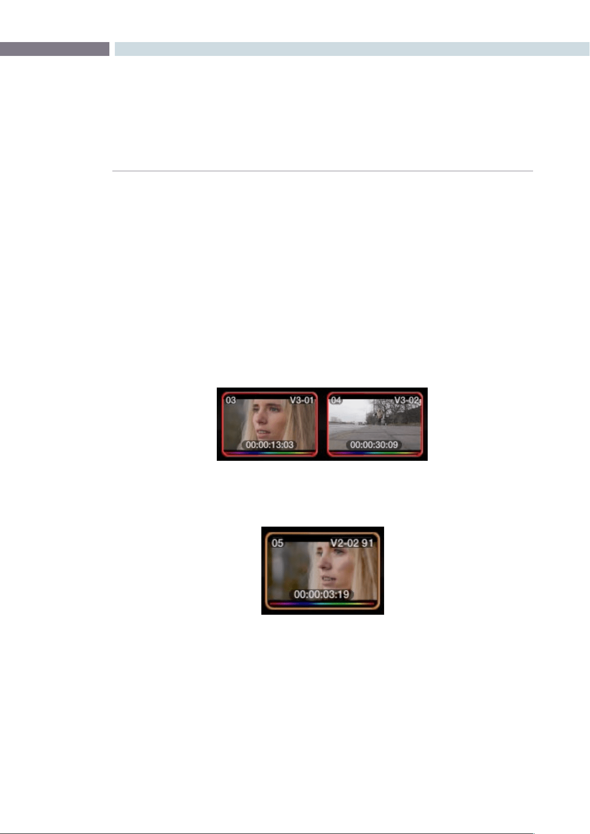
CHAPTER
COLOR
COLOR221
9
On the upper right of each thumbnail, you will see the Track number and the clip number in that track
followed by the frame number of the current frame if anything other than the first frame is shown. In
the case shown above, we are seeing frame 41. If you click and drag the mouse back and forth over the
thumbnail, you can view the contents of that clip within the thumbnail and even leave it parked on a
specific frame. This is particularly helpful to locate the key frame, or move off the first frame if its black,
or does not represent the key element of the scene. The frame indicator will update accordingly.
At the bottom of each thumbnail, DaVinci Resolve displays the timecode for that frame of the clip. This
timecode updates as you scrub over the clip. Below the timecode there may be a white box. This is
displayed if the colorist selects the Render Cache mode and it indicates the progression of the render
cache for this clip. You may also see a colored rainbow line at the bottom of the thumbnail. This line
indicates that the clip has had some alteration from the raw default settings. The rainbow is a quick and
clear indication of those clips not at default, and will therefore need attention.
The clip thumbnails may also have a red outline. This indicates that these clips are in a group and
grading changes to one are automatically made to the others.
Normally, Colorists compare the current shot to a Gallery Still or to the offline video, but you can select
any clip on the timeline to be the reference.
When you are working on material that has been conformed based on an EDL, certain clips may be re-
used within the EDL. For example, part of the whole clip may contain material which is needed for one
part of the EDL conform, however, another part of the same clip may contain material that is required
for later parts of the EDL conform. When this occurs, you will see a small red box located at the upper
center of the clip thumbnail. Whichever clips contain this red block will share the same correction as it
is the same clip.
Red outline indicates grouped clips
Orange outline indicates the
clip used for reference wipe
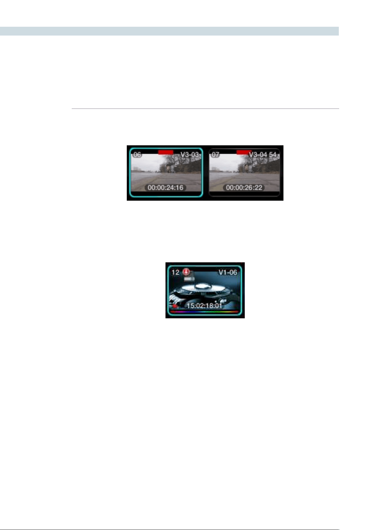
COLOR 222
Localversionsofthisclipcanbemadeatanytimebytheright-clickselection‘LocalVersion.’See
’Versions’ later in this section for a description of adding new and switching versions.
Justtotheleftofthetimecodeyoumayalsoseearedbox.Thisidentiesclipsselectedforrestoration
by a DaVinci Revival system. The red box is shown when the clip is selected, at the same time the Revival
screen lists the actions requested.
If you have selected a clip for render cache, a disc icon will be placed on the top left of the thumbnail.
Common Source Clip Indicator
Render Cache Indicator
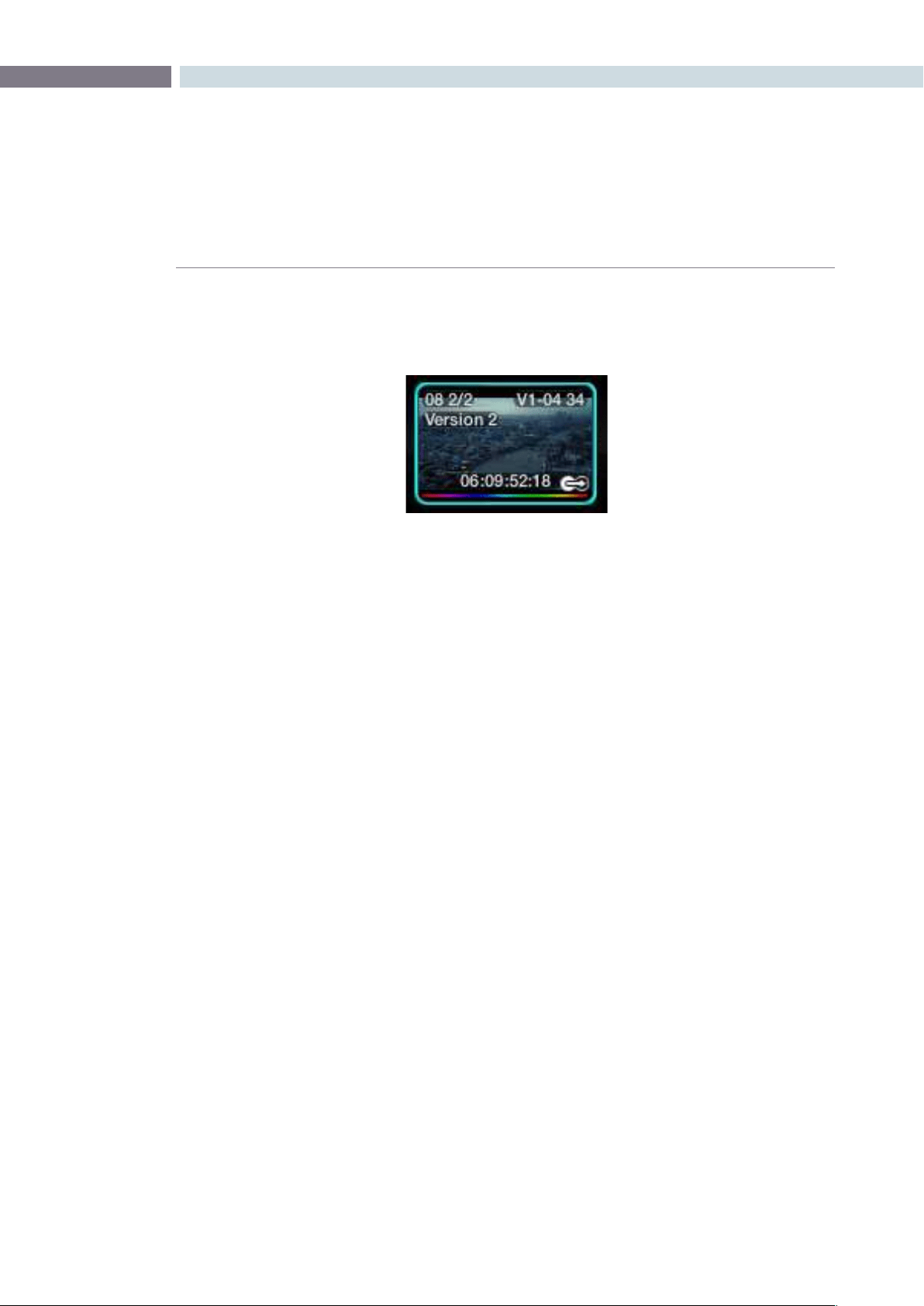
CHAPTER
COLOR
COLOR223
9
On the right of the thumbnail you will occasionally see the Tracker indication. This identifies that this clip
has Object Tracking. If you have modified the clip length it is a useful reminder to check that the track
now covers the complete clip.
Local and Remote Versions
There are a number of time saving right-click options within the clip thumbnail.
When the project images in the Media Pool are first conformed, you generate a default session or
defaulttimeline,calledtheMasterSession,usingthe‘CreateDefault’buttonontheConformscreen.If
there is an EDL, that is loaded afterwards, the EDLs will be listed by their names after the Master Session
in the EDL file label section on the Conform screen. When you work with the Master Session within
the Color screen, any color corrections that are made to any clip will be automatically applied to the
other conformed sessions (other EDLs), regardless of the order of the clips in those EDLs. This will save
you quite a lot of time as you can grade many different versions of the EDL automatically, and when
changing EDLs using the same clips, all of your grading metadata is automatically applied to the new
session/EDL.
When you are working on the Master Session but want to create an alternate version of a color
correction, the new version is called a new Local Version (i.e., you want to keep the original version but
also have another). As this is the Master Session, these versions are also available for use within the other
conformed sessions (other EDLs), but are listed as Remote Versions in those EDLs. This allows you to
keep a Master Session grade which is valid for most sessions but also have one that is just for a specific
session (e.g., for the Trailer).
If you are on a session other than the Master Session, you can make Local Versions that will be available
only for that session, or Remote Versions that will be available for all the other sessions (except for the
Master Session where it will listed it as another Local Version).
Every Remote Version of a grade made on every session relates to the Master Session, so if you render
each Master Session grade you will have the graded versions for all the various sessions.
Tracker Indicator
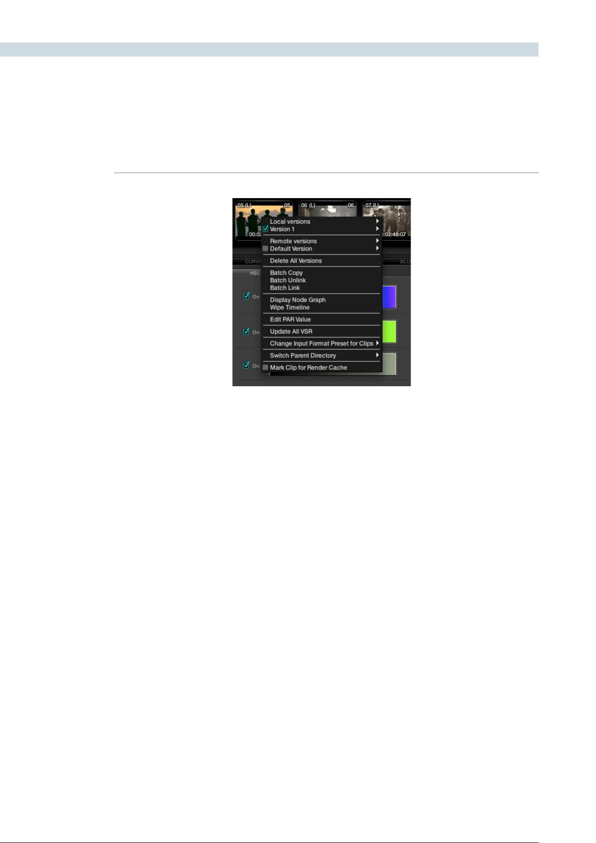
COLOR 224
When you access the New Local Version option from the timeline thumbnail pull-down menu, it will first
prompt you for a name for this version. Versions of grades can be loaded, deleted, named and selected
using the right-click pull-down menus.
You can create additional versions of corrections that have been made for a particular clip. Each version
will be available by right mouse clicking on the clip and selecting the version. You may also de-select
a batch version of a conformed list that can then contain an alternate version of corrections. These
additional versions can be named and the names are displayed in the clip thumbnail.
Group Versions
If you have multiple clips that share the same color correction, you can define a Group by right clicking
onaclipandselecting‘AddIntoANewGroup.’EntertheGroupNameandyouwillseeitinthegroup
list at the bottom of the pull-down menu. To add multiple clips, hold down the Ctrl key on the keyboard
andselectthevariousclips.Oncethelastclipisselected,use‘AddIntoCurrentGroup’fromthepull-
down display.
When there are changes to the correction that are to be applied to the Group, you can select how the
correction will be rippled to the various clips within the Group. Right mouse click on a clip within the
Group, then within the pull-down menu choose the appropriate Group Name and move the mouse to
the‘ChangeRipple’selection.Oncethishasbeendone,anothermenujoiningthesemenuswillappear.
This menu will give you the opportunity to change the ripple type, to make the target clip the exact
changed value, or make the change by percentage or unit value, or to have all values copied, as defined
in the Configuration screen settings tab.
Timeline right-click option
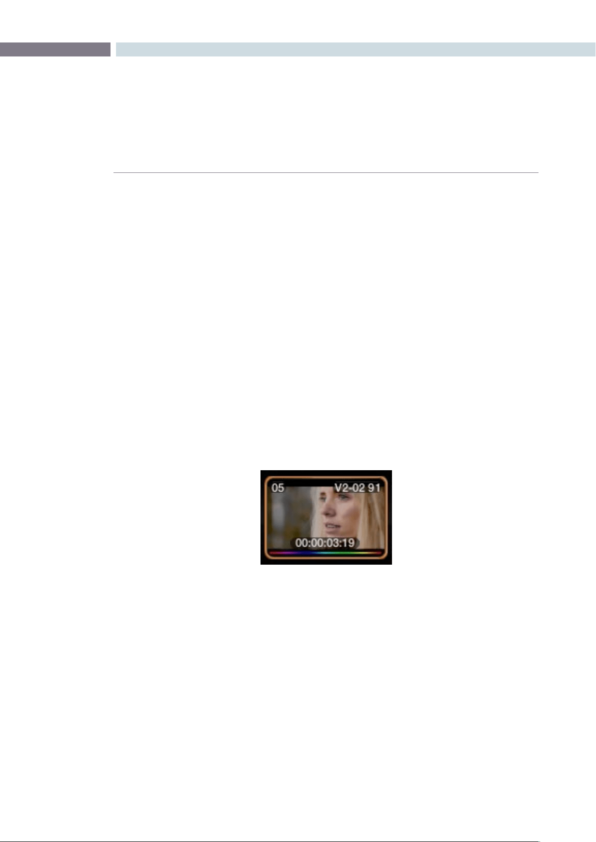
CHAPTER
COLOR
COLOR225
9
Batch Versions
When you begin to color correct using the Master Session, all corrections are automatically applied
to the other conformed versions. This means that the Master Session is Batch Linked to all the other
conformed versions. If you wish to create a different version of the color correction in another timeline,
simplyselectthedesiredversion,rightmouseclickonathumbnail,andselect‘BatchUnlink.’This
conformed version will not share the same color corrections as the Master Session or any of the other
conformedversions.Ifyouselect‘BatchLink,’thecorrectionswithinthisconformedversionwillrevertto
the corrections seen in the other conformed versions.
Batches may also be copied using this right-click option.
Display Node Graph
JustasyouselectedtodisplaytheNodeGraphfromStillsorPowerMasterStills,youcandosofromthe
timeline Thumbnail.
Wipe Timeline
The thumbnail will display an orange border indicating it is the active reference. Right click on a non
current thumbnail and select Wipe Timeline Scene to select or deselect. When you deselect the clip the
Gallery becomes the reference.
Update All VSRs
Toupdatethethumbnailimagesselect‘UpdateAllVSR’.
Edit PAR Value (Pixel Aspect Ratio)
The PAR (Pixel Aspect Ratio) setting in the Media Pool will always have an indication, either square or
one of the other many PAR formats offered. To change the PAR for any clip, select the Thumbnail with
the right-click option, then select Edit PAR Value and then select the appropriate PAR from the pop-
up box.
Orange outline indicates the clip used for reference wipe
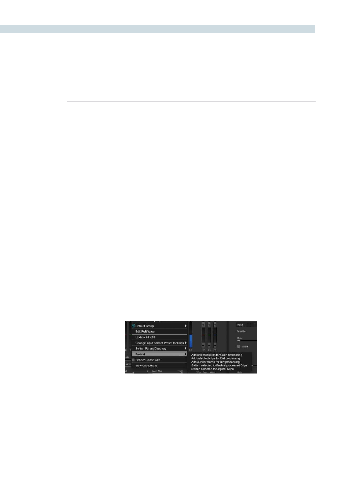
COLOR 226
Change Input Format Preset for Clips
To set Input and Output Format Presets that can be used with Session clips and apply as global presets,
make the changes from the Configuration screen or for Clip presets, within the Media Pool. Presets
can also be applied from within the Format screen, or as identified here, by right mouse clicking on a
thumbnail within the Color or Format screen.
These are pre-defined settings for various image scans and are useful, for example, when a film has been
over scanned. Instead of having to resize every clip independently, the user can resize a clip and use the
presettoapplytoall.Ifyouselect‘None,’thiswillindicatethatnosettingshavebeenapplied.
Switch Parent Directory
With a pre-conform workflow, there are often different versions of conform available on the SAN in
separate folders. DaVinci Resolve allows easy toggling between different versions of conform using
switchable Parent Directories.
Thefunctioncanbeaccessedusing‘SwitchParentDirectory’fromright-clickmenusintheMediaPool
and the Conform Panel, and also from the Color screen timeline.
DaVinci Revival
DaVinci Resolve image storage can be shared with a DaVinci Revival system. In this configuration the
Resolve operator can select a clip for action by the Revival operator.
The options are: Add selected clips for Grain processing, Add selected clips for Dirt processing, Add
current clips for Dirt processing, Switch selected to DaVinci Revival processed clips, and Switch selected
to original clips. Revival will only process DPX images so to send images to DaVinci Revival for processing
you need to render non-DPX images first.
When the DaVinci Resolve operator sends a clip to DaVinci Revival for Grain or Dirt processing, a red
indication on the thumbnail to the left of the timecode will indicate the request has been sent. The
DaVinci Revival screen on DaVinci Resolve will list this and all other requests.
Further information on DaVinci Revival operation is available from the DaVinci Revival User Guide and
there is more information on the interface with DaVinci Resolve in the DaVinci Revival chapter later in
this guide.
Timeline Right Click – Revival Options
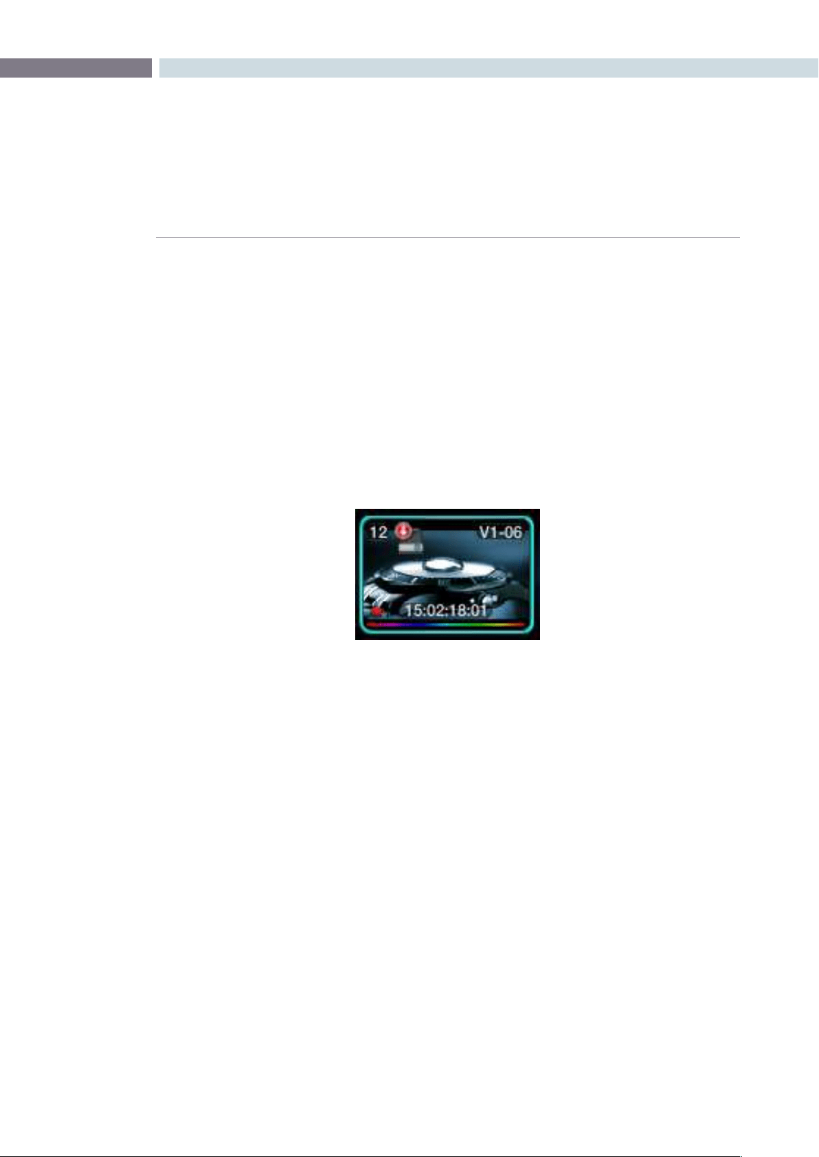
CHAPTER
COLOR
COLOR227
9
Render Cache Clip
DaVinci Resolve has a number of Background Render Cache options and one of these options is where
the user selects to render cache a clip.
The user may flag clips that should be render cached within a Project. This can be done by right mouse
clickingontheclipandselectingthe‘MarkforRenderCacheU’optionfromthemenu.Theharddisk
icon will appear on the top left-hand side of the thumbnail when the clip is selected by the user to
be cached.
When the cache process is started by the user, a status indicator at the bottom of each thumbnail will
show the progress of the cache generation process. The bar will first appear in white and the length of
thebarrepresentstheamountcompleted.Clipsmarkedfor‘RenderCacheU’willrenderif‘CacheU’or
‘Cache+’or‘CacheAll’isselected.
A clip that has been flagged
to be Render Cached
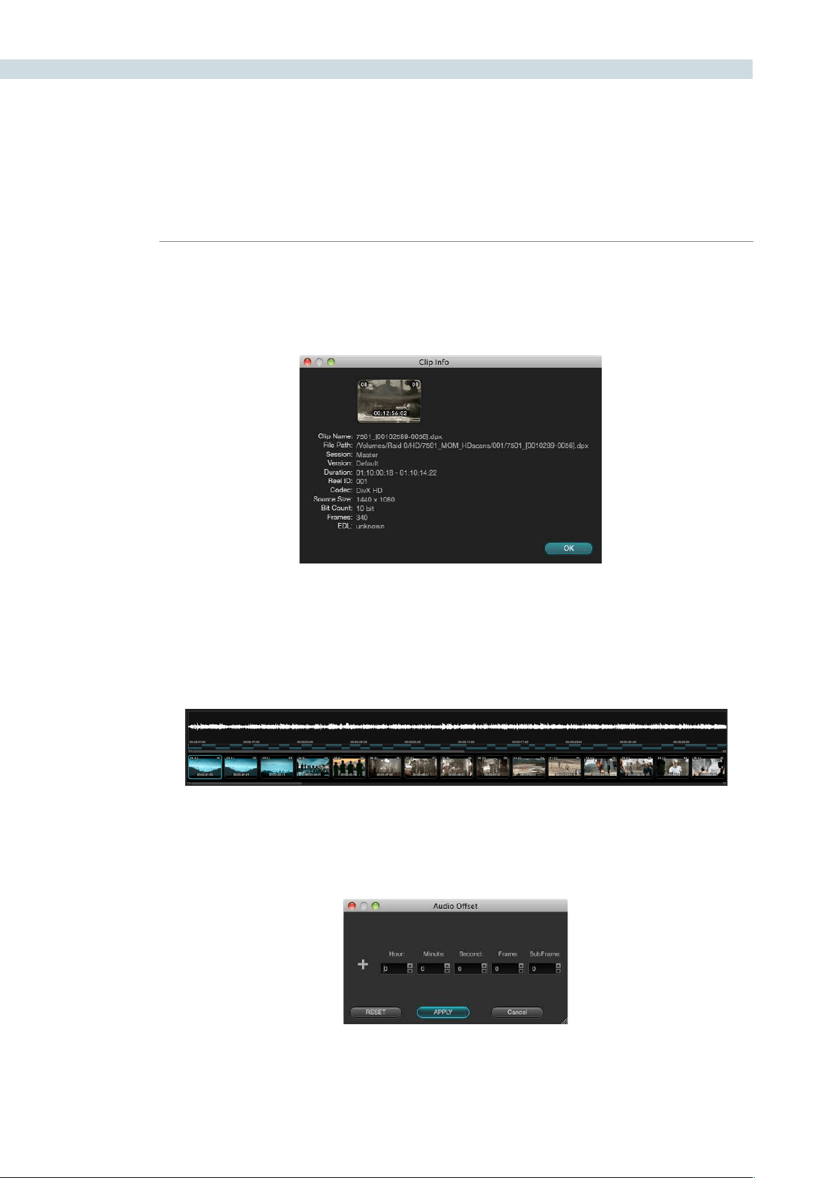
COLOR 228
View Clip Details
DaVinci Resolve maintains metadata relating to all clips in the Media Pool. This info is accessible using
the View Clip Details option.
Audio Timeline
While DaVinci Resolve is a color correction and enhancement system, it does play back guide audio.
When a .wav or AIFF file is selected in the Conform screen to play with an EDL, the audio can be
displayedontheColorscreenbyrightclickingonthetimelineandselecting‘ShowAudioWaveform.’
The waveform for the audio track can be slipped in time to sync the audio to video by using the control
key (Command in Mac) and the mouse to drag the clip up and down the main timeline. Alternatively,
youcanselectthe‘AudioOffset’dialogboxwitharightclickontheaudiowaveformandentertheoffset
you need.
Clip Info
Timeline with Thumbnails and Audio
Audio Offset
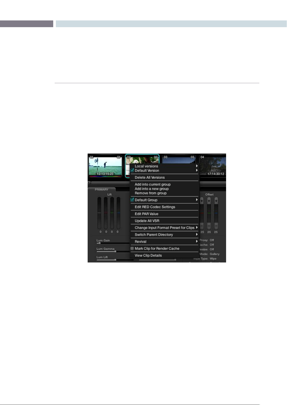
CHAPTER
COLOR
COLOR229
9
RED r3d Clip Decoder Control
DaVinci Resolve offers native RED r3d decoding. In the Configuration screen Source tab you can
select to use the RED Default decoder settings, the camera metadata, or set project based decoder
parameters for DaVinci Resolve to decode and debayer the r3d files. On the Color screen you also have
an extra layer of control, a clip-by-clip control.
IfyourtimelinehasREDles,rightclickonthethumbnailtorevealtheoption‘EditREDCodecSettings’
and this will open the decoder control window.
Color screen Thumbnail Right Click to select Edit RED codec settings
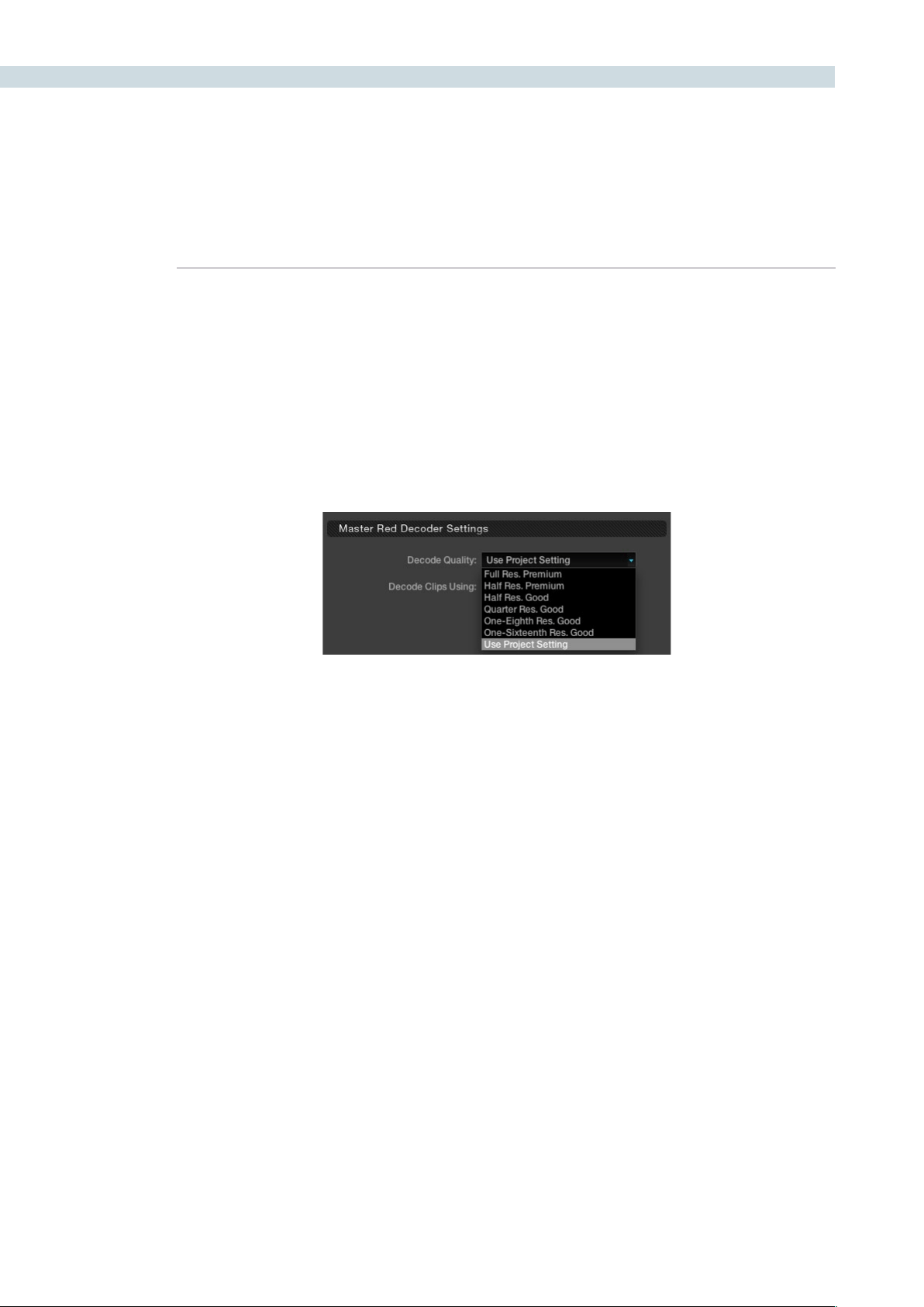
COLOR 230
Master RED Decoder Settings
There are three sections to the decoder window. The first is on the top left of the RED Settings window;
the configuration here sets the operation for the balance of this window.
The Decode Quality setting can be set to use the Project setting as selected on the Configuration
screen, Source tab for RED, or you can select one of the other debayer and resolution settings. These
settings include Full Resolution with Premium Debayer, to Half Res Premium (as often used for grading),
down to the One-Sixteeneth Res with Good debayer, which is often used when grading RED files on
a MacBookPro.
As you assign the decode quality you will have a direct impact on the performance of the system, so
you may want to grade in a resolution which provides real-time playback, then use the config settings to
switch to a higher quality/resolution for rendering. This will depend entirely on the hardware capabilities
of your system.
Color screen Thumbnail Right Click to select Edit RED codec settings
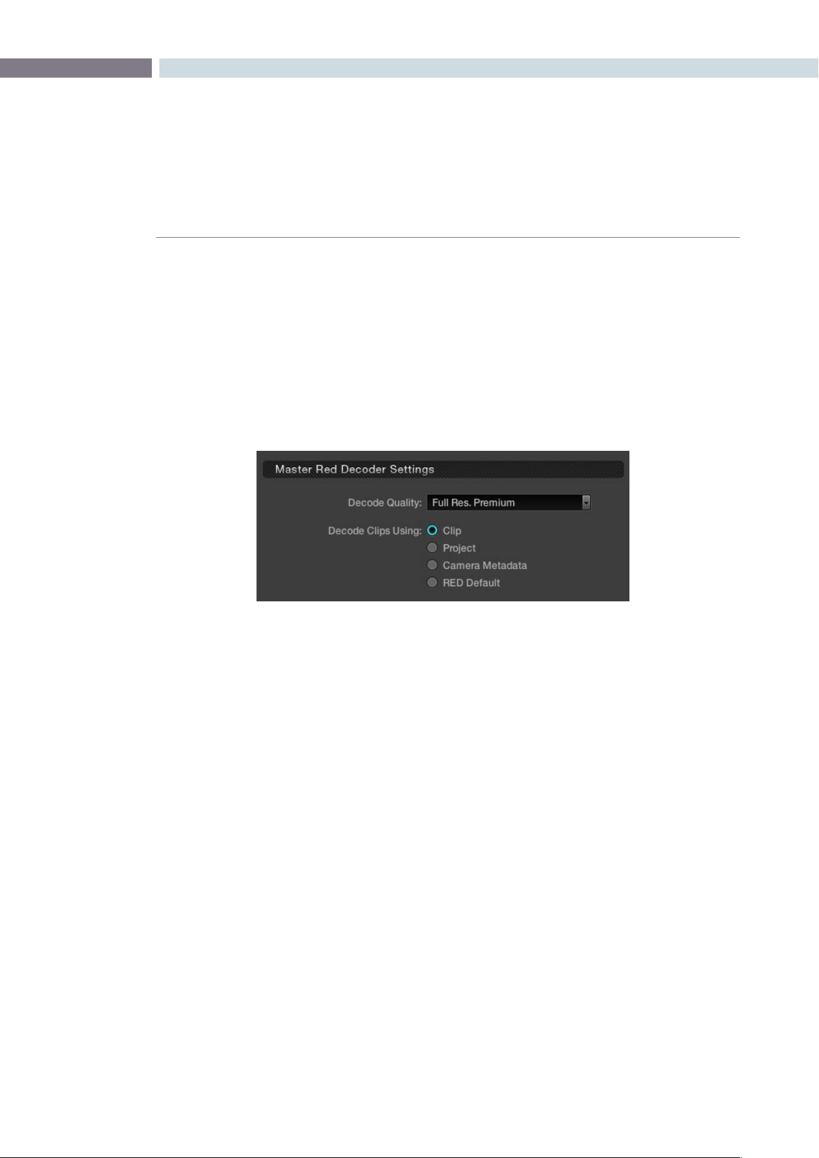
CHAPTER
COLOR
COLOR231
9
The second setting in this area is to select to source of the RED metadata for all the other decoder
settings.Ifyouleavethissettingon‘REDDefault’thenDaVinciResolvewillusethedecodesettings
suppliedfromRED.Ifyouselect‘CameraMetadata,’DaVinciResolvewillextractthecontrolling
metadatafromther3dleasitwassetbythecamera.The‘Project’settingwillusetheDaVinciResolve
configuration you set on the Source tab.
On the right of the window the Red Default, Camera Metadata, and Project settings for this clip are
displayedadjacenttotheslidercontrolsfortheClipsettings.The‘Clip’optionprovidesyouwith
signicantlygreatercontrolforeachclip.Selecting‘Clip’willmakealltheothercontrolsonthiswindow
active and you can set them as you prefer for this particular r3d clip.
Onceyouhaveselectedthe‘Clip’optionthereisalsoa‘Reset’buttonthatishighlightedatthebottomof
the window. If you make any changes to the clip decoder settings and you wish to revert to the settings
thatexistedwhenyourstopenedthewindow,usethe‘Reset’button.The‘Cancel’buttonwillclose
thewindowwithnochangesandthe‘Apply’buttonwillsavethechangesmadeandclosethewindow.
Master Red Decoder Settings - Clip Selection
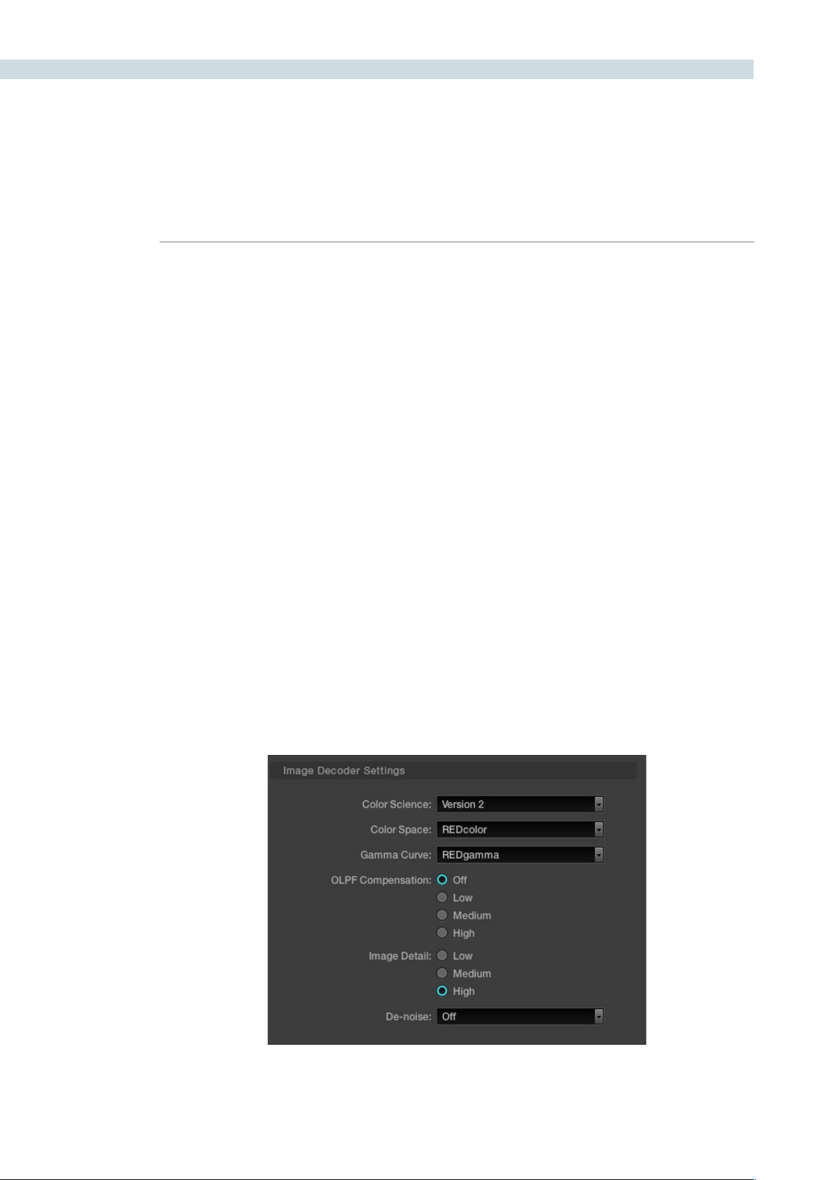
COLOR 232
Image Decoder Settings
Once you have selected the Clip option in the Master RED Decoder Settings, all parameters in the
Image Decoder become active.
Color Science: The original REDone camera builds used a different color science to the more
recent builds. Select here as appropriate.
Color Space: RED offers a number of different color space options when decoding the RAW
images: REDcolor, which is default color space; Camera RGB, which bypasses
the matrix in the camera and uses uncorrected sensor data; REDSpace, which
extracts a color space larger than REC.709, often used for film work; sRGB,
which is a color space used for monitors, printers and the Internet and REC.709,
which is the standard for HDTV.
Gamma Curve: The Gamma selections include: Linear, where no gamma adjustment is
applied; REC.709, which is the standard HDTV gamma; sRGB, which is a color
space used for monitors, printers and the Internet; REDSpace, which is a higher
contrast color space than REC.709; REDlog, which maps the native 12-bit RAW
image data into a standard 10-bit Log curve, and Custom PDLog, which offers
users an alternative LOG curve, similar to Cineon, and also provides for custom
adjustments as described below. The PDLog 685 and 985 offer alternative
white points for the Gamma Curve. The default is REDgamma.
OLPF Comp: The OLPF compensation sets a low-pass filter to reduce color moiré. There are
four options, with Off being the default.
Image Detail: Select from the low, medium, or high sensor detail extraction options.
Denoise: There are seven settings, from mild to maximum, to adjust for the best noise
reduction without image degradation.
Color screen Thumbnail Right Click to select Edit RED codec settings

CHAPTER
COLOR
COLOR233
9
Clip Decoder Settings
JustastheSourceTabontheCongscreenofferedProject-basedREDClipDecodersettings,this
window offers the same controls for each clip. You can easily compare the values of the clip settings
to the Project, Camera, or RED Default metadata as these are listed on the right-hand side of the
clip sliders.
ISO: Similar to exposure this control adjusts gain from the black point to white in a
linear manner. 320 is the default.
FLUT: The Floating Point Look-Up Table controls operate within the new color space
to give cleaner and finer ISO and mid-grey variation without introducing
clipping.
DRX: DRX is a dynamic range control that takes into account Color Temp (Degrees
Kelvin) and Tint.
Shadow: Provides adjustments at the toe of the FLUT.
Exposure: Calibrated to replicate industry standard f-stops, Exposure increases or
decreases the image lightness and clips the data levels at each end.
Brightness: This also adjusts the image brightness by changing the black level, but unlike
Exposure, this control will compress the image at each end of its range.
Contrast: With the mid-tones maintained, the Contrast control adjusts the number of
discreet steps in the grey scale by changing the slope of the response curve.
Color Temp: Sometimes referred to as Kelvin, the Color Temperature adjusts the RGB matrix
to consider the blue/red ratio. Common values are 3200 for Tungsten lighting
and 5600 for daylight.
Tint: Use the Tint control to adjust the yellow parameters of the RGB matrix. Ideal to
correct fluorescent or sodium vapor lamp problems.
Saturation: The color saturation is varied from monochrome at 0 value, to the default, or
unity, of 1, up to very over saturated at 5.
Custom PDLog: The Custom PDLog parameter, Black Point, White Point and Gamma are user-
adjustable from their respective default values of 95, 685 and 0.6 gamma.
Gain: The Red, Green and Blue Gain controls adjust each color channels gain with 0
being the reference point. One is unity gain and the maximum ten is ten times
greater amplitude than unity.
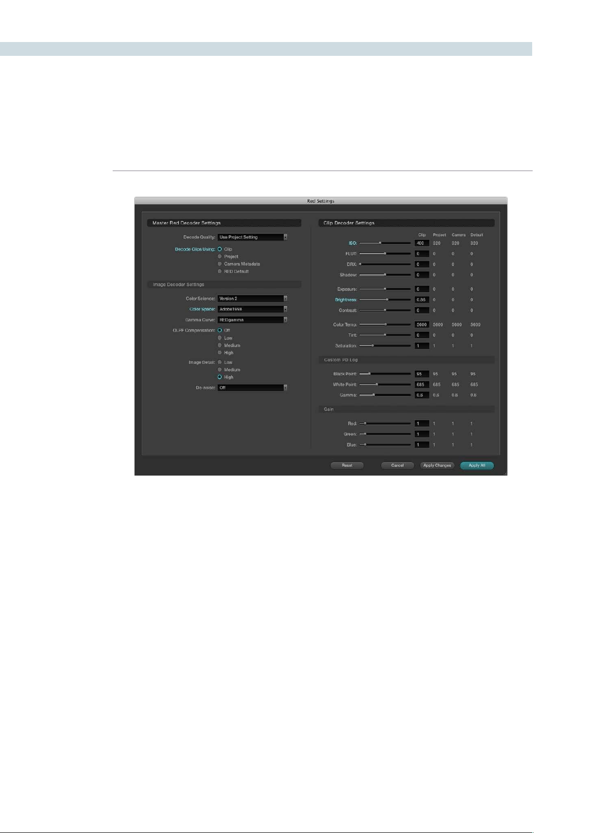
COLOR 234
RED clips can be ganged together and adjustments to the decode settings applied to all the ganged
clips. Simply select the clips in the Media Pool or Color screen timeline, select Edit Red Codec Settings.
Now adjust the decode parameters and watch the changes in real time. The decode parameter that you
adjust will now display its title in cyan rather than normal grey indicating that you have modified that
particularsetting.Youcanselect‘ApplyChanges’toapplyjustthechangeddecodeparameterstothe
selectedclips,or,‘ApplyAll’toapplyallthesettingstotheselectedclips,or,resettoreturnthesettings
to the status when you opened the window.
This new feature is ideal for making ISO or Gamma or Color Space changes to all the clips while
maintaining the camera metadata or project metadata settings for all the other parameters.
Color screen Thumbnail Right Click to select Edit RED codec settings
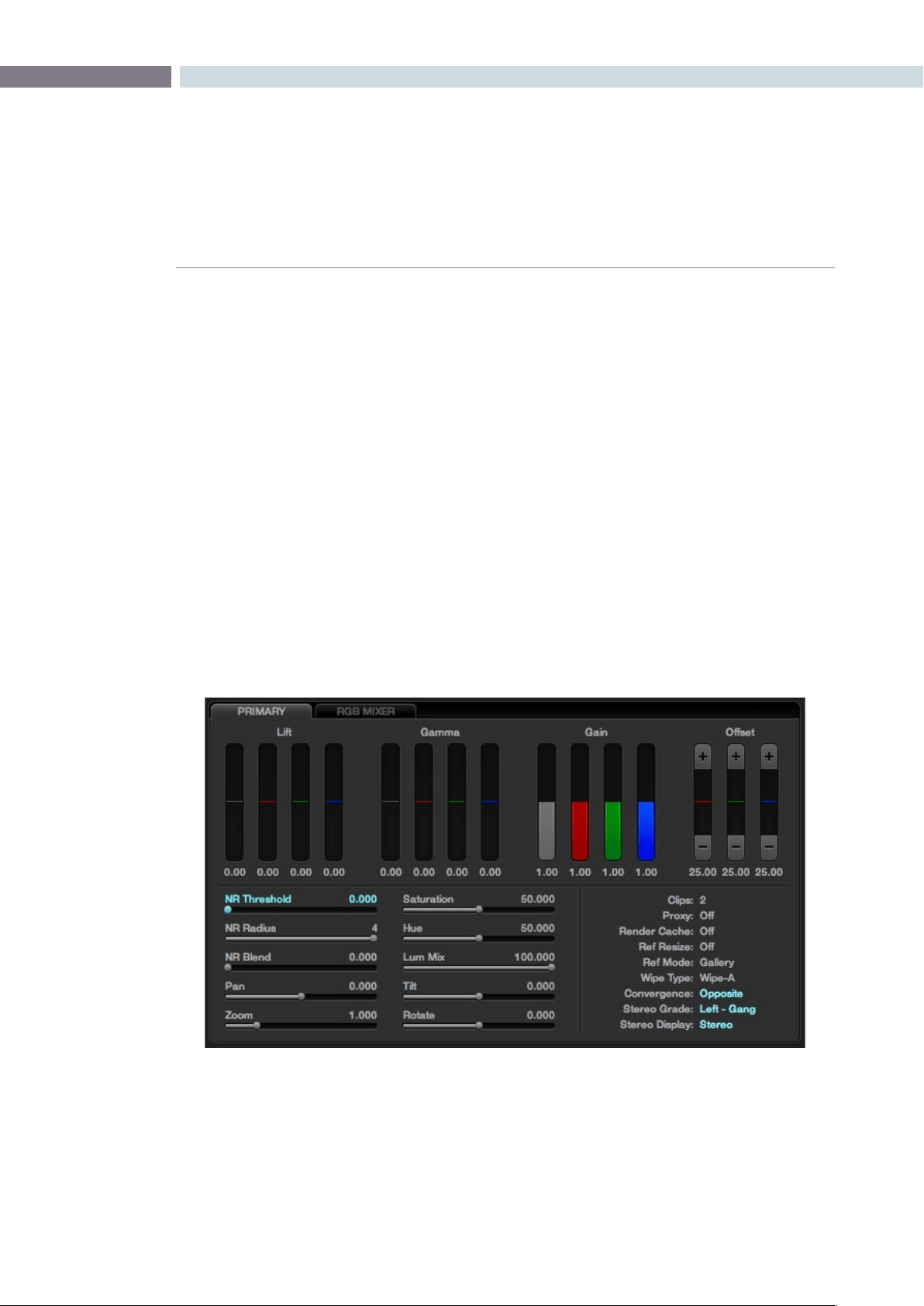
CHAPTER
COLOR
COLOR235
9
The Primary tab is located at the bottom left of the Color screen. This area displays the settings for the
Lift,GammaandGaincontrols,Offsets,SaturationandthePan,Tilt,ZoomandRotatecontrolsforeach
clip. There is also a status display providing a variety of system status indications.
A right mouse click within the Primary Color Correction tab will allow the user to reset all parameters
on this tab.
Primary Slider Controls
Typically, colorists use a control surface for grading as it permits multiple controls to be adjusted
simultaneously. No mouse, pen, or touch screen allows concurrent, simple and intuitive control of a
dozen parameters with just two hands.
For interactive feedback, these control panel adjustments are reflected in the interface of this Primary tab,
but you can also use your mouse to select any of the sliders or color bars to adjust individual parameters.
Generally, the first node in every scene is used to balance the primary values of the source clip and
subsequent nodes are used for effects, but this is, of course, a user preference. The Primary Color
Correction display will show the corrections that are being applied, using, from left to right, the Lift,
Gamma and Gain trackballs on the DaVinci Resolve trackball control panel.
Primary Tab
Primary Tab on the Color Page

COLOR 236
The trackball Lift, Gamma, and Gain controls are displayed as vertical colored bars with Red, Green and
Blue values for each. Adjacent to the colored bars is the Luminance value grey bar. These controls are
on the left of the panel trackballs, one each for Lift, Gamma, and Gain Luminance level.
On the right side of the right most trackball there are also three controls. The first pot adjusts the
Saturation of the isolated area, the second pot is a Hue control and the third pot adjusts the Luminance
mix control. Each of these controls mirror the horizontal sliders on the Primary tab. You can select them
with your mouse and adjust or reset any control with a mouse click on the value adjacent to the slider.
To the right of the Color Level displays are the Offset controls and display. You can grade material by
using printer light steps using the offset up and down buttons.
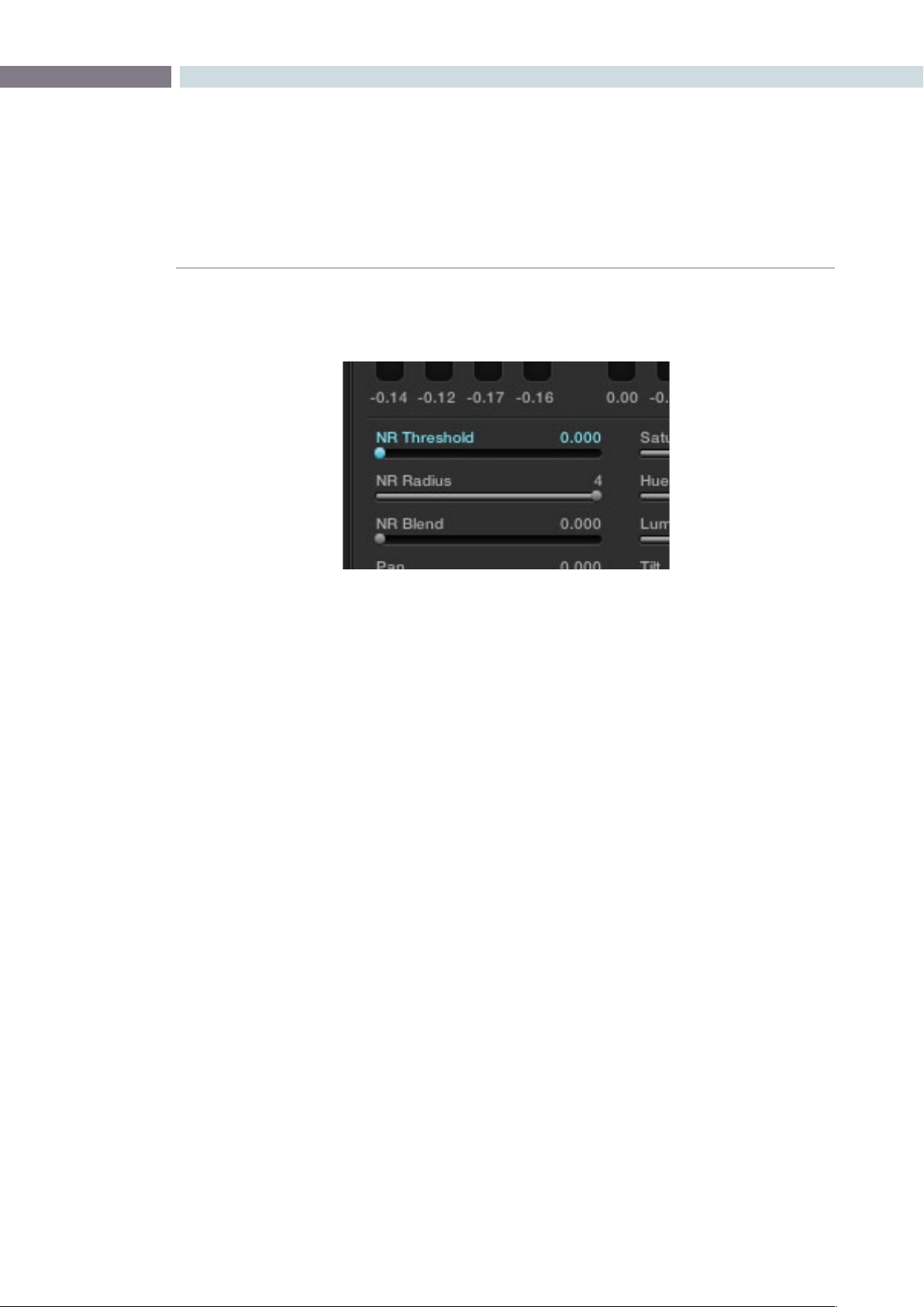
CHAPTER
COLOR
COLOR237
9
DaVinci resolve has GPU-based noise reduction that’s designed to let you quickly and easily subdue
noise in problematic clips, in real time.
Three parameters, located within the Primary tab of the Color page, control this effect:
NR Threshold: Lets you determine how much or how little noise reduction to apply to the
image by smoothing out regions of high-frequency noise while attempting to
preserve the sharpness of significant edge details. The range is 0-30, where 0
applies no noise reduction at all, and 30 is the maximum amount. Too high a
setting may soften the overall image too noticeably.
NR Radius: Higher values enable greater real time performance, and provide good quality
when using low NR Threshold values. However, you may see more aliasing in
regions of detail when using high NR Threshold values.
Setting NR Radius to progressively lower values results in higher quality within
areas of greater visual detail at high NR Threshold values, at the expense of
slower performance. The range is 1-4 (in whole integer values), where 4 is the
highest performance and lowest quality, and 1 is the highest quality and lowest
performance. An NR Radius of 3 should provide suitable quality for most
images when using medium NR Threshold settings.
NR Blend: Lets you dissolve between the image as it’s being affected by the NR
parameters (at 0.000) and the image with no noise reduction at all (1.000).
This parameter lets you easily split the difference between aggressive noise
reduction, and the prior state of the image.
As you can see, there’s an adjustable tradeoff between quality and speed.
Noise Reduction
Noise reduction controls in the Primary tab of the Color page
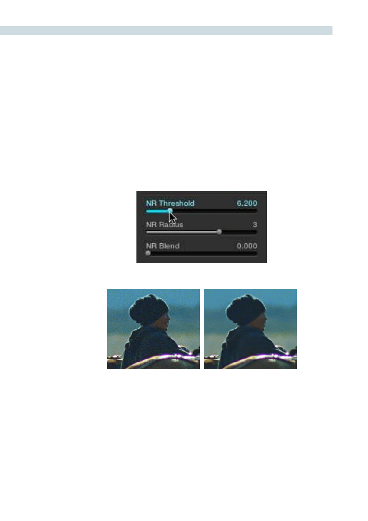
COLOR 238
Using Noise Reduction
The following procedure suggests a method of using the noise reduction (NR) parameters to achieve
a controlled result.
Applying noise reduction to an image:
1. Move the NR Threshold slider to the right until you strike a suitable balance between
the reduction of noise, and an unwanted increase in image softness.
As you make this adjustment, the image updates in real time.
2. If you’ve had to use a high NR Threshold setting to visibly reduce noise, and areas of
detail look a bit chunky or aliased, you can reduce the NR Radius parameter to enable
a more detailed analysis of the scene.
This will result in higher visual quality, but lower NR Radius settings are more processor
intensive, and may reduce real-time performance if you don’t have adequate GPU
resources available to your system.
3. If you’ve found suitable noise reduction settings, but the result is too aggressive and
makes the image appear too processed, you can try raising the NR Blend slider to
fade between the noise reduced result and the previous state of the image without
noise reduction.
Left–the original image, Right–the image with noise reduction applied

CHAPTER
COLOR
COLOR239
9
NR Radius, How Low Should You Go?
Lower NR Radius settings can dramatically improve the quality of high detail regions in shots
where you’re using aggressive noise reduction, but it’s not necessary to always jump to the
lowest value that provides the highest precision. In many cases, when evaluating an image
that you’re applying noise reduction to, you may not actually be able to perceive the additional
quality, and you’ll waste processing time on an unnecessary level of correction.
It’s a good idea to make sure that you’re evaluating the full-frame image on a large enough
display to see the noise you’re working on within the viewing context of the intended audience.
Zoomingreallyfarintoaclipwhileapplyingnoisereductionmayencourageyoutousehigher
quality settings then are necessary, because an excessively enlarged detail of an image lets
you see subtle changes that you wouldn’t notice at actual size.
Limiting Noise Reduction
As with any other correction in the Color page, noise reduction can be limited using HSL Qualification
or Power Windows. This means you can focus your efforts on reducing noise in the most problematic
areas of an image (for example, in shadows and background regions), while sparing elements that you
don’t want to affect (such as faces or better-lit areas of the image).
Furthermore, you can use noise reduction in lieu of the Blur settings to perform a subtler form of
complexion smoothing, using the HSL Qualifier to key an actor’s skin tone for targeted noise reduction.
Controlling the Order of Operations for Noise Reduction
You can apply noise reduction at any point in your image processing tree using a dedicated node. If you
have an image with noise that you think might be enhanced by whatever corrections you need to make,
for example increasing the contrast of underexposed clips often increases whatever noise is within an
image, there are two approaches to noise reduction:
Apply noise reduction at the beginning of a node tree:
This lets you preemptively eliminate any noise before it becomes a problem as
a result of whatever adjustments you’re planning on making. The end result can
be smoother, but you may also notice that the edge detail within the image is
a bit softer as a result.
Apply noise reduction at the end of a node tree:
The alternative is to make your adjustments first, and then apply noise reduction
in a separate node afterwards. In this case, you may find that the noise reduced
regions of the image aren’t quite as smooth, however the edge detail within the
image may be visibly sharper as a result.
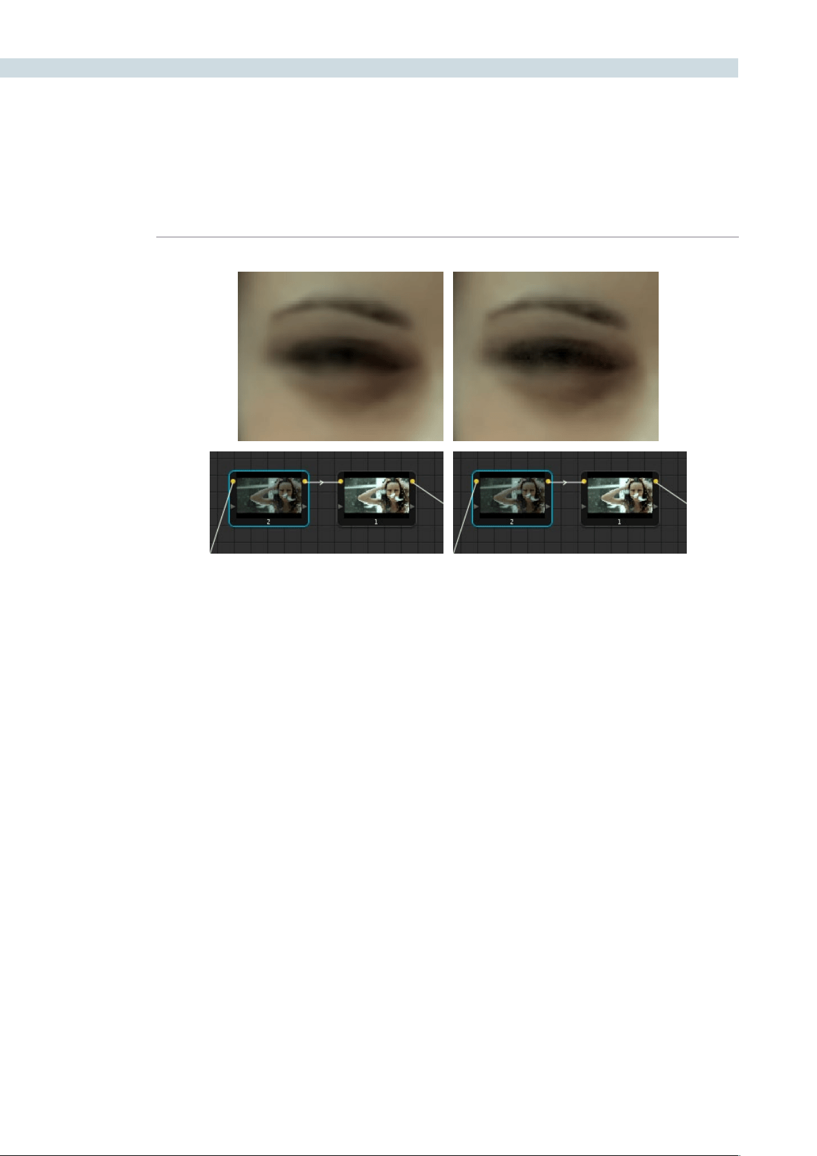
COLOR 240
Neither result is universally better or worse then the other. Which is preferable depends on the image
you’re working on, and the type of result you’re looking for. You might prefer some shots to be a bit
softer, while you’d like other shots to be a bit sharper. The real point is that the node-based image
processing of DaVinci Resolve lets you choose which technique works best for you.
Note: If you apply noise reduction and make color adjustments within the same node, noise reduction
is processed first, followed by color adjustments.
Using Noise Reduction Controls with the DaVinci Resolve
Control Surface
All three noise reduction controls are available via rotary knobs on the PRIMARIES, NOISE REDUCTION
control group on the center panel.
To open the noise reduction controls on the DaVinci Resolve control surface:
Press the PRIMARIES or MAIN display button on the center panel, whichever is
visible depending on which control group is currently displayed.
Left, the image with NR (node 2) applied prior to contrast expansion (node 1); Right, the image with NR
(node 2) applied afterwards; Noise is reduced in both instances, but detail is handled differently

CHAPTER
COLOR
COLOR241
9
Input Sizing Controls
DaVinci Resolve has an optical-quality image resizing engine that can be used to position or resize
images with such high precision that you can resize the image using dynamics and see the changes in
real time.
AtthebottomleftofthePrimarytab,theInputsizingcontrols,Pan,Tilt,ZoomandRotate,mirrorthose
found on the Control Panel.
Primary Tab System Status
On the right side of the Primary tab there is a system status display showing the operational status of
DaVinci Resolve.
Clips: The number of clips in the timeline will be displayed.
Proxy:Ifthe‘OntheFlyProxy’modeisselected,orproxiesareenabledonthe
Config screen, this indication will be On.
Render Cache: There are five modes to toggle for render cache: Off, do not perform any
cache; Cache All to cache all clips; Cache D to cache all dissolves; Cache
User to cache individual clips marked by you for caching, ; and Cache + to
cache dissolves plus user-selected clips.
Ref Resize: When On, the reference clips can be resized and repositioned.
Ref Mode: The reference for grading can be the Gallery stills, any clip on the Timeline
or the Offline clip.
Wipe Type: The available wipe modes are Horizontal, Vertical, Mix, and Key.
Convergence: In Stereoscopic 3D operation, when you adjust the convergence of the
two eyes there are two modes: Opposite, where the convergence control
moves each eye away or towards each other, and Linked Zoom, where
there is insufficient image to fill the screen due to the convergence
adjustment and the images will automatically zoom to fill the screen.
Stereo Grade: Resolve 3D projects can be graded in Solo mode when only one eye is
adjusted by the grade or Gang mode when both eyes are graded together.
The active eye is also indicated here.
Stereo Display: The display output can be a single eye, i.e. Mono or both eyes, Stereo,
as required.
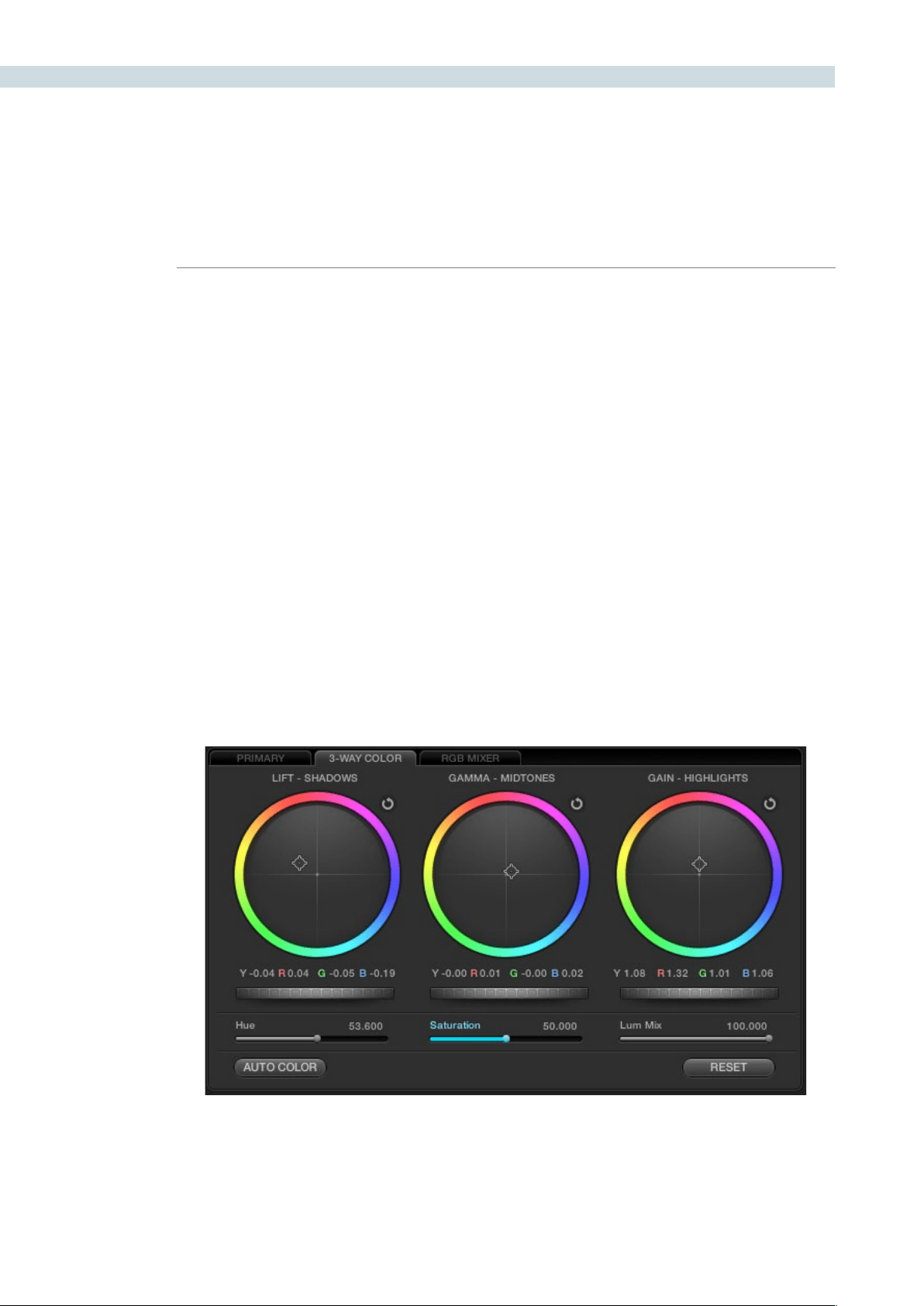
COLOR 242
3-Way Color Corrector
Control of the RGB balance of the grade in the shadows, midtones and highlights of an image can be
made with the 3-Way Color tab. The 3-Way Color controls provide an easy way to adjust and balance
the RGB values with a mouse, trackpad or pen and tablet. Values for the controls are reflected in the
alternate tab view and you can switch between the Primary and 3-Way Color tabs as needed.
Color Wheels
At the top half of the tab you will see three colored wheels each with an internal cursor indicating the
current RGB grade for the respective shadows, midtones and highlights of the image.
The adjustments you make in the Lift, Gamma and Gain wheels change the mix of the red, green and
blue channels and adjusting the grades in wheel will influence the whole image so it’s common to make
small trim adjustments in each wheel to get a final primary grade.
If you left click and hold within the Lift-Shadows colored wheel and move your mouse toward the yellow
edge, as shown in the image below, the darker elements of the image will take on a yellow influence.
Move the mouse towards the red edge and the image becomes redder in the darker areas. The more
you move the cursor towards the edge of the wheel the greater the influence. You can at any time
release the mouse and move it to another part of the wheel and click again and drag to extend the
movement in any direction.
To quickly move the grade towards a color, Shift-click inside the color wheel near to the grade you are
targeting. Then release the shift key to fine tune the grade.
Underneath the three wheels the Y, R, G and B numerical values of the grade are displayed and these
track the movements of the wheel cursors. They also match the YRGB values found on the Primary tab.
3-Way Color Tab

CHAPTER
COLOR
COLOR243
9
Master Scroll Wheel
Directly under these numerical indications are the master scroll wheels. As you click and drag each
control to the left or right you will decrease or increase the master level. Note that the Y, R, G and B all
move together. You can also use the scroll wheel or the two finger gesture control to use this control
instead of holding down the left button of the mouse. Holding the Option key, and adjusting this control
lets you control the Lum (Y) individually.
The master levels and luminance levels are also adjustable using the Command key and Option key
respectively and scrubbing the mouse or pen horizontally in the respective color wheels.
If you review the image waveform you can quickly see how the Lift master control can bring the image
shadows closer to or further away from 0 IRE or black. The Gain master will move the image towards
the white point and the Gamma master will influence the image between the blacks and whites.
Resets
Each of the parameters you adjust in the 3-Way Color wheels has resets. Use the reset icon at the top
right of each wheel to reset that wheel.
DoubleclickinginsidethewheelwillresettheRGBvaluesbutnotthemastercontrol.JustastheOption
scroll wheel adjusts the Luminance only, holding the Option key and selecting the wheel reset will reset
that Luminance value.
Resolve also has a level reset operation. Use the Command key and click lift, gamma or gain reset to
adjust the YRGB levels around the default values while maintaining the balance between these values.
At the bottom right of the tab there is also a tab reset for all parameters.
Hue, Saturation and Lum Mix
The three sliders below the scroll wheels are the Hue, Saturation and Lum mix controls. These mirror
the physical controls on the right side of the DaVinci Resolve Control Surface and the sliders on the
Primary tab.
You can select them with your mouse and adjust or reset any control with a mouse click on the slider
name. To change the overall saturation or hue of the image or within a qualified area simply adjust the
slider. To type in a precise number, it is possible to click on the number on any of the sliders and type
in a value.
The Lum Mix control provides a balance between the DaVinci YRGB grading parameters that are native
in Resolve and the Y extracted from the traditional RGB in a 3-Way color grading system.
Auto Color
The Auto Color button provides a quick way to balance the blacks and whites of the image. Resolve
looks for the darkest levels to balance the RGB in the blacks and the brightest to balance the RGB in
the highlights for the Auto Color grade.
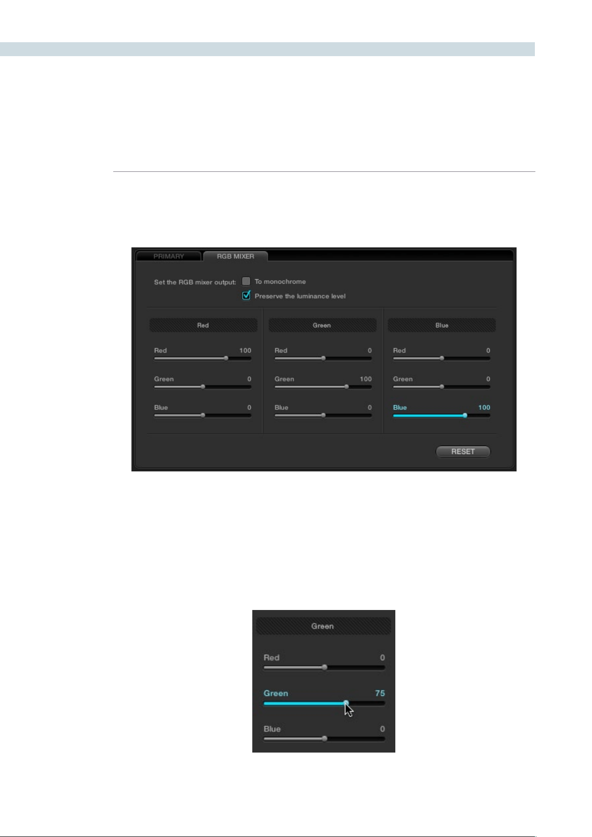
COLOR 244
RGB Mixer Tab
The RGB Mixer lets you remix different amounts of image data from one channel to another, to
accommodate a wide variety of creative and utilitarian uses. Furthermore, the RGB Mixer can be used
to remix the color channels, or used to mix the color channels into a monochrome image.
By default, the RGB Mixer is set to mix any amount of the red, green, and blue color channels into any
of the other channels. Each Color channel has a dedicated control group of Red, Green, and Blue sliders
that you use to do the mixing, and the default values of these
Eachsliderhasanoverallrangeof-200to+200.Thismeansthatyoualsohavetheoptionofsubtracting
any combination of color channel values from a particular channel. For example, you can lower the Red
control group’s Green slider to -24 to subtract 24 percent of the green channel from the red channel.
The RGB Mixer, next to the Primary tab
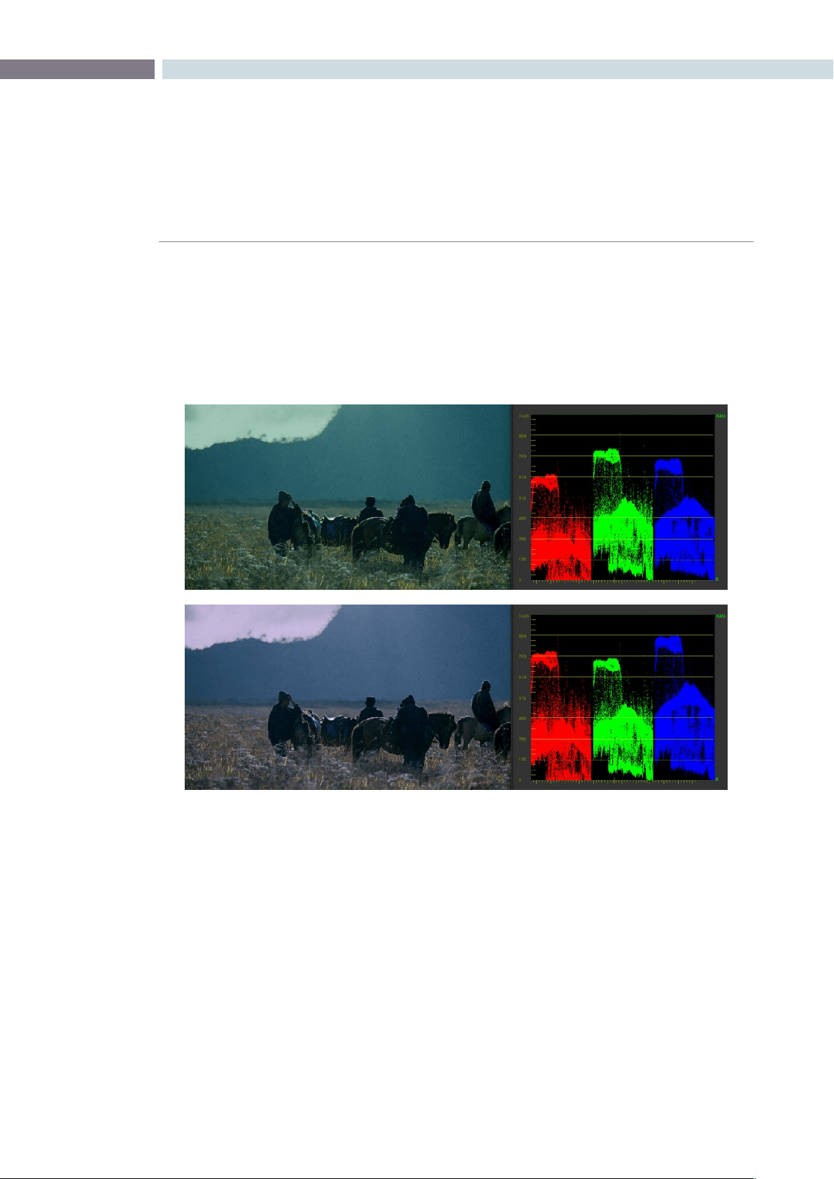
CHAPTER
COLOR
COLOR245
9
The “With luminance level preserved” checkbox, which is on by default, keeps any channel adjustment
you make from altering the luma of the image by automatically raising or lowering the other two
channels to compensate. In the following example, you can see when “With luminance level preserved”
turned on, lowering the Green control group’s Green slider results in the red and blue channels being
raised by the same amount as seen in the Parade scope. Conversely, raising a color channel’s slider ends
up lowering the other two channels by the same amount to keep overall image luminosity the same.
If you Right-click anywhere within the RGB Mixer while in Color mode, a shortcut menu appears with
four commands:
Reset: Resets all sliders to their default positions (Red = 100 for red, Green = 100
for green, Blue = 100 for blue, and all other sliders = 0).
Swap Red and Green: Swaps these two color channels.
Swap Green and Blue: Swaps these two color channels.
Swap Red and Blue: Swaps these two color channels.
At top, the original image. At bottom, the result of an RGB Mixer adjustment with “With luminance level preserved”
turned on. You can see that lowering the green channel slider also raises red and blue.
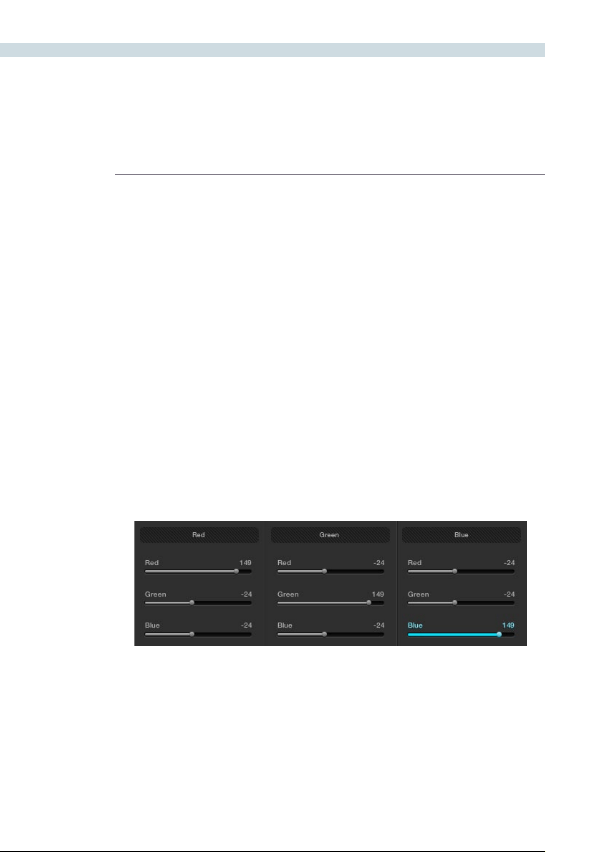
COLOR 246
RGB Mixer Examples
This is an extremely flexible and open-ended tool, and you’re probably already getting a sense of the
creative possibilities. However, here are a couple of more utilitarian uses of the RGB mixer that are a bit
less obvious.
Example 1: Increasing Saturation While Reducing Cross-Talk
In this first example, we’ll see a creative use of the RGB Mixer that uses a technique similar to one used
by telecine artists, to “purify” individual color channels, and raise image saturation in a different way then
when using the Saturation parameter.
To raise saturation while eliminating color channel crosstalk:
1. To isolate this correction from the other operations in your node tree, create a new
serial node.
2. Open the RGB Mixer tab in the Color page.
3. In each of the three control groups (Red, Green, and Blue), boost the value of the
primary color parameter for that group, while reducing the value of the other two color
parameters by half.
For example, in the Red control group, raise the Red parameter to 148, while lowering
the Green and Blue parameters to -24 each. Do the same for the Green control group,
raising Green while lowering Red and Blue, and the Blue control group, raising Blue
while lowering Red and Green.
RGB Mixer settings used to boost saturation and reduce color channel crosstalk
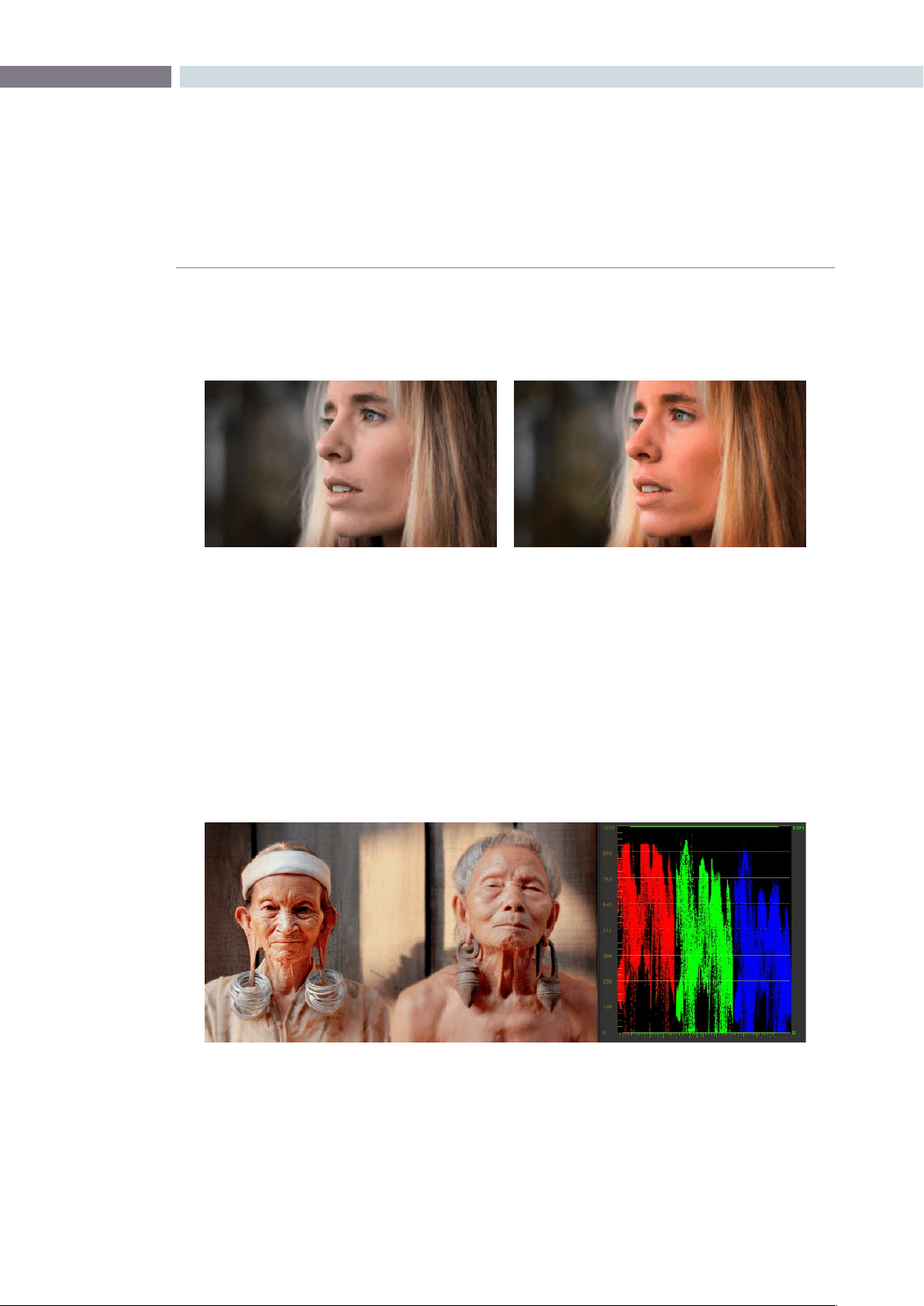
CHAPTER
COLOR
COLOR247
9
The result will be a visible boost in image saturation, but in a subtly different way then
were you to simply raise the Saturation parameter. Experiment with different images to
see how this works.
Note:Thetotalvalueof48that’susedtoaddto(+48)andsubtractfrom(-24,-24)eachcolorchannel
combination is arbitrary, the important thing is to balance the amount you’re adding with the two half-
values you’re subtracting.
Example 2: Patching Clipped Color Channels
In this second example, you’ll see how you can limit the effects of the RGB Mixer to selectively “patch”
portions of an image with unwanted clipping in one of the color channels. In the following image, the
red channel of the highlights was clipped during the shoot, and the subsequent rebalancing of the
highlights has only lowered the flattened top of the red channel as seen in the RGB Parade scope to the
right of the image. The result is a subtly harsh, flat region that is unflattering.
The original image on the left, and the altered version on the right.
At top, the original image. At bottom, the result of an RGB Mixer adjustment with “With luminance level preserved”
turned on. You can see that lowering the green channel slider also raises red and blue.
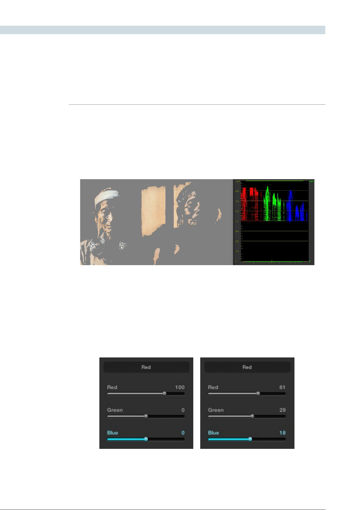
COLOR 248
We’ll see how you can attempt to correct this sort of issue using the RGB Mixer.
To patch blown-out channels with sections of other channels:
1. First, identify the region of the image with clipped out highlights or shadows that
you want to try to fix, then add a node and isolate the clipped region using HSL
Qualification. You can either key a range of color, or luma only using the controls of the
Luma tab.
This technique only works for images where a single color channel is clipped, but image detail
exists in the other two.
2. Open the RGB Mixer tab, and use the control group corresponding to the clipped color
channel to add image data from the other two channels.
For example, if the red channel is clipped, use the parameters in the Red control group
to raise the Green and Blue parameters in whatever proportion works to add a bit of
detail back to the clipped area of the red channel. It can be easier to see what you’re
doing if you check an RGB Parade scope’s analysis of the image.
Left–the original Red channel mix; Right–mixing parts of the green and blue
channels into the red channel, with less red
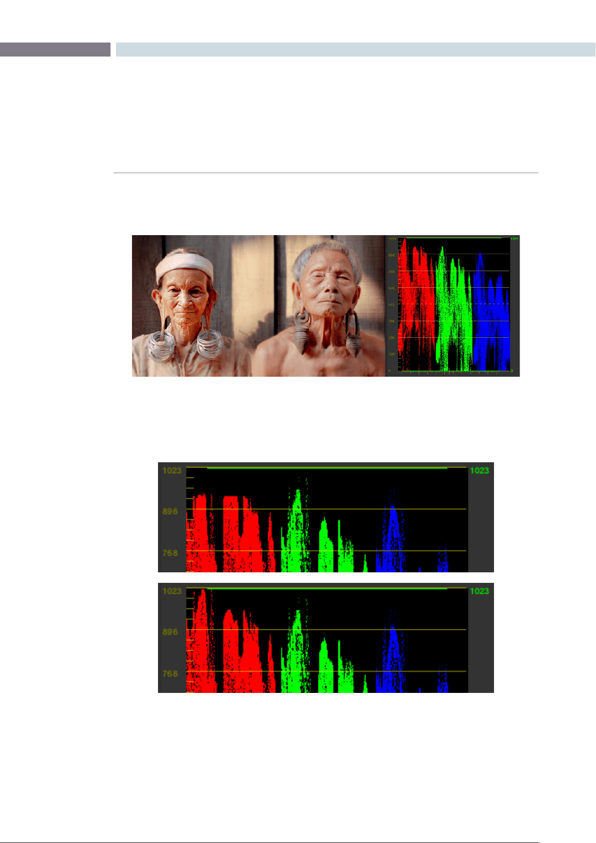
CHAPTER
COLOR
COLOR249
9
You should see some nice pixel detail reappear in formerly “flat” areas of the image,
although the color channel you’re correcting may become exaggerated as a result.
If necessary, you might need to alter the color balance of the highlights or shadows,
whichever was clipped to achieve a more realistic coloration within the patched region.
The result can be better seen by comparing the RGB Parade scopes before and after
this adjustment.
When you’re done, you should see a bit more pixel detail in the formerly clipped
regions of the image, with more pleasing color rendition.
Top–the original clipped red channel; Bottom–the “patched” red channel
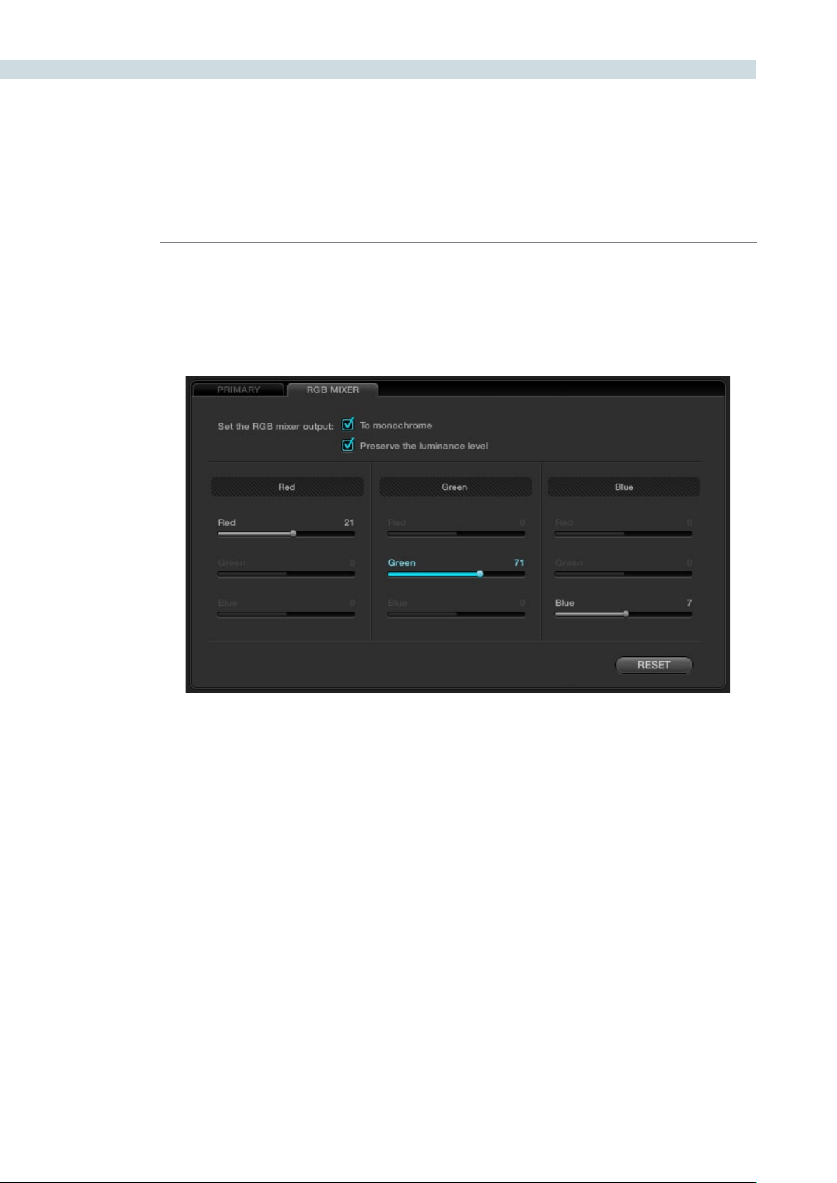
COLOR 250
Using the RGB Mixer in Monochrome Mode
When you turn on the “To monochrome” checkbox, a pair of parameters within each slider group are
disabled so that the only available controls are the Red > Red slider, the Green > Green slider, and the
Blue > Blue slider.
Keeping in mind that each of the color channels that makes up an image is itself a grayscale channel,
the sliders, in Monochrome mode let you add different proportions of the red, green, and blue color
channels together to create custom grayscale versions of a shot.
To understand why this is useful, let’s consider the default values of the Red, Green, and Blue sliders. To
emulate the human eye’s sensitivity to the wavelengths of light, the Rec 709 video standard defines an
isolated Luma (Y’) component as consisting of 0.2126 of the red channel, 0.7152 of the green channel,
and 0.0722 of the blue channels added together. This can be seen in the default values, rounded to the
nearest integer percentage of 21, 71, and 7.
This is the standard method of deriving a black and white version of a color image, and in fact produces
identical results to those obtained by setting the Saturation parameter to 0.
However, there have traditionally been other ways of mixing the colors of life into different grayscale
interpretations. For example, photographers often use colored filters in conjunction with black & white
film stocks, such as a yellow/green filter to emphasize pleasing skin tone for lightly complexioned
people. A much older example is the use of black & white film stocks with different sensitivities. Old
orthochromatic stocks were not sensitive to red wavelengths, recording only blue and green to create
an image.
Sliders at their default values when “To monochrome” is enabled
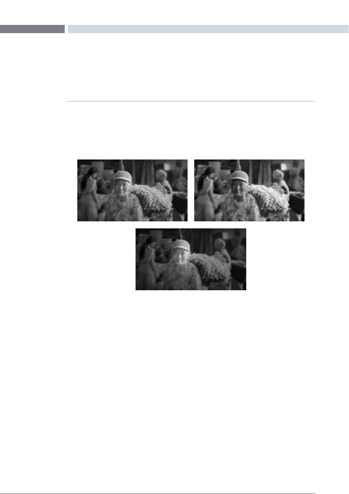
CHAPTER
COLOR
COLOR251
9
Using the RGB Mixer with “To monochrome” turned on gives you the ability to mix your own
custom blends of all three color channels to emphasize the creative characteristics you require.
For instance, increasing the mix of blue and decreasing red and green can give skin tones a darker,
metallic sheen. The following screenshots show multiple versions of the same image with different
monochrome mixes.
Like the parameters in Color mode, you can use the RGB Mixer’s “To monochrome” mode to subtract
one color channel from the others, for even more creative effects.
Two methods of resetting slider values in monochrome mode:
•Double-clickanyslider’snumericvaluetoresetthatsliderto0.
•Right-clickanywherewithintheRGBMixertabandchooseResetfromthemenuto
set the sliders to their default 21, 71, 7 values.
Using the RGB Mixer Controls with the DaVinci Resolve
Control Surface
All of the RGB Mixer controls are available from the DaVinci Resolve Control Surface.
To open the RGB Mixer controls on the DaVinci Resolve control surface:
•PresstheCURVESdisplaybuttononthecenterpanel.
Three monochrome mixes of the same image

COLOR 252
To exit the RGB Mixer curve controls:
•PresstheMAINdisplaybuttononthecenterpanel.
To adjust the principle color regions using knobs:
•Adjustoneofthefourgroupsofrotaryknobs.Allarelabeledtoidentifywhich
RED/GREEN/BLUE source channels are paired with RED/GREEN/BLUE destination
channels. For example GREEN->BLUE adds or subtracts an amount of the green color
channel from the blue color channel.
•PressthePRESERVELUMdisplaybuttontoturnonthe“Withluminancelevel
preserved” checkbox.
•PressMONOtoturnonthe“Tomonochrome”checkbox.
•PressCOLORtoturnoffthe“Tomonochrome”checkbox.
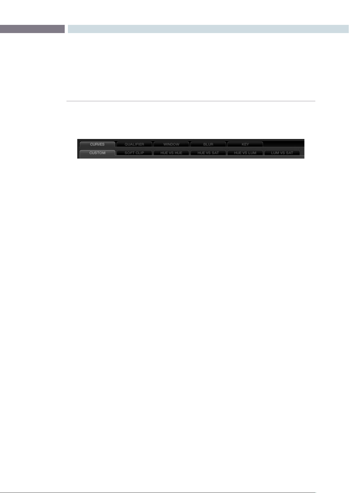
CHAPTER
COLOR
COLOR253
9
Curves Tab
The Curves tab, at the bottom center of the Color page, has six sub-tabs that provide different, curve-
based methods of manipulating the color and contrast of an image.
Each curve lets you adjust a customizable region of the image based on image tonality to make
adjustments relative to an area of brightness within the image, or on hue to make adjustments relative
to the specific colors within the image. All curves can be adjusted either using the mouse, or via knobs
on your control surface.
Tip: All curves in DaVinci Resolve can be used either to affect the overall image, or limited to affect only
a specific portion of the image as a secondary operation using HSL Qualification, Windows, imported
Mattes, or any combination of these.
Adjusting Curves Using the Mouse
All curves have identical controls for basic on-screen adjustment using the mouse.
Methods of adjusting curves using the on-screen interface:
To add a control point:
Click anywhere on or around a curve. A control point is added
at the position of the mouse where you clicked, and the curve is
altered, if necessary, to match the new control point’s position.
To add a control point without altering the curve:
Hold the Shift key down, and click anywhere on or around a
curve. A control point is added at the horizontal position of the
pointer where you clicked, but the curve is not altered.
To remove a control point: Right-click any control point to make it disappear.
To reset a curve to a completely neutral setting:
Click Reset.
To reset all Custom curves: Right-click anywhere within the Curves tab and outside of each
curve control box and choose Reset Custom Curve.
By default, individual control points influence the portion of each curve that falls between its neighboring
two control points.
In screenshot to the left, you can see that the control point at the position of the pointer is affecting the
larger part of the curve that falls between the lower left-hand control point, which is there by default,
and a user-created control point placed up within the highlights of the curve.
All the sub-tabs found within the Curves tab
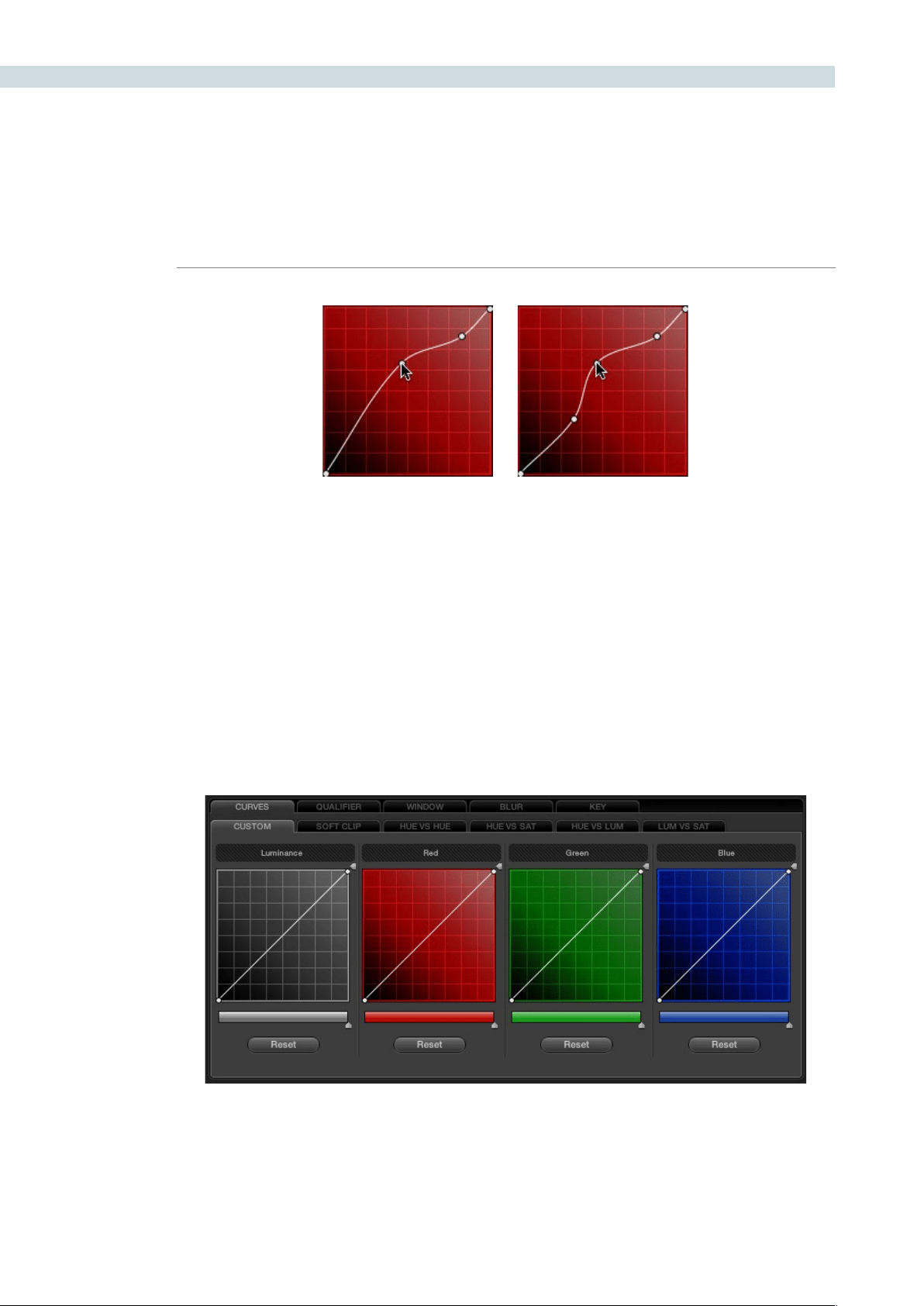
COLOR 254
In the screenshot to the right, an additional control point to the left of the one being adjusted limits
the area of the curve that is adjusted. By careful placement of additional control points, you can make
extremely targeted adjustments to images using the Custom curves.
This example highlights the importance of using control points to “lock off” portions of a curve at a
neutral or nearly neutral position to prevent changes to specific portions of an image, even while using
other control points to make changes.
Note: The HUE VS HUE/SAT/LUM and LUM VS SAT curves also have an optional adjustment mode
using Bezier curves that will be covered in those sections.
About Custom Curves
DaVinci’s Custom curves provide smooth adjustment of each clip’s Y, R, G, and B channels.
The YRGB Custom curves are useful for making more specific adjustments to an image then can be
accomplished using the color balance controls. They’re also useful for making strange and wonderful
stylistic adjustments through unusual alterations to different combinations of color channels.
Control point adjustments affect the entire portion of a curve between the next two adjacent control points.
The Luminance, Red, Green, and Blue (YRGB) Custom curves at their neutral defaults
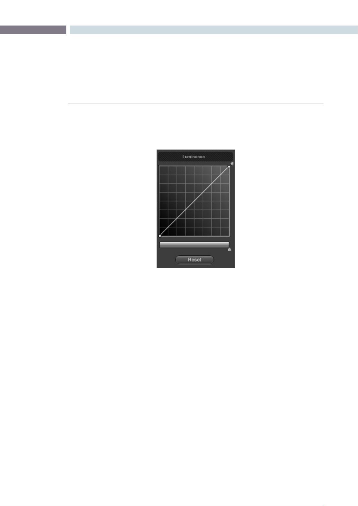
CHAPTER
COLOR
COLOR255
9
Each curve control box is square. The default, neutral position of a curve is a diagonal line that runs
from the black point of the image at the lower-left corner, to the white point of the image at the upper
right corner.
The horizontal axis represents the range of image tonality in the original image, while the vertical axis
represents the range of alteration you can make. By adding control points to the surface of the curve
and raising or lowering different areas, you are actually remapping the horizontal “input” tonality of a
color channel to an “output” value of your choosing.
Tip: The background grid makes it easy to see which parts of any curve are at or near the diagonal
default that represents no change made.
Ganging and Unganging Custom Curves
By default, the Custom curves are ganged, meaning that changes made to one curve are automatically
made to all the other curves.
Controls attached to each Custom curve; the handle on the upper-right hand side is the
YSFX vertical slider, and the slider underneath is the Curve Mix slider
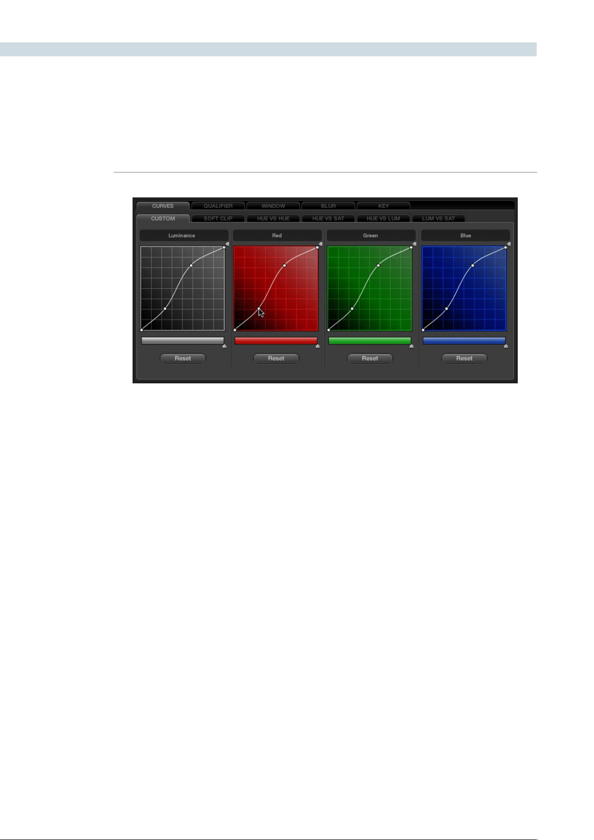
COLOR 256
When ganged together, curve adjustments affect a clip’s RGB luma levels identically to using a control
surface’s wheel controls. Making this type of adjustment to increase luma contrast also increases image
saturation, and since curves can be manipulated with greater specificity then the three contrast wheels,
you can make much finer adjustments.
To enable or disable Custom Curve ganging:
•Right-clickanywherewithintheCustomtab,butoutsideofthecurveadjustment
boxes, and choose Gang Custom Curves from the resulting menu.
Turning ganging off lets you use the full power of Custom curves to alter the image. Unlike the color
balance controls as used with a control surface, which are typically used to adjust all three color channels
simultaneously, the curve controls let you adjust each channel individually when Gang Custom Curves
is turned off.
Tip: When curve ganging is disabled, the Luma curve allows you to adjust the Y channel only, similar
to using the three Y’-only knobs of a control surface. When making this type of adjustment, increasing
luma contrast results in a perceptual decrease of image saturation.
Copying Color Channel Curves
Even if you’ve unganged the Custom curves, you can still mirror one curve’s adjustments to another by
copying it.
To copy a Custom curve from one channel to another:
•Option-dragtheCurveyouwanttocopyontothecurveyouwanttopasteto.
The pointer appears with a plus sign underneath to indicate that you’re successfully
dragging one curve onto another.
When Custom curve ganging is enabled, changes to one curve are applied to all curves
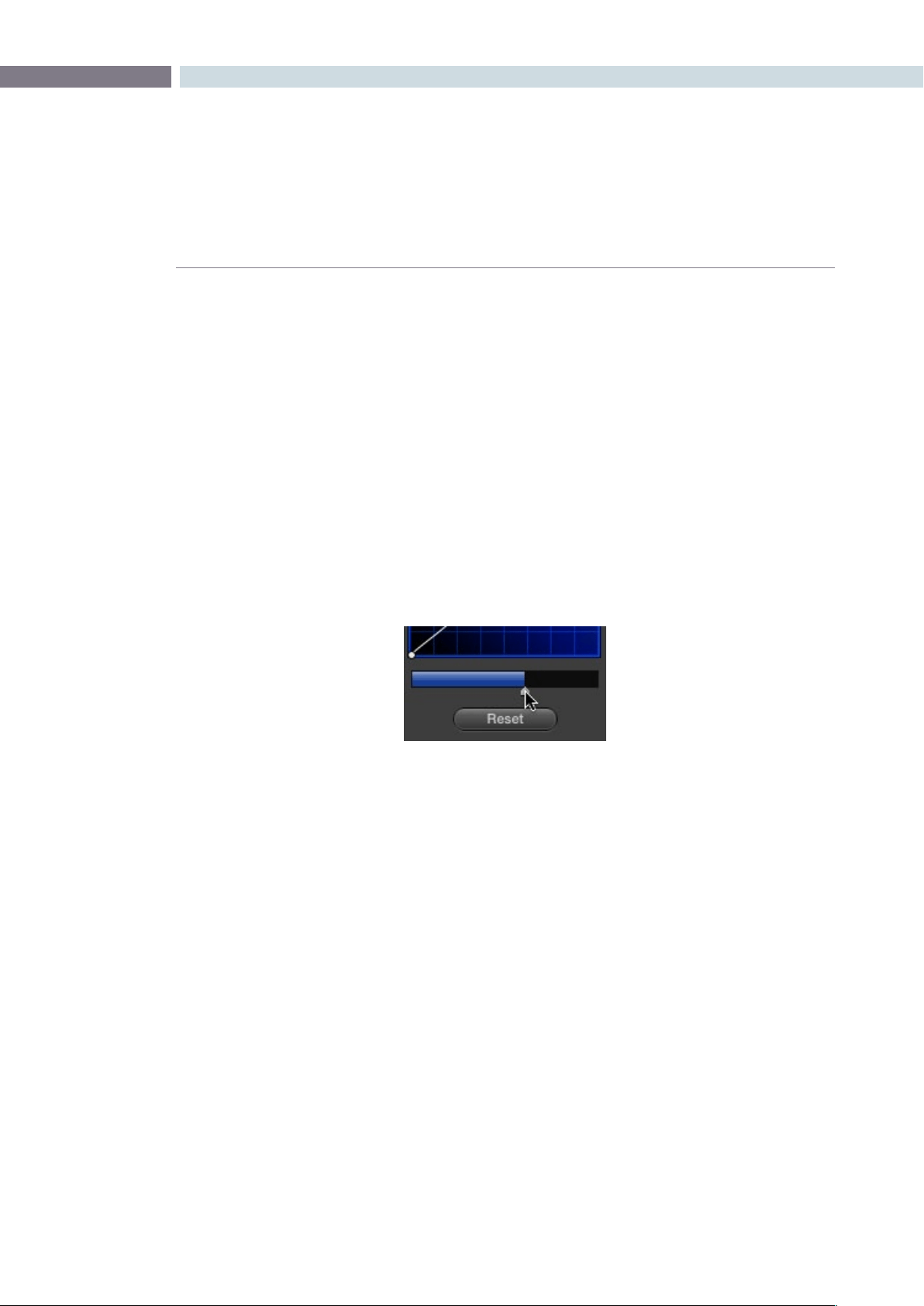
CHAPTER
COLOR
COLOR257
9
Copying Color Channel Curves
Even if you’ve unganged the Custom curves, you can still mirror one curve’s adjustments to another by
copying it.
To copy a Custom curve from one channel to another:
•Option-dragtheCurveyouwanttocopyontothecurveyouwanttopasteto.
The pointer appears with a plus sign underneath to indicate that you’re successfully
dragging one curve onto another.
Curve Mix Sliders
Curve Mix sliders underneath each curve control let you mix between the current curve’s effect on the
clip with the slider at its default position all the way to the right, and the original state of the image
before you altered the curve with the slider all the way to the left.
This provides a good way to “split the difference” between a curve adjustment and the previous state
of the image.
Lowering the Curve Mix slider reduces the effect of that curve’s
adjustment on the image.
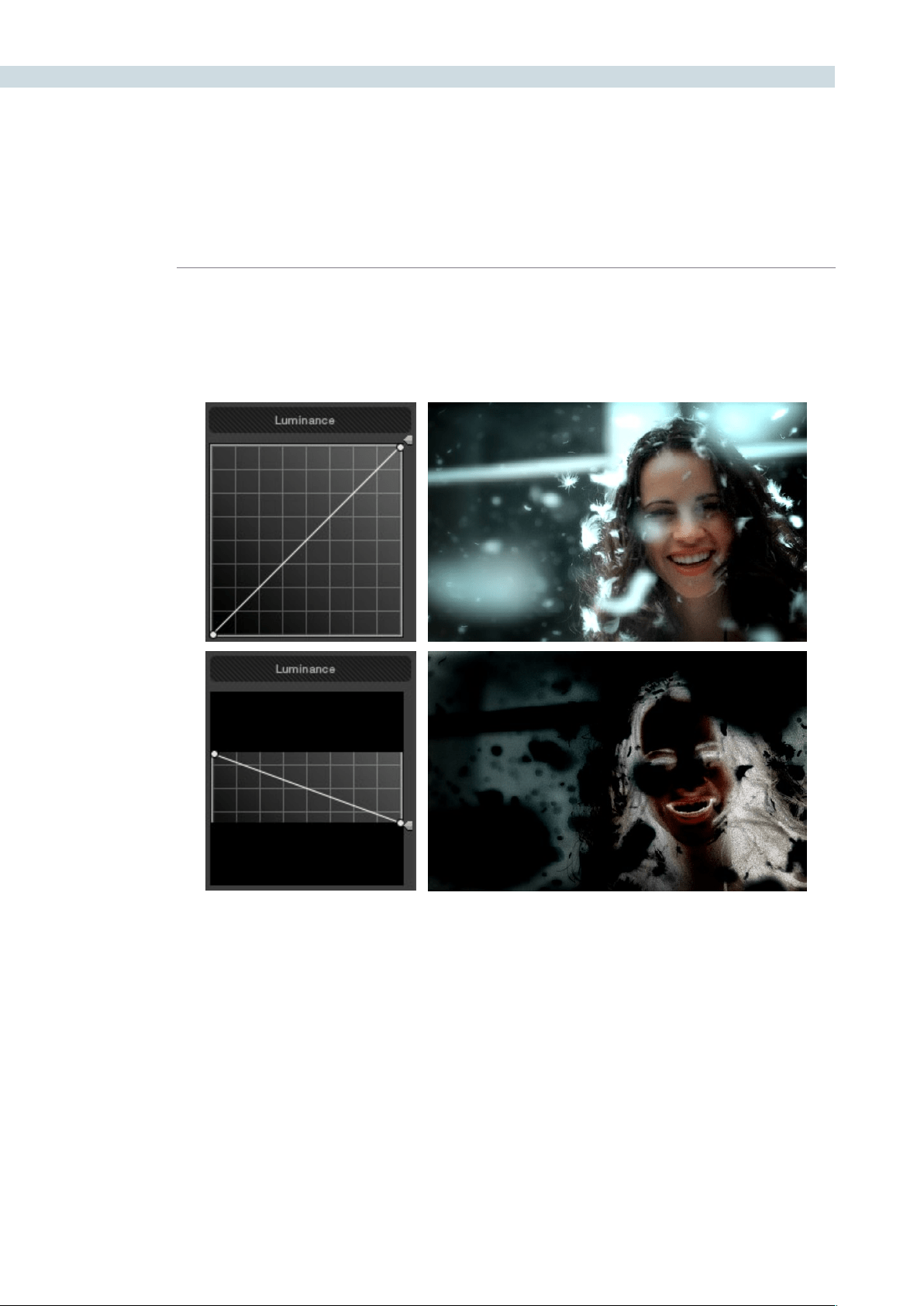
COLOR 258
YSFX Sliders
Each of the Custom curves (Y’, R, G, and B) has a vertical YSFX slider at the right of each curve control
that lets you invert any or all color channels, to create different types of special effects.
As with all other adjustments in the Color page, YSFX may be combined with Power Windows or HSL
qualification to limit channel inversions to specific portions of the image for creative effect.
Adjusting Custom Curves with the DaVinci Resolve Control
Surface
The controls that correspond to the Custom curves on the DaVinci Resolve control surface are available
by default when you first open Resolve and the rotary knobs on the center panel will be labeled
PRIMARIES. If these buttons are not visible, you need to switch to the Primaries controls using the
display buttons.
Top–Original image, Bottom–Image with the Luma channel inverted using the vertical YSFX slider
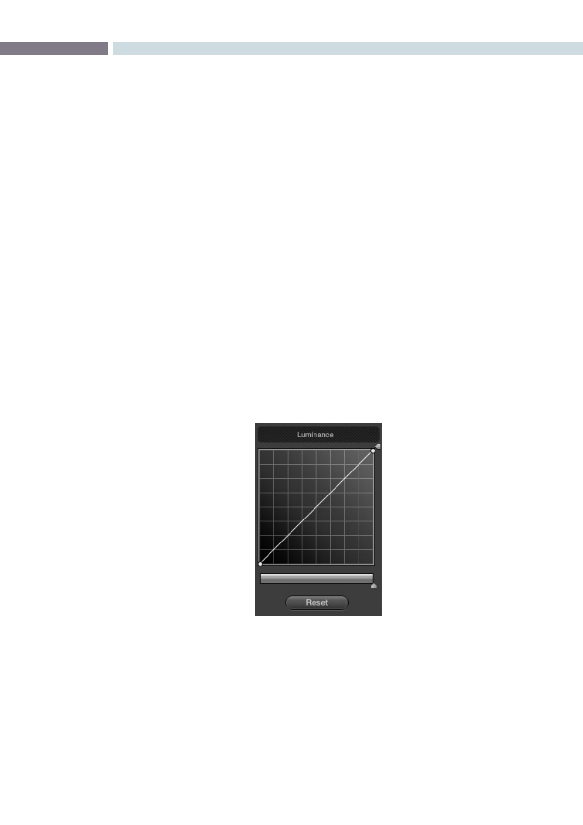
CHAPTER
COLOR
COLOR259
9
To open the primary curve controls of the DaVinci Resolve control surface, do one of
the following:
•PressthePRIMARIESdisplaybuttononthecenterpanel.
•IfthecenterpaneliscurrentlyinCURVESmode,thenpresstheMAINdisplaybutton
on the center panel.
The rotary knobs on the center panel update to show the CHANNEL OFFSET/
CUSTOM CURVES and YSFX controls.
To make curve adjustments:
•AdjusttheDARKLUM,MID-DARKLUM,MID-LIGHTLUM,orLIGHTLUMrotaryknobs.
By default, all adjustments you make using these controls are ganged across all
four YRGB curve controls. However, if you turn Custom Curve ganging off, then these
controls only affect the Luminance curve.
These controls correspond to the following default control point positions on the curve controls.
You also have the option of using the fourth trackball from the left to adjust individual control points
on curves to any position you like. This works for all curves in DaVinci Resolve that have control
surface mappings.
Default control points created by the primary curve control rotary knobs of the DaVinci Resolve
control surface; from left to right, DARK LUM, MID-DARK LUM, MID-LIGHT LUM, LIGHT LUM
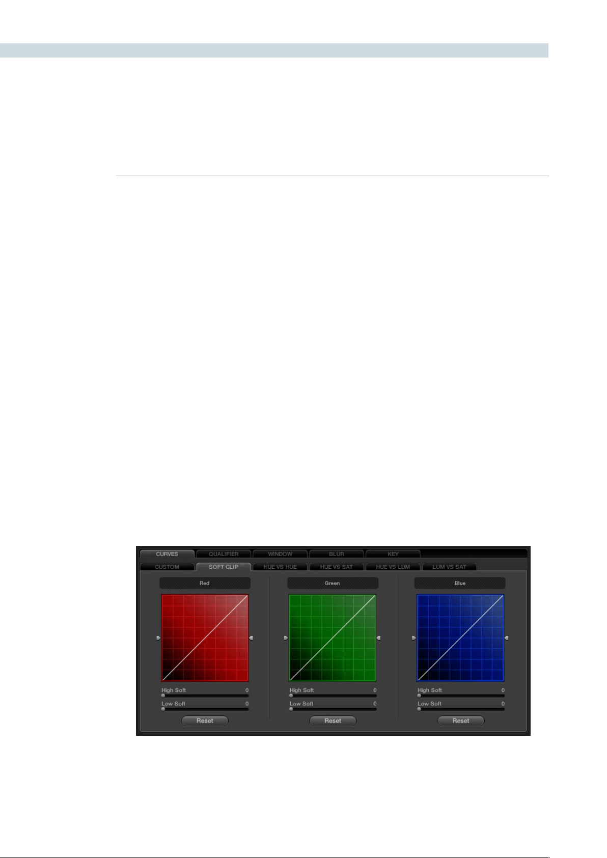
COLOR 260
Methods of selecting and adjusting individual control points using the master trackball of the
center panel:
To select a control point to adjust:
Spin the fourth ring control to the left or right to select the next
control point in that direction. It takes about half of a turn to select
another control point.
To move a selected control point:
Adjust the fourth trackball to move the control point up, down,
left, or right. Selected control points are constrained between
whichever control points are to the left and right.
Another set of rotary knobs let you adjust Curve Mix and YSFX parameters.
To adjust the Curve Mix sliders:
•AdjusttheLUMCURVE,REDCURVE,GREENCURVE,orBLUECURVE
rotary knobs.
To make YSFX adjustments:
•AdjusttheLUMYSFX,REDYSFX,GREENYSFX,orBLUEYSFXrotaryknobs.
About the Soft Clip Tab
The Soft Clip tab provides an interface for adjusting highlight and shadow soft-clipping on a per-clip
basis. This is in contrast to the Generate Soft Clip LUT settings of the LUTS tab within the Config page,
which let you set one simplified soft-clipping setting for the entire program.
The curve Clipping controls
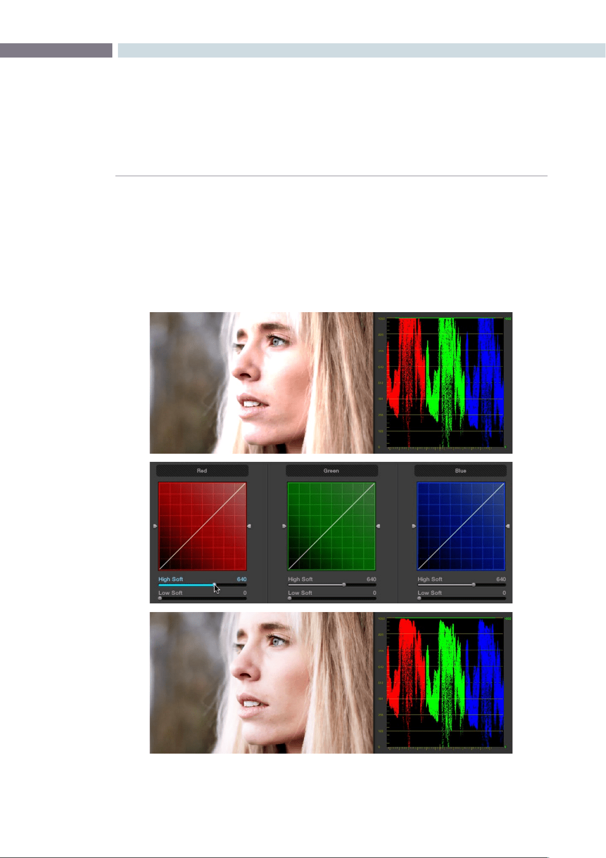
CHAPTER
COLOR
COLOR261
9
Soft-clipping lets you apply a “knee” to any clipping that occurs at the upper or lower extremes of the
image, and can be used to quickly ease off any unpleasantly harsh clipping that may occur as a result
of blowing out the whites or crushing the shadows.
In the following example, the screenshot at top has had the highlights deliberately blown out by boosting
the highlight contrast. As you can see, the edges of the clipped area lack detail. The screenshot at bottom
shows the same image with soft clipping increased for all three color channels; the result retrieves detail,
compressing the highlights to bring the tops of each color channel back within the allowable range.
Top–blown out highlights, clipping appears at the top of the RGB Parade. Middle–High Soft clipping raised in all
three channels. Bottom–the resulting compressed highlights retrieve detail
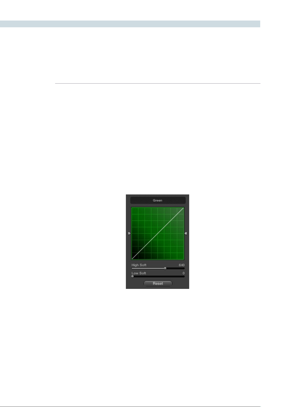
COLOR 262
Ganging and Unganging Soft Clip Curves
Soft clipping can be simultaneously applied to all three color channels by ganging them together and
is enabled by default. Alternatively you can disable soft clip ganging to individually adjust each channel.
For example, using soft clipping on individual channels can be useful for legalizing RGB out-of-gamut
errors for channels that over or undershoot your QC standards.
To enable or disable Soft Clip ganging:
•Right-clickanywherewithintheSoftCliptab,butoutsideofthecurveadjustment
boxes, and choose Gang Clips from the resulting menu.
Note: Applying too much soft clipping to individual color channels may add an unwanted color tint to
the corresponding highlights or shadows of an image. To avoid this, use the soft clipping parameters
with ganging enabled to clip all three color channels equally.
Whether all channels are ganged or not, soft clipping is controlled via four sliders available to each
color channel.
High Clipping Point
The High Clipping Point vertical slider, to the right of each clip curve control, lets you adjust the maximum
signal level above which the signal is clipped. Any pixels above the clipping level are made equal to the
clipping level.
The High Clipping Point defaults to a digital level of 1023 relative to the DaVinci Resolve internal video
scopes. Lowering this slider causes the highlights of the image to clip at a lower level, resulting in lower,
dimmer maximum levels.
Individual soft and clipping point sliders identified
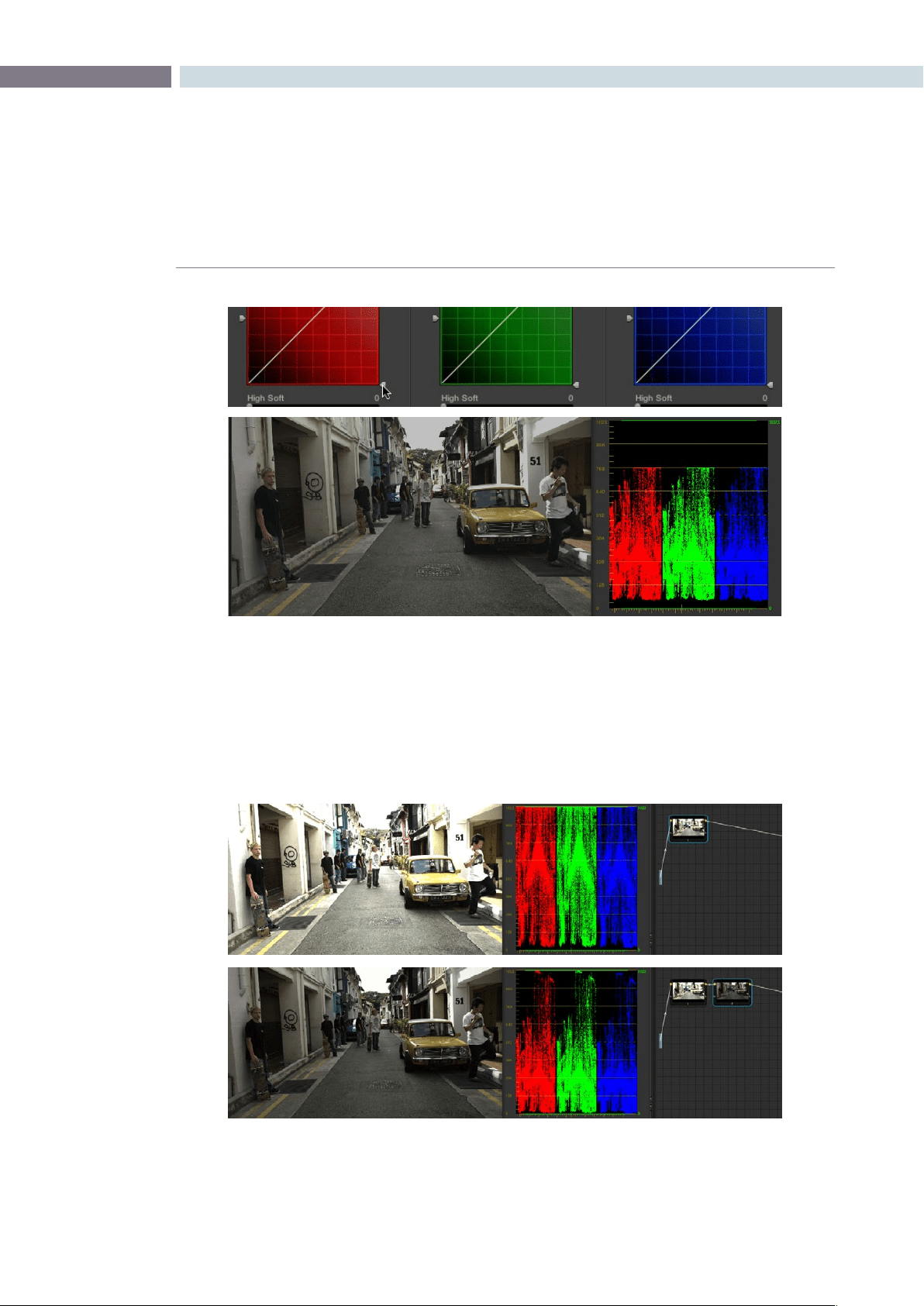
CHAPTER
COLOR
COLOR263
9
At the default middle position, image data that you push above 1023 on the internal scopes is preserved,
and passed through the image processing pipeline to subsequent nodes. For example, in the following
two screenshots, the highlights in the screenshot at top are blown out raising the gain dramatically in
node 1. In the screenshot at bottom, a subsequent adjustment in node two lowers the gain and retrieves
all the previously clipped values.
Lowering the High Clipping vertical slider, seen at top, reduces the maximum values that are
possible within in that node.
Top–the image is clipped using the Gain control in node 1; Bottom–image data that was clipped in node 1 is
retrieved in node 2 by lowering the Gain control. This illustrates the preservation of deliberately clipped data.
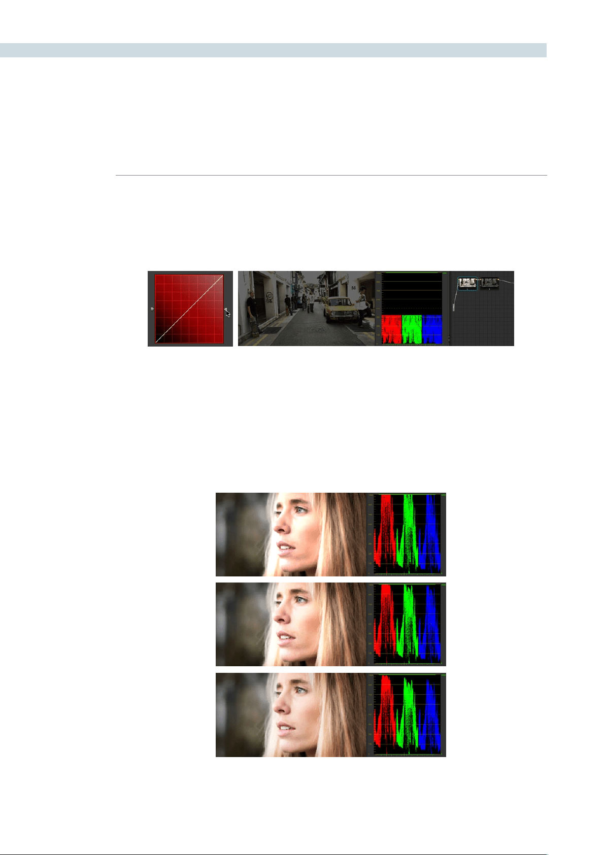
COLOR 264
However, if at any point in a node tree you lower the High Clip vertical slider, even by a single digit, all
image data above the new clipping threshold is discarded from that node forward. In the following
example, the High Clip slider in node 1 is lowered. The result is that all clipped image data is discarded.
As a result, when node 2 lowers the gain, there is no image detail left to retrieve, and all three channels
exhibit flattening.
High Soft
The High Soft slider sets the threshold, below the clipping point, at which highlights begin to compress
before hard clipping. At 0, no soft clipping occurs. As you raise this value, more and more of the clipped
highlight values are compressed, rather then clipped, resulting in softer, more pleasant “glowing”
highlights. In the following screenshots, an image with deliberately boosted highlights is shown with
High Soft set to 0, 500, and 1000, so you can see the difference.
Top–Gain is raised to blow out highlights; Middle–High Soft is set to 500, compressing the clipping in the
highlights; Bottom–High Soft is set to 1000, completely compressing the highlights
Lowering the High Clip slider in node 1 forces all image data above the new High Clip threshold to be irretrievably
discarded. Clipped data cannot be brought back by subsequent nodes.

CHAPTER
COLOR
COLOR265
9
Important: Image data that was clipped “in camera” is not necessarily retrievable using the Soft Clip
controls, although there may be some preserved overhead in the highlights of Y’CbCr-encoded
video data.
Low Soft Clipping Point
The Low Soft Clipping Point vertical slider, to the left of each clip curve control, lets you adjust the
minimum signal level at which the signal clips. This defaults to a digital level of 0 relative to the DaVinci
Resolve internal video scopes. Raising this slider causes the shadows of the image to clip at a higher
level, resulting in lighter minimum levels, and possibly a milkier image.
Low Soft
The Low Soft slider sets the threshold, above the minimum clipping point, at which shadows begin to
compress before hard clipping. At 0, no soft clipping occurs. As you raise this value, more and more
of the clipped shadow values are compressed, rather then clipped, resulting in a softer, more pleasant
rolloff in the shadows.
Using Soft Clipping Controls with the DaVinci Resolve Control
Surface
The soft clipping controls can also be manipulated using the DaVinci Resolve control surface, which
provides separate controls for ganged and individual color channels.
To open the soft clipping control on the DaVinci Resolve control surface:
•PresstheCLIPSdisplaybuttononthecenterpanel.
To exit the soft clipping controls:
•PresstheMAINdisplaybuttononthecenterpanel.
To make a ganged soft clipping adjustment:
•AdjusttheMASTERCLIPorMASTERSOFTrotaryknobsoftheSCENEWHITE
CLIPS or SCENE BLACK CLIPS control groups. There are 4 individual knobs.
These controls adjust all four corresponding YRGB High Soft, High Clip, Low Soft, or
Low Clip parameters simultaneously.
To adjust soft clipping for individual color channels:
•AdjusttheRED/GREEN/BLUECLIPorRED/GREEN/BLUESOFTrotaryknobsofthe
SCENE WHITE CLIPS or SCENE BLACK CLIPS control groups. There are 12
individual knobs.
Each control adjusts an individual YRGB color channel.
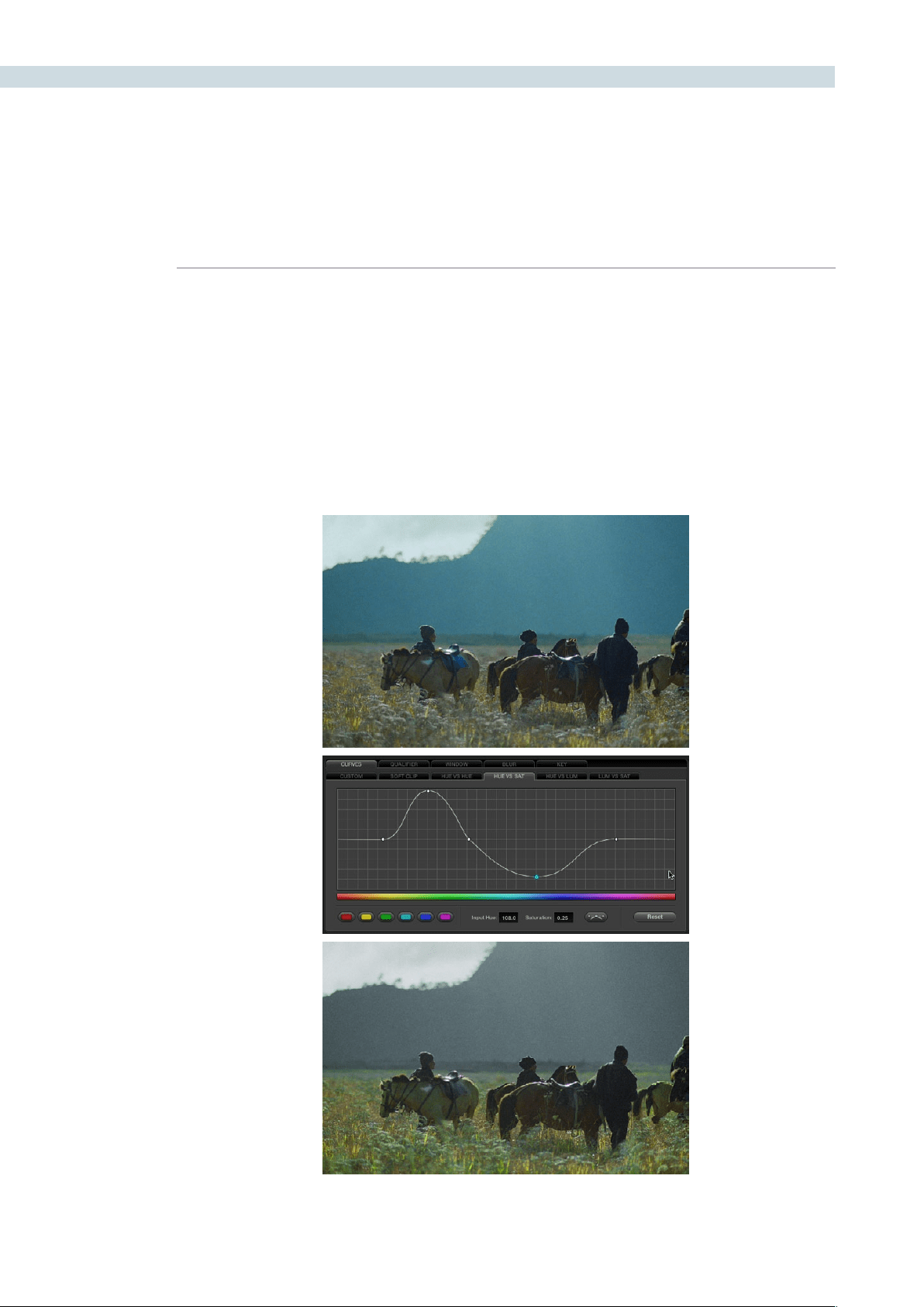
COLOR 266
About the Hue and Sat Curves
Three sets of hue curves, and one additional Lum vs Sat curve, let you make other curve-based
alterations to the image. Whereas the Custom curves let you make adjustments to the color channels
of an image based on tonality, for example boosting the red channel in the highlights while lowering it
in the shadows, the hue curves let you make adjustments to the hue, saturation, or luma of elements in
an image, based on their hue.
For example, you could use the Hue vs. Sat curve to selectively lower the saturation of everything that’s
blue, while raising the saturation of everything that’s green.
Top–Original image, Bottom– the image as altered by the Hue vs. Sat curve shown in the middle
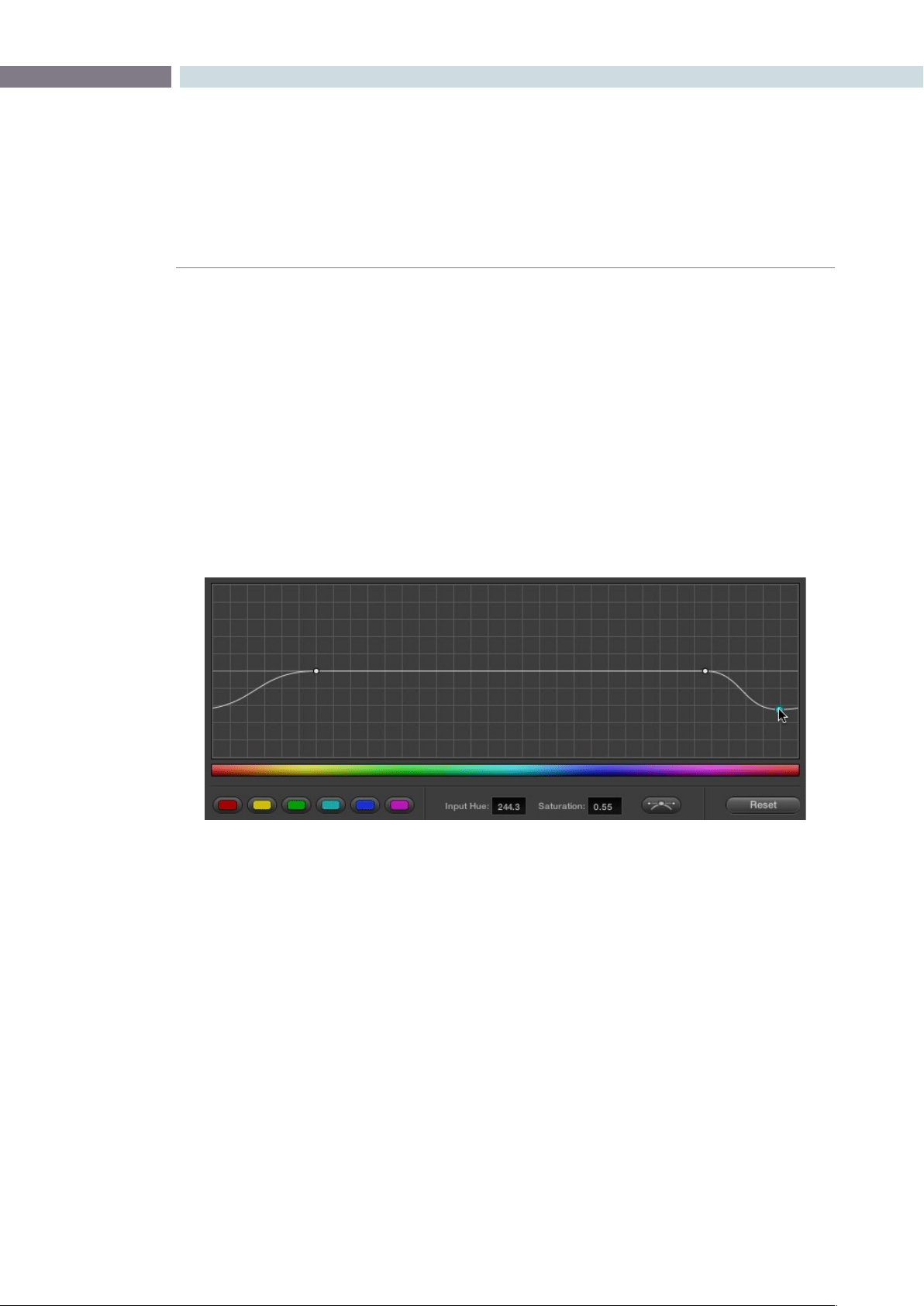
CHAPTER
COLOR
COLOR267
9
You can use these curves to quickly make adjustments similar to those made using HSL qualification,
but with one critical difference. Curve adjustments are mathematically smoother then the matte-limited
adjustments of HSL qualifiers, so it can sometimes be easier to make specific alterations that blend
smoothly with the rest of the image, without the potential for problems at the edges that can sometimes
be an issue when keying with qualifiers.
On the other hand, it can often be easier to define more distinct boundaries between separate elements
using HSL qualification. Only time and experience will help you determine which tools are best for
which situations.
Unlike the Custom curves, which default to a diagonal position where lower-left represents the black
point and upper-right represents the white point, Hue and Sat curves are flat. In the case of the Hue vs
Hue/Sat/Lum curves, the horizontal range of the curve from left to right represents the overall range of
possible hues, from red through green through blue and then cycling back to red.
Because the range of hues cycle smoothly from the left to the right edge, changes that affect the curve
near the left boundary of these curves loop smoothly around to the right boundary, and vice versa, such
that the left and right sides of the curve always move together as seen in the above screenshot.
Important: When using Hue Curves, the range of hue that you isolate with control points is always
relative to the RGB input connected to that node. That means if you change the hue of a shirt from blue
to red using Hue vs. Hue and you then want to raise the shirt’s saturation with the Hue vs. Sat curve
within the same node, you need to add control points to the same range of blue both curves.
Image sampling for Hue and Sat curves
There’s an additional way to use Hue Curves in Resolve. Whenever one of the Hue vs Hue, Hue vs Sat,
Hue vs Lum, and Lum vs Sat curve tabs are open, clicking or clicking and dragging over any range of
pixels within the viewer area samples the hues and/or image tonality of that region of the picture, and
automatically places three control points on the currently open curve that correspond to the range of
color and contrast you sampled.
Adjustments at one end of a Hue curve loop around to the opposite end
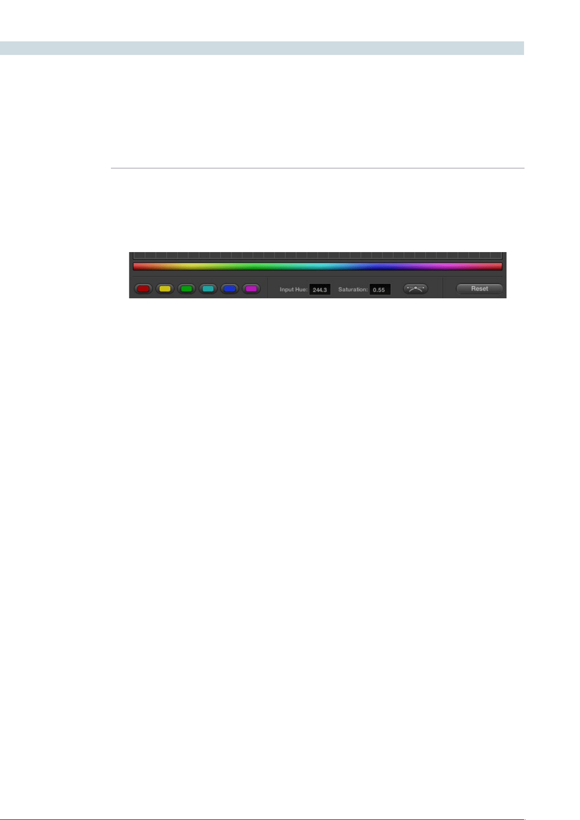
COLOR 268
Additional Controls in the Hue and Sat Curves
While the Hue vs Hue, Hue vs Sat, Hue vs Lum, and Lum vs Sat curves can be adjusted similarly to the
Custom curves, they have additional controls running underneath the curve graph.
Hue/Luma range buttons: The hue curves each have six buttons for automatically adding
control points to manipulate the red/yellow/green/cyan/blue/
magenta ranges of hue. Clicking any of these buttons adds
three control points; two to define the outer range of hue to be
adjusted, and a middle control point that you use to make the
adjustment.
Input and Output (Hue Rotate/Saturation/Lum) fields:
These two numeric fields correspond to the horizontal and
vertical adjustment values for the currently selected control
point. Click any control point on a curve to view or alter these
values. The label of the second field depends on the curve that’s
selected.
Enable Bezier button: Turning this button on forces a curve to use Bezier control
handles, rather then the default DaVinci Resolve curve control
points, to manipulate each control point on the curve. With
Bezier handles enabled, click any control point to reveal its two
Bezier handles. Drag either handle to alter the shape of the
curve at that control point.
The following sections describe each available curve in more detail.
Additional Hue curve controls from left to right, Hue range buttons, Input/Output fields,
Enable Bezier button, Reset button
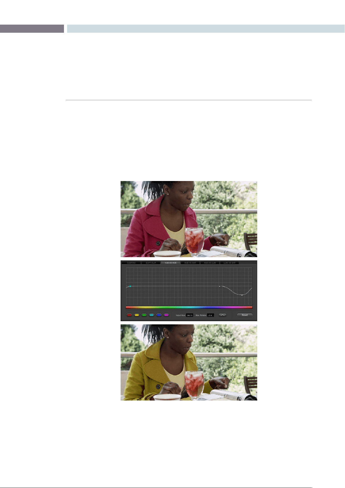
CHAPTER
COLOR
COLOR269
9
Hue vs Hue
The Hue vs Hue curve lets you remap any hue to any other hue. In the following example, the image at
top is the unadjusted original. The image at bottom has had the magenta jacket remapped to an olive
green via a set of three control points.
One excellent use of the Hue vs Hue curve is to quickly and subtly alter elements that require only minor
adjustments. For example, a sky that appears a bit too cyan can be made into a richer shade of blue
with a small adjustment.
One excellent use of the Hue vs Hue curve is to quickly and subtly alter elements that require only minor
adjustments. For example, a sky that appears a bit too cyan can be made into a richer shade of blue
with a small adjustment.
Top–Original image, Bottom– the image as altered by the Hue vs. Sat curve shown in the middle
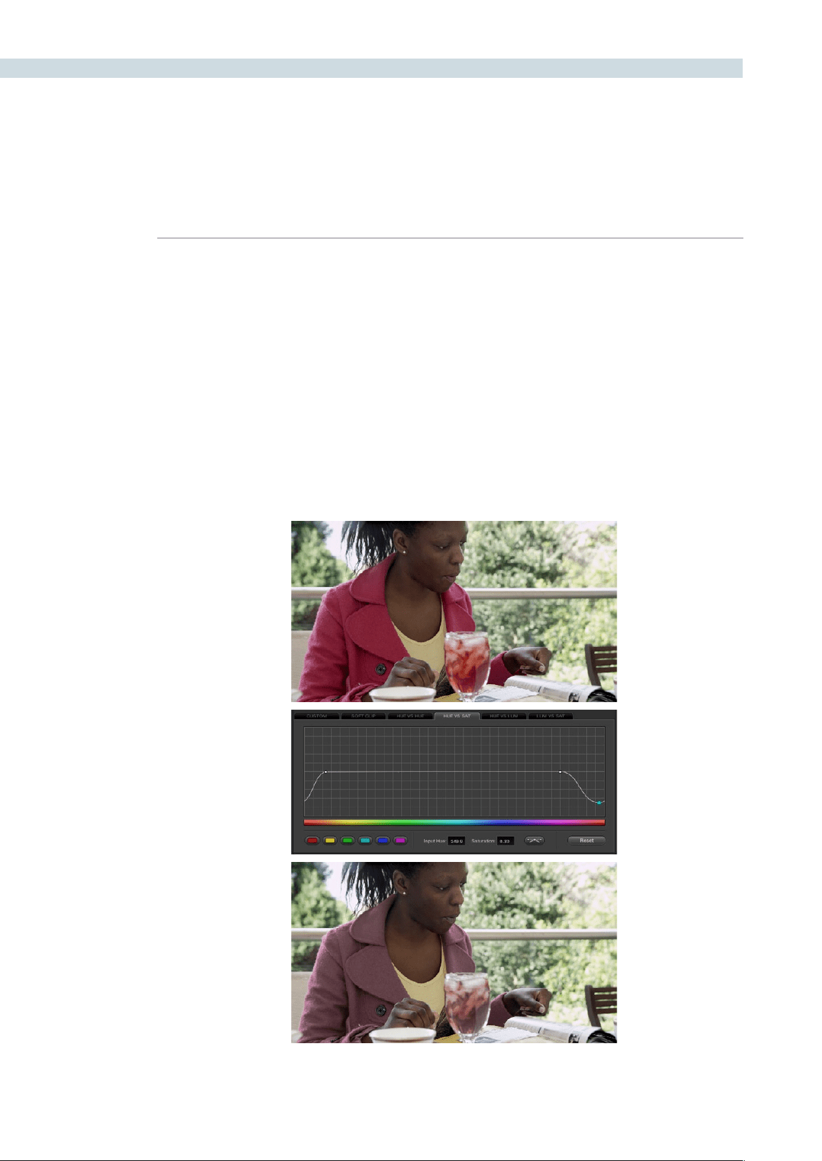
COLOR 270
Hue vs Hue is also useful for making more radical changes to elements that might be too noisy to
successfully key using the HSL qualifier controls. For example, red autumnal foliage blowing in the wind
might result in a chattery matte, but you can use the Hue vs Hue curve to change all reds to greens,
without having to worry about aliased matte edges giving your correction away.
Hue vs Sat
The Hue vs Sat curve lets you selectively alter the saturation of any hue within the image. This is a
terrific tool for creative effect, allowing you to quickly and easily boost the saturation of elements you
want to catch the viewer’s eye, while reducing the saturation of elements you’d prefer the audience not
dwell upon.
This can be extremely useful for legalizing oversaturated overshoots or undershoots during a QC pass.
For example, desaturating reds that are off the charts while leaving everything else alone.
Lowering the saturation of the woman’s jacket using the Hue vs. Sat curve; Top–original image,
Bottom–altered image

CHAPTER
COLOR
COLOR271
9
The Hue vs. Sat curve can also be a powerful tool for increasing the color contrast of images that seem
lackluster and one-dimensional. By boosting the saturation of colorful elements that are distinct from
the dominant palette of a scene, you can add variety to an otherwise monochromatic image.
Hue vs Lum
The Hue vs Lum curve lets you increase or decrease the lightness of elements of specific colors.
This is a tricky curve to use with highly compressed footage, as it can quickly reveal artifacts in the
image if you aren’t careful. However, if you’re working with very high-quality footage, this can be a great
tool to darken specific hues to add richness and depth, or to lighten colorful elements that you want to
draw attention to.
Darkening the woman’s jacket using the Hue vs. Lum curve; Top–original image, Bottom–altered image
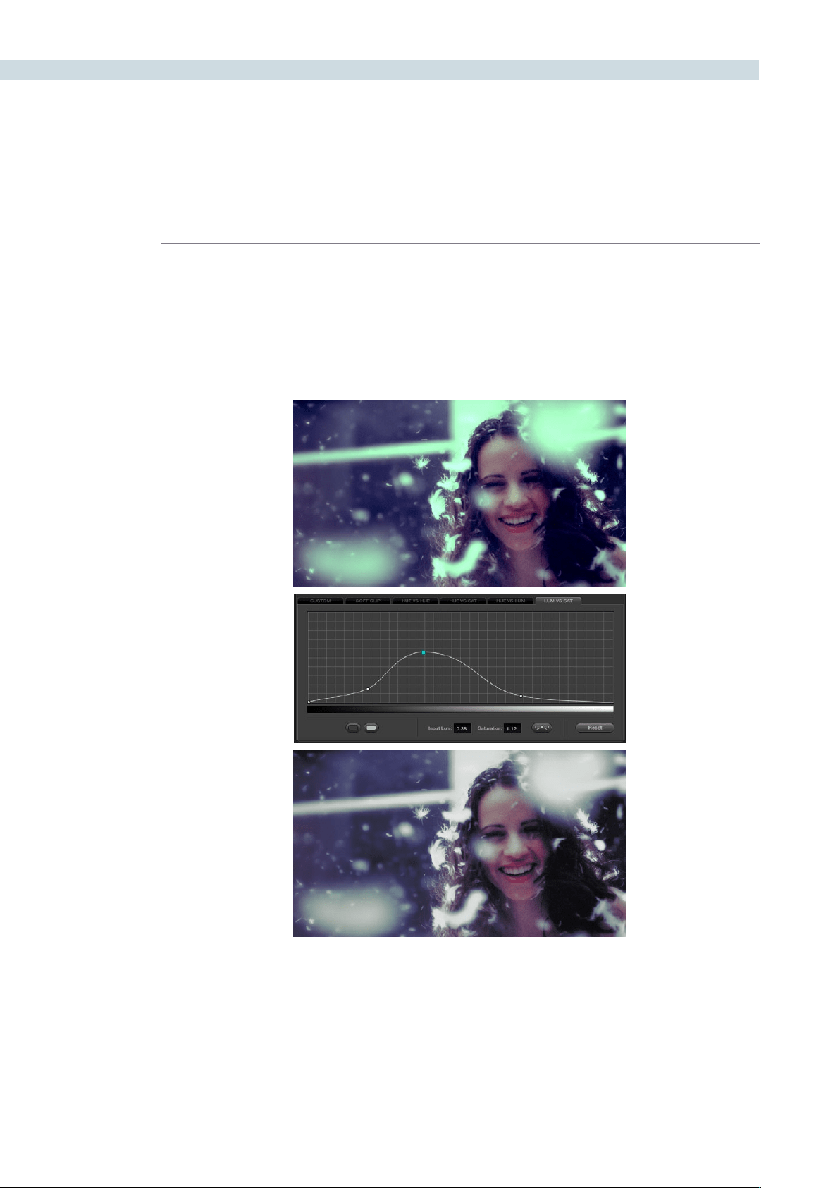
COLOR 272
Lum vs Sat
The Lum vs Sat curve is like the Custom curves in that alterations to the saturation of an image are
based on image tonality, rather then hue. In the following example, the Lum vs Sat curve is being used
to selectively decrease the saturation of everything falling into the highlights and shadows of the image,
while increasing the saturation of everything within the midtones.
This is an outstanding curve to use for creative effect, for example, slightly boosting saturation within
the midtones while reducing saturation in the shadows to increase the depth of the darkest portions of
the image. It’s also a great curve to use to solve QC violations. For example, if you have illegal saturation
in the highlights of an image, you can use the Lum vs Sat curve to lower the specific values that are
causing problems cleanly and smoothly.
Selective desaturation in the shadows and highlights, along with increased saturation in the midtones,
using the Lum vs. Sat curve; Top–original image, Bottom–altered image

CHAPTER
COLOR
COLOR273
9
Using Hue and Sat Curves With the DaVinci Resolve Control
Surface
Using these curves with the DaVinci Resolve control surface unlocks their speed, letting you make fast,
controlled adjustments to specific elements within each scene.
To open the Hue and Sat curve controls on the DaVinci Resolve control surface:
•PresstheCURVESdisplaybuttononthecenterpanel.
To exit the Hue and Sat curve controls:
•PresstheMAINdisplaybuttononthecenterpanel.
To adjust the principle color regions using knobs:
•Adjustoneofthe18rotaryknobsinthePRIMARIESCURVEGRADEcontrolgroups
corresponding to the RED/YELLOW/GREEN/CYAN/BLUE/MAGENTA colors paired
with HUE/SAT/LUM.
To sample a region of a shot to place curve control points:
1. Press the display button corresponding to the curve you want to adjust (HUE - HUE,
HUE - SAT, HUE - LUM, LUM - SAT).
2. Press the CURSOR button located above the fourth trackball.
3. Use the fourth trackball to move the onscreen cursor to the pixel you want to sample.
4. Press the first of the three buttons underneath the fourth trackball to sample the color
at the position of the cursor.
Three control points appear on the currently selected curve. The outer two control
points define region of the curve you’re adjusting. The center control point lets you
make the actual adjustment and selected by default.
5. To hide the cursor when you’re finished sampling, press the CURSOR button again.
Methods of selecting and adjusting individual control points using the master trackball of the
center panel:
To select a control point to adjust:
Spin the fourth ring control to the right or left to select the next
control point in that direction. It takes about half of a turn to
select another control point.
To move a selected control point:
Adjust the fourth trackball to move the control point up, down,
left, or right. Selected control points are constrained between
whichever control points are to the left and right.

COLOR 274
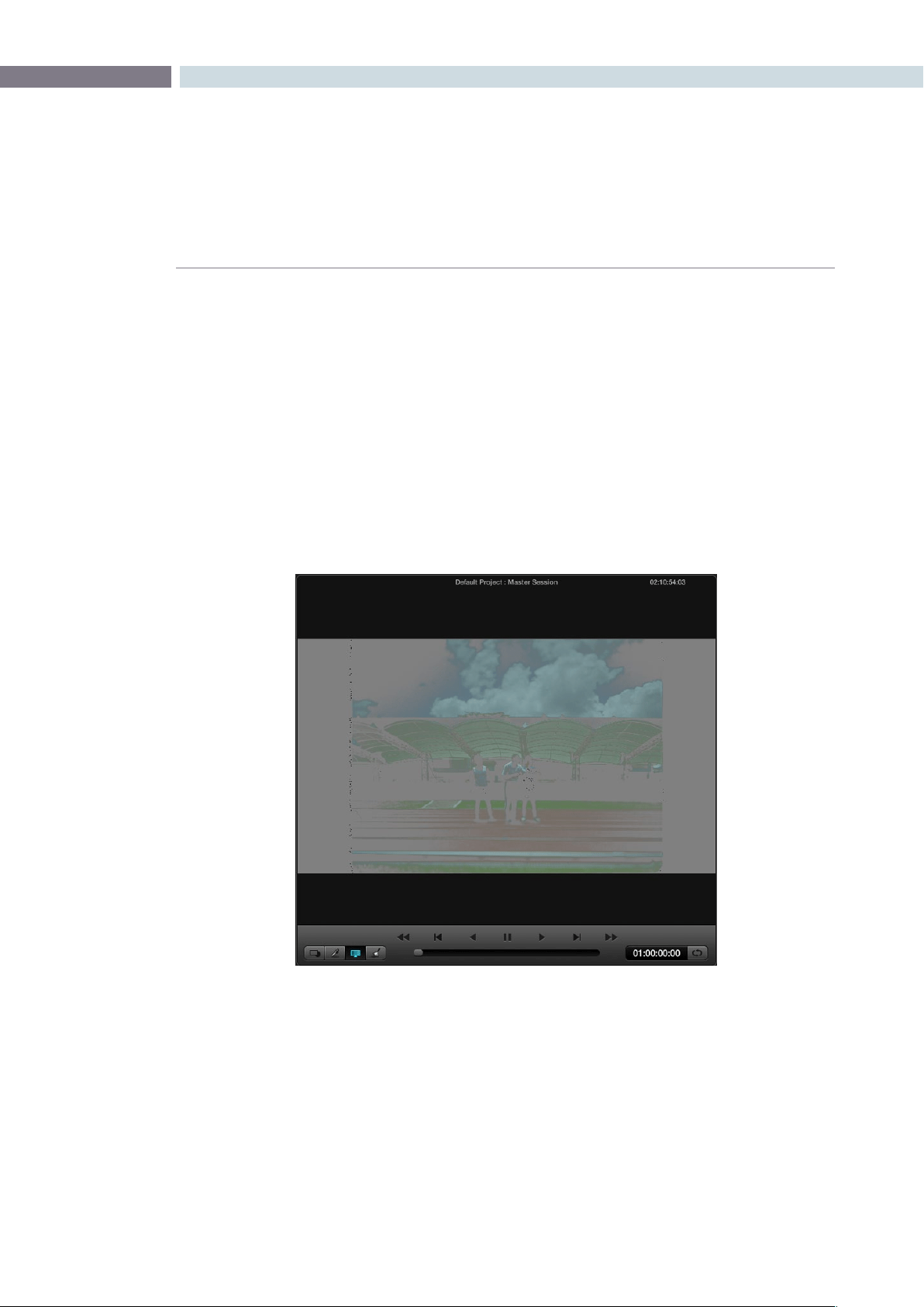
CHAPTER
COLOR
COLOR275
9
Hue, Saturation and Luminance Qualification
To change the grade on a specific section of an image, you must first select the portion you want to
change. One selection type is the Hue, Saturation, and Luminance (HSL) qualifier. Select the HSL sub
tab, place the cursor over the area of the image you wish to qualify, and select with the left mouse
button. You can adjust the qualification for the secondary color correction isolation immediately, but a
simplerwaytoviewtheselectedareaisbypressingthe‘Highlight’buttononthesecondarytab.
The image on the Viewer and Grading monitor will now only display the image that is qualified; everything
else will be replaced with gray. There is a high contrast mode set in the Config settings tab to make this
ablackandwhiteratherthangraycontrast.Underthe‘Highlight’buttonontheUI,theInvertbuttonwill
invert the Image and Qualifier controls, so instead of using the Qualifier controls to select the area to
make a change, you are in fact selecting the areas you will not change.
Highlighting the Qualified Areas
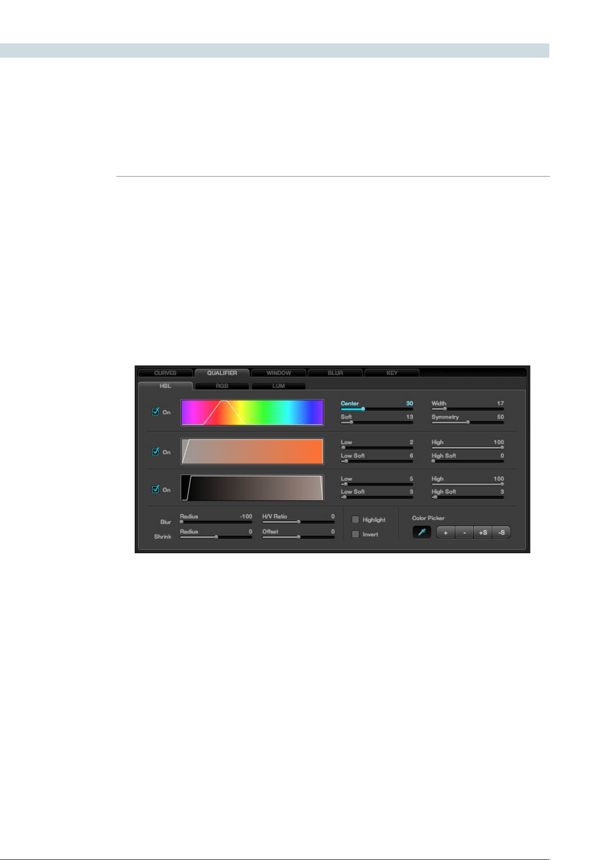
COLOR 276
Next adjust the Hue, Saturation, and Luminance Qualifiers to get a cleaner qualification. First, start with
the Hue Qualifier, which is shown as a rainbow colored bar to indicate the range of Hue values available.
When you select a color on the image to qualify with the cursor or mouse, the selected color will be
indicated within a white border on the Hue display. Adjusting the ’Center’ control, will make the white
bordermoveupanddownthedisplay.‘Width’isusedtonarroworbroadentherangeofthehues
selected. You will see the result on the Grading monitor as well as on the Hue display.
The‘Soft’controlwillchangetheattackangleofthequaliedhueselectionfromthenormalhardedge
toasofterramp.The‘Symmetry’controlchangesthissoftnessparameterateithersideofthehuerange.
Balanced symmetry has the soft slope even on each size, or one side of the control range can be hard
while the other soft.
HSL Qualifier
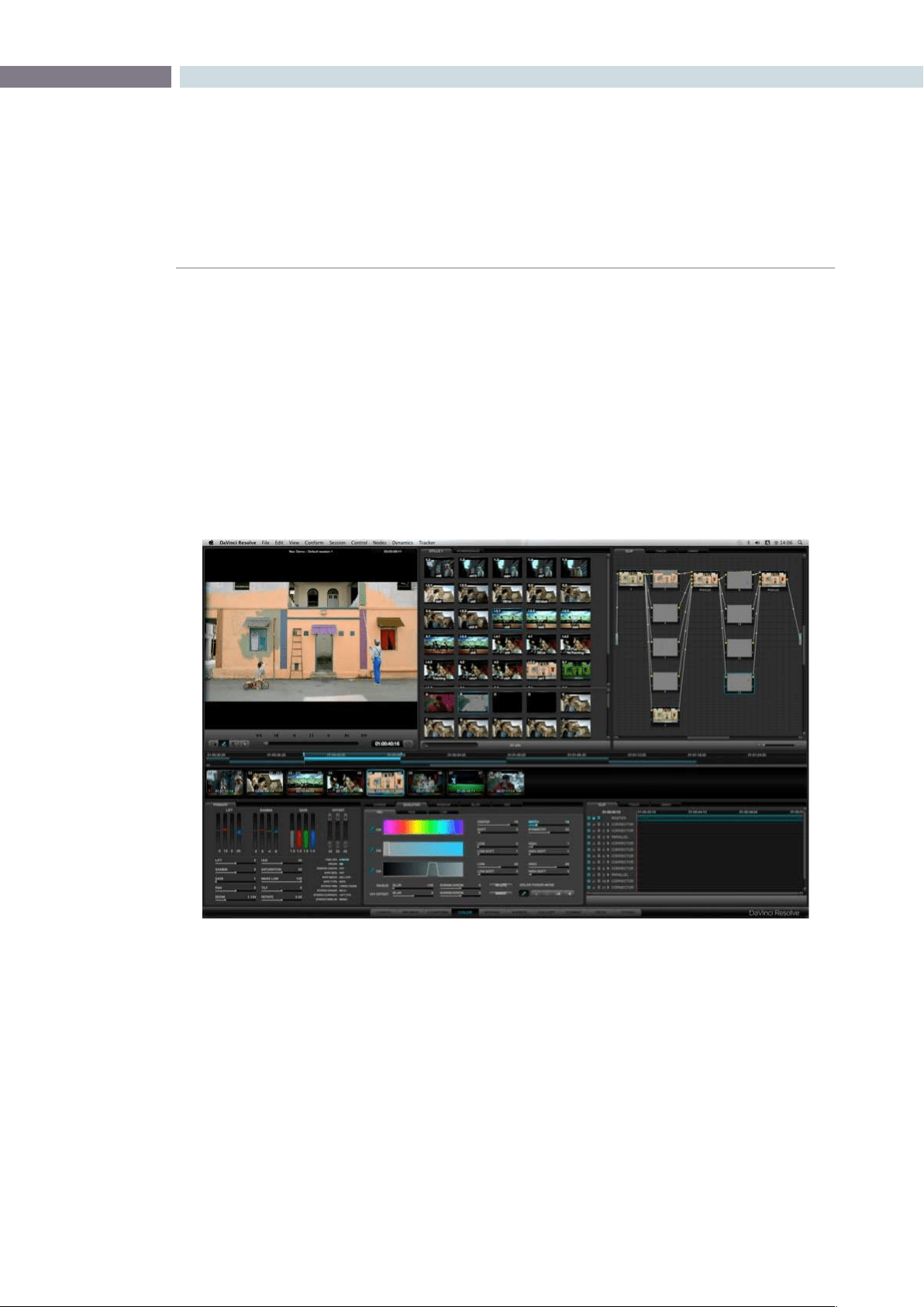
CHAPTER
COLOR
COLOR277
9
The next color band shows the Saturation range of the hue selected. Again, the white border is displayed
aroundthepixelvalueselected.The‘Low’and‘High’controlsadjusttherespectiveSaturationleveland
’Soft’ controls the slope to adjust the ramp on either side of this range. The same group of controls are
available for the Luminance settings, with the Luminance bar showing a black to white range.
OnceyouhavenishedwiththeQualieradjustments,pressthe‘Highlight’buttononceagainand
the picture will return to a Normal view. Now that you have qualified an area by its Hue, Saturation and
Luminance values you may use the Trackballs and other grading controls to adjust the color within the
qualified area.
You will notice the Node Graph display of this node and the thumbnail under the timeline will update to
indicate that a secondary grade is being made in this node.
RGB Qualification
If you select the RGB button within the Qualification window the qualifiers will be changed from Hue,
Saturation and Luminance qualifiers to Red, Green and Blue qualifiers. When this mode is activated, the
cursor position will read the Red, Green and Blue values rather than the Hue, Saturation and Luminance
values for the selected color. These have the same general control operations with Low, Low Soft, High
and High Soft adjustments.
Color Screen Qualifier
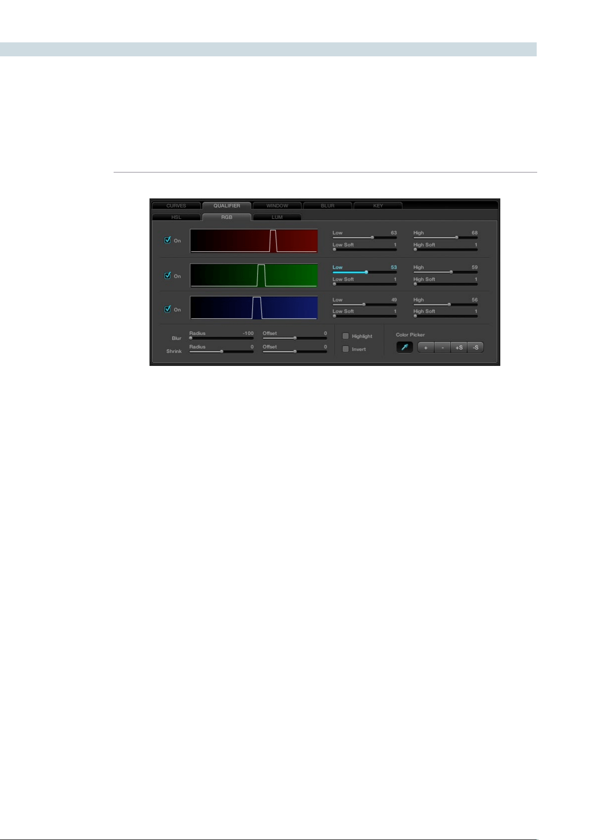
COLOR 278
Luminance Qualification
The next tab is for Luminance qualification. Its adjustments are the same as the Luminance parameters
on the HSL tab and have the same function, however in the LUM tab only Luminance values are used
to qualify the image.
Qualifier Blur
Within the Qualifier tabs there are a number of other controls, including the Qualifier Blur parameters.
At the bottom left of the Qualifier tab, the first control is for Blur and there are two parameters: Radius
and Offset. The blur range is quite large and the radius of the elements and their horizontal and vertical
offset range is equally large.
The second set of sliders is for Shrink and Grow. The qualifier, once set, can be shrunk a little or grown a
little, and again, you have a Range and Offset control.
Color Picker Mode
The Color Picker in DaVinci Resolve has a number of trim adjustments to assist in getting the right
selection of pixel values to use for the qualification. The controls are at the bottom right of the Qualifier
tab. The standard picker mode has the Color Picker icon selected. The other options change the Picker’s
selection of pixel values to modify the qualifier.
Whenselected,‘+’willchangethePickermodetoaddnewvaluestothequalierrange.
The‘-‘isusedtoremovesomevaluesfromthequaliedrange.IfyouselectaHue,forexample,and
remove a similar but different hue, the width range will decrease as fewer hues qualify.
The‘+S’canaddvalueswithsoftnessandthe‘-S’canremovevalueswithsoftness.
Be sure to return the Color Picker to the standard mode after making the trim adjustments to the
qualifier values.
RGB Qualifier
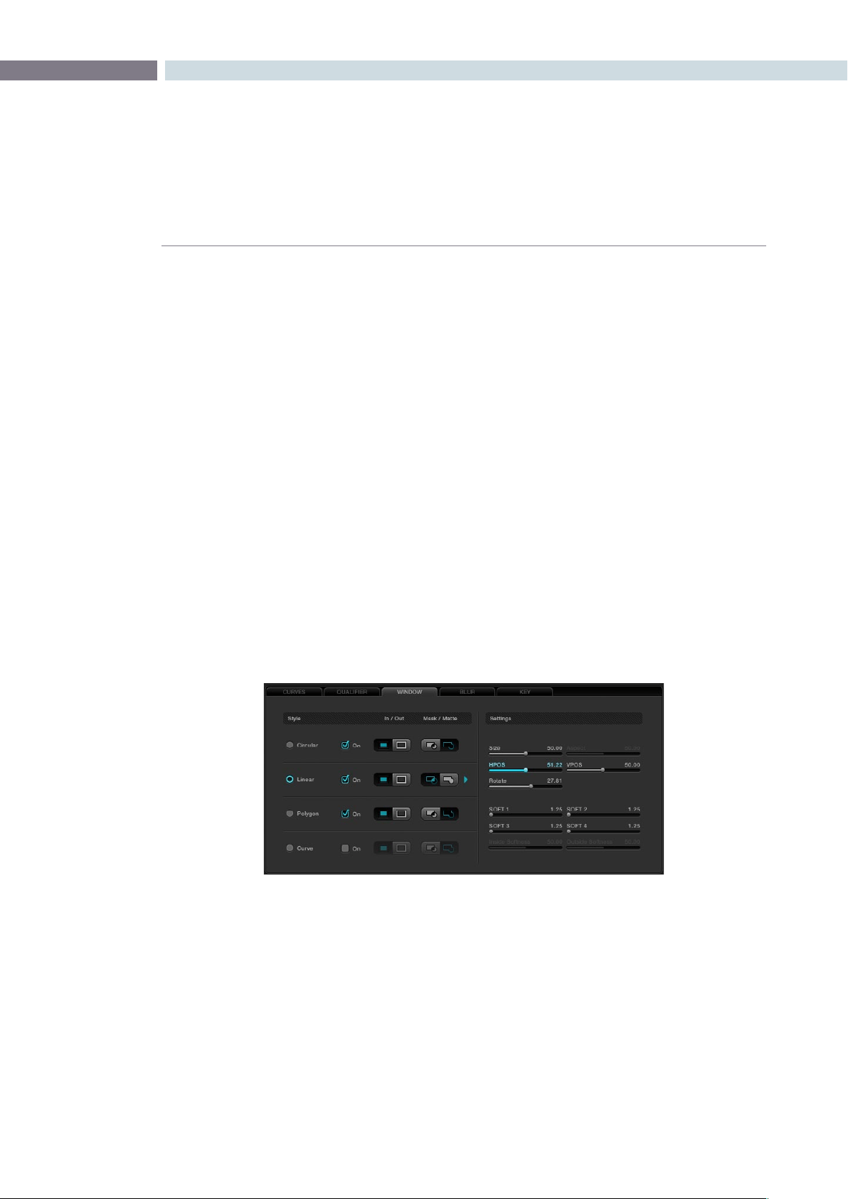
CHAPTER
COLOR
COLOR279
9
DaVinci Resolve has the famous DaVinci Power Windows, which provides a number of shapes to use
for Matte and Masking of image sections. Once you have made the Power Window, adjusting the grade
within the window area, or outside if invert is selected, is as easy as moving the trackballs. You will see
the result of the window and the correction applied within it on the Viewer display, and the final result is
the image that is seen on the Grading monitor. There are four window types: Circle, CPW; Linear, LPW;
Polygon PPW; and Curve, PCW (Bezier).
Power Windows may be used to isolate a primary or a secondary color correction. They are often used
with secondaries to permit fine qualification of the image and in Matte or Mask mode, depending on the
type of correction required. Using a Power Window in Mask mode is generally used when the window
is intended to mask out a portion of another Power Window or a Qualification.
DaVinci Resolve’s object tracking will be discussed later in detail, but it’s clear that windows placed on
an object to permit grading within or outside the window edge will only work if the object does not
move. The object tracker will allow you to create keyframes automatically for the windows to track
moving objects, making DaVinci Resolve Power Windows even more valuable.
Adjusting PowerWindows
Windows can be selected in a number of ways. On the UI, select the Window tab, then select the desired
window style. This also selects the settings controls for that window type. To see the window and adjust,
turn it on, select to grade Inside or Outside, and then choose whether to use the window as a Matte or
Mask. Change to a Matte or Mask to see the window on the UI display.
All Power Windows have a center point and a rotation handle. Rotation, or moving the window, is
managed using the rotation handle or the axis point. The center axis of the Power Window may be
moved using the control panel or by holding down the Ctrl key on the keyboard and dragging the
vertical rotation line to the area where you would like the rotation axis to be relocated to. To reset the
rotation axis to the image’s center position, simply hold down the Control key on the keyboard and
mouse click on the center rotation point.
To alter the size parameters of the Power Window, click on the cyan colored points that can be seen
in the Power Window cursor lines in the Viewer display and drag them with the mouse, or alter the
softness of the window, the aspect, size and even the rotation.
Power Windows
Window Tab
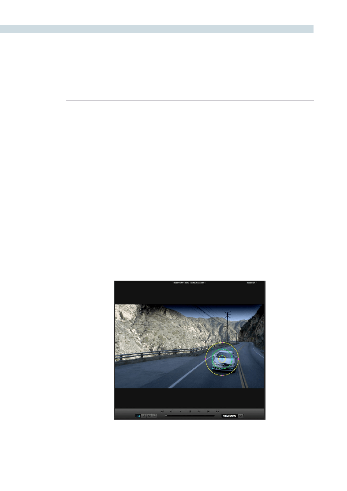
COLOR 280
Inside and Outside Window Grades
It is common to grade inside a Power Window to change the image in a particular area. However, if
you wish to adjust the grade both inside and outside the window independently, this is performed in
DaVinci Resolve with two nodes with a Link Control that sends the key signal from one node isolation
to another node.
Youcanmanuallyaddandlinkanode,orwiththeDaVinciResolveControlsurface,select‘AddOutside
Node’ on the Windows Soft menu to Add another node automatically and link the Alpha channel. You
can then select the first node and grade the image inside the window and select the second node and
correct outside the window. To add a Matte Link to a second node manually, connect the nodes by
clicking on the Arrow icon located to the right of one node, and then drag the mouse to the Arrow icon
located to the left side of the next node.
Circular Power Window
The Circular Power Window (CPW) can have its Horizontal and Vertical Position, Size and Aspect
changed as well as the Softness of the window’s impact on the underling image. Quite often, the CPW
is use to make a vignette. DaVinci’s Circular Power Window changed the industry as it permits very small
to large size settings with what seems to be infinite softness.
Use the CPW in a large wide aspect to make a grading impact on the entire top or bottom of the image.
Or, use it on a single eye of the talent to change the look.
Circular Power Window
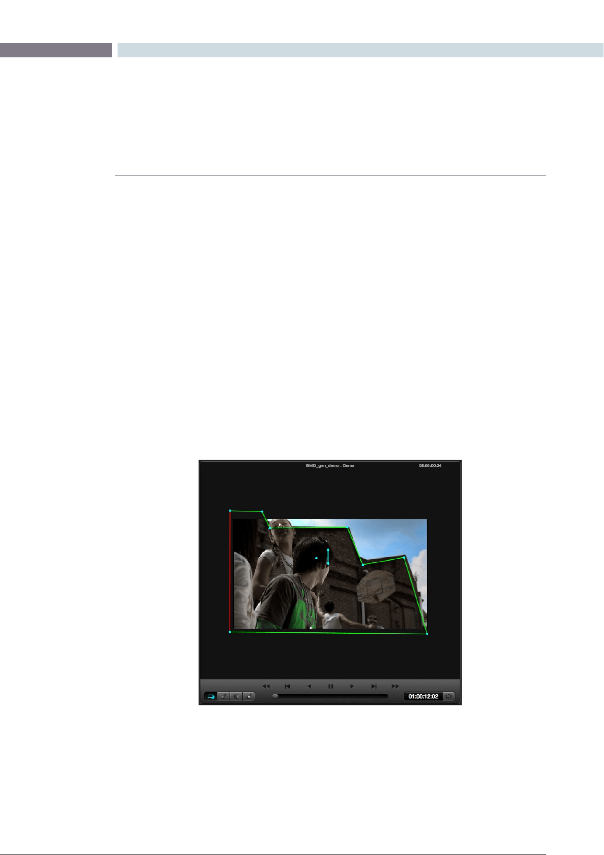
CHAPTER
COLOR
COLOR281
9
Linear Power Window
The Linear Power Window (LPW) first comes up as a square, however you may alter the position of the
corners and vary the softness for each side. This gives you the ability to create very unusual shapes with
LPW; these are often used for masks over circular windows.
Polygon Power Window
The Polygon Power Window (PPW) is a window with a maximum of 128 points. As with the other two
forms of Power Windows, you may apply softness to the shape and even apply auto tracking. The
Polygon Power Window also has individual softness for inside and outside the shape, as well as overall
Softness controls.
To add more points, move the mouse to the desired part of the shape and left mouse click on the window
line at the position where you need the point. Move the point by selecting the point and dragging it with
the mouse. To delete a point, select the point then center mouse click.
To change the center of rotation for the shape, press the Control key on the pull-out keyboard and drag
the cyan colored center graphic to the desired location. Apply separate inside and outside softness to
the shape by accessing the Isoft or Osoft controls with the mouse on the Window tab.
Polygon Power Window
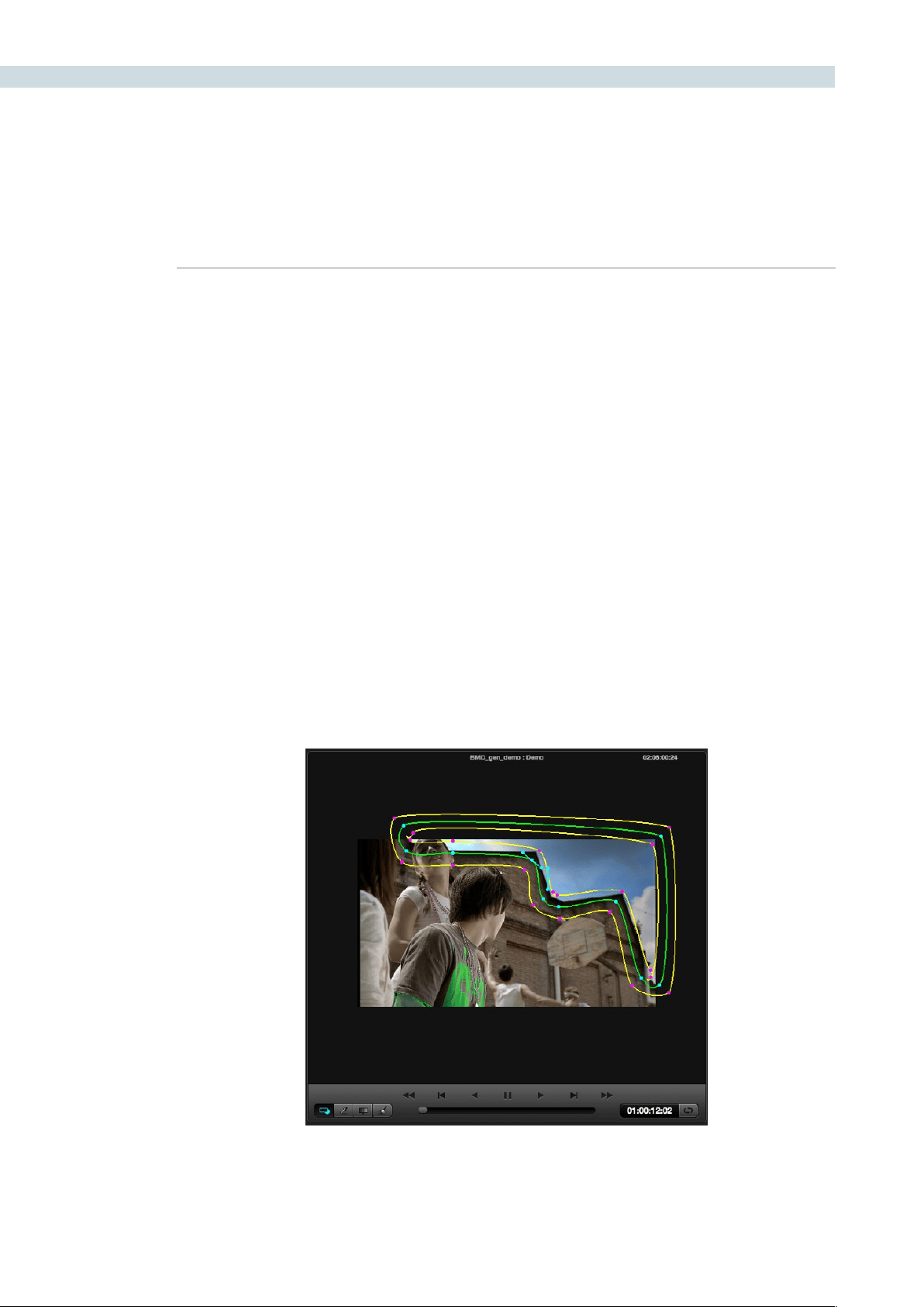
COLOR 282
Power Curve Windows
To add a Power Curve Window (PCW), or Bezier window as some colorists call it, selection of the
window style is no different to others for the UI or the DaVinci Resolve control panel. Unlike the other
available windows, there is no default points or shape for the Power Curve Window. Once the PCW is
enabled, the “Curve” may be created by clicking in the Viewer using the left mouse button. To complete
(close) the curve, press the middle mouse button or press the left mouse button on the first point of the
curve. You can adjust the curve using the control panel or the mouse.
Additionally, the inside and outside softness may be altered on a point-by-point basis by dragging any
of the magenta reference points to the desired position. As with all of the Resolve Power Windows, the
axis of rotation may be changed by holding down the control key on the DaVinci Resolve keyboard and
dragging the center reference point to the desired position.
You may change the “Power Curve” shape using the mouse. To add points, left mouse click on the curve;
to delete points, use the center mouse button over a point. To change the curvature, select one of the
handles attached to a curve point and adjust the curvature by keeping the left mouse button pressed
while moving the pointer. The curvature handles move opposite to each other in a locked fashion. To
moveasinglehandleatatimeyoumustkeepthe‘Shift’keypressedwhilemovingthehandle.
If you want to straighten an edge, double click on the corresponding curve point. When the edge is
straight, the curvature handles for that point are collapsed. To rotate a curve, select the central handle
of the curve (similar to other windows) and rotate. You can also select the central handle and Pan/Tilt
the entire curve.
PowerCurve Window
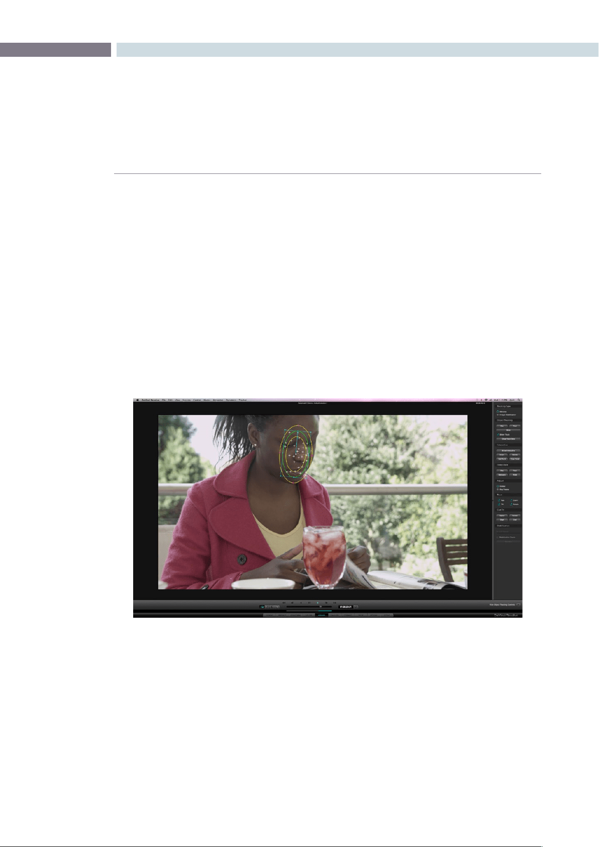
CHAPTER
COLOR
COLOR283
9
Power Window 3D Object Tracking
Whether it is a Circular, Linear, Polygon, or even a Power Curve Window, you will eventually need to
change the position of the window to follow a moving object within a clip. Fortunately, DaVinci Resolve
has a very powerful automatic tracking tool that can be used for tracking the position of an object
within a clip.
The Object Tracking operation is covered in detail within the Viewer screen description, but here are
some basics for the simple operation. Place the window over the object, switch to the Viewer screen and
opentheTrackingmenuontheright.IfDaVinciResolvelosestheobjectatanypoint,pressthe‘Stop’
button,makethenecessarywindowreposition,andenteramarkusingthe‘Mark’buttononthecontrol
panel. Start the track again from that point.
After the tracking procedure is finished you can still move the window, apply softness or change the
aspectandsize.Thetrackingfunctionscanalsobeselectedbypressingthe‘T’keyonthekeyboardfor
forwardtrackingor‘Shift-T’forreverse.
Object Tracking
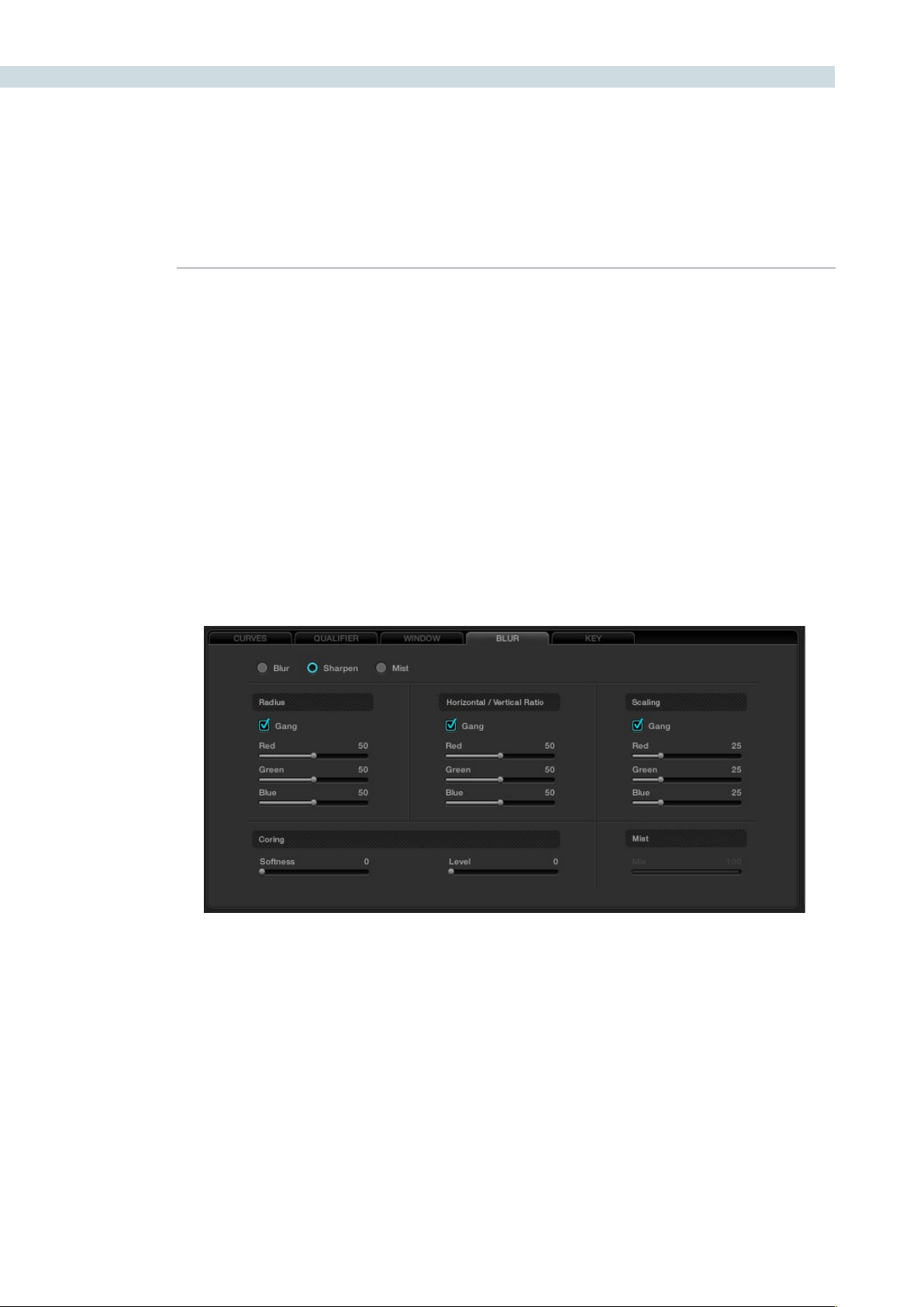
COLOR 284
The next tab on the Color screen is Blur, which holds the controls for Blur, Sharpen and Mist. The
algorithm for calculating this effect is a precision Gaussian filter, so very high quality adjustments can be
made. These controls share a common set of parameters and in fact Blur is the inverse of Sharpen so
the same control will give you one effect at one end of the range and another affect at the other.
Blur
When Blur is enabled, DaVinci Resolve will blur or defocus the image in real time. The two main
adjustments for blur are the Radius control which changes the size of the image area used by the
Gaussian algorithm to calculate the defocus effect, and the Horizontal/Vertical Ratio control which
changes the balance between the horizontal and vertical influence.
Each of these parameters are normally in Gang mode, which means the Red, Green, and Blue channels
are all affected evenly. You can deselect Gang mode and make individual adjustments on the UI or on
thecontrolpanelsbyselectingthe‘Master/Color’buttononthePrimarysoftmenutotogglebetween
Gang and individual color controls.
Blur Tab
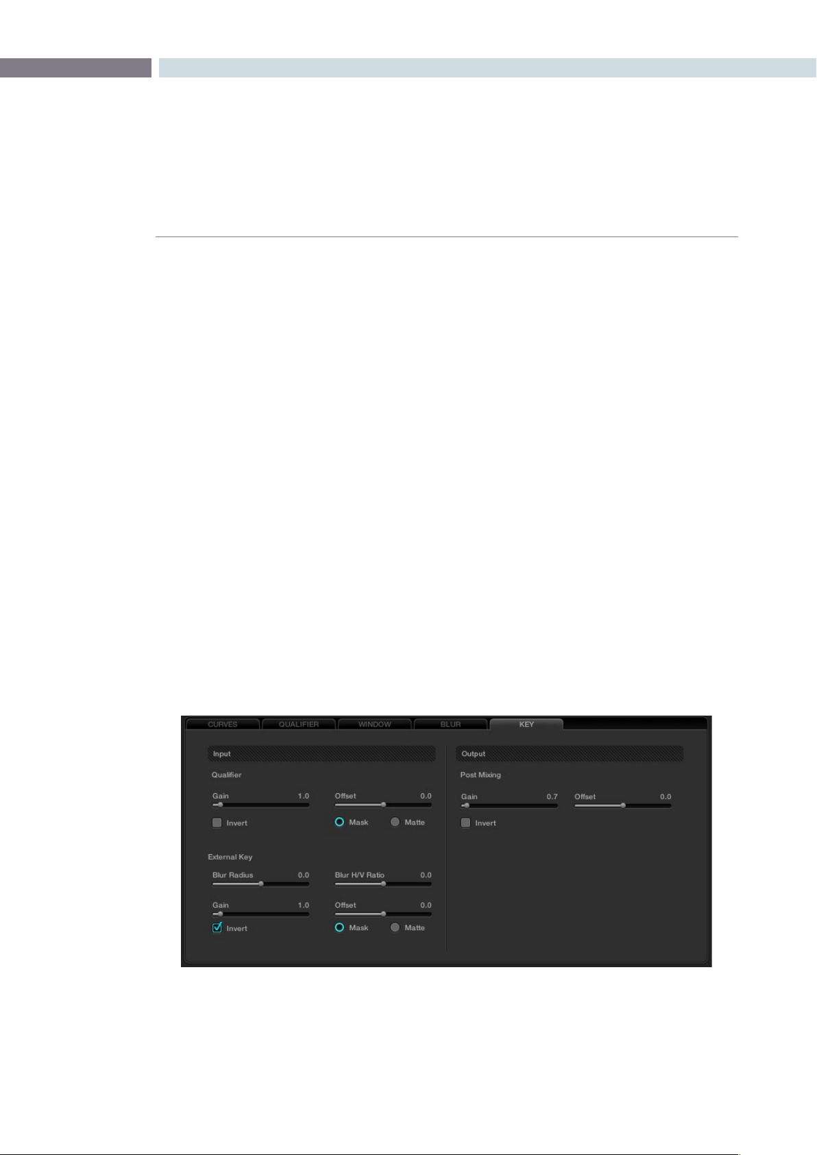
CHAPTER
COLOR
COLOR285
9
Sharpen
The Sharpen control can be adjusted via the Resolve control panel or with the mouse within the window
on the user interface.
The Sharpen control will enhance the image and the filters may be adjusted individually for Red, Green,
or Blue or, if Ganged is checked (which is typical), the change will be for all. Sharpen also has a scaling
control, again with a ganged and individual RGB values. The scaling adjustments change the recursive
filter within the Gaussian algorithm.
Finally, there is also a Coring control that makes this filter behave like an Aperture Correction control. The
Coring control will sharpen the image when adjusted counter-clockwise or at the low end of the scale. If
the control is adjusted in the opposite direction, the image will not be sharpened at all.
Mist
Mist makes a mix between sharpness and blur based on the luminance value within an image. This
control can be used to create Pro-Mist effects.
Key
The Key Tab on the Color screen provides controls for adjusting the behavior of the key signals used
within the current node. These controls are also available from the keyboard control panel, accessed
byhittingthe‘More’keyonthemenuandchoosethe‘KeyMode’option.Oneofthecommonusesof
this node is used to tone down the color correction effect applied in this node by tweaking the “Gain”
control in the “Post Mixing”.
Key Tab
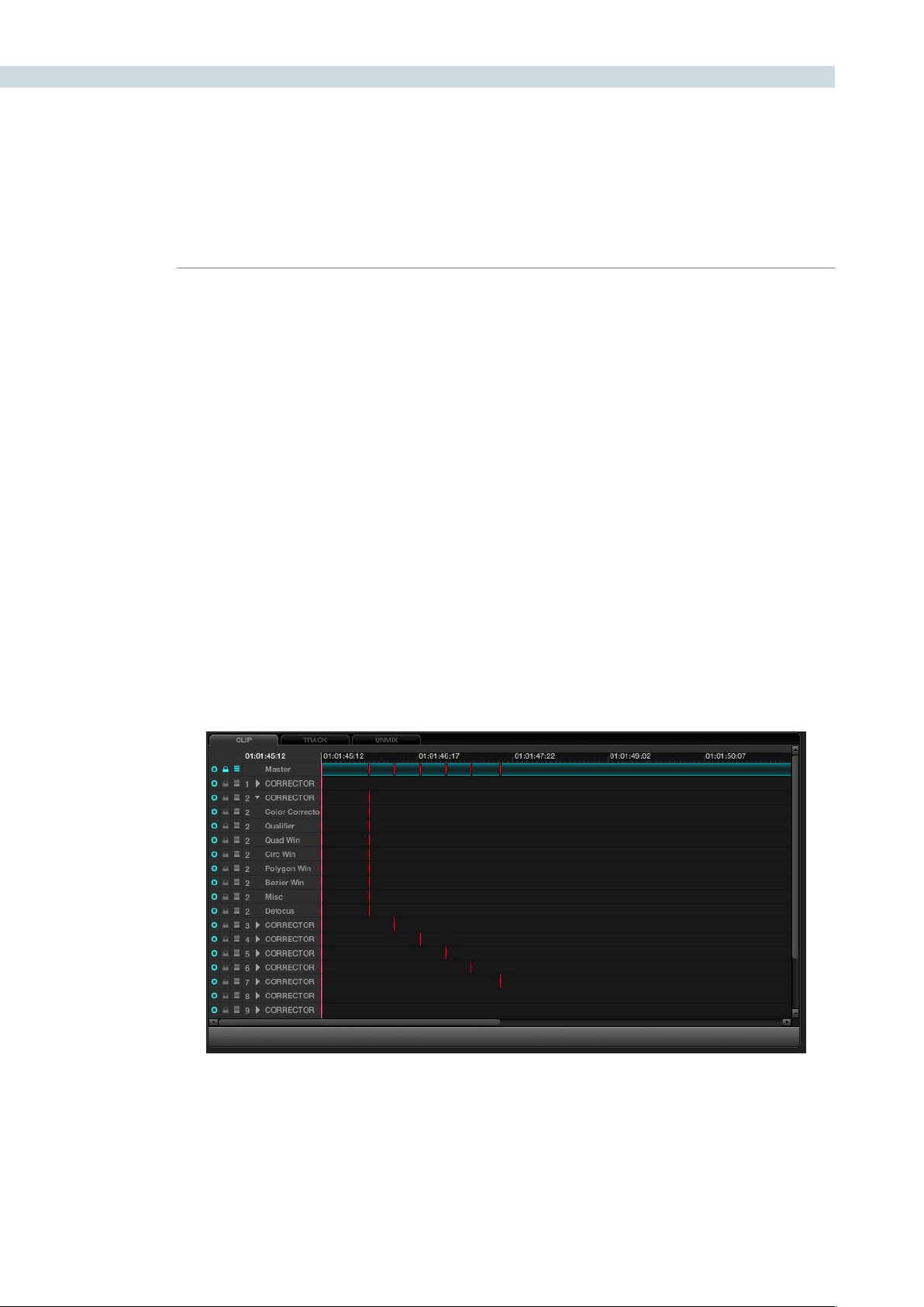
COLOR 286
On the bottom right of the Color screen is the Dynamics Timeline. This timeline displays and offers
control of keframed events such as dissolves or transitions of grades during a clip or for the whole
timeline. This display has also been referred to as the List Timeline or the Events Timeline. Principally, this
graphical display shows the all the events for every grade change for every clip, one clip or one track at
a time. The Node Graph display above the Dynamics Timeline also displays the Clip, Track, and Unmix
tabs in sync with the Dynamics Timeline.
There are three tabs in this section.
Clip: Once the timecode reaches the next clip, the correction within this clip will be displayed.
Track: This mode relates to the whole timeline and is useful when you wish to create an
overall color trim to all the graded material.
Unmix: Unmix is essentially the same as the Clip mode, however no effects such as dissolves
or speed changes will be displayed. Note: the Node Graph display above the
Dynamics Timeline also displays the Clip, Track, and Unmix tabs synchronized with
the Dynamics Timeline.
Many of the operations here are via the UI and a mouse, but there are number of display changes
automatically made in this area as each clip is graded and as the timeline plays. If for example, you wish
to insert a dissolve within a clip, this operation can be performed within the Dynamics Timeline display.
Dynamics Timeline
Dynamics Timeline
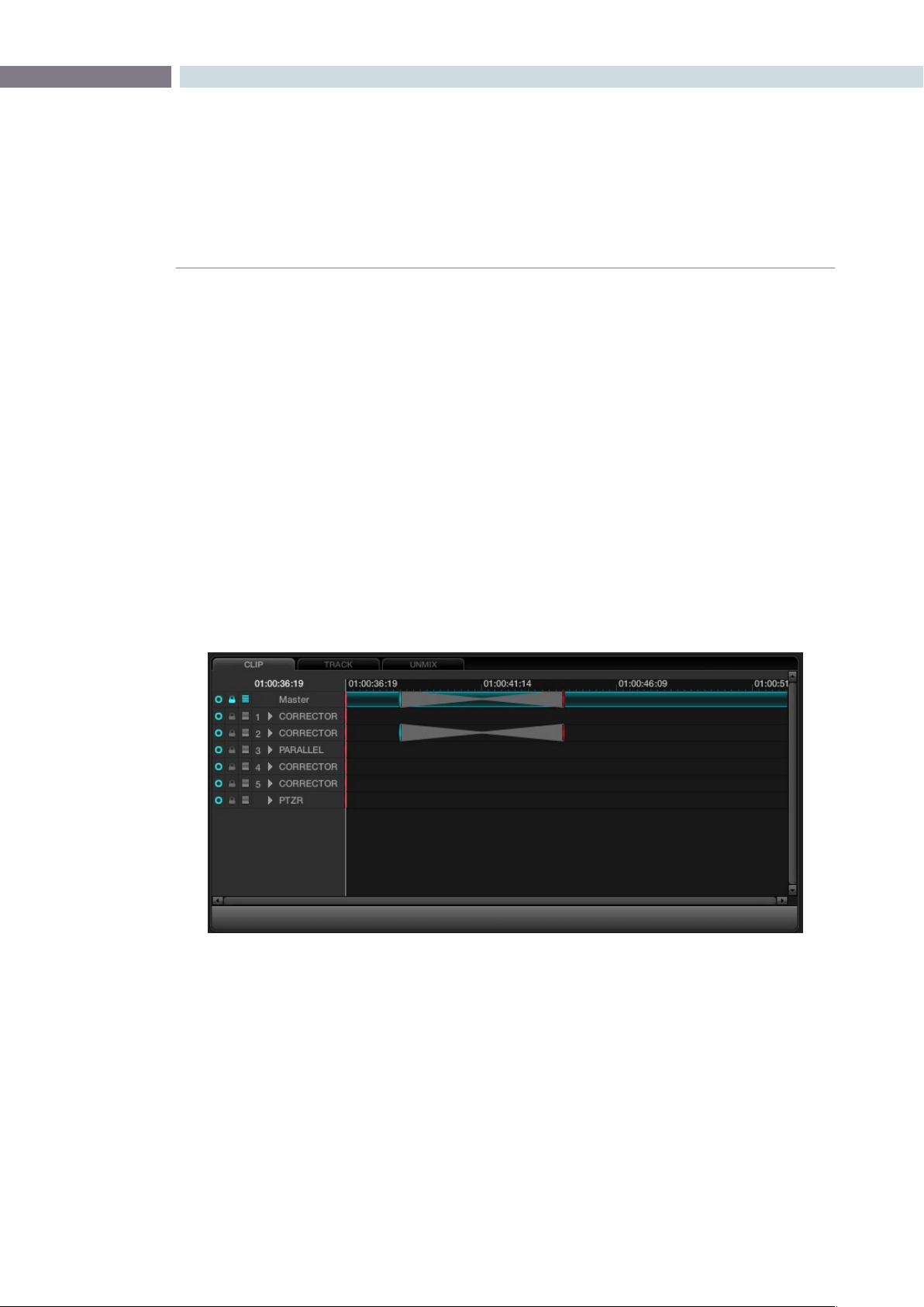
CHAPTER
COLOR
COLOR287
9
Dynamics Indicators
At the top of the tabs, on the left, the current timecode matches the timeline position. To the immediate
right is the clip, or track, timeline, and timecode display. You will see the first of what can be many lines
of information, with the first being the master channel with three icons to the left of the channel name
as indications of the selected state possible in the channels below.
Under the Master, each corrector node or mixer node will have an indication of grading changes and
atthebottomofthelistyouwillseethePTZRchannel.Thewhiteverticallinethroughallthechannels
indicates the current frame, matching the timecode, and within each channel display, markers will show
dynamic transition keyframes.
At the far left of the Dynamics Timeline display, for each of the channels, the radio button will indicate
thatthechannelisactiveorde-activated.ThismatchestheDaVinciResolveControlSurface‘Disable
Current’ key and also performs the same function as clicking on the left of the node number on the
NodeGraph.The‘Lock’functiondirectlytotherightwilllockanychangestothegradeforthischannel
when the padlock icon is activated. If you seem to be adjusting the grade and nothing is happening,
check this icon in case it is selected.
The next icon to the right indicates that the Auto Keyframing tool has been activated. When activated,
each time you adjust the grade the channel indicator will be automatically updated to reflect the
correction change. This mode is typically off. While useful, it can also be distracting to some people.
To the right of the Auto Keyframing icon you may see a channel number indicating the correction
channel (the node) to which this line of display refers. To the right of these, the arrow normally points
right,butifyouselectthearrowwithyourmouse,thecorrector(orPTZRchannel)willexpandtoshow
a number of more lines of grading and sizing parameters. Each is keyframable.
Marks are made for the individual channel elements, and with a large Node Graph this list can be quite
long. Every variable is captured here for every clip and stored with the Project metadata.
Dynamics Timeline
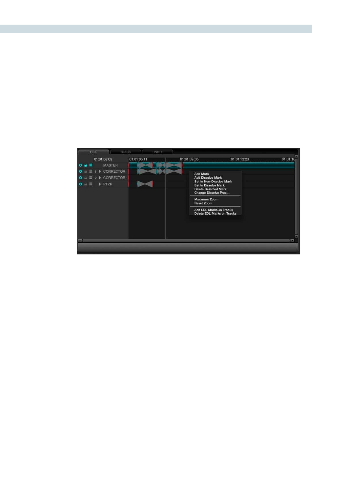
COLOR 288
Adding Dynamics
Dynamics can be added in a number of ways. With the UI, right mouse click and select the appropriate
function from the pull-down menu that appears within the Event Timeline display.
Add Mark:Willenteraneventmarkintothetimeline,orsimplypressthe‘Mark’
button on the DaVinci Resolve control panel and a mark will appear
in the Dynamics Timeline display.
Add Dissolve: Simply play the clip to the point where the dissolve should start
and right click select to add the dissolve mark. Then play the clip
to the point where the dissolve should finish and add Mark. The
dissolve will then appear within the Event Timeline display.
Set to Non-dissolve Mark: If you have an existing dissolve mark you can change it to a
standard mark
Set to Dissolve Mark: This will change an existing mark to a dissolve mark.
Moving a Mark: To change the position of an event or dissolve, simply highlight
the event by left mouse clicking on the event and then drag it to
the desired location.
Delete Selected Mark: To delete an event, left mouse click on the event in the Dynamic
Timeline display which will highlight this event. Then right mouse
clickandselect‘DeleteSelectedMark’fromtheoptions.
Change Dissolve Type: When right mouse clicking within the Dynamics Timeline display
andselecting‘ChangeDissolveType’fromthemenu,youcan
adjust the start and end profiles of a dynamic or dissolve event.
There are a number of different variations for the start and end
profiles available. The default values may be established within
the Configuration page.
Dynamics Timeline Right Click
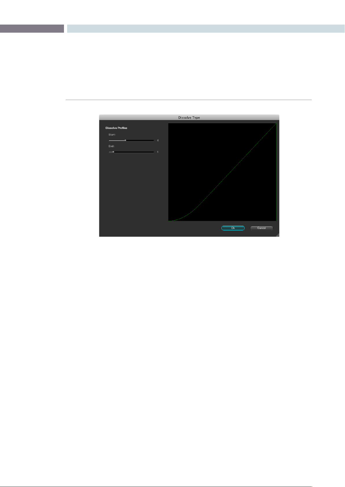
CHAPTER
COLOR
COLOR289
9
Render Cache Options
When working with dissolves from one clip to another, or complex corrections, you may want to
generate a Render Cache, as sometimes the two streams of full bandwidth images can not be played
or processed in real time. If you select the Cache D mode and play through the clip transition once, the
frame rate will play slower than normal the first time. Afterwards, the Cache file will be created and then
the clip will play at full speed.
There are four Render Cache Options.
Cache A: This will cache all material.
Cache D: This will cache only the dissolves.
Cache +: This will enable the background render cache process.
Cache U: This will cache a clip that has been flagged by the user in the Resolve Color
page Thumbnail display.
Youmayalsopre-renderalldissolveswithinaprojectbypressing‘Cntrl-R’whenintheCacheDmode.
This feature is very useful when you are playing a project for a client and don’t want to see any slow
downs in the system during image dissolves. The function will stop at the end of the timeline or when
youpress‘Stop.’
Dissolve Type

COLOR 290
Switching Between Conforms within the Color Page
To switch between sessions (i.e., EDLs) within the Color page, simply press the ’Mode’ button on the
DaVinciResolvecontrolsurfaceandthen‘SwitchSession.’OntheLegacy2KpanelusetheOrange
diamondbuttonandthen‘A/CMode’buttonontheDaVinciResolveKeyboardcontrolpanel.
The timeline will immediately change to the new session.
Scroll Mode
In the Color screen, there are various ways of copying grades into the current clip by recalling from
Memory, Gallery Stills, timeline thumbnail clip numbers, or scrolling through the clips.
The Thumbnail Timeline display provides one mechanism to allow the copying of grades into the current
clip by traversing reference clips and frames through the timeline.
The enhanced Scroll Mode is controlled on the trackball panel of the DaVinci Resolve control surface by
selectingthe‘Modes’buttonabovetheRHStrackballandthen‘ScrollMode.’Themodealsoprovides
backward panel support for the legacy 2K panels with deck control and soft knobs.
In addition to allowing you to select a reference clip via [Scene Number], [Prev Scene], [Next Scene],
andtheJogwheel.OntheLegacy2Kpanels,the[RedDiamond]+[Scroll/Deck]togglestheoption
to use the transport controls to traverse the reference clips in the thumbnail timeline in addition to the
soft buttons. (Default Off.)
ThePanelmenuscanbesettoScrollmodeafterpressingthe[Scroll/Deck]buttonontheJog/Shuttle
control panel. Exiting the Scroll Mode menu would bring the panel menu back to the Secondary menu.
On the thumbnail timeline, a thumbnail border highlight (yellow) indicate the current reference clip for
the scroll operation. While scrolling through the timeline, the reference clip stays visible in the thumbnail
timeline and is brought (cued) into visibility when the clip is out of the thumbnail view.
On the timeline, the current scrolled frame is indicated with a yellow line, which is different from the
current PlayHead cursor position (White line).
Scroll Controls
[Step Fwd] Step to next scene
[Step Rev] Step to previous scene
[Play] Plays (scrolls) forward through the scenes at 1 scene per second
[Rev] Play (scrolls) the scenes in reverse at 1 scene per second
[Fast Fwd] Shuttles (scrolls) forward through the scenes at 4 scenes per second
[Fast Rev] Shuttles (scrolls) reverse through the scenes at 4 scenes per second
[Slow Fwd] Shuttles (scrolls) forward through the scenes at 1 scene per 3 seconds
[Slow Rev] Shuttles (scrolls) forward through the scenes at 1 scene per 3 seconds
Other Color Screen Features


10
Viewer
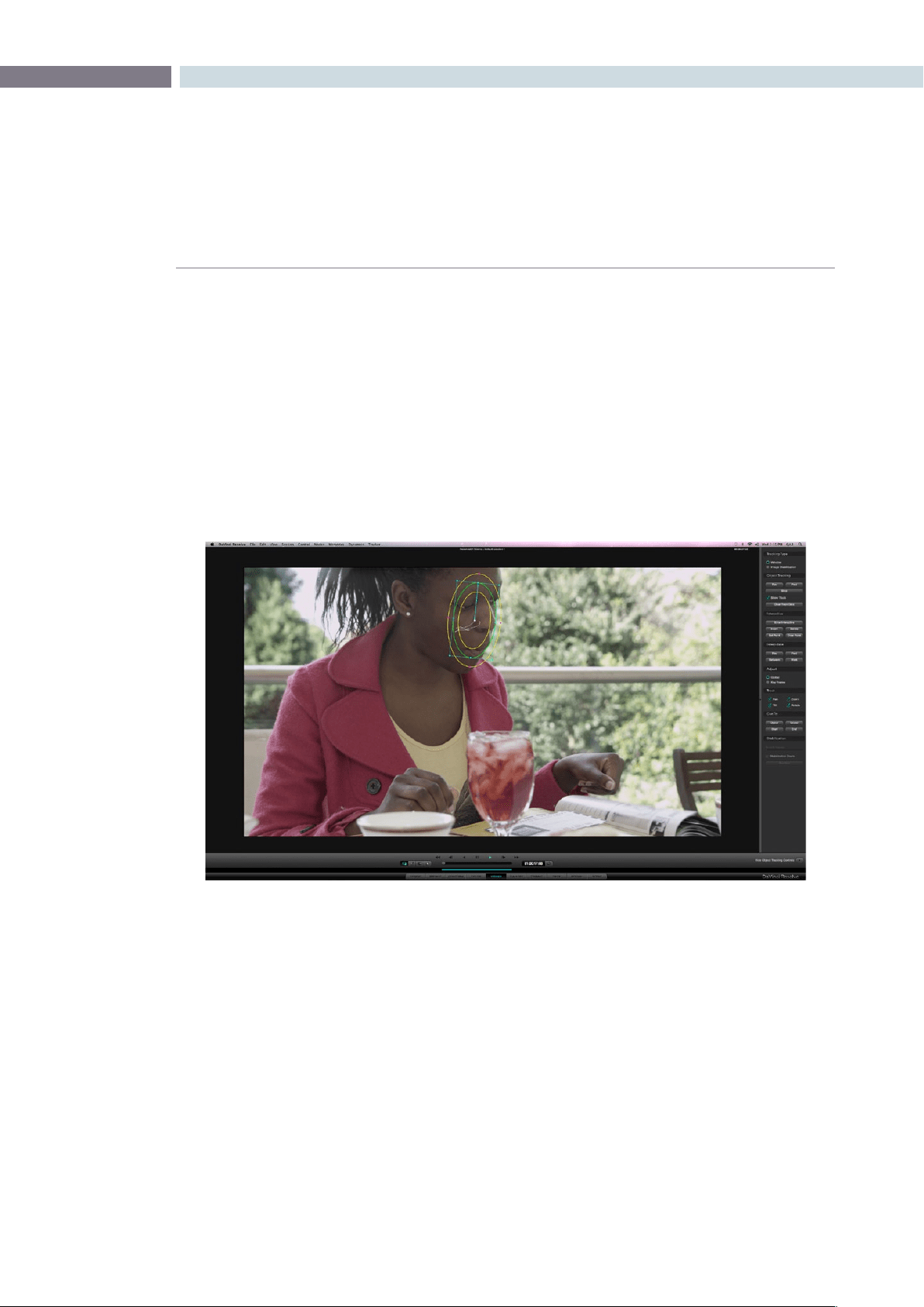
CHAPTER
VIEWER
VIEWER293
10
Viewer
The Viewer screen provides a full screen view of the current frame with transport controls, timecode
indications and other features as seen in the Color screen viewer display.
Youcanzoomevenfurtherintotheimagebyeitherusingthe‘+’and‘–’keysonthekeyboardorby
using the rotary center mouse button on the mouse. You may also reposition the image in the Viewer
by holding down the center mouse button and dragging the image to the desired position. To reset the
Viewersize,simplyrightmouseclickandselecteither‘Reset’or‘OriginalSize’fromtheoptionswithin
the pull-down menu.
There are two screen display modes within the Viewer. The main is a full screen display, as indicated
above. The second, which will be covered in detail later in this chapter, includes a right hand slide window
that provides controls for object tracking.
Viewer Page

VIEWER 294
Full Screen Viewer
At the top of the Viewer, in the center window bar, is the name of the Project and Session. To the left
of this is a GPU status display and the playback speed display in frames per second. The GPU status
indicates the percentage of use that the current color correction demands of the GPU. A full green
indication is good, indicating there is plenty of GPU headroom. As the GPU processing resources are
used by additional color correction, the green bars will reduce. A flashing red indication shows that
the GPU is unable to consistently process the correction in real time. Ultimately, as you add a greater
number of corrections, you will reach the real time limit of the GPU and DaVinci Resolve will play back
at a slower than selected speed.
There are a number of operational options in this situation to continue with the slower than real time
operation.Ifyouselect‘On-The-FlyProxy,’DaVinciResolvecangenerateproxysourceimagesinreal
time, which will allow the GPU sufficient headroom to process the image, or you can select Render
Cache to cache the clip.
This display will show either Record or Source timecode, Record or Source frame number, and, if available
in the DPX header, KeyKode. On the bottom right of the Viewer is the primary timecode display for the
clipbeingplayed.Justlikethetopdisplay,youcanchangetheinformationdisplayedbyclickingonthe
timecode display with the mouse to toggle the display between the five options, as indicated above.
To the right of the primary timecode display is the Clip Loop selection button. When enabled, the
current clip displayed in the timeline will turn blue so you can play the clip in a Loop mode.
The button on the left-hand side will select and deselect the PowerWindows cursors. The next button
will change the cursor into the Color Picker mode for selecting a specific color from the Viewer image.
When the third button is activated, the Gallery Wipe will be visible. The right button is used to activate
the interactive Dirt and Dust tool.
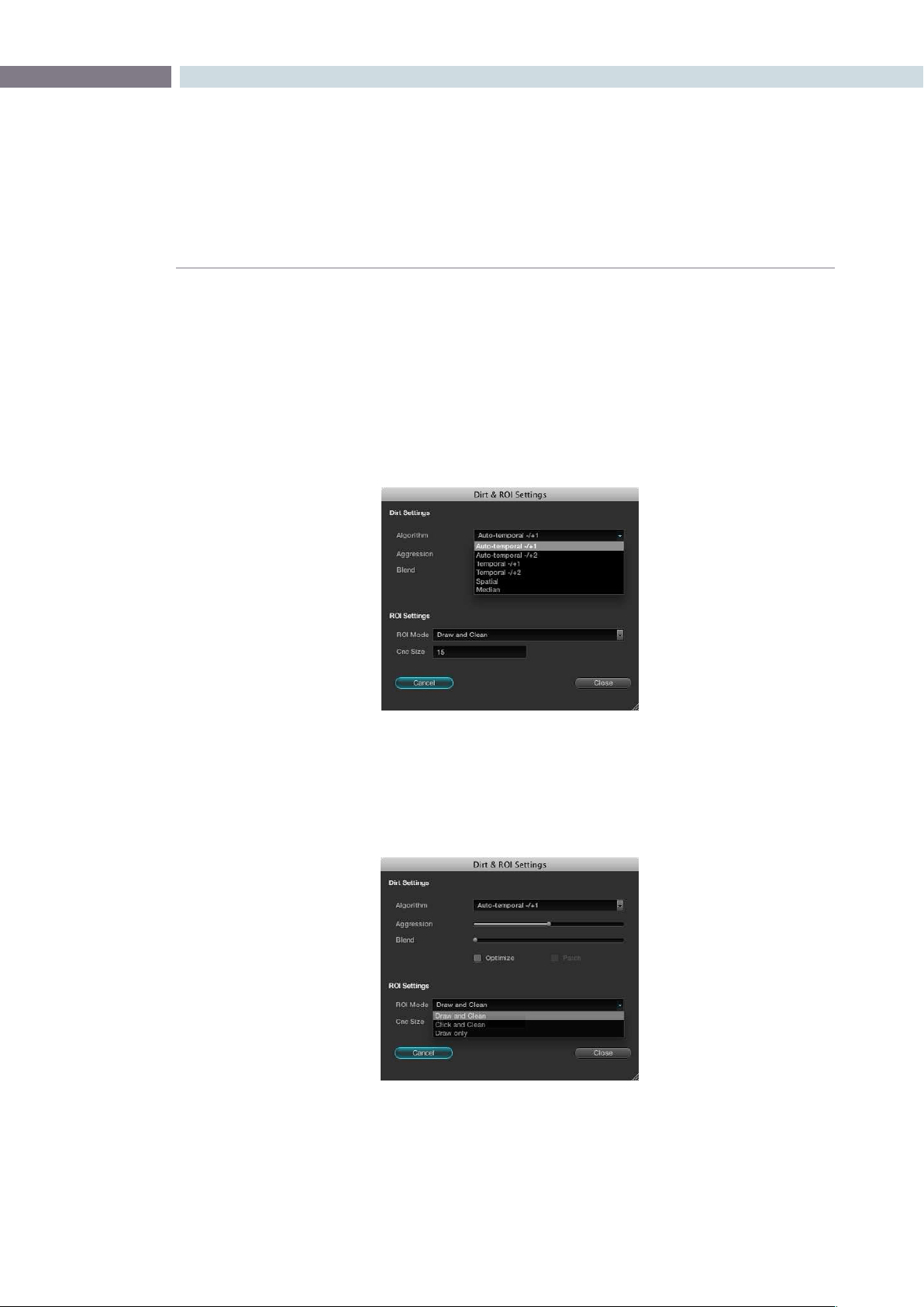
CHAPTER
VIEWER
VIEWER295
10
Interactive Dirt & Dust Removal Tool
DaVinci Resolve provides an interactive Dirt and Dust removal tool which can accessed be from either the
Viewer or Color pages by clicking on the Dirt Removal tool icon located at the left of the Viewer display.
Within the Dirt Settings section of the setup widget, you may adjust the Algorithm section to select the
filtration being used for the correction. There are also adjustments for the Aggression and Blend sliders,
depending on the degree of correction to be applied.
The ROI Settings allows you select the correction method. If you chooses the Click and Clean mode,
this will apply the correction for clicks on the object with the mouse. If the Draw and Clean mode is
selected, highlight the area with the mouse and the correction will be applied. If you are unhappy with
yourcorrection,select‘Undo’toreturntotheoriginalimage.
Dirt Settings
ROI Settings
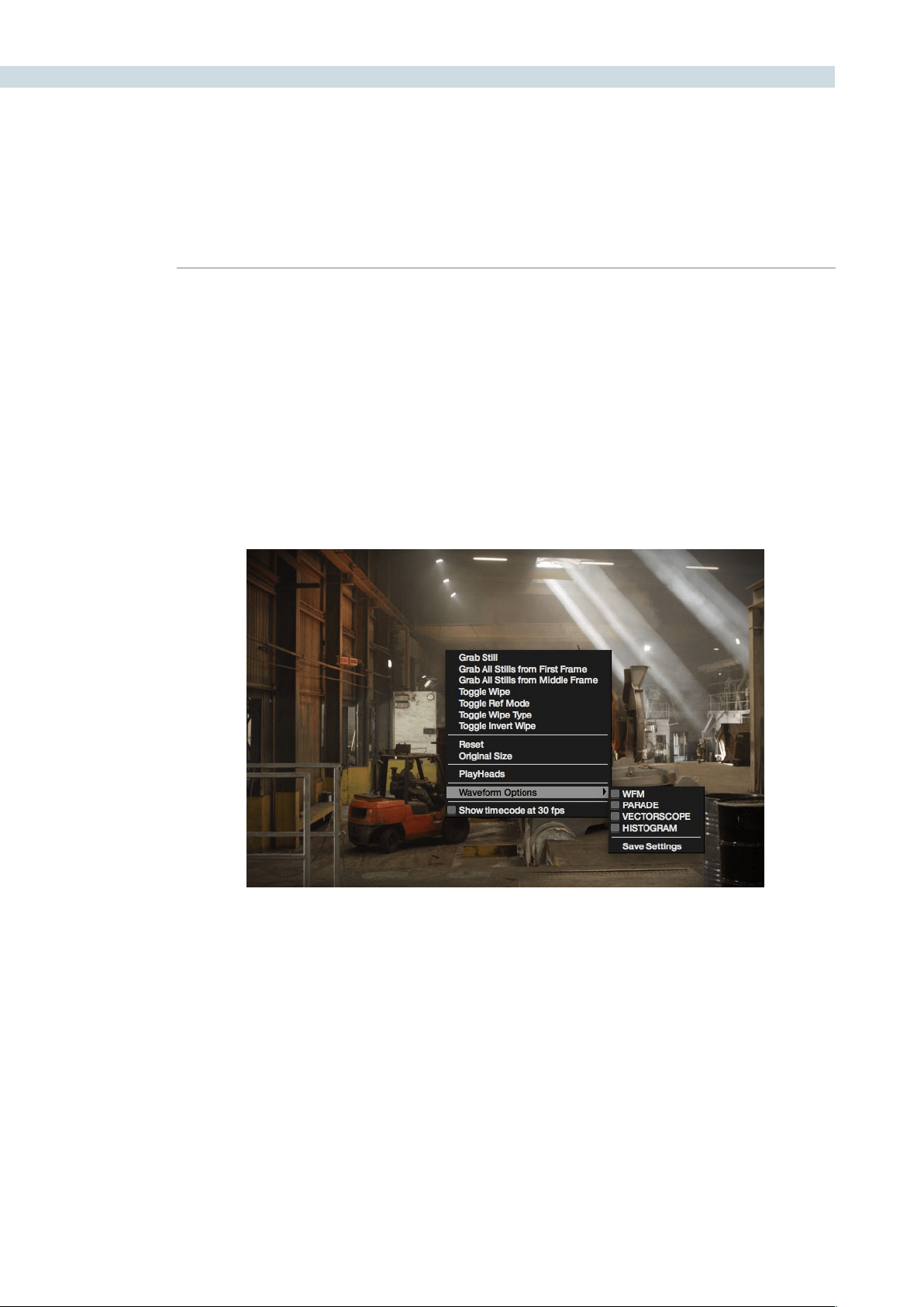
VIEWER 296
Viewer Window Options
There are a number of centre and right click mouse options for the viewer.
You may zoom in and out of the image within the Viewer by using a rotary control within the center
mousebuttonandalsozoominandoutoftheimagewithintheViewerdisplaybypressingthe‘+’and
‘–’keysonthecomputerkeyboard.Ifyouholddownthecentermousebuttonanddragthemouse,it
will move the image position within the Viewer display. To reset the Viewer display to the correct size
andposition,rightmouseclickwithintheViewerandselect‘Reset.’
If the user right clicks the mouse while it’s over the Viewer a pop-up window provides a number
of options.
Viewer Window Right Click Menu
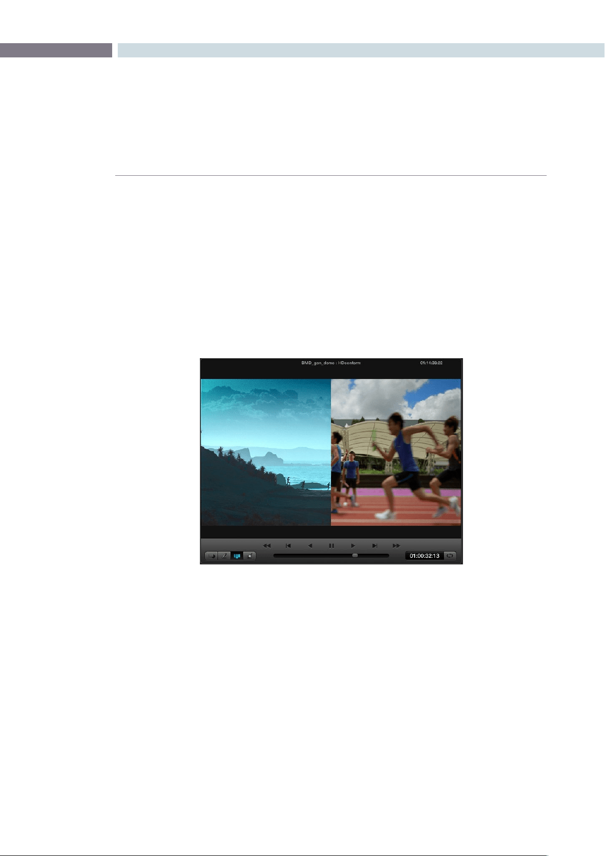
CHAPTER
VIEWER
VIEWER297
10
Viewer Stills Display
TherstsectionoftheserightclickoptionsrelatestoStills.‘GrabStill’willsimplygrabthecurrentframe
tomakeastillandplaceitintheGalleryStillsdisplay.‘GrabAllStillsfromFirstFrame’willgrabastillfrom
everycliponthetimelineusingtherstframeofeachclip.‘GrabAllStillsfromMiddleFrame’willperform
the same function, except use the middle frame of each clip as the source of the still. Once this is started,
it will work in the background and grab a still for each clip within the timeline. It is important to note that
once this procedure has started, it will continue until completed.
The Toggle Wipe selection will turn the wipe on and off. This function on the DaVinci Resolve panels is
called‘PlayStill.’TheToggleWipemodewillselecteithertocomparethecurrenttimelinecliptoeither
the Gallery Still, the matching offline frame or another clip on the timeline.
You can select another clip to wipe against by selecting the still on the Still, Memory, or PowerGrade
tab. Toggle Wipe Shape switches between vertical wipe, horizontal wipe, mix or a key or Alpha control.
Toggle Invert Wipe will swap the reference and current images in the Wipe display so you can see the
other side of the images.
The next section of the pop-up menu includes the Reset and Original Size options. Reset will set the
image to the normal display for the Viewer. Original Setting will display the image pixel-for-pixel so it is
usually for getting quick zooms to the source image size to look for imperfections in the original image..
Viewer with Play Still enabled
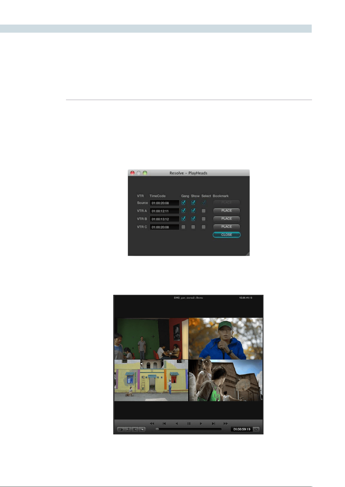
VIEWER 298
PlayHeads
The next section of the pop-up menu is the PlayHeads selection. Most commonly used to compare a
reference clip with others, playheads allow you to select and play up to four clips and display them at
the same time. Within the PlayHeads window you can set which playhead is attached to which clip.
Selectingtheclipsand‘Place’willlinkthecliptotheappropriateplayhead.Gangthemtogetherfor
synced playback. The ’Show’ checkbox will turn the display of the clip off and on.
Refer to the PlayHeads section of the Color chapter for more details on PlayHeads.
Playheads
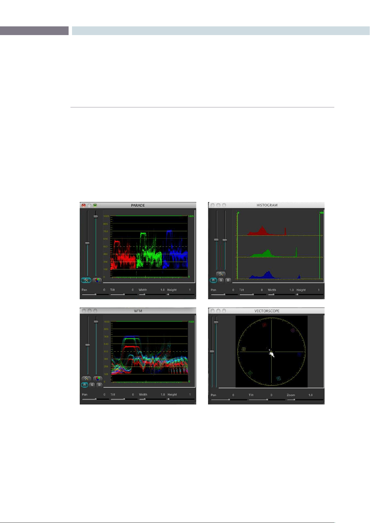
CHAPTER
VIEWER
VIEWER299
10
Waveform displays
DaVinci Resolve offers a number of built-in waveform displays, all of which work at the native resolution
of the system rather than at the video standard selected for clip playout. This means you can see the
full data range of the source image with the correction applied, regardless of which video standard in
which you master.
The display option are: Waveform, Parade, Vectorscope, and Histogram. They allow you to monitor
the levels of the correction that are being applied to the image, and within each display there are the
controls to vary the brightness of the scale and information displayed.
Show Timecode at 30 fps
The final item on the list of options is a checkbox to show the timecode in the timecode display at 30 fps.
This is used to show timecode as it would appear on tape in a 2:3 pull up mode from a 24 fps project.
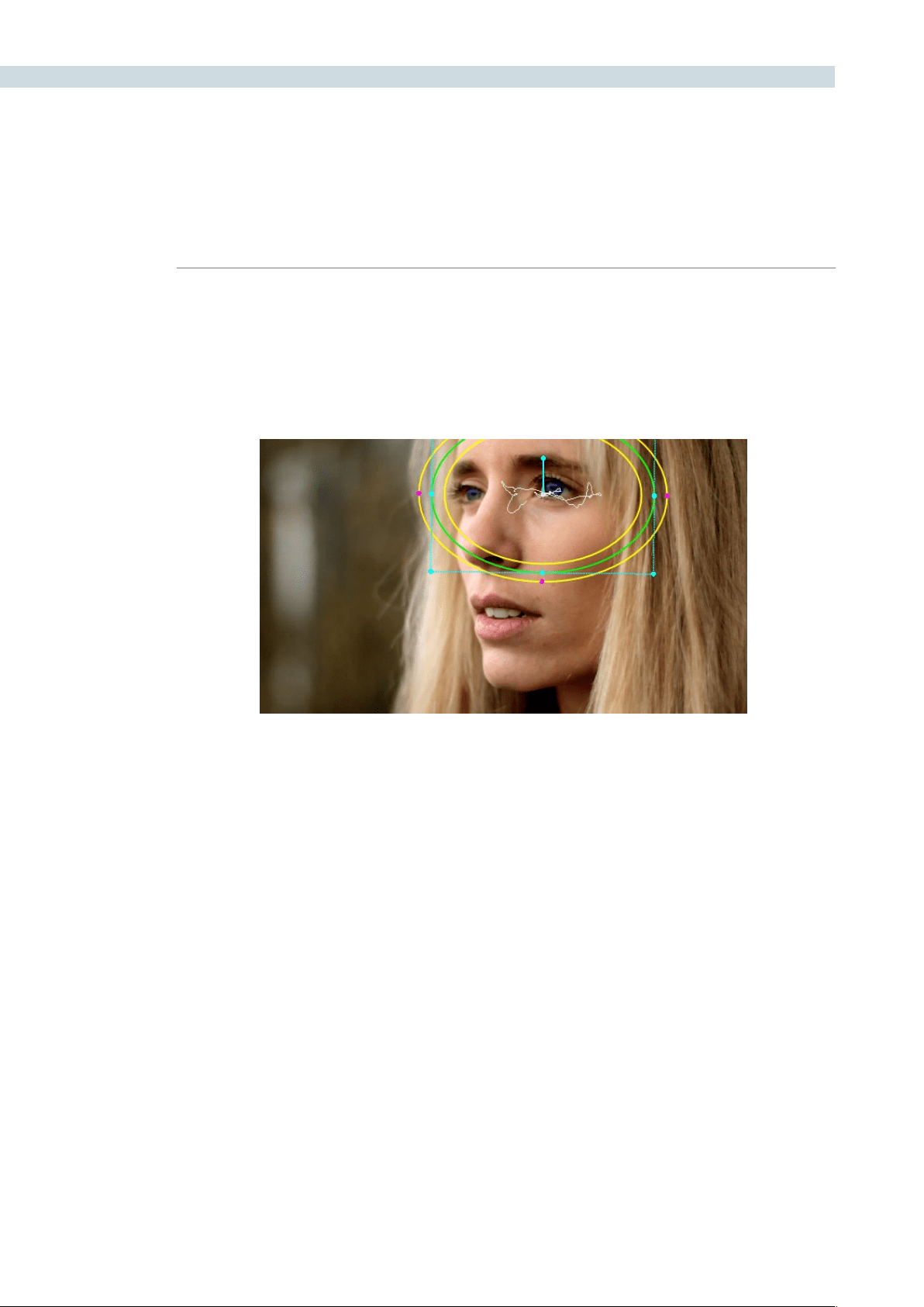
VIEWER 300
DaVinci Resolve has an incredibly simple, yet powerful, object tracker that allows you to quickly and
accurately track any Power Window (Circular, Linear, Polygon, or Power Curve) to follow any moving
feature. This avoids the need to manually use dynamics (keyframes) to animate a window’s position.
In particular, you can use the tracker to match a window’s position to either foreground or background
elements that move within the frame.
Simple Tracking Using the Tracker Menu
The simplest way to track a feature using a Power Window is to use the commands found in the Tracker
menu. These commands include:
Track Forward (Command-T): Tracks a Window to a feature from the current position of the
playhead forward, ending at the last frame of a clip.
Track Reverse (Option-T): Tracks a Window to a feature from the current position of the
playhead in reverse, ending at the first frame of a clip.
Track Stop: Interrupts any track. This is useful for letting you cancel a long
track that goes wrong. The Stop button of a control surface
stops tracking as well.
Most window tracks are easy to accomplish using these three commands.
Object Tracking and Image Stabilization
A power window tracking a women’s eyes; the motion path resulting from the
track is shown as the wiggly white line
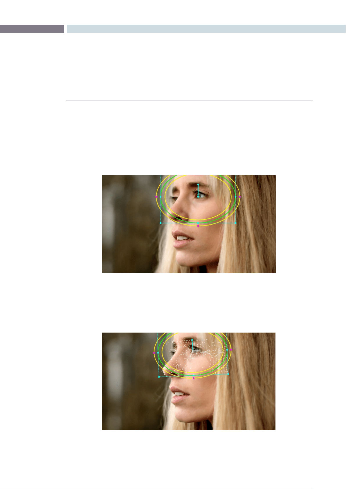
CHAPTER
VIEWER
VIEWER301
10
To track any Power Window to match a moving feature within the frame:
1: Move the playhead to the frame of the current shot where you want to begin (you
don’t have to start tracking at the first frame of a shot).
2: Turn on any window, and adjust it to surround the feature you want to track.
Typically, you’ll have done this anyway, for example, framing someone’s moving face
with a Circular Window to lighten their highlights.
3: Choose Tracker > Track Forward (Command-T) or Tracker >Track Reverse (Option-T) to
match the motion of the Window to the subject you’ve isolated.
Resolve automatically opens the Viewer page, places a series of tracking points within
the window you’ve created, and performs the track from the current frame; forward to
the last frame or in reverse to the first frame.
Object tracking in progress, tracking points are automatically placed over
trackable features of the image
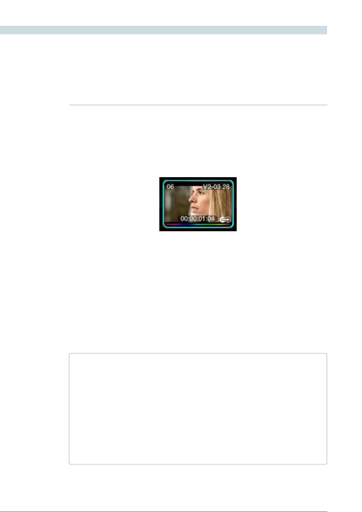
VIEWER 302
Resolve analyzes a cloud of tracking points that follow the vectors of every trackable group of
pixels within the window you’ve created, and the results are fast and accurate. After tracking, the
window you’ve placed automatically moves, resizes, and rotates to match the motion of the feature
you’re tracking.
Once a clip has tracking data applied to one of its windows, a small tracking icon appears within that
clip’s icon in the thumbnail timeline.
Simple Ways of Working With Existing Tracking Data
If you find that you don’t like a track you’ve made, you can simply move the playhead back to the frame
where you’d like to redo tracking, and start all over again. New tracking data always overwrites old
tracking data.
If there’s a portion of a shot that’s you haven’t tracked (for example, you started tracking at a later frame,
or you ended tracking prior to the end of the shot), then the Window you’re tracking remains wherever
it was at the first or last frame that was tracked. If you want to fill in these gaps, you can always move
the playhead to the first or last frame that was tracked, and then use the Track Reverse or Track Forward
command to track the rest of the frames in that shot.
Tips For Better Tracking
In general, you’ll achieve better results if you track features using Windows with no edge
softness. You can add softness later, after the track has been accomplished.
In situations where a feature changes shape in such a way as to confuse the tracker, you can
try tracking a smaller part of the feature by using a smaller window. Once you’ve achieved a
successful track, you can resize the Window as necessary, and it will have no effect on the
track that’s already been made.
Lastly, if you’re tracking a feature that moves behind something onscreen and disappears for
the rest of the shot, there’s an easy way to avoid having an awkward window sitting in the
middle of the scene. You can use dynamics/dissolve marks (keyframing) to animate the Post
Mixing Gain slider (in the Key tab of the Color page) to fade from the correction’s full strength
of 1.0 down to 0, the value at which the correction disappears, along with the window itself.
A tracking icon in bottom-right corner of the Thumbnail
timeline shows that clip has been tracked
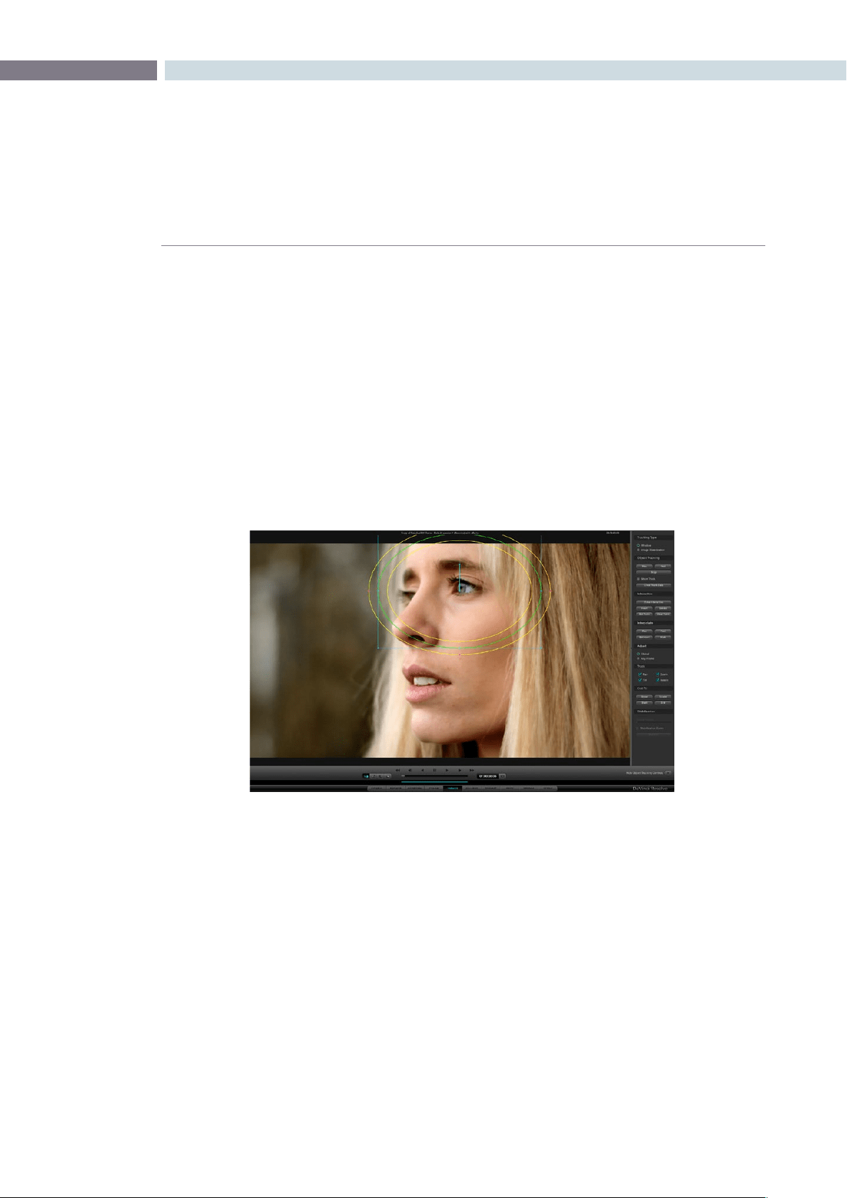
CHAPTER
VIEWER
VIEWER303
10
Combining Tracking and Dynamics (Keyframing)
Object tracking and dynamics used to animate windows can be easily combined. For example, you’ll
typically use object tracking to make a window follow the position and orientation of a moving feature,
but you can add dissolve marks to the window track of the correction in the Color page with which to
alter its size and shape to better conform to the feature’s changing form.
For more information on dynamics and dissolve marks, see XREF.
Object Tracking Controls on the Viewer Page
Occasionally, you’ll run into a shot that doesn’t quite track well enough using the Tracker menu’s simple
controls. In these cases, the Viewer page provides the complete set of object tracking controls that can
be used to modify tracking operations in different situations.
To open the tracking controls:
Open the Viewer page, and click the Show Object Tracking Controls button at the
lower righthand corner.
The Object Tracking Controls are divided into seven groups.
Tracking Type
Two radio buttons let you choose between Window mode (for matching a Window to the motion
of a feature in the frame), and Image Stabilization mode (for subduing unwanted camera motion,
covered later).
Viewer screen with Object Tracking controls at right
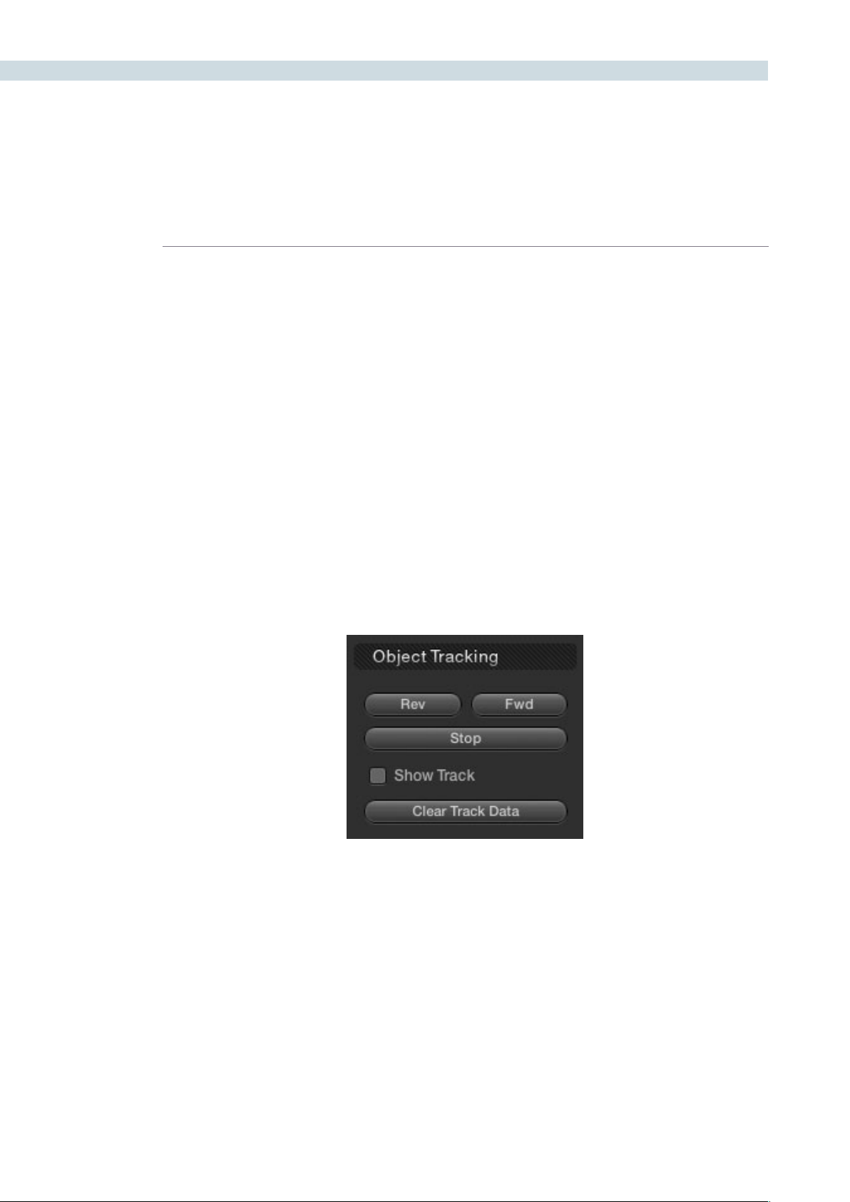
VIEWER 304
Object Tracking
The Object Tracking controls provide all of the basic tracking functions. Some of these are mirrored
within the Tracker menu.
Rev button: Initiates tracking from the current frame in reverse, ending at the
first frame of the clip.
Fwd button: Initiates tracking from the current frame forward, ending at the
last frame of the clip.
Stop button: Stops tracking (if you’re fast enough to click this button before
tracking is actually finished).
Show Track checkbox: Turn this checkbox on to show the motion path produced by
the tracking you’ve done.
Clear Track Data: Lets you delete tracking data for the current clip. When you
click Clear Track Data, a Clear Tracking window appears with
four checkboxes that let you choose which window, within the
current clip, to clear tracking data for. By default, every checkbox
is turned on.
Controls in the Object Tracking group
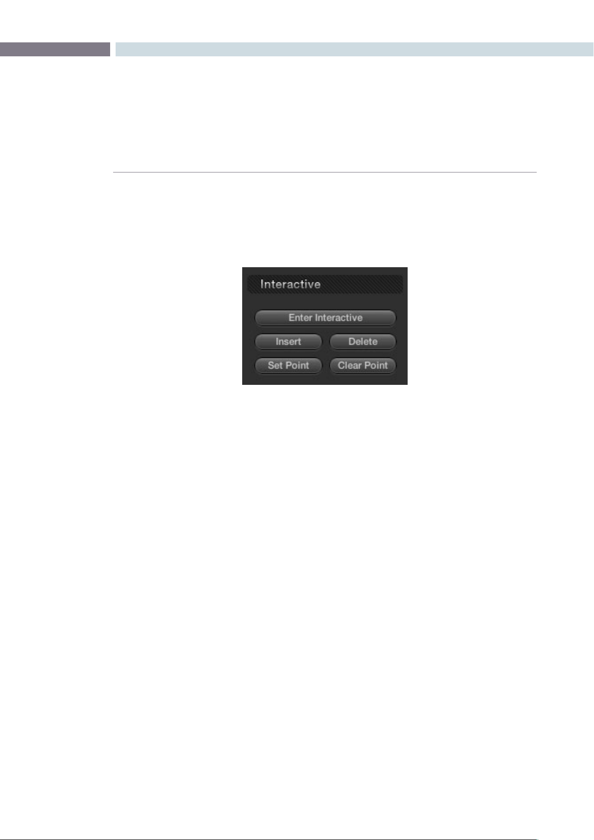
CHAPTER
VIEWER
VIEWER305
10
Interactive
The Interactive controls let you make manual changes to the automatically generated tracking
point cloud that Resolve creates, so you can try different ways of obtaining better tracking results in
challenging situations.
Enter Interactive/Exit Interactive:
Turns the Interactive tracking mode on and off. When you enter
Interactive mode, you can manually alter the point cloud that
Resolve uses to track the feature within the current window.
When you exit Interactive mode, your manual changes to the point
cloud are eliminated, and Resolve once again uses automatically
placed point clouds to do all tracking.
Insert: Lets you add tracking points to whatever trackable features exist
within a bounding box that you’ve drawn. Inserted tracking points
are automatically placed based on trackable pixel groups.
Delete: Eliminates all tracking points within a bounding box that
you’ve drawn.
Set Point: Lets you use the cursor using the DaVinci Resolve control surface,
to manually place individual tracking points, one by one, with
which to track a feature. If there is no trackable pixel group at the
coordinates where you placed the cursor, a tracking point will be
placed at the nearest trackable pixel group.
You must place at least two tracking points at different pixel
groups to track rotation, and at least three to track zoom.
Clear Point: Eliminates all tracking points from the clip.
For more information, see “Using the Interactive Tracking Controls” later in this section.
Controls in the Interactive group
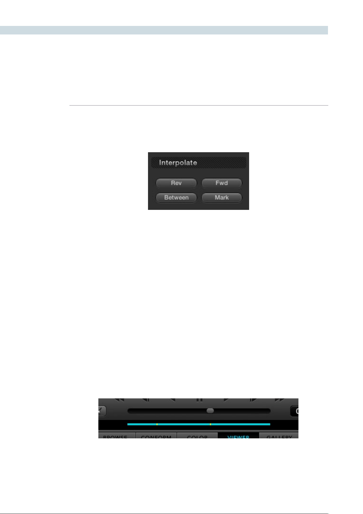
VIEWER 306
Interpolate
The controls in the Interpolate section provide ways of dealing with occlusions, or objects that temporarily
obscure features that you’re tracking.
By marking a hole the middle of two successfully tracked sections of a clip, you can interpolate a motion
path to fill the gap so that the vignette moves smoothly from the point where tracking is lost to the
point where tracking is found once again. These features require the tracker to be in Key Frame mode;
see the Adjust section below.
Rev: After using the Mark button to specify the beginning of a gap in
tracking data, you can move the playhead to the last frame of the
gap and click Rev to interpolate a motion path to fill the gap.
Fwd: After using the Mark button to specify the end of a gap in tracking
data, you can move the playhead to the first frame of the gap and
click Fwd to interpolate a motion path to fill the gap.
Between: After using the Mark button to specify both the beginning and
end of a gap in tracking data, click Between to interpolate a
motion path to fill the gap.
Mark: Lets you mark the beginning, end, or both of sections of a clip
where a feature being tracked is hidden. Once a clip has been
marked in the Viewer, you can use the Rev, Fwd, or Between
buttons to interpolate an animation motion path to fill the gap in
tracking data. Viewer marks appear as vertical yellow lines in the
tracking bar underneath the transport controls
For more information, see “Using the Interpolate Commands” later in this section.
Controls in the Interpolate group
Viewer Marks placed within the Tracking bar of the Viewer
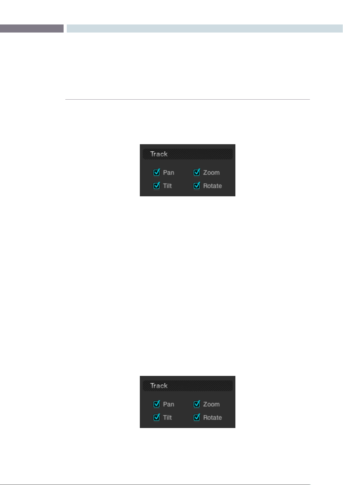
CHAPTER
VIEWER
VIEWER307
10
Adjust
Two radio buttons let you set how manual adjustments to the position of tracked windows affect the
overall track.
Global: In this default mode, changes you make to the position of a
window are globally applied to the entire track. In other words,
if you track a feature, and then move the window, the window
moves along a motion path that’s consistently offset from the
original track for the duration of the clip. Use this mode if you’re
happy with the track, but you want to modify the window’s
overall shape and position relative to the motion path it’s
following.
Key Frame: In this mode, changes you make to the position of a window
are only applied to the current frame. This mode is required for
using the Interpolate commands explained above. However,
Key Frame mode is also useful for making corrections to badly
tracked frames, or for manually adjusting window position frame-
by-frame to cover untrackable sections ifthe Interpolate controls
aren’t capable of producing an acceptable result.
Track
A series of four checkboxes let you turn on and off which transforms you’d like motion tracking to
automatically apply to the window. These checkboxes also let you choose which transforms to analyze
when using Image Stabilization and are covered in a later section.
Options in the Adjust group
Options in the Track group
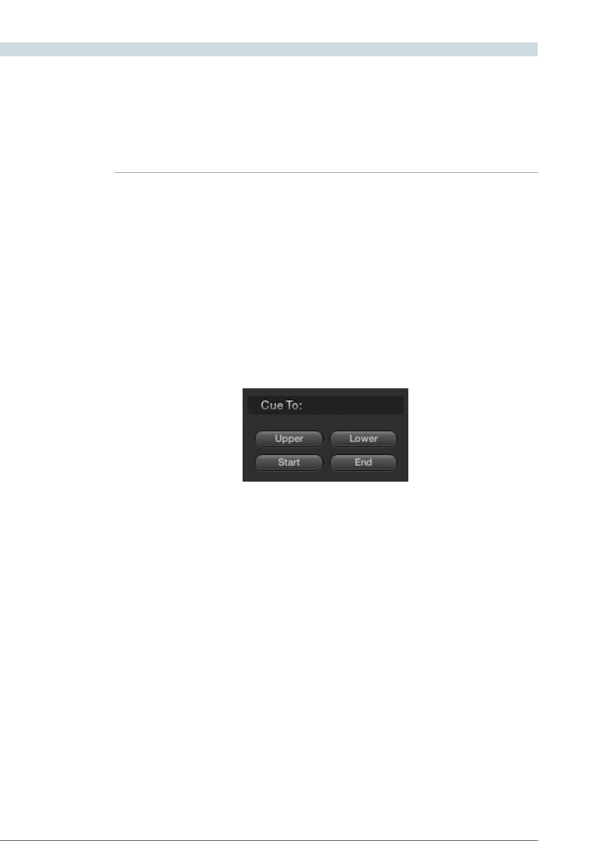
VIEWER 308
These checkboxes must be selected before you perform a track or stabilization operation in order to
restrict the transforms that are used. Once tracking or stabilization has been done, disabling these
checkboxes does nothing to alter the result. To make changes, you need to enable or disable the
necessary checkboxes first, and then re-analyze the clip.
Pan: Enables tracking of horizontal position.
Tilt: Enables tracking of vertical position.
Zoom: Enables tracking of size.
Rotate: Enables tracking of orientation.
Cue To
The Cue To buttons allow you to quickly navigate the playhead to different frames of the current clip
while setting up different tracking operations.
Upper: Jumpstheplayheadtothefarthestmarktotherightiftwo
marks have been placed.
Lower: Jumpstheplayheadtothefarthestmarktotheleftiftwomarks
have been placed.
Start: Jumpstheplayheadtotherstframeofthecurrentclip.
End: Jumpstheplayheadtothelastframeofthecurrentclip.
Stabilization
These controls are disabled while Tracking Type is set to Window. The Stabilization features are discussed
in a following section.
Controls in the Cue To group

CHAPTER
VIEWER
VIEWER309
10
Object Tracking Workflows
The next few sections will illustrate how to use the various groups of controls in practical situations.
Using the Interactive Tracking Controls
Interactive Object Tracking mode lets you manually remove or add tracking points in order to
improve tracking performance in situations where the automatic image analysis in Resolve provides
unsatisfactory results.
For example, you can delete tracking points within a window that correspond to overlapping features
you don’t want to track. Supposing a car that you’re tracking drives by a sign that partially obscures the
car. Without intervention, the Power Curve that’s isolating the car will deform improperly when the car
moves through and away from behind the sign.
Using the Interactive mode, we can delete the tracking points that correspond to the sign we don’t want
to track, improving the result.
To eliminate specific, unwanted tracking points from a track:
1. Open the Viewer page, and click Show Object Tracking Controls.
2. Click the Enter Interactive button
3. In the Viewer, drag a box around the tracking points you want to eliminate.
4. Click the Delete button, or press D.
The points within the selection area are deleted.
5. Now, while Interactive Tracking mode is still enabled, click Fwd or Rev to track the
subject without including the points you just deleted.
6. Once you’re finished tracking, click the Exit Interactive button.
Note: If you delete tracking points and then exit interactive mode without performing a new track first,
new tracking points will be automatically added to replace those you deleted.
In another interactive tracking example, you may sometimes run into situations where you want
to eliminate all automatically placed tracking points altogether, placing your own in specific regions of
the image.
To eliminate specific, unwanted tracking points from a track:
1. Open the Viewer page, and click the Show Object Tracking Controls button at the
bottom righthand corner underneath the Viewer.
2. Click the Enter Interactive button.
3. Click Clear Point to eliminate all tracking points from the image.

VIEWER 310
4. Drag a box around the area where you’d like to add new tracking points, then click the
Insert button, or press I.
New tracking points are automatically added within the box you’ve drawn to whichever
features are appropriate for tracking. If no appropriate tracking features can be found,
no points will be added.
While in Interactive Object Tracking mode you may also choose to add tracking points one by one.
To add a single tracking point:
1. Open the Viewer page, and click the Show Object Tracking Controls button at the
bottom righthand corner underneath the Viewer.
2. Click the Enter Interactive button.
3. Using your control surface, activate the cursor, move it to the area of interest, and
thenpressthe‘SetPoint’buttonwithintheTrackerwindow.Thiswilladdthetracking
pointattheselectedcoordinate.Clickthe‘ExitInteractiveMode’buttontorevertto
normal operation.
Using the Interpolate Controls
Sometimes you may want to interpolate a Power Window between two points within a clip. This is
primarily important in situations where features that have obscured the feature you’re trying to track
cause gaps in the tracking information for a clip.
To interpolate a motion path to fill a gap between two tracked sections of a clip:
1. Move the playhead to the first trackable frame of the moving feature you’re correcting,
and create a Power Window that surrounds it.
2. Use Track Forward to track the feature as far as you can before it becomes obscured
behind something else in the frame.
3. When the Power Window stops tracking the feature, stop the track by pressing the
stop button of your control surface.
4. Open the Object Tracking Controls in the Viewer page.
5. Click the Key Frame radio button to change the Adjust mode. This is an important step.
6. Move the playhead to the frame where the feature you’re tracking reappears from
behind the occlusion, then drag the window so that it once again overlaps the feature.
7. Use Track Forward to continue tracking the feature until the end of the clip. Alternately,
you could have started from the end of the clip and used Track Reverse to track the
feature as far as possible, if that makes it easier.
Now that you’ve identified the gap in your tracking data for this clip, it’s time to set up
the interpolation.

CHAPTER
VIEWER
VIEWER311
10
8. Do one of the following:
•Movetheplayheadtothelasttrackedframeinthersthalfoftheclip,andclickMark.
Then move the playhead to the first tracked frame of the second half of the clip, and
click Mark. With two yellow marks appearing in the Tracking bar, click Between.
•Movetheplayheadtothelasttrackedframeinthersthalfoftheclip,clickMark,then
move the playhead to the first tracked frame of the second half of the clip and click
Interpolate Rev.
•Movetheplayheadtothersttrackedframeinthesecondhalfoftheclip,clickMark,
then move the playhead to the last tracked frame of the first half of the clip and click
Interpolate Fwd.
No matter which method you use, a motion path is automatically interpolated to fill
the gap in between the clip’s two successfully tracked sections.
Another common situation is when a feature starts off-screen and then moves onscreen, such as a
person walking or a stationary feature that moves when the camera pans). While you can track the
feature as long as it’s fully within the frame, once it starts to move offscreen, you may lose your track,
and the window will be stuck at an awkward position onscreen even though the feature it’s supposed
to be correcting is gone.
You can use Resolve’s Interpolate features to solve this problem.
To manually set a new offscreen starting position at the beginning of a clip from which to
interpolate to a successful track:
1. After performing the initial track, open the Object Tracking Controls of the Viewer page,
and click Key Frame to change the tracking mode.
2. Move the playhead to the very first frame of the clip and move the window to the most
logical position, for the feature you’re tracking, to have moved to.
3. Click Mark.
4. Move the playhead to the first successfully tracked frame of the feature.
5. Click Interpolate Rev to interpolate a motion path from the first tracked frame, in
reverse, to the mark you made in step 3.
At this point, playing through the clip from the beginning results in the window moving
smoothly from the offscreen position through the rest of the track.
This same technique works for features that go offscreen at the end of a clip by using the Interpolate
Fwd button to interpolate from the last successfully tracked frame to a manually repositioned offscreen
window that has been marked at the last frame of the clip.
Since the Interpolate feature generates a smoothly linear motion path, it may not work if you’re tracking
an irregularly moving feature that becomes obscured. In these cases, you have the option of manually
tracking a window to fit the likely trajectory of the hidden feature, frame by frame.

VIEWER 312
To manually reposition or track a window that can’t be interpolated properly:
1. Open the Object Tracking Controls of the Viewer page, and click Key Frame to change
the tracking mode.
2. Move the playhead to the last frame of the clip that was successfully tracked.
3. Move the playhead frame by frame, adjusting the position of the window at each frame
to move along with the feature that you’re trying to track.
Continue adjusting the window frame by frame until you’ve reached the end of the
clip, or reached the end of the gap in tracking data so that the window is now at the
beginning of the next successfully tracked section of the clip.
This technique may not be fun, but it’ll get the job done in a pinch.
Image Stabilization
The Image Stabilization option of the Object Tracking controls lets you smooth out or even steady
unwanted camera motion within a clip. The analysis is performed in such a way as to preserve the motion
of individual subjects within the frame, as well as the overall direction of desirable camera motion, while
correcting for unsteadiness.
Image stabilization in DaVinci Resolve consists of three steps. First, you analyze the clip. Second, you
choose the Stabilization settings you want to use. Third, you click Stabilize to calculate the result.
As with Object Tracking, you can choose which aspects of motion to stabilize, but this must be done
before you do the initial image analysis.
Stabilization Controls
There are three controls in the Stabilization group:
Smooth Frames slider: Lets you choose how much stabilization to apply to the clip.
Lower values allow more of the original camera motion to show
through, while higher values lock the shot off more aggressively.
0 disables stabilization altogether.
Stabilization Zoom checkbox: When turned on, the image is resized by a large enough
percentage to eliminate the black edges that are the result of
repositioning the image in order to eliminate unwanted camera
motion. The higher a value Smooth Frames is set to, the more
Resolve will need to zoom into an image to eliminate these
black bars. If you turn this off, the image is not zoomed at all,
and whatever black bars intrude into the image are output along
with the image, on the assumption that you’ll have dedicated
compositing artists deal with eliminating these black edges in a
more sophisticated manner.

CHAPTER
VIEWER
VIEWER313
10
Stabilize: After you’ve tracked the clip and adjusted the previous two
controls, you need to click Stabilize to calculate the resulting
effect on your clip. Whenever you make changes to the Smooth
FramessliderandStabilizationZoomcheckbox,youneedtoclick
Stabilize to recalculate the result to your clip.
Using Stabilization
Image stabilization in DaVinci Resolve is easy, but you need to follow a specific series of steps for it to
be successful.
To stabilize an image:
1. Open the Object Tracking Controls of the Viewer page, and click Image Stabilization.
The Stabilization controls become enabled, while the Interpolate, Adjust, and Cue To
controls become disabled.
2.TurnoffanyoftheTrackcheckboxes(Pan,Tilt,Zoom,Rotate)thatcorrespondto
transform dimensions you don’t want to smooth.
3. Click Fwd to track the clip forward, or Rev if you’d rather start from the end of the
clip and work in reverse.
This analyzes the clip, but no stabilization is applied yet.
4. Increase the Smooth Frame slider setting to reflect the amount of stabilization
you want.
5. Choose how you want the edges of the stabilized clip to be handled:
•IfyouwantResolvetozoomintotheimageasmuchasisnecessarytopreventblack
edges from intruding into the frame as a result of repositioning the image in order
tosteadycameramotion,thenturnontheStabilizationZoomcheckbox.(it’son
by default)
•Ifyouwanttoleavethescaleoftheimagealone,allowingblackedgesto
intrudeinto the frame so that you can have an effects artist deal with filling in these
holes at a later time (without the need to zoom in), then turn off the Stabilization
Zoomcheckbox.
6. With all of these controls adjusted, click Stabilize.
The clip is immediately transformed to apply the amount of stabilization you
selected via the Smooth Frames slider.
7. Play the clip and examine the stabilization effect. If you need to make any changes,
choose a new Smooth Frames value, then click Stabilize.
Any time you change any of the Stabilization parameters, you need to click Stabilize
to recalculate the resulting transform to your clip.

VIEWER 314
To manually reposition or track a window that can’t be interpolated properly:
1. Open the Object Tracking Controls of the Viewer page, and click Key Frame to change
the tracking mode.
2. Move the playhead to the last frame of the clip that was successfully tracked.
3. Move the playhead frame by frame, adjusting the position of the window at each frame
to move along with the feature that you’re trying to track.
Continue adjusting the window frame by frame until you’ve reached the end of the
clip, or reached the end of the gap in tracking data so that the window is now at the
beginning of the next successfully tracked section of the clip.
Using Tracking and Stabilization Commands With the DaVinci
Resolve Control Surface
All of the tracking commands are available via the DaVinci Resolve control surface.
To open and close tracking controls:
PressOBJECTTRACKMODEatthetopoftheT-barpanel.
All of the tracking controls appear on the display buttons of the center and T-bar
panels.
To do simple tracking:
Use the TRACK FWD, TRACK REV, and STOP TRACK soft buttons on the left side of
the center panel.
Press SHOW TRACK if you want to see the resulting motion path.
To turn tracking on and off for Pan, Tilt, Zoom, and Rotate:
1.PresstheP/T/Z/RENABLEdisplaybutton.
The middle four display buttons of the center panel change to display PAN ON/OFF,
TILTON/OFF,ZOOMON/OFF,andROTATEON/OFF.
2. Use these buttons to toggle any of these checkboxes on or off, then press BACK to go
back to the other tracking controls.
To interpolate between two separately tracked ranges of frames:
1. Use the transport controls to move the playhead to the first frame you want to place a
mark, and press MARK.
A Viewer Mark appears on the tracking bar, identifying either the beginning or the end
of the gap in that clip’s motion tracking data.

CHAPTER
VIEWER
VIEWER315
10
2. If necessary, use the transport controls to move the playhead to the second frame
where you want to place a mark, and press MARK.
A second Viewer Mark appears in the tracking bar, identifying both the beginning and
end of the gap in that clip’s motion tracking data.
3. To perform the interpolation, do one of the following:
•Ifyoumarkedboththerstandlasttrackedframesthatsurroundagapintracking
data, press the INTRPLT BETWEEN display button.
•Ifyoumarkedthelasttrackedframeinthersthalfoftheclip,thenusethetransport
controls to move the playhead to the first tracked frame of the second half of the clip
and press the INTRPLT REV display button.
•Ifyoumarkedthersttrackedframeinthesecondhalfoftheclip,thenusethe
transport controls to move the playhead to the last tracked frame of the first half of
the clip and press the INTRPLT FWD display button.
To move the playhead to different “cue” frames:
Press the CUE START, CUE LOWER, CUE UPPER, or CUE END display buttons on the
T-bar panel.
To use interactive mode:
1. Press the INTERACTIVE display button at the left of the center panel.
AdditionalbuttonscontrolsappearonthedisplaybuttonsoftheJog/Shuttlepanel,
including INSERT (POINTS), DELETE (POINTS), CLEAR (POINTS), and (SET POINT).
2. Do one of the following:
•Toeliminatealltrackingpoints,presstheCLEARdisplaybutton.
•Toaddasingletrackingpoint,pressCURSORabovethefourthtrackball.Usethe
fourth trackball to position the on-screen cursor over the feature you’d like to add a
tracking point to, and then press the SET POINT display button.
•Toeliminatearangeoftrackingpointsinordertopreventthetrackingofanundesirable
feature, use the mouse to draw a bounding box around the tracking points you want
to remove, and press the DELETE display button.
•Inaddarangeoftrackingpointstoaspecicfeature,usethemousetodrawa
bounding box around the feature you want to track, and press the INSERT display
button.
3. Use the TRACK FWD, TRACK REV, and STOP TRACK soft buttons on the left side of
the center panel to perform the necessary tracking.
4. Press the INTERACTIVE display button again to leave interactive mode.

VIEWER 316

11
Gallery
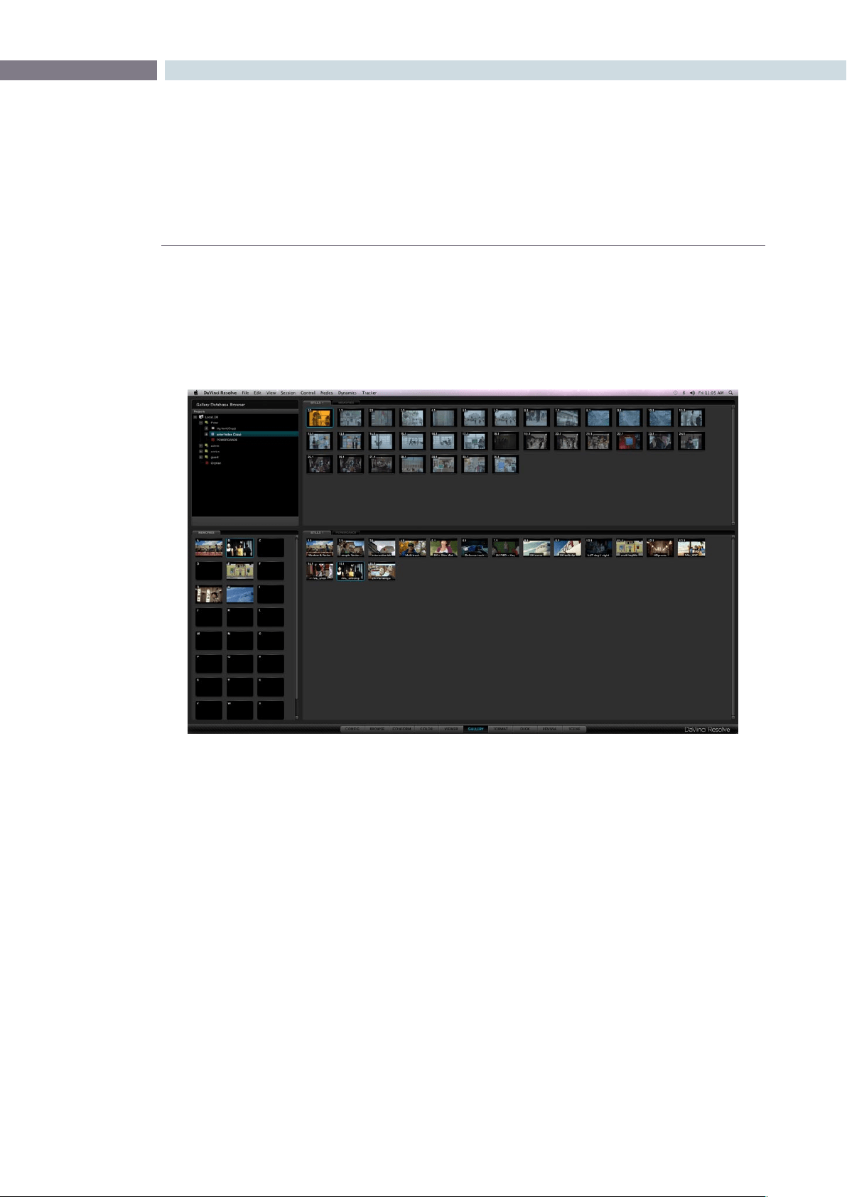
CHAPTER
GALLERY
GALLERY319
11
DaVinci Resolve has a database for projects and also for stills or scene grabs that you can use to
compare with the current scene. This way, reference or important shots can have their grades replicated
in other scenes. You may compare the stored images to those being graded by using a wipe or mix. The
GallerydisplaysthedatabasetosearchforotherprojectsstillsandotherusersstillsaswellastheA-Z
Mems or Memories that offer one key selection on the DaVinci Resolve control surface.
The Gallery screen has four sections. The top half displays the Gallery Database Browser and the tabs
selected for Stills display within that browser. The bottom half of the screen displays the Memories and
Stills that relate to the current project. Stills can be copied between sections by simple click drag and
drop mouse operations.
Gallery
Gallery Screen
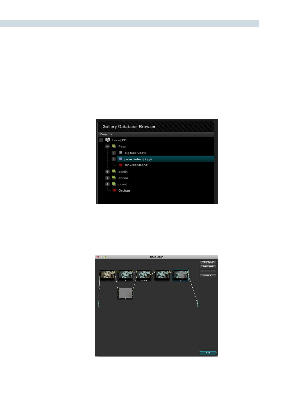
GALLERY 320
Gallery Database Browser
At the top of the Gallery screen is the Database Browser and to the right you will see the tabs as
selected by this browser. Each of the databases connected to this DaVinci Resolve system will be visible
and within each the user names and their projects.
If the user has stored any stills as PowerGrades, these appear in every project for that user, making it
easytoselectandusereferencestillsorgradesfromotherprojects,orjusttokeepthe‘looks’youlike
to use. Remember, each still that is captured also stores the Node Graph, displaying how the grade was
constructedandhelpingyoutocopythewholegradeorjustthePTZRorjustthecolorcorrections,or
individual nodes to the new shot.
Gallery Database Browser
All stills saved include the Node Graph showing the clips grade construction
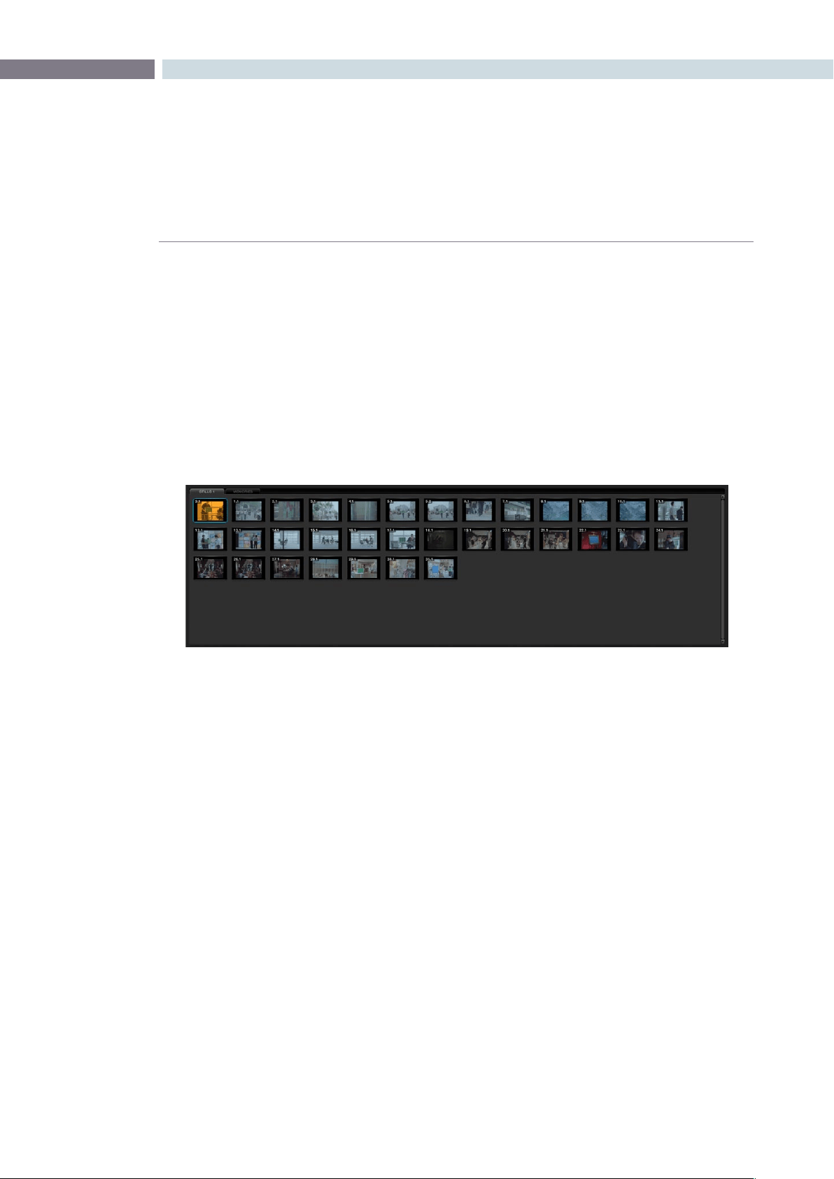
CHAPTER
GALLERY
GALLERY321
11
Gallery Database Tabs
Stills
To the right of the Gallery Database Browser are the Stills tabs which reflect the selection made in the
browser.ThiscanincludestillsfromtheprojectandMemories.Byselectingthe‘GrabStill’buttononthe
control panel, or right-clicking ’Grab Still’ on the viewer, you are capturing a high resolution still image
of the frame currently displayed on the timeline and at the same time capturing the grading metadata
information relating to that grade. This means the still can be used for both visual reference and also for
direct grade copy and paste operations.
The still will be added to the Current Still tab on the Color screen and on the Gallery screen. You can also
delete the stills by using the right-click option. One or a number can be deleted at once. Use the ’Select
current to Last’ or ’First to Current’ options or hold the keyboard shift key while selecting multiple stills.
Stills display a still number in the upper left that is in the scene number/clip number format. The pull-
downoptions‘ChangeLabel’allowsyoutocreateorchangethestilllabel/name.Ifyoursystemhas
Unicodelanguageoptionsloaded,youcanalsoaddnamesindifferentlanguages.The‘current’stillwill
display a cyan border.
Memories
Within DaVinci Resolve, every scene has a grade that is stored in an active Memory. Colorists consistently
refer to this current memory and compare it to the stills to match grades. You can always clear this
memory to get to a default memory, the no grade applied memory, by using the Base Mem control,
which is a right-click selection on the Node Graph or Panel control.
ComparingthecurrentmemoryandmemoriesthatareusedveryofteniseasilydoneusingAtoZ
Memories, which you will find at the bottom of the Still section. These stills are in most respects the same
as the others in the Stills or PowerGrade tab, with the exception that you can save and recall the stills
from the control panel with great speed.
OntheDaVinciResolvecontrolsurface,simplyselect‘Current’andthenoneoftheAtoZMemorykeys
andthecurrentscenegradeissavedtothatMemory.The‘Current’andAtoZkeysareonthefaderand
also the Transport panel. In each case, the Memory is seen in the Memory display with a small letter that
identifies which Memory it was saved in. To recall a grade from the Memory, simply select that Memory
with a one-button selection.
Stills Browser
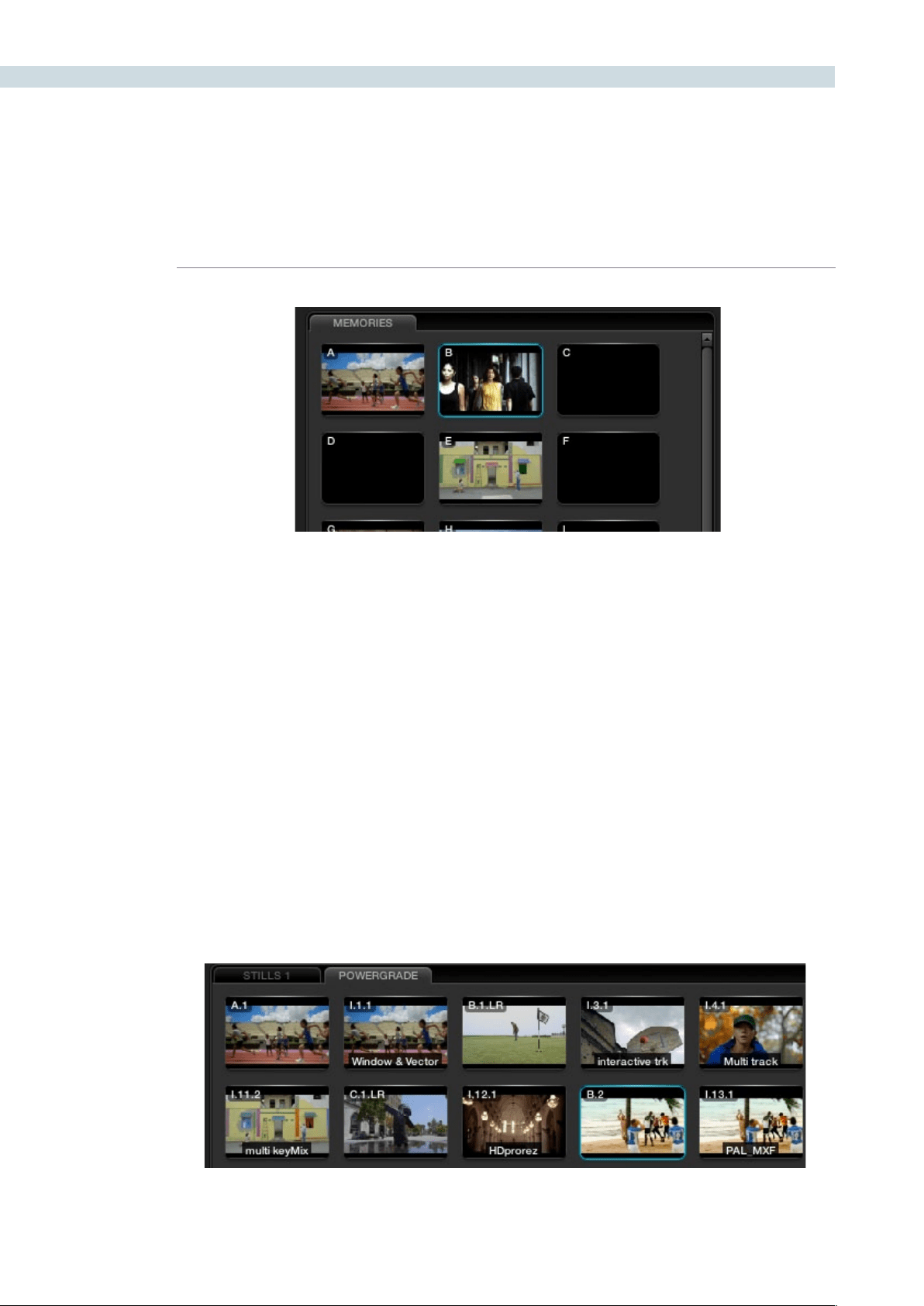
GALLERY 322
A key feature for the stills is the capture and display of the Node Graph which will show the user how the
grades were constructed. This also applies to the Memories. A right mouse click on an image within the
Stillsdisplayletsyouselecttheoption‘DisplayNodeGraph.’Varioussectionsofthecorrectionmaybe
copied to the current correction by dragging the appropriate nodes to the current Node Graph display
orselectingthe‘ApplyCorrection’buttontocopytheentirecorrectionintothecurrentclip.Thestill
nodes may be dragged on top of an existing node and replace that node’s enhancement or a node can
be dragged and inserted independently into the Node Graph line.
PowerGrades
The PowerGrade tab shows stills that are always available to the individual user, no matter which project
they have open. Typically, stills relate to Sessions within a particular Project. You can always copy stills
from other users and other projects, but this is a manual process and there are times when you may
just want to have specific stills, with their Node Graphs, that are always available to you no matter which
Project you have open.
The PowerGrade stills are the same as all others, in most respects, but the ability to see these stills when
the user opens another Project provides a simple way to copy grading information between Projects. As
the Node Graph is saved with the PowerGrade still, complex multilayer grades with LUTs can be saved
andrecalledwithease.Thisalsomakesthemidealforspecic‘looks’thatacoloristmakesforlateruse.
You can drag stills into the PowerGrade tab from your Memories, or save directly to the tab.
Memories Browser
PowerGrade Tab
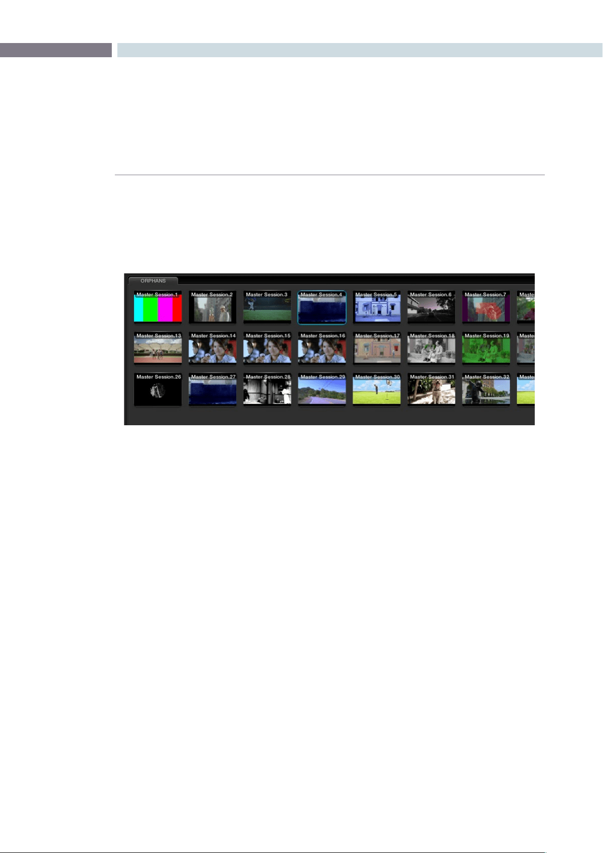
CHAPTER
GALLERY
GALLERY323
11
Orphan Stills
Occasionally, you may delete a Project or the links between the Project and Gallery database become
disconnected. In this case, the stills are not lost, they just become Orphans and are displayed in a tab
for you to delete or move as you like.
Orphans Stills Tab
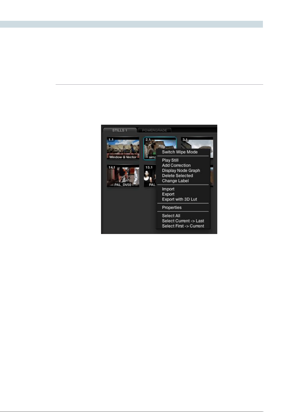
GALLERY 324
The bottom half of the Gallery screen displays the stills related to the current Project. On the left are the
Memories and to the right the Stills and PowerGrades. There are number of right-click options found in
the Stills display. Many mirror the operations from the Color screen, however there are some specifically
for the Gallery.
Switch Wipe Mode
The Switch Wipe mode will select the current timeline clip to compare to either the Gallery still, the
matching offline frame or another clip on the timeline.
In order to match parameters from a Gallery still with that of the actual grading being done, you should
activatetheReferenceWipemodeorselect‘PlayStill.’Youmayselectanothercliptowipeagainstby
selectingthe’Still/Timeline’buttononthepanelsandthenpressingthe‘Previous’or‘Next’buttonson
the DaVinci Resolve Panels to get to the selected clip, or, just use the mouse. When this is done, the clip
being wiped against will be highlighted in yellow. When this function is de-activated, the current clip will
wipe against the image loaded in the Gallery.
IfyouwishtocomparewiththeOfinevideo,toggletheReferenceWipemodeuntilthe‘Ofine’label
isseenonthestatusdisplay.‘ToggleWipeShape’switchesbetweenverticalwipe,horizontalwipe,mix,
orakeyorAlphacontrol.‘ToggleInvertWipe’willswapthereferenceandcurrentimagesintheWipe
display so you can see the other side of the images.
Trace Timeline
Withtheoptionto‘TraceTimeline’selected,thestillthatishighlightedwillalwaysmatchthescene
selected on the main timeline. This mode of operation is not always desired, but can be handy if there
are a very large number of shots and multiple stills for each.
Current Project Stills
Current Project Stills (Right Click)
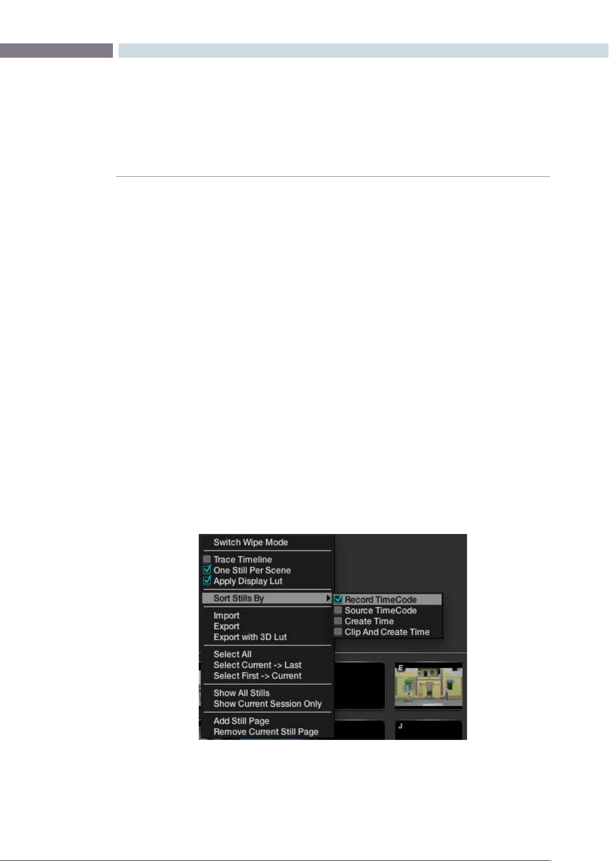
CHAPTER
GALLERY
GALLERY325
11
One Still Per Scene
The‘OneStillPerScene’selectioncaneaseworkowifyouprefertoautomaticallyeraseaprevious
still for a scene when a new one is grabbed. As you grab a still, it replaces the previous still for a scene.
Should you have more than one still for any scene before selecting this option, DaVinci Resolve will
only delete the extra stills when a new grab is made for that scene. This feature, used in conjunction
withthe‘GrabAllStillsfromtheFirst(orMiddle)Frame’isanidealwaytorecapturereferencestillsfor
a completed project.
Apply Display LUT
If you have a Display LUT selected on the Config screen LUT tab, this LUT will be applied to the Grading
monitor output, and also the Viewer display. When you grab a still, you would not want this display
LUTburntintothestillasit’sadisplayLUT,nota‘Look’LUT.ThestillswillappearintheGallerywiththe
correctnon-LUTinuencedimage.The‘ApplyDisplayLUT’featureisusedtoapplythesameLUTtothe
still when it is used for a reference comparison and it is automatically added only during this display, so
the actual still is not affected.
Sorting Stills
To sort stills there are a number of options that are selectable with right click pop-ups. When stills are
added, they are placed next to other stills from the same scene and generally in record timecode order.
You can also select the stills to be sorted and displayed in the order of the source timecode, or the
creation date and time, or by the clip order with the creation date and time.
If you have multiple sessions in your project you can also select to display stills from just this session or
stills from all the sessions.
Current Project Stills (Right Click > Sort Stills Options)
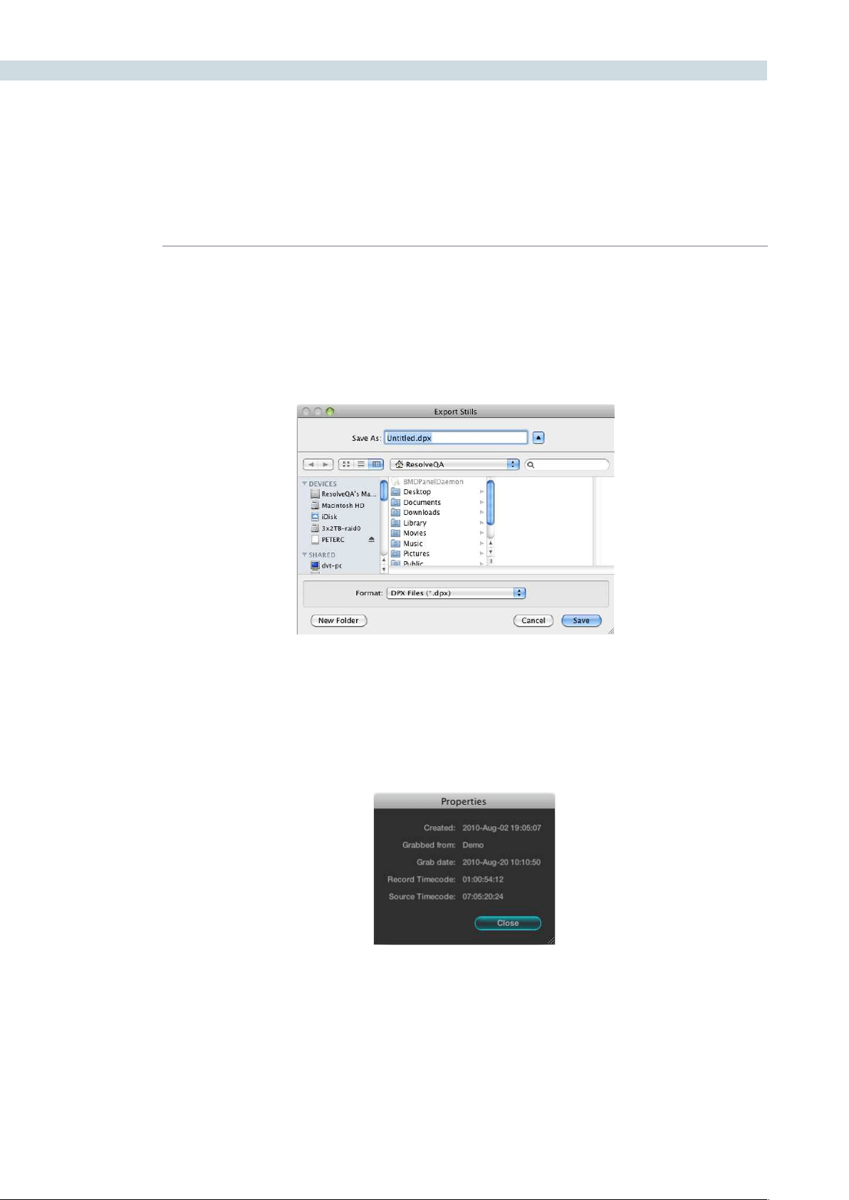
GALLERY 326
Stills Import and Export
You can import and export images in a number of formats simply by selecting the still and right clicking
the Import, Export, or Export with Display LUT option. The Display LUT used in this case is the one
selected on the Configuration screen. The supported file formats for importing and exporting are dpx,
cin, tiff, jpeg, png, ppm, bmp and xpm.
Still Properties
Propertiesofthestillimagecanbesourcedfromtherightclick‘Properties’option.Theseparametersare
used by DaVinci Resolve for sorting the stills.
Adding Gallery Pages
YoucanaddmoreGallerypagestotheGallerystillssectionbyrightmouseclickingandselecting‘Add
Still Page.’ Additionally, if you wish to see a LUT applied to a stored image, this option may also be
selected with a right mouse click.
Stills Properties
Finder Window to Name File and Location
for Exporting Stills


12
Format
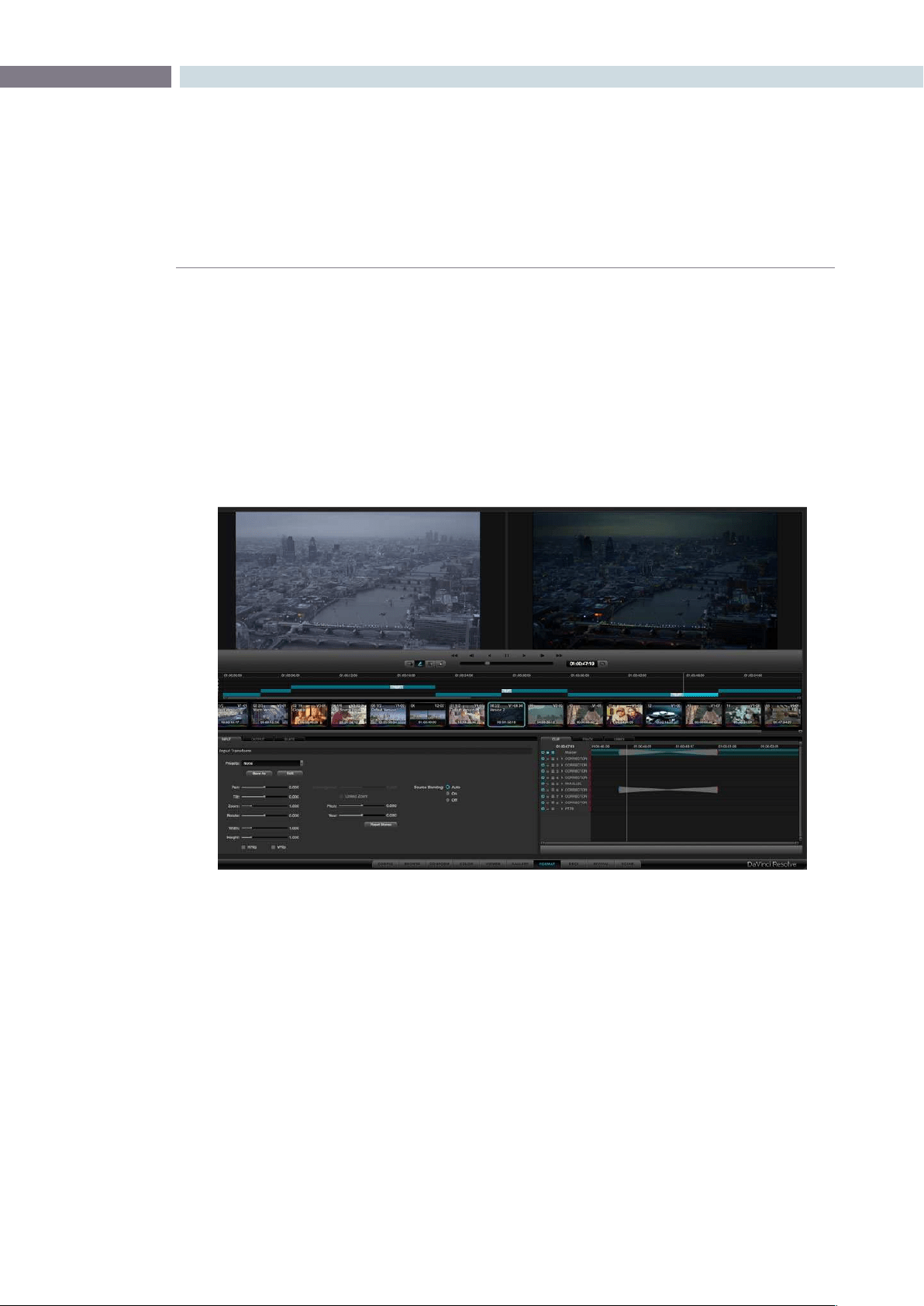
CHAPTER
FORMAT
FORMAT329
12
Format
The Format screen is split into a number of sections. The top half shows the Source image on the left
and the Output image on the right, which will also display the resizing adjustments you make. Under
these viewers you will see the Transport Controls, the timecode of the current frame, and to the left of
the Transport Controls, the same Configuration buttons as found on the Color screen.
These, once again, are as presented on the Color screen. On the lower right is the Dynamic Timeline, and
the Clip, Track, and Unmix tabs for the keyframable dynamics. This allows you to program image reposition
marks and dynamic events and is also a duplicate of the Dynamics Timeline on the Color screen.
Functionally, these all match the Color screen however on the Format screen they all interact with the
controls on the Input, Output, and Slate tabs.
Format Screen
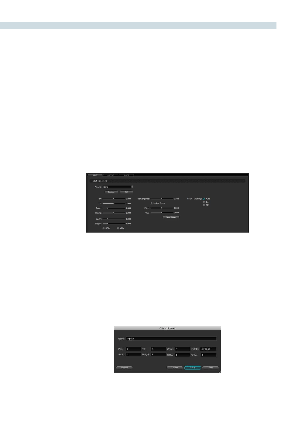
FORMAT 330
All controls on the Input tab refer to the individual clip being adjusted, so the Clip tab is also automatically
selected to show the Dynamics Timeline for the current clip. Select another clip and the settings will
match the dynamics set for that clip. If you have no input adjustments (i.e., no Pan or Size or Rotation,
etc.), the controls will show no variation between clips. However, a simple Pan on the slider control, or
panels, will be displayed on the Input tab and also on the top right image of the Output image.
Input Transform
When you adjust the image format using the Input Transform controls, these changes may also be
programmed within the Clip tab of the Dynamic Timeline as Input Transform settings are all on a clip-
by-clip basis and are keyframable.
Presets
You can create and save custom sizing presets that can be selected and recalled on the Config screen
and also the Browse screen. These presets may be applied as global presets from the Configuration
screen or a Clip preset within the Media Pool. When the Clip tab is selected, the presets may also be
applied from within the Input tab on the Format screen or even by right mouse clicking on a thumbnail
within the Color or Format screens.
TocreateaFormatpreset,simplymakeasizechangewiththeformatterandthenclickonthe‘SaveAs’
button. A window will open showing the values to be saved. Enter a name for your preset, and if you like,
trimanyadjustments.‘Save’toclose,closewithoutsaving,orselect’Default’toresetthevalues.Youwill
then see in the Input Transform Presets list the new preset name.
Youcaneditordeleteanexistingpresetbyselectingthe‘Edit’buttonandeditingthepopup.
Input
Input Format Tab
Input Format Preset Values
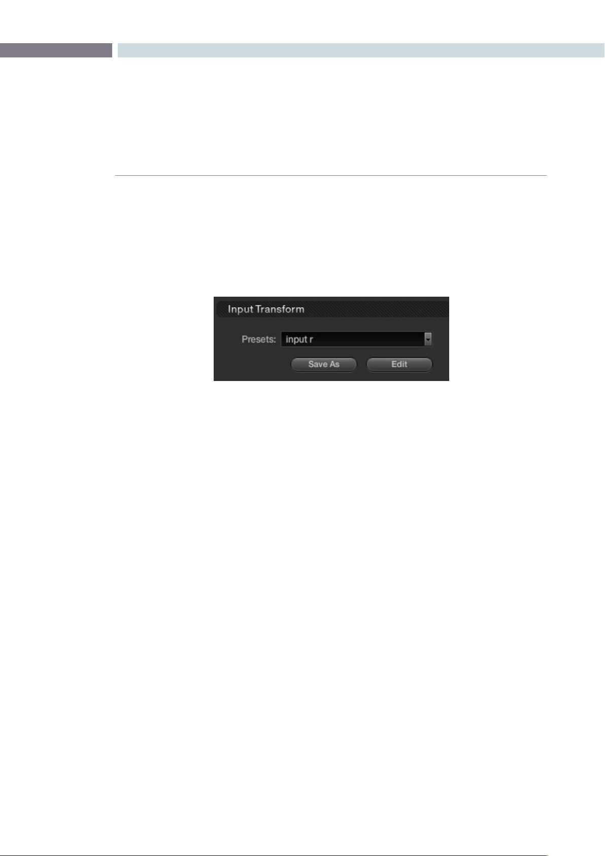
CHAPTER
FORMAT
FORMAT331
12
Input Transform Controls
The first four Input Transform controls mirror the display on the primary tab of the Color screen. Pan, Tilt,
ZoomandRotateadjustmentsmadeonthecontrolpanel,ontheColorscreen,oronthistab,willbe
reflected in the Settings display. Under this group is the input image Width and Height controls. While
typically set at Default, they are sometimes helpful for resizing images that are not correctly scanned.
The next two check boxes are for Horizontal Flip and Vertical Flip of the image.
Source Blanking
The Source Blanking selection will allow you to either switch the source blanking to On, Off, or Auto. This
controlwilladdanti-aliasingtotheimageblanking.Select‘Off’ifyouprefernoanti-aliasingor‘On’ifyou
wish to force it on at all times.
Convergence for Stereoscopic 3D
If you have a stereoscopic 3D session active, the Convergence control will also be enabled to permit the
relative horizontal position of the left and right eye to be adjusted.
ThecheckboxistoenabletheConvergenceWithZoomoption.Thisensuresthatwhenyoupanthe
images to change the convergence, the picture area will always be filled and there will not be black
frames to the left and right edge.
The mirror rigs used for Stereoscopic 3D production may introduce geometric distortion to the image
that can be trimmed using the Pitch and Yaw controls. Rotational adjustments are made around the
horizontal and vertical axis respectively.
The controls are active for 2D projects so that they can be used for creative looks.
Reference Still Resize and Reposition
To reposition images that have been stored within the Gallery on the DaVinci Resolve control surface,
select‘Modes,’‘WipeMode,’andthen‘RefSizing.’TheGalleryimagerepositionfunctionswillberevealed.
You can flip and resize the gallery still, the reference image, and also pan and tilt it to position in the best
location for grading comparison.
Input Preset Selection
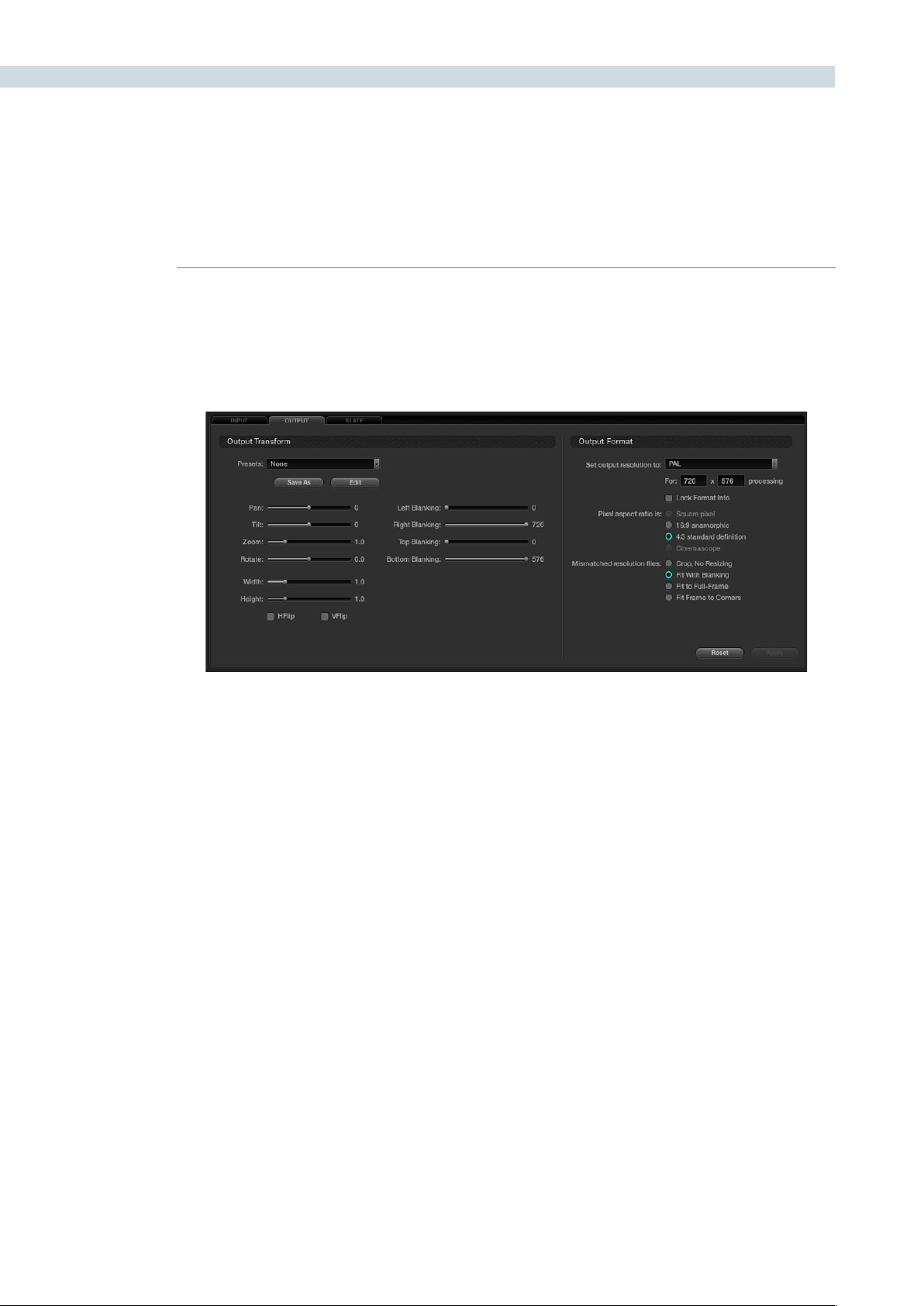
FORMAT 332
If you switch the Dynamics Timeline display to Track mode, this will display the Output tab. By selecting
the Output Tab you will also see the Dynamics Timeline switch to the Track tab as these two are related.
The Output/Track section is designed to create an overall format change for the entire project.
Within the Output tab there are two sections: Output Transform and Output Format.
Output Transform
When you adjust the image format using the Output Transform controls these changes may also be
programmed within the Track tab of the Dynamic Timeline as Output Transform settings are all on a
overall timeline basis and are keyframable.
Presets
Justaswithinputpresets,youcancreateandsavecustomoutputsizingpresetsthatcanbeselected
and recalled on the Config screen and also the Browse screen. These presets may be applied as global
presets from the Configuration screen. When the Track tab is selected, the presets may also be applied
from within the Output tab on the Format screen, or even by right mouse clicking on a thumbnail within
the Color or Format screens.
TocreateaFormatPreset,simplymakeasizechangewiththeformatterandthenclickthe‘SaveAs’
button. A window will open showing the values to be saved. When the Format Preset window pops up
youshouldenteranameforyourpreset,andifyoulike,trimanyadjustments.Choose‘Save’toclose,
closewithoutsavingorselect‘Default’toresetthevalues.YouwillthenseeintheOutputTransform
Presets list the new preset name.
Output
Output Format Tab
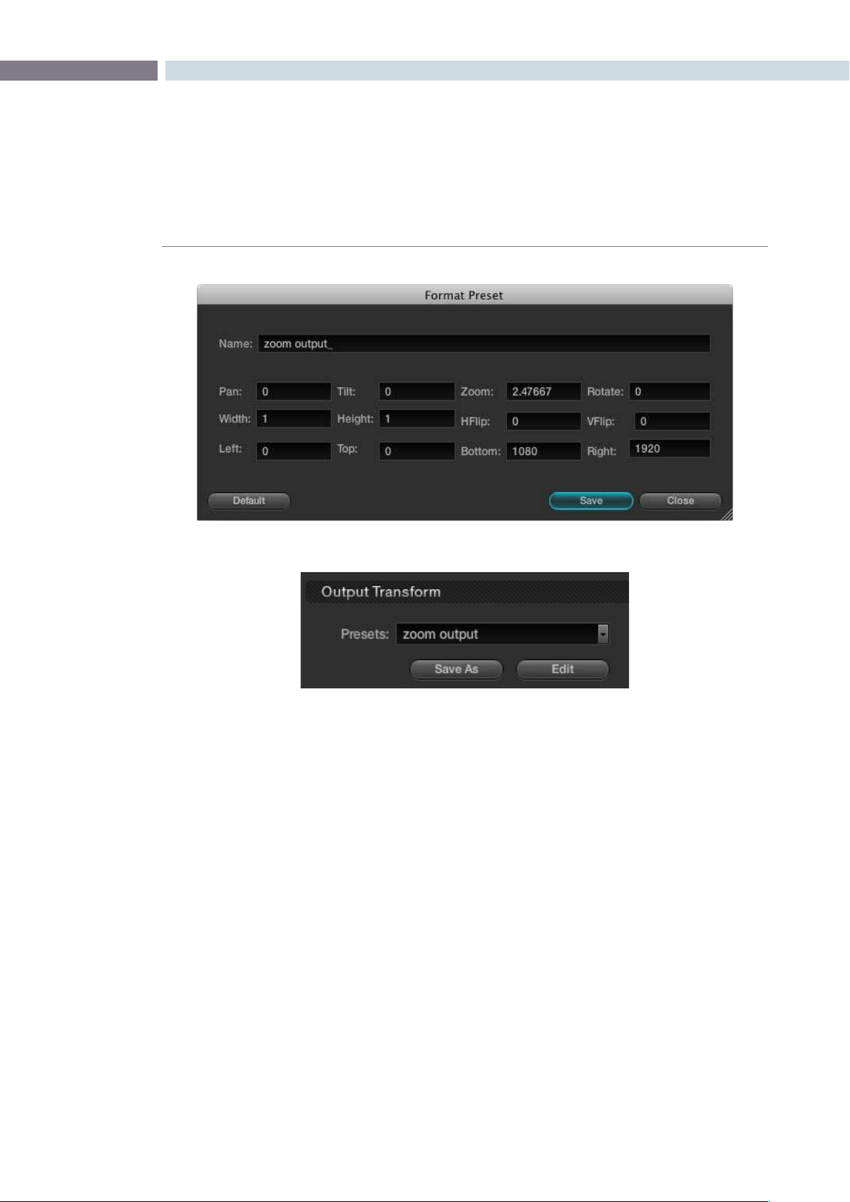
CHAPTER
FORMAT
FORMAT333
12
Transform Controls
LiketheInputTransformcontrols,thersteightOutputTransformcontrolsarePan,Tilt,Zoomand
Rotate adjustments, followed by Width, Height, HFlip and VFlip. These controls are available on the
DaVinci Resolve control surface and on the Output tab on the Format screen. Unlike the Input Controls,
they do not appear on the Color primary tab display.
Output Blanking
The Output Blanking controls are automatically set by the format of the timeline to match the resolution
selected. You can trim the Left, Right, Top and Bottom blanking. These controls can be selected on the
DaVinci Resolve control panel.
There are preset blanking adjustments for various aspect ratios and you can also store custom blanking
settings for the logged-in user. One page will allow you to store the various settings and the next page
will allow the recall of various settings.
Output Format Presets
Output Format Preset Selection

FORMAT 334
Output Format
This section is used to define the timeline formats and most of the controls match the functionality of
those on the Config screen, System tab. While some control the management of the source files, they
all set the configuration for the timeline, which directly influences the output image format.
You can set the timeline or output resolution from a preset list, which will display the resolution selected
for image processing. To change the setting for resolutions not found in the presets, enter the Width
and Height directly into the text box.
The‘LockFormatInfo’isavailableonlyonthistabanditisusedtopreventaccidentalswitchingof
the timeline resolution. With this box checked, no format changes can be made on the Config or
Format screens.
The Pixel Aspect Ratio (PAR) is used to select other than the normal square pixel format. You can apply
a 16:9 anamorphic pixel aspect, a 4:3 for SD, or Cinemascope ratio.
For mismatch source clip resolutions you can have DaVinci Resolve process the images with the
following options:
Center crop with no resizing This option makes no attempt to resize the image to fit
the aspect ratio selected. A simple crop is used from the
center of the source image if it is larger than the
timeline format.
Scale to full frame with crop This option will automatically insert blanking within the
image area to compensate for a difference in the source to
timeline aspect ratio.
Scale entire image to fit This option will resize the image in order to completely
fill the frame. In some cases, a part of the image will be
cut from the left and right sides of the source image or
the top and bottom. You also have the ability to reposition
the image using the Input Format sizing controls within the
Format screen.
Stretch frame to all corners When you select this option, DaVinci Resolve will fit the
frame to the output aspect ratio. In this mode, the frame
edges will be stretched to the corners and no information
will be lost. However, this option can also result in
squeezing or stretching of the image in order to fit the
output format.
Usethe‘Reset’buttontoresetanyvalueswhichwereenteredtothesettingsasyoufoundwhenyou
openedthetab.Toapplytheadjustments,select‘Apply.’
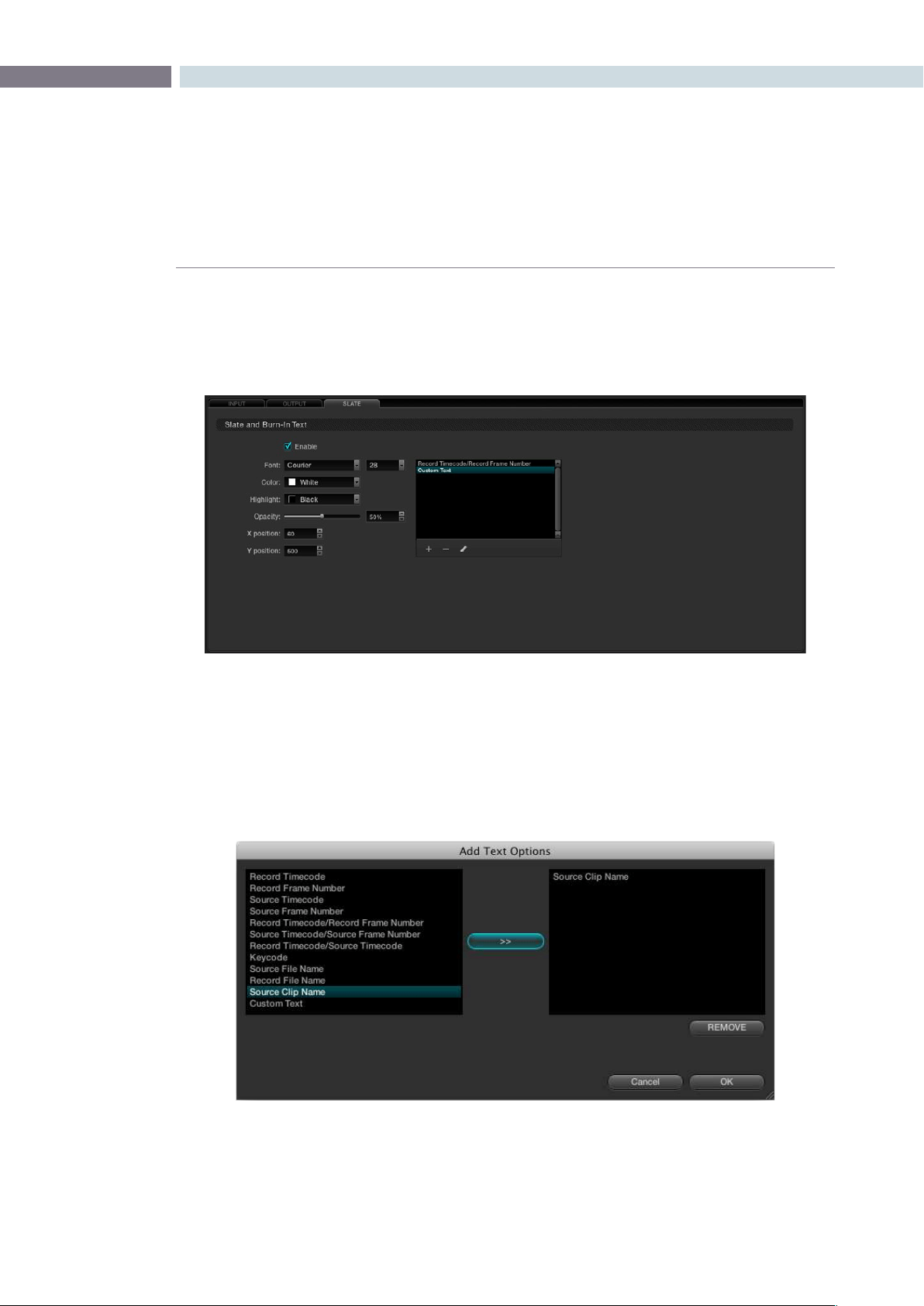
CHAPTER
FORMAT
FORMAT335
12
The third tab of the Format screen is called Slate. It provides control over a simple text character
generator used to burn into the image timecode, frame numbers, and simple custom text. To activate
thisfunction,clickonthe‘Enable’checkboxintheSlateandBurn-InTextsection.Thecontrolsthen
become active.
Underthewindowyouwillseea+,-,andchalkicon.Clickonthe‘+’buttonandawindowwillpopupto
displayoptionsfortext.Selectinganexistingitemandclickingonthe‘–’buttonwilleliminatethattext
from the burn-in.
Within the pop-up window, select items for display on the left and move them to the right list with the
arrowbutton.‘Remove’willdeleteselecteditemsfromthelist.
Slate
Slate Tab
Slate Text Selection
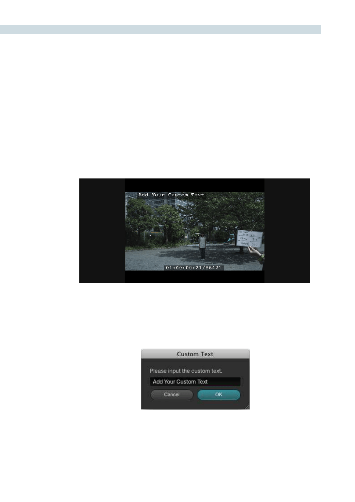
FORMAT 336
Afteryouhavechosenwhichitemswillbeburnt-in,select‘OK,’orselect‘Cancel’toclosethedialogbox
with no change. When you close the pop-up, the items selected will appear in the Slate tab window.
There are a number of controls available that affect the display of the complete list of items. These
include Font, Color, Size, Background Highlight, and Opacity controls to make the text viewable on your
images. Use the X and Y position controls to move each item individually. First select the item in the
window, and type in position values, think of the image size, or use the up and down buttons. Then, go
to the next item and move it.
Custom Text
Ifyouselected‘CustomText’whenaddingitemsfordisplayinthepop-updialogyoucanaddyour
own descriptions to a Project. On the main Slate tab, select the chalk icon under the window listing the
text messages.
Viewer with Slate Text Enabled
Custom Text Dialog


13
Deck
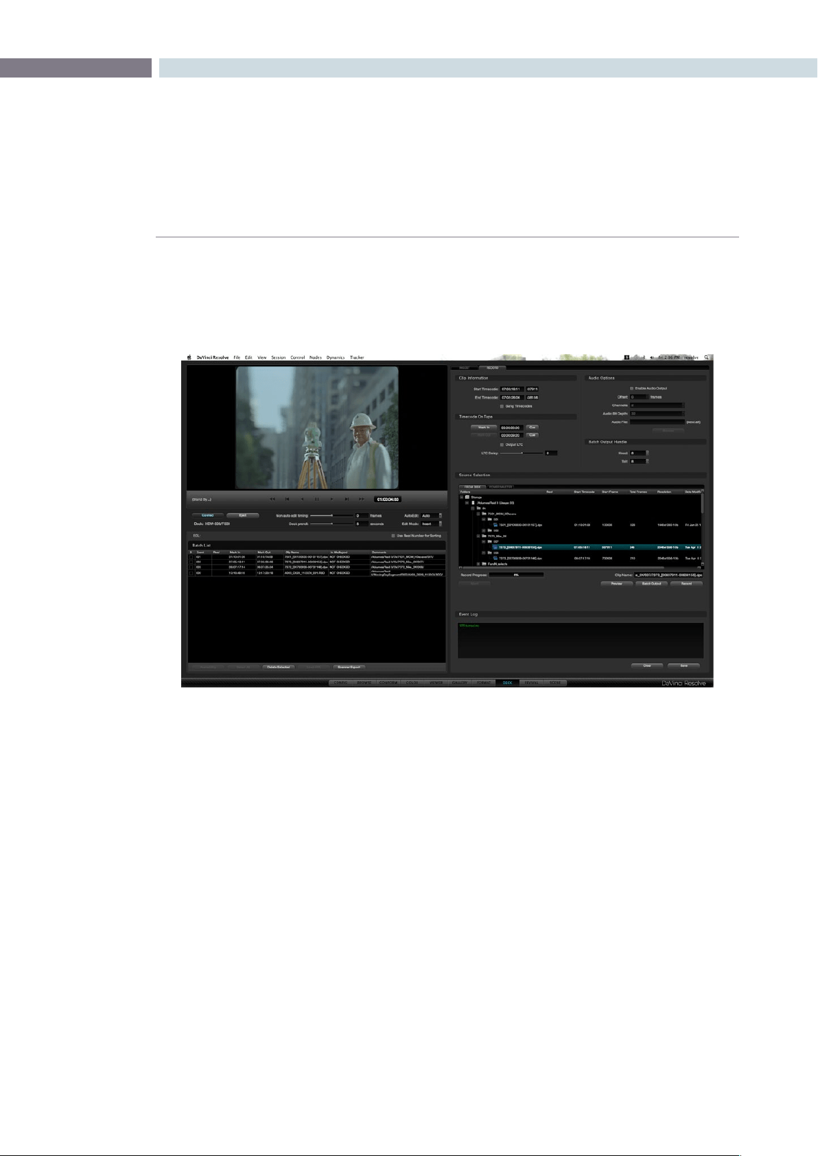
CHAPTER
DECK
DECK339
13
DaVinci Resolve offers video and audio I/O under the control of the Deck screen. There are four main
sections of the screen. The right-hand side has two tabs, one for Ingest control and the other for Record
to tape. The left top section features a Viewer of the DaVinci Resolve or Deck Video output, depending
on mode and transport controls. Below this resides the Batch File Manager.
Stereoscopic 3D material can be ingested or recorded to deck if you have a stereoscopic capable deck.
The stereoscopic 3D modes are enabled in the Deck Capture and Playback section of the configuration
page, project settings tab.
Deck
Deck Screen
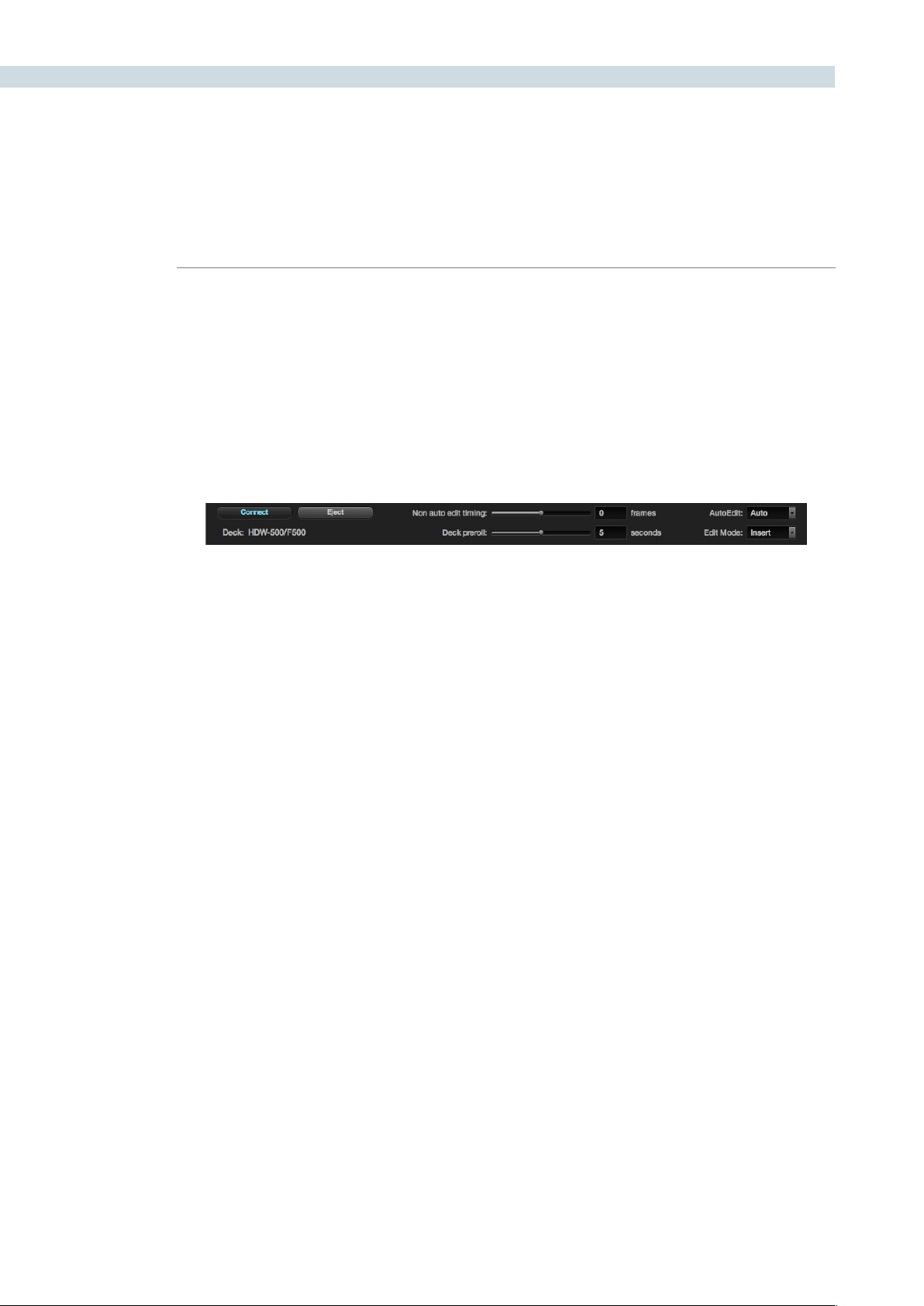
DECK 340
Deck Viewer
The deck viewer displays the video DaVinci Resolve is sending to the deck when in Record mode, or
the video being ingested from the deck when Ingest mode. If you have a deck connected to DaVinci
Resolve, video with embedded audio and RS422 control, then select the Connect button on the left
of the screen just under the viewer and DaVinci Resolve will initiate a connection to the deck. You can
verify that the connection is made when the deck type is displayed, under the Connect button, and by
the status message displayed to the left of the transport controls.
There is an Event Log on the lower right of the screen, which keeps a log of all DaVinci Resolve to deck
communications so you can review this if connection is not established or is dropped. This Event Log
maybesavedusingthe‘Save’buttonundertheLogwindoworclearedbyusingthe‘Clear’button.
Once connected, you can utilize the transport controls to Shuttle, Play, Step or Stop the videotape.
Directlybelowthetransportcontrols,onthepanelwiththe‘Connect’buttonandtheDeckIDlabel,you
will also see a number of other adjustments, all relate to the deck control.
Eject: Will eject the tape that is in the deck.
Non Auto Edit Timing: As also set on the Config screen Project tab, some video
I/O cards perform automatic edit timing and in this case
the slider will be grayed out. For other video cards, adjust
this control to ensure accurate edit timing. Once set for a
particular deck it should not need to be changed.
Deck Preroll: The Preroll selection allows the user to change the deck
preroll (i.e., the position on the tape prior to the edit point
where the deck will start playing). This control mirrors the
setting on the Config screen. The default is five seconds,
which is usually long enough for most decks to lock.
Auto Edit: This selection is the same as on the Config screen System
tab,‘Useautoeditifpossible’allowstheusertoactivate
the non-auto mode for older decks that do not support
auto edit.
Edit Mode: This selection will toggle between Insert, Assemble, and
Crash modes, depending on record operation.
Deck Connection and Edit Controls
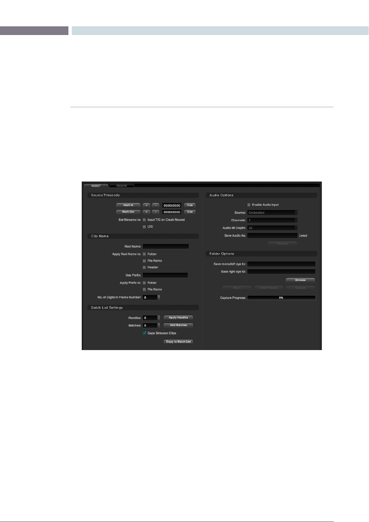
CHAPTER
DECK
DECK341
13
Using the settings on the Ingest tab you can ingest material for color enhancement or as an offline
reference to check the EDL conform of the hi-res material. DaVinci Resolve stores these ingested
images as dpx files. To ingest material into DaVinci Resolve, first verify that the deck I/O settings within
the Configuration screen match the standard for the deck and videotape that has been connected. You
should also verify that the conform rate set on the Config screen is also set to match the incoming video
rate.Next,ontheDeckscreen,selecttheIngesttabandthenclickonthe‘Connect’buttonfoundjust
under the Deck viewer.
If you are using the DeckLink HD Extreme 3 or 3D, you should also make sure the deck you connect to
hastheReferenceSyncoperationsetcorrectly.IfyouareusinganHDdeck,setthedecktothe‘Auto’
syncmode.Inthismodethedeckwilluse‘external’syncreferencewhileinplayout,orifyoudon’thave
an external reference generator like the Mini Converter Sync Generator, it will default to the internal
sync;whenthedeckisinrecordmodeitwillautomaticallyswitchto‘Input’sync.ForanSDdeckwhich
doesnothavean‘Auto’mode,wesuggestyouprovideanexternalsyncsourceandsetthereference
to ’External.’
Ingest
Ingest Tab

DECK 342
Source Timecode
To ingest just a section of the tape, simply go to the selected areas by using the transport controls under
the Viewer, or use the controls on the DaVinci Resolve control surface. Once the correct location has
beenfound,locatethe‘MarkIn’buttonontheDeckScreenIngesttabandclicktoselectthestartpoint,
thenndtheappropriateoutpointonthetapeandselectthe‘MarkOut’buttontoselecttheendpoint.
There are Timecode Trim buttons to step the in and out points forward or back a few frames and you
can quickly cue to these points to verify they are as you like. Or, simply enter the timecode numbers for
the in and out points, if you know them.
You should then define the path in your media storage where the ingested files are to be stored. This
maybetypeddirectlyintothe‘SaveInFolder’area,orifyouwouldlike,usetheBrowsebuttontolocate
a folder on the storage. DaVinci Resolve always makes SMPTE standard .dpx files on ingest.
Atthispointyoumayclickonthe‘Capture’buttontostarttheingest.Ifyouhavemanuallyenteredan
In and Out point, the deck will cue to the In point, plus the defined preroll and begin ingesting material.
Once the Out point has been reached, the process will stop and the clip can be seen within the directory
where it is to be stored.
TherearetwocheckboxoptionsintheSourceTimecodesection.When‘SetlenametoinputT/Con
Crash Record’ is checked, the timecode from the tape when performing a crash record will be used to
updatethelename.Ifyoucheckthe‘SetlenametoLTC’optionwithsomevideoI/Ocards,thiswilluse
an external LTC timecode source connected to DaVinci Resolve as the initiator for the filename.
Clip Name
The clip that you ingest to DaVinci Resolve can have a number of different metadata fields attached
that can assist in workflow and file management during your project. You can apply a Reel Name to
a Folder, File Name, or the dpx header of the recorded file, depending on which options are checked.
There is a field to enter a Reel Name that will also add the text when transferring the ingest settings to
the Batch List.
You may apply a prefix to a File Name or a Folder. Simply checking the boxes next to each prompt and
adding the desired information will activate both items. There is also a setting for the number of digits
in the Frame Number.
Batch List Settings
The Batch List Settings on the lower left of the Deck screen can be used for controlling image ingest
based on an EDL. The events listed within the Batch List can be loaded using an EDL, or loaded from
the information on the Ingest tab, including the timecode and reel name from above. Within the Batch
List Settings display there are also controls for managing the batch list operation.
Toaddhandlestotheingestedmaterialusethe‘ApplyHandles’buttonandsetavalue.Thiswilldirect
DaVinci Resolve to ingest additional material on the beginning and end of the edit points as required.
Thevaluemaybeenteredusingthenumberwindowlocatedtotheleftofthebutton.Selectthe‘Add
Batches’ button to append additional entries to the Batch List display. The amount is selected by the
value to the left of the button.

CHAPTER
DECK
DECK343
13
Ifthereisagapbetweenadjacentclips,thismayberetainedbycheckingthe‘GapBetweenClips’
option.The‘CopytoBatchList’buttonwillincorporatethemanuallyenteredinformationintotheEDL,
allowing the user to modify the EDL information. Further information on the Batch List section can be
found later in this chapter.
Audio Options
While DaVinci Resolve is a color grading and enhancement system, it will record and play audio,
principally to be used as a guide track during grading or for preview of the completed Project. To ingest
audio,rstselectthe‘EnableAudioIngest’checkbox.Then,usingthepull-downmenu,selecttheSource
of the audio and then the number of audio Channels. You should also select the audio file Bit Depth and
then a file name and location to record the .wav file. Use the ’Browse’ button to select a location.
Folder Options
To select the location for storage of the mono or stereoscopic left images to be ingested, use the
Browse button in the Folder Options section, or just type in the path. The individual frames of video
will be labeled with their source timecode or the code you select, with the appropriate metadata as
you selected in the other sections of this tab. If you have a deck capable of playing stereoscopic 3D
imagesinrealtime,andhaveselectedthe‘EnableStereoVideo’checkboxonthecongurationtab,
deckcapturesection,youwillneedtospecifythedestinationtorecordtherighteye.Justclickinthe
‘Selectedrighteyeclip’windowandselectbrowsejustasyoudoforamonoorlefteyeselection.
Capture
Byselecting‘Capture,’DaVinciResolvewillstarttheingestprocedure.Youcanmonitortheprogresson
theviewerandtheCaptureProgressbarandaborttheoperationbyselectingthe‘Abort’button.
Forsimplelimitedsettingsandnoprerollrecording,the‘CrashRecord’buttonwillrecordmaterial
without a preroll. Once the ingest process is complete, the clips will be available in the folder you set
within your media storage. You can quickly check these within the Browse screen.
Disconnect
ToleavetheDeckscreenyoushoulddisconnectthedeckbyonceagainselectingthe‘Connect’button.
You must disconnect from the Deck to leave this screen.
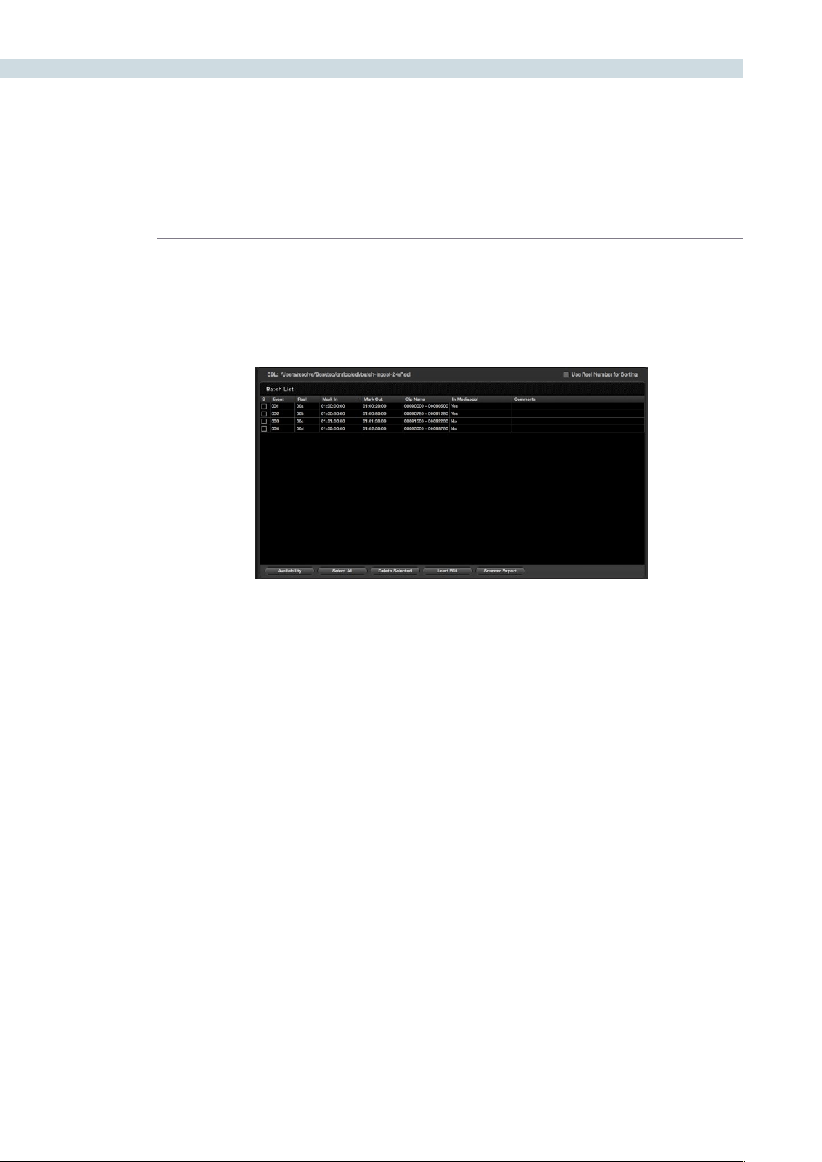
DECK 344
EDL Ingest
WhenyouhaveanEDL,youcanusethe‘LoadEDL’buttonlocatedatthebottomoftheBatchList
display. Selecting this button will open a Browse window so you can select the EDL to load, and once
loaded, you will see the EDL file name listed at the top of the window and all the events in the Batch
List.TotherightoftheEDLnameisacheckbox,‘UseReelNumberforSorting’whichyoushouldcheck
if you would like the EDL to be sorted by reel number, otherwise it will be sorted by source timecode.
TheBatchListdisplayshows,byevent,theReelName,the‘MarkIn’and‘MarkOut’points,andtheClip
Name that will be ingested into DaVinci Resolve. The check box on the left of each item in the display
will indicate when each event has been successfully ingested by displaying a white check in the box. On
the right-hand side of the display, the user will see if the images are available within the Media Pool and
comments,ifany.AtthebottomoftheBatchListdisplayalongwiththe‘LoadEDL’buttontherearea
number of control buttons.
If you load an EDL and some images for that EDL are already in the Media Pool, there is no reason to
ingest them again so this offers a quick check to help reduce your ingest time. Using the active EDL,
DaVinci Resolve will show you the missing clips, making ingest of the remainder quite a lot faster than
the complete list.
Clickingonthe‘SelectAll’buttonwillhighlightalleditswithintheBatchListdisplay.Ifyouclickonthe
‘DeleteSelected’button,thiswilldeletethehighlightededitinformation.Thisgivesyoutheopportunity
to remove events from the batch and ingest only the selected sections from the EDL.
You can also ingest material using multiple EDLs. Particularly helpful for a TV commercial project. First
placealltheEDLswithinthesamedirectoryfolder.Whenyouinitiatethe‘LoadEDL’function,browseto
thedirectorythathastheEDLsandusethe‘Shift’or‘Ctrl/Command’buttonstoselecttheEDLs.
Scan list export
Lastly,atthebottomoftheBatchListdisplayisa‘ScannerExport’button.Thisbuttonwillexport
the events within the Batch List in a format that can be utilized automatically by an Arri scanner. The
scanner can then scan the film and place the frames you need into the Media Pool with the correct
naming convention.
DaVinci Resolve can also optionally populate the Media Pool with the clip entries so you can continue
working as the scan is in progress. The images will appear automatically as soon as the scan has finished.
Batch list for Ingest
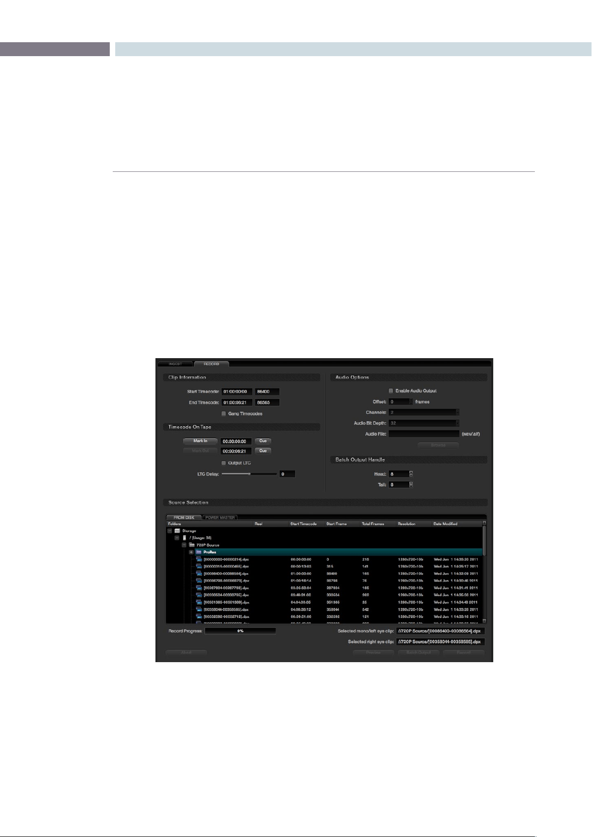
CHAPTER
DECK
DECK345
13
Record
The Record tab provides controls to record images from the media storage disks to a video tape deck.
If you have a PowerMaster project it also offers control over the clips to be recorded from the timeline.
Selecttheappropriateclipfromdiskbrowserinthe‘SourceSelection’tab.Thenacquirethedeckby
clickingonthe‘Connect’buttonandpositionthetapetothelocationwhereyouwanttorecordthe
images,clickingonthe‘MarkIn’buttonwithintheTimecodeonTapesection.Or,simplychoosethe
appropriate section where to record the material on the tape by typing in a timecode.
Check the Assemble/Insert/Crash setting under the Viewer to make sure it’s as you require. Note: When
DaVinci Resolve is performing a Batch Output operation you can only select between recording the
clipswithanAssembleeditoraCrashrecord.Clickonthe‘Record’buttontostarttheprocessof
exporting the material to the tape. Once finished, you can check the recording using the transport
controlsorclickonthe‘Connect’buttononceagaintoreleasecontrolofthemachine.Youwillneedto
disconnect prior to exiting the Deck screen.
Clip Information
Within the Clip Information display you will see the timecode for the start and end of the clip, as defined
bytheclip’smetadata.Trimthestartandendpoints;the+and–buttonswilleitheraddorsubtract
frames from the values displayed.
Deck Page Record Tab

DECK 346
The Gang Timecodes checkbox allows synchronization of the timecode from the tape with the timecode
on the clip. If you want the tape timecode to match the timecode of the clip, select this box and also
make sure your deck is configured to accept incoming VITC (Vertical Interval Timecode) and to record
this to tape with the matching frame.
Timecode on Tape
The Timecode on Tape display shows the In point and Out point where the images will be placed on the
tape.Youmaymanuallymarkthestartpointbypressingthe‘MarkIn’buttonormarktheoutpointby
pressingthe‘MarkOut’button.
Under the timecode display there is a check box for LTC. With a DeckLink HD Extreme 3 or 3D, the
longitudinal timecode is available on track 16 of the HD-SDI video signal so you can use a Mini Converter
de-embedder to extract this analog audio signal and feed it to a recording device. This is particularly
helpful if you have a downstream noise reducer that does not pass the VITC timecode. You can use
the LTC and bypass the noise reducer, compensating the delay using the LTC delay slider, making
sure the image and timecode reach the deck at the same time. With the DVS card there is a separate
timecode output.
Audio Options
WithAudioOptions,whenthe‘EnableAudioOutput’isselected,DaVinciResolvewillplaya.wavor
aif audio file with the images so both can be recorded on tape. Select the appropriate audio file, then
selecttheappropriatesettingsfortheChannels,Offset,andBitDepthsections.Usethe‘Offset(frames)’
control to sync the audio and video.
Batch Output Handles
If you are recording a number of clips to tape rather than a single timeline you can set up a batch list
of events, somewhat similar to the ingest process, and DaVinci Resolve will automatically control the
recording to tape with the correct timecode.
Often these are source clips and so to make later ingest easier, you can add black handles to each of
the clips. The Batch Output Handle display allows you to set Head and Tail Handles to the material being
recorded to tape. It will automatically add black before and after the clip material.
Source Selection
TherearetwotabswithintheSourceSelectiondisplaywhichallowyoutoswitchbetween‘FromDisk’
and‘PowerMaster.’Youcanselectclipsfromwithinthemediastoragetoberecordedtotapewhen
in the From Disk tab. Use the mouse to navigate to the folder with the clip you need and select. It will
then be displayed in the Selected mono/left eye clip window, which you can find just above the Preview,
Batch Output and Record buttons. If you are recording stereoscopic 3D images to tape, just click the
‘Selectedrighteyeclip’windowandselectbrowsetondtherighteyeclipjustasyoudoforamono
or left eye selection.
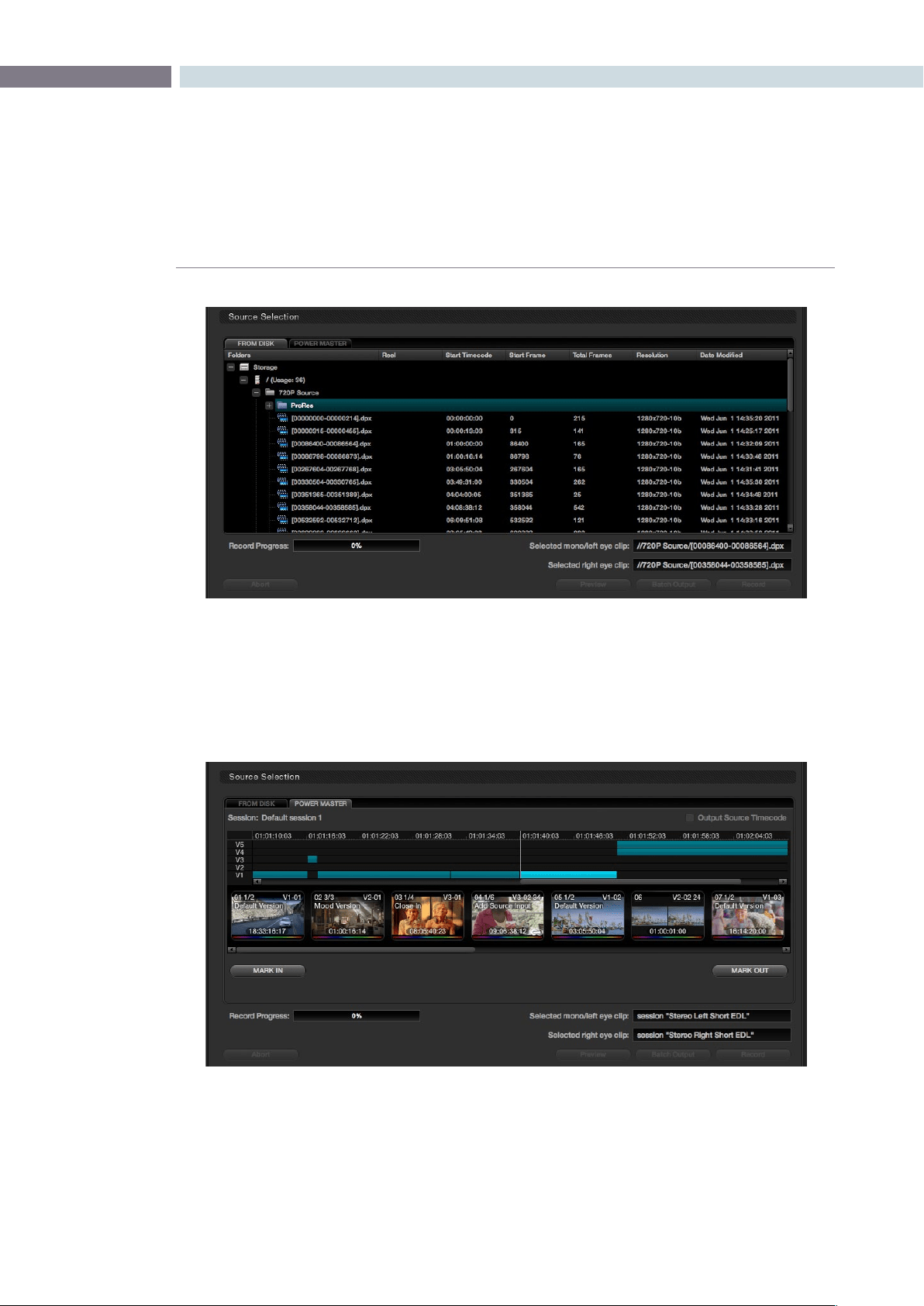
CHAPTER
DECK
DECK347
13
Selecting the PowerMaster tab will open the PowerMaster clip selection display, which allows you to
select a series of clips or a whole timeline that may be recorded to tape while simultaneously applying
the color grading metadata. In this mode you do not have to first render the material to a dpx file
before recording to tape. You save time and disk space with Power Mastering and all the images are at
full quality.
If you are PowerMastering a stereoscopic 3D session to tape, Resolve will automatically populate the left
clip and right clip session details using the current stereo sessions selected in the Conform page. Both
eyes will be played to tape with matching scenes.
Source Selection from Disk
Source Selection from Timeline for PowerMastering
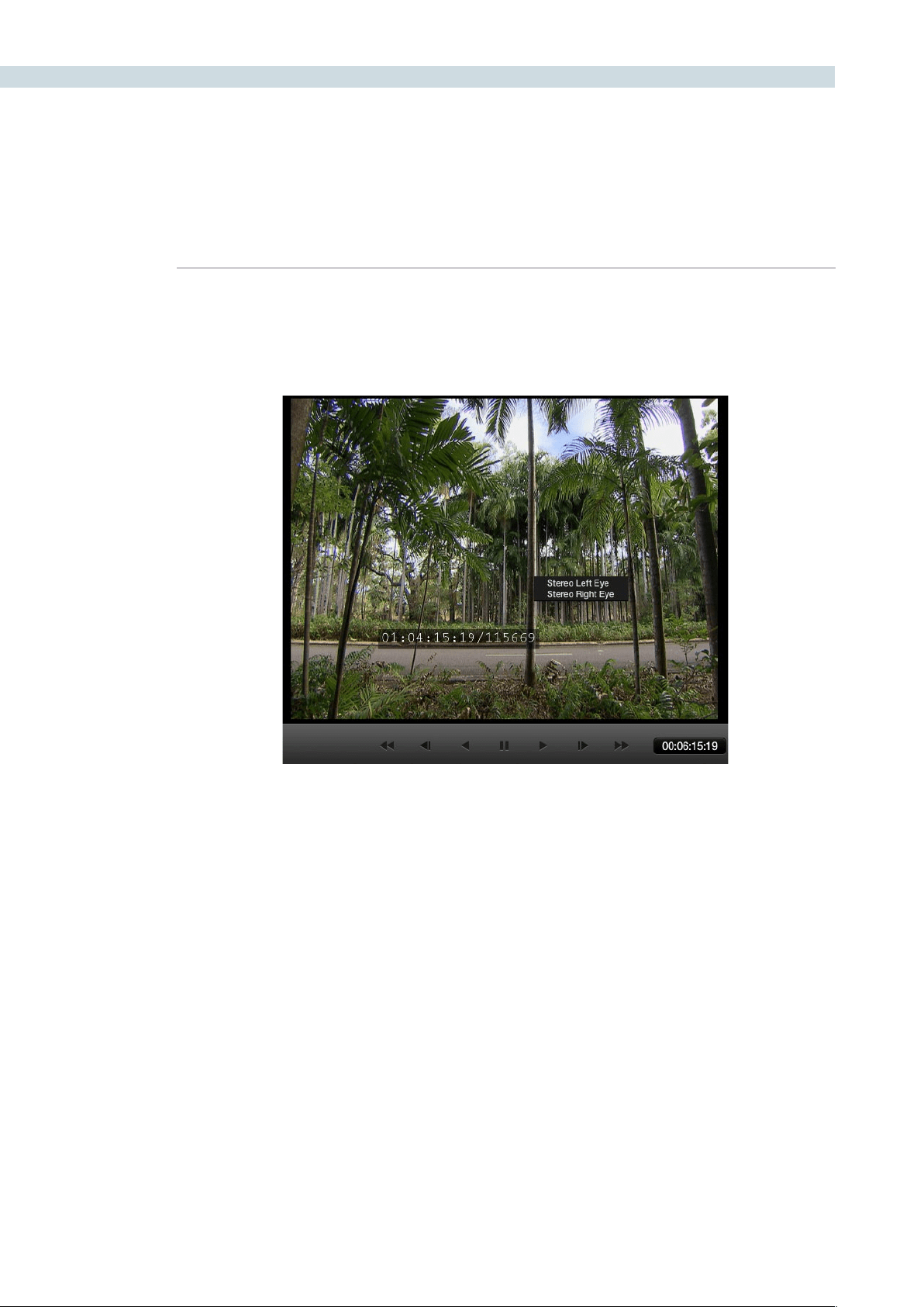
DECK 348
Deck Viewer Stereo Eye Selection
If you are in a stereoscopic deck configuration, simply right click on the deck viewer to select to see
the left or right eye.
Recording
Onceyouhavelocatedtheletorecordandsetuptheothercongurations,selectthe‘Record’button
to start the recording. A Record Progress bar will show the amount of the total clip transferred. If you
wishtostoptherecordingprocess,clickonthe‘Abort’button.
Tochecktherecordingoperationpriortoactuallyrecording,usethe‘Preview’buttonasthiswillpreview
the recording process without actually recording any material.
Batch Output
The‘BatchOutput’buttonisusedtorecordmultiplelestotape.Usethebatchlistontheleft-handside
ofthescreen,alongwiththeamountofhandlesappliedassetbythe‘BatchOutputHandle’controls.
TomakeaBatchRecordingofmultipleclipstotape,selecttheclipsinthe‘FromDisk’browserandright
mouseclickonthem.Fromthepop-uplistselecttheoption‘AddForBatchRecord.’
ABatchRecordofalltheclipsintheBatchListcanbestartedbyclickingthe‘BatchOutput’button.
DaVinci Resolve will make a crash record of the clips to tape with the timecode from the source clip
being recorded to tape.
Deck Viewer Stereo Eye Selection


14
Revival
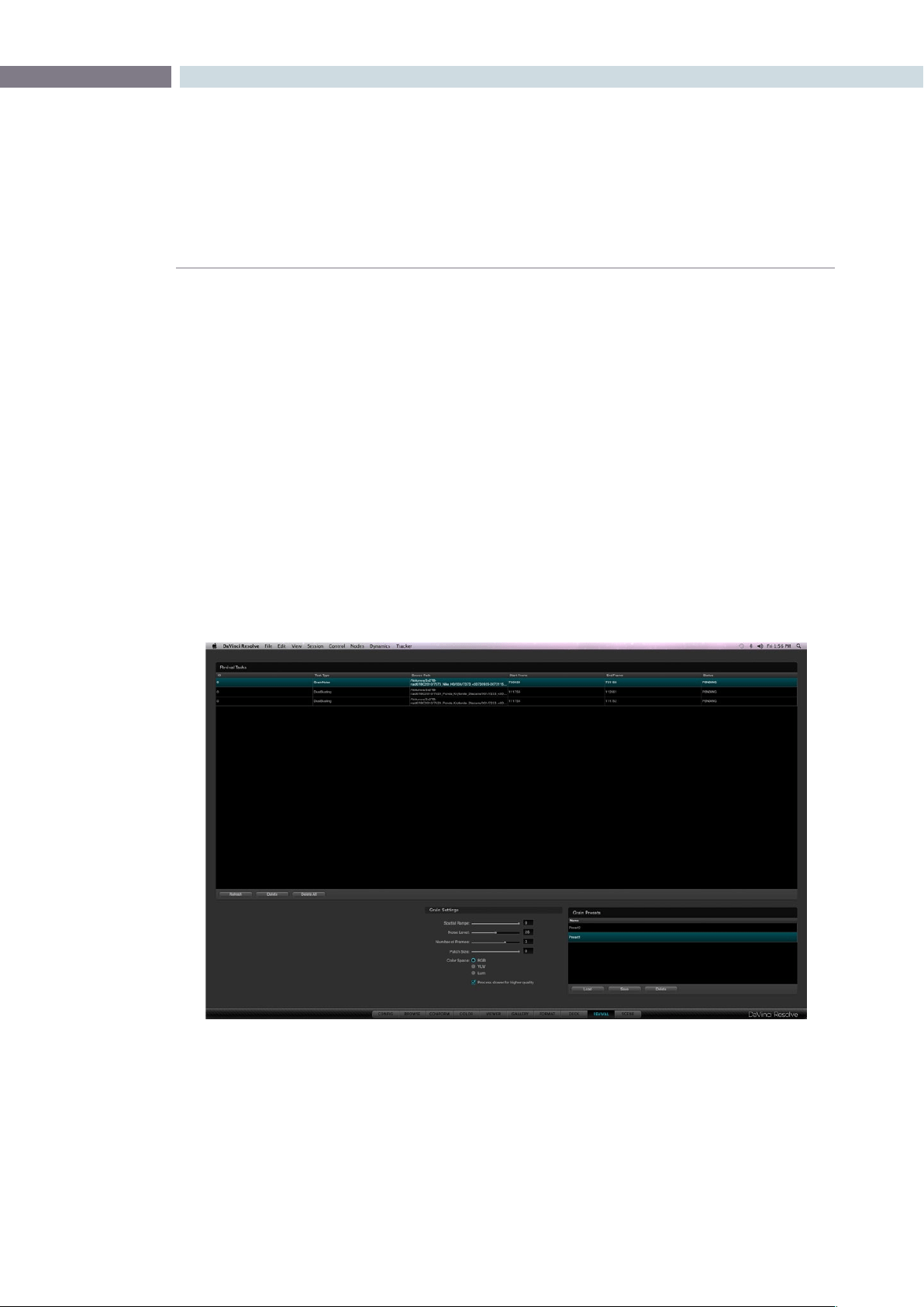
CHAPTER
REVIVAL
REVIVAL351
14
DaVinci Revival
As the leading color correction and image enhancement system, DaVinci Resolve also works with
the DaVinci Revival, the leading system for film restoration. DaVinci Revival has been used to repair
thousands of films over the last ten years, and remains the backbone of many film restoration facilities.
DaVinci Resolve and DaVinci Revival are operated in very different ways because the end product is
quite different. Grading is very creative and flowing, whereas restoration work is often detailed on one
frame for some time. Within DaVinci Resolve, the colorist can perform real time noise reduction or make
simple Dirt and Dust touchups using the repair brush, but more complex repairs, major dust busting
or heavy grain reduction, deWarp, deFlicker, stabilization, deStain, etc., tasks are better performed in
DaVinci Revival; which is a purpose-built restoration system.
Other than the real time noise reduction and manual Dirt correction, DaVinci Resolve does not perform
image restoration, but it does provide details to a DaVinci Revival user for that repair. The Revival screen
provides a list of clips and frames, marked by the colorist, that the Revival operator can review.
There are three buttons in the main display that permit you to Refresh the list, Delete a selected clip from
the processing set or Delete All clips from the processing set. Also, on the lower right-hand side of the
DaVinci Revival display are the Grain Settings controls and presets. This area is used by the colorist to
establish grain settings, which are used by the DaVinci Revival system for grain reduction.
Revival Page
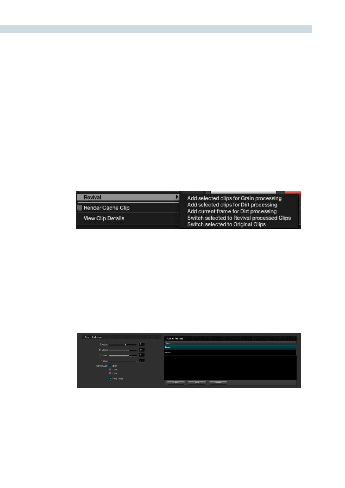
REVIVAL 352
Marking clips for Revival restoration
Clips are marked for restoration using the DaVinci Resolve control panels or via the right click pull-down
list on the Color screen timeline thumbnail for the current clip. The options, as described in the Color
chapter of this guide, are to Add the Current Frame for Dirt Processing, Add the Selected Clips for Dirt
processing, or Add the Selected Clips for Grain Processing. As each selection is made, the request will
join the queue listed on the DaVinci Revival screen.
Selecting DaVinci Revival on the control panels will display the control panel soft keys, giving you the
options for marking the frame or scene just as the mouse selection does on the Color screen thumbnail.
Revival Grain Settings
On the Revival screen within the Grain Settings area, you may set and save recommended settings for
grain reduction. These can be recalled later, adjusted to suit the new image, and saved again.
When you select one of the clips marked for grain reduction, the Grain Settings will become active. They
display the current status of the user controls for grain reduction. You can use these as is, or adjust them.
You can also save the settings as a preset.
Each time you select the same clip, the settings will refresh to show the values for that clip. Use the
’Load’ button to apply other presets to one or many clips.
Resolve Timeline Thumbnail (right click selection for Revival restoration)
Revival Grain Settings

CHAPTER
REVIVAL
REVIVAL353
14
The user controls are:
Spatial (0-20): This control provides a blending of pixels with adjacent
pixels on a single frame. The edges are softened a bit in
order to reduce the fine grain noise. Since this is a spatial
control, processing of one frame does not affect adjacent
frames. A value of zero “0” will turn off spatial processing.
Noise Level (0-50): This control is used in temporal processing of the image.
This value represents a ratio of noise to motion. Higher
levels may tend to cause artifacts on some motion. For
grain, a value of 10-20 is a good starting point. When zero
“0,” there is no temporal or frame-to-frame processing.
Number of Frames (0-20): This value represents the number of frames plus and minus
of the processed frame in which averaging will take place.
This too, is a temporal control and a value of zero “0” turns
off temporal processing. Since it is a plus and minus value,
setting to 3 (typical) will process and average 7 frames (-3,
+3andthecurrentframe).
Patch Size (0-50): This control represents the size of the grain or noise pattern
to be processed. A setting of zero or one would indicate
pixels or grains, and should be used as such.Higher settings
like 40-50 could be used for a lower frequency type of
noise. A typical use for this would be some light form of
flicker in the dark areas. Note: High settings of Noise Level
and Low settings of Patch Size can cause motion artifacts
with some images, so use caution with extreme values for
these controls.
Color Space: This is normally set to RGB to process noise and/or grain in
RGB space. It’s the recommended mode, especially if the
grain or noise has color. This is the highest quality setting,
but takes slightly longer to process. Processing in YUV
mode will process faster than RGB, however a color space
conversion is performed with this mode. The Lum mode is
for luminance-only processing and is recommended only
for black and white material. A color space conversion is
also performed for this process.
Thecheckbox‘Enableforslowerandbetterqualityprocessing’isnormallyselectedtoprovidethebest
image motion preservation and will take longer to process the grain reduction than when deselected.

REVIVAL 354
Here are some recommended starting settings for grain reduction:
Spatial Filter - 0 (Off for no spatial blurring); 2 (Low) for low resolution images; 5 (Medium) for
high-resolution images (will potentially soften the image)
Noise Level - 20
Number of Frames - 3
Patch Size - 0-1
RGB Mode
Safe Enabled
Here are some recommended starting settings for noise reduction:
Spatial Filter - 0 (Off)
Noise Level - 20-30
Number of Frames - 4-8
Patch Size - 20-40
RGB Mode
Safe Enabled
Settings are very subjective and it is highly recommended some testing be done prior to committing a
large amount of work.

15
Scene
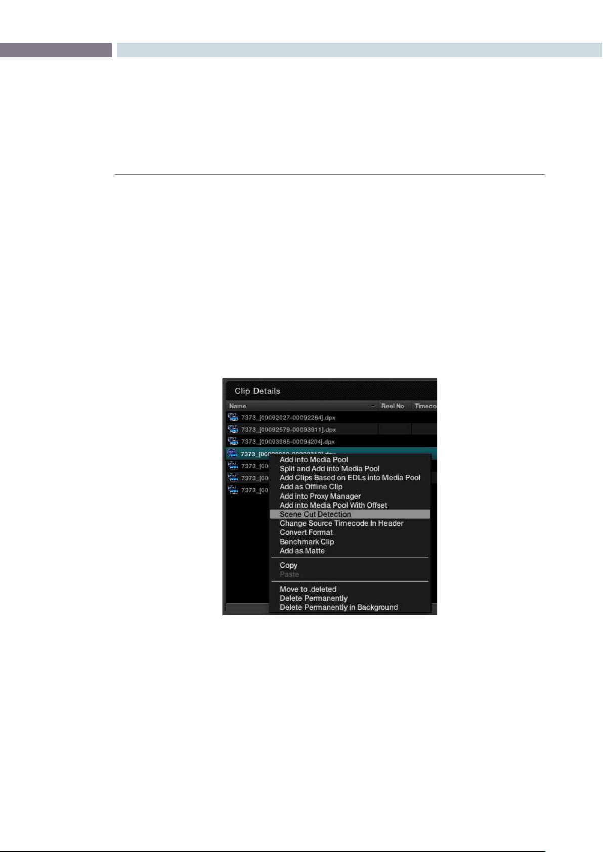
CHAPTER
SCENE
SCENE357
15
Scene
Scene Cut Detector
Often images are supplied in continuous recordings or single streams of files without an EDL to split the
clips. As DaVinci Resolve associates color grading metadata to each clip based on source clip timecode,
any long media files which include a number of clips must have either an EDL or be split into individual
clips so the grade can be applied.
Splitting clips can be done manually on the Color screen or automatically in the Scene Cut Detector.
Loading Clips for Scene Cut Detection
WithintheBrowsescreen,ClipDetails,areahighlightaclip,andrightmouseclicktoselect‘SceneCut
Detection.’ This will automatically load the selected clip into the Scene Cut Detector and switch to this
screen.Select‘StartDetection’tobeginprocessing.
Browse Screen Clip Window (Right Click)
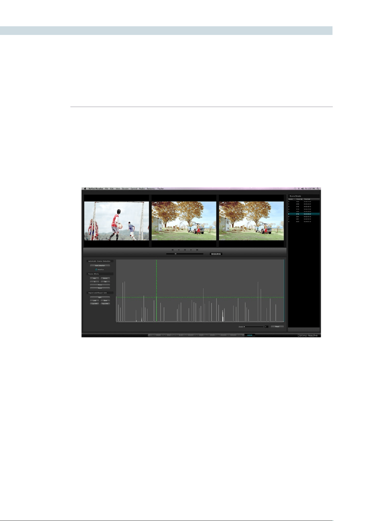
SCENE 358
The top of the screen displays three images. The left image is the last frame of a detected clip. The
center image is the first frame of the next clip and the right image should be the following frame.
Logically, the last frame of a clip will be different from the first frame of the next, and so this timecode
represents the scene cut. The second frame of a clip is very likely, unless they are one frame edits, to be
similar to the first frame.
If the left and center image look similar, the Scene Cut Detector has mistakenly identified this as a cut
point. See the description below for guidance to resolve these false positive points.
Scene Cut Viewers
Scene Window

CHAPTER
SCENE
SCENE359
15
Scene Cut Detector Controls
Below the left image are the controls for the Scene Cut Detector. There are three main groups of controls
for the Scene screen and their operation is as follows.
Automatic Scene Detection
Start Detection: This will start the scene cut detection process.
Auto Cue: When activated, the current frame cursor will jump to the new scene cut, when
detected, and the scene cut will become immediately visible within the Viewer.
Scene Marks
Add: When you click on this button, it will manually add a scene cut at the position
of the current frame indicator within the Scene Cut Detector graph.
Delete: This will delete the scene cut located at the position of the current frame
indicator within the graph.
In: This will insert a red vertical line into the graph for the purposes of eventually
performing a Prune function.
Out: Selecting the Out button will insert a vertical blue line into the graph to indicate
an out point for the purposes of eventually performing a Prune function.
Prune: If you have a number of false positive scene cuts identified, use the in and out
buttons to select a range to prune, the next step is to click on the Prune button
to eliminate any scene cuts between these points that are within one frame of
another scene cut. Within the group of identified cuts, the highest probability
cut will remain while tho other cuts are deleted.
Reset: This will clear any In and Out points.
Export/Import List
Split: Once the scene cut detection process has been completed selecting “Split” will
split the clip into individual clips based upon the scene detection information
and load these clips into the Media Pool.
Save: The scene cut detection information including the probability metadata will
be saved to disk. These files are recognizable as they end with a “.sc” and are
useful to later re-cut a clip.
Load: You can select an existing .sc file and load it into the cut list.
Save EDL: Export the scene detection information in a CMX-style EDL format.
Load EDL: This will load a CMX-style EDL and allow you to use the cut information from
the EDL in the Scene Cut Detection process.
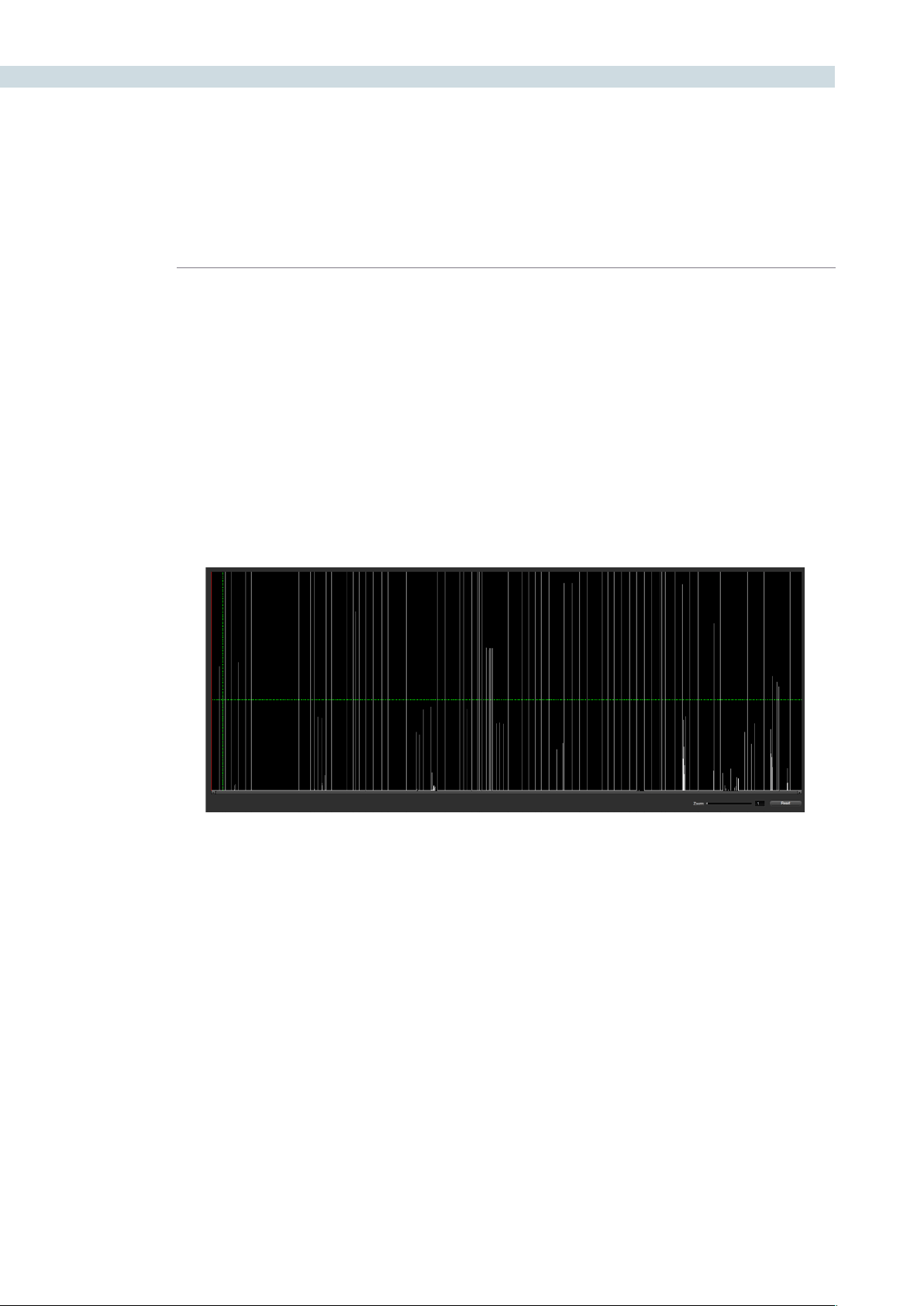
SCENE 360
The bottom half of the screen is dominated by the graph used to display the results of the Scene Cut
Detector’s analysis of the images. As the Scene Cut Detection process is taking place you will see a
visual graph forming. Once the process is completed, the scene changes are listed in the column to the
right of the Scene Cut Detector graph.
The horizontal green bar within the Scene Cut Detector graph represents the sensitivity level for the
detector. If you click and drag it upward, it will lower the sensitivity, and if you lower the bar, it will increase
the sensitivity. When either of these functions are performed, the calculations of where scene cuts occur
will immediately be updated on the cut list.
DaVinci Resolve enables you to adjust the sensitivity of the detection process even after the analysis
has been performed. This is a significant time save in reducing false positive selections and also permits
dynamic review of the cut list.
Scene Cut Detector Graph
Scene Graph
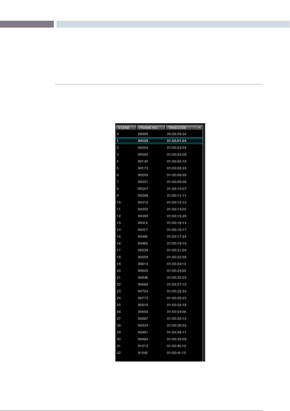
CHAPTER
SCENE
SCENE361
15
Cut List
The right side of the Scene screen displays scene and frame numbers with their timecodes and
represents the cut list as generated from the Scene Cut Detection. This list can be saved, recalled, or just
used to split the clip and load the files into the Media Pool.
Cut List
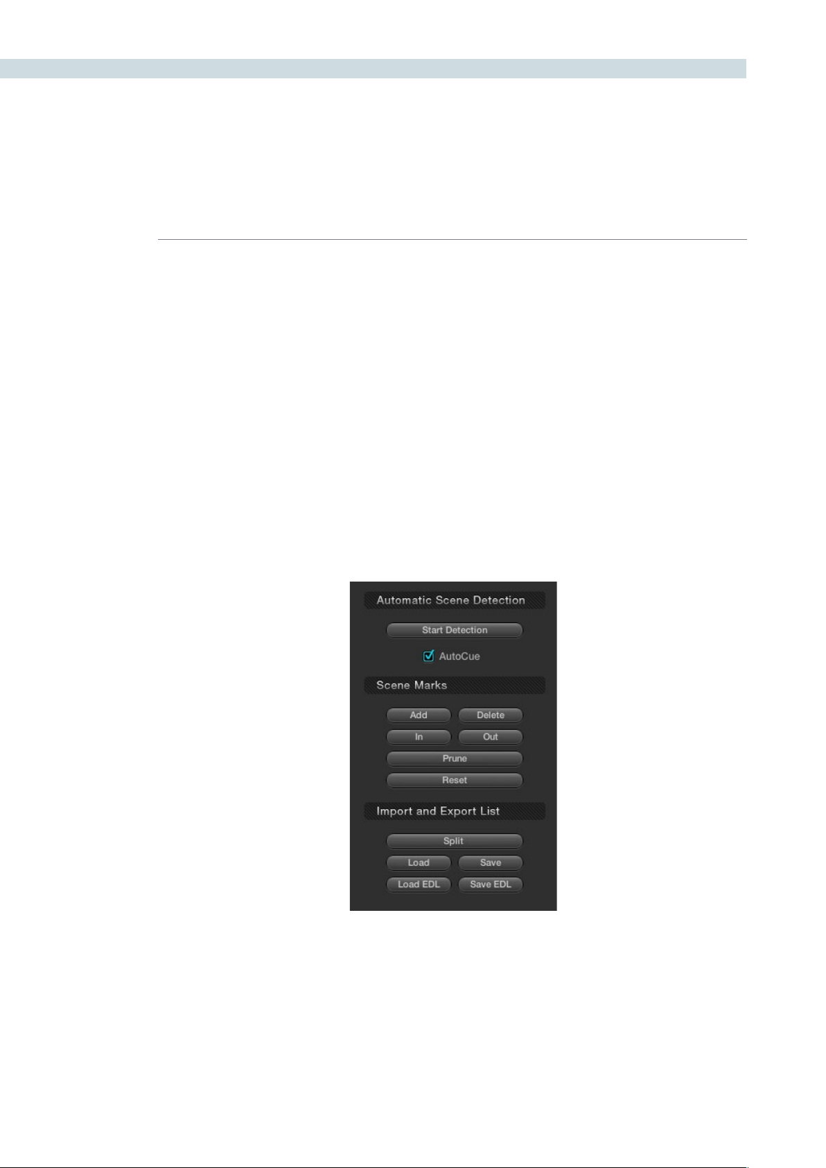
SCENE 362
During or after the Scene Cut Detection process you can begin reviewing the Detector’s analysis of the
image to make sure your cut list matches the actual scene cuts. While the Detector is efficient, it can be
confused by motion, camera flashes, or even the rolling up to and down from full film speed where the
shuttercangivemultiple‘ashes.’Theanalysisislookingforlargechangesintheimage.
The simple method, and fastest way to check to see that the scene cuts are accurate is by pressing
the “N” and “P” keys on the computer keyboard to view the “Next” and “Previous” scene cuts. Look for
the left image to be different from the center and right image. If they are, this is likely to be a scene cut.
As each correct cut point is confirmed, select ’N’ to jump to the next prediction. If the spikes on the
graph are very close together or no cuts are detected, you may need to modify the position of the
horizontal green sensitivity bar and start the cut review again.
If the material which is being scene cut detected, contained certain types of motion which confused
the Scene Cut Detector, you might encounter a group of spikes within the graph that may contain
numerousfalsepositivescenecuts.Todeletethisinformation,use‘Prune’totrimoutscenecutswhich
are grouped between the marked “In” cursor point and the marked “Out” cursor point. Once the marked
InandOutpointsaremarked,andthe‘Prune’buttonisselected,thesescenecutswillbedeleted.
Reviewing the Detected Cuts
Scene Cut Detection Controls
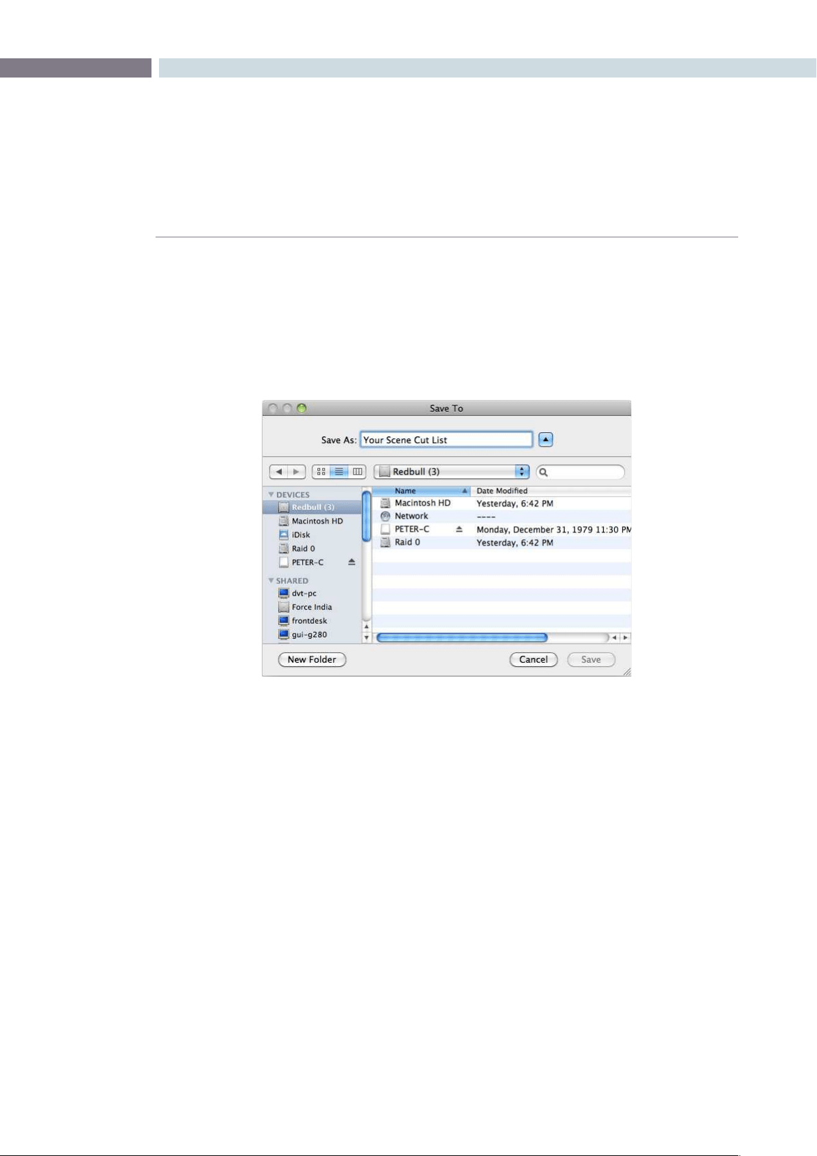
CHAPTER
SCENE
SCENE363
15
Splitting and Saving Cut Lists
Onceyouaresatisedthatthescenecutinformationiscorrect,thenextstepistopressthe‘Split’
button. This will create separate clips based upon the Scene Cut Detection information, the cut list,
and will load these clips into the Media Pool. From there you can begin your Project by creating the
conformed timeline and start grading.
If you have used the Scene Detector to create a cut list for exporting to another device you can save a
CMX-style EDL format list that most professional editing systems can use.
Save the cut list

SCENE 364


16
Render
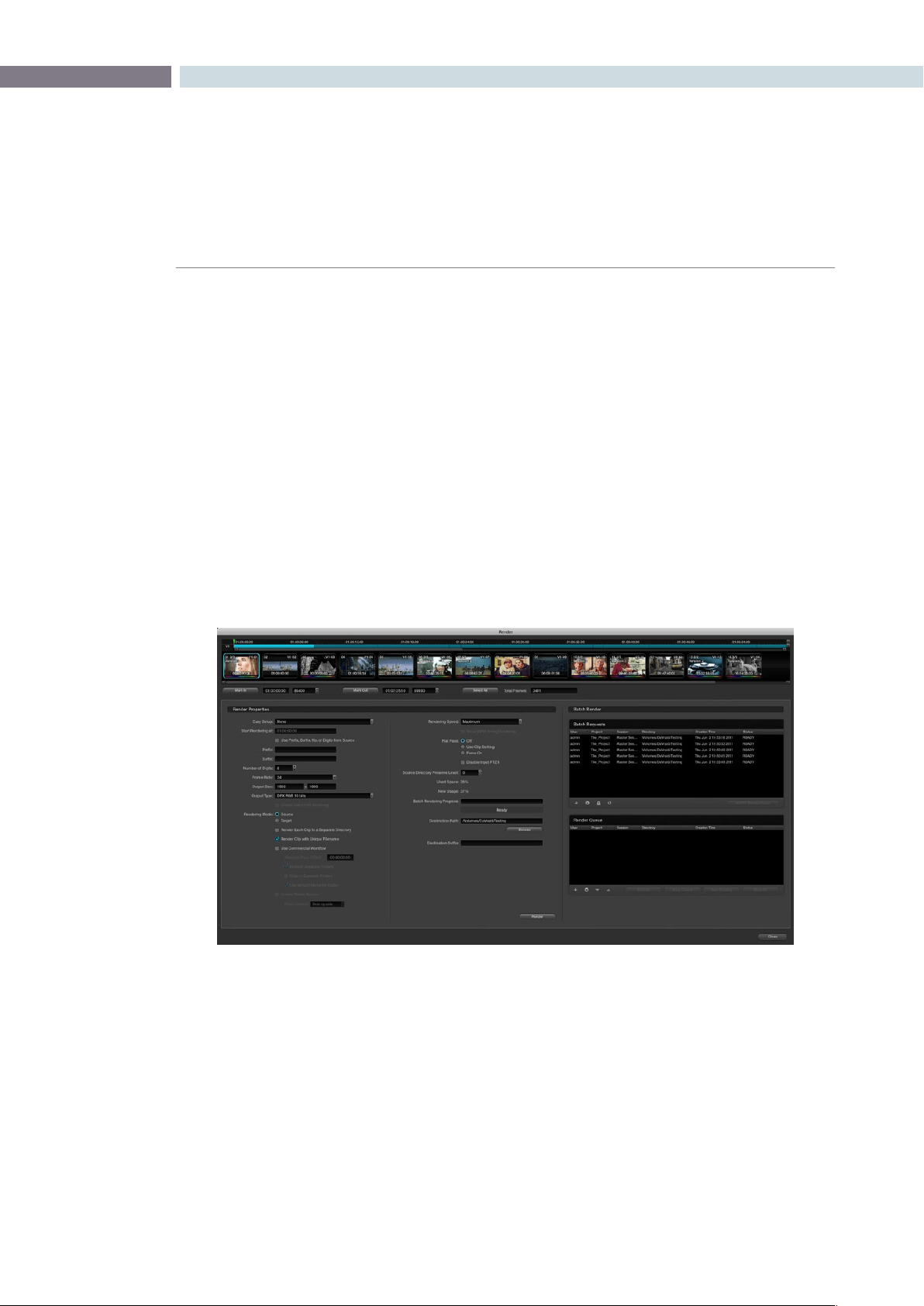
CHAPTER
RENDER
RENDER367
16
The Render screen is used to set up the configuration and initiate rendering of the timeline images.
DaVinci Resolve is not restricted by this limitation and this provides you with significant workflow
advantages.
A simple example of this is using 2K source material and an HD image processing timeline and then
setting DaVinci Resolve to render in ProRes 444, and then render in MXF Avid DNxHD, and then 2K
DPX. All the settings are configurable and permit mastering in all the formats you need without having
to change the timeline processing resolution.
These renders are always performed at the highest resolution possible. If the source clip is 2K and you
have an HD timeline but wish to render in 2K, no problem. DaVinci Resolve will use the source clip and
apply the metadata for that clip as directed by the color correction list with a single resize of the image.
YoucanopentheRenderdisplayfromwithintheColorortheFormatscreensbypressingthe‘Command’
and‘R’keyontheMackeyboard,orusingthemenubarpull-down.OntheDaVinciResolvecontrol
surfaceyoucanalsoselectthe‘Render’button,whichisfoundnearthejogandshuttlecontroloruse
‘ControlR’onthepulloutkeyboard.
Render
The Render Window
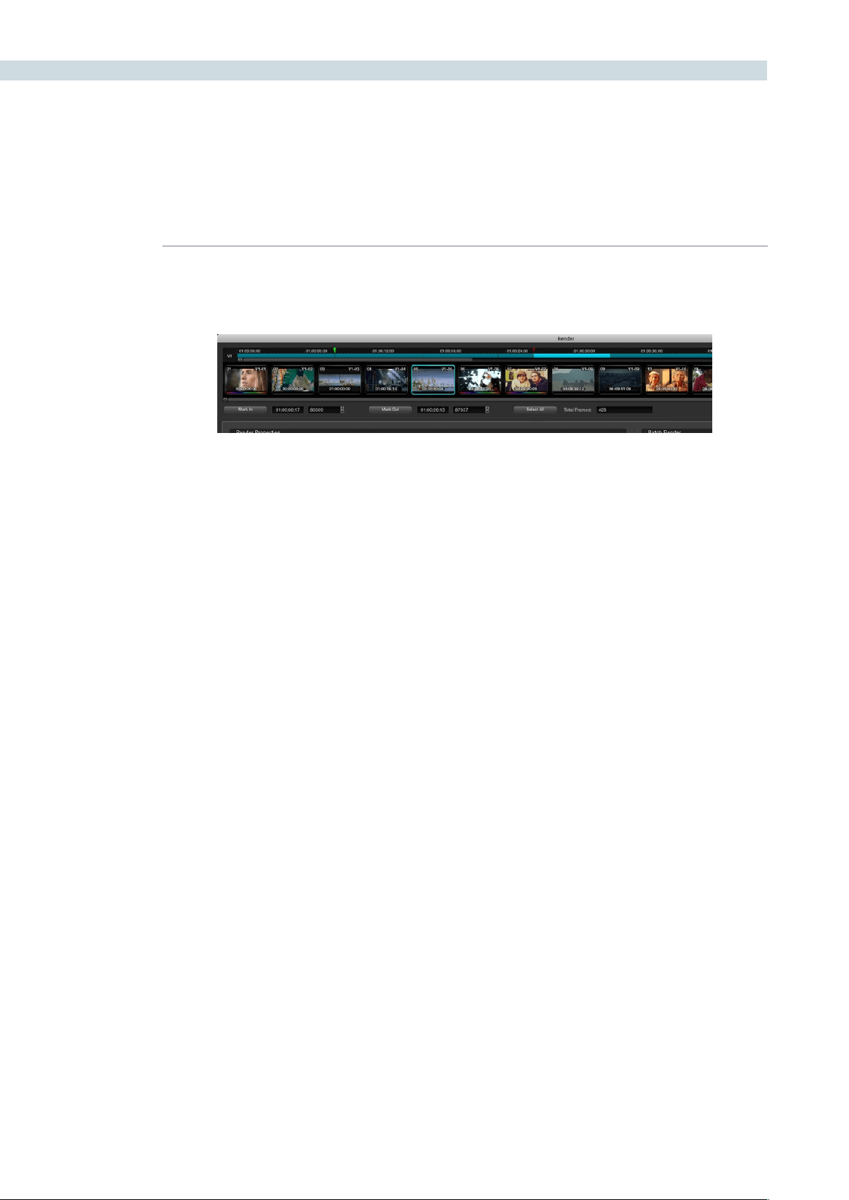
RENDER 368
Render Timeline
The Render Timeline displays every clip in the current session, identically as they appear on the Color
and Format pages.
To render a project, you need to select the range of the Timeline to render.
To select the entire project:
Click the Select All button at the bottom of the Render Timeline.
To select a range of clips to render:
1. Right-click the first clip in the range you want to render and choose Mark In from the
contextual menu, or select the first clip, and click the Mark In button.
2. Right-click the last clip in the range you want to render and choose Mark out from the
contextual menu, or select the last clip, and click the Mark Out button.
As in the previous procedure, In and Out points appear within the timeline ruler to show
the range you’ve selected to render. The in and out fields update with the first and last
frame numbers, in timecode and frame count, and the Total Frames field updates with
the total number of frames you’ll be rendering.
To select a single clip to render:
Right-click any clip in the Render Timeline, and choose Render This Clip from the
contextual menu.
To select an arbitrary range of clips to render:
1. Drag the playhead in the timeline ruler at the top of the Render Timeline to the first of the
range of frames you want to render, and set an In point by doing one of the following:
•Right-clickthetimelinerulerandchooseMarkIn.
•ClicktheMarkInbuttonatthebottomoftheRenderTimeline.
2. Drag the playhead to the last of the range of frames you want to render, and set an Out
point by doing one of the following:
•Right-clickthetimelinerulerandchooseMarkOut.
•ClicktheMarkOutbuttonatthebottomoftheRenderTimeline.
Render Timeline with Mark In and Out Controls

CHAPTER
RENDER
RENDER369
16
In all cases, In and Out points appear within the timeline ruler to show the range of your program that
you’ve selected to render. The in and out fields update with the first and last frame numbers, in timecode
and frame count, and the Total Frames field updates with the total number of frames you’ll be rendering.
Rendering Versions
By default, the currently selected version of each grade is what will be rendered for each clip. If you want
to render a different version of a grade, the easiest thing to do is to make sure they’re selected on the
Color page timeline before you open the Render window.
However, a Versions submenu, within the Render Timeline contextual menu, provides abbreviated
options to manage grade versions, as well as access to the Stereo submenu for managing stereo
grades, the Edit PAR (Pixel Aspect Ratio) command, and a command for updating the Render Window
timeline (colloquially known as the VSR) to reflect any changes you’ve made. Most of these commands
are duplicates of options that are available from the Thumbnail Timeline of the Color page.
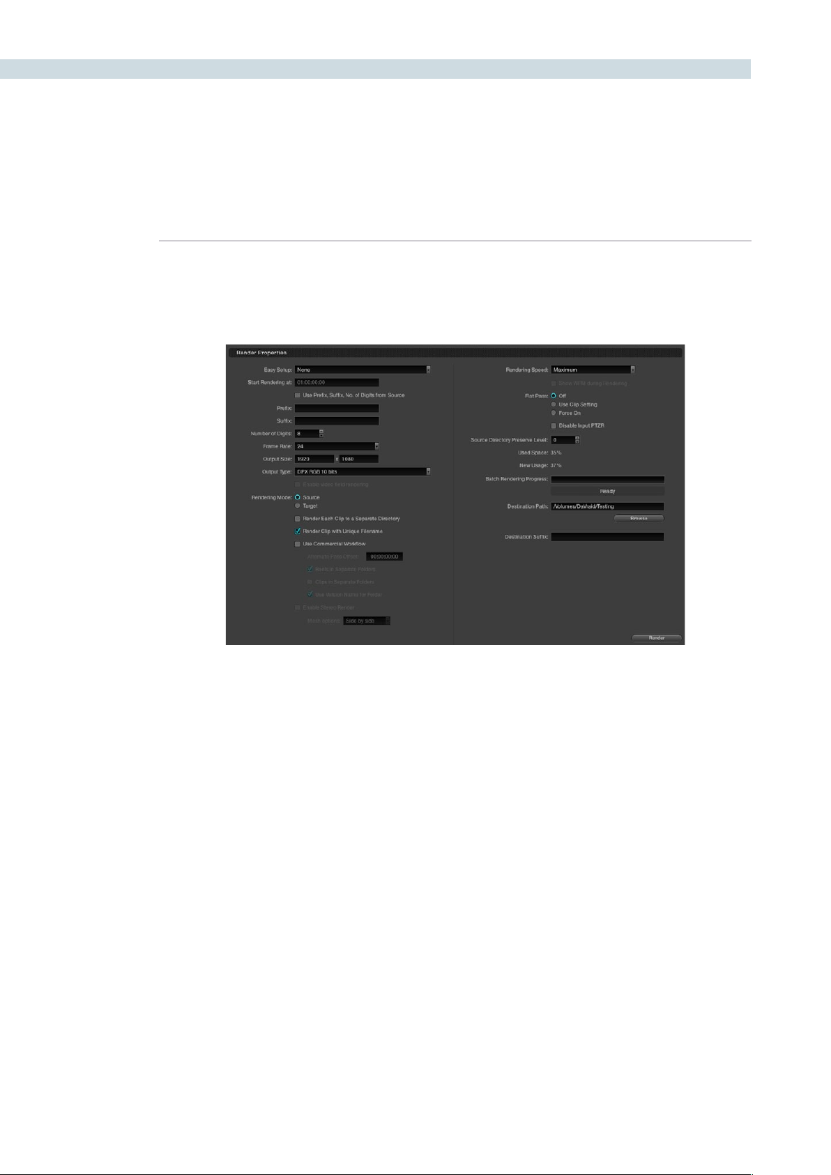
RENDER 370
Render Properties
All the settings in the Render Properties section of the Render screen are important when configuring
DaVinci Resolve to render files. They provide great flexibility and workflow efficiencies, so they will be
described in detail below.
Easy Setup Menu
The Easy Setup pop-up menu lets you quickly choose all the settings that are appropriate to rendering
media for your workflow by selecting a single option. There are three settings:
None: No settings are automatically selected; you must manually choose the settings you need. All
Render Property settings remain as they were the last time you used the Render window.
FCP7 XML Round-Trip: Selects the appropriate settings for projects that were sent from Final Cut Pro
7 to Resolve using XML. This is meant for situations when you’re rendering media intended for a return
trip back to Final Cut Pro (by exporting an XML file from the Conform page). Rendering Mode is set to
source, Output Type defaults to Apple ProRes 422 (HQ), Output Size defaults to the current Timeline
Resolution (as set in the Config page), Render Clip with Unique Filename is turned on, and batch
rendering is disabled.
Export to FCP7: Selects the appropriate settings for projects where media is being initially ingested into
DaVinci Resolve, graded, and output for offline editing in Final Cut Pro. The Render Properties settings
are similar to FCP7 XML Round-Trip, except that Render Clip with Unique Filename is turned off, so that
the File Name, Reel Name, and timecode of the rendered media are identical to the originally ingested
clips in Resolve. This makes it easy to reconform the finished Final Cut Pro offline edit to the original
clips in your Resolve project,
using either XML or EDL workflows (to reconform to the original media via XML, you’ll need to turn
“Automatically import source clips into media pool” off.
Render Properties
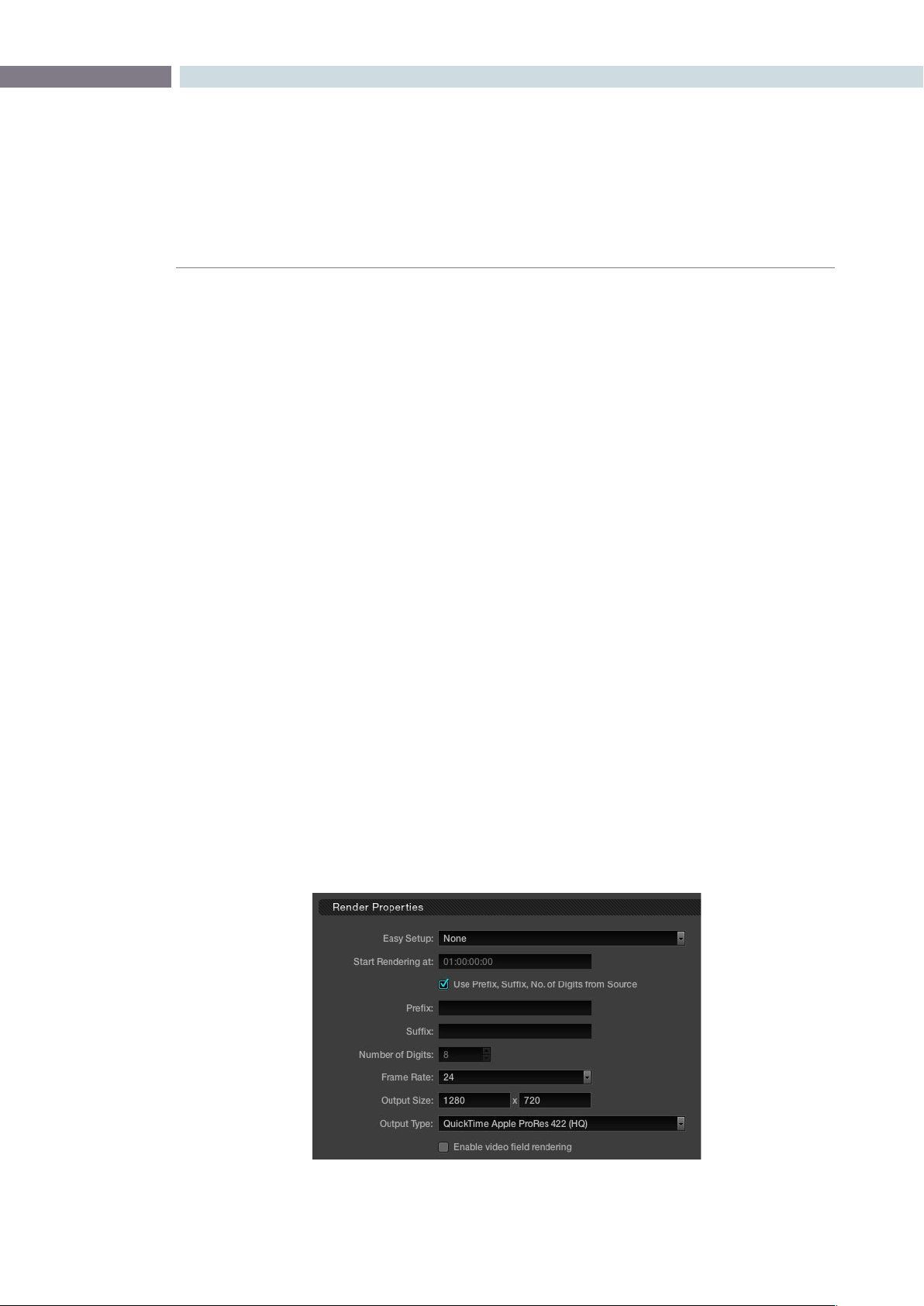
CHAPTER
RENDER
RENDER371
16
Important: When using either FCP7 Easy Setup, make sure you select the appropriate QuickTime codec
from the Output Type pop-up menu before you begin rendering, in case you don’t like the default
codec.
Render Properties Settings
‘Startrenderingat’indicatesthetimecodethatwillberenderedintothedpxleheaderandthisnumber
is also used to label the file, as a frame count. When rendering a timeline there is a logical count of
the frame numbers, permitting simple clip playback on other devices. While typically set to hour one,
you may find it useful to start each reel for a feature film with an increment of the hours. Reel two, for
instance, would start at 02:00:00:00.
Typically, image files are rendered using no Prefix or Suffix and a standard eight-digit length of the File
Name. You can type your own prefix and suffix labels to be used in the file path when rendering or by
checkbox selection use the Source Prefix, Suffix, and number of Digits.
When entering text to use for the Prefix or Suffix, you can also use a selection of variables to
populate these parts of the file name based on clip metadata (you can also use these variables in the
Destination Path field).
%L Filename
%R Resolution
%T EDL Reel
%V Version Name
%I Shot number (within the Rendering Timeline)
%S For stereoscopic projects, the stereo render word (“left” or “right”)
The Number of Digits selection allows the user to enter the amount of digits required for the
rendered file. This is particularly useful to make the rendered files immediately readable by another
manufacturer’s system.
Render Properties (Detail)
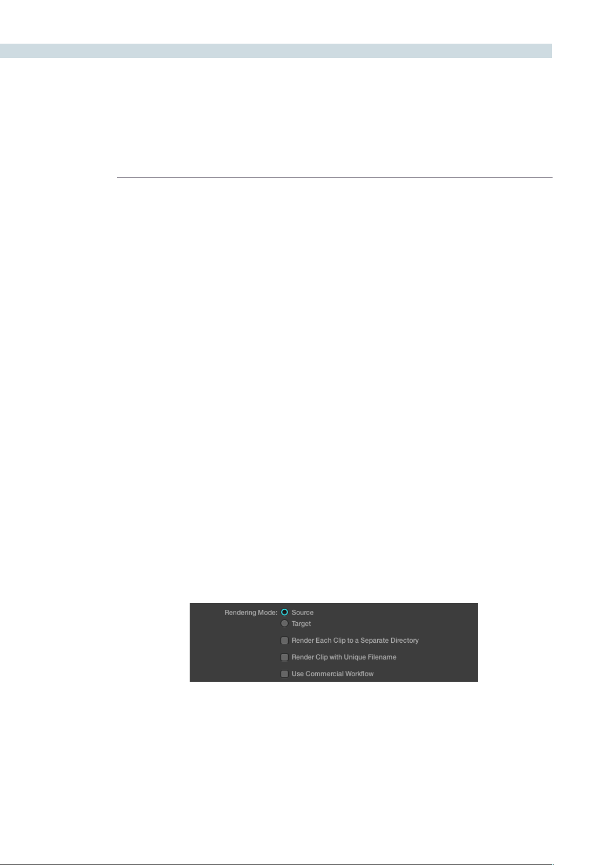
RENDER 372
ThenextsettingistheFrameRateoftherender.Thisnumberistypicallythesameasthe‘Conform’
frame rate as selected on the Config screen, but on occasions you may wish to set this to a variation
of this conformed rate. This will adjust the metadata written within the file and is again to aid playback
for the range of systems available in the market. Use the pull-down to select from the available options.
OutputSizesettingsaresimplytheresolutionforthenishedrenderedle.JustliketheFrameRate
described above, the width and height as defined within the Config screen are automatically displayed
but are still editable. This setting is also guided by the Output Type set in the pull-down just below the
Output Size. Some file formats require specification of the resolution by file type and in this case the
Output Size settings will revert to the fixed format as defined by the standards.
Output Type
This list defines all combinations of file formats, codecs, bit depths, color spaces, and resolutions that
are currently available to be rendered to on your system. The available options depend on whether you
have the Final Cut Pro, QuickTime libraries and the DaVinci Resolve DNxHD Update. Other render file
formats will be added over time, so be sure to check each new version for the latest supported formats.
Rendering Mode
The next section of the Render Properties display manages how clips are rendered, named, and
organized. There are two Rendering modes:
Source mode: Renders each clip as a separate file or image sequence, in ascending
source timecode order. The timecode written to each clip is cloned
from the original source media.
Target mode: Renders the currently selected session as a single, continuous file or
image sequence. The timecode written into each frame will be the
timeline timecode.
The one checkbox option in Target mode is Render Clip with Unique Filename, explained in more
detail below.
When Source mode is selected there are three additional options you can select that determine how
Resolve organizes and names the rendered files.
Selecting Source or Target Recording Mode
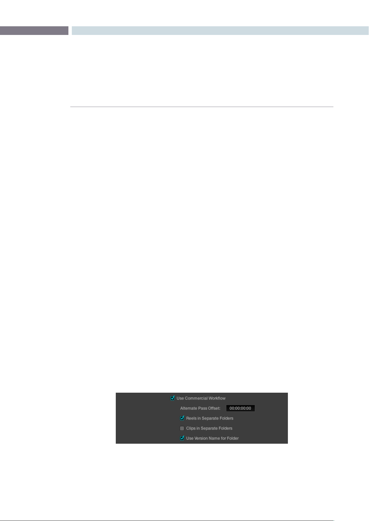
CHAPTER
RENDER
RENDER373
16
Render Each Clip to a Separate Directory:
Remembering these are source clips with their timecode. This is
commonly used when rendering VFX shots for further post work
to allow the VFX department to identify clips quickly and distribute
the work.
Render Clip with Unique Filename:
When enabled, every rendered clip is given a completely independent
name in order to prevent multiple rendered clips from the same
source media file from overwriting one another when saved to the
same directory. “Uniquely” named clips incorporate the track and
clip number of a clip’s position within a session into the name. When
the “Use Prefix, Suffix, No. of Digits from Source” checkbox is also
turned on, the original name of the source media can be combined
with this session information. For example, a clip that’s linked to a
media file named “FeistyCU.mov,” and edited as the twenty-fifth clip
on track V2, will be named “FeistyCU_V2-0025.mov” when rendered
to preserve its independence.
Use Commercial Workflow:
Enables additional settings for defining the timecode, organization,
and naming of each rendered media file or image sequence.
Use Commercial Workflow
DaVinciResolve’s‘UseCommercialWorkow’settingdramaticallysimpliesworkingwithversionsof
grades and provide graded versions in a format that is easy for the other departments in a post house
to use.
With‘UseCommercialWorkow’checked,DaVinciResolvewillautomaticallyrenderalternatepasses
pertaining to different versions of grades. This is typical of commercial broadcast workflows where you
have two or more versions of a grade for each scene. Because the source clip has one logical timecode,
regardless of how many graded versions are made, you can’t simply render this clip five times and put
it in the same folder. All of the timecodes and file names would be the same, so you would end up with
one version - the last you rendered.
Commercial Workflow Options

RENDER 374
The‘AlternatePassOffset’timecontrolallowsyoutoseparatethetimecodevalueswrittenintoeach
version with an offset. For example, if the default version is at 01:00:20:00, and you select a 10 minute
offset in the Alternative Pass Offset timecode entry, then the second graded version of the clips will start
at 01:10:20:00, and the third version will start at 01:20:20:00, and so on until all versions are rendered.
You can offset the clips by whatever value you like, but the idea is to make it easy for the editor and VFX
artists to be able to find the versions of each grade. If the clips are shared with the finishing artist, and
they know the alternate passes (the other versions) are 10 minutes apart, or whatever you set, then it’s
easy for them to change the clip version just by adding 10 minutes to the time. To further simplify the
workflow, you can put the separate source reels in separate folders.
Turningonthe‘ClipsinSeparateFolders‘checkboxautomaticallyplacesalternategradesofclipsinto
separatefolders.Turningonthe‘UseVersionNameforFolder‘checkboxlabelseachfolderwiththe
name of the version.
Tip: You can Right-click a clip in the Thumbnail Timeline of the Color or Render screen and rename any
version of a grade. Again, this is to assist a facilities’ workflow when sharing material between suites and
applications.
Including or Excluding Versions in the Render
Ifyouwishtoexcludeaversiontoberendered,simplyselectthe‘RenderDisabled’optionwhenright
mouse clicking on a clip within the Thumbnail Timeline display on the Color screen.
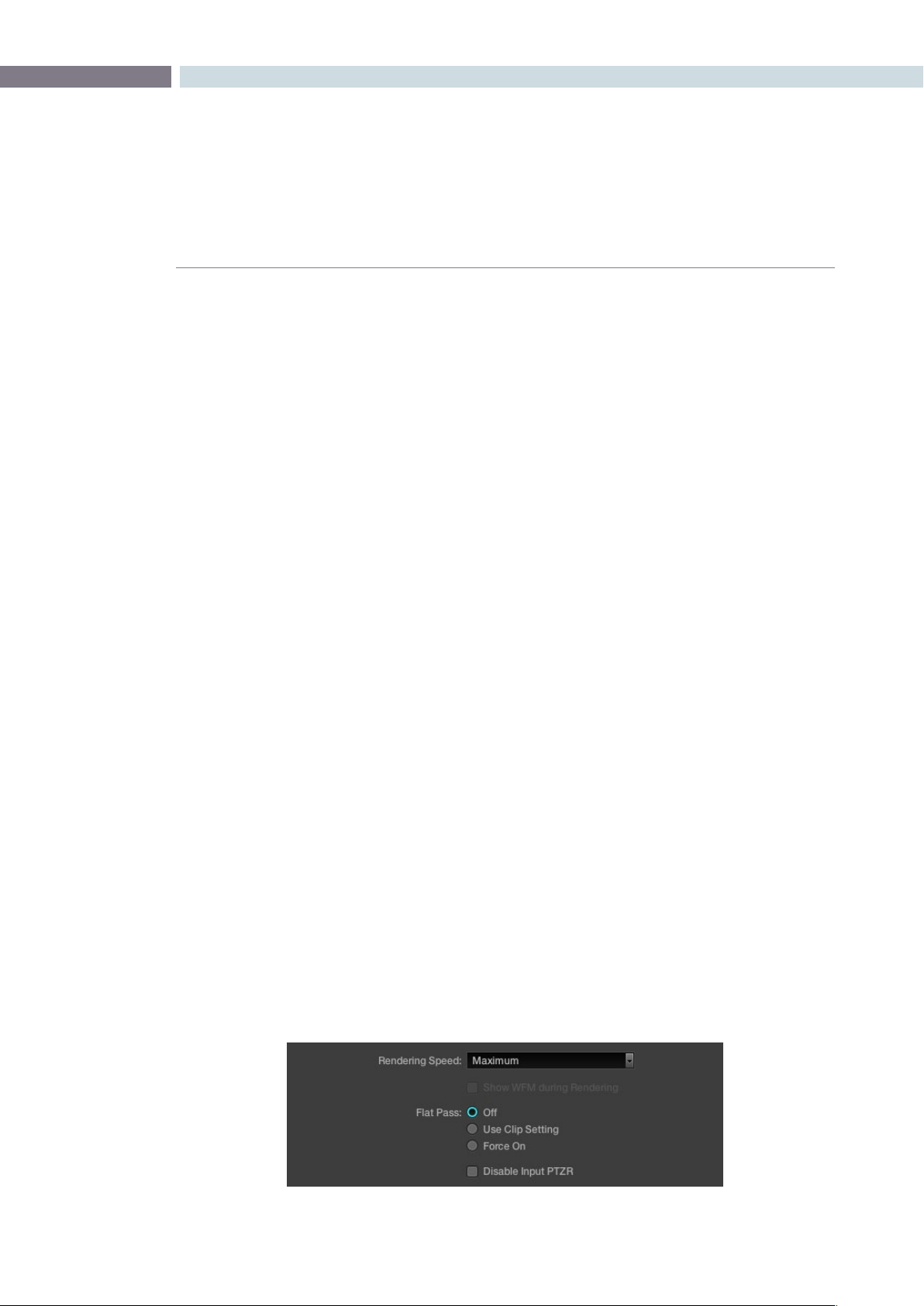
CHAPTER
RENDER
RENDER375
16
Stereoscopic Render
DaVinci Resolve offers stereoscopic 3D operation with all systems, and with the appropriate hardware,
real time grading and playback of two streams of images; the left and right eye. When it comes to
rendering these projects there are two options. For the highest quality render the left and right-eye
sessions separately, creating two sets of full-frame media.
Alternatively, you can turn on the “Enable Stereo Render” checkbox and DaVinci Resolve will render a
single set of media in one of two ways, depending on what you choose from the Mesh options pop-
up menu:
Side by side: Renders a side-by-side image with the left eye on the left-hand
side and the right eye on the right.
Line-by-line: Renders an interlaced blend of both eyes.
Other Render Properties Settings
Some storage systems are shared by multiple applications in a facility and often these storage area
network (SAN) based systems have sufficient bandwidth for only a single stream of images to each
user. With DaVinci Resolve’s super fast render speed this may cause playback problems with other users
on the SAN if the storage bandwidth is insufficient. You can set the Render speed, which is typically set
to Maximum, or throttle down the render speed to limit SAN bandwidth usage to between 1 to 50 fps.
The‘ShowWFMduringRendering’modeupdatestheWaveformdisplayduringRenderingwhenyou
have a separate DaVinci Resolve waveform server. This option is applicable to Linux systems.
Duringrenderingtodiskusing‘CommercialWorkow’,youhavethreeoptionsregardingatpass
control. The settings are:
Off: The system will always apply color correction for all versions of all
clips before rendering to disk.
Use Clip Setting: For each version of a clip, the system will check that version’s pass
flat flag which is set with a right click on the thumbnail. If it is turned
on, the system will disable color correction for that version of the clip.
Otherwise, it will apply color correction for that version of the clip.
Force On: When checked, will force the system to always disable color
correction for all versions of all clips before rendering to disk.
Whenyoucheckthe‘DisableInputPTZR,’anyPan,Tilt,ZoomorRotationswillnotberenderedwith
the material.
Additional Render Properties

RENDER 376
Render Path Settings
TheremainingitemsinthiswindowrelatetotheRenderPathsettings.The‘SourceDirectoryPreserve
Level’ selection will retain the source file directory structure when rendering material. It will automatically
create sub directories to match the source files. This is followed by an indication of the storage use
showing the amount of space available within the target storage area and the new usage based on the
selected timeline or clip for rendering.
Should you use Batch Rendering, there is a progress bar and status display showing the Batch Render
progress, covered later in this chapter. Use the Browse button to select the location, or type it in directly.
Ifyoulike,alsodenea‘DestinationSufx’thatwillbeappliedtotherenderedle.
The‘Render’buttoninitiatestherenderprocessbasedonallthesettingsintheRenderProperties
display. This will bring up a prompt, in place of the Render window, that shows you the progress of the
render. You can watch the Viewer as DaVinci Resolve is rendering and note the render speed on the
top left of the Viewer. A Render Progress window will also be displayed on the Color screen during the
render. Should you wish to interrupt or cancel the rendering process and close the Record Properties
window, select the ’Cancel’ button.
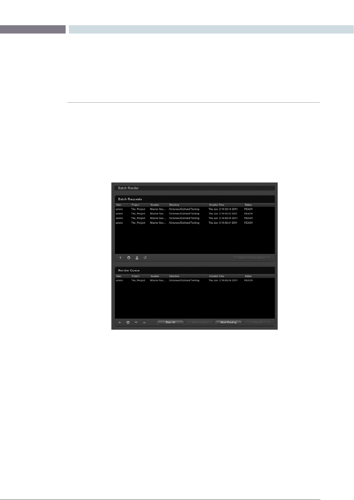
CHAPTER
RENDER
RENDER377
16
Batch Render
DaVinci Resolve offers the ability to set up multiple render configurations and make a Batch Render list.
No renders are actually made from this list, however it is useful for render management and allows you
to set up different resolution, file type, and path settings as batch requests.
The Batch Render list shows configurations set in the Render Properties display. After you have made
allthesettingsforarender,insteadofstartingtherender,usingthe‘Render’button,youcanaddthese
settingstothe‘BatchRequest’list.Usethe+toaddrequestsand-todeletethem.Thelocksymbolis
used to avoid accidental changes to the settings of requests in the list and the refresh symbol to update
the list.
If you select and highlight an event within the Batch Request list you will notice that the properties on
the left side of the screen, the Render Properties, will all update to those saved in that batch request. If
you have selected an item in the Batch list you can then start a render using the Render button, or use
‘AddtoRenderQueue’toputthiscongurationintotheRenderQueuejustbelowtheBatchRequests
list. This will remove the item from the Batch list.
Batch and Render Managers
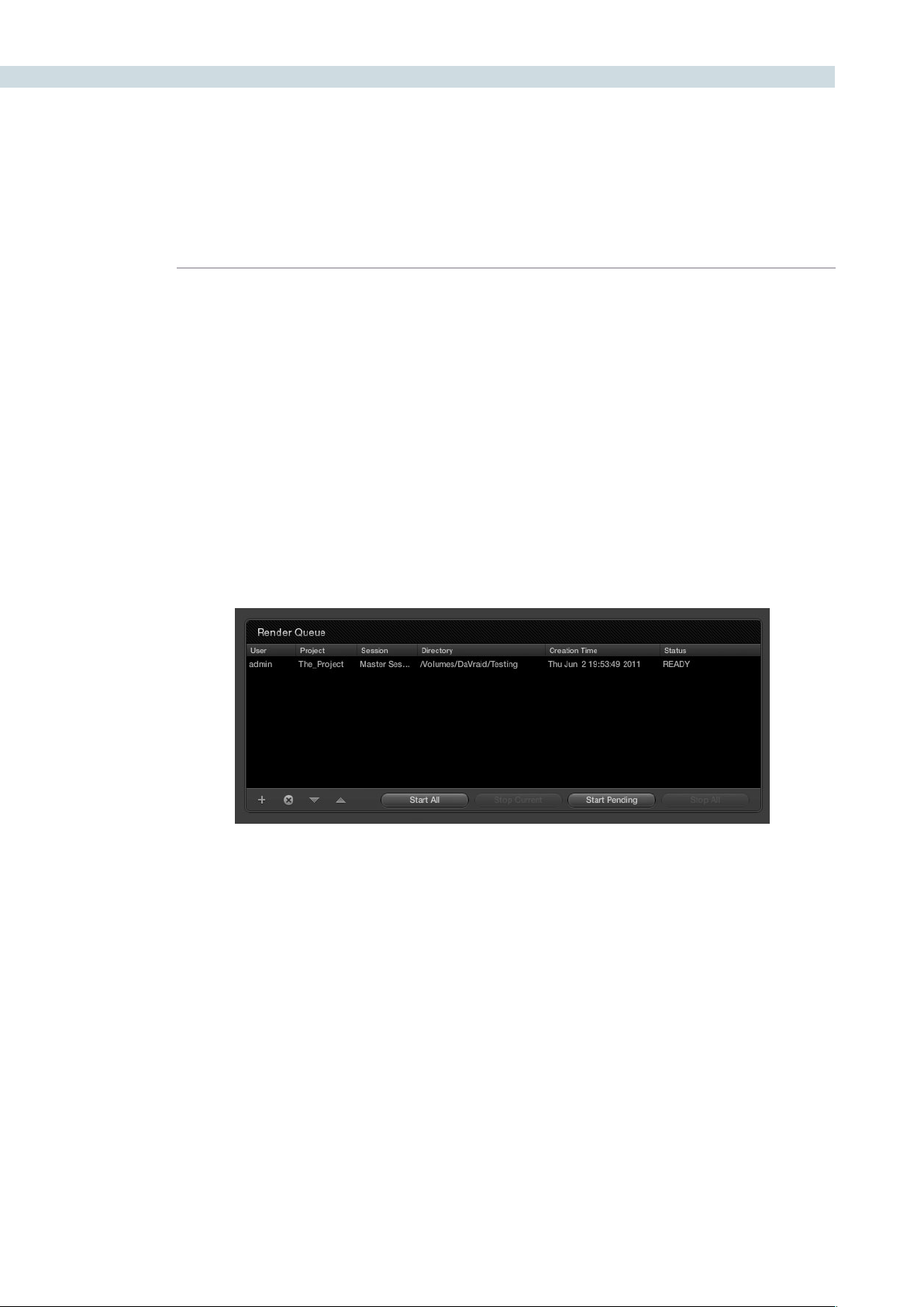
RENDER 378
TheRenderQueueallowsyoutocreateofaqueueofcongurationstoberendered.Clickingon+will
addtheinformationintothequeuefromthe‘RenderProperties’displayand-willremoveitfromthe
queue.Asdescribedabove,usingthe‘AddtoRenderQueue’buttonwillmoveaBatchRequestitems
into the Render Queue.
All items added to the queue are placed at the bottom of the list. Use the up and down arrows to move
the priority of the event in the list. You can select queued items, which update the Render Properties
display,andthenselectthe‘Render’button,oryoucaninitiatetheRenderQueue.Selecting‘StartAll’
will begin rendering of all the items, one at a time, in the Render Queue. The status display on the right
of the Render Queue window will show you the status of each event.
The‘StartPending’buttonwillinitiatearenderofallclipsinthequeuethathavenotalreadybeen
rendered.Thisisslightlydifferenttothe‘StartAll’functionwhichwillre-renderallclipsinthequeue,
regardless of if they have already been rendered or not. You can stop the current event from rendering
andDaVinciResolvewillthenproceedautomaticallytothenextevent,oryoucanselect‘StopAll’to
cancel all renders. The list will remain active so you can start again later, or modify and start again.
Render Queue
Render Queue


17
Stereoscopic Grading

CHAPTER
STEREOSCOPIC GRADING
STEREOSCOPIC GRADING381
17
With DaVinci Resolve on Mac systems, dual 4:2:2 Y’CbCr stereoscopic video streams are output via HD-
SDI on the Blackmagic DeckLink HD Extreme 3D card. You can select either Side-by-Side or Line Mesh
output to be fed to your stereo-capable display, depending on what it’s compatible with.
Note: If you turn on the Enable Dual SDI 3D Monitoring checkbox on the Settings tab of the Config
page, the DeckLink HD Extreme 3D will output full resolution 4:2:2 Y’CbCr for each eye.
When setting up a 3D-capable Resolve workstation, keep in mind that the dual video streams of 3D
projects make greater demands on disk bandwidth, media decoding via CPU or RED Rocket, and
effects processing via GPU.
On Linux systems, stereoscopic performance is similar to that of a qualified Mac Pro with the same
number of GPUs. Similarly to the Mac Pro, stereo is output via HD-SDI on a Blackmagic DeckLink HD
Extreme 3D card using either Side-by-Side or Line Mesh output.
Linux systems have greater GPU expandability, offering the possibility of greater stereoscopic
performance,andsupportforupto4:4:4RGBorXYZmonitoringatHDresolutionforeacheye..
Creating a Stereoscopic Project
Working on stereo in DaVinci Resolve requires very specific project setup. You can create the necessary
pair of stereoscopic sessions from an edited EDL by either preconforming two flattened media files,
one each for the left and right eyes, or by conforming two sets of discrete media files that have been
carefully organized. Either way, you can use the following procedure to create a stereoscopic project.
To create a stereoscopic project:
1. In the Browse page, create two Media Pool subfolders (one for each eye), and name
them “Left” and “Right.”
2. When importing the stereo media used by your project, place all left eye files in the
”Left” folder and all right eye media in the ”Right” folder.
Tip: Non-3D projects can be converted to 3D projects at any time, simply by adding the
second eye media in its own Media Pool sub-folder.
3. Open the Conform page, and create the default timeline in the Conform screen.
4. Now, load an EDL or use Pre-Conform to create a session, and you’ll be automatically
prompted to select one one of the Media Pool sub-folders you created in the first step.
Create two sessions, one using the media in the “Left” folder, and one using the media in
the “Right” folder.
5. Now, choose the session that uses the left-eye media, right-click anywhere within the
Conform timeline and choose Stereo Left Eye. That session is now the left-eye stereo-
identified session.
6. Select the session that uses the right-eye media, and similarly right-click in the Timeline
and choose Stereo Right Eye to make it the right-eye stereo-identified session.
At the end of this process, you have two matching stereo-identified sessions, and you’re ready to
begin grading.
Stereoscopic Grading

STEREOSCOPIC GRADING 382
Choosing Which Session to Grade
Because each “eye” corresponds to an individual session, whichever session you select in the Conform
page is the eye that you’ll be grading. Most colorists work by grading one eye first (typically the left), and
rippling their grades to the other eye, making separate adjustments to each eye’s clips when necessary
to match undesirable variation between cameras.
When you open the Color or Format pages with a stereo-identified session selected, you’ll notice that
theclipsintheThumbnailTimelineoftheColorandFormatpagesaredisplayedwithanL+Ricon.This
happens because, by default, the Stereo > Ripple Link submenu is set to Gang, meaning that every
correction you add to one eye is automatically applied to the other. If you right-click on the Thumbnail
TimelineandsetStereo>RippleLinktoSolo,theL+Riconsdisappear.
To help you keep track of which stereo-identified session you’re working on while in Stereo > Gang
mode,theL+Riconsoftheleft-eyesessionarered,whiletheL+Riconsoftheright-eyesessionarecyan.
Tip: You can also change which eye you’re grading by right-clicking the Viewer and choosing
Stereo > Switch Eye from the contextual menu. The available Stereo commands are described in more
detail later in this section.
Monitoring Stereoscopic 3D
To output both eyes to a stereo display, you need to turn on the “Display Both Eyes For 3D” option in the
Viewer’s contextual menu (within the Color, Viewer, or Format pages), and then choose a display mode
from the 3D Display Options submenu.
Additionally, the Viewer itself (in the Color, Viewer, and Format pages) can be set to display both “eyes”
in one of a variety of different modes.
To monitor both eyes:
1. Right-click in the Viewer, and choose “Display Both Eyes For 3D” from the
contextual menu.
This menu option has a checkbox that’s turned on when this mode is active. When
turned on, both eyes are output to your external display. A checkbox in the Settings tab
of the Config page, “Enable dual SDI 3D monitoring,” determines how stereo is output.
When turned on, full resolution video frames for each eye are output via both HD-SDI
channels. When turned off, both eyes are output from a single HD-SDI channel as a
stereo mesh.
2. Right-click the Viewer again, and choose “Apply 3D mesh to GUI display” to actually
see both eyes within the Viewer of the Color and Viewer pages.
“Apply 3D mesh to GUI display” and “Apply 3D mesh to WFM display” are only visible
when “Display Both Eyes For 3D” has been turned on.
3. Choose a 3D Display Option:
Side by Side: Displays both images side by side. Each eye is squeezed
anamorphically to fit both eyes into the same resolution as the
GUI viewer.

CHAPTER
STEREOSCOPIC GRADING
STEREOSCOPIC GRADING383
17
Line by Line: An interlaced mode where each eye is displayed on alternating lines.
The thickness of the lines as displayed in the GUI viewer depends on
how zoomed in you are.
Checkerboard: Displays both eyes via an alternating checkerboard pattern. This
is an excellent mode for identifying individual regions of color or
geometry variation within a 3D shot.
Anaglyph (B/W): Each eye is desaturated and superimposed via Red/Cyan anaglyph
to show the disparity between both eyes in different regions of the
image. Left-eye divergence is red, and right eye divergence is cyan.
Regions of alignment between both eyes appear grayscale.
Anaglyph modes are useful for evaluating the geometric differences
between both eyes, as well as for identifying the point of convergence
(where both eyes align most perfectly) that places a region within
the image at center-screen depth, with regions of greater disparity
projecting farther forward and backward from that point (seen as a
greater separation between the red and cyan-colored eyes).
Red/cyan color-coding also identifies the direction of projection. For
any given feature, disparity such that red is to the right and cyan is
to the left indicates backward projection. Red to the left and cyan to
the right indicates forward projection.
Anaglyph (Color): Similar to Anaglyph (B/W), except that regions of close alignment
are shown in full color. Incidentally, both anaglyph modes can be
previewed on ordinary displays using old-fashioned red/cyan
anaglyph glasses, to provide that 1950’s retro experience.
Difference: Superimposes grayscale versions of both eyes using the difference
composite mode. Corresponding left/right eye pixels that are
perfectly aligned appear black, while pixels with disparity appear
white. This mode is extremely useful for evaluating geometric
differences between both eyes, as well as for identifying the point
of convergence, without the distraction of color that the anaglyph
modes present.
None: Only displays the eye corresponding to the currently selected
session. When “Enable dual SDI 3D monitoring” is turned on in the
Settings tab of the Config page, each eye remains output to each
HD-SDI channel.
4: To turn stereo display off, right-click in the Viewer, and choose “Display Both Eyes For
3D” from the contextual menu again.
The “Apply 3D Mesh Display...” and “3D Display Options” settings don’t change when
stereo display is toggled on and off.

STEREOSCOPIC GRADING 384
Grading Stereoscopic 3D
This section covers the various commands and parameters that are available to help you manage
grades in stereoscopic projects.
Stereo Batch Modes
There are two Batch modes that are used for stereoscopic grading that are available when you right-
click a clip in the Thumbnail Timeline:
Stereo Batch Copy: Copies every grade from one stereo-identified session to the
correspondingly numbered clips in the other, for example from
the Left-eye session to the Right-eye session).
Stereo Batch Sync: Copies grades from one stereo-identified session to the other
only when their Node Graphs have the same number of nodes.
This prevents you from accidentally overwriting a custom grade
with a different node structure that was necessary to match two
eyes for a problem shot.
There’s also a set of commands, found in the Stereo submenu when right-clicking a clip in the Thumbnail
Timeline that provide a variety of stereoscopic functionality.
Copy Grade: Copies the current grade to the correspondingly numbered shot
of the other stereo-identified session.
Swap Grade: Swaps the grades between correspondingly numbered shots in
left and right-eye sessions.
Swap Shots: A checkbox that, when enabled, switches the actual media used
by two correspondingly numbered shots in left and right-eye
sessions. Useful in situations where the eyes of a stereo clip were
mis-labeled, and you want to switch the clips without rebuilding
both EDLs.
Ripple Link: When the you set Stereo > Ripple Link to Solo, grades made
to clips in the current session are made independently of the
corresponding stereo-identified session. When set to Gang, all
grades you make to a clip in one session are automatically copied
to the correspondingly numbered clip of the matching stereo
session, keeping the grades of the left and right-eye sessions the
same. You can turn Ripple Link Solo to suspend rippling when
you want to make an individual adjustment to the grade of one
eye, and then turn it back to Gang when you want to resume
automatic copying.
Switch Eye: Selects the session to the other eye, without the need to go to
the Conform page. To help you keep track of which eye you’re
workingon,theL+Riconsinthethumbnailsoftheleft-eye
sessionsarered,whiletheL+Riconsinthethumbnailsofthe
right-eye sessions are cyan.
Important: For all of these commands, local versions created for a clip in one stereo-identified session
are automatically copied to the other.

CHAPTER
STEREOSCOPIC GRADING
STEREOSCOPIC GRADING385
17
Protecting Stereo Adjustments When Copying Grades
Independentstereoadjustmentsarestored,alongwiththePTZRsettings,foreachversion;3Dand
PTZRsettingsareprocessedpriortonode-basedcorrectionsintheResolveimageprocessingpipeline.
To prevent accidental overwrite of convergence and alignment data when copying grades, you can
Right-click in the Stills or Powergrade tab of the Color or Gallery pages and choose “Copy Grade:
Preserve Stereo Adjustments.”
Whenever you copy a grade to any clip, having this option enabled lets you overwrite the color
parameters of that clip’s current version, without overwriting its 3D parameters.
Stereo Status Display on the Color Page
There are three status display items in the Color page that let you keep track of which stereo-specific
modes are currently in use.
Convergence: Shows the currently enabled Convergence mode. The two
possiblemodesareOppositeandLinkedZoom.
Stereo Grade: Shows which stereo-identified session you’re currently grading,
and whether or not Ripple Link is set to Solo or Gang mode.
Stereo Display: Shows whether Display Both Eyes for 3D has been turned on in
the Viewer, either Mono or Stereo.
Convergence
The Convergence slider, in the input tab of the Format page, adjusts the disparity between the left and
right eyes. You use this slider to define the point of convergence (POC), or the region where the left
and right eye clips are in perfect alignment. The POC defines the part of the picture that appears to be
aligned with the glass of the monitor itself. In the process, you also define the regions of the image that
project forward and backward from the screen.
There are two modes for making Convergence adjustments, you select which one to use by right-clicking
within the Thumbnail Timeline and choosing one of two options from the Stereo > Convergence submenu:
Opposite: In this mode, the convergence control moves the images left
and right to change the point of convergence.
Linked Zoom: In this mode, Resolve automatically zooms both eyes by the
appropriate amount so that both eyes always fill the screen, no
matterwhatyourConvergencesettingis.ChoosingLinkedZoom
alsoturnsonthe“LinkedZoom”checkboxintheFormatpage.
PTZR Repositioning in Stereo
Generally,you’llwanttorepositionstereoclipsusingthePTZRparametersGangmode,butyou
may occasionally find yourself needing to make a manual adjustment to one eye in particular
inSolomode.Aswithcoloradjustments,PTZRadjustmentsinSolomodeareonlyappliedto
theclipinthecurrentsession.InGangmode,allPTZRadjustmentsareautomaticallycopied
to the correspondingly numbered shot of the other stereo session.

STEREOSCOPIC GRADING 386
Automatic Color and Geometry Matching
DaVinci Resolve has a set of auto-matching features that are designed to help you skip some of the
tedium of dealing with mismatched color and geometry between the left and right eye media for each
shot. These features are designed to
Stereo Color Match
Due to the design of different stereo rigs, it’s sometimes the case that the color and contrast of one eye’s
media doesn’t precisely match that of the corresponding eye. DaVinci Resolve provides two commands
for quickly and automatically matching two eyes together.
Primary Controls: Uses the Lift/Gamma/Gain controls to match one eye to the
other. The result is a simple adjustment that’s easy to customize,
but may not work as well as Custom Curves in some instances.
Custom Curves: Uses the Custom Curves to create a multi-point adjustment
to match one eye to the other. Can be more effective with
challenging shots.
Tip: For the best results, it’s recommended to use automatic color matching in a separate node,
independent of other corrections.
Stereo color match works differently depending whether or not there are already adjustments already
made to one of the eyes. The following procedure shows how to match a pair of left and right eye clips
if there are no adjustments at all, prior to beginning your grade.
To automatically match the left and right eye media of one or more clips:
1. Select one or more clips in the Thumbnail Timeline of the Color page.
2. Right-click one of the clips, and choose one of the two options from the Stereo Color
Match submenu.
The Color Matching window appears, and a progress bar shows the remaining time this
operation will take.
You can also use automatic color matching to match an ungraded clip in one stereo session to its
previously graded (in Solo mode) matching eye. This only works for primary grades, secondary
operations cannot be auto-matched.

CHAPTER
STEREOSCOPIC GRADING
STEREOSCOPIC GRADING387
17
To automatically match one eye to another, independently graded eye:
1. Right-click the Thumbnail Timeline, and choose Stereo > Ripple Link > Solo.
2. Make a primary adjustment to a clip in the Left-eye session to create a simple
base grade.
3. Right-click the Thumbnail Timeline again, and choose Stereo > Switch Eye.
This only works if you use the Stereo Color Match commands on an ungraded eye, to
match it to the graded eye.
4. Now, Right-click the Thumbnail of the clip you want to match, and choose one of the
two options from the Stereo Color Match submenu.
You can also use the above procedure to match a selection of multiple graded clips with their
corresponding left or right-eye counterparts.
Stereo Align
For the stereoscopic effect to work without causing headaches, it’s critical that both eyes are vertically
aligned. This can be tricky to adjust using manual controls, but can be automatically analyzed. In
particular, you can select an entire range of clips to automatically align all of them at once.
To automatically align one or more clips:
1. Select one or more stereo clips in the Thumbnail Timeline of the Color or Format pages.
2. Right-click the thumbnail, and choose Stereo Align from the contextual menu.
The Stereo Alignment window appears, and a progress bar shows the remaining time
this operation will take.

STEREOSCOPIC GRADING 388


18
Remote Grading

CHAPTER
REMOTE GRADING
REMOTE GRADING391
18
To enable colorists to work interactively with their clients across the globe, DaVinci Resolve offers a
remote grading option. It allows two matching DaVinci Resolve systems to be synchronized via an
Internet connection such that changes made on the colorist’s system are immediately sent across and
applied on the client DaVinci Resolve.
Cue commands are also synchronized to ensure that both systems are always on the same frame in the
timeline. Starting/stopping playback on the colorist’s DaVinci Resolve would do the same on the client
system. While a remote grading session is in progress, inputs from the user at the client DaVinci Resolve
will be ignored.
Currently, the remote grading feature supports only color correction and does not allow editing or
conforming during a session. The two DaVinci Resolve systems must have matching sessions and the
number of clips, clip durations and system resolutions must match. The requirements and limitations of
a remote grading session are summarized below.
Requirements
•TheDaVinciResolveversionofsoftwaremustbethesameonbothsystems
•Thesystemresolutionmustbethesameonbothsystems
•Thetimelinemustbesetuppriortothestartoftheremotegradingsession.
•Thenumberofclipsandthedurationofeachclipmustbeidentical.
•Duringthesession,theactivesessionandversionsontheclientsystemareupdated.Creating/
deleting a session or switching a session on the colorist’s DaVinci Resolve is not allowed. Doing so
would terminate the remote grading session.
•Ontheclient’sDaVinciResolveyoucannotadjustanythinguntiltheremotegradingsessionhasended.
Setup
•Tostartaremotegradingsession,theclientDaVinciResolveshouldbeabletoconnecttothe
colorist’s system using TCP/IP.
•Ontheclient’sDaVinciResolveyouneedtopressCtrl+Gonthekeyboard.Awindowisdisplayed
with text fields to enter the IP address and port number of the colorist’s system.
•SettheIPaddresseldtotheIPofthecolorist’sDaVinciResolve.Ifthecolorist’ssystemisona
public IP, the port number can be left at the default value (15000). If the colorist’s system is on a
private network, the port number should be set to the port on the public IP that is internally routed
to port 15000 of the colorist’s DaVinci Resolve.
•Oncetheclientclicksonthe“Connect”button,theclientDaVinciResolvewilltrytoestablisha
connection with the colorist system.
•Whentheconnectionisestablished,apopupappearsonthecolorist’sscreenaskingforpermission
to accept the Remote Grading connection.
•Toaccept,click“OK,”minimizethepopup,andcontinuegradingnormally.
The Remote Grading session will remain active until one of the users chooses to disconnect or when an
error occurs causing DaVinci Resolve to automatically terminate the session.
Remote Grading

REMOTE GRADING 392
Restrictions
To allow operation over low bandwidth and potential long latency Internet connection there are some
restrictions to remote operation.
•Grabbingstillsonthecolorist’sDaVinciResolvewillnothaveanyeffectontheclientsystemsono
stills will be grabbed on the client system.
•Wipesonthecolorist’ssystemwillhavenoeffectontheclientDaVinciResolve.Atanytime,the
client system will display the same frame as the colorists but without the wipe (or with whatever
wipe was enabled before the remote grading session was started).
•Whenplaybackisstarted,theplaybackspeedsonthetwoDaVinciResolvesmaydiffer.Theframe
positions will only be synchronized when playback is stopped.
•Input/output/displayLUTsappliedfromthecongpageonthecoloristDaVinciResolvewillnothave
any effect on the client system. LUTs selected on the client DaVinci Resolve will be applied instead.
•Presetsappliedfromthecong/colorpagesonthecoloristssystemwillnothaveanyeffectonthe
clients. Presets selected on the client DaVinci Resolve will be applied instead.


19
DaVinci Resolve Control Surface
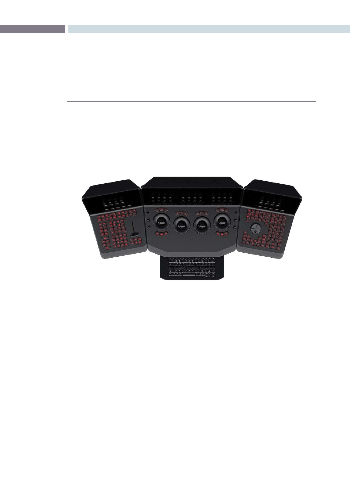
CHAPTER
DAVINCI RESOLVE CONTROL SURFACE
DAVINCI RESOLVE CONTROL SURFACE395
19
The DaVinci Resolve Control Surface panels feature workflow ergonomics and ease of use so Colorists
can quickly and accurately construct simple or complex creative grades. The panels feature high-
resolution liquid crystal displays (LCD) and backlit hard keys to accommodate a darkened grading
environment. The color and intensity of the keys and the LCD panel brightness are user programmable
so each Colorist can set up his/her personal panel configuration.
There are three panels in the control panel set. The center panel is the Trackball panel. The majority of
controls and feedback for the Colorist is found on this panel, including a slide-out keyboard.
On either side of the Trackball panel are two interchangeable panels, the position of which is determined
by operator preference. The T-bar panel, shown above on the left, has a T-bar mix/wipe control and a
number of menu and function keys. The Transport panel, shown above on the right, has the timeline
transport controls and a jog/shuttle control as well as a numerical keypad and associated function keys.
All panels have soft keys and variable control pots within the LCD panel, which provide an accurate
visual reference to the control without the risk of parallax errors. Given that so many of the controls are
menu based, this User Manual will describe each of the hard keys and controls and then, separately, the
menu structure and controls of the soft keys and variable pots.
A key feature of the panel design is the feedback given to the Colorist. The LCD panels provide a
color and value indication based on the last control adjusted. The hard keys also reflect the last button
pushed and, in some cases, other keys on the panel are illuminated or dimmed based on the menu
options available for the operational mode selected.
Shift Key Convention
Before describing the hard key operation, it is important to understand two keys on the left and right
panels. These shift keys, Shift Up and Shift Down, provide access to potentially two more functions on
each of the next key selected.
DaVinci Resolve Control Surface
DaVinci Resolve Control Surface

DAVINCI RESOLVE CONTROL SURFACE 396
Forexample,ontheFaderpanel,nexttotheshiftupkeyistheBaseMemkey.Ifyouselect‘ShiftUp’
andthen‘BaseMem,’theoperationistoBaseMemALL,asdesignatedontheupperleftcornerofthe
BaseMemkey.ToselectBaseMemCurrent,rstselect‘ShiftDown,’then‘BaseMem.’Topermitafast
andsingle-handedoperation,thisfunctiondoesnotrequireyoutoholdthe’ShiftUp’or‘ShiftDown’
keywhileselectingthesecondkey,justselectthemsequentially,rstthe‘Shift’key,thenthefunction.
T-Bar Panel
The T-Bar Panel, typically located on the left for a right-handed Colorist, has a LCD display with four
variable controls and nine soft keys. The lower section of the panel houses the T-bar and six groups of
hard keys.
While the soft menus, keys, and variable pots will be covered in a later section of this chapter, here is a
description of the groups of keys and the individual key function.
Mode Control Group
The Mode Control group provides navigation to many of the UI screens and also a few commonly
used functions.
Config: This key selects the configuration UI screen where you will set
up DaVinci Resolve for each project.
Browse: On the Browse screen you can review files on the attached
storage, or if you have a storage area network, you can directly
access the SAN. You can see details of each file, play the clips
for verification, and then associate them to the Project by
putting them into the Media Pool.
VSR (Shift Down Browse): This selection is reserved for future use.
Conform: Selects the Conform screen. After placing the Project’s clips
into the Media Pool, you will generate a default timeline and
associate EDLs in this screen.
Deck (Shift Up Revival): The Deck key selects the screen for deck I/O. This same
screen is used to control a batch capture of clips from some
film scanners.
Revival: This key opens the DaVinci Revival screen to show the files
selected to be sent to a DaVinci Revival system for Grain
reduction or Dust busting.
Scene (Shift Down Revival): To select the Scene Cut Detection screen select the shift down
key followed by the Revival key.
Current ~ Viewer: This key toggles between the screen you are on and the Viewer
screen so it’s a quick way to see the image at full screen on the
UI display.
Object Track Mode: The Object Tracker is best viewed on the Viewer UI. This key
selects this screen and also opens the Object Tracking menus.

CHAPTER
DAVINCI RESOLVE CONTROL SURFACE
DAVINCI RESOLVE CONTROL SURFACE397
19
Clip/Track/Unmix: This is a toggle key. The color corrections in DaVinci Resolve
are generally associated to each individual clip and so most
ofthetimeyouwillbein‘Clip’mode.Occasionally,youmay
wish to make a grade or correction, enhancement, or even add
amattetothewholetimeline.Inthiscase,select‘Track.’The
‘Unmix’functionallowspre-conformedclipswithdissolvesto
be un-mixed when using an EDL. Then each clip can be graded
separately as though there were two clips.
User (Shift Up Cache Mode): Will mark a clip for render cache.
Cache: This key is a toggle function to select one of the cache modes.
Cache All will background cache all clips.
This operation in performed when you move from the current
clip to another. Dissolve will cache clips with dissolves. User
will cache clips as marked by the colorist. User & Dissolve will
cache clips that you have marked for cache and also dissolves.
Editor: The Editor key is reserved for future use.
Proxy On/Off: DaVinci Resolve has three proxy modes to permit real time
playback in the event that the correction or resolution is too
highfortheselectedplaybackspeed.With‘Pre-generated
Proxy’ the system will use the pre-generated proxies (obviously
youneedtohavemadetheproxiesrst).Thelastmodeis‘OFP’
or‘On-the-y-Proxy.’OFPprovidesahigh-qualityrealtime
inputimageresize.The‘ProxyOn/Off’keyselectsbetween
Off and the other of the two modes, depending on whether
you have or have not pre-generated the proxies.
Auto Color: This is a popular key. Using this key, DaVinci Resolve will
automatically make a basic primary color correction to balance
the blacks and whites of your image.
Page Up (Shift Up Gallery): In larger projects you may have a number of gallery pages
holding stills and this key will change the Gallery screen to the
next higher page number.
Gallery: Used to select the Gallery UI screen where you can manage
your stills.
Page Down (Shift Down Gallery): The inverse of the Shift Up Gallery function as this selects the
Gallery screen one page lower than the current.
A/C Mode: This toggle key will display the clips in the timeline in the order
of the EDL (the record order and often referred to as C Mode),
or the ascending order of the source clip timecode called
A Mode.
Handles Mode: This selection is reserved for future use.

DAVINCI RESOLVE CONTROL SURFACE 398
Session Management
When making a grade to clips, colorists often try different looks. This group of keys offers a quick way
to navigate through these versions and also to split and join clips on the timeline.
Split (Shift Up Undo): This key will split the clip at the position of the cursor on
the timeline.
Undo: Undo is one of the favorite keys of colorists. Try any grade, and
if you don’t like it, simply Undo. In fact, you have an almost
endless tree of undo operations by using this key.
Join (Shift Up Redo): The reverse of split. Place the timeline cursor on the junction
oftwoclipsandselectJointomakejustoneclip.
Redo: Sometimes you hit Undo once too many times. Redo will put
back into effect the last item you undid. Like Undo, there are
multiple levels.
Restore Point: This selection is reserved for future use.
Save: Remember this key. It’s your friend. Save often, and consider
the autosave function as well; found in the config screen.
Add Version: When you make a grade on any clip, DaVinci Resolve stores
the parameters for that clip. If you want to try different grades,
don’tlooseyourgoodgrades,just‘AddVersion.’Usethiskeyto
make a second, third, or more version of the grade for that clip.
Default Version: If you have multiple versions of grades for a clip, this key is
used to select the default version, regardless of which version
is currently displayed.
Previous Version: This will select the grade one version lower in order. For example,
youareonversionthree,select‘‘PreviousVersion’togetto
version two. Once the default version is reached, selecting
‘PreviousVersion’againwillselectthehighestversion.
Next Version: Use this key to select the next higher version of the grade.
Oncethetopversionisreached,selecting‘NextVersion’again
will select the default version.

CHAPTER
DAVINCI RESOLVE CONTROL SURFACE
DAVINCI RESOLVE CONTROL SURFACE399
19
Marking Dynamics
On the bottom right of the Color screen is the Dynamics Timeline display for the current clip in the
timeline. The Marking Dynamics group of keys is used in association with the Dynamics timeline and
controls the selection of keyframe points for the start and end of dynamic transitions of the grade.
Start Dynamic: This key is used to select the first keyframe in a transition, a
Dynamic. The transition may be a grade change, a sizing, and
the addition of a matte or any number of 100 variables, all of
which are associated with the Node Graph and the Clip or
Track Dynamics Timeline.
Ripple Value: If you have a grade, or effect, or just an adjustment and you
would like to ripple this effect over another or a large number
of other clips, use Ripple Value.
Delete: This key deletes the dynamic.
Lift Mark: If you place a mark in the wrong spot, put your cursor on the
markanduse‘LiftMark’toremoveit.
Trim: This key is used with the numerical keypad to trim a
mark position.
Mark: Like the Start Dynamic key, Mark is a major key. It places a
keyframe on the clip timeline and between the Start Dynamic
and Mark, or between multiple Marks where you can change
the grade.
Scene (Shift Down Mark): This selection is reserved for future use.
Memory Access
DaVinci Resolve has a number of hot keys where you can store a grade for quick reference of use, called
Mems. In fact, every time you make a grade for a clip, a memory of the grade is kept. (facilitates ’Undo’
and ’Redo’). While you can obviously save a still for each clip, having 1000s of stills to scroll through can
taketime,sothereare26quickandeasymemorylocationstostoreagrade,calledA-ZMems.
As every clip has its own metadata for the grade, this is stored by DaVinci Resolve as a Memory too.
There are a number of keys to select or revert to these stored metadata memories, or to clear the
metadata to revert to a base grade, or no grade, state.
All Base Mem (Shift Up Base Mem):
This is used to clear the current color correction of every node
in the Node Graph for the current clip, but it leave the nodes
in place.
Base Mem: Used to clear the grade of the current node.
Current Base Mem (Shift Down Base Mem):
Will clear all the grades and all the nodes of the current clip.

DAVINCI RESOLVE CONTROL SURFACE 400
There is an exception to rule to clear the Base Mem. It is possible, in fact very helpful sometimes, to have
a preset to a clip that is not cleared when you select Base Mem. The simple example is when a film is
over scanned and the frame edges are shown as well as the image. Instead of making an input resize
adjustment for every clip to remove the framing, a preset resize can be made and stored, with a label,
and this preset is not deleted when using Base Mem.
Preview Mem: To preview one of the memory grades on any clip, select the
clip on the timeline, select preview memory and then the
memory. This key is a toggle so if you do not like the grade on
the memory for that clip, select preview mem again and the
clips grade will revert to the original.
Original Mem: Each clip, by default, has a memory of its grade, sizing, etc.
The metadata for every clip is saved in reference to the source
timecode. If you are grading a clip and move from it to another
clip, the grade is saved in a memory for that clip automatically.
If you come back to the clip and make a change to the grade,
then decide you don’t like the change, select Original Mem to
return to the grade status you found when returning to the clip.
Scroll: When you select Scroll you can navigate up and down the
timeline to find and select a clip, and its grade, to recall to the
current clip.
View(Shift Up Current): The Color screen has two display modes. The normal mode
includes the Viewer, Stills and Node Graph on the top of the
screen.Selecting‘View’togglestothealternatescreenwitha
wideNodeGraphviewandStillsbutnoViewer.Select‘View’
again to toggle back to the normal mode.
Current: Select Current prior to selecting a Mem key (A, B, C to X) and
the current grade on the active timeline clip will be stored in
the memory selected.
Shift Up: The Shift Up key permits the operator to select the upper
secondary function of keys on the control panel. This operation
does not require you to hold the shift up key, just select it prior
to the second key.
Shift Down: The Shift Down key permits the operator to select the lower
secondary function of keys on the control panel. This operation
does not require you to hold the shift up key, just select it prior
to the second key.
Macro: This key is not yet implemented.
Memory Keys: The A, B, C to X keys, selected directly or with the appropriate
shift up or shift down pre-selection will recall the grade stored
in this memory and will apply it automatically to the clip that is
active on the timeline.

CHAPTER
DAVINCI RESOLVE CONTROL SURFACE
DAVINCI RESOLVE CONTROL SURFACE401
19
Menu Navigation and Node Control
DaVinci Resolve is a nodal-based color enhancement system. All grades are not stored in layers, but in
nodes. In operation they can appear to be in layers, if you select the serial nodes, but greater grading
flexibility is available by using the parallel and layer nodes.
This group also gives you quick access to the main operations to control primaries, secondaries known
here as Vectors, image sizing and windows.
Primary: The first grade for every clip will be a primary. This is where you balance the
clip and correct for offsets in the black and white balance. Selecting Primary
switches DaVinci Resolve from other grading modes and automatically selects
the primary menus for the LCD displays.
Vectors: When you select and isolate a particular color, and change that color, you are
making a secondary correction. The Vectors key updates the menus to provide
all the secondary controls including the Kilovector hue selection and control.
Sizing: The input and output image resizing engines are controlled using the menus
selected by Sizing.
Windows: The Windows key opens the menus for Circular, Linear, Polygon and PowerCurve
windows that can be used as a matte or mask for primary and secondary grades.
Outside Node: Selecting the Outside Node key will add another node after the current node
and automatically link both image and key paths. If the original node has a grade
within the matte shape the new Outside Node would control the grade in the
inverse (i.e., outside the matte).
Add Matte: If there is a matte clip associated with the clip, by selecting this key the matte
node will be displayed on the Node Graph.
Disable Current: This key is a toggle key and it disables or enables the grade on the current node.
Disable All: Using the Shift down then Disable current buttons you can toggle enable and
disable of the grade in the node graph.
Delete Current: To delete the current node. Remember Undo if you had the wrong node selected.
Node+ CPW: Adding a serial node is a one button selection, Add Serial, however to also add
awindowrequiresanumberofextrakeyselections.TheNode+CPWkeyadds
a node after the current node on the node graph and also adds a circular Power
Window at the same time, thus reducing the number of keystrokes.
Node + LPW: As above, adds a serial node after the current node with a linear Power Window .
Node+ PPW: The Polygon Power Window is also selected when adding the serial node.
Node+ PCW: This key, like the others above, adds a serial node after the current node and
also sets up the PowerCurve Window to permit the marking of freeform shape
points and Bezier spline curves on the Viewer to construct a freeform window.

DAVINCI RESOLVE CONTROL SURFACE 402
Add Serial: The most common node to use on the Node Graph is a serial node. A Serial
node is a full-featured color correction system offering primaries, secondaries,
windows, tracking, image sharpening and blur, matte blur, etc. Serial nodes are
added one after the other in a cascade mode similar to adding one layer of
correction on top of the last. All grades in a preceding node(s) will impact the
source image and therefore the grades in following nodes.
Add Parallel: Unlike adding serial node, adding a parallel node actually adds two nodes. One
behaves like a Serial node with full color correction capabilities. The second is a
Parallel Mixer node. This mixer accepts the image from the original Serial node
and from the new Serial node and the output is a mix of these two. If the current
node is one of these Serial nodes immediately preceding the Parallel Mixer node
andyouselect‘AddParallel’again,anotherinputtothemixerwillbecreated
as will another preceding Serial node. In each case, the input to these Serial
nodes will be common, effectively making them in parallel to each other. The key
advantage here is that the source image is available to many nodes whereas in a
straight Serial Node Graph, each time you restrict a color in a node the following
nodes have little ability or limited range to use that color.
Add Layer: The Layer node is similar to the Parallel node in that it accepts the image inputs
from more than one node. The key difference to a parallel is that the mixing of
the inputs is prioritized towards the latest additions to the input list of the Layer
node. As an example, select Add Layer and DaVinci Resolve will add a node in
parallel to the current node and link the output of the current and the newly
made Parallel node to the two inputs of the Layer node. The previous current
node will have the lowest priority in the mix, and the newly made Parallel node
the highest priority. Add one more Layer node, a third input node will be created
with a higher mix priority than the first two nodes.
Append Node: Often when navigating around the Node Graph and making correction trims,
the Colorist decides he/she needs an additional node for more correction. Using
the‘AppendNode’keywillalwaysaddaSerialnodetotheveryendoftheNode
Graph, regardless of which node in the graph is the current node.

CHAPTER
DAVINCI RESOLVE CONTROL SURFACE
DAVINCI RESOLVE CONTROL SURFACE403
19
Reference Configuration
This area of the fader panel include six keys and the fader T-Bar. It is primarily used for control of stills
display with and without reference wipes. The fader bar controls the mix or wipe position when the
appropriate mode is active.
Key: This key is not yet implemented.
Circle: This key is not yet implemented.
Wipe: The Wipe key selects a wipe for reference comparison with the
current image.
H/V: This key toggles the wipe between horizontal and vertical.
Box: This key is not yet implemented.
Mix: To mix in preference to wipe select this key.
Still: The Still key permits comparison of the current clip with the
selected still.
Memory: Use this key to compare the current clip with a memory.
Hilite: When in the Vector menus making secondary qualifiers, it’s common
to select the Highlight key to show a high contrast separation of the
qualified color and all other parts of the image. Toggle this key to
turn off. Highlight is used so often it’s also on the fader panel and
when in vectors on the Trackball panel.
Mode(ShiftDownHighlight): Used to toggle the highlight mode from grey to high contrast.
Timeline: Select the Timeline key when you wish to compare the current to
the Timeline image.
Offline: Select the Offline key when you wish to compare the current to the
offline image.
Reference On/Off: This toggle key will turn the reference view on or off. When On you
can see the current clip in comparison to a reference.
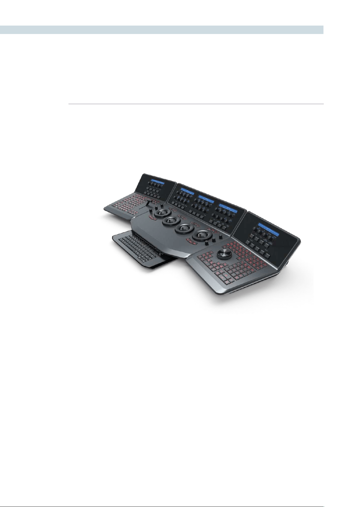
DAVINCI RESOLVE CONTROL SURFACE 404
Trackball Panel
The center panel has the traditional four trackballs, each with a surrounding control ring and no end
stop in either direction. Three variable controls are on each side of the panel, three keys above the
trackballs, three below the left and right most trackballs, and on the LCD panel, three LCD displays,
each with eight variable controls and four keys. The LCD screens are menu-driven and thus the
controls, soft keys, and the display itself depends on the current mode. The menu structure will be
covered later in this User Manual.
The center panel also offers a slide-out keyboard for naming files, as well as for a number of other
operations. The shortcut keys are covered later in this User Manual.
The right most trackball operates similar to a mouse and can also double as an Offset Control. The
other three trackballs are in the traditional DaVinci format (from left to right): Lift, Gamma, and Gain
configuration (Lowlights, Mid-tones, and Highlights).
The far left trackball is Lift control, which provides RGB balance adjustment in the darker range the
image. The next trackball to the right is Gamma control, which provides control over the mid-range
values of the image. The third from the left is the Gain control, which effects the brighter portions of
the image.
The control ring surrounding these trackballs provides amplitude control of the associated Luminance,
Lift, Gamma, or Gain range of the image.
On the left side of the panel are three Luminance knobs. From top to bottom they are Luminance Gain,
Luminance Hue, and Luminance Lift.
DaVinci Resolve Control Surface

CHAPTER
DAVINCI RESOLVE CONTROL SURFACE
DAVINCI RESOLVE CONTROL SURFACE405
19
On the right side there are three more controls, from top to bottom: Saturation, Hue (has the effect of
hue rotation), and Luminance Mix. Above the three left most trackballs you will see these three keys:
RGB: This key resets the RGB balance only to detent.
All: To reset both RGB and level.
Level: If you wish to reset the level while maintaining RGB differential.
Above the right most trackball the three keys are:
Adjust Window: Selection of this key brings up the shape cursors for the current node, and
allows the trackball to position the current window.
Modes: This key allows access to a number of menus and acts as an on/off toggle.
Shift Up Cursor: This shift function changes the cursor views on the main monitor. The user
can select the cursor display including windows on the GUI, but not the
main monitor, or both, as they prefer.
Cursor: The Cursor is used for the Color Picker when in Vector mode. This key also
controls the window display.
Under the left and right most trackballs there are three keys. Operation for the keys under the left-hand
side trackball is not yet implemented.
The keys under the right-hand side trackball provide left, center, and right mouse buttons. The right-
hand side trackball functions as a mouse when the left mouse button is selected, while not in Cursor
mode, and can also double as an Offset Control.

DAVINCI RESOLVE CONTROL SURFACE 406
Reference Configuration
Located at the top left-hand side of the Transport panel are the Deck and Still Select keys. These are
all related to controlling the deck, virtual decks when in multi-playhead mode, and the grabbing and
selection of stills. There is also an Undo and Redo key, a Shift Up and a Save key.
Split (Shift Up In): DaVinci Resolve associates grading information based on source
timecode and as it’s also possible to have source clips with the same
timecode (sorted with file name and/or path, etc), it’s important to
have each source clip identified as a different clip to all the others.
The Split key will split one clip into two on the frame selected. Each
can therefore have their own grade.
In: When marking a transport (virtual or deck) in point you can use the
GUI or this key.
Join (Shift Up Out): JoinisthereverseoftheSplitkey.PlacetheViewerontherstframe
ofaclipandselectJointomergetheprecedingclip.
Out: The Out key is used to select an out point on the transport.
Duration: To define a duration, first select the time using the numerical keypad
(the colon separates the hours, minutes, seconds and frames), and
then select Duration.
Gang: The Gang control permits the user to gang multiple clips so they will
play back from the first frame in synchronization. This is particularly
helpful for checking the impact of a grade on a couple of key shots
when using the PlayHeads feature of DaVinci Resolve.
Undo: The Colorist’s friend. DaVinci Resolve has virtually unlimited undo
steps available.
Redo: If you want to redo a step, use Redo. Ideal when used with undo to
compare two grades quickly.
Source (L): This key selects the source.
Place (Shift Up A ( R )): ): When using playheads this key selects deck R
A ( R )): When using playheads this key selects deck A
F: This key is not implemented
Place (Shift Up B): When using playheads this key selects the location for the
playhead on the UI.
B: When using playheads this key selects deck B
G: This key is not implemented
Place (Shift Up C): When using playheads this key selects the location for the
playhead on the GUI.
C: When using playheads this key selects deck C
H: This key is not implemented
Transport Panel

CHAPTER
DAVINCI RESOLVE CONTROL SURFACE
DAVINCI RESOLVE CONTROL SURFACE407
19
D: When using playheads this key selects deck D
I: This key is not implemented
E: When using playheads this key selects deck E
J: This key is not implemented
Shift Up: Use the Shift Up key as a pre-selector for the keys with an upper
option. Select the keys sequentially and do not hold the Shift Up key
while selecting the second key.
Preroll: The Preroll key us used in conjunction with the numerical keypad to
select a preroll time.
Cue: Selecting Cue will force the transport to the preroll position.
Previous Still: If you have a still selected the Previous Still key will select the
one preceding.
Next Still: The next still is selected if this key is used.
Play Still: When the user selects this key, DaVinci Resolve will automatically
display on the Viewer a wipe between the current scene and the
current still. You can use the fader T-bar to move the wipe position
and in the reference wipe menus change the reference image as
required by moving or resizing. Selecting Play Still a second time will
toggle this mode off.
Save: The most important key on the panel. Besides having an auto-save
feature you can and should consistently save your project with this
key. It only takes a few seconds and can save you hours.
Grab Still: At any time when you are grading selecting the Grab Still key will
automatically grab a full resolution frame from the timeline and
attach the node graph metadata for later display and use.

DAVINCI RESOLVE CONTROL SURFACE 408
Transport Control Keys
Most colorists will use the Transport Control keys every minute of every grade, so they are located for
quickandeasyaccess.Whilenottechnicallywithinthiskeygroup,theJobandShuttleknobisdirectly
above these keys.
Jog: Rotate the jog control to step forward or backward a few frames at
a time.
Shuttle: OntheoutsideoftheJogrotarycontrolistheshuttleknob.This
knob has a detent at the null position and is turned clockwise or
counter-clockwise to shuttle the transport/timeline forward or
reverse at the rate selected by the rotation of the shuttle knob.
Loop: You may wish to repeat a review of a grade of a clip, or a selection
of clips on the timeline; this Loop toggle key selects or deselects the
loop operation.
Render: Once you have finished your grade the Render key selects the
UI screen used for configuration of the render parameters for
your project.
Rec: (Shift Down Render) This key is not yet implemented.
Previous Node: Within the Node Graph on the Color screen you are likely to have a
number of nodes. These are numbered based on the order that you
added them, which may not be the logical image flow order. DaVinci
Resolve Node Graphs are completely user configurable, so you can
add nodes anywhere and in any order you like. Thus, the previous
node key will select the node one lower in numerical order.
Next Node: Similar to the Previous Node key, this selects the node adjacent to
the current node, in this case the next higher numerical position.
Highlight: When in the Vector menus making secondary qualifiers, it’s common
to select the Highlight key to show a high contrast separation of the
qualified color and all other parts of the image. Toggle this key to
turn off. Highlight is used so often it’s also on the fader panel and
when in vectors on the Trackball panel.
Mode: (Shift Down Highlight) Used to toggle the highlight mode from
grey to high contrast.
Shift Down: This is the pre-selection key for functions indicated on the lower
portion of the second keys legend.
First Frame: Selects the first frame of the current clip.
Last Frame: This key selects the last frame of the current clip.
Step Reverse: To step the viewer one frame in reverse along the timeline.
Step Reverse Keyframe: (Shift Down Step Reverse) This key steps backwards one keyframe
on the clip/Track timeline display.
Step Forward: A single frame step forward for each key press.

CHAPTER
DAVINCI RESOLVE CONTROL SURFACE
DAVINCI RESOLVE CONTROL SURFACE409
19
Step Forward Keyframe: (Shift Down Step Forward) For keyframe steps forward on the clip/
Track timeline display.
Previous Scene: Selects the first frame of the previous scene.
Next Scene: Selects the first frame of the next scene.
Rewind: The rewind key places the transport, or timeline in rewind.
Reverse: To play the clip/timeline in reverse select this key.
Stop: You guessed it. This stops the current transport operation.
Forward: The forward key will play the clip/timeline forward.
Fast Forward: The inverse of the Rewind key, fast forward shuttles along the
timeline/transport.

DAVINCI RESOLVE CONTROL SURFACE 410
Memory Access Keys
Forfastanddirectaccesstomemories,theAtoZMemories,orMems,usethissectionoftheTransport
panel. This is an extremely powerful feature. With any clip selected on the timeline, with a single key
press, for example “A,” the grading parameters stored in memory A, including the node structure, sizing,
etc. will be automatically applied to the current clip.
O (Shift Up A): Selects memory O
A: Selects memory A
I (Shift Down A): Selects Memory I
R (Shift Up B): Selects memory R
B: Selects memory B
J (Shift Down B): SelectsMemoryJ
And so forth
All (Shift Up Base Mem): This function will return all grades for all nodes on the clip
to the default grade/settings and clears dynamic marks.
Note:Thereisanexceptiontotherule.Ifa‘PresetSize’has
been set for the clip the Base Mem sizing will default to this
preset size.
Base Mem: The Base Mem key clears the current node of all its grades
and marks. Again, with the preset exception noted above.
Reset (Shift Down Base Mem Crnt): This key deletes all nodes in the clip with the exception of
the first node and resets the grades to default and clears
the marks.
Preview Mem: To preview one of the memory grades on any clip, select the
clip on the timeline, select Preview Memory and then the
memory. This key is a toggle so if you do not like the grade
on the memory for that clip, select Preview Mem again and
the clips grade will revert to the original.
Original Mem: Each clip by default has a memory of its grade, sizing, etc.
The metadata for every clip is saved in reference to the
source timecode. If you are grading a clip and move from it
to another clip, the grade is saved automatically in a memory
for that clip. If you come back to the clip and make a change
to the grade, then decide you don’t like the change, select
Original Mem to return to the grade status you found when
returning to the clip.
Scroll: The Scroll key selects a soft menu on the Trackball panel so
clips or frames can be scrolled via the rotary control in the
soft menu.

CHAPTER
DAVINCI RESOLVE CONTROL SURFACE
DAVINCI RESOLVE CONTROL SURFACE411
19
Numerical Entry Key Group
On the center right-hand side of the Transport panel is the Numerical Entry key group. Here you will
find numbers 0 to 9 and associated keys for entering timecode and clip numbers. You will notice the
numbers you type are displayed in a scratchpad area to the right of the menu bar on the bottom of
the GUI.
Current: To store a new grade in any memory, first select the
Current key and then the memory of your choice.
All Color PTZR: This key is a toggle that selects the parameters that will be
copied when updating a grade. Generally, all aspects of the
gradearecopied,includingPTRZ,butonoccasionyoumay
wish to copy only the grade and not the sizing parameters.
InthiscaseusetheCopyModetoselectgrade/noPTRZ
orgradewithPTRZ.Youcanseethecliptimelinetoggle
betweenthenodeselectedandtheinputPTRZparameters.
Select Node: Use this key in conjunction with the numerical keys to
select any node on the current Node Graph. First select the
nodenumber,andthen‘SelectNode.’Thecurrentnodewill
change to the selected node.
Backspace: The backspace key moves you one item left in the numerical
scratch pad display. This permits correction of your
numerical entries.
0 to 9: You guessed it. These are the numbers!
, (Comma): The comma is used just prior to the frame count if you wish
to indicate a drop frame timecode.
: (Colon): When typing in timecode, the convention is to type the
hours followed by a colon, then the minutes, a colon, the
seconds, a colon, and finally the frames. DaVinci Resolve
does not need to have leading numbers entered where they
offer no value and the default value is 0, so to type one hour,
three minutes, zero seconds and sixteen frames, you do not
need to type 01:03:00:16. Simply type 1:3::16 and then press
’Enter.’ This speeds timecode entry.
Clear: Will clear the scratchpad number.
- (Minus): Select the minus key prior to the number to reduce
the number.
+ (Plus): The Plus key selected prior to a number adds the number.
Take/Enter: To accept or enter any input select this Take/Enter key.

DAVINCI RESOLVE CONTROL SURFACE 412
List Marking
The List Marking keys are on the bottom right hand side of the Transport panel. The functions are
replicated on the Fader Bar panel. The List Marking group of keys is used in association with the timeline
and controls the selection of keyframe points for the start and end of dynamic transitions of the grade,
called Dynamics.
Delete: This key deletes the Dynamic.
Start Dynamic: This key is used to select the first keyframe in a transition, a Dynamic.
The transition may be a grade change, a sizing, the addition of a matte,
or any number of 100 variables all of which are associated with the
Node Graph and the clip or Track timeline.
Trim: This key is used with the numerical keypad to trim a mark position.
Ripple Value: If you have a grade, or effect, or just an adjustment and you would like
to ripple this effect over another or a large number of other clips, use
Ripple Value.
Mark: Like the Start Dynamic key, Mark is a major key. It places a keyframe on
the clip timeline and between the Start Dynamic and Mark, or between
multiple Marks you can change the grade.
Scene (Shift Down Mark): To quickly switch to the Scene Cut Detection screen select Shift
Down then Mark.
Lift Mark: Often you may place a mark in the wrong spot so place your cursor
on the mark and use Lift Mark to remove it.
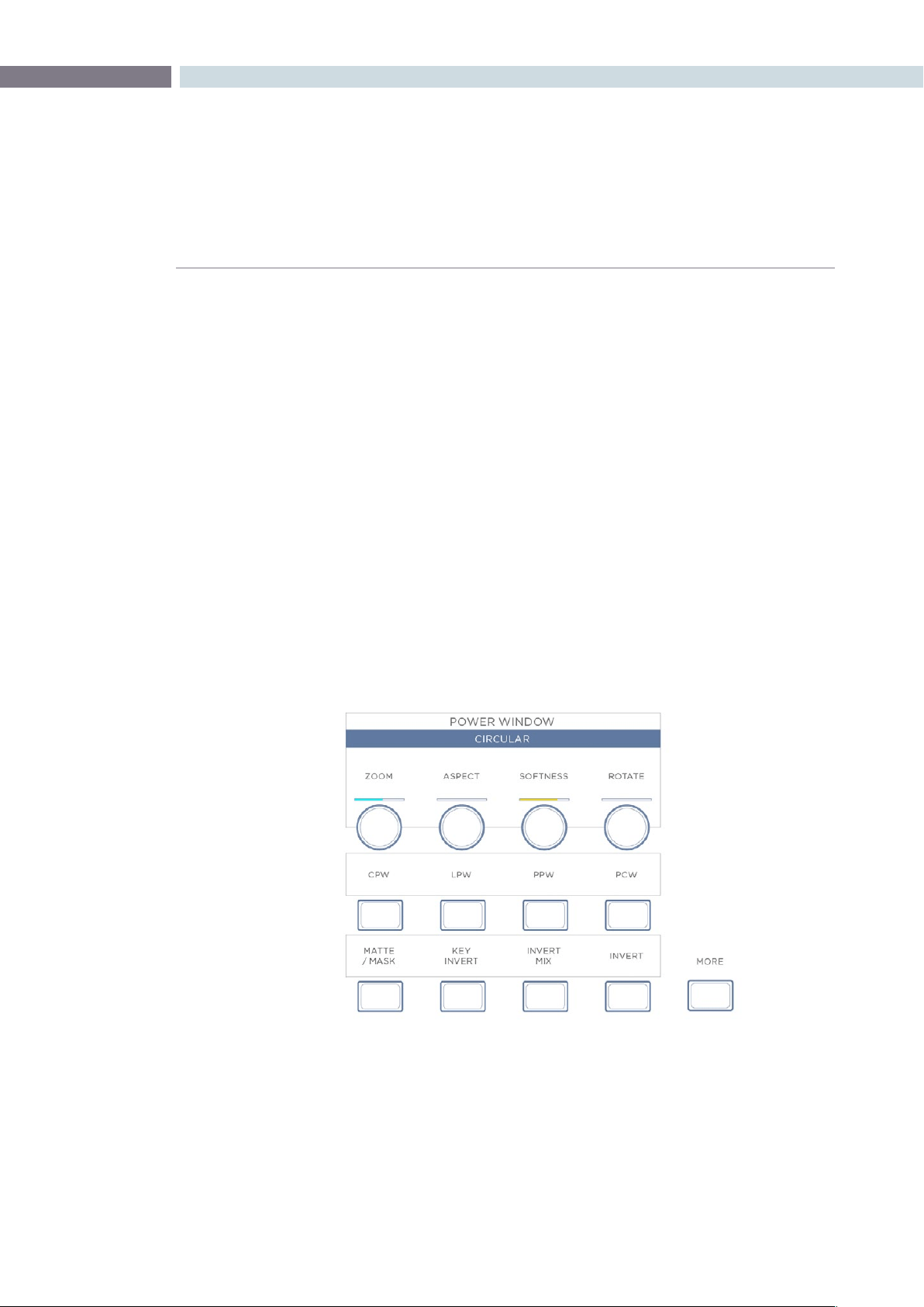
CHAPTER
DAVINCI RESOLVE CONTROL SURFACE
DAVINCI RESOLVE CONTROL SURFACE413
19
Menus, Soft Keys and Soft Pot Controls
All three panels have liquid crystal displays (LCDs) and within this display, a selection of soft keys and
soft pots for variable control of different parameters. The functionality of these keys and pots is based
on the menus displayed on the LCD and changes dynamically with the operation of DaVinci Resolve.
The soft menu structure is designed to offer simultaneous control over multiple functions and a fast,
logical and efficient way to move between the menus. Each of the menus with the applicable control
functions is described below.
The LCD has a two-line title description of the menus main function and there are two lines of text above
each pot or switch describing the control. The Fader and Transport panels can have quite independent
controls compared to the Trackball panel. For example, the Fader panels default menu is for Windows
adjustment while the default menu for the Transport panel is Sizing. This allows users to control windows
or sizing full time, regardless of Trackball Panel mode and eliminates the need to change the work
surface to adjust window position or input sizing.
Soft Key and Soft Pot Control Conventions
Below is a typical soft menu from the Fader panel. The title bar shows the menu mode, in this case
Circular Power Window. The top row of legends refers to the soft pots beneath it, in this case the
windowposition(PanandTilt),ZoomandSoftnesscontrols.A“more”keytotherightofthesecontrols
(not shown) allows you to access a second level of soft pots for Aspect and Rotation. Both side panels
have a ’More’ key, which provides another layer of menus, if applicable.
The second row of legends refers to the soft keys beneath them, which in this case select the desired
window for adjustment. The bottom row of legends refers to the bottom row of soft keys, which control
the state of the window and allow you to enable the windows as desired. The controls are always
located very close to the label, so there are no parallax errors and learning the panel is an easy task.
Stereoscopic Viewer Right Click Options

DAVINCI RESOLVE CONTROL SURFACE 414
In this mode, the Fader panel soft menus are used for window control. When windows are selected on
the Trackball panel, these menus do not change. This allows the user, for example, to select PowerCurve
windows on the Trackball panel and adjust its parameters simultaneously with a Circular PowerWindows
on the Fader panel.
The Transport panel soft menus are used to control input or output sizing, which provides a way to set
sizing without changing the main work surface. These menus can also be used simultaneously with
sizing menus on the Trackball panel, offering a full suite of controls at your fingertips.
Soft menus use full-color LCDs that allow users to set the brightness and color of the displays to suit
their taste and working environment. The panels offer feedback to let you know at a glance the relative
settings of these controls, and also highlight the last control touched. For example, if a control is out of
Base Mem, the panels show this with a selectable color highlight.
In the image shown above, Aspect and Rotate are in Base Mem, while Softness is the last control
touched,signiedbytheyellowsettingindicator,andZoomisnotatBaseMem,signiedbythecyan
color of the setting indicator.
The panel LCD and key brightness and color settings are adjusted in the Resolve Configuration screen
on the Panel Tab.
Menu Layouts
The DaVinci Resolve Control surface has a number of menus and many are selectable via different
paths to match the operational workflow of colorists. Selection of a key on one panel may update the
menu and soft keys and soft pots on one or more panels.
Often the update is to a section of the panel display so you can quickly switch back and forward to
different modes as you grade. The menus are shown here identified by their core functionality.
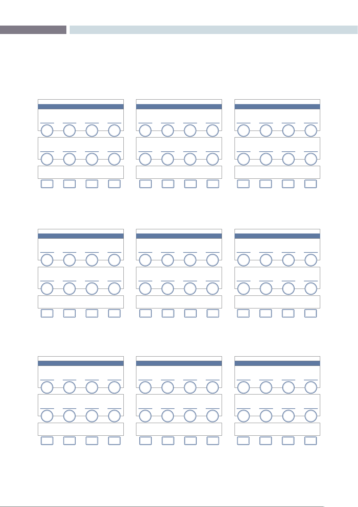
CHAPTER
DAVINCI RESOLVE CONTROL SURFACE
DAVINCI RESOLVE CONTROL SURFACE415
19
PRIMARY
PRIMARY
CHANNEL OFFSET / CUSTOM CURVES
PRIMARY
YSFX
VECTOR QUALIFIERS
HSL PARAMETERS / QUALIFIER BLUR
MASTER
OFFSET
LUM
YSFX
HUE
SHIFT
RED
OFFSET
RED
YSFX
SAT
GAIN
GREEN
OFFSET
GREEN
YSFX
LUM
LIFT
BLUE
OFFSET
BLUE
YSFX
LUM
GAIN
LUM
CURVE
RED
CURVE
GREEN
CURVE
BLUR
BLUE
CURVE
OFFSET
NODES CLIPSSIZING
CURVE
MONITOR
PRIMARIES
TRACK-
BALL
OFFSET
KEY
MODE
VECTORS POTS
PRINTER
LIGHTS
PRIMARY / POTS
PRIMARIES
LUM / GREEN POTS
PRIMARIES
RED / BLUE POTS
PRIMARIES
HSL PARAMETERS / QUALIFIER BLUR
MASTER
OFFSET
RED
OFFSET
HUE
SHIFT
LUM
BLACK
RED
BLACK
SAT
GAIN
LUM
GAMMA
RED
GAMMA
LUM
LIFT
LUM
GAIN
RED
GAIN
LUM
GAIN
GREEN
OFFSET
BLUE
OFFSET
GREEN
BLACK
BLUE
BLACK
GREEN
GAMMA
GLUE
GAMMA
BLUR
GREEN
GAIN
BLUE
GAIN
OFFSET
NODES CLIPSSIZING
CURVE
MONITOR
PRIMARIES
KEY
MODE
VECTORS MAIN
PRINTER
LIGHTS
PRIMARY / CLIPS
PRIMARIES
SCENE WHITE CLIPS
PRIMARIES
SCENE BLACK CLIPS
PRIMARIES
HSL PARAMETERS / QUALIFIER BLUR
MASTER
CLIP
MASTER
CLIP
HUE
SHIFT
RED
CLIP
RED
CLIP
SAT
GAIN
GREEN
CLIP
GREEN
CLIP
LUM
LIFT
BLUE
CLIP
BLUE
CLIP
LUM
GAIN
MASTER
SOFT
MASTER
SOFT
RED
SOFT
RED
SOFT
GREEN
SOFT
GREEN
SOFT
BLUR
BLUE
SOFT
BLUE
SOFT
OFFSET
NODES CLIPSSIZING
CURVE
MONITOR
PRIMARIES
TRACK-
BALL
KEY
MODE
VECTORS POTS
PRINTER
LIGHTS
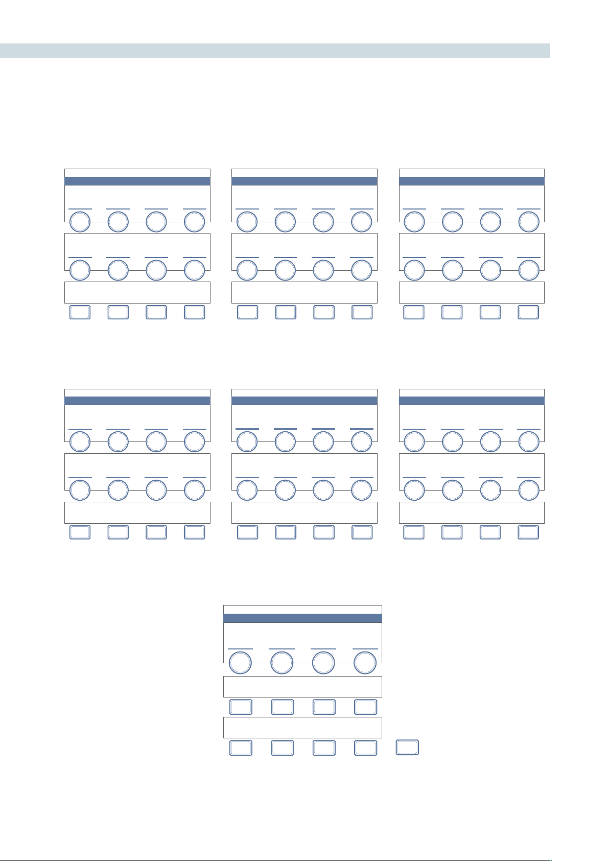
DAVINCI RESOLVE CONTROL SURFACE 416
PRIMARY / KEY MODE
PRIMARIES
CHANNEL OFFSET / CUSTOM CURVES
KEY PROCESSING
KEY PARAMETERS
PRIMARIES
HSL PARAMETERS / QUALIFIER BLUR
MASTER
OFFSET
HUE
SHIFT
RED
OFFSET
POST MIX
GAIN
SAT
GAIN
GREEN
OFFSET
POST MIX
OFFSET
LUM
LIFT
BLUE
OFFSET
LUM
GAIN
LUM
CURVE
QUALIFIER
GAIN
RED
CURVE
QUALIFIER
OFFSET
GREEN
CURVE
EXT KEY
GAIN
BLUR
BLUE
CURVE
EXT KEY
OFFSET
OFFSET
NODES
MAT TE
/ MASK
POST MIX
INVERT
SIZING INVERTPRIMARIES
MAT TE
/ MASK
VECTORS INVERT
PRINTER
LIGHTS
PRIMARY / KEY MODE
EXTERNAL MATTE SIZING
PAN TI LT ZOOM ROTATE
X - SIZE Y - SIZE
NODES H - FLIPSIZING V - FLIPPRIMARIES VECTORS LOCK
OUTPUT SIZING
STANDARD PRESETS
MASTER + RED + GREEN + BLUE +
MASTER - RED - GREEN - BLUE -
MORE
PRIMARY / PRINTER LIGHTS
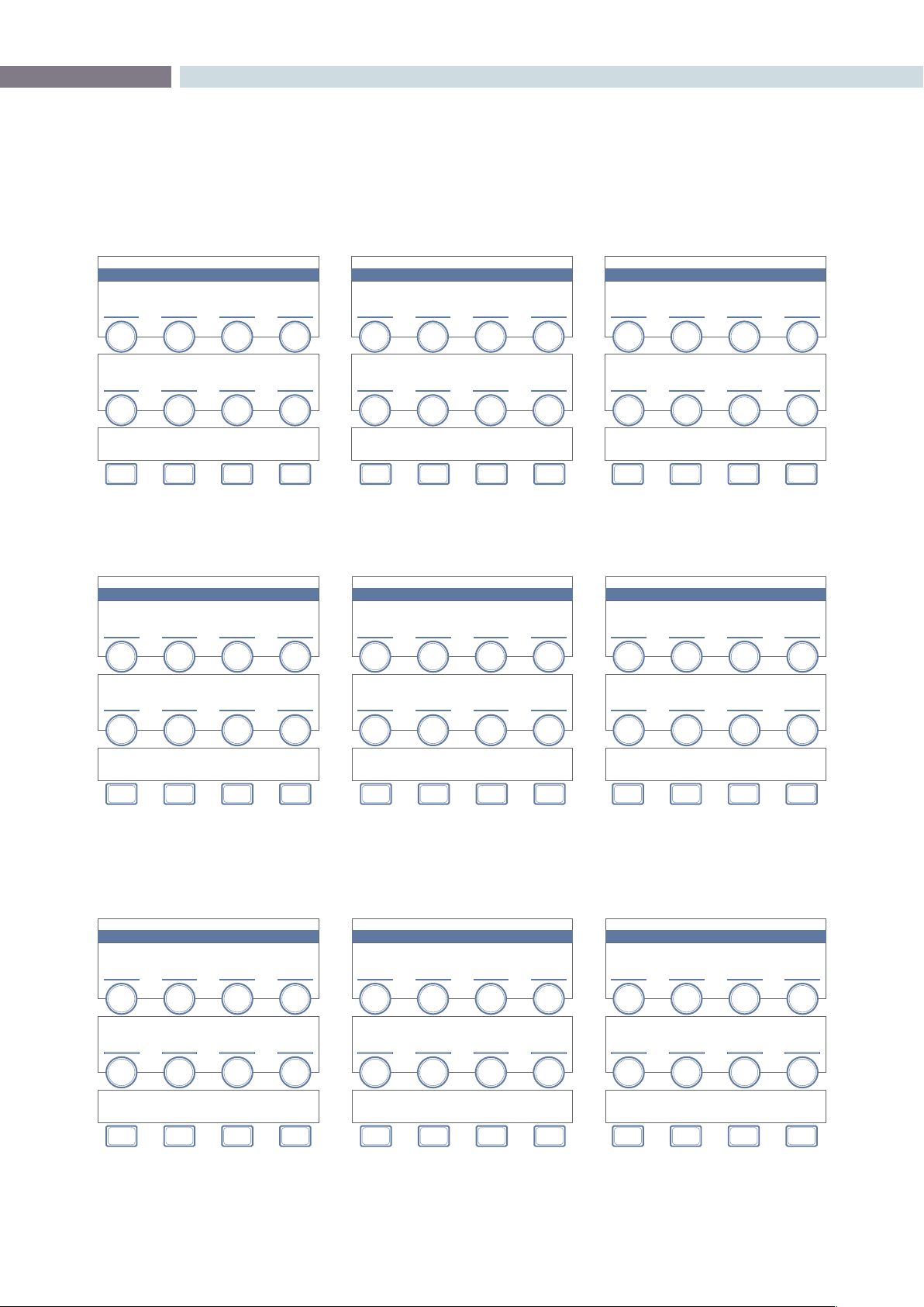
CHAPTER
DAVINCI RESOLVE CONTROL SURFACE
DAVINCI RESOLVE CONTROL SURFACE417
19
VECTORS / IMAGE MODE OR QUALIFIER MODE
IMAGE BLUR
GAUSSIAN IMAGE BLUR
VECTOR QUALIFIER
KILOVECTOR HSL QUALIFIERS
VECTORS QUALIFIER
KILOVECTOR HSL QUALIFIERS
IMAGE
BLUR
HUE
CENTRE
LUM
LOW CLIP
H / V
RAT IO
HUE
WIDTH
LUM
LOW SOFT
HUE
SOFTNESS
LUM
HI SOFT
QUALIFIER
BLUR
HUE
SYMMETRY
LUM
HI CLIP
SAT
LOW CLIP
S & G
OFFSET
SAT
LOW SOFT
S & G
RADIUS
SAT
HI SOFT
QUALIFIER
BLUR
SAT
HI CLIP
H / V
OFFSET
NODES PRESETS
QUALIFIER
MODE
SIZING
COLOR
PICKER
HIGH
LIGHT
PRIMARIES
IMAGE
MODE
INVERTVECTORS
MASTER
/ COLOR
KEY
MODE
VECTORS / IMAGE MODE OR QUALIFIER MODE
IMAGE BLUR
COLOR IMAGE BLUR
VECTOR QUALIFIER
KILOVECTOR HSL QUALIFIERS
VECTORS QUALIFIER
KILOVECTOR HSL QUALIFIERS
RED
BLUR
HUE
CENTRE
LUM
LOW CLIP
GREEN
BLUR
HUE
WIDTH
LUM
LOW SOFT
BLUE
BLUR
HUE
SOFTNESS
LUM
HI SOFT
HUE
SYMMETRY
LUM
HI CLIP
RED
H/ V R ATIO
SAT
LOW CLIP
S & G
OFFSET
GREEN
H/ V R ATIO
SAT
LOW SOFT
S & G
RADIUS
BLUE
H/V
RAT IO
SAT
HI SOFT
QUALIFIER
BLUR
SAT
HI CLIP
H / V
OFFSET
NODES
SIX
VECTOR
QUALIFIER
MODE
SIZING
COLOR
PICKER
HIGH
LIGHT
PRIMARIES
IMAGE
MODE
INVERTVECTORS
MASTER
/ COLOR
KEY
MODE
VECTORS / IMAGE MODE OR QUALIFIER MODE
IMAGE SHARPENING
IMAGE SHARPENING CORING
VECTOR QUALIFIER
KILOVECTOR HSL QUALIFIERS
VECTORS QUALIFIER
KILOVECTOR HSL QUALIFIERS
SHARP
AMOUNT
HUE
CENTRE
LUM
LOW CLIP
HUE
WIDTH
LUM
LOW SOFT
SCALING
HUE
SOFTNESS
LUM
HI SOFT
SOFTNESS
HUE
SYMMETRY
LUM
HI CLIP
SAT
LOW CLIP
S & G
OFFSET
SAT
LOW SOFT
S & G
RADIUS
SAT
HI SOFT
QUALIFIER
BLUR
LEVEL
SAT
HI CLIP
H / V
OFFSET
NODES
SIX
VECTOR
QUALIFIER
MODE
SIZING
COLOR
PICKER
HIGH
LIGHT
PRIMARIES
IMAGE
MODE
INVERTVECTORS
MASTER
/ COLOR
KEY
MODE
DAVINCI RESOLVE CONTROL SURFACE 418
VECTORS / IMAGE MODE OR QUALIFIER MODE
IMAGE SHARPENING
IMAGE SHARPENING CORING
VECTOR QUALIFIER
KILOVECTOR HSL QUALIFIERS
VECTORS QUALIFIER
KILOVECTOR HSL QUALIFIERS
RED
SHARPEN
HUE
CENTRE
LUM
LOW CLIP
GREEN
SHARPEN
HUE
WIDTH
LUM
LOW SOFT
BLUE
SHARPEN
HUE
SOFTNESS
LUM
HI SOFT
SOFTNESS
HUE
SYMMETRY
LUM
HI CLIP
RED
RAT IO
SAT
LOW CLIP
S & G
OFFSET
GREEN
RAT IO
SAT
LOW SOFT
S & G
RADIUS
BLUE
RAT IO
SAT
HI SOFT
QUALIFIER
BLUR
LEVEL
SAT
HI CLIP
H / V
OFFSET
NODES
SIX
VECTOR
QUALIFIER
MODE
SIZING
COLOR
PICKER
HIGH
LIGHT
PRIMARIES
IMAGE
MODE
INVERTVECTORS
MASTER
/ COLOR
KEY
MODE
VECTORS / IMAGE MODE OR QUALIFIER MODE
MIST EFFECT
MASTER MIST
VECTOR QUALIFIER
KILOVECTOR HSL QUALIFIERS
VECTORS QUALIFIER
KILOVECTOR HSL QUALIFIERS
MASTER
HUE
CENTRE
LUM
LOW CLIP
H / V
RAT IO
HUE
WIDTH
LUM
LOW SOFT
SCALING
HUE
SOFTNESS
LUM
HI SOFT
MIX
HUE
SYMMETRY
LUM
HI CLIP
SAT
LOW CLIP
S & G
OFFSET
SAT
LOW SOFT
S & G
RADIUS
SAT
HI SOFT
QUALIFIER
BLUR
SAT
HI CLIP
H / V
OFFSET
NODES
SIX
VECTOR
QUALIFIER
MODE
SIZING
COLOR
PICKER
HIGH
LIGHT
PRIMARIES
IMAGE
MODE
INVERTVECTORS
MASTER
/ COLOR
KEY
MODE
VECTORS / IMAGE MODE OR QUALIFIER MODE
MIST EFFECT
COLOR MIST
VECTOR QUALIFIER
KILOVECTOR HSL QUALIFIERS
VECTORS QUALIFIER
KILOVECTOR HSL QUALIFIERS
RADIUS
HUE
CENTRE
LUM
LOW CLIP
H / V
RAT IO
HUE
WIDTH
LUM
LOW SOFT
SCALING
HUE
SOFTNESS
LUM
HI SOFT
MIX
HUE
SYMMETRY
LUM
HI CLIP
RED
RADIUS
SAT
LOW CLIP
S & G
OFFSET
GREEN
RADIUS
SAT
LOW SOFT
S & G
RADIUS
BLUE
RADIUS
SAT
HI SOFT
QUALIFIER
BLUR
MIST
PARAM-
ETER
SAT
HI CLIP
H / V
OFFSET
NODES
SIX
VECTOR
QUALIFIER
MODE
SIZING
COLOR
PICKER
HIGH
LIGHT
PRIMARIES
IMAGE
MODE
INVERTVECTORS
MASTER
/ COLOR
KEY
MODE
CHAPTER
DAVINCI RESOLVE CONTROL SURFACE
DAVINCI RESOLVE CONTROL SURFACE419
19
VECTORS / IMAGE MODE OR QUALIFIER MODE
IMAGE SHARPENING
IMAGE SHARPENING CORING
VECTOR QUALIFIER
KILOVECTOR HSL QUALIFIERS
VECTORS QUALIFIER
KILOVECTOR HSL QUALIFIERS
SHARP
AMOUNT
RED
LOW CLIP
BLUE
LOW CLIP
RED
LOW SOFT
BLUE
LOW SOFT
RED
HI SOFT
BLUE
HI SOFT
SOFTNESS
RED
HI CLIP
BLUE
HI CLIP
GREEN
LOW CLIP
S & G
OFFSET
GREEN
LOW SOFT
S & G
RADIUS
GREEN
HI SOFT
QUALIFIER
BLUR
LEVEL
GREEN
HI CLIP
H / V
OFFSET
NODES
SIX
VECTOR
QUALIFIER
MODE
SIZING
COLOR
PICKER
HIGH
LIGHT
PRIMARIES
IMAGE
MODE
INVERTVECTORS
MASTER
/ COLOR
KEY
MODE
VECTORS / IMAGE MODE OR QUALIFIER MODE
IMAGE SHARPENING
IMAGE SHARPENING CORING
VECTOR QUALIFIER
KILOVECTOR HSL QUALIFIERS
VECTORS QUALIFIER
KILOVECTOR HSL QUALIFIERS
SHARP
AMOUNT
SOFTNESS
LUM
LOW CLIP
S & G
OFFSET
LUM
LOW SOFT
S & G
RADIUS
LUM
HI SOFT
QUALIFIER
BLUR
LEVEL
LUM
HI CLIP
H / V
OFFSET
NODES
SIX
VECTOR
QUALIFIER
MODE
SIZING
COLOR
PICKER
HIGH
LIGHT
PRIMARIES
IMAGE
MODE
INVERTVECTORS
MASTER
/ COLOR
KEY
MODE
VECTORS / PRESET
HIGH
LUM
BACK RED
LOW
LUM
MAGENTA
HIGH & LOW
LUM
GREEN
BLUEYELLOW CYA N
DAVINCI RESOLVE CONTROL SURFACE 420
SIZING
REFERENCE WIPE SIZING
INPUT SIZING
PAN PANTILT T ILTZOOM ZOOMROTATE ROTATE
INPUT
PRESET
H
SIZE
H
SIZE
V
SIZE
V
SIZE
NODES OUTPUT
SOURCE
BLANKING
SIZING
REF ADJUST
ENABLE
MODIFY
PAR
PRIMARIES
REF ADJUST
H - FLIP
H
FLIP
VECTORS
REF ADJUST
V - FLIP
V
FLIP
SIZING / OUTPUT
OUTPUT BLANKING
OUTPUT SIZING
LEFT PANRIGHT TILTTOP ZOOMBOTTOM ROTAT E
H
SIZE
V
SIZE
NODES INPUT
USE
DE FAU LT
SIZING
OUTPUT
PRESET
ASPECT
MATCH
PRIMARIES
H
FLIP
BLANKINGVECTORS
V
FLIP
PVW
MODE
HSL
+
HSL
-
SOFTNESS
+
SOFTNESS
-
VECTOR / COLOR PICKER
CHAPTER
DAVINCI RESOLVE CONTROL SURFACE
DAVINCI RESOLVE CONTROL SURFACE421
19
WINDOWS / CPW
PRIMARIES
CHANNEL OFFSET / CUSTOM CURVES
POWER WINDOW
CIRCULAR
PRIMARIES
HSL PARAMETERS / QUALIFIER BLUR
MASTER
OFFSET
ZOOM
HUE
SHIFT
RED
OFFSET
ASPECT
SAT
GAIN
GREEN
OFFSET
SOFTNESS
LUM
LIFT
BLUE
OFFSET
ROTATE
LUM
GAIN
LUM
CURVE
PAN
RED
CURVE
TILT
GREEN
CURVE
QUALIFIER
BLUR
BLUE
CURVE
H / V
OFFSET
NODES CPW CLIPSSIZING LPW
CURVE
MONITOR
PRIMARIES
PPW
KEY
MODE
VECTORS PCW
PRINTER
LIGHTS
OUTPUT SIZING
STANDARD PRESETS
1.33 1.66 1.78 1.85
2.35 USER
MORE
SIZING / OUTPUT / BLANKING
OUTPUT SIZING
USER PRESETS
USER 1 USER 2 USER 3 USER 4
USER 5 SAVE BACK
MORE
SIZING / OUTPUT / BLANKING
DAVINCI RESOLVE CONTROL SURFACE 422
WINDOWS / LPW
PRIMARIES
CHANNEL OFFSET / CUSTOM CURVES
POWER WINDOW
LINEAR
PRIMARIES
HSL PARAMETERS / QUALIFIER BLUR
MASTER
OFFSET
ZOOM
HUE
SHIFT
RED
OFFSET
SAT
GAIN
GREEN
OFFSET
SOFTNESS
LUM
LIFT
BLUE
OFFSET
ROTATE
LUM
GAIN
LUM
CURVE
PAN
RED
CURVE
TILT
GREEN
CURVE
QUALIFIER
BLUR
BLUE
CURVE
RESET
H / V
OFFSET
NODES CPW CLIPSSIZING LPW
CURVE
MONITOR
PRIMARIES
PPW
KEY
MODE
VECTORS PCW
PRINTER
LIGHTS
POWER WINDOW
CIRCULAR
ZOOM ASPECT SOFTNESS ROTATE
CPW LPW PPW PCW
MAT TE
/ MASK
KEY
INVERT
INVERT
MIX
INVERT
MORE
POWER WINDOW
CIRCULAR
PAN TILT SOFTNESS ROTATE
CPW LPW PPW PCW
MAT TE
/ MASK
KEY
INVERT
INVERT
MIX
INVERT
MORE


20
Glossary

CHAPTER
GLOSSARY
GLOSSARY425
20
Glossary
10-Bit: The identification for 1023 levels within the digital signal.
24p: This is a 24 frame progressive format.
16 X 9: This is a term that describes a wide screen television
format that has the measurements of 16 X 9.
2K: A color correction system developed by DaVinci Systems.
It is also a data file with the resolution of 2048 X 1556.
2K Plus: A color correction system developed by DaVinci Systems.
4K: An abbreviation for a data file with the resolution of 4096
X 3112.
4:2:2: This refers to a digital signal with half chrominance
resolution and full luminance resolution.
4:4:4: This refers to a digital signal with full levels of luminance
and chrominance information.
A
Access Time: This term refers to the amount of time that is needed to
load information from a data storage device.
ACE: This is an abbreviation for the American Cinema Editors.
Anamorphic: A term which refers to a squeezed or anamorphic image
which is either unsqueezed with a lens during projection
or by using a special video monitor. In regards to motion
picture applications, the term is generally applied to wide-
screen formats such as CinemaScope, Panavision or
SuperScope.
Archive: This generally refers to the storage of information. This can
apply to either film or data storage.
ASA: A measurement of film sensitivity developed by the
American National Standards Institution.
ASC: An abbreviation which is short for the American Society of
Cinematographers.
Assemble Edit: This refers to a video edit which picks up after the
completion of previously recorded material on the tape.
Aspect Ratio: A term that refers to the height to width of an image.
ATSC: An abbreviation for the Advanced Television Systems
Committee.
B
Background Processing: A term that is applied to a computer operation which is
performed at the same time when another operation is
being carried out.

GLOSSARY 426
Best Light: This generally refers to a color correction which is not quite
a scene-by-scene color correction and not a one-light color
correction. It’s generally a correction which is designed to
be finished later in a tape-to-tape correction.
Bit: A name which is applied to one fragment of digital data.
Buffer: This term refers to data storage within RAM.
Byte: A name which pertains to a group of eight memory bits.
C
CinemaScope: A trademarked name for an anamorphic wide screen
process originally developed in France by Professor Henri
Chretien. The rights to the format were later purchased by
20th Century Fox Film Corporation in 1952. The basis for
the process involved shooting material with special optics
that recorded a squeezed or anamorphic image on the film.
When the image was projected, another lens was applied
to the projector which un-squeezed the material and
displayed a wide screen image.
Cineon: A term which is generally applied to a data file with a “.cin”
extension. It is a 10-bit log file.
Clapperboard: A term which is applied to a board which is shown at the
beginning of each uncut film scene. It is used for the purpose
of identification and manual sound synchronization.
Clip: A term which is applied to a single file or scene within a
non-linear timeline.
Clipped Whites: A term which is associated with a luminance correction
that is so high that the detail is cut off or clipped.
Color Balance: The overall adjustment of the scene’s color information.
Clipping: Refers to a method of retaining levels within legal limits.
Color Bars: A test signal made up of eight color bars which is recorded
on a tape to ensure the levels remain consistent when
played on other equipment.
Color Depth: A term which pertains to the image’s range of color.
Color Correction: The process of adjusting an image’s color balance
Color Correction Computer: A device used for adjusting and storing color corrections.
Color Grading: This generally refers to the process of balancing the
image’s color balance.

CHAPTER
GLOSSARY
GLOSSARY427
20
Color Temperature: A term which refers to the measurement of a light’s
color. Warmer colored lights measure out to a lower color
temperature, while bluer illumination measures out to a
higher color temperature. The measurement is carried out
on a scale known as Kelvin.
Color Timing: A name which is applied to the balancing of image and
color in motion picture laboratories by a color timer.
Crushed Blacks: When the image is balanced so that the black or lift control
causes the detail within the black information to be lost,
this is referred to as crushed.
Conform: The method of assembling scenes or clips in an order
defined by an Edit Decision List.
Compression: A term which is applied to the reduction in file size by the
removal of un-needed information.
CPU: This is an abbreviation for Central Processing Unit.
CRT: A term which is short for Cathode Ray Tube.
D
Daily: A name which is applied to a positive film print which has
been made in order to see the results of the day’s shoot.
Data: A term which is applied to computer or digital information.
DDR: A name which is applied to a Digital Disk Recorder.
Default Setting: A term which is applied to a setting which has been pre-
defined by the manufacturer.
Densitometer: The name of a measuring device that shows the object’s
amount of transmitted light.
DIN: A term which is short for Deutsche Industrie Norm. It is
used for measurement of film speeds.
DP: A term which is short for Director of Photography.
DPX: A file format which is short for Digital Moving Picture
Exchange and developed by the SMPTE. The file has the
extension of “.dpx” It is similar to the Cineon file format
except that it can be either a log or linear.
Drag and Drop: A term which is applied to the method of moving
information within an application by using the mouse to
drag it to the desired location and letting go of the mouse
button which drops it into the area.

GLOSSARY 428
E
EBU: A term which is short for European Broadcasting Union.
EBU Color Bars: A color bar signal which was created by the European
Broadcasting Union.
EBU Time Code: A 25 frame per second time code standard which was
created by the European Broadcasting Union.
Edit Decision List: This is a list of in and out points which has been created
by an editing system; it is also known as an EDL.
EDL: This an abbreviation for Edit Decision List
EIA: An abbreviation for television and audio standards listing
association, Electronic Industries Association.
EIA Color Bars: A seven color bar test chart which was created by
Electronic Industries Association.
F
FCC: An abbreviation for the Federal Communications
Commission.
Field: Within an interlaced signal, a video frame is comprised of
two fields. One field contains even numbered lines, while
the other contains odd numbered lines.
File Extension: A term which refers to the last part of a data file such as
.cin or .dpx.
Film Recorder: A device which is used to recording image data files back
to film.
Film Scanner: A device to transferring film to data formats in high
resolution.
Fps: A term which refers to Frames per Second.
Frame Grab: A term which generally applied to storing a frame
for comparison.
G
Gain: A term which is applied to the luminance information
within an image.
Gigabyte: A type of measurement which is one thousand
million bytes.
Gauge: A term which is applied to the width of a film stock.
Global: A correction which is applied to a series of clips or events.
Grains: The individual grains within the structure of a film stock.

CHAPTER
GLOSSARY
GLOSSARY429
20
GSN: This term is short for Gigabyte System Network and is a
high speed network standard.
GUI: A term which is short for Graphic User Interface.
H
Handles: A term which is applied to additional material which
is required beginning and end of each clip. It is usually
required when effects such as dissolves are to be added.
HDTV: A general term which applies to High Definition Television.
Head: This refers to the beginning of a roll of film.
Histogram: A display which shows the dynamic range and contrast of
an image. The X axis within the display shows the luminance
of the pixel, while the Y axis displays the amount of pixels.
HSDL: A term which short for High Speed Data Link.
I
Illegal Video: A term which is applied to signal levels which do not fall
within a broadcast standard range.
Import: The process of importing data into an application.
Insert Edit: An editing mode which records audio and/or video onto a
pre-striped videotape.
Interlace: A term which is applied to when the image contains two
fields, one with lines which are even numbered and the
other with lines which odd numbered.
Internegative: A negative which is produced in a laboratory and made
from an Interpositive for the expressed purpose of
eventually making release prints.
Interpositive: A positive image on a negative like film stock which is
made directly from the original negative for the expressed
purpose of creating an Internegative.
IRE: This refers to a unit of measurement developed by the
Institute of Radio Engineers.
ISO: A term which is applied to an Isolation Reel. It is also
an abbreviation for the International Organization for
Standardization.
ITU-R 601: This is standard definition component digital
video standard created by the International
Telecommunications Union.

GLOSSARY 430
J
JPEGCompression:Thisreferstoalossycompressionalgorithmmethod.
JPEGisanabbreviationforJointPhotographic
Experts Group.
K
Kelvin: The name for a scale that measures the color of a
light source.
Key frames: A term which generally refers to events or marks within a
clip or scene.
L
Leader: A section of film at the beginning of a film roll. Leader can
be in the form of blank film, a countdown or even a clock.
Letterbox: The method of displaying the entire contents of a wide
screen image on a television monitor. This will show the
entire image within the center of the display and there will
be black borders on the top and bottom.
Lossless compression: A method of file compression which performs the
function without loosing any information.
Lossy Compression: A type of data compression that discards information in
order to complete the function.
Lousy Compression: Unwanted compression.
LTC: An abbreviation for Longitudinal Time Code.
LUT: Otherwise known as a Lookup Table. It is essentially a
conversion table. It can be used to perform a conversion
between color spaces.
M
Macro: A button or key which is programmed to carry out a task
which was normally done by pressing a series of buttons
Mask: A method of masking or isolating a region within an image
by using a source such as a Power Window.
Matte: A signal which cuts a section of the image for the purpose
of replacement with other information.
Moiré: An effect which is caused by lines within the material that
conflict with the scan lines.
Monochrome: Another term for black & white film stock.

CHAPTER
GLOSSARY
GLOSSARY431
20
MOS: An abbreviation for “mit out sound”, meaning “with
out sound”.
MPEG: This is an abbreviation for Moving Picture Experts Group
and is associated with a group of compression standards.
N
Nitrate: A term which refers Cellulose Nitrate film stock. A
stock which was used until the mid 1952 and was
highly flammable.
Node: A channel of processing within a non-linear color
enhancement system which can be used for primary or
secondary color correction.
Non-Drop Frame Time Code: An NTSC 30 frame per second time code developed by
the SMPTE.
Non-interlaced Video: A term which is also known as progressive scan
video. Each video frame contains one field of full
resolution information.
NTSC: A term which is an abbreviation for the National Television
Standards Committee. It is a 525 line system which is used
intheUnitedStates,Canada,Japanandinsomeareasof
South America.
O
Off-line Editing: An electronic edit which creates a pre-edit or rough cut
of the program. An EDL is produced upon completion
which allows the user to assemble the program in the on-
line suite.
One Light: A term which is applied to a single color correction which
is used throughout the film.
P
PAL: This is an abbreviation for Phase Alternate Line and is
a 625 line interlace system which is utilized throughout
Europe and Australia.
Panchromatic: A term which refers to monochrome or black and white
film stock with is sensitive to all color.
Parade Display: A display which shows separate red, green and blue
channels on a waveform monitor display.
Primary Color Correction: The act of adjusting the overall color correction for
the entire image by adjusting the lift, gamma and gain
balance and level.

GLOSSARY 432
Primary Colors: A term that is applied to the three primary colors, red,
green and blue.
Progressive Scan: A scanning method which has each video frame with one
field of full resolution information.
Q
Quality Control: The act of inspecting a program to ensure that it is free
from defects or problems.
R
RAM: This also known as Random Access Memory. It is
computer memory which is unsaved.
Real Time Effects: A term which is applied to effects which can be utilized
without rendering.
Release Print: A positive film print which is created for the express
purpose of being projected in a theatre.
RF: An abbreviation for Radio Frequency.
RGB: An abbreviation for the three primary colors, Red, Green
and Blue.
S
Safety Film: A film stock which is either Polyester or Acetate base.
Saturation: A term which refers the amount of chroma information.
SECAM: A 625 line system which is short for “Sequential Couleur
Avec Memoire”.
Secondary Color Corrector: The method of adjusting a one particular color within the
image without changing the image’s overall color.
Sepia: A term which is generally applied to a brown wash that
is applied to a black and white image. It is generally
associated with old images.
SMPTE: An abreviation for the Society of Motion Picture and
Television Engineers organization.
Soft: A term which is applied to an image which is not in focus
or un-sharp.
Squeezed: A name that is generally applied to the anamorphic
squeezing of an image such as with CinemaScope
or Panavision.
Storyboard: A series of drawings which depict each scene within
a project.

CHAPTER
GLOSSARY
GLOSSARY433
20
T
TAF: An abbreviation for “Telecine Analysis Film”. It is a test film
used widely in telecine suites.
Tail: A term which is applied to the end of a roll of film.
Technicolor: A trademarked color process for motion pictures.
Telecine: A machine which is used for transferring motion picture
film to video.
Theatrical Release Print: A positive film print which is created for the express
purpose of being projected in a theatre.
Three Color Meter: A meter that measures color temperature.
Tint: A name which is applied to an image’s color cast or even a
wash which may have been applied to the image.
U
V
VCR: An abbreviation for Video Cassette Recorder.
Vector: This generally pertains for a color which has been defined
for correction with a secondary color corrector.
Vertical Interval Time Code: A form of time code which is also known by many as VITC.
It is time code which is recorded in the vertical blanking
area of the signal.
VGA: A term which is applied to a graphics display format, also
known as Video Graphics Array.
Vignette: A term which is applied to a dark circular mask.
VITC: This term stands for Vertical Interval Time Code.
VTR: An abbreviation for Video Tape Recorder.
W
Waveform Monitor: An offshoot of the standard Oscilloscope and is used for
monitoring a video signal.
Widescreen: A format for displaying an image with wide horizontal
dimensions such as CinemaScope or Panavision.
Window Dub: A videotape which has time code recorded visibly within
the picture.
Work Print: A term which is applied to a one light print that is to be
used for editing.
WYSIWYG: A term which is short for “What You See Is What You Get”.

GLOSSARY 434
X
X-axis: This refers to the horizontal repositioning of an image or
shape.
XGA: An abbreviation for Extended Graphics Array.
Y
Y-axis: A term which is applied to the vertical adjustment of an
image or shape.
YCM: An abbreviation for the colors, Yellow, Cyan and Magenta.
YCrCb: This is also known as YUV. The Y is the luminance
information and the Cr and Cb are the
chrominance information.

www.blackmagic-design.com
© Copyright Blackmagic Design Pty. Ltd. 2011. All Rights Reserved.
All trademarks are property of their respective owners. All prices and specifications are subject to change without notice.