Read all instructions before you operate your grill.
Save these instructions!
To installer or person assembling grill: Leave this manual
with grill for future reference.
To consumer: Keep this manual for future reference.
www.sunstonemetalproducts.com
SUN13CPRO-LP/NG
CERTIFIED
Welcome & Congratulations
Congratulations on your purchase of a new Sunstone Ruby Series Companion Pro Grill! We are very proud
of our product and we are completely committed to providing you with the best service possible. Your
satisfaction is our #1 priority. Please read this manual carefully to understand all the instructions about
how to install, operate and maintain for optimum performance and longevity. We know you’ll enjoy your
new grill and thank you for choosing our product. We hope you consider us for future purchases.
How to Obtain Service
Before you call
Is there Gas supplied to the Grill?
Have you recently refilled the LP Tank?
Please make sure you have the following information:
MODEL NUMBER | DATE OF PURCHASE| INVOICE NUMBER.
For warranty service, contact SUNSTONE Customer Service Department at (888)-934-9449 or email
service@sunstonemetalproducts.com.
Must keep copy of your sales slip for proof of purchase.
NAME_________________________________ DATE OF PURCHASE _______________________
ADDRESS_______________________________________________________________________________
MODEL NO_____________________________INVOICE NO_______________________________________
COMPANY THAT YOU PURCHASED FROM ________________________________________________
SUNSTONE METAL PRODUCTS LLC.
16004 Central Commerce Dr, Pflugerville Texas 78660.
Business Hours.
Mon. to Thur. 9:00AM to 4:30PM
Closed Fri/Sat/Sun
Tel: 512-487-5116
Toll Free: 888-934-9449 (Technical Support Line)
Fax: 512-487-7016
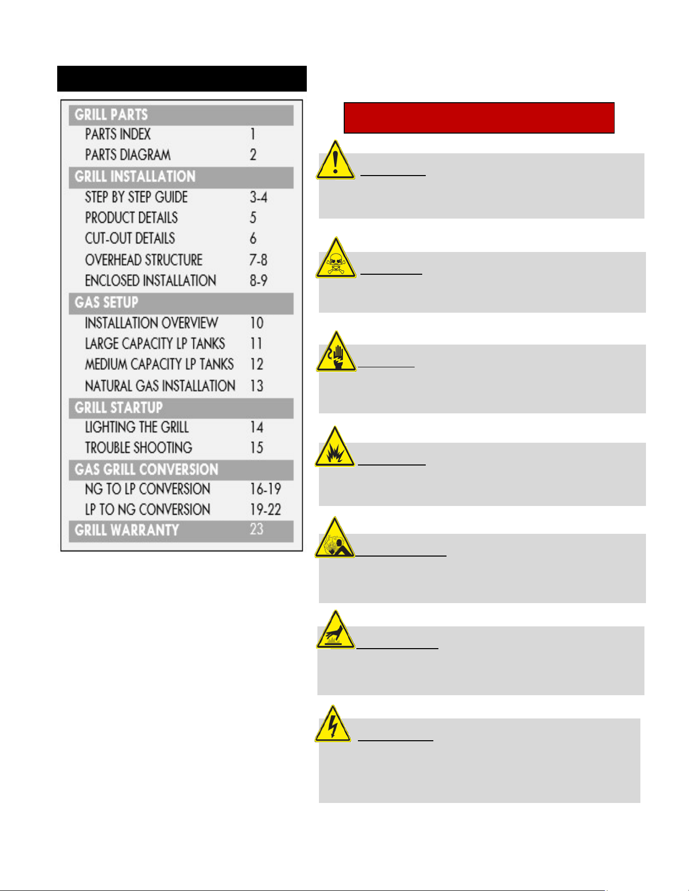
INDEX DIRECTORY
ATTENTION: Indicates a potentially hazardous
situation which, if not avoided, may result in minor or
moderate personal injury, or property damage.
WARNING:
Indicates an imminently hazardous
situation which, if not avoided, will result in death or
serious injury.
VOLTAGE:
Indicates a potentially hazardous
situation which, if not avoided, may result in minor or
moderate electrical shock.
EXPLOSION:
Indicates an imminently hazardous
situation which, if not avoided, will result in possible
explosion and cause death or severe injury.
BODILY INJURY:
Indicates a potentially hazardous
situation which, if not avoided, may result in minor or
moderate personal injury, or property damage.
HOT SURFACE:
Indicates an imminently hazardous
hot surface which, if not avoided, will result in serious
burn or injury.
LIVE CIRCUIT:
Indicates a potentially hazard from
Live electrical current that if extreme caution is not
used, may result in minor or moderate personal injury,
or property damage.
HAZARDS & WARNING SIGNS
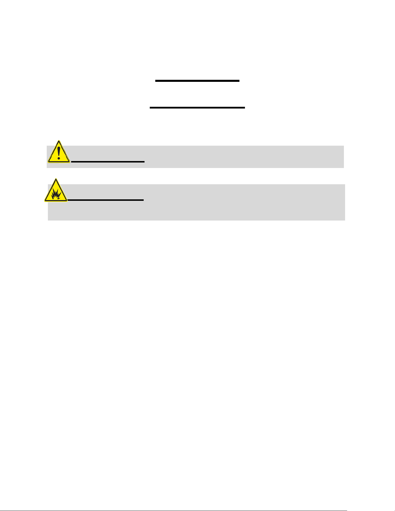
START-UP
CHECKLIST
“FIRST TIME STARTUP CHECKLIST”
Transformer Electrical Plug is properly installed.
Installation of the proper gas type and regulator settings.
The proper Regulator & Gas Connection is complete.
Minimum 24” Inch to Combustible Clearances are maintained.
All packaging has been removed from Interior of Grill
All parts and components are properly installed.
An installer-supplied manual gas shut-off valve is fully accessible.
LP hose is clean and inspected for cuts, wear, abrasion, or leaks.
Replace if necessary, with a suitable UL, ETL or CSA Listed part with
internally threaded connection.
EXPLOSION: When Igniting the Grill – Always keep
the Hood Open.
ATTENTION: Never operate the grill unattended.
NAME
QTY
PART
NUMBER
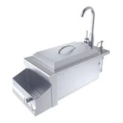
1
COVER
1
SUN13CPRO-CO
2
--
-
3
Cover Classic Handle
1
P-HANDLE
4
Drip Pan Tray
1
SUN13CPRO-PAN
5
Electrical Wire Plug
1
P-ELECT-PLUG
6
Burner Large Knob
2
P-KNOB-L
7
LED Light Button
1
P-LIGHT-BUT
8
LED Light Strip
1
SUN13VDB-LED
9
LED Light Support
1
SUN13CPRO-SUP
10
LED Light Casing
1
SUN13CPRO-CAS
11
LED Clip Bracket
1
SUN13CPRO-BRA
12
Spacing O-Ring + Screw
4
SUN13CPRO-SPACER
13
Control Panel Frame
1
SUN13CPRO-CPANEL
14
Valve Spacer
2
SUN13CPRO-VSPACE
15
Manifold Pipe
1
SUN13CPRO-MANI
16
Piezo Valve – LP/NG
2
SUN13CPRO-VALVE-LP/NG
17
Fire Box
1
SUN13CPRO-FBOX
18
Knob Ring
2
P-KNOB-RING
19
Knob Control Panel
1
SUN13CPRO-KCPANEL
20
Thermo-Coupler
2
SUN13CPRO-THERMO
21
Oil Pan Cover
1
SUN13CPRO-DPANC
22
Flare Adapter –LP/NG
1
SUN13VDB-FLAR-LP/NG
23
Manifold Inner Bracket
1
P-MANI-BRAK-1
24
Manifold Outer Bracket
1
P-MANI-BRAK-2
25
IR Burner Support
1
SUN13CPRO-IRB-SUP
26
Back Vent Panel
1
SUN13CPRO-BVENTP
27
Vent Panel Knob
1
CHDZ42-VENT-KNOB
28
Infra-Red Burners
2
SUN13CPRO-IRBURNER
29
Flavorizer Rack
1
R-FL-3B
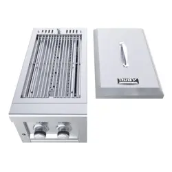
30
Straight 304 SS Grate
1
SUN13CPRO-SGRATE
31
Transformer
1
P-LT
32
LP Regulator
1
LP-REG
33
NG REGULATOR
1
NG-REG
GRILL PARTS– PARTS INDEX
PAGE 1
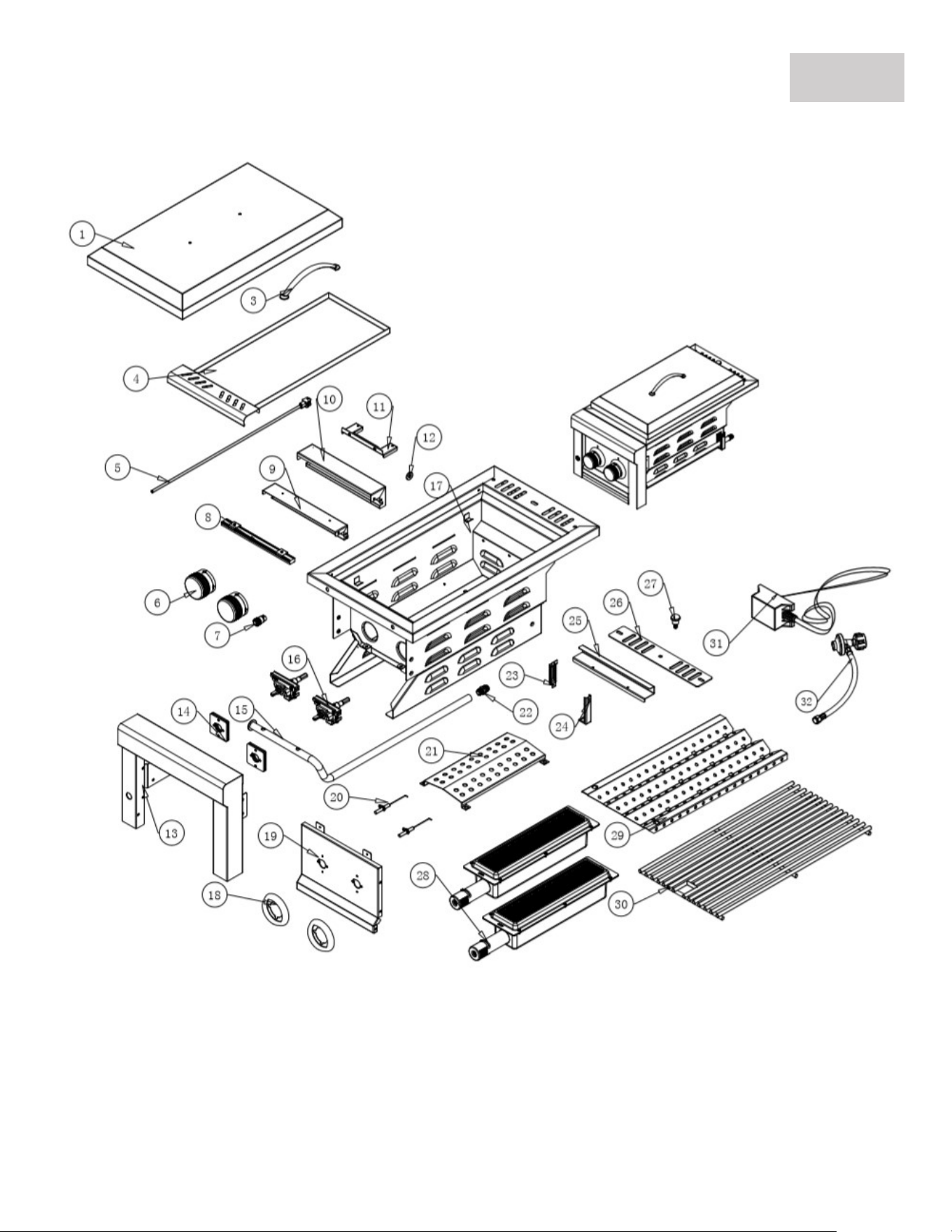
GRILL PARTS – PARTS DIAGRAM
PAGE 2
LIVE CIRCUIT
: Use only with a Ground-Fault Circuit Interrupter - GFCI protected Outlet
with this Grill.
VOLTAGE
: Use only extension cords approved for outdoor use marked with W-A
Certifications and rated for the power of this appliance.
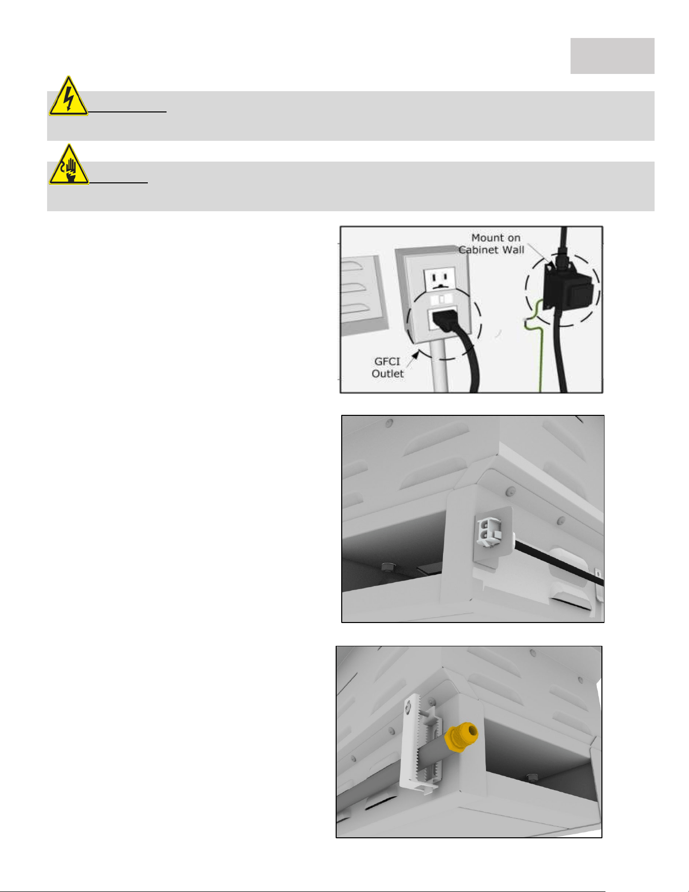
GRILL INSTALLATION – STEP BY STEP GUIDE
1. Mount Transformer
Using metal screws and attach the
transformer to the back inner wall of
your island’s cabinet wall, somewhere
near the already installed GFCI electrical
outlet. When you plug the transformer
in, double check the GFCI breaker
switch, that the outlet has power.
2. Elect. Connection
Locate the Light Button on Left side of
grill control panel. The Transformer's
electrical connection to grill is located
behind control panel, next to light
button. The connection clips together to
form a secure connection. Double check
that all wires are tightly pushed into plug
sockets, so all wires make proper
connections. You can tuck wire into body
of grill or island frame.
PAGE 3
3. Gas Line Connection
See the BACK-RIGHT UNDER-SIDE – This
is where the Gas Line will connect to the
Grill. Grill is shipped as either LP or NG
gas type. Recommendation to have an
18” hose to allow grill to be pulled out if
necessary. For LP & NG Gas Installation,
see pages 11 to 13 for complete
instructions, or call 888-934-9449 for
additional assistance.
5. Silicone Seal
It is recommended to seal all three outer
edges using Clear-Silicone which will
prevent any rain water or insects from
getting down into island enclosure and
or water buildup in the drip pan of grill.
GRILL INSTALLATION – STEP BY STEP GUIDE
PAGE 4
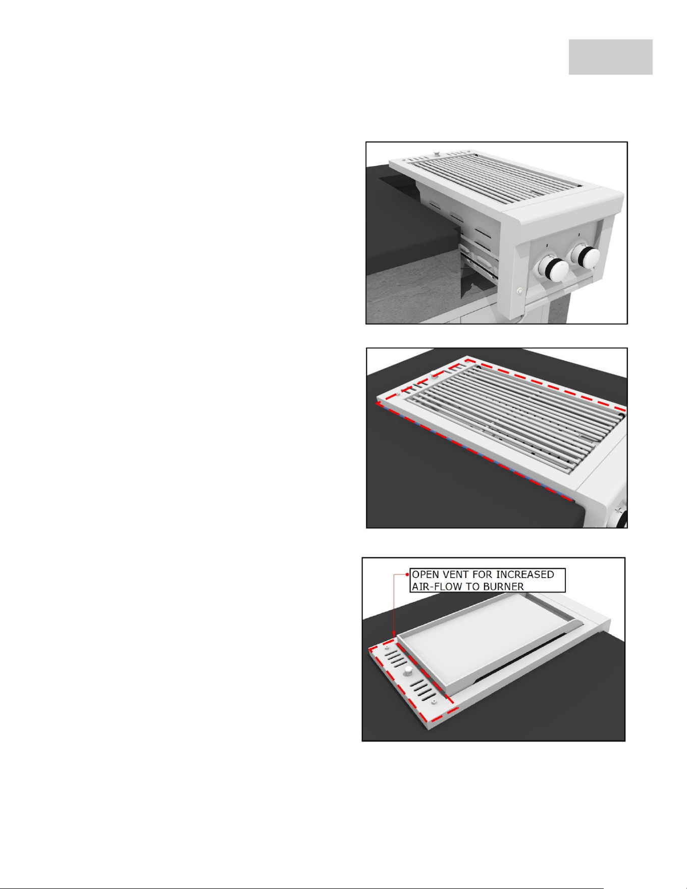
6. Allow for Ventilation
The grill is engineered with special vents
on the back of unit, which allow proper
airflow out of the back of grill. Push grill
all the way into cut-out, there is a
stopper flange just behind the back vent
which will insure the area stays clear for
adequate air flow to the bottom burners.
The Control Panel should be flush
against the front of your island finish
wall, see Cut-Out Details for Notch-Out
Instructions.
4. Slide Grill in Place
The grill is specially designed with an
internal built in hanger lip located at the
Right, Left and Back sides. The grill lip
allows it to hang by the three supported
edges on the right, left and back. The
front control panel requires no
supporting edge, it is designed to hang
down the front of your cut-out.
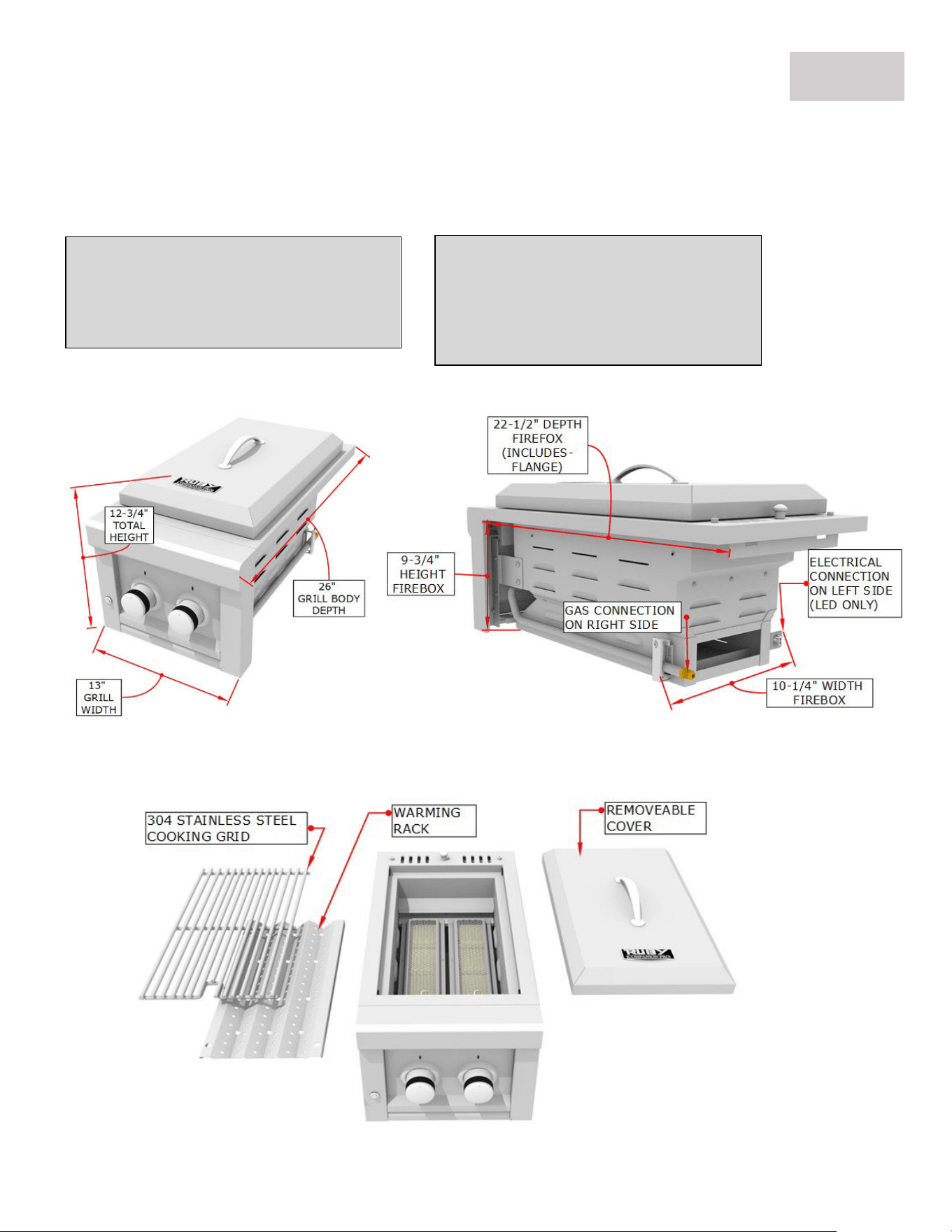
Product Size
Overall Width-------------------- 13"
Overall Height------------------- 12-3/4"
Overall Depth-------------------- 26"
Firebox Size – See next page
Box Width (includes brackets) 10-1/4"
Box Height---------------------- 9-3/4"
Box Depth (includes flange) 22-1/2"
GRILL INSTALLATION – PRODUCT DETAILS
PAGE 5
Technical Measurements
If you are installing grill into cabinet structure you may need to refer to these engineer dimensions
specifically the grill firebox dimensions. (Measurements were obtained from engineer drawing. margin of
error is within 1/8” to actual product)
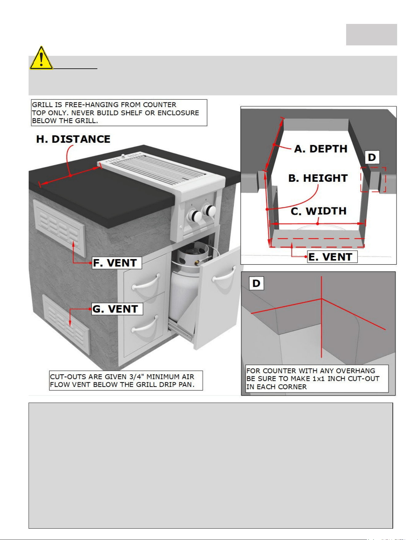
ATTENTION
: Never build an enclosure under the Grill or partition side walls, the Grill
must be Free Hanging supported by the countertop only! Must have clear access to
underside of Grill within reach of at least Two Vents.
PAGE 6
GRILL INSTALLATION – CUT-OUT DETAILS
Countertop Slide-in Installation
(A) Grill Cut-out Depth ------------------------------------------------------------------
22” Depth
(B) Grill Cut-out Height (Allow ¾” Air-Flow Gap Below Drip Pan) ------------
10-1/2” Height
(C) Grill Cut-out Width-------------------------------------------------------------------
11” Width
(D) Notch Out Width should be 13-1/4” to allow grill to slide flush against the island finish wall.
(E) Leave Minimum ¾” Gap below Drip Pan for Air/Gas Ventilation
(F) Must have TWO Vents in HIGH position for Natural Gas
(G) Must have TWO Vents in LOW position for Liquid Propane
(H) MINIMUM 24” DISTANCE TO COMBUSTIBLE MATERIALS
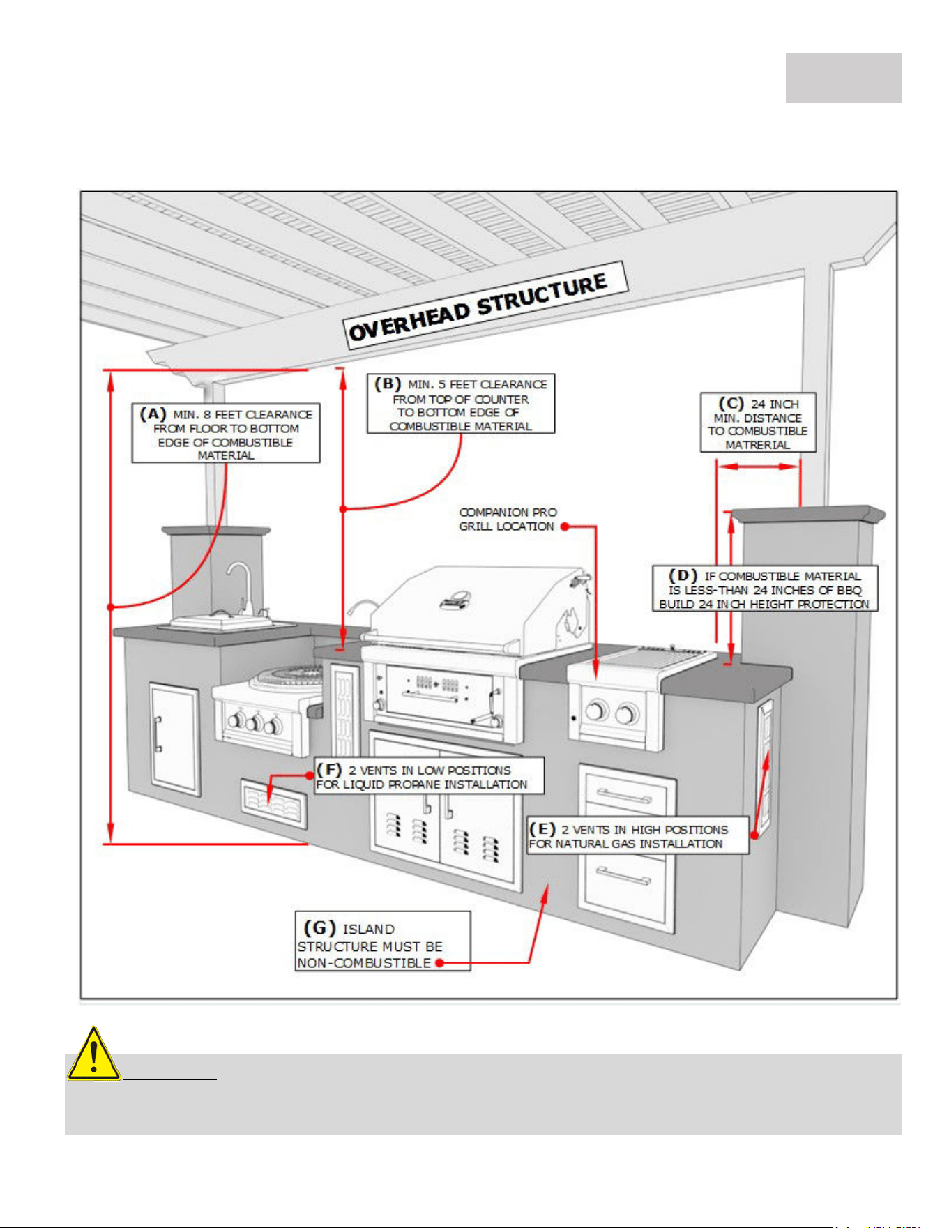
GRILL INSTALLATION – OVERHEAD STRUCTURE
Overhead Structure Definition:
Structure built above Appliance that is sometimes attached to the home’s exterior outside wall or
roof and there is a Minimum of “Two” adjacent sides which are open with outside exposure.
PAGE 7
ATTENTION: All Gas Grill Installations MUST HAVE MINIMUM TWO AIR-FLOW VENTS, either in
ELEVATED POSITION for Natural Gas or LOWERED POSITION for Liquid Propane. Your Warranty may be
VOID if island does not meet basic setup requirements.
Minimum Distances to Combustible Materials or other
Appliance ONLY, Non-Combustible materials do not apply!
(A) Must use vent hood above grill for enclosed structures
(B) Minimum clearance from floor to overhead structure
8’ Min. Clearance
(C) Minimum distance from counter to overhead structure
5’ Min. Clearance
(D) Minimum clearance from all combustible materials
24” Min. Clearance
(E) Must have TWO Vents in HIGH position for Natural Gas
(F) Must have TWO Vents in LOW position for Liquid Propane
(G) Install Non-Combustible Barrier Shielding, Stainless Steel Sheet is recommended.
(H) Island Structure must be Non-Combustible otherwise must use grill jacket or metal cabinet.
BODILY INJURY: Failure to maintain required clearances create a fire hazard that
may result in property damage or serious personal injury.
Clearances to Combustible Construction:
Minimum of 24” from the sides and rear of grill must be maintained to adjacent vertical combustible
construction, above the countertop level. You should take in account that there is a large volume of heat,
and smoke will exhaust from the rear of the grill. This may discolor or damage unprotected areas, do not
install under unprotected combustible construction without using a fire safe ventilation system. A 24”
minimum clearance must be maintained under the countertop to combustible construction. The clearance
can be modified by a use of an insulated jacket.
DEFINITION OF COMBUSTIBLE MATERIAL -
Any
materials of a building structure or decorative structure
made of wood, compressed paper, plant fibers, vinyl/plastic or other materials that are capable of transferring heat
or being ignited and burned. Such material shall be considered combustible even though flame-proofed, fire-
retardant treated or surface-painted, or plastered.
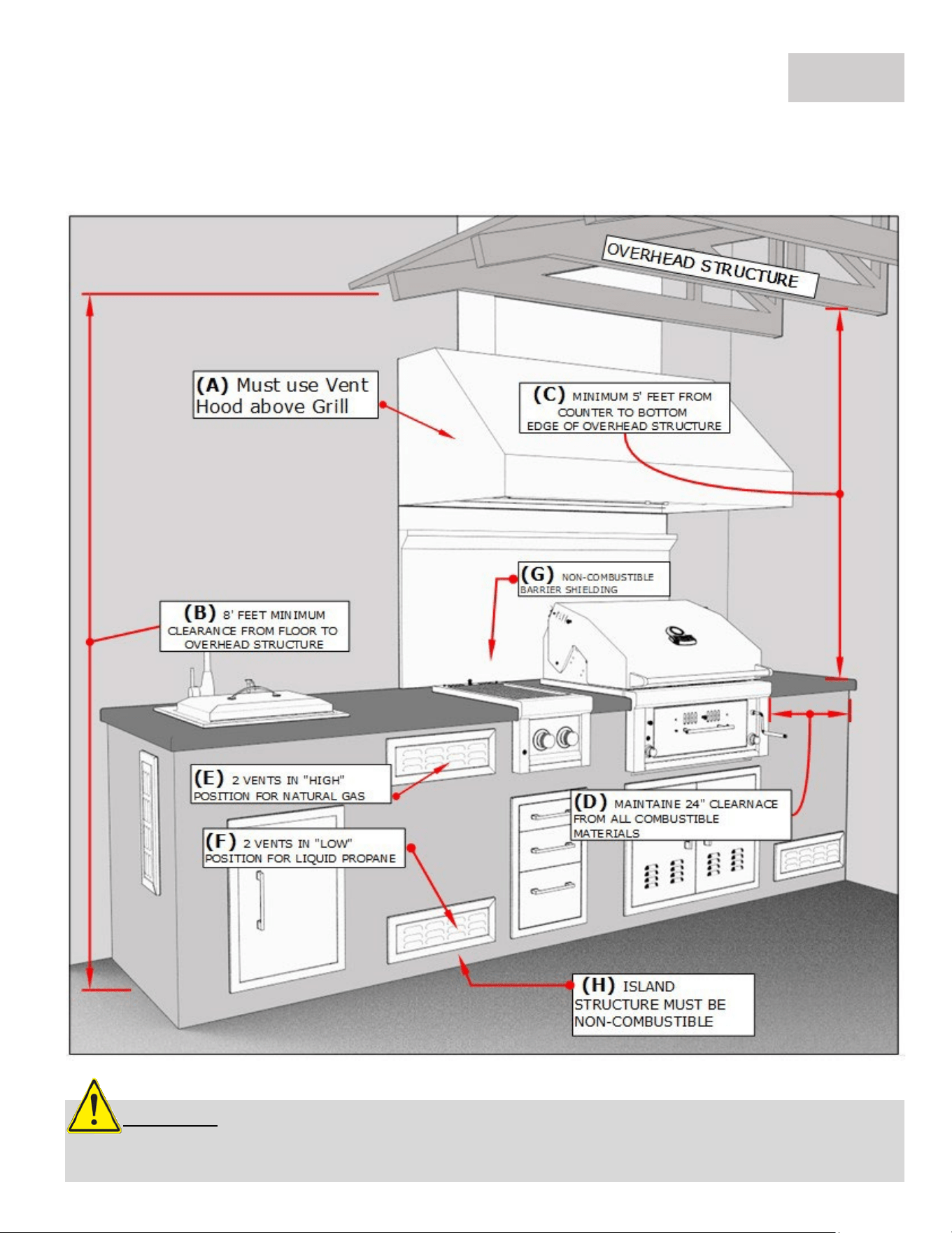
GRILL INSTALLATION – ENCLOSED INSTALLATION
Minimum Distances to Combustible Materials or other
Appliance ONLY, Non-Combustible materials do not apply!
(A) From Floor to Overhead Combustible Structure
8’ Min. Clearance
(B) From Counter to Overhead Combustible Structure
5’ Min. Clearance
(C) From Appliance to Combustible Material
24” Min. Width Clearance
(D) From Counter to Combustible Material if within 24” of Appliance
24" Min. Height Clearance
(E) Must have TWO Vents in HIGH position for Natural Gas
(F) Must have TWO Vents in LOW position for Liquid Propane
PAGE 8
The Table below refers to illustration on page 7
The Table below refers to illustration on page 9
ATTENTION: All Gas Grill Installations MUST HAVE MINIMUM TWO AIR-FLOW VENTS, either in
ELEVATED POSITION for Natural Gas or LOWERED POSITION for Liquid Propane. Your Warranty may be
VOID if island does not meet basic setup requirements.
GRILL INSTALLATION – ENCLOSED INSTALLATION
PAGE 9
Enclosed Installation Definition:
Structure built above Appliance that is attached to the home’s exterior outside wall, roof or is inside a
separate structure like outdoor room and there is a Minimum of “One” Side open with outside exposure.
GAS SETUP – INSTALLATION OVERVIEW
PAGE 10
CAUTION:
Gas conversion kits are available from Customer care by dialing 888-934-9449.
When ordering gas conversion kits, have the model number, and the type of gas (natural or LP) ready.
• Use only the gas pressure regulator supplied with this appliance. This
regulator is set for an outlet pressure of 11 inches water column.
• An installer-supplied gas shut-off valve must be installed in an easily
accessible location.
• All pipe sealants must be an approved type and resistant to the
actions of LP/NG Gas.
• Never use pipe sealant on flare fittings.
• All gas connections should be made by a qualified technician and in
accordance with local codes and ordinances.
• Before connecting grill to gas source, make sure BBQ Grill control
knobs are in “OFF” position.
• Verify the type of gas supply to be used, either Natural Gas or Liquid
Propane, and make sure the marking on the appliance rating label
agrees with that of the supply.
The installation of this appliance must conform with local codes or, in the
absence of local codes, with either National Fuel Gas Code, ANSI Z223.1/ NFPA
54, Natural Gas and Propane Installation Code, CSA B149.1, or Propane Storage
and Handling Code, B149.2, or the Standard for Recreational Vehicles, ANSI A
119.2/ NFPA 1192M, and CSA Z240 RV Series, Recreational Vehicle Code, as
applicable.
ATTENTION: Always take a leak test before lighting the grill to prevent a possible fire or explosion.
Never store a spare propane cylinder in the vicinity of this Grill, or in the vicinity of any other potential heat
source. Never attempt to attach this grill
to the self-contained LP gas system. Do not use grill until leak
testing.
GAS SETUP – LARGE CAPACITY LP TANKS
PAGE 11
ATTENTION:
If you have a Side Yard Propane Tank, you MUST have additional Medium
Pressure Regulator located at the Grill. If you do not serious bodily harm may result or damage to
the grill and island structure from HIGH Heat.
1. For this type of installation, it is most like NG gas installation method, only the
regulator is set for liquid propane. First you will install a gas pipe, coming into island
from outside, be sure the Safety Shut-Off valve is easily accessible.
2. Next, locate the gas manifold on grill, for this type of installation, the LP Regulator
Hose that comes with your LP Burner is not needed. Gas connections are made with
all 3/8" flare Compression Adapters, and UL Gas Hoses.
3. A LP REGULATOR is required for this type of installation, even if the LP Tank is
installed with one already. LP regulator for grill should be set for a minimum of
120,000 BTU's with Medium Pressure. This LP grill does not come with an
independent LP regulator for this type of installation. Contact the company you
purchased from, or your local plumber to locate one, that is made for commercial
style grills.
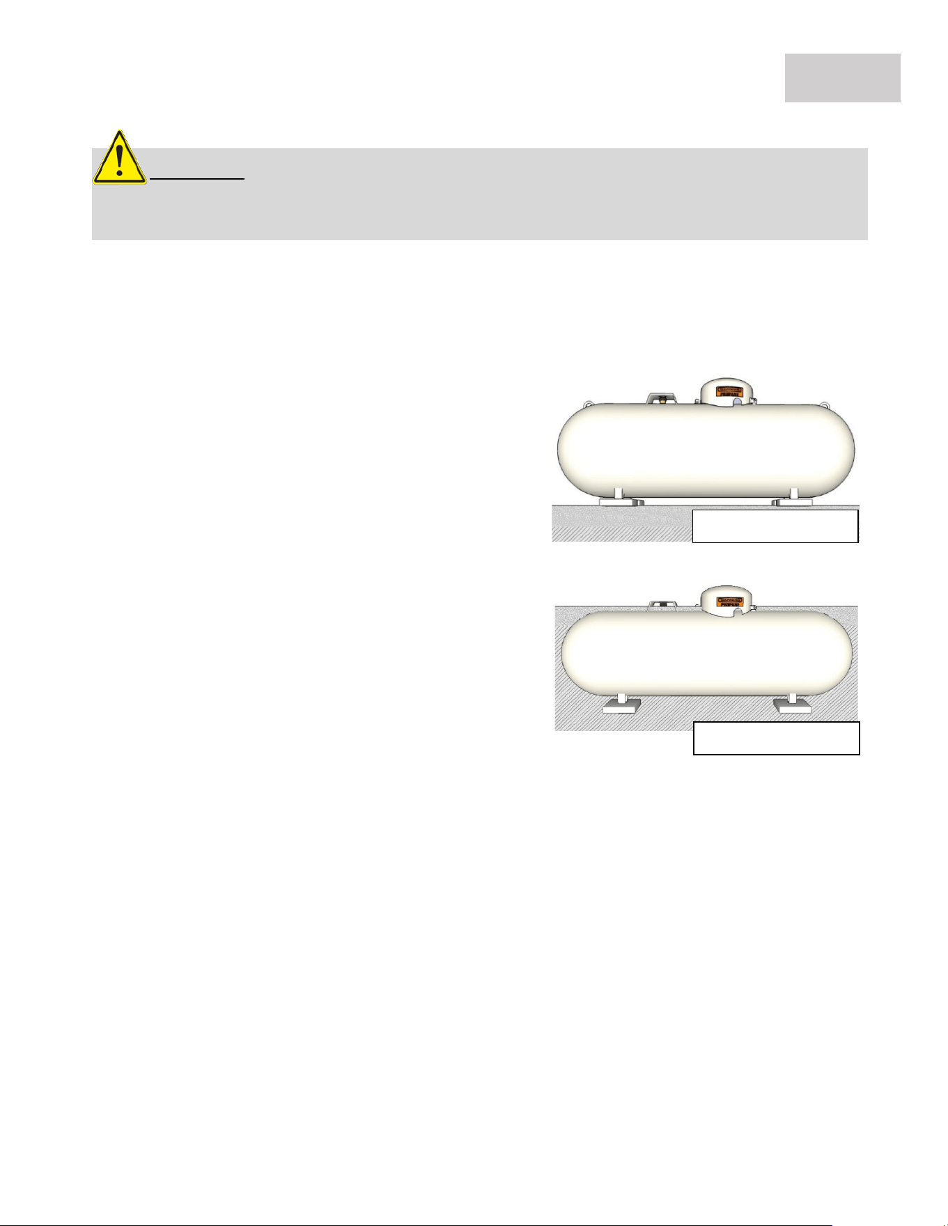
Large Capacity LP Tanks
Propane is delivered to your home as a very cold liquid and is pumped into a specially designed storage
tank which is either Above or Below Ground. The liquid changes to gas before leaving the tank. Propane
tanks are typically painted white or silver to reflect heat and prevent the pressure inside the tank.
If you have a side yard LP tank, it will be either Above or
Below Ground.
• The cover on top of the tank protects several
components from weather and physical damage.
• The tank shut-off valve, which you can close to
stop the flow of propane to your home in case of
a leak or other emergency.
• The regulator, which controls the pressure of the
propane gas coming out of the tank.
• The safety relief valve, which will pop open
automatically if the pressure inside the tank gets
too high. The valve will close again when the
pressure returns to normal.
• The tank gauge, which shows the percentage of
propane in the tank.
Above Ground Tank
Below Ground Tank
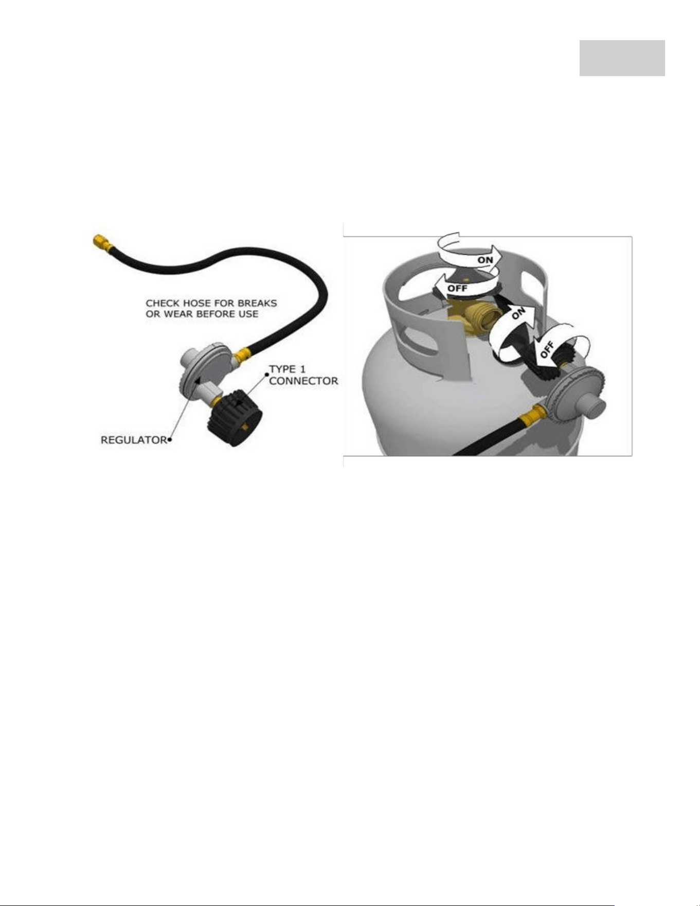
Medium Capacity LP Tank
The Type 1 connection system has the following features:
The system will not allow gas to flow
until a positive connection has been made. NOTE: The cylinder control valve must be turned off
before any connection is made or removed. The system has a thermal element that will shut off
the flow of gas in the event of a fire. The system has a flow limiting device which, when activated,
will limit the flow of gas to 10 cubic feet per hour. NEVER use grill without leak testing.
GAS SETUP – MEDIUM CAPACITY LP TANKS
PAGE 12
Follow Instructions:
1. The tank valve & all Knobs should be in the “OFF” position. If not, turn the knob clockwise until it
stops.
2. Insert the regulator inlet into the tank valve and turn the coupling nut clockwise until the coupler
tightens up (see picture above). Do not overtighten the coupler. Turn the main tank valve on and
turn the burner control valves on the unit to the “HIGH” position for about 20 seconds to allow
the air in the system to purge before attempting to light the burners.
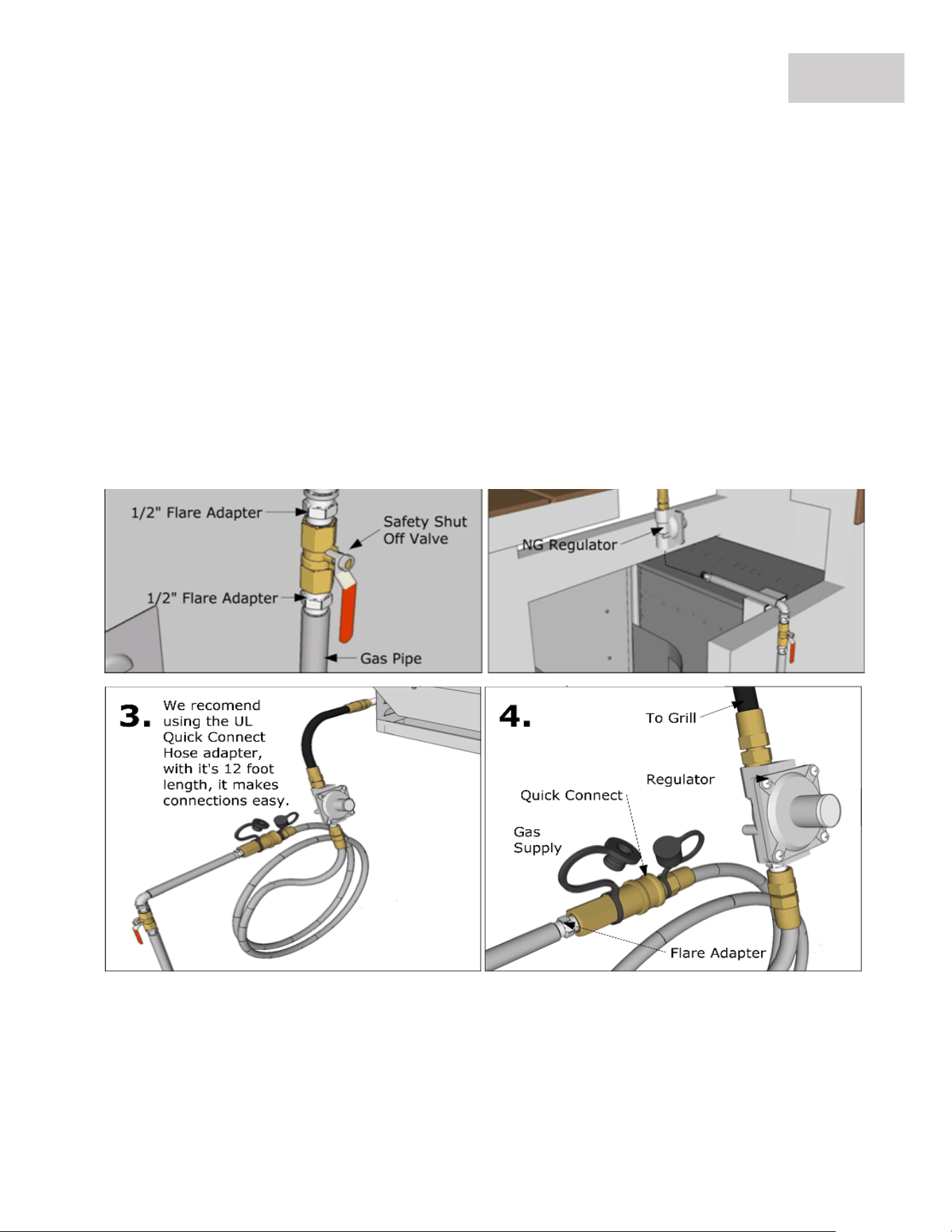
NG Gas Hook-up
The Natural Gas grill is designed to operate on Natural Gas ONLY, at a pressure regulated at 7”water
column (W.C.) equipped with the correct natural gas orifices on the valves and a NG medium
pressure regulator on the supply line located near the grill and regulated at the residential meter.
GAS SETUP – NATURAL GAS INSTALLATION
PAGE 13
Follow Instructions:
1. The tank valve & all Knobs should be in the “OFF” position. If not, turn the knob clockwise until it
stops.
2. Insert the regulator inlet into the tank valve and turn the coupling nut clockwise until the coupler
tightens up (see picture below). Do not overtighten the coupler. Turn the main tank valve on and
turn the burner control valves on the unit to the “HIGH” position for about 20 seconds to allow the
air in the system to purge before attempting to light the burners.
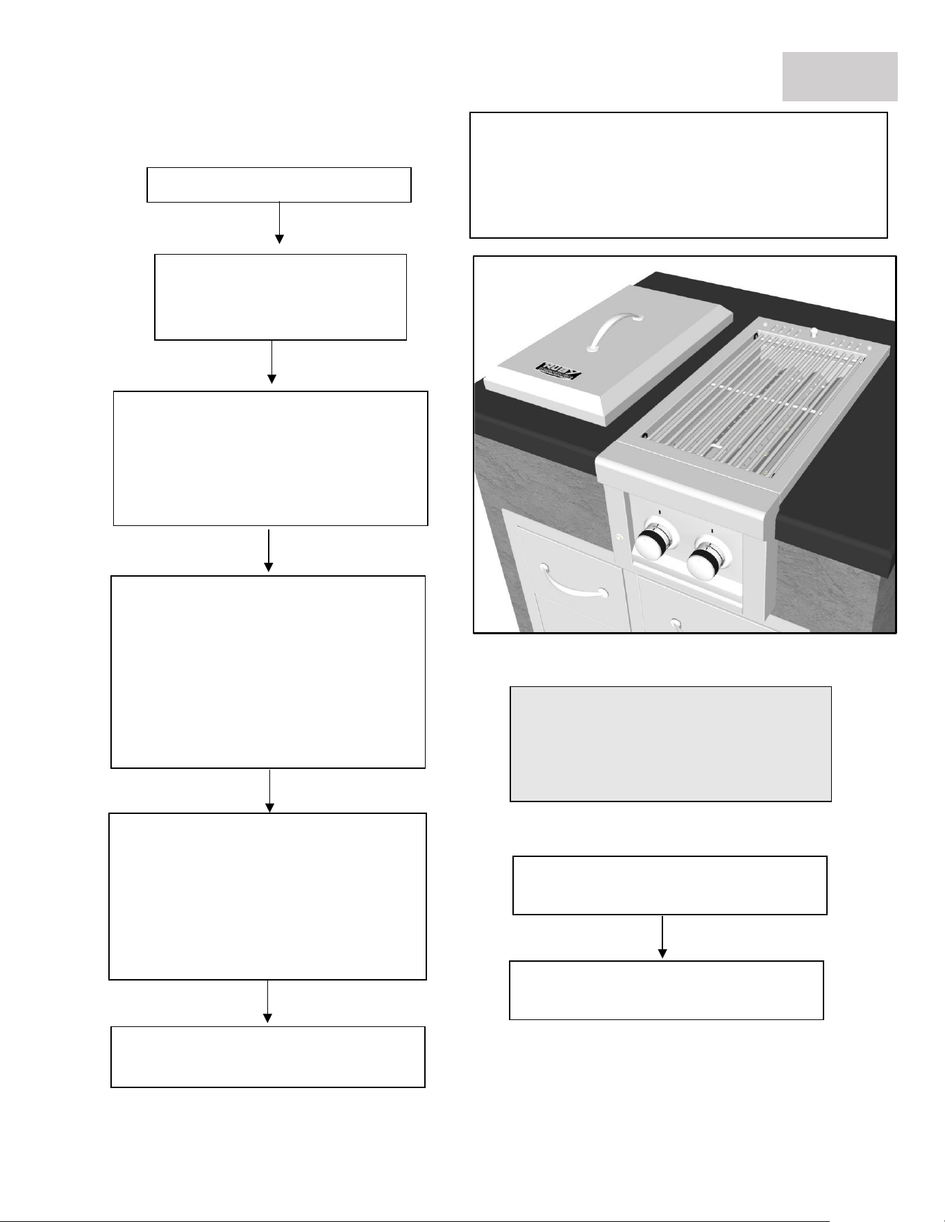
GRILL START-UP – LIGHTING THE GRILL
PAGE 14
REMOVE COVER & OPEN VENT
1. Ensure Grill Control Knobs
are In the OFF position, turn
either KNOB to High Position.
2. Light the Main Burners by turning
either KNOB counter-clockwise
SLOWLY to HIGH Position. Allowing
Gas to Completely Fill the burner
chamber.
3. You will hear a loud click as the
electronic lighter produces a spark.
Listen for the sound of the gas
igniting and look for a glow of Fire
Red through the cooking grids. If the
burner does not light on the first try,
repeat immediately.
4. If the burner does not light in 5
seconds then wait five minutes until
the gas clears before attempting to
light it again. Repeat the procedure or
try manually lighting the burner using
a long neck lighter or spark arrest.
5. Upon successful lighting, repeat
the process on the other burner.
6. To shut off the burners, rotate the
knob and turn to OFF.
7. It is normal to hear a popping
sound when the burners are turned
REMOVE COVER WHEN
LIGHTING THE GRILL & OPEN
BACK VENT PANEL
TIP: The gas must completely fill the
entire burner chamber, so repeat this
procedure until the burner ignites all
the way from front to back.
Q. LED Light is not functioning
A. Likely your LED Light has malfunctioned due to the grill being overheated, or there may be a loose wire on
the internal control circuit board. You can access these components by sliding the grill out from your island
approx. 6 Inches, there are 4 screws on either side holding the front control panel to grill body, and 2 Alan
Wrench Screws on the inside facing towards front panel, you will see 2 Holes. Also unclip the back of grill right
side gas manifold to side of grill. There is an inside box containing the LED light strip you will now have access
to. You can then easily unplug and replace LED light with new one or check for other loose connections.
Q. The Gas Burners flame is very Low
A. If your grill is using a 25 Pound Portable tank and is directly connected to grill with no other appliance, you
may have a Spider Web or other clog in the gas Pipe. If your grill is connected to a Side Yard 500 Gallon Tank,
there may be an issue with the Regulator – either it is a Low-Pressure Regulator being used, or not enough gas
pressure is being allowed to the grill. If you have any T-Connections in gas line going to other outdoor
Appliances like a Fireplace or Side Burner, this can also greatly diminish gas flow.
GRILL START-UP - TROUBLE SHOOTING
PAGE 15
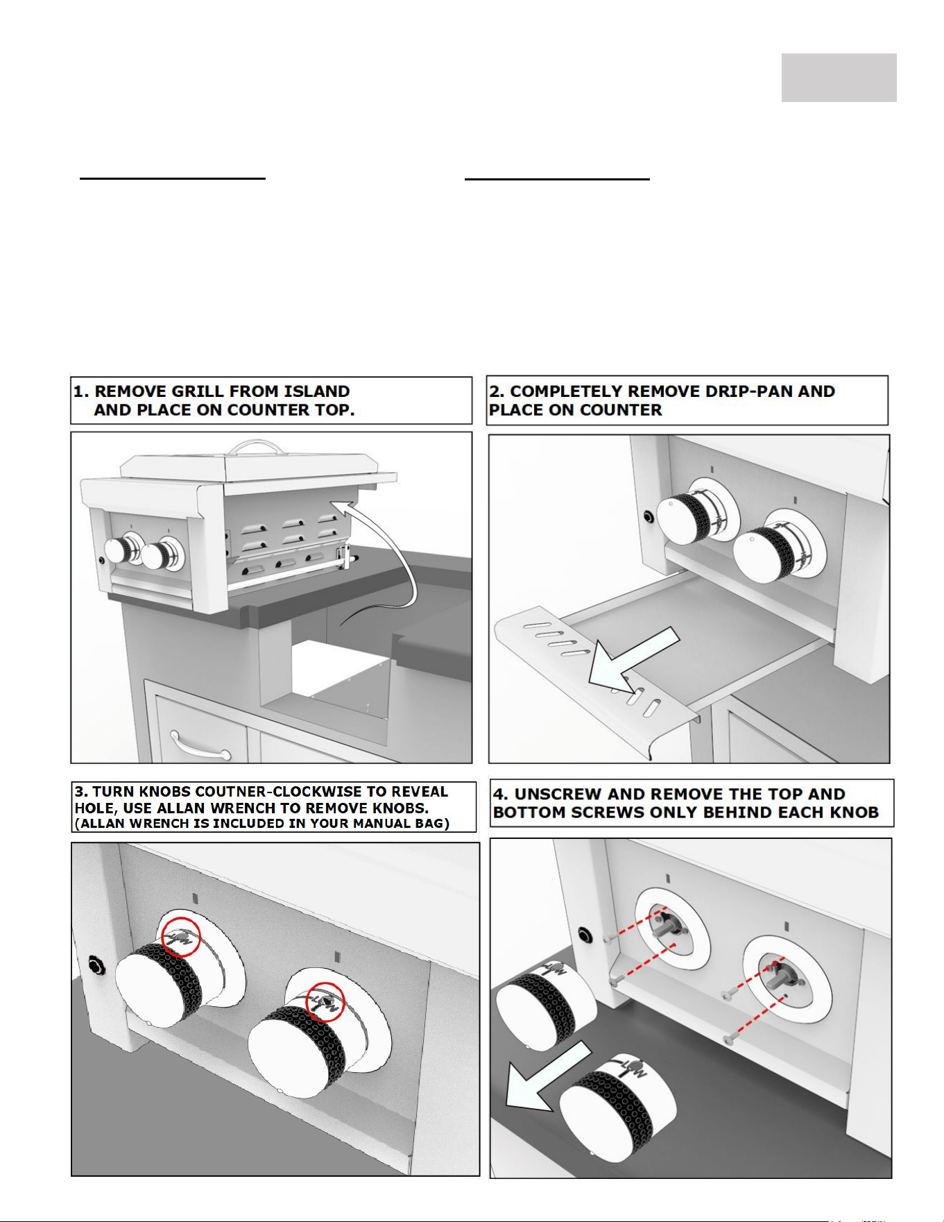
NG TO LP GRILL CONVERSION
PAGE 16
REQUIRED TOOLS
ALLAN WRENCH
(THE ONE INCLUDED IN YOUR
MANUAL)
ADJUSTABLE WRENCH
SCREW DRIVER
(RECOMMEND MAGNETIC ONE)
NEEDLE NOSE PLYIERS
REQUIRED PARTS
(2) LP SUN13CPRO VALVES
LP REGULATOR W/18" HOSE
1/2" TO 3/8" FLARE ADAPTER
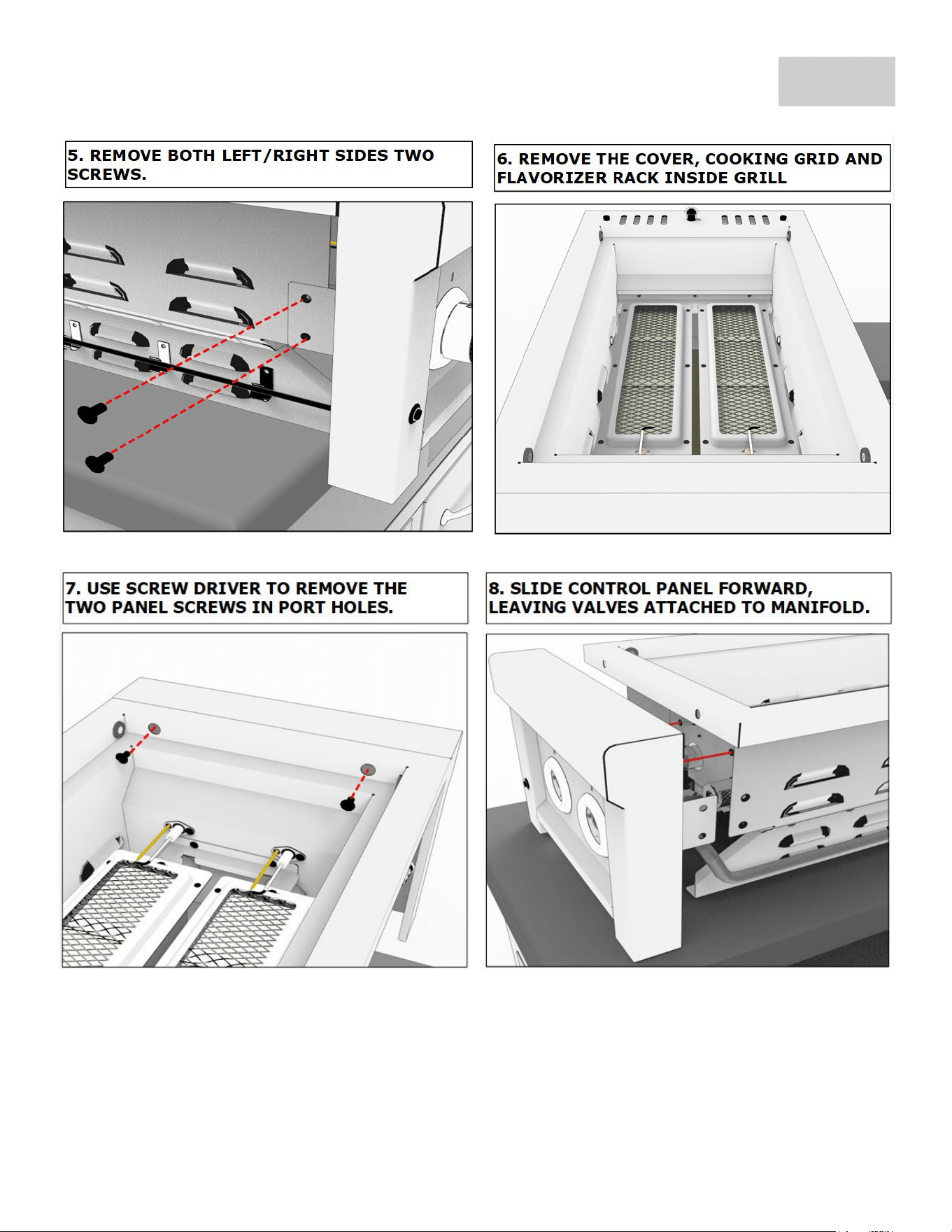
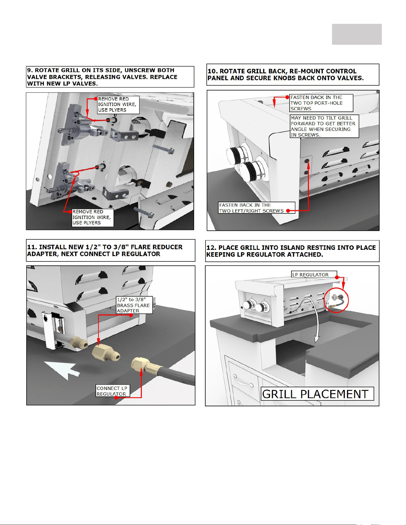
NG TO LP GRILL CONVERSION
PAGE 17
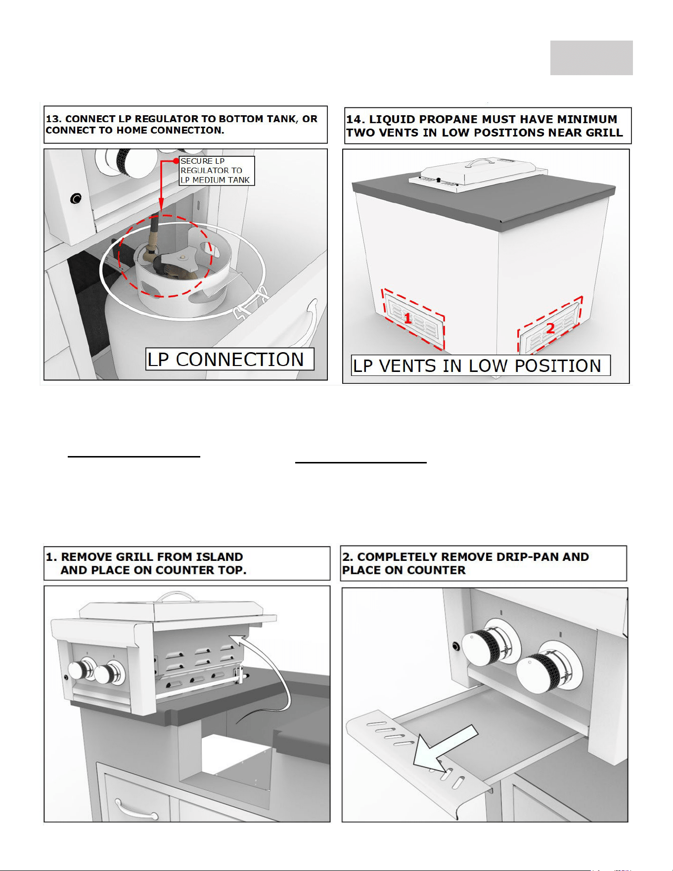
NG TO LP GRILL CONVERSION
PAGE 18
NG TO LP GRILL CONVERSION
PAGE 19
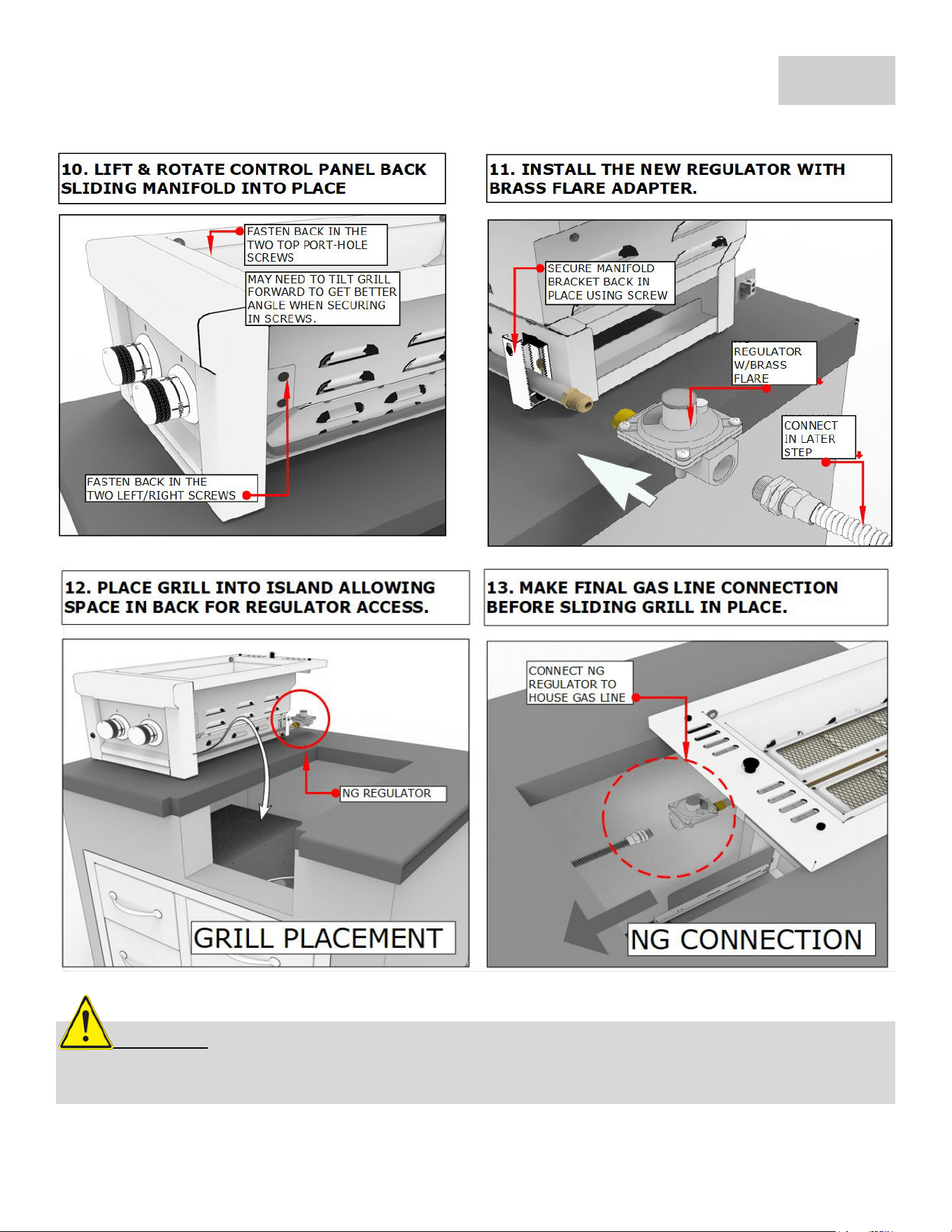
LP TO NG GRILL CONVERSION
REQUIRED TOOLS
SCREW DRIVER
(RECOMMEND MAGNETIC ONE)
ADJUSTABLE WRENCH
POWER DRILL
REQUIRED PARTS
NG REGULATOR WITH 3/8” FLARE ADAPTER
#50 DRILL BIT
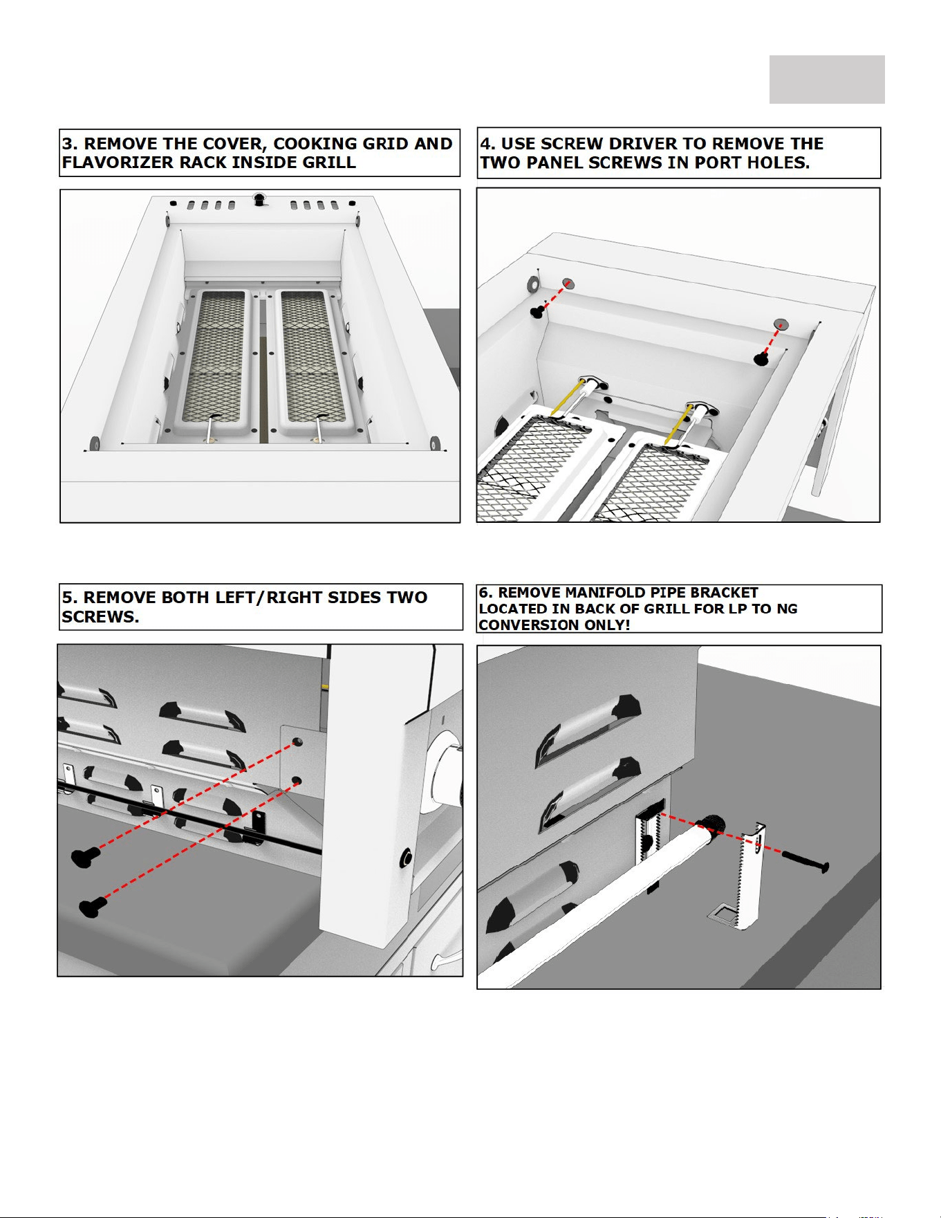
LP TO NG GRILL CONVERSION
PAGE 20
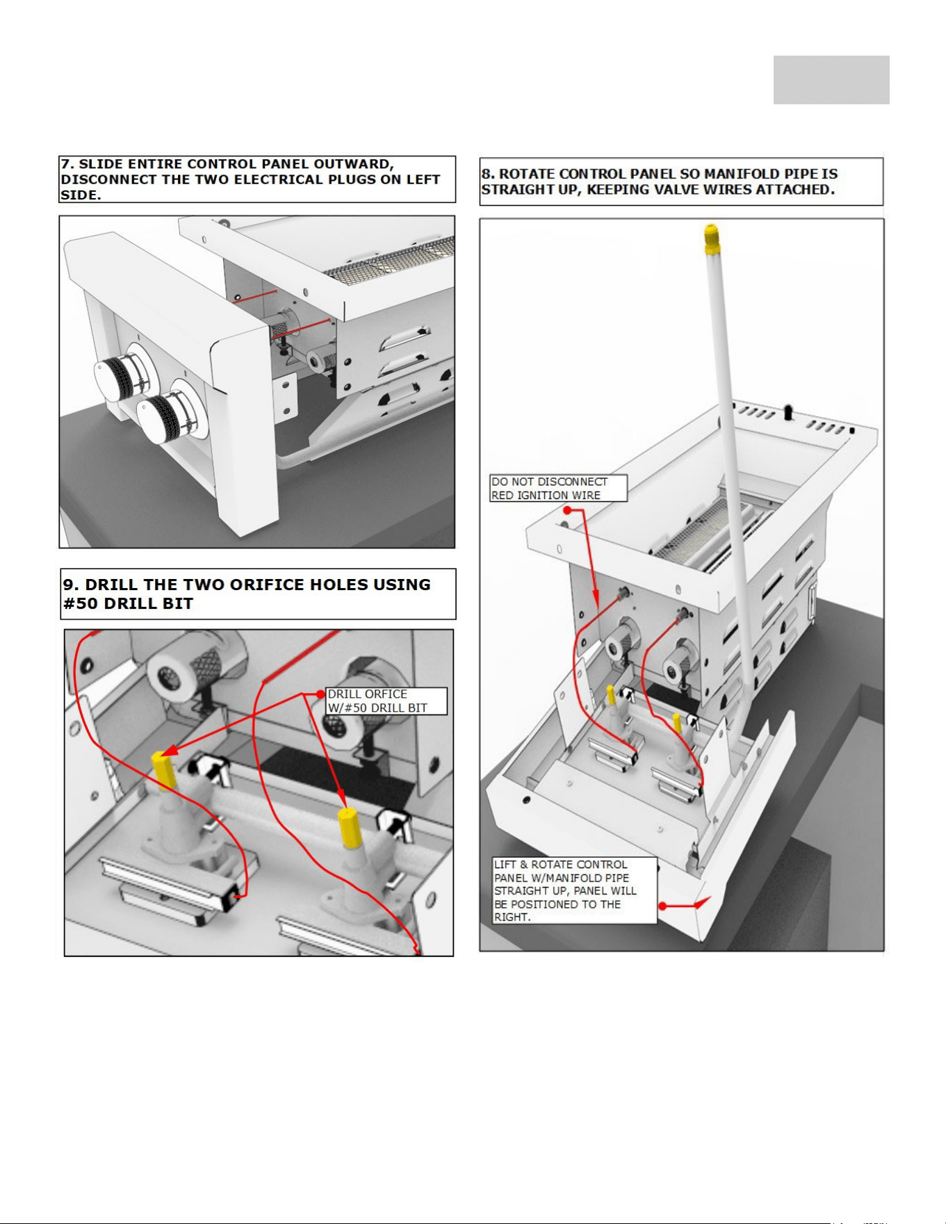
LP TO NG GRILL CONVERSION
PAGE 21
LP TO NG GRILL CONVERSION
PAGE 22
ATTENTION: All Gas Grill Installations MUST HAVE MINIMUM TWO AIR-FLOW VENTS, either in
ELEVATED POSITION for Natural Gas or LOWERED POSITION for Liquid Propane. Your Warranty may be
VOID if island does not meet basic setup requirements.

GRILL WARRANTY
PAGE 23
ATTENTION:
The Grill must be installed according to the product manual. If your grill
installation does not meet the Basic Setup Instructions
ALL WARRANTIES MAY BE VOID
.
SUNSTONE SERIES 13” GAS COMPANION PRO GRILL WARRANTY
***All Warranties Start from the Date of Purchase***
LIMITED LIFETIME WARRANTY
Sunstone Stainless Rod Cooking Grid and Stainless-Steel Housings (including liners, frames, firebox and hood and all exterior
grill faces) are warranted for as long as you own the Sunstone Barbecue Grill against all factory defects. This warranty does
not cover against consumer usage wear and tear from using the grill as all grilling methods will erode the 304 Stainless Steel
Materials.
LIMITED LIFETIME WARRANTY WITH ONE YEAR BURNER REPLACMENT
The Stainless-Steel Gas IR Burner w/Ceramic Plates is warranted for as long as you own the Sunstone Barbecue Grill against
all factory defects. In addition, the Burner is covered for the first full year from date of purchase with FREE replacement
against all wear and tear. This warranty covers the burner only, it does not cover the cost of a service tech to replace the
burner.
LIMITED ONE-YEAR WARRANTY
All other grill components including, thermometer, light assemblies, gas-valves, piezo-igniters, springs, all electrical wire are
warranted to be free from defects in material and workmanship for a period of one year from the original date of purchase.
LIMITATIONS & EXCLUSIONS
1. SUNSTONE warranty applies only to the original purchaser and may not be transferred.
2. SUNSTONE warranty is in lieu of all other warranties expressed or implied and all other obligations or liabilities
related to the sale or use of its grill products.
3. SUNSTONE warranty shall not apply, and SUNSTONE is not responsible for damage resulting from misuse, abuse,
alteration of or tampering with the appliance, accident, hostile environment, flare-up fires, improper installation, or
installation not in accordance with the instructions contained in the User Manual, or the local codes.
4. SUNSTONE is not responsible for warping of component parts due to overheating or using in a way not in line with
the product manual.
5. SUNSTONE shall not be liable for incidental, consequential, special or contingent damages resulting from its breach
of this written warranty or any implied warranty.
6. Some states do not allow limitations on how long an implied warranty lasts, or the exclusions of or limitations on
Consequential damages. This warranty gives you specific legal rights and you may have other rights, which vary
from state to state.
7. No one has the authority to add to or vary SUNSTONE warranty, or to create for SUNSTONE any other obligation or
liability in connection with the sale or use of its products.
8. SUNSTONE DOES NOT COVER FOR WARPING OF STEEL DRAWER, GRATES, OR ANY OTHER COMPONENT FROM THE
RESULT OF MISUSE OR OVERHEATING OF COMPONETS.
WHAT IS NOT COVERED. & INTERNET PURCHASE DISCLAIMER
SUNSTONE shall not be responsible for and shall not pay for the following Installation or start-up.
1. Service by an unauthorized service provider and the cost of a service tech of any warrantied parts.
2. Damage or repair due to service by an unauthorized service provider or use of unauthorized parts.
3. Damage caused by accidents, abuse, alteration, misuse, installation that is not in accordance with the instructions
contained in the User Manual, or local codes.
4. To correct normal adjustments or settings, due to improper installation, commissioning or local gas supply
properties.
5. Shipping and handling costs, export duties, or installation cost.
6. The cost of service calls to diagnose trouble; or Removal or re-installation cost.
This warranty applies to the original purchaser with invoice or proof of purchase and covers Sunstone products intended for personal, family or household
usage only. It does not apply to surface rust, corrosion, oxidation or discoloration, which may occur due to moisture or overheating, unless the affected
component becomes inoperable. This warranty does not cover parts becoming defective by misuse, accidental damage, improper handling and/or
installation. It does not cover labor or labor related charges. It specifically excludes liability for indirect, incidental or consequential damages. Some states
do not allow the exclusion or limitation of incidental or consequential damages, so the above exclusion or limitation may not apply to you. This warranty
gives you specified legal rights and you may have other rights which may vary from state to state.