Loading ...
Loading ...
Loading ...
[] A main vent can be used for venting a group of dryers. The
main vent should be sized to remove 200 CFM of air per
dryer. Large-capacity lint screens of proper design may be
used in the main vent if checked and cleaned frequently. The
room where the dryers are located should have make-up air
equal to or greater than the CFM of all the dryers in the room.
[] Back-draft Damper Kit, Part No. 3391910, is available from
your dealer and should be installed in the vent of each dryer
to prevent exhausted air from returning into the dryers and
to keep the exhaust in balance within the main vent.
Unobstructed air openings are required.
Each vent should enter the main vent at an angle pointing in the
direction of the airflow. Vents entering from the opposite side
should be staggered to reduce the exhausted air from interfering
with the other vents.
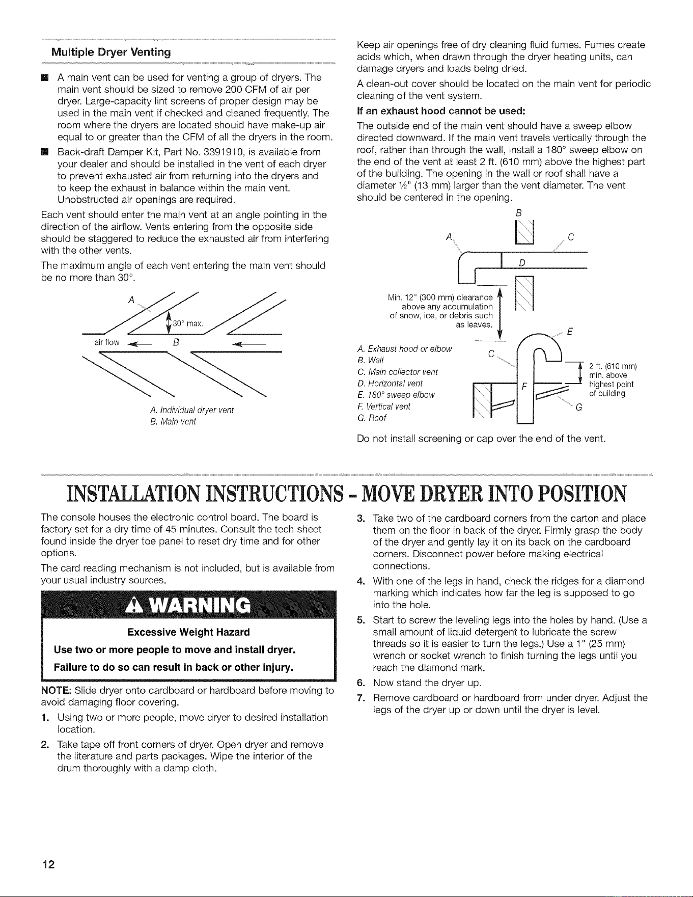
The maximum angle of each vent entering the main vent should
be no more than 30°.
air flow _ B -_---
A. Individualdryervent
B. Mainvent
Keep air openings free of dry cleaning fluid fumes. Fumes create
acids which, when drawn through the dryer heating units, can
damage dryers and loads being dried.
A clean-out cover should be located on the main vent for periodic
cleaning of the vent system.
If an exhaust hood cannot be used:
The outside end of the main vent should have a sweep elbow
directed downward. If the main vent travels vertically through the
roof, rather than through the walt, install a 180° sweep elbow on
the end of the vent at least 2 ft. (610 mm) above the highest part
of the building. The opening in the walt or roof shall have a
diameter 1Z2"(13 mm) larger than the vent diameter. The vent
should be centered in the opening.
B
A .... U .....C
A. Exhausthoodorelbow
B. Wall 2 ft. (610 mm)
C.Maincollectorvent min.above
D.Horizontalvent highestpoint
E. 180° sweepelbow of building
F.Verticalvent
G.Roof
Do not install screening or cap over the end of the vent.
INSTALLATIONINSTRUCTIONS- MOVEDRYERINTOPOSITION
The console houses the electronic control board. The board is
factory set for a dry time of 45 minutes. Consult the tech sheet
found inside the dryer toe panel to reset dry time and for other
options.
The card reading mechanism is not included, but is available from
/our usual industry sources.
Excessive Weight Hazard
Use two or more people to move and install dryer.
Failure to do so can result in back or other injury.
NOTE: Slide dryer onto cardboard or hardboard before moving to
avoid damaging floor covering.
1. Using two or more people, move dryer to desired installation
location.
2. Take tape off front corners of dryer. Open dryer and remove
the literature and parts packages. Wipe the interior of the
drum thoroughly with a damp cloth.
3. Take two of the cardboard corners from the carton and place
them on the floor in back of the dryer. Firmly grasp the body
of the dryer and gently lay it on its back on the cardboard
corners. Disconnect power before making electrical
connections.
4. With one of the legs in hand, check the ridges for a diamond
marking which indicates how far the leg is supposed to go
into the hole.
5. Start to screw the leveling legs into the holes by hand. (Use a
small amount of liquid detergent to lubricate the screw
threads so it is easier to turn the legs.) Use a 1" (25 mm)
wrench or socket wrench to finish turning the legs until you
reach the diamond mark.
6. Now stand the dryer up.
7. Remove cardboard or hardboard from under dryer. Adjust the
legs of the dryer up or down until the dryer is level.
12
Loading ...
Loading ...
Loading ...