
Loading ...
Loading ...
Loading ...
7
English
Fig.C
1415
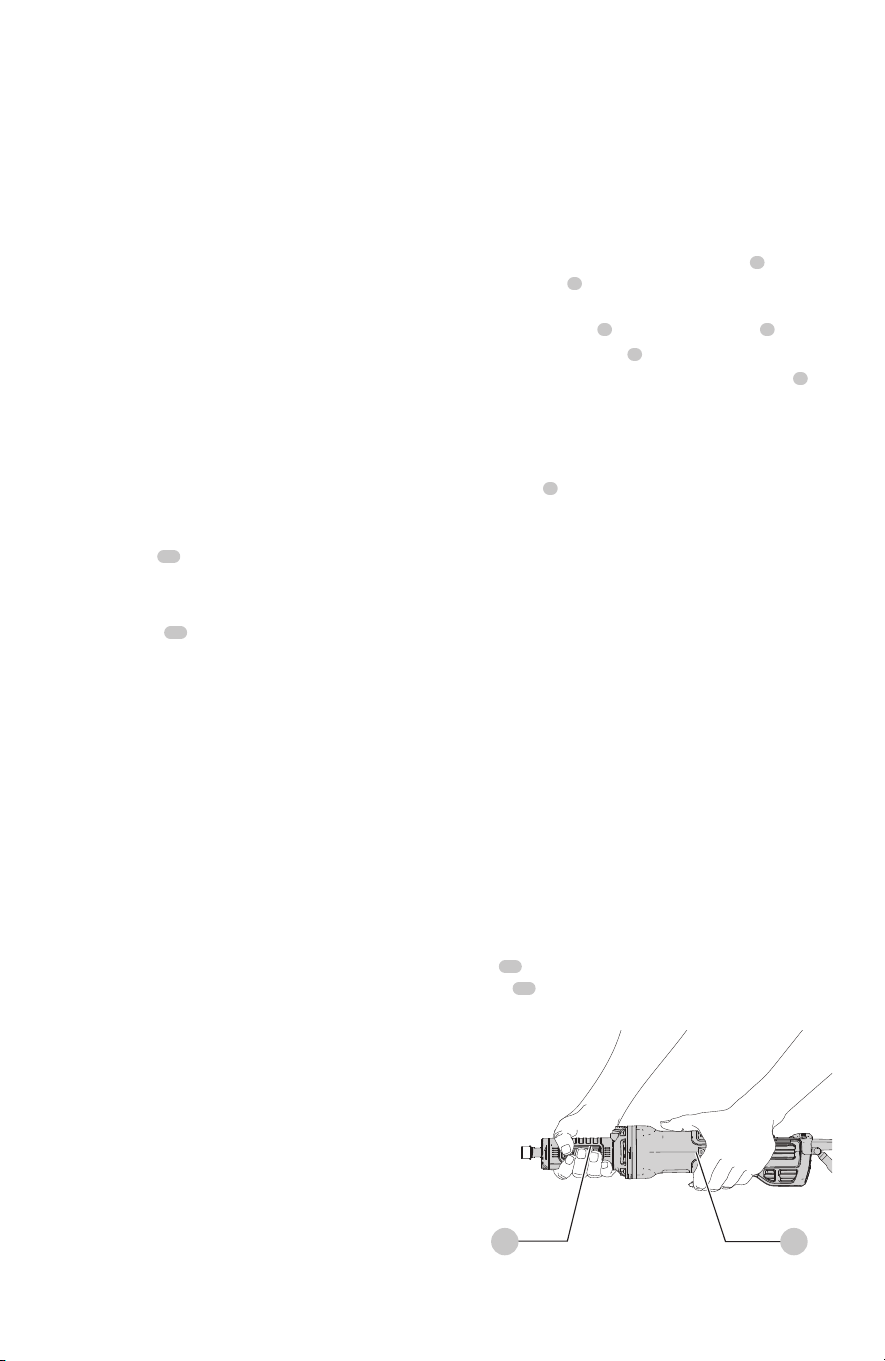
Proper Hand Position (Fig. C)
WARNING: To reduce the risk of serious personal
injury, ALWAYS use proper hand position as shown.
WARNING: To reduce the risk of serious personal
injury, ALWAYS hold securely in anticipation of a
suddenreaction.
Proper hand position requires one hand on the tool
body
14
, with the other hand on the neck of the die
grinder
15
.
OPERATION
WARNING: To reduce the risk of serious personal
injury, turn unit off and disconnect it from
power source before making any adjustments or
removing/installing attachments or accessories.
An accidental start-up can causeinjury.
Mounting an Accessory (Fig. A)
WARNING: Accessories must be rated at least
equal to the maximum speed marked on the tool.
Accessories running faster than their rated speed can
break and flyapart.
WARNING: Accessories must be within the capacity
rating marked on the tool. Incorrectly sized accessories
cannot be adequatelycontrolled.
WARNING: Do not use accessories with a mandrel
length exceeding 2.0" (50mm). Ensure that the
Accessories (Fig. A)
The capacity of the DWE4997NVS, DWE4997VS is 2"
(50mm)diameter.
WARNING: Handle and store all abrasive wheels
carefully to prevent damage from thermal shock, heat,
mechanical damage, etc. Store in a dry protected area
free from high humidity, freezing temperatures or
extreme temperaturechanges.
ASSEMBLY AND ADJUSTMENTS
WARNING: To reduce the risk of serious personal
injury, turn unit off and disconnect it from
power source before making any adjustments or
removing/installing attachments or accessories.
An accidental start-up can causeinjury.
exposed mandrel length is no more than 1.0" (25mm)
after inserting accessory intocollet.
WARNING: Projectile hazard. Only use bits with
shanks that match the installed collet. Smaller
shank bits will not be secure and could become loose
duringoperation.
CAUTION: Never tighten the collet without first
installing an accessory in it. Tightening an empty
collet, even by hand, can damage thecollet.
This tool comes with a 1/4" (6.35 mm) collet
5
. A 1/8"
reducing sleeve
6
is also available for use with 1/8"
shaftaccessories.
1. Hold the spindle
1
using the spindle lock
2
.
2. Loosen the collet nut
3
by turning itcounterclockwise.
3. Insert the shank of the accessory into the collet
5
for
accessories with 1/4"shaft.
nOTE: Insert the reducing sleeve into the collet before
the accessory shaft for use with 1/8" shaftaccessories.
4. Securely tighten the collet using the larger
spanner
4
provided.
To remove the accessory, proceed in reverseorder.
When starting the tool (with a new or replacement wheel
installed) hold the tool in a well protected area. If the wheel
has an undetected crack or flaw, it should burst in less than
one minute. Never start tool with a person in line with the
wheel. This includes theoperator.
Brake
When the paddle switch is released the motor immediately
turns off and electronically brakes stopping the
accessoryquickly.
Kickback Brake™
When a severe pinch, stall, or bind-up event is sensed the
electronic brake engages with maximum force to quickly
stop the wheel, reduce the movement of the grinder, and
shut the grinder off. Turn the unit on to restarttool.
Constant Clutch™
When overloaded or stalled the motor torque is reduced. If
load is reduced the torque and RPM will increase. If the tool
is stalled for an extended amount of time it will shut-off and
require the switch to cycle torestart.
Variable Speed Dial (Fig. A)
WARNING: Regardless of the speed setting, the rated
speed of the accessory must be at least equal to the
maximum speed marked on the powertool.
The variable speed dial offers added tool control and
enables the tool to be used at optimum conditions to suit
the accessory andmaterial.
• Turn the dial
11
to the desired level. Turn the dial to the
right for higher speed and to the left for lowerspeed.
LED Indicator (Fig. A)
The LED indicator
12
will remain lit green during normal
activity, or blink in a pattern of red light to alert you a
tool protection feature has been activated. Refer to the
LED Guide at the back of this manual for explanations of
blinkpatterns.
Loading ...
Loading ...
Loading ...